JP2017523332A - Toilet equipment - Google Patents
Toilet equipment Download PDFInfo
- Publication number
- JP2017523332A JP2017523332A JP2017526019A JP2017526019A JP2017523332A JP 2017523332 A JP2017523332 A JP 2017523332A JP 2017526019 A JP2017526019 A JP 2017526019A JP 2017526019 A JP2017526019 A JP 2017526019A JP 2017523332 A JP2017523332 A JP 2017523332A
- Authority
- JP
- Japan
- Prior art keywords
- toilet device
- bowl
- pressurized water
- tank
- cleaning liquid
- Prior art date
- Legal status (The legal status is an assumption and is not a legal conclusion. Google has not performed a legal analysis and makes no representation as to the accuracy of the status listed.)
- Pending
Links
Images


Classifications
-
- E—FIXED CONSTRUCTIONS
- E03—WATER SUPPLY; SEWERAGE
- E03D—WATER-CLOSETS OR URINALS WITH FLUSHING DEVICES; FLUSHING VALVES THEREFOR
- E03D1/00—Water flushing devices with cisterns ; Setting up a range of flushing devices or water-closets; Combinations of several flushing devices
- E03D1/24—Low-level flushing systems
- E03D1/28—Bowl integral with the flushing cistern
- E03D1/283—Bowl integral with the flushing cistern provided with a bell or tube siphon
-
- E—FIXED CONSTRUCTIONS
- E03—WATER SUPPLY; SEWERAGE
- E03D—WATER-CLOSETS OR URINALS WITH FLUSHING DEVICES; FLUSHING VALVES THEREFOR
- E03D1/00—Water flushing devices with cisterns ; Setting up a range of flushing devices or water-closets; Combinations of several flushing devices
- E03D1/02—High-level flushing systems
- E03D1/06—Cisterns with tube siphons
- E03D1/08—Siphon action initiated by air or water pressure
- E03D1/082—Siphon action initiated by air or water pressure in tube siphons
- E03D1/085—Siphon action initiated by air or water pressure in tube siphons by injection of air or water in the short leg of the siphon
-
- E—FIXED CONSTRUCTIONS
- E03—WATER SUPPLY; SEWERAGE
- E03D—WATER-CLOSETS OR URINALS WITH FLUSHING DEVICES; FLUSHING VALVES THEREFOR
- E03D1/00—Water flushing devices with cisterns ; Setting up a range of flushing devices or water-closets; Combinations of several flushing devices
- E03D1/02—High-level flushing systems
- E03D1/14—Cisterns discharging variable quantities of water also cisterns with bell siphons in combination with flushing valves
- E03D1/141—Cisterns discharging variable quantities of water also cisterns with bell siphons in combination with flushing valves in cisterns with tube siphons and with tube siphons in combination with flushing valves
-
- E—FIXED CONSTRUCTIONS
- E03—WATER SUPPLY; SEWERAGE
- E03D—WATER-CLOSETS OR URINALS WITH FLUSHING DEVICES; FLUSHING VALVES THEREFOR
- E03D5/00—Special constructions of flushing devices, e.g. closed flushing system
- E03D5/02—Special constructions of flushing devices, e.g. closed flushing system operated mechanically or hydraulically (or pneumatically) also details such as push buttons, levers and pull-card therefor
- E03D5/09—Special constructions of flushing devices, e.g. closed flushing system operated mechanically or hydraulically (or pneumatically) also details such as push buttons, levers and pull-card therefor directly by the hand
- E03D5/092—Special constructions of flushing devices, e.g. closed flushing system operated mechanically or hydraulically (or pneumatically) also details such as push buttons, levers and pull-card therefor directly by the hand the flushing element, e.g. siphon bell, being actuated through a lever
Abstract
本発明は、ボウル(10)と、洗浄液を貯溜可能でかつ該洗浄液を排出するための排出手段が配設されたタンク(101)を有しかつ前記ボウル(10)と並設された洗浄装置(100)と、を備えたトイレ装置(1)に係るものであって、該トイレ装置(1)は、加圧水を供給する給水ネットワークに接続され、ボウル(10)に開口する柱状管(114)と、前記給水ネットワークと柱状管(114)との間に介在されたベンチュリ管であって、タンク(101)内の洗浄液をボウル(10)内に排出させるために、前記加圧水の圧力を減少させて該洗浄液を吸引するように、タンク(101)内の略底部に配置されたベンチュリ管(130)と、前記加圧水の前記排出手段への流入を制御する手動トリガーアクチュエータ及びロッド(126)に接続された、多量洗浄フロート(127)又は少量洗浄フロート(128)と、を備える。The present invention has a bowl (10) and a washing apparatus having a tank (101) in which a washing liquid can be stored and a discharge means for discharging the washing liquid is disposed, and arranged in parallel with the bowl (10). (100), and the toilet device (1) is connected to a water supply network that supplies pressurized water and opens to a bowl (10). And a venturi pipe interposed between the water supply network and the columnar pipe (114) to reduce the pressure of the pressurized water in order to discharge the cleaning liquid in the tank (101) into the bowl (10). A venturi pipe (130) disposed substantially at the bottom of the tank (101) so as to suck the cleaning liquid, and a manual trigger actuator and a rod for controlling the flow of the pressurized water into the discharge means ( Provided connected to 26), a large amount cleaning float (127) or a small amount cleaning float (128), the.
Description
本発明は、トイレ装置、特に洗浄液タンクから洗浄液を排出するための装置に関する技術分野に属する。 The present invention belongs to a technical field related to a toilet device, particularly a device for discharging cleaning liquid from a cleaning liquid tank.
広く使用されているトイレ装置の殆どは、洗浄液タンクを空にするために重力を利用している。従来使用されている機構は、高所に設けられかつボウルに接続された洗浄液タンクを備えている。このタンクは、その下部に設けられた可動閉鎖器により閉鎖される。使用者が洗浄機構を作動させると、閉鎖器が開放されて洗浄液がボウルへと流下する。そしてタンクが空になりかけたときに、洗浄液の流れを止めるために、閉鎖器がタンクの開口を閉鎖する。 Most widely used toilet equipment uses gravity to empty the cleaning liquid tank. A conventionally used mechanism includes a cleaning liquid tank provided at a high place and connected to a bowl. This tank is closed by a movable closure provided in the lower part thereof. When the user activates the cleaning mechanism, the occluder is opened and the cleaning liquid flows down to the bowl. When the tank is about to empty, the closure closes the tank opening to stop the flow of cleaning liquid.
前記のシステムでは、洗浄液タンクを高所に設けなければならないので、製造業者はシステムをコンパクト化することができない。 In the above system, since the cleaning liquid tank must be provided at a high place, the manufacturer cannot make the system compact.
また、栓を移動させる機構の摩耗や栓自体の摩耗が、ボウルへの液漏れの原因となり得る。 Also, wear of the mechanism for moving the stopper and wear of the stopper itself can cause liquid leakage to the bowl.
以上の技術的背景において、本発明は、従来の機構で生じる液漏れの問題がない、コンパクトなトイレ装置を提案することを目的とする。 In view of the above technical background, an object of the present invention is to propose a compact toilet device free from the problem of liquid leakage caused by a conventional mechanism.
本発明は、ボウルと、該ボウルの後側に配置された洗浄装置と、を備えるトイレ装置に関する。この洗浄装置は、洗浄液を貯溜可能でかつ該洗浄液を排出するための排出手段が配設されたタンクを備えている。U字形の前記排出手段が、加圧水を供給する給水ネットワークに接続されかつ前記ボウル内に開口する柱状管を備えていてもよい。また、前記給水ネットワークと前記柱状管との間に、ベンチュリ管が接続される。このベンチュリ管は、前記タンク内の洗浄液を前記ボウル内に排出させるために、前記加圧水を膨張させて前記タンク内の洗浄液を確実に吸引するように、前記タンク内の略底部に配置される。前記排出手段はまた、前記加圧水の前記排出手段への流入を制御する手動トリガアクチュエータ及びロッドに接続された、少なくとも1つの多量洗浄フロート又は少なくとも1つの少量洗浄フロートを備えていてもよい。 The present invention relates to a toilet apparatus including a bowl and a cleaning device disposed on the rear side of the bowl. This cleaning apparatus includes a tank that can store the cleaning liquid and is provided with a discharge means for discharging the cleaning liquid. The U-shaped discharge means may include a columnar tube connected to a water supply network for supplying pressurized water and opening into the bowl. A venturi pipe is connected between the water supply network and the columnar pipe. The venturi tube is disposed at a substantially bottom portion in the tank so as to inhale the cleaning liquid in the tank by expanding the pressurized water in order to discharge the cleaning liquid in the tank into the bowl. The discharge means may also comprise at least one bulk wash float or at least one small wash float connected to a rod and a manual trigger actuator that controls the flow of the pressurized water into the discharge means.
このように、本発明に係るトイレ装置は、ベンチュリ効果により生じる吸引力を利用して、洗浄液をタンクから排出してボウル内へと流し込む。 Thus, the toilet device according to the present invention uses the suction force generated by the venturi effect to discharge the cleaning liquid from the tank and flow it into the bowl.
本発明は、重力を利用する必要の無い構造を有する、コンパクトなトイレ装置を提案し得る。また、本発明に係る装置は、閉鎖器を備えていないので、従来技術の装置に固有の液漏れを回避することができる。 The present invention can propose a compact toilet device having a structure that does not require the use of gravity. In addition, since the device according to the present invention does not include a closer, it is possible to avoid the liquid leakage inherent in the prior art device.
一実施形態において、前記多量洗浄フロートは、前記加圧水の前記排出手段への流入を制御する前記手動トリガアクチュエータに接続された磁石により保持されるようにしてもよい。 In one embodiment, the large-scale washing float may be held by a magnet connected to the manual trigger actuator that controls the flow of the pressurized water into the discharge means.
本発明は、前記加圧水の前記排出手段への流入を制御するために、タンクに貯溜された洗浄液が多量洗浄フロートに作用させる力を有効に利用する。 In order to control the inflow of the pressurized water into the discharge means, the present invention effectively uses the force that the cleaning liquid stored in the tank acts on the large amount of the cleaning float.
また、本発明において、前記手動トリガアクチュエータに接続された磁石は、摩耗の影響を受けにくくかつ湿気に強い制御要素となり得る。 In the present invention, the magnet connected to the manual trigger actuator can be a control element that is not easily affected by wear and resistant to moisture.
さらに、前記ロッドは、前記加圧水の前記排出手段への流入を制御するために前記多量洗浄フロートが該ロッドに圧力を付与することを可能にするワッシャを有してもよい。 Furthermore, the rod may have a washer that allows the bulk wash float to apply pressure to the rod to control the flow of pressurized water into the discharge means.
前記多量洗浄フロートは、前記ロッド上において、該多量洗浄フロートが前記磁石に吸着される位置と、該多量洗浄フロートが前記ワッシャに当接して該ロッドに圧力を付与する位置と、の間で摺動し得る。 The large amount of cleaning float slides between a position on the rod where the large amount of cleaning float is attracted to the magnet and a position where the large amount of cleaning float contacts the washer and applies pressure to the rod. Can move.
他の実施形態において、前記少量洗浄フロートは、前記加圧水の前記排出手段への流入を制御する前記ロッドに固定されていてもよい。 In another embodiment, the small amount washing float may be fixed to the rod that controls the flow of the pressurized water into the discharge means.
有利な構成として、前記ロッドに接続された複数のフロートを組み合わせて、前記加圧水の前記排出手段への流入を、異なる制御で実現することが可能である。これにより、複数のフロートを組み合わせて、洗浄液の排出量を変更することができる。 As an advantageous configuration, it is possible to realize the inflow of the pressurized water into the discharge means by different controls by combining a plurality of floats connected to the rod. Thereby, the discharge amount of the cleaning liquid can be changed by combining a plurality of floats.
また、前記ロッドは、前記加圧水の前記排出手段への流入を制御することを可能にする2つのワッシャを有してもよい。 Moreover, the rod may have two washers that make it possible to control the flow of the pressurized water into the discharge means.
さらに、前記ベンチュリ管は、前記柱状管の前記給水ネットワーク側の端部に挿入されかつ狭窄部が形成されたスリーブと、前記洗浄液を前記柱状管内に流入させるために、前記洗浄液を、前記排出手段内を流れる前記加圧水に連通させるための開口と、を有していてもよい。 Further, the venturi pipe is inserted into an end portion of the columnar pipe on the water supply network side and has a sleeve formed with a narrowed portion, and the cleaning liquid is discharged to the discharge pipe in order to allow the cleaning liquid to flow into the columnar pipe. And an opening for communicating with the pressurized water flowing inside.
前記加圧水が前記排出手段の前記狭窄部を流れることにより、該加圧水の流れが加速されかつ該加圧水の圧力が減少する。前記加圧水が、前記狭窄部の断面積よりも大きい断面積の前記柱状管に流入する際、該加圧水が大きく膨張して、吸引現象を発生させる。また、前記柱状管は、前記タンクの上で開口している。こうして、前記タンク内の洗浄液が吸引されて、柱状管内へと流入する。 When the pressurized water flows through the constricted portion of the discharge means, the flow of the pressurized water is accelerated and the pressure of the pressurized water is reduced. When the pressurized water flows into the columnar pipe having a cross-sectional area larger than the cross-sectional area of the constricted portion, the pressurized water greatly expands to generate a suction phenomenon. Further, the columnar tube is opened above the tank. Thus, the cleaning liquid in the tank is sucked and flows into the columnar tube.
このようにベンチュリ管は、加圧水の流れを利用して、タンク内の洗浄液を吸引する。 Thus, the venturi pipe sucks the cleaning liquid in the tank using the flow of pressurized water.
好ましい実施形態によれば、前記柱状管は、前記洗浄液を前記加圧水に連通させるための開口を前記スリーブと共に画定するラッパ状拡管部(フレア拡管部)を有している。 According to a preferred embodiment, the columnar tube has a trumpet-shaped expanded portion (flared expanded portion) that defines an opening for communicating the cleaning liquid with the pressurized water together with the sleeve.
これにより、タンク内の洗浄液が柱状管内に吸引され得る。 Thereby, the cleaning liquid in the tank can be sucked into the columnar tube.
前記スリーブには、前記柱状管を保持するための少なくとも3つのスペーサが設けられていることが好ましい。 The sleeve is preferably provided with at least three spacers for holding the columnar tube.
このようにスペーサは、タンク内の洗浄液の吸引に必要な開口を確保しつつ、柱状管を保持する。 Thus, the spacer holds the columnar tube while ensuring an opening necessary for suction of the cleaning liquid in the tank.
前記排出手段は、前記給水ネットワークに接続されたU字形の排出導管を有し、前記排出導管は、下降部と、屈曲部と、前記ベンチュリ管と、前記柱状管とを有することが好ましい。この形態では、標準的な高さ位置で加圧水の流入を許容する。 It is preferable that the discharge means has a U-shaped discharge conduit connected to the water supply network, and the discharge conduit includes a descending portion, a bent portion, the venturi tube, and the columnar tube. In this form, inflow of pressurized water is permitted at a standard height position.
また、前記給水ネットワークに接続された少なくとも1つの供給弁が、前記排出手段に接続されていてもよい。 Further, at least one supply valve connected to the water supply network may be connected to the discharge means.
これにより、排出手段に供給される加圧水を調節し得る。 Thereby, the pressurized water supplied to the discharge means can be adjusted.
さらに、前記給水ネットワークに接続されかつ前記タンク内に前記洗浄液としての水を注入するための少なくとも1つの注入弁が設けられていてもよい。 Further, at least one injection valve connected to the water supply network and for injecting water as the cleaning liquid into the tank may be provided.
このように、本発明に係る装置は、洗浄液をタンクに注入しかつ排出手段に供給するために、2つの異なる弁を使用する。 Thus, the device according to the invention uses two different valves to inject the cleaning liquid into the tank and supply it to the discharge means.
好ましい実施形態によれば、前記ボウルは、ボウル凹状部が設けられた前部と、前記洗浄装置が組み込まれる凹部を画定する2つの側壁が設けられた後部とを有する。 According to a preferred embodiment, the bowl has a front part provided with a bowl recess and a rear part provided with two side walls defining a recess into which the cleaning device is incorporated.
また、前記洗浄装置の底面が、前記ボウル凹状部の底面と同じ高さ位置にあるか、又は、該ボウル凹状部の底面よりも下側に位置していてもよい。 Further, the bottom surface of the cleaning device may be at the same height as the bottom surface of the bowl concave portion, or may be positioned below the bottom surface of the bowl concave portion.
本発明に係る装置では、タンクを空にするためにベンチュリ効果による吸引力を利用するので、洗浄装置を高い位置に設置する必要がない。この結果、本発明に係る装置では、ボウル凹状部の底面に対して自由な高さ位置に洗浄装置を配置することができる。また、本発明に係る装置では、洗浄装置の底面をボウル凹状部の底面と同じ高さ位置にするか、又は、該ボウル凹状部の底面よりも下側にすることにより、閉鎖器による閉鎖を必要とする、重力により洗浄液を排出する構造で生じる液漏れの問題を無くすことができるとともに、コンパクト化を実現することができる。 In the apparatus according to the present invention, since the suction force by the venturi effect is used to empty the tank, it is not necessary to install the cleaning apparatus at a high position. As a result, in the apparatus according to the present invention, the cleaning apparatus can be arranged at a free height position with respect to the bottom surface of the bowl concave portion. Further, in the apparatus according to the present invention, the bottom surface of the cleaning device is placed at the same height as the bottom surface of the bowl concave portion, or the lower side is lower than the bottom surface of the bowl concave portion. It is possible to eliminate the problem of liquid leakage that occurs in the structure in which the cleaning liquid is discharged by gravity, and it is possible to achieve compactness.
したがって、タンク内の洗浄液は、ボウルと同じ高さ位置に位置する。 Therefore, the cleaning liquid in the tank is located at the same height as the bowl.
また、前記洗浄装置は、前記ボウルの後部において、前記2つの側壁の間でかつ該ボウルの座面と該ボウルの底面との間に完全に収容されるようにしてもよい。 The cleaning device may be completely accommodated between the two side walls and between the seat surface of the bowl and the bottom surface of the bowl at the rear of the bowl.
これにより、洗浄装置はボウルと完全に一体化される。したがって、本発明に係る装置は、コンパクトであり、かつ閉鎖器の使用に起因する液漏れの問題が発生しない。 Thus, the cleaning device is completely integrated with the bowl. Therefore, the device according to the present invention is compact and does not have the problem of liquid leakage due to the use of the occluder.
さらに、機械式アクチュエータを、前記供給弁の閉鎖のトリガーに適用してもよい。 Furthermore, a mechanical actuator may be applied to trigger the closing of the supply valve.
また、前記機械式アクチュエータは、少なくとも1つの磁石と、タンクに貯溜されている洗浄液に浮かぶ少なくとも1つのフロートとを有していてもよい。前記少なくとも1つの磁石と前記少なくとも1つのフロートとを、前記供給弁の閉鎖のトリガーに適用してもよい。 The mechanical actuator may include at least one magnet and at least one float floating on a cleaning liquid stored in a tank. The at least one magnet and the at least one float may be applied to trigger closing of the supply valve.
これにより、タンクが空になりかけたとき、前記排出手段に前記加圧水を供給する前記供給弁が閉鎖される。 Thereby, when the tank is almost empty, the supply valve for supplying the pressurized water to the discharge means is closed.
その他の特徴及び利点は、非限定的な一例としての、本発明の一実施形態の以下の記載及び添付の参照図面より明らかとなる。 Other features and advantages will become apparent from the following description of one embodiment of the invention and the accompanying reference drawings, by way of non-limiting example.
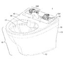
本発明は、図1に示すトイレ装置1に関する。
The present invention relates to a
本実施形態において、トイレ装置1は、ボウル10及びタンク101(図1では、これらは宙に浮いている)を備える。
In the present embodiment, the
ボウル10は、座面18と、平面をなす底面12と、2つの側壁19と、室の壁に固定される後鉛直部13とを有する。
The
室の壁にボウル10が固定された状態で、座面18は、床と略平行になるように位置する。
In a state where the
ボウル10は、液体を受けるボウル凹状部11と、該ボウル10を洗浄するために洗浄水(洗浄液)をボウル10内に吐出する吐出部16とを有する。
The
また、ボウル10は、後鉛直部13の近傍に、洗浄装置100を受け入れる凹部15を更に有する。
The
図2〜図4に示すように、洗浄装置100は、タンク101を有する。このタンク101が設置された状態で、タンク101の底面が、ボウル凹状部11の底面と同じ高さ位置にあるか、又は、ボウル凹状部11の底面よりも下側に位置する。
As shown in FIGS. 2 to 4, the
後述するように、このことが本発明の重要な特徴である。 As will be described later, this is an important feature of the present invention.
また、タンク101が設置された状態で、タンク101の上部が、ボウル10の座面18と略同じ高さ位置に位置していてもよい。
Further, the upper portion of the
タンク101は、液体の貯溜に適したポリマー製であってもよく、2つの側壁19間においてボウル10の後鉛直部13と一体形成されていてもよい。
The
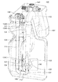
図2に示すように、タンク101内の上部には、加圧水を供給するための供給弁120が固定されている。供給弁120は、加圧水を排出導管110へと供給する。排出導管110はU字形をなしており、下降管部(下降部)111と、屈曲管部(屈曲部)112と、上昇管(柱状管)114とを有する。
As shown in FIG. 2, a
柱状管114の出口には、排出屈曲部115が位置している。図3に詳細に示すように、排出導管110における屈曲部112と柱状管114との間に、ベンチュリ管130が位置している。
A discharge bent
ベンチュリ管130は、管状のスリーブ131を有する。このスリーブ131は、その一方において、屈曲部112の断面と類似の断面を有する。また、スリーブ131は、柱状管114内に向けて開口する円錐形の狭窄部132を有する。
The
本実施形態では、スリーブ131には、4つのフィン133が固定されている。柱状管114は、排出導管110の内外を連通する円筒状の開口134が形成されるように、4つのフィン133に支持されている。
In the present embodiment, four
供給弁120は、手動の多量洗浄アクチュエータ及び少量洗浄アクチュエータにより駆動される機械式アクチュエータ125により確実に作動制御される。
The
機械式アクチュエータ125は、下降ロッド126に固定された少量洗浄フロート128と、柱状管114上及び該ロッド126上を摺動する多量洗浄フロート127とを有していてもよい。
The
多量洗浄フロート127及び少量洗浄フロート128は、発泡スチロール、又は密度が水よりも小さい、その他の材料で形成されていてもよい。
The large amount of cleaning
ロッド126は、押圧ワッシャ126A〜126Cを有する。
The
ワッシャ126Aとワッシャ126Bとの間に、レバー121が位置している。このレバー121は、供給弁120を駆動する。
The
ワッシャ126Cは、多量洗浄フロート127の近傍に位置する。
The
多量洗浄フロート127は、屈曲部112の壁部に配置された磁石129と連係するようになされている。
The large quantity of cleaning
また、洗浄装置100は、図4に示すように、注入弁140を有する。
Moreover, the washing | cleaning
注入弁140は、水による洗浄動作の後にタンク101への注水を許容する。
The
この目的のために、注入弁140は、加圧水を供給する給水ネットワークに接続されている。
For this purpose, the
図5に示すように、供給弁120及び注入弁140は、三方弁180により前記給水ネットワークに接続される。
As shown in FIG. 5, the
三方弁180は、タンク101から洗浄水を排出中に供給弁120に加圧水を連続して供給し、その後に、タンク101に注水する(タンク101を満水にする)ために、注入弁140に加圧水を供給する。
The three-
支柱142に摺動可能に設けられた注水フロート141が、注入弁140を閉鎖する。
A
以下、本発明に係るトイレ装置1の動作を説明する。
Hereinafter, operation | movement of the
以下の説明は、タンク101が満水の状態から始まるものとする。
In the following description, it is assumed that the
少量洗浄アクチュエータが始動すると、供給弁120を開放するべくワッシャ126Bがレバー121に圧力を付与するように、ロッド126が移動する。
When the small amount washing actuator is started, the
続いて、洗浄水に浸かっている少量洗浄フロート128が、ロッド126に圧力を付与して、レバー121からの力に抗してワッシャ126Bを保持する。
Subsequently, a small amount of the
多量洗浄アクチュエータが始動すると、多量洗浄フロート127が、磁石129から離れる。
When the mass cleaning actuator starts, the
洗浄水に浸かっている多量洗浄フロート127は、磁石129から離れた後、ロッド126のワッシャ126Cに圧力を付与する。これにより、ロッド126が移動して、ワッシャ126Bがレバー121を押圧して、供給弁120を開放しかつ開放状態に維持する。
The large amount of cleaning
いずれのアクチュエータが始動しても、供給弁120からの加圧水がベンチュリ管130内を流れるときに、狭窄部132により加圧水の流速が局所的に上昇する。加圧水は、狭窄部132から柱状管114へと噴出する際に、流速の上昇に応じて大きく膨張し、この膨張により、周囲の液体を吸引する力が発生する。開口134は、タンク101内の洗浄水が柱状管114へと流入するのを許容する。このように、加圧水が流れている間、ベンチュリ管130により発生した吸引力により、タンク101内の洗浄水が柱状管114へと流入する。
Regardless of which actuator is started, when the pressurized water from the
柱状管114内に吸引された洗浄水は、排出屈曲部115及び吐出部16を経由して、ボウル10のボウル凹状部11へと排出される。
The washing water sucked into the
排出屈曲部115は、洗浄水がボウル凹状部11に排出されている間、該洗浄水を適切な方向に向けて流すようにするものである。
The
本実施形態において、供給弁120は、給水ネットワークに接続されていて、加圧水を排出導管110に供給する。給水弁120からの加圧水は、約3バールの圧力を有している。
In the present embodiment, the
少量洗浄の場合には、タンク101の水位が、少量洗浄フロート128が完全に水没しないような水位となったときに、少量洗浄フロート128がロッド126に圧力を付与しなくなり、これにより、ワッシャ126Aが、重力により、レバー121の位置を変える。この結果、給水弁120が閉鎖される。
In the case of a small amount of washing, when the water level in the
多量洗浄の場合には、タンク101の水位が、多量洗浄フロート127が完全に水没しないような水位になったときに、多量洗浄フロート127の磁石129に対する位置が変わるとともに、ワッシャ126Aが、重力により、レバー121の位置を変える。この結果、給水弁120が閉鎖される。
In the case of a large amount of washing, when the water level in the
洗浄後にタンク101に注水するために、注入弁140は、注水フロート141が注入弁140を閉鎖させるように作動するまで、開放し続ける。
In order to inject water into the
したがって、本発明のトイレ装置によると、ボウルの後側又はボウルよりも下側の位置にタンクを配置可能とする利点を有する。これにより、コンパクト化されたトイレ装置が実現可能となる。また、前記洗浄装置の構成によると、ボウルへの液漏れを防止することができる。 Therefore, according to the toilet apparatus of the present invention, there is an advantage that the tank can be arranged at a position behind the bowl or below the bowl. Thereby, a compact toilet device can be realized. Moreover, according to the structure of the said washing | cleaning apparatus, the liquid leak to a bowl can be prevented.
Claims (14)
加圧水を供給する給水ネットワークに接続され、前記ボウル(10)に開口する柱状管(114)と、
前記給水ネットワークと前記柱状管(114)との間に介在されたベンチュリ管であって、前記タンク(101)内の洗浄液を前記ボウル(10)内に排出させるために、前記加圧水を膨張させて該洗浄液を吸引するように、前記タンク(101)内の略底部に配置されたベンチュリ管(130)と、
前記加圧水の前記排出手段への流入を制御する手動トリガーアクチュエータ及びロッド(126)に接続された、少なくとも1つの多量洗浄フロート(127)又は少なくとも1つの少量洗浄フロート(128)と、
を備えていることを特徴とするトイレ装置(1)。 A bowl (10), a cleaning device (100) having a tank (101) capable of storing a cleaning liquid and provided with a discharge means for discharging the cleaning liquid, and provided in parallel with the bowl (10); A toilet device (1) comprising
A columnar tube (114) connected to a water supply network for supplying pressurized water and opening into the bowl (10);
A venturi pipe interposed between the water supply network and the columnar pipe (114), wherein the pressurized water is expanded to discharge the cleaning liquid in the tank (101) into the bowl (10). A venturi tube (130) disposed substantially at the bottom of the tank (101) so as to suck the cleaning liquid;
At least one large flush float (127) or at least one minor flush float (128) connected to a manual trigger actuator and rod (126) that controls the flow of the pressurized water into the discharge means;
A toilet device (1) characterized by comprising:
前記多量洗浄フロート(127)は、前記加圧水の前記排出手段への流入を制御する前記手動トリガーアクチュエータに接続された磁石(129)により保持されることを特徴とするトイレ装置(1)。 In the toilet device (1) according to claim 1,
The toilet apparatus (1), wherein the large-scale washing float (127) is held by a magnet (129) connected to the manual trigger actuator that controls inflow of the pressurized water into the discharge means.
前記ロッド(126)は、前記加圧水の前記排出手段への流入を制御するために前記多量洗浄フロート(127)が該ロッド(126)に圧力を付与することを可能にするワッシャ(126C)を有することを特徴とするトイレ装置(1)。 In the toilet device (1) according to claim 1 or 2,
The rod (126) has a washer (126C) that allows the bulk wash float (127) to apply pressure to the rod (126) to control the flow of pressurized water into the discharge means. Toilet device (1) characterized by the above.
前記少量洗浄フロート(128)は、前記加圧水の前記排出手段への流入を制御する前記ロッド(126)に固定されていることを特徴とするトイレ装置(1)。 In the toilet device (1) according to any one of claims 1 to 3,
The toilet apparatus (1), wherein the small-quantity washing float (128) is fixed to the rod (126) that controls the flow of the pressurized water into the discharge means.
前記ロッド(126)は、前記加圧水の前記排出手段への流入を制御することを可能にする2つのワッシャ(126A,126B)を有することを特徴とするトイレ装置(1)。 In the toilet device (1) according to any one of claims 1 to 4,
Toilet device (1), characterized in that the rod (126) has two washers (126A, 126B) which allow to control the flow of the pressurized water into the discharge means.
前記ベンチュリ管(130)は、
前記柱状管(114)の前記給水ネットワーク側の端部に挿入されかつ狭窄部(132)が形成されたスリーブ(131)と、
前記洗浄液を前記柱状管(114)内に流入させるために、前記洗浄液を、前記排出手段内を流れる前記加圧水に連通させるための開口(134)と、
を有することを特徴とするトイレ装置(1)。 In the toilet device (1) according to any one of claims 1 to 5,
The venturi tube (130) is
A sleeve (131) inserted into an end of the columnar pipe (114) on the water supply network side and formed with a constricted part (132);
An opening (134) for communicating the cleaning liquid with the pressurized water flowing through the discharge means in order to allow the cleaning liquid to flow into the columnar pipe (114);
A toilet device (1) characterized by comprising:
前記柱状管(114)は、前記洗浄液を前記加圧水に連通させるための開口(134)を前記スリーブ(131)と共に画定するラッパ状拡管部を有することを特徴とするトイレ装置(1)。 In the toilet device (1) according to claim 6,
The toilet apparatus (1), wherein the columnar pipe (114) has a trumpet-shaped expanded pipe portion that defines an opening (134) for communicating the cleaning liquid with the pressurized water together with the sleeve (131).
前記スリーブ(131)には、前記柱状管(114)を保持するための少なくとも3つのフィン(133)が設けられていることを特徴とするトイレ装置(1)。 In the toilet device (1) according to claim 6 or 7,
The toilet device (1), wherein the sleeve (131) is provided with at least three fins (133) for holding the columnar tube (114).
前記排出手段は、前記給水ネットワークに接続されたU字形の排出導管(110)を有し、
前記排出導管(110)は、下降部(111)と、屈曲部(112)と、前記ベンチュリ管(130)と、前記柱状管(114)とを有することを特徴とするトイレ装置(1)。 In the toilet device (1) according to any one of claims 1 to 8,
The discharge means comprises a U-shaped discharge conduit (110) connected to the water supply network;
The toilet device (1), wherein the discharge conduit (110) includes a descending portion (111), a bent portion (112), the venturi tube (130), and the columnar tube (114).
前記給水ネットワークに接続された少なくとも1つの供給弁(120)が、前記排出手段に接続されていることを特徴とするトイレ装置(1)。 In the toilet device (1) according to any one of claims 1 to 9,
Toilet device (1), characterized in that at least one supply valve (120) connected to the water supply network is connected to the discharge means.
前記給水ネットワークに接続されかつ前記タンク(101)内に前記洗浄液としての水を注入するための少なくとも1つの注入弁(140)が設けられていることを特徴とするトイレ装置(1)。 In the toilet device (1) according to any one of claims 1 to 10,
Toilet device (1), characterized in that at least one injection valve (140) connected to the water supply network and for injecting water as the cleaning liquid into the tank (101) is provided.
前記ボウル(10)は、ボウル凹状部(11)が設けられた前部と、前記洗浄装置(100)が挿入される凹部(15)を画定する2つの側壁(19)が設けられた後部とを有することを特徴とするトイレ装置(1)。 In the toilet device (1) according to any one of claims 1 to 11,
The bowl (10) has a front part provided with a bowl concave part (11) and a rear part provided with two side walls (19) that define a concave part (15) into which the cleaning device (100) is inserted. A toilet device (1) characterized by comprising:
前記洗浄装置(100)の底面が、前記ボウル凹状部(11)の底面と同じ高さ位置にあるか、又は、該ボウル凹状部(11)の底面よりも下側に位置していることを特徴とするトイレ装置(1)。 In the toilet device (1) according to claim 12,
The bottom surface of the cleaning device (100) is at the same height as the bottom surface of the bowl concave portion (11), or is located below the bottom surface of the bowl concave portion (11). Characteristic toilet device (1).
前記洗浄装置(100)は、前記ボウル(10)の後部において、前記2つの側壁(19)の間でかつ該ボウル(10)の座面(18)と該ボウル(10)の底面(12)との間に収容されていることを特徴とするトイレ装置(1)。 In the toilet device (1) according to claim 12 or 13,
The cleaning device (100) is arranged at the rear part of the bowl (10) between the two side walls (19) and the seating surface (18) of the bowl (10) and the bottom surface (12) of the bowl (10). A toilet device (1) characterized in that it is housed between the two.
Applications Claiming Priority (3)
| Application Number | Priority Date | Filing Date | Title |
|---|---|---|---|
| FR14/57506 | 2014-08-01 | ||
| FR1457506A FR3024475B1 (en) | 2014-08-01 | 2014-08-01 | TOILET DEVICE |
| PCT/EP2015/067829 WO2016016471A1 (en) | 2014-08-01 | 2015-08-03 | Device for toilets |
Publications (1)
| Publication Number | Publication Date |
|---|---|
| JP2017523332A true JP2017523332A (en) | 2017-08-17 |
Family
ID=52737142
Family Applications (1)
| Application Number | Title | Priority Date | Filing Date |
|---|---|---|---|
| JP2017526019A Pending JP2017523332A (en) | 2014-08-01 | 2015-08-03 | Toilet equipment |
Country Status (11)
| Country | Link |
|---|---|
| US (1) | US20170254058A1 (en) |
| EP (1) | EP3194670B1 (en) |
| JP (1) | JP2017523332A (en) |
| AU (1) | AU2015295219A1 (en) |
| BR (1) | BR112017001985A2 (en) |
| EA (1) | EA039580B1 (en) |
| ES (1) | ES2913068T3 (en) |
| FR (1) | FR3024475B1 (en) |
| PL (1) | PL3194670T3 (en) |
| PT (1) | PT3194670T (en) |
| WO (1) | WO2016016471A1 (en) |
Cited By (2)
| Publication number | Priority date | Publication date | Assignee | Title |
|---|---|---|---|---|
| JP2019173315A (en) * | 2018-03-27 | 2019-10-10 | Toto株式会社 | Flush toilet bowl |
| WO2022108182A1 (en) * | 2020-11-17 | 2022-05-27 | 주식회사 토디이노베이션 | Direct flush toilet |
Families Citing this family (4)
| Publication number | Priority date | Publication date | Assignee | Title |
|---|---|---|---|---|
| JP7415302B2 (en) | 2020-02-17 | 2024-01-17 | Toto株式会社 | flush toilet |
| EP4095323B1 (en) | 2021-05-28 | 2023-12-27 | Geberit International AG | Flushing system |
| EP4095324A1 (en) * | 2021-05-28 | 2022-11-30 | Geberit International AG | Flushing system |
| EP4095325A1 (en) | 2021-05-28 | 2022-11-30 | Geberit International AG | Filling valve |
Citations (5)
| Publication number | Priority date | Publication date | Assignee | Title |
|---|---|---|---|---|
| US4918763A (en) * | 1989-01-23 | 1990-04-24 | Canaceramic Limited | Water closet with supplemented rim wash water flow |
| JPH0544239A (en) * | 1991-08-14 | 1993-02-23 | Matsushita Electric Works Ltd | Ball tap for water storage tank |
| JPH09316962A (en) * | 1996-05-24 | 1997-12-09 | Yasuo Suzuki | Drainage equipment of water storage tank for toilet operated by electromagnet |
| JP2004156382A (en) * | 2002-11-08 | 2004-06-03 | Toto Ltd | Toilet bowl |
| JP2012528960A (en) * | 2009-05-31 | 2012-11-15 | フルーイッドマスター インコーポレイテッド | Jet-driven toilet cleaning system |
Family Cites Families (16)
| Publication number | Priority date | Publication date | Assignee | Title |
|---|---|---|---|---|
| US1730108A (en) * | 1928-10-06 | 1929-10-01 | Azone George | Air vent for siphon flush |
| US1984394A (en) * | 1932-12-22 | 1934-12-18 | Catherine T Candee | Supply and discharge mechanism for water closet tanks |
| DE621903C (en) * | 1933-01-24 | 1935-11-15 | Arnoldus Johannes Gurck Dipl I | Lifting cistern for small and full flushing |
| US2073835A (en) * | 1935-11-11 | 1937-03-16 | Walter H Finley | Flush tank apparatus |
| US2177121A (en) * | 1937-06-15 | 1939-10-24 | Scott William | Flushing device for water closets |
| FR972728A (en) * | 1941-04-04 | 1951-02-02 | Open tank flush, especially for washrooms | |
| FR1188762A (en) * | 1957-12-18 | 1959-09-25 | Improvements to flushing toilets for washrooms and other sanitary uses | |
| GB1093277A (en) * | 1963-12-06 | 1967-11-29 | Shires & Company London Ltd | Improvements relating to w.c. flushing systems |
| US3851338A (en) * | 1971-11-19 | 1974-12-03 | V Roosa | Flushing device |
| US6263520B1 (en) * | 1999-02-04 | 2001-07-24 | Shin Woo Watos Co., Ltd. | Water discharging system for toilet |
| EP1134322A4 (en) * | 1999-09-27 | 2003-05-02 | Toto Ltd | Water closet and flushing water feed device |
| NL1014502C1 (en) * | 2000-02-25 | 2001-08-28 | Willem Hamelynck | Water closet flush system, requires no mechanically operated piston chamber as short jet of new water starts siphoning action |
| EP2045406A1 (en) * | 2007-10-04 | 2009-04-08 | Hermann Isenmann | Toilet cistern with additional water injection and method for emptying |
| US7975324B2 (en) * | 2008-07-30 | 2011-07-12 | Sloan Valve Company | Pressurized dual flush system |
| JP6341460B2 (en) * | 2012-10-18 | 2018-06-13 | Toto株式会社 | Flush toilet equipment |
| US9745731B2 (en) * | 2013-08-12 | 2017-08-29 | Toto Ltd. | Flush toilet apparatus |
-
2014
- 2014-08-01 FR FR1457506A patent/FR3024475B1/en active Active
-
2015
- 2015-08-03 EA EA201790245A patent/EA039580B1/en unknown
- 2015-08-03 US US15/501,077 patent/US20170254058A1/en not_active Abandoned
- 2015-08-03 PL PL15745205T patent/PL3194670T3/en unknown
- 2015-08-03 WO PCT/EP2015/067829 patent/WO2016016471A1/en active Application Filing
- 2015-08-03 EP EP15745205.3A patent/EP3194670B1/en active Active
- 2015-08-03 JP JP2017526019A patent/JP2017523332A/en active Pending
- 2015-08-03 AU AU2015295219A patent/AU2015295219A1/en not_active Abandoned
- 2015-08-03 BR BR112017001985A patent/BR112017001985A2/en not_active Application Discontinuation
- 2015-08-03 PT PT157452053T patent/PT3194670T/en unknown
- 2015-08-03 ES ES15745205T patent/ES2913068T3/en active Active
Patent Citations (5)
| Publication number | Priority date | Publication date | Assignee | Title |
|---|---|---|---|---|
| US4918763A (en) * | 1989-01-23 | 1990-04-24 | Canaceramic Limited | Water closet with supplemented rim wash water flow |
| JPH0544239A (en) * | 1991-08-14 | 1993-02-23 | Matsushita Electric Works Ltd | Ball tap for water storage tank |
| JPH09316962A (en) * | 1996-05-24 | 1997-12-09 | Yasuo Suzuki | Drainage equipment of water storage tank for toilet operated by electromagnet |
| JP2004156382A (en) * | 2002-11-08 | 2004-06-03 | Toto Ltd | Toilet bowl |
| JP2012528960A (en) * | 2009-05-31 | 2012-11-15 | フルーイッドマスター インコーポレイテッド | Jet-driven toilet cleaning system |
Cited By (3)
| Publication number | Priority date | Publication date | Assignee | Title |
|---|---|---|---|---|
| JP2019173315A (en) * | 2018-03-27 | 2019-10-10 | Toto株式会社 | Flush toilet bowl |
| JP7435675B2 (en) | 2018-03-27 | 2024-02-21 | Toto株式会社 | flush toilet |
| WO2022108182A1 (en) * | 2020-11-17 | 2022-05-27 | 주식회사 토디이노베이션 | Direct flush toilet |
Also Published As
| Publication number | Publication date |
|---|---|
| AU2015295219A1 (en) | 2017-02-23 |
| BR112017001985A2 (en) | 2018-03-06 |
| EP3194670A1 (en) | 2017-07-26 |
| PL3194670T3 (en) | 2022-06-06 |
| EA039580B1 (en) | 2022-02-14 |
| ES2913068T3 (en) | 2022-05-31 |
| PT3194670T (en) | 2022-05-13 |
| FR3024475A1 (en) | 2016-02-05 |
| US20170254058A1 (en) | 2017-09-07 |
| WO2016016471A1 (en) | 2016-02-04 |
| FR3024475B1 (en) | 2016-11-25 |
| EA201790245A1 (en) | 2017-06-30 |
| EP3194670B1 (en) | 2022-02-16 |
Similar Documents
| Publication | Publication Date | Title |
|---|---|---|
| JP2017523332A (en) | Toilet equipment | |
| JP5823381B2 (en) | Jet-driven toilet cleaning system | |
| JP2012528959A5 (en) | ||
| BRPI0904218A2 (en) | two stroke foam pump | |
| US20130111657A1 (en) | Switching device for rim water in low tank toilet | |
| JP4517394B2 (en) | Accumulation device, flush toilet equipped with the same, lifting device, and soap dispenser | |
| JP2009500546A (en) | Detergent dispenser for flush tank | |
| US20180044902A1 (en) | Liquid Chemical Dispensing Apparatus for Toilet Bowls with Remote Liquid Reservoir | |
| JP2018520280A5 (en) | ||
| JP6187759B2 (en) | Flush toilet equipment | |
| US20150033463A1 (en) | Flushing system for a pressurized toilet | |
| JP5462989B2 (en) | Bowl tilting toilet | |
| JP2015068121A5 (en) | ||
| JP5906437B2 (en) | Toilet device | |
| JP2007215873A (en) | Liquid soap supply device | |
| EP2765247B1 (en) | A siphonic flushing device | |
| US3362030A (en) | Water closet | |
| JP7296544B2 (en) | bathroom cleaning equipment | |
| CN212248555U (en) | Water supply device and toilet stool | |
| US2285073A (en) | Water closet flushing apparatus | |
| JP2016217101A (en) | Siphon jet type toilet bowl device | |
| US826001A (en) | Flushing-tank. | |
| JP6168299B2 (en) | Flush toilet equipment | |
| US2526382A (en) | Water displacer starter for outlet siphons | |
| JP2023034492A (en) | Washing water tank device and flush toilet bowl device comprising the same |
Legal Events
| Date | Code | Title | Description |
|---|---|---|---|
| A621 | Written request for application examination |
Free format text: JAPANESE INTERMEDIATE CODE: A621 Effective date: 20180711 |
|
| A977 | Report on retrieval |
Free format text: JAPANESE INTERMEDIATE CODE: A971007 Effective date: 20190719 |
|
| A131 | Notification of reasons for refusal |
Free format text: JAPANESE INTERMEDIATE CODE: A131 Effective date: 20190730 |
|
| A601 | Written request for extension of time |
Free format text: JAPANESE INTERMEDIATE CODE: A601 Effective date: 20191024 |
|
| RD01 | Notification of change of attorney |
Free format text: JAPANESE INTERMEDIATE CODE: A7426 Effective date: 20191024 |
|
| A521 | Request for written amendment filed |
Free format text: JAPANESE INTERMEDIATE CODE: A821 Effective date: 20191024 |
|
| A02 | Decision of refusal |
Free format text: JAPANESE INTERMEDIATE CODE: A02 Effective date: 20200407 |