JP2017515704A - Printing on cylindrical objects - Google Patents
Printing on cylindrical objects Download PDFInfo
- Publication number
- JP2017515704A JP2017515704A JP2016564986A JP2016564986A JP2017515704A JP 2017515704 A JP2017515704 A JP 2017515704A JP 2016564986 A JP2016564986 A JP 2016564986A JP 2016564986 A JP2016564986 A JP 2016564986A JP 2017515704 A JP2017515704 A JP 2017515704A
- Authority
- JP
- Japan
- Prior art keywords
- print head
- holding device
- cylindrical object
- path
- Prior art date
- Legal status (The legal status is an assumption and is not a legal conclusion. Google has not performed a legal analysis and makes no representation as to the accuracy of the status listed.)
- Pending
Links
Images


Classifications
-
- B—PERFORMING OPERATIONS; TRANSPORTING
- B41—PRINTING; LINING MACHINES; TYPEWRITERS; STAMPS
- B41J—TYPEWRITERS; SELECTIVE PRINTING MECHANISMS, i.e. MECHANISMS PRINTING OTHERWISE THAN FROM A FORME; CORRECTION OF TYPOGRAPHICAL ERRORS
- B41J3/00—Typewriters or selective printing or marking mechanisms characterised by the purpose for which they are constructed
- B41J3/407—Typewriters or selective printing or marking mechanisms characterised by the purpose for which they are constructed for marking on special material
- B41J3/4073—Printing on three-dimensional objects not being in sheet or web form, e.g. spherical or cubic objects
- B41J3/40733—Printing on cylindrical or rotationally symmetrical objects, e. g. on bottles
Abstract
円筒形の物体(31)を印刷するための装置は、複数の印刷ヘッド(32)と、使用時に、物体を印刷ヘッドの間に移動させるように印刷ヘッド(32)に対して移動可能な少なくとも1個の保持デバイスとを備える。少なくとも1個の保持デバイスの経路は、互いに水平方向にオフセットする複数の垂直部分(34)を有する。それぞれの垂直部分(34)は、互いに垂直方向にずれて配置され、片方がもう片方よりも直接的に上にくるように配置された少なくとも2個の同一の配置された印刷ヘッド(32)を備える。少なくとも1個の保持デバイスは、印刷ヘッドの間のその経路の一部または全てが垂直であるように、少なくとも2個の印刷ヘッド(32)の間に物体(31)を移動させる。An apparatus for printing a cylindrical object (31) includes at least a plurality of print heads (32) and, in use, movable relative to the print head (32) to move the object between the print heads. One holding device. The path of the at least one holding device has a plurality of vertical portions (34) that are horizontally offset from each other. Each vertical portion (34) has at least two identically arranged print heads (32) arranged vertically offset from each other and arranged so that one is directly above the other. Prepare. At least one holding device moves the object (31) between the at least two print heads (32) such that part or all of its path between the print heads is vertical.
Description
本発明は、印刷装置に関し、さらに特定的には、缶または瓶のような実質的に円筒形の物体に印刷するために設計された装置に関する。 The present invention relates to printing devices, and more particularly to devices designed for printing on substantially cylindrical objects such as cans or bottles.
WO 93/11866号に記載される種類の静電式プリンターは、固体粒子をまず凝縮し、次いで吐出するための電場を加えることによって、化学的に不活性な絶縁性担体液に分散した帯電固体粒子を吐出する。1個の印刷ヘッドは、典型的には、多くの吐出部を備えており、それぞれの吐出部が、吐出位置に印加される電圧に依存して、所定体積のインクを吐出するようにすることができる。 An electrostatic printer of the type described in WO 93/11866 is a charged solid dispersed in a chemically inert insulating carrier liquid by first condensing solid particles and then applying an electric field for ejection. Discharge particles. One print head typically includes a number of ejection units, and each ejection unit ejects a predetermined volume of ink depending on the voltage applied to the ejection position. Can do.
種々の印刷ヘッドの設計は、当該技術分野で記載されており、例えば、WO 93/11866号、WO 97/27058号、WO 97/27056号、WO 98/32609号、WO 98/42515号、WO 01/30576号およびWO 03/101741号に記載されているものがある。 Various printhead designs have been described in the art, for example, WO 93/11866, WO 97/27058, WO 97/27056, WO 98/32609, WO 98/42515, WO Some are described in 01/30576 and WO 03/101741.
印刷ヘッドからの一定量のインク吐出を達成するために、吐出位置でのインクの静止圧を正確に制御することが必要である。インクの圧力は、堰き止め部分を有し、印刷ヘッドを供給する容器、インクの合計深さを決定付ける堰き止め部分の頂部と吐出位置との高さの差、すなわち、重力に起因する圧力を用いることによって、空気圧と重力の組み合わせによって制御されてもよい。吐出部が異なる高さに存在する印刷ヘッドは、その長さ方向に沿ってさまざまなインク圧を受け、吐出性能が対応して変動するだろう。 In order to achieve a certain amount of ink ejection from the print head, it is necessary to accurately control the static pressure of the ink at the ejection position. The pressure of the ink has a damming portion, a container that supplies the print head, the height difference between the top of the damming portion that determines the total ink depth and the ejection position, that is, the pressure due to gravity. By using, it may be controlled by a combination of air pressure and gravity. Print heads with different ejection heights will experience various ink pressures along their length and the ejection performance will vary correspondingly.
円筒形の物体に印刷するために、吐出部が物体の長手方向の軸に平行に配置されるように1個以上の印刷ヘッドが並べられてもよく、次いで、印刷ヘッドが物体表面に一連の液滴を吐出するときに、物体の長手方向の軸に沿って回転してもよく、これにより物体の上に画像が作られる。 In order to print on a cylindrical object, one or more print heads may be arranged such that the discharge is arranged parallel to the longitudinal axis of the object, and then the print head When ejecting a droplet, it may rotate along the longitudinal axis of the object, thereby creating an image on the object.
US 2011/0232514 A1号は、瓶が水平面に運ばれ、瓶の長手方向の軸が、印刷中に垂直に維持される、瓶に印刷するための装置を開示する。1個の静電式印刷ヘッドが、瓶と実質的に同じ経路に沿って移動しつつ、それぞれの瓶に印刷する。 US 2011/0232514 A1 discloses an apparatus for printing on a bottle in which the bottle is carried in a horizontal plane and the longitudinal axis of the bottle is kept vertical during printing. One electrostatic print head prints on each bottle while moving along substantially the same path as the bottle.
この印刷装置の幾何形状は、それぞれの印刷ヘッドが、垂直軸に沿って配置された吐出位置と共に並ぶような幾何形状であることを必要とする。異なる吐出位置の間に、おそらく圧力勾配が存在し、高品質の画像を生成するために、複雑なインク供給装置および較正プロセスを必要とするだろう。 The geometry of this printing device requires that each print head be aligned with the ejection positions arranged along the vertical axis. There will probably be pressure gradients between the different ejection positions, which will require complex ink supply and calibration processes to produce high quality images.
WO 2012/147612 A1号は、缶と印刷ヘッドが垂直面を一緒に移動しながら、缶が多くの印刷ヘッドによって印刷される印刷装置を開示する。 WO 2012/147612 A1 discloses a printing device in which cans are printed by many print heads, while the cans and print heads move together in a vertical plane.
ここに開示される印刷ヘッドの複数の向きは、円形の運動に従うときに、さらに促進力を受け、おそらく、高品質の画像を生成するために、複雑なインク供給装置および構成プロセスを必要とする。 The multiple orientations of the print head disclosed herein are further accelerated when following a circular motion and probably require complex ink supply and configuration processes to produce high quality images. .
US 2013/0269551 A1号は、主要な軸を垂直に有する担体に取り付けられた瓶または缶が、印刷ステーションの間を水平に移動する印刷装置を開示する。印刷ステーションは、瓶または缶に対して垂直に移動し、互いに近傍に内向きおよび外向きになる。 US 2013/0269551 A1 discloses a printing device in which a bottle or can attached to a carrier having a main axis vertically moves horizontally between printing stations. The printing station moves perpendicular to the bottle or can and is inward and outward in the vicinity of each other.
この装置も、垂直に並べられた吐出部を備えており、上述の欠点が問題となるだろう。 This device also has discharge units arranged vertically, and the above-mentioned drawbacks will be a problem.
WO 2012/131478 A2号は、円筒形の物体が、複数の印刷ヘッドステーションを備える1個の垂直方向の経路に沿って保持デバイスによって運ばれる印刷装置を開示する。 WO 2012/131478 A2 discloses a printing apparatus in which a cylindrical object is carried by a holding device along a single vertical path comprising a plurality of print head stations.
US 6,769,357 B1号は、缶が、一連の印刷ヘッドステーションの間の実質的に円形の経路を通って運ばれる缶印刷装置を開示する。この装置は、異なる方を向いた印刷ヘッドを備える多くの印刷ヘッドステーションを開示する。このようなシステムは、種々の吐出位置で正しいインク圧力を維持するために複雑なインク供給システムを必要とするだろう。 US 6,769,357 B1 discloses a can printing device in which cans are carried through a substantially circular path between a series of printhead stations. This apparatus discloses a number of printhead stations with printheads facing in different directions. Such a system would require a complex ink supply system to maintain the correct ink pressure at various ejection locations.
さらに、多くの場合に、物体を1回回転させる間に1個の印刷ヘッドによって画像全体を作成することはできない。このことは、例えば、画像が数種類の色で作られ、それぞれの色が異なる印刷ヘッドによって印刷されなければならない場合に当てはまるだろう。このことは、望ましい印刷解像度または印刷密度を達成するために、それぞれの吐出部が、物体を何回か通過することが必要な場合にも当てはまるだろう。また、物体の長手方向の長さが1個の印刷ヘッドの幅よりも大きい場合には、表面全体に及ぶには数個の印刷ヘッドが配置されることが必要であろう。または、同じ印刷ヘッドが、物体に対して数回通過するように移動してもよい。 Furthermore, in many cases, it is not possible to create an entire image with one print head while rotating the object once. This may be the case, for example, when an image is made up of several colors, each of which has to be printed by a different print head. This may also be the case when each dispenser needs to pass several times through the object to achieve the desired print resolution or print density. Also, if the length of the object in the longitudinal direction is greater than the width of a single print head, it may be necessary to arrange several print heads to cover the entire surface. Alternatively, the same print head may move so that it passes through the object several times.
このような、一般的に1回の通過中に1個のインクジェット印刷ヘッドが円筒形の物体に完全な画像を作成することができないことは、円筒形の物体に印刷することができる速度を制限する1つの因子である。他の制限する因子は、1個の印刷ヘッドが印刷することができる最大速度であり、この速度は、一般的に、使用する印刷ヘッドの種類に特徴的な固定された値であり、速くはならないだろう。 This inability of one inkjet print head to produce a complete image on a cylindrical object, typically during a single pass, limits the speed at which it can print on a cylindrical object. Is one factor. Another limiting factor is the maximum speed that a single print head can print, which is typically a fixed value characteristic of the type of print head used, It will not be.
この制限を克服し、これによって印刷システムの処理能力を上げるために、複数の印刷操作を並行して行う必要がある。このことは、同じ物体に同時に印刷する印刷ヘッドステーションの数個の印刷ヘッドによって達成されてもよく、または異なる物体に同時に印刷する数個の印刷ヘッドステーションによって達成されてもよい。一般的に、一連の印刷ヘッドステーションを有し、それぞれの印刷ヘッドステーションが、それぞれの印刷ヘッドステーションで数個の印刷ヘッドによって円筒形の物体が印刷されるように、多くの印刷ヘッドを備えることが可能である。次いで、円筒形の物体は、異なる態様の画像を異なる印刷ヘッドステーションで印刷し得るように、ある印刷ヘッドステーションから次の印刷ヘッドステーションへと運ばれてもよい。この技術を用い、因子Np×Nsによって1個の印刷ヘッドを用いことによって、同時に行う印刷操作の合計速度を速くすることができる。ここで、Npは、それぞれの印刷ヘッドステーションの印刷ヘッドの数であり、Nsは、印刷ヘッドステーションの合計数である。Nsは限定されないが、同じ物体に同時に印刷することができるように特定の数の印刷ヘッドNpを配置するための十分な空間のみが必要である。さらに、同じ円筒形の物体に印刷し得る最大数の印刷ヘッドを用いることが、必ずしも最適な配置ではないといういくつかの理由が存在する。 In order to overcome this limitation and thereby increase the throughput of the printing system, it is necessary to perform multiple printing operations in parallel. This may be achieved by several printhead stations printing simultaneously on the same object, or by several printhead stations printing simultaneously on different objects. Generally, it has a series of print head stations, each print head station having a number of print heads so that cylindrical objects are printed by several print heads at each print head station Is possible. The cylindrical object may then be transported from one print head station to the next so that different aspects of the image can be printed at different print head stations. By using this technique and using one print head with a factor N p × N s , the total speed of simultaneous printing operations can be increased. Here, N p is the number of print heads in each print head station, and N s is the total number of print head stations. N s is not limited, but only sufficient space is required to place a specific number of print heads N p so that the same object can be printed simultaneously. In addition, there are several reasons that using the maximum number of print heads that can print on the same cylindrical object is not necessarily the optimal arrangement.
複数の印刷ヘッドが、異なる方向にインクを吐出するために異なる向きを向いていると、問題が生じる。インクヘッド吐出部を供給するインク供給装置は、吐出部に対するインクの圧力と流れを正しく制御するように、所定の向きに維持されなければならない。従って、印刷ヘッドが複数の向きを向いていると、印刷ヘッドとは独立して向きを変えることが可能な、それぞれの印刷ヘッドのためのインク供給システムのもっと複雑な設計が必要となり、物理的な大きさと複雑さが増す。この配置の別の問題は、それぞれのインク供給の圧力制御が、印刷ヘッドが異なる向きに配置されたときに、インク供給と印刷ヘッド吐出部との間の変動可能な高さから生じる異なる水静止圧を与えるように独立して設定されなければならないことであり、インク供給装置の操作に複雑さが加わる。 A problem arises when multiple print heads are oriented in different directions to eject ink in different directions. The ink supply device that supplies the ink head ejection unit must be maintained in a predetermined orientation so as to correctly control the pressure and flow of ink to the ejection unit. Therefore, if the print head is oriented in multiple orientations, a more complex design of the ink supply system for each print head that can be oriented independently of the print head is required and the physical Increase in size and complexity. Another problem with this arrangement is that each ink supply pressure control results in different water quiescence resulting from the variable height between the ink supply and the printhead ejection section when the printheads are arranged in different orientations. It must be set independently to apply pressure, adding complexity to the operation of the ink supply device.
さらに、1個の印刷ヘッドの吐出部が同じ水平面に置かれない場合、それぞれの吐出位置でのインク圧はさまざまなものとなり、印刷ヘッドを通るインクの処理能力と印刷された画像の品質に影響を与える。 In addition, when the ejection parts of a single print head are not placed on the same horizontal plane, the ink pressure at each ejection position will vary, affecting the throughput of ink through the print head and the quality of the printed image. give.
印刷ヘッドが、水平方向より上に角度をつけてインクを印刷するように配置される場合、塵および他の浮遊粒子が印刷ヘッドの印刷面に溜まり、吐出の信頼性を損なうため、さらなる問題が起こる。 When the print head is arranged to print ink at an angle above the horizontal direction, dust and other airborne particles accumulate on the print surface of the print head, impairing ejection reliability, and further problems. Occur.
さらに、印刷される物体が、ある印刷ヘッドステーションから次の印刷ヘッドステーションへと運ばれることが必要であるため、それぞれの印刷ヘッドステーションの印刷ヘッドの配置が、印刷ヘッドステーションの間の物体または保持デバイスの好ましい経路を妨害しないことが望ましい。物体の円筒形表面が、印刷ヘッドによって全側面を囲まれているため、第1の印刷ヘッドステーションから物体を取り出すために保持デバイスの非常に複雑な運動が必要となり、第2の印刷ヘッドステーションに物体を配置するために別の複雑な運動が必要となり、処理能力が犠牲となり、ステーションからステーションへと印刷を正確に登録するのは非常に課題が多い。 In addition, since the object to be printed needs to be transported from one print head station to the next, the print head arrangement of each print head station is the object or holding between the print head stations. It is desirable not to interfere with the preferred path of the device. Since the cylindrical surface of the object is surrounded on all sides by the print head, a very complex movement of the holding device is required to remove the object from the first print head station, and the second print head station Accurate registration of printing from station to station is very challenging because it requires another complex movement to place the object, sacrificing processing power.
印刷ヘッドの操作の有効性を犠牲にすることなく、または印刷ヘッドステーションの間の物体の移動を不可能なものにすることなく、物体の処理能力を可能な限り大きくする印刷ヘッドおよび印刷ヘッドステーションの配置を提供する必要がある。 Print heads and print head stations that maximize the throughput of objects without sacrificing the effectiveness of print head operation or making it impossible to move objects between print head stations Need to provide a placement.
本発明は、実質的に円筒形の物体を印刷するための装置を提供する。実質的に円筒形の物体は、その長さの少なくとも一部に沿って実質的に一定の断面を有する物体であってもよい。実質的に円筒形の物体は、その長さの少なくとも一部に沿って、長手方向の軸に対して実質的に回転対称形である物体であってもよい。実質的に円筒形の物体の例としては、限定されないが、缶、瓶または管が挙げられる。 The present invention provides an apparatus for printing a substantially cylindrical object. A substantially cylindrical object may be an object having a substantially constant cross section along at least a portion of its length. A substantially cylindrical object may be an object that is substantially rotationally symmetric about a longitudinal axis along at least a portion of its length. Examples of substantially cylindrical objects include but are not limited to cans, bottles or tubes.
本発明の一実施形態は、複数の印刷ヘッドと、使用時に、物体を印刷ヘッドの間に移動させるように印刷ヘッドに対して移動可能な少なくとも1個の保持デバイスとを備え、少なくとも1個の保持デバイスの経路は、互いに水平方向にオフセットする複数の垂直部分を有し、それぞれの垂直部分は、互いに垂直方向にずれて配置され、片方がもう片方よりも直接的に上にくるように配置された少なくとも2個の同一の配置された印刷ヘッドを備え、少なくとも1個の保持デバイスは、印刷ヘッドの間のその経路の一部または全てが垂直であるように、少なくとも2個の印刷ヘッドの間に物体を移動させる。 One embodiment of the present invention comprises a plurality of print heads and at least one holding device movable relative to the print head to move an object between the print heads in use, wherein at least one holding device is provided. The path of the holding device has a plurality of vertical portions that are horizontally offset from each other, each vertical portion being arranged vertically offset from each other, with one placed directly above the other. At least two identically arranged printheads, wherein at least one holding device has at least two printheads such that part or all of its path between the printheads is vertical. Move the object in between.
印刷ヘッドのこの配置および向きによって、印刷される物体を、印刷ヘッドの近傍に向かわせ、次いで、この物体に印刷する、すでに知られている方法よりも効果的な方法が可能になる。印刷ヘッドが複数の垂直方向の経路に沿って配置されることによって、数個の個々の印刷ヘッドが、水平面に平行に置かれる吐出部アレイを有するように機能することができ、吐出部の位置の圧力分布を単純化する。さらに、それぞれの印刷ヘッドが、水平面に対して同一の向きに向けられることを明記することによって、印刷ヘッドに対するインクの正しい圧力および流速をもたらすのに必要なインク供給の設定をさらに単純化することができる。 This arrangement and orientation of the print head allows a more effective method than the already known methods in which the object to be printed is directed in the vicinity of the print head and then printed on this object. By arranging the print heads along a plurality of vertical paths, several individual print heads can function to have an ejector array placed parallel to a horizontal plane, and the location of the ejector Simplify the pressure distribution. In addition, it further simplifies the ink supply settings required to provide the correct ink pressure and flow rate to the printhead by specifying that each printhead is oriented in the same orientation relative to the horizontal plane. Can do.
複数の垂直な経路を通って移動する保持デバイスを提供することで、インク供給システムおよび印刷ヘッド較正プロセスの必要な複雑さを最低限にしつつ、大きな処理能力を与える多くの印刷システムが可能になる。1個の保持デバイスを使用し、多くの経路または垂直な経路を通って1個の円筒形の物体を運んでもよく、または、多くの円筒形の物体が連続して載せられ、取り出されるサイクルを実施してもよい。 Providing a holding device that moves through multiple vertical paths allows for many printing systems that provide significant throughput while minimizing the required complexity of the ink supply system and the printhead calibration process. . A single holding device may be used to carry a single cylindrical object through many paths or vertical paths, or a cycle in which many cylindrical objects are placed and removed in succession. You may implement.
別の実施形態において、少なくとも2個の印刷ヘッドステーションが、互いに水平方向にオフセットし、それぞれの印刷ヘッドステーションが、同じ高さにあり、互いに水平方向にずれて配置されるように配置された少なくとも2つの印刷ヘッドを備え、これによって、その間にギャップを生成し、このギャップを通って、印刷される円筒形の物体が通過し得るように配置された、複数の印刷ヘッドステーションと、使用時に、印刷ヘッドの間の経路の一部または全てが垂直であるように、物体を印刷ヘッドの間に移動させるように印刷ヘッドに対して移動可能な少なくとも1個の保持デバイスとを備える、円筒形の物体を印刷するための装置が提供される。 In another embodiment, at least two print head stations are offset horizontally from each other, and each print head station is at the same height and arranged at least offset horizontally. A plurality of printhead stations, arranged in such a way that two printheads are arranged so that a cylindrical object to be printed can pass therethrough, creating a gap therebetween, A cylindrical shape comprising at least one holding device movable relative to the print head so as to move an object between the print heads so that part or all of the path between the print heads is vertical An apparatus for printing an object is provided.
個々の物体が運ばれる垂直な経路によって、ここでも、印刷ヘッドの最適な向きが可能になり、吐出部を供給するのに必要なインク供給システムが単純化される。さらに、物体が運ばれ得るギャップの両側に印刷ヘッドを配置することで、もっと多くの印刷ヘッドが物体表面で印刷することが可能となり、行い得る並行する印刷操作の数が多くなり、従って、物体の処理能力が大きくなる。 Again, the vertical path through which the individual objects are carried allows an optimal orientation of the printhead and simplifies the ink supply system required to supply the ejection section. In addition, placing print heads on either side of the gap through which the object can be carried allows more print heads to print on the object surface, increasing the number of parallel printing operations that can be performed, and thus the object The processing capacity of
本発明の別の態様は、吐出部の直線形のアレイを有する少なくとも1個の印刷ヘッドを有し、少なくとも1個の印刷ヘッドがそれぞれ、水平面に対して同じ角度を向いている、少なくとも1個の印刷ヘッドステーションと、少なくとも1個の印刷ヘッドが円筒形の物体を印刷することができるように、円筒形の物体を保持し、円筒形の物体を少なくとも1個の印刷ヘッドステーションの近傍に移動するためのものであり、印刷するとき、円筒形の物体の長手方向の軸が吐出部アレイと平行に維持されつつ、その長手方向の軸の周りを円筒形の物体が回転するように構成されている少なくとも1個の保持デバイスとを備える、円筒形の物体を印刷するための装置を提供する。 Another aspect of the invention comprises at least one print head having a linear array of ejection sections, each of which is at the same angle with respect to a horizontal plane. Hold the cylindrical object and move the cylindrical object in the vicinity of the at least one print head station so that at least one print head can print the cylindrical object. When printing, the cylindrical object is configured so that the cylindrical object rotates about the longitudinal axis while maintaining the longitudinal axis of the cylindrical object parallel to the discharge unit array. There is provided an apparatus for printing a cylindrical object comprising at least one holding device.
これにより、吐出部のアレイが印刷中に同じ水平面に留まり、吐出位置全体でインク圧を一定に保つことができる。個々の印刷ヘッドを合わせ、複数の印刷操作を並行で行い、隣接する印刷ヘッド間で変動させる必要がない単純な較正プロセスおよびインク供給システムを有するシステムを作成してもよい。 Thereby, the array of ejection portions remains on the same horizontal plane during printing, and the ink pressure can be kept constant at the entire ejection position. Individual printheads may be combined to create a system with a simple calibration process and ink supply system that does not require multiple printing operations to be performed in parallel and varied between adjacent printheads.
本発明は、最適な印刷品質を維持しつつ、高い処理能力を可能にする、缶31または他の円筒形の物体31をデジタル印刷するための装置および方法を提供する。
The present invention provides an apparatus and method for digital printing of a
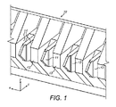
図1は、吐出部11の直線形のアレイを備え、それぞれの吐出部が、吐出位置と基材との間に電場を加えると所定体積のインクを吐出するようにすることが可能な印刷ヘッド32を示す。それぞれの吐出部11は、狭くなった先端部を有する形状であり、その周囲をインクが流れ、非常に局在化された吐出位置を与える。吐出セルは、2個の分割壁13(チーク(cheek)とも呼ばれる)によって輪郭が規定され、その間に中央直立部12が存在する。それぞれのセルにおいて、インクは、吐出直立部12のそれぞれの側面に1つずつの2つの経路14を流れ、使用時に、チークの頂部と吐出直立部の頂部の間にインクメニスカスが留まる。この幾何形状では、z軸の正の方向は、基材から印刷ヘッドに向かう(典型的には、基材と吐出先端部の最短距離に沿う)方向を示すと定義され、x軸は、吐出直立部の先端の線に沿った向きを示し、y軸は、これらに垂直な方向である。
FIG. 1 shows a print head that includes a linear array of ejection sections 11 and that each ejection section ejects a predetermined volume of ink when an electric field is applied between the ejection position and the substrate. 32. Each discharge portion 11 has a shape having a narrowed tip portion, and ink flows around the discharge portion 11 to give a highly localized discharge position. The discharge cell is defined by two dividing walls 13 (also referred to as cheeks), and a
それぞれの吐出部の向きは、その中心軸によって規定され、典型的には、図1に定義されるz軸に平行である。このような軸は、吐出先端部の中央を通っていてもよく、これに加え、またはこれに代えて、吐出先端部の対称軸に沿っていてもよく、またはこれに平行であってもよい。これに加え、またはこれに代えて、中心軸は、吐出アレイを形成する層状構造の中の1つ以上の層に沿っていてもよく、またはこれに平行であってもよく、特に、以下に記載する中央タイルに沿っていてもよく、またはこれに平行であってもよい。 The orientation of each discharge section is defined by its central axis and is typically parallel to the z-axis defined in FIG. Such an axis may pass through the center of the discharge tip, and in addition or alternatively, may be along the axis of symmetry of the discharge tip or may be parallel thereto. . In addition or alternatively, the central axis may be along or parallel to one or more layers in the layered structure forming the ejection array, in particular: It may be along or parallel to the central tile described.
典型的には、吐出アレイは、インク入口マニホルド、インク入口プリズム、中央タイルおよびインク出口マニホルドを少なくとも含む層状構造として作られる。中央タイルは、その前側の縁部に沿って作られた吐出点のアレイを有し、中央タイルとプリズムは、吐出アレイに向かうか、または吐出アレイから出るインクを供給するための流路を有する。 Typically, the ejection array is made as a layered structure that includes at least an ink inlet manifold, an ink inlet prism, a central tile, and an ink outlet manifold. The central tile has an array of ejection points made along its front edge, and the central tile and prism have a flow path for supplying ink to or from the ejection array. .
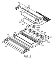
図1、図2および図3を参照すると、印刷ヘッドの本体は、流入ブロック101と流出ブロック102とを備え、これらによって、プリズム202と中央タイル201が挟まれているのがわかるだろう。中央タイル201は、その前側の縁部に沿って吐出位置または先端部のアレイ403と、その後側の縁部に沿って電気接続のアレイ203とを有する。それぞれの吐出位置403は、直立部12を備えており、インクメニスカスが(当該技術分野でよく知られている様式で)この直立部と相互作用する。直立部12のそれぞれの側面がインク流路14であり、吐出直立部12の両側を流れるインクを保有する。使用時に、所定割合のインクが吐出位置403から吐出され、例えば、印刷される画像のピクセルを形成する。
With reference to FIGS. 1, 2 and 3, it can be seen that the body of the print head comprises an
静電力を加えることによる吐出位置403からのインクの吐出は、当業者に十分に理解され、以下にさらに記載はしない。
The ejection of ink from the
プリズム202は、中央タイル201の個々の吐出位置403それぞれに対応した一連の狭い流路(図示せず)を有する。それぞれの吐出位置403のインク流路は、プリズム202のそれぞれの流路と液体が流れるように接続しており、さらに、流入ブロック101内に作られる入口マニホルドの前側部分407と液体が流れるように接続している(この入口マニホルドは、図2に示される流入ブロック101の下側に作られるため、この図に示されていない)。吐出位置403の反対側で、インク流路は、吐出位置403あたり1個の流路にまとまり、中央タイル201の下側の吐出位置403(図3に示される)から、流出ブロック102内に作られる出口マニホルド209の前側部分409と液体が流れるように接続する点まで延びている。
The prism 202 has a series of narrow flow paths (not shown) corresponding to the
インクは、流入ブロック101内の入口マニホルドにインクを供給する印刷ヘッド100内のインク供給管220によって吐出位置403に供給される。インクは、入口マニホルドを通り、入口マニホルドからプリズム202の流路を経て中央タイル201の吐出位置403へと流れる。次いで、使用時に吐出位置403から吐出されない過剰なインクは、中央タイル201のインク流路に沿って、流出ブロック102内の出口マニホルド209へと流れる。インクは、出口マニホルド209に残り、インク戻り管221を通って流れ、バルクインク供給部に戻る。
Ink is supplied to the
個々の吐出位置403で正確に制御された吐出特徴を維持するために、個々の吐出位置403に接続するプリズム202の流路には、正確な圧力で入口マニホルドからのインクが供給される。インク入口マニホルドによってプリズム202のそれぞれの個々の流路に供給される圧力は、印刷ヘッド100の吐出位置403のアレイの幅全体にわたって等しい。同様に、入口と出口のインク圧の両方が合わさって、それぞれの吐出位置403でのインクの静止圧力を決定付けるため、中央タイル201のそれぞれの個々の流路から出口マニホルド209に戻るインクの圧力は、吐出位置403のアレイの幅全体にわたって等しく、出口で正確に制御される。
In order to maintain precisely controlled ejection characteristics at each
印刷ヘッド100には、上側204および下側205の洗浄液マニホルドも提供される。上側および下側の洗浄液マニホルドは、それぞれ、入口105a、105bを有し、この入口を通り、すすぎ/洗浄液を印刷ヘッド100に供給することができる。流入ブロック101および流出ブロック102の両方にも、洗浄液経路401が備わっている。流入ブロック101内の経路は、上側の洗浄液マニホルド204と液体が流れるように接続し、流出ブロック102内の経路は、下側の洗浄液マニホルド205と液体が流れるように接続している。流体接続部206は、洗浄液マニホルドをそれぞれの洗浄液経路に連結する。
The print head 100 is also provided with an upper 204 and lower 205 cleaning fluid manifold. The upper and lower cleaning fluid manifolds each have an
流入ブロックおよび流出ブロックの中の洗浄液経路401は、洗浄液出口207で終わっている。吐出位置403に向かう経路は、基準プレート104と、流入ブロック101と流出ブロック12の外側表面との中にあるV字型の空洞402によって規定される閉じられた空間405に沿って続き、吐出位置403自体が空洞402の中に存在する位置に至る。このV字型の空洞の2つの側面は、この例では、互いに90度になっている。
The cleaning
印刷ヘッドの前側で、中間電極プレートが基準プレートに取り付けられ、次いで、印刷ヘッドの本体に取り付けられていることがわかるだろう。図3において、中間電極は、それぞれの吐出部先端部の中心軸に垂直になっていることがわかるだろう。このとき、中間電極は、印刷ヘッドの平坦な印刷面を形成し、その向きは、吐出部先端部の向きによって規定される。従って、吐出部先端部の軸が水平面に存在するような方向に印刷ヘッドを向けることによって、中間電極を垂直方向に向けることができ、それによって、保持される物体は、印刷されるのに十分に近い距離で、垂直な経路の中の印刷ヘッドを通過することができる。 It will be seen that on the front side of the print head, the intermediate electrode plate is attached to the reference plate and then to the body of the print head. In FIG. 3, it can be seen that the intermediate electrode is perpendicular to the central axis of the tip of each discharge section. At this time, the intermediate electrode forms a flat print surface of the print head, and the direction thereof is defined by the direction of the tip of the discharge unit. Therefore, by directing the print head in a direction such that the axis of the discharge tip is in the horizontal plane, the intermediate electrode can be oriented vertically, so that the object being held is sufficient to be printed. Can pass through the print head in a vertical path at a distance close to.
図4は、入口管24を通って離れた位置(図示せず)からインク23が供給されるインク容器20を示す。インクは、印刷ヘッド(図示せず)に向かう出口管25を介し、容器底部から出る。容器20には、堰き止め部分22が配置されており、堰き止め部分22は、容器を第1のチャンバと第2のチャンバに分割する。インク23は、堰き止め部分22の頂部の高さに達するまで、入口管24を通って第1のチャンバに圧送され、堰き止め部分22の頂部の高さに達した時点で、堰き止め部分22を超えて第2のチャンバに流れ込む。正しく操作するために、堰き止め部分22が容器20中のインクの水準を適切に決定付けるように、容器20は、直立位置に維持されなければならない。所定の高さの堰き止め部分は、第1の容器の中のインクの体積と、インク表面と印刷ヘッドの吐出位置との間の垂直方向の配置を固定する。インクをオーバーフロー戻りライン26を通ってインクを圧送することによって、インクを第2のチャンバから除去する。オーバーフロー戻りラインは、第2のチャンバからインクと気体の両方を圧送するような構成である。
FIG. 4 shows the
インク23の表面の上にある容器20の空気圧が制御され、この空気圧は、圧力センサ27によって測定することができる。容器内の圧力を設定点に維持するために、空気は、抽気弁28(所与の圧力で空気を供給することができる)を介して容器に吹き込まれてもよく、容器から外に出てもよく、またはポンプ29によって容器に圧送されてもよく、または容器から押し出されてもよい。容器20内のインク23の表面より上の空気圧は、上述の圧力センサ27を有する閉回路で制御し、制御電子機器30によって所望の設定点に設定することができるか、またはコンピュータによってプログラム化することができる。この例では空気が記載されているが、任意の他の適切な気体を使用してもよい。
The air pressure of the
このような容器20を使用し、それぞれ、印刷ヘッド先端部のインク圧よりも高い圧力設定点または低い圧力設定点を制御することによって、インクを印刷ヘッドに供給してもよく、または印刷されていないインクを印刷ヘッドから受け入れてもよい。実際に、このような2つの容器20を使用し、印刷ヘッドの入口および出口のインク圧をそれぞれ制御する。この方法を用い、印刷ヘッド先端部のインク圧は、2つの容器20の圧力の実質的に平均であり、印刷ヘッドを通るインクの流速は、2つの容器20の圧力差によって決定付けられる。
Using such a
図5は、2つの垂直部分34に配置された一連の印刷ヘッドステーション33を示し、それぞれの垂直部分は、互いに水平方向にオフセットされる。図示された実施形態において、2つの垂直部分は、同じ高さであるが、他の実施形態において、垂直部分は、垂直方向にオフセットされ、かつ水平方向にオフセットされていてもよい。それぞれの印刷ヘッドステーション33は、2個の印刷ヘッド32を備えており、2個の印刷ヘッド32は、吐出部の軸が実質的に水平方向になる方向を向いており、同じ物体を同時に印刷してもよい。印刷ヘッドステーション33の2個の印刷ヘッド32は、流路を形成するように互いに面して配置され、この流路を通り、長手方向の軸が印刷ヘッド32の吐出部に対して平行になるように円筒形の物体が通過してもよい。
FIG. 5 shows a series of
所与の印刷ヘッドについて、全ての吐出部の軸が、1つの水平面上に存在するだろう。典型的には、異なる印刷ヘッドに属する吐出部の軸は、同じ面に存在してもよく、または存在しなくてもよい。 For a given printhead, all ejector axes will be on one horizontal plane. Typically, the ejector axes belonging to different print heads may or may not be in the same plane.
印刷プロセス中、円筒形の物体31(缶または瓶であってもよい)は、ある印刷ヘッドステーション33の近傍の垂直方向の経路を通り、保持デバイス(図示せず)によって運ばれ、保持デバイスは、マンドレルまたは上述の円筒形の物体を保持するのに適した当該技術分野で知られている別のデバイスであってもよい。
During the printing process, a cylindrical object 31 (which can be a can or a bottle) passes along a vertical path in the vicinity of a certain
印刷ヘッドステーション33で、物体31は、その長手方向の軸の周りを回転し、物体がそれぞれの印刷ヘッド32によって印刷される間、静止したままである。
At the
特定の印刷ヘッドステーション33で行われる印刷工程が終了したら、その後に物体31が何回か回転してもよく、次いで、物体31は、第2の印刷ヘッドステーション33に到達するまで垂直方向の経路に沿ってさらに移動し、第2の印刷ヘッドステーション33で第2の印刷プロセスが行われる。第2の印刷プロセスは、この場合には、異なる色に分けた印刷である。それぞれの物体31は、全体で4個の印刷ヘッドステーション33に向かい、それぞれ異なる色に分けて印刷する。垂直部分の終了時に、物体31が取り出され、印刷プロセスが終了する。
After the printing process performed at a particular
操作中に、数個の物体31が同時にこの装置によって処理され、それぞれの物体31は、別個の保持デバイスによって運ばれる。第1の物体31は、第1の印刷ヘッドステーション33で印刷され、一方、第2の物体31は、第2の印刷ヘッドステーション33っで印刷され、その後、第1の物体31は、第2の印刷ヘッドステーション33に向かい、第2の物体31は、第3の印刷ヘッドステーション33に向かう。一度に、それぞれの印刷ヘッドステーション33が、異なる物体31に印刷を行う。
During operation,
図5において、異なる物体31が同じ経路の異なる段階にあるだけではなく、平行な経路も存在し、そのため、第1の物体31が、取り出される前に印刷ヘッドステーション1〜4(33A〜D)に向かい、第2の物体31が、取り出される前に印刷ヘッドステーション5〜8(33E〜H)に向かうことがわかるだろう。
In FIG. 5, not only
任意の1個の保持デバイスの完全なサイクルは、以下の工程を含む。 A complete cycle of any one holding device includes the following steps.
保持デバイスに、第1の積載点35で第1の円筒形の物体を載せる。
The first cylindrical object is placed on the holding device at the
次いで、この円筒形の物体が、保持デバイスによって印刷ヘッドステーション33 1〜4に運ばれ、それぞれで、円筒形の物体が印刷される間、保持デバイスが回転しないように停止する。 This cylindrical object is then transported by the holding device to the print head stations 331-4, each stopping the holding device from rotating while the cylindrical object is printed.
次いで、保持デバイスは、第1の取り出し点36に移動し、円筒形の物体が取り出される。
The holding device then moves to the
次いで、保持デバイスが、第2の積載点35に移動し、第2の円筒形の物体が載せられる。
The holding device is then moved to the
次いで、第2の円筒形の物体が、保持デバイスによって印刷ヘッドステーション33 5〜8に運ばれ、それぞれで、円筒形の物体が印刷される間、保持デバイスが回転しないように停止する。 The second cylindrical object is then conveyed by the holding device to the print head stations 335-8, each stopping the holding device from rotating while the cylindrical object is printed.
次いで、保持デバイスは、第2の取り出し点36に移動し、第2の円筒形の物体が取り出される。
The holding device is then moved to the
次いで、保持デバイスは、第1の積載点35に戻り、新しい物体31のサイクルを繰り返す。
The holding device then returns to the
図6は、代替的な実施形態を示し、8個の印刷ヘッドステーション33が存在し、それぞれが1個の印刷ヘッドを備え、それぞれの円筒形の物体は、取り出される前に4個の印刷ヘッドステーション33を含むたった1個の垂直部分を通って移動する。それぞれの印刷ヘッドは、水平面に対して同じ方向を向いており、その吐出部の軸は、実質的に水平方向である。それぞれの垂直部分において、印刷ヘッド32の全ての吐出部は、同じ垂直面上に存在する。所与の印刷ヘッドについて、全ての吐出部の軸が、1つの水平面上に存在するだろう。典型的には、異なる印刷ヘッドに属する吐出部の軸は、同じ面に存在してもよく、または存在しなくてもよい。
FIG. 6 shows an alternative embodiment, where there are eight
それぞれの垂直部分は、他の垂直部分に対して、水平方向にオフセットされる。図示された実施形態において、2つの垂直部分は、同じ高さであるが、他の実施形態において、垂直部分は、垂直方向にオフセットされ、かつ水平方向にオフセットされていてもよい。 Each vertical portion is offset in the horizontal direction with respect to the other vertical portions. In the illustrated embodiment, the two vertical portions are the same height, but in other embodiments the vertical portions are offset in the vertical direction and may be offset in the horizontal direction.
別の実施形態において、図7に示されるように、それぞれの印刷ヘッドステーションに4個の印刷ヘッドが存在する。代替的な実施形態において、それぞれの印刷ヘッドステーションに4個より多いか、または少ない印刷ヘッドが存在してもよい。 In another embodiment, there are four print heads at each print head station, as shown in FIG. In alternative embodiments, there may be more or less than four print heads in each print head station.
別の実施形態において、それぞれの円筒形の物体が、4個より多いか、または4個より少ない印刷ヘッドステーション33に向かってもよい。
In another embodiment, each cylindrical object may be directed to more or less than four
別の実施形態において、円筒形の物体の経路に沿って、印刷プロセスに関して他の様式で物体を処理する他のステーションが存在してもよい(例えば、洗浄、観察、前コーティング、抽出、加熱、オーバーコーティング、印刷の固定、硬化など)。 In other embodiments, there may be other stations along the path of the cylindrical object that process the object in other ways with respect to the printing process (e.g., cleaning, observation, pre-coating, extraction, heating, Overcoating, fixing printing, curing, etc.).
別の実施形態において、第1の垂直部分の最後で取り出す代わりに、物体31が、垂直ではない経路を通って移動し、第2の垂直部分の最初に向かってもよい。次いで、物体31が、第2の垂直部分を通って移動し、第1の部分と同様に、複数の印刷ヘッドステーション33で停止してもよい。これを任意の垂直部分の数だけ繰り返してもよい。
In another embodiment, instead of taking out at the end of the first vertical part, the
別の実施形態において、それぞれの物体31が、それぞれの印刷ヘッドステーション33に向かってもよい。
In another embodiment, each
一般的に、一連の印刷ヘッド32は、印刷ヘッドが別の印刷ヘッドの実質的に上に存在するように配置されてもよい。印刷ヘッド32の吐出部は、実質的に垂直な面に存在していてもよく、または、傾いた面に存在していてもよい。印刷ヘッド32は、小さな距離だけずれて配置されていてもよく、そのため、印刷ヘッド32は、同じ物体31を同時に印刷することができ、それによって、印刷ヘッドステーション33を含む。印刷ヘッド32は、大きな距離ずれて配置されていてもよく、そのため、それぞれの印刷ヘッド32によって印刷するために、物体31は、その間に運ばれなければならない。一般的に、印刷ヘッド32は、一連の垂直にずれて配置された印刷ヘッドステーション33の中に並べられていてもよく、印刷ヘッドステーション33自身が、垂直にずれて配置された印刷ヘッド32を備えている。これらの垂直にずれて配置された印刷ヘッド32の部分が、隣接する垂直部分の間にある垂直ではない部分を通って物体31を運ぶことができるように繰り返されてもよい。上述の実施形態と同様に、一連の物体が、数個の保持デバイスを用い、一連の印刷ヘッドステーション33の近傍に順に向かってもよい。
In general, a series of print heads 32 may be arranged such that a print head is substantially above another print head. The ejection part of the
図8は、処理能力を二倍にするために、背面同士が接してシステムが二重になった本発明の別の実施形態の側面図を示す。この側面図では、正面図よりも、吐出位置が物体の長手方向の軸に対して平行に存在するように印刷ヘッドが並べられていることが、さらに明らかにわかるだろう。 FIG. 8 shows a side view of another embodiment of the present invention in which the backs are in contact and the system is doubled to double the processing capacity. In this side view, it can be seen more clearly that the print heads are arranged such that the ejection position is parallel to the longitudinal axis of the object than in the front view.
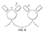
図9は、複数の印刷ヘッドステーション33が、それぞれ2個の印刷ヘッド32を備えており、その吐出部の軸が水平面を向いており、複数の印刷ヘッドステーション33が、互いに水平方向にオフセットされている装置を示す。保持デバイスは、実質的に半円形の経路を通り、物体31を印刷ヘッドステーションに運ぶ。
In FIG. 9, each of the plurality of
図示された実施形態において、印刷ヘッドステーションは、同じ高さであるが、他の実施形態において、印刷ヘッドステーションは、垂直方向にオフセットされ、かつ水平方向にオフセットされていてもよい。 In the illustrated embodiment, the print head stations are the same height, but in other embodiments, the print head stations may be offset in the vertical direction and offset in the horizontal direction.
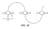
図10は、3個の印刷ヘッドステーション33が互いに水平方向にオフセットされており、複数の保持デバイスが、一連の実質的に半円形の経路で、連続する印刷ヘッドステーション33の近傍を通り、次いで、これらを通り得るように配置される装置を示す。それぞれの印刷ヘッドステーション33は、吐出部の軸が水平面を向いており、物体31が通り得る流路を形成するように互いに面するように配置された2個の印刷ヘッド32から作られる。上述の実施形態と同様に、一連の缶が、数個の保持デバイスを用い、一連の印刷ヘッドステーション33の近傍に順に向かってもよい。
FIG. 10 shows that three
代替的な実施形態において、4個より多いか、または4個より少ない印刷ヘッドステーション33が存在してもよく、それぞれの印刷ヘッドステーション33は、2個より多いか、または2個より少ない印刷ヘッド32を備えていてもよい。
In alternative embodiments, there may be more or less than four
別の実施形態において、経路は、半円形でなくてもよいが、その代わりに、垂直ではない接続部分によって接続された水平方向にずれて配置された垂直部分を含んでいてもよい。このような実施形態において、物体31は、経路の垂直部分の間、印刷ヘッドステーション33の近傍に向かい、印刷ヘッドステーション33を通ってもよい。
In another embodiment, the path may not be semi-circular, but instead may include horizontally offset vertical portions connected by non-vertical connecting portions. In such an embodiment, the
上述の任意の実施形態は、物体31の長手方向の軸に平行な方向にずれて配置された印刷ヘッド32を備えていてもよい。言い換えると、吐出部の軸に沿ってずれて配置された印刷ヘッド32または物体31の表面の運動に対して横断方向の印刷ヘッド32。このずれが小さい場合、すなわち、隣接する吐出部との間の空間が小さい場合、吐出部は、「交互に配置される(interleaved)」と言われ、さらに滑らかな高解像度の画像が得られる。図11のように、このずれが大きい場合、印刷ヘッド32は、「組み合わされる(stitched)」と言われ、もっと大きな幅を作成するために、吐出部アレイの有効な長さを広げる。
Any of the embodiments described above may include a
「組み合わされる」印刷ヘッドまたは「交互に配置される」印刷ヘッドは、物体31の反対側に配置されていてもよく、または同じ側に配置され、垂直方向にオフセットされ、重ね合わされてもよい。
“Combined” print heads or “interleaved” print heads may be located on opposite sides of the
図11は、4個の印刷ヘッド32を利用し、それぞれが1インチあたり150個の吐出部11を与える空間で複数の吐出部11(1センチメートルあたり60個の吐出部11)を有し(150dpi印刷)、使用時に適切な幅の印刷された画像を与える印刷バーまたはモジュール90を示し、それぞれの幅の印刷が隣接する印刷と組み合わされるように、印刷基材の移動方向(矢印91)に、多くの吐出部31(この場合は10)が印刷ヘッドの対の間で重なり合うように、それぞれの印刷ヘッド32と隣接する印刷ヘッド32が重なり合う。
FIG. 11 uses four
印刷ヘッド32は、物体の多くの回転を超えて、物体31の表面のもっと大きな面積をカバーするように、印刷する間、その吐出部アレイの軸(x軸、図1)に平行に移動してもよい。印刷ヘッド32は、物体31の表面のもっと大きな面積をカバーするように、印刷物の幅の間を断続的に、その吐出部アレイの軸(x軸、図1)に平行に移動してもよい。
The
Claims (41)
複数の印刷ヘッドと、
使用時に、物体を印刷ヘッドの間に移動させるように印刷ヘッドに対して移動可能な少なくとも1個の保持デバイスとを備え、
少なくとも1個の保持デバイスの経路は、互いに水平方向にオフセットする複数の垂直部分を有し、
それぞれの垂直部分は、互いに垂直方向にずれて配置され、片方がもう片方よりも直接的に上にくるように配置された少なくとも2個の同一の配置された印刷ヘッドを備え、
少なくとも1個の保持デバイスは、印刷ヘッドの間のその経路の一部または全てが垂直であるように、少なくとも2個の印刷ヘッドの間に物体を移動させる、円筒形の物体を印刷するための装置。 A device for printing cylindrical objects, the device comprising:
Multiple printheads;
At least one holding device movable relative to the print head to move an object between the print heads in use;
The path of the at least one holding device has a plurality of vertical portions offset horizontally from each other;
Each vertical portion comprises at least two identically arranged print heads arranged vertically offset from each other and arranged such that one is directly above the other,
At least one holding device for printing a cylindrical object that moves the object between at least two print heads such that part or all of its path between the print heads is vertical. apparatus.
少なくとも2個の印刷ヘッドステーションが、互いに水平方向にオフセットし、それぞれの印刷ヘッドステーションが、同じ高さにあり、互いに水平方向にずれて配置されるように配置された少なくとも2つの印刷ヘッドを備え、これによって、その間にギャップを生成し、このギャップを通って、印刷される円筒形の物体が通過し得るように配置された、複数の印刷ヘッドステーションと、
使用時に、印刷ヘッドの間の経路の一部または全てが垂直であるように、物体を印刷ヘッドの間に移動させるように印刷ヘッドに対して移動可能な少なくとも1個の保持デバイスとを備える、円筒形の物体を印刷するための装置。 A device for printing cylindrical objects, the device comprising:
At least two print head stations comprise at least two print heads arranged to be offset horizontally from each other, each print head station being at the same height and being offset from each other horizontally. A plurality of printhead stations arranged to create a gap therebetween, through which the cylindrical object to be printed can pass;
At least one holding device movable relative to the print head to move the object between the print heads so that in use, some or all of the path between the print heads is vertical. A device for printing cylindrical objects.
少なくとも1個の印刷ヘッドステーションに配置され、それぞれが吐出部の直線形のアレイを有する少なくとも2個の印刷ヘッドと、
少なくとも1個の印刷ヘッドが円筒形の物体を印刷することができるように、円筒形の物体を保持し、円筒形の物体を少なくとも1個の印刷ヘッドステーションの近傍に移動するためのものであり、印刷するとき、円筒形の物体の長手方向の軸が吐出部アレイと平行に維持されつつ、その長手方向の軸の周りを円筒形の物体が回転するように構成されている少なくとも1個の保持デバイスとを備える、円筒形の物体を印刷するための装置。 A device for printing cylindrical objects, the device comprising:
At least two printheads disposed in at least one printhead station, each having a linear array of ejection sections;
For holding a cylindrical object and moving the cylindrical object in the vicinity of at least one print head station so that at least one print head can print the cylindrical object. , When printing, at least one of the cylindrical objects configured to rotate about the longitudinal axis while the longitudinal axis of the cylindrical object is maintained parallel to the ejector array An apparatus for printing a cylindrical object comprising a holding device.
印刷される少なくとも1個の円筒形の物体が、印刷ヘッドまたは印刷ヘッドステーションの間の経路に沿って運ばれる、方法。 A method of printing using the apparatus according to any one of claims 1 to 39,
A method wherein at least one cylindrical object to be printed is carried along a path between print heads or print head stations.
次いで、保持デバイスが、円筒形の物体を、少なくとも1個の印刷ヘッドステーションまたは印刷ヘッドの近傍に運び、その場で印刷され、
次いで、保持デバイスが、円筒形の物体を第2の位置に運び、次いで、その場で、物体が取り出された後に、保持デバイスが第1の位置に戻る、請求項40に記載の方法。 First, when the holding device is in the first position, the cylindrical object is placed on at least one holding device;
The holding device then carries the cylindrical object to at least one print head station or the vicinity of the print head and is printed in place,
41. The method of claim 40, wherein the holding device then carries the cylindrical object to a second position and then returns to the first position after the object is removed in situ.
Applications Claiming Priority (3)
| Application Number | Priority Date | Filing Date | Title |
|---|---|---|---|
| GB1407440.5 | 2014-04-28 | ||
| GBGB1407440.5A GB201407440D0 (en) | 2014-04-28 | 2014-04-28 | Printing on cylindrical objects |
| PCT/GB2015/051229 WO2015166228A1 (en) | 2014-04-28 | 2015-04-28 | Printing on cylindrical objects |
Publications (2)
| Publication Number | Publication Date |
|---|---|
| JP2017515704A true JP2017515704A (en) | 2017-06-15 |
| JP2017515704A5 JP2017515704A5 (en) | 2018-05-31 |
Family
ID=50971982
Family Applications (1)
| Application Number | Title | Priority Date | Filing Date |
|---|---|---|---|
| JP2016564986A Pending JP2017515704A (en) | 2014-04-28 | 2015-04-28 | Printing on cylindrical objects |
Country Status (6)
| Country | Link |
|---|---|
| US (1) | US10011121B2 (en) |
| EP (1) | EP3137305B1 (en) |
| JP (1) | JP2017515704A (en) |
| CN (1) | CN106573477B (en) |
| GB (1) | GB201407440D0 (en) |
| WO (1) | WO2015166228A1 (en) |
Cited By (2)
| Publication number | Priority date | Publication date | Assignee | Title |
|---|---|---|---|---|
| JP2018012320A (en) * | 2016-07-08 | 2018-01-25 | 昭和アルミニウム缶株式会社 | Printer and can body manufacturing system |
| WO2020129779A1 (en) * | 2018-12-18 | 2020-06-25 | 昭和アルミニウム缶株式会社 | Print system |
Families Citing this family (8)
| Publication number | Priority date | Publication date | Assignee | Title |
|---|---|---|---|---|
| DE102015215227A1 (en) * | 2015-08-10 | 2017-02-16 | Krones Ag | Container treatment machine and method for printing on containers |
| US9827784B1 (en) * | 2016-05-25 | 2017-11-28 | Xerox Corporation | System for printing on three-dimensional (3D) objects |
| WO2018008315A1 (en) * | 2016-07-08 | 2018-01-11 | 昭和アルミニウム缶株式会社 | Printing apparatus and can body manufacturing system |
| US9789701B1 (en) * | 2016-09-19 | 2017-10-17 | Xerox Corporation | System and method for printing on a three-dimensional (3D) curved object |
| PT3535128T (en) * | 2016-11-02 | 2022-01-05 | Tonejet Ltd | Passive object handling device |
| WO2019060396A1 (en) | 2017-09-19 | 2019-03-28 | Ball Corporation | Container decoration apparatus and method |
| CN109465450A (en) * | 2018-11-21 | 2019-03-15 | 中船海洋动力部件有限公司 | Wire feed formula vertically prints the 3D printer of metal material |
| JP2022064494A (en) * | 2020-10-14 | 2022-04-26 | 昭和アルミニウム缶株式会社 | Printing system |
Citations (3)
| Publication number | Priority date | Publication date | Assignee | Title |
|---|---|---|---|---|
| WO2012131478A2 (en) * | 2011-03-31 | 2012-10-04 | Martinenghi S.R.L. | Device and method for printing cylindrical bodies |
| JP2012196909A (en) * | 2011-03-22 | 2012-10-18 | Seiko Epson Corp | Printing method |
| JP2012232771A (en) * | 2011-04-28 | 2012-11-29 | Toyo Seikan Kaisha Ltd | Inkjet printing device and printing method for seamless can using the same |
Family Cites Families (19)
| Publication number | Priority date | Publication date | Assignee | Title |
|---|---|---|---|---|
| CA2126235C (en) | 1991-12-18 | 2003-05-27 | Luis Lima-Marques | Method and apparatus for the production of discrete agglomerations of particulate matter |
| GB9601226D0 (en) | 1996-01-22 | 1996-03-20 | The Technology Partnership Plc | Ejection apparatus and method |
| RU2142367C1 (en) | 1996-01-22 | 1999-12-10 | Таунджет Корпорейшн ПТИ, Лтд | Ejector for application of material from liquid |
| GB9701318D0 (en) | 1997-01-22 | 1997-03-12 | Tonejet Corp Pty Ltd | Ejection apparatus |
| GB9706069D0 (en) | 1997-03-24 | 1997-05-14 | Tonejet Corp Pty Ltd | Application of differential voltage to a printhead |
| EP1095772A1 (en) * | 1999-10-25 | 2001-05-02 | Tonejet Corporation Pty Ltd | Printhead |
| DE60206142T2 (en) | 2002-05-31 | 2006-01-19 | Tonejet Ltd., Royston | printhead |
| DE10226500B4 (en) * | 2002-06-14 | 2010-04-22 | Ball Packaging Europe Holding Gmbh & Co. Kg | Device for surface treatment of parts |
| US6769357B1 (en) | 2003-06-05 | 2004-08-03 | Sequa Can Machinery, Inc. | Digital can decorating apparatus |
| DE102006001223A1 (en) | 2006-01-10 | 2007-07-12 | Khs Ag | Apparatus for printing on bottles or similar containers |
| ITBO20060726A1 (en) * | 2006-10-23 | 2007-01-22 | Gd Spa | PACKAGE PRINTING UNIT. |
| JP5040506B2 (en) * | 2007-07-31 | 2012-10-03 | ブラザー工業株式会社 | Inkjet recording device |
| JP5018347B2 (en) * | 2007-08-30 | 2012-09-05 | ブラザー工業株式会社 | Inkjet recording device |
| DE102009013477B4 (en) | 2009-03-19 | 2012-01-12 | Khs Gmbh | Printing device for printing on bottles or similar containers |
| ES2803244T3 (en) * | 2009-09-15 | 2021-01-25 | Tonejet Ltd | Inkjet Liquid Ink and Printing Procedure |
| DE102010034780A1 (en) * | 2010-08-18 | 2012-02-23 | Volker Till | Apparatus and method for printing on containers |
| EP2471657A1 (en) * | 2010-12-30 | 2012-07-04 | Tonejet Limited | Ink manifold for an inkjet print head |
| DE102011007979A1 (en) | 2011-01-05 | 2012-07-05 | Till Gmbh | Machine for printing on containers |
| US9610781B2 (en) | 2011-04-25 | 2017-04-04 | Show A Aluminum Can Corporation | Image forming device and method for manufacturing can body on which image is formed |
-
2014
- 2014-04-28 GB GBGB1407440.5A patent/GB201407440D0/en not_active Ceased
-
2015
- 2015-04-28 US US15/307,076 patent/US10011121B2/en active Active
- 2015-04-28 EP EP15719285.7A patent/EP3137305B1/en active Active
- 2015-04-28 CN CN201580022817.1A patent/CN106573477B/en not_active Expired - Fee Related
- 2015-04-28 JP JP2016564986A patent/JP2017515704A/en active Pending
- 2015-04-28 WO PCT/GB2015/051229 patent/WO2015166228A1/en active Application Filing
Patent Citations (4)
| Publication number | Priority date | Publication date | Assignee | Title |
|---|---|---|---|---|
| JP2012196909A (en) * | 2011-03-22 | 2012-10-18 | Seiko Epson Corp | Printing method |
| WO2012131478A2 (en) * | 2011-03-31 | 2012-10-04 | Martinenghi S.R.L. | Device and method for printing cylindrical bodies |
| JP2012232771A (en) * | 2011-04-28 | 2012-11-29 | Toyo Seikan Kaisha Ltd | Inkjet printing device and printing method for seamless can using the same |
| US20140028771A1 (en) * | 2011-04-28 | 2014-01-30 | Toyo Seikan Group Holdings, Ltd. | Ink-jet printing apparatus and method of printing seamless cans by using the same printing apparatus |
Cited By (5)
| Publication number | Priority date | Publication date | Assignee | Title |
|---|---|---|---|---|
| JP2018012320A (en) * | 2016-07-08 | 2018-01-25 | 昭和アルミニウム缶株式会社 | Printer and can body manufacturing system |
| WO2020129779A1 (en) * | 2018-12-18 | 2020-06-25 | 昭和アルミニウム缶株式会社 | Print system |
| JP2020097440A (en) * | 2018-12-18 | 2020-06-25 | 昭和アルミニウム缶株式会社 | Printing system |
| JP7240165B2 (en) | 2018-12-18 | 2023-03-15 | アルテミラ株式会社 | printing system |
| US11660878B2 (en) | 2018-12-18 | 2023-05-30 | Altemira Co., Ltd. | Print system |
Also Published As
| Publication number | Publication date |
|---|---|
| EP3137305A1 (en) | 2017-03-08 |
| WO2015166228A1 (en) | 2015-11-05 |
| US10011121B2 (en) | 2018-07-03 |
| CN106573477A (en) | 2017-04-19 |
| GB201407440D0 (en) | 2014-06-11 |
| US20170050446A1 (en) | 2017-02-23 |
| EP3137305B1 (en) | 2020-12-23 |
| CN106573477B (en) | 2019-08-27 |
Similar Documents
| Publication | Publication Date | Title |
|---|---|---|
| JP2017515704A (en) | Printing on cylindrical objects | |
| JP7016208B2 (en) | Liquid discharge head, liquid discharge unit, liquid discharge device | |
| JP5264000B2 (en) | Nozzle layout for fluid droplet discharge | |
| EP2678162B1 (en) | Printing system and related method | |
| JP6517234B2 (en) | Tablet printing apparatus and tablet printing method | |
| JP2003191474A (en) | Unit and method for controlling ink droplets, and integrated ink-jet printing head | |
| JP4872953B2 (en) | Droplet discharge head and droplet discharge apparatus | |
| JP2016159514A (en) | Liquid discharge device and foreign matter discharge method for liquid discharge head | |
| EP3351388B1 (en) | Ink jet head and ink jet recording apparatus | |
| JP2017065249A (en) | Liquid discharge head, liquid discharge unit, and liquid discharge device | |
| JP2018154085A (en) | Liquid discharge head, liquid discharge unit, and device for discharging liquid | |
| JP2016068290A (en) | Inkjet printing device and method for the same | |
| JP2022060431A (en) | Liquid discharge head and liquid discharge device | |
| EP3476607A1 (en) | Fluid ejection head and fluid ejection apparatus | |
| JP2019130872A (en) | Liquid ejection head, liquid ejection unit, and device ejecting liquid | |
| EP3476606A1 (en) | Fluid ejection head and fluid ejection apparatus | |
| JP6064650B2 (en) | Droplet discharge device | |
| JP5936512B2 (en) | Liquid discharge head and image recording apparatus | |
| JP2009269257A (en) | Liquid discharge apparatus | |
| JP6362182B2 (en) | Industrial inkjet drawing equipment | |
| JP2015182237A (en) | Ink jet recording method | |
| JP2019209595A (en) | Liquid discharge head, liquid discharge unit, and liquid discharge device | |
| JP2017024409A (en) | Droplet discharging device and droplet discharging method | |
| JP2006240024A (en) | Liquid droplet discharging head and liquid droplet discharging apparatus | |
| JP6711113B2 (en) | Liquid preheating device, liquid discharge unit, and device for discharging liquid |
Legal Events
| Date | Code | Title | Description |
|---|---|---|---|
| A521 | Request for written amendment filed |
Free format text: JAPANESE INTERMEDIATE CODE: A523 Effective date: 20180416 |
|
| A621 | Written request for application examination |
Free format text: JAPANESE INTERMEDIATE CODE: A621 Effective date: 20180416 |
|
| A977 | Report on retrieval |
Free format text: JAPANESE INTERMEDIATE CODE: A971007 Effective date: 20190315 |
|
| A131 | Notification of reasons for refusal |
Free format text: JAPANESE INTERMEDIATE CODE: A131 Effective date: 20190402 |
|
| A601 | Written request for extension of time |
Free format text: JAPANESE INTERMEDIATE CODE: A601 Effective date: 20190617 |
|
| A521 | Request for written amendment filed |
Free format text: JAPANESE INTERMEDIATE CODE: A523 Effective date: 20190820 |
|
| A02 | Decision of refusal |
Free format text: JAPANESE INTERMEDIATE CODE: A02 Effective date: 20200107 |