JP6362182B2 - Industrial inkjet drawing equipment - Google Patents
Industrial inkjet drawing equipment Download PDFInfo
- Publication number
- JP6362182B2 JP6362182B2 JP2016134728A JP2016134728A JP6362182B2 JP 6362182 B2 JP6362182 B2 JP 6362182B2 JP 2016134728 A JP2016134728 A JP 2016134728A JP 2016134728 A JP2016134728 A JP 2016134728A JP 6362182 B2 JP6362182 B2 JP 6362182B2
- Authority
- JP
- Japan
- Prior art keywords
- nozzle
- ink jet
- ink
- inkjet head
- head
- Prior art date
- Legal status (The legal status is an assumption and is not a legal conclusion. Google has not performed a legal analysis and makes no representation as to the accuracy of the status listed.)
- Active
Links
Images


Description
本発明は、複数ノズルを有するインクジェットヘッドを例えば水平方向に対してノズル面が垂直となるよう90度縦向きにして配置し使用する場合など、インクジェットヘッドを回転させてノズル面の角度を変更して印刷する場合において、ノズル内のインクを押し出してその後ふき取る動作、いわゆるノズル面のクリーニング動作時とノズルからインクを吐出させる印刷時における、ノズル内を一定の圧力に保つための方法および手段を備えたインクジェット描画装置に関する。 The present invention changes the angle of the nozzle surface by rotating the inkjet head, such as when an inkjet head having a plurality of nozzles is used with the nozzle surface being vertically oriented 90 degrees so that the nozzle surface is perpendicular to the horizontal direction. in case of printing Te, then wipe operation extruding the ink in the nozzle, at the time of printing to eject ink from the cleaning operation and the nozzles of the so-called nozzle surface comprises a method and means for maintaining the nozzle at a constant pressure The present invention relates to an inkjet drawing apparatus .
複数ノズルを有するインクジェットヘッドは、ノズル面が基材の印刷面に対向して平行となるよう配置され、インクジェットヘッドを水平方向に移動させて印刷を行うか、ノズル面が基材の印刷面に対向して平行となるようインクジェットヘッドを固定させ、印刷基材を移動させて印刷を行う方法が一般的である。 An inkjet head having a plurality of nozzles is arranged so that the nozzle surface is parallel to the printing surface of the substrate, and printing is performed by moving the inkjet head in the horizontal direction, or the nozzle surface is on the printing surface of the substrate. In general, the inkjet head is fixed so as to face each other in parallel and the printing substrate is moved to perform printing.
特許第4710686号Japanese Patent No. 4710686
近年インクジェット技術をいろいろな分野の加飾や描画用途に応用する事例が多くみられる。いわゆる産業用インクジェットという分野である。近年ではエレクトロニクス、バイオロジー分野、建材、捺染用途などに広く展開され、一部は実用化されている。産業用インクジェット技術の利点は必要とされる場所に必要な量だけ塗布出来ることである。このため従来プロセスと比較すると材料の無駄が少なく、工程短縮などのメリットがある。 In recent years, there are many cases where inkjet technology is applied to decoration and drawing applications in various fields. This is the field of so-called industrial inkjet. In recent years, it has been widely deployed in the fields of electronics, biology, building materials, textile printing, and some have been put into practical use. The advantage of industrial inkjet technology is that it can be applied in the required amount where it is needed. For this reason, compared to the conventional process, there is less material waste and there are advantages such as process shortening.
例えば建材など大判基材の側面を印刷する場合、垂直方向に基材を立てて大判基材の側面を水平の状態に配置して印刷することは難しい。そこで、インクジェットノズルから吐出されるインクの方向が水平方向となるよう、インクジェットヘッドのノズル面をノズル列方向に90度回転させるなどの方法を用いて、インクジェットヘッドを回転させることで、インクジェットヘッドのノズル面を、インクジェットヘッドのノズル面が印刷基材の印刷面に対向して略平行となるよう調整して印刷する必要があるが、2a.のノズル面のクリーニング動作を印刷時のそのままの角度で実施すると、図1の3.の垂れたインクの回り込みの様にノズルから垂れたインクがインクジェットヘッドのノズル面以外のところに回り込み、インクジェットヘッドの周辺部品にインクが付着して部品が劣化したり破損したりという問題があることから、インクジェットヘッドのノズル面を一たん水平方向にしてからノズル面のクリーニング動作を行う必要がある。 For example, when printing the side surface of a large-sized base material such as a building material, it is difficult to print by placing the base material in the vertical direction and arranging the side surface of the large-sized base material in a horizontal state . Therefore, as the direction of ink ejected from the inkjet nozzle becomes horizontal, the nozzle surface of the inkjet head using the method, etc. $ WARNING Do not rotated 90 degrees in the nozzle row direction, by rotating the ink jet head, an ink jet head of the nozzle surface, although the nozzle surface of the inkjet head needs to be printed is adjusted so as to be substantially parallel to face the printing surface of the printing substrate, 2 a. When the nozzle surface cleaning operation is performed at the same angle at the time of printing as shown in FIG. The ink dripping from the nozzle, like the sneaking of the dripping ink, wraps around the area other than the nozzle surface of the ink jet head and the ink adheres to the peripheral parts of the ink jet head, causing the parts to deteriorate or break. Therefore, it is necessary to perform the cleaning operation of the nozzle surface after the nozzle surface of the ink jet head is made horizontal once.
この場合、クリーニング時とインクジェットヘッドの角度を変えた印刷時において、インクを一時的にためておくサブタンク内のインク液面とノズル面の高さが変わることにより、ノズル内の圧力が一定にならず、安定した印刷が困難となる問題があった。また、例えば、インクジェットヘッドのノズル面をノズル列方向に90度回転させるなど、インクジェットヘッドの角度を変えた印刷を行う際に、インクジェットヘッドのノズル面の総ノズル幅が広い場合、ノズル面におけるノズル列の先頭と後端で高さに差が生じるため、ノズル内の圧力に差が生じる。その差が大きくなると安定した吐出が困難になるという問題があった。 In this case, the pressure in the nozzle is kept constant by changing the height of the ink liquid surface and the nozzle surface in the sub-tank where ink is temporarily stored during cleaning and printing with the ink jet head angle changed. Therefore, there has been a problem that stable printing becomes difficult. In addition, for example, when the nozzle face of the inkjet head is wide when performing printing at different angles of the inkjet head, such as rotating the nozzle face of the inkjet head 90 degrees in the nozzle row direction, the nozzles on the nozzle face Since there is a difference in height between the head and the rear end of the row, there is a difference in the pressure in the nozzle. When the difference increases, there is a problem that stable ejection becomes difficult.
本発明は、上記従来技術の問題点を解決し、インクジェットヘッドのノズルから吐出されるインクの方向が略水平方向となるようインクジェットヘッドのノズル面をノズル列方向に約90度回転させて印刷する場合など、インクジェットヘッドを回転させてインクジェットヘッドの角度を変えて印刷する場合に、印刷時とクリーニング時とでインクジェットヘッドの向きを回転させたとしても、インクジェットヘッド内の圧力を一定に保ち、安定した印刷を行うことのできるインクジェット描画装置を提供することを課題とする。The present invention solves the above-mentioned problems of the prior art, and prints by rotating the nozzle surface of the inkjet head about 90 degrees in the nozzle row direction so that the direction of ink ejected from the nozzle of the inkjet head is substantially horizontal. When printing by changing the angle of the inkjet head by rotating the inkjet head, even if the orientation of the inkjet head is rotated during printing and cleaning, the pressure inside the inkjet head is kept constant and stable. It is an object of the present invention to provide an ink jet drawing apparatus that can perform printing.
上記の問題点を解決するために下記のような手段を提案する。
(1)印刷時とノズル面クリーニング時とでインクジェットヘッドの角度を調整することにより吐出方向の角度を変える回転機構を備える。
(2)回転機構の回転中心を、インクジェットヘッドのノズル面から吐出方向と反対方向に35mm以下にし、且つノズル面のノズル列方向のノズル列幅における略中心とする。
(3)ノズル面クリーニング時は、ノズル面がクリーニングユニットのインク受け面に対向して略水平になるようにし、印刷時は角度を変えても、インク供給のためのサブタンクの液面とインクジェットヘッドの回転中心の高さが一定となるようにし、尚且つその際のサブタンク内の圧力が一定となるように制御を行う。
(4)インクジェットヘッドの角度を変えて印刷する際の印刷に使用するノズル面のノズル列の先頭位置と使用ノズル領域を変更し、個々のノズル内の圧力が安定して吐出が可能な範囲を使用ノズル領域とする。
In order to solve the above problems, the following means are proposed.
(1) A rotation mechanism is provided that changes the angle of the ejection direction by adjusting the angle of the inkjet head during printing and during nozzle surface cleaning.
(2) The rotation center of the rotation mechanism is set to 35 mm or less from the nozzle surface of the inkjet head in the direction opposite to the ejection direction, and is substantially the center in the nozzle row width of the nozzle surface in the nozzle row direction.
(3) At the time of nozzle surface cleaning, the nozzle surface is substantially horizontal facing the ink receiving surface of the cleaning unit, and at the time of printing, even if the angle is changed, the liquid level of the sub tank for supplying ink and the inkjet head Control is performed so that the height of the rotation center of the sub-tank is constant and the pressure in the sub-tank at that time is constant.
(4) Changing the head position of the nozzle array on the nozzle surface used for printing when changing the angle of the ink-jet head and the used nozzle area, the range in which the pressure in each nozzle can be stably ejected is changed. Use nozzle area.
本発明では、クリーニング動作の実施後に印刷動作を行うインクジェット描画装置の一連の流れにおいて、印刷時のインクジェットヘッドをノズル列方向に90度回転させ、ノズルからのインク吐出方向を水平方向にして印刷するなど、インクジェットヘッドを回転させてインクジェットヘッドの角度を変えて印刷しても、安定した吐出が可能な産業用インクジェット描画装置が出来た。また、クリーニング時に垂れたインクがインクジェットヘッド側面に回り込む問題も回避出来た。 In the present invention, in a series of flows of an ink jet drawing apparatus that performs a printing operation after performing a cleaning operation, the ink jet head at the time of printing is rotated 90 degrees in the nozzle row direction , and printing is performed with the ink ejection direction from the nozzles being horizontal. Thus, an industrial ink jet drawing apparatus capable of stable ejection even when the ink jet head is rotated and the angle of the ink jet head is changed is printed . Moreover, the problem that the ink dripping at the time of cleaning wraps around the side surface of the inkjet head can be avoided.
図7は、本発明の実施例で1a.のインクジェットヘッドのノズル面をノズル列方向に対して90度回転させた状態を側面から見た構成図で、42.の基材の43.の基材の印刷面に印刷を行い、47.の回転機構でノズル面が水平方向となるよう回転させた後、41.のクリーニングユニットでノズル面をクリーニングするための全体構成を示したものである。 FIG. 7 shows an embodiment of the present invention with 1a. 42 is a configuration diagram of the state in which the nozzle surface of the inkjet head of FIG. 43 of the base material. Printing on the printing surface of the substrate of 47. 47. After rotating the nozzle surface in the horizontal direction with the rotation mechanism of No. 41, 41. 2 shows an overall configuration for cleaning the nozzle surface with the cleaning unit.
図8は、本発明の実施例で1a.のインクジェットヘッドのノズル面をノズル列方向に対して90度回転させた状態を上面から見た構成図で、40.のインクジェットヘッドが搭載されたキャリッジ部を44.のX軸の搭載し、34.の様にインクジェットヘッドが搭載されたキャリッジ部を左右に移動させて、42.の基材の43.の基材の印刷面に印刷するインクジェット描画装置の全体構成を示すものである。 FIG. 8 shows an embodiment of the present invention with 1a. FIG. 40 is a configuration diagram in which the nozzle surface of the inkjet head of FIG. 44. The carriage unit on which the inkjet head is mounted is mounted at 44. Of X axis, 34. 42. Move the carriage portion on which the inkjet head is mounted to the left and right as shown in FIG. 43 of the base material. 1 shows the overall configuration of an ink jet drawing apparatus that prints on the printing surface of a base material.
図9は、本発明の実施例で1a.のインクジェットヘッドのノズル面をノズル列方向に対して90度回転させた状態を上面から見た構成図で、40.のインクジェットヘッドが搭載されたキャリッジ部は移動せずに、42.の基材が46.の基材搬送部により移動し、43.の基材の印刷面に印刷するインクジェット描画装置の全体構成を示すものである。 FIG. 9 shows an embodiment of the present invention with 1a. FIG. 40 is a configuration diagram in which the nozzle surface of the inkjet head of FIG. The carriage portion on which the inkjet head is mounted does not move, and 42. The base material is 46. The base material transport unit moves the 1 shows the overall configuration of an ink jet drawing apparatus that prints on the printing surface of a base material.
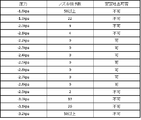
図2は、インクジェットヘッドのノズル面が水平となるよう配置した場合の、インクジェットヘッドにインクを供給するために一たんインクをためておくサブタンク内の圧力とノズル抜け数と安定吐出が可能な範囲の例を示したものである。 FIG. 2 shows the pressure, the number of missing nozzles, and the range in which stable ejection is possible when the ink is supplied to the inkjet head when the nozzle surface of the inkjet head is horizontal. This is an example.
図3は、図2測定時のサブタンク液面とインクジェットヘッドのノズル面の高さ関係を示したものである。1a.のインクジェットヘッドに10.のサブタンクから11.のインクチューブを通して12.のインクを供給し、10.のサブタンクは、13.の圧力制御部によって、一定の圧力を維持している。その際の2a.のノズル面は水平に配置し、12.のサブタンク内のインクの液面と、2a.のノズル面との高さの差は200mmとした。
FIG. 3 shows the height relationship between the sub-tank liquid surface and the nozzle surface of the inkjet head during the measurement of FIG. 1a. 10. Ink
図2の安定吐出が可能な範囲は、サブタンク液面との差が200mmであった場合、マイナス2.2kpaからマイナス2.8kpaであることがわかる。その範囲の幅は、0.6kpaで、水頭差に変換すると約61.2mmH2Oである。このことから、インクジェットヘッドをノズル列方向に回転させた場合でも、先頭ノズルから後端ノズルまでの長さと、印刷時及び、クリーニング時においても高さの差を61.2mm以内とすることで安定的な吐出が可能である。この安定的に吐出が可能な範囲は、インクジェットヘッドやインクにより異なるため、インクジェットヘッドやインクが変わった場合は、その都度測定が必要である。 The range in which stable discharge is possible in FIG. 2 is found to be from minus 2.2 kpa to minus 2.8 kpa when the difference from the sub tank liquid level is 200 mm. The width of the range is 0.6 kpa, which is about 61.2 mmH2O when converted to a hydraulic head difference. Therefore, even when the inkjet head is rotated in the nozzle row direction, the difference between the length from the first nozzle to the rear nozzle and the height during printing and cleaning is stable within 61.2 mm. Discharge is possible. The range in which stable ejection can be performed varies depending on the inkjet head and ink, and therefore measurement is required each time the inkjet head or ink changes.
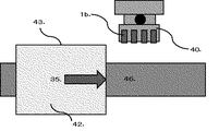
図4は、インクジェットヘッドを回転させた場合のノズル面から回転中心までの距離と、ノズル列方向の先頭ノズルから後尾ノズルまでの位置関係を表したものである。
例えば、1a.のインクジェットヘッドを1b.の90度回転の様にノズル列方向に回転させた場合、31.の回転中心と2a.のノズル面までの距離を35mm以下とし、21.のノズル先端から23.のノズル後尾の略中心とする事で、回転後の21a.の先頭ノズルから2a.のノズル面までの距離をできるだけ離すことなく回転が可能であり、21a.の様に先頭ノズル位置を変更し、22.の使用ノズル長を例えば50mmとすることで、2a.のノズル面に対して1a.のインクジェットヘッドを90度回転させたとしても、先頭ノズルの先端と水平方向の時のノズル面との距離の差は、32.の水平状態でのノズル面からと変更後のノズル先端との差が示すように60mmとなり、上記で示した、水頭差61.2mm以内にすることが可能である。
FIG. 4 shows the distance from the nozzle surface to the center of rotation when the inkjet head is rotated and the positional relationship from the first nozzle to the rear nozzle in the nozzle row direction.
For example, 1a. 1b. When rotated in the nozzle row direction as in the case of 90 ° rotation, 31. Of rotation and 2a. 21. The distance to the nozzle surface is 35 mm or less. 23. from the nozzle tip. 21a. 2a. Can be rotated with as little distance to the nozzle surface as possible, 21a. Change the top nozzle position as shown in FIG. By using a nozzle length of 50 mm, for example, 2a. 1a. Even if the inkjet head is rotated 90 degrees, the difference in distance between the tip of the top nozzle and the nozzle surface in the horizontal direction is 32. As shown in the difference between the nozzle surface in the horizontal state and the nozzle tip after the change, the difference is 60 mm, and the above-mentioned water head difference can be within 61.2 mm.
図5はインクジェットヘッドと47.の回転機構、10.のサブタンクの構成図で、図6の1a.のインクジェットヘッドの角度が変わっても、サブタンクは、回転機構とは別の場所に固定されており回転中心とサブタンクの液面との位置関係は、一定である。 FIG. 10. Rotation mechanism of The sub-tank of FIG. Even if the angle of the inkjet head changes, the sub tank is fixed at a location different from the rotation mechanism, and the positional relationship between the rotation center and the liquid level of the sub tank is constant.
1a.インクジェットヘッド
1b.90度ノズル列方向に回転されたインクジェットヘッド
2a.ノズル面
2b.点線部の拡大
3.垂れたインクの回り込み
10.サブタンク
11.インクチューブ
12.インク
13.圧力制御部
21.先頭ノズル位置
21a.使用ノズル領域を限定した場合の先頭ノズル位置
22.使用ノズル領域
23.後尾ノズル
23a.使用ノズル領域を限定した場合の後尾ノズル位置
30.使用ノズル領域の略中心から回転中心までの距離
31.回転中心
32.水平状態における先頭ノズル位置と回転後の先頭ノズル位置の高さの差
33.回転方向
34.キャリッジ移動方向(左右)
35.基材搬送方向
40.キャリッジ
41.クリーニングユニット
42.印刷基材
43.基材の印刷面
44.X軸
45.Z軸
46.基材搬送部
47.回転機構
1a.
2a. Nozzle surface 2b. 2. Enlarged dotted
35.
Claims (3)
The pressure in the sub tank for temporarily storing ink to supply ink to the inkjet head is controlled at a constant pressure, and the height between the sub tank and the rotation center of the inkjet head is constant. The inkjet drawing apparatus according to claim 1, wherein
Priority Applications (1)
| Application Number | Priority Date | Filing Date | Title |
|---|---|---|---|
| JP2016134728A JP6362182B2 (en) | 2016-07-07 | 2016-07-07 | Industrial inkjet drawing equipment |
Applications Claiming Priority (1)
| Application Number | Priority Date | Filing Date | Title |
|---|---|---|---|
| JP2016134728A JP6362182B2 (en) | 2016-07-07 | 2016-07-07 | Industrial inkjet drawing equipment |
Publications (3)
| Publication Number | Publication Date |
|---|---|
| JP2018001687A JP2018001687A (en) | 2018-01-11 |
| JP2018001687A5 JP2018001687A5 (en) | 2018-05-17 |
| JP6362182B2 true JP6362182B2 (en) | 2018-07-25 |
Family
ID=60947105
Family Applications (1)
| Application Number | Title | Priority Date | Filing Date |
|---|---|---|---|
| JP2016134728A Active JP6362182B2 (en) | 2016-07-07 | 2016-07-07 | Industrial inkjet drawing equipment |
Country Status (1)
| Country | Link |
|---|---|
| JP (1) | JP6362182B2 (en) |
Families Citing this family (1)
| Publication number | Priority date | Publication date | Assignee | Title |
|---|---|---|---|---|
| US20230356530A1 (en) | 2022-03-28 | 2023-11-09 | Riso Kagaku Corporation | Inkjet printer, flow path resistance adjustment method, and printing method |
Family Cites Families (6)
| Publication number | Priority date | Publication date | Assignee | Title |
|---|---|---|---|---|
| JPH05177827A (en) * | 1991-10-29 | 1993-07-20 | Tokyo Electric Co Ltd | Ink-jet printer |
| JPH10235885A (en) * | 1997-02-24 | 1998-09-08 | Konica Corp | Ink jet printer |
| JP3789300B2 (en) * | 2000-12-12 | 2006-06-21 | シャープ株式会社 | Inkjet printer |
| JP2011235507A (en) * | 2010-05-10 | 2011-11-24 | Konica Minolta Holdings Inc | Liquid droplet discharging device |
| ES2702701T3 (en) * | 2010-12-30 | 2019-03-05 | Alltec Angewandte Laserlicht Tech Gesellschaft Mit Beschraenkter Haftung | Marking apparatus |
| JP6119261B2 (en) * | 2013-01-18 | 2017-04-26 | 株式会社リコー | Image forming apparatus |
-
2016
- 2016-07-07 JP JP2016134728A patent/JP6362182B2/en active Active
Also Published As
| Publication number | Publication date |
|---|---|
| JP2018001687A (en) | 2018-01-11 |
Similar Documents
| Publication | Publication Date | Title |
|---|---|---|
| US7819055B2 (en) | Three-dimensional printer | |
| US8104856B2 (en) | Printer | |
| US20080218542A1 (en) | Printer and printing method | |
| JP5366404B2 (en) | Printhead and system using printhead | |
| JP2017515704A (en) | Printing on cylindrical objects | |
| JP5187153B2 (en) | Recording apparatus and recording method in the recording apparatus | |
| JP6362182B2 (en) | Industrial inkjet drawing equipment | |
| JP2018001687A5 (en) | ||
| JP5251351B2 (en) | Liquid ejector | |
| EP3595866B1 (en) | Method of calibrating an inkjet based three dimensional printing system | |
| JP2012081658A (en) | Liquid ejecting apparatus and liquid ejecting method | |
| JP5987276B2 (en) | Image recording device | |
| US20200070522A1 (en) | Liquid Dispensers | |
| JP2009006685A (en) | Fluid ejector and fluid ejection method | |
| JP2008221183A (en) | Liquid droplet ejection/coating apparatus and method for preparing coated article | |
| JP2014188816A (en) | Recording apparatus | |
| JP2007260501A (en) | Method and apparatus for coating construction plate | |
| JP2010131562A (en) | Apparatus for jet-coating with liquid droplets and method of producing coated body | |
| JP2012148213A (en) | Method and apparatus for inkjet coating | |
| JP5915234B2 (en) | Droplet discharge device | |
| JP5617325B2 (en) | Fluid ejection device | |
| JP2017128078A (en) | Droplet discharge device | |
| CN111376589A (en) | Ink jet printing apparatus and cleaning method thereof | |
| JP2011098555A (en) | Liquid ejection device | |
| JP2012116063A (en) | Inkjet recording device and method for preventing dew condensation of inkjet head |
Legal Events
| Date | Code | Title | Description |
|---|---|---|---|
| A521 | Written amendment |
Free format text: JAPANESE INTERMEDIATE CODE: A523 Effective date: 20180326 |
|
| A621 | Written request for application examination |
Free format text: JAPANESE INTERMEDIATE CODE: A621 Effective date: 20180326 |
|
| A871 | Explanation of circumstances concerning accelerated examination |
Free format text: JAPANESE INTERMEDIATE CODE: A871 Effective date: 20180326 |
|
| A975 | Report on accelerated examination |
Free format text: JAPANESE INTERMEDIATE CODE: A971005 Effective date: 20180412 |
|
| A131 | Notification of reasons for refusal |
Free format text: JAPANESE INTERMEDIATE CODE: A131 Effective date: 20180418 |
|
| A521 | Written amendment |
Free format text: JAPANESE INTERMEDIATE CODE: A523 Effective date: 20180501 |
|
| TRDD | Decision of grant or rejection written | ||
| A01 | Written decision to grant a patent or to grant a registration (utility model) |
Free format text: JAPANESE INTERMEDIATE CODE: A01 Effective date: 20180621 |
|
| A61 | First payment of annual fees (during grant procedure) |
Free format text: JAPANESE INTERMEDIATE CODE: A61 Effective date: 20180621 |
|
| R150 | Certificate of patent or registration of utility model |
Ref document number: 6362182 Country of ref document: JP Free format text: JAPANESE INTERMEDIATE CODE: R150 |
|
| R250 | Receipt of annual fees |
Free format text: JAPANESE INTERMEDIATE CODE: R250 |