JP2017501067A - Vehicle battery precharge function - Google Patents
Vehicle battery precharge function Download PDFInfo
- Publication number
- JP2017501067A JP2017501067A JP2016527399A JP2016527399A JP2017501067A JP 2017501067 A JP2017501067 A JP 2017501067A JP 2016527399 A JP2016527399 A JP 2016527399A JP 2016527399 A JP2016527399 A JP 2016527399A JP 2017501067 A JP2017501067 A JP 2017501067A
- Authority
- JP
- Japan
- Prior art keywords
- state
- charge
- battery
- hybrid vehicle
- engine
- Prior art date
- Legal status (The legal status is an assumption and is not a legal conclusion. Google has not performed a legal analysis and makes no representation as to the accuracy of the status listed.)
- Withdrawn
Links
- 238000000034 method Methods 0.000 claims abstract description 20
- 230000005540 biological transmission Effects 0.000 description 14
- 230000006870 function Effects 0.000 description 7
- 238000002485 combustion reaction Methods 0.000 description 6
- 239000000446 fuel Substances 0.000 description 4
- CURLTUGMZLYLDI-UHFFFAOYSA-N Carbon dioxide Chemical compound O=C=O CURLTUGMZLYLDI-UHFFFAOYSA-N 0.000 description 2
- LFQSCWFLJHTTHZ-UHFFFAOYSA-N Ethanol Chemical compound CCO LFQSCWFLJHTTHZ-UHFFFAOYSA-N 0.000 description 2
- 230000001133 acceleration Effects 0.000 description 1
- 230000009471 action Effects 0.000 description 1
- 230000003213 activating effect Effects 0.000 description 1
- 230000002411 adverse Effects 0.000 description 1
- 238000013459 approach Methods 0.000 description 1
- 239000002551 biofuel Substances 0.000 description 1
- 239000006227 byproduct Substances 0.000 description 1
- 229910002092 carbon dioxide Inorganic materials 0.000 description 1
- 239000001569 carbon dioxide Substances 0.000 description 1
- 230000008859 change Effects 0.000 description 1
- 230000007423 decrease Effects 0.000 description 1
- 230000007613 environmental effect Effects 0.000 description 1
- 230000005484 gravity Effects 0.000 description 1
- 230000003862 health status Effects 0.000 description 1
- 238000001566 impedance spectroscopy Methods 0.000 description 1
- 238000004519 manufacturing process Methods 0.000 description 1
- 230000007246 mechanism Effects 0.000 description 1
- 230000001172 regenerating effect Effects 0.000 description 1
- 230000008929 regeneration Effects 0.000 description 1
- 238000011069 regeneration method Methods 0.000 description 1
- 231100000331 toxic Toxicity 0.000 description 1
- 230000002588 toxic effect Effects 0.000 description 1
Images

Classifications
-
- B—PERFORMING OPERATIONS; TRANSPORTING
- B60—VEHICLES IN GENERAL
- B60W—CONJOINT CONTROL OF VEHICLE SUB-UNITS OF DIFFERENT TYPE OR DIFFERENT FUNCTION; CONTROL SYSTEMS SPECIALLY ADAPTED FOR HYBRID VEHICLES; ROAD VEHICLE DRIVE CONTROL SYSTEMS FOR PURPOSES NOT RELATED TO THE CONTROL OF A PARTICULAR SUB-UNIT
- B60W10/00—Conjoint control of vehicle sub-units of different type or different function
- B60W10/24—Conjoint control of vehicle sub-units of different type or different function including control of energy storage means
- B60W10/26—Conjoint control of vehicle sub-units of different type or different function including control of energy storage means for electrical energy, e.g. batteries or capacitors
-
- B60K35/28—
-
- B60K35/60—
-
- B—PERFORMING OPERATIONS; TRANSPORTING
- B60—VEHICLES IN GENERAL
- B60K—ARRANGEMENT OR MOUNTING OF PROPULSION UNITS OR OF TRANSMISSIONS IN VEHICLES; ARRANGEMENT OR MOUNTING OF PLURAL DIVERSE PRIME-MOVERS IN VEHICLES; AUXILIARY DRIVES FOR VEHICLES; INSTRUMENTATION OR DASHBOARDS FOR VEHICLES; ARRANGEMENTS IN CONNECTION WITH COOLING, AIR INTAKE, GAS EXHAUST OR FUEL SUPPLY OF PROPULSION UNITS IN VEHICLES
- B60K6/00—Arrangement or mounting of plural diverse prime-movers for mutual or common propulsion, e.g. hybrid propulsion systems comprising electric motors and internal combustion engines ; Control systems therefor, i.e. systems controlling two or more prime movers, or controlling one of these prime movers and any of the transmission, drive or drive units Informative references: mechanical gearings with secondary electric drive F16H3/72; arrangements for handling mechanical energy structurally associated with the dynamo-electric machine H02K7/00; machines comprising structurally interrelated motor and generator parts H02K51/00; dynamo-electric machines not otherwise provided for in H02K see H02K99/00
- B60K6/20—Arrangement or mounting of plural diverse prime-movers for mutual or common propulsion, e.g. hybrid propulsion systems comprising electric motors and internal combustion engines ; Control systems therefor, i.e. systems controlling two or more prime movers, or controlling one of these prime movers and any of the transmission, drive or drive units Informative references: mechanical gearings with secondary electric drive F16H3/72; arrangements for handling mechanical energy structurally associated with the dynamo-electric machine H02K7/00; machines comprising structurally interrelated motor and generator parts H02K51/00; dynamo-electric machines not otherwise provided for in H02K see H02K99/00 the prime-movers consisting of electric motors and internal combustion engines, e.g. HEVs
- B60K6/42—Arrangement or mounting of plural diverse prime-movers for mutual or common propulsion, e.g. hybrid propulsion systems comprising electric motors and internal combustion engines ; Control systems therefor, i.e. systems controlling two or more prime movers, or controlling one of these prime movers and any of the transmission, drive or drive units Informative references: mechanical gearings with secondary electric drive F16H3/72; arrangements for handling mechanical energy structurally associated with the dynamo-electric machine H02K7/00; machines comprising structurally interrelated motor and generator parts H02K51/00; dynamo-electric machines not otherwise provided for in H02K see H02K99/00 the prime-movers consisting of electric motors and internal combustion engines, e.g. HEVs characterised by the architecture of the hybrid electric vehicle
- B60K6/44—Series-parallel type
- B60K6/445—Differential gearing distribution type
-
- B—PERFORMING OPERATIONS; TRANSPORTING
- B60—VEHICLES IN GENERAL
- B60L—PROPULSION OF ELECTRICALLY-PROPELLED VEHICLES; SUPPLYING ELECTRIC POWER FOR AUXILIARY EQUIPMENT OF ELECTRICALLY-PROPELLED VEHICLES; ELECTRODYNAMIC BRAKE SYSTEMS FOR VEHICLES IN GENERAL; MAGNETIC SUSPENSION OR LEVITATION FOR VEHICLES; MONITORING OPERATING VARIABLES OF ELECTRICALLY-PROPELLED VEHICLES; ELECTRIC SAFETY DEVICES FOR ELECTRICALLY-PROPELLED VEHICLES
- B60L50/00—Electric propulsion with power supplied within the vehicle
- B60L50/10—Electric propulsion with power supplied within the vehicle using propulsion power supplied by engine-driven generators, e.g. generators driven by combustion engines
- B60L50/16—Electric propulsion with power supplied within the vehicle using propulsion power supplied by engine-driven generators, e.g. generators driven by combustion engines with provision for separate direct mechanical propulsion
-
- B—PERFORMING OPERATIONS; TRANSPORTING
- B60—VEHICLES IN GENERAL
- B60L—PROPULSION OF ELECTRICALLY-PROPELLED VEHICLES; SUPPLYING ELECTRIC POWER FOR AUXILIARY EQUIPMENT OF ELECTRICALLY-PROPELLED VEHICLES; ELECTRODYNAMIC BRAKE SYSTEMS FOR VEHICLES IN GENERAL; MAGNETIC SUSPENSION OR LEVITATION FOR VEHICLES; MONITORING OPERATING VARIABLES OF ELECTRICALLY-PROPELLED VEHICLES; ELECTRIC SAFETY DEVICES FOR ELECTRICALLY-PROPELLED VEHICLES
- B60L58/00—Methods or circuit arrangements for monitoring or controlling batteries or fuel cells, specially adapted for electric vehicles
- B60L58/10—Methods or circuit arrangements for monitoring or controlling batteries or fuel cells, specially adapted for electric vehicles for monitoring or controlling batteries
- B60L58/12—Methods or circuit arrangements for monitoring or controlling batteries or fuel cells, specially adapted for electric vehicles for monitoring or controlling batteries responding to state of charge [SoC]
- B60L58/13—Maintaining the SoC within a determined range
-
- B—PERFORMING OPERATIONS; TRANSPORTING
- B60—VEHICLES IN GENERAL
- B60L—PROPULSION OF ELECTRICALLY-PROPELLED VEHICLES; SUPPLYING ELECTRIC POWER FOR AUXILIARY EQUIPMENT OF ELECTRICALLY-PROPELLED VEHICLES; ELECTRODYNAMIC BRAKE SYSTEMS FOR VEHICLES IN GENERAL; MAGNETIC SUSPENSION OR LEVITATION FOR VEHICLES; MONITORING OPERATING VARIABLES OF ELECTRICALLY-PROPELLED VEHICLES; ELECTRIC SAFETY DEVICES FOR ELECTRICALLY-PROPELLED VEHICLES
- B60L58/00—Methods or circuit arrangements for monitoring or controlling batteries or fuel cells, specially adapted for electric vehicles
- B60L58/10—Methods or circuit arrangements for monitoring or controlling batteries or fuel cells, specially adapted for electric vehicles for monitoring or controlling batteries
- B60L58/12—Methods or circuit arrangements for monitoring or controlling batteries or fuel cells, specially adapted for electric vehicles for monitoring or controlling batteries responding to state of charge [SoC]
- B60L58/15—Preventing overcharging
-
- B—PERFORMING OPERATIONS; TRANSPORTING
- B60—VEHICLES IN GENERAL
- B60W—CONJOINT CONTROL OF VEHICLE SUB-UNITS OF DIFFERENT TYPE OR DIFFERENT FUNCTION; CONTROL SYSTEMS SPECIALLY ADAPTED FOR HYBRID VEHICLES; ROAD VEHICLE DRIVE CONTROL SYSTEMS FOR PURPOSES NOT RELATED TO THE CONTROL OF A PARTICULAR SUB-UNIT
- B60W10/00—Conjoint control of vehicle sub-units of different type or different function
- B60W10/04—Conjoint control of vehicle sub-units of different type or different function including control of propulsion units
- B60W10/06—Conjoint control of vehicle sub-units of different type or different function including control of propulsion units including control of combustion engines
-
- B—PERFORMING OPERATIONS; TRANSPORTING
- B60—VEHICLES IN GENERAL
- B60W—CONJOINT CONTROL OF VEHICLE SUB-UNITS OF DIFFERENT TYPE OR DIFFERENT FUNCTION; CONTROL SYSTEMS SPECIALLY ADAPTED FOR HYBRID VEHICLES; ROAD VEHICLE DRIVE CONTROL SYSTEMS FOR PURPOSES NOT RELATED TO THE CONTROL OF A PARTICULAR SUB-UNIT
- B60W20/00—Control systems specially adapted for hybrid vehicles
- B60W20/10—Controlling the power contribution of each of the prime movers to meet required power demand
- B60W20/13—Controlling the power contribution of each of the prime movers to meet required power demand in order to stay within battery power input or output limits; in order to prevent overcharging or battery depletion
-
- B—PERFORMING OPERATIONS; TRANSPORTING
- B60—VEHICLES IN GENERAL
- B60W—CONJOINT CONTROL OF VEHICLE SUB-UNITS OF DIFFERENT TYPE OR DIFFERENT FUNCTION; CONTROL SYSTEMS SPECIALLY ADAPTED FOR HYBRID VEHICLES; ROAD VEHICLE DRIVE CONTROL SYSTEMS FOR PURPOSES NOT RELATED TO THE CONTROL OF A PARTICULAR SUB-UNIT
- B60W30/00—Purposes of road vehicle drive control systems not related to the control of a particular sub-unit, e.g. of systems using conjoint control of vehicle sub-units, or advanced driver assistance systems for ensuring comfort, stability and safety or drive control systems for propelling or retarding the vehicle
- B60W30/18—Propelling the vehicle
- B60W30/18009—Propelling the vehicle related to particular drive situations
- B60W30/18036—Reversing
-
- B—PERFORMING OPERATIONS; TRANSPORTING
- B60—VEHICLES IN GENERAL
- B60W—CONJOINT CONTROL OF VEHICLE SUB-UNITS OF DIFFERENT TYPE OR DIFFERENT FUNCTION; CONTROL SYSTEMS SPECIALLY ADAPTED FOR HYBRID VEHICLES; ROAD VEHICLE DRIVE CONTROL SYSTEMS FOR PURPOSES NOT RELATED TO THE CONTROL OF A PARTICULAR SUB-UNIT
- B60W50/00—Details of control systems for road vehicle drive control not related to the control of a particular sub-unit, e.g. process diagnostic or vehicle driver interfaces
- B60W50/08—Interaction between the driver and the control system
- B60W50/082—Selecting or switching between different modes of propelling
-
- B—PERFORMING OPERATIONS; TRANSPORTING
- B60—VEHICLES IN GENERAL
- B60W—CONJOINT CONTROL OF VEHICLE SUB-UNITS OF DIFFERENT TYPE OR DIFFERENT FUNCTION; CONTROL SYSTEMS SPECIALLY ADAPTED FOR HYBRID VEHICLES; ROAD VEHICLE DRIVE CONTROL SYSTEMS FOR PURPOSES NOT RELATED TO THE CONTROL OF A PARTICULAR SUB-UNIT
- B60W50/00—Details of control systems for road vehicle drive control not related to the control of a particular sub-unit, e.g. process diagnostic or vehicle driver interfaces
- B60W50/08—Interaction between the driver and the control system
- B60W50/085—Changing the parameters of the control units, e.g. changing limit values, working points by control input
-
- B60K2360/172—
-
- B—PERFORMING OPERATIONS; TRANSPORTING
- B60—VEHICLES IN GENERAL
- B60L—PROPULSION OF ELECTRICALLY-PROPELLED VEHICLES; SUPPLYING ELECTRIC POWER FOR AUXILIARY EQUIPMENT OF ELECTRICALLY-PROPELLED VEHICLES; ELECTRODYNAMIC BRAKE SYSTEMS FOR VEHICLES IN GENERAL; MAGNETIC SUSPENSION OR LEVITATION FOR VEHICLES; MONITORING OPERATING VARIABLES OF ELECTRICALLY-PROPELLED VEHICLES; ELECTRIC SAFETY DEVICES FOR ELECTRICALLY-PROPELLED VEHICLES
- B60L2250/00—Driver interactions
- B60L2250/12—Driver interactions by confirmation, e.g. of the input
-
- B—PERFORMING OPERATIONS; TRANSPORTING
- B60—VEHICLES IN GENERAL
- B60W—CONJOINT CONTROL OF VEHICLE SUB-UNITS OF DIFFERENT TYPE OR DIFFERENT FUNCTION; CONTROL SYSTEMS SPECIALLY ADAPTED FOR HYBRID VEHICLES; ROAD VEHICLE DRIVE CONTROL SYSTEMS FOR PURPOSES NOT RELATED TO THE CONTROL OF A PARTICULAR SUB-UNIT
- B60W2540/00—Input parameters relating to occupants
- B60W2540/12—Brake pedal position
-
- B—PERFORMING OPERATIONS; TRANSPORTING
- B60—VEHICLES IN GENERAL
- B60W—CONJOINT CONTROL OF VEHICLE SUB-UNITS OF DIFFERENT TYPE OR DIFFERENT FUNCTION; CONTROL SYSTEMS SPECIALLY ADAPTED FOR HYBRID VEHICLES; ROAD VEHICLE DRIVE CONTROL SYSTEMS FOR PURPOSES NOT RELATED TO THE CONTROL OF A PARTICULAR SUB-UNIT
- B60W2540/00—Input parameters relating to occupants
- B60W2540/16—Ratio selector position
-
- B—PERFORMING OPERATIONS; TRANSPORTING
- B60—VEHICLES IN GENERAL
- B60W—CONJOINT CONTROL OF VEHICLE SUB-UNITS OF DIFFERENT TYPE OR DIFFERENT FUNCTION; CONTROL SYSTEMS SPECIALLY ADAPTED FOR HYBRID VEHICLES; ROAD VEHICLE DRIVE CONTROL SYSTEMS FOR PURPOSES NOT RELATED TO THE CONTROL OF A PARTICULAR SUB-UNIT
- B60W2540/00—Input parameters relating to occupants
- B60W2540/215—Selection or confirmation of options
-
- B—PERFORMING OPERATIONS; TRANSPORTING
- B60—VEHICLES IN GENERAL
- B60W—CONJOINT CONTROL OF VEHICLE SUB-UNITS OF DIFFERENT TYPE OR DIFFERENT FUNCTION; CONTROL SYSTEMS SPECIALLY ADAPTED FOR HYBRID VEHICLES; ROAD VEHICLE DRIVE CONTROL SYSTEMS FOR PURPOSES NOT RELATED TO THE CONTROL OF A PARTICULAR SUB-UNIT
- B60W2552/00—Input parameters relating to infrastructure
- B60W2552/15—Road slope
-
- B—PERFORMING OPERATIONS; TRANSPORTING
- B60—VEHICLES IN GENERAL
- B60W—CONJOINT CONTROL OF VEHICLE SUB-UNITS OF DIFFERENT TYPE OR DIFFERENT FUNCTION; CONTROL SYSTEMS SPECIALLY ADAPTED FOR HYBRID VEHICLES; ROAD VEHICLE DRIVE CONTROL SYSTEMS FOR PURPOSES NOT RELATED TO THE CONTROL OF A PARTICULAR SUB-UNIT
- B60W2710/00—Output or target parameters relating to a particular sub-units
- B60W2710/24—Energy storage means
- B60W2710/242—Energy storage means for electrical energy
- B60W2710/244—Charge state
-
- B—PERFORMING OPERATIONS; TRANSPORTING
- B60—VEHICLES IN GENERAL
- B60Y—INDEXING SCHEME RELATING TO ASPECTS CROSS-CUTTING VEHICLE TECHNOLOGY
- B60Y2200/00—Type of vehicle
- B60Y2200/90—Vehicles comprising electric prime movers
- B60Y2200/92—Hybrid vehicles
-
- Y—GENERAL TAGGING OF NEW TECHNOLOGICAL DEVELOPMENTS; GENERAL TAGGING OF CROSS-SECTIONAL TECHNOLOGIES SPANNING OVER SEVERAL SECTIONS OF THE IPC; TECHNICAL SUBJECTS COVERED BY FORMER USPC CROSS-REFERENCE ART COLLECTIONS [XRACs] AND DIGESTS
- Y02—TECHNOLOGIES OR APPLICATIONS FOR MITIGATION OR ADAPTATION AGAINST CLIMATE CHANGE
- Y02T—CLIMATE CHANGE MITIGATION TECHNOLOGIES RELATED TO TRANSPORTATION
- Y02T10/00—Road transport of goods or passengers
- Y02T10/10—Internal combustion engine [ICE] based vehicles
- Y02T10/40—Engine management systems
-
- Y—GENERAL TAGGING OF NEW TECHNOLOGICAL DEVELOPMENTS; GENERAL TAGGING OF CROSS-SECTIONAL TECHNOLOGIES SPANNING OVER SEVERAL SECTIONS OF THE IPC; TECHNICAL SUBJECTS COVERED BY FORMER USPC CROSS-REFERENCE ART COLLECTIONS [XRACs] AND DIGESTS
- Y02—TECHNOLOGIES OR APPLICATIONS FOR MITIGATION OR ADAPTATION AGAINST CLIMATE CHANGE
- Y02T—CLIMATE CHANGE MITIGATION TECHNOLOGIES RELATED TO TRANSPORTATION
- Y02T10/00—Road transport of goods or passengers
- Y02T10/60—Other road transportation technologies with climate change mitigation effect
- Y02T10/62—Hybrid vehicles
-
- Y—GENERAL TAGGING OF NEW TECHNOLOGICAL DEVELOPMENTS; GENERAL TAGGING OF CROSS-SECTIONAL TECHNOLOGIES SPANNING OVER SEVERAL SECTIONS OF THE IPC; TECHNICAL SUBJECTS COVERED BY FORMER USPC CROSS-REFERENCE ART COLLECTIONS [XRACs] AND DIGESTS
- Y02—TECHNOLOGIES OR APPLICATIONS FOR MITIGATION OR ADAPTATION AGAINST CLIMATE CHANGE
- Y02T—CLIMATE CHANGE MITIGATION TECHNOLOGIES RELATED TO TRANSPORTATION
- Y02T10/00—Road transport of goods or passengers
- Y02T10/60—Other road transportation technologies with climate change mitigation effect
- Y02T10/70—Energy storage systems for electromobility, e.g. batteries
-
- Y—GENERAL TAGGING OF NEW TECHNOLOGICAL DEVELOPMENTS; GENERAL TAGGING OF CROSS-SECTIONAL TECHNOLOGIES SPANNING OVER SEVERAL SECTIONS OF THE IPC; TECHNICAL SUBJECTS COVERED BY FORMER USPC CROSS-REFERENCE ART COLLECTIONS [XRACs] AND DIGESTS
- Y02—TECHNOLOGIES OR APPLICATIONS FOR MITIGATION OR ADAPTATION AGAINST CLIMATE CHANGE
- Y02T—CLIMATE CHANGE MITIGATION TECHNOLOGIES RELATED TO TRANSPORTATION
- Y02T10/00—Road transport of goods or passengers
- Y02T10/60—Other road transportation technologies with climate change mitigation effect
- Y02T10/7072—Electromobility specific charging systems or methods for batteries, ultracapacitors, supercapacitors or double-layer capacitors
-
- Y—GENERAL TAGGING OF NEW TECHNOLOGICAL DEVELOPMENTS; GENERAL TAGGING OF CROSS-SECTIONAL TECHNOLOGIES SPANNING OVER SEVERAL SECTIONS OF THE IPC; TECHNICAL SUBJECTS COVERED BY FORMER USPC CROSS-REFERENCE ART COLLECTIONS [XRACs] AND DIGESTS
- Y10—TECHNICAL SUBJECTS COVERED BY FORMER USPC
- Y10S—TECHNICAL SUBJECTS COVERED BY FORMER USPC CROSS-REFERENCE ART COLLECTIONS [XRACs] AND DIGESTS
- Y10S903/00—Hybrid electric vehicles, HEVS
- Y10S903/902—Prime movers comprising electrical and internal combustion motors
- Y10S903/903—Prime movers comprising electrical and internal combustion motors having energy storing means, e.g. battery, capacitor
- Y10S903/93—Conjoint control of different elements
Landscapes
- Engineering & Computer Science (AREA)
- Transportation (AREA)
- Mechanical Engineering (AREA)
- Chemical & Material Sciences (AREA)
- Combustion & Propulsion (AREA)
- Automation & Control Theory (AREA)
- Power Engineering (AREA)
- Human Computer Interaction (AREA)
- Life Sciences & Earth Sciences (AREA)
- Sustainable Development (AREA)
- Sustainable Energy (AREA)
- Electric Propulsion And Braking For Vehicles (AREA)
- Hybrid Electric Vehicles (AREA)
- Secondary Cells (AREA)
Abstract
バッテリをプリチャージするハイブリッド車のためのシステム及び方法。ハイブリッド車は、充電状態(State of Charge:SOC)を有するバッテリと、バッテリを充電するように構成されたエンジンと、オン状態とオフ状態を有する作動装置と、作動装置がオン状態に切り替えられたときに、充電状態が所要の充電状態に到達するまで、エンジンを作動してバッテリを充電するように構成されたプロセッサと、を有する。所要の充電状態は、運転手により入力されてもよく、且つ、ハイブリッド車により用いられる通常の最大の充電状態を超えてもよい。プリチャージ機能は、通常のハイブリッド車のバッテリマネジメントロジックを覆すことができる。所要の充電状態は、電池残量を使い果たすことなく運転手に後退操作を可能にさせる。【選択図】図1System and method for a hybrid vehicle for precharging a battery. The hybrid vehicle has a battery having a state of charge (SOC), an engine configured to charge the battery, an actuating device having an on state and an off state, and the actuating device being switched to an on state. And a processor configured to operate the engine and charge the battery until the state of charge reaches the required state of charge. The required state of charge may be input by the driver and may exceed the normal maximum state of charge used by the hybrid vehicle. The precharge function can overturn the battery management logic of a normal hybrid vehicle. The required state of charge allows the driver to perform a reverse operation without running out of battery power. [Selection] Figure 1
Description
本発明は、概して、バッテリ充電に関し、特に、ハイブリッド車のバッテリが充電されるときの制御をユーザに提供するシステムに関する。 The present invention relates generally to battery charging, and more particularly to a system that provides a user with control when a hybrid vehicle battery is charged.
ハイブリッド車は、環境影響に関心のある消費者の間で加速度的に普及している。ハイブリッド車は、電気推進システムと連動した内燃エンジンを利用する。このハイブリッドシステムにより、ハイブリッド車は、従来の車両よりも燃費の向上を達成し、内燃エンジンのみを利用した従来の車両を操作するときに通常発生する有毒な副生成物の生成を低減して、個人の二酸化炭素排出量の軽減に役立つ。この電気推進システムは、バッテリにより稼働され、再充電を要する。ハイブリッド車において、ハイブリッドシステム制御ロジックは、バッテリの充電状態を監視して、バッテリの再充電をするときを判定する。ハイブリッドシステム制御ロジックは、エンジンを作動して、必要に応じてバッテリを充電する。特定の性能範囲において、エンジンは、バッテリを充電するためにオンにすることを強いられる。これは、運転手にバッテリの充電状態を常に又は能動的に管理させる必要がなく、車両を運転させることができる。運転手は、バッテリを充電するときを直接制御しない。 Hybrid vehicles are becoming increasingly popular among consumers interested in environmental impacts. Hybrid vehicles use an internal combustion engine that is linked to an electric propulsion system. With this hybrid system, the hybrid vehicle achieves improved fuel economy over conventional vehicles, reducing the production of toxic by-products that normally occur when operating conventional vehicles that use only internal combustion engines, Helps reduce personal carbon dioxide emissions. This electric propulsion system is powered by a battery and requires recharging. In a hybrid vehicle, the hybrid system control logic monitors the state of charge of the battery and determines when to recharge the battery. The hybrid system control logic operates the engine and charges the battery as needed. In certain performance ranges, the engine is forced to turn on to charge the battery. This does not require the driver to constantly or actively manage the state of charge of the battery, and can drive the vehicle. The driver does not directly control when charging the battery.
通常のハイブリッドシステム制御ロジックは、バッテリを充電するときを自動で判定し、バッテリの充電状態を維持する。しかし、特定の走行操作は、通常のバッテリの充電状態から利用可能な電力よりもより多くの電力を必要としうる。例えば、斜面にある駐車場に後退で並列駐車又はトレーラーとともに後退というように、車両を後退で運転する場合に、車両は、通常の操作で期待されるよりも多くの電力を必要としうる。残念ながら、バッテリの充電状態が減少すると、車両が十分な電力を有さないため、運転手は、このような操作を実行するのが困難になりうる。運転手は、このような操作が実行されるときをより上手く予想又は認識できるかもしれない。このように、望ましい時間でバッテリの充電をするためには、運転手に手動でエンジンを作動させる必要がある。 Normal hybrid system control logic automatically determines when to charge the battery and maintains the state of charge of the battery. However, certain driving operations may require more power than is available from the normal battery charge state. For example, when driving a vehicle in reverse, such as reversing to a parking lot on a slope or reversing with a trailer, the vehicle may require more power than expected in normal operation. Unfortunately, if the state of charge of the battery decreases, the driver may have difficulty performing such an operation because the vehicle does not have enough power. The driver may be better able to predict or recognize when such an operation is performed. Thus, in order to charge the battery at a desired time, it is necessary for the driver to manually operate the engine.
本出願は、ハイブリッド車のバッテリのためのプリチャージ機能を説明する。プリチャージ機能は、バッテリ充電を強いる通常のハイブリッド車バッテリマネジメントを覆すことができる。バッテリは、充電状態(State of charge: SOC)が通常のハイブリッド車バッテリマネジメントシステムを用いて最適化された上限閾値充電状態を超えて充電されてもよい。 This application describes a precharge function for a hybrid vehicle battery. The precharge function can reverse normal hybrid vehicle battery management that forces battery charging. The battery may be charged with a state of charge (SOC) exceeding an upper threshold charge state optimized using a normal hybrid vehicle battery management system.
一実施形態において、ハイブリッド車をプリチャージするためのシステムは、充電状態を有するバッテリと、前記バッテリに接続され且つ前記バッテリを充電するように構成されたエンジンと、オン状態及びオフ状態を有する作動装置と、前記バッテリと前記エンジンに接続され、且つ、前記作動装置がオン状態に切り替えられたときに、前記充電状態が所要の充電状態に到達するまで前記バッテリを充電するために、前記エンジンを作動するように構成されたプロセッサと、を有する。 In one embodiment, a system for precharging a hybrid vehicle includes a battery having a state of charge, an engine connected to the battery and configured to charge the battery, and an operation having an on state and an off state. An engine, connected to the battery and the engine, and when the actuating device is switched on, the engine is connected to charge the battery until the state of charge reaches a required state of charge. And a processor configured to operate.
別の実施形態において、ハイブリッド車は、充電状態を有するバッテリと、前記バッテリを充電するように構成されたエンジンと、オン状態及びオフ状態を有する作動装置と、前記作動装置がオン状態に切り替えられたときに、前記充電状態が所要の充電状態に到達するまで、前記エンジンを作動するように構成されたプロセッサと、を有する。 In another embodiment, a hybrid vehicle includes a battery having a charged state, an engine configured to charge the battery, an actuating device having an on state and an off state, and the actuating device being switched to an on state. A processor configured to operate the engine until the state of charge reaches a required state of charge.
さらに別の実施形態において、ハイブリッド車をプリチャージするための方法は、作動装置からのオン信号を受け取るステップと、エンジン及びバッテリと連動したプロセッサを使用して、前記作動装置がオン状態のときに、前記エンジンを作動するステップと、前記エンジンを使用して、前記バッテリの充電状態が所要の充電状態に到達するまで、前記バッテリを充電するステップと、を有する。 In yet another embodiment, a method for precharging a hybrid vehicle includes receiving an on signal from an actuator and using a processor in conjunction with an engine and a battery when the actuator is in an on state. And operating the engine and charging the battery using the engine until the state of charge of the battery reaches a required state of charge.
本開示の他のシステム、方法、機能、及び利点は、以下の図面及び詳細な説明の審査の上で、当業者に明らかであり又は明らかになる。このような追加的なシステム、方法、機能及び利点の全ては、本明細書中に含まれ、本開示の対象の範囲内にあり、添付のクレームにより保護されることを意図する。図面に表す構成要素は、同一縮尺である必要はなく、本開示の重要な機能を効果的に図示するために強調されてもよい。複数の図面中、同種の参照番号は、異なる図を通して同種の部品を指し示す。 Other systems, methods, features, and advantages of the present disclosure will be or will become apparent to those skilled in the art upon review of the following drawings and detailed description. All such additional systems, methods, features and advantages are included herein, are within the scope of the present disclosure, and are intended to be protected by the appended claims. The components depicted in the drawings need not be to scale, and may be emphasized to effectively illustrate the important features of the present disclosure. In the drawings, like reference numbers indicate like parts throughout the different views.
本発明のあらゆる機能の実施形態を実施する装置、システム及び方法は、図面を参照するとともに後述される。図面及び関連する記述は、本出願のいくつかの実施形態を説明するために与えられるが、本出願の範囲を限定するものではない。複数の図面を通して、参照番号は再利用され、参照される要素間の対応を示す。 Apparatus, systems and methods for implementing all functional embodiments of the present invention are described below with reference to the drawings. The drawings and associated descriptions are provided to illustrate some embodiments of the present application, but are not intended to limit the scope of the present application. Throughout the drawings, reference numbers are reused to indicate correspondence between referenced elements.
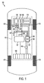
一実施形態において、図1に示すように、本出願は、ハイブリッド車を含む。ハイブリッド車100は、駆動力ユニット105及び車輪170を含む。駆動力ユニット105は、エンジン110、電動発電機191、電動発電機192、バッテリユニット195、バッテリモジュール196、インバータボックス197、ブレーキペダル130、ブレーキペダルセンサ140、変速機120、ハイブリッド制御モジュール107、ボタン180、センサ182及びシフタ184を含む。ハイブリッド制御モジュール107は、メモリ160及びプロセッサ150を含む。
In one embodiment, as shown in FIG. 1, the present application includes a hybrid vehicle. Hybrid vehicle 100 includes a
エンジン110は、主に車輪170を駆動する。エンジン110は、内燃エンジンであってもよい。内燃エンジンは、ガソリン、エタノール、ディーゼル、バイオ燃料又は燃焼に適した他のタイプの燃料といったような燃料を燃焼する。エンジン110によるトルク出力は、変速機120により受信される。電動発電機191と192は、同様に変速機120へトルクを出力することもできる。エンジン110と電動発電機191及び192は、遊星ギヤ(図1に図示しない)を通して連結されてもよい。変速機120は、車輪170に印加トルクを送る。エンジン110によるトルク出力は、車輪170に対する印加トルクに直接転換されない。
電動発電機191及び192は、走行モードでトルクを出力するモーターとして機能し、且つ、再生モードでバッテリユニット195を再充電する発電機として機能する。電動発電機191及び192からの、又は電機191及び192に対して送られる電力は、インバータボックス197を経由してバッテリユニット195を通過する。ブレーキペダルセンサ140は、ブレーキペダル130に加わる圧力を検出でき、車輪170に対する印加トルクにさらに作用しうる。シフタ184は、運転手に前方向と後方向の間で切り替えさせる。
The
センサ182は、ハイブリッド車100の操作を補助しうる1つ又は複数のあらゆるセンサであってもよい。センサ182は、変速機120の出力軸に接続される速度センサであってもよく、プロセッサ150により車両速度に変換される速度入力を検出する。センサ182は、ハイブリッド車の車体に接続される加速度センサであってもよく、減速トルクに応じてハイブリッド車100の実際の減速を検知する。センサ182は、ハイブリッド車100が走行する路面のグレードを検出可能なグレードセンサであってもよい。センサ182は、ハイブリッド車100の位置を検出可能なGPSユニットであってもよい。
The sensor 182 may be any one or a plurality of sensors that can assist the operation of the hybrid vehicle 100. The sensor 182 may be a speed sensor connected to the output shaft of the
ボタン180は、ハイブリッド車100のインストルメントパネル(図1に図示しない)にあるボタンであってもよく、又は、ハンドルの上若しくは近く又はダッシュボードの上のように運転手の手が届く範囲に配置されてもよい。ボタン180は、オン状態及びオフ状態を有するスイッチ又は他の同様な装置であって、オン又はオフの状態を示す信号を送信可能な装置であってもよい。任意の選択で、ボタン180は、オン又はオフとして解釈しうる信号を送信可能な表示スクリーン上のタッチセンサー領域であってもよい。プロセッサ150は、表示スクリーンに接続され、ボタン180からの信号を検知してプリチャージロジックを作動してもよい。
The
変速機120は、ハイブリッド車に適した変速機である。変速機120は、電動発電機191及び192とともにエンジン110と連動する電気式無段変速機(Electrically Controlled Variable Transmission:ECVT)となりうる。変速機120は、エンジン110及び電動発電機191と192の組合せからトルク出力を送ることができる。プロセッサ150は、変速機120を制御し、メモリ160に保存されたデータを用いて車輪170に送られる印加トルクを決定する。例えば、プロセッサ150は、特定の車両スピードで、エンジン110が車輪170に対する印加トルクのごく一部を与えるべきとする一方で、電動発電機191が印加トルクの大部分を与えるべきと決定をしてもよい。プロセッサ150及び変速機120は、車両速度とは無関係にエンジン110のエンジン速度を制御することができる。
The
バッテリユニット195は、車両で利用できる再充電可能なバッテリであり、且つ、複数の電池を含めてもよい。バッテリモジュール196は、バッテリユニット195の充電状態及び/又はハイブリッド車100の充電状態を判定するプロセッサ150に送信される変数を測定可能である。バッテリモジュール196は、バッテリユニット195の電圧、電流、気温、電荷受容性、内部抵抗、自己放電、磁気特性、健康状態及び/又は他の状態又は変数を測定してもよい。他の実施形態において、充電状態は、クーロンカウンティング、量子機構、インピーダンス分光法又は比重計により判定される。他の実施形態において、バッテリモジュール196は、バッテリマネジメントシステム(BMS)であって、内蔵のセンサ及びプロセッサを使用してバッテリユニット195の充電状態を判定する。別の実施形態において、ハイブリッド車100は、BMSを含まなくてもよく、且つ、プロセッサ150は、バッテリモジュール196からのセンサデータを使用してハイブリッド車100の充電状態を判定してもよい。 The battery unit 195 is a rechargeable battery that can be used in a vehicle, and may include a plurality of batteries. The battery module 196 can measure a variable transmitted to the processor 150 that determines the state of charge of the battery unit 195 and / or the state of charge of the hybrid vehicle 100. The battery module 196 may measure the voltage, current, temperature, charge acceptability, internal resistance, self-discharge, magnetic properties, health status and / or other conditions or variables of the battery unit 195. In other embodiments, the state of charge is determined by Coulomb counting, quantum mechanisms, impedance spectroscopy, or a hydrometer. In another embodiment, the battery module 196 is a battery management system (BMS) that uses a built-in sensor and processor to determine the state of charge of the battery unit 195. In another embodiment, the hybrid vehicle 100 may not include a BMS, and the processor 150 may use the sensor data from the battery module 196 to determine the state of charge of the hybrid vehicle 100.
一実施形態において、プロセッサ150は、バッテリユニット195又はハイブリッド車100の現在の充電容量に対して、バッテリユニット195又はハイブリッド車100に保存される電力値に基づき、車両の充電状態のパーセンテージ又は割合を判定してもよい。蓄積エネルギーは、充電、回生ブレーキ又は他の手段を通して得られてもよい。別の実施形態において、充電状態は、バッテリユニット195又はハイブリッド車100のための基準容量に対する蓄積エネルギー値に基づき判定されてもよい。さらに別の実施形態において、充電状態は、バッテリユニット195又はハイブリッド車100と関連付けた別の所定値に対するパーセンテージ又は割合として測定されてもよい。従来技術において知られている充電状態のパーセンテージ、値又は数を判定する他のシステム又は方法は、本開示の範囲を限定することなく使用されてもよい。 In one embodiment, the processor 150 calculates a percentage or percentage of the state of charge of the vehicle based on the power value stored in the battery unit 195 or the hybrid vehicle 100 relative to the current charge capacity of the battery unit 195 or the hybrid vehicle 100. You may judge. The stored energy may be obtained through charging, regenerative braking or other means. In another embodiment, the state of charge may be determined based on a stored energy value relative to a reference capacity for the battery unit 195 or the hybrid vehicle 100. In yet another embodiment, the state of charge may be measured as a percentage or percentage of another predetermined value associated with the battery unit 195 or the hybrid vehicle 100. Other systems or methods for determining the percentage, value or number of state of charge known in the prior art may be used without limiting the scope of the present disclosure.
従来の車両は、トルク変換装置又はクラッチを使用し、後退に切り替えたときにエンジンからのトルクを逆作動する。しかし、ハイブリッド車は、後退ギヤを有しないECVTを使用する。エンジンは、後退ギヤなしで、一方向のみにトルクを生成し、エンジンは、車両を後退するために使用できない。代わりに、電動発電機が遊星ギヤを通して車輪に接続される。逆作動するために、電動発電機は、逆トルクを生成する。エンジンは、ハイブリッド車が後退するときには使用されない。このように、ハイブリッド車は、後退のためにはバッテリ電力にのみ依存する。 Conventional vehicles use a torque converter or clutch and reverse the torque from the engine when switched to reverse. However, hybrid vehicles use ECVT that does not have a reverse gear. The engine generates torque in only one direction without the reverse gear, and the engine cannot be used to reverse the vehicle. Instead, a motor generator is connected to the wheels through the planetary gear. In order to operate in reverse, the motor generator generates reverse torque. The engine is not used when the hybrid vehicle moves backward. Thus, hybrid vehicles rely only on battery power for reversing.
バッテリユニットが十分な充電状態を有するとき、ハイブリッド車は、後退操作を実行してもよい。斜面にある駐車場に後退で並列駐車又は取り付けられたトレーラーとともに後退というように、特定の後退操作は、より多くの電力を必要とし、より高い充電状態を要する。充電状態が不十分なとき、ハイブリッド車は、バッテリユニットを再充電し且つ充電状態を増やすため、通常はエンジンをオンにする。ハイブリッド車は、通常運転中の充電状態を管理し、燃焼効率を考慮しながら最低限の充電状態を維持する。しかし、ハイブリッド車は、運転手が後退走行操作の実行を望むときを予測しない。 When the battery unit has a sufficiently charged state, the hybrid vehicle may perform a reverse operation. Certain retraction operations require more power and require a higher state of charge, such as retreating in parallel to a parking lot on a slope or retreating with a trailer attached. When the state of charge is insufficient, the hybrid vehicle normally turns on the engine to recharge the battery unit and increase the state of charge. The hybrid vehicle manages the state of charge during normal operation and maintains a minimum state of charge while considering combustion efficiency. However, the hybrid vehicle does not predict when the driver desires to perform a reverse travel operation.
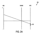
図2Aと図2Bは、エンジン及びMG1とMG2とラベル付けされた2つの電動発電機のトルクの間の関係を示すノモグラフを表す。エンジンは、図1中のエンジン110と対応しえ、MG1及びMG2は、図1中の電動発電機191と192に対応しうる。エンジン、MG1及びMG2は、遊星ギヤにより接続されているので、エンジン、MG1及びMG2は、完全に他から独立してトルクを生成することはできない。より具体的には、エンジン、MG1及びMG2は、遊星ギヤにより接続されているので、これらの要素のうちの一つがそのrpm(revolutions per minute:毎分あたりの回転数)を変化させると、他の要素にも影響する。y軸は、正及び負のrpmに対応する。MG2は、さらに車輪に接続されているので、MG2のrpmもまた、車両速度と直接関係する。MG2が正のrpmを有するとき、車両は前方向に走行する。MG2が負のrpmを有するとき、車両は後退する。矢印は、正又は負のいずれのトルクも描写する。
2A and 2B represent nomographs showing the relationship between the torque of the engine and two motor generators labeled MG1 and MG2. The engine can correspond to the
図2Aは、車両の通常後退のノモグラフ200を表す。エンジンは、車両を後退させる負トルクを生成できず、且つ、それ故に、エンジンが停止する。エンジンは、0rpmを有し、且つ、0トルクを生成する。ハイブリッドシステムは、充電状態を監視し、且つ、バッテリは、通常は後退するための十分な充電状態を有するため、エンジンは、バッテリを再充電する必要がない。変速機の出力軸に接続されたMG2は、ハイブリッド車を後退走行に変える負トルク202を生成する。十分な充電状態で、MG2は、ハイブリッド車が後退操作を実行できる十分な負トルクを生成する。
FIG. 2A represents a
図2Bは、充電状態が後退操作を実行するのに不十分であるときの場合のノモグラフ250を表す。充電状態が低過ぎるとき、ハイブリッドシステムは、通常はエンジンをオンにしてバッテリを再充電する。エンジンは、正のrpmを有し、幾分かの正トルク254を生成する。MG1は、正のrpmと負のトルク252を有するとバッテリを再充電する。しかし、遊星ギヤにより、エンジンが正トルク254を生成し、且つ、MG1が負トルク252を生成するとき、逆トルク258が生成される。MG1からの逆トルク258は、MG2からの所望の負トルク256を効果的に相殺する。完全に相殺されないとしても、負トルク256は、斜面上で後退するとき、逆トルク258及び重力の力の両方に打ち勝つのに不十分であるかもしれない。これは、エンジン回転、MG1及びMG2の回転をもたらすが、ハイブリッド車の動作はもたらさない。このように、ハイブリッド車は、MG1、MG2及びエンジンが作動する間に燃料を燃焼するが、後退走行をするわけではないので、運転手を苦しい状況に置く。運転手は、次いで、シフト操作の選択肢を駐車として放置し、動かないままでバッテリを再充電する。
FIG. 2B represents the
この苦境を防止するために、運転手は、運転手が後退操作を実行する前に、ハイブリッド車100にバッテリユニット195をプリチャージさせたいと思うかもしれない。後退操作を見込んで、運転手は、ハイブリッドシステムにバッテリを充電することを指示したいと思うかもしれないが、現在のハイブリッドシステムは、その選択肢を運転手に与えない。むしろ、運転手は、通常運転から十分にバッテリが充電されることを望んだであろう。さもなければ、運転手は、再充電のために駐車場で無為に時を過ごすことになる。ハイブリッド車100は、手動でプリチャージを強いるという選択肢を運転手に有利に提示し、ハイブリッドシステムの通常のバッテリマネジメントを覆す。 In order to prevent this predicament, the driver may want to have the hybrid vehicle 100 precharge the battery unit 195 before the driver performs the reverse operation. In anticipation of reverse operation, the driver may want to instruct the hybrid system to charge the battery, but current hybrid systems do not give the driver the option. Rather, the driver would have desired that the battery be fully charged from normal operation. Otherwise, the driver will spend time in the parking lot to recharge. The hybrid vehicle 100 advantageously offers the driver the option of manually precharging and overturns the normal battery management of the hybrid system.
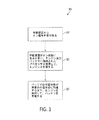
図3は、本開示の一実施形態によるプリチャージの方法を描くフローチャート300を表す。ステップ310は、運転手及び/又はプロセッサ150により作動装置からオン信号を受け取る。ハイブリッド車100において、ボタン180は、オン状態に切換可能であり、あるいはプロセッサ150に信号を送信する。
FIG. 3 depicts a
運転手は、ボタン180を介してプリチャージロジックをオンにする決定をしてもよい。別の実施形態において、プロセッサ150は、特定の条件に合致したときにプリチャージロジックを自動的に作動してもよい。メモリ160は、運転手からの手動入力からの、又は、行動履歴からのいずれかで、プリチャージ機能が共通に使用される位置を保存してもよい。例えば、運転手は、丘の上に住んでいる可能性があり、丘の上で縦列駐車をする前にプリチャージを要する。センサ182は、GPSユニットであってもよく、ハイブリッド車が丘に近付いていくとプロセッサ150に警告する。プロセッサ150は、周辺をさらに考慮して、プリチャージが必要か否かを判定する。例えば、運転手は、センサ182により検出されたトレーラーパークの近くにいる可能性があるが、トレーラーを後退牽引することを見越してプリチャージを始動してもよい。位置を保存することで、プロセッサ150は、その位置の周辺又はその位置にいるときにプリチャージロジックを自動的に開始してもよい。
The driver may decide to turn on the precharge logic via the
プロセッサ150は、運転手が通常帰宅する時刻のように特定の時刻にプリチャージロジックをさらに自動的に開始してもよい。また、プロセッサ150は、センサ182により検出された急峻の程度のように、プリチャージを要し得る他の条件をチェックする。 The processor 150 may further automatically start the precharge logic at a specific time, such as the time when the driver normally returns home. The processor 150 also checks for other conditions that may require precharging, such as the steepness detected by the sensor 182.
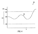
プリチャージロジックを作動することに加えて、運転手は、望ましい充電状態に設定したいと思うかもしれない。ハイブリッドシステムは、図4中の充電状態ウィンドウ410のような通常の充電状態ウィンドウを有し、充電状態ウィンドウは、メモリ160又は無線接続された別のメモリに保存されてもよい。通常の充電状態ウィンドウ又はエリアは、通常の操作中に充電状態を区切る。充電状態が充電状態ウィンドウの最小又は下限閾値に到達したときに、プロセッサ150は、エンジン110を作動してバッテリユニット195を再充電する。充電状態が充電状態ウィンドウの最大又は上限閾値に到達したときに、プロセッサ150は、エンジン110をオフにしてバッテリユニット195の充電を停止する。充電状態ウィンドウは、事前に決定され、且つ、バッテリユニット195の寿命を最大にすることに基づき設定してもよい。充電状態ウィンドウは、事前にベンチテストされ、且つ、通常の走行操作に適するものが決定されてもよい。
In addition to activating the precharge logic, the driver may want to set the desired charge state. The hybrid system has a normal charge state window, such as the charge state window 410 in FIG. 4, which may be stored in the memory 160 or another wirelessly connected memory. The normal charge state window or area delimits the charge state during normal operation. When the state of charge reaches the minimum or lower threshold of the state of charge window, the processor 150 operates the
所要の充電状態は、充電状態ウィンドウの上限閾値と同じであってもよい。しかし、運転手は、図4中の所要の充電状態420のように、所要の充電状態を上限閾値を超えて設定したいと思うかもしれない。運転手は、ハイブリッド車100内のインターフェースを介して設定してもよく、又は、プリチャージロジックは、事前に設定された過充電閾値を有してもよい。運転手は、過充電がバッテリユニット195の寿命に悪影響を及ぼし得ることについて通知される義務があってもよい。 The required state of charge may be the same as the upper threshold of the state of charge window. However, the driver may want to set the required charge state beyond the upper threshold, such as the required charge state 420 in FIG. The driver may be set via an interface in the hybrid vehicle 100, or the precharge logic may have a pre-set overcharge threshold. The driver may be obliged to be informed that overcharging can adversely affect the life of the battery unit 195.
図3に戻ると、ステップ320で、ボタン180がオン状態にあるときに、プロセッサ150は、エンジン110を作動する。プリチャージロジックが作動すると、故にプロセッサ150は、バッテリユニット195を充電するためにエンジン110をオンにする。
Returning to FIG. 3, at
ステップ330で、バッテリユニット195は、充電状態が所要の充電状態に到達するまで、エンジン110により充電される。所要の充電状態は、通常の充電状態ウィンドウの上限閾値、又は、バッテリ195が過充電となるようなより高い充電状態であってもよい。一旦バッテリユニット195が所要の充電状態に到達すると、プリチャージロジックは停止され、且つ、エンジンは切られて充電を停止してもよい。
In
また、運転手は、プリチャージを早めに終了する選択肢を有する。運転手は、ボタン180を押してオフ状態にする。プリローンチロジックは、次いで停止される。また、エンジン110は切られて充電を停止する。しかし、通常のハイブリッドシステムロジックは、通常のハイブリッドシステムロジックに従い、エンジン110を維持して充電を続ける決定をしてもよい。
The driver also has an option to finish precharging early. The driver presses the
図4は、充電状態レベルの変化を図示する充電状態グラフ400を表す。充電状態ウィンドウは、40%と80%の間にある。ハイブリッドシステムは、充電状態が60%を下回ると大抵は充電され、又は、それを超えると大抵は充電されなくなるように、維持することが望ましい充電状態レベルとして60%を設定してもよい。別の実施形態において、充電状態ウィンドウは、複数の異なる閾値を有してもよく、且つ、望ましい充電状態レベルは、必要に応じて異なる値としてもよい。
FIG. 4 represents a state of
充電状態曲線430により示すように、充電状態レベルは、ハイブリッド車が走行するにつれて変動する。時刻t0の時点で、運転手は、ボタン180を押してプリチャージロジックを作動する。充電状態レベルは、所要の充電状態420、図4中の90%まで上昇する。このように、プリチャージロジックは、望ましいレベルまで充電状態を運転手に手動で充電させ、充電状態ウィンドウ410を超えてもよい。所要の充電状態420により、ハイブリッド車は、後退操作を実行することができる。
As shown by the charge state curve 430, the state of charge varies as the hybrid vehicle travels. At time t 0 , the driver presses
当業者は、本明細書中に開示された実施例と関連して記載されたロジカルブロック、モジュール及びアルゴリズムステップのあらゆる具体例が、電子機器、コンピュータソフトウェア又は両方の組合せとして実装されてもよいことを理解する。さらに、本発明は、プロセッサ又はコンピュータに特定の機能を実施又は実行させる機械可読媒体にも組み込むことができる。 Those skilled in the art will appreciate that any specific examples of logical blocks, modules, and algorithm steps described in connection with the embodiments disclosed herein may be implemented as electronic equipment, computer software, or a combination of both. To understand the. Furthermore, the present invention may also be incorporated into machine readable media that cause a processor or computer to perform or perform certain functions.
ハードウェアとソフトウェアの互換性を明確に説明するために、あらゆる具体的な構成要素、ブロック、モジュール、回路及びステップは、これらの機能性に関し、概して上述された。かかる機能性は、ハードウェア又はソフトウェアとして実装され、特定のアプリケーション及びシステム全体に課される設計上の制約に依存する。熟練の技術者は、各々の実施形態について異なる方法で記載された機能性を実装するかもしれないが、このような実装判断は、開示された装置及び方法の範囲からの逸脱を招くものとして解釈されるべきではない。 In order to clearly describe the compatibility of hardware and software, all specific components, blocks, modules, circuits and steps have been generally described above with respect to their functionality. Such functionality is implemented as hardware or software and depends on the particular application and design constraints imposed on the overall system. Skilled technicians may implement the functionality described in different ways for each embodiment, but such implementation decisions are interpreted as causing deviations from the scope of the disclosed apparatus and method. Should not be done.
本明細書中に開示された実施例と関連して説明されたあらゆる具体的なロジカルブロック、ユニット、モジュール及び回路は、本明細書に記載の複数の機能を実行するように設計された汎用プロセッサ、デジタルシグナルプロセッサ(DSP)、特定用途向け集積回路(Application Specific Integrated Circuit:ASIC)、FPGA(フィールド・プログラマブル・ゲート・アレイ)又は他のプログラム可能なロジックデバイス、個別のゲート、トランジスタロジック、個別のハードウェア構成要素、又はこれらのいずれかの組合せとともに、実装され又は実行されてもよい。汎用プロセッサは、マイクロプロセッサであってもよいが、選択的に、プロセッサは、いかなる従来のプロセッサ、コントローラ、マイクロコントローラ又はステートマシンであってもよい。また、プロセッサは、計算装置の組合せとして実装されてもよく、例えば、DSPとマイクロプロセッサの組合せ、複数のマイクロプロセッサ、DSPコアと連動する1つ又は複数のマイクロプロセッサ、又は、その他このような設計として実装されてもよい。 Any specific logical blocks, units, modules, and circuits described in connection with the embodiments disclosed herein are general purpose processors designed to perform the functions described herein. , Digital signal processor (DSP), application specific integrated circuit (ASIC), FPGA (field programmable gate array) or other programmable logic device, individual gate, transistor logic, individual It may be implemented or executed with hardware components, or any combination thereof. A general purpose processor may be a microprocessor, but in the alternative, the processor may be any conventional processor, controller, microcontroller, or state machine. The processor may also be implemented as a combination of computing devices, for example, a combination of a DSP and a microprocessor, a plurality of microprocessors, one or more microprocessors in conjunction with a DSP core, or other such design. May be implemented as
本明細書中に開示された実施例と関連して説明された方法又はアルゴリズムの複数のステップは、ハードウェアの中、プロセッサにより実行されるソフトウェアモジュールの中、又はこの2つの組合せの中に直接組み込まれてもよい。方法又はアルゴリズムの複数のステップは、実施例中で与えられた順番から交互に実行されてもよい。ソフトウェアモジュールは、RAMメモリ、フラッシュメモリ、ROMメモリ、EPROMメモリ、EEPROMメモリ、レジスタ、ハードディスク、リムーバブルディスク、CD−ROM又は他のいかなる形態をした従来の記憶媒体に内在してもよい。典型的な記憶媒体は、プロセッサが記憶媒体からの、又は、に対して情報を読み取る又は書き込むことができるようにプロセッサと接続している。別の実施形態において、記憶媒体は、プロセッサと一体化されていてもよい。プロセッサと記憶媒体は、特定用途向け集積回路に内在してもよい。特定用途向け集積回路は、ワイヤレスモデムに内在してもよい。別の実施形態において、プロセッサと記憶媒体は、ワイヤレスモデムの中に別個の構成要素として内在してもよい。 The steps of the method or algorithm described in connection with the embodiments disclosed herein can be performed directly in hardware, in a software module executed by a processor, or in a combination of the two. May be incorporated. The steps of the method or algorithm may be performed alternately from the order given in the examples. The software module may reside in RAM memory, flash memory, ROM memory, EPROM memory, EEPROM memory, registers, hard disk, removable disk, CD-ROM or any other conventional storage medium. An exemplary storage medium is coupled to the processor such that the processor can read information from, and write information to, and from the storage medium. In other embodiments, the storage medium may be integral to the processor. The processor and the storage medium may reside in an application specific integrated circuit. An application specific integrated circuit may reside in the wireless modem. In another embodiment, the processor and the storage medium may reside as separate components in the wireless modem.
開示された実施例についての先の説明は、開示された方法や装置を当業者に製造又は使用可能にさせるために与えられる。これらの実施例に対するあらゆる変更は、当業者にとって明白であり、且つ、本明細書中に定義された原理は、開示の方法及び装置の精神又は範囲から逸脱することなく、他の実施例に適用されてもよい。説明された実施形態は、全側面における具体例としてのみに考えられ、且つ、限定的ではなく、発明の範囲は、それ故に、前述の明細書よりもむしろ添付のクレームにより示される。クレームと同等の意味及び範囲内になる全ての変更は、これらの範囲内に包含される。 The previous description of the disclosed embodiments is provided to enable any person skilled in the art to make or use the disclosed methods and apparatus. Any changes to these embodiments will be apparent to those skilled in the art and the principles defined herein may be applied to other embodiments without departing from the spirit or scope of the disclosed methods and apparatus. May be. The described embodiments are only considered as specific examples in all aspects and are not limiting, the scope of the invention is therefore indicated by the appended claims rather than the foregoing specification. All changes that come within the meaning and scope of the claims are encompassed within these scopes.
Claims (20)
充電状態を有するバッテリと、
前記バッテリに接続され且つ前記バッテリを充電するように構成されたエンジンと、
オン状態及びオフ状態を有する作動装置と、
前記バッテリ及び前記エンジンに接続され、且つ、前記作動装置がオン状態に切り替えられたときに、前記充電状態が所要の充電状態に到達するまで前記バッテリを充電するために、前記エンジンを作動するように構成されたプロセッサと、
を有するシステム。 A system for precharging a hybrid vehicle,
A battery having a charged state;
An engine connected to and configured to charge the battery;
An actuator having an on state and an off state;
When connected to the battery and the engine and when the operating device is switched on, the engine is operated to charge the battery until the state of charge reaches a required state of charge. A processor configured with
Having a system.
充電状態を有するバッテリと、
前記バッテリを充電するように構成されたエンジンと、
オン状態及びオフ状態を有する作動装置と、
前記作動装置がオン状態に切り替えられたときに、前記充電状態が所要の充電状態に到達するまで、前記エンジンを作動するように構成されたプロセッサと、
を有する車。 A hybrid vehicle,
A battery having a charged state;
An engine configured to charge the battery;
An actuator having an on state and an off state;
A processor configured to operate the engine until the state of charge reaches a required state of charge when the actuating device is switched to an on state;
Car with.
作動装置からのオン信号を受け取るステップと、
エンジン及びバッテリと連動したプロセッサを使用して、前記作動装置がオン状態のときに、前記エンジンを作動するステップと、
前記エンジンを使用して、前記バッテリの充電状態が所要の充電状態に到達するまで、前記バッテリを充電するステップと、
を有する方法。 A method for precharging a hybrid vehicle,
Receiving an on signal from the actuator;
Using a processor in conjunction with an engine and a battery to operate the engine when the actuator is on;
Charging the battery using the engine until the state of charge of the battery reaches a required state of charge; and
Having a method.
Applications Claiming Priority (3)
| Application Number | Priority Date | Filing Date | Title |
|---|---|---|---|
| US14/066,609 US9428173B2 (en) | 2013-10-29 | 2013-10-29 | Vehicle battery pre-charge feature |
| US14/066,609 | 2013-10-29 | ||
| PCT/US2014/062129 WO2015065830A1 (en) | 2013-10-29 | 2014-10-24 | Vehicle battery pre-charge feature |
Related Child Applications (1)
| Application Number | Title | Priority Date | Filing Date |
|---|---|---|---|
| JP2019103730A Division JP6853301B2 (en) | 2013-10-29 | 2019-06-03 | Vehicle battery precharge function |
Publications (2)
| Publication Number | Publication Date |
|---|---|
| JP2017501067A true JP2017501067A (en) | 2017-01-12 |
| JP2017501067A5 JP2017501067A5 (en) | 2018-09-13 |
Family
ID=52996295
Family Applications (2)
| Application Number | Title | Priority Date | Filing Date |
|---|---|---|---|
| JP2016527399A Withdrawn JP2017501067A (en) | 2013-10-29 | 2014-10-24 | Vehicle battery precharge function |
| JP2019103730A Active JP6853301B2 (en) | 2013-10-29 | 2019-06-03 | Vehicle battery precharge function |
Family Applications After (1)
| Application Number | Title | Priority Date | Filing Date |
|---|---|---|---|
| JP2019103730A Active JP6853301B2 (en) | 2013-10-29 | 2019-06-03 | Vehicle battery precharge function |
Country Status (6)
| Country | Link |
|---|---|
| US (1) | US9428173B2 (en) |
| EP (1) | EP3063031A4 (en) |
| JP (2) | JP2017501067A (en) |
| KR (1) | KR102065494B1 (en) |
| CN (1) | CN105682963B (en) |
| WO (1) | WO2015065830A1 (en) |
Families Citing this family (17)
| Publication number | Priority date | Publication date | Assignee | Title |
|---|---|---|---|---|
| JP2015116967A (en) * | 2013-12-19 | 2015-06-25 | トヨタ自動車株式会社 | Hybrid vehicle |
| WO2016003461A1 (en) * | 2014-07-02 | 2016-01-07 | Cummins Inc. | Engine start/stop function management |
| BR112017026235B1 (en) * | 2015-06-08 | 2022-10-04 | Nissan Motor Co., Ltd | POWER GENERATION CONTROL DEVICE FOR A HYBRID VEHICLE |
| CN106891744B (en) * | 2015-12-18 | 2019-11-08 | 比亚迪股份有限公司 | The control method of electric car and its onboard charger and onboard charger |
| CN106891745B (en) * | 2015-12-18 | 2019-11-05 | 比亚迪股份有限公司 | The control method of electric car and its onboard charger and onboard charger |
| CN106891748B (en) * | 2015-12-18 | 2019-02-26 | 比亚迪股份有限公司 | The control method of electric car and its onboard charger and onboard charger |
| DE102016203401A1 (en) * | 2016-03-02 | 2017-09-07 | Bayerische Motoren Werke Aktiengesellschaft | Method and device for operating a vehicle having an electrical energy storage hybrid vehicle with an electric motor and with an internal combustion engine |
| US10239416B2 (en) * | 2016-06-22 | 2019-03-26 | Ford Global Technologies, Llc | System and method for improving reverse driving capability of electrified vehicles |
| KR101836289B1 (en) * | 2016-10-21 | 2018-04-19 | 현대자동차 주식회사 | Engine clutch cotrolling apparatus for green car and method of thesame |
| US10766478B2 (en) * | 2017-02-17 | 2020-09-08 | Hyliion Inc. | Tractor unit with on-board regenerative braking energy storage for stopover HVAC operation without engine idle |
| DE102017210155A1 (en) | 2017-06-19 | 2018-12-20 | Robert Bosch Gmbh | Charging method for a rechargeable electrochemical energy store |
| US10118604B1 (en) | 2017-07-07 | 2018-11-06 | Toyota Motor Engineering & Manufacturing North America, Inc. | System and method for improved battery pre-charge and deactivation timing in traffic |
| JP6958286B2 (en) * | 2017-11-24 | 2021-11-02 | トヨタ自動車株式会社 | Vehicle and power control system |
| KR102602984B1 (en) * | 2018-07-23 | 2023-11-16 | 현대자동차주식회사 | Method for controlling state of charge of motor-driven vehicle without reverse gear |
| JP7147585B2 (en) * | 2019-01-23 | 2022-10-05 | トヨタ自動車株式会社 | vehicle controller |
| CN110293907B (en) * | 2019-06-25 | 2021-01-19 | 浙江吉利控股集团有限公司 | Reverse gear reminding method and device, vehicle and terminal |
| US11708007B2 (en) * | 2021-08-02 | 2023-07-25 | Ford Global Technologies, Llc | Control systems and methods for modifying a battery state of charge signal |
Citations (7)
| Publication number | Priority date | Publication date | Assignee | Title |
|---|---|---|---|---|
| JP2001003779A (en) * | 1999-06-17 | 2001-01-09 | Aichi Corp | Electrically-driven working vehicle |
| US20050080523A1 (en) * | 2003-10-14 | 2005-04-14 | Bennett Adam C. | Silent operating mode for reducing emissions of a hybrid electric vehicle |
| WO2008041319A1 (en) * | 2006-10-03 | 2008-04-10 | Mitsubishi Electric Corporation | Hybrid vehicle |
| JP2008291791A (en) * | 2007-05-25 | 2008-12-04 | Toyota Motor Corp | Parking support device |
| JP2010274805A (en) * | 2009-05-29 | 2010-12-09 | Honda Motor Co Ltd | Power device |
| JP2011219039A (en) * | 2010-04-13 | 2011-11-04 | Toyota Motor Corp | Hybrid drive device for vehicle |
| JP2014187853A (en) * | 2013-03-25 | 2014-10-02 | Toyota Motor Corp | Vehicle |
Family Cites Families (32)
| Publication number | Priority date | Publication date | Assignee | Title |
|---|---|---|---|---|
| JP3484251B2 (en) | 1995-02-06 | 2004-01-06 | 本田技研工業株式会社 | Battery charging control device for electric vehicles |
| JP3880752B2 (en) | 1999-08-06 | 2007-02-14 | 本田技研工業株式会社 | Engine automatic start / stop control device |
| JP3529680B2 (en) * | 1999-10-13 | 2004-05-24 | 本田技研工業株式会社 | Motor control device for hybrid vehicle |
| US6483198B2 (en) | 2001-01-19 | 2002-11-19 | Transportation Techniques Llc | Hybrid electric vehicle having a selective zero emission mode, and method of selectively operating the zero emission mode |
| US7224132B2 (en) * | 2004-01-22 | 2007-05-29 | Wavecrest Laboratories, Llc. | Portable range extender operable in automatic and manual modes |
| US7545121B2 (en) * | 2004-12-15 | 2009-06-09 | Bolduc Scott A | Auxiliary vehicle power supply |
| US7434636B2 (en) | 2005-03-18 | 2008-10-14 | Sutherland Danilo R | Power system for electric and hybrid vehicles |
| JP4572712B2 (en) * | 2005-03-25 | 2010-11-04 | トヨタ自動車株式会社 | Vehicle and control method thereof |
| US7665559B2 (en) | 2005-06-10 | 2010-02-23 | De La Torre-Bueno Jose | Inputs for optimizing performance in hybrid vehicles |
| DE112007000515T5 (en) | 2006-03-06 | 2009-01-15 | GM Global Technology Operations, Inc., Detroit | Method and apparatus for controlling a hybrid vehicle powertrain |
| US8565969B2 (en) * | 2007-04-03 | 2013-10-22 | Clean Emissions Technologies, Inc. | Over the road/traction/cabin comfort retrofit |
| US20080185198A1 (en) | 2007-02-02 | 2008-08-07 | Steven Mark Jones | Next generation hybrid III parallel/series hybrid system |
| WO2008098230A1 (en) * | 2007-02-09 | 2008-08-14 | A123 Systems , Inc. | Control system and hybrid vehicles with reconfigurable multi-function power converter |
| DE102007020196A1 (en) * | 2007-04-28 | 2008-10-30 | Voith Patent Gmbh | Method for controlling the state of charge of an energy store for a vehicle with hybrid drive |
| JP4807329B2 (en) * | 2007-06-14 | 2011-11-02 | トヨタ自動車株式会社 | Hybrid vehicle and hybrid vehicle operation system |
| KR20100125430A (en) * | 2008-03-19 | 2010-11-30 | 제로 에미션 시스템즈, 인코포레이티드 | Electric traction system and method |
| JP2010120597A (en) * | 2008-11-21 | 2010-06-03 | Yamaha Motor Co Ltd | Vehicle |
| US8314578B2 (en) * | 2009-03-09 | 2012-11-20 | GM Global Technology Operations LLC | Control of an alternator-starter for a hybrid electric vehicle having a disconnected high-voltage battery |
| JP2010221745A (en) * | 2009-03-19 | 2010-10-07 | Toyota Motor Corp | Vehicle control device |
| EP2308708B1 (en) | 2009-09-16 | 2016-08-17 | swissauto powersport llc | Electric vehicle with range extension |
| WO2011037211A1 (en) * | 2009-09-28 | 2011-03-31 | 本田技研工業株式会社 | Power output device |
| KR101030910B1 (en) * | 2009-10-19 | 2011-04-22 | 에스비리모티브 주식회사 | Battery management system and driving method thereof |
| JP5418785B2 (en) | 2010-06-03 | 2014-02-19 | 三菱自動車工業株式会社 | Storage control device for hybrid vehicle |
| DE102010031289B4 (en) | 2010-07-13 | 2015-08-20 | Bayerische Motoren Werke Aktiengesellschaft | Hybrid or electric vehicle with different operating programs |
| US8499201B1 (en) * | 2010-07-22 | 2013-07-30 | Altera Corporation | Methods and systems for measuring and presenting performance data of a memory controller system |
| JP5238792B2 (en) * | 2010-11-17 | 2013-07-17 | 本田技研工業株式会社 | On-vehicle navigation device and server device |
| US9079586B2 (en) | 2011-02-17 | 2015-07-14 | Ford Global Technologies, Llc | Method and system for extending an operating range of a motor vehicle |
| DE102011104443A1 (en) * | 2011-06-17 | 2012-02-16 | Daimler Ag | Method for operating hybrid vehicle, involves coupling internal combustion engine with electric machine that is used in charging operation as generator for feeding storage unit with electrical energy |
| DE102011051439A1 (en) | 2011-06-29 | 2013-01-03 | Dr. Ing. H.C. F. Porsche Aktiengesellschaft | Drive system for a plug-in hybrid motor vehicle |
| DE102011106958A1 (en) | 2011-07-08 | 2013-01-10 | Gm Global Technology Operations, Llc | Method for operating a vehicle and vehicle |
| WO2013090543A1 (en) * | 2011-12-15 | 2013-06-20 | Ego-Gear, Llc | A device to increase fuel economy |
| US9637019B2 (en) * | 2012-01-09 | 2017-05-02 | GM Global Technology Operations LLC | System and method for charging a plug-in electric vehicle |
-
2013
- 2013-10-29 US US14/066,609 patent/US9428173B2/en active Active
-
2014
- 2014-10-24 EP EP14857356.1A patent/EP3063031A4/en active Pending
- 2014-10-24 WO PCT/US2014/062129 patent/WO2015065830A1/en active Application Filing
- 2014-10-24 KR KR1020167014248A patent/KR102065494B1/en active IP Right Grant
- 2014-10-24 CN CN201480059575.9A patent/CN105682963B/en active Active
- 2014-10-24 JP JP2016527399A patent/JP2017501067A/en not_active Withdrawn
-
2019
- 2019-06-03 JP JP2019103730A patent/JP6853301B2/en active Active
Patent Citations (7)
| Publication number | Priority date | Publication date | Assignee | Title |
|---|---|---|---|---|
| JP2001003779A (en) * | 1999-06-17 | 2001-01-09 | Aichi Corp | Electrically-driven working vehicle |
| US20050080523A1 (en) * | 2003-10-14 | 2005-04-14 | Bennett Adam C. | Silent operating mode for reducing emissions of a hybrid electric vehicle |
| WO2008041319A1 (en) * | 2006-10-03 | 2008-04-10 | Mitsubishi Electric Corporation | Hybrid vehicle |
| JP2008291791A (en) * | 2007-05-25 | 2008-12-04 | Toyota Motor Corp | Parking support device |
| JP2010274805A (en) * | 2009-05-29 | 2010-12-09 | Honda Motor Co Ltd | Power device |
| JP2011219039A (en) * | 2010-04-13 | 2011-11-04 | Toyota Motor Corp | Hybrid drive device for vehicle |
| JP2014187853A (en) * | 2013-03-25 | 2014-10-02 | Toyota Motor Corp | Vehicle |
Also Published As
| Publication number | Publication date |
|---|---|
| US9428173B2 (en) | 2016-08-30 |
| JP6853301B2 (en) | 2021-03-31 |
| CN105682963B (en) | 2018-05-15 |
| KR102065494B1 (en) | 2020-01-13 |
| KR20160078462A (en) | 2016-07-04 |
| EP3063031A1 (en) | 2016-09-07 |
| US20150120104A1 (en) | 2015-04-30 |
| EP3063031A4 (en) | 2017-12-20 |
| JP2019194077A (en) | 2019-11-07 |
| CN105682963A (en) | 2016-06-15 |
| WO2015065830A1 (en) | 2015-05-07 |
Similar Documents
| Publication | Publication Date | Title |
|---|---|---|
| JP6853301B2 (en) | Vehicle battery precharge function | |
| US11180149B2 (en) | Vehicle and method for controlling the same | |
| JP4514725B2 (en) | Vehicle driving power switching control method | |
| JP5843412B2 (en) | Accelerator pedal reaction force control device and vehicle | |
| JP6156419B2 (en) | vehicle | |
| JP2018509880A (en) | Method and apparatus for determining the value of the energy state of a battery in an automobile | |
| US11338701B2 (en) | Eco-friendly vehicle and method of providing guidance for charging amount | |
| CN103660972A (en) | Method and system for charging battery for hybrid electric vehicle | |
| WO2009064092A2 (en) | System and method for driving hybrid electric vehicle | |
| US9150111B1 (en) | Engine-generator control method and series hybrid electric combat maneuvering system using the same | |
| JP2019162955A (en) | Hybrid vehicle | |
| JP2006077641A (en) | Control device for hybrid electric automobile | |
| JP6194152B2 (en) | Vehicle control device | |
| JP2009184647A (en) | Driving control device for parallel-hybrid vehicle | |
| JP2008132837A (en) | Hybrid vehicle | |
| JP2012232671A (en) | Vehicle | |
| CN112389416A (en) | Vehicle control device and vehicle | |
| WO2012137301A1 (en) | Vehicle and method for controlling same | |
| US11601005B2 (en) | Hybrid electric vehicle and charge control method therefor | |
| JP2012219795A (en) | Vehicle and control method of the same | |
| US20200361474A1 (en) | Electric vehicle | |
| JP2012060844A (en) | Vehicle | |
| WO2014038442A1 (en) | Hybrid vehicle control apparatus | |
| JP6442553B2 (en) | Vehicle control device | |
| WO2011142022A1 (en) | Hybrid vehicle control device and hybrid vehicle |
Legal Events
| Date | Code | Title | Description |
|---|---|---|---|
| A621 | Written request for application examination |
Free format text: JAPANESE INTERMEDIATE CODE: A621 Effective date: 20170906 |
|
| A977 | Report on retrieval |
Free format text: JAPANESE INTERMEDIATE CODE: A971007 Effective date: 20180426 |
|
| A131 | Notification of reasons for refusal |
Free format text: JAPANESE INTERMEDIATE CODE: A131 Effective date: 20180508 |
|
| A524 | Written submission of copy of amendment under article 19 pct |
Free format text: JAPANESE INTERMEDIATE CODE: A524 Effective date: 20180806 |
|
| A02 | Decision of refusal |
Free format text: JAPANESE INTERMEDIATE CODE: A02 Effective date: 20190205 |
|
| A521 | Request for written amendment filed |
Free format text: JAPANESE INTERMEDIATE CODE: A523 Effective date: 20190603 |
|
| A911 | Transfer to examiner for re-examination before appeal (zenchi) |
Free format text: JAPANESE INTERMEDIATE CODE: A911 Effective date: 20190611 |
|
| A912 | Re-examination (zenchi) completed and case transferred to appeal board |
Free format text: JAPANESE INTERMEDIATE CODE: A912 Effective date: 20190705 |
|
| A761 | Written withdrawal of application |
Free format text: JAPANESE INTERMEDIATE CODE: A761 Effective date: 20190724 |