JP2017223263A5 - - Google Patents
Download PDFInfo
- Publication number
- JP2017223263A5 JP2017223263A5 JP2016117840A JP2016117840A JP2017223263A5 JP 2017223263 A5 JP2017223263 A5 JP 2017223263A5 JP 2016117840 A JP2016117840 A JP 2016117840A JP 2016117840 A JP2016117840 A JP 2016117840A JP 2017223263 A5 JP2017223263 A5 JP 2017223263A5
- Authority
- JP
- Japan
- Prior art keywords
- valve
- peripheral surface
- male screw
- motor
- valve body
- Prior art date
- Legal status (The legal status is an assumption and is not a legal conclusion. Google has not performed a legal analysis and makes no representation as to the accuracy of the status listed.)
- Granted
Links
- 230000002093 peripheral Effects 0.000 claims description 9
- 229910001369 Brass Inorganic materials 0.000 claims description 2
- 230000037250 Clearance Effects 0.000 claims description 2
- 239000010951 brass Substances 0.000 claims description 2
- 230000035512 clearance Effects 0.000 claims description 2
- 229910001220 stainless steel Inorganic materials 0.000 claims description 2
- 239000010935 stainless steel Substances 0.000 claims description 2
- 230000000875 corresponding Effects 0.000 claims 1
- 239000012530 fluid Substances 0.000 description 3
- 230000001429 stepping Effects 0.000 description 3
- 239000003507 refrigerant Substances 0.000 description 2
- 230000035611 feeding Effects 0.000 description 1
- 238000005057 refrigeration Methods 0.000 description 1
- 238000003466 welding Methods 0.000 description 1
Images
Description
従来、パッケージエアコン、ルームエアコン、冷凍機などに用いられる電動弁が知られている(例えば、特許文献1)。この電動弁においては、図7に示すように、ステッピングモータが駆動してロータ103が回転すると、雌ねじ131aと雄ねじ121aのねじ送り作用により、動軸102を介して弁体114が軸L方向に移動する。これにより、弁体114を開閉する調整がなされ、管継手111から流入して管継手112から流出する冷媒の流量が制御される。 Conventionally, an electric valve used for a package air conditioner, a room air conditioner, a refrigerator, and the like is known (for example, Patent Document 1). In this electric valve, as shown in FIG. 7, when the stepping motor is driven and the rotor 103 rotates, the valve element 114 is moved in the axis L direction via the moving shaft 102 by the screw feeding action of the female screw 131a and the male screw 121a. Moving. Thereby, adjustment which opens and closes the valve body 114 is made, and the flow rate of the refrigerant flowing in from the pipe joint 111 and flowing out from the pipe joint 112 is controlled.
なお、この電動弁においては、弁体114を弁閉方向に最大限移動させた状態においても、図8に示すように、弁ポート121と弁体114との間に僅かな隙間123が形成され、この時が最小弁開状態となるように設計がなされている。このため、最小弁開状態においても、流体がわずかに隙間123を通じて流れることが許容され、圧縮機の低周波数運転に追従した流量を確保することができる。また、冷媒が冷凍サイクル中を常に循環することが可能となるため、圧縮機の焼損を防止することができる。 In this motor-operated valve, a slight gap 123 is formed between the valve port 121 and the valve body 114 as shown in FIG. 8 even when the valve body 114 is moved to the maximum in the valve closing direction . At this time, the valve is designed to be in the minimum valve open state. Therefore, even at the minimum valve open state, is allowed fluid to flow slightly through the gap 123, it is possible to ensure the flow rate to follow the low frequency operation of the compressor. Further, since the refrigerant can always circulate in the refrigeration cycle, the compressor can be prevented from being burned out.
上記目的を達成するための本発明の電動弁は、
ロータの回転運動を、雄ネジ部材と雌ネジ部材とのネジ螺合により直線運動に変換し、この直線運動に基づいて弁本体内に収容された弁体を軸方向に移動させる電動弁であって、
前記弁体が、弁ポートに挿入された場合に前記弁ポートの前記内周面との間に微小なクリアランスを形成する不感態部と、
前記不感態部と連続して形成されたテーパー状の外周面を有する先端部と
を備え、
前記弁ポートに挿入された前記不感態部の高さが、前記ネジ螺合時のネジガタ分の高さよりも高く形成されていることを特徴とする。
To achieve the above object, the motor-operated valve of the present invention is
This is an electric valve that converts the rotational motion of the rotor into a linear motion by screwing the male screw member and the female screw member, and moves the valve element accommodated in the valve body in the axial direction based on this linear motion. And
An insensitive portion that forms a minute clearance with the inner peripheral surface of the valve port when the valve body is inserted into the valve port ;
A tip portion having a tapered outer peripheral surface formed continuously with the insensitive portion, and
A height of the insensitive portion inserted into the valve port is formed to be higher than a height of a screw play at the time of the screwing.
これにより、最小弁開状態において流体を正方向に通過させたときと、流体を逆方向に通過させたときの流量の差をなくすことができ、省エネ性の問題を解決することができる。
また、本発明の電動弁は、
前記弁体がステンレスまたは真鍮で形成されていることを特徴とする。
また、本発明の電動弁は、
前記弁本体に固定され、前記雌ネジ部材として機能する支持部材と、
前記ロータに固着され、前記雄ネジ部材として機能するオネジ軸と
を備え、
前記弁体は、前記弁本体に配設された弁座部材の方向に付勢した状態で前記オネジ軸に保持されていることを特徴とする。
As a result, the difference in flow rate between when the fluid is passed in the forward direction and when the fluid is passed in the reverse direction in the minimum valve open state can be eliminated, and the problem of energy saving can be solved.
Moreover, the motor operated valve of the present invention is
The valve body is made of stainless steel or brass.
Moreover, the motor operated valve of the present invention is
A support member fixed to the valve body and functioning as the female screw member;
A male screw shaft fixed to the rotor and functioning as the male screw member;
With
The valve body is held by the male screw shaft in a state of being biased in the direction of a valve seat member disposed in the valve body.
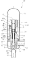
弁本体1の上端には、図示しないステッピングモータのケース61が溶接等によって気密に固定されている。ケース61内には外周部を多極に着磁されたマグネットロータ62が回転可能に設けられている。また、ケース61の外周には、図示しないステータコイルが配設されており、ステッピングモータは、ステータコイルにパルス信号が与えられることにより、そのパルス数に応じてマグネットロータ62を回転させる。マグネットロータ62は嵌合孔62aと回転止め部(図示せず)を有している。そして、嵌合孔62aをオネジ軸4の大径部41に嵌合するとともに、オネジ軸4のフランジ部41bの切り欠き部に回転止め部を係合させ、さらに、ばね受金具45を大径部41の端部に圧入し、溶着することにより、マグネットロータ62がオネジ軸4に固着されている。
A
Claims (5)
前記弁体は、弁ポートに挿入した場合に前記弁ポートの前記内周面との間に微小なクリアランスを形成する不感態部と、
前記不感態部と連続して形成されたテーパー状の外周面を有する先端部と
を備え、
前記弁ポートに挿入された前記不感態部の高さは、前記ネジ螺合時のネジガタ分の高さよりも高く形成されていることを特徴とする電動弁。 This is an electric valve that converts the rotational motion of the rotor into a linear motion by screwing the male screw member and the female screw member, and moves the valve element accommodated in the valve body in the axial direction based on this linear motion. And
The valve body, when inserted into a valve port, an insensitive portion that forms a minute clearance with the inner peripheral surface of the valve port ;
A tip portion having a tapered outer peripheral surface formed continuously with the insensitive portion, and
The motor-operated valve, wherein a height of the insensitive portion inserted into the valve port is formed to be higher than a height corresponding to a screw play at the time of screwing.
前記ロータに固着され、前記雄ネジ部材として機能するオネジ軸とA male screw shaft fixed to the rotor and functioning as the male screw member;
を備え、With
前記弁体は、前記弁本体に配設された弁座部材の方向に付勢した状態で前記オネジ軸に保持されていることを特徴とする請求項1〜4の何れか一項に記載の電動弁。The said valve body is hold | maintained at the said male screw shaft in the state urged | biased in the direction of the valve seat member arrange | positioned at the said valve main body, The Claim 1 characterized by the above-mentioned. Motorized valve.
Priority Applications (4)
| Application Number | Priority Date | Filing Date | Title |
|---|---|---|---|
| JP2016117840A JP6359593B2 (en) | 2016-06-14 | 2016-06-14 | Motorized valve |
| PCT/JP2017/016022 WO2017217114A1 (en) | 2016-06-14 | 2017-04-21 | Electric valve |
| CN202110648153.7A CN113494619B (en) | 2016-06-14 | 2017-04-21 | Electric valve |
| CN201780033172.0A CN109219716B (en) | 2016-06-14 | 2017-04-21 | Electric valve |
Applications Claiming Priority (1)
| Application Number | Priority Date | Filing Date | Title |
|---|---|---|---|
| JP2016117840A JP6359593B2 (en) | 2016-06-14 | 2016-06-14 | Motorized valve |
Related Child Applications (1)
| Application Number | Title | Priority Date | Filing Date |
|---|---|---|---|
| JP2018116913A Division JP6722230B2 (en) | 2018-06-20 | 2018-06-20 | Motorized valve |
Publications (3)
| Publication Number | Publication Date |
|---|---|
| JP2017223263A JP2017223263A (en) | 2017-12-21 |
| JP2017223263A5 true JP2017223263A5 (en) | 2018-02-08 |
| JP6359593B2 JP6359593B2 (en) | 2018-07-18 |
Family
ID=60664358
Family Applications (1)
| Application Number | Title | Priority Date | Filing Date |
|---|---|---|---|
| JP2016117840A Active JP6359593B2 (en) | 2016-06-14 | 2016-06-14 | Motorized valve |
Country Status (3)
| Country | Link |
|---|---|
| JP (1) | JP6359593B2 (en) |
| CN (2) | CN113494619B (en) |
| WO (1) | WO2017217114A1 (en) |
Families Citing this family (5)
| Publication number | Priority date | Publication date | Assignee | Title |
|---|---|---|---|---|
| WO2019187866A1 (en) * | 2018-03-26 | 2019-10-03 | 株式会社不二工機 | Electrically operated valve |
| JP6978391B2 (en) * | 2018-08-31 | 2021-12-08 | 株式会社鷺宮製作所 | Electric valve and refrigeration cycle system |
| EP3671073A1 (en) | 2018-12-20 | 2020-06-24 | Danfoss A/S | Electric expansion valve |
| CN111473119A (en) * | 2020-05-12 | 2020-07-31 | 桂林市啄木鸟医疗器械有限公司 | Pressure regulating valve and pressure regulating system |
| JP7440107B2 (en) | 2022-01-19 | 2024-02-28 | 株式会社不二工機 | electric valve |
Family Cites Families (12)
| Publication number | Priority date | Publication date | Assignee | Title |
|---|---|---|---|---|
| CN87209716U (en) * | 1987-06-26 | 1988-07-27 | 后勤工程学院 | Oil saving device wit its main capacity hole opened/closed by electromagnetic valve |
| JPH06323447A (en) * | 1993-05-11 | 1994-11-25 | Taikisha Ltd | Flow control valve |
| JP3817071B2 (en) * | 1998-07-06 | 2006-08-30 | 株式会社鷺宮製作所 | Electric control valve |
| JP4812601B2 (en) * | 2006-01-05 | 2011-11-09 | 株式会社不二工機 | Motorized valve |
| JP4762018B2 (en) * | 2006-03-23 | 2011-08-31 | 株式会社不二工機 | Motorized valve |
| JP2008169910A (en) * | 2007-01-11 | 2008-07-24 | Fuji Koki Corp | Motor-operated valve |
| CN201121713Y (en) * | 2007-11-06 | 2008-09-24 | 浙江三花股份有限公司 | Valve structure and electronic expansion valve |
| JP3145048U (en) * | 2008-07-11 | 2008-09-25 | 株式会社鷺宮製作所 | Electric expansion valve and refrigeration cycle |
| JP5563862B2 (en) * | 2010-03-30 | 2014-07-30 | 株式会社不二工機 | Motorized valve |
| JP2014142136A (en) * | 2013-01-24 | 2014-08-07 | Pacific Ind Co Ltd | Electric expansion valve |
| CN103968620B (en) * | 2013-01-28 | 2016-03-23 | 珠海格力电器股份有限公司 | Electronic expansion valve and refrigerating device with same |
| JP6676432B2 (en) * | 2016-03-28 | 2020-04-08 | 株式会社不二工機 | Electric valve and method of assembling the same |
-
2016
- 2016-06-14 JP JP2016117840A patent/JP6359593B2/en active Active
-
2017
- 2017-04-21 CN CN202110648153.7A patent/CN113494619B/en active Active
- 2017-04-21 CN CN201780033172.0A patent/CN109219716B/en active Active
- 2017-04-21 WO PCT/JP2017/016022 patent/WO2017217114A1/en active Application Filing
Similar Documents
| Publication | Publication Date | Title |
|---|---|---|
| JP2017223263A5 (en) | ||
| JP6845817B2 (en) | Electric valve and refrigeration cycle system | |
| JP5632406B2 (en) | Flow control valve | |
| JP3145048U (en) | Electric expansion valve and refrigeration cycle | |
| US9525373B2 (en) | Stepping motor and motorized valve using it | |
| JP6209231B2 (en) | Motorized valve | |
| JP6857624B2 (en) | Electric valve and refrigeration cycle system | |
| JP6978391B2 (en) | Electric valve and refrigeration cycle system | |
| JP6359593B2 (en) | Motorized valve | |
| CN107289144B (en) | Electronic expansion valve | |
| CN105276200A (en) | Electric valve | |
| JP2010019406A (en) | Motor-driven valve | |
| WO2015062422A1 (en) | Electronic expansion valve | |
| JP2013249847A (en) | Flow control valve | |
| JP7383774B2 (en) | Electric valve and refrigeration cycle system | |
| JP2006242502A (en) | Combination valve, heat pump type air conditioner and its control method | |
| US7111642B2 (en) | Valve having fast and slow acting closure elements | |
| JP6240243B2 (en) | Motorized valve and motorized valve manufacturing method | |
| JP2006125751A (en) | Electric control valve and refrigeration cycle device | |
| JP2006200663A (en) | Electric control valve | |
| JP6037958B2 (en) | Flow control valve and heat pump device | |
| JP2019143732A (en) | Motor valve and refrigeration cycle system | |
| JP2006292148A (en) | Motor operated valve | |
| JP6445654B2 (en) | Motorized valve and motorized valve manufacturing method | |
| JP6722230B2 (en) | Motorized valve |