JP2017220224A - Method for providing virtual space, program to cause computer to realize the same and system to provide virtual space - Google Patents

Method for providing virtual space, program to cause computer to realize the same and system to provide virtual space Download PDF

Info

Publication number
JP2017220224A
JP2017220224A JP2017092629A JP2017092629A JP2017220224A JP 2017220224 A JP2017220224 A JP 2017220224A JP 2017092629 A JP2017092629 A JP 2017092629A JP 2017092629 A JP2017092629 A JP 2017092629A JP 2017220224 A JP2017220224 A JP 2017220224A
Authority
JP
Japan
Prior art keywords
user
virtual space
virtual
processor
display device
Prior art date
Legal status (The legal status is an assumption and is not a legal conclusion. Google has not performed a legal analysis and makes no representation as to the accuracy of the status listed.)
Pending
Application number
JP2017092629A
Other languages
Japanese (ja)
Other versions
JP2017220224A5 (en
Inventor
功淳 馬場
Naruatsu Baba
功淳 馬場
Current Assignee (The listed assignees may be inaccurate. Google has not performed a legal analysis and makes no representation or warranty as to the accuracy of the list.)
Colopl Inc
Original Assignee
Colopl Inc
Priority date (The priority date is an assumption and is not a legal conclusion. Google has not performed a legal analysis and makes no representation as to the accuracy of the date listed.)
Filing date
Publication date
Application filed by Colopl Inc filed Critical Colopl Inc
Priority to JP2017092629A priority Critical patent/JP2017220224A/en
Publication of JP2017220224A publication Critical patent/JP2017220224A/en
Publication of JP2017220224A5 publication Critical patent/JP2017220224A5/ja
Pending legal-status Critical Current

Links

Images

Landscapes

  • Processing Or Creating Images (AREA)
  • User Interface Of Digital Computer (AREA)

Abstract

PROBLEM TO BE SOLVED: To provide a technique to reduce a chance of a viewer having visually induced motion sickness when providing virtual reality to the same.SOLUTION: A processor of a computer which provides virtual reality processes the steps to: define a virtual space in a memory (S1010); detect an inclination direction of a user who wears an HMD device (S1020); determine a moving direction of a virtual user in the virtual space on the basis of the inclination direction of the user (S1030); and generate field image data to display a field image on the HMD device so that eyesight of the virtual user moves in the moving direction in the virtual space and display a field image on a monitor on the basis of the generated field image data (S1040).SELECTED DRAWING: Figure 10

Description

本開示は仮想現実を提供する技術に関し、より特定的には、仮想現実における映像酔いを低減する技術に関する。   The present disclosure relates to a technique for providing virtual reality, and more particularly, to a technique for reducing video sickness in virtual reality.

ヘッドマウントディスプレイ(HMD)装置を用いて仮想現実を提供する技術が知られている。仮想現実を提供する際、所謂VR(Virtual Reality)酔いと呼ばれる映像酔いが生じる場合がある。そのため、映像酔いを低減するための技術が必要とされている。   A technique for providing virtual reality using a head mounted display (HMD) device is known. When providing virtual reality, video sickness called VR (Virtual Reality) sickness may occur. Therefore, a technique for reducing video sickness is required.

例えば、特許第5,869,177号公報(特許文献1)は、「ユーザが没入する仮想空間の視野画像をヘッドマウント・ディスプレイに提供するときに、HMDの装着者が視認する情報量を抑える画像生成を行う」技術を開示している([要約]参照)。   For example, Japanese Patent No. 5,869,177 (Patent Document 1) states that “when a visual field image of a virtual space in which a user is immersed is provided to a head-mounted display, the amount of information visually recognized by the wearer of the HMD is suppressed. Discloses a technique for “image generation” (see [Summary]).

また、特開2007−116309号公報(特許文献2)は、「撮影者が行っているパーンやチルト方向の動作を的確に判断して画像ぼけを適切に制御する」ための技術を開示している([要約]参照)。   Japanese Patent Application Laid-Open No. 2007-116309 (Patent Document 2) discloses a technique for “appropriately controlling image blur by accurately determining panning and tilting operations performed by a photographer”. (See [Summary]).

特許第5,869,177号公報Japanese Patent No. 5,869,177 特開2007−116309号公報JP 2007-116309 A

仮想現実の提供において、HMD装置を装着したユーザの動作、例えばユーザの全身の動作、手の動作その他の動作を利用する場合がある。その場合に、ユーザの動作に応じて映像酔いを低減する技術が必要とされている。   In providing virtual reality, there are cases where the operation of the user wearing the HMD device, for example, the operation of the user's whole body, the operation of the hand, or other operations is used. In that case, a technique for reducing motion sickness according to the user's operation is required.

本開示は上述のような問題点を解決するためになされたものであって、ある局面における目的は、仮想現実の提供の際に映像酔い(VR酔い)が低減される方法を提供することである。他の局面における目的は、仮想現実の提供の際に映像酔いが低減されるプログラムを提供することである。さらに他の局面における目的は、仮想現実の提供の際に映像酔いが低減されるシステムを提供することである。   The present disclosure has been made to solve the above-described problems, and an object in one aspect is to provide a method for reducing video sickness (VR sickness) when providing virtual reality. is there. An object in another aspect is to provide a program that reduces video sickness when providing virtual reality. Still another object of the present invention is to provide a system that can reduce motion sickness when providing virtual reality.

ある実施の形態に従うと、少なくとも一つのプロセッサが、ヘッドマウントディスプレイ装置に仮想空間を提供する。当該少なくとも一つのプロセッサは、仮想空間を定義するステップと、ヘッドマウントディスプレイ装置のユーザが傾いている方向を検出するステップと、検出された方向に基づいて仮想空間におけるユーザの移動方向を決定するステップと、仮想空間におけるユーザの視界が、決定されたユーザの移動方向に移動するように、ヘッドマウントディスプレイ装置に視界を表示させるステップとを実行する。   According to an embodiment, at least one processor provides a virtual space to the head mounted display device. The at least one processor includes: defining a virtual space; detecting a direction in which a user of the head-mounted display device is tilted; and determining a moving direction of the user in the virtual space based on the detected direction. And a step of displaying the field of view on the head mounted display device so that the field of view of the user in the virtual space moves in the determined moving direction of the user.

この発明の上記および他の目的、特徴、局面および利点は、添付の図面と関連して理解されるこの発明に関する次の詳細な説明から明らかとなるであろう。   The above and other objects, features, aspects and advantages of the present invention will become apparent from the following detailed description of the present invention taken in conjunction with the accompanying drawings.

ある実施の形態に従うHMDシステム100の構成の概略を表す図である。It is a figure showing the outline of a structure of the HMD system 100 according to a certain embodiment. 一局面に従うコンピュータ200のハードウェア構成の一例を表すブロック図である。It is a block diagram showing an example of the hardware constitutions of the computer 200 according to one situation. ある実施の形態に従うHMD装置110に設定されるuvw視野座標系を概念的に表す図である。It is a figure which represents notionally the uvw visual field coordinate system set to the HMD apparatus 110 according to an embodiment. ある実施の形態に従う仮想空間2を表現する一態様を概念的に表す図である。It is a figure which represents notionally the one aspect | mode which represents the virtual space 2 according to a certain embodiment. ある実施の形態に従うHMD装置110を装着するユーザ190の頭部を上から表した図である。It is the figure showing the head of user 190 wearing HMD device 110 according to a certain embodiment from the top. 仮想空間2において視界領域23をX方向から見たYZ断面を表す図である。3 is a diagram illustrating a YZ cross section of a visual field region 23 viewed from the X direction in a virtual space 2. FIG. 仮想空間2において視界領域23をY方向から見たXZ断面を表す図である。3 is a diagram illustrating an XZ cross section of a visual field region 23 viewed from a Y direction in a virtual space 2. FIG. ある実施の形態に従うコンピュータ200をモジュール構成として表わすブロック図である。FIG. 3 is a block diagram representing a computer 200 according to an embodiment as a module configuration. ある実施の形態に従うHMDシステム100において実行される処理の一部を表わすシーケンスチャートである。It is a sequence chart showing a part of process performed in the HMD system 100 according to an embodiment. ボード180に着座したユーザ190の動作に応じてコンピュータ200が実行する処理の一部を表わすフローチャートである。7 is a flowchart showing a part of processing executed by computer 200 in accordance with the operation of user 190 seated on board 180. ある実施の形態において、ユーザ190がボード180に着座している態様を表す図である。FIG. 6 is a diagram illustrating a state in which a user 190 is seated on a board 180 in an embodiment. ある実施の形態において、ユーザ190がボード180に立っている態様を表す図である。FIG. 5 is a diagram illustrating a state in which a user 190 stands on a board 180 in an embodiment. ある実施の形態において、ユーザ190がそり1300に着座している態様を表す図である。FIG. 6 is a diagram illustrating a mode in which a user 190 is seated on a sled 1300 in an embodiment. ユーザ190が着座して又は立っているボード180またはそり1300が水平に維持されている場合を説明するための図である。It is a figure for demonstrating the case where the board | substrate 180 or the sled 1300 which the user 190 is sitting or standing is maintained horizontal. 水平状態を維持していたユーザ190が右側に傾いて、ボード180またはそり1300を右側に傾けた場合を説明するための図である。It is a figure for demonstrating the case where the user 190 who maintained the horizontal state inclines to the right side, and inclines the board 180 or the sled 1300 to the right side. 水平状態を維持していたユーザ190が左側に傾いて、ボード180またはそり1300を左側に傾けた場合を説明するための図である。It is a figure for demonstrating the case where the user 190 who maintained the horizontal state inclines to the left side, and inclines the board 180 or the sled 1300 to the left side. 水平状態を維持していたユーザ190が前に傾いて、ボード180を前方に傾けた場合を説明するための図である。It is a figure for demonstrating the case where the user 190 who maintained the horizontal state inclines forward and inclines the board 180 ahead. 水平状態を維持していたユーザ190が後方に傾いて、ボード180を後方に傾けた場合を説明するための図である。It is a figure for demonstrating the case where the user 190 who maintained the horizontal state inclines back and inclines the board 180 back.

以下、図面を参照しつつ、本発明の実施の形態について説明する。以下の説明では、同一の部品には同一の符号を付してある。それらの名称および機能も同じである。したがって、それらについての詳細な説明は繰り返さない。   Hereinafter, embodiments of the present invention will be described with reference to the drawings. In the following description, the same parts are denoted by the same reference numerals. Their names and functions are also the same. Therefore, detailed description thereof will not be repeated.

[HMDシステムの構成]
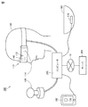
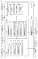
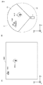
図1を参照して、HMD(Head Mount Display)システム100の構成について説明する。図1は、ある実施の形態に従うHMDシステム100の構成の概略を表す図である。ある局面において、HMDシステム100は、家庭用のシステムとしてあるいは業務用のシステムとして提供される。
[Configuration of HMD system]
A configuration of an HMD (Head Mount Display) system 100 will be described with reference to FIG. FIG. 1 is a diagram representing an outline of a configuration of an HMD system 100 according to an embodiment. In one aspect, the HMD system 100 is provided as a home system or a business system.

図1に示されるように、ある実施の形態に従うHMDシステム100は、HMD装置110と、HMDセンサ120と、ボード180と、コンピュータ200とを備える。HMD装置110は、モニタ112と、注視センサ140とを含む。ボード180は、傾きセ
ンサ170を含む。ある局面において、コンピュータ200は、ネットワーク19に接続可能であり、ネットワーク19に接続されているサーバ150と通信可能である。別の局面において、HMD装置110は、HMDセンサ120の代わりに、センサ114を含み得る。
As shown in FIG. 1, an HMD system 100 according to an embodiment includes an HMD device 110, an HMD sensor 120, a board 180, and a computer 200. The HMD device 110 includes a monitor 112 and a gaze sensor 140. The board 180 includes a tilt sensor 170. In one aspect, the computer 200 can be connected to the network 19 and can communicate with the server 150 connected to the network 19. In another aspect, the HMD device 110 may include a sensor 114 instead of the HMD sensor 120.

ある実施の形態に従うHMD装置110は、ユーザの頭部に装着され、動作中に仮想空間をユーザに提供し得る。より具体的には、HMD装置110は、右目用の画像および左目用の画像をモニタ112にそれぞれ表示する。ユーザの各目がそれぞれの画像を視認すると、ユーザは、両目の視差に基づき当該画像を3次元の画像として認識し得る。   The HMD device 110 according to an embodiment may be worn on the user's head and provide a virtual space to the user during operation. More specifically, the HMD device 110 displays a right-eye image and a left-eye image on the monitor 112, respectively. When each eye of the user visually recognizes each image, the user can recognize the image as a three-dimensional image based on the parallax of both eyes.

モニタ112は、例えば、非透過型の表示装置として実現される。ある局面において、モニタ112は、ユーザの両目の前方に位置するようにHMD装置110の本体に配置されている。したがって、ユーザは、モニタ112に表示される3次元画像を視認すると、仮想空間に没入することができる。ある実施の形態において、仮想空間は、例えば、背景、ユーザが操作可能なオブジェクト、ユーザが選択可能なメニューの画像を含む。ある実施の形態において、モニタ112は、所謂スマートフォンその他の情報表示端末が備える液晶モニタまたは有機EL(Electro Luminescence)モニタとして実現され得る。   The monitor 112 is realized as, for example, a non-transmissive display device. In one aspect, the monitor 112 is disposed on the main body of the HMD device 110 so as to be positioned in front of both eyes of the user. Therefore, when the user visually recognizes the three-dimensional image displayed on the monitor 112, the user can be immersed in the virtual space. In one embodiment, the virtual space includes, for example, a background, an object that can be operated by the user, and an image of a menu that can be selected by the user. In an embodiment, the monitor 112 may be realized as a liquid crystal monitor or an organic EL (Electro Luminescence) monitor provided in a so-called smartphone or other information display terminal.

ある局面において、モニタ112は、右目用の画像を表示するためのサブモニタと、左目用の画像を表示するためのサブモニタとを含み得る。別の局面において、モニタ112は、右目用の画像と左目用の画像とを一体として表示する構成であってもよい。この場合、モニタ112は、高速シャッタを含む。高速シャッタは、画像がいずれか一方の目にのみ認識されるように、右目用の画像と左目用の画像とを交互に表示可能に作動する。   In one aspect, the monitor 112 may include a sub-monitor for displaying an image for the right eye and a sub-monitor for displaying an image for the left eye. In another aspect, the monitor 112 may be configured to display a right-eye image and a left-eye image together. In this case, the monitor 112 includes a high-speed shutter. The high-speed shutter operates so that an image for the right eye and an image for the left eye can be displayed alternately so that the image is recognized only by one of the eyes.

HMDセンサ120は、複数の光源(図示しない)を含む。各光源は例えば、赤外線を発するLEDにより実現される。HMDセンサ120は、HMD装置110の動きを検出するためのポジショントラッキング機能を有する。HMDセンサ120は、この機能を用いて、現実空間内におけるHMD装置110の位置および傾きを検出する。   The HMD sensor 120 includes a plurality of light sources (not shown). Each light source is realized by, for example, an LED that emits infrared rays. The HMD sensor 120 has a position tracking function for detecting the movement of the HMD device 110. The HMD sensor 120 detects the position and inclination of the HMD device 110 in the real space using this function.

なお、別の局面において、HMDセンサ120は、カメラにより実現されてもよい。この場合、HMDセンサ120は、カメラから出力されるHMD装置110の画像情報を用いて、画像解析処理を実行することにより、HMD装置110の位置および傾きを検出することができる。   In another aspect, HMD sensor 120 may be realized by a camera. In this case, the HMD sensor 120 can detect the position and inclination of the HMD device 110 by executing image analysis processing using image information of the HMD device 110 output from the camera.

別の局面において、HMD装置110は、位置検出器として、HMDセンサ120の代わりに、センサ114を備えてもよい。HMD装置110は、センサ114を用いて、HMD装置110自身の位置および傾きを検出し得る。例えば、センサ114が角速度センサ、地磁気センサ、加速度センサ、あるいはジャイロセンサ等である場合、HMD装置110は、HMDセンサ120の代わりに、これらの各センサのいずれかを用いて、自身の位置および傾きを検出し得る。一例として、センサ114が角速度センサである場合、角速度センサは、現実空間におけるHMD装置110の3軸周りの角速度を経時的に検出する。HMD装置110は、各角速度に基づいて、HMD装置110の3軸周りの角度の時間的変化を算出し、さらに、角度の時間的変化に基づいて、HMD装置110の傾きを算出する。   In another aspect, the HMD device 110 may include a sensor 114 instead of the HMD sensor 120 as a position detector. The HMD device 110 can detect the position and inclination of the HMD device 110 itself using the sensor 114. For example, when the sensor 114 is an angular velocity sensor, a geomagnetic sensor, an acceleration sensor, a gyro sensor, or the like, the HMD device 110 uses any one of these sensors instead of the HMD sensor 120 to detect its position and inclination. Can be detected. As an example, when the sensor 114 is an angular velocity sensor, the angular velocity sensor detects angular velocities around the three axes of the HMD device 110 in real space over time. The HMD device 110 calculates the temporal change of the angle around the three axes of the HMD device 110 based on each angular velocity, and further calculates the inclination of the HMD device 110 based on the temporal change of the angle.

注視センサ140は、ユーザ190の右目および左目の視線が向けられる方向(視線方向)を検出する。当該方向の検出は、例えば、公知のアイトラッキング機能によって実現される。注視センサ140は、当該アイトラッキング機能を有するセンサにより実現される。ある局面において、注視センサ140は、右目用のセンサおよび左目用のセンサを含むことが好ましい。注視センサ140は、例えば、ユーザ190の右目および左目に赤外
光を照射するとともに、照射光に対する角膜および虹彩からの反射光を受けることにより各眼球の回転角を検出するセンサであってもよい。注視センサ140は、検出した各回転角に基づいて、ユーザ190の視線方向を検知することができる。
The gaze sensor 140 detects a direction (gaze direction) in which the gaze of the right eye and the left eye of the user 190 is directed. The detection of the direction is realized by, for example, a known eye tracking function. The gaze sensor 140 is realized by a sensor having the eye tracking function. In one aspect, the gaze sensor 140 preferably includes a right eye sensor and a left eye sensor. The gaze sensor 140 may be, for example, a sensor that irradiates the right eye and the left eye of the user 190 with infrared light and detects the rotation angle of each eyeball by receiving reflected light from the cornea and iris with respect to the irradiated light. . The gaze sensor 140 can detect the line-of-sight direction of the user 190 based on each detected rotation angle.

サーバ150は、コンピュータ200にプログラムを送信し得る。別の局面において、サーバ150は、他のユーザによって使用されるHMD装置に仮想現実を提供するための他のコンピュータ200と通信し得る。例えば、アミューズメント施設において、複数のユーザが参加型のゲームを行なう場合、各コンピュータ200は、各ユーザの動作に基づく信号を他のコンピュータ200と通信して、同じ仮想空間において複数のユーザが共通のゲームを楽しむことを可能にする。   Server 150 may send a program to computer 200. In another aspect, the server 150 may communicate with other computers 200 for providing virtual reality to HMD devices used by other users. For example, when a plurality of users play a participatory game in an amusement facility, each computer 200 communicates a signal based on each user's operation with another computer 200, and a plurality of users are common in the same virtual space. Allows you to enjoy the game.

ある実施の形態に従うと、HMDシステム100は、コントローラ160をさらに備えてもよい。コントローラ160はモーションセンサ130を含み得る。   According to an embodiment, the HMD system 100 may further include a controller 160. The controller 160 can include a motion sensor 130.

コントローラ160は、ユーザ190からコンピュータ200への命令の入力を受け付ける。ある局面において、コントローラ160は、ユーザ190によって把持可能に構成される。別の局面において、コントローラ160は、ユーザ190の身体あるいは衣類の一部に装着可能に構成される。別の局面において、コントローラ160は、コンピュータ200から送られる信号に基づいて、振動、音、光のうちの少なくともいずれかを出力するように構成されてもよい。   The controller 160 receives input of commands from the user 190 to the computer 200. In one aspect, the controller 160 is configured to be gripped by the user 190. In another aspect, the controller 160 is configured to be attachable to the body of the user 190 or a part of clothing. In another aspect, the controller 160 may be configured to output at least one of vibration, sound, and light based on a signal sent from the computer 200.

モーションセンサ130は、ある局面において、ユーザの手に取り付けられて、ユーザの手の動きを検出する。例えば、モーションセンサ130は、手の回転速度、回転数等を検出する。検出された信号は、コンピュータ200に送られる。モーションセンサ130は、例えば、手袋型のコントローラ160に設けられている。ある実施の形態において、現実空間における安全のため、コントローラ160は、手袋型のようにユーザ190の手に装着されることにより容易に飛んで行かないものに装着されるのが望ましい。別の局面において、ユーザ190に装着されないセンサがユーザ190の手の動きを検出してもよい。例えば、ユーザ190を撮影するカメラの信号が、ユーザ190の動作を表わす信号として、コンピュータ200に入力されてもよい。モーションセンサ130とコンピュータ200とは、有線により、または無線により互いに接続される。無線の場合、通信形態は特に限られず、例えば、Bluetooth(登録商標)その他の公知の通信手法が用いられる。   In one aspect, the motion sensor 130 is attached to the user's hand and detects the movement of the user's hand. For example, the motion sensor 130 detects the rotation speed, rotation speed, etc. of the hand. The detected signal is sent to the computer 200. The motion sensor 130 is provided in a glove-type controller 160, for example. In some embodiments, for safety in real space, it is desirable that the controller 160 be mounted on something that does not fly easily by being mounted on the hand of the user 190, such as a glove shape. In another aspect, a sensor that is not worn by the user 190 may detect the hand movement of the user 190. For example, a signal from a camera that captures the user 190 may be input to the computer 200 as a signal representing the operation of the user 190. The motion sensor 130 and the computer 200 are connected to each other by wire or wirelessly. In the case of wireless communication, the communication form is not particularly limited, and for example, Bluetooth (registered trademark) or other known communication methods are used.

傾きセンサ170は、例えば、加速度センサ、タッチセンサ等によって実現される。ある実施の形態において、ボード180のように底部が球面状である部材では、加速度センサが傾きセンサ170として使用される。ある実施の形態において、ボブスレーのように側壁を有する器具がユーザ190によって使用される場合には、加速度センサに加えて、あるいは加速度センサの代わりに、タッチセンサが傾きセンサとして左右の側壁に配置されてもよい。この場合、当該器具は、ユーザ190がタッチした側壁の方向に傾いていることが検知され得る。   The tilt sensor 170 is realized by, for example, an acceleration sensor, a touch sensor, or the like. In an embodiment, an acceleration sensor is used as the tilt sensor 170 for a member having a spherical bottom, such as the board 180. In an embodiment, when a device having a side wall such as a bobsled is used by the user 190, a touch sensor is arranged on the left and right side walls as a tilt sensor in addition to or instead of the acceleration sensor. May be. In this case, it can be detected that the instrument is tilted toward the side wall touched by the user 190.

ボード180は、上面に作用する荷重に応じて傾くように構成されている。例えば、ある局面において、ボード180の底面には、円弧状の傾きが形成されている。別の局面において、ボード180は、作用する荷重をボード180が設置される床に伝達するように配置された複数のばねその他の弾性部材を含む。   The board 180 is configured to incline according to the load acting on the upper surface. For example, in one aspect, an arcuate inclination is formed on the bottom surface of the board 180. In another aspect, the board 180 includes a plurality of springs or other elastic members arranged to transmit the acting load to the floor on which the board 180 is installed.

[ハードウェア構成]
図2を参照して、本実施の形態に係るコンピュータ200について説明する。図2は、一局面に従うコンピュータ200のハードウェア構成の一例を表すブロック図である。コ
ンピュータ200は、主たる構成要素として、プロセッサ10と、メモリ11と、ストレージ12と、入出力インターフェイス13と、通信インターフェイス14とを備える。各構成要素は、それぞれ、バス15に接続されている。
[Hardware configuration]
A computer 200 according to the present embodiment will be described with reference to FIG. FIG. 2 is a block diagram illustrating an example of a hardware configuration of computer 200 according to one aspect. The computer 200 includes a processor 10, a memory 11, a storage 12, an input / output interface 13, and a communication interface 14 as main components. Each component is connected to the bus 15.

プロセッサ10は、コンピュータ200に与えられる信号に基づいて、あるいは、予め定められた条件が成立したことに基づいて、メモリ11またはストレージ12に格納されているプログラムに含まれる一連の命令を実行する。ある局面において、プロセッサ10は、CPU(Central Processing Unit)、MPU(Micro Processor Unit)、FP
GA(Field-Programmable Gate Array)その他のデバイスとして実現される。
The processor 10 executes a series of instructions included in the program stored in the memory 11 or the storage 12 based on a signal given to the computer 200 or based on the establishment of a predetermined condition. In one aspect, the processor 10 includes a CPU (Central Processing Unit), an MPU (Micro Processor Unit), and an FP.
Realized as GA (Field-Programmable Gate Array) and other devices.

メモリ11は、プログラムおよびデータを一時的に保存する。プログラムは、例えば、ストレージ12からロードされる。データは、コンピュータ200に入力されたデータと、プロセッサ10によって生成されたデータとを含む。ある局面において、メモリ11は、RAM(Random Access Memory)その他の揮発メモリとして実現される。   The memory 11 temporarily stores programs and data. The program is loaded from the storage 12, for example. The data includes data input to the computer 200 and data generated by the processor 10. In one aspect, the memory 11 is realized as a RAM (Random Access Memory) or other volatile memory.

ストレージ12は、プログラムおよびデータを永続的に保持する。ストレージ12は、例えば、ROM(Read-Only Memory)、ハードディスク装置、フラッシュメモリ、その
他の不揮発記憶装置として実現される。ストレージ12に格納されるプログラムは、HMDシステム100において仮想空間を提供するためのプログラム、シミュレーションプログラム、ゲームプログラム、ユーザ認証プログラム、他のコンピュータ200との通信を実現するためのプログラムを含む。ストレージ12に格納されるデータは、仮想空間を規定するためのデータおよびオブジェクト等を含む。
The storage 12 holds programs and data permanently. The storage 12 is realized as, for example, a ROM (Read-Only Memory), a hard disk device, a flash memory, and other nonvolatile storage devices. The programs stored in the storage 12 include a program for providing a virtual space in the HMD system 100, a simulation program, a game program, a user authentication program, and a program for realizing communication with another computer 200. The data stored in the storage 12 includes data and objects for defining the virtual space.

なお、別の局面において、ストレージ12は、メモリカードのように着脱可能な記憶装置として実現されてもよい。さらに別の局面において、コンピュータ200に内蔵されたストレージ12の代わりに、外部の記憶装置に保存されているプログラムおよびデータを使用する構成が使用されてもよい。このような構成によれば、例えば、アミューズメント施設のように複数のHMDシステム100が使用される場面において、プログラムやデータの更新を一括して行なうことが可能になる。   In another aspect, the storage 12 may be realized as a removable storage device such as a memory card. In still another aspect, a configuration using a program and data stored in an external storage device may be used instead of the storage 12 built in the computer 200. According to such a configuration, for example, in a scene where a plurality of HMD systems 100 are used as in an amusement facility, it is possible to update programs and data collectively.

ある実施の形態において、入出力インターフェイス13は、HMD装置110、HMDセンサ120、モーションセンサ130、および傾きセンサ170との間で信号を通信する。ある局面において、入出力インターフェイス13は、USB(Universal Serial Bus)インターフェイス、DVI(Digital Visual Interface)、HDMI(登録商標)(High-Definition Multimedia Interface)その他の端子を用いて実現される。なお、入出力インターフェイス13は上述のものに限られない。   In one embodiment, the input / output interface 13 communicates signals between the HMD device 110, the HMD sensor 120, the motion sensor 130, and the tilt sensor 170. In one aspect, the input / output interface 13 is realized using a USB (Universal Serial Bus) interface, a DVI (Digital Visual Interface), an HDMI (registered trademark) (High-Definition Multimedia Interface), or other terminals. The input / output interface 13 is not limited to that described above.

ある実施の形態において、入出力インターフェイス13は、さらに、コントローラ160と通信し得る。例えば、入出力インターフェイス13は、モーションセンサ130から出力された信号の入力を受ける。別の局面において、入出力インターフェイス13は、プロセッサ10から出力された命令を、コントローラ160に送る。当該命令は、振動、音声出力、発光等をコントローラ160に指示する。コントローラ160は、当該命令を受信すると、その命令に応じて、振動、音声出力または発光のいずれかを実行する。   In certain embodiments, the input / output interface 13 may further communicate with the controller 160. For example, the input / output interface 13 receives a signal output from the motion sensor 130. In another aspect, the input / output interface 13 sends the instruction output from the processor 10 to the controller 160. The command instructs the controller 160 to vibrate, output sound, emit light, and the like. When the controller 160 receives the command, the controller 160 executes vibration, sound output, or light emission according to the command.

通信インターフェイス14は、ネットワーク19に接続されて、ネットワーク19に接続されている他のコンピュータ(例えば、サーバ150)と通信する。ある局面において、通信インターフェイス14は、例えば、LAN(Local Area Network)その他の有線通信インターフェイス、あるいは、WiFi(Wireless Fidelity)、Bluetooth(登録商標)、NFC(Near Field Communication)その他の無線通信インターフェイスとして実現される。なお、通信インターフェイス14は上述のものに限られない。   The communication interface 14 is connected to the network 19 and communicates with other computers (for example, the server 150) connected to the network 19. In one aspect, the communication interface 14 is realized as, for example, a local area network (LAN) or other wired communication interface, or a wireless communication interface such as WiFi (Wireless Fidelity), Bluetooth (registered trademark), NFC (Near Field Communication), or the like. Is done. The communication interface 14 is not limited to the above.

ある局面において、プロセッサ10は、ストレージ12に格納されている1つ以上のプログラムをメモリ11にロードし、当該プログラムに含まれる一連の命令を実行する。当該1つ以上のプログラムは、コンピュータ200のオペレーティングシステム、仮想空間を提供するためのアプリケーションプログラム、コントローラ160を用いて仮想空間で実行可能なゲームソフトウェア等を含み得る。プロセッサ10は、入出力インターフェイス13を介して、仮想空間を提供するための信号をHMD装置110に送る。HMD装置110は、その信号に基づいてモニタ112に映像を表示する。   In one aspect, the processor 10 loads one or more programs stored in the storage 12 into the memory 11 and executes a series of instructions included in the program. The one or more programs may include an operating system of the computer 200, an application program for providing a virtual space, game software that can be executed in the virtual space using the controller 160, and the like. The processor 10 sends a signal for providing a virtual space to the HMD device 110 via the input / output interface 13. The HMD device 110 displays an image on the monitor 112 based on the signal.

なお、図2に示される例では、コンピュータ200は、HMD装置110の外部に設けられる構成が示されているが、別の局面において、コンピュータ200は、HMD装置110に内蔵されてもよい。一例として、モニタ112を含む携帯型の情報通信端末(例えば、スマートフォン)がコンピュータ200として機能してもよい。   In the example illustrated in FIG. 2, the computer 200 is configured to be provided outside the HMD device 110. However, in another aspect, the computer 200 may be incorporated in the HMD device 110. As an example, a portable information communication terminal (for example, a smartphone) including the monitor 112 may function as the computer 200.

また、コンピュータ200は、複数のHMD装置110に共通して用いられる構成であってもよい。このような構成によれば、例えば、複数のユーザに同一の仮想空間を提供することもできるので、各ユーザは同一の仮想空間で他のユーザと同一のアプリケーションを楽しむことができる。   Further, the computer 200 may be configured to be used in common for the plurality of HMD devices 110. According to such a configuration, for example, the same virtual space can be provided to a plurality of users, so that each user can enjoy the same application as other users in the same virtual space.

ある実施の形態において、HMDシステム100では、グローバル座標系が予め設定されている。グローバル座標系は、現実空間における鉛直方向、鉛直方向に直交する水平方向、ならびに、鉛直方向および水平方向の双方に直交する前後方向にそれぞれ平行な、3つの基準方向(軸)を有する。本実施の形態では、グローバル座標系は視点座標系の一つである。そこで、グローバル座標系における水平方向、鉛直方向(上下方向)、および前後方向は、それぞれ、x軸、y軸、z軸と規定される。より具体的には、グローバル座標系において、x軸は現実空間の水平方向に平行である。y軸は、現実空間の鉛直方向に平行である。z軸は現実空間の前後方向に平行である。   In an embodiment, in the HMD system 100, a global coordinate system is set in advance. The global coordinate system has three reference directions (axes) parallel to the vertical direction in the real space, the horizontal direction orthogonal to the vertical direction, and the front-rear direction orthogonal to both the vertical direction and the horizontal direction. In the present embodiment, the global coordinate system is one of the viewpoint coordinate systems. Therefore, the horizontal direction, the vertical direction (vertical direction), and the front-rear direction in the global coordinate system are defined as an x-axis, a y-axis, and a z-axis, respectively. More specifically, in the global coordinate system, the x axis is parallel to the horizontal direction of the real space. The y axis is parallel to the vertical direction of the real space. The z axis is parallel to the front-rear direction of the real space.

ある局面において、HMDセンサ120は、赤外線センサを含む。赤外線センサが、HMD装置110の各光源から発せられた赤外線をそれぞれ検出すると、HMD装置110の存在を検出する。HMDセンサ120は、さらに、各点の値(グローバル座標系における各座標値)に基づいて、HMD装置110を装着したユーザ190の動きに応じた、現実空間内におけるHMD装置110の位置および傾きを検出する。より詳しくは、HMDセンサ120は、経時的に検出された各値を用いて、HMD装置110の位置および傾きの時間的変化を検出できる。   In one aspect, HMD sensor 120 includes an infrared sensor. When the infrared sensor detects each infrared ray emitted from each light source of the HMD device 110, the presence of the HMD device 110 is detected. The HMD sensor 120 further determines the position and inclination of the HMD device 110 in the real space according to the movement of the user 190 wearing the HMD device 110 based on the value of each point (each coordinate value in the global coordinate system). To detect. More specifically, the HMD sensor 120 can detect temporal changes in the position and tilt of the HMD device 110 using each value detected over time.

グローバル座標系は現実空間の座標系と平行である。したがって、HMDセンサ120によって検出されたHMD装置110の各傾きは、グローバル座標系におけるHMD装置110の3軸周りの各傾きに相当する。HMDセンサ120は、グローバル座標系におけるHMD装置110の傾きに基づき、uvw視野座標系をHMD装置110に設定する。HMD装置110に設定されるuvw視野座標系は、HMD装置110を装着したユーザ190が仮想空間において物体を見る際の視点座標系に対応する。   The global coordinate system is parallel to the real space coordinate system. Therefore, each inclination of the HMD device 110 detected by the HMD sensor 120 corresponds to each inclination around the three axes of the HMD device 110 in the global coordinate system. The HMD sensor 120 sets the uvw visual field coordinate system to the HMD device 110 based on the inclination of the HMD device 110 in the global coordinate system. The uvw visual field coordinate system set in the HMD device 110 corresponds to a viewpoint coordinate system when the user 190 wearing the HMD device 110 views an object in the virtual space.

[開示された実施の形態の構成の概要]
ある実施の形態に従うと、コンピュータがヘッドマウントディスプレイ装置に仮想空間を提供するための方法が提供される。この方法は、少なくとも1つのプロセッサが、仮想空間を定義するステップと、少なくとも1つのプロセッサが、当該ヘッドマウントディスプレイ装置のユーザが傾いている方向(例えば、左右または前後のいずれか)を検出するステップと、少なくとも1つのプロセッサが、ユーザ190が傾いている方向に基づいて当該仮想空間においてユーザ190に相当する仮想ユーザの移動方向を決定するステップ
と、少なくとも1つのプロセッサが、当該仮想空間における仮想ユーザの視界が、決定された仮想ユーザの移動方向に移動するように、当該ヘッドマウントディスプレイ装置に当該視界を表示させるステップとを含む。
[Outline of configuration of disclosed embodiment]
According to an embodiment, a method is provided for a computer to provide virtual space to a head mounted display device. In this method, at least one processor defines a virtual space, and at least one processor detects a direction in which the user of the head mounted display device is tilted (eg, either left or right or front and back). And at least one processor determines a moving direction of a virtual user corresponding to the user 190 in the virtual space based on a direction in which the user 190 is inclined, and the at least one processor is a virtual user in the virtual space. Displaying the field of view on the head-mounted display device so that the field of view moves in the determined moving direction of the virtual user.

ある実施の形態に従うと、当該移動方向を決定するステップは、ユーザ190の傾きが継続している時間に応じて、当該移動方向を決定することを含む。   According to an embodiment, the step of determining the direction of movement includes determining the direction of movement according to the time during which the user 190 is tilted.

ある実施の形態に従うと、当該移動方向を決定するステップは、ユーザ190の傾きの程度に応じて、当該移動方向を決定することを含む。   According to an embodiment, the step of determining the movement direction includes determining the movement direction according to the degree of inclination of the user 190.

ある実施の形態に従うと、当該方法は、少なくとも1つのプロセッサが、検出されたユーザ190の傾きに基づいて当該仮想空間における仮想ユーザの移動距離を決定するステップをさらに備える。当該視界を表示させるステップは、仮想ユーザの視界が当該移動方向に向かって当該移動距離だけ移動するように、当該視界を表示させることを含む。   According to an embodiment, the method further comprises the step of the at least one processor determining a moving distance of the virtual user in the virtual space based on the detected inclination of the user 190. The step of displaying the visual field includes displaying the visual field so that the visual field of the virtual user moves in the moving direction by the moving distance.

ある実施の形態に従う、コンピュータがヘッドマウントディスプレイ装置に仮想空間を提供するための方法は、少なくとも1つのプロセッサが、仮想空間を定義するステップと、少なくとも1つのプロセッサが、当該ヘッドマウントディスプレイ装置のユーザが傾いている方向を検出するステップと、少なくとも1つのプロセッサが、検出されたユーザ190の傾きに基づいて当該仮想空間における仮想ユーザの移動距離を決定するステップと、少なくとも1つのプロセッサが、当該仮想空間における仮想ユーザの視界が、決定された仮想ユーザの移動距離だけ移動するように、当該ヘッドマウントディスプレイ装置に当該視界を表示させるステップとを含む。   According to an embodiment, a method for a computer to provide virtual space to a head mounted display device includes: at least one processor defining the virtual space; and at least one processor being a user of the head mounted display device. Detecting the direction in which the virtual user is inclined, at least one processor determining a moving distance of the virtual user in the virtual space based on the detected inclination of the user 190, and at least one processor including the virtual Displaying the field of view on the head mounted display device so that the field of view of the virtual user in the space moves by the determined moving distance of the virtual user.

ある実施の形態に従うと、当該移動距離を決定するステップは、ユーザ190の傾きが継続している時間に応じて、当該移動距離を決定することを含む。   According to an embodiment, the step of determining the movement distance includes determining the movement distance according to a time during which the inclination of the user 190 continues.

ある実施の形態に従うと、当該移動距離を決定するステップは、ユーザ190の傾きの程度に応じて、当該移動距離を決定することを含む。   According to an embodiment, the step of determining the movement distance includes determining the movement distance according to the degree of inclination of the user 190.

ある実施の形態に従うと、ユーザ190が傾いている方向を検出するステップは、ユーザ190による体重移動を伴う動作または姿勢に基づく加速度を検出するステップを含む。   According to an embodiment, the step of detecting the direction in which the user 190 is tilted includes the step of detecting an acceleration based on an action or posture accompanied by weight shift by the user 190.

ある実施の形態に従うと、ユーザ190が傾いている方向を検出するステップは、ユーザ190から作用する荷重を検出することを含む。   According to an embodiment, detecting the direction in which the user 190 is tilted includes detecting a load acting from the user 190.

ある実施の形態に従うと、当該プロセッサは、仮想空間を定義し、当該ヘッドマウントディスプレイ装置のユーザが傾いている方向を検出し、検出された方向に基づいて当該仮想空間における仮想ユーザの移動方向を決定し、当該仮想空間における仮想ユーザの視界が、決定された仮想ユーザの移動方向に移動するように、当該ヘッドマウントディスプレイ装置に当該視界を表示させるように構成されている。   According to an embodiment, the processor defines a virtual space, detects a direction in which a user of the head mounted display device is tilted, and determines a moving direction of the virtual user in the virtual space based on the detected direction. The visual field of the virtual user in the virtual space is determined, and the visual field is displayed on the head mounted display device so that the virtual user's visual field moves in the determined moving direction of the virtual user.

ある実施の形態に従うと、当該プロセッサは、検出されたユーザ190の傾きに基づいて当該仮想空間における仮想ユーザの移動距離を決定するようにさらに構成されている。当該視界を表示させることは、仮想ユーザの視界が当該移動方向に向かって当該移動距離だけ移動するように、当該視界を表示させることを含む。   According to an embodiment, the processor is further configured to determine a moving distance of the virtual user in the virtual space based on the detected inclination of the user 190. Displaying the field of view includes displaying the field of view such that the field of view of the virtual user moves in the movement direction by the movement distance.

ある実施の形態に従うと、プロセッサは、仮想空間を定義し、当該ヘッドマウントディスプレイ装置のユーザが傾いている方向を検出し、検出された方向に基づいて当該仮想空
間における仮想ユーザの移動距離を決定し、当該仮想空間における仮想ユーザの視界が、決定された仮想ユーザの移動距離だけ移動するように、当該ヘッドマウントディスプレイ装置に当該視界を表示させるように構成されている。
According to an embodiment, the processor defines a virtual space, detects a direction in which a user of the head mounted display device is tilted, and determines a moving distance of the virtual user in the virtual space based on the detected direction. Then, the field of view of the virtual user in the virtual space is configured to display the field of view on the head mounted display device so as to move by the determined moving distance of the virtual user.

[uvw視野座標系]
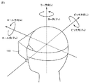
図3を参照して、uvw視野座標系について説明する。図3は、ある実施の形態に従うHMD装置110に設定されるuvw視野座標系を概念的に表す図である。HMDセンサ120は、HMD装置110の起動時に、グローバル座標系におけるHMD装置110の位置および傾きを検出する。プロセッサ10は、検出された値に基づいて、uvw視野座標系をHMD装置110に設定する。
[Uvw visual field coordinate system]
The uvw visual field coordinate system will be described with reference to FIG. FIG. 3 is a diagram conceptually showing a uvw visual field coordinate system set in HMD device 110 according to an embodiment. The HMD sensor 120 detects the position and inclination of the HMD device 110 in the global coordinate system when the HMD device 110 is activated. The processor 10 sets the uvw visual field coordinate system in the HMD device 110 based on the detected value.

図3に示されるように、HMD装置110は、HMD装置110を装着したユーザの頭部を中心(原点)とした3次元のuvw視野座標系を設定する。より具体的には、HMD装置110は、グローバル座標系を規定する水平方向、鉛直方向、および前後方向(x軸、y軸、z軸)を、グローバル座標系内においてHMD装置110の各軸周りの傾きだけ各軸周りにそれぞれ傾けることによって新たに得られる3つの方向を、HMD装置110におけるuvw視野座標系のピッチ方向(u軸)、ヨー方向(v軸)、およびロール方向(w軸)として設定する。   As shown in FIG. 3, the HMD device 110 sets a three-dimensional uvw visual field coordinate system with the head (origin) of the user wearing the HMD device 110 as the center (origin). More specifically, the HMD device 110 uses the horizontal direction, the vertical direction, and the front-rear direction (x axis, y axis, z axis) that define the global coordinate system around each axis of the HMD device 110 in the global coordinate system. The three new directions obtained by inclining around the respective axes by the inclination of the pitch are the pitch direction (u-axis), yaw direction (v-axis), and roll direction (w-axis) of the uvw visual field coordinate system in the HMD device 110. Set as.

ある局面において、HMD装置110を装着したユーザ190が直立し、かつ、正面を視認している場合、プロセッサ10は、グローバル座標系に平行なuvw視野座標系をHMD装置110に設定する。この場合、グローバル座標系における水平方向(x軸)、鉛直方向(y軸)、および前後方向(z軸)は、HMD装置110におけるuvw視野座標系のピッチ方向(u軸)、ヨー方向(v軸)、およびロール方向(w軸)に一致する。   In one aspect, when the user 190 wearing the HMD device 110 stands upright and is viewing the front, the processor 10 sets the uvw visual field coordinate system parallel to the global coordinate system in the HMD device 110. In this case, the horizontal direction (x-axis), vertical direction (y-axis), and front-rear direction (z-axis) in the global coordinate system are the pitch direction (u-axis) and yaw direction (v Axis) and the roll direction (w-axis).

uvw視野座標系がHMD装置110に設定された後、HMDセンサ120は、HMD装置110の動きに基づいて、設定されたuvw視野座標系におけるHMD装置110の傾き(傾きの変化量)を検出できる。この場合、HMDセンサ120は、HMD装置110の傾きとして、uvw視野座標系におけるHMD装置110のピッチ角(θu)、ヨー角(θv)、およびロール角(θw)をそれぞれ検出する。ピッチ角(θu)は、uvw視野座標系におけるピッチ方向周りのHMD装置110の傾き角度を表す。ヨー角(θv)は、uvw視野座標系におけるヨー方向周りのHMD装置110の傾き角度を表す。ロール角(θw)は、uvw視野座標系におけるロール方向周りのHMD装置110の傾き角度を表す。   After the uvw visual field coordinate system is set in the HMD device 110, the HMD sensor 120 can detect the inclination of the HMD device 110 in the set uvw visual field coordinate system based on the movement of the HMD device 110. . In this case, the HMD sensor 120 detects the pitch angle (θu), yaw angle (θv), and roll angle (θw) of the HMD device 110 in the uvw visual field coordinate system as the inclination of the HMD device 110. The pitch angle (θu) represents the tilt angle of the HMD device 110 around the pitch direction in the uvw visual field coordinate system. The yaw angle (θv) represents the tilt angle of the HMD device 110 around the yaw direction in the uvw visual field coordinate system. The roll angle (θw) represents the tilt angle of the HMD device 110 around the roll direction in the uvw visual field coordinate system.

HMDセンサ120は、検出されたHMD装置110の傾き角度に基づいて、HMD装置110が動いた後のHMD装置110におけるuvw視野座標系を、HMD装置110に設定する。HMD装置110と、HMD装置110のuvw視野座標系との関係は、HMD装置110の位置および傾きに関わらず、常に一定である。HMD装置110の位置および傾きが変わると、当該位置および傾きの変化に連動して、グローバル座標系におけるHMD装置110のuvw視野座標系の位置および傾きが変化する。   Based on the detected tilt angle of the HMD device 110, the HMD sensor 120 sets the uvw visual field coordinate system in the HMD device 110 after the HMD device 110 has moved to the HMD device 110. The relationship between the HMD device 110 and the uvw visual field coordinate system of the HMD device 110 is always constant regardless of the position and inclination of the HMD device 110. When the position and inclination of the HMD device 110 change, the position and inclination of the uvw visual field coordinate system of the HMD device 110 in the global coordinate system change in conjunction with the change of the position and inclination.

ある局面において、HMDセンサ120は、赤外線センサからの出力に基づいて取得される赤外線の光強度および複数の点間の相対的な位置関係(例えば、各点間の距離など)に基づいて、HMD装置110の現実空間内における位置を、HMDセンサ120に対する相対位置として特定してもよい。また、プロセッサ10は、特定された相対位置に基づいて、現実空間内(グローバル座標系)におけるHMD装置110のuvw視野座標系の原点を決定してもよい。   In one aspect, the HMD sensor 120 is based on the infrared light intensity acquired based on the output from the infrared sensor and the relative positional relationship between a plurality of points (for example, the distance between the points). The position of the device 110 in the real space may be specified as a relative position with respect to the HMD sensor 120. Further, the processor 10 may determine the origin of the uvw visual field coordinate system of the HMD device 110 in the real space (global coordinate system) based on the specified relative position.

[仮想空間]
図4を参照して、仮想空間についてさらに説明する。図4は、ある実施の形態に従う仮想空間2を表現する一態様を概念的に表す図である。仮想空間2は、中心21の360度方向の全体を覆う全天球状の構造を有する。図4では、説明を複雑にしないために、仮想空間2のうちの上半分の天球が例示されている。仮想空間2では各メッシュが規定される。各メッシュの位置は、仮想空間2に規定されるXYZ座標系における座標値として予め規定されている。コンピュータ200は、仮想空間2に展開可能なコンテンツ(静止画、動画等)を構成する各部分画像を、仮想空間2において対応する各メッシュにそれぞれ対応付けて、ユーザによって視認可能な仮想空間画像22が展開される仮想空間2をユーザに提供する。
[Virtual space]
The virtual space will be further described with reference to FIG. FIG. 4 is a diagram conceptually showing one aspect of expressing virtual space 2 according to an embodiment. The virtual space 2 has a spherical structure that covers the entire 360 ° direction of the center 21. In FIG. 4, the upper half of the celestial sphere in the virtual space 2 is illustrated in order not to complicate the description. In the virtual space 2, each mesh is defined. The position of each mesh is defined in advance as coordinate values in the XYZ coordinate system defined in the virtual space 2. The computer 200 associates each partial image constituting content (still image, moving image, etc.) that can be developed in the virtual space 2 with each corresponding mesh in the virtual space 2, and the virtual space image 22 that can be visually recognized by the user. Is provided to the user.

ある局面において、仮想空間2では、中心21を原点とするXYZ座標系が規定される。XYZ座標系は、例えば、グローバル座標系に平行である。XYZ座標系は視点座標系の一種であるため、XYZ座標系における水平方向、鉛直方向(上下方向)、および前後方向は、それぞれX軸、Y軸、Z軸として規定される。したがって、XYZ座標系のX軸(水平方向)がグローバル座標系のx軸と平行であり、XYZ座標系のY軸(鉛直方向)がグローバル座標系のy軸と平行であり、XYZ座標系のZ軸(前後方向)がグローバル座標系のz軸と平行である。   In one aspect, the virtual space 2 defines an XYZ coordinate system with the center 21 as the origin. The XYZ coordinate system is, for example, parallel to the global coordinate system. Since the XYZ coordinate system is a kind of viewpoint coordinate system, the horizontal direction, vertical direction (vertical direction), and front-rear direction in the XYZ coordinate system are defined as an X axis, a Y axis, and a Z axis, respectively. Therefore, the X axis (horizontal direction) of the XYZ coordinate system is parallel to the x axis of the global coordinate system, the Y axis (vertical direction) of the XYZ coordinate system is parallel to the y axis of the global coordinate system, and The Z axis (front-rear direction) is parallel to the z axis of the global coordinate system.

HMD装置110の起動時、すなわちHMD装置110の初期状態において、仮想カメラ1が、仮想空間2の中心21に配置される。仮想カメラ1は、現実空間におけるHMD装置110の動きに連動して、仮想空間2を同様に移動する。これにより、現実空間におけるHMD装置110の位置および向きの変化が、仮想空間2において同様に再現される。   When the HMD device 110 is activated, that is, in the initial state of the HMD device 110, the virtual camera 1 is disposed at the center 21 of the virtual space 2. The virtual camera 1 similarly moves in the virtual space 2 in conjunction with the movement of the HMD device 110 in the real space. Thereby, changes in the position and orientation of the HMD device 110 in the real space are similarly reproduced in the virtual space 2.

仮想カメラ1には、HMD装置110の場合と同様に、uvw視野座標系が規定される。仮想空間2における仮想カメラのuvw視野座標系は、現実空間(グローバル座標系)におけるHMD装置110のuvw視野座標系に連動するように規定されている。したがって、HMD装置110の傾きが変化すると、それに応じて、仮想カメラ1の傾きも変化する。また、仮想カメラ1は、HMD装置110を装着したユーザの現実空間における移動に連動して、仮想空間2において移動することもできる。   As in the case of the HMD device 110, the uvw visual field coordinate system is defined for the virtual camera 1. The uvw visual field coordinate system of the virtual camera in the virtual space 2 is defined so as to be linked to the uvw visual field coordinate system of the HMD device 110 in the real space (global coordinate system). Therefore, when the inclination of the HMD device 110 changes, the inclination of the virtual camera 1 also changes accordingly. The virtual camera 1 can also move in the virtual space 2 in conjunction with the movement of the user wearing the HMD device 110 in the real space.

仮想カメラ1の向きは、仮想カメラ1の位置および傾きに応じて決まるので、ユーザが仮想空間画像22を視認する際に基準となる視線(基準視線5)は、仮想カメラ1の向きに応じて決まる。コンピュータ200のプロセッサ10は、基準視線5に基づいて、仮想空間2における視界領域23を規定する。視界領域23は、仮想空間2のうち、HMD装置110を装着したユーザの視界に対応する。   Since the orientation of the virtual camera 1 is determined according to the position and inclination of the virtual camera 1, the reference line of sight (reference line of sight 5) when the user visually recognizes the virtual space image 22 depends on the orientation of the virtual camera 1. Determined. The processor 10 of the computer 200 defines the visual field region 23 in the virtual space 2 based on the reference line of sight 5. The view area 23 corresponds to the view of the user wearing the HMD device 110 in the virtual space 2.

注視センサ140によって検出されるユーザ190の視線方向は、ユーザ190が物体を視認する際の視点座標系における方向である。HMD装置110のuvw視野座標系は、ユーザ190がモニタ112を視認する際の視点座標系に等しい。また、仮想カメラ1のuvw視野座標系は、HMD装置110のuvw視野座標系に連動している。したがって、ある局面に従うHMDシステム100は、注視センサ140によって検出されたユーザ190の視線方向を、仮想カメラ1のuvw視野座標系におけるユーザの視線方向とみなすことができる。   The gaze direction of the user 190 detected by the gaze sensor 140 is a direction in the viewpoint coordinate system when the user 190 visually recognizes the object. The uvw visual field coordinate system of the HMD device 110 is equal to the viewpoint coordinate system when the user 190 visually recognizes the monitor 112. The uvw visual field coordinate system of the virtual camera 1 is linked to the uvw visual field coordinate system of the HMD device 110. Therefore, the HMD system 100 according to a certain aspect can regard the line-of-sight direction of the user 190 detected by the gaze sensor 140 as the line-of-sight direction of the user in the uvw visual field coordinate system of the virtual camera 1.

[ユーザの視線]
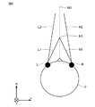
図5を参照して、ユーザの視線方向の決定について説明する。図5は、ある実施の形態に従うHMD装置110を装着するユーザ190の頭部を上から表した図である。
[User's line of sight]
With reference to FIG. 5, determination of the user's line-of-sight direction will be described. FIG. 5 is a diagram showing the head of user 190 wearing HMD device 110 according to an embodiment from above.

ある局面において、注視センサ140は、ユーザ190の右目および左目の各視線を検
出する。ある局面において、ユーザ190が近くを見ている場合、注視センサ140は、視線R1およびL1を検出する。別の局面において、ユーザ190が遠くを見ている場合、注視センサ140は、視線R2およびL2を検出する。この場合、ロール方向wに対して視線R2およびL2がなす角度は、ロール方向wに対して視線R1およびL1がなす角度よりも小さい。注視センサ140は、検出結果をコンピュータ200に送信する。
In one aspect, gaze sensor 140 detects each line of sight of user 190's right eye and left eye. In a certain aspect, when the user 190 is looking near, the gaze sensor 140 detects the lines of sight R1 and L1. In another aspect, when the user 190 is looking far away, the gaze sensor 140 detects the lines of sight R2 and L2. In this case, the angle formed by the lines of sight R2 and L2 with respect to the roll direction w is smaller than the angle formed by the lines of sight R1 and L1 with respect to the roll direction w. The gaze sensor 140 transmits the detection result to the computer 200.

コンピュータ200が、視線の検出結果として、視線R1およびL1の検出値を注視センサ140から受信した場合には、その検出値に基づいて、視線R1およびL1の交点である注視点N1を特定する。一方、コンピュータ200は、視線R2およびL2の検出値を注視センサ140から受信した場合には、視線R2およびL2の交点を注視点として特定する。コンピュータ200は、特定した注視点N1の位置に基づき、ユーザ190の視線方向N0を特定する。コンピュータ200は、例えば、ユーザ190の右目Rと左目Lとを結ぶ直線の中点と、注視点N1とを通る直線の延びる方向を、視線方向N0として検出する。視線方向N0は、ユーザ190が両目により実際に視線を向けている方向である。また、視線方向N0は、視界領域23に対してユーザ190が実際に視線を向けている方向に相当する。   When the computer 200 receives the detection values of the lines of sight R1 and L1 from the gaze sensor 140 as the line-of-sight detection result, the computer 200 identifies the point of sight N1 that is the intersection of the lines of sight R1 and L1 based on the detection value. On the other hand, when the detected values of the lines of sight R2 and L2 are received from the gaze sensor 140, the computer 200 specifies the intersection of the lines of sight R2 and L2 as the point of sight. The computer 200 specifies the line-of-sight direction N0 of the user 190 based on the specified position of the gazing point N1. For example, the computer 200 detects the direction in which the straight line passing through the midpoint of the straight line connecting the right eye R and the left eye L of the user 190 and the gazing point N1 extends as the line-of-sight direction N0. The line-of-sight direction N0 is a direction in which the user 190 is actually pointing the line of sight with both eyes. The line-of-sight direction N0 corresponds to the direction in which the user 190 actually directs his / her line of sight with respect to the field-of-view area 23.

別の局面において、HMDシステム100は、HMDシステム100を構成するいずれかのパーツに、マイクおよびスピーカを備えてもよい。ユーザは、マイクに発話することにより、仮想空間2に対して、音声による指示を与えることができる。   In another aspect, the HMD system 100 may include a microphone and a speaker in any part constituting the HMD system 100. The user can give a voice instruction to the virtual space 2 by speaking to the microphone.

また、別の局面において、HMDシステム100は、テレビジョン放送受信チューナを備えてもよい。このような構成によれば、HMDシステム100は、仮想空間2においてテレビ番組を表示することができる。   In another aspect, HMD system 100 may include a television broadcast receiving tuner. According to such a configuration, the HMD system 100 can display a television program in the virtual space 2.

さらに別の局面において、HMDシステム100は、インターネットに接続するための通信回路、あるいは、電話回線に接続するための通話機能を備えていてもよい。   In still another aspect, the HMD system 100 may include a communication circuit for connecting to the Internet or a call function for connecting to a telephone line.

[視界領域]
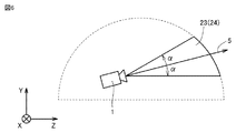
図6および図7を参照して、視界領域23について説明する。図6は、仮想空間2において視界領域23をX方向から見たYZ断面を表す図である。図7は、仮想空間2において視界領域23をY方向から見たXZ断面を表す図である。
[Visibility area]
With reference to FIGS. 6 and 7, the visual field region 23 will be described. FIG. 6 is a diagram illustrating a YZ cross section of the visual field region 23 viewed from the X direction in the virtual space 2. FIG. 7 is a diagram illustrating an XZ cross section of the visual field region 23 viewed from the Y direction in the virtual space 2.

図6に示されるように、YZ断面における視界領域23は、領域24を含む。領域24は、仮想カメラ1の基準視線5と仮想空間2のYZ断面とによって定義される。プロセッサ10は、仮想空間おける基準視線5を中心として極角αを含む範囲を、領域24として規定する。   As shown in FIG. 6, the visual field region 23 in the YZ cross section includes a region 24. The region 24 is defined by the reference line of sight 5 of the virtual camera 1 and the YZ cross section of the virtual space 2. The processor 10 defines a range including the polar angle α around the reference line of sight 5 in the virtual space as the region 24.

図7に示されるように、XZ断面における視界領域23は、領域25を含む。領域25は、基準視線5と仮想空間2のXZ断面とによって定義される。プロセッサ10は、仮想空間2における基準視線5を中心とした方位角βを含む範囲を、領域25として規定する。   As shown in FIG. 7, the visual field region 23 in the XZ cross section includes a region 25. The region 25 is defined by the reference line of sight 5 and the XZ cross section of the virtual space 2. The processor 10 defines a range including the azimuth angle β around the reference line of sight 5 in the virtual space 2 as a region 25.

ある局面において、HMDシステム100は、コンピュータ200からの信号に基づいて、視界画像26をモニタ112に表示させることにより、ユーザ190に仮想空間を提供する。視界画像26は、仮想空間画像22のうち視界領域23に重畳する部分に相当する。ユーザ190が、頭に装着したHMD装置110を動かすと、その動きに連動して仮想カメラ1も動く。その結果、仮想空間2における視界領域23の位置が変化する。これにより、モニタ112に表示される視界画像26は、仮想空間画像22のうち、仮想空間2においてユーザが向いた方向の視界領域23に重畳する画像に更新される。ユーザは、
仮想空間2における所望の方向を視認することができる。
In one aspect, the HMD system 100 provides the virtual space to the user 190 by displaying the view image 26 on the monitor 112 based on a signal from the computer 200. The view image 26 corresponds to a portion of the virtual space image 22 that is superimposed on the view region 23. When the user 190 moves the HMD device 110 worn on the head, the virtual camera 1 also moves in conjunction with the movement. As a result, the position of the visual field area 23 in the virtual space 2 changes. As a result, the view image 26 displayed on the monitor 112 is updated to an image that is superimposed on the view region 23 in the direction in which the user faces in the virtual space 2 in the virtual space image 22. The user
A desired direction in the virtual space 2 can be visually recognized.

ユーザ190は、HMD装置110を装着している間、現実世界を視認することなく、仮想空間2に展開される仮想空間画像22のみを視認できる。そのため、HMDシステム100は、仮想空間2への高い没入感覚をユーザに与えることができる。   The user 190 can visually recognize only the virtual space image 22 developed in the virtual space 2 without visually recognizing the real world while wearing the HMD device 110. Therefore, the HMD system 100 can give the user a high sense of immersion in the virtual space 2.

ある局面において、プロセッサ10は、HMD装置110を装着したユーザ190の現実空間における移動に連動して、仮想空間2において仮想カメラ1を移動し得る。この場合、プロセッサ10は、仮想空間2における仮想カメラ1の位置および向きに基づいて、HMD装置110のモニタ112に投影される画像領域(すなわち、仮想空間2における視界領域23)を特定する。   In one aspect, the processor 10 can move the virtual camera 1 in the virtual space 2 in conjunction with movement of the user 190 wearing the HMD device 110 in real space. In this case, the processor 10 specifies an image region (that is, the visual field region 23 in the virtual space 2) projected on the monitor 112 of the HMD device 110 based on the position and orientation of the virtual camera 1 in the virtual space 2.

ある実施の形態に従うと、仮想カメラ1は、二つの仮想カメラ、すなわち、右目用の画像を提供するための仮想カメラと、左目用の画像を提供するための仮想カメラとを含むことが望ましい。また、ユーザ190が3次元の仮想空間2を認識できるように、適切な視差が、二つの仮想カメラに設定されていることが好ましい。本実施の形態においては、仮想カメラ1が二つの仮想カメラを含み、二つの仮想カメラのロール方向が合成されることによって生成されるロール方向(w)がHMD装置110のロール方向(w)に適合されるように構成されているものとして、本開示に係る技術思想を例示する。   According to an embodiment, the virtual camera 1 preferably includes two virtual cameras, that is, a virtual camera for providing an image for the right eye and a virtual camera for providing an image for the left eye. Moreover, it is preferable that appropriate parallax is set in the two virtual cameras so that the user 190 can recognize the three-dimensional virtual space 2. In the present embodiment, the virtual camera 1 includes two virtual cameras, and the roll direction (w) generated by combining the roll directions of the two virtual cameras is the roll direction (w) of the HMD device 110. The technical idea concerning this indication is illustrated as what is constituted so that it may be adapted.

[HMD装置の制御装置]
図8を参照して、HMD装置110の制御装置について説明する。ある実施の形態において、制御装置は周知の構成を有するコンピュータ200によって実現される。図8は、ある実施の形態に従うコンピュータ200をモジュール構成として表わすブロック図である。
[Control device for HMD device]
A control device of the HMD device 110 will be described with reference to FIG. In one embodiment, the control device is realized by a computer 200 having a known configuration. FIG. 8 is a block diagram representing a computer 200 according to an embodiment as a module configuration.

図8に示されるように、コンピュータ200は、表示制御モジュール220と、仮想空間制御モジュール230と、メモリモジュール240と、通信制御モジュール250とを備える。表示制御モジュール220は、サブモジュールとして、仮想カメラ制御モジュール221と、視界領域決定モジュール222と、視界画像生成モジュール223と、基準視線特定モジュール224とを含む。仮想空間制御モジュール230は、サブモジュールとして、仮想空間定義モジュール231と、仮想オブジェクト生成モジュール232と、物体制御モジュール233と、移動方向決定モジュール234と、移動距離決定モジュール235とを含む。   As shown in FIG. 8, the computer 200 includes a display control module 220, a virtual space control module 230, a memory module 240, and a communication control module 250. The display control module 220 includes a virtual camera control module 221, a visual field region determination module 222, a visual field image generation module 223, and a reference visual line identification module 224 as submodules. The virtual space control module 230 includes a virtual space definition module 231, a virtual object generation module 232, an object control module 233, a movement direction determination module 234, and a movement distance determination module 235 as submodules.

ある実施の形態において、表示制御モジュール220と仮想空間制御モジュール230とは、プロセッサ10によって実現される。別の実施の形態において、複数のプロセッサ10が表示制御モジュール220と仮想空間制御モジュール230として作動してもよい。メモリモジュール240は、メモリ11またはストレージ12によって実現される。通信制御モジュール250は、通信インターフェイス14によって実現される。   In an embodiment, the display control module 220 and the virtual space control module 230 are realized by the processor 10. In another embodiment, multiple processors 10 may operate as the display control module 220 and the virtual space control module 230. The memory module 240 is realized by the memory 11 or the storage 12. The communication control module 250 is realized by the communication interface 14.

ある局面において、表示制御モジュール220は、HMD装置110のモニタ112における画像表示を制御する。仮想カメラ制御モジュール221は、仮想空間2に仮想カメラ1を配置し、仮想カメラ1の挙動、向き等を制御する。視界領域決定モジュール222は、視界領域23を規定する。視界画像生成モジュール223は、決定された視界領域23に基づいて、モニタ112に表示される視界画像26を生成する。   In one aspect, the display control module 220 controls image display on the monitor 112 of the HMD device 110. The virtual camera control module 221 arranges the virtual camera 1 in the virtual space 2 and controls the behavior, orientation, and the like of the virtual camera 1. The view area determination module 222 defines the view area 23. The view image generation module 223 generates a view image 26 to be displayed on the monitor 112 based on the determined view area 23.

基準視線特定モジュール224は、注視センサ140からの信号に基づいて、ユーザ190の視線を特定する。   The reference line-of-sight identifying module 224 identifies the line of sight of the user 190 based on the signal from the gaze sensor 140.

仮想空間制御モジュール230は、ユーザ190に提供される仮想空間2を制御する。仮想空間定義モジュール231は、仮想空間2を表わす仮想空間データを生成することにより、HMDシステム100における仮想空間2を規定する。   The virtual space control module 230 controls the virtual space 2 provided to the user 190. The virtual space definition module 231 defines the virtual space 2 in the HMD system 100 by generating virtual space data representing the virtual space 2.

仮想オブジェクト生成モジュール232は、仮想空間2に表示される対象物を生成する。対象物は、例えば、ゲームのストーリーの進行に従って表示される森、山その他を含む風景、動物等を含む。   The virtual object generation module 232 generates an object displayed in the virtual space 2. The object includes, for example, a forest, a mountainous landscape, an animal, and the like displayed according to the progress of the game story.

物体制御モジュール233は、仮想空間2においてユーザが保持する物体の動作を制御する。当該物体は、例えば、現実空間におけるユーザ190の動作に連動して、仮想空間2において表示される仮想ユーザが乗るための台、乗り物等を含み得る。ある実施の形態に従う乗り物は、例えば、そり、スキー、スノーボード、船舶その他の仮想ユーザの乗り物であって、荷重に応じて移動方向および移動速度の少なくともいずれか一方が変化する乗り物として実現される。   The object control module 233 controls the operation of the object held by the user in the virtual space 2. The object may include, for example, a platform for a virtual user displayed in the virtual space 2 or a vehicle in conjunction with the operation of the user 190 in the real space. The vehicle according to an embodiment is, for example, a vehicle of a sled, ski, snowboard, ship, or other virtual user, and is realized as a vehicle that changes at least one of a moving direction and a moving speed according to a load.

移動方向決定モジュール234は、傾きセンサ170からの出力に基づいて、仮想空間2における仮想ユーザの移動方向を決定する。ある実施の形態に従うと、移動方向決定モジュール234は、傾きセンサ170から出力される信号に基づいてユーザ190による荷重が作用する方向を検知し、当該方向を仮想ユーザが移動するべき方向として決定する。   The movement direction determination module 234 determines the movement direction of the virtual user in the virtual space 2 based on the output from the inclination sensor 170. According to an embodiment, the movement direction determination module 234 detects a direction in which a load applied by the user 190 acts based on a signal output from the tilt sensor 170, and determines the direction as a direction in which the virtual user should move. .

移動距離決定モジュール235は、傾きセンサ170からの出力に基づいて、仮想ユーザの移動距離を決定する。例えば、水平状態にあったボード180が傾いた場合に、移動距離決定モジュール235は、傾斜角度に応じた移動距離を決定する。ある局面において、移動距離決定モジュール235は、プロセッサ10が実行しているプログラムにおいて予め規定された傾斜角度一度当たりの仮想移動距離と、当該傾斜角度とに基づいて、仮想ユーザの移動距離を決定する。別の実施の形態に従うと、移動距離決定モジュール235は、傾斜が継続している時間に基づいて、仮想ユーザの移動距離を決定する。例えば、プロセッサ10が実行しているプログラムにおいて予め規定された時間当たりの仮想移動距離と、当該傾斜が継続している時間との積に基づいて、仮想ユーザの移動距離を決定し得る。   The movement distance determination module 235 determines the movement distance of the virtual user based on the output from the tilt sensor 170. For example, when the board 180 in a horizontal state is tilted, the moving distance determination module 235 determines a moving distance according to the tilt angle. In one aspect, the moving distance determination module 235 determines the moving distance of the virtual user based on the virtual moving distance per tilt angle defined in advance in the program executed by the processor 10 and the tilt angle. . According to another embodiment, the travel distance determination module 235 determines the travel distance of the virtual user based on the time during which the slope continues. For example, the moving distance of the virtual user can be determined based on the product of the virtual moving distance per time specified in advance in the program executed by the processor 10 and the time during which the inclination continues.

メモリモジュール240は、コンピュータ200が仮想空間2をユーザ190に提供するために使用されるデータを保持している。ある局面において、メモリモジュール240は、空間情報241と、オブジェクト情報242と、ユーザ情報243とを保持している。空間情報241は、仮想空間2を提供するために規定された1つ以上のテンプレートを保持している。オブジェクト情報242は、仮想空間2において再生されるコンテンツ、当該コンテンツで使用されるオブジェクトを表示するための情報を保持している。当該コンテンツは、例えば、ゲーム、現実社会と同様の風景を表したコンテンツ等を含み得る。ユーザ情報243は、HMDシステム100の制御装置としてコンピュータ200を機能させるためのプログラム、オブジェクト情報242に保持される各コンテンツを使用するアプリケーションプログラム等を保持している。メモリモジュール240に格納されているデータおよびプログラムは、HMD装置110のユーザによって入力される。あるいは、プロセッサ10が、当該コンテンツを提供する事業者が運営するコンピュータ(例えば、サーバ150)からプログラムあるいはデータをダウンロードして、ダウンロードされたプログラムあるいはデータをメモリモジュール240に格納する。   The memory module 240 holds data used for the computer 200 to provide the virtual space 2 to the user 190. In one aspect, the memory module 240 holds space information 241, object information 242, and user information 243. The space information 241 holds one or more templates defined for providing the virtual space 2. The object information 242 holds information for displaying content reproduced in the virtual space 2 and objects used in the content. The content can include, for example, content representing a scene similar to a game or a real society. The user information 243 holds a program for causing the computer 200 to function as a control device of the HMD system 100, an application program that uses each content held in the object information 242, and the like. Data and programs stored in the memory module 240 are input by the user of the HMD device 110. Alternatively, the processor 10 downloads a program or data from a computer (for example, the server 150) operated by a provider providing the content, and stores the downloaded program or data in the memory module 240.

通信制御モジュール250は、ネットワーク19を介して、サーバ150その他の情報通信装置と通信し得る。   The communication control module 250 can communicate with the server 150 and other information communication devices via the network 19.

ある局面において、表示制御モジュール220および仮想空間制御モジュール230は、ユニティテクノロジーズ社によって提供されるUnity(登録商標)を用いて実現され得る。   In one aspect, the display control module 220 and the virtual space control module 230 can be realized using Unity (registered trademark) provided by Unity Technologies.

[制御構造]
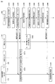
図9を参照して、HMDシステム100の制御構造について説明する。図9は、ある実施の形態に従うHMDシステム100において実行される処理の一部を表わすシーケンスチャートである。
[Control structure]
A control structure of the HMD system 100 will be described with reference to FIG. FIG. 9 is a sequence chart representing a part of processing executed in HMD system 100 according to an embodiment.

ステップS910にて、コンピュータ200のプロセッサ10は、仮想空間定義モジュール231として、仮想空間画像データを特定する。   In step S <b> 910, the processor 10 of the computer 200 identifies virtual space image data as the virtual space definition module 231.

ステップS920にて、プロセッサ10は、仮想カメラ1を初期化する。例えば、仮想カメラ1を仮想空間2において予め規定された中心点に配置し、仮想カメラ1の視線をユーザ190が向いている方向に向ける。   In step S920, the processor 10 initializes the virtual camera 1. For example, the virtual camera 1 is arranged at a predetermined center point in the virtual space 2 and the line of sight of the virtual camera 1 is directed in the direction in which the user 190 is facing.

ステップS930にて、プロセッサ10は、視界画像生成モジュール223として、初期の視界画像を表示するための視界画像データを生成する。生成された視界画像データは、視界画像生成モジュール223を介して通信制御モジュール250によってHMD装置110に送られる。   In step S930, the processor 10 generates view image data for displaying an initial view image as the view image generation module 223. The generated view image data is sent to the HMD device 110 by the communication control module 250 via the view image generation module 223.

ステップS932にて、HMD装置110のモニタ112は、コンピュータ200から受信した信号に基づいて、視界画像を表示する。HMD装置110を装着したユーザ190は、視界画像を視認すると仮想空間2を認識し得る。   In step S932, monitor 112 of HMD device 110 displays a view field image based on the signal received from computer 200. The user 190 wearing the HMD device 110 can recognize the virtual space 2 when viewing the visual field image.

ステップS934にて、HMDセンサ120は、HMD装置110から発信される複数の赤外線光に基づいて、HMD装置110の位置と傾きを検知する。検知結果は、動き検知データとして、コンピュータ200に送られる。   In step S934, HMD sensor 120 detects the position and inclination of HMD device 110 based on a plurality of infrared rays transmitted from HMD device 110. The detection result is sent to the computer 200 as motion detection data.

ステップS940にて、プロセッサ10は、HMD装置110の位置と傾きとに基づいて、HMD装置110を装着したユーザ190の視界方向を特定する。プロセッサ10は、アプリケーションプログラムを実行し、アプリケーションプログラムに含まれる命令に基づいて、仮想空間2においてオブジェクトを表示させる。ユーザ190は、そのアプリケーションプログラムの実行により仮想空間2において視認可能なコンテンツを楽しむ。ある局面において、当該コンテンツは、例えば、ボブスレーその他のそりを用いたスポーツ、スキー、スノーボード等を含む。ある実施の形態において、ユーザ190は、ボード180に着座し、モニタ112に表示された画像の推移に応じて姿勢を変え得る。   In step S940, the processor 10 specifies the viewing direction of the user 190 wearing the HMD device 110 based on the position and inclination of the HMD device 110. The processor 10 executes the application program and displays objects in the virtual space 2 based on instructions included in the application program. The user 190 enjoys content that is visible in the virtual space 2 by executing the application program. In one aspect, the content includes, for example, sports using a bobsled or other sled, skiing, snowboarding, and the like. In an embodiment, the user 190 can sit on the board 180 and change his / her posture according to the transition of the image displayed on the monitor 112.

ステップS942にて、傾きセンサ170は、ユーザ190が傾いている方向を検出する。検出された傾きを示す信号は、コンピュータ200に送られる。当該信号は、ボード180の傾斜角度を含む。例えば、ある局面において、ボブスレーのような滑降競技のアプリケーションプログラムが実行されている場合、ユーザ190の傾きに応じて、仮想空間2に存在する仮想ユーザが仮想空間2において表示されたボブスレーの進行方向を制御するシーンがあり得る。この場合、ユーザ190が体を傾けたときに、傾きセンサ170は、その傾斜方向を検出する。   In step S942, the tilt sensor 170 detects the direction in which the user 190 is tilting. A signal indicating the detected inclination is sent to the computer 200. The signal includes the tilt angle of the board 180. For example, in a certain situation, when a downhill competition application program such as a bobsled is being executed, the direction in which the virtual user existing in the virtual space 2 is displayed in the virtual space 2 according to the inclination of the user 190 There can be a scene that controls In this case, when the user 190 tilts his / her body, the tilt sensor 170 detects the tilt direction.

ステップS950にて、プロセッサ10は、傾きセンサ170から出力される信号に基づいて、仮想ユーザの移動方向と移動距離とを決定する。本実施の形態において、移動方向とは、仮想空間2において、仮想ユーザあるいは仮想ユーザが着座しているそりその他の器具が進む方向を含む。なお、別の局面において、移動方向のみが必要とされる場合に
は、プロセッサ10は、移動方向決定モジュール234として、移動方向のみを決定し得る。別の局面において、移動距離のみが必要とされる場合には、プロセッサ10は、移動距離決定モジュール235として、移動距離のみを決定し得る。
In step S950, processor 10 determines the moving direction and moving distance of the virtual user based on the signal output from tilt sensor 170. In the present embodiment, the moving direction includes a direction in which a virtual user or a sled or other instrument on which the virtual user is seated travels in the virtual space 2. In another aspect, when only the moving direction is required, the processor 10 can determine only the moving direction as the moving direction determination module 234. In another aspect, if only the travel distance is required, the processor 10 may determine only the travel distance as the travel distance determination module 235.

さらに他の局面において、プロセッサ10は、傾きセンサ170から出力される信号に基づいて、仮想ユーザの移動方向と移動速度とを決定する構成であってもよい。仮想ユーザの移動速度は、ボード180の傾斜角度が大きいほど速く設定され得る。   In yet another aspect, the processor 10 may be configured to determine the moving direction and moving speed of the virtual user based on a signal output from the tilt sensor 170. The moving speed of the virtual user can be set faster as the inclination angle of the board 180 is larger.

ステップS960にて、プロセッサ10は、決定された移動方向および移動距離に基づいて、仮想ユーザの移動後の視界を決定する。   In step S960, processor 10 determines the field of view of the virtual user after movement based on the determined movement direction and movement distance.

ステップS970にて、プロセッサ10は、決定された移動方向および移動距離に基づいて、仮想カメラ1の仮想空間2における位置および向きを決定する。   In step S970, processor 10 determines the position and orientation of virtual camera 1 in virtual space 2 based on the determined moving direction and moving distance.

ステップS980にて、プロセッサ10は、決定された仮想カメラ1の位置および向きに基づいて、視界領域を決定する。本実施の形態において、視界領域とは、仮想空間2において仮想ユーザが視認できる範囲を表わす。   In step S980, processor 10 determines a view field area based on the determined position and orientation of virtual camera 1. In the present embodiment, the visual field area represents a range in which the virtual user can visually recognize in the virtual space 2.

ステップS990にて、コンピュータ200は、決定された視界領域に応じて視界画像を表示するための視界画像データを生成し、生成した視界画像データをHMD装置110に出力する。視界画像データは、決定された移動方向に向かって仮想ユーザが高速に移動するように、仮想ユーザの周りの景色が高速に仮想ユーザの方に向かっている態様を表示可能に構成されている。   In step S990, the computer 200 generates view image data for displaying a view image in accordance with the determined view area, and outputs the generated view image data to the HMD device 110. The field-of-view image data is configured to be able to display an aspect in which the scenery around the virtual user is moving toward the virtual user at high speed so that the virtual user moves at high speed in the determined moving direction.

ステップS992にて、HMD装置110のモニタ112は、受信した視界画像データに基づいて視界画像を更新し、更新後の視界画像を表示する。ユーザ190は、更新後の視界画像、すなわち、移動方向に視線が移動したのちの視界を認識することができる。   In step S992, the monitor 112 of the HMD device 110 updates the view image based on the received view image data, and displays the updated view image. The user 190 can recognize the updated view image, that is, the view after the line of sight moves in the moving direction.

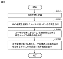
図10を参照して、コンピュータ200の制御構造についてさらに説明する。図10は、ボード180に着座したユーザ190の動作に応じてコンピュータ200が実行する処理の一部を表わすフローチャートである。   The control structure of the computer 200 will be further described with reference to FIG. FIG. 10 is a flowchart showing a part of processing executed by computer 200 in accordance with the operation of user 190 seated on board 180.

ステップS1010にて、プロセッサ10は、仮想空間定義モジュール231として、メモリ11において仮想空間2を定義する。   In step S <b> 1010, the processor 10 defines the virtual space 2 in the memory 11 as the virtual space definition module 231.

ステップS1020にて、プロセッサ10は、傾きセンサ170からの信号に基づいて、HMD装置110を装着してボード180に着座しているユーザ190が傾いている方向、具体的には、右、左、前または後を検出する。   In step S1020, the processor 10 determines, based on the signal from the tilt sensor 170, the direction in which the user 190 wearing the HMD device 110 and seated on the board 180 is tilted, specifically, right, left, Detect before or after.

ステップS1030にて、プロセッサ10は、ユーザ190の傾きに基づいて、仮想空間2を進行する仮想ユーザの移動方向を決定する。例えば、ユーザ190が一定時間右側に体を傾けた場合に、プロセッサ10は、仮想ユーザあるいは仮想ユーザが着座している乗り物が右側に移動すると判断する。他の局面において、ユーザ190が右側に体を一時的に傾ける動作を行なった回数に応じて、プロセッサ10は、仮想ユーザが右側に移動する方向を決定する。例えば、予め規定された時間内にユーザ190が体を傾けるための1回の動作を行なった場合、プロセッサ10は、仮想ユーザが進行方向に対して右側に1度移動すると決定する。ユーザ190が当該動作を10回行った場合、プロセッサ10は、仮想ユーザが右側に10度移動すると決定する。   In step S1030, the processor 10 determines the moving direction of the virtual user traveling in the virtual space 2 based on the inclination of the user 190. For example, when the user 190 leans to the right for a certain time, the processor 10 determines that the virtual user or the vehicle on which the virtual user is seated moves to the right. In another aspect, the processor 10 determines the direction in which the virtual user moves to the right according to the number of times that the user 190 has performed an action of temporarily tilting the body to the right. For example, when the user 190 performs one operation for tilting the body within a predetermined time, the processor 10 determines that the virtual user moves once to the right with respect to the traveling direction. If the user 190 performs the operation ten times, the processor 10 determines that the virtual user moves 10 degrees to the right.

別の局面において、ユーザ190が体を左側に傾ける動作を行なった場合にも、右側に
傾ける動作を行なった場合と同様に、プロセッサ10は、左側の移動方向を決定する。
In another aspect, when the user 190 performs an operation of tilting the body to the left side, the processor 10 determines the moving direction of the left side as in the case of performing the tilting operation to the right side.

別の実施の形態において、傾きセンサ170は、ユーザ190が体を前傾させたことを検知し得る。このときに、プロセッサ10は、傾きセンサ170からの信号に応じてユーザ190が体を前に傾けたことを検知し、傾斜角度に基づいて移動距離を決定し得る。例えば、前方への1度の傾斜が検知された場合に、仮想ユーザを10m移動させることが、プロセッサ10が実行しているプログラムにおいて予め規定されている場合、プロセッサ10は、ユーザ190が前方に5度傾いたことを検知すると、仮想空間2において仮想ユーザを50m移動させることを決定する。   In another embodiment, the tilt sensor 170 may detect that the user 190 has tilted the body forward. At this time, the processor 10 may detect that the user 190 has tilted the body forward according to a signal from the tilt sensor 170 and may determine the moving distance based on the tilt angle. For example, when it is preliminarily specified in the program executed by the processor 10 that the virtual user is moved 10 m when a forward tilt of 1 degree is detected, the processor 10 causes the user 190 to move forward. When it is detected that the tilt is 5 degrees, it is determined to move the virtual user 50 m in the virtual space 2.

ステップS1040にて、プロセッサ10は、仮想オブジェクト生成モジュール232として、仮想空間2における仮想ユーザの視界が、ステップSS1030において決定された移動方向に移動するように、HMD装置110に視界画像を表示させるための視界画像データを生成する。ある実施の形態に従うと、プロセッサ10は、移動方向に加えて、ユーザ190の傾きが継続している時間に応じた移動距離が反映された視界画像データを生成する。プロセッサ10は、生成した視界画像データをHMD装置110に送信し、当該視界画像データに基づいて視界画像をモニタ112に表示させる。   In step S1040, the processor 10 causes the HMD device 110 to display a field-of-view image as the virtual object generation module 232 so that the field of view of the virtual user in the virtual space 2 moves in the movement direction determined in step SS1030. Field of view image data is generated. According to an embodiment, the processor 10 generates visual field image data in which a moving distance corresponding to a time during which the user 190 continues to tilt is reflected in addition to the moving direction. The processor 10 transmits the generated view image data to the HMD device 110 and causes the monitor 112 to display the view image based on the view image data.

[着座しているユーザの移動]
図11〜図13を参照して、ユーザ190の傾きの検出の一態様について説明する。
[Moving seated users]
With reference to FIGS. 11 to 13, an aspect of detection of the inclination of the user 190 will be described.

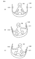
図11は、ある実施の形態において、ユーザ190がボード180に着座している態様を表す図である。分図Aは、HMD装置110(図示しない)を装着したユーザ190がボード180において水平状態を維持して着座している態様を表す。分図Bは、ユーザ190が体重移動を行ない、ユーザ190から見て左側にボード180を傾けた態様を表す。分図Cは、ユーザが体重移動を行ない、ユーザ190から見て右側にボード180を傾けた状態を表す。ボード180が傾くと、傾きセンサ170は、その方向きに応じた信号を出力する。出力された信号は、コンピュータ200に入力される。傾きが検知される方向は、分図Bに示される左、分図Cに示される右に限られず、ある実施の形態において、傾きセンサ170は、ユーザ190が前方に体重移動を行なった場合の前方への傾き、あるいは、ユーザ190が後方に体重移動を行なった場合の後方への傾きも検知し得る。   FIG. 11 is a diagram illustrating an aspect in which a user 190 is seated on a board 180 in an embodiment. The partial diagram A represents a mode in which the user 190 wearing the HMD device 110 (not shown) is seated on the board 180 while maintaining a horizontal state. The partial diagram B shows a state in which the user 190 moves the weight and the board 180 is tilted to the left as viewed from the user 190. The partial diagram C represents a state in which the user moves the weight and tilts the board 180 to the right as viewed from the user 190. When the board 180 tilts, the tilt sensor 170 outputs a signal corresponding to the direction. The output signal is input to the computer 200. The direction in which the inclination is detected is not limited to the left shown in the division diagram B and the right shown in the division diagram C. In an embodiment, the inclination sensor 170 is used when the user 190 moves weight forward. The forward tilt or the backward tilt when the user 190 moves the weight backward can also be detected.

図12は、ある実施の形態において、ユーザ190がボード180に立っている態様を表す図である。分図Aは、HMD装置110(図示しない)を装着したユーザ190がボード180において水平状態を維持して立っている態様を表す。分図Bは、ユーザ190が体重移動を行ない、ユーザ190から見て左側にボード180を傾けた態様を表す。分図Cは、ユーザが体重移動を行ない、ユーザ190から見て右側にボード180を傾けた状態を表す。ボード180が傾くと、傾きセンサ170は、その方向きに応じた信号を出力する。出力された信号は、コンピュータ200に入力される。傾きが検知される方向は、分図Bに示される左、分図Cに示される右に限られず、ある実施の形態において、傾きセンサ170は、ユーザ190が前方に体重移動を行なった場合の前方への傾き、あるいは、ユーザ190が後方に体重移動を行なった場合の後方への傾きも検知し得る。ユーザ190は、自身の体重移動に応じて、仮想空間2における仮想ユーザの移動方向を予測できるので、没入感を損なうことなく、所謂映像酔い(VR酔い)を防止することができる。   FIG. 12 is a diagram illustrating a state in which a user 190 stands on a board 180 in an embodiment. The partial diagram A represents a mode in which the user 190 wearing the HMD device 110 (not shown) is standing on the board 180 while maintaining a horizontal state. The partial diagram B shows a state in which the user 190 moves the weight and the board 180 is tilted to the left as viewed from the user 190. The partial diagram C represents a state in which the user moves the weight and tilts the board 180 to the right as viewed from the user 190. When the board 180 tilts, the tilt sensor 170 outputs a signal corresponding to the direction. The output signal is input to the computer 200. The direction in which the inclination is detected is not limited to the left shown in the division diagram B and the right shown in the division diagram C. In an embodiment, the inclination sensor 170 is used when the user 190 moves weight forward. The forward tilt or the backward tilt when the user 190 moves the weight backward can also be detected. Since the user 190 can predict the moving direction of the virtual user in the virtual space 2 according to his / her weight shift, so-called video sickness (VR sickness) can be prevented without impairing the sense of immersion.

図13を参照して、傾きの検知の他の態様について説明する。図13は、ある実施の形態において、ユーザ190がそり1300に着座している態様を表す図である。そり1300の両側面には、タッチセンサ1370,1371がそれぞれ配置されている。タッチセンサ1370,1371の出力は、コンピュータ200の入力インターフェイスに接続
されている。ある局面において、一つ以上のそり1300は、遊技場において提供され得る。
With reference to FIG. 13, another aspect of inclination detection will be described. FIG. 13 is a diagram illustrating an aspect in which a user 190 is seated on a sled 1300 in an embodiment. Touch sensors 1370 and 1371 are arranged on both sides of the sled 1300, respectively. Outputs of the touch sensors 1370 and 1371 are connected to an input interface of the computer 200. In certain aspects, one or more sleds 1300 may be provided at a playground.

分図Aは、HMD装置110(図示しない)を装着したユーザ190がそり1300において水平状態を維持して着座している態様を表す。このとき、ユーザ190はタッチセンサ1370および1371に触れていない。   The partial diagram A represents a mode in which the user 190 wearing the HMD device 110 (not shown) is seated while maintaining a horizontal state on the sled 1300. At this time, the user 190 is not touching the touch sensors 1370 and 1371.

分図Bは、ユーザ190が体重移動を行ない、ユーザ190から見て右側にそり1300を傾けた態様を表す。そり1300が右側に傾いてユーザの右手がタッチセンサ1370に触れると、タッチセンサ1370から出力された信号は、コンピュータ200に入力される。プロセッサ10は、その信号に基づいて、そり1300が右側に傾いたことを検知する。さらに、プロセッサ10は、仮想空間2において仮想ユーザの右前方からの視界がユーザ190によって認識されるように、視界画像データを生成する。プロセッサ10が視界画像データをHMD装置110に送信して、モニタ112が視界画像データに基づく画像を表示する。ユーザ190は、その画像を見ると、仮想空間2において右方向に移動しているように認識する。   The partial diagram B represents a state in which the user 190 moves the weight and the sled 1300 is tilted to the right as viewed from the user 190. When the sled 1300 is tilted to the right and the user's right hand touches the touch sensor 1370, a signal output from the touch sensor 1370 is input to the computer 200. The processor 10 detects that the sled 1300 has tilted to the right based on the signal. Further, the processor 10 generates view image data so that the user 190 can recognize the view from the right front of the virtual user in the virtual space 2. The processor 10 transmits the view image data to the HMD device 110, and the monitor 112 displays an image based on the view image data. When viewing the image, the user 190 recognizes that the user 190 is moving rightward in the virtual space 2.

分図Cは、ユーザ190が体重移動を行ない、ユーザ190から見て左側にそり1300を傾けた状態を表す。そり1300が左側に傾いてユーザの左手がタッチセンサ1371に触れると、タッチセンサ1371から出力された信号は、コンピュータ200に入力される。プロセッサ10は、その信号に基づいて、そり1300が左側に傾いたことを検知する。さらに、プロセッサ10は、仮想空間2において仮想ユーザの左前方からの視界がユーザ190によって認識されるように、視界画像データを生成する。プロセッサ10が視界画像データをHMD装置110に送信して、モニタ112が視界画像データに基づく画像を表示する。ユーザ190は、その画像を見ると、仮想空間2において左方向に移動しているように認識する。   The partial diagram C represents a state in which the user 190 moves the weight and tilts the sled 1300 to the left as viewed from the user 190. When the sled 1300 is tilted to the left and the user's left hand touches the touch sensor 1371, a signal output from the touch sensor 1371 is input to the computer 200. The processor 10 detects that the sled 1300 is tilted to the left based on the signal. Further, the processor 10 generates view image data so that the user 190 can recognize the view from the left front of the virtual user in the virtual space 2. The processor 10 transmits the view image data to the HMD device 110, and the monitor 112 displays an image based on the view image data. When viewing the image, the user 190 recognizes that it is moving leftward in the virtual space 2.

なお、図13に示される例でも、タッチセンサ1370,1371の代わりに、図11または図12と同様に、傾きセンサ170が、そり1300の底部に配置されてもよい。   In the example shown in FIG. 13, instead of the touch sensors 1370 and 1371, the tilt sensor 170 may be arranged at the bottom of the sled 1300 as in FIG. 11 or FIG. 12.

次に、図14〜図16を参照して、仮想空間2における仮想ユーザの移動について説明する。ある実施の形態において、HMD装置110を装着したユーザ190は、仮想ユーザとして、仮想空間2における視界画像1400を視認している。   Next, movement of the virtual user in the virtual space 2 will be described with reference to FIGS. In an embodiment, the user 190 wearing the HMD device 110 is viewing the visual field image 1400 in the virtual space 2 as a virtual user.

図14は、ユーザ190が着座して又は立っているボード180またはそり1300が水平に維持されている場合を説明するための図である。このとき、プロセッサ10は、傾きセンサ170またはタッチセンサ1370,1371から出力される信号に基づき、ユーザ190は水平状態を維持していると判断する。さらに、プロセッサ10は、仮想空間2において水平状態の画像が視認されるような視界画像データを生成し、HMD装置110のモニタ112に当該視界画像データを送信する。   FIG. 14 is a diagram for explaining a case where the board 180 or the sled 1300 on which the user 190 is seated or standing is kept horizontal. At this time, the processor 10 determines that the user 190 is maintaining a horizontal state based on a signal output from the tilt sensor 170 or the touch sensors 1370 and 1371. Furthermore, the processor 10 generates view image data such that a horizontal image is visually recognized in the virtual space 2, and transmits the view image data to the monitor 112 of the HMD device 110.

分図Aに示されるように、モニタ112がその視界画像データに基づいて画像を表示した場合には、ユーザ190は、仮想ユーザとして視界画像1400を認識する。このとき、分図Bに示されるように、仮想ユーザに対応する仮想カメラ1は、仮想ユーザの視野に応じた視界領域23をとらえている。   As shown in the partial diagram A, when the monitor 112 displays an image based on the view image data, the user 190 recognizes the view image 1400 as a virtual user. At this time, as shown in the partial diagram B, the virtual camera 1 corresponding to the virtual user captures the visual field region 23 corresponding to the visual field of the virtual user.

[右側への移動]
図15は、水平状態を維持していたユーザ190が右側に傾いて、ボード180またはそり1300を右側に傾けた場合を説明するための図である。このとき、プロセッサ10は、傾きセンサ170またはタッチセンサ1370,1371から出力される信号に基づ
き、ユーザ190が右側に傾いていると判断する。さらに、プロセッサ10は、仮想空間2における仮想ユーザが当所いた場所(例えば、図14参照)から右側に移動していると認識される視界画像データを生成する。例えば、プロセッサ10は、仮想空間2において認識される画像が右から左に流れるような視界画像を表示するための視界画像データを生成し、視界画像データをHMD装置110に送信する。
[Move to the right]
FIG. 15 is a diagram for explaining a case where the user 190 who has maintained the horizontal state tilts to the right and tilts the board 180 or the sled 1300 to the right. At this time, the processor 10 determines that the user 190 is tilted to the right based on a signal output from the tilt sensor 170 or the touch sensors 1370 and 1371. Further, the processor 10 generates view field image data that is recognized as moving to the right side from the place (for example, see FIG. 14) where the virtual user is located in the virtual space 2. For example, the processor 10 generates view image data for displaying a view image in which an image recognized in the virtual space 2 flows from right to left, and transmits the view image data to the HMD device 110.

分図Aに示されるように、モニタ112が、当該視界画像データに基づく視界画像1500を表示する。視界画像1400において右に表示されていた木1410が視界画像1500の中心に移動している。   As shown in the partial diagram A, the monitor 112 displays a view field image 1500 based on the view field image data. The tree 1410 displayed on the right side in the view field image 1400 has moved to the center of the view field image 1500.

分図Bに示されるように、このような移動は、例えば、仮想空間2において仮定される仮想カメラ1が木1410の正面に移動することに相当する。プロセッサ10は、仮想カメラ1の移動に応じて認識される画像と同様の画像を表示するために視界画像データを生成する。   As shown in the partial diagram B, such movement corresponds to, for example, that the virtual camera 1 assumed in the virtual space 2 moves in front of the tree 1410. The processor 10 generates view field image data in order to display an image similar to the image recognized in accordance with the movement of the virtual camera 1.

視界画像1400から視界画像1500への推移は、ユーザ190が体重を右側に移動したことに基づいて行なわれる。このようにすると、ユーザ190は、右側への体重移動という自らの動作に応じて、視界画像の推移による仮想空間2における移動を認識できるので、ユーザ190の傾きと仮想空間2における移動方向とが連動することになる。その結果、所謂VR酔いの発生が抑制され得る。   Transition from the view image 1400 to the view image 1500 is performed based on the fact that the user 190 has moved the weight to the right. In this way, the user 190 can recognize the movement in the virtual space 2 due to the transition of the view image according to his / her own movement of weight to the right side, so that the inclination of the user 190 and the moving direction in the virtual space 2 are determined. It will be linked. As a result, the occurrence of so-called VR sickness can be suppressed.

[左側への移動]
図16は、水平状態を維持していたユーザ190が左側に傾いて、ボード180またはそり1300を左側に傾けた場合を説明するための図である。このとき、プロセッサ10は、傾きセンサ170またはタッチセンサ1370,1371から出力される信号に基づき、ユーザ190が左側に傾いていると判断する。さらに、プロセッサ10は、仮想空間2における仮想ユーザが当所いた場所(例えば、図14参照)から左側に移動していると認識される視界画像データを生成する。例えば、プロセッサ10は、仮想空間2において認識される画像が左から右に流れるような視界画像を表示するための視界画像データを生成し、視界画像データをHMD装置110に送信する。
[Move to the left]
FIG. 16 is a diagram for explaining a case where the user 190 who has maintained the horizontal state tilts to the left and tilts the board 180 or the sled 1300 to the left. At this time, the processor 10 determines that the user 190 is tilted to the left based on a signal output from the tilt sensor 170 or the touch sensors 1370 and 1371. Further, the processor 10 generates view field image data that is recognized as moving to the left side from the place where the virtual user is located in the virtual space 2 (for example, see FIG. 14). For example, the processor 10 generates view image data for displaying a view image in which an image recognized in the virtual space 2 flows from left to right, and transmits the view image data to the HMD device 110.

分図Aに示されるように、モニタ112が、当該視界画像データに基づく視界画像1600を表示する。視界画像1400において左に表示されていた山1420が視界画像1600の中心に移動している。   As shown in the partial diagram A, the monitor 112 displays a view image 1600 based on the view image data. The mountain 1420 displayed on the left in the view field image 1400 has moved to the center of the view field image 1600.

分図Bに示されるように、このような移動は、例えば、仮想空間2において仮定される仮想カメラ1が山1420の正面に移動することに相当する。プロセッサ10は、仮想カメラ1の移動に応じて認識される画像と同様の画像を表示するために視界画像データを生成する。   As shown in the partial diagram B, such movement corresponds to, for example, that the virtual camera 1 assumed in the virtual space 2 moves in front of the mountain 1420. The processor 10 generates view field image data in order to display an image similar to the image recognized in accordance with the movement of the virtual camera 1.

視界画像1400から視界画像1600への推移は、ユーザ190が体重を左側に移動したことに基づいて行なわれる。このようにすると、ユーザ190は、左側への体重移動という自らの動作に応じて、視界画像の推移による仮想空間2における移動を認識できるので、ユーザ190の傾きと仮想空間2における移動方向とが連動することになる。その結果、所謂VR酔いの発生が抑制され得る。   Transition from the view image 1400 to the view image 1600 is performed based on the fact that the user 190 has moved his / her weight to the left. In this way, the user 190 can recognize the movement in the virtual space 2 due to the transition of the field-of-view image in accordance with his / her own movement of weight to the left, so that the inclination of the user 190 and the movement direction in the virtual space 2 are determined. It will be linked. As a result, the occurrence of so-called VR sickness can be suppressed.

[前方への移動]
図17は、水平状態を維持していたユーザ190が前に傾いて、ボード180を前方に傾けた場合を説明するための図である。プロセッサ10は、傾きセンサ170から出力される信号に基づき、ユーザ190が前方に傾いていると判断する。さらに、プロセッサ1
0は、仮想空間2における仮想ユーザが当所いた場所(例えば、図14参照)から前方に移動していると認識される視界画像データを生成する。例えば、プロセッサ10は、仮想空間2において認識される画像が高速に近づいてくるような視界画像を表示するための視界画像データを生成し、視界画像データをHMD装置110に送信する。
[Move forward]
FIG. 17 is a diagram for explaining a case where the user 190 who has maintained the horizontal state leans forward and tilts the board 180 forward. The processor 10 determines that the user 190 is tilted forward based on the signal output from the tilt sensor 170. In addition, processor 1
0 generates view field image data that is recognized as moving forward from a location (for example, see FIG. 14) where the virtual user is located in the virtual space 2. For example, the processor 10 generates visual field image data for displaying a visual field image such that an image recognized in the virtual space 2 approaches at high speed, and transmits the visual field image data to the HMD device 110.

分図Aに示されるように、モニタ112が、当該視界画像データに基づく視界画像1700を表示する。視界画像1400において遠方に小さく表示されていた木1410および山1420は、それぞれ、仮想空間2における移動距離に応じて大きく表示される。なお、仮想空間2における移動距離は、ある局面において、例えば、ユーザ190による前傾の角度と、予め定められた単位角度当たりの移動距離とに基づいて算出され得る。当該移動距離は、別の局面において、前傾の状態が継続していた時間と、予め定められた単位時間当たりの移動距離とに基づいて算出されてもよい。   As shown in the partial diagram A, the monitor 112 displays a view image 1700 based on the view image data. The tree 1410 and the mountain 1420 that are displayed small in the distance in the view field image 1400 are each displayed large according to the moving distance in the virtual space 2. Note that the movement distance in the virtual space 2 can be calculated based on, for example, a forward tilt angle by the user 190 and a predetermined movement distance per unit angle in a certain situation. In another aspect, the moving distance may be calculated based on the time during which the forward leaning state has continued and a predetermined moving distance per unit time.

分図Bに示されるように、仮想空間2における視界画像の移動は、例えば、仮想空間2において仮定される仮想カメラ1が木1410や山1420の方に向かって高速に移動することに相当する。プロセッサ10は、仮想カメラ1の移動に応じて認識される画像と同様の画像を表示するために視界画像データを生成する。   As shown in the partial diagram B, the movement of the view field image in the virtual space 2 corresponds to, for example, the virtual camera 1 assumed in the virtual space 2 moving at high speed toward the tree 1410 or the mountain 1420. . The processor 10 generates view field image data in order to display an image similar to the image recognized in accordance with the movement of the virtual camera 1.

視界画像1400から視界画像1700への推移は、ユーザ190が体重を前に移動したことに基づいて行なわれる。ユーザ190は、体重移動という自らの動作に応じて、仮想空間2における移動を認識できるので、ユーザ190の傾きと仮想空間2における移動方向とが連動することになる。その結果、所謂VR酔いの発生が抑制され得る。   Transition from the view image 1400 to the view image 1700 is performed based on the fact that the user 190 has moved the weight forward. Since the user 190 can recognize the movement in the virtual space 2 according to his / her own movement of weight, the inclination of the user 190 and the moving direction in the virtual space 2 are linked. As a result, the occurrence of so-called VR sickness can be suppressed.

[後方への移動]
図18は、水平状態を維持していたユーザ190が後方に傾いて、ボード180を後方に傾けた場合を説明するための図である。プロセッサ10は、傾きセンサ170から出力される信号に基づき、ユーザ190が後方に傾いていると判断する。さらに、プロセッサ10は、仮想空間2における仮想ユーザが当所いた場所(例えば、図14参照)から後方に移動していると認識される視界画像データを生成する。例えば、プロセッサ10は、仮想空間2において認識される画像が高速に遠ざかるような視界画像を表示するための視界画像データを生成し、視界画像データをHMD装置110に送信する。
[Move backward]
FIG. 18 is a diagram for explaining a case where the user 190 who has maintained the horizontal state tilts backward and tilts the board 180 backward. The processor 10 determines that the user 190 is tilted backward based on the signal output from the tilt sensor 170. Furthermore, the processor 10 generates view field image data that is recognized as moving backward from a location (for example, see FIG. 14) where the virtual user is located in the virtual space 2. For example, the processor 10 generates visual field image data for displaying a visual field image such that an image recognized in the virtual space 2 moves away at high speed, and transmits the visual field image data to the HMD device 110.

分図Aに示されるように、モニタ112が、当該視界画像データに基づく視界画像1800を表示する。視界画像1400において表示されていた木1410および山1420は、それぞれ、図14に示されていた場合よりも小さく表示される。例えば、木1410および山1420は、仮想空間2における移動距離に応じて小さく表示される。なお、仮想空間2における移動距離は、ある局面において、例えば、ユーザ190による後傾の角度と、予め定められた単位角度当たりの移動距離とに基づいて算出され得る。当該移動距離は、別の局面において、後傾の状態が継続していた時間と、予め定められた単位時間当たりの移動距離とに基づいて算出されてもよい。   As shown in the partial diagram A, the monitor 112 displays a view image 1800 based on the view image data. The tree 1410 and the mountain 1420 displayed in the field-of-view image 1400 are each displayed smaller than the case shown in FIG. For example, the tree 1410 and the mountain 1420 are displayed small according to the moving distance in the virtual space 2. Note that the movement distance in the virtual space 2 can be calculated based on, for example, an angle of backward tilt by the user 190 and a movement distance per predetermined unit angle in a certain situation. In another aspect, the movement distance may be calculated based on a time during which the backward tilt state has continued and a predetermined movement distance per unit time.

分図Bに示されるように、仮想空間2における視界画像の移動は、例えば、仮想空間2において仮定される仮想カメラ1が木1410や山1420から遠ざかる方向に高速に移動することに相当する。プロセッサ10は、仮想カメラ1の移動に応じて認識される画像と同様の画像を表示するために視界画像データを生成する。   As shown in the partial diagram B, the movement of the view image in the virtual space 2 corresponds to, for example, the virtual camera 1 assumed in the virtual space 2 moving at a high speed in a direction away from the tree 1410 and the mountain 1420. The processor 10 generates view field image data in order to display an image similar to the image recognized in accordance with the movement of the virtual camera 1.

視界画像1400から視界画像1800への推移は、ユーザ190が体重を後に移動したことに基づいて行なわれる。ユーザ190は、体重移動という自らの動作に応じて、仮想空間2における移動を認識できるので、前傾の場合と同様に、ユーザ190の傾きと仮想空間2における移動方向とが連動することになる。その結果、所謂VR酔いの発生が抑
制され得る。
Transition from the view image 1400 to the view image 1800 is performed based on the fact that the user 190 has moved his weight later. Since the user 190 can recognize the movement in the virtual space 2 according to his / her own movement of weight movement, the inclination of the user 190 and the moving direction in the virtual space 2 are linked as in the case of the forward inclination. . As a result, the occurrence of so-called VR sickness can be suppressed.

以上のようにして、ある実施の形態によれば、現実空間においてユーザ190が傾いている方向に基づき、仮想空間2における仮想ユーザの移動方向が決定されるので、ユーザ190の傾きと仮想空間2における移動方向とが連動することになる。その結果、仮想空間2において仮想ユーザの移動が行なわれても、その時の画像を視認したユーザ190に対するVR酔いの発生が抑制され得る。なお、上記の実施の形態でそれぞれ説明された各特徴は、適宜、組み合わせられ得る。例えば、水平方向を維持していたユーザ190がボード180を傾けた場合の前方または後方の成分については、仮想空間2において仮想カメラ1の基準視線5の方向へ仮想ユーザが前進または後退するように移動するものとして移動距離の算出を行い、ユーザがボード180を右側または左側へと傾ける傾斜の度合いに応じて、仮想カメラ1を、ヨー方向(v軸)周りに回転させ得る。   As described above, according to an embodiment, since the moving direction of the virtual user in the virtual space 2 is determined based on the direction in which the user 190 is inclined in the real space, the inclination of the user 190 and the virtual space 2 are determined. The movement direction in is linked. As a result, even if a virtual user moves in the virtual space 2, the occurrence of VR sickness for the user 190 who visually recognizes the image at that time can be suppressed. Note that the features described in the above embodiments can be combined as appropriate. For example, regarding the forward or backward component when the user 190 who has maintained the horizontal direction tilts the board 180, the virtual user moves forward or backward in the direction of the reference line of sight 5 of the virtual camera 1 in the virtual space 2. The moving distance is calculated as moving, and the virtual camera 1 can be rotated around the yaw direction (v-axis) according to the degree of inclination by which the user tilts the board 180 to the right or left.

今回開示された実施の形態はすべての点で例示であって制限的なものではないと考えられるべきである。本発明の範囲は上記した説明ではなくて特許請求の範囲によって示され、特許請求の範囲と均等の意味および範囲内でのすべての変更が含まれることが意図される。   The embodiment disclosed this time should be considered as illustrative in all points and not restrictive. The scope of the present invention is defined by the terms of the claims, rather than the description above, and is intended to include any modifications within the scope and meaning equivalent to the terms of the claims.

1 仮想カメラ、2 仮想空間、5 基準視線、10 プロセッサ、11 メモリ、12 ストレージ、13 入出力インターフェイス、14 通信インターフェイス、15 バス、19 ネットワーク、21 中心、22 仮想空間画像、23 視界領域、24,25 領域、26,1400,1500,1600,1700,1800 視界画像、100 システム、110 HMD装置、112 モニタ、114 センサ、120 HMDセンサ、130 モーションセンサ、140 注視センサ、150 サーバ、160 コントローラ、170 傾きセンサ、180 ボード、190 ユーザ、200 コンピュータ、220 表示制御モジュール、221 仮想カメラ制御モジュール、222 視界領域決定モジュール、223 視界画像生成モジュール、224 基準視線特定モジュール、230 仮想空間制御モジュール、231 仮想空間定義モジュール、232 仮想オブジェクト生成モジュール、233 物体制御モジュール、234 移動方向決定モジュール、235 移動距離決定モジュール、240 メモリモジュール、241 空間情報、242 オブジェクト情報、243 ユーザ情報、250 通信制御モジュール、1300 そり、1370,1371 タッチセンサ、1410 木、1420 山。   1 virtual camera, 2 virtual space, 5 reference line of sight, 10 processor, 11 memory, 12 storage, 13 input / output interface, 14 communication interface, 15 bus, 19 network, 21 center, 22 virtual space image, 23 viewing area, 24, 25 area, 26, 1400, 1500, 1600, 1700, 1800 view image, 100 system, 110 HMD device, 112 monitor, 114 sensor, 120 HMD sensor, 130 motion sensor, 140 gaze sensor, 150 server, 160 controller, 170 tilt Sensor, 180 board, 190 user, 200 computer, 220 display control module, 221 virtual camera control module, 222 view area determination module, 223 view image generation module 224, reference gaze identification module, 230 virtual space control module, 231 virtual space definition module, 232 virtual object generation module, 233 object control module, 234 movement direction determination module, 235 movement distance determination module, 240 memory module, 241 space information 242 Object information, 243 User information, 250 Communication control module, 1300 Sled, 1370, 1371 Touch sensor, 1410 Tree, 1420 Mountain.

Claims (13)

コンピュータがヘッドマウントディスプレイ装置に仮想空間を提供するための方法であって、
仮想空間を定義するステップと、
前記ヘッドマウントディスプレイ装置のユーザが傾いている方向を検出するステップと、
検出された前記傾いている方向に基づいて前記仮想空間における前記ユーザの移動方向を決定するステップと、
前記仮想空間における前記ユーザの視界が、決定された前記ユーザの移動方向に移動するように、前記ヘッドマウントディスプレイ装置に前記視界を表示させるステップとを含む、仮想空間を提供するための方法。
A method for a computer to provide virtual space to a head mounted display device, comprising:
Defining a virtual space;
Detecting a direction in which a user of the head mounted display device is tilted;
Determining the direction of movement of the user in the virtual space based on the detected tilted direction;
Causing the head-mounted display device to display the field of view so that the field of view of the user in the virtual space moves in the determined direction of movement of the user.
前記移動方向を決定するステップは、前記ユーザの傾きが継続している時間に応じて、前記移動方向を決定することを含む、請求項1に記載の方法。   The method according to claim 1, wherein the step of determining the moving direction includes determining the moving direction according to a time during which the inclination of the user continues. 前記移動方向を決定するステップは、前記ユーザが傾いている方向に応じて、前記移動方向を決定することを含む、請求項1に記載の方法。   The method of claim 1, wherein the step of determining the direction of movement includes determining the direction of movement in response to a direction in which the user is tilting. 検出された前記ユーザの傾きに基づいて前記仮想空間における前記ユーザの移動距離を決定するステップをさらに備え、
前記視界を表示させるステップは、前記ユーザの視界が前記移動方向に向かって前記移動距離だけ移動するように、前記視界を表示させることを含む、請求項1〜3のいずれかに記載の方法。
Determining a moving distance of the user in the virtual space based on the detected inclination of the user;
The method according to claim 1, wherein the step of displaying the visual field includes displaying the visual field so that the visual field of the user moves in the moving direction by the moving distance.
コンピュータがヘッドマウントディスプレイ装置に仮想空間を提供するための方法であって、
仮想空間を定義するステップと、
前記ヘッドマウントディスプレイ装置のユーザの傾きを検出するステップと、
検出された前記ユーザの傾きに基づいて前記仮想空間における前記ユーザの移動距離を決定するステップと、
前記仮想空間における前記ユーザの視界が、決定された前記ユーザの移動距離だけ移動するように、前記ヘッドマウントディスプレイ装置に前記視界を表示させるステップとを含む、仮想空間を提供するための方法。
A method for a computer to provide virtual space to a head mounted display device, comprising:
Defining a virtual space;
Detecting a tilt of a user of the head mounted display device;
Determining a moving distance of the user in the virtual space based on the detected inclination of the user;
Displaying the field of view on the head-mounted display device so that the field of view of the user in the virtual space moves by the determined movement distance of the user.
前記移動距離を決定するステップは、前記ユーザの傾きが継続している時間に応じて、前記移動距離を決定することを含む、請求項4または5に記載の方法。   The method according to claim 4 or 5, wherein the step of determining the moving distance includes determining the moving distance according to a time during which the user's inclination continues. 前記移動距離を決定するステップは、前記ユーザの傾きの程度に応じて、前記移動距離を決定することを含む、請求項4または5に記載の方法。   The method according to claim 4 or 5, wherein the step of determining the moving distance includes determining the moving distance according to a degree of inclination of the user. 前記ユーザの傾きを検出するステップは、前記ユーザによる体重移動を伴う動作または姿勢に基づく加速度を検出するステップを含む、請求項1〜7のいずれかに記載の方法。   The method according to claim 1, wherein the step of detecting the inclination of the user includes a step of detecting an acceleration based on an action or posture accompanied by weight movement by the user. 前記ユーザの傾きを検出するステップは、前記ユーザから作用する荷重を検出することを含む、請求項8に記載の方法。   The method of claim 8, wherein detecting the user tilt includes detecting a load acting from the user. 請求項1〜9のいずれかに記載の方法をコンピュータに実現させる、プログラム。   The program which makes a computer implement | achieve the method in any one of Claims 1-9. システムであって、
ヘッドマウントディスプレイ装置と、
前記ヘッドマウントディスプレイ装置に仮想空間を提供するためのコンピュータと、
前記ヘッドマウントディスプレイ装置のユーザが傾いていることを検出するためのセンサとを備え、
前記コンピュータは、
一連の命令を格納するためのメモリと、
前記一連の命令を実行するためのプロセッサとを備えており、
前記一連の命令が前記プロセッサによって実行されると、
前記プロセッサは、
仮想空間を定義し、
前記ヘッドマウントディスプレイ装置のユーザが傾いている方向を検出し、
前記傾いている方向に基づいて、前記仮想空間における前記ユーザの移動方向を決定し、
前記仮想空間における前記ユーザの視界が、決定された前記ユーザの移動方向に移動するように、前記ヘッドマウントディスプレイ装置に前記視界を表示させるように構成されている、システム。
A system,
A head-mounted display device;
A computer for providing a virtual space to the head mounted display device;
A sensor for detecting that the user of the head mounted display device is tilted,
The computer
A memory for storing a series of instructions;
A processor for executing the series of instructions,
When the sequence of instructions is executed by the processor,
The processor is
Define a virtual space,
Detecting the direction in which the user of the head-mounted display device is tilted;
Based on the tilted direction, determine the direction of movement of the user in the virtual space,
A system configured to display the field of view on the head mounted display device so that the field of view of the user in the virtual space moves in the determined moving direction of the user.
前記プロセッサは、検出された前記ユーザの傾きに基づいて前記仮想空間における前記ユーザの移動距離を決定するようにさらに構成されており、
前記視界を表示させることは、前記ユーザの視界が前記移動方向に向かって前記移動距離だけ移動するように、前記視界を表示させることを含む、請求項11に記載のシステム。
The processor is further configured to determine a distance traveled by the user in the virtual space based on the detected inclination of the user;
The system according to claim 11, wherein displaying the field of view includes displaying the field of view so that the field of view of the user moves in the moving direction by the moving distance.
システムであって、
ヘッドマウントディスプレイ装置と、
前記ヘッドマウントディスプレイ装置に仮想空間を提供するためのコンピュータと、
前記ヘッドマウントディスプレイ装置のユーザの傾きを検出するためのセンサとを備え、
前記コンピュータは、
一連の命令を格納するためのメモリと、
前記一連の命令を実行するためのプロセッサとを備えており、
前記一連の命令が前記プロセッサによって実行されると、
前記プロセッサは、
仮想空間を定義し、
前記ヘッドマウントディスプレイ装置のユーザの傾きを検出し、
検出された前記ユーザの傾きに基づいて前記仮想空間における前記ユーザの移動距離を決定し、
前記仮想空間における前記ユーザの視界が、決定された前記ユーザの移動距離だけ移動するように、前記ヘッドマウントディスプレイ装置に前記視界を表示させるように構成されている、システム。
A system,
A head-mounted display device;
A computer for providing a virtual space to the head mounted display device;
A sensor for detecting a tilt of a user of the head mounted display device,
The computer
A memory for storing a series of instructions;
A processor for executing the series of instructions,
When the sequence of instructions is executed by the processor,
The processor is
Define a virtual space,
Detecting the tilt of the user of the head mounted display device;
Determining the moving distance of the user in the virtual space based on the detected inclination of the user;
The system configured to display the field of view on the head mounted display device such that the field of view of the user in the virtual space moves by the determined moving distance of the user.
JP2017092629A 2017-05-08 2017-05-08 Method for providing virtual space, program to cause computer to realize the same and system to provide virtual space Pending JP2017220224A (en)

Priority Applications (1)

Application Number Priority Date Filing Date Title
JP2017092629A JP2017220224A (en) 2017-05-08 2017-05-08 Method for providing virtual space, program to cause computer to realize the same and system to provide virtual space

Applications Claiming Priority (1)

Application Number Priority Date Filing Date Title
JP2017092629A JP2017220224A (en) 2017-05-08 2017-05-08 Method for providing virtual space, program to cause computer to realize the same and system to provide virtual space

Related Parent Applications (1)

Application Number Title Priority Date Filing Date
JP2016116437A Division JP6177965B1 (en) 2016-06-10 2016-06-10 Method for providing virtual space, program for causing computer to realize the method, and system for providing virtual space

Publications (2)

Publication Number Publication Date
JP2017220224A true JP2017220224A (en) 2017-12-14
JP2017220224A5 JP2017220224A5 (en) 2019-05-30

Family

ID=60657755

Family Applications (1)

Application Number Title Priority Date Filing Date
JP2017092629A Pending JP2017220224A (en) 2017-05-08 2017-05-08 Method for providing virtual space, program to cause computer to realize the same and system to provide virtual space

Country Status (1)

Country Link
JP (1) JP2017220224A (en)

Cited By (4)

* Cited by examiner, † Cited by third party
Publication number Priority date Publication date Assignee Title
JP6457680B1 (en) * 2018-03-29 2019-01-23 株式会社コロプラ Program, information processing apparatus, and method
JP6469915B1 (en) * 2018-03-29 2019-02-13 株式会社コロプラ Program, information processing apparatus, and method
CN113573764A (en) * 2019-01-04 2021-10-29 登陆环公司 Vision relieving device
KR20220080281A (en) * 2020-12-07 2022-06-14 주식회사 테크인모션 Apparatus reducing digital motion sickness by personalized information and addjustment of image and method thereof

Cited By (9)

* Cited by examiner, † Cited by third party
Publication number Priority date Publication date Assignee Title
JP6457680B1 (en) * 2018-03-29 2019-01-23 株式会社コロプラ Program, information processing apparatus, and method
JP6469915B1 (en) * 2018-03-29 2019-02-13 株式会社コロプラ Program, information processing apparatus, and method
JP2019170941A (en) * 2018-03-29 2019-10-10 株式会社コロプラ Program, information processor and method
JP2019175365A (en) * 2018-03-29 2019-10-10 株式会社コロプラ Program, information processing device, and method
CN113573764A (en) * 2019-01-04 2021-10-29 登陆环公司 Vision relieving device
JP2022516552A (en) * 2019-01-04 2022-02-28 ボーディング リング Visual comfort device
JP7335961B2 (en) 2019-01-04 2023-08-30 ボーディング リング visual comfort device
KR20220080281A (en) * 2020-12-07 2022-06-14 주식회사 테크인모션 Apparatus reducing digital motion sickness by personalized information and addjustment of image and method thereof
KR102586624B1 (en) 2020-12-07 2023-10-10 주식회사 테크인모션 Apparatus reducing digital motion sickness by personalized information and addjustment of image and method thereof

Similar Documents

Publication Publication Date Title
US10589176B2 (en) Method of providing a virtual space, medium for causing a computer to execute the method, and system for providing a virtual space
US10223064B2 (en) Method for providing virtual space, program and apparatus therefor
JP6242473B1 (en) Method for providing virtual space, program for causing computer to execute the method, and information processing apparatus for executing the program
JP6276434B1 (en) Method for supporting movement in virtual space, program for causing computer to execute the method, and information processing apparatus for executing the program
JP2017220224A (en) Method for providing virtual space, program to cause computer to realize the same and system to provide virtual space
JP6126273B1 (en) Method for providing virtual space, program for causing computer to realize the method, and system for providing virtual space
JP6495398B2 (en) Method and program for providing virtual space, and information processing apparatus for executing the program
JP2019179433A (en) Program, information processing device, and information processing method
JP2019133309A (en) Program, information processor and information processing method
JP6203346B1 (en) Method, program, and recording medium for providing virtual space
JP6382928B2 (en) Method executed by computer to control display of image in virtual space, program for causing computer to realize the method, and computer apparatus
JP2018170013A (en) Method executed by computer to control display of image in virtual space, program for causing computer to achieve the method, and computer device
JP2019168962A (en) Program, information processing device, and information processing method
JP6177965B1 (en) Method for providing virtual space, program for causing computer to realize the method, and system for providing virtual space
JP6934383B2 (en) A method for providing virtual space, a program for realizing the method on a computer, and a system for providing virtual space.
JP6220473B1 (en) Method for providing virtual space, program for realizing the method in a computer, recording medium recording the program, and system for providing virtual space
JP6839046B2 (en) Information processing methods, devices, information processing systems, and programs that allow computers to execute the information processing methods.
JP2019155115A (en) Program, information processor and information processing method
JP2019179434A (en) Program, information processing device, and information processing method
JP2018124989A (en) Method for supporting movement in virtual space, program for implementing that method in computer, and information processor for implementing that program
JP7438786B2 (en) Program, information processing method, and information processing device
JP2019036122A (en) Information processing method, program and computer
JP2018028900A (en) Method, program, and recording medium for providing virtual space
JP6948220B2 (en) Methods, programs and computers for providing virtual experiences to users
JP6318224B1 (en) A method executed by a computer to display content in a virtual space using a head-mounted device, a program for causing a computer to execute the method, and an information processing apparatus

Legal Events

Date Code Title Description
A521 Request for written amendment filed

Free format text: JAPANESE INTERMEDIATE CODE: A523

Effective date: 20190415

A621 Written request for application examination

Free format text: JAPANESE INTERMEDIATE CODE: A621

Effective date: 20190415

RD02 Notification of acceptance of power of attorney

Free format text: JAPANESE INTERMEDIATE CODE: A7422

Effective date: 20190415

A977 Report on retrieval

Free format text: JAPANESE INTERMEDIATE CODE: A971007

Effective date: 20200525

A131 Notification of reasons for refusal

Free format text: JAPANESE INTERMEDIATE CODE: A131

Effective date: 20200609

A521 Request for written amendment filed

Free format text: JAPANESE INTERMEDIATE CODE: A523

Effective date: 20200807

A02 Decision of refusal

Free format text: JAPANESE INTERMEDIATE CODE: A02

Effective date: 20210105