JP2017197065A - Vehicular deflector device - Google Patents
Vehicular deflector device Download PDFInfo
- Publication number
- JP2017197065A JP2017197065A JP2016090686A JP2016090686A JP2017197065A JP 2017197065 A JP2017197065 A JP 2017197065A JP 2016090686 A JP2016090686 A JP 2016090686A JP 2016090686 A JP2016090686 A JP 2016090686A JP 2017197065 A JP2017197065 A JP 2017197065A
- Authority
- JP
- Japan
- Prior art keywords
- vehicle
- cab
- deflector
- movable deflector
- refrigerator
- Prior art date
- Legal status (The legal status is an assumption and is not a legal conclusion. Google has not performed a legal analysis and makes no representation as to the accuracy of the status listed.)
- Pending
Links
Images


Classifications
-
- Y—GENERAL TAGGING OF NEW TECHNOLOGICAL DEVELOPMENTS; GENERAL TAGGING OF CROSS-SECTIONAL TECHNOLOGIES SPANNING OVER SEVERAL SECTIONS OF THE IPC; TECHNICAL SUBJECTS COVERED BY FORMER USPC CROSS-REFERENCE ART COLLECTIONS [XRACs] AND DIGESTS
- Y02—TECHNOLOGIES OR APPLICATIONS FOR MITIGATION OR ADAPTATION AGAINST CLIMATE CHANGE
- Y02T—CLIMATE CHANGE MITIGATION TECHNOLOGIES RELATED TO TRANSPORTATION
- Y02T10/00—Road transport of goods or passengers
- Y02T10/80—Technologies aiming to reduce greenhouse gasses emissions common to all road transportation technologies
- Y02T10/82—Elements for improving aerodynamics
Landscapes
- Air-Conditioning For Vehicles (AREA)
Abstract
Description
本開示は、車両が走行時に受ける空気抵抗を低減するための車両用ディフレクタ装置に関する。 The present disclosure relates to a vehicle deflector device for reducing air resistance that a vehicle receives during traveling.
走行中の車両では、車両前方から受ける走行風によって空気抵抗が発生する。例えば、キャブ後方に荷箱を備えるトラック等の商用車両では、キャブ上面と荷箱上面との間に存在する段差に走行風が当たることによって空気抵抗が発生することが知られている。特許文献1では、このような段差に起因する空気抵抗を低減するために、キャブ上面に、車両前方から受ける走行風を車両後方に整流するための車両用ディフレクタが設けられた車両が開示されている。
In a traveling vehicle, air resistance is generated by traveling wind received from the front of the vehicle. For example, in a commercial vehicle such as a truck having a cargo box behind the cab, it is known that an air resistance is generated when a traveling wind hits a step existing between the upper surface of the cab and the upper surface of the cargo box.
また特許文献2には、荷箱を有する商用車両の一例として、車体に内蔵された冷凍機によって、荷箱4の内部を低温に保持しながら貨物を搬送可能な冷凍車両が開示されている。この文献では特に、冷凍機を構成するコンデンサユニットが荷箱の前端部に配置されることにより、コンデンサユニットにおいて走行風を利用した熱交換が行われている。
上記特許文献2のように、荷箱の前端部に配置されたコンデンサユニットにおいて走行風を利用した熱交換が実施される冷凍車両に対しても、空気抵抗の低減が望まれている。このような要望に対して、例えば上記特許文献1のように、キャブ上面にディフレクタを設けることで、車両前方からの走行風を整流する技術を適用することが考えられる。しかしながら、仮にキャブ上面に空気抵抗を低減するためのディフレクタを設置すると、コンデンサユニットに供給される走行風が減少してしまい、コンデンサユニットの放熱性が低下し、冷凍効率が低下してしまうおそれがある。
As in
本発明の少なくとも1実施形態は上述の事情に鑑みなされたものであり、冷凍機の冷凍効率を良好に確保しつつ、空気抵抗を効果的に低減可能な車両用ディフレクタ装置を提供することを目的とする。 At least 1 embodiment of this invention was made | formed in view of the above-mentioned situation, and it aims at providing the vehicle deflector apparatus which can reduce air resistance effectively, ensuring the refrigerating efficiency of a refrigerator favorable. And
本発明の少なくとも1実施形態に係る車両用ディフレクタ装置は上記課題を解決するために、キャブと、前記キャブの後方に搭載され、前方上部に冷凍機のコンデンサに走行風を導入するための導入口を有する荷箱と、前記キャブの上面に設けられ、前記上面に対する傾斜角度を調整可能な可動ディフレクタと、前記冷凍機の冷凍負荷を検出する負荷検出手段と、前記可動ディフレクタの前記傾斜角度を制御する制御手段と、を備え、前記負荷検出手段により検出される前記冷凍負荷が所定閾値以下である場合、前記制御手段は、前記車両の走行時の空気抵抗を減少させるように前記可動ディフレクタの前記傾斜角度を制御し、前記負荷検出手段により検出される前記冷凍負荷が前記所定閾値より大きい場合、前記制御手段は、前記車両の走行時の走行風が前記導入口に導入されるように可動ディフレクタの前記傾斜角度を制御する。 In order to solve the above problems, a vehicle deflector device according to at least one embodiment of the present invention is mounted on a cab and on the rear side of the cab, and on the upper front side, introduces running air to a condenser of a refrigerator. , A movable deflector provided on the upper surface of the cab and capable of adjusting an inclination angle with respect to the upper surface, load detection means for detecting a refrigeration load of the refrigerator, and controlling the inclination angle of the movable deflector Control means, and when the refrigeration load detected by the load detection means is less than or equal to a predetermined threshold value, the control means is configured to reduce the air resistance during travel of the vehicle. When the inclination angle is controlled and the refrigeration load detected by the load detection means is larger than the predetermined threshold, the control means Controlling the inclination angle of the movable deflector as traveling wind when is introduced into the inlet port.
上記構成によれば、キャブ上面には、走行時に車両前方から受ける走行風を整流するための可動ディフレクタが設けられている。可動ディフレクタの傾斜角度は、制御手段により可変に制御できるようになっている。制御手段は車両における冷凍負荷に基づいてディフレクタの傾斜角度を制御する。具体的には、冷凍負荷が所定閾値以下である場合、冷凍機で要する外気(コンデンサユニットで熱交換に用いられる走行風)が少なくて済むため、ディフレクタの傾斜角度は、空気抵抗の低減に有利な第1角度に制御される。一方、冷凍負荷が所定閾値より大きい場合、冷凍機で要する外気(コンデンサユニットで熱交換に用いられる走行風)を十分に確保するために、ディフレクタの傾斜角度は、導入口への走行風の取り込みに有利な第2角度に制御される。 According to the above configuration, the movable deflector for rectifying the traveling wind received from the front of the vehicle during traveling is provided on the upper surface of the cab. The inclination angle of the movable deflector can be variably controlled by the control means. The control means controls the inclination angle of the deflector based on the refrigeration load in the vehicle. Specifically, when the refrigeration load is equal to or less than a predetermined threshold, the outside air required for the refrigerator (running air used for heat exchange in the condenser unit) can be reduced, so the inclination angle of the deflector is advantageous for reducing air resistance. The first angle is controlled. On the other hand, when the refrigeration load is larger than the predetermined threshold value, the deflector inclination angle is determined by taking the traveling wind into the inlet in order to sufficiently secure the outside air required for the refrigerator (running wind used for heat exchange in the condenser unit). Is controlled to a second angle that is advantageous to the above.
このように、冷凍負荷に基づいてディフレクタの傾斜角度を可変に制御することにより、冷凍機の冷凍効率を良好に確保しつつ、空気抵抗を効果的に低減することができる。 Thus, by variably controlling the tilt angle of the deflector based on the refrigeration load, it is possible to effectively reduce the air resistance while ensuring good refrigeration efficiency of the refrigerator.
以下、添付図面を参照して本発明の幾つかの実施形態について説明する。ただし、実施形態として記載されている又は図面に示されている構成部品の寸法、材質、形状、その相対的配置等は、本発明の範囲をこれに限定する趣旨ではなく、単なる説明例にすぎない。 Hereinafter, some embodiments of the present invention will be described with reference to the accompanying drawings. However, the dimensions, materials, shapes, relative arrangements, etc. of the components described in the embodiments or shown in the drawings are not intended to limit the scope of the present invention, but are merely illustrative examples. Absent.
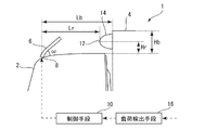
図1は本実施形態に係る車両用ディフレクタ装置を備える車両1のキャブ上部近傍を拡大して側方から示す模式図である。
車両1は、シャシ(不図示)上にキャブ2及び荷箱4が搭載されてなるトラック車両である。キャブ2は車両前方に配置されており、乗員が乗降する際に使用されるサイドドアを両側に備えている。荷箱4は、内部に貨物を収容可能な架装物であり、略直方体形状を有する。
FIG. 1 is an enlarged schematic view showing the vicinity of the upper part of a cab of a
The
ここで図1に示されるように、キャブ2上面は、荷箱4上面より低くなっており、キャブ2及び荷箱4間に段差Hbが形成されている。段差Hbは走行中、車両1が前方から受ける走行風に対して略垂直に面するため、前方からの走行風を受けることにより空気抵抗を発生させる要因となり得る。このような空気抵抗を低減させるための整流手段として、車両1はキャブ2上面に、車両前方からの走行風を整流するための可動ディフレクタ(整流板)6を備える。
Here, as shown in FIG. 1, the upper surface of the
可動ディフレクタ6は略水平なキャブ2上面に対して、車両後方に向けて所定の傾斜角度ωを有する。本実施形態では特に、可動ディフレクタ6は傾斜角度ωが可変な可動ディフレクタである。可動ディフレクタ6は不図示のアクチュエータによってキャブ2の上面との接点8を中心に回動可能に構成されており、コントロールユニットである制御手段10からの制御信号に基づいてアクチュエータを駆動することにより、可動ディフレクタ6の傾斜角度ωを任意に制御できるようになっている。
The
また車両1は、荷箱4の内部を低温に保持しながら貨物を搬送可能な冷凍車である。車両1は、荷箱4を冷却するための冷凍機(不図示)を搭載しており、図1では特に、冷凍機が有する冷凍サイクルのうち凝縮工程を構成するコンデンサユニット14が示されている。コンデンサユニット14は、冷凍サイクルを循環する冷媒との間で熱交換するための走行風を導入するための導入口12を有している。導入口12は、荷箱4のうち車両前方に面する側(すなわち段差Hb上)の上部に、導入口12が車両前方を向くように設置されている。
The
尚、コンデンサユニットは図1の符号14で示される箇所から離れた場所(例えば車体下部)に設けられていてもよく、この場合、導入口12から導入された走行風は、所定の通路(例えばダクト)を介してコンデンサユニットに導かれるように構成されていてもよい。
The capacitor unit may be provided at a location (for example, the lower part of the vehicle body) away from the location indicated by
また車両1は、車両1が備える冷凍機における冷凍負荷を検出するための負荷検出手段16を備える。ここで負荷検出手段16によって検出される冷凍負荷は、例えば冷凍機における消費電力として検出される。負荷検出手段16における検出結果は、制御手段10に送られ、後述の制御に用いられる。尚、制御手段10は、例えばECU(Electric Control Unit)のような電子演算器である。
The
続いて上記構成を有する車両1において実施される制御内容について説明する。図2は図1の制御手段10で実施される制御内容を工程毎に示すフローチャートである。制御手段10は、以下の制御方法を実施することにより、負荷検出手段16で検出された冷凍負荷に応じて可動ディフレクタ6の傾斜角度ωを制御する。
Then, the control content implemented in the
まず制御手段10は、負荷検出手段16から冷凍機における消費電力P(冷凍負荷)を取得する(ステップS1)。そして、当該取得した消費電力Pが、予め設定された閾値Pthより小さいか否かを判定する(ステップS2)。このステップでは、実測値である消費電力Pと判定基準値である閾値Pthとを比較することにより、可動ディフレクタ6の傾斜角度ωが予め設定された第1角度ω1又は第2角度ω2(<第1角度ω1)のいずれになるようにアクチュエータを制御するかが選択される。
First, the control means 10 acquires the power consumption P (refrigeration load) in the refrigerator from the load detection means 16 (step S1). Then, it is determined whether or not the acquired power consumption P is smaller than a preset threshold value Pth (step S2). In this step, the power consumption P, which is an actual measurement value, is compared with a threshold value Pth, which is a determination reference value, so that the tilt angle ω of the
消費電力Pが閾値Pthより小さい場合(ステップS2:YES)、制御手段10は、可動ディフレクタ6の傾斜角度ωが第1角度ω1となるように、アクチュエータを制御する(ステップS3)。この場合、車両前方からの走行風は、第1角度ω1を有する可動ディフレクタ6によって、図3Aに示される流路R1を形成する。この流路R1では、前方からの走行風が可動ディフレクタ6によって下流側の段差Hbに干渉することなく、荷箱上面に沿って車両後方に流れるように整流される。そのため、走行風が段差Hbにぶつかることによって生じる空気抵抗を低減できる。一方、流路R1では、走行風は導入口12を避けるように流れるため、導入口12から取り込まれる走行風が減少することによりコンデンサユニット14における熱交換効率は低下することとなるが、このケースでは冷凍負荷が比較的小さいため許容範囲となる。
When the power consumption P is smaller than the threshold value Pth (step S2: YES), the control means 10 controls the actuator so that the inclination angle ω of the
消費電力Pが閾値Pth以上である場合(ステップS2:NO)、制御手段10は、可動ディフレクタ6の傾斜角度ωが第2角度ω2となるように、アクチュエータを制御する(ステップS4)。この場合、車両前方からの走行風は、第2角度ω2を有する可動ディフレクタ6によって、図3Bに示される流路R2を形成する。この流路R2では、前方からの走行風は可動ディフレクタ6によって下流側の導入口12に導かれるように整流される。そのため、導入口12から取り込まれる走行風が増加することによりコンデンサユニット14における熱交換効率が向上し、大きな冷凍負荷に対応することができる。一方、流路R2では、走行風が段差Hbにぶつかることとなるため、図3Aの場合に比べて空気抵抗が増加することとなる。
When the power consumption P is greater than or equal to the threshold value Pth (step S2: NO), the
このようにステップS2乃至S4では、冷凍負荷である消費電力Pと閾値Pthとの大小関係に基づいて、走行風を荷箱4の上方に逃がすことによって車両1の空気抵抗の軽減を優先するか、又は、導入口12における走行風の取り込みを促すことによりコンデンサユニット14の熱交換効率を優先するか、を判断して、可動ディフレクタ6の傾斜角度ωを制御する。すなわち、冷凍負荷(消費電力)が比較的小さい場合には、コンデンサユニット14における熱交換効率も比較的低くて済むため、空気抵抗の軽減を優先するように可動ディフレクタ6の傾斜角度は第1角度ω1に制御される。一方、冷凍負荷(消費電力)が比較的大きい場合には、コンデンサユニット14の熱交換効率を向上させるため、空気抵抗が少なからず増加することを承知の上で、導入口12からの走行風の取り込みを優先するように可動ディフレクタ6の傾斜角度は第2角度ω2に制御される。
Thus, in steps S2 to S4, priority is given to reducing the air resistance of the
尚、第1角度ω1及び第2角度ω2は、車両1の仕様によって様々であるため、予め実験的、理論的又はシミュレーション的な各種手法により決定される。例えば、荷箱高さ(Hb)、可動ディフレクタ6(接点8)から荷箱4の前端までの距離(Lb)、可動ディフレクタ6(接点8)からコンデンサユニット14の前端までの距離(Lr)、キャブ2の上面に対する導入口12の高さ(Hr)、及び可動ディフレクタ6の形状等に基づいて、幾何学的に演算してもよい。
Since the first angle ω1 and the second angle ω2 vary depending on the specifications of the
尚、本実施形態では冷凍負荷が閾値を超えるか否かに基づいて第1角度ω1及び第2角度ω2の2段階に制御可能な場合について例示したが、冷凍負荷の大きさに応じてより多段階、又は、連続的に制御可能にしてもよい。この場合、例えば冷凍負荷が大きくなるに従って、導入口12から取り込まれる走行風が多くなるように(すなわち、図3Aの流路R1から図3Bの流路R2に近づくように)、傾斜角度ωが次第に減少するように制御されるとよい。逆に言えば、冷凍負荷が小さくなるに従って、段差Hbに干渉しないように車両後方に向けて整流される走行風が多くなるように(すなわち、図3Bの流路R2から図3Aの流路R1に近づくように)、傾斜角度ωが次第に増加するように制御されるとよい。このような冷凍負荷と傾斜角度ωとの関係は、予めマップとしてメモリ等の記憶手段に記憶しておき、制御手段10によって適宜参照可能に構成されていてもよい。
In this embodiment, the case where the control can be performed in two stages of the first angle ω1 and the second angle ω2 based on whether or not the refrigeration load exceeds the threshold value is illustrated. It may be controllable in stages or continuously. In this case, for example, as the refrigeration load increases, the traveling wind taken from the
以上説明したように本実施形態によれば、冷凍負荷に基づいて可動ディフレクタ6の傾斜角度ωを可変に制御することにより、冷凍機の冷凍効率を良好に確保しつつ、空気抵抗を効果的に低減可能な車両用ディフレクタ装置を実現できる。
As described above, according to the present embodiment, the air resistance is effectively improved while the refrigeration efficiency of the refrigerator is favorably secured by variably controlling the inclination angle ω of the
尚、上記実施形態では、冷凍負荷に基づいて可動ディフレクタ6を制御して走行風の流路を変更することにより、冷凍機のコンデンサユニット14への送風量を可変制御する場合を例示したが、その他のパラメータに基づいて可動ディフレクタ6の制御を行ってもよい。例えば、エンジンの排ガスに含まれる廃熱を回収するランキンサイクル回路を搭載する車両では、ランキンサイクルの稼働率に基づいて可動ディフレクタ6を制御して走行風の流路を変更することにより、ランキンサイクルに含まれるコンデンサへの送風量を可変制御してもよい。
In the above embodiment, the case where the air flow rate to the
1 車両
2 キャブ
4 荷箱
6 可動ディフレクタ
8 接点
10 制御手段
12 導入口
14 コンデンサユニット
16 負荷検出手段
Hb 段差
DESCRIPTION OF
Claims (1)
前記キャブの後方に搭載され、前方上部に冷凍機のコンデンサに走行風を導入するための導入口を有する荷箱と、
前記キャブの上面に設けられ、前記上面に対する傾斜角度を調整可能な可動ディフレクタと、
前記冷凍機の冷凍負荷を検出する負荷検出手段と、
前記可動ディフレクタの前記傾斜角度を制御する制御手段と、
を備え、
前記負荷検出手段により検出される前記冷凍負荷が所定閾値以下である場合、前記制御手段は、前記車両の走行時の空気抵抗を減少させるように前記可動ディフレクタの前記傾斜角度を制御し、前記負荷検出手段により検出される前記冷凍負荷が前記所定閾値より大きい場合、前記制御手段は、前記車両の走行時の走行風が前記導入口に導入されるように可動ディフレクタの前記傾斜角度を制御する車両用ディフレクタ装置。
With the cab,
A cargo box mounted on the rear of the cab and having an inlet for introducing a running wind into the condenser of the refrigerator at the front upper part;
A movable deflector provided on an upper surface of the cab and capable of adjusting an inclination angle with respect to the upper surface;
Load detecting means for detecting a refrigeration load of the refrigerator;
Control means for controlling the tilt angle of the movable deflector;
With
When the refrigeration load detected by the load detection means is less than or equal to a predetermined threshold, the control means controls the inclination angle of the movable deflector so as to reduce the air resistance during travel of the vehicle, and the load When the refrigeration load detected by the detection unit is larger than the predetermined threshold, the control unit controls the inclination angle of the movable deflector so that the traveling wind during traveling of the vehicle is introduced into the introduction port. Deflector device.
Priority Applications (1)
| Application Number | Priority Date | Filing Date | Title |
|---|---|---|---|
| JP2016090686A JP2017197065A (en) | 2016-04-28 | 2016-04-28 | Vehicular deflector device |
Applications Claiming Priority (1)
| Application Number | Priority Date | Filing Date | Title |
|---|---|---|---|
| JP2016090686A JP2017197065A (en) | 2016-04-28 | 2016-04-28 | Vehicular deflector device |
Publications (1)
| Publication Number | Publication Date |
|---|---|
| JP2017197065A true JP2017197065A (en) | 2017-11-02 |
Family
ID=60238760
Family Applications (1)
| Application Number | Title | Priority Date | Filing Date |
|---|---|---|---|
| JP2016090686A Pending JP2017197065A (en) | 2016-04-28 | 2016-04-28 | Vehicular deflector device |
Country Status (1)
| Country | Link |
|---|---|
| JP (1) | JP2017197065A (en) |
Cited By (1)
| Publication number | Priority date | Publication date | Assignee | Title |
|---|---|---|---|---|
| WO2019059374A1 (en) * | 2017-09-25 | 2019-03-28 | 三菱重工サーマルシステムズ株式会社 | Transportation refrigeration unit |
-
2016
- 2016-04-28 JP JP2016090686A patent/JP2017197065A/en active Pending
Cited By (1)
| Publication number | Priority date | Publication date | Assignee | Title |
|---|---|---|---|---|
| WO2019059374A1 (en) * | 2017-09-25 | 2019-03-28 | 三菱重工サーマルシステムズ株式会社 | Transportation refrigeration unit |
Similar Documents
| Publication | Publication Date | Title |
|---|---|---|
| JP4385678B2 (en) | Battery cooling system for vehicles | |
| JP4438757B2 (en) | Vehicle cooling system | |
| EP1787838A1 (en) | Vehicle air conditioning system | |
| JP4614688B2 (en) | A cooling system and a hybrid vehicle equipped with it. | |
| US9212838B2 (en) | Cooling device for vehicles and method for controlling and/or regulating a cooling device | |
| JP5073389B2 (en) | Air conditioning control device for vehicles | |
| JP2010206957A (en) | Battery cooling system for vehicle | |
| US9868336B2 (en) | Method and system for controlling condenser/radiator airflow | |
| US20140290599A1 (en) | Active grille shutter | |
| WO2014106063A1 (en) | Method and system for controlling operation of condenser and evaporator fans | |
| JP6706556B2 (en) | Vehicle air conditioner | |
| JP5012491B2 (en) | Control device for vehicle air conditioner and vehicle | |
| JP3876762B2 (en) | Air conditioner for vehicles | |
| CN105377600A (en) | Vehicular air conditioning device | |
| JP2006327453A (en) | Air conditioner control device for vehicle | |
| CN108422920B (en) | Heat dissipation system for mobile charging vehicle, mobile charging vehicle and control method of mobile charging vehicle | |
| JP2017197065A (en) | Vehicular deflector device | |
| JP4506825B2 (en) | Air conditioner for vehicles | |
| JP5772646B2 (en) | Air conditioner for vehicles | |
| JP2006218920A (en) | Air-conditioning control device for vehicle | |
| JP2015137032A (en) | vehicle | |
| JP2007253901A (en) | Vehicular air conditioner | |
| JP2013113561A (en) | Cooling storage device for vehicle | |
| JP2020182286A (en) | Battery cooling device | |
| JP2015107694A (en) | Air conditioning controller for vehicle |