JP2017194299A - Coat soundness evaluation method - Google Patents
Coat soundness evaluation method Download PDFInfo
- Publication number
- JP2017194299A JP2017194299A JP2016083196A JP2016083196A JP2017194299A JP 2017194299 A JP2017194299 A JP 2017194299A JP 2016083196 A JP2016083196 A JP 2016083196A JP 2016083196 A JP2016083196 A JP 2016083196A JP 2017194299 A JP2017194299 A JP 2017194299A
- Authority
- JP
- Japan
- Prior art keywords
- coating
- reflected wave
- coat
- evaluation method
- adhesion
- Prior art date
- Legal status (The legal status is an assumption and is not a legal conclusion. Google has not performed a legal analysis and makes no representation as to the accuracy of the status listed.)
- Granted
Links
Images


Landscapes
- Length Measuring Devices Characterised By Use Of Acoustic Means (AREA)
- Investigating Or Analyzing Materials By The Use Of Ultrasonic Waves (AREA)
Abstract
Description
本発明は被膜健全性評価方法に関する。 The present invention relates to a coating soundness evaluation method.
例えば、鋼管の内面に防食塗膜を塗装してなる配管は、その防食塗膜が鋼管に密着していることが必要であるものの、継続して使用していれば継時的に防食塗膜が劣化し、その密着の程度が必ず低下していく。
ここで、防食塗膜が剥がれてしまっては配管に不具合が生じる可能性があるため、定期的に検査することで防食被膜の鋼管への密着度合いを把握し、必要に応じて、補修することが重要である。
また、防食塗膜の鋼管への密着度合いの劣化の程度を予測し、補修すべき時期を予め知ることができれば、定修時のスケジュールを組みやすいという点で好ましい。
For example, a pipe made by coating a steel pipe with an anticorrosive coating on the inner surface of the pipe requires that the anticorrosive coating is in close contact with the steel pipe. Will deteriorate and the degree of adhesion will inevitably decrease.
Here, if the anti-corrosion coating is peeled off, there is a possibility that the piping may malfunction, so check the degree of adhesion of the anti-corrosion coating to the steel pipe by regular inspection, and repair as necessary. is important.
Moreover, if the degree of deterioration of the degree of adhesion of the anticorrosive coating film to the steel pipe can be predicted and the time for repairing can be known in advance, it is preferable in that it is easy to set a schedule for regular repairs.
上記のような内面の防食塗膜の配管への密着度合いの程度の把握は、配管の外部から行う必要がある。使用時において配管はその内部にガスや水などが流れているからである。 It is necessary to grasp the degree of adhesion of the anticorrosion coating on the inner surface to the pipe as described above from the outside of the pipe. This is because gas or water flows through the piping during use.
本発明の目的は、部材の内面に被膜が付いてなる構造物において、鋼管等の部材の内面に付いている被膜の前記部材へ密着の程度を、外側からの測定によって把握することができ、定期的に測定すれば被膜の劣化予測を行うことができる、被膜健全性評価方法を提供することである。 The object of the present invention is a structure in which a coating is attached to the inner surface of a member, and the degree of adhesion of the coating attached to the inner surface of a member such as a steel pipe can be grasped by measurement from the outside, It is to provide a coating soundness evaluation method capable of predicting the deterioration of the coating if measured periodically.
本発明者は鋭意検討し、上記課題を解決する方法を見出して本発明を完成させた。
本発明は次の(1)〜(3)である。
(1)部材の内面Aに被膜が付いている構造物における、前記被膜の前記内面Aへの密着度合いを外面から求め、評価する、被膜健全性評価方法であって、
前記部材の外面Bから前記内面Aへ超音波パルスを入射する入射工程と、
前記部材の前記内面Aと前記被膜の外面Dとの界面αで反射する第1反射波を受信する受信工程[1]と、
前記第1反射波および前記構造物の内部と前記被膜の内面Cとの界面βで反射する第2反射波の合成反射波を受信する受信工程[2]と、
前記第1反射波に対する前記第2反射波の強度の比を算出し、この比から前記被膜の前記外面Dの前記内面Aへの密着度合いを求め、評価する評価工程と、
を備える、被膜健全性評価方法。
(2)前記部材が鋼材であり、前記被膜が有機物を主成分とする防食塗膜である、上記(1)に記載の被膜健全性評価方法。
(3)前記部材が鋼管であり、その内部に気体、液体および固体からなる群から選ばれる少なくとも1つが流動しているときに行う、上記(1)または(2)に記載の被膜健全性評価方法。
The inventor diligently studied and found a method for solving the above-mentioned problems, and completed the present invention.
The present invention includes the following (1) to (3).
(1) In a structure having a coating on the inner surface A of a member, a coating soundness evaluation method for obtaining and evaluating the degree of adhesion of the coating to the inner surface A from the outer surface,
An incident step of injecting an ultrasonic pulse from the outer surface B of the member to the inner surface A;
A receiving step [1] for receiving a first reflected wave reflected at the interface α between the inner surface A of the member and the outer surface D of the coating;
A receiving step [2] for receiving the first reflected wave and the combined reflected wave of the second reflected wave reflected at the interface β between the inside of the structure and the inner surface C of the coating;
Calculating a ratio of the intensity of the second reflected wave to the first reflected wave, obtaining an evaluation of the degree of adhesion of the coating to the inner surface A of the outer surface D from the ratio,
A method for evaluating film soundness.
(2) The coating soundness evaluation method according to the above (1), wherein the member is a steel material, and the coating is an anticorrosion coating containing an organic substance as a main component.
(3) The coating soundness evaluation according to (1) or (2), which is performed when the member is a steel pipe and at least one selected from the group consisting of a gas, a liquid, and a solid is flowing therein. Method.
本発明によれば、部材の内面に被膜が付いてなる構造物において、鋼管等の部材の内面に付いている被膜の前記部材へ密着の程度を、外側からの測定によって把握することができ、定期的に測定すれば被膜の劣化予測を行うことができる、被膜健全性評価方法を提供することができる。 According to the present invention, in a structure having a coating on the inner surface of a member, the degree of adhesion to the member of the coating on the inner surface of a member such as a steel pipe can be grasped by measurement from the outside, It is possible to provide a coating soundness evaluation method capable of predicting the deterioration of the coating if measured periodically.
本発明の被膜健全性評価方法(以下、単に「本発明の評価方法」ともいう)について、図を用いて説明する。
図1は本発明の評価方法における構造物に該当する配管10の断面一部拡大図である。図1において配管10(構造物)は、鋼管12(部材)の内面に被膜14が付いてなるものとする。
The film soundness evaluation method of the present invention (hereinafter also simply referred to as “the evaluation method of the present invention”) will be described with reference to the drawings.
FIG. 1 is a partially enlarged cross-sectional view of a
本発明の評価方法は、鋼管12の内面Aに被膜14が付いている配管10における、被膜14の内面Aへの密着度合いを外面Bから求め、評価する、被膜健全性評価方法であって、鋼管12の外面Bから内面Aへ超音波パルスを入射する入射工程と、鋼管12の内面Aと被膜14の外面Dとの界面αで反射する第1反射波P1を受信する受信工程[1]と、第1反射波P1および配管10の内部(図1では液体W)と被膜14の内面Cとの界面βで反射する第2反射波P2の合成反射波Pmを受信する受信工程[2]と、第1反射波P1に対する第2反射波P2の強度の比を算出し、この比から被膜14の外面Dの内面Aへの密着度合いを求め、評価する評価工程と、を備える、被膜健全性評価方法である。
The evaluation method of the present invention is a coating soundness evaluation method for obtaining and evaluating the degree of adhesion to the inner surface A of the
本発明の評価方法は、例えば図2に示す測定装置を用いて実施することができる。
図2は、本発明の評価方法を実施することができる測定装置の概略図である。
測定装置1は、パーソナルコンピューター7により制御されるパルサー2aで超音波パルスを発生し、探触子3を介して配管10の外面Bから配管10の中心に向かって垂直に超音波パルスを送信する(入射工程)。
送信された超音波パルスは、まず鋼管12の内面Aと被膜14の外面Dとの界面αにおいて反射し、第1反射波P1として探触子3側に復帰する(受信工程[1])。
また、送信された超音波パルスは配管10の内部(図1に示す場合は水W)と被膜14の内面Cとの界面βにおいて反射し、第2反射波P2として探触子3側に復帰する。ここで第2反射波P2は第1反射波P1と合成された合成反射波として、探触子3側で受信される(受信工程[2])。
The evaluation method of the present invention can be implemented using, for example, the measuring apparatus shown in FIG.
FIG. 2 is a schematic view of a measuring apparatus that can carry out the evaluation method of the present invention.
The
The transmitted ultrasonic pulse is first reflected at the interface α between the inner surface A of the
The ultrasonic pulses transmitted is (the case shown in FIG. 1 water W) inside the
これらの第1反射波P1、第2反射波P2は、レシーバー2bおよびプリアンプ4により増幅され、フィルター5によりノイズが除去された状態でA/Dコンバーター6によりデジタル信号に変換され、パーソナルコンピューター7で処理される。第1反射波P1、第2反射波P2はレシーバー2bにて補足され、モニター8に表示される。ここで正確には、第2反射波P2は第1反射波P1との合成反射波Pmとして補足され、モニター8に表示される。
The first reflected wave P 1 and the second reflected wave P 2 are amplified by the receiver 2 b and the preamplifier 4, converted into a digital signal by the A / D converter 6 with the noise removed by the
例えば図2に示した測定装置を用いて図1に示した配管10について、本発明の評価方法を適用すると、図3、図4に示すようなデータが得られる。
For example, when the evaluation method of the present invention is applied to the
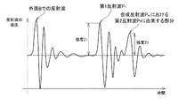
ここで図3は、被膜14の外面Dが鋼管12の内面Aと健全に密着している場合に得られるデータの例を示している。横軸(X軸)が時間、縦軸(Y軸)は反射波の強度を示している。
探触子3を介して配管10の外面Bから配管10の中心に向かって垂直に超音波パルスを送信すると、送信された超音波パルスは、初めに鋼管12の外面Bで反射するので、その反射波が受信される。次に、鋼管12の内面Aと被膜14の外面Dとの界面αにおいて反射し、第1反射波P1として探触子3側で受信される。ここで受信した第1反射波P1の強度を強度Z1とする。
次に、送信された超音波パルスは配管10の内部(図1に示す場合は水W)と被膜14の内面Cとの界面βにおいて反射し、第2反射波P2として探触子3側で受信される。ここで第2反射波P2は第1反射波P1と合成された合成反射波Pmとして、探触子3側で受信されるが、図3に示すように、その合成反射波における第2反射波P2に由来する部分が確認できる。ここで受信した第2反射波P2の強度を強度Z2とする。なお、ここで得られる第2反射波P2およびその強度は、正確には、合成反射波Pmにおける第2反射波P2に由来する部分およびその強度を意味しているが、本明細書ではそれらを区別せずに記載している場合がある。
Here, FIG. 3 shows an example of data obtained when the outer surface D of the
When an ultrasonic pulse is transmitted vertically from the outer surface B of the
Next, an ultrasonic pulse transmitted is (the case shown in FIG. 1 water W) inside the
そして、本発明者は、外面Dと内面Aとの密着の度合いと、強度Z2/強度Z1との間に正の相関があることを見出した。つまり、外面Dと内面Aとの密着の度合いが高いと強度Z2/強度Z1の値も高くなることを見出した。また、この値を定期的に測定すれば被膜の劣化を予測することができることを、本発明者は見出した。 The inventor has found that there is a positive correlation between the degree of adhesion between the outer surface D and the inner surface A and the strength Z 2 / strength Z 1 . That is, it has been found that the strength Z 2 / strength Z 1 increases as the degree of adhesion between the outer surface D and the inner surface A increases. Further, the present inventor has found that the deterioration of the film can be predicted by periodically measuring this value.
ここで、外面Dと内面Aとの密着の度合いが低く、例えば、外面Dと内面Aとが全く接触していない場合、図4に示すようなデータが得られる。
すなわち、探触子3を介して配管10の外面Bから配管10の中心に向かって垂直に超音波パルスを送信すると、送信された超音波パルスは、初めに鋼管12の外面Bで反射するので、その反射波が受信され、次に、鋼管12の内面Aと被膜14の外面Dとの界面αにおいて反射し、第1反射波P1として探触子3側で受信されるが、第2反射波P2に相当する部分が確認できないデータである。
この場合、強度Z2/強度Z1の値はゼロということなる。
Here, when the degree of close contact between the outer surface D and the inner surface A is low, for example, when the outer surface D and the inner surface A are not in contact at all, data as shown in FIG. 4 is obtained.
That is, when an ultrasonic pulse is transmitted vertically from the outer surface B of the
In this case, the value of strength Z 2 / strength Z 1 is zero.
強度Z2/強度Z1と内面塗膜密着力の保持率との関係を示すと、例えば図5に示すような正の相関図が得られることを、本発明者は見出した。
強度Z2/強度Z1と内面塗膜密着力の保持率との関係は、対象物(構造物)の種類等によって異なるが、例えば、強度Z2/強度Z1×100で30%程度のあると、内面塗膜密着力の保持率が90%程度であることが多い。この場合、保持率が高いので補修する必要はない。強度Z2/強度Z1×100で10%程度のあると、内面塗膜密着力の保持率が30%程度であることが多い。この場合、保持率が低いので補修する必要がある。強度Z2/強度Z1×100の値を定期的に測定してれば、将来において、例えば強度Z2/強度Z1×100が10%程度にある時期を予測できる。すなわち、上記のような方法で、鋼管等の構造物の内部の被膜が構造物に密着している程度を定期的に測定することで図5に示すグラフを得ることができれば、被膜の劣化予測を行うことができる。このような予測を得ることができれば、適切な補修タイミングを知り、工場の定修日等を考慮した補修スケジュールを立てることができるので、極めて有効である。
The present inventor has found that, for example, a positive correlation diagram as shown in FIG. 5 is obtained when the relationship between the strength Z 2 / strength Z 1 and the retention ratio of the inner surface coating film adhesion is shown.
The relationship between the strength Z 2 / strength Z 1 and the retention rate of the inner surface coating film adhesion varies depending on the type of the object (structure), etc., but for example, the strength Z 2 / strength Z 1 × 100 is about 30%. If so, the retention rate of the inner surface coating film adhesion is often about 90%. In this case, it is not necessary to repair because the retention rate is high. When the strength Z 2 / strength Z 1 × 100 is about 10%, the retention rate of the inner surface coating film adhesion is often about 30%. In this case, since the retention rate is low, repair is necessary. If the value of strength Z 2 / strength Z 1 × 100 is regularly measured, it is possible to predict the time when, for example, strength Z 2 / strength Z 1 × 100 is about 10% in the future. That is, if the graph shown in FIG. 5 can be obtained by periodically measuring the degree of adhesion of the coating inside the structure such as a steel pipe to the structure by the above-described method, the deterioration of the coating can be predicted. It can be performed. If such a prediction can be obtained, it is extremely effective because it is possible to know an appropriate repair timing and to establish a repair schedule in consideration of the regular repair date of the factory.
本発明の評価方法は、部材の内面Aに被膜が付いている構造物を対象とする。
このような構造物に該当するものとして、例えば、内部に防食塗膜が付いているガス配管、蒸気配管、水や石油等が流れる配管が挙げられる。このような配管は製鉄所内、火力発電所内、石油精製コンビナート内で利用されており、使用を継続すれば時間の経過と共に被膜が劣化し、その密着の程度が低下するので、防食被膜の配管への密着度合いを把握し、その密着度合いによって、剥がれる前に補修することが重要である。また、通常、このような配管内にはガス、水、石油などが流れているため、配管の外部から内部の被膜の状態を把握する必要がある。
構造物として、他にも、タンクや圧力容器が挙げられる。
The evaluation method of the present invention is directed to a structure having a coating on the inner surface A of the member.
Examples of such structures include gas pipes, steam pipes, and pipes through which water, oil, etc. flow with anticorrosion coatings inside. Such pipes are used in steelworks, thermal power plants, and oil refineries, and if they are used continuously, the coating will deteriorate over time and the degree of adhesion will decrease. It is important to grasp the degree of adhesion of the material and repair it before peeling off according to the degree of adhesion. Further, since gas, water, oil, and the like normally flow in such a pipe, it is necessary to grasp the state of the internal coating from the outside of the pipe.
Other structures include tanks and pressure vessels.
部材の厚さ(図1の場合であれば鋼管12の厚さが相当する)は特に限定されず、例えば3mm〜20mmの範囲のものに好ましく適用することができる。
The thickness of the member (in the case of FIG. 1, the thickness of the
本発明の評価方法において被膜は特に限定されないが、有機物を主成分(概ね70質量%以上含むことを意味するものとする)とする防食塗膜であることが好ましい。このような防食塗膜としてエポキシ樹脂やウレタン樹脂等からなるものや、さらにこれらの有機樹脂に亜鉛粉末を含んだものが例示される。
皮膜の厚さは特に限定されず、例えば10μm〜5,000μmの範囲のものに好ましく適用することができる。
In the evaluation method of the present invention, the coating film is not particularly limited, but is preferably an anticorrosion coating film containing an organic substance as a main component (meaning that it contains approximately 70% by mass or more). Examples of such anticorrosive coatings include those composed of epoxy resins, urethane resins, etc., and those containing these powders containing zinc powder.
The thickness of the film is not particularly limited, and can be preferably applied to a film in the range of 10 μm to 5,000 μm, for example.
なお、本発明の評価方法の入射工程において用いる超音波パルスは、超音波であることが好ましいが、超音波に近い波長を有する音波等であってよい。 The ultrasonic pulse used in the incident step of the evaluation method of the present invention is preferably an ultrasonic wave, but may be a sound wave having a wavelength close to the ultrasonic wave.
Claims (3)
前記部材の外面Bから前記内面Aへ超音波パルスを入射する入射工程と、
前記部材の前記内面Aと前記被膜の外面Dとの界面αで反射する第1反射波を受信する受信工程[1]と、
前記第1反射波および前記構造物の内部と前記被膜の内面Cとの界面βで反射する第2反射波の合成反射波を受信する受信工程[2]と、
前記第1反射波に対する前記第2反射波の強度の比を算出し、この比から前記被膜の前記外面Dの前記内面Aへの密着度合いを求め、評価する評価工程と、
を備える、被膜健全性評価方法。 In a structure with a coating on the inner surface A of a member, the degree of adhesion to the inner surface A of the coating is determined from the outer surface and evaluated,
An incident step of injecting an ultrasonic pulse from the outer surface B of the member to the inner surface A;
A receiving step [1] for receiving a first reflected wave reflected at the interface α between the inner surface A of the member and the outer surface D of the coating;
A receiving step [2] for receiving the first reflected wave and the combined reflected wave of the second reflected wave reflected at the interface β between the inside of the structure and the inner surface C of the coating;
Calculating a ratio of the intensity of the second reflected wave to the first reflected wave, obtaining an evaluation of the degree of adhesion of the coating to the inner surface A of the outer surface D from the ratio,
A method for evaluating film soundness.
Priority Applications (1)
| Application Number | Priority Date | Filing Date | Title |
|---|---|---|---|
| JP2016083196A JP6804863B2 (en) | 2016-04-18 | 2016-04-18 | Film soundness evaluation method |
Applications Claiming Priority (1)
| Application Number | Priority Date | Filing Date | Title |
|---|---|---|---|
| JP2016083196A JP6804863B2 (en) | 2016-04-18 | 2016-04-18 | Film soundness evaluation method |
Publications (2)
| Publication Number | Publication Date |
|---|---|
| JP2017194299A true JP2017194299A (en) | 2017-10-26 |
| JP6804863B2 JP6804863B2 (en) | 2020-12-23 |
Family
ID=60155366
Family Applications (1)
| Application Number | Title | Priority Date | Filing Date |
|---|---|---|---|
| JP2016083196A Active JP6804863B2 (en) | 2016-04-18 | 2016-04-18 | Film soundness evaluation method |
Country Status (1)
| Country | Link |
|---|---|
| JP (1) | JP6804863B2 (en) |
Citations (8)
| Publication number | Priority date | Publication date | Assignee | Title |
|---|---|---|---|---|
| US4446736A (en) * | 1980-10-10 | 1984-05-08 | Imperial Chemical Industries Plc | Ultrasonic identification of damage in lined structures |
| JPH10153585A (en) * | 1996-11-25 | 1998-06-09 | Hitachi Ltd | Surface layer evaluating method and apparatus therefor |
| JP2000329751A (en) * | 1999-05-18 | 2000-11-30 | Toshiba Corp | Method and apparatus for inspection of piping |
| JP2003004711A (en) * | 2001-06-20 | 2003-01-08 | Hitachi Ltd | Method for inspecting concrete structure and inspection device using the same |
| JP2003130854A (en) * | 2001-10-22 | 2003-05-08 | Chubu Electric Power Co Inc | Pipe arrangement examining method and device |
| JP2004226123A (en) * | 2003-01-20 | 2004-08-12 | Shikoku Electric Power Co Inc | Inspection device for fluid conveying pipe |
| JP2009258072A (en) * | 2008-03-19 | 2009-11-05 | Tokyo Electric Power Co Inc:The | Method and apparatus for piping inspection |
| JP2013083545A (en) * | 2011-10-11 | 2013-05-09 | Central Research Institute Of Electric Power Industry | Method and apparatus for detecting boundary surface states of multilayer pipeline by ultrasonic attenuation method |
-
2016
- 2016-04-18 JP JP2016083196A patent/JP6804863B2/en active Active
Patent Citations (8)
| Publication number | Priority date | Publication date | Assignee | Title |
|---|---|---|---|---|
| US4446736A (en) * | 1980-10-10 | 1984-05-08 | Imperial Chemical Industries Plc | Ultrasonic identification of damage in lined structures |
| JPH10153585A (en) * | 1996-11-25 | 1998-06-09 | Hitachi Ltd | Surface layer evaluating method and apparatus therefor |
| JP2000329751A (en) * | 1999-05-18 | 2000-11-30 | Toshiba Corp | Method and apparatus for inspection of piping |
| JP2003004711A (en) * | 2001-06-20 | 2003-01-08 | Hitachi Ltd | Method for inspecting concrete structure and inspection device using the same |
| JP2003130854A (en) * | 2001-10-22 | 2003-05-08 | Chubu Electric Power Co Inc | Pipe arrangement examining method and device |
| JP2004226123A (en) * | 2003-01-20 | 2004-08-12 | Shikoku Electric Power Co Inc | Inspection device for fluid conveying pipe |
| JP2009258072A (en) * | 2008-03-19 | 2009-11-05 | Tokyo Electric Power Co Inc:The | Method and apparatus for piping inspection |
| JP2013083545A (en) * | 2011-10-11 | 2013-05-09 | Central Research Institute Of Electric Power Industry | Method and apparatus for detecting boundary surface states of multilayer pipeline by ultrasonic attenuation method |
Also Published As
| Publication number | Publication date |
|---|---|
| JP6804863B2 (en) | 2020-12-23 |
Similar Documents
| Publication | Publication Date | Title |
|---|---|---|
| Honarvar et al. | Ultrasonic monitoring of erosion/corrosion thinning rates in industrial piping systems | |
| JP5624250B2 (en) | Lamination peel test method and peel inspection apparatus | |
| US10345221B1 (en) | Ultrasonic corrosion coupon probe | |
| US10107658B2 (en) | Ultrasonic flowmeter with internal surface coating and method | |
| US10585069B2 (en) | Detection, monitoring, and determination of location of changes in metallic structures using multimode acoustic signals | |
| CN102203585A (en) | Inspection method for inspecting corrosion under insulation | |
| Wang et al. | Numerical and analytical study for ultrasonic testing of internal delamination defects considering surface roughness | |
| Farin et al. | Monitoring saltwater corrosion of steel using ultrasonic coda wave interferometry with temperature control | |
| US20120265450A1 (en) | Method for inspecting corrosion under insulation | |
| JP2003130854A (en) | Pipe arrangement examining method and device | |
| JP2006276032A (en) | Method and system for pipe testing | |
| RU2613624C1 (en) | Method for nondestructive ultrasonic inspection of water conduits of hydraulic engineering facilities | |
| JP2017194299A (en) | Coat soundness evaluation method | |
| Kulkov et al. | Automated quality control systems for paint coatings in industry | |
| Dhutti et al. | Monitoring of critical metallic assets in oil and gas industry using ultrasonic guided waves | |
| Heerings et al. | Inspection Effectiveness and its Effect on the Integrity of Pipework | |
| Saifullin et al. | Methods of Leak Search from Pipeline for Acoustic Signal Analysis | |
| Rahman et al. | A review of ultrasonic tomography for monitoring the corrosion of steel pipes | |
| Bertoncini et al. | 3D characterization of defects in Guided Wave monitoring of pipework using a magnetostrictive sensor | |
| Gunarathna et al. | Challenges in Monitoring Metallic Pipeline Corrosion Using Ultrasonic Waves—A Review Article | |
| Stepinski | Structural health monitoring of piping in nuclear power plants-A review of efficiency of existing methods | |
| Riahi et al. | Health monitoring of aboveground storage tanks’ floors: A new methodology based on practical experience | |
| Ficquet et al. | Structural health monitoring on a girth welded pipe with residual stress measurements | |
| Schubert et al. | Monitoring of high temperature steel pipes by ultrasonic waveguide solutions | |
| RU2626744C1 (en) | Intratubal ultrasonic flaw detector |
Legal Events
| Date | Code | Title | Description |
|---|---|---|---|
| A621 | Written request for application examination |
Free format text: JAPANESE INTERMEDIATE CODE: A621 Effective date: 20190123 |
|
| A977 | Report on retrieval |
Free format text: JAPANESE INTERMEDIATE CODE: A971007 Effective date: 20191009 |
|
| A131 | Notification of reasons for refusal |
Free format text: JAPANESE INTERMEDIATE CODE: A131 Effective date: 20191023 |
|
| A521 | Request for written amendment filed |
Free format text: JAPANESE INTERMEDIATE CODE: A523 Effective date: 20191211 |
|
| A131 | Notification of reasons for refusal |
Free format text: JAPANESE INTERMEDIATE CODE: A131 Effective date: 20200512 |
|
| A521 | Request for written amendment filed |
Free format text: JAPANESE INTERMEDIATE CODE: A523 Effective date: 20200616 |
|
| TRDD | Decision of grant or rejection written | ||
| A01 | Written decision to grant a patent or to grant a registration (utility model) |
Free format text: JAPANESE INTERMEDIATE CODE: A01 Effective date: 20201124 |
|
| A61 | First payment of annual fees (during grant procedure) |
Free format text: JAPANESE INTERMEDIATE CODE: A61 Effective date: 20201203 |
|
| R150 | Certificate of patent or registration of utility model |
Ref document number: 6804863 Country of ref document: JP Free format text: JAPANESE INTERMEDIATE CODE: R150 |
|
| R250 | Receipt of annual fees |
Free format text: JAPANESE INTERMEDIATE CODE: R250 |