JP2017194013A - Fuel gas supply system and fuel gas supply method - Google Patents
Fuel gas supply system and fuel gas supply method Download PDFInfo
- Publication number
- JP2017194013A JP2017194013A JP2016084905A JP2016084905A JP2017194013A JP 2017194013 A JP2017194013 A JP 2017194013A JP 2016084905 A JP2016084905 A JP 2016084905A JP 2016084905 A JP2016084905 A JP 2016084905A JP 2017194013 A JP2017194013 A JP 2017194013A
- Authority
- JP
- Japan
- Prior art keywords
- gas
- fuel gas
- compression mechanism
- temperature
- fuel
- Prior art date
- Legal status (The legal status is an assumption and is not a legal conclusion. Google has not performed a legal analysis and makes no representation as to the accuracy of the status listed.)
- Granted
Links
Images


Classifications
-
- Y—GENERAL TAGGING OF NEW TECHNOLOGICAL DEVELOPMENTS; GENERAL TAGGING OF CROSS-SECTIONAL TECHNOLOGIES SPANNING OVER SEVERAL SECTIONS OF THE IPC; TECHNICAL SUBJECTS COVERED BY FORMER USPC CROSS-REFERENCE ART COLLECTIONS [XRACs] AND DIGESTS
- Y02—TECHNOLOGIES OR APPLICATIONS FOR MITIGATION OR ADAPTATION AGAINST CLIMATE CHANGE
- Y02T—CLIMATE CHANGE MITIGATION TECHNOLOGIES RELATED TO TRANSPORTATION
- Y02T10/00—Road transport of goods or passengers
- Y02T10/10—Internal combustion engine [ICE] based vehicles
- Y02T10/30—Use of alternative fuels, e.g. biofuels
-
- Y—GENERAL TAGGING OF NEW TECHNOLOGICAL DEVELOPMENTS; GENERAL TAGGING OF CROSS-SECTIONAL TECHNOLOGIES SPANNING OVER SEVERAL SECTIONS OF THE IPC; TECHNICAL SUBJECTS COVERED BY FORMER USPC CROSS-REFERENCE ART COLLECTIONS [XRACs] AND DIGESTS
- Y02—TECHNOLOGIES OR APPLICATIONS FOR MITIGATION OR ADAPTATION AGAINST CLIMATE CHANGE
- Y02T—CLIMATE CHANGE MITIGATION TECHNOLOGIES RELATED TO TRANSPORTATION
- Y02T70/00—Maritime or waterways transport
- Y02T70/50—Measures to reduce greenhouse gas emissions related to the propulsion system
- Y02T70/5218—Less carbon-intensive fuels, e.g. natural gas, biofuels
Landscapes
- Output Control And Ontrol Of Special Type Engine (AREA)
Abstract
【課題】推進エンジンの運転負荷が急激に変化しても、安定した燃料ガスの供給を実現する。さらに、天然ガスとは異なる種類の燃料ガスでも、安定した燃料ガスの供給を実現する。【解決手段】推進エンジンに燃料ガスを供給するために、前記燃料ガスを圧縮して前記推進エンジンの側に流す、直列に設けられた複数のガス圧縮機構を備え、前記ガス圧縮機構のそれぞれは、ガスコンプレッサと、吸引スナッバ及び吐出スナッバと、前記吐出スナッバより下流側に設けられた熱交換器と、を備える。前記複数のガス圧縮機構のうちの第1ガス圧縮機構は、前記第1ガス圧縮機構の熱交換器のガス出力端と、前記第1ガス圧縮機構のガスコンプレッサよりも前記流れ方向の上流側に設けられた別のガス圧縮機構のガスコンプレッサの吐出スナッバとを、前記第1ガス圧縮機構のガスコンプレッサを経由することなく繋ぐ第1バイパス管を備える。【選択図】 図1A stable supply of fuel gas is realized even when the operating load of a propulsion engine changes abruptly. Furthermore, a stable supply of fuel gas can be realized even with a different type of fuel gas from natural gas. In order to supply fuel gas to a propulsion engine, a plurality of gas compression mechanisms provided in series for compressing and flowing the fuel gas to the propulsion engine side are provided, each of the gas compression mechanisms being A gas compressor, a suction snubber and a discharge snubber, and a heat exchanger provided on the downstream side of the discharge snubber. The first gas compression mechanism of the plurality of gas compression mechanisms is disposed upstream of the gas output end of the heat exchanger of the first gas compression mechanism and the gas compressor of the first gas compression mechanism in the flow direction. A first bypass pipe is provided that connects a discharge snubber of a gas compressor of another gas compression mechanism provided without passing through the gas compressor of the first gas compression mechanism. [Selection] Figure 1
Description
本発明は、船舶の推進エンジンに圧縮した燃料ガスを供給する燃料ガス供給システム及び燃料ガス供給方法に関する。 The present invention relates to a fuel gas supply system and a fuel gas supply method for supplying compressed fuel gas to a propulsion engine of a ship.
近年、メタンを主成分とした天然ガスを燃料ガスとして船舶の推進エンジンに供給する燃料ガス供給装置が種々提案されている。例えば、LNGを運搬する際、LNGから自然気化するボイルオフガスは再液化されてLNGとして運搬するだけでなく、ボイルオフガスは船舶の推進エンジンの燃料ガスとして有効に用いられる。例えば、LNGを運搬するLNG運搬船において、LNGの運搬中に発生するボイルオフガスは所定の圧力に加圧して、燃料ガスとして推進エンジンに供給される。 In recent years, various fuel gas supply devices that supply natural gas mainly composed of methane to a propulsion engine of a ship as fuel gas have been proposed. For example, when transporting LNG, boil-off gas that naturally vaporizes from LNG is not only re-liquefied and transported as LNG, but the boil-off gas is effectively used as a fuel gas for a marine propulsion engine. For example, in an LNG carrier that transports LNG, boil-off gas generated during the transportation of LNG is pressurized to a predetermined pressure and supplied to the propulsion engine as fuel gas.
ボイルオフガスのような低圧のガスを高圧のガスとするには、多段圧縮機を用いてガスを圧縮することが行われる。多段圧縮機は、例えば直列接続された複数の圧縮機からなる(特許文献1)。
さらに、燃料ガスを多段の圧縮機を用いて約30MPaまで加圧して、エンジン(MC−GIエンジン)のガス噴射弁に供給することも知られている(非特許文献1)。
In order to convert a low-pressure gas such as boil-off gas into a high-pressure gas, the gas is compressed using a multistage compressor. A multistage compressor consists of several compressors connected in series, for example (patent document 1).
Furthermore, it is also known that fuel gas is pressurized to about 30 MPa using a multistage compressor and supplied to a gas injection valve of an engine (MC-GI engine) (Non-patent Document 1).
上述の多段の圧縮機を用いて燃料ガスを約30MPaまで加圧してガス噴射弁に供給するエンジン(MC−GIエンジン)は、陸上発電用エンジンであり、基本的に略一定負荷の運転を前提とした低速ディーゼルエンジンであり、多段のガスコンプレッサも略一定圧力の燃料ガスを供給すればよい。
一方、このような多段の圧縮機(ガスコンプレッサ)を船舶推進用の低速ディーゼルエンジンに適用した場合、このエンジンの負荷は急速に変化するため、多段の圧縮機(ガスコンプレッサ)の運転も急激に変化する必要がある。例えば、操船による減速、加速、旋回によって、あるいは、気象、海象の風、波高等の自然状況の変化によって、船舶のプロペラの負荷トルクは変動し、エンジンはこの変動を直接受け、エンジンの運転負荷は急激に変化する。このエンジン負荷の急激な変化に対応するように、多段の圧縮機(ガスコンプレッサ)を有する燃料供給システムにおいても、安定した燃料ガスを供給することが求められる。
近年、船舶用推進エンジンの燃料ガスとして、メタンを主成分とする天然ガスの他に、エタン等の燃料ガスも注目されている。しかし、メタンと異なる燃料ガスでは、臨界点(気相−液相間の相転移が起こりうる温度および圧力の範囲の限界を表す相図上の点)等の物性がメタンと異なるため、天然ガスと同じ条件(温度、圧力)で、燃料ガスを多段の圧縮機(ガスコンプレッサ)を通過させても、低速ディーゼルエンジンに適した圧力にならないことが生じ、安定した燃料ガスの供給ができない場合もある。
The engine (MC-GI engine) that pressurizes the fuel gas to about 30 MPa using the multistage compressor and supplies it to the gas injection valve (MC-GI engine) is an onshore power generation engine, and is basically premised on operation at a substantially constant load. A low-speed diesel engine, and a multistage gas compressor may supply fuel gas at a substantially constant pressure.
On the other hand, when such a multi-stage compressor (gas compressor) is applied to a low-speed diesel engine for marine propulsion, the load of this engine changes rapidly, so the operation of the multi-stage compressor (gas compressor) also suddenly increases. Need to change. For example, the load torque of a ship's propeller fluctuates due to deceleration, acceleration, turning due to maneuvering, or changes in natural conditions such as weather, sea-like winds, and wave heights. Changes rapidly. In order to cope with this rapid change in engine load, a fuel supply system having a multistage compressor (gas compressor) is also required to supply a stable fuel gas.
In recent years, fuel gas such as ethane has attracted attention as a fuel gas for marine propulsion engines in addition to natural gas mainly composed of methane. However, fuel gas different from methane has different physical properties from methane, such as critical points (points on the phase diagram representing the limits of the temperature and pressure range where the phase transition between the gas phase and the liquid phase can occur). Even if fuel gas is passed through a multistage compressor (gas compressor) under the same conditions (temperature, pressure) as above, the pressure may not be suitable for low-speed diesel engines, and stable fuel gas may not be supplied. is there.
そこで、本発明は、推進エンジンの運転負荷が急激に変化しても、安定した燃料ガスの供給を実現する燃料ガス供給システム及び燃料ガス供給方法を提供し、さらに、天然ガスとは異なる種類の燃料ガスでも、安定した燃料ガスの供給を実現する燃料ガス供給システム及び燃料ガス供給方法を提供することを目的とする。 Therefore, the present invention provides a fuel gas supply system and a fuel gas supply method that realize a stable supply of fuel gas even when the operating load of the propulsion engine changes suddenly, and further, a different kind of fuel gas from natural gas An object of the present invention is to provide a fuel gas supply system and a fuel gas supply method that can realize stable fuel gas supply even with fuel gas.
本発明の一態様は、燃料ガス供給システムである。当該燃料ガス供給システムは、
燃料ガスの供給を受けて船舶を推進させる推進エンジンに前記燃料ガスを供給するために、前記燃料ガスを圧縮して前記燃料ガスの供給源の側から前記推進エンジンの側に流す、直列に設けられた複数のガス圧縮機構を備える。
前記ガス圧縮機構のそれぞれは、
前記燃料ガスを前記推進エンジンに供給するために、前記燃料ガスを圧縮して前記燃料ガスの供給源の側から前記推進エンジンの側に流すガスコンプレッサと、
前記ガスコンプレッサに付随するように、前記ガスコンプレッサの吸引側及び吐出側に設けられた吸引スナッバ及び吐出スナッバと、
前記ガスコンプレッサで圧縮された前記燃料ガスの温度を調整する、前記燃料ガスの前記推進エンジンへ向かう流れ方向において前記吐出スナッバより下流側に設けられた熱交換器と、を備える。
前記複数のガス圧縮機構のうちの第1ガス圧縮機構は、前記第1ガス圧縮機構の熱交換器のガス出力端と、前記第1ガス圧縮機構のガスコンプレッサよりも前記流れ方向の上流側に設けられた別のガス圧縮機構のガスコンプレッサの吐出スナッバとを、前記第1ガス圧縮機構のガスコンプレッサを経由することなく繋ぐ第1バイパス管を備える。
One embodiment of the present invention is a fuel gas supply system. The fuel gas supply system is
In order to supply the fuel gas to the propulsion engine that receives the supply of the fuel gas and propels the ship, the fuel gas is compressed and flows from the fuel gas supply source side to the propulsion engine side. A plurality of gas compression mechanisms.
Each of the gas compression mechanisms is
A gas compressor for compressing and flowing the fuel gas from the fuel gas supply source side to the propulsion engine side in order to supply the fuel gas to the propulsion engine;
A suction snubber and a discharge snubber provided on the suction side and the discharge side of the gas compressor so as to accompany the gas compressor;
A heat exchanger provided downstream of the discharge snubber in a flow direction of the fuel gas toward the propulsion engine, which adjusts a temperature of the fuel gas compressed by the gas compressor.
The first gas compression mechanism of the plurality of gas compression mechanisms is disposed upstream of the gas output end of the heat exchanger of the first gas compression mechanism and the gas compressor of the first gas compression mechanism in the flow direction. A first bypass pipe is provided that connects a discharge snubber of a gas compressor of another gas compression mechanism provided without passing through the gas compressor of the first gas compression mechanism.
前記第1ガス圧縮機構は、前記第1バイパス管を流れる前記燃料ガスの単位時間当たりの流量を制御する第1制御バルブを備える、ことが好ましい。 The first gas compression mechanism preferably includes a first control valve that controls a flow rate per unit time of the fuel gas flowing through the first bypass pipe.
前記ガス圧縮機構のうちの第2ガス圧縮機構は、前記第2ガス圧縮機構の熱交換器のガス出力端と前記第2ガス圧縮機構の吸引スナッバとを、前記第2ガス圧縮機構のガスコンプレッサを経由することなく繋ぐ第2バイパス管を備える、ことが好ましい。 The second gas compression mechanism of the gas compression mechanisms includes a gas output end of a heat exchanger of the second gas compression mechanism and a suction snubber of the second gas compression mechanism, and a gas compressor of the second gas compression mechanism. It is preferable to provide the 2nd bypass pipe connected without passing through.
前記燃料ガスの流れ方向の最下流に位置する最下流ガス圧縮機構は、前記第2圧縮機構であり、
前記最下流圧縮機構における前記第2バイパス管を通過した前記燃料ガスの温度と、前記最下流ガス圧縮機構に隣り合う隣接ガス圧縮機構の熱交換器から出る前記燃料ガスの温度との間の温度差は、15℃以内である、ことが好ましい。
The most downstream gas compression mechanism located at the most downstream in the flow direction of the fuel gas is the second compression mechanism,
The temperature between the temperature of the fuel gas that has passed through the second bypass pipe in the most downstream compression mechanism and the temperature of the fuel gas that exits from the heat exchanger of the adjacent gas compression mechanism adjacent to the most downstream gas compression mechanism The difference is preferably within 15 ° C.
前記ガス圧縮機構のうち、前記燃料ガスの流れ方向の最下流に位置する最下流ガス圧縮機構は、前記第2バイパス管の他に、前記最下流ガス圧縮機構における吐出スナッバと吸引スナッバとを、前記最下流ガス圧縮機構におけるガスコンプレッサを経由することなく繋ぐ第3バイパス管を備え、
前記第2バイパス管と前記第3バイパス管を流れる前記燃料ガスの単位時間当たりの流量を制御する制御部を備える、ことが好ましい。
Among the gas compression mechanisms, the most downstream gas compression mechanism located on the most downstream side in the fuel gas flow direction includes, in addition to the second bypass pipe, a discharge snubber and a suction snubber in the most downstream gas compression mechanism. A third bypass pipe connected without going through the gas compressor in the most downstream gas compression mechanism,
It is preferable that a control unit that controls the flow rate of the fuel gas flowing through the second bypass pipe and the third bypass pipe per unit time is provided.
前記第1ガス圧縮機構の前記第1バイパス管を流れる前記燃料ガスの温度及び圧力は、前記第1バイパス管を流れるにつれて低下し、
前記第1バイパス管の少なくとも1つにおける供給元側端及び供給先側端の少なくも一方の、前記燃料ガスの温度と、前記燃料ガスの臨界温度との温度差は20℃以下であり、前記第1バイパス管の供給元端及び供給先端の少なくも一方の、前記燃料ガスの圧力と、前記燃料ガスの臨界圧力との圧力差は1.0MPa以下である、ことが好ましい。
The temperature and pressure of the fuel gas flowing through the first bypass pipe of the first gas compression mechanism decreases as it flows through the first bypass pipe,
The temperature difference between the temperature of the fuel gas and the critical temperature of the fuel gas at least one of the supply source side end and the supply destination side end in at least one of the first bypass pipes is 20 ° C. or less, The pressure difference between the pressure of the fuel gas and the critical pressure of the fuel gas at least one of the supply source end and the supply tip of the first bypass pipe is preferably 1.0 MPa or less.
前記ガス圧縮機構のうち、前記燃料ガスの流れ方向の最下流に位置する最下流ガス圧縮機構よりも前記推進エンジンの側に設けられ、前記最下流ガス圧縮機構から流れる前記燃料ガスの温度を前記推進エンジンが要求するガス温度に調整する最終熱交換器を備える、ことが好ましい。 Among the gas compression mechanisms, the temperature of the fuel gas flowing from the most downstream gas compression mechanism is set closer to the propulsion engine than the most downstream gas compression mechanism located on the most downstream side in the flow direction of the fuel gas. It is preferable to provide a final heat exchanger that adjusts to the gas temperature required by the propulsion engine.
本発明の他の一態様は、燃料ガス供給方法である。当該燃料ガス供給方法では、下記の燃料ガス供給システムが用いられる。
前記燃料ガス供給システムは、燃料ガスの供給を受けて船舶を推進させる推進エンジンに、前記燃料ガスを供給するために、前記燃料ガスを圧縮して前記燃料ガスの供給源の側から前記推進エンジンの側に流す、直列に設けられた複数のガス圧縮機構、を備え、
前記ガス圧縮機構のそれぞれは、
前記燃料ガスを前記推進エンジンに供給するために、前記燃料ガスを圧縮して前記燃料ガスの供給源の側から前記推進エンジンの側に流すガスコンプレッサと、
前記ガスコンプレッサに付随するように、前記ガスコンプレッサの吸引側及び吐出側に設けられた吸引スナッバ及び吐出スナッバと、
前記ガスコンプレッサで圧縮された前記燃料ガスの温度を調整する、前記吐出スナッバよりも前記推進エンジンの側に設けられた熱交換器と、を備える。
このとき、燃料ガス供給方法は、
燃料ガスを、前記ガス圧縮機構で段階的に圧縮して推進エンジンに供給するステップと、
前記ガス圧縮機構のうちの第1ガス圧縮機構の熱交換器のガス出力端から、第1バイパス管を通して、前記第1ガス圧縮機構のガスコンプレッサよりも前記流れ方向の上流側に設けられた別のガス圧縮機構のガスコンプレッサの吐出スナッバに、前記第1ガス圧縮機構のガスコンプレッサを経由することなく前記燃料ガスが逆流するステップと、を備える。
Another aspect of the present invention is a fuel gas supply method. In the fuel gas supply method, the following fuel gas supply system is used.
The fuel gas supply system compresses the fuel gas from the fuel gas supply source side to supply the fuel gas to the propulsion engine that receives the supply of fuel gas and propels the ship. A plurality of gas compression mechanisms provided in series,
Each of the gas compression mechanisms is
A gas compressor for compressing and flowing the fuel gas from the fuel gas supply source side to the propulsion engine side in order to supply the fuel gas to the propulsion engine;
A suction snubber and a discharge snubber provided on the suction side and the discharge side of the gas compressor so as to accompany the gas compressor;
A heat exchanger that adjusts the temperature of the fuel gas compressed by the gas compressor and that is provided closer to the propulsion engine than the discharge snubber.
At this time, the fuel gas supply method is
Supplying fuel gas to the propulsion engine after being compressed in stages by the gas compression mechanism;
The gas compression mechanism is provided separately from the gas output end of the heat exchanger of the first gas compression mechanism through the first bypass pipe and on the upstream side in the flow direction from the gas compressor of the first gas compression mechanism. A step of causing the fuel gas to flow backward without passing through the gas compressor of the first gas compression mechanism in the discharge snubber of the gas compressor of the gas compression mechanism.
前記燃料ガスが逆流するステップでは、前記燃料ガスが逆流する単位時間当たりの流量が制御される、ことが好ましい。 In the step of reverse flow of the fuel gas, it is preferable that a flow rate per unit time at which the fuel gas flows backward is controlled.
前記ガス圧縮機構のうちの第2ガス圧縮機構の熱交換器のガス出力端から、前記第2ガス圧縮機構の吸引スナッバに、前記第2ガス圧縮機構のガスコンプレッサを経由することなく前記燃料ガスが逆流するステップと、を備える、ことが好ましい。 The fuel gas from the gas output end of the heat exchanger of the second gas compression mechanism of the gas compression mechanism to the suction snubber of the second gas compression mechanism without passing through the gas compressor of the second gas compression mechanism Preferably comprises a step of backflowing.
前記複数のガス圧縮機構のうち、前記燃料ガスの流れ方向の最下流に位置する最下流ガス圧縮機構は、前記第2ガス圧縮機構であり、
前記最下流ガス圧縮機構における前記第2バイパス管を通過した前記燃料ガスの温度と、前記最下流ガス圧縮機構に隣り合う隣接ガス圧縮機構の熱交換器から出る前記燃料ガスの温度との間の温度差は15℃以内である、ことが好ましい。
Of the plurality of gas compression mechanisms, the most downstream gas compression mechanism located on the most downstream side in the flow direction of the fuel gas is the second gas compression mechanism,
Between the temperature of the fuel gas that has passed through the second bypass pipe in the most downstream gas compression mechanism and the temperature of the fuel gas that exits from the heat exchanger of the adjacent gas compression mechanism adjacent to the most downstream gas compression mechanism The temperature difference is preferably within 15 ° C.
前記ガス圧縮機構のうち、前記燃料ガスの流れ方向の最下流に位置する最下流ガス圧縮機構は、前記第2バイパス管の他に、前記最下流ガス圧縮機構における吐出スナッバと吸引スナッバとを、前記最下流ガス圧縮機構におけるガスコンプレッサを経由することなく繋ぐ第3バイパス管を備え、
前記第2バイパス管と前記第3バイパス管を流れる前記燃料ガスの単位時間当たりの流量を制御する、ことが好ましい。
Among the gas compression mechanisms, the most downstream gas compression mechanism located on the most downstream side in the fuel gas flow direction includes, in addition to the second bypass pipe, a discharge snubber and a suction snubber in the most downstream gas compression mechanism. A third bypass pipe connected without going through the gas compressor in the most downstream gas compression mechanism,
It is preferable to control a flow rate per unit time of the fuel gas flowing through the second bypass pipe and the third bypass pipe.
前記第1バイパス管では、前記燃料ガスが前記第1バイパス管を流れるにつれて前記燃料ガスの温度及び圧力は低下し、前記第1バイパス管の少なくとも1つは、前記燃料ガスの供給元側端及び供給先側端の少なくも一方の、前記燃料ガスの温度と、前記燃料ガスの臨界温度との温度差は20℃以下であり、前記燃料ガスの供給元側端及び供給先側端の少なくも一方の、前記燃料ガスの圧力と、前記燃料ガスの臨界圧力との圧力差は1.0MPa以下である管である、ことが好ましい。 In the first bypass pipe, the temperature and pressure of the fuel gas decrease as the fuel gas flows through the first bypass pipe, and at least one of the first bypass pipes includes an end on the supply source side of the fuel gas and The temperature difference between the temperature of the fuel gas and the critical temperature of the fuel gas is 20 ° C. or less at least one of the supply side end, and at least the supply side end and the supply side end of the fuel gas On the other hand, it is preferable that the pressure difference between the pressure of the fuel gas and the critical pressure of the fuel gas is a pipe having a pressure of 1.0 MPa or less.
前記ガス圧縮機構のうち、前記燃料ガスの流れ方向の最下流に位置する最下流ガス圧縮機構から流れる前記燃料ガスの温度を前記推進エンジンが要求するガス温度に調整するステップをさらに備える、ことが好ましい。 Adjusting the temperature of the fuel gas flowing from the most downstream gas compression mechanism located at the most downstream in the flow direction of the fuel gas among the gas compression mechanisms to a gas temperature required by the propulsion engine; preferable.
前記燃料ガスは、複数の燃料ガスの種類から選択され、
選択された燃料ガスの種類に応じて、前記燃料ガスが逆流する単位時間当たりの流量を制御する、ことが好ましい。
The fuel gas is selected from a plurality of types of fuel gas,
It is preferable to control the flow rate per unit time at which the fuel gas flows backward according to the type of the fuel gas selected.
上記態様の燃料ガス供給システム及び燃料ガス供給方法によれば、推進エンジンの運転負荷が急激に変化しても、安定した燃料ガスの供給を実現することができる。さらに、天然ガスとは異なる種類の燃料ガスでも、安定した燃料ガスの供給を実現することができる。 According to the fuel gas supply system and the fuel gas supply method of the above aspect, even when the operating load of the propulsion engine changes abruptly, stable fuel gas supply can be realized. Furthermore, a stable supply of fuel gas can be realized even with a different type of fuel gas from natural gas.
以下、本発明の燃料ガス供給システム及び燃料ガス供給方法を詳細に説明する。
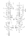
図1は、本実施形態の船舶の推進エンジンに高圧の燃料ガスを供給する燃料ガス供給システム10の構成の一例を示す図である。燃料ガス供給システム10は燃料ガスとしてエタンガスを用いるが、エタンガスに限定されず、メタンガスや天然ガス等を用いることができる。燃料ガスは、液体燃料が自然入熱によって気化したガスの他に、液体燃料を意図的に加熱して強制的に気化したガスも含まれる。
Hereinafter, the fuel gas supply system and the fuel gas supply method of the present invention will be described in detail.
FIG. 1 is a diagram illustrating an example of a configuration of a fuel
燃料ガス供給システム10は、船舶において、燃料ガスを加圧して推進エンジン14に供給するのに用いられる。本実施形態では、燃料ガスが燃料ガス源12から推進エンジン14に供給される方向を下流方向、その反対方向を上流方向といい、ある基準とする位置から下流方向の側を下流側といい、ある基準とする位置から上流方向の側を上流側という。
The fuel
本実施形態の燃料ガス供給システム10は、燃料ガスの供給を受けて船舶を推進させる推進エンジン14に、燃料ガスを供給するために、燃料ガスを加圧して燃料ガス源12の側から推進エンジン14の側に流す複数のガス圧縮機構13a〜13eを備える。複数のガス圧縮機構13a〜13eは直列に設けられている。
ガス圧縮機構13a〜13eは、ガスコンプレッサ16a〜16eと、吸引スナッバ18a〜18eと、吐出スナッバ20a〜20eと、熱交換器22a〜22eと、第1バイパス管24c,24dと、第2バイパス管24a,24b,24eと、制御バルブ26a〜26eと、制御装置28a〜28eと、を主に備える。この他に、燃料ガス供給システム10は、ガス圧縮機構13eの下流側に熱交換器22fを備える。
The fuel
The
燃料ガス源12は、エタンガスを燃料ガスとして貯蔵している。燃料ガス源12は、液化したエタンを貯蔵してもよく、ガスを貯蔵してもよい。燃料ガス源12が液化したエタンを貯蔵する場合、燃料ガス供給システム10には、液体のエタンをガスにするための図示されない熱交換器が設けられる。
本実施形態を適用する船舶はエタンを荷物として運搬する運搬船であってもよいし、上記運搬船以外の船舶に適用することもできる。
The
The ship to which the present embodiment is applied may be a transport ship that transports ethane as luggage, or can be applied to ships other than the transport ship.
推進エンジン14は供給される燃料ガスを燃焼室で燃焼させて動力を取り出し、主軸15aおよびプロペラ15bを回転させる。推進エンジン14には、例えば2ストロークサイクルの低速ディーゼルエンジンを用いることができる。
推進エンジン14は、ガバナ15cと接続されて、ガバナ15cにより推進エンジン14の駆動が制御されている。ガバナ15cは、主軸15aの回転を計測するように設けられた回転計15dにより計測された主軸回転数が目標回転数になるように、推進エンジン14に燃料ガスを供給する供給ラインに設けられた図示しない流量制御弁の開度を制御することで、推進エンジン14の駆動を制御する。すなわち、ガバナ15cは、推進エンジン14と推進用のプロペラ15bを接続した主軸15aの主軸回転数が目標回転数になるように、推進エンジン14の負荷を定め、これに基づいて燃料ガスの燃料供給量を制御する装置である。ガバナ15cは、気象、海象の風、波高等の自然状況の変化によって変化する主軸回転数が目標回転数に維持されるように、推進エンジン14の負荷を定める他、オペレータの減速、加速、旋回等の指示によって提供されるプロペラ回転数の操作指令値に応じて、推進エンジン14の負荷を定めることもできる。ガバナ15cは、定めた負荷に基づいて、最下流に位置するガスコンプレッサ16eの吐出側の目標圧力を設定する。
The
The
ガスコンプレッサ16a〜16eは、燃料ガスを推進エンジン14に供給するために、燃料ガスを圧縮して燃料ガス源12の側から推進エンジン14の側に流す直列に接続された多段のコンプレッサである。ガスコンプレッサ16a〜16eは、吸引スナッバ18a〜18e内の燃料ガスを吸引して加圧する部分である。ガスコンプレッサ16a〜16eは、例えば、ガスコンプレッサ16a〜16e内の可動部(プランジャ又はピストン)が直線往復運動をすることによって気体を吸い込み、その後圧縮する、往復圧縮機を用いることができる。ガスコンプレッサ16a〜16eのうち、ガスコンプレッサ16a〜16dは、無給油式圧縮機が用いられ、高圧に燃料ガスを加圧するガスコンプレッサ16eには給油式圧縮機が用いられる。ガスコンプレッサ16a〜16eの可動部は、図示されない駆動源(例えば電動モータ)の動力で回転するクランク軸を介して連動して駆動される。ガスコンプレッサ16a〜16eにおいて、燃料ガスはそれぞれ同程度の圧縮率で段階的に圧縮されることで、燃料ガスは圧縮率の5乗まで圧縮される。例えば、ガスコンプレッサ16a〜16eのそれぞれにおいて3〜4倍に圧縮することで、燃料ガスは35〜45倍に圧縮される。例えば、ガスコンプレッサ16aの吸引側における燃料ガスの圧力が0.1MPaであれば、ガスコンプレッサ16aの吐出側の圧力は約0.4MPa、ガスコンプレッサ16bの吐出側の圧力は約1.3MPa、ガスコンプレッサ16cの吐出側の圧力は約4MPa、ガスコンプレッサ16dの吐出側の圧力は約12〜13MPaとなる。そして、ガスコンプレッサ16eの吐出側の圧力は設定された目標圧力まで上昇される。
The gas compressors 16 a to 16 e are multi-stage compressors connected in series to compress the fuel gas and flow it from the
吸引スナッバ18a〜18eは、ガスコンプレッサ16a〜16eそれぞれに付随して設けられ、ガスコンプレッサ16a〜16eそれぞれの上流側に設けられる、圧縮前の燃料ガスを一時貯留する容器である。したがって、吸引スナッバ18a〜18e内の圧力は、ガスコンプレッサ16a〜16eそれぞれで加圧する直前の燃料ガスの圧力に相当する。
The
吐出スナッバ20a〜20eは、ガスコンプレッサ16a〜16eそれぞれに付随して設けられ、ガスコンプレッサ16a〜16eそれぞれの下流側に設けられる、圧縮後の燃料ガスを一時貯留する容器である。吐出スナッバ20a〜20eには、貯留する燃料ガスの圧力を計測する圧力計19a〜19eが設けられている。さらに、圧力計19fが、推進エンジン14に供給する圧力を計測するために、推進エンジン14の接続直前の供給ラインに設けられている。圧力計19a〜19fの計測結果は、後述する制御部28a〜28eに送られる。吐出スナッバ20a〜20eには、予め定めた圧力で弁が開放する図示されない安全弁が設けられている。
The
熱交換器22a〜22eは、ガスコンプレッサ16a〜16eそれぞれに付随するように、ガスコンプレッサ16a〜16eそれぞれで燃料ガスが圧縮されることにより高温になった燃料ガスの温度を、燃料ガスと冷媒との熱交換により温度を調整する装置である。熱交換器22a〜22eは、燃料ガスの推進エンジン14へ向かう流れ方向において吐出スナッバ20a〜20eより下流側に設けられている。熱交換器22a〜22eにおける冷媒は、特に制限されないが、燃料ガス源12から供給される低温の燃料ガスを用いることができる。熱交換器22a〜22dは、それぞれの下流側に位置する吸引スナッバ18b〜18eと供給ラインを介して接続される。
熱交換器22fは、ガス圧縮機構13a〜13eのうち最下流に位置するガス圧縮機構13eの熱交換器22eのさらに下流側に設けられ、ガス圧縮機構13eの熱交換器22eから流れる燃料ガスの温度を推進エンジン14が要求するガス温度に調整する最終熱交換器である。
熱交換器22eと熱交換器22fとの間には、逆止弁30が設けられている。逆止弁30は、推進エンジン14の負荷変動に伴って燃料ガスが熱交換器22e、さらには第2バイパス管24eを通って上流側に流れる(逆流する)ことを防止する。
As the
The heat exchanger 22f is provided further downstream of the
A
第1バイパス管24c,24dは、ガスコンプレッサ16c,16dのそれぞれに付随した熱交換器22c,22dの燃料ガスの出力端と、ガスコンプレッサ16c,16dそれぞれよりも燃料ガスの流れ方向の上流側に設けられたガスコンプレッサ16b,16cに付随した吐出スナッバ20b,20cとの間を、ガスコンプレッサ16c,16dを経由することなく繋いでいる。
第2バイパス管24a,24b,24eは、ガスコンプレッサ16a,16b,16eのそれぞれに付随した熱交換器22a,22b,22eの燃料ガスの出力端と、ガスコンプレッサ16a,16b,16eそれぞれに付随した吸引スナッバ18a,18b,18eとの間を、ガスコンプレッサ16a,16b,16eを経由することなく繋いでいる。
The
The
第1バイパス管24c,24d及び第2バイパス管24a,24b,24eには、燃料ガスが流れる量を制御する制御バルブ26a〜26eが設けられている。
制御バルブ26a〜26eそれぞれの開度は、対応するガスコンプレッサ16a〜16eに付随する吐出スナッバ20a〜20eの圧力が予め設定された圧力の目標値になるように、制御される。すなわち、第1バイパス管24c,24d及び第2バイパス管24a,24b,24eを流れる燃料ガスの流量は、対応する吐出スナッバ20a〜20e内の燃料ガスの圧力に基づいて制御される。この燃料ガスの流量の制御は、制御部28a〜eから送られる制御バルブ26a〜26eの開度の、吐出スナッバ20a〜20e内の燃料ガスの圧力に基づく制御信号によって行われる。
The
The opening degree of each of the
図2は、ガスコンプレッサ16bが下流方向に吐出する燃料ガスの流量と、第2バイパス管24bを上流方向に向かって逆流する燃料ガスの流量を説明する図である。図2では、2段目のガスコンプレッサ16bと第2バイパス管24bの流れを説明しているが、これ以外のガスコンプレッサ16a,16c,16d,16e、第2バイパス管24a,24e及び第1バイパス管24c,24dにおいても同様の挙動をするので、ガスコンプレッサ16b及び第2バイパス管24bを代表して説明する。図2に示されるように、例えば、上流側から1時間当たり1500kgの燃料ガスが供給され、ガスコンプレッサ16bが1時間当たり2000kgの燃料ガスを圧縮して下流側に吐出する時、第2バイパス管24bを介して1時間当たり500kgの燃料ガスを逆流させて吸引スナッバ18bに戻す。このように、吐出スナッバ20bから熱交換器22bを通過させて1時間当たり500kgの燃料ガスが逆流するように、制御バルブ26bの開度は制御されている。これにより、熱交換器22bの出力端から下流側に1時間当たり1500kgの燃料ガスを定常的に流すことができる。したがって、吐出スナッバ20bにおける燃料ガスの圧力は一定に保つことができる。
FIG. 2 is a diagram for explaining the flow rate of the fuel gas discharged from the
本実施形態では、上流側から第3番目及び第4番目のガス圧縮機構13c,13dには、第1バイパス管24c,24dが設けられている。第1バイパス管24c,24dは、熱交換器22c,22dの燃料ガスの出力端と、熱交換器22b,22cの上流側にある吐出スナッバ20b,20cとの間を繋ぐ。熱交換器22c,22dの出力端における燃料ガスの圧力は、吐出スナッバ20b,20cにおける圧力に比べて高いので、第1バイパス管24c,24d内を燃料ガスが上流方向に向かって流れる(逆流する)とき、燃料ガスは等エンタルピー変化を行って燃料ガスの温度は低下する。
ここで、推進エンジン14の負荷が変化してガスコンプレッサ16a〜16eの駆動が変化すると、吐出スナッバ20a〜20eにおける燃料ガスの圧力は変化し、その結果、吐出スナッバ20a〜20eにおける燃料ガスの圧力に応じて制御される制御バルブ26a〜26eの開度も変化する。このため、第1バイパス管24c,24d及び第2バイパス管24a,24b,24eを通過して低温となった燃料ガスの流量も変化する。第1バイパス管24c,24d及び第2バイパス管24a,24b,24eを通過して低温となった燃料ガスの流量が変化すると、その燃料ガスの供給先における温度も変化する。本実施形態は、第1バイパス管24c,24dを用いて、吸引スナッバ18c,18dではなく、吸引スナッバ18c,18d及び熱交換器22b,22cより上流側にある吐出スナッバ20b,20cに燃料ガスを供給し、熱交換器22b,22cを再度通過させるように構成されている。このため、ガスコンプレッサ16a〜16eの駆動が変化しても、燃料ガスの温度を目標温度から大きくずれることなく安定的に維持することができる。
In the present embodiment, the first and
Here, when the load of the
本実施形態において、第3番目及び第4番目のガス圧縮機構13c,13dに第1バイパス管24c,24dが設けられるのは、本実施形態で用いる燃料ガスがエタンガスであることに依拠している。具体的には、第3番目のガス圧縮機構13cの熱交換器22cの出力端及び第4番目のガス圧縮機構13dの吸引スナッバ18dにおける燃料ガスの状態(圧力及び温度)は、エタンの臨界点(臨界圧力=4.73MPa、臨界温度=32.3℃)に極めて近くなっている。一般に臨界点にガスが近づくほど、ガス温度に対するガス密度の変化は大きくなる。本実施形態では、上述したように、吐出スナッバ20c,20dの圧力に基づいて制御バルブ26c,26dの開度を制御して燃料ガスの流量を制御しているので、臨界点付近の燃料ガスの温度は目標温度に安定して維持させなければ、ガスの密度が変化することになり、この結果、燃料ガスの目標量を推進エンジン14に供給することはできない。この理由から、本実施形態では、第3番目及び第4番目のガス圧縮機構13c,13dに第1バイパス管24c,24dが設けられている。
本実施形態のガス圧縮機構13c,13dでは、制御バルブ26c,26d(第1制御バルブ)は、第1バイパス管24c,24dを流れる燃料ガスの単位時間当たりの流量を制御するので、ガスコンプレッサ16c,16dの駆動が変化しても、燃料ガスの圧力を目標圧力に制御しつつ、安定した温度の燃料ガスを吐出させることができる。これにより燃料ガスの目標量を、推進エンジン14に供給することができる。
In the present embodiment, the first and
In the
図3は、本実施形態の燃料ガス供給システム10に、燃料ガスとしてエタンガスを用いたときの一例のph線図である。エタンガスは、吸引スナッバ18aに供給される直前の状態1s(図1参照)を出発状態とする。
図3では、各状態の圧力及び温度は以下の通りである。
状態1s:圧力0.1MPa、温度−30℃、
状態1d:圧力0.4MPa、温度40℃、
状態2s:圧力0.4MPa、温度40℃、
状態2d:圧力1.3MPa、温度105℃、
状態3s:圧力1.3Mpa、温度45℃、
状態3d:圧力4.25MPa、温度110℃、
状態4s:圧力4.25MPa、温度45℃、
状態4d:圧力12.8MPa、温度120℃、
状態5s:圧力12.8MPa、温度90℃、
状態5d:圧力43.0MPa、温度140℃
状態X:圧力43.0MPa、温度90℃、
状態Y:圧力43.0MPa、温度45℃、
状態1f:圧力0.1MPa、温度35℃、
状態2f:圧力0.4MPa、温度35℃、
状態3f:圧力1.3MPa、温度5℃、
状態4f:圧力4.25MPa、温度30℃、
状態5f:圧力12.8MPa、温度80℃。
FIG. 3 is a ph diagram of an example when ethane gas is used as the fuel gas in the fuel
In FIG. 3, the pressure and temperature of each state are as follows.
State X: pressure 43.0 MPa, temperature 90 ° C.,
State Y: pressure 43.0 MPa, temperature 45 ° C.
ここで、熱交換器22aは、実質的に作動させないため、状態1dと状態2sは略同じである。
上述の各状態において、エタンガスの流れ方向の最下流に位置する第5番目のガス圧縮機構13e(最下流ガス圧縮機構)は、第2バイパス管24eを備える圧縮機構(第2圧縮機構)であり、第2バイパス管24eを通過したエタンガスの温度と、ガス圧縮機構13eに隣り合うガス圧縮機構13d(隣接ガス圧縮機構)の熱交換器23dの出力端から出るエタンガスの温度との間の温度差は、10℃(状態5sの温度90℃と状態5fの温度80℃の温度差)である。本実施形態では、上記温度差は15℃以内であることが好ましい。上記温度差は15℃以内であるので、制御バルブ26eの開度により第2バイパス管24eを流れるエタンガスの流量が大きく変化しても、吸引スナッバ18eにおけるエタンガスの温度は安定している。したがって、ガスコンプレッサ16eによる加圧後のエタンガスの温度も安定しているので、推進エンジン14に供給するエタンガスの温度は、熱交換器22e,22fの熱交換の機能を調整しなくても安定させることができる。また、エタンガスの温度は安定するので、飽和蒸気線Svと飽和液線Slとで囲まれた領域(液体とガスが混在する状態)に入らないようにすることが確実にでき、燃料ガスの一部が液化することを防止できる。
Here, since the
In each of the above states, the fifth
第1バイパス管を流れる燃料ガスの温度及び圧力は、燃料ガスが第1バイパス管を流れるにつれて徐々に低下する。このとき、本実施形態では、第1バイパス管の少なくとも1つにおける供給元側の端及び供給先側の端の少なくも一方の、燃料ガスの温度と、燃料ガスの臨界温度との温度差は20℃以下であり、第1バイパス管の供給元側の端及び供給先側の端の少なくも一方の、燃料ガスの圧力と、燃料ガスの臨界圧力との圧力差は1.0MPa以下であることが好ましい。本実施形態では、第1バイパス管24dを流れる燃料ガスの温度及び圧力は等エントロピー変化により低下し、第1バイパス管24dの供給先側の端の、燃料ガスの温度(状態4fの温度)と、エタンの臨界温度との温度差は2.3℃であり、第1バイパス管24dの供給先側の端の、燃料ガスの圧力と、エタンの臨界圧力との圧力差は0.48MPaである。このように臨界点に近い状態の燃料ガスを、第1バイパス管24dを流れた燃料ガスを熱交換器22cに再度通過させるので燃料ガスの温度を安定させて維持させることができる。このため、臨界点に燃料ガスが近づくほど、ガス温度に対するガス密度の変化は大きくなっても、燃料ガスの温度を安定的に維持することにより、ガス密度の変化を抑制することができる。さらに、吐出スナッバ20dにおける燃料ガスの圧力に基づいて制御バルブ26dの開度を制御して燃料ガスの流量の制御を行っても、燃料ガスの目標量を推進エンジン14の側に安定して供給することができる。第1バイパス管24c,24dのいずれか一方の管のうち、供給先側の端及び供給元側の端の一方における燃料ガスの温度及び圧力は、第1バイパス管24c,24d及び第2バイパス管24a,24b,24eの供給先側の端及び供給元側の端における燃料ガスの温度及び圧力の中で、燃料ガスの臨界温度及び臨界圧力に最も近いことが好ましい。
The temperature and pressure of the fuel gas flowing through the first bypass pipe gradually decrease as the fuel gas flows through the first bypass pipe. At this time, in the present embodiment, the temperature difference between the temperature of the fuel gas and the critical temperature of the fuel gas is at least one of the end on the supply source side and the end on the supply destination side in at least one of the first bypass pipes. The pressure difference between the pressure of the fuel gas and the critical pressure of the fuel gas is 1.0 MPa or less at 20 ° C. or less and at least one of the supply source side end and the supply destination side end of the first bypass pipe. It is preferable. In the present embodiment, the temperature and pressure of the fuel gas flowing through the
本実施形態では、図1に示すように、ガス圧縮機構13a〜13eのうち、燃料ガスの流れ方向の最下流に位置するガス圧縮機構13eよりも推進エンジン14の側に設けられ、ガス圧縮機構13eから流れる燃料ガスの温度を推進エンジン14が要求するガス温度に調整する熱交換器22fを備えることが好ましい。これにより、推進エンジン14に安定した温度の燃料ガスを供給することができる。
In the present embodiment, as shown in FIG. 1, among the
本実施形態では、図1に示すように、第1バイパス管24c,24dを備えるガス圧縮機構13c,13dは、第1バイパス管24c,24dを流れる燃料ガスの単位時間当たりの流量を制御する制御バルブ26c,26dを備えることが、燃料ガスの逆流する流量を制御する点で好ましい。この場合、第1バイパス管24c,24dを燃料ガスが逆流する単位時間当たりの流量を制御することができる。
さらに、図1に示すように、本実施形態では、ガス圧縮機構13a〜13eのうちの一部のガス圧縮機構13a,13b,13e(第2ガス圧縮機構)は、熱交換器22a,22b,22eのガス出力端と吸引スナッバ18a,18b,18eとを、ガスコンプレッサ16a,16b,16eを経由することなく繋ぐ第2バイパス管24a,24b,24eを備えることが好ましい。この場合、ガス圧縮機構13a,13b,13eの熱交換器22a,22b,22eのガス出力端から、吸引スナッバ18a,18b,18eに、ガスコンプレッサ16a,16b,16eを経由することなく燃料ガスを逆流させることができる。これにより、第2バイパス管24a,24b,24e内で燃料ガスを逆流させることができ、推進エンジン14の側へ流す燃料ガスの流量を制御することができる。
In the present embodiment, as shown in FIG. 1, the
Furthermore, as shown in FIG. 1, in this embodiment, some
図4は、本実施形態の燃料ガス供給システム10に、燃料ガスとしてメタンガスを用いたときの一例のph線図である。
メタンガスは、吸引スナッバ18aに供給される直前の状態1s(図1参照)を出発状態とする。
図4では、各状態の圧力及び温度は以下の通りである。
状態1s:圧力0.1MPa、温度−70℃、
状態1d:圧力0.4MPa、温度15℃、
状態2s:圧力0.4MPa、温度45℃、
状態2d:圧力1.2MPa、温度135℃、
状態3s:圧力1.2Mpa、温度45℃、
状態3d:圧力4MPa、温度135℃、
状態4s:圧力4MPa、温度45℃、
状態4d:圧力12.3MPa、温度135℃、
状態5s:圧力12.3MPa、温度45℃、
状態5d:圧力43MPa、温度145℃
状態X:圧力43MPa、温度70℃、
状態Y:圧力43MPa、温度45℃、
状態1f:圧力0.1MPa、温度44℃、
状態2f:圧力0.4MPa、温度42℃、
状態3f:圧力1.2MPa、温度32℃、
状態4f:圧力4MPa、温度18℃、
状態5f:圧力12.3MPa、温度40℃。
FIG. 4 is a ph diagram of an example when methane gas is used as the fuel gas in the fuel
The methane gas starts from the
In FIG. 4, the pressure and temperature of each state are as follows.
State X: pressure 43 MPa, temperature 70 ° C.
State Y: pressure 43 MPa, temperature 45 ° C.
ここで、熱交換器22aは、燃料ガスを加熱して燃料ガスの温度を上げている。
上述の各状態において、メタンガスの流れ方向の最下流に位置する第5番目のガス圧縮機構13e(最下流ガス圧縮機構)は、第2バイパス管24eを備える圧縮機構(第2圧縮機構)であり、第2バイパス管24eを通過したメタンガスの温度と、ガス圧縮機構13eに隣り合うガス圧縮機構13d(隣接ガス圧縮機構)の熱交換器23dから出るメタンガスの温度との間の温度差は、5℃(状態5sの温度45℃と状態5fの温度40℃の温度差)である。この場合においても、上記温度差は15℃以内であることが好ましい。上記温度差は15℃以内であるので、制御バルブ26eの開度により第2バイパス管24eを流れるメタンガスの流量が大きく変化しても、吸引スナッバ18eにおけるメタンガスの温度は安定している。したがって、ガスコンプレッサ16eによる加圧後のメタンガスの温度も安定しているので、推進エンジン14に供給するメタンガスの温度は、熱交換器22e,22fの熱交換の機能を調整しなくても安定させることができる。なお、メタンの臨界圧力は4.6MPaであり、臨界温度は−82.6℃であり、燃料ガスのいずれの状態の温度も臨界温度から離れているので、エタンガスの場合のように、臨界点を考慮して燃料ガスの温度を制御する必要はない。図4に示す例では、状態2s,3s,4s,5sでは、推進エンジン14の要求する燃料ガスのガス温度である、略45℃に定めている。
Here, the
In each of the above-described states, the fifth
このように、本実施形態では、使用する燃料ガスの種類に応じて、燃料ガス供給システム10における燃料ガスの各状態の温度は異なり、燃料ガスが、複数の燃料ガスの種類から選択される場合、選択された燃料ガスの種類に応じて、燃料ガスが第1バイパス管24c,24d及び第2バイパス管24a,24b,24eを逆流する単位時間当たりの流量を制御することが好ましい。
Thus, in the present embodiment, the temperature of each state of the fuel gas in the fuel
なお、図1に示す燃料ガス供給システム10の中で、最下流に位置するガス圧縮機構13eの代わりに、図5に示すガス圧縮機構13e’を用いることも好ましい。図5は、本実施形態における最下流のガス圧縮機構の構成の変形例を説明する図である。
ガス圧縮機構13e’は、ガス圧縮機構13eと同じ構成の吸引スナッバ18e、ガスコンプレッサ16e、吐出スナッバ20e、熱交換器22e、第2バイパス管24e、制御バルブ26eを備える他、第3バイパス管24f及び制御バルブ26fを備える。第3バイパス管24fは、吐出スナッバ20eと吸引スナッバ18eを繋ぐ。制御バルブ26fは、第3バイパス管24fを流れる燃料ガスの流量を制御することで、第2バイパス管24eから吸引スナッバ18eに流れ込む燃料ガスの量と第3バイパス管24fから吸引スナッバ18eに流れ込むる燃料ガスの量の比率を変えて、吸引スナッバ18eの燃料ガスの温度を目標温度に近づけ維持させるために用いられる。燃料ガスがエタンガスである場合、上記等エンタルピー変化によって低下した燃料ガスの温度は例えば90℃に近づくように、また、燃料ガスがメタンガスである場合、上記等エンタルピー変化によって低下した燃料ガスの温度は例えば45℃に近づくように、第3バイパス管24f内を吸引スナッバ18eに向かって逆流する燃料ガスの単位時間当たりの流量が制御部28eにより制御されることが好ましい。これにより、熱交換器22dから吸引スナッバ18eに流れ込む燃料ガスの温度(エタンガスの場合90℃、メタンガスの場合45℃)に近づけることができ、ガスコンプレッサ16eの駆動が変化した場合であっても、安定した温度の燃料ガスを推進エンジン14の側に供給することができる。
すなわち、ガス圧縮機構13e’は、第2バイパス管24eの他に、吐出スナッバ20eと吸引スナッバ18eとを、ガスコンプレッサ16eを経由することなく繋ぐ第3バイパス管24fを備え、第2バイパス管24eと第3バイパス管24fを流れる燃料ガスの単位時間当たりの流量をそれぞれ制御する制御部28eを備えることが好ましい。
In the fuel
The
In other words, in addition to the
以上、本発明の燃料ガス供給システム及び燃料ガス供給方法について詳細に説明したが、本発明は上記実施形態に限定されず、本発明の主旨を逸脱しない範囲において、種々の改良や変更をしてもよいのはもちろんである。 The fuel gas supply system and the fuel gas supply method according to the present invention have been described in detail above. Of course it is also good.
10 燃料ガス供給システム
12 LNGタンク
14 推進エンジン
15a 主軸
15b プロペラ
15c ガバナ
15d 回転計
16a〜16e ガスコンプレッサ
18a〜18e 吸引スナッバ
19a〜19f 圧力計
20a〜20e 吐出スナッバ
22a〜22f 熱交換器
24c,24d 第1バイパス管
24a,24b,24d 第2バイパス管
24f 第3バイパス管
26a〜26f 制御バルブ
28a〜28e 制御部
30 逆止弁
DESCRIPTION OF
Claims (15)
前記ガス圧縮機構のそれぞれは、
前記燃料ガスを前記推進エンジンに供給するために、前記燃料ガスを圧縮して前記燃料ガスの供給源の側から前記推進エンジンの側に流すガスコンプレッサと、
前記ガスコンプレッサに付随するように、前記ガスコンプレッサの吸引側及び吐出側に設けられた、圧縮前の前記燃料ガスを一時貯留する吸引スナッバ及び圧縮後の前記燃料ガスを一時貯留する吐出スナッバと、
前記ガスコンプレッサで圧縮された前記燃料ガスの温度を調整する、前記燃料ガスの前記推進エンジンへ向かう流れ方向において前記吐出スナッバより下流側に設けられた熱交換器と、を備え、
前記複数のガス圧縮機構のうちの第1ガス圧縮機構は、前記第1ガス圧縮機構の熱交換器のガス出力端と、前記第1ガス圧縮機構のガスコンプレッサよりも前記流れ方向の上流側に設けられた別のガス圧縮機構のガスコンプレッサの吐出スナッバとを、前記第1ガス圧縮機構のガスコンプレッサを経由することなく繋ぐ第1バイパス管を備える、
ことを特徴とする燃料ガス供給システム。 In order to supply the fuel gas to the propulsion engine that receives the supply of the fuel gas and propels the ship, the fuel gas is compressed and flows from the fuel gas supply source side to the propulsion engine side. Provided with a plurality of gas compression mechanisms,
Each of the gas compression mechanisms is
A gas compressor for compressing and flowing the fuel gas from the fuel gas supply source side to the propulsion engine side in order to supply the fuel gas to the propulsion engine;
A suction snubber that temporarily stores the fuel gas before compression, and a discharge snubber that temporarily stores the fuel gas after compression, provided on the suction side and discharge side of the gas compressor, so as to accompany the gas compressor;
A heat exchanger that adjusts the temperature of the fuel gas compressed by the gas compressor and that is provided downstream of the discharge snubber in the flow direction of the fuel gas toward the propulsion engine,
The first gas compression mechanism of the plurality of gas compression mechanisms is disposed upstream of the gas output end of the heat exchanger of the first gas compression mechanism and the gas compressor of the first gas compression mechanism in the flow direction. A first bypass pipe that connects a discharge snubber of a gas compressor of another gas compression mechanism provided without passing through the gas compressor of the first gas compression mechanism;
A fuel gas supply system.
前記最下流ガス圧縮機構における前記第2バイパス管を通過した前記燃料ガスの温度と、前記最下流ガス圧縮機構に隣り合う隣接ガス圧縮機構の熱交換器から出る前記燃料ガスの温度との間の温度差は、15℃以内である、請求項3に記載の燃料ガス供給システム。 The most downstream gas compression mechanism located at the most downstream in the flow direction of the fuel gas is the second compression mechanism,
Between the temperature of the fuel gas that has passed through the second bypass pipe in the most downstream gas compression mechanism and the temperature of the fuel gas that exits from the heat exchanger of the adjacent gas compression mechanism adjacent to the most downstream gas compression mechanism The fuel gas supply system according to claim 3, wherein the temperature difference is within 15 ° C.
前記第2バイパス管と前記第3バイパス管を流れる前記燃料ガスの単位時間当たりの流量を制御する制御部を備える、請求項3または4に記載の燃料ガス供給システム。 Among the gas compression mechanisms, the most downstream gas compression mechanism located on the most downstream side in the fuel gas flow direction includes, in addition to the second bypass pipe, a discharge snubber and a suction snubber in the most downstream gas compression mechanism. A third bypass pipe connected without going through the gas compressor in the most downstream gas compression mechanism,
5. The fuel gas supply system according to claim 3, further comprising a control unit configured to control a flow rate per unit time of the fuel gas flowing through the second bypass pipe and the third bypass pipe.
前記第1バイパス管の少なくとも1つにおける供給元側端及び供給先側端の少なくも一方の、前記燃料ガスの温度と、前記燃料ガスの臨界温度との温度差は20℃以下であり、前記第1バイパス管の供給元端及び供給先端の少なくも一方の、前記燃料ガスの圧力と、前記燃料ガスの臨界圧力との圧力差は1.0MPa以下である、請求項1〜5のいずれか1項に記載の燃料ガス供給システム。 The temperature and pressure of the fuel gas flowing through the first bypass pipe of the first gas compression mechanism decreases as it flows through the first bypass pipe,
The temperature difference between the temperature of the fuel gas and the critical temperature of the fuel gas at least one of the supply source side end and the supply destination side end in at least one of the first bypass pipes is 20 ° C. or less, The pressure difference between the pressure of the fuel gas and the critical pressure of the fuel gas at least one of the supply source end and the supply tip of the first bypass pipe is 1.0 MPa or less. 2. A fuel gas supply system according to item 1.
前記ガス圧縮機構のそれぞれは、
前記燃料ガスを前記推進エンジンに供給するために、前記燃料ガスを圧縮して前記燃料ガスの供給源の側から前記推進エンジンの側に流すガスコンプレッサと、
前記ガスコンプレッサに付随するように、前記ガスコンプレッサの吸引側及び吐出側に設けられた、圧縮前の前記燃料ガスを一時貯留する吸引スナッバ及び圧縮後の前記燃料ガスを一時貯留する吐出スナッバと、
前記ガスコンプレッサで圧縮された前記燃料ガスの温度を調整する、前記吐出スナッバよりも前記推進エンジンの側に設けられた熱交換器と、を備える、燃料ガス供給システムにおいて、
燃料ガスを、前記ガス圧縮機構で段階的に圧縮して推進エンジンに供給するステップと、
前記ガス圧縮機構のうちの第1ガス圧縮機構の熱交換器のガス出力端から、第1バイパス管を通して、前記第1ガス圧縮機構のガスコンプレッサよりも前記流れ方向の上流側に設けられた別のガス圧縮機構のガスコンプレッサの吐出スナッバに、前記第1ガス圧縮機構のガスコンプレッサを経由することなく前記燃料ガスが逆流するステップと、を備えることを特徴とする燃料ガス供給方法。 In order to supply the fuel gas to the propulsion engine that receives the supply of the fuel gas and propels the ship, the fuel gas is compressed and sent from the fuel gas supply side to the propulsion engine side in series. A plurality of gas compression mechanisms provided,
Each of the gas compression mechanisms is
A gas compressor for compressing and flowing the fuel gas from the fuel gas supply source side to the propulsion engine side in order to supply the fuel gas to the propulsion engine;
A suction snubber that temporarily stores the fuel gas before compression, and a discharge snubber that temporarily stores the fuel gas after compression, provided on the suction side and discharge side of the gas compressor, so as to accompany the gas compressor;
A fuel gas supply system comprising: a heat exchanger provided on a side of the propulsion engine with respect to the discharge snubber for adjusting a temperature of the fuel gas compressed by the gas compressor.
Supplying fuel gas to the propulsion engine after being compressed in stages by the gas compression mechanism;
The gas compression mechanism is provided separately from the gas output end of the heat exchanger of the first gas compression mechanism through the first bypass pipe and on the upstream side in the flow direction from the gas compressor of the first gas compression mechanism. And a step of causing the fuel gas to flow back to a discharge snubber of the gas compressor of the gas compression mechanism without passing through the gas compressor of the first gas compression mechanism.
前記最下流ガス圧縮機構における前記第2バイパス管を通過した前記燃料ガスの温度と、前記最下流ガス圧縮機構に隣り合う隣接ガス圧縮機構の熱交換器から出る前記燃料ガスの温度との間の温度差は15℃以内である、請求項10に記載の燃料ガス供給方法。 Of the plurality of gas compression mechanisms, the most downstream gas compression mechanism located on the most downstream side in the flow direction of the fuel gas is the second gas compression mechanism,
Between the temperature of the fuel gas that has passed through the second bypass pipe in the most downstream gas compression mechanism and the temperature of the fuel gas that exits from the heat exchanger of the adjacent gas compression mechanism adjacent to the most downstream gas compression mechanism The fuel gas supply method according to claim 10, wherein the temperature difference is within 15 ° C.
前記第2バイパス管と前記第3バイパス管を流れる前記燃料ガスの単位時間当たりの流量を制御する、請求項10に記載の燃料ガス供給方法。 Among the gas compression mechanisms, the most downstream gas compression mechanism located on the most downstream side in the fuel gas flow direction includes, in addition to the second bypass pipe, a discharge snubber and a suction snubber in the most downstream gas compression mechanism. A third bypass pipe connected without going through the gas compressor in the most downstream gas compression mechanism,
The fuel gas supply method according to claim 10, wherein a flow rate per unit time of the fuel gas flowing through the second bypass pipe and the third bypass pipe is controlled.
選択された燃料ガスの種類に応じて、前記燃料ガスが逆流する単位時間当たりの流量を制御する、請求項8〜14のいずれか1項に記載の燃料ガス供給方法。 The fuel gas is selected from a plurality of types of fuel gas,
The fuel gas supply method according to any one of claims 8 to 14, wherein a flow rate per unit time at which the fuel gas flows backward is controlled according to a type of the selected fuel gas.
Priority Applications (1)
| Application Number | Priority Date | Filing Date | Title |
|---|---|---|---|
| JP2016084905A JP6672544B2 (en) | 2016-04-21 | 2016-04-21 | Fuel gas supply system and fuel gas supply method |
Applications Claiming Priority (1)
| Application Number | Priority Date | Filing Date | Title |
|---|---|---|---|
| JP2016084905A JP6672544B2 (en) | 2016-04-21 | 2016-04-21 | Fuel gas supply system and fuel gas supply method |
Publications (2)
| Publication Number | Publication Date |
|---|---|
| JP2017194013A true JP2017194013A (en) | 2017-10-26 |
| JP6672544B2 JP6672544B2 (en) | 2020-03-25 |
Family
ID=60155871
Family Applications (1)
| Application Number | Title | Priority Date | Filing Date |
|---|---|---|---|
| JP2016084905A Active JP6672544B2 (en) | 2016-04-21 | 2016-04-21 | Fuel gas supply system and fuel gas supply method |
Country Status (1)
| Country | Link |
|---|---|
| JP (1) | JP6672544B2 (en) |
Citations (2)
| Publication number | Priority date | Publication date | Assignee | Title |
|---|---|---|---|---|
| JP2011517749A (en) * | 2008-03-10 | 2011-06-16 | ブルクハルト コンプレッション アーゲー | Natural gas fuel supply apparatus and method |
| JP2016505784A (en) * | 2012-12-20 | 2016-02-25 | クライオスター・ソシエテ・パール・アクシオンス・サンプリフィエ | Method and apparatus for reliquefying natural gas |
-
2016
- 2016-04-21 JP JP2016084905A patent/JP6672544B2/en active Active
Patent Citations (2)
| Publication number | Priority date | Publication date | Assignee | Title |
|---|---|---|---|---|
| JP2011517749A (en) * | 2008-03-10 | 2011-06-16 | ブルクハルト コンプレッション アーゲー | Natural gas fuel supply apparatus and method |
| JP2016505784A (en) * | 2012-12-20 | 2016-02-25 | クライオスター・ソシエテ・パール・アクシオンス・サンプリフィエ | Method and apparatus for reliquefying natural gas |
Also Published As
| Publication number | Publication date |
|---|---|
| JP6672544B2 (en) | 2020-03-25 |
Similar Documents
| Publication | Publication Date | Title |
|---|---|---|
| JP6700324B2 (en) | Natural gas fuel supply device and method | |
| KR101913008B1 (en) | Vessel having Gas Treatment System | |
| KR101758993B1 (en) | Treatment system of liquefied natural gas | |
| KR101884823B1 (en) | System for supplying fuel gas in ships | |
| JP4677375B2 (en) | How to use gas | |
| JP6665383B2 (en) | Fuel gas supply system and fuel gas supply method | |
| JP2016203852A (en) | Boil-off gas utilization system | |
| JP6651689B2 (en) | Fuel gas supply system, ship, and fuel gas supply method | |
| JP6521444B2 (en) | Fuel gas supply system for ships | |
| KR20170079873A (en) | Operation Method of Engine for a Ship | |
| JP6551684B2 (en) | Fuel gas supply system and fuel gas supply method | |
| JP2016200068A (en) | Fuel gas supply system for liquefied gas carrier | |
| KR20190030324A (en) | Gas Treatment System and Vessel having the same | |
| JP2017194013A (en) | Fuel gas supply system and fuel gas supply method | |
| JP6720440B2 (en) | Fuel gas supply system, ship, and fuel gas supply method | |
| JP6634633B2 (en) | Fuel gas supply system and fuel gas supply method | |
| JP6648374B2 (en) | Fuel gas supply system, ship, and fuel gas supply method | |
| JP6668566B2 (en) | Fuel gas supply system, ship, and fuel gas supply method | |
| KR102332936B1 (en) | Fuel Supply System and Ship having the same | |
| JP6740535B2 (en) | Fuel gas supply system, ship, and fuel gas supply method | |
| KR20190030329A (en) | Gas Treatment System and Vessel having the same | |
| JP2018066272A (en) | Fuel gas supply system, vessel, and fuel gas supply method |
Legal Events
| Date | Code | Title | Description |
|---|---|---|---|
| A711 | Notification of change in applicant |
Free format text: JAPANESE INTERMEDIATE CODE: A712 Effective date: 20180813 |
|
| A625 | Written request for application examination (by other person) |
Free format text: JAPANESE INTERMEDIATE CODE: A625 Effective date: 20190313 |
|
| A977 | Report on retrieval |
Free format text: JAPANESE INTERMEDIATE CODE: A971007 Effective date: 20191127 |
|
| A131 | Notification of reasons for refusal |
Free format text: JAPANESE INTERMEDIATE CODE: A131 Effective date: 20191217 |
|
| A521 | Request for written amendment filed |
Free format text: JAPANESE INTERMEDIATE CODE: A523 Effective date: 20200121 |
|
| TRDD | Decision of grant or rejection written | ||
| A01 | Written decision to grant a patent or to grant a registration (utility model) |
Free format text: JAPANESE INTERMEDIATE CODE: A01 Effective date: 20200204 |
|
| A61 | First payment of annual fees (during grant procedure) |
Free format text: JAPANESE INTERMEDIATE CODE: A61 Effective date: 20200205 |
|
| R150 | Certificate of patent or registration of utility model |
Ref document number: 6672544 Country of ref document: JP Free format text: JAPANESE INTERMEDIATE CODE: R150 |
|
| S111 | Request for change of ownership or part of ownership |
Free format text: JAPANESE INTERMEDIATE CODE: R313111 |
|
| R350 | Written notification of registration of transfer |
Free format text: JAPANESE INTERMEDIATE CODE: R350 |
|
| R250 | Receipt of annual fees |
Free format text: JAPANESE INTERMEDIATE CODE: R250 |
|
| R250 | Receipt of annual fees |
Free format text: JAPANESE INTERMEDIATE CODE: R250 |