JP2017193900A - Door lock device - Google Patents
Door lock device Download PDFInfo
- Publication number
- JP2017193900A JP2017193900A JP2016085699A JP2016085699A JP2017193900A JP 2017193900 A JP2017193900 A JP 2017193900A JP 2016085699 A JP2016085699 A JP 2016085699A JP 2016085699 A JP2016085699 A JP 2016085699A JP 2017193900 A JP2017193900 A JP 2017193900A
- Authority
- JP
- Japan
- Prior art keywords
- lock
- motor
- energization
- striker
- door
- Prior art date
- Legal status (The legal status is an assumption and is not a legal conclusion. Google has not performed a legal analysis and makes no representation as to the accuracy of the status listed.)
- Granted
Links
Images


Landscapes
- Lock And Its Accessories (AREA)
Abstract
Description
本発明は、車両のバックドアなどに使用されるドアロック装置に関する。 The present invention relates to a door lock device used for a back door of a vehicle.
従来、車両後部のバックドアをロックするドアロック装置として、特許文献1に記載のものがあり、例えば図3に示すように構成されている。すなわち、図3に示すように、車両のドア側にロック機構51のベース52が固定され、車両のボデー側にロック機構51によって把持または開放されるストライカ53が固定され、ベース52に形成されたストライカ進入溝54の両側に、フック部材57およびロック機構51のロック部材58が配設され、フック部材57の左端部およびロック部材58の下端部がそれぞれ支軸55,56により回転自在に枢支されている。
2. Description of the Related Art Conventionally, as a door lock device for locking a back door at the rear of a vehicle, there is one described in
フック部材57の右下端部および右上端部にそれぞれ、ストライカ保持溝57aおよびロック係合突部57bが形成され、ロック部材58には、ロック係合突部57bと係脱する係合段部58aが形成され、係合段部58aとロック係合突部57bとの係合により、図3に示すようにストライカ保持溝57aにストライカ53が保持されてドアがロック状態になる。
A striker holding groove 57a and a lock engagement protrusion 57b are formed on the lower right end and upper right end of the
フック部材57の上端部とロック部材58の中央部との間には引張ばね60が張設され、ロック係合突部57bが係合段部58aに係合する方向に付勢され、ロック係合突部57bの係合段部58aとの係合が外れると、引張ばね60の付勢力により、フック部材57がストライカ保持溝57aからストライカ53を開放する方向に回転するようになっている。
A
また、ロック部材58の上端には、電動ロック解除機構70に連動するローラ61が取り付けられ、このローラ61が周面を摺動するカム一体型ウォームホイール71が支軸72によりベース52に回転可能に取り付けられ、支軸72に巻回されたトーションばね73により、ウォームホイール71が図3に示す初期状態に復帰するように付勢されている。さらに、ウォームホイール71には、支軸72からの距離を徐々に大きくする形状のカム71aが設けられるとともに、その周縁にウォームギヤ歯面71dが形成されており、トーションばね73に抗してウォームホイール71が図3に示す位置から反時計方向に回転されると、カム71aによりローラ61が押されて、ロック部材58のロック部58aとロック係止部57bとの係合が解除される。さらに、図3に示すように、ベース52の上端部には、モータ74が収容されたモータハウジング75が固定され、ウォームギヤ76がカム一体ウォームホイール71の歯面71dに噛合するようにモータ74の出力軸74aに取り付けられている。
A roller 61 that is linked to the electric lock release mechanism 70 is attached to the upper end of the lock member 58, and a cam-integrated worm wheel 71 on which the roller 61 slides on the peripheral surface can be rotated to the base 52 by a support shaft 72. The worm wheel 71 is urged so as to return to the initial state shown in FIG. 3 by a
そして、図3に示すドアロック状態において、ドアに設けられた図示省略のロック解除ボタンがオン操作されることによりモータ74が駆動され、ウォームギヤ76が回転してカム一体ウォームホイール71が図3の反時計方向に回転され、カム71aがロック部材58のローラ61と接触してローラ61が押され、ロック部材58がフック部材57から離れる方向に回転されることにより、係合段部58aとロック係合突部57bとの係合が解除されると、引張ばね60の付勢力によりフック部材57が図3中の時計方向に回転し、ストライカ保持溝57aに保持されていたストライカ53が解放されてドアロックが解除される。
In the door lock state shown in FIG. 3, when a lock release button (not shown) provided on the door is turned on, the
一方、ドアロックが解除されてモータ74への通電が終了すると、トーションばね73の付勢力によりカム一体ウォームホイール71が初期位置に復帰されるとともに、ロック部材58がロック位置に戻され、モータ74の出力軸74aも通電時とは逆方向に回転される。この状態で開放されていたドアが閉められると、ストライカ進入溝54から進入したストライカ53が、フック57のストライカ保持溝57aに進入し、ストライカ53に押されたフック部材57が支軸55を中心に回動し、ロック係合突部57bの背面によりロック部材58が押されて一旦ロック解除位置に回転され、さらにストライカ53が進入することにより、係合段部58aにロック係止部57bが係合してロック状態に戻る。
On the other hand, when the door lock is released and energization of the
ところで、図3に示す従来構成のドアロック装置では、上記したように、ドアロックが解除されてモータ74への通電が終了すると、トーションばね73の付勢力によりカム一体ウォームホイール71が初期位置に復帰されてロック部材58がロック位置に戻されるため、ロックの際に大きな衝突音が発生する。この衝突音を低減するために、上記したようにモータ74の出力軸74aが通電時と逆方向に回転するのに伴ってモータ74に生じる起電力を利用して、トーションばね73の付勢力と逆の反力を発生させて、ロック部材58をゆっくりと元のロック位置に戻すようにすることが考えられている。
In the conventional door lock device shown in FIG. 3, as described above, when the door lock is released and energization of the
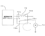
具体的には、図4に示すように、モータ74への通電を制御するボデーECUなどの通電制御手段77の出力端子と接地との間に、モータ74に並列にダイオード78を設け、図4中の矢印に示すようにモータ74に生じる起電力による電流を、モータ74、接地、ダイオード78の閉回路に流して上記した反力を発生する手法や、図5に示すように、リレー79のリレーコイル79dをボデーECUなどの制御部77に接続して制御部77よりリレーコイル79dを通電制御し、バッテリBおよびモータ74をリレー79の常開接点79aおよび共通端子79cにそれぞれ接続するとともに、リレー79の常閉接点79bを接地し、リレー79のリレーコイル79dの励磁を止めてモータ74の通電を終了することによって図5中の矢印に示すようにモータ74に生じる起電力による電流を、モータ74、接地、リレー79の常閉接点79b、共通端子79cの閉回路に流して上記した反力を発生する手法がある。
Specifically, as shown in FIG. 4, a
しかし、図4、図5の手法では、ダイオード78や、常閉接点79bを有するリレー79が必要になり、部品点数が多くなってコストの上昇を招き、リレー79の場合には常閉接点79bがあることによってリレー79自体が大型になり、装置全体が大型化するという問題がある。
However, the methods of FIGS. 4 and 5 require the
本発明は、ドアロック時に付勢手段の付勢によりロック方向に回転するロック部材に対して、簡単かつ安価な構成により、モータに生じる起電力を利用した反力を発生させることができるようにすることを目的とする。 According to the present invention, a reaction force using an electromotive force generated in a motor can be generated with a simple and inexpensive configuration with respect to a lock member that rotates in a lock direction by the urging force of the urging means when the door is locked. The purpose is to do.
上記した目的を達成するために、本発明のドアロック装置は、車両のドアとボデーのいずれか一方に固定したストライカと、前記ドアと前記ボデーの他方に回転自在に設けられ前記ストライカに係脱するフック部材と、前記ドアと前記ボデーの他方に回転自在に設けられ、付勢手段の付勢力により前記フック部材を前記ストライカに係合状態に保持し前記フック部材の回転を規制してロックし、前記付勢手段に抗した回転により前記フック部材を前記ストライカとの係合状態から解放するロック部材と、通電により前記ロック部材を前記付勢手段に抗してロック解除方向に回転させ前記フック部材を前記係合状態から解放し、通電停止により前記ロック部材を前記付勢手段の付勢力によりロック方向への回転を許容するモータと、前記モータの回転を前記ロック部材の回転に変換して前記ロック部材に伝達する伝達手段とを備えるドアロック装置において、前記モータへの通電および通電停止を制御する通電制御手段を備え、前記通電制御手段は、通電停止後において、前記付勢手段の付勢力による前記ロック部材のロック方向への回転が前記伝達手段を介して前記モータに通電時と逆方向への回転として伝達される際に、前記モータに少なくとも1回のパルス状の通電を行うことを特徴としている。 In order to achieve the above-described object, a door lock device according to the present invention includes a striker fixed to one of a vehicle door and a body, and rotatably provided on the other of the door and the body. A hook member that rotates, and is rotatably provided on the other of the door and the body, and the hook member is held in engagement with the striker by the urging force of the urging means to restrict and lock the rotation of the hook member. A lock member that releases the hook member from an engaged state with the striker by rotation against the biasing means, and the hook member that rotates in the unlocking direction against the biasing means by energization. A motor that releases the member from the engaged state and allows the lock member to rotate in the lock direction by the urging force of the urging means when the energization is stopped; and the motor In a door lock device comprising a transmission means for converting rotation to rotation of the lock member and transmitting the rotation to the lock member, the door lock device comprises energization control means for controlling energization and deenergization to the motor, the energization control means, After the energization is stopped, when the rotation of the locking member in the locking direction by the urging force of the urging means is transmitted to the motor as the rotation in the direction opposite to the direction of energization through the transmission means, It is characterized in that at least one pulsed energization is performed.
本発明によれば、モータへの通電停止後において、付勢手段の付勢力によるロック部材のロック方向への回転が伝達手段を介してモータに通電時と逆方向への回転として伝達される際に、通電制御手段により、モータに少なくとも1回のパルス状の通電が行われるため、従来のように閉回路を構成するためのダイオードやリレーの常閉接点が不要になり、簡単かつ安価な構成により、付勢手段の付勢によりロック方向に回転するロック部材に対して、モータに生じる起電力を利用した反力を発生させることができ、ロック時の衝突音を低減することが可能になる。 According to the present invention, after the energization of the motor is stopped, the rotation of the lock member in the locking direction by the urging force of the urging means is transmitted to the motor as the rotation in the opposite direction to the energization through the transmission means. In addition, the energization control means energizes the motor at least once in the form of a pulse, so there is no need for a normally closed contact of a diode or a relay for forming a closed circuit as in the prior art, and a simple and inexpensive configuration. Accordingly, a reaction force using an electromotive force generated in the motor can be generated on the lock member that rotates in the lock direction by the urging force of the urging means, and it becomes possible to reduce a collision sound at the time of locking. .
本発明に係るドアロック装置をバックドアに適用した一実施形態について、図1、図2を参照して詳細に説明する。なお、本実施形態におけるドアロック装置の基本的な構成は図3と同じであるため、以下では図3も参照して説明する。 An embodiment in which a door lock device according to the present invention is applied to a back door will be described in detail with reference to FIGS. 1 and 2. In addition, since the basic structure of the door lock apparatus in this embodiment is the same as FIG. 3, it demonstrates below also with reference to FIG.
本実施形態におけるドアロック装置は、図3と同様に構成され、車両のボデーに固定されたストライカ53と、ドアに回転自在に設けられストライカ53に係脱するフック部材57と、ドアに回転自在に設けられ、付勢手段であるトーションばね73の付勢力によりフック部材57をストライカ53に係合状態に保持しフック部材57の回転を規制してロックし、トーションばね73に抗した回転によりフック部材57をストライカ53との係合状態から解放するロック部材58と、通電によりロック部材58をトーションばね73に抗してロック解除方向に回転させ、フック部材57を係合状態から解放し、通電停止によりロック部材58をトーションばね73の付勢力によりロック方向への回転を許容するモータ74とを備えている。なお、図3のローラ61、カム一体ウォームホイール71、ウォームギヤ76により、モータ74の回転をロック部材58の回転に変換してロック部材58に伝達する本発明の「伝達手段」が構成されているが、伝達手段はこの構成に限るものではない。
The door lock device according to the present embodiment is configured in the same manner as in FIG. 3, and includes a striker 53 fixed to the vehicle body, a
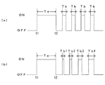
そして、本実施形態では、図1に示すように、モータ74への通電を制御するボデーECUなどの通電制御手段1の機能として、図2(a)に示すように、時刻t1に通電開始してロック解除動作を開始し、Ta時間後の時刻t2に通電停止してロック解除動作を終了したのち、モータ74にTb時間(Tb<Ta)のパルス状の通電を1回以上(図2(a)では、4回)定期的繰り返すようになっている。なお、通電時間Tbの長さについては適宜変更することができる。例えば、図2(b)に示すように、4回の通電のうち第1回目の通電時間(Tb1)が最も短く、第2回目以降(Tb2〜Tb4)徐々に通電時間が長くなるように構成してもよい。このようにすると、ロック時の衝突音が発生するタイミングに近づくに連れて反力を強くできるため、ロック時の衝突音の低減効果をさらに向上することができる。また、各通電のタイミングは周期的でなくてもよく、例えば、第1回目の通電と第2回目の通電の間隔と、第2回目の通電と第3回目の通電の間隔とが異なるようにしもよい。
In this embodiment, as shown in FIG. 1, as a function of the energization control means 1 such as a body ECU that controls energization of the
この通電制御手段1によるモータへの通電停止後において、トーションばね73の付勢力によるロック部材57のロック方向への回転が、ローラ61、カム一体ウォームホイール71、ウォームギヤ76による伝達手段を介してモータ74に通電時と逆方向への回転として伝達される際に、通電制御手段1により、モータ74に例えば4回のパルス状の通電が行われるため、従来のように閉回路を構成するためのダイオード(図4参照)やリレーの常閉接点(図5参照)が不要になり、トーションばね73の付勢によりロック方向に回転するロック部材57に対して、モータ74に生じる起電力を利用した反力が発生され、ロック部材57がゆっくりと元の位置に戻る。
After the energization of the motor is stopped by the energization control means 1, the rotation of the
したがって、上記した実施形態によれば、モータ74への通電停止後、通電制御手段1により、モータ74に少なくとも複数回(図2では4回)のパルス状の通電を行うことにより、従来のようなダイオードやリレーの常閉接点が不要な簡単かつ安価な構成により、トーションばね73の付勢によりロック方向に回転するロック部材57に対して、モータ74に生じる起電力を利用した反力を発生させて制動をかけることが可能になり、ロック時の衝突音を低減することができる。
Therefore, according to the above-described embodiment, after the energization of the
なお、本発明は上記した実施形態に限定されるものではなく、その趣旨を逸脱しない限りにおいて上述したもの以外に種々の変更を行なうことが可能である。 The present invention is not limited to the above-described embodiment, and various modifications other than those described above can be made without departing from the spirit of the present invention.
例えば、図5に示すリレー79とほぼ同様の構成であって常閉接点79bのないリレーを採用し、通電制御手段1により図2と同様の通電制御を行ってもよい。
For example, a relay having substantially the same configuration as the
また、上記した実施形態では、モータ74への通電停止後、通電制御手段1により、モータ74に少なくとも複数回(図2では4回)のパルス状の通電を行う場合について説明したが、少なくとも1回パルス状に通電すればよい。
In the above-described embodiment, the case where the
また、本発明に係るドアロック装置は、図3に示す構成に限定されるものではなく、モータの駆動により付勢手段に抗してロックを解除し、モータの駆動停止により付勢手段により元のロック状態に戻り、ロック状態に戻る際にモータがロック解除時と逆方向に回転して起電力を発生する構成であればよい。 Further, the door lock device according to the present invention is not limited to the configuration shown in FIG. 3, and the lock is released against the urging means by driving the motor, and the urging means is released by stopping the driving of the motor. Any configuration may be used as long as the motor rotates in the opposite direction to the unlocked state to generate an electromotive force when returning to the locked state.
また、上記した実施形態では、本発明を車両のバックドアに適用して例について説明したが、バックドア以外のドアにも本発明を適用できるのはいうまでもない。 In the above-described embodiment, the present invention is applied to a back door of a vehicle, and an example has been described. However, it goes without saying that the present invention can be applied to doors other than the back door.
1 …通電制御手段
53 …ストライカ
57 …フック部材
58 …ロック部材
61 …ローラ(伝達手段)
71 …カム一体ウォームホイール(伝達手段)
73 …トーションばね
74 …モータ
76 …ウォームギヤ(伝達手段)
DESCRIPTION OF
71 ... Cam integrated worm wheel (transmission means)
73 ...
Claims (1)
前記モータへの通電および通電停止を制御する通電制御手段を備え、
前記通電制御手段は、通電停止後において、前記付勢手段の付勢力による前記ロック部材のロック方向への回転が前記伝達手段を介して前記モータに通電時と逆方向への回転として伝達される際に、前記モータに少なくとも1回のパルス状の通電を行う
ことを特徴とするドアロック装置。 A striker fixed to one of a vehicle door and a body; a hook member rotatably provided on the other of the door and the body; and a hook member engaged with and disengaged from the striker; The hook member is held in engagement with the striker by the urging force of the urging means, the rotation of the hook member is restricted and locked, and the hook member is attached to the striker by the rotation against the urging means. A lock member that is released from the engaged state; and the energized member rotates the lock member in the unlocking direction against the urging means to release the hook member from the engaged state; A motor that allows rotation in the locking direction by the biasing force of the biasing means; In the door lock device and a transmission means for,
Comprising energization control means for controlling energization and deenergization of the motor;
In the energization control unit, after energization is stopped, the rotation of the lock member in the locking direction by the urging force of the urging unit is transmitted to the motor through the transmission unit as a rotation in the opposite direction to that during energization. In this case, the motor is energized at least once in the form of a pulse.
Priority Applications (1)
| Application Number | Priority Date | Filing Date | Title |
|---|---|---|---|
| JP2016085699A JP6689529B2 (en) | 2016-04-22 | 2016-04-22 | Door lock device |
Applications Claiming Priority (1)
| Application Number | Priority Date | Filing Date | Title |
|---|---|---|---|
| JP2016085699A JP6689529B2 (en) | 2016-04-22 | 2016-04-22 | Door lock device |
Publications (2)
| Publication Number | Publication Date |
|---|---|
| JP2017193900A true JP2017193900A (en) | 2017-10-26 |
| JP6689529B2 JP6689529B2 (en) | 2020-04-28 |
Family
ID=60156424
Family Applications (1)
| Application Number | Title | Priority Date | Filing Date |
|---|---|---|---|
| JP2016085699A Active JP6689529B2 (en) | 2016-04-22 | 2016-04-22 | Door lock device |
Country Status (1)
| Country | Link |
|---|---|
| JP (1) | JP6689529B2 (en) |
Cited By (1)
| Publication number | Priority date | Publication date | Assignee | Title |
|---|---|---|---|---|
| CN114517613A (en) * | 2022-01-24 | 2022-05-20 | 中国第一汽车股份有限公司 | Closing method and control device of electric suction door and vehicle |
Citations (4)
| Publication number | Priority date | Publication date | Assignee | Title |
|---|---|---|---|---|
| JPH0719544U (en) * | 1993-09-17 | 1995-04-07 | シロキ工業株式会社 | Door lock device |
| US5613716A (en) * | 1996-01-25 | 1997-03-25 | General Motors Corporation | Electronic vehicle door unlatch control |
| JP2000027510A (en) * | 1998-06-25 | 2000-01-25 | Mannesmann Vdo Ag | Locking device for movable member |
| DE102013111894A1 (en) * | 2013-10-29 | 2015-04-30 | Huf Hülsbeck & Fürst Gmbh & Co. Kg | An actuator assembly and method of operating such an actuator assembly |
-
2016
- 2016-04-22 JP JP2016085699A patent/JP6689529B2/en active Active
Patent Citations (4)
| Publication number | Priority date | Publication date | Assignee | Title |
|---|---|---|---|---|
| JPH0719544U (en) * | 1993-09-17 | 1995-04-07 | シロキ工業株式会社 | Door lock device |
| US5613716A (en) * | 1996-01-25 | 1997-03-25 | General Motors Corporation | Electronic vehicle door unlatch control |
| JP2000027510A (en) * | 1998-06-25 | 2000-01-25 | Mannesmann Vdo Ag | Locking device for movable member |
| DE102013111894A1 (en) * | 2013-10-29 | 2015-04-30 | Huf Hülsbeck & Fürst Gmbh & Co. Kg | An actuator assembly and method of operating such an actuator assembly |
Cited By (2)
| Publication number | Priority date | Publication date | Assignee | Title |
|---|---|---|---|---|
| CN114517613A (en) * | 2022-01-24 | 2022-05-20 | 中国第一汽车股份有限公司 | Closing method and control device of electric suction door and vehicle |
| CN114517613B (en) * | 2022-01-24 | 2023-02-24 | 中国第一汽车股份有限公司 | Closing method and control device of electric suction door and vehicle |
Also Published As
| Publication number | Publication date |
|---|---|
| JP6689529B2 (en) | 2020-04-28 |
Similar Documents
| Publication | Publication Date | Title |
|---|---|---|
| JP4874400B2 (en) | Unlocking actuator | |
| JP5576453B2 (en) | Seat belt device | |
| CN101165300B (en) | Locking device | |
| JP2011527258A (en) | Method for operating a motorcycle control system | |
| JP2017193900A (en) | Door lock device | |
| JP2012162264A (en) | Seat belt device | |
| JP5135604B2 (en) | Seat belt retractor | |
| JP2003240424A (en) | Operation auxiliary device | |
| JP2011098048A (en) | Toilet seat device | |
| CN114135171B (en) | A two-way motion automobile door lock mechanism | |
| JP6815896B2 (en) | Seat rotation device | |
| JP6482306B2 (en) | Automatic door opening and closing device for vehicles | |
| JP6216630B2 (en) | Focal plane shutter and camera | |
| JP2009275407A (en) | Door lock device | |
| KR100891503B1 (en) | Electric actuator for door lock with one-way clutch structure | |
| JP2016222109A (en) | Webbing winding device | |
| JP4913159B2 (en) | Seat belt device | |
| JP6260028B2 (en) | Vehicle door latch device | |
| JPH09151653A (en) | Silencer for latch bolt in lock | |
| JPH0914110A (en) | Starter | |
| JP2843046B2 (en) | Door lock device | |
| JP5263626B2 (en) | Seat belt retractor | |
| JP4343548B2 (en) | Door lock device | |
| JPH09317274A (en) | Actuator | |
| JP2890842B2 (en) | Door lock drive |
Legal Events
| Date | Code | Title | Description |
|---|---|---|---|
| A621 | Written request for application examination |
Free format text: JAPANESE INTERMEDIATE CODE: A621 Effective date: 20190225 |
|
| A977 | Report on retrieval |
Free format text: JAPANESE INTERMEDIATE CODE: A971007 Effective date: 20200129 |
|
| A131 | Notification of reasons for refusal |
Free format text: JAPANESE INTERMEDIATE CODE: A131 Effective date: 20200204 |
|
| A521 | Request for written amendment filed |
Free format text: JAPANESE INTERMEDIATE CODE: A523 Effective date: 20200225 |
|
| TRDD | Decision of grant or rejection written | ||
| A01 | Written decision to grant a patent or to grant a registration (utility model) |
Free format text: JAPANESE INTERMEDIATE CODE: A01 Effective date: 20200407 |
|
| A61 | First payment of annual fees (during grant procedure) |
Free format text: JAPANESE INTERMEDIATE CODE: A61 Effective date: 20200407 |
|
| R150 | Certificate of patent or registration of utility model |
Ref document number: 6689529 Country of ref document: JP Free format text: JAPANESE INTERMEDIATE CODE: R150 |
|
| R250 | Receipt of annual fees |
Free format text: JAPANESE INTERMEDIATE CODE: R250 |
|
| R250 | Receipt of annual fees |
Free format text: JAPANESE INTERMEDIATE CODE: R250 |
|
| R250 | Receipt of annual fees |
Free format text: JAPANESE INTERMEDIATE CODE: R250 |