JP2017193857A - Attachment structure of transverse member and guard fence - Google Patents
Attachment structure of transverse member and guard fence Download PDFInfo
- Publication number
- JP2017193857A JP2017193857A JP2016084142A JP2016084142A JP2017193857A JP 2017193857 A JP2017193857 A JP 2017193857A JP 2016084142 A JP2016084142 A JP 2016084142A JP 2016084142 A JP2016084142 A JP 2016084142A JP 2017193857 A JP2017193857 A JP 2017193857A
- Authority
- JP
- Japan
- Prior art keywords
- support
- column
- horizontal member
- angle
- vertical groove
- Prior art date
- Legal status (The legal status is an assumption and is not a legal conclusion. Google has not performed a legal analysis and makes no representation as to the accuracy of the status listed.)
- Pending
Links
- 238000003780 insertion Methods 0.000 claims abstract description 16
- 230000037431 insertion Effects 0.000 claims abstract description 16
- 230000001681 protective effect Effects 0.000 claims description 26
- 238000009434 installation Methods 0.000 claims description 19
- 239000004567 concrete Substances 0.000 claims description 8
- 238000012423 maintenance Methods 0.000 claims 1
- 229910000831 Steel Inorganic materials 0.000 description 13
- 239000010959 steel Substances 0.000 description 13
- 238000010276 construction Methods 0.000 description 7
- 239000000463 material Substances 0.000 description 5
- 239000011435 rock Substances 0.000 description 5
- 230000000694 effects Effects 0.000 description 4
- 238000009415 formwork Methods 0.000 description 3
- 239000011178 precast concrete Substances 0.000 description 3
- 230000003247 decreasing effect Effects 0.000 description 2
- 238000000034 method Methods 0.000 description 2
- 239000004576 sand Substances 0.000 description 2
- 230000000903 blocking effect Effects 0.000 description 1
- 230000007423 decrease Effects 0.000 description 1
- 239000000945 filler Substances 0.000 description 1
- 238000012986 modification Methods 0.000 description 1
- 230000004048 modification Effects 0.000 description 1
- 239000004570 mortar (masonry) Substances 0.000 description 1
- 238000003908 quality control method Methods 0.000 description 1
- 230000003014 reinforcing effect Effects 0.000 description 1
- 238000003466 welding Methods 0.000 description 1
Images


Landscapes
- Devices Affording Protection Of Roads Or Walls For Sound Insulation (AREA)
Abstract
Description
本発明は、横部材の取付構造と防護柵に関する。 The present invention relates to a lateral member mounting structure and a protective fence.
従来、この種のものとして、傾斜面の落石、雪崩等を防止すべき箇所に沿って間隔をおいて立設された端末支柱と、前記端末支柱間に間隔をおいて立設された複数本の中間支柱と、端末支柱と中間支柱の山側に沿って上下方向に間隔をあけて複数段張設されたケーブルと、ケーブル表面に張った金網を備え、前記支柱をコンクリートなどのセメント系基礎に埋め込んで立設する落石防護柵(例えば特許文献1)がある。 Conventionally, as this type of terminal struts standing at intervals along locations where rock fall, avalanches, etc. on inclined surfaces should be prevented, and a plurality of terminals struts spaced between the terminal struts Intermediate struts, end struts and cables strung along the mountain side of the intermediate struts, and a plurality of cables stretched vertically and a wire mesh stretched on the cable surface. There is a rock fall protection fence (for example, Patent Document 1) that is embedded and erected.
上記落石防護柵では、現場において型枠を組み、支柱を配置し、型枠内にコンクリートを打設するというように、現場作業が主となり、施工に時間を要すると共に、費用が嵩むという問題がある。 In the above-mentioned rockfall protection fence, there is a problem that the work is mainly on-site work, such as assembling the formwork at the site, placing the support, and placing concrete in the formwork, which requires time for construction and increases costs. is there.
また、支柱を両側面から挟圧して仮止めする挟圧部と、前記挟圧部を支持すると共に擁壁上部の上面及び両側面に当接し、前記擁壁上部に跨って該擁壁の長さ方向にスライドする支持部とからなる仮止め部材を用い、この仮止め部材によって、前記支柱を立設固定するのに先立って前記擁壁上部に仮止し、擁壁内に形成された空洞内に支柱取付孔を通してコンクリートや現場で発生した土砂などの中詰材を詰め込むことで支柱を立設固定する防護柵(例えば特許文献2)がある。 In addition, a clamping part that clamps the column from both side surfaces to temporarily fix it, and supports the clamping part and abuts the upper surface and both side surfaces of the upper part of the retaining wall, and extends over the upper part of the retaining wall. A cavity formed in the retaining wall by using a temporary fixing member composed of a support portion that slides in the vertical direction, and temporarily fixing to the upper portion of the retaining wall prior to standing and fixing the column with the temporary fixing member. There is a protective fence (for example, Patent Document 2) in which a supporting column is erected and fixed by filling a filling material such as concrete or earth and sand generated in the field through a column mounting hole.
上記防護柵では、プレキャストコンクリート版を型枠として用い、内部に土砂などの中詰材を詰め込むため、特許文献1の落石防護柵に比べて現場施工が容易となるが、依然として現場施工が主となるため、施工に時間が掛かり、費用が嵩むという問題があり、さらに、両防護柵とも、主として現場打ちコンクリートを用いるから、工場製品に比べて製品の品質管理が難しいという問題がある。
In the above-mentioned guard fence, since precast concrete plate is used as a formwork and filling materials such as earth and sand are packed inside, the field construction is easier than the rock fall protection fence of
これに対して、柱材の建込孔を備え4〜20トンの角錐台状をなす多数のプレキャストコンクリートブロックを、不陸調整シートを敷設した道路上に、横連結して並べ、建込孔にH形鋼を挿入してH形鋼を立設し、H形鋼にライナプレートなどの防護材を係止して設置する仮設落石防護柵(例えば特許文献2)がある。 On the other hand, a large number of precast concrete blocks having a pillar-shaped building hole and having a pyramid shape of 4 to 20 tons are horizontally connected and arranged on the road on which the unevenness adjustment sheet is laid. There is a temporary falling rock protection fence (for example, Patent Document 2) in which an H-shaped steel is inserted into the H-shaped steel to stand up and a protective material such as a liner plate is locked to the H-shaped steel.
上記仮設落石防護柵では、緊急に設置が必要な仮設用としは優れているが、現場でコンクリートブロックを並べて載置すると共に相互に連結する構造であるから、雪崩・落石等の大きな荷重には対応することが難しいという問題がある。 The temporary rockfall guard fence is excellent for temporary installations that need to be installed urgently.However, because it has a structure in which concrete blocks are placed side by side and connected to each other on the site, it is not suitable for large loads such as avalanches and rockfalls. There is a problem that it is difficult to deal with.
また、上記特許文献2には、ピンを支柱の所定高さ位置に設けた穴(図示しない)に挿入することで、支柱をピン周りに回転可能とすることができるので、擁壁上部が傾斜していても、これに拘わらず、支柱が鉛直方向に立設するように角度調整をすることができることが記載されている。
Further, in
そして、上記のような防護柵は、隣り合う支柱間の防護面に硬質な横部材を設けることが知られており、このような防護柵は斜面に沿う道路などに沿って配置され、その道路には縦断・横断の勾配や平面線形があるため、特許文献2のように支柱を角度調整する技術はあるものの、横部材の支柱への取付けが煩雑になるという問題があった。
And it is known that the above-mentioned protective fence is provided with a hard transverse member on the protective surface between adjacent struts, and such a protective fence is arranged along a road along a slope, etc. However, since there is a technique for adjusting the angle of the column as in
そこで、本発明は、上記問題点を解決するものであり、支柱に横部材を角度調整して取り付けることができる横部材の取付構造を提供することを目的とし、加えて、施工性と品質に優れた防護柵を提供することを目的とする。 Then, this invention solves the said problem, and it aims at providing the attachment structure of a horizontal member which can attach a horizontal member to a support | pillar by adjusting the angle, and also in workability and quality. The purpose is to provide an excellent protective fence.
請求項1の発明は、防護柵の支柱に横部材を角度調整可能に取付ける横部材の取付構造であって、前記横部材を上下に角度調整可能なことを特徴とする。
The invention according to
請求項2の発明は、前記横部材を前後に角度調整可能であることを特徴とする。
The invention of
請求項3の発明は、前記支柱側に設けられた支柱側受け部材と、この支柱側受け部材に設けられ上部が開口した縦溝部と、前記横部材に設けられ前記縦溝部に角度調整可能に遊挿される横部材側挿入連結部とを備えることを特徴とする。 According to a third aspect of the present invention, a column-side receiving member provided on the column side, a vertical groove portion provided on the column-side receiving member and having an open top, and an angle adjustable to the vertical groove portion provided on the horizontal member. And a transverse member side insertion connecting portion to be loosely inserted.
請求項4の発明は、前記縦溝部の上部を塞ぐ閉塞部材を備えることを特徴する。 According to a fourth aspect of the present invention, there is provided a closing member that closes an upper portion of the vertical groove portion.
請求項5の発明は、前記請求項1〜4の何れか1項に記載の横部材の取付構造を備え、設置場所にコンクリート製の基礎を設け、この基礎の上に、左右長さ方向に所定間隔をおいて複数の支柱を設け、前記支柱間に防護部材を設けた防護柵において、前記基礎は、複数のプレキャスト製の単位基礎体を長さ方向に連結してなり、前記単位基礎体は、平板部と、この平板部の前後方向山側に一体に設けた控え部と、この控え部を前記設置場所に固定するアンカー手段とを備えることを特徴とする。
Invention of
請求項6の発明は、前記控え部箇所に前記支柱を立設したことを特徴とする。
The invention according to
請求項7の発明は、前記控え部は、前記支柱を取り付ける支柱取付部と、この支柱取付部の山側で該支柱取付部より低く形成され、前記アンカー手段を取り付けるアンカー取付部とを備えることを特徴とする。 According to a seventh aspect of the present invention, the holding portion includes a column mounting portion for mounting the column, and an anchor mounting portion that is formed lower than the column mounting portion on the mountain side of the column mounting portion and mounts the anchor means. Features.
請求項1の構成によれば、設置場所の勾配に対応して横部材を取り付けることができる。
According to the structure of
請求項2の構成によれば、設置場所の縦断及び横断の勾配や平面線形に対応して横部材を取り付けることができる。
According to the structure of
請求項3の構成によれば、縦溝部に横部材側挿入連結部を遊挿した状態で、横部材の角度を調整して支柱に取り付けることができる。 According to the structure of Claim 3, the angle of a horizontal member can be adjusted and it can attach to a support | pillar in the state which inserted the horizontal member side insertion connection part in the vertical groove part.
請求項4の構成によれば、縦溝部からの横部材側挿入連結部の抜け出しを防止できる。 According to the configuration of the fourth aspect, it is possible to prevent the horizontal member side insertion connecting portion from coming out of the vertical groove portion.
請求項5の構成によれば、複数の単位基礎体を設置場所に並べて連結すると共に、アンカー手段により固定することにより、所定強度の基礎が得られ、その基礎の上に支柱を立設すると共に、支柱間に防護部材を設けることにより防護柵を構築することができる。この防護柵では基礎にプレキャスト製の単位基礎体を用いることにより、現場施工の軽減と工場製品による均一な品質が得られる。
According to the configuration of
請求項6の構成によれば、支柱を安定して立設することができる。
According to the structure of
請求項7の構成によれば、支柱を高い位置に固定し、山側の低い位置でアンカー手段により単位基礎部を設置場所に固定することができる。
According to the structure of
本発明における好適な実施の形態について、添付図面を参照しながら詳細に説明する。尚、以下に説明する実施の形態は、特許請求の範囲に記載された本発明の内容を限定するものではない。また、以下に説明される構成の全てが、本発明の必須要件であるとは限らない。各実施例では、従来とは異なる新規な横部材の取付構造を採用することにより、従来にない横部材の取付構造と防護柵が得られ、その横部材の取付構造と防護柵について記述する。 Preferred embodiments of the present invention will be described in detail with reference to the accompanying drawings. The embodiments described below do not limit the contents of the present invention described in the claims. In addition, all of the configurations described below are not necessarily essential requirements of the present invention. In each embodiment, by adopting a new lateral member mounting structure different from the conventional one, an unconventional lateral member mounting structure and a protective fence are obtained, and the lateral member mounting structure and the protective fence will be described.
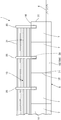
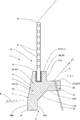
以下、本発明の実施例を添付図面を参照して説明する。図1〜図11は本発明の実施例1を示す。同図に示すように、防護柵1は、山2側の斜面3と道路4などとの境である設置場所5の長さ方向に沿ってコンクリート製の基礎6が設けられる。この基礎6は、プレキャストコンクリート製の単位基礎体である基礎ブロック7を設置場所5の左右長さ方向に並設すると共に連結してなる。
Embodiments of the present invention will be described below with reference to the accompanying drawings. 1 to 11
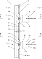
前記基礎ブロック7は、設置場所5の長さ方向の平板部11と、平板部11の山2側(後側)に設けた控え部12とを一体に備える。また、平板部11は反山2側(前側)に傾斜面部13を有し、上面部14は平坦で、上面部14の山側には略垂直な防護面部15が設けられ、図2に示すように、前記控え部12は、平板部11の長さ方向中央で平面において平板部11に直交して設けられている。また、控え部12の左右の側面部16,16は略平行に形成され、左右の側面部16,16の前側と前記防護面部15,15の角部には、傾斜状の肉盛り部17,17が設けられている。
The
前記平板部11の下部に根入れ部18を設け、この根入れ部18は断面略方形をなし、反山2側の面である前面部18Mは垂直で、この前面部18Mは前記傾斜面部13に連続し、根入れ部18の山2側の面である後面部18Uは垂直で前記防護面部15より後方に位置する。即ち、根入れ部18の前後厚さは、前記平板部11の底部の前後厚さよりも厚い。そして、隣り合う基礎ブロック7,7の長さ方向の端面7T,7Tを突き合わせて複数の基礎ブロック7,7・・・を並べる。また、根入れ部18は地中に埋設し、根入れ部18の上部を道路4の上面に合わせる。
A
前記控え部12は、前側に支柱取付部21が設けられると共に、後側に前記支柱取付部21より一段低いアンカー取付部22を設けられている。前記支柱取付部21の上面部21Jは前記上面部14と面一であり、前記上面部21Jと前記アンカー取付部22の上面部22Jとの間には略垂直な後面部21Uが設けられている。また、アンカー取付部22の下面部22Kは略水平に形成され、さらに、前記下面部21Kと前記後面部21Uの上端との間は、後側に向かって高くなる下面部21Kが設けられ、この下面部21Kは前記支柱取付部21の下部に設けられている。
The holding
図3などに示すように、前記平板部11には横鋼材23を挿通する挿通孔部24,24が上下に並んで複数形成されている。また、図2及び図3に示すように、前記支柱取付部21には、支柱25を取り付ける取付孔部26が穿設されている。さらに、前記アンカー取付部22は、アンカー手段27を挿通する挿通孔部28を穿設している。尚、アンカー手段27には、全ネジPC鋼棒などが例示される。また、アンカー手段27の下端は、十分な反力が得られる地山に固定される。
As shown in FIG. 3 and the like, a plurality of insertion holes 24, 24 through which the
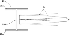
前記支柱25にはH形鋼が用いられている。この支柱25は、前後のフランジ部25A,25Aの中央を、これらと交差方向のウエブ部25Bにより連結し、左右には取付用の溝部25C,25Cが縦設されている。また、隣り合う支柱25,25間には防護部材が設けられ、この例の防護部材は、梁である横部材31であって、横部材31の本体32は、硬質材料からなる鋼製などの角パイプからなる。また、前記横部材31は支柱25,25間に上下に間隔を置いて多段に設けられる。
An H-section steel is used for the
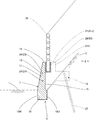
前記支柱25には、前記横部材31の端部が角度調整取付構造33により取り付けられ、以下、その角度調整取付構造33の構成について説明する。
The end of the
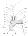
前記角度調整取付構造33は、前記横部材31の端部に設けた連結部材34と、前記支柱25に設けた支柱側受け部材35とを備える。
The angle
前記横部材31の端部にH形鋼36の一方のフランジ部36Aを溶着などにより固定し、前記一方のフランジ部36Aの外面と横部材31の外面とに、複数の補強用リブ部37を取り付ける。そして、前記H形鋼の他方のフランジ部36Bとウエブ部36Cとにより前記連結部材34を構成し、ウエブ部36Cにより横部材側挿入連結部を構成し、ウエブ部36Cは縦板部である。また、フランジ部36Bは、横部材31の長さ方向の抜け止め部であって、ウエブ部36Cが左右方向において後述する縦溝部44から抜けることを防止する。
One
前記支柱側受け部材35は、前記溝部25Cに固定する平板状の横材41と、前記溝部25Cから外部に突出した横材41の先端に設けられた縦材42とを一体に備え、横材41は支柱25に取付けられる取付部である。前記横材41の幅方向両側縁には、前記フランジ部25Aの内面に配置する凹部43,43が設けられ、両側の凹部43,43が前後のフランジ部25A,25A内に嵌った状態で溶着などにより支柱25に固定されている。尚、フランジ部25A,25Aの外面と横材41の先端側の側縁とは面一になる。
The column-
前記縦材42の前後方向中央には、上部が開口した縦溝部44が縦設され、前記縦溝部44の上部の両側には上方に向かって間隔が広がる縦溝傾斜縁部44A,44Aが設けられ、縦溝部44に前記ウエブ部36Cが上方から遊挿される。そして、縦溝部44の下部側の幅Hの寸法は前記ウエブ部36Cの厚さTの寸法よりも大きい。また、縦材42の前後上部には、透孔45,45が穿設されている。
A
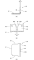
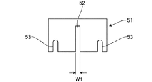
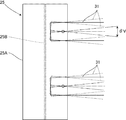
また、前記縦溝部44の上部を塞ぐ板状の閉塞部材51を備え、この閉塞部材51は前記縦溝部44に対応し下部が開口した下縦溝部52と、前後の前記透孔45,45に対応し下部が開口した前後の切欠き長孔部53,53とを備える。そして、下縦溝部52の幅W1の寸法は前記厚さTの寸法より大きく、且つ前記幅Wの寸法より小さい(W>W1>T)。例えば、幅Wは30mm、幅H1は20mm、厚さTは12mm程度である。また、縦材42と閉塞部材51の厚さT1の寸法は、前記厚さTの寸法以上で、前記幅W1の寸法以下である。即ち、幅Wが厚さTより大きくても、厚さT1が大きくなると、支柱25の左右方向の調整可能な角度θが小さくなるため、厚さT1の寸法を前記幅W1の寸法以下とした。また、両端のフランジ部36B,36Bの外面の間隔Kは、隣り合う支柱25,25のウエブ部25B,25Bの外面の間隔KWより小さく、隣りある支柱25,25の縦材42,42の内面の間隔KTより大きい。また、上記の寸法で、厚さT1が14mmの場合、図11に示すように、支柱25の左右方向の調整可能な角度θは5.736度であり、また、図10に示すように、支柱25の上下方向の調整を想定する角度θVは11.422度である。
In addition, a plate-
さらに、上下に隣り合う横材41の底面と縦材42の上端との間隔Hは、前記ウエブ部36Cの高さHWの寸法より大きい。従って、支柱25の前後一側から前記間隔Hにウエブ部36Cを遊挿し、ここから横部材31を下して前記縦溝部44にウエブ部36Cを遊挿することができる。
Further, the distance H between the bottom surface of the
ここで前記支柱25への横部材31の取付方法について説明する。工場において、支柱25には前記支柱側受け部材35が上下多段に取付けられており、また、工場において、横部材31の両端には前記連結部材34が取り付けられている。そして、下段側から横部材31を取り付け、上述したようにして、支柱25の前後一側から前記間隔Hにウエブ部36Cを遊挿し、ここから横部材31を下して両端のウエブ部36C,36Cを両側の支柱25,25の縦溝部44,44に遊挿する。この状態で縦溝部44とウエブ部36Cの間にその寸法差による隙間があるため、縦材42に対してウエブ部36Cの左右方向の向きを調整することができ、また、縦材42に対してウエブ部36Cの上下方向の向きを調整することができる。
Here, a method of attaching the
このように必要に応じて現場の勾配に合わせて横部材31を配置した後、前記ウエブ部36Cの上部に下縦溝部52を外嵌するようにして縦材42の外面に閉塞部材51を重ね合わせ、切欠き長孔部53と透孔45に、固定手段たるボルト54を挿通し、ボルト54にナット54Aを螺合して縦材42に閉塞部材51を固定する。これにより縦材42からウエブ部36Cが外れることなく、支柱25に横部材31の端部を固定することができる。また、閉塞部材51には切欠き長孔部53が形成されているから、縦材42に対してウエブ部36Cの上下方向の向きの角度が大きくなっても、縦材42に閉塞部材51を固定することができる。
As described above, after the
次に、施工方法について説明する。隣り合う基礎ブロック7,7の長さ方向の端面7T,7Tを突き合わせて複数の基礎ブロック7,7・・・を並べ、根入れ部18は地中に埋設し、複数の基礎ブロック7,7・・・の挿通孔部24,24に横鋼材23,23を挿通し、この横鋼材23,23により複数の基礎ブロック7,7・・・を緊張一体化して基礎6を構築し、山側のアンカー取付部22をアンカー手段27により山2側の地山に固定し、所定の支持力を得る。尚、図1において右端の基礎ブロック7は、平板部11の右側が無いものである。さらに、勾配に対応して、基礎ブロック7の端面7Tを斜めに形成する。この場合は、工場で端面7Tを斜めに成形したり、工場又は現場で端面7Tを切断などにより斜めに加工してもよい。
Next, a construction method will be described. A plurality of foundation blocks 7, 7... Are arranged by abutting the end faces 7T, 7T in the length direction of adjacent foundation blocks 7, 7, and the
また、支柱取付部21に支柱25の下部を挿入配置し、その支柱取付部21に無収縮モルタルなどの充填材55を入れ、支柱25を固定する。この後、上述したように隣り合う支柱25,25間に横部材31を多段に設ける。
Further, the lower portion of the
この防護柵1においては、斜面3の積雪が防護面部15と基礎6の後面部21Uに加わると、基礎6全体により支持すると共に、山2側のアンカー手段27が対抗することにより、安定した支持力が得られる。
In this
このように本実施例では、請求項1に対応して、防護柵1の支柱25に横部材31を角度調整可能に取付ける横部材の取付構造であって、横部材31を上下に角度調整可能であるから、設置場所5の勾配に対応して横部材31を取り付けることができる。
As described above, in this embodiment, in accordance with the first aspect of the present invention, the
このように本実施例では、請求項2に対応して、横部材31が前後に角度調整可能であるから、設置場所5の縦断及び横断の勾配や平面線形に対応して横部材31を取り付けることができる。
As described above, in this embodiment, the
このように本実施例では、請求項3に対応して、支柱25側に設けられた支柱側受け部材35と、この支柱側受け部材35に設けられ上部が開口した縦溝部44と、横部材31に設けられ縦溝部44に角度調整可能に遊挿される横部材側挿入連結部たるウエブ部36Cとを備えるから、縦溝部44にウエブ部36Cを遊挿した状態で、横部材31の角度を調整して支柱25に取り付けることができる。
Thus, in the present embodiment, corresponding to claim 3, the column-
このように本実施例では、請求項4に対応して、縦溝部44の上部を塞ぐ閉塞部材51を備えるから、縦溝部44からの横部材側挿入連結部たるウエブ部36Cの抜け出しを防止できる。
Thus, in the present embodiment, corresponding to the fourth aspect, since the closing
このように本実施例では、請求項5に対応して、設置場所5にコンクリート製の基礎6を設け、この基礎6の上に、左右長さ方向に所定間隔をおいて複数の支柱25,25を設け、支柱25,25間に防護部材たる横部材31を設けた防護柵1において、基礎6は、複数のプレキャスト製の単位基礎体たる基礎ブロック7を長さ方向に連結してなり、基礎ブロック7は、平板部11と、この平板部11の前後方向山側に一体に設けた控え部12と、この控え部12を設置場所5に固定するアンカー手段27とを備えるから、複数の基礎ブロック7を設置場所5に並べて連結すると共に、アンカー手段27により固定することにより、所定強度の基礎6が得られ、その基礎6の上に支柱25を立設すると共に、支柱25,25間の横部材31を設けることにより防護柵1を構築することができる。この防護柵1では基礎のプレキャスト製の基礎ブロック7を用いることにより、現場施工の軽減と工場製品による均一な品質が得られる。
Thus, in this embodiment, in accordance with
このように本実施例では、請求項6に対応して、控え部12の箇所に支柱25を立設したから、支柱25を安定して立設することができる。
As described above, in this embodiment, since the
このように本実施例では、請求項7に対応して、控え部12は、支柱25を取り付ける支柱取付部21と、この支柱取付部21の山側で該支柱取付部21より低く形成され、アンカー手段27を取り付けるアンカー取付部22とを備えるから、支柱25を高い位置に固定し、山2側の低い位置でアンカー手段27により基礎ブロック7を設置場所5に固定することができる。
Thus, in this embodiment, corresponding to claim 7, the holding
このように本実施例では、防護部材が横部材31であり、横部材31は隣り合う支柱25,25間に多段に設けられ、横部材31を支柱25に角度調整可能に取付ける角度調整取付構造33を有するから、設置場所5の勾配に対応して横部材31を取り付けることができる。
As described above, in this embodiment, the protective member is the
以下、実施例上の効果として、角度調整取付構造33は剛結ではなく、ピン結合であるから、取付け箇所に無理な力が加わらない。また、アンカー手段27を支柱25及び後面部21Uと離れた山2側に配置したから、アンカー手段27により積雪荷重や落石荷重を効果的に支持することできる。さらに、上下に隣り合う横材41の底面と縦材42の上端との間隔Hは、前記ウエブ部36Cの高さHWの寸法より大きいから、支柱25の前後一側から前記間隔Hにウエブ部36Cを遊挿し、ここから横部材31を下して前記縦溝部44にウエブ部36Cを遊挿することができる。また、閉塞部材51は縦溝部44に対応し下部が開口した下縦溝部52と、前後の透孔45,45に対応し下部が開口した前後の切欠き長孔部53,53とを備えるから、下縦溝部52によりウエブ部36Cが縦溝部44から外れることなく連結でき、さらに、横部材31に縦断方向の勾配がある場合も、切欠き長孔部53,53により閉塞部材51を縦材42に固定することができる。
Hereinafter, as an effect of the embodiment, the angle
図11は本発明の実施例2を示し、上記実施例1と同一部分に同一符号を付し、その説明を省略して詳述すると、この例では、斜面3の傾斜角が60度の現場に設ける防護柵1であり、控え部12のアンカー取付部22の前後方向を前記実施例1のものより短く形成している。尚、実施例1では、斜面3の傾斜角が50度のタイプのものを示した。
FIG. 11 shows a second embodiment of the present invention. The same reference numerals are given to the same portions as those in the first embodiment, and the description thereof will be omitted. In this example, the slope 3 has an inclination angle of 60 degrees. The front and rear direction of the
このように本実施例では、上記実施例1と同様な作用・効果を奏する。 As described above, in this embodiment, the same operations and effects as those of the first embodiment are obtained.
また、このように、斜面3の傾斜角が大きくなったら、アンカー取付部22の前後長さ方向を変更し、他は変更しないで対応することができる。
In addition, when the inclination angle of the slope 3 increases as described above, it is possible to cope with the change in the longitudinal direction of the
図12は本発明の実施例3を示し、上記各実施例と同一部分に同一符号を付し、その説明を省略して詳述すると、この例では、斜面3の傾斜角が40度の現場に設ける防護柵1であり、控え部12のアンカー取付部22の前後方向を前記実施例1のものより長く形成している。
FIG. 12 shows a third embodiment of the present invention. The same reference numerals are given to the same parts as those of the above-described embodiments, and the description thereof will be omitted. In this example, the slope 3 has an inclination angle of 40 degrees. The front and rear direction of the
このように本実施例では、上記各実施例と同様な作用・効果を奏する。 As described above, in this embodiment, the same operations and effects as the above-described embodiments are obtained.
また、このように、斜面3の傾斜角が小さくなったら、アンカー取付部22の前後長さ方向を変更し、具体的には傾斜角が角度が減少したら、アンカー取付部22の前後寸法を逆に長く形成し、また、傾斜角が角度が増加したら、アンカー取付部22の前後寸法を逆に短く形成し、他は変更しないで対応することができる。
As described above, when the inclination angle of the inclined surface 3 is reduced, the longitudinal direction of the
図13は本発明の実施例4を示し、上記各実施例と同一部分に同一符号を付し、その説明を省略して詳述すると、この例では、上記実施例1〜3が設計積雪深さが同じであったのに対して、実施例1〜3より設計積雪深さが深い現場に設ける防護柵1である。
FIG. 13 shows a fourth embodiment of the present invention. The same reference numerals are given to the same parts as those of the above-described embodiments, and the description thereof will be omitted. It is the
実施例1〜3に比べて、支柱25の高さと防護面部15の高さを大きくし、横部材31の段数も増やしており、他は変更しないで対応できる。
Compared with the first to third embodiments, the height of the
このように本実施例では、上記各実施例1と同様な作用・効果を奏する。 As described above, in this embodiment, the same operations and effects as those of the first embodiment are obtained.
また、この例でも、上記実施例と同様に斜面3の傾斜角が小さくなったら、アンカー取付部22の前後長さ方向を変更し、具体的には傾斜角が角度が減少したら、アンカー取付部22の前後寸法を逆に長く形成し、また、傾斜角が角度が増加したら、アンカー取付部22の前後寸法を逆に短く形成し、他は変更しないで対応することができる。
Also in this example, when the inclination angle of the slope 3 becomes small as in the above embodiment, the longitudinal direction of the
尚、本発明は、本実施例に限定されるものではなく、本発明の要旨の範囲内で種々の変形実施が可能である。例えば、実施例では、T型の連結部材を用いたが、L型でもよく、抜け止め部の形状は適宜選定可能である。また、単位基礎体に複数の控え部を設け、各控え部にアンカー手段を設けてもよい。さらに、支柱を上段側から取り付けてもよい。また、支柱をH形鋼にすることにより連結部材を取付け易くなるが、これに限定されず、支柱を円形の鋼管や角形の鋼管などにしてもよい。さらに、根入れ部は必ずしも設ける必要はない。 The present invention is not limited to this embodiment, and various modifications can be made within the scope of the gist of the present invention. For example, in the embodiment, a T-shaped connecting member is used, but an L-shaped connecting member may be used, and the shape of the retaining portion can be appropriately selected. Further, a plurality of holding portions may be provided on the unit base body, and anchor means may be provided on each holding portion. Furthermore, you may attach a support | pillar from the upper stage side. Moreover, although it becomes easy to attach a connection member by making a support | pillar into H-section steel, it is not limited to this, You may make a support | pillar into a circular steel pipe, a square steel pipe, etc. Further, it is not always necessary to provide the root portion.
1 防護柵
2 山
3 斜面
5 設置場所
6 基礎
7 基礎ブロック(単位基礎体)
11 平板部
12 控え部
21 支柱取付部
22 アンカー取付部
27 アンカー手段
31 横部材(防護部材)
33 角度調整取付構造
34 連結部材
35 支柱側受け部材
36C ウエブ部 (横部材側挿入連結部)
44 縦溝部
51 閉塞部材
DESCRIPTION OF
33 Angle
44
Claims (7)
設置場所にコンクリート製の基礎を設け、この基礎の上に、左右長さ方向に所定間隔をおいて複数の支柱を設け、前記支柱間に前記横部材を設け、
前記基礎は、複数のプレキャスト製の単位基礎体を長さ方向に連結してなり、前記単位基礎体は、平板部と、この平板部の前後方向山側に一体に設けた控え部と、この控え部を前記設置場所に固定するアンカー手段とを備えることを特徴とする防護柵。 The mounting structure of the transverse member according to any one of claims 1 to 4,
A concrete base is provided at the installation location, and on this foundation, a plurality of support posts are provided at predetermined intervals in the left-right length direction, and the transverse member is provided between the support posts,
The foundation is formed by connecting a plurality of precast unit foundation bodies in the length direction. The unit foundation body includes a flat plate portion, a holding portion integrally provided on the front and rear mountain side of the flat plate portion, and the holding portion. And an anchor means for fixing the part to the installation location.
Priority Applications (1)
| Application Number | Priority Date | Filing Date | Title |
|---|---|---|---|
| JP2016084142A JP2017193857A (en) | 2016-04-20 | 2016-04-20 | Attachment structure of transverse member and guard fence |
Applications Claiming Priority (1)
| Application Number | Priority Date | Filing Date | Title |
|---|---|---|---|
| JP2016084142A JP2017193857A (en) | 2016-04-20 | 2016-04-20 | Attachment structure of transverse member and guard fence |
Publications (1)
| Publication Number | Publication Date |
|---|---|
| JP2017193857A true JP2017193857A (en) | 2017-10-26 |
Family
ID=60155404
Family Applications (1)
| Application Number | Title | Priority Date | Filing Date |
|---|---|---|---|
| JP2016084142A Pending JP2017193857A (en) | 2016-04-20 | 2016-04-20 | Attachment structure of transverse member and guard fence |
Country Status (1)
| Country | Link |
|---|---|
| JP (1) | JP2017193857A (en) |
Cited By (3)
| Publication number | Priority date | Publication date | Assignee | Title |
|---|---|---|---|---|
| JP2021188296A (en) * | 2020-05-27 | 2021-12-13 | ディガードエンジニアリング株式会社 | Protective facility |
| JP7421835B1 (en) | 2023-10-04 | 2024-01-25 | 株式会社プロテックエンジニアリング | protective fence |
| JP7509481B1 (en) | 2024-01-11 | 2024-07-02 | 株式会社プロテックエンジニアリング | Retaining wall protection fence and construction method thereof |
Citations (12)
| Publication number | Priority date | Publication date | Assignee | Title |
|---|---|---|---|---|
| JPS4525067Y1 (en) * | 1965-10-07 | 1970-10-01 | ||
| JPS4635547Y1 (en) * | 1967-09-22 | 1971-12-07 | ||
| JPS4811636U (en) * | 1971-06-21 | 1973-02-09 | ||
| JPS5181443A (en) * | 1975-01-13 | 1976-07-16 | Seiki Kogyo Kk | KUMITATESAKU |
| JPH0620518U (en) * | 1992-04-21 | 1994-03-18 | 東和工業株式会社 | Composition mechanism for construction fences, etc. |
| JP2003082620A (en) * | 2001-09-14 | 2003-03-19 | Shibata Ind Co Ltd | Retaining wall structure |
| US20070224021A1 (en) * | 2006-03-27 | 2007-09-27 | G. S.R.L. | Rapid-assembly earth retaining device |
| JP2008150822A (en) * | 2006-12-15 | 2008-07-03 | Ibigawa Concrete Kogyo Kk | Protective barrier against avalanche or rock fall, sound-insulating wall, support and precast concrete block for protective barrier or sound-insulating wall |
| JP2012052359A (en) * | 2010-09-02 | 2012-03-15 | Sekisui Jushi Co Ltd | Guard fence and attaching metal fitting for guard fence |
| JP2012193556A (en) * | 2011-03-17 | 2012-10-11 | Shinko Kenzai Ltd | Avalanche preventive structure |
| JP2013185357A (en) * | 2012-03-08 | 2013-09-19 | Kcon Kk | Partition structure |
| JP2014101699A (en) * | 2012-11-20 | 2014-06-05 | Protec Engineering Co Ltd | Guard body and construction method thereof |
-
2016
- 2016-04-20 JP JP2016084142A patent/JP2017193857A/en active Pending
Patent Citations (12)
| Publication number | Priority date | Publication date | Assignee | Title |
|---|---|---|---|---|
| JPS4525067Y1 (en) * | 1965-10-07 | 1970-10-01 | ||
| JPS4635547Y1 (en) * | 1967-09-22 | 1971-12-07 | ||
| JPS4811636U (en) * | 1971-06-21 | 1973-02-09 | ||
| JPS5181443A (en) * | 1975-01-13 | 1976-07-16 | Seiki Kogyo Kk | KUMITATESAKU |
| JPH0620518U (en) * | 1992-04-21 | 1994-03-18 | 東和工業株式会社 | Composition mechanism for construction fences, etc. |
| JP2003082620A (en) * | 2001-09-14 | 2003-03-19 | Shibata Ind Co Ltd | Retaining wall structure |
| US20070224021A1 (en) * | 2006-03-27 | 2007-09-27 | G. S.R.L. | Rapid-assembly earth retaining device |
| JP2008150822A (en) * | 2006-12-15 | 2008-07-03 | Ibigawa Concrete Kogyo Kk | Protective barrier against avalanche or rock fall, sound-insulating wall, support and precast concrete block for protective barrier or sound-insulating wall |
| JP2012052359A (en) * | 2010-09-02 | 2012-03-15 | Sekisui Jushi Co Ltd | Guard fence and attaching metal fitting for guard fence |
| JP2012193556A (en) * | 2011-03-17 | 2012-10-11 | Shinko Kenzai Ltd | Avalanche preventive structure |
| JP2013185357A (en) * | 2012-03-08 | 2013-09-19 | Kcon Kk | Partition structure |
| JP2014101699A (en) * | 2012-11-20 | 2014-06-05 | Protec Engineering Co Ltd | Guard body and construction method thereof |
Cited By (4)
| Publication number | Priority date | Publication date | Assignee | Title |
|---|---|---|---|---|
| JP2021188296A (en) * | 2020-05-27 | 2021-12-13 | ディガードエンジニアリング株式会社 | Protective facility |
| JP7421835B1 (en) | 2023-10-04 | 2024-01-25 | 株式会社プロテックエンジニアリング | protective fence |
| JP2025063520A (en) * | 2023-10-04 | 2025-04-16 | 株式会社プロテックエンジニアリング | Protective fence |
| JP7509481B1 (en) | 2024-01-11 | 2024-07-02 | 株式会社プロテックエンジニアリング | Retaining wall protection fence and construction method thereof |
Similar Documents
| Publication | Publication Date | Title |
|---|---|---|
| US20150225917A1 (en) | Structural foundation | |
| KR20190036591A (en) | Thrust pile with prestress and self-supporting type pile construction using it | |
| JP4427690B2 (en) | Construction method of avalanche / falling rock protection fence or soundproof wall, precast concrete block constituting upper part of retaining wall or foundation block, and temporary fixing member of column used for construction of avalanche / falling rock protection fence or soundproof wall | |
| US20140224751A1 (en) | Solar panel mounting stand | |
| KR101287687B1 (en) | Wall construction structure in which wale angle is adjustable and wale for fixing tension cable for the same | |
| JP2017193857A (en) | Attachment structure of transverse member and guard fence | |
| KR101436119B1 (en) | Holding apparatus for CFT column and the construction method of the CFT column using it | |
| EP3420138B1 (en) | Anchoring device for a fence | |
| KR20130023331A (en) | Wall construction structure in which wale angle is adjustable | |
| KR101428540B1 (en) | Soundproof walls basis structure | |
| JP6192972B2 (en) | Calvert | |
| KR102309544B1 (en) | Connecting structure of beam and column of a building and method of manufacturing using the same | |
| KR101127475B1 (en) | Device for connecting wales | |
| KR101619330B1 (en) | Horizontal Beam Supporting Bracket for Temporary Soil Retaining Work | |
| JP3612600B2 (en) | Unit anchor and structural steel foundation beam | |
| KR102604871B1 (en) | Method for forming retaining wall using impermeable wall and earth anchor | |
| JP5215024B2 (en) | Steel frame installation device, retaining wall, and method for constructing retaining wall | |
| JP2010077656A (en) | Structure and method for seismically strengthening column | |
| US12297617B2 (en) | Anchoring device | |
| KR101495318B1 (en) | Civil and building structures for mounting support | |
| KR20040051182A (en) | Temporary soil sheathing using prestress and pile thereof | |
| KR20210098162A (en) | Under ground structure using column steel pipe wall and construction method thereof | |
| KR101881075B1 (en) | Constructing Method of Support Part for Pipe | |
| KR102144108B1 (en) | Retaining wall construction structure using prestressed concrete and method thereof | |
| JP3208100U (en) | Scaffolding device for construction of underground structures |
Legal Events
| Date | Code | Title | Description |
|---|---|---|---|
| A621 | Written request for application examination |
Free format text: JAPANESE INTERMEDIATE CODE: A621 Effective date: 20190401 |
|
| A977 | Report on retrieval |
Free format text: JAPANESE INTERMEDIATE CODE: A971007 Effective date: 20191220 |
|
| A131 | Notification of reasons for refusal |
Free format text: JAPANESE INTERMEDIATE CODE: A131 Effective date: 20200114 |
|
| RD02 | Notification of acceptance of power of attorney |
Free format text: JAPANESE INTERMEDIATE CODE: A7422 Effective date: 20200219 |
|
| A521 | Request for written amendment filed |
Free format text: JAPANESE INTERMEDIATE CODE: A821 Effective date: 20200219 |
|
| A02 | Decision of refusal |
Free format text: JAPANESE INTERMEDIATE CODE: A02 Effective date: 20200804 |