JP2017193423A - Image formation apparatus - Google Patents
Image formation apparatus Download PDFInfo
- Publication number
- JP2017193423A JP2017193423A JP2016085511A JP2016085511A JP2017193423A JP 2017193423 A JP2017193423 A JP 2017193423A JP 2016085511 A JP2016085511 A JP 2016085511A JP 2016085511 A JP2016085511 A JP 2016085511A JP 2017193423 A JP2017193423 A JP 2017193423A
- Authority
- JP
- Japan
- Prior art keywords
- air
- paper
- unit
- image forming
- forming apparatus
- Prior art date
- Legal status (The legal status is an assumption and is not a legal conclusion. Google has not performed a legal analysis and makes no representation as to the accuracy of the status listed.)
- Granted
Links
Images


Classifications
-
- B—PERFORMING OPERATIONS; TRANSPORTING
- B65—CONVEYING; PACKING; STORING; HANDLING THIN OR FILAMENTARY MATERIAL
- B65H—HANDLING THIN OR FILAMENTARY MATERIAL, e.g. SHEETS, WEBS, CABLES
- B65H5/00—Feeding articles separated from piles; Feeding articles to machines
- B65H5/22—Feeding articles separated from piles; Feeding articles to machines by air-blast or suction device
-
- B—PERFORMING OPERATIONS; TRANSPORTING
- B65—CONVEYING; PACKING; STORING; HANDLING THIN OR FILAMENTARY MATERIAL
- B65H—HANDLING THIN OR FILAMENTARY MATERIAL, e.g. SHEETS, WEBS, CABLES
- B65H9/00—Registering, e.g. orientating, articles; Devices therefor
- B65H9/002—Registering, e.g. orientating, articles; Devices therefor changing orientation of sheet by only controlling movement of the forwarding means, i.e. without the use of stop or register wall
-
- B—PERFORMING OPERATIONS; TRANSPORTING
- B65—CONVEYING; PACKING; STORING; HANDLING THIN OR FILAMENTARY MATERIAL
- B65H—HANDLING THIN OR FILAMENTARY MATERIAL, e.g. SHEETS, WEBS, CABLES
- B65H9/00—Registering, e.g. orientating, articles; Devices therefor
- B65H9/004—Deskewing sheet by abutting against a stop, i.e. producing a buckling of the sheet
- B65H9/008—Deskewing sheet by abutting against a stop, i.e. producing a buckling of the sheet the stop being formed by reversing the forwarding means
-
- B—PERFORMING OPERATIONS; TRANSPORTING
- B65—CONVEYING; PACKING; STORING; HANDLING THIN OR FILAMENTARY MATERIAL
- B65H—HANDLING THIN OR FILAMENTARY MATERIAL, e.g. SHEETS, WEBS, CABLES
- B65H9/00—Registering, e.g. orientating, articles; Devices therefor
- B65H9/20—Assisting by photoelectric, sonic, or pneumatic indicators
-
- G—PHYSICS
- G03—PHOTOGRAPHY; CINEMATOGRAPHY; ANALOGOUS TECHNIQUES USING WAVES OTHER THAN OPTICAL WAVES; ELECTROGRAPHY; HOLOGRAPHY
- G03G—ELECTROGRAPHY; ELECTROPHOTOGRAPHY; MAGNETOGRAPHY
- G03G15/00—Apparatus for electrographic processes using a charge pattern
- G03G15/65—Apparatus which relate to the handling of copy material
- G03G15/6555—Handling of sheet copy material taking place in a specific part of the copy material feeding path
- G03G15/6558—Feeding path after the copy sheet preparation and up to the transfer point, e.g. registering; Deskewing; Correct timing of sheet feeding to the transfer point
- G03G15/6561—Feeding path after the copy sheet preparation and up to the transfer point, e.g. registering; Deskewing; Correct timing of sheet feeding to the transfer point for sheet registration
-
- B—PERFORMING OPERATIONS; TRANSPORTING
- B65—CONVEYING; PACKING; STORING; HANDLING THIN OR FILAMENTARY MATERIAL
- B65H—HANDLING THIN OR FILAMENTARY MATERIAL, e.g. SHEETS, WEBS, CABLES
- B65H2404/00—Parts for transporting or guiding the handled material
- B65H2404/10—Rollers
- B65H2404/14—Roller pairs
- B65H2404/142—Roller pairs arranged on movable frame
- B65H2404/1424—Roller pairs arranged on movable frame moving in parallel to their axis
-
- B—PERFORMING OPERATIONS; TRANSPORTING
- B65—CONVEYING; PACKING; STORING; HANDLING THIN OR FILAMENTARY MATERIAL
- B65H—HANDLING THIN OR FILAMENTARY MATERIAL, e.g. SHEETS, WEBS, CABLES
- B65H2406/00—Means using fluid
- B65H2406/30—Suction means
- B65H2406/32—Suction belts
- B65H2406/322—Suction distributing means
- B65H2406/3222—Suction distributing means switchable suction elements
-
- B—PERFORMING OPERATIONS; TRANSPORTING
- B65—CONVEYING; PACKING; STORING; HANDLING THIN OR FILAMENTARY MATERIAL
- B65H—HANDLING THIN OR FILAMENTARY MATERIAL, e.g. SHEETS, WEBS, CABLES
- B65H2406/00—Means using fluid
- B65H2406/30—Suction means
- B65H2406/36—Means for producing, distributing or controlling suction
- B65H2406/365—Means for producing, distributing or controlling suction selectively blowing or sucking
-
- G—PHYSICS
- G03—PHOTOGRAPHY; CINEMATOGRAPHY; ANALOGOUS TECHNIQUES USING WAVES OTHER THAN OPTICAL WAVES; ELECTROGRAPHY; HOLOGRAPHY
- G03G—ELECTROGRAPHY; ELECTROPHOTOGRAPHY; MAGNETOGRAPHY
- G03G2215/00—Apparatus for electrophotographic processes
- G03G2215/00362—Apparatus for electrophotographic processes relating to the copy medium handling
- G03G2215/00535—Stable handling of copy medium
- G03G2215/00679—Conveying means details, e.g. roller
Abstract
Description
本発明は、画像形成装置に関する。 The present invention relates to an image forming apparatus.
従来から、電子写真方式を採用したプリンタや複写機等の画像形成装置が広く利用されている。一般的な画像形成装置では、使用する用紙の種類や性質が様々であることや、搬送ローラー等の部品の特性、搬送時における温度や湿度の使用環境等の要因によって、用紙が搬送方向とは直交する方向(以下、用紙幅方向という)に片寄って搬送されてしまう場合がある。この状態において、印刷処理を実行すると、印字位置精度が低下してしまうという問題があった。 2. Description of the Related Art Conventionally, image forming apparatuses such as printers and copiers that employ an electrophotographic method have been widely used. In general image forming apparatuses, the direction of the paper is the direction of conveyance due to various types and properties of the paper used, the characteristics of parts such as the conveyance rollers, and the usage environment of temperature and humidity during conveyance. In some cases, the sheet is conveyed in a direction perpendicular to the sheet (hereinafter referred to as a sheet width direction). If the printing process is executed in this state, there is a problem that the printing position accuracy is lowered.
そこで、従来から、片寄りセンサにより用紙の幅方向のずれ量を検知し、この検知結果に基づいて用紙をレジストローラー対により挟持した状態で用紙幅方向に移動させることにより、画像に対する用紙の位置関係を調整する、いわゆる片寄り補正(レジスト揺動補正)が行われている。例えば、特許文献1には、用紙のレジストレーションを行うための用紙整合装置に関し、レジストローラーのみによって用紙の整合を行わずに、その上流部に配置するプリレジストローラーにも整合機能を持たせることが記載されている。 Therefore, conventionally, the position of the paper relative to the image is detected by detecting the amount of deviation in the paper width direction by the deviation sensor and moving the paper in the paper width direction while being sandwiched between the registration roller pairs based on the detection result. So-called offset correction (registration swing correction) is performed to adjust the relationship. For example, Patent Document 1 relates to a sheet aligning device for performing sheet registration, and does not perform sheet alignment only by a registration roller, but also has a pre-registration roller disposed in an upstream portion thereof having an alignment function. Is described.
しかしながら、上述した特許文献1に記載される従来の画像形成装置等では、以下のような問題がある。すなわち、レジストローラーとプリレジストローラーとの両方を揺動させるため、揺動時にプリレジストローラーと用紙とが摺れてしまうことはないが、ガイド板と用紙との間では摺れが発生し、その結果、画像品質の低下につながってしまうという問題がある。また、この場合、用紙の揺動の際の抵抗にもなり、揺動精度が低下してしまうという問題もある。さらには、用紙の揺動時において、レジストローラーとプリレジストローラーとの揺動量が少しでもずれた場合には、用紙にストレスが付与され、シワが発生してしまうという問題もある。 However, the conventional image forming apparatus described in Patent Document 1 described above has the following problems. That is, since both the registration roller and the pre-registration roller are swung, the pre-registration roller and the paper do not slide at the time of swinging, but the sliding occurs between the guide plate and the paper, As a result, there is a problem that the image quality is deteriorated. In this case, there is also a problem that the swing accuracy is lowered due to resistance when the paper is swung. Furthermore, when the swinging amount of the registration roller and the pre-registration roller is slightly shifted during the swinging of the paper, there is a problem that stress is applied to the paper and wrinkles are generated.
そこで、本発明は、レジストローラー対によるレジスト揺動補正を行う場合において、画像品質の低下を確実に防止することが可能な画像形成装置を提供することを目的とする。 SUMMARY OF THE INVENTION An object of the present invention is to provide an image forming apparatus capable of reliably preventing a decrease in image quality when performing registration swing correction by a registration roller pair.
本発明に係る画像形成装置は、上記課題を解決するために、用紙を挟持した状態で用紙搬送方向の第1の方向とは直交する第2の方向に揺動するレジストローラー対と、前記レジストローラー対よりも第1の方向の上流側に設けられ、用紙を前記レジストローラー対に搬送する搬送ベルトを有する搬送部と、前記搬送ベルトにより搬送される用紙に対してエアーによる吸引または吹き出しを行う第1のエアー調整部と、前記搬送ベルトにより用紙の搬送を行う場合に前記第1のエアー調整部を制御して用紙をエアーにより吸引する第1の動作と、前記レジストローラー対により用紙の揺動を行う場合に前記第1のエアー調整部を制御して用紙にエアーを吹き付ける第2の動作とを切り替える制御部と、を備えるものである。 In order to solve the above-described problem, an image forming apparatus according to the present invention includes a pair of registration rollers that swing in a second direction perpendicular to the first direction of the paper conveyance direction while sandwiching the paper, and the resist Provided on the upstream side in the first direction with respect to the pair of rollers and having a transport belt for transporting the paper to the pair of registration rollers, and sucking or blowing out air with respect to the paper transported by the transport belt A first air adjusting unit; a first operation of controlling the first air adjusting unit to suck the paper by air when the paper is conveyed by the conveying belt; and a pair of registration rollers to shake the paper. A control unit that controls the first air adjusting unit to switch the second operation of blowing air onto the paper when moving.
本発明によれば、レジスト揺動補正時に用紙を浮上させた状態でレジストローラー対により揺動させるので、用紙がガイド部材や搬送ベルトと擦れることを防止することができる。これにより、画像品質の低下を防止することができる。 According to the present invention, since the sheet is swung by the pair of registration rollers in a state where the sheet is floated at the time of the registration rocking correction, it is possible to prevent the sheet from rubbing against the guide member and the conveyance belt. Thereby, it is possible to prevent a decrease in image quality.
以下に添付図面を参照しながら、本開示の好適な実施の形態について詳細に説明する。なお、図面の寸法比率は、説明の都合上拡張されており、実際の比率と異なる場合がある。 Hereinafter, preferred embodiments of the present disclosure will be described in detail with reference to the accompanying drawings. In addition, the dimension ratio of drawing is expanded on account of description and may differ from an actual ratio.
<第1の実施の形態>
[画像形成装置100の構成例]
図1は、本発明に係る画像形成装置100の構成の一例を示している。図1に示すように、画像形成装置100は、タンデム型の画像形成装置と称されるものであり、自動原稿搬送部80と装置本体102とを備えている。自動原稿搬送部80は、装置本体102の上部に取り付けられ、搬送台上にセットされた用紙を、搬送ローラー等により装置本体102の画像読取部90に送り出す。
<First Embodiment>
[Configuration Example of Image Forming Apparatus 100]
FIG. 1 shows an example of the configuration of an
装置本体102は、操作表示部70と、画像読取部90と、画像形成部10と、中間転写ベルト8と、給紙部20と、搬送部200Aと、レジスト部110と、定着部44と、自動用紙反転搬送ユニット60(Auto Duplex Unit:以下ADUという)とを有している。
The apparatus
操作表示部70は、表示部と入力部とが組み合わされたタッチパネルと、タッチパネルの周辺部に設けられたスタートキーや決定キーを含む複数の操作キーとを有している。操作表示部70は、操作画面等を画面上に表示したり、操作画面でのタッチ操作や操作キーの操作により入力された画像形成条件等の情報を受け付けたりする。
The
画像読取部90は、原稿台上に載置された原稿、または自動原稿搬送部80により搬送された原稿を走査露光装置の光学系により走査露光し、走査した原稿の画像をCCD(Charge Coupled Device)イメージセンサにより光電変換して画像情報信号を生成する。画像情報信号は、図示しない画像処理部によりアナログ処理、アナログ/ディジタル(以下A/Dという)変換処理、シューディング補正、画像圧縮処理等が行われた後に、画像形成部10に出力される。
The
画像形成部10は、電子写真方式により画像を形成するものであり、イエロー(Y)色の画像を形成する画像形成ユニット10Yと、マゼンタ(M)色の画像を形成する画像形成ユニット10Mと、シアン(C)色の画像を形成する画像形成ユニット10Cと、黒(K)色の画像を形成する画像形成ユニット10Kとを有している。この例では、それぞれ共通する機能名称、例えば、符号10の後ろに形成する色を示すY,M,C,Kを付して表記する。
The
画像形成ユニット10Yは、感光体ドラム1Yと、その周囲に配置される帯電器2Y、露光部(光書込み部)3Y、現像器4Yおよびクリーニング部6Yを有している。画像形成ユニット10Mは、感光体ドラム1Mと、その周囲に配置される帯電器2M、露光部3M、現像器4Mおよびクリーニング部6Mを有している。画像形成ユニット10Cは、感光体ドラム1Cと、その周囲に配置される帯電器2C、露光部3C、現像器4Cおよびクリーニング部6Cを有している。画像形成ユニット10Kは、感光体ドラム1Kと、その周囲に配置される帯電器2K、露光部3K、現像器4Kおよびクリーニング部6Kを有している。
The
画像形成ユニット10Y,10M,10C,10Kにおけるそれぞれの感光体ドラム(像担持体)1Y,1M,1C,1K、帯電器2Y,2M,2C,2K、露光部3Y,3M,3C,3K、現像器4Y,4M,4C,4K、クリーニング部6Y,6M,6C,6K、一次転写ローラー7Y,7M,7C,7Kは、それぞれ共通する内容の構成である。以下、特に、区別が必要な場合を除き、Y,M,C,Kを付さずに表記することとする。
Respective photosensitive drums (image carriers) 1Y, 1M, 1C, and 1K in the
帯電器2は、感光体ドラム1の表面をほぼ一様に帯電する。露光部3は、例えばLEDアレイと結像レンズとを有するLPH(LED Print Head)や、ポリゴンミラー方式のレーザー露光走査装置により構成され、画像情報信号に基づいて感光体ドラム1上をレーザー光により走査して静電潜像を形成する。現像器4は、感光体ドラム1上に形成された静電潜像をトナーにより現像する。これにより、感光体ドラム1上に可視画像であるトナー像が形成される。 The charger 2 charges the surface of the photosensitive drum 1 almost uniformly. The exposure unit 3 is composed of, for example, an LPH (LED Print Head) having an LED array and an imaging lens, or a polygon mirror type laser exposure scanning device, and the photosensitive drum 1 is irradiated with laser light based on an image information signal. Scan to form an electrostatic latent image. The developing device 4 develops the electrostatic latent image formed on the photosensitive drum 1 with toner. As a result, a toner image which is a visible image is formed on the photosensitive drum 1.
中間転写ベルト8は、複数のローラーにより張架されると共に回動可能に支持されている。中間転写ベルト8の回動と併せて、一次転写ローラー7と感光体ドラム1とが回転し、一次転写ローラー7と感光体ドラム1との間に所定の電圧が印加されることで、感光体ドラム1に形成されたトナー像が中間転写ベルト8上に転写される(一次転写)。
The
給紙部20は、A3やA4等の用紙Pが収容された複数の給紙トレイ20A,20Bを有している。各給紙トレイ20A,20Bから搬送ローラー22,24,26,28等によって搬送された用紙Pは、搬送部200A、レジスト部110に搬送される。なお、給紙トレイの数は2つに限定されるものではない。また、必要に応じて大容量の用紙Pを収容することが可能な大容量給紙装置を単数または複数連結させても良い。
The
レジスト部110に搬送された用紙Pは、搬送部200Aの搬送によってレジストローラー対120に突き当てられることで用紙Pの曲りが補正される。用紙Pの曲がりが補正された用紙Pは、所定のタイミングで二次転写部34に搬送される。二次転写部34では、中間転写ベルト8上に転写されたY色、M色、C色、K色トナー像が、レジストローラー対120により搬送される用紙Pの表面に一括転写される(二次転写)。二次転写された用紙Pは、用紙搬送方向D1の下流側の定着部44に搬送される。
The paper P conveyed to the
定着部44は、加圧ローラーと加熱ローラーとを有している。定着部44は、二次転写部34でトナー像が転写された用紙Pに加圧、加熱処理を行うことにより用紙Pの表面のトナー像を用紙Pに定着させる。
The fixing
搬送路切替部48は、定着部44の用紙搬送方向D1の下流側に設けられ、選択されている印刷モード(片面印刷モード、両面印刷モード等)に基づいて搬送経路の切り替え制御を行う。片面印刷モードで片面の印刷が終了した用紙P、または、両面印刷モードで両面の印刷が終了した用紙Pは、排紙ローラー46により排紙トレイ上に排出される。
The conveyance
また、両面印刷モードで、用紙Pの裏面側に画像を形成する場合、表面側に画像が形成された用紙Pは、搬送ローラー62等を介してADU60に搬送される。ADU60のスイッチバック経路では、ADUローラー64の逆回転制御により用紙Pの後端を先頭にしてUターン経路部に搬送され、Uターン経路部に設けられた搬送ローラー66,68等により表裏反転された状態で二次転写部34に再給紙される。
Further, when an image is formed on the back side of the paper P in the duplex printing mode, the paper P on which the image is formed on the front side is conveyed to the
[レジスト部110および搬送部200Aの構成例]
図2は、第1の実施の形態に係るレジスト部110および搬送部200Aの構成の一例を示す側面図である。図3は、搬送経路Rの下側の搬送部200Aの構成の一例を示す平面図である。図4は、搬送経路Rの上側の搬送部200Aの構成の一例を示す平面図である。
[Configuration Example of
FIG. 2 is a side view showing an example of the configuration of the resist
図2に示すように、レジスト部110は、レジストローラー対120と、片寄り検知センサ130とを有している。レジストローラー対120は、二次転写部34よりも用紙搬送方向D1の上流側に配置され、用紙Pの先端突き当てによるループの作成により用紙Pの曲がり補正をしたり、用紙再搬送後の用紙先端と画像先端との合わせ補正をしたり、用紙Pを挟持した状態で用紙幅方向D2に揺動させて用紙Pの片寄り補正をしたりする。レジストローラー対120は、回転駆動する駆動ローラー122と、従動回転する従動ローラー124とから構成されている。
As shown in FIG. 2, the
片寄り検知センサ130は、レジストローラー対120よりも用紙搬送方向D1の下流側に配置されている。片寄り検知センサ130は、複数の光電変換素子を用紙幅方向D2に沿って直線状に配列したラインセンサ、又は光電変換素子をマトリクス状に配置したイメージセンサにより構成することができる。ラインセンサ及びイメージセンサとしては、CCD型のイメージセンサやCMOS型(MOS型を含む)のイメージセンサを利用できる。
The
搬送部200Aは、レジスト部110よりも用紙搬送方向D1の上流側に配置され、搬送ローラー220,222と搬送ベルト210とエアー調整部230,330とを有している。搬送ローラー220,222は、搬送経路Rの下方側に一定の間隔をあけて配置されている。本例では、搬送ローラー220および搬送ローラー222のうち少なくとも一方が駆動ローラーで構成される。
The
搬送ベルト210は、無端状のベルト部材であって、搬送ローラー220,222によって張架されている。搬送ベルト210は、搬送ローラー220の回転に伴って回転し、用紙Pを用紙搬送方向D1に沿って搬送する。搬送ベルト210には、エアーを吹き出したり、エアーを吸い込んだりするための多数の貫通孔212が形成されている(図3参照)。貫通孔212は、例えば平面的に見て円形状からなる。
The
図3に示すように、エアー調整部230は、用紙Pに対する搬送経路Rの下方側からのエアーの状態を調整するものであり、給気ファン240と吸引ファン250とダクト260とを有している。給気ファン240は、搬送ベルト210の貫通孔212からエアーを吹き出することにより用紙Pを搬送ベルト210から浮上させた状態で搬送する。吸引ファン250は、搬送ベルト210の貫通孔212からエアーを吸い込むことにより用紙Pを搬送ベルト210に吸着させた状態で搬送する。
As shown in FIG. 3, the
ダクト260は、給気用ダクト262と、吸引用ダクト264と、共通ダクト266とから構成されている。給気用ダクト262は、一端部が給気ファン240に接続され、他端部が共通ダクト266に接続されている。吸引用ダクト264は、一端部が吸引ファン250に接続され、他端部が共通ダクト266に接続されている。共通ダクト266は、一端部が給気用ダクト262および吸引用ダクト264のそれぞれに接続され、他端部が搬送ベルト210の内側まで延在している。共通ダクト266の他端部は開口しており、その開口が上方側の搬送ベルト210に向くように形成されている。
The
風路切替部材270は、給気用ダクト262と吸引用ダクト264との間の境界部に設けられ、用紙Pの処理状態に応じて給気用ダクト262および吸引用ダクト264のそれぞれの風路を開放したり閉塞したりする。風路切替部材270の駆動には、例えばソレノイド等を用いることができる。
The air
図2および図4に示すように、エアー調整部330は、エアー調整部230とは搬送経路Rを挟んで対向して(反対側)設けられ、用紙Pに対する搬送経路Rの上方側からのエアーの状態を調整する。エアー調整部330は、給気ファン340と、ダクト360とを有している。給気ファン340は、用紙Pの上方からエアーを吹き出すことにより、用紙Pを搬送ベルト210側に付勢する。これにより、搬送経路Rの下方側からのエアーにより用紙Pを浮上させた場合は一定の高さに維持された状態で、用紙Pを搬送ベルト210に吸着させた場合は確実な吸着状態で搬送される。
As shown in FIGS. 2 and 4, the
ダクト360は、一端部が給気ファン340に接続され、他端部がガイド部材150の上方であって搬送ベルト210に対応した位置まで延在している。ダクト360の他端部は開口しており、その開口が下方側に設けられたガイド部材150に向くように形成されている。ガイド部材150には、上述した搬送ベルト210と同様に、エアーを吹き出すための多数の貫通孔152が形成されている。貫通孔152は、例えば平面的に見て円形状からなる。
The
[画像形成装置100のブロック構成例]
図5は、画像形成装置100の機能構成の一例を示すブロック図である。図5に示すように、画像形成装置100は、装置全体の動作を制御するための制御部50を備えている。制御部50は、CPU(Central Processing Unit)52とROM(Read Only Memory)54とRAM(Random Access Memory)56とを有している。CPU52は、ROM54から読み出したソフトウェア(プログラム)を実行することにより、画像形成装置100の各部を制御し、搬送時の用紙Pに付与するエアーの調整を含む画像形成処理に関する機能を実現する。
[Block Configuration Example of Image Forming Apparatus 100]
FIG. 5 is a block diagram illustrating an example of a functional configuration of the
制御部50には、レジストローラー駆動モータ132、レジストローラー揺動モータ134、レジストローラー解除モータ136、搬送ベルト駆動モータ224、給気ファン駆動モータ242、吸引ファン駆動モータ252、風路切替部材駆動ソレノイド272および給気ファン駆動モータ342がそれぞれ接続されている。
The
レジストローラー駆動モータ132は、制御部50から供給される駆動信号に基づいて駆動することによりレジストローラー対120を回転駆動させる。レジストローラー揺動モータ134は、制御部50から供給される駆動信号に基づいて駆動してラックやピニオンギア等を動作させることにより、レジストローラー対120を用紙幅方向D2に移動させる。
The registration
レジストローラー解除モータ136は、制御部50から供給される駆動信号に基づいて駆動してカム等を動作させることにより、レジストローラー対120を圧着したり離間したりする。搬送ベルト駆動モータ224は、制御部50から供給される駆動信号に基づいて駆動することにより、搬送ローラー220を介して搬送ベルト210を回転させる。
The registration
給気ファン駆動モータ242は、制御部50から供給される駆動信号に基づいて駆動することにより、搬送経路Rの下方側の給気ファン240を作動させてエアーの吹き出しを行う。吸引ファン駆動モータ252は、制御部50から供給される駆動信号に基づいて駆動することにより、搬送経路Rの下方側の吸引ファン250を作動させてエアーの吸引を行う。
The air supply
風路切替部材駆動ソレノイド272は、制御部50から供給される駆動信号に基づいて駆動し、給気用ダクト262および吸引用ダクト264のそれぞれを開放したり閉塞したりする。
The air path switching
給気ファン駆動モータ342は、制御部50から供給される駆動信号に基づいて駆動することにより、搬送経路Rの上方側の給気ファン340を作動させてエアーの吹き出しを行う。
The air supply
[画像形成装置100の動作例]
図6は、通常の用紙Pの搬送制御時における用紙Pに付与されるエアーの状態を示す図である。図7は、レジスト揺動補正時における用紙Pに付与されるエアーの状態を示す図である。なお、図6および図7は、用紙搬送方向D1から下流側の搬送部200Aを見た場合の模式図である。
[Operation Example of Image Forming Apparatus 100]
FIG. 6 is a diagram illustrating a state of air applied to the paper P during the normal paper P conveyance control. FIG. 7 is a diagram showing a state of air applied to the paper P at the time of correcting the resist swing. 6 and 7 are schematic diagrams when the
コンピュータ等の外部装置からジョブが送信されると、ジョブに含まれる画像形成条件に基づいて指定された用紙Pが給紙部20から取り出され、取り出された用紙Pが搬送ローラー22,24等を経由して搬送部200Aに搬送される。
When a job is transmitted from an external device such as a computer, the paper P designated based on the image forming conditions included in the job is taken out from the
制御部50は、風路切替部材駆動ソレノイド272を制御して吸引用ダクト264の風路を開状態とし、給気用ダクト262を閉状態とする。
The
また、制御部50は、ジョブの開始に伴い、搬送ベルト駆動モータ224を駆動して搬送ベルト210を回転させる。また、制御部50は、下方側の吸引ファン駆動モータ252を駆動することで吸引ファン250によりエアー吸引を行うと共に、上方側の給気ファン駆動モータ342を駆動することで給気ファン340によりエアーの吹き出しを行う(第1の動作)。
Further, the
これにより、図6に示すように、用紙Pが、搬送経路Rの下方に配置された吸引ファン250からのエアー吸引により搬送ベルト210に吸着すると共に、搬送経路Rの上方に配置された給気ファン340からのエアーの吹き付けにより搬送ベルト210に付勢された状態で用紙搬送方向D1に沿って搬送される。
As a result, as shown in FIG. 6, the paper P is attracted to the
制御部50は、用紙Pの先端部が図示しないセンサにより検知されると、レジストローラー対120を逆回転させる。搬送ベルト210により搬送される用紙Pは、逆回転しているレジストローラー対120に当接することでループが形成され、その結果、用紙Pの曲がりが補正される。
When the leading end of the paper P is detected by a sensor (not shown), the
制御部50は、用紙Pの曲がり補正が終了すると、レジストローラー対120を正回転に切り替えて用紙Pの再搬送を開始させる。用紙Pが再搬送されると、片寄り検知センサ130(図2参照)により用紙Pの用紙幅方向D2の端部位置が検知される。制御部50は、片寄り検知センサ130から用紙Pの用紙幅方向D2における端部位置を取得し、取得した端部位置に基づいて用紙Pの用紙幅方向D2における片寄り量(揺動指令値)を算出する。
When the correction of the bending of the paper P is completed, the
制御部50は、算出した揺動指令値に基づいてレジストローラー揺動モータ134を駆動することにより、レジストローラー対120を用紙幅方向D2に揺動させる。また、制御部50は、レジスト揺動補正の開始前または開始時に、風路切替部材駆動ソレノイド272を制御して吸引用ダクト264の風路を閉状態とし、給気用ダクト262を開状態とする。さらに、下方側の給気ファン駆動モータ242を駆動することで給気ファン240からエアーを吹き付ける。このとき、搬送ベルト駆動モータ224の駆動状態を維持して搬送ベルト210を用紙搬送方向D1に回転させると共に、上方側の給気ファン駆動モータ342の駆動も維持する(第2の動作)。このように、制御部50は、レジスト揺動補正時に用紙Pに対するエアーの供給方法を第1の動作から第2の動作に切り替える。
The
これにより、図7に示すように、用紙Pが、搬送経路Rの下方に配置された給気ファン240からのエアーの吹き付けにより用紙Pが搬送ベルト210から浮上すると共に、搬送経路Rの上方に配置された給気ファン340からのエアーの吹き付けにより用紙Pが一定の高さHに維持された状態で用紙搬送方向D1に沿って搬送される。
As a result, as shown in FIG. 7, the paper P floats from the
以上説明したように、第1の実施の形態によれば、レジスト揺動補正時に用紙Pを浮上させた状態でレジストローラー対120により揺動させるので、用紙Pがガイド部材150や搬送ベルト210と擦れることを防止することができる。これにより、画像品質の低下を防止することができる。また、第1の実施の形態によれば、レジスト揺動補正時に、用紙Pとガイド部材150や搬送ベルト210との摩擦抵抗を少なくすることができるため、レジストローラー揺動モータ134の駆動トルクやレジストローラー対120での用紙保持力を低減することができる。
As described above, according to the first embodiment, the paper P is swung by the
また、第1の実施の形態によれば、従来のループローラーではなく搬送ベルト210により用紙搬送機構を構成するので、レジストローラー対120よりも上流側のローラーを揺動したり、ニップ解除する動作を省略することができ、シンプルかつ安価な構成でレジスト揺動補正を達成することができる。
In addition, according to the first embodiment, since the paper transport mechanism is configured by the
<第2の実施の形態>
第2の実施の形態では、レジスト揺動補正時の用紙Pの揺動方向に応じて給気ファン240からの吹き出し量を調整する点において、上述した第1の実施の形態と相違している。なお、その他の画像形成装置100の構成や機能等は、上記第1の実施の形態で説明した画像形成装置100と同様であるため、共通の構成要素には同一の符号を付し、詳細な説明は省略する。
<Second Embodiment>
The second embodiment is different from the first embodiment described above in that the amount of air blown from the
[搬送部200Bの構成例]
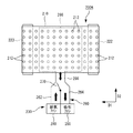
図8は、第2の実施の形態に係る搬送部200Bにおける搬送ベルト210の内側から上方を見た場合の構成の一例を示している。
[Configuration Example of
FIG. 8 shows an example of the configuration when the upper side is viewed from the inside of the
図8に示すように、搬送部200Bは、上述した搬送ベルト210、搬送ローラー220,222、エアー調整部230,330に加えて、風量調整部材290を備えている。
As illustrated in FIG. 8, the
風量調整部材290は、搬送ベルト210に形成された貫通孔212の開口率(エアーが通過する割合)を調整するための部材である。風量調整部材290は、用紙搬送方向D1に延びる帯状部材であって、行方向に並ぶ複数の貫通孔212のそれぞれの行間に対応した位置に設けられている。また、風量調整部材290は、図示しない駆動部に接続され、駆動部の駆動により用紙幅方向D2に所定範囲で移動可能となっている。所定範囲とは、例えば、貫通孔212の全体が開口する位置から貫通孔212の全体が閉塞する位置である。風量調整部材290の移動量は、貫通孔212から吹き出したいエアーの風量に応じて適宜設定される。
The air
なお、上述した例では、搬送経路Rの下方側から吹き出されるエアーに対する風量調整部材290について説明したが、搬送経路Rの上方側から吹き出されるエアーの風量調整についても風量調整部材290と同様の構成を採用することができる。具体的には、搬送経路Rの上方側のガイド部材150に、貫通孔152の開口率を調整する調整部材を設けることにより、エアー調整部330から吹き出されるエアーの風量を調整することができる。
In the above-described example, the air
[搬送部200Bの動作例]
図9は、第2の実施の形態に係るレジスト揺動補正時における用紙Pに付与されるエアーの状態を示す図である。なお、図9は、用紙搬送方向D1から上流側の搬送部200Bを見た場合の模式図である。また、図9の左側を画像形成装置100の奥側(以下、装置奥側と呼ぶ)とし、その右側を画像形成装置100の手前側(以下、装置手前側と呼ぶ)とする。
[Operation example of
FIG. 9 is a diagram illustrating a state of air applied to the paper P at the time of correcting the resist swing according to the second embodiment. FIG. 9 is a schematic diagram when the
制御部50は、用紙Pの曲がり補正後、片寄り検知センサ130により用紙Pの端部位置が検知されると、その検知結果に基づいて、用紙Pの用紙幅方向D2における揺動方向を取得する。具体的には、用紙幅方向D2の装置手前方向または装置奥側方向の情報を取得する。制御部50は、レジスト揺動補正時の揺動方向が装置奥側である場合、装置奥側に位置する、例えば図8の上側から3行目までの貫通孔212の略半分の面積を風量調整部材290を移動させて閉塞する。また、制御部50は、装置手前側に位置する、例えば図8の下側から4行目までの貫通孔212の全体が開くように風量調整部材290を制御する。
When the
これにより、図9に示すように、用紙Pの両面のそれぞれには、給気ファン240,340により、装置手前側では強い風量のエアーが吹き付けられ、装置奥側では弱い風量のエアーが吹き付けられ、用紙Pが一定の高さで浮上した状態で用紙搬送方向D1に沿って搬送される。
As a result, as shown in FIG. 9, a strong air volume is blown on the front side of the apparatus by the
また、レジスト揺動時の揺動方向が装置手前側である場合、上述した方法とは逆の制御によりエアーの風量を調整する。具体的には、装置手前側に位置する貫通孔212から吹き出されるエアーが弱い風量となるように風量調整部材290の動作を制御し、装置奥側に位置する貫通孔212から吹き出されるエアーが強い風量となるように風量調整部材290の動作を制御する。
Further, when the swinging direction at the time of swinging the resist is the front side of the apparatus, the air volume is adjusted by the control opposite to the above-described method. Specifically, the operation of the air
以上説明したように、第2の実施の形態によれば、レジスト揺動方向とは逆側におけるエアーの吹き出し風量を大きく設定するので、用紙Pの揺動をアシストすることができる。つまり、用紙Pの揺動方向とは反対側をエアーにより強く押すことで用紙Pを揺動方向に付勢することができる。これにより、確実かつ高精度なレジスト揺動補正を達成することができる。 As described above, according to the second embodiment, since the air blowing amount on the opposite side to the resist swinging direction is set large, the swinging of the paper P can be assisted. That is, the paper P can be biased in the swinging direction by strongly pressing the opposite side of the swinging direction of the paper P with air. Thereby, reliable and highly accurate resist swing correction can be achieved.
<第3の実施の形態>
第3の実施の形態では、レジスト揺動補正の揺動方向に合わせて給気ファン240等からのエアーの吹き出し方向を調整する点において、上述した第1および第2の実施の形態と相違している。なお、その他の画像形成装置100の構成や機能等は、上記第1の実施の形態で説明した画像形成装置100と同様であるため、共通の構成要素には同一の符号を付し、詳細な説明は省略する。
<Third Embodiment>
The third embodiment is different from the first and second embodiments described above in that the air blowing direction from the
[搬送部200Cの構成例]
図10は、第3の実施の形態に係る搬送部200Cの構成の一例を示している。なお、図10の左側を装置奥側と呼び、その右側を装置手前側と呼ぶ。図10に示すように、搬送部200Cは、上述した搬送ベルト210、搬送ローラー220,222、エアー調整部230,330に加えて、風向調整部材(ルーバー)292を備えている。
[Configuration Example of Transport Unit 200C]
FIG. 10 shows an example of the configuration of the transport unit 200C according to the third embodiment. The left side of FIG. 10 is referred to as the back side of the apparatus, and the right side thereof is referred to as the front side of the apparatus. As illustrated in FIG. 10, the
風向調整部材292は、搬送ベルト210の貫通孔212から吹き出されるエアーの風向を調整するための部材である。風向調整部材292は、用紙搬送方向D1に延びる帯状部材であって、行方向に並ぶ複数の貫通孔212のそれぞれの行間に対応した位置に設けられている。また、風向調整部材292は、図示しない駆動部に接続され、一方の長辺側を支点して回動可能に構成されている。
The air
[搬送部200Cの動作例]
次に、第3の実施の形態に係るレジスト揺動補正時における搬送部200Cの動作の一例を説明する。制御部50は、用紙Pの曲がり補正後、片寄り検知センサ130により用紙Pの端部位置が検知されると、その検知結果に基づいて用紙Pの用紙幅方向D2における片寄り量および揺動方向を算出する。制御部50は、図10に示すように、レジスト揺動補正時の揺動方向が装置奥側である場合、風向調整部材292の傾き方向が揺動方向に一致するように風向調整部材292を装置奥側に回転させる。つまり、搬送ベルト210の貫通孔212から吹き出されるエアーの風向が揺動方向となるように風向調整部材292を角度θに調整する。
[Example of operation of transport unit 200C]
Next, an example of the operation of the transport unit 200C at the time of resist swing correction according to the third embodiment will be described. When the
なお、搬送経路Rの上方側についても下方側と同様の方法により、エアー調整部330から吹き出される風量を調整することができる。
Note that the amount of air blown from the
以上説明したように、第3の実施の形態によれば、レジスト揺動方向とエアーの吹き出し方向とを一致させるので、用紙Pの揺動をアシストすることができる。つまり、揺動方向のエアーを用紙Pに吹き付けることで用紙Pを揺動方向に付勢することができる。これにより、確実かつ高精度なレジスト揺動補正を達成することができる。 As described above, according to the third embodiment, the resist rocking direction and the air blowing direction coincide with each other, so that the rocking of the paper P can be assisted. That is, by blowing air in the swing direction onto the paper P, the paper P can be urged in the swing direction. Thereby, reliable and highly accurate resist swing correction can be achieved.
<第4の実施の形態>
第4の実施の形態では、ファン240a等から吹き付けるエアーの風量を用紙幅方向D2において強弱を付ける点において、上述した第1〜第3の実施の形態と相違している。なお、その他の画像形成装置100の構成や機能等は、上記第1の実施の形態で説明した画像形成装置100と同様であるため、共通の構成要素には同一の符号を付し、詳細な説明は省略する。
<Fourth embodiment>
The fourth embodiment is different from the first to third embodiments described above in that the amount of air blown from the
[搬送部200Dの構成例]
図11は、第4の実施の形態に係る搬送部200Dの構成の一例を示している。なお、図11の左側を装置奥側と呼び、図11の右側を装置手前側と呼ぶ。図11に示すように、搬送部200Dは、上述した第1の実施の形態の構成に加え、エアー調整部230a,230b,330a,330bと、風向調整部材292とを備えている。
[Configuration Example of Transport Unit 200D]
FIG. 11 shows an example of the configuration of a transport unit 200D according to the fourth embodiment. The left side of FIG. 11 is referred to as the back side of the apparatus, and the right side of FIG. 11 is referred to as the front side of the apparatus. As shown in FIG. 11, the
エアー調整部230aは、用紙Pに対する搬送経路Rの下方側からのエアーの状態を調整するものであり、ファン240aとダクト260aとを有している。ファン240aは、風量の調整が可能なファンにより構成され、エアーをダクト260aに向けて吹き出す。ダクト260aは、一端部がファン240aに接続され、他端側が2本に分岐して搬送ベルト210の内側まで延在している。
The
エアー調整部230bは、用紙Pに対する搬送経路Rの下方側からのエアーの状態を調整するものであり、ファン240bとダクト260bとを有している。ファン240bは、風量の調整が可能なファンにより構成され、エアーをダクト260bに向けて吹き出す。ダクト260bは、一端部がファン240bに接続され、他端側が2本に分岐して搬送ベルト210の内側まで延在している。
The
ダクト260a,260bの分岐した他端部のそれぞれは、用紙幅方向D2において交互に配置されている。つまり、用紙幅方向D2の装置手前側から装置奥側に向かってダクト260b,260a,260b,260aの順に交互に配置されている。
The other branched ends of the
エアー調整部330aは、用紙Pに対する搬送経路Rの上方側からのエアーの状態を調整するものであり、ファン340aとダクト360aとを有している。ファン340aは、風量の調整が可能なファンにより構成され、エアーをダクト360aに向けて吹き出す。ダクト360aは、一端部がファン340aに接続され、他端側が2本に分岐してガイド部材150(図2参照)の上方に延在している。
The
エアー調整部330bは、用紙Pに対する搬送経路Rの上方側からのエアーの状態を調整するものであり、ファン340bとダクト360bとを有している。ファン340bは、風量の調整が可能なファンにより構成され、エアーをダクト360bに向けて吹き出す。ダクト360bは、一端部がファン340bに接続され、他端側が2本に分岐してガイド部材150の上方に延在している。
The
ダクト360a,360bの分岐した他端部のそれぞれは、用紙幅方向D2において交互に配置されている。つまり、用紙幅方向D2の装置手前側から装置奥側に向かってダクト360a,360b,360a,360bの順に交互に配置されている。
The other branched ends of the
なお、第4の実施の形態では、エアー調整部230a等において、エアーの吹き出しについてのみ説明しているが、例えば、第1の実施の形態で説明したように、エアーの吹き出し機構に加えて、エアーの吸引機構を設けることもできる。
In the fourth embodiment, only air blowing is described in the
[搬送部200Dの動作例]
次に、第4の実施の形態に係るレジスト揺動補正時における搬送部200Dの動作の一例を説明する。制御部50は、レジスト揺動補正時において、搬送経路Rの下方側のファン240aから吹き出すエアーの風量を第1の風量に設定し、ファン240bから吹き出すエアーの風量を第1の風量よりも多い第2の風量に設定する。これにより、図11に示したように、用紙幅方向D2に4分割された領域のうち、装置手前側から1、3番目の領域から吹き出されるエアーを強とし、2、4番目の領域から吹き出されるエアーを弱とすることができる。
[Operation example of transport unit 200D]
Next, an example of the operation of the transport unit 200D at the time of resist swing correction according to the fourth embodiment will be described. The
また、制御部50は、搬送経路Rの上方側のファン340aから吹き出すエアーの風量を第1の風量に設定し、ファン340bから吹き出すエアーの風量を第1の風量よりも多い第2の風量に設定する。これにより、図11に示したように、用紙幅方向D2に4分割された領域のうち、装置手前側から2,4番目の領域から吹き出されるエアーを強とし、1,3番目の領域から吹き出されるエアーを弱とすることができる。
In addition, the
また、用紙Pの表裏面における用紙幅方向D2の同位相となる領域においても、吹き付けられるエアーの風量に強弱を付けることができる。具体的には、装置手前側の1番目の同位相の領域では、下方側から吹き付けられるエアーの風量が強い第2の風量となり、上方側から吹き付けられるエアーの風量が弱い第1の風量となり、同位相においてもエアーの風量に強弱が付けられる。 Further, the air volume of the air to be blown can be increased or decreased even in the regions having the same phase in the paper width direction D2 on the front and back surfaces of the paper P. Specifically, in the first in-phase region on the front side of the apparatus, the air volume blown from the lower side becomes the second air volume that is strong, and the air volume blown from the upper side becomes the first air volume that is weak, Even in the same phase, the air volume is increased or decreased.
以上説明したように、第4の実施の形態によれば、用紙幅方向D2においてエアーの風量に強弱を付けるので、用紙Pは用紙幅方向D2において波打ち状態とすることができる。これにより、用紙Pを揺動方向に平行移動し易くなる。また、用紙Pの波状に湾曲した部分にエアーが当たり易くなるので、エアーによる揺動アシスト効果をより向上させることができる。 As described above, according to the fourth embodiment, the air volume is increased or decreased in the paper width direction D2, so that the paper P can be waved in the paper width direction D2. This facilitates parallel movement of the paper P in the swinging direction. Further, since air easily hits the waved portion of the paper P, the swing assist effect by the air can be further improved.
なお、本発明を実施の形態を用いて説明したが、本発明の技術的範囲は、上述した実施の形態に記載の範囲には限定されない。本発明の趣旨を逸脱しない範囲で、上述した実施の形態に、多様な変更または改良を加えることが可能である。例えば、上述した実施の形態では、給気ファン240および吸引ファン250を別々のファンにより構成しているが、1つのファンにより構成することもできる。また、図1に示す画像形成装置100はカラー画像を形成するものであるが、本発明はカラー画像を形成する画像形成装置に限らず、モノクロ画像を形成する画像形成装置にも適用することができる。
Although the present invention has been described using the embodiment, the technical scope of the present invention is not limited to the scope described in the embodiment. Various modifications or improvements can be added to the above-described embodiments without departing from the spirit of the present invention. For example, in the above-described embodiment, the
50 制御部
100 画像形成装置
120 レジストローラー対
200A,200B,200C,200D 搬送部
210 搬送ベルト
230,230a,230b 第1のエアー調整部
330,330a,330b 第2のエアー調整部
R 搬送経路
D1 用紙搬送方向
D2 用紙幅方向
50
Claims (11)
前記レジストローラー対よりも第1の方向の上流側に設けられ、用紙を前記レジストローラー対に搬送する搬送ベルトを有する搬送部と、
前記搬送ベルトにより搬送される用紙に対してエアーによる吸引または吹き出しを行う第1のエアー調整部と、
前記搬送ベルトにより用紙の搬送を行う場合に前記第1のエアー調整部を制御して用紙をエアーにより吸引する第1の動作と、前記レジストローラー対により用紙の揺動を行う場合に前記第1のエアー調整部を制御して用紙にエアーを吹き付ける第2の動作とを切り替える制御部と、
を備えることを特徴とする画像形成装置。 A pair of registration rollers that swings in a second direction perpendicular to the first direction of the paper transport direction while sandwiching the paper;
A transport unit provided upstream of the registration roller pair in the first direction and having a transport belt for transporting paper to the pair of registration rollers;
A first air adjusting unit that sucks or blows out air with respect to the paper transported by the transport belt;
When the sheet is conveyed by the conveying belt, the first air adjusting unit is controlled to suck the sheet by air, and when the sheet is swung by the registration roller pair, the first operation is performed. A control unit that controls a second operation of controlling the air adjusting unit of the second air and blowing air onto the paper;
An image forming apparatus comprising:
ことを特徴とする請求項1に記載の画像形成装置。 2. The image forming apparatus according to claim 1, further comprising a second air adjusting unit that is provided to face the first air adjusting unit across a sheet conveyance path and blows air to the sheet. .
ことを特徴とする請求項1または2に記載の画像形成装置。 The image forming apparatus according to claim 1, wherein the control unit rotates the conveyance belt in a first direction in the second operation.
ことを特徴とする請求項1から3の何れか一項に記載の画像形成装置。 2. The control unit according to claim 1, wherein, in the second operation, the air volume blown from at least one of the first and second air adjusting units is determined based on an input sheet condition. 4. The image forming apparatus according to any one of items 1 to 3.
ことを特徴とする請求項1から4の何れか一項に記載の画像形成装置。 The said control part adjusts the air volume balance of the air which blows off from the said 1st air adjustment part based on the moving direction in the 2nd direction of the said registration roller pair in a said 2nd operation | movement. Item 5. The image forming apparatus according to any one of Items 1 to 4.
ことを特徴とする請求項2から5の何れか一項に記載の画像形成装置。 The said control part adjusts the air volume balance of the air which blows off from the said 2nd air adjustment part based on the moving direction in the 2nd direction of the said registration roller pair in a said 2nd operation | movement. Item 6. The image forming apparatus according to any one of Items 2 to 5.
ことを特徴とする請求項1から6の何れか一項に記載の画像形成装置。 The said control part makes the movement direction in the 2nd direction of the said registration roller pair correspond with the blowing direction of the air from the said 1st air adjustment part in the said 2nd operation | movement. The image forming apparatus according to any one of 1 to 6.
ことを特徴とする請求項1から7の何れか一項に記載の画像形成装置。 The image forming according to any one of claims 1 to 7, wherein the control unit adjusts an air volume blown from the first air adjusting unit so as to be strong or weak in a second direction. apparatus.
ことを特徴とする請求項2から8の何れか一項に記載の画像形成装置。 The said control part makes the movement direction in the 2nd direction of the said registration roller pair correspond with the blowing direction of the air from the said 2nd air adjustment part in the said 2nd operation | movement. The image forming apparatus according to any one of 2 to 8.
ことを特徴とする請求項2から9の何れか一項に記載の画像形成装置。 The image formation according to any one of claims 2 to 9, wherein the control unit adjusts the air volume blown from the second air adjustment unit so as to increase or decrease in the second direction. apparatus.
ことを特徴とする請求項10に記載の画像形成装置。 The control unit adjusts the air volume blown from the first air adjusting unit and the air volume blown from the second air adjusting unit so as to be strong and weak in the same phase in the second direction. The image forming apparatus according to claim 10.
Priority Applications (2)
| Application Number | Priority Date | Filing Date | Title |
|---|---|---|---|
| JP2016085511A JP6705273B2 (en) | 2016-04-21 | 2016-04-21 | Image forming device |
| US15/492,224 US10392212B2 (en) | 2016-04-21 | 2017-04-20 | Image formation device |
Applications Claiming Priority (1)
| Application Number | Priority Date | Filing Date | Title |
|---|---|---|---|
| JP2016085511A JP6705273B2 (en) | 2016-04-21 | 2016-04-21 | Image forming device |
Publications (2)
| Publication Number | Publication Date |
|---|---|
| JP2017193423A true JP2017193423A (en) | 2017-10-26 |
| JP6705273B2 JP6705273B2 (en) | 2020-06-03 |
Family
ID=60090160
Family Applications (1)
| Application Number | Title | Priority Date | Filing Date |
|---|---|---|---|
| JP2016085511A Active JP6705273B2 (en) | 2016-04-21 | 2016-04-21 | Image forming device |
Country Status (2)
| Country | Link |
|---|---|
| US (1) | US10392212B2 (en) |
| JP (1) | JP6705273B2 (en) |
Citations (6)
| Publication number | Priority date | Publication date | Assignee | Title |
|---|---|---|---|---|
| JPS56140538U (en) * | 1980-03-21 | 1981-10-23 | ||
| JPH09175690A (en) * | 1995-11-30 | 1997-07-08 | Xerox Corp | Sheet advancing device |
| JP2000026001A (en) * | 1998-07-14 | 2000-01-25 | Sharp Corp | Sheet conveying device |
| JP2006151543A (en) * | 2004-11-26 | 2006-06-15 | Fuji Xerox Co Ltd | Sheet transport device and image forming apparatus |
| JP2011098790A (en) * | 2009-11-04 | 2011-05-19 | Canon Inc | Image forming device |
| US20120074639A1 (en) * | 2009-04-20 | 2012-03-29 | Konica Minolta Business Technologies, Inc. | Sheet feeding apparatus and image forming apparatus |
Family Cites Families (20)
| Publication number | Priority date | Publication date | Assignee | Title |
|---|---|---|---|---|
| JPH05124752A (en) | 1991-09-12 | 1993-05-21 | Fuji Xerox Co Ltd | Paper aligning unit for image forming device |
| JP3080828B2 (en) * | 1994-01-14 | 2000-08-28 | 京セラミタ株式会社 | Paper feeder |
| JP4035514B2 (en) * | 2004-04-28 | 2008-01-23 | キヤノン株式会社 | Skew correction device, sheet feeding device including the same, image forming device, and image reading device |
| JP2006206281A (en) * | 2005-01-31 | 2006-08-10 | Canon Inc | Image forming device |
| JP4890896B2 (en) * | 2006-03-15 | 2012-03-07 | キヤノン株式会社 | Image forming apparatus |
| JP2008065307A (en) * | 2006-08-11 | 2008-03-21 | Canon Inc | Image forming apparatus |
| JP5183351B2 (en) * | 2008-08-06 | 2013-04-17 | キヤノン株式会社 | Image forming apparatus |
| JP5338811B2 (en) * | 2008-09-16 | 2013-11-13 | コニカミノルタ株式会社 | Sheet supply apparatus and image forming system |
| JP2010269939A (en) * | 2009-04-20 | 2010-12-02 | Konica Minolta Business Technologies Inc | Sheet feeding apparatus and image forming apparatus |
| JP5494150B2 (en) * | 2009-12-10 | 2014-05-14 | コニカミノルタ株式会社 | Paper feeding device and image forming system |
| JP2013537872A (en) * | 2010-09-27 | 2013-10-07 | オセ−テクノロジーズ ビーブイ | Printing system having sheet conveying device |
| JP2012116610A (en) * | 2010-11-30 | 2012-06-21 | Ricoh Co Ltd | Sheet feeding device and image forming apparatus |
| JP5751821B2 (en) * | 2010-12-17 | 2015-07-22 | キヤノン株式会社 | Sheet feeding apparatus and image forming apparatus |
| US9581927B2 (en) * | 2011-02-10 | 2017-02-28 | Canon Kabushiki Kaisha | Image forming apparatus having detection of separation failure jams |
| CN103072832B (en) * | 2011-10-26 | 2016-02-17 | 夏普株式会社 | Paper feed and possess the image processing system of this paper feed |
| JP5799986B2 (en) * | 2013-07-17 | 2015-10-28 | コニカミノルタ株式会社 | Sheet supply apparatus and image forming apparatus |
| JP6347066B2 (en) * | 2013-07-24 | 2018-06-27 | コニカミノルタ株式会社 | Sheet supply apparatus and image forming apparatus |
| JP5932737B2 (en) * | 2013-08-30 | 2016-06-08 | 京セラドキュメントソリューションズ株式会社 | Inkjet recording device |
| JP6444060B2 (en) * | 2014-05-23 | 2018-12-26 | キヤノン株式会社 | Image forming apparatus |
| US9465359B2 (en) * | 2014-07-02 | 2016-10-11 | Sharp Kabushiki Kaisha | Air blowing system and image forming apparatus including same |
-
2016
- 2016-04-21 JP JP2016085511A patent/JP6705273B2/en active Active
-
2017
- 2017-04-20 US US15/492,224 patent/US10392212B2/en active Active
Patent Citations (6)
| Publication number | Priority date | Publication date | Assignee | Title |
|---|---|---|---|---|
| JPS56140538U (en) * | 1980-03-21 | 1981-10-23 | ||
| JPH09175690A (en) * | 1995-11-30 | 1997-07-08 | Xerox Corp | Sheet advancing device |
| JP2000026001A (en) * | 1998-07-14 | 2000-01-25 | Sharp Corp | Sheet conveying device |
| JP2006151543A (en) * | 2004-11-26 | 2006-06-15 | Fuji Xerox Co Ltd | Sheet transport device and image forming apparatus |
| US20120074639A1 (en) * | 2009-04-20 | 2012-03-29 | Konica Minolta Business Technologies, Inc. | Sheet feeding apparatus and image forming apparatus |
| JP2011098790A (en) * | 2009-11-04 | 2011-05-19 | Canon Inc | Image forming device |
Also Published As
| Publication number | Publication date |
|---|---|
| US20170308022A1 (en) | 2017-10-26 |
| US10392212B2 (en) | 2019-08-27 |
| JP6705273B2 (en) | 2020-06-03 |
Similar Documents
| Publication | Publication Date | Title |
|---|---|---|
| JP4810407B2 (en) | Sheet feeding apparatus and image forming apparatus | |
| JP6314948B2 (en) | Image forming apparatus | |
| JP2016044067A (en) | Carrier device and image forming device | |
| US20190129346A1 (en) | Image former and conveyance control method | |
| JP4348978B2 (en) | Image forming apparatus and control method thereof | |
| JP6217692B2 (en) | Image forming apparatus | |
| JP2003146485A (en) | Sheet feeder and image forming device | |
| JP2014038241A (en) | Image forming apparatus | |
| US20190129345A1 (en) | Image forming apparatus and conveyance control method | |
| JP2017105625A (en) | Image formation device | |
| JP7024325B2 (en) | Image forming device and transfer control method | |
| JP6705273B2 (en) | Image forming device | |
| JP2019048679A (en) | Sheet conveying device and image forming device | |
| JP2018025615A (en) | Image formation device | |
| JP2009271469A (en) | Image forming apparatus | |
| JP4011903B2 (en) | Image forming apparatus | |
| JP4336258B2 (en) | Paper reversing and conveying apparatus and image forming apparatus having the same | |
| JP6601252B2 (en) | Image forming apparatus | |
| JP2018040987A (en) | Image forming apparatus | |
| JP2006273470A (en) | Curl correcting device and image forming apparatus | |
| JP2023112977A (en) | Image forming apparatus | |
| JP2002316748A (en) | Paper feeder and image forming device | |
| JP2005351302A (en) | Belt apparatus | |
| JP2020090345A (en) | Image forming apparatus and conveyance control method | |
| JP2023020342A (en) | Sheet conveying device and image forming device |
Legal Events
| Date | Code | Title | Description |
|---|---|---|---|
| A621 | Written request for application examination |
Free format text: JAPANESE INTERMEDIATE CODE: A621 Effective date: 20190214 |
|
| A977 | Report on retrieval |
Free format text: JAPANESE INTERMEDIATE CODE: A971007 Effective date: 20191205 |
|
| A131 | Notification of reasons for refusal |
Free format text: JAPANESE INTERMEDIATE CODE: A131 Effective date: 20191224 |
|
| A521 | Request for written amendment filed |
Free format text: JAPANESE INTERMEDIATE CODE: A523 Effective date: 20200213 |
|
| TRDD | Decision of grant or rejection written | ||
| A01 | Written decision to grant a patent or to grant a registration (utility model) |
Free format text: JAPANESE INTERMEDIATE CODE: A01 Effective date: 20200414 |
|
| A61 | First payment of annual fees (during grant procedure) |
Free format text: JAPANESE INTERMEDIATE CODE: A61 Effective date: 20200427 |
|
| R150 | Certificate of patent or registration of utility model |
Ref document number: 6705273 Country of ref document: JP Free format text: JAPANESE INTERMEDIATE CODE: R150 |