JP2017193370A - LNG transfer monitoring system - Google Patents
LNG transfer monitoring system Download PDFInfo
- Publication number
- JP2017193370A JP2017193370A JP2016086410A JP2016086410A JP2017193370A JP 2017193370 A JP2017193370 A JP 2017193370A JP 2016086410 A JP2016086410 A JP 2016086410A JP 2016086410 A JP2016086410 A JP 2016086410A JP 2017193370 A JP2017193370 A JP 2017193370A
- Authority
- JP
- Japan
- Prior art keywords
- transfer
- lng
- worker
- information
- tank
- Prior art date
- Legal status (The legal status is an assumption and is not a legal conclusion. Google has not performed a legal analysis and makes no representation as to the accuracy of the status listed.)
- Pending
Links
Images

Landscapes
- Loading And Unloading Of Fuel Tanks Or Ships (AREA)
- Filling Or Discharging Of Gas Storage Vessels (AREA)
Abstract
【課題】LNGの移送にかかるサテライト設備管理者の作業負担を軽減する。【解決手段】LNGを収容したタンクローリー(車両)12からLNGタンク16へのLNGの移送を監視するLNG移送監視システム100は、タンクローリー(車両)12からLNGタンク16へのLNGの移送に関する移送情報112を取得する移送情報取得装置110と、移送が行われる位置から離隔した監視装置130と、移送情報112をネットワーク経由で監視装置130に送信する送信装置120と、を備える。【選択図】図1An object of the present invention is to reduce the workload of a satellite facility manager involved in the transfer of LNG. A LNG transfer monitoring system (100) for monitoring transfer of LNG from a tank truck (vehicle) containing LNG to an LNG tank (16) includes transfer information (112) regarding transfer of LNG from the tank truck (vehicle) (12) to an LNG tank (16). , a monitoring device 130 separated from the position where the transfer is performed, and a transmitting device 120 transmitting the transfer information 112 to the monitoring device 130 via a network. [Selection drawing] Fig. 1
Description
本発明は、LNG(liquefied natural gas:液化天然ガス)を収容した車両からLNGタンクへのLNGの移送を監視するLNG移送監視システムに関する。 The present invention relates to an LNG transfer monitoring system that monitors the transfer of LNG from a vehicle containing LNG (liquefied natural gas) to an LNG tank.
LNGを収容したタンクローリーなどの車両から、サテライトに設置されたLNGタンクへLNGを移送する際、従来は、サテライトの設備管理者と、LNGを運搬した作業者とが共同して移送作業を実行していた。具体的には、LNGを運搬した作業者が実質的なLNGの移送作業を行い、サテライトの設備管理者は、作業者によるLNGの移送作業が適切に行われているかを監視する(例えば、特許文献1)。 When transporting LNG from a vehicle such as a tank lorry that contains LNG to an LNG tank installed in the satellite, conventionally, the facility manager of the satellite and the operator who transported the LNG have jointly performed the transfer work. It was. Specifically, the worker who transported the LNG performs a substantial LNG transfer operation, and the satellite facility manager monitors whether the LNG transfer operation by the worker is properly performed (for example, patents). Reference 1).
ところで、LNGを収容した車両からLNGタンクへのLNGの移送作業は、例えば1時間といったように長時間を費やす場合がある。そのため、移送作業が行われている間は、作業者のみならず、サテライトの設備管理者も移送作業の監視や作業者の補助のために移送現場に拘束され、その負担が大きくなっていた。 By the way, there is a case where the LNG transfer work from the vehicle containing LNG to the LNG tank takes a long time such as 1 hour. Therefore, while the transfer work is being performed, not only the workers but also the facility managers of the satellites are restrained at the transfer site for monitoring the transfer work and assisting the worker, and the burden is increased.
本発明は、このような課題に鑑み、LNGの移送作業にかかるサテライト設備管理者の作業負担を軽減することができるLNG移送監視システムを提供することを目的とする。 In view of such a problem, an object of the present invention is to provide an LNG transfer monitoring system capable of reducing the work burden on a satellite facility administrator involved in an LNG transfer operation.
上記課題を解決するために、本発明のLNG移送監視システムは、LNGを収容した車両からLNGタンクへのLNGの移送を監視するLNG移送監視システムであって、車両からLNGタンクへのLNGの移送に関する移送情報を取得する移送情報取得装置と、移送が行われる位置から離隔した監視装置と、移送情報をネットワーク経由で監視装置に送信する送信装置と、を備えたことを特徴とする。 In order to solve the above-mentioned problems, an LNG transfer monitoring system according to the present invention is an LNG transfer monitoring system for monitoring the transfer of LNG from a vehicle containing LNG to an LNG tank, and transferring LNG from the vehicle to the LNG tank. The transfer information acquisition apparatus which acquires the transfer information regarding, the monitoring apparatus separated from the position where the transfer is performed, and the transmission apparatus which transmits the transfer information to the monitoring apparatus via the network are provided.
また、監視装置は、移送情報を逐次表示する表示部と、移送情報が所定の条件を満たしたか否かを判定する条件判定部と、移送情報が所定の条件を満たすと、所定の警告報知を行う警告報知部と、を備えるとよい。 In addition, the monitoring device includes a display unit that sequentially displays the transfer information, a condition determination unit that determines whether or not the transfer information satisfies a predetermined condition, and a predetermined warning notification when the transfer information satisfies the predetermined condition. It is good to provide the warning alerting part to perform.
また、移送情報は、移送を行う作業者が作業できない状態にあるか否かに関する情報を含み、所定の条件は、作業者が作業できない状態が所定時間以上継続していることを含むとよい。 In addition, the transfer information includes information regarding whether or not the worker who performs the transfer is in a state where the worker cannot work, and the predetermined condition may include that the state where the worker cannot work continues for a predetermined time or more.
また、作業者が作業できない状態は、作業者が転倒している状態を含むとよい。 In addition, the state in which the worker cannot work may include a state in which the worker is falling.
本発明によれば、LNGの移送作業にかかるサテライト設備管理者の作業負担を軽減することができる。 ADVANTAGE OF THE INVENTION According to this invention, the work burden of the satellite facility manager concerning the transfer operation | work of LNG can be reduced.
以下に添付図面を参照しながら、本発明の好適な実施形態について詳細に説明する。かかる実施形態に示す寸法、材料、その他具体的な数値等は、発明の理解を容易とするための例示にすぎず、特に断る場合を除き、本発明を限定するものではない。なお、本明細書および図面において、実質的に同一の機能、構成を有する要素については、同一の符号を付することにより重複説明を省略し、また本発明に直接関係のない要素は図示を省略する。 Hereinafter, preferred embodiments of the present invention will be described in detail with reference to the accompanying drawings. The dimensions, materials, and other specific numerical values shown in the embodiments are merely examples for facilitating the understanding of the invention, and do not limit the present invention unless otherwise specified. In the present specification and drawings, elements having substantially the same function and configuration are denoted by the same reference numerals, and redundant description is omitted, and elements not directly related to the present invention are not illustrated. To do.
(LNG移送監視システム100)
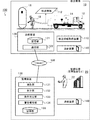
図1は、LNG移送監視システム100の概要を示す説明図である。LNG移送監視システム100は、図1に示すように、LNGの移送作業が行われる移送現場10と、移送現場10から離隔した監視位置20とをネットワーク接続し、移送現場10でのLNGの移送作業を監視位置20(例えば、サテライト設備のある敷地内の管理施設)から遠隔で監視することを可能にする。
(LNG transfer monitoring system 100)
FIG. 1 is an explanatory diagram showing an outline of the LNG
なお、本実施形態では、移送現場10におけるタンクローリー12(ローリー14)からLNGタンク16へのLNGの移送作業は、サテライトの設備管理者22の管理のもと、タンクローリー12(ローリー14)の搬送者18が行う。また、従来、LNGの移送作業を搬送者18と共同で行っていたサテライトの設備管理者22は、移送現場10から離隔した監視位置20で待機する。
In the present embodiment, the LNG transfer work from the tank lorry 12 (the lorry 14) to the
サテライトの設備管理者22は、監視位置20において、移送現場10における搬送者18によるLNGの移送作業を遠隔で監視し、並行して他の作業を行う場合もある。なお、以下の説明では、タンクローリー12(ローリー14)の搬送者18を、LNGの移送作業を行う作業者18と称し、サテライトの設備管理者22を単に管理者22と称する。
The
LNG移送監視システム100は、図1に示すように、移送情報取得装置110と、送信装置120と、監視装置130と、連絡装置140とを含んで構成される。
As shown in FIG. 1, the LNG
移送情報取得装置110は、LNGの移送現場10に配置され、LNGの移送に関する移送情報112を取得する。ここで取得される移送情報112には、例えばLNGの移送中におけるLNGタンク16内の圧力や、LNGタンク16内のLNGの容量などの情報が含まれる。なお、移送情報112の詳細については後述する。
The transfer
送信装置120は、LNGの移送現場10に配置され、記憶部121と、通信部122とを含んで構成される。記憶部121は、移送情報取得装置110で取得した移送情報112を記憶する。通信部122は、移送情報112の送信先である監視装置130との通信を制御し、記憶部121に記憶した移送情報112をネットワークNW経由で監視装置130へ送信する。
The
監視装置130は、監視位置20に配置され、通信部131と、表示部132と、条件判定部133と、警告報知部134とを含んで構成される。通信部131は、送信装置120との通信を制御し、送信装置120から移送情報112を受信する。表示部132は、通信部131で受信した移送情報112を逐次表示する。条件判定部133は、移送情報112があらかじめ設定された所定の条件を満たすか否かを判定する。警告報知部134は、移送情報112が所定の条件を満たすと判定された場合に、所定の警告報知を行う。記憶部135は、通信部131で受信した移送情報112を記憶する。なお、所定の条件は、移送作業に何らかの異常が生じた旨の警告報知を行うか否かを判定するための条件である。この所定の条件の詳しい内容については後述する。
The
連絡装置140は、移送現場10および監視位置20の双方に配置され、例えば携帯電話やスマートフォン、トランシーバなどで構成される。連絡装置140は、例えば移送作業中に何らかの異常が発生した場合に、管理者22が作業者18に具体的な対処方法を音声で指示するような場合に使用される。
The
(LNG移送作業の概要)
次に、実際のLNG移送作業の概要について、図2に基づき説明する。
(Outline of LNG transfer work)
Next, an outline of actual LNG transfer work will be described with reference to FIG.
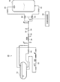
図2は、LNGが収容されたローリー14からLNGタンク16へLNGを移送するための移送ライン30の概略を示す説明図である。LNGが収容されたローリー14からLNGタンク16へLNGを移送するに際し、まず、作業者18は、ローリー側充填口32とタンク側充填口34とを、LNG移送用のフレキシブルホース36で接続し、移送ライン30を確立する。
FIG. 2 is an explanatory diagram showing an outline of a
次に、作業者18は、移送ライン30に漏洩のないことを確認した後、ローリー側充填弁38等を操作してローリー14内のLNGを少量、フレキシブルホース36内へ導入し、フレキシブルホース36内のガス置換を行う。ガス置換は概ね30秒間実施する。
Next, after confirming that there is no leakage in the
次に、作業者18は、ローリー加圧ライン42に設置された弁を操作して、ローリー14内の圧力を所定圧力(例えば、0.6MPa)まで昇圧する。そして、ローリー14内の圧力がLNGタンク16内の圧力と同圧近くになったら、ローリー側払出し弁40等を操作し、LNGタンク16の上部に接続される上部受入ライン44、およびLNGタンク16の下部に接続される下部受入ライン46のクールダウン(冷却)を行う。なお、ローリー側充填弁38は、常時開弁状態に保たれており、クールダウン(冷却)を含む移送作業中に何らかの異常が発生した場合などの緊急時に遮断(閉弁)される。
Next, the
上部受入ライン44および下部受入ライン46のクールダウン(冷却)が完了したら、作業者18は、ローリー側払出し弁40等を操作するとともに、LNGタンク16側の上部受入ライン44に設けられた上部充填弁48、および、下部受入ライン46に設けられた下部充填弁50を開弁し、ローリー14内とLNGタンク16内との差圧により、ローリー14内からLNGタンク16内へLNGを移送(充填)する。このとき、LNGタンク16側では、タンク内の圧力が所定の圧力範囲(例えば、0.28MPa〜0.4MPa)を維持し、かつ、LNGタンク16内のLNGの容量がタンクの総貯槽量の90%以上とならないように、LNGの移送状態を管理する。
When the cooling down (cooling) of the
ここで、LNGタンク16内の圧力の調整は、LNGタンク16内の圧力を測定する圧力センサの出力値に基づき、上部充填弁48および下部充填弁50を操作することで行われる。具体的には、上部充填弁48を開弁方向に操作するとLNGタンク16内の圧力が下降し、下部充填弁50を開弁方向に操作するとLNGタンク16内の圧力が上昇する。
Here, the pressure in the
この上部充填弁48および下部充填弁50の操作は、従来は管理者22が行い、LNGタンク16内の圧力を所定の圧力範囲に維持していた。一方、本実施形態では、管理者22が行っていたこれら2つの充填弁の操作を作業者18に委託し、作業者18が上部充填弁48および下部充填弁50を操作して、LNGタンク16内の圧力を所定の圧力範囲に維持する。一方、管理者22は、従来行っていた上部充填弁48および下部充填弁50の操作を行うことなく、監視位置20において、LNGタンク16内の圧力を中心とする後述の移送情報112の管理に集中する。なお、図2に示すように、LNGタンク16内の圧力に応じて上部充填弁48および下部充填弁50の開度を自動制御する自動制御装置60を設け、LNGタンク16内の圧力が所定の圧力範囲内で一定となるように、これら2つの充填弁の開度を自動制御するようにしてもよい。
The operation of the
以上の手順により、LNGタンク16内の圧力を所定の圧力範囲内に維持しつつ、ローリー14内のLNGの移送(充填)が完了したら、ローリー側払出し弁40、上部充填弁48および下部充填弁50を閉弁し、フレキシブルホース36を外してLNGの移送(充填)作業を完了する。
When the transfer (filling) of the LNG in the
次に、移送情報取得装置110が取得する移送情報112に含まれる具体的な情報の概要、および各情報について警告報知を行う条件について、図3に基づき説明する。
Next, an outline of specific information included in the
(1)LNGタンク内の圧力
移送情報取得装置110は、自動制御装置60を通じて、LNG移送中におけるLNGタンク16内の圧力(貯槽圧力)を取得する。LNGタンク16内の圧力は、前述のように、作業者18が上部充填弁48および下部充填弁50を手動で操作するか、もしくは自動制御装置60がこれらの充填弁の開度を自動制御することにより、所定の圧力範囲内に維持される。なお、移送情報取得装置110は、作業者18の操作入力を通じてLNGタンク16内の圧力を取得してもよい。
(1) Pressure in LNG tank The transfer
そして、条件判定部133は、LNGタンク16内の圧力と、所定の圧力範囲(例えば0.28MPa〜0.4MPa)とを比較し、LNGタンク16内の圧力が所定の圧力範囲を外れた場合に、LNGタンク16内の圧力に異常が生じたと判定する。条件判定部133により、LNGタンク16内の圧力に異常が生じたと判定されると、警告報知部134は、LNGタンク16内の圧力異常を知らせる旨の警告報知を行う。
Then, the
(2)作業者が作業できない状態にあるか否か
移送情報取得装置110は、移送作業を行う作業者18が作業できない状態にあるか否かに関する情報を取得する。ここで、作業者18が作業できない状態とは、作業者18の健全性に何らかの異常が生じて作業者18が移送作業を実施できなくなった状態をいい、例えば、作業者18がガスを吸引して転倒した場合や、急な体調不良により作業を行えない状態に陥った場合などが含まれる。
(2) Whether the worker is in a state where the worker cannot work The transfer
具体的に、移送情報取得装置110は、作業者18が作業できない状態にあるか否かを、作業者18の定期的な操作入力を通じて確認し、作業者18からの操作入力が確認できている間は、作業できない状態にないと判断する。一方、移送情報取得装置110は、作業者18からの操作入力が所定時間途切れた場合、作業者18が作業できない状態(例えば、転倒している状態)にあると判断する。
Specifically, the transfer
そして、条件判定部133は、作業者18が作業できない状態が所定時間(例えば、3分)以上継続している場合に、作業者18の健全性に異常が生じたと判定する。条件判定部133により、作業者18の健全性に異常が生じたと判定されると、警告報知部134は、作業者18の健全性異常を知らせる旨の警告報知を行う。
Then, the
(3)作業者からの定期報告
移送情報取得装置110は、作業者18からの定期報告を取得する。具体的な報告の内容は、作業者18が健全であること、作業状況が正常であること、移送情報取得装置110および送信装置120が正常に機能していること等、とする。移送情報取得装置110は、作業者18の定期的な操作入力を通じて、作業者18からの定期報告を取得する。
(3) Regular Report from Worker The transfer
そして、条件判定部133は、作業者18からの定期報告が所定時間(例えば、10分)以上なされていない場合に、作業者18の健全性や作業状況、移送情報取得装置110等の機器に異常が生じたと判定する。条件判定部133により、作業者18の健全性や作業状況、移送情報取得装置110等の機器に異常が生じたと判定されると、警告報知部134は、当該異常を知らせる旨の警告報知を行う。
Then, the
(4)LNGタンク内のLNG容量
移送情報取得装置110は、LNGタンク16に設けられた液面計を通じて、LNG移送中におけるLNGタンク16内のLNG容量を取得する。なお、移送情報取得装置110は、作業者18によるLNG容量の操作入力を通じて、LNGタンク16内のLNG容量を取得してもよい。
(4) LNG capacity in LNG tank The transfer
そして、条件判定部133は、LNG容量(移送開始時におけるLNG量と現時点までの移送量との和)が、LNGタンク16の総貯槽量の85%以上となっている場合に、LNG容量の異常と判定する。また、条件判定部133は、LNG容量の増加率からLNGの移送速度を算出し、当該移送速度が所定の速度範囲を外れた場合に、LNGの移送に異常が生じたと判定してもよい。条件判定部133により、LNG容量もしくはLNGの移送に異常が生じたと判定されると、警告報知部134は、これらの異常を知らせる旨の警告報知を行う。
The
(5)充填弁の操作情報
移送情報取得装置110は、自動制御装置60を通じて、LNGの移送開始後(いわゆる移送安定期)における上部充填弁48および下部充填弁50の操作に関する情報を取得する。上部充填弁48および下部充填弁50の操作に関する情報には、例えば上部充填弁48および下部充填弁50の開度や、これら各充填弁が操作されたことを示す検出信号などが含まれる。
(5) Filling Valve Operation Information The transfer
そして、条件判定部133は、LNGの移送開始後における上部充填弁48および下部充填弁50の開度変化が、所定時間(例えば、5分)以内に所定回数以上確認された場合に、充填弁の操作に異常が生じたと判定する。条件判定部133により、充填弁の操作に異常が生じたと判定されると、警告報知部134は、充填弁の操作異常を知らせる旨の警告報知を行う。なお、充填弁の操作異常は、主にLNGタンク16内の圧力を測定する圧力センサの故障により、その出力値(圧力)が安定しない場合に発生することが想定される。
Then, the
(6)移送現場の映像情報
移送情報取得装置110は、撮像方向を変更可能に設置されたビデオカメラを通じて、移送現場10の映像情報を取得する。なお、移送現場10の映像情報は、必ずしも移送情報取得装置110で取得される必要はなく、管理者22が移送現場10の映像情報を確認したい場合にのみ取得されればよい。
(6) Video Information on Transfer Site The transfer
そして、条件判定部133は、移送現場10の映像情報について、フレーム毎の差分を抽出し、抽出した差分に基づいて異常発生の有無を判定する。例えば、フレーム毎の差分が急激に大きくなったら、移送現場10で何らかの事故が発生したと判定し、フレーム毎の差分が抽出されない状態が所定時間以上続いたら、作業者18が転倒したか、あるいは作業者18が移送現場10からいなくなった、と判定する。条件判定部133により、上記の異常が生じたと判定されると、警告報知部134は、当該異常を知らせる旨の警告報知を行う。
And the
(7)ガス漏れ発生の有無
移送情報取得装置110は、移送現場10に設置されたガス漏れ警報器を通じて、移送現場10でのガス漏れ発生の有無に関する情報を取得する。なお、移送情報取得装置110は、作業者18の操作入力を通じて、移送現場10でのガス漏れ発生の有無に関する情報を取得してもよい。
(7) Presence / absence of occurrence of gas leak The transfer
そして、条件判定部133は、ガス漏れが発生したことを示す情報を確認した場合に、移送現場10でガス漏れが発生したと判定する。条件判定部133により、移送現場10でガス漏れが発生したと判定されると、警告報知部134は、移送現場10でのガス漏れの発生を知らせる旨の警告報知を行う。
And the
(8)その他
移送情報取得装置110は、移送現場10の天候、地震発生の有無、機械異常やガス漏れに起因する異音の有無などに関する情報を取得する。また、移送情報取得装置110は、移送ライン30への霜付状況や、移送ライン30周辺のガスの微少漏洩の有無に関する情報も併せて取得する。
(8) Others The transfer
そして、条件判定部133は、これらに関する情報のいずれかに異常を示す情報が含まれている場合に、異常(例えば天候異常)と判定する。条件判定部133により、これらの情報のいずれかに異常が認められると判定されると、警告報知部134は、当該異常の発生を知らせる旨の警告報知を行う。
And the
以上のように、LNG移送監視システム100では、移送情報取得装置110が上記(1)〜(8)の情報を含んで構成される移送情報112を取得する。そして、送信装置120は、移送情報取得装置110で取得した移送情報112を、ネットワーク経由で監視装置130へ送信する。監視装置130では、送信装置120から受信した移送情報112を記憶部135に記憶するとともに、表示部132に逐次表示する。
As described above, in the LNG
また、条件判定部133は、移送情報112に含まれる(1)〜(8)の情報が、それぞれに対応する警告報知の条件を満たすか否かを判定する。そして、条件判定部133により、いずれかの情報が警告報知の条件を満たしていると判定された場合、警告報知部134が、アラームや警告音等の所定の方法により、管理者22に対して警告報知を行う。
Moreover, the
管理者22は、警告報知部134が発する警告報知に基づき、速やかに移送現場10の状況を確認し、連絡装置140を用いて現場の作業者18に遠隔で対応指示を送る。また、現場の作業者18のみでは対応が困難である場合には、管理者22が対応を引き継ぎ、自動制御装置60を介して上部充填弁48および下部充填弁50を遠隔で操作したり、あるいは移送現場10へ赴いて対応する。
The
このように、LNG移送監視システム100によれば、管理者22は、LNGの移送状況を、移送現場10から離隔した位置で把握することができる。具体的には、管理者22は、移送現場10から離隔した監視位置20において、監視装置130の表示部132を通じて、移送作業が警告報知に至りそうな状況にないことを適宜確認しつつ、警告報知部134から何らかの警告報知がなされた場合や、作業者18からの連絡装置140への連絡があった場合に、それらに対応する。
Thus, according to the LNG
これにより、管理者22は、移送現場10での作業(上部充填弁48および下部充填弁50の操作等)と、それに伴う移送現場10への長時間の拘束が不要となり、その作業負担が従来に比して軽減されるとともに、移送情報112の取得や管理をはじめとする移送作業の監視業務に集中することができ、移送作業の安全性を高めることができる。
As a result, the
以上、添付図面を参照しながら本発明の好適な実施形態について説明したが、本発明はかかる実施形態に限定されないことは言うまでもない。当業者であれば、特許請求の範囲に記載された範疇内において、各種の変更例または修正例に想到し得ることは明らかであり、それらについても当然に本発明の技術的範囲に属するものと了解される。 As mentioned above, although preferred embodiment of this invention was described referring an accompanying drawing, it cannot be overemphasized that this invention is not limited to this embodiment. It will be apparent to those skilled in the art that various changes and modifications can be made within the scope of the claims, and these are naturally within the technical scope of the present invention. Understood.
例えば、上記実施形態では、移送情報112を取得する移送情報取得装置110と、取得した移送情報112を監視装置130へ送信する送信装置120とを、別の装置で構成した例を説明したが、移送情報取得装置110にデータの送信機能を付加し、移送情報取得装置110が自ら監視装置130へ移送情報112を送信するようにしてもよい。
For example, in the above-described embodiment, an example in which the transfer
また、移送情報112に含まれる情報として図3に示した(1)〜(8)の情報は、あくまでも例示であり、移送情報112としてこのうちいずれかの情報のみを採用してもよいし、これらの他に必要となる情報を追加してもよい。また、(1)〜(8)の情報のうち、いくつかの情報を組み合わせて、所定の条件と比較するようにしてもよい。
Further, the information of (1) to (8) shown in FIG. 3 as information included in the
また、移送情報112が所定の条件を満たした場合の警告報知部134による警告報知の態様としては、上記したアラームや警告音に限らず、管理者22が異常を認識することができる態様であればどのようなものでも構わない。
In addition, the warning notification mode by the
また、作業者18が移送情報112を監視装置130へ送信する頻度は、例えば3分間隔とするなど、あらかじめ作業者18と管理者22との話し合いの上で取り決めておけばよい。ただし、移送情報112は、移送作業中に何らかの異常が発生した場合に、少なくとも管理者22が直ちに状況を把握できるような頻度で監視装置130へ送信されることが望ましい。
Further, the frequency at which the
本発明は、LNGを収容した車両からLNGタンクへのLNGの移送を監視するLNG移送監視システムに利用することができる。 INDUSTRIAL APPLICABILITY The present invention can be used for an LNG transfer monitoring system that monitors the transfer of LNG from a vehicle containing LNG to an LNG tank.
12 タンクローリー(車両)
16 LNGタンク
100 LNG移送監視システム
110 移送情報取得装置
112 移送情報
120 送信装置
130 監視装置
131 通信部
132 表示部
133 条件判定部
134 警告報知部
12 Tanker (vehicle)
16
Claims (4)
前記車両から前記LNGタンクへの前記LNGの移送に関する移送情報を取得する移送情報取得装置と、
前記移送が行われる位置から離隔した監視装置と、
前記移送情報をネットワーク経由で前記監視装置に送信する送信装置と、
を備えることを特徴とするLNG移送監視システム。 An LNG transfer monitoring system for monitoring the transfer of LNG from a vehicle containing LNG to an LNG tank,
A transfer information acquisition device for acquiring transfer information related to the transfer of the LNG from the vehicle to the LNG tank;
A monitoring device spaced from a position where the transfer is performed;
A transmission device for transmitting the transport information to the monitoring device via a network;
An LNG transfer monitoring system comprising:
前記移送情報を逐次表示する表示部と、
前記移送情報が所定の条件を満たしたか否かを判定する条件判定部と、
前記移送情報が前記所定の条件を満たすと、所定の警告報知を行う警告報知部と、
を備えることを特徴とする請求項1に記載のLNG移送監視システム。 The monitoring device
A display unit for sequentially displaying the transfer information;
A condition determination unit for determining whether or not the transfer information satisfies a predetermined condition;
When the transfer information satisfies the predetermined condition, a warning notification unit that performs a predetermined warning notification;
The LNG transfer monitoring system according to claim 1, comprising:
前記所定の条件は、前記作業者が作業できない状態が所定時間以上継続していることを含むことを特徴とする請求項2に記載のLNG移送監視システム。 The transfer information includes information on whether or not the worker who performs the transfer is in a state where it cannot work,
The LNG transfer monitoring system according to claim 2, wherein the predetermined condition includes a state in which the worker cannot work for a predetermined time or longer.
Priority Applications (1)
| Application Number | Priority Date | Filing Date | Title |
|---|---|---|---|
| JP2016086410A JP2017193370A (en) | 2016-04-22 | 2016-04-22 | LNG transfer monitoring system |
Applications Claiming Priority (1)
| Application Number | Priority Date | Filing Date | Title |
|---|---|---|---|
| JP2016086410A JP2017193370A (en) | 2016-04-22 | 2016-04-22 | LNG transfer monitoring system |
Publications (1)
| Publication Number | Publication Date |
|---|---|
| JP2017193370A true JP2017193370A (en) | 2017-10-26 |
Family
ID=60154492
Family Applications (1)
| Application Number | Title | Priority Date | Filing Date |
|---|---|---|---|
| JP2016086410A Pending JP2017193370A (en) | 2016-04-22 | 2016-04-22 | LNG transfer monitoring system |
Country Status (1)
| Country | Link |
|---|---|
| JP (1) | JP2017193370A (en) |
Citations (14)
| Publication number | Priority date | Publication date | Assignee | Title |
|---|---|---|---|---|
| JP2001295994A (en) * | 2000-04-11 | 2001-10-26 | Air Liquide Japan Ltd | Compressed gas transfer and filling method |
| JP2001301898A (en) * | 2000-04-21 | 2001-10-31 | Tatsuno Corp | Unloading management equipment for gas stations |
| JP2001357106A (en) * | 2000-04-14 | 2001-12-26 | Nippon Sanso Corp | Gas delivery system and method, and gas container management method |
| JP2002037400A (en) * | 2000-07-31 | 2002-02-06 | Tatsuno Corp | Filling station lubrication management system |
| JP2004018097A (en) * | 2002-06-20 | 2004-01-22 | Showa Kiki Kogyo Co Ltd | Unloading system by tanker |
| JP2005075561A (en) * | 2003-09-01 | 2005-03-24 | Chugoku Electric Power Co Inc:The | Method and system for control of lng bulk container |
| JP2005200099A (en) * | 2003-12-16 | 2005-07-28 | Showa Kiki Kogyo Co Ltd | Level gauge and liquid volume transfer system |
| JP2006172431A (en) * | 2004-11-22 | 2006-06-29 | Asahi Breweries Ltd | Abnormal alarm device |
| JP2007310855A (en) * | 2006-04-17 | 2007-11-29 | Fujitsu Ltd | Quality assurance system and quality assurance method |
| JP2008190847A (en) * | 2007-02-06 | 2008-08-21 | Samsung Electronics Co Ltd | Air conditioner and electric valve control method thereof |
| JP2008217368A (en) * | 2007-03-02 | 2008-09-18 | Asahi Breweries Ltd | Alarm system |
| JP2009159239A (en) * | 2007-12-26 | 2009-07-16 | Nippon Steel Corp | Anomaly detection support system |
| JP2012251606A (en) * | 2011-06-03 | 2012-12-20 | Taiyo Nippon Sanso Corp | Liquefied hydrogen storage supply equipment |
| JP2015078719A (en) * | 2013-10-15 | 2015-04-23 | トヨタ自動車株式会社 | Device and method for supplying low-temperature liquefied gas |
-
2016
- 2016-04-22 JP JP2016086410A patent/JP2017193370A/en active Pending
Patent Citations (14)
| Publication number | Priority date | Publication date | Assignee | Title |
|---|---|---|---|---|
| JP2001295994A (en) * | 2000-04-11 | 2001-10-26 | Air Liquide Japan Ltd | Compressed gas transfer and filling method |
| JP2001357106A (en) * | 2000-04-14 | 2001-12-26 | Nippon Sanso Corp | Gas delivery system and method, and gas container management method |
| JP2001301898A (en) * | 2000-04-21 | 2001-10-31 | Tatsuno Corp | Unloading management equipment for gas stations |
| JP2002037400A (en) * | 2000-07-31 | 2002-02-06 | Tatsuno Corp | Filling station lubrication management system |
| JP2004018097A (en) * | 2002-06-20 | 2004-01-22 | Showa Kiki Kogyo Co Ltd | Unloading system by tanker |
| JP2005075561A (en) * | 2003-09-01 | 2005-03-24 | Chugoku Electric Power Co Inc:The | Method and system for control of lng bulk container |
| JP2005200099A (en) * | 2003-12-16 | 2005-07-28 | Showa Kiki Kogyo Co Ltd | Level gauge and liquid volume transfer system |
| JP2006172431A (en) * | 2004-11-22 | 2006-06-29 | Asahi Breweries Ltd | Abnormal alarm device |
| JP2007310855A (en) * | 2006-04-17 | 2007-11-29 | Fujitsu Ltd | Quality assurance system and quality assurance method |
| JP2008190847A (en) * | 2007-02-06 | 2008-08-21 | Samsung Electronics Co Ltd | Air conditioner and electric valve control method thereof |
| JP2008217368A (en) * | 2007-03-02 | 2008-09-18 | Asahi Breweries Ltd | Alarm system |
| JP2009159239A (en) * | 2007-12-26 | 2009-07-16 | Nippon Steel Corp | Anomaly detection support system |
| JP2012251606A (en) * | 2011-06-03 | 2012-12-20 | Taiyo Nippon Sanso Corp | Liquefied hydrogen storage supply equipment |
| JP2015078719A (en) * | 2013-10-15 | 2015-04-23 | トヨタ自動車株式会社 | Device and method for supplying low-temperature liquefied gas |
Similar Documents
| Publication | Publication Date | Title |
|---|---|---|
| JP6483735B2 (en) | Control system for hydrogen refueling station | |
| JP6431821B2 (en) | Hydrogen station management equipment | |
| US10041628B2 (en) | Gas filling apparatus | |
| KR102348616B1 (en) | Elevator remote monitoring system | |
| CN115123588A (en) | Rocket ground filling control system and control method | |
| JP6385213B2 (en) | Support system | |
| JP2018180995A (en) | Safety instrumented controller, method thereof and safety instrumented system | |
| JP5496160B2 (en) | Train operation management system | |
| JP2013085914A (en) | Alarm valve, fire extinguishing equipment comprising the same, and fire alarm equipment | |
| KR101118423B1 (en) | Oil flushing remote monitoring system and method for ship | |
| US12018800B2 (en) | Method and system for optimized gas delivery with automated redundant pressure regulation safety feature | |
| KR101443834B1 (en) | System for confirming evacuation headcount and escape time of emergency escape drill situation, and confirming method thereof | |
| KR20200045254A (en) | State Monitoring System for controlling AVSS on Ships | |
| JP2010282554A (en) | Lp gas central monitoring system | |
| KR20160001170U (en) | Actuating unit for fire extinguishing equipment comprising pressure gauge with electric contact | |
| CN114146353B (en) | Automatic diagnosis system and automatic diagnosis method for building fire water supply system | |
| KR101638896B1 (en) | System and Method for Supporting Decision Making and Incident Managing | |
| AU2017339047A1 (en) | Methods and system for filling a suppressant container | |
| EP2925416B1 (en) | Intelligent sprinkler system section valve | |
| JP2576925B2 (en) | Fluid transfer management system | |
| JP2013041371A (en) | Remote monitoring system | |
| JP4659401B2 (en) | Gas meter | |
| JP2008304993A (en) | Communication system | |
| KR100470969B1 (en) | Digital Automatic Exhausting System Using Load Cell | |
| CN104203714A (en) | Method for operating, securing and/or monitoring rail-bound traffic and operation control system |
Legal Events
| Date | Code | Title | Description |
|---|---|---|---|
| A621 | Written request for application examination |
Free format text: JAPANESE INTERMEDIATE CODE: A621 Effective date: 20181107 |
|
| A977 | Report on retrieval |
Free format text: JAPANESE INTERMEDIATE CODE: A971007 Effective date: 20190826 |
|
| A131 | Notification of reasons for refusal |
Free format text: JAPANESE INTERMEDIATE CODE: A131 Effective date: 20190903 |
|
| A521 | Request for written amendment filed |
Free format text: JAPANESE INTERMEDIATE CODE: A523 Effective date: 20191008 |
|
| A131 | Notification of reasons for refusal |
Free format text: JAPANESE INTERMEDIATE CODE: A131 Effective date: 20200107 |
|
| A521 | Request for written amendment filed |
Free format text: JAPANESE INTERMEDIATE CODE: A523 Effective date: 20200212 |
|
| A02 | Decision of refusal |
Free format text: JAPANESE INTERMEDIATE CODE: A02 Effective date: 20200519 |