JP2017193239A - On-vehicle system - Google Patents
On-vehicle system Download PDFInfo
- Publication number
- JP2017193239A JP2017193239A JP2016084323A JP2016084323A JP2017193239A JP 2017193239 A JP2017193239 A JP 2017193239A JP 2016084323 A JP2016084323 A JP 2016084323A JP 2016084323 A JP2016084323 A JP 2016084323A JP 2017193239 A JP2017193239 A JP 2017193239A
- Authority
- JP
- Japan
- Prior art keywords
- exposure time
- vehicle
- light
- exposure
- luminous intensity
- Prior art date
- Legal status (The legal status is an assumption and is not a legal conclusion. Google has not performed a legal analysis and makes no representation as to the accuracy of the status listed.)
- Pending
Links
- 230000004313 glare Effects 0.000 abstract description 7
- 230000002093 peripheral effect Effects 0.000 abstract 3
- 238000010586 diagram Methods 0.000 description 36
- 238000000034 method Methods 0.000 description 9
- 238000003384 imaging method Methods 0.000 description 8
- 230000035945 sensitivity Effects 0.000 description 7
- 230000007423 decrease Effects 0.000 description 4
- 230000000694 effects Effects 0.000 description 3
- 230000000630 rising effect Effects 0.000 description 3
- 230000001360 synchronised effect Effects 0.000 description 3
- 230000000052 comparative effect Effects 0.000 description 2
- 230000017525 heat dissipation Effects 0.000 description 2
- 230000001678 irradiating effect Effects 0.000 description 2
- 230000002441 reversible effect Effects 0.000 description 2
- 230000003247 decreasing effect Effects 0.000 description 1
- 238000009792 diffusion process Methods 0.000 description 1
- 238000012986 modification Methods 0.000 description 1
- 230000004048 modification Effects 0.000 description 1
- 230000003287 optical effect Effects 0.000 description 1
- 239000004065 semiconductor Substances 0.000 description 1
- 230000002123 temporal effect Effects 0.000 description 1
Images


Abstract
Description
本発明は、夜間など周辺が暗い状況において車両の前方に存在する歩行者等を良好に撮影するための光制御技術に関する。 The present invention relates to a light control technique for favorably photographing a pedestrian or the like existing in front of a vehicle in a dark surrounding such as at night.
従来から、車載カメラを用いて、自車両の前方に存在する先行車両や対向車両(以下、まとめて「前方車両」という。)、あるいは歩行者や障害物等を撮影する撮像システムが用いられている。この撮像システムで撮影される画像を用いて前方車両や歩行者等を検出することにより、例えば、前方車両や歩行者等の存在する位置に応じて自車両の前照灯による光照射範囲を可変に設定する配光制御などを実現できる。 2. Description of the Related Art Conventionally, an imaging system has been used that uses a vehicle-mounted camera to photograph a preceding vehicle or an oncoming vehicle (hereinafter collectively referred to as a “front vehicle”) existing in front of the host vehicle, or a pedestrian or an obstacle. Yes. By detecting front vehicles, pedestrians, etc. using images captured by this imaging system, for example, the light irradiation range by the headlamps of the host vehicle can be varied according to the position of the front vehicle, pedestrians, etc. Light distribution control etc. set to can be realized.
上記のような撮像システムに用いられる車載カメラは、外部からの入射光量に応じて露光感度を自動的に調整する機能(オートゲイン機能)を備えている場合が多い。この場合に、夜間など周辺が暗い状況で車載カメラの撮像範囲内に前方車両が存在すると、この前方車両の前照灯または尾灯から発せられる光が強いので車載カメラの露光感度が低く調整され、その結果、歩行者等の非発光体を良好に撮影できなくなる。これは、露光感度が低下することにより、歩行者等の非発光体に対する露光時間が不十分となるからである。 In-vehicle cameras used in the imaging system as described above often have a function (auto gain function) for automatically adjusting exposure sensitivity in accordance with the amount of incident light from the outside. In this case, if there is a front vehicle in the imaging range of the in-vehicle camera in a dark environment such as at night, the exposure sensitivity of the in-vehicle camera is adjusted low because the light emitted from the headlight or taillight of this front vehicle is strong, As a result, a non-luminous body such as a pedestrian cannot be photographed satisfactorily. This is because exposure time for a non-luminous body such as a pedestrian becomes insufficient due to a decrease in exposure sensitivity.
このような不都合に関して、例えば特開2011−84237号公報(特許文献1)には、可視光カメラの間歇的な撮影時(すなわちシャッター動作時)ごとに発光ダイオードをパルス発光させるようにすることで、対向車両等への眩惑光の発生を防止し、かつ歩行者等に光が照射されるようにして歩行者等を撮影できるようにする技術が開示されている。 Regarding such inconvenience, for example, Japanese Patent Application Laid-Open No. 2011-84237 (Patent Document 1) discloses that a light emitting diode is caused to emit pulses every intermittent shooting (that is, during shutter operation) of a visible light camera. In addition, there is disclosed a technique for preventing the occurrence of dazzling light on an oncoming vehicle or the like and photographing a pedestrian or the like by irradiating the pedestrian or the like with light.
しかし、特許文献1に開示される技術は、シャッター動作時における露光時間以下の発光時間を設定した1つのパルス光を照射するものであり、具体例としては露光時間S1と発光時間T1がほぼ等しく設定されるものである(特許文献1の図3等参照)。このため、可視光カメラの露光時間の長さによっては前方車両の搭乗者や歩行者等に対して多少のグレア(眩しさ)を与えてしまう場合が考えられる。また、特許文献1の図3等に開示の具体例のように、発光時間よりも非発光時間が非常に長い場合には、パルス発光によるフリッカー(ちらつき感)を与えてしまう場合が考えられる。
However, the technique disclosed in
本発明に係る具体的態様は、歩行者等に対するグレアを低減しつつ歩行者等をより良好に撮影できるようにする技術を提供することを目的の1つとする。 The specific aspect which concerns on this invention makes it one of the objectives to provide the technique which enables it to image | photograph a pedestrian etc. more favorably, reducing the glare with respect to a pedestrian.
本発明に係る一態様の車載システムは、(a)自車両の周辺空間を撮影する車載カメラと、(b)前記周辺空間に対して光を照射する車両用灯具と、(c)前記車両用灯具の点灯状態を制御する制御装置と、を含み、(d)前記車載カメラは、露光時間と非露光時間を有する単位露光サイクルを繰り返して当該露光時間に前記周辺空間を撮影するものであり、(e)前記制御装置は、前記車両用灯具により、前記露光時間と前記非露光時間の各々で複数のパルス光を照射されるように当該車両用灯具の点灯状態を制御するものであり、(f)前記露光時間における前記複数のパルス光の光度の平均的な大きさが相対的に高く、前記非露光時間における前記複数のパルス光の光度の平均的な大きさが相対的に低く設定されている、車載システムである。 An in-vehicle system according to an aspect of the present invention includes: (a) an in-vehicle camera that images a surrounding space of the host vehicle; (b) a vehicle lamp that irradiates light to the surrounding space; and (c) the vehicle. And (d) the in-vehicle camera repeats a unit exposure cycle having an exposure time and a non-exposure time and images the surrounding space at the exposure time. (E) The control device controls the lighting state of the vehicular lamp so that a plurality of pulse lights are irradiated by the vehicular lamp at each of the exposure time and the non-exposure time, f) The average intensity of the plurality of pulsed lights in the exposure time is set to be relatively high, and the average intensity of the plurality of pulsed lights in the non-exposure time is set to be relatively low. In-vehicle system A.
上記構成によれば、露光時間と非露光時間の各々において複数のパルス光によって車載カメラの撮影方向へ光が照射されるので、歩行者等に対するグレアを低減しつつ歩行者等をより良好に撮影できる。特に、複数のパルス光を用いることから、各パルス光の照射時間がより短くなる(すなわち周波数としては高くなる)ので、歩行者等に対して与えるグレアの程度が緩和され、かつ露光時間と非露光時間の各々において複数のパルス光を用いることから運転者等に与えるフリッカーも低減される。 According to the above configuration, light is irradiated in the shooting direction of the in-vehicle camera with a plurality of pulsed lights at each of the exposure time and the non-exposure time, so that pedestrians and the like can be shot better while reducing glare for pedestrians and the like. it can. In particular, since a plurality of pulse lights are used, the irradiation time of each pulse light becomes shorter (that is, the frequency becomes higher), so that the degree of glare given to a pedestrian or the like is alleviated and the exposure time is non-existent. Since a plurality of pulse lights are used in each exposure time, flicker given to the driver or the like is also reduced.
図1は、本発明の車載システムを適用した一実施形態の車両用前照灯システムの構成を示す図である。この車両用前照灯システムは、車載カメラ10、制御装置20、前照灯ユニット(車両用灯具)30を含んで構成されている。
FIG. 1 is a diagram showing a configuration of a vehicle headlamp system according to an embodiment to which an in-vehicle system of the present invention is applied. The vehicle headlamp system includes an in-
車載カメラ10は、例えば自車両のフロントガラス内側上部に設置され、自車両の前方空間を撮影し、画像を生成するものであり、撮影レンズ11と、この撮影レンズ11により映し出される像を取り込む撮像素子12と、撮像素子12を制御して画像を生成するカメラ制御回路13と、を含んで構成されている。本実施形態の車載カメラ10は、撮像素子12に入射する光の強度に応じて撮影時の感度を自動的に調整するオートゲイン機能を有している。
The in-
制御装置20は、車載カメラ10、前照灯ユニット30の点灯制御回路32のそれぞれと接続されており、車両用前照灯システムの動作を制御する。具体的には、制御装置20は、車載カメラ10から画像を取得して表示装置(図示略)に表示させることや、車載カメラ10のシャッター動作に対応して前照灯ユニット30による光照射状態を制御するための信号を点灯制御回路32へ供給することなどを行う。
The
前照灯ユニット30は、LEDモジュール31、点灯制御回路32、リフレクタ33、シェード34、投影レンズ35、灯体ハウジング36、アウターレンズ37などを含んで構成されている。
The
LEDモジュール31は、複数のLED(発光素子)を備えており、点灯制御回路32によって制御され、各LEDを個別に点消灯させることができるものである。
The
点灯制御回路32は、制御装置20からの制御信号に基づいてLEDモジュール31へ駆動電力を供給し、LEDモジュール31の点灯制御を行う。
The
リフレクタ33は、1次焦点に対応して配置されたLEDモジュール31から出射する光を反射し、2次焦点に集光する。
The
シェード34は、リフレクタ33の2次焦点に対応して配置されており、LEDモジュール31から出射してリフレクタ33によって集光された光の一部を遮る。
The
投影レンズ35は、その焦点をリフレクタ33の2次焦点に対応づけて配置されており、2次焦点に集光された光を自車両の前方へ投影する。
The
灯体ハウジング36は、LEDモジュール31、点灯制御回路32、リフレクタ33、シェード34、投影レンズ35などを収容する。
The
アウターレンズ37は、灯体ハウジング36に取り付けられており、投影レンズ35によって光が投影される方向に配置されている。
The
図2(A)は、前照灯ユニットによって形成されるすれ違いビームの配光パターンを説明するための図である。また、図2(B)は、前照灯ユニットによって形成される走行ビームの配光パターンを説明するための図である。各図においては、一例として自車両の前方25mの位置で鉛直方向に配置される仮想スクリーン状での配光パターンが示されている。 FIG. 2A is a diagram for explaining a light distribution pattern of a passing beam formed by the headlamp unit. FIG. 2B is a diagram for explaining a light distribution pattern of a traveling beam formed by the headlamp unit. In each drawing, as an example, a light distribution pattern in the form of a virtual screen arranged in the vertical direction at a position 25 m ahead of the host vehicle is shown.
図2(A)に示すように、すれ違いビームは、ワイド領域a1、ミッド領域a2、ホット領域a3、オーバーヘッド領域a4を含んでいる。ワイド領域a1は、自車両前方を左右方向に広く照らす領域である。ミッド領域a2は、自車両前方のワイド領域a1より狭い範囲を比較的高光度の光で照らす領域である。ホット領域a3は、自車両前方の中央付近を高光度の光で照らす領域である。オーバーヘッド領域a4は、運転者が標識を視認するための低光度の光を照らす領域である。光の明暗境界線の上下位置は、例えば自車線側において車両前後軸に対して0°であり、対向車線側においては車両前後軸に対して0.57°である。なお、この0.57°という値は、100m先で1m光軸が下がる(1%)ということを意味する。 As shown in FIG. 2A, the passing beam includes a wide area a1, a mid area a2, a hot area a3, and an overhead area a4. The wide area a1 is an area that widely illuminates the front of the host vehicle in the left-right direction. The mid area a2 is an area in which a range narrower than the wide area a1 in front of the host vehicle is illuminated with light having a relatively high luminous intensity. The hot area a3 is an area in which the vicinity of the center in front of the host vehicle is illuminated with high-luminance light. Overhead area | region a4 is an area | region which illuminates the light of the low light intensity for a driver | operator to visually recognize a sign. The vertical position of the light / dark boundary line is, for example, 0 ° with respect to the vehicle longitudinal axis on the own lane side, and 0.57 ° with respect to the vehicle longitudinal axis on the opposite lane side. The value of 0.57 ° means that the 1 m optical axis is lowered (1%) after 100 m.
図2(B)に示すように、走行ビームは、ワイド領域b1、ミッド領域b2、ホット領域b3を含んでいる。ワイド領域b1は、自車両前方を左右方向に広く照らす領域である。ミッド領域b2は、自車両前方のワイド領域b1より狭い範囲を比較的高光度の光で照らす領域である。ホット領域b3は、自車両前方の中央付近を高光度の光で照らす領域である。いずれの領域もすれ違いビームの各領域よりも相対的に高い位置まで光を照らすように設定されている。 As shown in FIG. 2B, the traveling beam includes a wide area b1, a mid area b2, and a hot area b3. The wide area b1 is an area that widely illuminates the front of the host vehicle in the left-right direction. The mid region b2 is a region that illuminates a range narrower than the wide region b1 in front of the host vehicle with light having a relatively high luminous intensity. The hot area b3 is an area in which the vicinity of the center in front of the host vehicle is illuminated with high-luminance light. Each region is set to shine light to a position relatively higher than each region of the passing beam.
図3は、車載カメラによって撮影される画像の一例を模式的に示す図である。この図では、片側対向一車線の道路を自車両が走行しており、自車線において先行車両が存在し、対向車線に対向車が存在しており、かつ自車線の外側、対向車線の外側にそれぞれ非発光体である歩行者が存在する様子が示されている。 FIG. 3 is a diagram schematically illustrating an example of an image captured by the in-vehicle camera. In this figure, the host vehicle is traveling on a one-sided opposite one-lane road, there is a preceding vehicle in the own lane, there is an oncoming vehicle in the opposite lane, and the outside of the own lane, the outside of the opposite lane. Each of them shows a pedestrian that is a non-luminous body.
図4は、制御装置による点灯制御方法について説明するための図である。詳細には、図4(A)は車載カメラによるシャッター動作のタイミングについて示す図であり、図4(B)は前照灯ユニットによる光の照射光度の時間変化を示す図である。なお、図4(B)に示すグラフの縦軸は、LEDモジュール31に与えられる電流値の時間変化とほぼ一致するので、参考として縦軸には「(電流値)」と併記している。
FIG. 4 is a diagram for explaining a lighting control method by the control device. Specifically, FIG. 4 (A) is a diagram showing the timing of the shutter operation by the in-vehicle camera, and FIG. 4 (B) is a diagram showing the time change of the light irradiation intensity by the headlamp unit. Since the vertical axis of the graph shown in FIG. 4B substantially coincides with the time change of the current value given to the
図4(A)において、「ON」とは車載カメラ10のシャッターが開いた状態(露光状態)を表し、「OFF」とは車載カメラ10のシャッターが閉じた状態(非露光状態)を表している。車載カメラ10は、露光状態の期間(露光時間)において撮像素子12で光を蓄積することで画像を撮影する。車載カメラ10によって撮影された画像は、非露光状態の期間(非露光時間)に読み出される。なお、1回の撮影(静止画像)を1フレームといい、1秒間中の撮影回数(静止画像数)をフレームレートという。例えば、30fpsとは、1秒間に30回撮影する(静止画像を取り込む)ことをいう。
In FIG. 4A, “ON” represents a state where the shutter of the in-
ここで、撮像素子12は、外部からの入射光を蓄積することで画像を得ているので、暗所での撮影において十分な光量を得るには、露光時間を長くするか、あるいは撮影対象を明るくするために前照灯ユニット30による光の照度を高くする必要がある。他方で、少ない光量で撮影するには、撮像素子12の感度(ゲイン)を高くすることでも対応できる。
Here, since the
図4(A)において、車載カメラ10の露光パターンは、T1〜T2間の露光時間と、T2〜T3間の非露光時間を1つの露光サイクル(単位露光サイクル)としてこれを繰り返す。図示の例では露光時間と非露光時間が同じ(1:1)となっているがこれに限定されない。一般に、露光時間は長いほど画像のブレが大きくなるので短いほうが好ましい。また、フレームレート(サイクル数/秒)は、空走距離が短いほうが好ましいので、30fps以上が好ましく、100fps以上であればさらに好ましい。
In FIG. 4A, the exposure pattern of the in-
図4(B)に示す光照射パターンは、前方車両が存在しているため、前照灯ユニット30から走行ビームを照射せずにすれ違いビームのみを照射する状況において、走行ビームの照射範囲(図2(B)参照)に照射される光の照射パターンを示している。図示の横軸は時間、縦軸は前照灯ユニット30による照射光の光度である。前照灯ユニット30による光の点灯状態は、制御装置20により制御される。
The light irradiation pattern shown in FIG. 4B has a traveling beam irradiation range in a situation where only the passing beam is irradiated without irradiating the traveling beam from the
図示のように、前照灯ユニット30による光は、露光時間に同期した露光帯において複数のパルス光(例示では3つのパルス光)を含み、かつ非露光時間に同期した非露光帯においても複数のパルス光(例示では3つのパルス光)を含む。図示の例では、露光時間と非露光時間のパルス光の数は同じであり、かつ、各パルス光のパルス幅も同じである。また、各パルス光は、相対的に高い値の光度値(高光度値)と低い値の光度値(低光度値)の各期間で1つの照射サイクルを形成しており、この照射サイクルを繰り返す。ここで、本実施形態では低光度値についても0より高い値とされている。それにより、フリッカーをさらに抑制する効果が得られる。
As shown in the drawing, the light from the
なお、図示のパルス光は、ノコギリ波で変調した形状となっているが、サイン波状や三角波状などで変調した形状であってもよい。 Although the illustrated pulsed light has a shape modulated by a sawtooth wave, it may have a shape modulated by a sine wave shape or a triangular wave shape.
図示の例では、露光帯における複数のパルス光は、各々の高光度値が徐々に低くなるように設定されている。そして、これら複数のパルス光の高光度値は、すべてLEDモジュール31における通常の連続点灯時の光度値(定格光度値)よりも高く設定されている。また、露光帯における複数のパルス光の低光度値は、すべて同じ値に設定されており、かつ、連続点灯時の光度値よりも低く設定されている。また、露光帯における高光度値と低光度値をすべて平均した値である高平均値は、連続点灯時の定格光度値(連続点灯光度)よりも高く設定されている。
In the illustrated example, the plurality of pulse lights in the exposure zone are set so that each high light intensity value gradually decreases. And the high luminous intensity value of these some pulsed light is set higher than the luminous intensity value (rated luminous intensity value) at the time of normal continuous lighting in the
非露光帯における複数のパルス光についても、露光帯における複数のパルス光は、各々の高光度値が徐々に低くなるように設定されている。また、非露光帯における複数のパルス光は、低光度値がすべて同じ値に設定されており、かつ連続点灯時の光度値よりも低く、かつ露光帯における複数のパルス光の低光度値よりも低く設定されている。また、非露光帯における高光度値と低光度値をすべて平均した値である低平均値は、露光帯における高平均値よりも低く、かつ連続点灯時の定格光度値(連続点灯光度)よりも低く設定されている。 Regarding the plurality of pulse lights in the non-exposure band, the plurality of pulse lights in the exposure band are set so that the respective high light intensity values gradually decrease. The plurality of pulse lights in the non-exposure zone are all set to the same low light intensity value, lower than the light intensity value during continuous lighting, and lower than the low light intensity value of the plurality of pulse lights in the exposure band It is set low. The low average value, which is the average of all the high and low light values in the non-exposure zone, is lower than the high average value in the exposure zone and is lower than the rated light value (continuous lighting intensity) during continuous lighting. It is set low.
このように、車載カメラ10の露光パターンと前照灯ユニット30による光照射パターンを同期させ、露光時間中における照射光の高平均光度を高くしている。この場合に、光源であるLEDモジュール31の各LED(半導体発光素子)は、出力を高く設定すると発熱量も増加するので適切に放熱させる必要がある。図示の照射パターンでは、各照射サイクルにおいて高光度値の後に低光度値とするので、低光度値の期間を熱拡散時間として用いて良好な放熱状態を確保できる。このため、高光度値を比較的高い値、具体的には連続点灯時の定格光度値よりも高く設定することができる。また、連続点灯光度よりも高い値である高平均光度の露光帯と、連続点灯光度よりも低い低平均光度の非露光帯とを交互に繰り返しているので、連続点灯時と同様な放熱状態を確保できる。
In this way, the exposure pattern of the in-
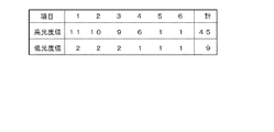
図5は、照射サイクルと光度値のリップルとの関係について説明するための図である。図4(B)に示した照射パターンにおいて、露光時間と非露光時間の比率が1:1であり、また、1照射サイクルにおける高光度値と低光度値の時間比率が1:1であり、1露光サイクル当たりの照射サイクルの数が6回(1〜3回が露光帯、4〜6回が非露光帯)であるとする。図5において「項目」とは照射サイクルの数を示しており、「高光度値」、「低光度値」は各照射サイクルにおけるパルス光の光度値の規格化値を示している。 FIG. 5 is a diagram for explaining the relationship between the irradiation cycle and the ripple of the luminous intensity value. In the irradiation pattern shown in FIG. 4B, the ratio of the exposure time to the non-exposure time is 1: 1, and the time ratio of the high luminous intensity value and the low luminous intensity value in one irradiation cycle is 1: 1. It is assumed that the number of irradiation cycles per one exposure cycle is 6 (1 to 3 is an exposure zone and 4 to 6 is a non-exposure zone). In FIG. 5, “item” indicates the number of irradiation cycles, and “high luminous intensity value” and “low luminous intensity value” indicate normalized values of the luminous intensity value of the pulsed light in each irradiation cycle.
連続点灯時の光度値は下記の計算に基づいて4.5(規格化値)となる。
連続点灯時の光度値=(45/6+9/6)/2=4.5
The luminous intensity value during continuous lighting is 4.5 (normalized value) based on the following calculation.
Luminous value at the time of continuous lighting = (45/6 + 9/6) /2=4.5
これに対して、高平均光度は下記の通り、6.0となる。
高光度値の平均値=(11+2+10+2+9+2)/6=6.0
On the other hand, the high average luminous intensity is 6.0 as follows.
Average value of high luminous intensity value = (11 + 2 + 10 + 2 + 9 + 2) /6=6.0
また、低平均光度は下記の通り、3.0となる。
低光度値の平均値=(6+1+5+1+4+1)/6=3.0
The low average luminous intensity is 3.0 as follows.
Average value of low light intensity value = (6 + 1 + 5 + 1 + 4 + 1) /6=3.0
これらから、リップル率は下記の通り、約1.3となる。
リップル率=高平均光度/連続点灯光度≒1.3
From these, the ripple rate is about 1.3 as follows.
Ripple rate = high average luminous intensity / continuous lighting luminous intensity ≒ 1.3
図6は、照射サイクルとフリッカーの関係を説明するための図である。ここでは、上記と同様に、露光時間と非露光時間の時間比を1:1、照射サイクルを6回とする。図示のように、各種時間は車載カメラ10のフレームレートに対応して決まる。例えば、車載カメラ10のフレームレートが30fpsであれば、1露光サイクルの期間は33.3msとなり、露光時間と非露光時間はそれぞれ16.7msとなる。照射サイクルの周波数は180Hz(=30×6)となる。1照射サイクルの時間は5.6ms、高光度値と低光度値の各時間は2.8msとなる。前照灯ユニット30による光の明暗周期は照射サイクルの周期に一致するので、フレームレートが30fpsであれば180Hzとなる。そして、露光帯における低光度率は18%(=2/11×100)、非露光帯における低光度率は17%(=1/6×100)となる。また、全体の低光度率は9.1%(=1/11×100)となるので、フリッカーを抑制できる。なお、光の明暗周期は100Hz以上となることが好ましい。フレームレートが60fps、90fps、120fpsの場合も同様である。
FIG. 6 is a diagram for explaining the relationship between the irradiation cycle and flicker. Here, similarly to the above, the time ratio between the exposure time and the non-exposure time is 1: 1, and the irradiation cycle is 6 times. As illustrated, various times are determined in accordance with the frame rate of the in-
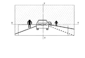
図7は、本実施形態の車載カメラにより撮影される画像について模式的に示す図である。また、図8は、比較例の車載カメラにより撮影される画像について模式的に示す図である。図8に示すように、夜間において前方車両が存在する場合には、前方車両の前照灯や尾灯による光に対応してオートゲイン機能により車載カメラ10の感度が低下することから、すれ違いビームが照射された領域以外の領域では非常に暗い画像となり、道路脇の歩行者などの非発光体の撮影、検出が困難となる。
FIG. 7 is a diagram schematically illustrating an image captured by the in-vehicle camera of the present embodiment. FIG. 8 is a diagram schematically illustrating an image captured by the in-vehicle camera of the comparative example. As shown in FIG. 8, when a vehicle ahead is present at night, the sensitivity of the in-
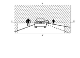
これに対して、図7に示すように本実施形態では、車載カメラ10の露光時間に対応させて複数のパルス光が照射されることにより、すれ違いビームの照射領域以外の領域においても実効的な光量が増加する。従って、オートゲイン機能により車載カメラ10の感度が低下しても道路脇の歩行者などの非発光体からの反射光量が増加するので、非発光体の撮影、検出が容易になる。
On the other hand, as shown in FIG. 7, in the present embodiment, a plurality of pulse lights are irradiated corresponding to the exposure time of the in-
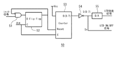
図9は、ノコギリ波を生成するための回路の一例を示す図である。この回路は、ANDゲート51、Dフリップフロップ52、カウンタ53、NOTゲート54、デジタルアナログ変換器(D/A)55を含んで構成されている。この回路は、制御装置20に含まれる。
FIG. 9 is a diagram illustrating an example of a circuit for generating a sawtooth wave. This circuit includes an AND
この回路50において、ANDゲート51は、一方入力端にシャッター信号(シャッターのオン/オフ状態を示す信号)が入力され、他方入力端にDフリップフロップ52の出力信号を反転した信号が入力されている。フリップフロップ52とカウンタ53は、クロック信号CLKにより同期して動作する。シャッター信号がANDゲート51を介してフリップフロップ52に入力されると、その立ち上がりエッジが検出されてフリップフロップ52の出力信号がカウンタ53へリセット信号として与えられる。なお、Dフリップフロップ52はクロック同期でなくとも動作する。
In this
カウンタ53は、常時加算されるように、入力端が電源電圧VCCに接続されている。カウンタ53のバス信号はNOTゲート54により反転され、減算される出力となり、デジタルアナログ変換器55によってアナログ信号に変換され、LEDの強度信号S(0:7)として出力される。また、Sx信号は、カウンタ数により反転するため、LEDのオン/オフ信号として出力される。S0信号を用いることで最も速くなる。これにより、ノコギリ波を生成することができる。
The
なお、上記回路と同様の動作は、マイコンを用いてテーブル値を参照する方法で実現することもでき、FPGAやCPLDなどのデジタル回路を用いて実現することもでき、ロジックICを用いて実現することもできる。 Note that the same operation as the above circuit can be realized by a method of referring to a table value using a microcomputer, can be realized using a digital circuit such as FPGA or CPLD, and is realized using a logic IC. You can also
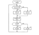
図10は、車両用前照灯システムの動作手順の一例を示すフローチャートである。なお、ここに示すフローチャートの動作は繰り返し実行されるものとする。 FIG. 10 is a flowchart illustrating an example of an operation procedure of the vehicle headlamp system. Note that the operations of the flowchart shown here are repeatedly executed.
上記の回路50において、車載カメラ10のシャッター信号の立ち上がりエッジが検出されると(ステップS11;YES)、カウンタ53がリセットされる(ステップS12)。他方で、シャッター信号の立ち上がりエッジが検出されない場合には(ステップS11;NO)、カウンタ53のカウント数が増加する(ステップS13)。
When the rising edge of the shutter signal of the in-
カウンタ53のカウント数に応じて、制御装置20によって点灯制御信号が生成され、出力される(ステップS14)。
In accordance with the count number of the
運転者の操作により自車両のヘッドランプスイッチがオンになっている場合には(ステップS15;YES)、制御装置20により前照灯ユニット(H/L)30が点灯するように制御される(ステップS16)。ヘッドランプスイッチがオフの場合には(ステップS15;NO)、制御装置20により前照灯ユニット(H/L)30が消灯するように制御される(ステップS17)。
When the headlamp switch of the host vehicle is turned on by the driver's operation (step S15; YES), the
図11は、変形実施例について説明するための図である。上記した図4と同様に、図11(A)は車載カメラによるシャッター動作のタイミングについて示す図であり、図11(B)は前照灯ユニットによる光の照射光度の時間変化を示す図である。この変形実施例は、照射光の変調に正弦波を用いた例である。具体的には、正弦波の波高値が相対的に高くなる期間を露光帯に対応付け、波高値が相対的に低くなる期間を非露光帯に対応づけて照射光を変調している。このような変形実施例によっても上記した実施形態と同様の効果が得られる。さらに、正弦波を変調に用いることで、照射光度の急激な変化が少なくなるので、フリッカーをより抑える効果が期待できる。 FIG. 11 is a diagram for explaining a modified embodiment. Similarly to FIG. 4 described above, FIG. 11 (A) is a diagram showing the timing of the shutter operation by the in-vehicle camera, and FIG. 11 (B) is a diagram showing the time change of the light irradiation intensity by the headlamp unit. . This modified embodiment is an example in which a sine wave is used for modulation of irradiation light. Specifically, the irradiation light is modulated by associating a period during which the peak value of the sine wave is relatively high with the exposure band and associating a period when the peak value is relatively low with the non-exposure band. The same effect as that of the above-described embodiment can be obtained by such a modified example. Furthermore, by using a sine wave for modulation, a rapid change in the irradiation light intensity is reduced, so that an effect of further suppressing flicker can be expected.
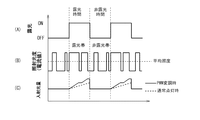
図12は、他の変形実施例について説明するための図である。上記した実施形態等では前照灯ユニット30による光の照射強度を電流制御していたが、PWM(Pulse Width Modulation)制御によって光の実質的な照射強度(照射量)を増減することもできる。上記した図4と同様に、図12(A)は車載カメラによるシャッター動作のタイミングについて示す図であり、図12(B)は前照灯ユニットによる光の照射光度の時間変化を示す図である。また、図12(C)は車載カメラの撮像素子への入射光量の時間変化を示す図である。
FIG. 12 is a diagram for explaining another modified embodiment. In the above-described embodiments and the like, the current irradiation intensity of the
図12(B)に示すように、露光帯におけるパルス幅を大きくすることで非発光体への実効的な照射光量を増加させ、シャッター開放時の撮像素子12への入射光量をより大きくすることができる。なお、PWM制御による照射光度の波高値は、通常の連続点灯時よりも大きいものとする。また、露光帯と非露光帯の全体としてのデューティ比は50%となっている。図12(C)に示すように、シャッター開放時の撮像素子12への入射光量は図示のように照射光度が高い期間において積分されて上昇していく。このときの入射光量は、通常の連続点灯時における入射光量よりも大きくなる。このため、被写体をより明るく撮像できる。このようなPWM制御を用いることで、デジタルアナログ変換器が不要となるため、点灯制御回路32をより簡素に(すなわち安価に)することができる。
As shown in FIG. 12B, by increasing the pulse width in the exposure band, the effective amount of light applied to the non-light emitter is increased, and the amount of light incident on the
図13は、PWM制御の一例を示す図である。図示の例では、露光サイクルの1周期を16分割し、さらに1つの単位を16分割している。各単位ごとのオン/オフ時間比は、例えば図14に示すように配分する。単位1〜8の時間がシャッター開、単位9〜16の時間がシャッター閉に対応しているとすると、シャッター開の時は点灯時間が長く、閉じている時は点灯時間が短くなる。図14に示す例では、点灯時間比は100:36となる。フリッカーを低減するには分割数がより細かいほうが好ましい。
FIG. 13 is a diagram illustrating an example of PWM control. In the example shown in the figure, one cycle of the exposure cycle is divided into 16, and one unit is further divided into 16. The on / off time ratio for each unit is distributed as shown in FIG. 14, for example. If the time of
図15は、PWM制御を行うための回路の一例を示す図である。この回路150は、ANDゲート51、Dフリップフロップ52、カウンタ53、コンパレータ(比較器)56、ORゲート57を含んで構成されている。この回路は、制御装置20に含まれる。この回路150は、上記した図9に示す回路50と一部構成が共通しており、当該共通する構成については同一符号が付されている。
FIG. 15 is a diagram illustrating an example of a circuit for performing PWM control. The
この回路150において、ANDゲート51、Dフリップフロップ52、カウンタ53からなる部分は上記した回路50と同様に動作するため、詳細な説明を省略する。コンパレータ56は、カウンタ53のバス信号の上位4ビットであるS(4:7)と下位4ビットであるS(0:3)とを比較し、下位4ビットが上位4ビット以上の場合に出力がハイ(高電位)となり、下位4ビットが上位4ビット未満の場合には出力がロー(低電位)となる。ORゲート57は、これらの出力の論理和に対応する信号を出力する。このORゲート57の出力を用いて、図15に示した波形を有するPWM信号を生成することができる。
In this
以上のような実施形態等によれば、歩行者等に対するグレアを低減しつつ歩行者等をより良好に撮影できるようにすることができる。 According to the embodiments and the like as described above, it is possible to photograph pedestrians and the like better while reducing glare for pedestrians and the like.
なお、本発明は上述した実施形態等の内容に限定されるものではなく、本発明の要旨の範囲内において種々に変形して実施をすることが可能である。例えば、上記した実施形態等においては本発明を車両用前照灯システムに適用した場合について例示していたが、本発明の適用範囲はこれに限定されず、例えば、後退時において点灯する後退灯とこれに連動して自車両の後方空間を撮影する車載カメラとを含む車両用灯具システムに対して本発明を適用することも可能である。 Note that the present invention is not limited to the contents of the above-described embodiment and the like, and various modifications can be made within the scope of the gist of the present invention. For example, in the above-described embodiments and the like, the case where the present invention is applied to a vehicle headlamp system has been illustrated, but the scope of the present invention is not limited to this, for example, a reverse lamp that is turned on during reverse It is also possible to apply the present invention to a vehicular lamp system that includes a vehicle-mounted camera that captures the rear space of the host vehicle in conjunction with this.
10:車載カメラ
11:撮影レンズ
12:撮像素子
13:カメラ制御回路
20:制御装置
30:前照灯ユニット
31:LEDモジュール
32:点灯制御回路
33:リフレクタ
34:シェード
35:投影レンズ
36:灯体ハウジング
37:アウターレンズ
DESCRIPTION OF SYMBOLS 10: Car-mounted camera 11: Shooting lens 12: Image sensor 13: Camera control circuit 20: Control apparatus 30: Headlamp unit 31: LED module 32: Lighting control circuit 33: Reflector 34: Shade 35: Projection lens 36: Lamp Housing 37: Outer lens
Claims (4)
前記周辺空間に対して光を照射する車両用灯具と、
前記車両用灯具の点灯状態を制御する制御装置と、
を含み、
前記車載カメラは、露光時間と非露光時間を有する単位露光サイクルを繰り返して当該露光時間に前記周辺空間を撮影するものであり、
前記制御装置は、前記車両用灯具により、前記露光時間と前記非露光時間の各々で複数のパルス光を照射されるように当該車両用灯具の点灯状態を制御するものであり、
前記露光時間における前記複数のパルス光の光度の平均的な大きさが相対的に高く、前記非露光時間における前記複数のパルス光の光度の平均的な大きさが相対的に低く設定されている、
車載システム。 An in-vehicle camera that captures the space around the vehicle,
A vehicular lamp that emits light to the surrounding space;
A control device for controlling the lighting state of the vehicular lamp;
Including
The in-vehicle camera repeats a unit exposure cycle having an exposure time and a non-exposure time, and images the surrounding space at the exposure time.
The control device controls the lighting state of the vehicular lamp so that a plurality of pulse lights are irradiated by the vehicular lamp at each of the exposure time and the non-exposure time,
The average magnitude of the light intensity of the plurality of pulsed light during the exposure time is set relatively high, and the average magnitude of the light intensity of the plurality of pulsed light during the non-exposure time is set relatively low. ,
In-vehicle system.
前記複数のパルス光は、各々の大きさが異なっており、
前記光度の平均的な大きさは、前記複数のパルス光の各々の大きさの平均値である、
請求項1に記載の車載システム。 The control device performs current control on the plurality of pulse lights at least in the exposure time,
The plurality of pulse lights have different sizes.
The average magnitude of the luminous intensity is an average value of the magnitudes of the plurality of pulse lights.
The in-vehicle system according to claim 1.
前記複数のパルス光は、各々の大きさが同じであり、
前記光度の平均的な大きさは、前記複数のパルス光によって得られる実効的な光度である、
請求項1に記載の車載システム。 The control device performs PWM control of the plurality of pulse lights at least in the exposure time,
Each of the plurality of pulse lights has the same size,
The average magnitude of the luminous intensity is an effective luminous intensity obtained by the plurality of pulse lights.
The in-vehicle system according to claim 1.
請求項1〜3の何れか1項に記載の車載システム。 The average magnitude of the luminous intensity of the plurality of pulsed light in the exposure time is set higher than the rated luminous intensity value at the time of continuous lighting of the vehicle lamp,
The in-vehicle system according to any one of claims 1 to 3.
Priority Applications (1)
| Application Number | Priority Date | Filing Date | Title |
|---|---|---|---|
| JP2016084323A JP2017193239A (en) | 2016-04-20 | 2016-04-20 | On-vehicle system |
Applications Claiming Priority (1)
| Application Number | Priority Date | Filing Date | Title |
|---|---|---|---|
| JP2016084323A JP2017193239A (en) | 2016-04-20 | 2016-04-20 | On-vehicle system |
Publications (1)
| Publication Number | Publication Date |
|---|---|
| JP2017193239A true JP2017193239A (en) | 2017-10-26 |
Family
ID=60155816
Family Applications (1)
| Application Number | Title | Priority Date | Filing Date |
|---|---|---|---|
| JP2016084323A Pending JP2017193239A (en) | 2016-04-20 | 2016-04-20 | On-vehicle system |
Country Status (1)
| Country | Link |
|---|---|
| JP (1) | JP2017193239A (en) |
Cited By (3)
| Publication number | Priority date | Publication date | Assignee | Title |
|---|---|---|---|---|
| WO2020246464A1 (en) * | 2019-06-07 | 2020-12-10 | スタンレー電気株式会社 | Vehicular lamp and vehicle front detection system |
| US11325525B2 (en) | 2020-07-03 | 2022-05-10 | Hyundai Mobis Co., Ltd. | Asynchronous control system in camera built-in lamp and method thereof |
| JP7444636B2 (en) | 2020-02-27 | 2024-03-06 | 株式会社小糸製作所 | vehicle headlights |
Citations (5)
| Publication number | Priority date | Publication date | Assignee | Title |
|---|---|---|---|---|
| JPS55126224A (en) * | 1979-03-23 | 1980-09-29 | Mamiya Koki Kk | Controlling method for light emission of strobe light emitting device |
| JPS60114039U (en) * | 1984-01-11 | 1985-08-01 | 日産自動車株式会社 | Visibility improvement device |
| JP2007223342A (en) * | 2006-02-21 | 2007-09-06 | Hitachi Ltd | Rear monitoring camera of vehicle and driving support device |
| JP2011084237A (en) * | 2009-10-19 | 2011-04-28 | Koito Mfg Co Ltd | Control system of vehicular headlamp |
| JP2014076726A (en) * | 2012-10-10 | 2014-05-01 | Fuji Electric Co Ltd | Headlight control device for electric automobile |
-
2016
- 2016-04-20 JP JP2016084323A patent/JP2017193239A/en active Pending
Patent Citations (5)
| Publication number | Priority date | Publication date | Assignee | Title |
|---|---|---|---|---|
| JPS55126224A (en) * | 1979-03-23 | 1980-09-29 | Mamiya Koki Kk | Controlling method for light emission of strobe light emitting device |
| JPS60114039U (en) * | 1984-01-11 | 1985-08-01 | 日産自動車株式会社 | Visibility improvement device |
| JP2007223342A (en) * | 2006-02-21 | 2007-09-06 | Hitachi Ltd | Rear monitoring camera of vehicle and driving support device |
| JP2011084237A (en) * | 2009-10-19 | 2011-04-28 | Koito Mfg Co Ltd | Control system of vehicular headlamp |
| JP2014076726A (en) * | 2012-10-10 | 2014-05-01 | Fuji Electric Co Ltd | Headlight control device for electric automobile |
Cited By (5)
| Publication number | Priority date | Publication date | Assignee | Title |
|---|---|---|---|---|
| WO2020246464A1 (en) * | 2019-06-07 | 2020-12-10 | スタンレー電気株式会社 | Vehicular lamp and vehicle front detection system |
| JP2020199831A (en) * | 2019-06-07 | 2020-12-17 | スタンレー電気株式会社 | Vehicular lighting fixture and vehicle forward detection system |
| JP7234042B2 (en) | 2019-06-07 | 2023-03-07 | スタンレー電気株式会社 | Vehicle lighting and vehicle forward detection system |
| JP7444636B2 (en) | 2020-02-27 | 2024-03-06 | 株式会社小糸製作所 | vehicle headlights |
| US11325525B2 (en) | 2020-07-03 | 2022-05-10 | Hyundai Mobis Co., Ltd. | Asynchronous control system in camera built-in lamp and method thereof |
Similar Documents
| Publication | Publication Date | Title |
|---|---|---|
| JP5955356B2 (en) | Lighting device | |
| JP3660877B2 (en) | Continuously variable headlight control | |
| US20120127313A1 (en) | Method and device for a vehicle-based illumination in insufficiently illuminated traffic environments | |
| CN110770081B (en) | Vehicle lamp system, vehicle lamp control device, and vehicle lamp control method | |
| JPWO2015033764A1 (en) | Vehicle lighting | |
| JP2018524225A (en) | Vehicle headlamp | |
| JP2009184642A (en) | Headlamp device for vehicle | |
| JP2017193239A (en) | On-vehicle system | |
| JPWO2019131055A1 (en) | Vehicle lighting system, vehicle lighting control device, and vehicle lighting control method | |
| JP5251680B2 (en) | Lighting control apparatus and program | |
| JP5416542B2 (en) | Control system for vehicle headlamps | |
| JP2009018804A (en) | Auxiliary equipment control device for automobile | |
| JP7267694B2 (en) | vehicle lamp | |
| JP6935815B2 (en) | Illumination imager | |
| JP2013154741A (en) | Lighting controller of vehicle headlight and vehicle headlight system | |
| KR102184335B1 (en) | Method and device for creating the high dynamic range images | |
| WO2022172860A1 (en) | Vehicle headlight | |
| JP2013147111A (en) | Lighting control device for vehicle front light, and vehicle front light system | |
| JP2019116202A (en) | Headlamp control device | |
| CN114026843A (en) | Vehicle-mounted infrared lighting device | |
| JP6944310B2 (en) | Specific object detection device | |
| JP2020142615A (en) | Control device of vehicle lighting fixture, control method of vehicle lighting fixture and vehicle lighting fixture system | |
| JP7458820B2 (en) | Vehicle headlights | |
| JP7406553B2 (en) | In-vehicle lighting system | |
| WO2022085683A1 (en) | Vehicular lamp system, light distribution control device, and light distribution control method |
Legal Events
| Date | Code | Title | Description |
|---|---|---|---|
| A621 | Written request for application examination |
Free format text: JAPANESE INTERMEDIATE CODE: A621 Effective date: 20190307 |
|
| A977 | Report on retrieval |
Free format text: JAPANESE INTERMEDIATE CODE: A971007 Effective date: 20191127 |
|
| A131 | Notification of reasons for refusal |
Free format text: JAPANESE INTERMEDIATE CODE: A131 Effective date: 20191203 |
|
| A02 | Decision of refusal |
Free format text: JAPANESE INTERMEDIATE CODE: A02 Effective date: 20200528 |