JP2017192984A - Laser processing apparatus and laser processing method - Google Patents
Laser processing apparatus and laser processing method Download PDFInfo
- Publication number
- JP2017192984A JP2017192984A JP2017076866A JP2017076866A JP2017192984A JP 2017192984 A JP2017192984 A JP 2017192984A JP 2017076866 A JP2017076866 A JP 2017076866A JP 2017076866 A JP2017076866 A JP 2017076866A JP 2017192984 A JP2017192984 A JP 2017192984A
- Authority
- JP
- Japan
- Prior art keywords
- protective film
- laser processing
- processing
- laser
- shared
- Prior art date
- Legal status (The legal status is an assumption and is not a legal conclusion. Google has not performed a legal analysis and makes no representation as to the accuracy of the status listed.)
- Granted
Links
Images


Classifications
-
- B—PERFORMING OPERATIONS; TRANSPORTING
- B23—MACHINE TOOLS; METAL-WORKING NOT OTHERWISE PROVIDED FOR
- B23K—SOLDERING OR UNSOLDERING; WELDING; CLADDING OR PLATING BY SOLDERING OR WELDING; CUTTING BY APPLYING HEAT LOCALLY, e.g. FLAME CUTTING; WORKING BY LASER BEAM
- B23K26/00—Working by laser beam, e.g. welding, cutting or boring
- B23K26/20—Bonding
- B23K26/21—Bonding by welding
- B23K26/24—Seam welding
- B23K26/28—Seam welding of curved planar seams
-
- B—PERFORMING OPERATIONS; TRANSPORTING
- B23—MACHINE TOOLS; METAL-WORKING NOT OTHERWISE PROVIDED FOR
- B23K—SOLDERING OR UNSOLDERING; WELDING; CLADDING OR PLATING BY SOLDERING OR WELDING; CUTTING BY APPLYING HEAT LOCALLY, e.g. FLAME CUTTING; WORKING BY LASER BEAM
- B23K26/00—Working by laser beam, e.g. welding, cutting or boring
- B23K26/36—Removing material
- B23K26/38—Removing material by boring or cutting
-
- B—PERFORMING OPERATIONS; TRANSPORTING
- B23—MACHINE TOOLS; METAL-WORKING NOT OTHERWISE PROVIDED FOR
- B23K—SOLDERING OR UNSOLDERING; WELDING; CLADDING OR PLATING BY SOLDERING OR WELDING; CUTTING BY APPLYING HEAT LOCALLY, e.g. FLAME CUTTING; WORKING BY LASER BEAM
- B23K26/00—Working by laser beam, e.g. welding, cutting or boring
- B23K26/08—Devices involving relative movement between laser beam and workpiece
- B23K26/0869—Devices involving movement of the laser head in at least one axial direction
- B23K26/0876—Devices involving movement of the laser head in at least one axial direction in at least two axial directions
- B23K26/0884—Devices involving movement of the laser head in at least one axial direction in at least two axial directions in at least three axial directions, e.g. manipulators, robots
-
- B—PERFORMING OPERATIONS; TRANSPORTING
- B23—MACHINE TOOLS; METAL-WORKING NOT OTHERWISE PROVIDED FOR
- B23K—SOLDERING OR UNSOLDERING; WELDING; CLADDING OR PLATING BY SOLDERING OR WELDING; CUTTING BY APPLYING HEAT LOCALLY, e.g. FLAME CUTTING; WORKING BY LASER BEAM
- B23K26/00—Working by laser beam, e.g. welding, cutting or boring
- B23K26/20—Bonding
- B23K26/21—Bonding by welding
- B23K26/24—Seam welding
- B23K26/244—Overlap seam welding
-
- B—PERFORMING OPERATIONS; TRANSPORTING
- B23—MACHINE TOOLS; METAL-WORKING NOT OTHERWISE PROVIDED FOR
- B23K—SOLDERING OR UNSOLDERING; WELDING; CLADDING OR PLATING BY SOLDERING OR WELDING; CUTTING BY APPLYING HEAT LOCALLY, e.g. FLAME CUTTING; WORKING BY LASER BEAM
- B23K26/00—Working by laser beam, e.g. welding, cutting or boring
- B23K26/36—Removing material
- B23K26/361—Removing material for deburring or mechanical trimming
-
- B—PERFORMING OPERATIONS; TRANSPORTING
- B23—MACHINE TOOLS; METAL-WORKING NOT OTHERWISE PROVIDED FOR
- B23K—SOLDERING OR UNSOLDERING; WELDING; CLADDING OR PLATING BY SOLDERING OR WELDING; CUTTING BY APPLYING HEAT LOCALLY, e.g. FLAME CUTTING; WORKING BY LASER BEAM
- B23K26/00—Working by laser beam, e.g. welding, cutting or boring
- B23K26/36—Removing material
- B23K26/362—Laser etching
-
- B—PERFORMING OPERATIONS; TRANSPORTING
- B23—MACHINE TOOLS; METAL-WORKING NOT OTHERWISE PROVIDED FOR
- B23K—SOLDERING OR UNSOLDERING; WELDING; CLADDING OR PLATING BY SOLDERING OR WELDING; CUTTING BY APPLYING HEAT LOCALLY, e.g. FLAME CUTTING; WORKING BY LASER BEAM
- B23K26/00—Working by laser beam, e.g. welding, cutting or boring
- B23K26/60—Preliminary treatment
-
- B—PERFORMING OPERATIONS; TRANSPORTING
- B23—MACHINE TOOLS; METAL-WORKING NOT OTHERWISE PROVIDED FOR
- B23K—SOLDERING OR UNSOLDERING; WELDING; CLADDING OR PLATING BY SOLDERING OR WELDING; CUTTING BY APPLYING HEAT LOCALLY, e.g. FLAME CUTTING; WORKING BY LASER BEAM
- B23K2101/00—Articles made by soldering, welding or cutting
- B23K2101/18—Sheet panels
-
- B—PERFORMING OPERATIONS; TRANSPORTING
- B23—MACHINE TOOLS; METAL-WORKING NOT OTHERWISE PROVIDED FOR
- B23K—SOLDERING OR UNSOLDERING; WELDING; CLADDING OR PLATING BY SOLDERING OR WELDING; CUTTING BY APPLYING HEAT LOCALLY, e.g. FLAME CUTTING; WORKING BY LASER BEAM
- B23K2101/00—Articles made by soldering, welding or cutting
- B23K2101/34—Coated articles ; Surface treated articles
Landscapes
- Engineering & Computer Science (AREA)
- Physics & Mathematics (AREA)
- Optics & Photonics (AREA)
- Plasma & Fusion (AREA)
- Mechanical Engineering (AREA)
- Robotics (AREA)
- Laser Beam Processing (AREA)
Abstract
Description
本発明は、保護フィルムが貼られたワークを加工する場合に、部品同士が接触する共有部分などの剥がす必要のある部分の保護フィルムを自動で切断するレーザ加工装置およびレーザ加工方法に関する。 The present invention relates to a laser processing apparatus and a laser processing method for automatically cutting a protective film of a part that needs to be peeled off, such as a shared part where parts are in contact with each other, when processing a workpiece to which a protective film is attached.
近年、板金製品の製造工程への要求品位が高くなり、ステンレス素材等のワークに保護フィルムを貼った状態でのワーク加工が増加している。 In recent years, the quality required for the manufacturing process of sheet metal products has increased, and workpiece processing with a protective film applied to a workpiece made of stainless steel or the like has increased.
板金レーザ加工の工程において、部品同士が接触する共有部分等の保護フィルムを剥がす必要のある部分があり、従来では手作業で、保護フィルムの部分撤去を行っていた。 In the sheet metal laser processing step, there is a portion that needs to be peeled off a protective film such as a shared portion where parts are in contact with each other, and conventionally, the protective film has been partially removed manually.
ここで、ワークにおいて部分的に保護フィルムを剥がす必要のあるケースとは、加工後に、別部品を取り付ける予定のある部品や、へミング(つぶし)曲げで隠れる部品や、溶接の熱で焼けてしまう部分等を有するケースである。 Here, the case where the protective film needs to be partially peeled off from the workpiece is a part that is scheduled to be attached with another part after processing, a part hidden by hemming (crushing) bending, or burned by the heat of welding. This is a case having a portion or the like.
従来の手作業での保護フィルムの部分撤去は、フィルムを部分的に剥がして持ち上げ、カッターナイフ等で母材をキズつけないように切断するようにしており、手間がかかり、作業者の負担増となる問題があった。 Conventional manual removal of the protective film involves partly peeling the film and lifting it up, and cutting it with a cutter knife so as not to scratch the base material, which takes time and increases the burden on the operator. There was a problem.
本発明は、上記した事情に着目してなされたものであり、その目的とするところは、保護フィルムが貼られたワークをレーザ加工する場合に、部品同士が接触する共有部分等の剥がす必要のある部分の保護フィルムを自動で判断して切断することにより、保護フィルムの部分撤去の作業性を向上させることができるレーザ加工装置およびレーザ加工方法を提供することにある。 The present invention has been made paying attention to the above-mentioned circumstances, and the purpose of the present invention is to peel off a shared portion where components are in contact with each other when laser processing a workpiece with a protective film attached thereto. An object of the present invention is to provide a laser processing apparatus and a laser processing method capable of improving the workability of partial removal of a protective film by automatically judging and cutting a protective film of a certain part.
本発明は上述の問題を解決するためのものであり、本発明の特徴は、保護フィルムが貼られたワークに対してレーザ加工を行うレーザ加工装置であって、加工プログラムを含む加工情報に基づいて、前記保護フィルムをカットするためのレーザ加工が必要な共有部分が有るか否かを判別し、前記保護フィルムをカットするレーザ加工が必要な共有部分が有る場合、前記保護フィルムをカットするレーザ加工が必要な部分のレーザ加工処理を前記加工プログラムに追加することである。 This invention is for solving the above-mentioned problem, The characteristic of this invention is a laser processing apparatus which performs laser processing with respect to the workpiece | work with which the protective film was affixed, Comprising: Based on the processing information containing a processing program And determining whether or not there is a common part that needs laser processing for cutting the protective film, and if there is a common part that needs laser processing to cut the protective film, a laser that cuts the protective film The laser processing for the part that needs to be processed is added to the processing program.
本発明の他の特徴は、前記保護フィルムをカットするためのレーザ加工が、レーザマーキング加工であることである。 Another feature of the present invention is that laser processing for cutting the protective film is laser marking processing.
本発明の他の特徴は、前記保護フィルムをカットするためのレーザ加工が必要な共有部分が、別部品を取り付ける予定の部分であることである。 Another feature of the present invention is that the shared part that requires laser processing for cutting the protective film is a part to which another part is to be attached.
本発明の他の特徴は、前記保護フィルムをカットするためのレーザ加工が必要な共有部分が、へミング(つぶし)曲げを行う部分であることである。 Another feature of the present invention is that the shared portion that needs laser processing for cutting the protective film is a portion that performs hemming (crushing) bending.
本発明の他の特徴は、前記保護フィルムをカットするためのレーザ加工が必要な共有部分が、溶接を行う部分であることである。 Another feature of the present invention is that the common part that requires laser processing for cutting the protective film is a part to be welded.
本発明の他の特徴は、前記保護フィルムをカットするためのレーザ加工が必要な共有部分が、スタッドボルトの溶接による取付け部分であることである。 Another feature of the present invention is that the common part that requires laser processing for cutting the protective film is an attachment part by welding a stud bolt.
本発明の他の特徴は、前記加工情報には、加工プログラムの他に、加工するワークの材質、加工寸法、3Dモデル情報の加工に必要な情報が含まれると共に、溶接設定やスタッドボルト取付設定のレーザ加工後のワークWの加工処理情報やワークWに貼られた保護フィルムに関する情報が含まれ、その保護フィルムに関する情報には、保護フィルムの種類が含まれることである。 Another feature of the present invention is that the machining information includes information necessary for machining the workpiece material, machining dimensions, and 3D model information in addition to the machining program, as well as welding settings and stud bolt attachment settings. The processing information of the workpiece W after laser processing and information on the protective film attached to the workpiece W are included, and the information on the protective film includes the type of the protective film.
本発明の他の特徴は、保護フィルムが貼られたワークに対してレーザ加工を行うレーザ加工方法であって、加工プログラムを含む加工情報に基づいて、前記保護フィルムをカットするためのレーザ加工が必要な共有部分が有るか否かを判別する工程と、前記保護フィルムをカットするレーザ加工が必要な共有部分が有る場合、前記保護フィルムをカットするレーザ加工が必要な共有部分のレーザ加工処理を前記加工プログラムに追加する工程とを有することである。 Another feature of the present invention is a laser processing method for performing laser processing on a workpiece on which a protective film is pasted, wherein laser processing for cutting the protective film is performed based on processing information including a processing program. A step of determining whether or not there is a necessary shared part, and if there is a shared part that requires laser processing to cut the protective film, laser processing of the shared part that requires laser processing to cut the protective film is performed. Adding to the machining program.
本発明の他の特徴は、前記保護フィルムをカットするレーザ加工が必要な共有部分が、溶接を行う共有部分である場合、溶接線からの熱の拡散範囲に応じて、前記保護フィルムをカットするレーザ加工が必要な共有部分の形状を調整することである。 Another feature of the present invention is that, when the shared part that requires laser processing to cut the protective film is a shared part to be welded, the protective film is cut according to the diffusion range of heat from the weld line. It is to adjust the shape of the common part that needs laser processing.
本発明の他の特徴は、前記保護フィルムをカットするレーザ加工が必要な共有部分が、溶接を行う共有部分である場合、溶接ヘッドからのレーザ光の照射方向に応じて、前記保護フィルムをカットするレーザ加工が必要な共有部分の形状を変えることである。 Another feature of the present invention is that when the shared part that requires laser processing to cut the protective film is a shared part to be welded, the protective film is cut according to the irradiation direction of the laser light from the welding head. The shape of the common part that needs laser processing is changed.
本発明によれば、保護フィルムが貼られたワークを加工する場合に、剥がす必要のある共有部分の保護フィルムを自動で判断して切断することにより、保護フィルムの共有部分撤去の作業性を著しく向上させることができる。 According to the present invention, when processing a workpiece to which a protective film has been applied, the workability of removing the shared portion of the protective film is remarkably reduced by automatically judging and cutting the protective film of the shared portion that needs to be peeled off. Can be improved.
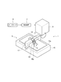
図1は、本発明を実施したレーザ加工装置の全体斜視図である。 FIG. 1 is an overall perspective view of a laser processing apparatus embodying the present invention.
図1に示すように、レーザ加工装置1は、被加工材であるワークWにレーザ光を照射して、ワークWに対し開孔等のレーザ加工を施し、ワークWから所定の部品等を作製するものである。
As shown in FIG. 1, the
レーザ加工装置1は、レーザ光源であるレーザ発振器3と、レーザ発振器3から出力されたレーザ光をワークWに照射してワークWに加工を施す本体部5と、レーザ加工装置1の全体の動作を制御する制御装置7と、を有している。なお、制御装置7には、外部のデータサーバ9などが接続されている。
The
レーザ発振器3は、制御装置7の指示により、レーザ光を発振し、レーザ発振器3で生成されたレーザ光は、プロセスファイバ11を介して加工ヘッド13に供給される。
The
本体部5は、ワークWを載置する載置面15aを有する加工テーブル15と、加工テーブル15に設けられ、その載置面15aに沿う一方向(X軸方向)に移動するX軸キャリッジ17と、を有している。
The
X軸キャリッジ17には、載置面15aに沿い、かつX軸方向と直交するY軸方向に移動するY軸キャリッジ19が設けられており、Y軸キャリッジ19には、加工ヘッド13がZ軸方向(X軸及びY軸に直交する方向)に移動可能に取り付けられている。
The
X軸キャリッジ17,Y軸キャリッジ19,及び加工ヘッド13は、それぞれ制御装置7の制御下にある駆動部(図示せず)の駆動により互いに独立して移動するようになっている。
The
加工ヘッド13は、X軸キャリッジ17とY軸キャリッジ19との協働動作により、ワークWに対向する範囲において、ワークWの表面に沿う2次元的移動が可能とされ、ワークWの所望の加工点Wpに対してレーザ光Lを所定の焦点位置をもって照射し、加工を施す。
The
図2は、図1に示した制御装置7の概略構成図である。
FIG. 2 is a schematic configuration diagram of the
図2に示すように、制御装置7は、コンピュータからなり、ROM23およびRAM25が接続されたCPU27を有しており、CPU27には、さらに、キーボードのような入力装置29とデイスプレイのような表示装置31と外部のデータサーバ9などが接続されている。
As shown in FIG. 2, the
なお、制御装置7には、外部のデータサーバ9などから加工プログラムを含む加工情報が供給される。
Note that machining information including a machining program is supplied to the
ここで、加工情報には、加工プログラムの他に、加工するワークWの材質、加工寸法、3Dモデル情報等の加工に必要な情報が含まれると共に、溶接設定やスタッドボルト取付設定等のレーザ加工後のワークWの加工処理情報やワークWに貼られた保護フィルムに関する情報が含まれる。 Here, in addition to the machining program, the machining information includes information necessary for machining such as the material of the workpiece W to be machined, machining dimensions, and 3D model information, as well as laser machining such as welding settings and stud bolt attachment settings. Information on the processing of the subsequent workpiece W and information on the protective film attached to the workpiece W are included.
そして、その保護フィルムに関する情報には、保護フィルムの種類などが含まれ、後述するように、制御装置7は、加工に必要な情報と溶接設定やスタッドボルト取付設定等のレーザ加工後のワークWの加工処理情報とワークWに貼られた保護フィルムに関する情報に基づいて、ワークWから作成される部品における共有部分に関する情報を作成し、その共有部分の情報に基づいて、レーザ加工で保護フィルムをカットするレーザマーキング加工を制御する。
And the information regarding the protective film includes the type of the protective film and the like. As will be described later, the
すなわち、部品の共有部分とは、加工後に、部品同士が接触する部分のことであり、その部品同士が接触する共有部分に、予めレーザマーキング加工を施して、保護フィルムを剥がし易くしようとするものである。 That is, the shared part of the part is a part where the parts come into contact with each other after processing, and the shared part where the parts come into contact with each other is preliminarily laser-marked so as to easily peel off the protective film. It is.
なお、上述した加工に必要な情報には、展開図等の図面情報が含まれる。このレーザマーキング加工により、塩化ビニール等で作られた保護フィルムがカットされる。 Note that the information necessary for the above-described processing includes drawing information such as a development view. By this laser marking process, a protective film made of vinyl chloride or the like is cut.
すなわち、この制御装置7では、CPU27が、入力装置29よりのオペレータからの指示に従い、加工プログラムを含む加工情報に基づくレーザ加工装置1の制御を行い、レーザマーキング加工を含むレーザ加工をワークWに施す。
That is, in this
次に、制御装置7によって実行される保護フィルムをカットするレーザマーキング加工について説明する。なお、この場合、前もって保護フィルムが有るか否かの判定が行われ、保護フィルムが有る場合の処理となっている。
Next, laser marking processing for cutting the protective film executed by the
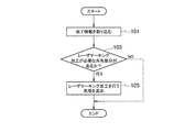
図3は、制御装置7によって実行される保護フィルムをカットするレーザマーキング加工の追加のフローチャートである。
FIG. 3 is an additional flowchart of the laser marking process performed by the
図3のステップ101において、制御装置7は、外部のデータサーバ9などから加工プログラムを含む加工情報を取り込む。
In
ここで、加工情報には、加工プログラムの他に、加工するワークWの材質、加工寸法、3Dモデル情報等の加工に必要な情報が含まれると共に、溶接設定やスタッドボルト取付設定等のレーザ加工後のワークWの加工処理情報やワークWに貼られた保護フィルムに関する情報が含まれ、その保護フィルムに関する情報には、保護フィルムの種類などが含まれる。 Here, in addition to the machining program, the machining information includes information necessary for machining such as the material of the workpiece W to be machined, machining dimensions, and 3D model information, as well as laser machining such as welding settings and stud bolt attachment settings. Information on the processing of the subsequent workpiece W and information on the protective film attached to the workpiece W are included, and the information on the protective film includes the type of the protective film.
そして、ステップ103において、制御装置7は、加工情報に基づいて、保護フィルムをカットするレーザマーキング加工が必要な共有部分が有るか否かを判別し、保護フィルムをカットするレーザマーキング加工が必要な共有部分が有る場合、ステップ105において、制御装置7は、その共有部分の外周に沿ったレーザマーキング加工を行う処理を加工プログラムに追加する。
In
なお、上記レーザマーキング加工は、通常のレーザ加工の後に行われるように設定されるが、通常のレーザ加工の前に行うように設定しても良い。 The laser marking process is set to be performed after the normal laser process, but may be set to be performed before the normal laser process.
次に、上記ステップ103および上記ステップ105における工程の詳細について説明する。
Next, details of the
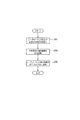
図4は、上記ステップ103におけるレーザマーキング加工が必要な共有部分が有るか否かを判別する工程および上記ステップ105におけるレーザマーキング加工する処理を加工プログラムに追加する工程のフローチャートである。
FIG. 4 is a flowchart of the process of determining whether or not there is a shared part that needs laser marking processing in
図4のステップ201において、制御装置7は、取り込まれた加工プログラムを含む加工情報に基づいて、保護フィルムをカットするレーザマーキング加工が必要な共有部分を検出する。
In
すなわち、加工情報には、加工プログラムの他に、加工するワークWの材質、加工寸法、3Dモデル情報等の加工に必要な情報が含まれると共に、溶接設定やスタッドボルト取付設定等のレーザ加工後のワークWの加工処理情報やワークWに貼られた保護フィルムに関する情報が含まれているので、その加工情報に基づいて、制御装置7は、溶接等のため加工後に部品同士が接触する共有部分を検出する。
That is, in addition to the machining program, the machining information includes information necessary for machining such as the material of the workpiece W to be machined, machining dimensions, and 3D model information, and after laser machining such as welding setting and stud bolt setting. Since the processing information of the workpiece W and information about the protective film attached to the workpiece W are included, the
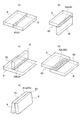
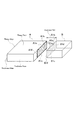
なお、加工後に部品同士が接触する共有部分としては、図5に示すような種類がある。すなわち、図5(a)に示すように、部品Aの端面A1と部品Bと端面B1とが接触して共有部分を形成する端面接続(Butt joint)、図5(b)に示すように、部品Aの平面A2のコーナー部分A2aと部品Bの端面B1とが接触して共有部分を形成するコーナー接続(Corner joint)、図5(c)に示すように、部品Aの平面A2の中央部分A2bと部品Bの端面B1とが接触して共有部分を形成するT型接続(T joint)、図5(d)に示すように、部品Aの平面A2の一部A2cと部品Bの平面B2の一部B2aとが接触して共有部分を形成する重ね接続(Lap joint)、図5(e)に示すように、部品Aの端面A1のエッジ部A1aと部品Bの端面B1のエッジ部B1aとが接触して共有部分を形成するエッジ接続(Edge joint)等があげられる。 In addition, there exists a kind as shown in FIG. 5 as a shared part which components contact after processing. That is, as shown in FIG. 5 (a), the end face A1, the part B, and the end face B1 of the part A are in contact with each other to form a shared part (Butt joint), as shown in FIG. 5 (b), Corner connection (Corner joint) in which the corner portion A2a of the plane A2 of the part A and the end surface B1 of the part B come into contact to form a shared portion, as shown in FIG. 5C, the central portion of the plane A2 of the part A T-type connection (T joint) in which A2b and end face B1 of component B come into contact to form a shared portion, as shown in FIG. 5 (d), part A2c of plane A2 of component A and plane B2 of component B 5 (e), the edge portion A1a of the end surface A1 of the component A and the edge portion B1a of the end surface B1 of the component B, as shown in FIG. And shared part in contact with Forming edge connection (Edge joint), and the like.
次に、ステップ203において、制御装置7のCPU27は、上記ステップ201で検出された共有部分の構成情報を接合パターンとして生成し、RAM25に記憶する。
Next, in
図5は、加工後に部品同士が接触する共有部分の種類の説明図であり、図5(a)〜図5(d)において、共有部分は斜線で示している。なお、図5(e)では、エッジ接続であるので実線となる。 FIG. 5 is an explanatory diagram of the types of shared portions where parts come into contact with each other after processing. In FIGS. 5 (a) to 5 (d), the shared portions are indicated by diagonal lines. In FIG. 5E, since it is edge connection, it becomes a solid line.
ここで、図5(a)に示すような端面接続(Butt joint)を例に取って説明すると、図6に示すような、端面接続として、部品Aの端面A1と部品Bの端面B1とが接触する共有面について、図7に示すような、共有面の構成情報が取得される。 Here, the end face connection (But joint) as shown in FIG. 5A will be described as an example. As shown in FIG. 6, the end face A1 of the part A and the end face B1 of the part B are connected as shown in FIG. With respect to the shared surface that comes into contact, the configuration information of the shared surface as shown in FIG. 7 is acquired.
なお、図6に示すような、部品Aの端面A1には、保護フィルムが貼られているものとする。 In addition, the protective film shall be affixed on end surface A1 of the component A as shown in FIG.
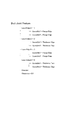
すなわち、図6に示す部品Aの端面A1の共有面A1bを囲む第1の端線A1cおよび部品Bの端面B1の共有面B1bを囲む第1の端線B1cが、図7に示すButt Joint Feature における Local Edge.ID=1 として取得される。 That is, the first end line A1c surrounding the shared surface A1b of the end surface A1 of the component A shown in FIG. 6 and the first end line B1c surrounding the shared surface B1b of the end surface B1 of the component B are represented by the Butt Joint Feature shown in FIG. In Local Edge. Obtained as ID = 1.
このLocal Edge.ID=1においては、第1の端線A1cのパラメータ GeomAttr1 が、属性 Flange Edge となり、第1の端線B1cのパラメータ GeomAttr2 が、属性 Flange Edge となる。 This Local Edge. In the case of ID = 1, the parameter GeomAttr1 of the first end line A1c becomes the attribute “Flange Edge”, and the parameter GeomAtr2 of the first end line B1c becomes the attribute “Flange Edge”.
同様に、第2の端線A1d、B1d、第3の端線A1e、B1e、第4の端線A1f、B1fのLocal Edge.ID=2〜4のパラメータおよび属性が取得され、図7に示すような共有面の構成情報となる。これらの情報をもとに、共有部分の種類が判別される。 Similarly, the Local Edge. Of the second end lines A1d, B1d, the third end lines A1e, B1e, and the fourth end lines A1f, B1f. Parameters and attributes of ID = 2 to 4 are acquired, and the shared surface configuration information as shown in FIG. 7 is obtained. Based on these pieces of information, the type of shared part is determined.
図6は、端面接続として、部品Aの端面A1と部品Bの端面B1とが接触する共有面の説明図であり、図7は、図6に示した共有面の構成情報の説明図である。 6 is an explanatory diagram of a shared surface where the end surface A1 of the component A and the end surface B1 of the component B are in contact with each other as an end surface connection, and FIG. 7 is an explanatory diagram of the configuration information of the shared surface shown in FIG. .
次に、ステップ205において、制御装置7のCPU27は、上記ステップ203で生成されRAM25に記憶された共有部分の構成情報に基づいて、レーザマーキング加工する処理を加工プログラムに追加する。
Next, in
すなわち、上述した共有部分の構成情報に基づいて、その共有部分の外周に沿ったレーザマーキング加工を行う処理プログラムを加工プログラムに追加する。 That is, based on the above-described configuration information of the shared portion, a processing program for performing laser marking along the outer periphery of the shared portion is added to the processing program.
上記レーザマーキング加工は、通常のレーザ加工の後に行われるように追加されても良いし、通常のレーザ加工の前に行うように追加しても良い。 The laser marking process may be added to be performed after normal laser processing, or may be added to be performed before normal laser processing.
図6に示すような、部品Aの端面A1と部品Bの端面B1とが接触する共有面の場合、その共有面の外周に沿った線の内、第1の端線A1c〜第3の端線A1eは、部品Aのエッジとなるので、第4の端線A1fに沿ったレーザマーキング加工を行うようにしている。 In the case of a shared surface where the end surface A1 of the component A and the end surface B1 of the component B are in contact as shown in FIG. 6, the first end line A1c to the third end of the lines along the outer periphery of the shared surface Since the line A1e becomes the edge of the part A, laser marking processing is performed along the fourth end line A1f.
また、部品Aと部品Bとの取り付け誤差を考慮して、レーザマーキング加工を、第4の端線A1fの少し外側に行うようにしても良い。 Further, in consideration of an attachment error between the parts A and B, the laser marking process may be performed slightly outside the fourth end line A1f.
次に、共有部分に基づくレーザマーキング加工の具体例について説明する。 Next, a specific example of laser marking processing based on the shared portion will be described.
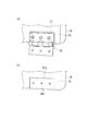
図8〜図11は、共有部分に基づくレーザマーキング加工の具体例の説明図である。 8-11 is explanatory drawing of the specific example of the laser marking process based on a shared part.
図8は、端面接続として、別部品を取り付ける予定の共有部分が有る場合の説明図である。 FIG. 8 is an explanatory diagram in the case where there is a shared portion to which another component is to be attached as an end face connection.
図8(a)に示すように、レーザ加工後のワークWの加工処理において、ワークWに別部品33を取り付ける場合、制御装置7は、レーザ加工後のワークWの加工処理情報から、別部品を取り付ける予定の共有部分の構成情報を生成し、その構成情報に基づいて、レーザマーキング加工を加工プログラムに追加する。その結果、図8(b)に示すように、別部品33が取り付けられる予定の共有部分W1の外周W1aにレーザマーキング加工が行われる。
As shown in FIG. 8A, in the processing of the workpiece W after laser processing, when the
これにより、レーザ加工後に、レーザマーキング加工を行った共有部分の保護フィルムを簡単に取り除くことができ、図8(a)に示すように、保護フィルム35を取り除いた共有部分37に別部品33を取り付けることができる。
Thereby, the protective film of the shared part which performed the laser marking process can be easily removed after laser processing, and as shown in FIG. 8A, another
すなわち、保護フィルム35が付いたままでの別部品33の取り付けによる不都合を回避することができる。
That is, inconvenience due to the attachment of the
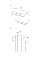
図9は、端面接続として、へミング(つぶし)曲げを行う共有部分が有る場合の説明図である。 FIG. 9 is an explanatory diagram in the case where there is a shared portion that performs hemming (crushing) bending as the end face connection.
図9(a)に示すように、へミング(つぶし)曲げを行う共有部分が有る場合、制御装置7は、へミング(つぶし)曲げを行う予定の共有部分の構成情報を生成し、その構成情報に基づいて、レーザマーキング加工を加工プログラムに追加する。その結果、図9(b)に示すように、へミング(つぶし)曲げを行う共有部分39の重なり合う領域W2の外周W2aにレーザマーキング加工が行われる。
As shown in FIG. 9 (a), when there is a shared part that performs hemming (crushing) bending, the
これにより、レーザ加工後に、レーザマーキング加工を行った共有部分の保護フィルムを簡単に取り除くことができ、図9(b)に示すように、重なり合う領域W2において保護フィルム35を取り除いた状態でのへミング(つぶし)曲げを行うことができる。
As a result, after the laser processing, the protective film of the shared portion subjected to the laser marking processing can be easily removed, and as shown in FIG. 9B, the
すなわち、保護フィルム35が付いたままでのへミング(つぶし)曲げにより、へミング(つぶし)曲げを行う共有部分39の保護フィルム35の残留による不都合を回避することができる。
That is, the inconvenience due to the remaining of the
図10は、エッジ接続として、エッジ溶接を行う共有部分がある場合の説明図である。 FIG. 10 is an explanatory diagram in the case where there is a shared portion for performing edge welding as edge connection.
図10(a)に示すように、エッジ溶接を行う共有部分が有る場合、制御装置7は、溶接設定情報から、溶接を行う共有部分の構成情報を生成し、その構成情報に基づいて、レーザマーキング加工を加工プログラムに追加する。その結果、図9(b)に示すように、溶接を行う共有部分41の外周W3aにレーザマーキング加工が行われる。
As shown in FIG. 10A, when there is a shared portion for performing edge welding, the
ここで、溶接を行う共有部分41の外周W3aの決定は、以下に説明する溶接を行う部分41における保護フィルム35の剥がし幅Lを設定する処理により行われる。
Here, the determination of the outer periphery W3a of the shared
すなわち、溶接を行う共有部分41における保護フィルム35の剥がし幅を設定する処理は、溶接設定情報に基づく溶接動作設定時に、制御装置7が、溶接ヘッド43よりの入熱量(方向性)を予測し、最小限の剥がし幅Lを溶接線45に対して不均等に設定する。
That is, in the process of setting the peeling width of the
より詳しく説明すると、図10(a)に示すように、溶接時の溶接ヘッド43よりの照射方向により、溶接を行う共有部分41の溶接線45からの熱の拡散量が異る。図10(b)に示すように、溶接ヘッド43からのレーザ光等の照射方向が、溶接線45の右側から入射する場合、溶接線45の右側の熱の拡散量より溶接線45の左側の熱の拡散量の方が多くなる。
More specifically, as shown in FIG. 10A, the amount of heat diffusion from the
従って、制御装置7は、溶接設定情報に基づいて、図10(b)に示すように、溶接線45の右側の剥がし幅L2より溶接線45の左側の剥がし幅L1の方が大きくなるように、溶接を行う共有部分41の外周W3aを決定してレーザマーキング加工を行う。
Therefore, based on the welding setting information, the
これにより、レーザ加工後に、レーザマーキング加工を行った共有部分の保護フィルムを簡単に取り除くことができ、図10(b)に示すように、溶接線45の右側の剥がし幅L2より溶接線45の右側の剥がし幅L1の方が大きくなるように保護フィルム35を剥がすことができるので、保護フィルム35が焦げて後が残ったりすることが無い。
Thereby, the protective film of the shared part which performed the laser marking process can be easily removed after the laser processing, and as shown in FIG. 10 (b), the
なお、保護フィルム35の剥がし幅Lは、ワークWの板厚や材質により決定するようにしても良い。すなわち、ワークWの板厚や材質が、溶接に大きな熱量を必要とする場合には、剥がし幅Lを大きく設定し、溶接に小さな熱量しか必要としない場合には、剥がし幅Lを小さく設定するようにしても良い。
The peeling width L of the
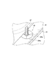
図11は、端面接続として、スタッドボルトの溶接による取付け共有部分が有る場合の説明図である。 FIG. 11 is an explanatory diagram in the case where there is an attachment shared portion by welding a stud bolt as an end face connection.
図11に示すように、スタッドボルトの溶接による取付け共有部分が有る場合、制御装置7は、3Dモデル情報から、スタッドボルト47の溶接による取付け共有部分の構成情報を生成し、その構成情報に基づいて、レーザマーキング加工を加工プログラムに追加する。
As shown in FIG. 11, when there is a shared mounting portion by welding the stud bolt, the
その結果、図11に示すように、スタッドボルト47の溶接による取付け共有部分49の外周W4aにレーザマーキング加工を行う。
As a result, as shown in FIG. 11, laser marking is performed on the outer periphery W <b> 4 a of the attachment shared
これにより、レーザ加工後に、レーザマーキング加工を行った共有部分の保護フィルムを簡単に取り除くことができ、図11に示すように、スタッドボルト47の溶接による取付け共有部分49の外周W4aにおいて保護フィルム35を取り除いた状態でのスタッドボルト47の溶接を行うことができる。
Thereby, after the laser processing, the protective film of the shared portion subjected to the laser marking processing can be easily removed, and as shown in FIG. 11, the
従って、保護フィルム35が焦げて後が残ったりするこが無い。
Therefore, the
なお、スタッドボルト47の溶接による取付け共有部分49を判別処理においても、制御装置7が、溶接ヘッドよりの入熱量(方向性)を予測し、最小限の剥がし幅Lをスタッドボルト47に対して不均等に設定するようにしても良い。
Even in the process of discriminating the attachment shared
また、図11において、W4bは、スタッドボルト47の溶接箇所を示すマークである。
Further, in FIG. 11, W4b is a mark indicating the welding location of the
上記実施形態によれば、保護フィルムをカットすることが必要な共有部分に、予めレーザマーキング加工を行って、保護フィルムを剥がし易くしているので、保護フィルムの共有部分撤去の作業性を著しく向上させることができる。 According to the above-described embodiment, since the protective film is easily peeled off by performing laser marking in advance on the shared portion that needs to be cut off, the workability of removing the shared portion of the protective film is significantly improved. Can be made.
この発明は前述の発明の実施の形態に限定されることなく、適宜な変更を行うことにより、その他の態様で実施し得るものである。 The present invention is not limited to the embodiments of the invention described above, and can be implemented in other modes by making appropriate modifications.
1 レーザ加工装置
3 レーザ発振器
5 本体部
7 制御装置
9 データサーバ
11 プロセスファイバ
13 加工ヘッド
23 ROM
25 RAM
27 CPU
29 入力装置
31 表示装置
33 別部品
35 保護フィルム
DESCRIPTION OF
25 RAM
27 CPU
29
Claims (10)
加工プログラムを含む加工情報に基づいて、前記保護フィルムをカットするためのレーザ加工が必要な共有部分が有るか否かを判別し、前記保護フィルムをカットするレーザ加工が必要な共有部分が有る場合、前記保護フィルムをカットするレーザ加工が必要な共有部分のレーザ加工を行う処理を前記加工プログラムに追加することを特徴とするレーザ加工装置。 A laser processing apparatus that performs laser processing on a workpiece on which a protective film is attached,
When there is a shared part that needs laser processing to cut the protective film, based on processing information including a processing program, to determine whether there is a shared part that needs laser processing to cut the protective film A laser processing apparatus for adding to the processing program a process for performing laser processing on a shared portion that requires laser processing to cut the protective film.
加工プログラムを含む加工情報に基づいて、前記保護フィルムをカットするためのレーザ加工が必要な共有部分が有るか否かを判別する工程と、前記保護フィルムをカットするレーザ加工が必要な共有部分が有る場合、前記保護フィルムをカットするレーザ加工が必要な共有部分のレーザ加工処理を前記加工プログラムに追加する工程とを有することを特徴とするレーザ加工方法。 A laser processing method for performing laser processing on a workpiece on which a protective film is attached,
Based on processing information including a processing program, a step of determining whether there is a shared portion that needs laser processing for cutting the protective film, and a shared portion that requires laser processing to cut the protective film And a step of adding, to the processing program, a laser processing for a shared portion that requires laser processing to cut the protective film.
Priority Applications (4)
| Application Number | Priority Date | Filing Date | Title |
|---|---|---|---|
| PCT/JP2017/015075 WO2017179643A1 (en) | 2016-04-15 | 2017-04-13 | Laser processing device and laser processing method |
| CN201780023145.5A CN109070274B (en) | 2016-04-15 | 2017-04-13 | Laser processing apparatus and laser processing method |
| US16/093,035 US10710198B2 (en) | 2016-04-15 | 2017-04-13 | Laser processing device and laser processing method |
| EP17782456.2A EP3444062B1 (en) | 2016-04-15 | 2017-04-13 | Laser processing device and laser processing method |
Applications Claiming Priority (2)
| Application Number | Priority Date | Filing Date | Title |
|---|---|---|---|
| JP2016082050 | 2016-04-15 | ||
| JP2016082050 | 2016-04-15 |
Publications (2)
| Publication Number | Publication Date |
|---|---|
| JP6190982B1 JP6190982B1 (en) | 2017-08-30 |
| JP2017192984A true JP2017192984A (en) | 2017-10-26 |
Family
ID=59720502
Family Applications (1)
| Application Number | Title | Priority Date | Filing Date |
|---|---|---|---|
| JP2017076866A Active JP6190982B1 (en) | 2016-04-15 | 2017-04-07 | Laser processing apparatus and laser processing method |
Country Status (5)
| Country | Link |
|---|---|
| US (1) | US10710198B2 (en) |
| EP (1) | EP3444062B1 (en) |
| JP (1) | JP6190982B1 (en) |
| CN (1) | CN109070274B (en) |
| WO (1) | WO2017179643A1 (en) |
Families Citing this family (2)
| Publication number | Priority date | Publication date | Assignee | Title |
|---|---|---|---|---|
| CN110340523A (en) * | 2019-07-26 | 2019-10-18 | 深圳市海镭激光科技有限公司 | A kind of intelligence jointed fiber bonding machine |
| CN111451631B (en) * | 2020-04-02 | 2021-10-08 | 佛山根固激光科技有限公司 | Laser welding heads and welding equipment |
Citations (4)
| Publication number | Priority date | Publication date | Assignee | Title |
|---|---|---|---|---|
| JPH07241688A (en) * | 1994-03-04 | 1995-09-19 | Fanuc Ltd | Laser processing method |
| JP2001212681A (en) * | 2000-02-04 | 2001-08-07 | Shibuya Kogyo Co Ltd | Laser processing method |
| JP2010194602A (en) * | 2009-02-27 | 2010-09-09 | Ogata Esumetsuku:Kk | Protective sheet for workpiece to be laser-machined and workpiece to be laser-machined stuck with the same |
| JP2014097519A (en) * | 2012-11-14 | 2014-05-29 | Amada Co Ltd | System and method for managing material with protective film |
Family Cites Families (10)
| Publication number | Priority date | Publication date | Assignee | Title |
|---|---|---|---|---|
| US3790744A (en) * | 1971-07-19 | 1974-02-05 | American Can Co | Method of forming a line of weakness in a multilayer laminate |
| JP2009155625A (en) * | 2007-12-07 | 2009-07-16 | Denki Kagaku Kogyo Kk | Protective film, laminated film and processing method using the same |
| CN102510788B (en) * | 2010-06-14 | 2014-12-24 | 三菱电机株式会社 | Laser processing device and laser processing method |
| DE102010044128A1 (en) * | 2010-11-18 | 2012-05-24 | Bundesdruckerei Gmbh | Laser apparatus and method for processing objects with a controllable in the pulse energy laser |
| KR20120137868A (en) * | 2011-06-13 | 2012-12-24 | 삼성디스플레이 주식회사 | Apparatus for peeling protection film for flat display module and method for peeling film |
| JP5787653B2 (en) * | 2011-07-20 | 2015-09-30 | 株式会社ディスコ | Laser processing equipment |
| JP2013078785A (en) * | 2011-10-04 | 2013-05-02 | Disco Corp | Method of detecting condensing spot position in laser beam processing apparatus |
| CN102699541A (en) * | 2012-05-11 | 2012-10-03 | 东莞光谷茂和激光技术有限公司 | A laser cutting process of coated metal plate |
| JP6222903B2 (en) * | 2012-08-17 | 2017-11-01 | 株式会社ディスコ | Laser processing equipment |
| JP6190708B2 (en) | 2013-11-29 | 2017-08-30 | 株式会社アマダホールディングス | Laser processing method and apparatus |
-
2017
- 2017-04-07 JP JP2017076866A patent/JP6190982B1/en active Active
- 2017-04-13 EP EP17782456.2A patent/EP3444062B1/en active Active
- 2017-04-13 CN CN201780023145.5A patent/CN109070274B/en active Active
- 2017-04-13 US US16/093,035 patent/US10710198B2/en active Active
- 2017-04-13 WO PCT/JP2017/015075 patent/WO2017179643A1/en not_active Ceased
Patent Citations (4)
| Publication number | Priority date | Publication date | Assignee | Title |
|---|---|---|---|---|
| JPH07241688A (en) * | 1994-03-04 | 1995-09-19 | Fanuc Ltd | Laser processing method |
| JP2001212681A (en) * | 2000-02-04 | 2001-08-07 | Shibuya Kogyo Co Ltd | Laser processing method |
| JP2010194602A (en) * | 2009-02-27 | 2010-09-09 | Ogata Esumetsuku:Kk | Protective sheet for workpiece to be laser-machined and workpiece to be laser-machined stuck with the same |
| JP2014097519A (en) * | 2012-11-14 | 2014-05-29 | Amada Co Ltd | System and method for managing material with protective film |
Also Published As
| Publication number | Publication date |
|---|---|
| WO2017179643A1 (en) | 2017-10-19 |
| EP3444062A1 (en) | 2019-02-20 |
| CN109070274B (en) | 2020-07-07 |
| JP6190982B1 (en) | 2017-08-30 |
| CN109070274A (en) | 2018-12-21 |
| US10710198B2 (en) | 2020-07-14 |
| EP3444062A4 (en) | 2019-05-08 |
| US20190118298A1 (en) | 2019-04-25 |
| EP3444062B1 (en) | 2021-01-13 |
Similar Documents
| Publication | Publication Date | Title |
|---|---|---|
| JP3162255B2 (en) | Laser processing method and apparatus | |
| CN106853554B (en) | Intelligent laser system of processing and its processing method | |
| US12569936B2 (en) | Processes and devices for beam processing of plate-shaped or tubular workpieces | |
| US12504740B2 (en) | Method and apparatus for determining cutting parameters for a laser cutting machine | |
| WO2015072107A1 (en) | Laser welding condition determination method and laser welding device | |
| JP5518095B2 (en) | Sheet metal component with corners with three edges suitable for laser welding, corresponding sheet metal blank and method for manufacturing and optimizing sheet metal blank | |
| JP6190982B1 (en) | Laser processing apparatus and laser processing method | |
| US10974346B2 (en) | Laser cutting method and machine, and automatic programing apparatus | |
| CN105290622A (en) | A laser cutting machine capable of self-adaptive cutting and a laser cutting method using the same | |
| US11007596B2 (en) | Program creation device, welding system, and program creation method | |
| JP5356106B2 (en) | Numerical control data generator | |
| JP5909355B2 (en) | Automatic programming apparatus and method for laser processing machine and laser processing system | |
| JP2018167294A (en) | Laser processing device and plate material processing method | |
| JPS62286680A (en) | Butt welding method for aluminum thin plate | |
| TWI491574B (en) | Method of cutting brittle workpiece and cutting device | |
| US6133541A (en) | Method for cutting Y bevels | |
| JP2016043391A (en) | Laser arc hybrid welding method | |
| CN205200816U (en) | A self-adaptive cutting laser cutting machine | |
| JP4325434B2 (en) | Composite welding apparatus, welding method thereof and composite welding system | |
| CN115555720A (en) | Laser welding method and workpiece | |
| KR102349328B1 (en) | Laser assisted micro-machining system and method for micro-machining using the same | |
| JP6314054B2 (en) | Automatic programming device in laser processing system | |
| Sarah | Comparative Study of Robotic and Manual Welding in A Low Volume-High Mix Manufacturing Environment: Case Study of Cross Head | |
| Suggula | Comparative Study of Robotic And Manual Welding In A Low Volume-High Mix Manufacturing Environment: Case Study Of Tail Gate | |
| JP6854184B2 (en) | Laser welding method |
Legal Events
| Date | Code | Title | Description |
|---|---|---|---|
| TRDD | Decision of grant or rejection written | ||
| A01 | Written decision to grant a patent or to grant a registration (utility model) |
Free format text: JAPANESE INTERMEDIATE CODE: A01 Effective date: 20170711 |
|
| A61 | First payment of annual fees (during grant procedure) |
Free format text: JAPANESE INTERMEDIATE CODE: A61 Effective date: 20170807 |
|
| R150 | Certificate of patent or registration of utility model |
Ref document number: 6190982 Country of ref document: JP Free format text: JAPANESE INTERMEDIATE CODE: R150 |
|
| S533 | Written request for registration of change of name |
Free format text: JAPANESE INTERMEDIATE CODE: R313533 |
|
| R350 | Written notification of registration of transfer |
Free format text: JAPANESE INTERMEDIATE CODE: R350 |