JP2017192932A - Coating method for forming a plurality of adjacent regions with uniform thickness - Google Patents
Coating method for forming a plurality of adjacent regions with uniform thickness Download PDFInfo
- Publication number
- JP2017192932A JP2017192932A JP2016105900A JP2016105900A JP2017192932A JP 2017192932 A JP2017192932 A JP 2017192932A JP 2016105900 A JP2016105900 A JP 2016105900A JP 2016105900 A JP2016105900 A JP 2016105900A JP 2017192932 A JP2017192932 A JP 2017192932A
- Authority
- JP
- Japan
- Prior art keywords
- boundary line
- region
- outer boundary
- arbitrary point
- coating
- Prior art date
- Legal status (The legal status is an assumption and is not a legal conclusion. Google has not performed a legal analysis and makes no representation as to the accuracy of the status listed.)
- Granted
Links
Images


Classifications
-
- B—PERFORMING OPERATIONS; TRANSPORTING
- B41—PRINTING; LINING MACHINES; TYPEWRITERS; STAMPS
- B41J—TYPEWRITERS; SELECTIVE PRINTING MECHANISMS, i.e. MECHANISMS PRINTING OTHERWISE THAN FROM A FORME; CORRECTION OF TYPOGRAPHICAL ERRORS
- B41J3/00—Typewriters or selective printing or marking mechanisms characterised by the purpose for which they are constructed
- B41J3/407—Typewriters or selective printing or marking mechanisms characterised by the purpose for which they are constructed for marking on special material
- B41J3/4073—Printing on three-dimensional objects not being in sheet or web form, e.g. spherical or cubic objects
-
- B—PERFORMING OPERATIONS; TRANSPORTING
- B41—PRINTING; LINING MACHINES; TYPEWRITERS; STAMPS
- B41J—TYPEWRITERS; SELECTIVE PRINTING MECHANISMS, i.e. MECHANISMS PRINTING OTHERWISE THAN FROM A FORME; CORRECTION OF TYPOGRAPHICAL ERRORS
- B41J2/00—Typewriters or selective printing mechanisms characterised by the printing or marking process for which they are designed
- B41J2/005—Typewriters or selective printing mechanisms characterised by the printing or marking process for which they are designed characterised by bringing liquid or particles selectively into contact with a printing material
- B41J2/01—Ink jet
- B41J2/205—Ink jet for printing a discrete number of tones
- B41J2/2054—Ink jet for printing a discrete number of tones by the variation of dot disposition or characteristics, e.g. dot number density, dot shape
-
- B—PERFORMING OPERATIONS; TRANSPORTING
- B41—PRINTING; LINING MACHINES; TYPEWRITERS; STAMPS
- B41J—TYPEWRITERS; SELECTIVE PRINTING MECHANISMS, i.e. MECHANISMS PRINTING OTHERWISE THAN FROM A FORME; CORRECTION OF TYPOGRAPHICAL ERRORS
- B41J2/00—Typewriters or selective printing mechanisms characterised by the printing or marking process for which they are designed
- B41J2/005—Typewriters or selective printing mechanisms characterised by the printing or marking process for which they are designed characterised by bringing liquid or particles selectively into contact with a printing material
- B41J2/01—Ink jet
- B41J2/21—Ink jet for multi-colour printing
- B41J2/2132—Print quality control characterised by dot disposition, e.g. for reducing white stripes or banding
Abstract
Description
本発明は、隣接する複数領域を均一な厚みで塗膜を形成する塗装方法に関し、さらに詳しくは、塗装面を複数に区分してインクジェットプリントヘッドによる塗装を行った場合でも隣接する複数領域をそれぞれ均一な厚さの塗膜で塗装することが可能な塗装方法に関する。 The present invention relates to a coating method for forming a coating film with a uniform thickness in a plurality of adjacent regions, and more specifically, even when a plurality of adjacent regions are coated even when an inkjet print head is used for coating with a coating surface being divided into a plurality of coating surfaces. The present invention relates to a coating method capable of being coated with a uniform thickness coating film.
ミクロンオーダで均一な厚さの塗膜を得るための塗装、例えば、自動車の車体への塗装はスプレーガンによる塗装が一般的である。しかし、スプレーガンによる塗装は、塗料がミスト状(霧状)に吐出されるため、被塗装面に固着する塗料の量とスプレーガンから吐出される全塗料の量との割合、つまり塗着効率を100%にすることはできない。近年の最も優れたベル型静電スプレーガンによる塗装であってもその塗着効率は90%程度である。残りの約10%はミストとなって空中に無駄に散逸しており、しかも、この散逸した塗料を回収するために多大の設備投資が必要とされているのが現状である。これに対し、インクジェットプリントヘッドによる塗装は、塗料がミスト状ではなくドット状に吐出されるため、塗着効率100%の塗装を実現できるものと期待されている。その一例としては特許文献1,2に示すものがある。
Coating for obtaining a coating film having a uniform thickness on the order of microns, for example, coating on the body of an automobile, is generally performed by a spray gun. However, since painting with a spray gun is performed in a mist (mist) form, the ratio between the amount of paint adhering to the surface to be painted and the amount of all paint ejected from the spray gun, that is, the coating efficiency Cannot be made 100%. Even with the most excellent bell-type electrostatic spray gun in recent years, the coating efficiency is about 90%. The remaining approximately 10% is mist and is dissipated wastefully in the air, and a large amount of capital investment is required to recover the dissipated paint. On the other hand, painting with an ink jet print head is expected to realize painting with a coating efficiency of 100% because the paint is ejected in dots instead of mist. Examples thereof include those shown in
インクジェットプリントヘッドによる塗装の概略について図19を参照しつつ説明する。図19は従来のインクジェットプリント装置の構成例を示す斜視図であり、概略として、塗料を吐出するインクジェットプリントヘッド31と、インクジェットプリントヘッド31をX軸方向へ往復動させるX軸移動機構33と、インクジェットプリントヘッド31をY軸方向へ往復動させるY軸移動機構34と備えて構成されている。インクジェットプリントヘッド31は、X軸移動機構33とY軸移動によって構成されるX−Yテーブル35に支持されて被塗装物32の表面上をX−Y方向に移動し、その過程でインクジェットプリントヘッド31の図示しない複数のノズルからドット状の塗料が被塗装物32の被塗装面に向かって下方に吐出されることにより塗膜が被塗装面に形成される。
An outline of coating by the ink jet print head will be described with reference to FIG. FIG. 19 is a perspective view illustrating a configuration example of a conventional inkjet printing apparatus. As a general rule, an
このようなインクジェットプリント装置30による塗装にも大きな問題がある。この問題について以下に説明する。インクジェットプリントヘッド31からドット状に吐出される塗料はインクジェットプリントヘッド31から被塗装面までの距離が近い場合には、塗料は100%が被塗装面に固着する。しかし、インクジェットプリントヘッド31から被塗装面までの距離が遠い場合には、ドット状に吐出された塗料は空気抵抗を受けて途中からミスト状に変化して被塗装面に100%到達せず、一部が空中に散逸して無駄になる塗料が発生する。
There is a big problem also in the coating by such an
例えば、図20に示すような曲面を有する被塗装物32に対してインクジェットプリントヘッド31を左右方向に移動させて塗装を行う場合、インクジェットプリントヘッド31がほぼ中央に位置しているときには、被塗装面32aはインクジェットプリントヘッド31の下方に接近しており、インクジェットプリントヘッド31から吐出される塗料はドット状のまま被塗装面32aに到達する。一方、インクジェットプリントヘッド31が図20の例えば右側(破線で示すインクジェットプリントヘッドの位置)に位置しているときには、被塗装面32aはインクジェットプリントヘッド31から遠く離れており、インクジェットプリントヘッド31から吐出される塗料は途中からミスト状に変化して空中に散逸し、塗料は被塗装面32aに100%到達しない。曲面を有する被塗装面32aの全域をミストレスに塗装するためには、図21に示すように、被塗装面32aを例えばA,B,C,Dの様に複数の領域に分割し、被塗装物32の保持位置を変えることによりA〜Dの各領域をインクジェットプリントヘッド31に順次近接対向させた上で塗装を行う必要がある。つまり、1つの領域はインクジェットプリントヘッド31から吐出された塗料がドット状に固着可能なインクジェットプリントヘッド31から被塗装面32aまでの距離を確保できる範囲となるように分割する。
For example, when coating is performed by moving the
図22は領域Aを塗装する状態を示す説明図である。図示されるように、初めにインクジェットプリントヘッド31に領域Aを近接対向するように位置させた状態で塗装を実施し、これが終わったら、他の領域B〜Dを順次インクジェットプリントヘッド31にそれぞれ近接対向するように位置させた後、領域B〜Dを塗装することになる。このように複数の領域に分割して塗装する方法は、被塗装面32aがインクジェットプリントヘッド31の移動可能範囲を越えるような大きなサイズの被塗装物に対しても同様に適用することが可能である。
FIG. 22 is an explanatory view showing a state where the region A is painted. As shown in the drawing, coating is first performed with the region A positioned close to and opposed to the
ここで、二つの領域の間の境界線付近における塗装について図23を参照しつつ説明する。領域Aとそれに隣接する領域Bとの境界線T付近に対する塗装は、理想的には図23(a)に示すように、まず、単位面積当たり所定量の塗料を領域Aから境界線Tまで吐出し、領域Aから境界線Tまで厚さが均一の塗膜35を形成する。塗膜35の厚みは境界線Tで垂直状にゼロに落ちるようにする。次に、図23(b)に示すように、境界線Tから領域Bまで単位面積当たり所定量の塗料をインクジェットプリントヘッド31から吐出し、厚さが均一な塗膜36を形成する。この塗膜36は境界線Tでゼロから垂直状に立ち上がるようにする。以上説明した図23(a)に示す塗膜35と図23(b)に示す塗膜36とを合成すれば、図23(c)に示すように、領域Aから領域Bに至る領域において均一な厚さの塗膜37が形成されることになる。
Here, the coating in the vicinity of the boundary line between the two regions will be described with reference to FIG. As shown in FIG. 23 (a), the coating of the area A and the area B adjacent to the area B is ideally performed by first discharging a predetermined amount of paint from the area A to the boundary line T as shown in FIG. Then, the
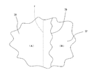
しかしながら、実際にはインクジェットプリントヘッド31によって図23(c)に示すような塗膜を得るべく単位面積当たり所定量の塗料を領域Aから境界線T上まで吐出しても、図23(d)に示すように、得られる塗膜38の厚さは境界線Tの両側で崩れた形となる。その原因は塗料の表面張力及び粘性に限りがあるためである。加えて、被塗装面32aの物性の違いによって塗料の崩れ方が不規則になり、境界線T付近を上面から見ると、図24に示すように、塗膜38の端39は不規則に波打った状態となる。例えば、塗膜厚50μmを得るために単位面積当たり所定量の塗料をインクジェットプリントヘッド31から吐出した場合、塗膜38の端39の波は境界線Tから近い所で約0.5mm、遠い所で約1.0mmとなる。
However, in practice, even if a predetermined amount of paint per unit area is discharged from the region A to the boundary line T so as to obtain a coating film as shown in FIG. As shown in FIG. 4, the thickness of the coating film 38 obtained is a shape that collapses on both sides of the boundary line T. This is because the surface tension and viscosity of the paint are limited. In addition, the manner in which the paint collapses becomes irregular due to the difference in physical properties of the surface to be coated 32a, and when the vicinity of the boundary line T is viewed from above, the
上述のように、領域Aの境界線T付近から隣接する領域Bにおける塗料の吐出量をどのように制御しても、境界線T付近において均一な厚さの塗膜を得ることは困難であった。因みに、境界線T上から領域Bまで単位面積当たり同じ所定量の塗料を吐出した場合、最初の塗膜と合成して得られる塗膜31は、図25に示すように、境界線Tの左側では凹みが発生し、右側では突起が発生して塗膜を均一にできない。しかも、上述したように、この部分を上方から見ると不規則な波状の凹みラインと不規則な波状の突起ラインが境界線Tに平行して生じている。
As described above, it is difficult to obtain a coating film having a uniform thickness in the vicinity of the boundary line T no matter how the paint discharge amount in the area B adjacent from the vicinity of the boundary line T in the area A is controlled. It was. Incidentally, when the same predetermined amount of paint per unit area is discharged from the boundary line T to the region B, the
また、被塗装面の湾曲の状態によっては2つの領域が隣接する場合だけでなく、3領域あるいはそれ以上の領域が互いに隣接するようにして分割される場合もある。複数の領域が隣接する交点付近では不規則となるため均一の塗膜を形成することはさらに困難であった。 Further, depending on the curved state of the surface to be coated, not only the two regions are adjacent to each other, but also the three regions or more regions may be divided so as to be adjacent to each other. It is more difficult to form a uniform coating film because it becomes irregular in the vicinity of an intersection where a plurality of regions are adjacent.
そこで、本発明は、かかる問題点に鑑みなされたもので、塗装面を複数に区分した各領域をインクジェットプリントヘッドでそれぞれ塗装を行った場合でも被塗装面全体を均一な厚さの塗膜で塗装することが可能な塗装方法を提供することを目的とする。 Therefore, the present invention has been made in view of such problems, and even when each region obtained by dividing a painted surface into a plurality of regions is coated with an inkjet print head, the entire coated surface is coated with a uniform thickness. It aims at providing the painting method which can be painted.
上記課題を解決するために請求項1に記載の発明は、被塗装面を複数の領域に分割し、分割された各領域をそれぞれインクジェットプリントヘッドから吐出される塗料が散逸しない距離で前記インクジェットプリントヘッドに近接対向させた状態で前記インクジェットプリントヘッドから吐出される塗料によって塗装する塗装方法であって、所定の領域とこれに隣接する他の領域との境界線の両側、または、前記境界線と前記他の領域同士の境界線に基づいて仮想的に設定された仮想境界線の両側の少なくとも塗膜の厚さの50倍以上の長さ隔てた位置に前記境界線、または、前記境界線と仮想境界線に平行な内側境界線及び外側境界線をそれぞれ想定し、前記内側境界線と前記外側境界線との間の塗装は塗装対象である所定の領域内に存在する内側境界線又は外側境界線からそれとは反対側の外側境界線又は内側境界線に向かって塗料の吐出量を次第に漸減させて反対側の外側境界線又は内側境界線上でゼロとなるように塗料の吐出量を制御することにより前記被塗装面を全体として均一な所定の厚さの塗膜で塗装することを特徴とする隣接する複数領域を均一な厚みで塗膜を形成する塗装方法を提供する。
In order to solve the above-mentioned problem, the invention according to
上記課題を解決するために請求項2に記載の発明は、被塗装面を複数の領域に分割し、分割された各領域をそれぞれインクジェットプリントヘッドから吐出される塗料が散逸しない距離で前記インクジェットプリントヘッドに近接対向させた状態で前記インクジェットプリントヘッドから吐出される塗料によって塗装する塗装方法であって、前記被塗装面を分割したある領域とこれに隣接する領域との間の境界線Tの内側の当該ある領域内に前記境界線Tから少なくとも塗膜の厚さの50倍以上の長さの所定の距離Lを隔てて想定される仮想的な内側境界線T1iと、前記境界線T1の外側であって前記ある領域に隣接する領域内に当該境界線T1から前記所定の距離L1と等距離を隔てて想定される仮想的な外側境界線T1oとの間に存在する点Qの前記内側境界線T1iからの距離をL1とし、前記所定の厚さの塗膜を形成するために必要な単位面積当たりのインクジェットプリントヘッドからの塗料吐出量をPとした場合、点Qにおける塗料吐出量PQを以下の式に従って算出して塗装を行うことにより前記境界線Tを介して隣接する領域を均一の塗膜で塗装することを特徴とする隣接する複数領域を均一な厚みで塗膜を形成する塗装方法を提供する。
。
PQ=P×(2L1−m)/2L1
In order to solve the above-mentioned problem, the invention according to
.
P Q = P × (2L 1 −m) / 2L 1
上記課題を解決するために請求項3に記載の発明は、被塗装面を複数の領域に分割し、分割された各領域をそれぞれインクジェットプリントヘッドから吐出される塗料が散逸しない距離で前記インクジェットプリントヘッドに近接対向させた状態で前記インクジェットプリントヘッドから吐出される塗料によって塗装する塗装方法であって、3つの前記領域が一つの交点(O)を有して互いに隣接する場合において、前記3つの領域のうちの所定の領域である前記第1の領域(A)とこれに隣接する第2の領域(B)との間の境界線T1の内側に位置する当該第1の領域(A)内に前記境界線T1から少なくとも塗膜の厚さの50倍以上の長さの距離L1を隔てた位置に仮想的な第1の内側境界線T1iを想定すると共に、前記第1の境界線T1の外側に位置する前記第2の領域(B)内に当該境界線T1から前記所定の距離L1と等距離を隔てた位置に仮想的な第1の外側境界線T1oを想定し、
前記被塗装面の前記第1の領域(A)とこれに隣接する他の第3の領域(C)との間の境界線T2の内側に位置する当該第1の領域(A)内に前記境界線T2から前記距離L1を隔てた位置に仮想的な第2の内側境界線T2iを想定すると共に、前記第2の境界線T2の外側に位置する前記第3の領域(C)内に当該境界線T2から前記距離L1と等距離を隔てた位置に仮想的な第2の外側境界線T2oを想定し、前記第1の内側境界線T1iと前記第1の外側境界線T1o及び前記第2の内側境界線T2iと前記第2の外側境界線T2oをそれぞれ延長することによって形成される4つの交点(a,b,c,d)を頂点とする四角形の4つの辺のうち、前記第2の外側境界線T2oによって形成される辺(bc)の中点eを通り且つ前記第2の領域(B)と前記第3の領域(C)との間の境界線T3に平行な仮境界線T3’を想定し、さらに前記第2の外側境界線T2oと前記第1の内側境界線T1iとの交点bを通って前記仮境界線T3’と平行な第3の内側境界線T3’iを想定すると共に、前記第2の外側境界線T2oと前記第1の外側境界線T1oとの交点cを通って前記仮境界線T3’と平行な第3の外側境界線T3’oを想定し、前記第3の内側境界線T3’iと前記仮境界線T3’との間の距離及び前記第3の外側境界線T3’oとの間の距離をそれぞれL2とし、前記被塗装面上の任意の点Qが前記第1の内側境界線T1iと前記第1の外側境界線T1oとの間に存在する場合における前記第1の内側境界線T1iからの距離をmとし、前記任意の点Qが前記第2の内側境界線T2iと前記第2の外側境界線T2oとの間に存在する場合における前記第2の内側境界線T2iからの距離をnとし、前記点Qが前記第3の内側境界線T3’iと前記第3の外側境界線T3’oとの間に存在する場合における前記第3の内側境界線T3’iからの距離をsとし、所定の厚さの塗膜を形成するために必要な単位面積当たりのインクジェットプリントヘッドからの塗料吐出量をPとした場合、前記第1から第3の各領域(A,B,C)の塗装は、それぞれ前記任意の点Qにおける塗料吐出量PQを以下の式に従って算出して塗装を行うことにより前記被塗装面を全体として均一な所定の厚さの塗膜で塗装することを特徴とする隣接する複数領域を均一な厚みで塗膜を形成する塗装方法を提供する。
(1)第1の領域(A)の塗装
前記任意の点Qが、前記第1の内側境界線T1iと前記第2の内側境界線T2iの内側の当該第1の領域(A)内に位置する場合
PQ=P
前記任意の点Qが、前記第1の内側境界線T1iと前記第1の外側境界線T1oとの間に位置する場合
PQ=P×(2L1−m)/2L1
前記任意の点Qが、前記第2の内側境界線T2iと前記第2の外側境界線T2oとの間に位置する場合
PQ=P×(2L1−n)/2L1
但し、前記任意の点Qが、前記四角形(a,b,c,d)の内側に位置する場合
PQ=P×{(2L1−m)/2L1}×{(2L1−n)/2L1}
(2)第2の領域(B)の塗装
前記任意の点Qが、前記第1の外側境界線T1oと第3の外側境界線T3’oの内側の当該第2の領域(B)内に位置する場合
PQ=P
前記任意の点Qが、前記第1の外側境界線T1oと前記第1の内側境界線T1iとの間に位置する場合
PQ=P×m/2L1
前記任意の点Qが、前記第3の外側境界線T3’oと前記第3の内側境界線T3’iとの間に位置する場合
PQ=P×s/2L2
但し、前記任意の点Qが、前記四角形(a,b,c,d)の内側に位置する場合
PQ=P×m/2L1
(3)第3の領域(C)の塗装
前記任意の点Qが、前記第2の外側境界線T2oと前記第3の内側境界線T3’iの内側の当該第3の領域(C)内に位置する場合
PQ=P
前記任意の点Qが、前記第2の外側境界線T2oと前記第2の内側境界線T2iとの間に位置する場合
PQ=P×n/2L1
前記任意の点Qが、前記第3の内側境界線T3’iと前記第3の外側境界線T3’oとの間に位置する場合
PQ=P×(2L2−s)/2L2
但し、前記任意の点Qが、前記四角形(a,b,c,d)の内側に位置する場合
PQ=P×{(2L1−m)/2L1}×(n/2L1)
In order to solve the above-mentioned problem, the invention according to
Wherein in the first region located on the inner side of the boundary line T 2 of the between the other of the third region adjacent thereto and the first region of the surface to be coated (A) (C) (A ) A virtual second inner boundary line T 2i is assumed at a position separated from the boundary line T 2 by the distance L 1, and the third region (outside the second boundary line T 2 ) C) Assuming a virtual second outer boundary line T 2o at a position equidistant from the boundary line T 2 in the distance L 1 , the first inner boundary line T 1i and the first Four intersections (a, b, c, d) formed by extending the outer boundary line T 1o and the second inner boundary line T 2i and the second outer boundary line T 2o respectively as vertices Among the four sides of the quadrangle that passes through the midpoint e of the side (bc) formed by the second outer boundary line T 2o and Assuming a temporary boundary line T 3 ′ parallel to the boundary line T 3 between the second region (B) and the third region (C), and further, the second outer boundary line T 2o Assuming a third inner boundary line T 3′i parallel to the temporary boundary line T 3 ′ through the intersection b with the first inner boundary line T 1i, and the second outer boundary line T 2o And a third outer boundary line T 3′o parallel to the temporary boundary line T 3 ′ through the intersection c of the first outer boundary line T 1o and the third inner boundary line T 3 The distance between 'i and the temporary boundary line T 3' and the distance between the third outer boundary line T 3'o are L 2, and an arbitrary point Q on the surface to be coated is When the distance from the first inner boundary line T 1i when it exists between the first inner boundary line T 1i and the first outer boundary line T 1o is m, the arbitrary point Q Is present between the second inner boundary line T 2i and the second outer boundary line T 2o , the distance from the second inner boundary line T 2i is n, and the point Q is the first The distance from the third inner boundary line T 3′i when the third inner boundary line T 3′i exists between the third inner boundary line T 3′i and the third outer boundary line T 3′o is defined as s. When the amount of paint discharged from the inkjet print head per unit area necessary for forming the coating film is P, the coating of each of the first to third regions (A, B, C) is respectively adjacent, characterized in that coated with the coating film having a uniform predetermined thickness as a whole the surface to be coated by performing coating by calculating according to the following equation paint discharge amount P Q in the arbitrary point Q Provided is a coating method for forming a coating film with a uniform thickness in a plurality of regions.
(1) Coating of first region (A) The arbitrary point Q is in the first region (A) inside the first inner boundary line T1i and the second inner boundary line T2i . If located in
P Q = P
When the arbitrary point Q is located between the first inner boundary line T 1i and the first outer boundary line T 1o
P Q = P × (2L 1 −m) / 2L 1
When the arbitrary point Q is located between the second inner boundary line T 2i and the second outer boundary line T 2o
P Q = P × (2L 1 −n) / 2L 1
However, when the arbitrary point Q is located inside the square (a, b, c, d)
P Q = P × {(2L 1 −m) / 2L 1 } × {(2L 1 −n) / 2L 1 }
(2) Coating of second region (B) The arbitrary point Q is the second region (B) inside the first outer boundary line T 1o and the third outer boundary line T 3′o. When located in
P Q = P
The arbitrary point Q is located between the first outer boundary line T 1o and the first inner boundary line T 1i.
P Q = P × m / 2L 1
The arbitrary point Q is located between the third outer boundary line T 3′o and the third inner boundary line T 3′i
P Q = P × s / 2L 2
However, when the arbitrary point Q is located inside the square (a, b, c, d)
P Q = P × m / 2L 1
(3) Coating of third region (C) The arbitrary point Q is the third region (C inside the second outer boundary line T 2o and the third inner boundary line T 3′i. )
P Q = P
The arbitrary point Q is located between the second outer boundary line T 2o and the second inner boundary line T 2i
P Q = P × n / 2L 1
The arbitrary point Q is located between the third inner boundary line T 3′i and the third outer boundary line T 3′o
P Q = P × (2L 2 −s) / 2L 2
However, when the arbitrary point Q is located inside the square (a, b, c, d)
P Q = P × {(2L 1 −m) / 2L 1 } × (n / 2L 1 )
上記課題を解決するために請求項3に記載の発明は、被塗装面を複数の領域に分割し、分割された各領域をそれぞれインクジェットプリントヘッドから吐出される塗料が散逸しない距離で前記インクジェットプリントヘッドに近接対向させた状態で前記インクジェットプリントヘッドから吐出される塗料によって塗装する塗装方法であって、4つの前記領域が一つの交点(O)を有して互いに隣接する場合において、前記4つの領域のうちの所定の領域である第1の領域(A)とこれに隣接する第2の領域(B)との間の境界線T1の内側に位置する当該第1の領域(A)内に前記境界線T1から少なくとも塗膜の厚さの50倍以上の長さの距離L1を隔てた位置に仮想的な第1の内側境界線T1iを想定すると共に、前記第1の境界線T1の外側に位置する前記第2の領域(B)内に当該境界線T1から前記所定の距離L1と等距離を隔てた位置に仮想的な第1の外側境界線T1oを想定し、前記被塗装面の前記第1の領域(A)とこれに隣接する他の第3の領域(C)との間の境界線T2の内側に位置する当該第1の領域(A)内に前記境界線T2から前記距離L1を隔てた位置に仮想的な第2の内側境界線T2iを想定すると共に、前記第2の境界線T2の外側に位置する前記第3の領域(C)内に当該境界線T2から前記距離L1と等距離を隔てた位置に仮想的な第2の外側境界線T2oを想定し、前記第1の内側境界線T1iと前記第1の外側境界線T1o及び前記第2の内側境界線T2iと前記第2の外側境界線T2oをそれぞれ延長することによって形成される4つの交点(a,b,c,d)を頂点とする四角形の4つの辺のうち、前記第2の外側境界線T2oによって形成される辺(bc)の中点eを通り且つ前記第3の領域(C)と前記第4の領域(D)との間の境界線T3に平行な仮境界線T3’を想定し、さらに前記第2の外側境界線T2oと前記第1の内側境界線T1iとの交点bを通って前記仮境界線T3’と平行な第3の内側境界線T3’iを想定すると共に、前記第2の外側境界線T2oと前記第1の外側境界線T1oとの交点cを通って前記仮境界線T3’と平行な第3の外側境界線T3’oを想定し、前記第3の内側境界線T3’iと前記仮境界線T3’との間の距離及び前記第3の外側境界線T3’oとの間の距離をそれぞれL2とし、前記四角形(a,b,c,d)の4つの辺のうち、前記第1の外側境界線T1oによって形成される辺(cd)の中点fを通り且つ前記第2の領域(B)と前記第4の領域(D)との間の境界線T4に平行な仮境界線T4’を想定し、さらに前記第1の外側境界線T1oと前記第2の外側境界線T2oとの交点cを通って前記仮境界線T4’と平行な第4の内側境界線T4’iを想定すると共に、前記第1の外側境界線T1oと前記第2の内側境界線T2iとの交点dを通って前記仮境界線T4’と平行な第4の外側境界線T4’oを想定し、前記第4の内側境界線T4’iと前記仮境界線T4’との間の距離及び前記第4の外側境界線T4’oとの間の距離をそれぞれL3とし、前記被塗装面上の任意の点Qが前記第1の内側境界線T1iと前記第1の外側境界線T1oとの間に存在する場合における前記第1の内側境界線T1iからの距離をmとし、前記任意の点Qが前記第2の内側境界線T2iと前記第2の外側境界線T2oとの間に存在する場合における前記第2の内側境界線T2iからの距離をnとし、前記点Qが前記第3の内側境界線T3’iと前記第3の外側境界線T3’oとの間に存在する場合における前記第3の内側境界線T3’iからの距離をsとし、前記点Qが前記第4の内側境界線T4’iと前記第4の外側境界線T4’oとの間に存在する場合における前記第4の内側境界線T4’iからの距離をtとし、所定の厚さの塗膜を形成するために必要な単位面積当たりのインクジェットプリントヘッドからの塗料吐出量をPとした場合、前記第1から前記第4の各領域(A,B,C,D)の塗装は、それぞれ前記任意の点Qにおける塗料吐出量PQを以下の式に従って算出して塗装を行うことにより前記被塗装面を全体として均一な所定の厚さの塗膜で塗装することを特徴とする隣接する複数領域を均一な厚みで塗膜を形成する塗装方法を提供する。
(1)第1の領域(A)の塗装
前記任意の点Qが、前記第1の内側境界線T1iと前記第2の内側境界線T2iの内側の当該第1の領域(A)内に位置する場合
PQ=P
前記任意の点Qが、前記第1の内側境界線T1iと前記第1の外側境界線T1oとの間に位置する場合
PQ=P×(2L1−m)/2L1
前記任意の点Qが、前記第2の内側境界線T2iと前記第2の外側境界線T2oとの間に位置する場合
PQ=P×(2L1−n)/2L1
但し、前記任意の点Qが、前記四角形(a,b,c,d)の内側に位置する場合
PQ=P×{(2L1−m)/2L1}×{(2L1−n)/2L1}
(2)第2の領域(B)の塗装
前記任意の点Qが、前記第1の外側境界線T1oと第4の外側境界線T4’oの内側の当該第2の領域(B)内に位置する場合
PQ=P
前記任意の点Qが、前記第1の外側境界線T1oと前記第1の内側境界線T1iとの間に位置する場合
PQ=P×m/2L1
前記任意の点Qが、前記第4の外側境界線T4’oと前記第4の内側境界線T4’iとの間に位置する場合
PQ=P×t/2L3
但し、前記任意の点Qが、前記四角形(a,b,c,d)の内側に位置する場合
PQ=P×{(2L1−n)/2L1}×(m/2L1)
(3)第3の領域(C)の塗装
前記任意の点Qが、前記第2の外側境界線T2oと前記第3の内側境界線T3’iの内側の当該第3の領域(C)内に位置する場合
PQ=P
前記任意の点Qが、前記第2の外側境界線T2oと前記第2の内側境界線T2iとの間に位置する場合
PQ=P×n/2L1
前記任意の点Qが、前記第3の内側境界線T3’iと前記第3の外側境界線T3’oとの間に位置する場合
PQ=P×(2L2−s)/2L2
但し、前記任意の点Qが、前記四角形(a,b,c,d)の内側に位置する場合
PQ=P×{(2L1−m)/2L1}×(n/2L1)
(4)第4の領域(D)の塗装
前記任意の点Qが、前記第3の外側境界線T3’oと第4の内側境界線T4’iの内側の当該第4の領域(D)内に位置する場合
PQ=P
前記任意の点Qが、前記第3の外側境界線T3’oと前記第3の内側境界線T3’iとの間に位置する場合
PQ=P×s/2L2
前記任意の点Qが、前記第4の内側境界線T4’iと前記第4の外側境界線T4’oとの間に位置する場合
PQ=P×(2L3−t)/2L3
但し、前記任意の点Qが、前記四角形(a,b,c,d)の内側に位置する場合
PQ=P×(m/2L1)×(n/2L1)
In order to solve the above-mentioned problem, the invention according to
(1) Coating of first region (A) The arbitrary point Q is in the first region (A) inside the first inner boundary line T1i and the second inner boundary line T2i . If located in
P Q = P
When the arbitrary point Q is located between the first inner boundary line T 1i and the first outer boundary line T 1o
P Q = P × (2L 1 −m) / 2L 1
When the arbitrary point Q is located between the second inner boundary line T 2i and the second outer boundary line T 2o
P Q = P × (2L 1 −n) / 2L 1
However, when the arbitrary point Q is located inside the square (a, b, c, d)
P Q = P × {(2L 1 −m) / 2L 1 } × {(2L 1 −n) / 2L 1 }
(2) Coating of second region (B) The arbitrary point Q is the second region (B) inside the first outer boundary line T 1o and the fourth outer boundary line T 4′o. When located in
P Q = P
The arbitrary point Q is located between the first outer boundary line T 1o and the first inner boundary line T 1i.
P Q = P × m / 2L 1
When the arbitrary point Q is located between the fourth outer boundary line T 4′o and the fourth inner boundary line T 4′i
P Q = P × t / 2L 3
However, when the arbitrary point Q is located inside the square (a, b, c, d)
P Q = P × {(2L 1 −n) / 2L 1 } × (m / 2L 1 )
(3) Coating of third region (C) The arbitrary point Q is the third region (C inside the second outer boundary line T 2o and the third inner boundary line T 3′i. )
P Q = P
The arbitrary point Q is located between the second outer boundary line T 2o and the second inner boundary line T 2i
P Q = P × n / 2L 1
The arbitrary point Q is located between the third inner boundary line T 3′i and the third outer boundary line T 3′o
P Q = P × (2L 2 −s) / 2L 2
However, when the arbitrary point Q is located inside the square (a, b, c, d)
P Q = P × {(2L 1 −m) / 2L 1 } × (n / 2L 1 )
(4) Coating of fourth region (D) The arbitrary point Q is the fourth region (inside the third outer boundary line T 3′o and the fourth inner boundary line T 4′i ). D) Located within
P Q = P
The arbitrary point Q is located between the third outer boundary line T 3′o and the third inner boundary line T 3′i
P Q = P × s / 2L 2
When the arbitrary point Q is located between the fourth inner boundary line T 4′i and the fourth outer boundary line T 4′o
P Q = P × (2L 3 −t) / 2L 3
However, when the arbitrary point Q is located inside the square (a, b, c, d)
P Q = P × (m / 2L 1 ) × (n / 2L 1 )
本発明に係る隣接する複数領域を均一な厚みで塗膜を形成する塗装方法によれば、複数の領域が互いに隣接するようにして分割された場合であっても、インクジェットプリントヘッドによって各領域をそれぞれ均一の厚みの塗膜で塗装することができるので塗装面全体を均一な厚さの塗膜を形成することができるという効果がある。これにより、塗料を100%無駄なく、ミストレスに塗装を行うことができるという効果がある。 According to the coating method of forming a coating film with a uniform thickness on a plurality of adjacent areas according to the present invention, even if the plurality of areas are divided so as to be adjacent to each other, each area is divided by an inkjet print head. Since each can be coated with a uniform coating film, there is an effect that a coating film with a uniform thickness can be formed on the entire coated surface. As a result, there is an effect that the paint can be applied to mistress without 100% waste.
また、隣接する領域の境界線に対して不規則な波状の凹みラインや不規則な波状の突起ラインを生じさせることなく塗装を行うことができるという効果がある。 In addition, there is an effect that it is possible to perform coating without causing irregular wavy dent lines or irregular wavy projection lines with respect to the boundary line between adjacent regions.
以下、本発明に係る隣接する複数領域を均一な厚みで塗膜を形成する塗装方法について好ましい各実施例に基づいて説明する。 Hereinafter, a coating method for forming a coating film with a uniform thickness in a plurality of adjacent regions according to the present invention will be described based on preferred embodiments.
[各領域が1つの境界線で隣接する場合]
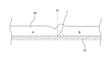
初めに、図1は塗装面を互いに交差しない境界線でA〜Dの各領域に分割した状態を示す図、図2は図1における領域A及び領域Bの境界線付近を示す説明図である。被塗装面2aとしては、例えば、後述する図16に示す自動車のボンネットのような湾曲した表面を有する被塗装物2の表面である。図1に示すように、被塗装面2aは領域Aと、領域Aに隣接する領域Bと、領域Bに隣接する領域Cと、領域Cに隣接する領域Dの4つの領域に分割されている。そして、図2に示すように、T1は領域Aと領域Bの境界線、T1iは領域Aの内側にあって境界線T1と所定の距離L1を隔てて想定される内側境界線(以下、「内側平行線」ともいう。)、T1oは領域Aの外側にあって境界線T1と上記所定の距離を隔てて想定される外側境界線(以下、「外側平行線」ともいう。)である。
[When each area is adjacent by one boundary]
First, FIG. 1 is a diagram showing a state in which a painted surface is divided into areas A to D by boundary lines that do not cross each other, and FIG. 2 is an explanatory diagram showing the vicinity of the boundary lines of areas A and B in FIG. . The surface to be coated 2a is, for example, the surface of the object to be coated 2 having a curved surface such as an automobile bonnet shown in FIG. As shown in FIG. 1, the
まず、領域Aと境界線T1付近をインクジェットプリントヘッド1によって塗装する場合について説明する。図18(a)は領域Aと境界線T1付近における塗膜の厚みの状態を示す説明図である。ここで、所定の均一な厚さの塗膜を得るために必要な単位面積当たりの塗料吐出量をPとしたとき、領域Aにおける内側平行線T1i以内の塗料吐出量はPの100%、境界線T1上における塗料吐出量はPの50%、外側平行線T1oにおける塗料吐出量はPの0%となるように、つまり、内側平行線T1iから外側平行線T1oに向かって徐々に塗料吐出量が減少するような塗膜7が形成されるようにインクジェットプリントヘッド1からの塗料吐出量を制御する。すなわち、境界線T1から距離L1を隔てて想定される仮想的な内側境界線T1iと、境界線T1から距離L1と等距離を隔てて想定される仮想的な外側境界線T1oとの間に存在する点Qの内側境界線T1iからの距離をmとし、所定の厚さの塗膜を形成するために必要な単位面積当たりのインクジェットプリントヘッドからの塗料吐出量をPとした場合、点Qにおける塗料吐出量PQを以下の式に従って算出して塗装を行う。
PQ=P×(2L1−m)/2L1
但し、図18(a)の内側平行線T1iから外側平行線T1oまでの領域において塗料が外側平行線T1o側(図18(a)では右側)に移動(流出)するのを防ぐため、境界線Tから内側平行線T1iまでの距離L1及び境界線T1から外側平行線T1oまでの距離L1はそれぞれ所定の塗膜の厚さの50倍以上の長さとする。
First, a case is described in which painting around 1 region A and the boundary line T by the ink
P Q = P × (2L 1 −m) / 2L 1
However, in order to prevent the paint from moving (outflowing) to the outer parallel line T 1o side (right side in FIG. 18A) in the region from the inner parallel line T 1i to the outer parallel line T 1o in FIG. , respectively the distance L 1 from the distance L 1 and the boundary line T 1 of the to the inner parallel lines T 1i to the outer parallel line T 1o and thickness length of more than 50 times the predetermined coating film from the boundary line T.
例えば、点Qが内側境界線T1i上にある場合には、m=0であるから、塗料吐出量PQは以下のようになる。
PQ=P×(2L1−0)/2L1
=P×2L1/2L1
=P×1
=P
すなわち、Pの100%となる。
For example, when the point Q is on the inner boundary line T 1i , since m = 0, the paint discharge amount P Q is as follows.
P Q = P × (2L 1 −0) / 2L 1
= P × 2L 1 / 2L 1
= Px1
= P
That is, 100% of P.
また、例えば、点Qが境界線T1上にある場合には、m=L1であるから、塗料吐出量PQは以下のようになる。
PQ=P×(2L1−L1)/2L1
=P×L1/2L1
=P×1/2
=0.5P
すなわち、Pの50%となる。
Further, for example, point Q when in top border T 1, since a m = L 1, the paint discharge amount P Q is as follows.
P Q = P × (2L 1 −L 1 ) / 2L 1
= P × L 1 / 2L 1
= P × 1/2
= 0.5P
That is, 50% of P.
同様に、例えば、点Qが外側境界線T1o上にある場合には、m=2L1であるから、塗料吐出量PQは以下のようになる。
PQ=P×(2L1−2L1)/2L1
=P×0/2L1
=P×0/2L1
=0
すなわち、Pの0%となる。
Similarly, for example, when the point Q is on the outer boundary line T 1o , since m = 2L 1 , the paint discharge amount P Q is as follows.
P Q = P × (2L 1 −2L 1 ) / 2L 1
= P × 0 / 2L 1
= P × 0 / 2L 1
= 0
That is, 0% of P.
図18(b)は領域Bと境界線T1付近における塗膜の厚みの状態を示す説明図である。上述した領域Aの場合と同様に、領域Bでは内側平行線T1i(領域Aにおける外側平行線T1oに相当)以内においては塗料吐出量Pの100%、境界線T1においては塗料吐出量Pの50%、外側平行線T1o(領域Aにおける内側平行線T1iに相当)においては塗料吐出量を塗料吐出量Pの0%となるように、つまり、内側平行線T1iから外側平行線T1oに向かって徐々に塗料吐出量が減少するように塗膜8が形成されるようにインクジェットプリントヘッド1からの塗料吐出量を制御する。尚、いうまでもないことであるが、この場合、領域Bにおける外側平行線T1oから内側平行線T1iに向かって徐々に塗料吐出量が増加するようにインクジェットプリントヘッド1からの塗料吐出量を制御しても同じことになる。但し、領域Aの場合と同様に、境界線T1から内側平行線T1iまでの距離L1及び境界線T1から外側平行線T1oまでの距離L1は上記と同様にそれぞれ上記所定の均一な膜厚の50倍以上となるように設定する。
FIG. 18 (b) is an explanatory view showing a state of the coating film thickness in the vicinity of the region B and a boundary line T 1. As in the case of the region A described above, in the region B, the paint discharge amount P is 100% within the inner parallel line T 1i (corresponding to the outer parallel line T 1o in the region A), and the paint discharge amount is at the boundary line T 1 . At 50% of P and the outer parallel line T 1o (corresponding to the inner parallel line T 1i in the region A), the paint discharge amount becomes 0% of the paint discharge amount P, that is, from the inner parallel line T 1i to the outer parallel line. The amount of paint discharged from the
図18(c)は同図(a)及び(b)に示した二つの塗膜を合成して得られた境界線T1付近の塗膜の状態を示す説明図である。図18(c)から明らかなように、合成された塗膜9は境界線T1上においても、領域Aにおける内側平行線T1i及び外側平行線T1oにおいても均一な厚みとなる。尚、境界線T1は直線である必要はなく、図26に示すように曲線であってもよい。このような場合であっても、境界線T1を挟んで内側境界線T1i及び外側境界線T1oは存在し、塗料吐出量Pを上述したように内側境界線T1iから外側境界線T1oに向かって徐々に減少させることにより、図18(c)と同様の均一な膜厚の塗膜を得ることができる。このような塗装方法を領域Aと領域B、領域Bと領域Cと、領域Cと領域Dについてそれぞれ行うことで塗装面2aの全体を均一の厚みの塗膜で塗装することができる。尚、後述する実施例2,3の場合も同様である。
FIG. 18C is an explanatory diagram showing the state of the coating film in the vicinity of the boundary line T 1 obtained by synthesizing the two coating films shown in FIGS. As is apparent from FIG. 18C, the synthesized coating film 9 has a uniform thickness both on the boundary line T 1 and on the inner parallel line T 1i and the outer parallel line T 1o in the region A. Incidentally, the boundary line T 1 need not be a straight line or curve as shown in FIG. 26. Even in such a case, the inner boundary line T 1i and the outer boundary line T 1o are present across the boundary line T 1 , and the paint discharge amount P is changed from the inner boundary line T 1i to the outer
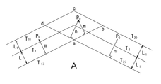
[3つの領域が隣接する場合]
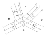
次に、3つの領域が一つの交点(O)を有して互いに隣接する複数領域を均一な厚みで塗膜を形成する塗装方法について説明する。図4は被塗装面を隣接するA〜Cの3つ領域に分割した状態を示す図である。分割された領域Aは領域B,Cと隣接し、領域Bは領域A,Cと隣接し、領域Cは領域A,Bと隣接しており、領域A〜Cがそれぞれ一つの交点(O)を有して互いに隣接した状態となっている。そして、T1は領域Aと領域Bとの境界線、T2は領域Aと領域Cとの境界線、T3は領域Bと領域Cとの境界線である。このように分割された各領域A〜Cをそれぞれインクジェットプリントヘッドによって塗装を行う。
[When three areas are adjacent]
Next, a coating method for forming a coating film with a uniform thickness in a plurality of adjacent areas having three intersections (O) in three areas will be described. FIG. 4 is a diagram showing a state in which the surface to be coated is divided into three areas A to C adjacent to each other. The divided area A is adjacent to the areas B and C, the area B is adjacent to the areas A and C, the area C is adjacent to the areas A and B, and each of the areas A to C has one intersection (O). And are adjacent to each other. T 1 is a boundary line between the region A and the region B, T 2 is a boundary line between the region A and the region C, and T 3 is a boundary line between the region B and the region C. Each of the areas A to C thus divided is painted by an ink jet print head.
(1)[領域Aの塗装]
はじめに、領域Aをインクジェットプリントヘッド1によって塗装する場合について説明する。領域Aの塗装を行う場合には、図5に示すように、領域Aとこれに隣接する領域Bとの間の境界線T1の内側に位置する領域A内に境界線T1から少なくとも塗膜の厚さの50倍以上の長さの距離L1を隔てた位置に仮想的な第1の内側境界線(以下、「内側平行線」ともいう。)T1iを想定する。そして、境界線T1の外側に位置する領域B内に境界線T1から距離L1と等距離を隔てた位置に仮想的な第1の外側境界線(以下、「外側平行線」ともいう。)T1oを想定する。
(1) [Coating of area A]
First, the case where the region A is painted by the
次に、領域Aとこれに隣接する領域Cとの間の境界線T2の内側に位置する領域A内に境界線T2から距離L1を隔てた位置に仮想的な第2の内側境界線T2iを想定する。そして、境界線T2の外側に位置する領域C内に境界線T2から距離L1と等距離を隔てた位置に仮想的な第2の外側境界線T2oを想定する。 Next, a virtual second inner boundary at a position separated from the boundary line T 2 by a distance L 1 in the area A located inside the boundary line T 2 between the area A and the adjacent area C. Assume line T 2i . Then, assuming a hypothetical second outer boundary T 2o from the boundary line T 2 in the region C positioned outside the boundary T 2 at a distance L 1 and equidistant spaced positions.
次に、第1の内側境界線T1iと第1の外側境界線T1o及び第2の内側境界線T2iと第2の外側境界線T2oをそれぞれ延長することによって形成される4つの交点(a,b,c,d)を頂点とする四角形を想定する。そして、被塗装面2a上の任意の点Qが第1の内側境界線T1iと第1の外側境界線T1oとの間に存在する場合における第1の内側境界線T1iからの距離をmとし、任意の点Qが第2の内側境界線T2iと第2の外側境界線T2oとの間に存在する場合における第2の内側境界線T2iからの距離をnとする。そして、所定の厚さの塗膜を形成するために必要な単位面積当たりのインクジェットプリントヘッドからの塗料吐出量をPとした場合、任意の点Qにおける塗料吐出量PQを以下の式に従って算出して塗装を行う。 Next, four intersection points formed by extending the first inner boundary line T 1i and the first outer boundary line T 1o and the second inner boundary line T 2i and the second outer boundary line T 2o respectively. Assume a quadrangle having (a, b, c, d) as vertices. Then, the distance from the first inner boundary line T 1i when an arbitrary point Q on the surface to be coated 2a exists between the first inner boundary line T 1i and the first outer boundary line T 1o is determined. Let m be a distance from the second inner boundary line T 2i when an arbitrary point Q exists between the second inner boundary line T 2i and the second outer boundary line T 2o . Then, calculated according to the case where the paint discharge rate and is P, the following equation paint discharge amount P Q at an arbitrary point Q from the ink jet print head per unit area required to form the predetermined thickness of the coating And paint.
(1−1)任意の点Qが、第1の内側境界線T1iと第2の内側境界線T2iの内側である領域A内に位置する場合
PQ=P
すなわち、所定の厚さの塗膜を形成するために必要な単位面積当たりのインクジェットプリントヘッドからの塗料吐出量Pの100%で塗装を行う。
(1-1) A case where an arbitrary point Q is located in a region A inside the first inner boundary line T 1i and the second inner boundary line T 2i
P Q = P
That is, the coating is performed with 100% of the paint discharge amount P from the ink jet print head per unit area necessary for forming a coating film having a predetermined thickness.
(1−2)任意の点Qが、第1の内側境界線T1iと第1の外側境界線T1oとの間に位置する場合
PQ=P×(2L1−m)/2L1
すなわち、第1の内側境界線T1i上では塗料吐出量Pの100%で塗装を行い、第1の内側境界線T1iから第1の外側境界線T1oに向かって塗料の吐出量を次第に漸減させ、第1の外側境界線T1o上では塗料吐出量Pの0%となるように塗料の吐出量を制御して塗装を行う。
(1-2) When an arbitrary point Q is located between the first inner boundary line T 1i and the first outer boundary line T 1o
P Q = P × (2L 1 −m) / 2L 1
That is, in the first inner border T 1i performs coating with 100% of the paint discharge amount P, gradually the discharge amount of paint from the first inner border T 1i toward the first outer boundary T 1o The coating is performed by gradually decreasing the paint discharge amount so that it becomes 0% of the paint discharge amount P on the first outer boundary T1o .
(1−3)任意の点Qが、第2の内側境界線T2iと第2の外側境界線T2oとの間に位置する場合
PQ=P×(2L1−n)/2L1
すなわち、第2の内側境界線T2i上では塗料吐出量Pの100%で塗装を行い、第2の内側境界線T2iから第2の外側境界線T2oに向かって塗料の吐出量を次第に漸減させ、第2の外側境界線T2o上では塗料吐出量Pの0%となるように塗料の吐出量を制御して塗装を行う。
(1-3) A case where an arbitrary point Q is located between the second inner boundary line T 2i and the second outer boundary line T 2o
P Q = P × (2L 1 −n) / 2L 1
That is, on the second inner border T 2i performs coating with 100% of the paint discharge amount P, gradually the discharge amount of paint from the second inner border T 2i toward the second outer boundary T 2o The coating is performed by gradually decreasing the paint discharge amount so that it becomes 0% of the paint discharge amount P on the second outer boundary line T2o .
(1−4)但し、任意の点Qが、四角形(a,b,c,d)の内側に位置する場合
PQ=P×{(2L1−m)/2L1}×{(2L1−n)/2L1}
すなわち、四角形(a,b,c,d)の範囲内は重複して塗装が行われることになるので均一の厚さの塗膜を形成するためにはその分の吐出量を調整する必要があることに加えて、四角形(a,b,c,d)の範囲内は、後述するように、領域B,Cの塗装を行う場合も同様に重複して塗装が行われるため最終的に被塗装面2aの全体が均一の厚みで塗装されるようにするためにこのような吐出量の調整を行うようにしたものである。
(1-4) However, when an arbitrary point Q is located inside the square (a, b, c, d)
P Q = P × {(2L 1 −m) / 2L 1 } × {(2L 1 −n) / 2L 1 }
That is, since the coating is performed in the range of the square (a, b, c, d), it is necessary to adjust the discharge amount for forming a coating film having a uniform thickness. In addition to the above, within the range of the rectangles (a, b, c, d), as will be described later, when the regions B and C are painted, the coating is performed in the same manner, so that the coverage is finally reached. Such a discharge amount adjustment is performed so that the entire
ここで、領域Aを塗装する場合に、所定の厚さの塗膜を形成するために必要な単位面積当たりのインクジェットプリントヘッドからの塗料吐出量Pを100%とした場合に対する任意の点Q位置における塗料吐出量PQの割合を図6に示す。例えば、任意の点Qが、第1の内側境界線T1iと第1の外側境界線T1oとの間に位置する場合であって、境界線T1上にある場合は以下の通りとなる。
PQ=P×(2L1−L1)/2L1
=100%×1/2
=50%
Here, when the region A is painted, an arbitrary point Q position with respect to the case where the paint discharge amount P from the inkjet print head per unit area necessary for forming a coating film having a predetermined thickness is 100%. Figure 6 shows the percentage of the paint discharge amount P Q in. For example, when an arbitrary point Q is located between the first inner boundary line T 1i and the first outer boundary line T 1o and is on the boundary line T 1 , the following is performed. .
P Q = P × (2L 1 −L 1 ) / 2L 1
= 100% x 1/2
= 50%
また、任意の点Qが、四角形(a,b,c,d)の内側に位置する場合であって、交点Oに位置する場合は以下の通りとなる。
PQ=P×{(2L1−m)/2L1}×{(2L1−n)/2L1}
=100%×(1/2)×(1/2)
=25%
以下、同様にして領域Aを塗装する際の塗料吐出量Pに対する任意の点Qにおける塗料吐出量PQの割合を算出することができる。
Further, when an arbitrary point Q is located inside the quadrangle (a, b, c, d) and is located at the intersection point O, the following occurs.
P Q = P × {(2L 1 −m) / 2L 1 } × {(2L 1 −n) / 2L 1 }
= 100% x (1/2) x (1/2)
= 25%
Hereinafter, it is possible to calculate the percentage of the paint discharge amount P Q in the Q arbitrary point with respect to the paint discharge amount P when painting the area A in the same manner.
(2)[領域Bの塗装]
次に、領域Bをインクジェットプリントヘッド1によって塗装する場合について説明する。領域Bの塗装を行う場合には、図7に示すように、4つの交点(a,b,c,d)を頂点とする四角形の4つの辺のうち、第2の外側境界線T2oによって形成される辺(bc)の中点eを通り且つ領域Bと領域Cとの間の境界線T3に平行な仮境界線T3’を想定する。また、第2の外側境界線T2oと第1の内側境界線T1iとの交点bを通って仮境界線T3’と平行な第3の内側境界線T3’iを想定すると共に、第2の外側境界線T2oと第1の外側境界線T1oとの交点cを通って仮境界線T3’と平行な第3の外側境界線T3’oを想定する。そして、第3の内側境界線T3’iと仮境界線T3’との間の距離及び第3の外側境界線T3’oと仮境界線T3’との間の距離をそれぞれL2とする。そして、点Qが第3の内側境界線T3’iと第3の外側境界線T3’oとの間に存在する場合における第3の内側境界線T3’iからの距離をsとする。そして、所定の厚さの塗膜を形成するために必要な単位面積当たりのインクジェットプリントヘッドからの塗料吐出量をPとした場合、任意の点Qにおける塗料吐出量PQを以下の式に従って算出して塗装を行う。
(2) [Coating of area B]
Next, a case where the region B is painted with the
(2−1)任意の点Qが、第1の外側境界線T1oと第3の外側境界線T3’oの内側である領域B内に位置する場合
PQ=P
すなわち、所定の厚さの塗膜を形成するために必要な単位面積当たりのインクジェットプリントヘッドからの塗料吐出量Pの100%で塗装を行う。
(2-1) A case where an arbitrary point Q is located in a region B that is inside the first outer boundary line T 1o and the third outer boundary line T 3′o
P Q = P
That is, the coating is performed with 100% of the paint discharge amount P from the ink jet print head per unit area necessary for forming a coating film having a predetermined thickness.
(2−2)任意の点Qが、第1の外側境界線T1oと第1の内側境界線T1iとの間に位置する場合
PQ=P×m/2L1
すなわち、第1の外側境界線T1o上では塗料吐出量Pの100%で塗装を行い、第1の外側境界線T1oから第1の内側境界線T1iに向かって塗料の吐出量を次第に漸減させ、第1の内側境界線T1i上では塗料吐出量Pの0%となるように塗料の吐出量を制御して塗装を行う。
(2-2) When an arbitrary point Q is located between the first outer boundary line T 1o and the first inner boundary line T 1i
P Q = P × m / 2L 1
That is, in the first outer boundary T 1o performed painted with 100% of the paint discharge amount P, gradually the discharge amount of paint from the first outer boundary T 1o towards the first inner borderline T 1i The coating is performed by gradually decreasing the paint discharge amount to be 0% of the paint discharge amount P on the first inner boundary line T 1i .
(2−3)任意の点Qが、第3の外側境界線T3’oと第3の内側境界線T3’iとの間に位置する場合
PQ=P×s/2L2
すなわち、第3の外側境界線T3’o上では塗料吐出量Pの100%で塗装を行い、第3の外側境界線T3’oから第3の内側境界線T3’iに向かって塗料の吐出量を次第に漸減させ、第3の内側境界線T3’i上では塗料吐出量Pの0%となるように塗料の吐出量を制御して塗装を行う。
(2-3) When an arbitrary point Q is located between the third outer boundary line T 3′o and the third inner boundary line T 3′i
P Q = P × s / 2L 2
That is, in the third outer boundary T 3'O performed painted with 100% of the paint discharge amount P, the third outer boundary T 3'O toward the third inner border T 3'I The paint discharge amount is gradually decreased, and coating is performed by controlling the paint discharge amount to be 0% of the paint discharge amount P on the third inner boundary T 3′i .
(2−4)任意の点Qが、四角形(a,b,c,d)の内側に位置する場合
PQ=P×m/2L1
すなわち、四角形(a,b,c,d)の範囲内は、述したように、終的に被塗装面2aの全体が均一の厚みで塗装されるようにするためにこのような吐出量の調整を行う。
(2-4) When an arbitrary point Q is located inside a quadrilateral (a, b, c, d)
P Q = P × m / 2L 1
That is, within the range of the quadrangle (a, b, c, d), as described above, in order to finally coat the
ここで、領域Bを塗装する場合に、所定の厚さの塗膜を形成するために必要な単位面積当たりのインクジェットプリントヘッドからの塗料吐出量Pを100%とした場合に対する任意の点Q位置における塗料吐出量PQの割合を図8に示す。例えば、任意の点Qが、第1の外側境界線T1oと第1の内側境界線T1iとの間に位置する場合であって、境界線T1上にある場合は以下の通りとなる。
PQ=P×m/2L1
=100%×(1/2)
=50%
Here, when the region B is applied, an arbitrary point Q position with respect to the case where the paint discharge amount P from the ink jet print head per unit area necessary for forming a coating film having a predetermined thickness is 100%. Figure 8 shows the percentage of the paint discharge amount P Q in. For example, when an arbitrary point Q is located between the first outer boundary line T 1o and the first inner boundary line T 1i and is on the boundary line T 1 , the following is performed. .
P Q = P × m / 2L 1
= 100% x (1/2)
= 50%
また、任意の点Qが、第3の外側境界線T3’oと第3の内側境界線T3’iとの間に位置する場合であって、仮境界線T3’上にある場合は以下の通りとなる。
PQ=P×s/2L2
=100%×(1/2)
=50%
In addition, when an arbitrary point Q is located between the third outer boundary line T 3′o and the third inner boundary line T 3′i and is on the temporary boundary line T 3 ′ Is as follows.
P Q = P × s / 2L 2
= 100% x (1/2)
= 50%
また、任意の点Qが、四角形(a,b,c,d)の内側に位置する場合であって、交点Oに位置する場合は以下の通りとなる。
PQ=P×m/2L1
=100%×(1/2)
=50%
以下、同様にして領域Bを塗装する際の塗料吐出量Pに対する任意の点Qにおける塗料吐出量PQの割合を算出することができる。
Further, when an arbitrary point Q is located inside the quadrangle (a, b, c, d) and is located at the intersection point O, the following occurs.
P Q = P × m / 2L 1
= 100% x (1/2)
= 50%
Hereinafter, it is possible to calculate the percentage of the paint discharge amount P Q in the Q arbitrary point with respect to the paint discharge amount P when painting the region B in the same manner.
(3)[領域Cの塗装]
次に、領域Cをインクジェットプリントヘッド1によって塗装する場合について図9を参照しつつ説明する。
(3) [Coating of area C]
Next, a case where the region C is painted by the ink
(3−1)任意の点Qが、第2の外側境界線T2oと第3の内側境界線T3’iの内側である領域C内に位置する場合
PQ=P
すなわち、所定の厚さの塗膜を形成するために必要な単位面積当たりのインクジェットプリントヘッドからの塗料吐出量Pの100%で塗装を行う。
(3-1) A case where an arbitrary point Q is located in a region C that is inside the second outer boundary line T 2o and the third inner boundary line T 3′i.
P Q = P
That is, the coating is performed with 100% of the paint discharge amount P from the ink jet print head per unit area necessary for forming a coating film having a predetermined thickness.
(3−2)任意の点Qが、第2の外側境界線T2oと第2の内側境界線T2iとの間に位置する場合
PQ=P×n/2L1
すなわち、第2の外側境界線T2o上では塗料吐出量Pの100%で塗装を行い、第2の外側境界線T2oから第2の内側境界線T2iに向かって塗料の吐出量を次第に漸減させ、第2の内側境界線T2i上では塗料吐出量Pの0%となるように塗料の吐出量を制御して塗装を行う。
(3-2) When an arbitrary point Q is located between the second outer boundary line T 2o and the second inner boundary line T 2i
P Q = P × n / 2L 1
That is, on the second outer boundary T 2o perform painting at 100% of the paint discharge amount P, gradually the discharge amount of paint from the second outer boundary T 2o toward the second inner border T 2i The coating is performed by gradually decreasing the paint discharge amount so as to be 0% of the paint discharge amount P on the second inner boundary line T2i .
(3−3)任意の点Qが、第3の内側境界線T3’iと第3の外側境界線T3’oとの間に位置する場合
PQ=P×(2L2−s)/2L2
すなわち、第3の内側境界線T3’i上では塗料吐出量Pの100%で塗装を行い、第3の内側境界線T3’iから第3の外側境界線T3’oに向かって塗料の吐出量を次第に漸減させ、第3の外側境界線T3’o上では塗料吐出量Pの0%となるように塗料の吐出量を制御して塗装を行う。
(3-3) When an arbitrary point Q is located between the third inner boundary line T 3′i and the third outer boundary line T 3′o
P Q = P × (2L 2 −s) / 2L 2
That is, in the third inner border T 3'I performed painted with 100% of the paint discharge amount P, the third inner border T 3'I toward the third outer boundary T 3'O The paint discharge amount is gradually decreased, and coating is performed by controlling the paint discharge amount to be 0% of the paint discharge amount P on the third outer boundary line T 3′o .
任意の点Qが、前記四角形(a,b,c,d)の内側に位置する場合
PQ=P×{(2L1−m)/2L1}×(n/2L1)
すなわち、四角形(a,b,c,d)の範囲内は、述したように、終的に被塗装面2aの全体が均一の厚みで塗装されるようにするためにこのような吐出量の調整を行う。
When an arbitrary point Q is located inside the square (a, b, c, d)
P Q = P × {(2L 1 −m) / 2L 1 } × (n / 2L 1 )
That is, within the range of the quadrangle (a, b, c, d), as described above, in order to finally coat the
ここで、領域Cを塗装する場合に、所定の厚さの塗膜を形成するために必要な単位面積当たりのインクジェットプリントヘッドからの塗料吐出量Pを100%とした場合に対する任意の点Q位置における塗料吐出量PQの割合を図10に示す。例えば、任意の点Qが第2の外側境界線T2oと第2の内側境界線T2iとの間に位置する場合であって、境界線T2上にある場合は以下の通りとなる。
PQ=P×n/2L1
=100%×(1/2)
=50%
Here, when the region C is applied, an arbitrary point Q position with respect to the case where the paint discharge amount P from the ink jet print head per unit area necessary for forming a coating film having a predetermined thickness is 100%. Figure 10 shows the percentage of the paint discharge amount P Q in. For example, when an arbitrary point Q is located between the second outer boundary line T 2o and the second inner boundary line T 2i and is on the boundary line T 2 , the following is performed.
P Q = P × n / 2L 1
= 100% x (1/2)
= 50%
また、任意の点Qが、四角形(a,b,c,d)の内側に位置する場合であって、交点Oに位置する場合は以下の通りとなる。
PQ=P×{(2L1−m)/2L1}×(n/2L1)
=100%×(1/2)×(1/2)
=25%
Further, when an arbitrary point Q is located inside the quadrangle (a, b, c, d) and is located at the intersection point O, the following occurs.
P Q = P × {(2L 1 −m) / 2L 1 } × (n / 2L 1 )
= 100% x (1/2) x (1/2)
= 25%
以下、同様にして領域Cを塗装する際の塗料吐出量Pに対する任意の点Qにおける塗料吐出量PQの割合を算出することができる。ここで、上述のように領域A〜Cをそれぞれ塗装した場合の交点Oにおける塗料吐出量PQは、領域Aの塗装において塗料吐出量Pの25%であり、領域Bの塗装において塗料吐出量Pの50%であり、領域Cの塗装において塗料吐出量Pの25%となり、合計で100%、所定の厚さの塗膜を形成するために必要な単位面積当たりのインクジェットプリントヘッドからの塗料吐出量Pが塗布されることになる。尚、図4では境界線T1,T2,T3はそれぞれ90°ではない角度で接しているが、例えば図11に示すように、境界線T1と境界線T3が同一直線状にあり、境界線T2がそれと直交するように接するような場合であっても同様である。
Hereinafter, it is possible to calculate the percentage of the paint discharge amount P Q in the Q arbitrary point with respect to the paint discharge amount P when painting the area C in the same manner. Here, the paint discharge amount P Q at the intersection O of when painted each region A~C as described above, 25% of the paint discharge amount P in the coating region A, the paint discharge amount in the
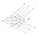
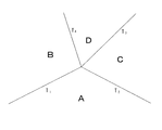
[4つの領域が隣接する場合]
次に、4つの領域が一つの交点(O)を有して互いに隣接する複数領域を均一な厚みで塗膜を形成する塗装方法について説明する。図12は、被塗装面を隣接するA〜Dの4つ領域に分割した状態を示す図である。分割された領域Aは領域B,Cと隣接し、領域Bは領域A,Dと隣接し、領域Cは領域A,Cと隣接し、領域Dは領域B,Cと隣接ており、領域A〜Dがそれぞれ一つの交点(O)を有して互いに隣接した状態となっている。そして、T1は領域Aと領域Bとの境界線、T2は領域Aと領域Cとの境界線、T3は領域Cと領域Dとの境界線、T4は領域Bと領域Dとの境界線である。このように分割された各領域A〜Dをそれぞれインクジェットプリントヘッドによって塗装を行う。
[When four areas are adjacent]
Next, a coating method for forming a coating film with a uniform thickness on a plurality of adjacent regions having four intersections (O) in four regions will be described. FIG. 12 is a diagram showing a state in which the surface to be coated is divided into four areas A to D adjacent to each other. The divided region A is adjacent to the regions B and C, the region B is adjacent to the regions A and D, the region C is adjacent to the regions A and C, the region D is adjacent to the regions B and C, and the region A ˜D each have one intersection (O) and are adjacent to each other. T 1 is a boundary line between the region A and the region B, T 2 is a boundary line between the region A and the region C, T 3 is a boundary line between the region C and the region D, and T 4 is a boundary line between the region B and the region D. Is the boundary line. Each of the areas A to D thus divided is painted by an ink jet print head.
はじめに、上述した3の領域が隣接する場合と同様に、A〜Dの4つの領域のうちの領域Aとこれに隣接する領域Bとの間の境界線T1の内側に位置する領域A内に境界線T1から少なくとも塗膜の厚さの50倍以上の長さの距離L1を隔てた位置に仮想的な第1の内側境界線T1iを想定する。また、第1の境界線T1の外側に位置する領域B内に境界線T1から距離L1と等距離を隔てた位置に仮想的な第1の外側境界線T1oを想定する。 First , as in the case where the three regions described above are adjacent to each other, in the region A located inside the boundary line T1 between the region A of the four regions A to D and the region B adjacent thereto, A virtual first inner boundary line T 1i is assumed at a position separated from the boundary line T 1 by a distance L 1 that is at least 50 times as long as the thickness of the coating film. Further, assume a virtual first outer boundary T 1o from the boundary line T 1 in the region B which is located outside the first borderline T 1 at a distance L 1 and equidistant spaced positions.
次に、領域Aとこれに隣接する領域Cとの間の境界線T2の内側に位置する領域A内に境界線T2から距離L1を隔てた位置に仮想的な第2の内側境界線T2iを想定する。そして、第2の境界線T2の外側に位置する領域C内に境界線T2から距離L1と等距離を隔てた位置に仮想的な第2の外側境界線T2oを想定する。 Next, a virtual second inner boundary at a position separated from the boundary line T 2 by a distance L 1 in the area A located inside the boundary line T 2 between the area A and the adjacent area C. Assume line T 2i . Then, assuming a hypothetical second outer boundary T 2o from the boundary line T 2 in the region C positioned on the outer side of the second boundary line T 2 at a distance L 1 and equidistant spaced positions.
次に、第1の内側境界線T1iと第1の外側境界線T1o及び第2の内側境界線T2iと第2の外側境界線T2oをそれぞれ延長することによって形成される4つの交点(a,b,c,d)を頂点とする四角形の4つの辺のうち、第2の外側境界線T2oによって形成される辺(bc)の中点eを通り且つ領域Cと領域Dとの間の境界線T3に平行な仮境界線T3’を想定する。さらに、第2の外側境界線T2oと第1の内側境界線T1iとの交点bを通って仮境界線T3’と平行な第3の内側境界線T3’iを想定すると共に、第2の外側境界線T2oと第1の外側境界線T1oとの交点cを通って仮境界線T3’と平行な第3の外側境界線T3’oを想定する。そして、第3の内側境界線T3’iと仮境界線T3’との間の距離及び第3の外側境界線T3’oと仮境界線T3’との間の距離をそれぞれL2とする。 Next, four intersection points formed by extending the first inner boundary line T 1i and the first outer boundary line T 1o and the second inner boundary line T 2i and the second outer boundary line T 2o respectively. Among the four sides of the quadrangle having (a, b, c, d) as vertices, the region C and the region D pass through the midpoint e of the side (bc) formed by the second outer boundary line T 2o . assume a parallel temporary boundary T 3 'to the boundary line T 3 between. Furthermore, assuming a third inner boundary line T 3′i parallel to the temporary boundary line T 3 ′ through the intersection b of the second outer boundary line T 2o and the first inner boundary line T 1i , Assume a third outer boundary line T 3′o parallel to the temporary boundary line T 3 ′ through the intersection point c between the second outer boundary line T 2o and the first outer boundary line T 1o . The distance between the third inner boundary line T 3′i and the temporary boundary line T 3 ′ and the distance between the third outer boundary line T 3′o and the temporary boundary line T 3 ′ are expressed as L 2 .
次に、四角形(a,b,c,d)の4つの辺のうち、第1の外側境界線T1oによって形成される辺(cd)の中点fを通り且つ領域Bと領域Dとの間の境界線T4に平行な仮境界線T4’を想定する。さらに第1の外側境界線T1oと第2の外側境界線T2oとの交点cを通って仮境界線T4’と平行な第4の内側境界線T4’iを想定すると共に、第1の外側境界線T1oと第2の内側境界線T2iとの交点dを通って仮境界線T4’と平行な第4の外側境界線T4’oを想定する。そして、第4の内側境界線T4’iと仮境界線T4’との間の距離及び第4の外側境界線T4’oとの間の距離をそれぞれL3とする。 Next, among the four sides of the quadrangle (a, b, c, d), it passes through the midpoint f of the side (cd) formed by the first outer boundary line T 1o , and the region B and the region D assume a temporary boundary T 4 'parallel to the boundary line T 4 between. Furthermore, a fourth inner boundary line T 4′i parallel to the temporary boundary line T 4 ′ through the intersection c between the first outer boundary line T 1o and the second outer boundary line T 2o is assumed, and the first Assume a fourth outer boundary line T 4′o that is parallel to the temporary boundary line T 4 ′ through the intersection d of the first outer boundary line T 1o and the second inner boundary line T 2i . The distance between the fourth inner boundary line T 4′i and the temporary boundary line T 4 ′ and the distance between the fourth outer boundary line T 4′o are set to L 3 .
そして、被塗装面上の任意の点Qが第1の内側境界線T1iと第1の外側境界線T1oとの間に存在する場合における第1の内側境界線T1iからの距離をmとし、任意の点Qが第2の内側境界線T2iと第2の外側境界線T2oとの間に存在する場合における第2の内側境界線T2iからの距離をnとし、点Qが第3の内側境界線T3’iと第3の外側境界線T3’oとの間に存在する場合における第3の内側境界線T3’iからの距離をsとし、点Qが第4の内側境界線T4’iと第4の外側境界線T4’oとの間に存在する場合における第4の内側境界線T4’iからの距離をtとする。そして、所定の厚さの塗膜を形成するために必要な単位面積当たりのインクジェットプリントヘッドからの塗料吐出量をPとした場合、領域A〜Dの塗装は、それぞれ任意の点Qにおける塗料吐出量PQを以下の式に従って算出して塗装を行う。 The distance from the first inner boundary line T 1i when the arbitrary point Q on the surface to be coated exists between the first inner boundary line T 1i and the first outer boundary line T 1o is expressed as m. And the distance from the second inner boundary line T 2i when an arbitrary point Q exists between the second inner boundary line T 2i and the second outer boundary line T 2o is n, and the point Q is The distance from the third inner boundary line T 3′i when it exists between the third inner boundary line T 3′i and the third outer boundary line T 3′o is s, and the point Q is Let t be the distance from the fourth inner boundary line T 4′i when it exists between the fourth inner boundary line T 4′i and the fourth outer boundary line T 4′o . Then, assuming that the amount of paint discharged from the inkjet print head per unit area necessary for forming a coating film having a predetermined thickness is P, the coating of the areas A to D is performed at any point Q. The amount PQ is calculated according to the following formula to perform coating.
(1)[領域A及び領域Cの塗装]
領域Aと領域Cの塗装については上述した実施例2である3つの領域が隣接する場合と同様である事からその説明を省略する。
(1) [Coating of area A and area C]
Since the coating of the region A and the region C is the same as that in the case where the three regions in the second embodiment are adjacent to each other, the description thereof is omitted.
(2)[領域Bの塗装]
次に、領域Bをインクジェットプリントヘッド1によって塗装する場合について説明する。領域Bの塗装を行う場合には、図13に示すように、4つの交点(a,b,c,d)を頂点とする四角形の4つの辺のうち、第1の外側境界線T1oによって形成される辺(cd)の中点fを通り且つ領域Bと領域Dとの間の境界線T4に平行な仮境界線T4’を想定する。また、第1の外側境界線T1oと第2の外側境界線T2oとの交点cを通って仮境界線T4’と平行な第4の内側境界線T4’iを想定すると共に、第1の外側境界線T1oと第2の内側境界線T2iとの交点dを通って仮境界線T4’と平行な第4の外側境界線T4’oを想定する。そして、第4の内側境界線T4’iと仮境界線T4’との間の距離及び第4の外側境界線T4’oとの間の距離をそれぞれL3とする。そして、任意の点Qが第4の内側境界線T4’iと第4の外側境界線T4’oとの間に存在する場合における第4の内側境界線T4’iからの距離をtとする。そして、所定の厚さの塗膜を形成するために必要な単位面積当たりのインクジェットプリントヘッドからの塗料吐出量をPとした場合、任意の点Qにおける塗料吐出量PQを以下の式に従って算出して塗装を行う。
(2) [Coating of area B]
Next, a case where the region B is painted with the
(2−1)任意の点Qが、第1の外側境界線T1oと第4の外側境界線T4’oの内側の領域B内に位置する場合
PQ=P
すなわち、所定の厚さの塗膜を形成するために必要な単位面積当たりのインクジェットプリントヘッドからの塗料吐出量Pの100%で塗装を行う。
(2-1) A case where an arbitrary point Q is located in a region B inside the first outer boundary line T 1o and the fourth outer boundary line T 4′o
P Q = P
That is, the coating is performed with 100% of the paint discharge amount P from the ink jet print head per unit area necessary for forming a coating film having a predetermined thickness.
(2−2)任意の点Qが、第1の外側境界線T1oと第1の内側境界線T1iとの間に位置する場合
PQ=P×m/2L1
すなわち、第1の外側境界線T1o上では塗料吐出量Pの100%で塗装を行い、第1の外側境界線T1oから第1の内側境界線T1iに向かって塗料の吐出量を次第に漸減させ、第1の内側境界線T1i上では塗料吐出量Pの0%となるように塗料の吐出量を制御して塗装を行う。
(2-2) When an arbitrary point Q is located between the first outer boundary line T 1o and the first inner boundary line T 1i
P Q = P × m / 2L 1
That is, in the first outer boundary T 1o performed painted with 100% of the paint discharge amount P, gradually the discharge amount of paint from the first outer boundary T 1o towards the first inner borderline T 1i The coating is performed by gradually decreasing the paint discharge amount to be 0% of the paint discharge amount P on the first inner boundary line T 1i .
(2−3)任意の点Qが、第4の外側境界線T4’oと第4の内側境界線T4’iとの間に位置する場合
PQ=P×t/2L3
すなわち、第4の外側境界線T4’o上では塗料吐出量Pの100%で塗装を行い、第4の外側境界線T4’oから第4の内側境界線T4’iに向かって塗料の吐出量を次第に漸減させ、第4の内側境界線T4’i上では塗料吐出量Pの0%となるように塗料の吐出量を制御して塗装を行う。
(2-3) A case where an arbitrary point Q is located between the fourth outer boundary line T 4′o and the fourth inner boundary line T 4′i.
P Q = P × t / 2L 3
That is, in the fourth outer boundary T 4'O performed painted with 100% of the paint discharge amount P, the fourth outer boundary T 4'O toward the fourth inner border T 4'I The paint discharge amount is gradually decreased, and coating is performed by controlling the paint discharge amount to be 0% of the paint discharge amount P on the fourth inner boundary line T 4′i .
(2−4)任意の点Qが、四角形(a,b,c,d)の内側に位置する場合
PQ=P×{(2L1−n)/2L1}×(m/2L1)
すなわち、四角形(a,b,c,d)の範囲内は、述したように、最終的に被塗装面2aの全体が均一の厚みで塗装されるようにするためにこのような吐出量の調整を行う。
(2-4) When an arbitrary point Q is located inside a quadrilateral (a, b, c, d)
P Q = P × {(2L 1 −n) / 2L 1 } × (m / 2L 1 )
That is, within the range of the quadrangle (a, b, c, d), as described above, in order to finally coat the
ここで、領域Bを塗装する場合に、所定の厚さの塗膜を形成するために必要な単位面積当たりのインクジェットプリントヘッドからの塗料吐出量Pを100%とした場合に対する任意の点Q位置における塗料吐出量PQの割合を図14に示す。例えば、任意の点Qが第4の外側境界線T4’oと第4の内側境界線T4’iとの間に位置する場合であって、境界線T4’上にある場合は以下の通りとなる。
PQ=P×t/2L3
=100%×(1/2)
=50%
Here, when the region B is applied, an arbitrary point Q position with respect to the case where the paint discharge amount P from the ink jet print head per unit area necessary for forming a coating film having a predetermined thickness is 100%. 14 the proportion of the paint discharge amount P Q in. For example, when an arbitrary point Q is located between the fourth outer boundary line T 4′o and the fourth inner boundary line T 4′i and is on the boundary line T 4 ′ , It becomes as follows.
P Q = P × t / 2L 3
= 100% x (1/2)
= 50%
また、任意の点Qが、四角形(a,b,c,d)の内側に位置する場合であって、交点Oに位置する場合は以下の通りとなる。
PQ=P×{(2L1−n)/2L1}×(m/2L1)
=100%×(1/2)×(1/2)
=25%
以下、同様にして領域Bを塗装する際の塗料吐出量Pに対する任意の点Qにおける塗料吐出量PQの割合を算出することができる。
Further, when an arbitrary point Q is located inside the quadrangle (a, b, c, d) and is located at the intersection point O, the following occurs.
P Q = P × {(2L 1 −n) / 2L 1 } × (m / 2L 1 )
= 100% x (1/2) x (1/2)
= 25%
Hereinafter, it is possible to calculate the percentage of the paint discharge amount P Q in the Q arbitrary point with respect to the paint discharge amount P when painting the region B in the same manner.
(3)[領域Dの塗装]
次に、領域Dをインクジェットプリントヘッド1によって塗装する場合について図13を参照しつつ説明する。
(3) [Coating of area D]
Next, a case where the region D is painted by the
(3−1)任意の点Qが、第3の外側境界線T3’oと第4の内側境界線T4’iの内側の領域D内に位置する場合
PQ=P
すなわち、所定の厚さの塗膜を形成するために必要な単位面積当たりのインクジェットプリントヘッドからの塗料吐出量Pの100%で塗装を行う。
(3-1) A case where an arbitrary point Q is located in a region D inside the third outer boundary line T 3′o and the fourth inner boundary line T 4′i.
P Q = P
That is, the coating is performed with 100% of the paint discharge amount P from the ink jet print head per unit area necessary for forming a coating film having a predetermined thickness.
(3−2)任意の点Qが、第3の外側境界線T3’oと第3の内側境界線T3’iとの間に位置する場合
PQ=P×s/2L2
すなわち、第3の外側境界線T3’o上では塗料吐出量Pの100%で塗装を行い、第3の外側境界線T3’oから第3の内側境界線T3’iに向かって塗料の吐出量を次第に漸減させ、第3の内側境界線T3’i上では塗料吐出量Pの0%となるように塗料の吐出量を制御して塗装を行う。
(3-2) When an arbitrary point Q is located between the third outer boundary line T 3′o and the third inner boundary line T 3′i
P Q = P × s / 2L 2
That is, in the third outer boundary T 3'O performed painted with 100% of the paint discharge amount P, the third outer boundary T 3'O toward the third inner border T 3'I The paint discharge amount is gradually decreased, and coating is performed by controlling the paint discharge amount to be 0% of the paint discharge amount P on the third inner boundary T 3′i .
(3−3)任意の点Qが、第4の内側境界線T4’iと第4の外側境界線T4’oとの間に位置する場合
PQ=P×(2L3−t)/2L3
すなわち、第4の内側境界線T4’i上では塗料吐出量Pの100%で塗装を行い、第4の内側境界線T4’iから第4の外側境界線T4’oに向かって塗料の吐出量を次第に漸減させ、第4の外側境界線T4’o上では塗料吐出量Pの0%となるように塗料の吐出量を制御して塗装を行う。
(3-3) A case where an arbitrary point Q is located between the fourth inner boundary line T 4′i and the fourth outer boundary line T 4′o
P Q = P × (2L 3 −t) / 2L 3
That is, in the fourth inner border T 4'I performed painted with 100% of the paint discharge amount P, the fourth inner border T 4'I toward the fourth outer boundary T 4'O The paint discharge amount is gradually decreased, and coating is performed by controlling the paint discharge amount to be 0% of the paint discharge amount P on the fourth outer boundary line T4′o .
(3−4)任意の点Qが、四角形(a,b,c,d)の内側に位置する場合
PQ=P×(m/2L1)×(n/2L1)
すなわち、四角形(a,b,c,d)の範囲内は、述したように、終的に被塗装面2aの全体が均一の厚みで塗装されるようにするためにこのような吐出量の調整を行う。
(3-4) A case where an arbitrary point Q is located inside a square (a, b, c, d)
P Q = P × (m / 2L 1 ) × (n / 2L 1 )
That is, within the range of the quadrangle (a, b, c, d), as described above, in order to finally coat the
ここで、領域Dを塗装する場合に、所定の厚さの塗膜を形成するために必要な単位面積当たりのインクジェットプリントヘッドからの塗料吐出量Pを100%とした場合に対する任意の点Q位置における塗料吐出量PQの割合を図15に示す。例えば、任意の点Qが第4の内側境界線T4’iと第4の外側境界線T4’oとの間に位置する場合であって、境界線T4’上にある場合は以下の通りとなる。
PQ=P×(2L3−t)/2L3
=100%×(1/2)
=50%
Here, when the region D is painted, an arbitrary point Q position with respect to the case where the paint discharge amount P from the ink jet print head per unit area necessary for forming a coating film having a predetermined thickness is 100%. FIG. 15 shows the percentage of the paint discharge amount P Q in. For example, when an arbitrary point Q is located between the fourth inner boundary line T 4′i and the fourth outer boundary line T 4′o and is on the boundary line T 4 ′ , It becomes as follows.
P Q = P × (2L 3 −t) / 2L 3
= 100% x (1/2)
= 50%
また、任意の点Qが、四角形(a,b,c,d)の内側に位置する場合であって、交点Oに位置する場合は以下の通りとなる。
PQ=P×(m/2L1)×(n/2L1)
=100%×(1/2)×(1/2)
=25%
Further, when an arbitrary point Q is located inside the quadrangle (a, b, c, d) and is located at the intersection point O, the following occurs.
P Q = P × (m / 2L 1 ) × (n / 2L 1 )
= 100% x (1/2) x (1/2)
= 25%
ここで、上述のように領域A〜Dをそれぞれ塗装した場合の交点Oにおける塗料吐出量PQは、領域Aの塗装において塗料吐出量Pの25%であり、領域Bの塗装において塗料吐出量Pの25%であり、領域Cの塗装において塗料吐出量Pの25%であり、領域Dの塗装において塗料吐出量Pの25%となり、合計で100%、所定の厚さの塗膜を形成するために必要な単位面積当たりのインクジェットプリントヘッドからの塗料吐出量Pが塗布されることになる。尚、図12では境界線T1,T2,T3,T4は、それぞれ90°ではない角度で接しているが、境界線T1と境界線T3が同一直線状にあり、境界線T2と境界線T4が同一直線状にあり、境界線T1,T3が境界線T2,T4と直交するように接するような場合であっても同様である。また、境界線が5つ以上の場合であっても、四角形(a,b,c,d)の4つの辺のうち、境界線が交差する辺の基点となる交点を利用してその境界線と平行な仮境界線を設定することにより上記と同様に吐出料を算出することができる。
Here, the paint discharge amount P Q at the intersection O of when painted each region A~D as described above, 25% of the paint discharge amount P in the coating region A, the paint discharge amount in the
尚、境界線T1,T2,T3は直線である必要はなく、曲線であってもよい。このような場合であっても、例えば図26に示すように、境界線T1を挟んで内側境界線T1i及び外側境界線T1oは存在し、塗料吐出量Pを上述したように内側境界線T1iから外側境界線T1oに向かって徐々に減少させることにより、図18(c)と同様の均一な膜厚の塗膜を得ることができる。このような塗装方法を領域Aと領域B,C、領域Bと領域A,C、領域Cと領域A,Bについてそれぞれ行うことで塗装面2aの全体を均一の厚みの塗膜で塗装することができる。
The boundary lines T 1 , T 2 , T 3 do not have to be straight lines, but may be curved lines. Even in such a case, for example, as shown in FIG. 26, the inner boundary line T 1i and the outer boundary line T 1o exist with the boundary line T 1 in between, and the paint discharge amount P is set to the inner boundary line as described above. By gradually decreasing from the line T 1i toward the outer boundary line T 1o , a coating film having a uniform film thickness similar to that in FIG. 18C can be obtained. By applying such a coating method for region A and regions B and C, region B and regions A and C, and region C and regions A and B, respectively, the entire painted
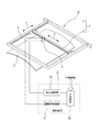
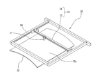
[インクジェットプリント装置の構成]
次に、本発明に係る隣接する複数領域を均一な厚みで塗膜を形成する塗装方法を実施するための好ましいインクジェットプリント装置について説明する。図19は本発明に係る塗装方法を実施するためインクジェットプリント装置の一実施形態を示す構成図である。図示されたインクジェットプリント装置10は、概略として、インクジェットプリントヘッド1と、図示しない駆動用モータによってインクジェットプリントヘッド1をX軸方向へ往復動させるX軸移動機構3と、図示しない駆動用モータによってインクジェットプリントヘッド1をY軸方向へ往復動させるY軸移動機構4と、X軸移動機構3及びY軸移動機構4の図示しない駆動用モータの制御及びインクジェットプリントヘッド1の塗料の吐出を制御する制御装置5を備えて構成されている。X軸移動機構3とY軸移動機構4とによってX−Yテーブル6が構成され、このX−Yテーブル6にインクジェットプリントヘッド1が取り付けられている。そして、制御装置5に予め保存されているプログラムに従ってX軸移動機構3及びY軸移動機構4を制御することによりインクジェットプリントヘッド1の吐出が制御され、その複数のノズルから被塗装物2に向けて塗料が吐出されて塗装が行われる。また、X−Yテーブル6の下方には被塗装物2を載置する図示しない載置台が配置されており、この載置台は被塗装物2の被塗装面を複数の領域に分割した各領域をインクジェットプリントヘッド1からの距離を近接させることができるように被塗装物2の保持位置を変えることができるようになっている。
[Configuration of inkjet printing apparatus]
Next, a preferred inkjet printing apparatus for carrying out a coating method for forming a coating film with a uniform thickness on a plurality of adjacent areas according to the present invention will be described. FIG. 19 is a block diagram showing an embodiment of an inkjet printing apparatus for carrying out the coating method according to the present invention. The illustrated
制御装置5は、実施例1〜3において示した各式に従って塗料吐出量PQを制御する制御プログラム、塗装情報、データ等を格納するメモリ及びCPU(いずれも図示せず)等を備えた主制御装置50と、主制御装置50の制御に基づいてX軸移動機構3及びY軸移動機構4の各駆動モータを制御する駆動系制御装置51と、主制御装置50の制御に基づいてインクジェットプリントヘッド1の各色のノズル毎に設けられた圧電素子等(図示せず)を駆動して塗料の吐出を制御する吐出制御装置52を備えて構成されている。また、図示しない載置台を適宜に可動することによって被塗装物2の保持位置を変える制御も行う。
The
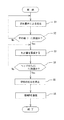
[制御例]
次に、インクジェットプリント装置10の塗装制御について図3及び図17を参照して説明する。図3は実施例1の塗装方法の一実施形態のフローチャート、図17は実施例2の塗装方法の一実施形態を示すフローチャートである。初めに、実施例1の場合について説明する。被塗装物2の被塗装面2aを図1に示すように複数の領域に分割して塗装を行う場合、予め駆動部5の主制御装置50に上述した点Qにおける塗料吐出量PQを算出するための式に基づく塗料吐出量の制御プログラム、例えば領域A〜Dと各境界線T1、塗装の膜厚、塗装量、塗装色等の各種の情報を入力した後、塗装制御を開始する。尚、境界線T1に対する内側平行線T1i及び外側平行線T1oまでの距離については適宜入力してもよいし、膜厚から算出するように構成してもよい。そして、主制御装置50は入力された各種の情報に基づき、駆動系制御装置51を制御し、X軸移動機構3及びY軸移動機構4を駆動してインクジェットプリントヘッド1を塗装開始位置へ移動させると共に図示しない載置台を可動させて領域Aがインクジェットプリントヘッド1に近接する位置に保持位置を変える。次に、主制御装置50はX軸移動機構3の駆動を開始すると共に、図18(a)に示す所定の均一な厚さの塗膜を得るために必要な単位面積当たりの塗料吐出量Pとなるように吐出制御装置52を制御し、インクジェットプリントヘッド1から塗料を吐出させる(ステップS1)。そして、インクジェットプリントヘッド1が図18(a)に示す内側平行線T1iに到達したら(ステップS2)、吐出制御装置52により塗料の吐出量の制御を実施する(ステップS3)。すなわち、主制御装置50は、予めプログラミングされた式に基づく塗料吐出量に基づいて、例えば、境界線T1における塗料吐出量をPの50%、外側平行線T1oにおける塗料吐出量をPの0%と次第に漸減するように吐出制御装置52を制御する。
[Control example]
Next, coating control of the
そして、インクジェットプリントヘッド1が外側平行線T1oに到達したことを主制御装置50が認識すると(ステップS4)、主制御装置50は吐出制御装置52を制御してインクジェットプリントヘッド1の塗料の吐出を停止させる(ステップS5)。以上により、所望の塗膜による領域Aに対する塗装が図18(a)に示すように終了する。
When the
次いで、主制御装置50は、図示しない載置台を可動させて領域Bがインクジェットプリントヘッド1に近接する位置に保持位置を変え、領域B側に対しても領域Aと同様の手順で塗装を実施する。即ち、ステップS6において領域Aとは反対の方向からステップ1〜5を実施することで達成される。そして、最終的に図18(c)に示す塗膜厚9のように均一な塗膜を被塗装面に形成することができる
Next, the
これにより、境界線T1における膜厚を両側の領域AとBにおける膜厚と同じにすることができ、被塗装面2aの全体を凹凸や波状のラインを生じること無く均一の厚さの塗膜を形成することができる。そして、領域BとC、領域CとDも上述した領域AとBの場合と同様ステップで塗装することにより被塗装面2a全体を均一の厚みの塗膜で塗装することができる。 This can be the same as the film thickness on both sides of the region A and B the thickness at the boundary T 1, the coating of the entire irregularities and without causing wavy line uniform thickness of the surface to be coated 2a A film can be formed. Then, by applying the regions B and C and the regions C and D in the same steps as in the regions A and B described above, the entire surface to be coated 2a can be coated with a coating having a uniform thickness.
次に、実施例2の場合について説明する。被塗装物2の被塗装面2aを図4に示すように複数の領域として3つの領域A,B,Cに分割して塗装を行う場合、予め駆動部5の主制御装置50に領域A,B,Cの塗装を行うための塗料吐出量PQを算出する上述の計算式に基づく塗料吐出量の制御プログラム、領域A,B,Cとその境界線T1,T2,T3、塗装の膜厚、塗装量、塗装色等の各種の情報を入力した後、塗装制御を開始する。尚、境界線境界線T1,T2,T3に対する第1の内側境界線T1i及び第1の外側境界線T1oまでの距離については適宜入力してもよいし、膜厚から算出するように構成してもよい。各種の情報の入力が完了したら領域Aから塗装を開始する。主制御装置50は入力された各種の情報に基づき、駆動系制御装置51を制御し、X軸移動機構3及びY軸移動機構4を駆動してインクジェットプリントヘッド1を塗装開始位置へ移動させると共に、図示しない載置台を可動させて領域Aがインクジェットプリントヘッド1に近接する位置に保持位置を変える。次に、主制御装置50はX軸移動機構3の駆動を開始すると共に、図18(a)に示す所定の均一な厚さの塗膜を得るために必要な単位面積当たりの塗料吐出量Pとなるように吐出制御装置52を制御し、インクジェットプリントヘッド1から塗料を吐出させる(ステップS11)。そして、インクジェットプリントヘッド1が図18(a)に示す内側境界線T1iに到達したら(ステップS12)、外側境界線T1oに向かって吐出量を次第に減少させ、外側境界線T1o上で0%となるように吐出制御装置52により塗料の吐出量の制御を実施する(ステップS13)。
Next, the case of Example 2 will be described. When the
そして、インクジェットプリントヘッド1が外側境界線Toに到達したことを主制御装置50が認識すると(ステップS14)、主制御装置50は吐出制御装置52を制御してインクジェットプリントヘッド1の塗料の吐出を停止させる(ステップS15)。このような制御を適宜繰り返すことによって領域Aに対する塗装が終了する。
When the
次いで、主制御装置50は図示しない載置台を可動させて領域Bがインクジェットプリントヘッド1に近接する位置に保持位置を変え、領域B側に対しても領域Aと同様のステップS1〜5に示す手順で塗装を実施する(ステップS16)。即ち、領域Bの塗装において領域Aとの境界線T1付近を塗装する場合にはA領域の塗装とは反対の方向、すなわち、外側境界線T1oから内側境界線T1iに向かって吐出量を次第に減少させ、内側境界線T1i上で0%となるように吐出制御装置52により塗料の吐出量の制御を実施する。そして、領域Bの塗装が終了したら領域Cを塗装するために主制御装置50は図示しない載置台を可動させて領域Cがインクジェットプリントヘッド1に近接する位置に保持位置を変え、領域C側に対しても領域A,Bと同様の手順で塗装を実施する(ステップS17)。これにより、最終的に図18(c)に示すように膜厚が均一な塗膜9を被塗装面2aに形成することができる。
Next, the
これにより、境界線T1,T2,T3によって分割された領域A〜Cの各領域ごとに塗装を行った場合であっても最終的に被塗装面2a全体の塗膜の膜厚を均一にすることができ、凹凸や波状のラインを生じさせることがないという効果がある。また、実施例3の場合も同様にして塗装を行うことができる。
Thus, the thickness of the boundary lines T 1, T 2, even when subjected to coating for each region of the divided regions A~C by T 3 finally be coated
以上のように、本発明の好ましい実施形態について詳述したが、本発明は係る特定の実施形態に限定されるものではなく、特許請求の範囲に記載された本発明の要旨の範囲内において、種々の変形・変更が可能であることはいうまでもない。 As described above, the preferred embodiment of the present invention has been described in detail. However, the present invention is not limited to the specific embodiment, and within the scope of the gist of the present invention described in the claims, Needless to say, various modifications and changes are possible.
本発明に係るインクジェットプリントヘッドによる塗装方法は、上述した車体等の塗装のほか、平面を有する建築用板材等の塗装用途にも適用可能である。 The coating method using the ink jet print head according to the present invention is applicable not only to the above-described coating of the vehicle body but also to the coating application of a flat plate for construction.
1 インクジェットプリントヘッド
2 被塗装物
2a 被塗装面
3 X軸移動機構
4 Y軸移動機構
5 制御装置
6 X−Yテーブル
7〜9 塗膜
10 インクジェットプリント装置
50 主制御部
51 駆動系制御部
52 吐出制御部
A〜D 領域
P 均一な厚さの塗膜を得るために必要な単位面積当たりの塗料吐出量
PQ 任意の点Qにおける塗料吐出量
T1〜T4 境界線
DESCRIPTION OF
Claims (4)
所定の領域とこれに隣接する他の領域との境界線の両側、または、前記境界線と前記他の領域同士の境界線に基づいて仮想的に設定された仮想境界線の両側の少なくとも塗膜の厚さの50倍以上の長さ隔てた位置に前記境界線、または、前記境界線と仮想境界線に平行な内側境界線及び外側境界線をそれぞれ想定し、前記内側境界線と前記外側境界線との間の塗装は塗装対象である所定の領域内に存在する内側境界線又は外側境界線からそれとは反対側の外側境界線又は内側境界線に向かって塗料の吐出量を次第に漸減させて反対側の外側境界線又は内側境界線上でゼロとなるように塗料の吐出量を制御することにより前記被塗装面を全体として均一な所定の厚さの塗膜で塗装することを特徴とする隣接する複数領域を均一な厚みで塗膜を形成する塗装方法。 The surface to be coated is divided into a plurality of regions, and each of the divided regions is discharged from the inkjet print head in a state where the paint discharged from the inkjet print head is closely opposed to the inkjet print head at a distance that does not dissipate. A painting method for painting with paint,
At least coating films on both sides of a boundary line between a predetermined area and another area adjacent thereto, or on both sides of a virtual boundary line virtually set based on the boundary line between the boundary line and the other area Assuming the boundary line or the inner boundary line and the outer boundary line parallel to the boundary line and the virtual boundary line at positions separated by 50 times or more the thickness of the inner boundary line and the outer boundary line, respectively The coating between the lines is performed by gradually decreasing the discharge rate of the paint from the inner boundary line or the outer boundary line existing in the predetermined region to be coated toward the outer boundary line or the inner boundary line on the opposite side. The adjacent surface is coated with a coating film having a uniform predetermined thickness as a whole by controlling the discharge amount of the paint so that it becomes zero on the outer boundary line or the inner boundary line on the opposite side. Form a coating film with uniform thickness on multiple areas in contact Coating method to.
前記被塗装面を分割したある領域とこれに隣接する領域との間の境界線Tの内側の当該ある領域内に前記境界線Tから少なくとも塗膜の厚さの50倍以上の長さの所定の距離Lを隔てて想定される仮想的な内側境界線T1iと、前記境界線T1の外側であって前記ある領域に隣接する領域内に当該境界線T1から前記所定の距離L1と等距離を隔てて想定される仮想的な外側境界線T1oとの間に存在する点Qの前記内側境界線T1iからの距離をL1とし、前記所定の厚さの塗膜を形成するために必要な単位面積当たりのインクジェットプリントヘッドからの塗料吐出量をPとした場合、点Qにおける塗料吐出量PQを以下の式に従って算出して塗装を行うことにより前記境界線Tを介して隣接する領域を均一の塗膜で塗装することを特徴とする隣接する複数領域を均一な厚みで塗膜を形成する塗装方法。
PQ=P×(2L1−m)/2L1
The surface to be coated is divided into a plurality of regions, and each of the divided regions is discharged from the inkjet print head in a state where the paint discharged from the inkjet print head is closely opposed to the inkjet print head at a distance that does not dissipate. A painting method for painting with paint,
A predetermined length of at least 50 times the thickness of the coating film from the boundary line T in the certain area inside the boundary line T between a certain area obtained by dividing the surface to be coated and the adjacent area. virtual inner boundary T 1i contemplated at a distance L, the distance from the boundary line T 1 in the region adjacent to the certain region a outside the boundary T 1 of the predetermined L 1 The distance from the inner boundary line T 1i of the point Q existing between the virtual outer boundary line T 1o assumed to be equidistant from the inner boundary line T 1i is defined as L 1 and the coating film having the predetermined thickness is formed. via the boundary line T by performing the case where the paint discharge rate and is P, the paint discharge amount P Q at point Q is calculated according to the formula painting from an ink jet print head per unit area required to Paint adjacent areas with a uniform coating Coating method for forming a coating film several regions with a uniform thickness adjacent features.
P Q = P × (2L 1 −m) / 2L 1
3つの前記領域が一つの交点(O)を有して互いに隣接する場合において、
前記3つの領域のうちの所定の領域である前記第1の領域(A)とこれに隣接する第2の領域(B)との間の境界線T1の内側に位置する当該第1の領域(A)内に前記境界線T1から少なくとも塗膜の厚さの50倍以上の長さの距離L1を隔てた位置に仮想的な第1の内側境界線T1iを想定すると共に、前記第1の境界線T1の外側に位置する前記第2の領域(B)内に当該境界線T1から前記所定の距離L1と等距離を隔てた位置に仮想的な第1の外側境界線T1oを想定し、
前記被塗装面の前記第1の領域(A)とこれに隣接する他の第3の領域(C)との間の境界線T2の内側に位置する当該第1の領域(A)内に前記境界線T2から前記距離L1を隔てた位置に仮想的な第2の内側境界線T2iを想定すると共に、前記第2の境界線T2の外側に位置する前記第3の領域(C)内に当該境界線T2から前記距離L1と等距離を隔てた位置に仮想的な第2の外側境界線T2oを想定し、
前記第1の内側境界線T1iと前記第1の外側境界線T1o及び前記第2の内側境界線T2iと前記第2の外側境界線T2oをそれぞれ延長することによって形成される4つの交点(a,b,c,d)を頂点とする四角形の4つの辺のうち、前記第2の外側境界線T2oによって形成される辺(bc)の中点eを通り且つ前記第2の領域(B)と前記第3の領域(C)との間の境界線T3に平行な仮境界線T3’を想定し、さらに前記第2の外側境界線T2oと前記第1の内側境界線T1iとの交点bを通って前記仮境界線T3’と平行な第3の内側境界線T3’iを想定すると共に、前記第2の外側境界線T2oと前記第1の外側境界線T1oとの交点cを通って前記仮境界線T3’と平行な第3の外側境界線T3’oを想定し、前記第3の内側境界線T3’iと前記仮境界線T3’との間の距離及び前記第3の外側境界線T3’oとの間の距離をそれぞれL2とし、
前記被塗装面上の任意の点Qが前記第1の内側境界線T1iと前記第1の外側境界線T1oとの間に存在する場合における前記第1の内側境界線T1iからの距離をmとし、前記任意の点Qが前記第2の内側境界線T2iと前記第2の外側境界線T2oとの間に存在する場合における前記第2の内側境界線T2iからの距離をnとし、前記点Qが前記第3の内側境界線T3’iと前記第3の外側境界線T3’oとの間に存在する場合における前記第3の内側境界線T3’iからの距離をsとし、
所定の厚さの塗膜を形成するために必要な単位面積当たりのインクジェットプリントヘッドからの塗料吐出量をPとした場合、前記第1から第3の各領域(A,B,C)の塗装は、それぞれ前記任意の点Qにおける塗料吐出量PQを以下の式に従って算出して塗装を行うことにより前記被塗装面を全体として均一な所定の厚さの塗膜で塗装することを特徴とする隣接する複数領域を均一な厚みで塗膜を形成する塗装方法。
(1)第1の領域(A)の塗装
前記任意の点Qが、前記第1の内側境界線T1iと前記第2の内側境界線T2iの内側の当該第1の領域(A)内に位置する場合
PQ=P
前記任意の点Qが、前記第1の内側境界線T1iと前記第1の外側境界線T1oとの間に位置する場合
PQ=P×(2L1−m)/2L1
前記任意の点Qが、前記第2の内側境界線T2iと前記第2の外側境界線T2oとの間に位置する場合
PQ=P×(2L1−n)/2L1
但し、前記任意の点Qが、前記四角形(a,b,c,d)の内側に位置する場合
PQ=P×{(2L1−m)/2L1}×{(2L1−n)/2L1}
(2)第2の領域(B)の塗装
前記任意の点Qが、前記第1の外側境界線T1oと第3の外側境界線T3’oの内側の当該第2の領域(B)内に位置する場合
PQ=P
前記任意の点Qが、前記第1の外側境界線T1oと前記第1の内側境界線T1iとの間に位置する場合
PQ=P×m/2L1
前記任意の点Qが、前記第3の外側境界線T3’oと前記第3の内側境界線T3’iとの間に位置する場合
PQ=P×s/2L2
但し、前記任意の点Qが、前記四角形(a,b,c,d)の内側に位置する場合
PQ=P×m/2L1
(3)第3の領域(C)の塗装
前記任意の点Qが、前記第2の外側境界線T2oと前記第3の内側境界線T3’iの内側の当該第3の領域(C)内に位置する場合
PQ=P
前記任意の点Qが、前記第2の外側境界線T2oと前記第2の内側境界線T2iとの間に位置する場合
PQ=P×n/2L1
前記任意の点Qが、前記第3の内側境界線T3’iと前記第3の外側境界線T3’oとの間に位置する場合
PQ=P×(2L2−s)/2L2
但し、前記任意の点Qが、前記四角形(a,b,c,d)の内側に位置する場合
PQ=P×{(2L1−m)/2L1}×(n/2L1)
The surface to be coated is divided into a plurality of regions, and each of the divided regions is discharged from the inkjet print head in a state where the paint discharged from the inkjet print head is closely opposed to the inkjet print head at a distance that does not dissipate. A painting method for painting with paint,
When the three regions are adjacent to each other with one intersection (O),
The first region located on the inner side of the boundary line T 1 between the first region (A), which is a predetermined region of the three regions, and the second region (B) adjacent thereto. In (A), a virtual first inner boundary line T 1i is assumed at a position separated from the boundary line T 1 by a distance L 1 that is at least 50 times as long as the thickness of the coating film. first virtual first outer boundary from the boundary T 1 in the second region (B) at a position spaced a predetermined distance L 1 and equidistant positioned outside the boundary T 1 Assuming line T 1o
Wherein in the first region located on the inner side of the boundary line T 2 of the between the other of the third region adjacent thereto and the first region of the surface to be coated (A) (C) (A ) A virtual second inner boundary line T 2i is assumed at a position separated from the boundary line T 2 by the distance L 1, and the third region (outside the second boundary line T 2 ) C) Assuming a virtual second outer boundary line T 2o at a position equidistant from the boundary line T 2 within the distance L 1 within
Four lines formed by extending the first inner boundary line T 1i , the first outer boundary line T 1o, the second inner boundary line T 2i, and the second outer boundary line T 2o , respectively. Of the four sides of the quadrangle whose vertex is the intersection (a, b, c, d), it passes through the midpoint e of the side (bc) formed by the second outer boundary line T 2o and the second side Assuming a temporary boundary line T 3 ′ parallel to the boundary line T 3 between the region (B) and the third region (C), and further, the second outer boundary line T 2o and the first inner side Assuming a third inner boundary line T 3′i parallel to the temporary boundary line T 3 ′ through the intersection b with the boundary line T 1i , the second outer boundary line T 2o and the first boundary line T 3 ′ assuming parallel third outer boundary T 3'O with the temporary boundary T 3 'through the intersection c between the outer boundary T 1o, the 3 of the inner boundary line T 3'I between the temporary boundary T 3 'distance and the distance between the third outer boundary T 3'O and each L 2,
A distance from the first inner boundary line T 1i when an arbitrary point Q on the surface to be coated exists between the first inner boundary line T 1i and the first outer boundary line T 1o. M, and a distance from the second inner boundary line T 2i when the arbitrary point Q exists between the second inner boundary line T 2i and the second outer boundary line T 2o. n, and when the point Q exists between the third inner boundary line T 3′i and the third outer boundary line T 3′o , the third inner boundary line T 3′i Is the distance of s,
When the amount of paint discharged from the ink jet print head per unit area necessary for forming a coating film with a predetermined thickness is P, the first to third areas (A, B, C) are applied. includes features to paint the at coating film having a uniform predetermined thickness as a whole surface to be coated by performing calculation to paint in accordance with the respective following formulas paint discharge amount P Q in the arbitrary point Q A coating method in which a plurality of adjacent areas are formed with a uniform thickness.
(1) Coating of first region (A) The arbitrary point Q is in the first region (A) inside the first inner boundary line T1i and the second inner boundary line T2i . If located in
P Q = P
When the arbitrary point Q is located between the first inner boundary line T 1i and the first outer boundary line T 1o
P Q = P × (2L 1 −m) / 2L 1
When the arbitrary point Q is located between the second inner boundary line T 2i and the second outer boundary line T 2o
P Q = P × (2L 1 −n) / 2L 1
However, when the arbitrary point Q is located inside the square (a, b, c, d)
P Q = P × {(2L 1 −m) / 2L 1 } × {(2L 1 −n) / 2L 1 }
(2) Coating of second region (B) The arbitrary point Q is the second region (B) inside the first outer boundary line T 1o and the third outer boundary line T 3′o. When located in
P Q = P
The arbitrary point Q is located between the first outer boundary line T 1o and the first inner boundary line T 1i.
P Q = P × m / 2L 1
The arbitrary point Q is located between the third outer boundary line T 3′o and the third inner boundary line T 3′i
P Q = P × s / 2L 2
However, when the arbitrary point Q is located inside the square (a, b, c, d)
P Q = P × m / 2L 1
(3) Coating of third region (C) The arbitrary point Q is the third region (C inside the second outer boundary line T 2o and the third inner boundary line T 3′i. )
P Q = P
The arbitrary point Q is located between the second outer boundary line T 2o and the second inner boundary line T 2i
P Q = P × n / 2L 1
The arbitrary point Q is located between the third inner boundary line T 3′i and the third outer boundary line T 3′o
P Q = P × (2L 2 −s) / 2L 2
However, when the arbitrary point Q is located inside the square (a, b, c, d)
P Q = P × {(2L 1 −m) / 2L 1 } × (n / 2L 1 )
4つの前記領域が一つの交点(O)を有して互いに隣接する場合において、
前記4つの領域のうちの所定の領域である第1の領域(A)とこれに隣接する第2の領域(B)との間の境界線T1の内側に位置する当該第1の領域(A)内に前記境界線T1から少なくとも塗膜の厚さの50倍以上の長さの距離L1を隔てた位置に仮想的な第1の内側境界線T1iを想定すると共に、前記第1の境界線T1の外側に位置する前記第2の領域(B)内に当該境界線T1から前記所定の距離L1と等距離を隔てた位置に仮想的な第1の外側境界線T1oを想定し、
前記被塗装面の前記第1の領域(A)とこれに隣接する他の第3の領域(C)との間の境界線T2の内側に位置する当該第1の領域(A)内に前記境界線T2から前記距離L1を隔てた位置に仮想的な第2の内側境界線T2iを想定すると共に、前記第2の境界線T2の外側に位置する前記第3の領域(C)内に当該境界線T2から前記距離L1と等距離を隔てた位置に仮想的な第2の外側境界線T2oを想定し、
前記第1の内側境界線T1iと前記第1の外側境界線T1o及び前記第2の内側境界線T2iと前記第2の外側境界線T2oをそれぞれ延長することによって形成される4つの交点(a,b,c,d)を頂点とする四角形の4つの辺のうち、前記第2の外側境界線T2oによって形成される辺(bc)の中点eを通り且つ前記第3の領域(C)と前記第4の領域(D)との間の境界線T3に平行な仮境界線T3’を想定し、さらに前記第2の外側境界線T2oと前記第1の内側境界線T1iとの交点bを通って前記仮境界線T3’と平行な第3の内側境界線T3’iを想定すると共に、前記第2の外側境界線T2oと前記第1の外側境界線T1oとの交点cを通って前記仮境界線T3’と平行な第3の外側境界線T3’oを想定し、前記第3の内側境界線T3’iと前記仮境界線T3’との間の距離及び前記第3の外側境界線T3’oとの間の距離をそれぞれL2とし、
前記四角形(a,b,c,d)の4つの辺のうち、前記第1の外側境界線T1oによって形成される辺(cd)の中点fを通り且つ前記第2の領域(B)と前記第4の領域(D)との間の境界線T4に平行な仮境界線T4’を想定し、さらに前記第1の外側境界線T1oと前記第2の外側境界線T2oとの交点cを通って前記仮境界線T4’と平行な第4の内側境界線T4’iを想定すると共に、前記第1の外側境界線T1oと前記第2の内側境界線T2iとの交点dを通って前記仮境界線T4’と平行な第4の外側境界線T4’oを想定し、前記第4の内側境界線T4’iと前記仮境界線T4’との間の距離及び前記第4の外側境界線T4’oとの間の距離をそれぞれL3とし、
前記被塗装面上の任意の点Qが前記第1の内側境界線T1iと前記第1の外側境界線T1oとの間に存在する場合における前記第1の内側境界線T1iからの距離をmとし、前記任意の点Qが前記第2の内側境界線T2iと前記第2の外側境界線T2oとの間に存在する場合における前記第2の内側境界線T2iからの距離をnとし、前記点Qが前記第3の内側境界線T3’iと前記第3の外側境界線T3’oとの間に存在する場合における前記第3の内側境界線T3’iからの距離をsとし、前記点Qが前記第4の内側境界線T4’iと前記第4の外側境界線T4’oとの間に存在する場合における前記第4の内側境界線T4’iからの距離をtとし、
所定の厚さの塗膜を形成するために必要な単位面積当たりのインクジェットプリントヘッドからの塗料吐出量をPとした場合、前記第1から前記第4の各領域(A,B,C,D)の塗装は、それぞれ前記任意の点Qにおける塗料吐出量PQを以下の式に従って算出して塗装を行うことにより前記被塗装面を全体として均一な所定の厚さの塗膜で塗装することを特徴とする隣接する複数領域を均一な厚みで塗膜を形成する塗装方法。
(1)第1の領域(A)の塗装
前記任意の点Qが、前記第1の内側境界線T1iと前記第2の内側境界線T2iの内側の当該第1の領域(A)内に位置する場合
PQ=P
前記任意の点Qが、前記第1の内側境界線T1iと前記第1の外側境界線T1oとの間に位置する場合
PQ=P×(2L1−m)/2L1
前記任意の点Qが、前記第2の内側境界線T2iと前記第2の外側境界線T2oとの間に位置する場合
PQ=P×(2L1−n)/2L1
但し、前記任意の点Qが、前記四角形(a,b,c,d)の内側に位置する場合
PQ=P×{(2L1−m)/2L1}×{(2L1−n)/2L1}
(2)第2の領域(B)の塗装
前記任意の点Qが、前記第1の外側境界線T1oと第4の外側境界線T4’oの内側の当該第2の領域(B)内に位置する場合
PQ=P
前記任意の点Qが、前記第1の外側境界線T1oと前記第1の内側境界線T1iとの間に位置する場合
PQ=P×m/2L1
前記任意の点Qが、前記第4の外側境界線T4’oと前記第4の内側境界線T4’iとの間に位置する場合
PQ=P×t/2L3
但し、前記任意の点Qが、前記四角形(a,b,c,d)の内側に位置する場合
PQ=P×{(2L1−n)/2L1}×(m/2L1)
(3)第3の領域(C)の塗装
前記任意の点Qが、前記第2の外側境界線T2oと前記第3の内側境界線T3’iの内側の当該第3の領域(C)内に位置する場合
PQ=P
前記任意の点Qが、前記第2の外側境界線T2oと前記第2の内側境界線T2iとの間に位置する場合
PQ=P×n/2L1
前記任意の点Qが、前記第3の内側境界線T3’iと前記第3の外側境界線T3’oとの間に位置する場合
PQ=P×(2L2−s)/2L2
但し、前記任意の点Qが、前記四角形(a,b,c,d)の内側に位置する場合
PQ=P×{(2L1−m)/2L1}×(n/2L1)
(4)第4の領域(D)の塗装
前記任意の点Qが、前記第3の外側境界線T3’oと第4の内側境界線T4’iの内側の当該第4の領域(D)内に位置する場合
PQ=P
前記任意の点Qが、前記第3の外側境界線T3’oと前記第3の内側境界線T3’iとの間に位置する場合
PQ=P×s/2L2
前記任意の点Qが、前記第4の内側境界線T4’iと前記第4の外側境界線T4’oとの間に位置する場合
PQ=P×(2L3−t)/2L3
但し、前記任意の点Qが、前記四角形(a,b,c,d)の内側に位置する場合
PQ=P×(m/2L1)×(n/2L1) The surface to be coated is divided into a plurality of regions, and each of the divided regions is discharged from the inkjet print head in a state where the paint discharged from the inkjet print head is closely opposed to the inkjet print head at a distance that does not dissipate. A painting method for painting with paint,
In the case where the four regions are adjacent to each other with one intersection (O),
The first area (inside the boundary T 1 between the first area (A) which is a predetermined area of the four areas and the second area (B) adjacent thereto) A) A virtual first inner boundary line T 1i is assumed at a position separated from the boundary line T 1 by a distance L 1 that is at least 50 times the thickness of the coating film. virtual first outer boundary from the boundary line T 1 in the second region (B) at a position spaced a predetermined distance L 1 and equidistant located outside of one border T 1 Assuming T 1o ,
Wherein in the first region located on the inner side of the boundary line T 2 of the between the other of the third region adjacent thereto and the first region of the surface to be coated (A) (C) (A ) A virtual second inner boundary line T 2i is assumed at a position separated from the boundary line T 2 by the distance L 1, and the third region (outside the second boundary line T 2 ) C) Assuming a virtual second outer boundary line T 2o at a position equidistant from the boundary line T 2 within the distance L 1 within
Four lines formed by extending the first inner boundary line T 1i , the first outer boundary line T 1o, the second inner boundary line T 2i, and the second outer boundary line T 2o , respectively. Of the four sides of the quadrangle having the intersection (a, b, c, d) as a vertex, the second side boundary T 2o formed by the second outer boundary line T 2o passes through the midpoint e and the third side Assuming a temporary boundary line T 3 ′ parallel to the boundary line T 3 between the region (C) and the fourth region (D), and further, the second outer boundary line T 2o and the first inner side Assuming a third inner boundary line T 3′i parallel to the temporary boundary line T 3 ′ through the intersection b with the boundary line T 1i , the second outer boundary line T 2o and the first boundary line T 3 ′ assuming parallel third outer boundary T 3'O with the temporary boundary T 3 'through the intersection c between the outer boundary T 1o, the 3 of the inner boundary line T 3'I between the temporary boundary T 3 'distance and the distance between the third outer boundary T 3'O and each L 2,
Of the four sides of the quadrangle (a, b, c, d), the second region (B) passes through the midpoint f of the side (cd) formed by the first outer boundary line T1o . and the fourth region assuming a temporary boundary T 4 'parallel to the boundary line T 4 between the (D), further wherein the first of said outer boundary line T 1o second outer boundary T 2o Assuming a fourth inner boundary line T 4′i parallel to the temporary boundary line T 4 ′ through the intersection c with the first outer boundary line T 1o and the second inner boundary line T 4 ′ Assuming a fourth outer boundary line T 4′o parallel to the temporary boundary line T 4 ′ through the intersection d with 2i , the fourth inner boundary line T 4′i and the temporary boundary line T 4 the distance between the distance and the fourth outer boundary T 4'O between 'and L 3, respectively,
A distance from the first inner boundary line T 1i when an arbitrary point Q on the surface to be coated exists between the first inner boundary line T 1i and the first outer boundary line T 1o. M, and a distance from the second inner boundary line T 2i when the arbitrary point Q exists between the second inner boundary line T 2i and the second outer boundary line T 2o. n, and when the point Q exists between the third inner boundary line T 3′i and the third outer boundary line T 3′o , the third inner boundary line T 3′i , And the point Q is between the fourth inner boundary line T 4′i and the fourth outer boundary line T 4′o , the fourth inner boundary line T 4. ' The distance from i is t,
When the amount of paint discharged from the inkjet print head per unit area necessary for forming a coating film having a predetermined thickness is P, each of the first to fourth regions (A, B, C, D) paint) shall be painted with a coating film having a uniform predetermined thickness as a whole the surface to be coated by performing calculation to paint in accordance with the respective following formulas paint discharge amount P Q in the arbitrary point Q A coating method for forming a coating film with a uniform thickness on a plurality of adjacent regions characterized by
(1) Coating of first region (A) The arbitrary point Q is in the first region (A) inside the first inner boundary line T1i and the second inner boundary line T2i . If located in
P Q = P
When the arbitrary point Q is located between the first inner boundary line T 1i and the first outer boundary line T 1o
P Q = P × (2L 1 −m) / 2L 1
When the arbitrary point Q is located between the second inner boundary line T 2i and the second outer boundary line T 2o
P Q = P × (2L 1 −n) / 2L 1
However, when the arbitrary point Q is located inside the square (a, b, c, d)
P Q = P × {(2L 1 −m) / 2L 1 } × {(2L 1 −n) / 2L 1 }
(2) Coating of second region (B) The arbitrary point Q is the second region (B) inside the first outer boundary line T 1o and the fourth outer boundary line T 4′o. When located in
P Q = P
The arbitrary point Q is located between the first outer boundary line T 1o and the first inner boundary line T 1i.
P Q = P × m / 2L 1
When the arbitrary point Q is located between the fourth outer boundary line T 4′o and the fourth inner boundary line T 4′i
P Q = P × t / 2L 3
However, when the arbitrary point Q is located inside the square (a, b, c, d)
P Q = P × {(2L 1 −n) / 2L 1 } × (m / 2L 1 )
(3) Coating of third region (C) The arbitrary point Q is the third region (C inside the second outer boundary line T 2o and the third inner boundary line T 3′i. )
P Q = P
The arbitrary point Q is located between the second outer boundary line T 2o and the second inner boundary line T 2i
P Q = P × n / 2L 1
The arbitrary point Q is located between the third inner boundary line T 3′i and the third outer boundary line T 3′o
P Q = P × (2L 2 −s) / 2L 2
However, when the arbitrary point Q is located inside the square (a, b, c, d)
P Q = P × {(2L 1 −m) / 2L 1 } × (n / 2L 1 )
(4) Coating of fourth region (D) The arbitrary point Q is the fourth region (inside the third outer boundary line T 3′o and the fourth inner boundary line T 4′i ). D) Located within
P Q = P
The arbitrary point Q is located between the third outer boundary line T 3′o and the third inner boundary line T 3′i
P Q = P × s / 2L 2
When the arbitrary point Q is located between the fourth inner boundary line T 4′i and the fourth outer boundary line T 4′o
P Q = P × (2L 3 −t) / 2L 3
However, when the arbitrary point Q is located inside the square (a, b, c, d)
P Q = P × (m / 2L 1 ) × (n / 2L 1 )
Applications Claiming Priority (2)
| Application Number | Priority Date | Filing Date | Title |
|---|---|---|---|
| JP2016082593 | 2016-04-18 | ||
| JP2016082593 | 2016-04-18 |
Publications (2)
| Publication Number | Publication Date |
|---|---|
| JP2017192932A true JP2017192932A (en) | 2017-10-26 |
| JP6821951B2 JP6821951B2 (en) | 2021-01-27 |
Family
ID=60154437
Family Applications (1)
| Application Number | Title | Priority Date | Filing Date |
|---|---|---|---|
| JP2016105900A Active JP6821951B2 (en) | 2016-04-18 | 2016-05-27 | A coating method that forms a coating film with a uniform thickness in multiple adjacent regions. |
Country Status (1)
| Country | Link |
|---|---|
| JP (1) | JP6821951B2 (en) |
Cited By (4)
| Publication number | Priority date | Publication date | Assignee | Title |
|---|---|---|---|---|
| WO2019201367A1 (en) * | 2018-04-17 | 2019-10-24 | Buestgens Burkhard | Drop-on-demand coating of surfaces |
| FR3087705A1 (en) * | 2018-10-26 | 2020-05-01 | Psa Automobiles Sa | INK JET PRINTING ON A COMPLEX SURFACE |
| WO2020261443A1 (en) * | 2019-06-26 | 2020-12-30 | アーベーベー・シュバイツ・アーゲー | Coating machine and coating method |
| JP2021122795A (en) * | 2020-02-06 | 2021-08-30 | トヨタ車体株式会社 | Coating device, coating method and program |
-
2016
- 2016-05-27 JP JP2016105900A patent/JP6821951B2/en active Active
Cited By (11)
| Publication number | Priority date | Publication date | Assignee | Title |
|---|---|---|---|---|
| WO2019201367A1 (en) * | 2018-04-17 | 2019-10-24 | Buestgens Burkhard | Drop-on-demand coating of surfaces |
| CN112912253A (en) * | 2018-04-17 | 2021-06-04 | 埃克塞尔工业公司 | Drop-on-demand surface coating |
| CN112912253B (en) * | 2018-04-17 | 2022-10-21 | 埃克塞尔工业公司 | Drop-on-demand surface coating |
| US11679597B2 (en) | 2018-04-17 | 2023-06-20 | Exel Industries S.A. | Drop-on-demand—coating of surfaces |
| FR3087705A1 (en) * | 2018-10-26 | 2020-05-01 | Psa Automobiles Sa | INK JET PRINTING ON A COMPLEX SURFACE |
| WO2020261443A1 (en) * | 2019-06-26 | 2020-12-30 | アーベーベー・シュバイツ・アーゲー | Coating machine and coating method |
| JPWO2020261443A1 (en) * | 2019-06-26 | 2021-09-13 | アーベーベー・シュバイツ・アーゲーABB Schweiz AG | Painting machine and painting method |
| US11491788B2 (en) | 2019-06-26 | 2022-11-08 | Abb Schweiz Ag | Ink-jet coater and coating method |
| JP7285827B2 (en) | 2019-06-26 | 2023-06-02 | アーベーベー・シュバイツ・アーゲー | Coating machine and coating method |
| JP2021122795A (en) * | 2020-02-06 | 2021-08-30 | トヨタ車体株式会社 | Coating device, coating method and program |
| CN115052686A (en) * | 2020-02-06 | 2022-09-13 | 丰田车体株式会社 | Coating device, coating method, and program |
Also Published As
| Publication number | Publication date |
|---|---|
| JP6821951B2 (en) | 2021-01-27 |
Similar Documents
| Publication | Publication Date | Title |
|---|---|---|
| JP2017192932A (en) | Coating method for forming a plurality of adjacent regions with uniform thickness | |
| JP6270809B2 (en) | How to print objects | |
| JP6399736B2 (en) | Method for forming and / or painting the surface of an object | |
| CN107089060A (en) | Method at least one bending area ink jet printing in subject surface | |
| US20160039152A1 (en) | Three-dimensional printing machine and three-dimensional printing method | |
| US20160303805A1 (en) | Linear-immersed Sweeping Accumulation for 3D Printing | |
| US11584139B2 (en) | Printing apparatus and printing method | |
| EP3789123B1 (en) | Coating machine and coating method | |
| JP2014012240A (en) | Manufacturing apparatus and manufacturing method of decorative component | |
| JP2013230464A (en) | Method and apparatus for manufacturing coated building material | |
| Jin et al. | Droplet deviation modeling and compensation scheme of inkjet printing | |
| US10137641B2 (en) | Three-dimensional object and method of manufacturing thereof | |
| JP6248039B2 (en) | Coating method and apparatus with compensation for spray jet asymmetry | |
| US11383540B2 (en) | Printing apparatus | |
| JP5878531B2 (en) | Digital system for creating flexographic printing masters | |
| US10308017B2 (en) | Liquid discharge device and liquid discharge method | |
| JP6857807B2 (en) | Inkjet printing method | |
| JP2017144641A (en) | Inkjet device and ink application method | |
| US10369783B2 (en) | Ink jet printing method printing a test substrate and a printing target | |
| JP2011062590A (en) | Liquid droplet discharge method, and liquid droplet discharge device | |
| JP2013043105A (en) | Coating device and coating method | |
| JP2019109573A (en) | Film formation apparatus and film formation method | |
| JP2019171867A (en) | Method for printing onto surface of object | |
| JP7453246B2 (en) | Paint films, automobiles and painting methods | |
| WO2021157128A1 (en) | Coating device, coating method, and program |
Legal Events
| Date | Code | Title | Description |
|---|---|---|---|
| A711 | Notification of change in applicant |
Free format text: JAPANESE INTERMEDIATE CODE: A711 Effective date: 20190325 |
|
| RD03 | Notification of appointment of power of attorney |
Free format text: JAPANESE INTERMEDIATE CODE: A7423 Effective date: 20190325 |
|
| A521 | Written amendment |
Free format text: JAPANESE INTERMEDIATE CODE: A821 Effective date: 20190325 |
|
| A625 | Written request for application examination (by other person) |
Free format text: JAPANESE INTERMEDIATE CODE: A625 Effective date: 20190508 |
|
| A621 | Written request for application examination |
Free format text: JAPANESE INTERMEDIATE CODE: A621 Effective date: 20190508 |
|
| A131 | Notification of reasons for refusal |
Free format text: JAPANESE INTERMEDIATE CODE: A131 Effective date: 20200630 |
|
| A521 | Written amendment |
Free format text: JAPANESE INTERMEDIATE CODE: A523 Effective date: 20200831 |
|
| TRDD | Decision of grant or rejection written | ||
| A01 | Written decision to grant a patent or to grant a registration (utility model) |
Free format text: JAPANESE INTERMEDIATE CODE: A01 Effective date: 20201208 |
|
| A61 | First payment of annual fees (during grant procedure) |
Free format text: JAPANESE INTERMEDIATE CODE: A61 Effective date: 20201221 |
|
| R151 | Written notification of patent or utility model registration |
Ref document number: 6821951 Country of ref document: JP Free format text: JAPANESE INTERMEDIATE CODE: R151 |