JP2017192718A - Tenodesis implant and tool - Google Patents
Tenodesis implant and tool Download PDFInfo
- Publication number
- JP2017192718A JP2017192718A JP2017076546A JP2017076546A JP2017192718A JP 2017192718 A JP2017192718 A JP 2017192718A JP 2017076546 A JP2017076546 A JP 2017076546A JP 2017076546 A JP2017076546 A JP 2017076546A JP 2017192718 A JP2017192718 A JP 2017192718A
- Authority
- JP
- Japan
- Prior art keywords
- sheath
- sidewalls
- proximal
- expander
- distal
- Prior art date
- Legal status (The legal status is an assumption and is not a legal conclusion. Google has not performed a legal analysis and makes no representation as to the accuracy of the status listed.)
- Granted
Links
Images


Classifications
-
- A—HUMAN NECESSITIES
- A61—MEDICAL OR VETERINARY SCIENCE; HYGIENE
- A61B—DIAGNOSIS; SURGERY; IDENTIFICATION
- A61B17/00—Surgical instruments, devices or methods
- A61B17/04—Surgical instruments, devices or methods for suturing wounds; Holders or packages for needles or suture materials
- A61B17/0401—Suture anchors, buttons or pledgets, i.e. means for attaching sutures to bone, cartilage or soft tissue; Instruments for applying or removing suture anchors
-
- A—HUMAN NECESSITIES
- A61—MEDICAL OR VETERINARY SCIENCE; HYGIENE
- A61F—FILTERS IMPLANTABLE INTO BLOOD VESSELS; PROSTHESES; DEVICES PROVIDING PATENCY TO, OR PREVENTING COLLAPSING OF, TUBULAR STRUCTURES OF THE BODY, e.g. STENTS; ORTHOPAEDIC, NURSING OR CONTRACEPTIVE DEVICES; FOMENTATION; TREATMENT OR PROTECTION OF EYES OR EARS; BANDAGES, DRESSINGS OR ABSORBENT PADS; FIRST-AID KITS
- A61F2/00—Filters implantable into blood vessels; Prostheses, i.e. artificial substitutes or replacements for parts of the body; Appliances for connecting them with the body; Devices providing patency to, or preventing collapsing of, tubular structures of the body, e.g. stents
- A61F2/02—Prostheses implantable into the body
- A61F2/08—Muscles; Tendons; Ligaments
- A61F2/0805—Implements for inserting tendons or ligaments
-
- A—HUMAN NECESSITIES
- A61—MEDICAL OR VETERINARY SCIENCE; HYGIENE
- A61B—DIAGNOSIS; SURGERY; IDENTIFICATION
- A61B17/00—Surgical instruments, devices or methods
- A61B17/064—Surgical staples, i.e. penetrating the tissue
- A61B17/0642—Surgical staples, i.e. penetrating the tissue for bones, e.g. for osteosynthesis or connecting tendon to bone
-
- A—HUMAN NECESSITIES
- A61—MEDICAL OR VETERINARY SCIENCE; HYGIENE
- A61B—DIAGNOSIS; SURGERY; IDENTIFICATION
- A61B17/00—Surgical instruments, devices or methods
- A61B17/064—Surgical staples, i.e. penetrating the tissue
-
- A—HUMAN NECESSITIES
- A61—MEDICAL OR VETERINARY SCIENCE; HYGIENE
- A61B—DIAGNOSIS; SURGERY; IDENTIFICATION
- A61B17/00—Surgical instruments, devices or methods
- A61B17/064—Surgical staples, i.e. penetrating the tissue
- A61B17/0643—Surgical staples, i.e. penetrating the tissue with separate closing member, e.g. for interlocking with staple
-
- A—HUMAN NECESSITIES
- A61—MEDICAL OR VETERINARY SCIENCE; HYGIENE
- A61B—DIAGNOSIS; SURGERY; IDENTIFICATION
- A61B17/00—Surgical instruments, devices or methods
- A61B17/56—Surgical instruments or methods for treatment of bones or joints; Devices specially adapted therefor
- A61B17/58—Surgical instruments or methods for treatment of bones or joints; Devices specially adapted therefor for osteosynthesis, e.g. bone plates, screws or setting implements
- A61B17/88—Osteosynthesis instruments; Methods or means for implanting or extracting internal or external fixation devices
- A61B17/8872—Instruments for putting said fixation devices against or away from the bone
-
- A—HUMAN NECESSITIES
- A61—MEDICAL OR VETERINARY SCIENCE; HYGIENE
- A61B—DIAGNOSIS; SURGERY; IDENTIFICATION
- A61B17/00—Surgical instruments, devices or methods
- A61B17/56—Surgical instruments or methods for treatment of bones or joints; Devices specially adapted therefor
- A61B17/58—Surgical instruments or methods for treatment of bones or joints; Devices specially adapted therefor for osteosynthesis, e.g. bone plates, screws or setting implements
- A61B17/88—Osteosynthesis instruments; Methods or means for implanting or extracting internal or external fixation devices
- A61B17/8875—Screwdrivers, spanners or wrenches
- A61B17/8886—Screwdrivers, spanners or wrenches holding the screw head
- A61B17/8891—Screwdrivers, spanners or wrenches holding the screw head at its periphery
-
- A—HUMAN NECESSITIES
- A61—MEDICAL OR VETERINARY SCIENCE; HYGIENE
- A61B—DIAGNOSIS; SURGERY; IDENTIFICATION
- A61B17/00—Surgical instruments, devices or methods
- A61B17/56—Surgical instruments or methods for treatment of bones or joints; Devices specially adapted therefor
- A61B17/58—Surgical instruments or methods for treatment of bones or joints; Devices specially adapted therefor for osteosynthesis, e.g. bone plates, screws or setting implements
- A61B17/88—Osteosynthesis instruments; Methods or means for implanting or extracting internal or external fixation devices
- A61B17/8875—Screwdrivers, spanners or wrenches
- A61B17/8894—Screwdrivers, spanners or wrenches holding the implant into or through which the screw is to be inserted
-
- A—HUMAN NECESSITIES
- A61—MEDICAL OR VETERINARY SCIENCE; HYGIENE
- A61F—FILTERS IMPLANTABLE INTO BLOOD VESSELS; PROSTHESES; DEVICES PROVIDING PATENCY TO, OR PREVENTING COLLAPSING OF, TUBULAR STRUCTURES OF THE BODY, e.g. STENTS; ORTHOPAEDIC, NURSING OR CONTRACEPTIVE DEVICES; FOMENTATION; TREATMENT OR PROTECTION OF EYES OR EARS; BANDAGES, DRESSINGS OR ABSORBENT PADS; FIRST-AID KITS
- A61F2/00—Filters implantable into blood vessels; Prostheses, i.e. artificial substitutes or replacements for parts of the body; Appliances for connecting them with the body; Devices providing patency to, or preventing collapsing of, tubular structures of the body, e.g. stents
- A61F2/02—Prostheses implantable into the body
- A61F2/08—Muscles; Tendons; Ligaments
- A61F2/0811—Fixation devices for tendons or ligaments
-
- A—HUMAN NECESSITIES
- A61—MEDICAL OR VETERINARY SCIENCE; HYGIENE
- A61F—FILTERS IMPLANTABLE INTO BLOOD VESSELS; PROSTHESES; DEVICES PROVIDING PATENCY TO, OR PREVENTING COLLAPSING OF, TUBULAR STRUCTURES OF THE BODY, e.g. STENTS; ORTHOPAEDIC, NURSING OR CONTRACEPTIVE DEVICES; FOMENTATION; TREATMENT OR PROTECTION OF EYES OR EARS; BANDAGES, DRESSINGS OR ABSORBENT PADS; FIRST-AID KITS
- A61F2/00—Filters implantable into blood vessels; Prostheses, i.e. artificial substitutes or replacements for parts of the body; Appliances for connecting them with the body; Devices providing patency to, or preventing collapsing of, tubular structures of the body, e.g. stents
- A61F2/02—Prostheses implantable into the body
- A61F2/30—Joints
- A61F2/46—Special tools for implanting artificial joints
- A61F2/4603—Special tools for implanting artificial joints for insertion or extraction of endoprosthetic joints or of accessories thereof
-
- A—HUMAN NECESSITIES
- A61—MEDICAL OR VETERINARY SCIENCE; HYGIENE
- A61B—DIAGNOSIS; SURGERY; IDENTIFICATION
- A61B17/00—Surgical instruments, devices or methods
- A61B17/04—Surgical instruments, devices or methods for suturing wounds; Holders or packages for needles or suture materials
- A61B17/0401—Suture anchors, buttons or pledgets, i.e. means for attaching sutures to bone, cartilage or soft tissue; Instruments for applying or removing suture anchors
- A61B2017/0403—Dowels
-
- A—HUMAN NECESSITIES
- A61—MEDICAL OR VETERINARY SCIENCE; HYGIENE
- A61B—DIAGNOSIS; SURGERY; IDENTIFICATION
- A61B17/00—Surgical instruments, devices or methods
- A61B17/04—Surgical instruments, devices or methods for suturing wounds; Holders or packages for needles or suture materials
- A61B17/0401—Suture anchors, buttons or pledgets, i.e. means for attaching sutures to bone, cartilage or soft tissue; Instruments for applying or removing suture anchors
- A61B2017/0409—Instruments for applying suture anchors
-
- A—HUMAN NECESSITIES
- A61—MEDICAL OR VETERINARY SCIENCE; HYGIENE
- A61F—FILTERS IMPLANTABLE INTO BLOOD VESSELS; PROSTHESES; DEVICES PROVIDING PATENCY TO, OR PREVENTING COLLAPSING OF, TUBULAR STRUCTURES OF THE BODY, e.g. STENTS; ORTHOPAEDIC, NURSING OR CONTRACEPTIVE DEVICES; FOMENTATION; TREATMENT OR PROTECTION OF EYES OR EARS; BANDAGES, DRESSINGS OR ABSORBENT PADS; FIRST-AID KITS
- A61F2/00—Filters implantable into blood vessels; Prostheses, i.e. artificial substitutes or replacements for parts of the body; Appliances for connecting them with the body; Devices providing patency to, or preventing collapsing of, tubular structures of the body, e.g. stents
- A61F2/02—Prostheses implantable into the body
- A61F2/08—Muscles; Tendons; Ligaments
- A61F2/0811—Fixation devices for tendons or ligaments
- A61F2002/0817—Structure of the anchor
- A61F2002/0823—Modular anchors comprising a plurality of separate parts
- A61F2002/0835—Modular anchors comprising a plurality of separate parts with deformation of anchor parts, e.g. expansion of dowel by set screw
-
- A—HUMAN NECESSITIES
- A61—MEDICAL OR VETERINARY SCIENCE; HYGIENE
- A61F—FILTERS IMPLANTABLE INTO BLOOD VESSELS; PROSTHESES; DEVICES PROVIDING PATENCY TO, OR PREVENTING COLLAPSING OF, TUBULAR STRUCTURES OF THE BODY, e.g. STENTS; ORTHOPAEDIC, NURSING OR CONTRACEPTIVE DEVICES; FOMENTATION; TREATMENT OR PROTECTION OF EYES OR EARS; BANDAGES, DRESSINGS OR ABSORBENT PADS; FIRST-AID KITS
- A61F2/00—Filters implantable into blood vessels; Prostheses, i.e. artificial substitutes or replacements for parts of the body; Appliances for connecting them with the body; Devices providing patency to, or preventing collapsing of, tubular structures of the body, e.g. stents
- A61F2/02—Prostheses implantable into the body
- A61F2/08—Muscles; Tendons; Ligaments
- A61F2/0811—Fixation devices for tendons or ligaments
- A61F2002/0817—Structure of the anchor
- A61F2002/0841—Longitudinal channel for insertion tool running through the whole tendon anchor, e.g. for accommodating bone drill, guidewire
-
- A—HUMAN NECESSITIES
- A61—MEDICAL OR VETERINARY SCIENCE; HYGIENE
- A61F—FILTERS IMPLANTABLE INTO BLOOD VESSELS; PROSTHESES; DEVICES PROVIDING PATENCY TO, OR PREVENTING COLLAPSING OF, TUBULAR STRUCTURES OF THE BODY, e.g. STENTS; ORTHOPAEDIC, NURSING OR CONTRACEPTIVE DEVICES; FOMENTATION; TREATMENT OR PROTECTION OF EYES OR EARS; BANDAGES, DRESSINGS OR ABSORBENT PADS; FIRST-AID KITS
- A61F2/00—Filters implantable into blood vessels; Prostheses, i.e. artificial substitutes or replacements for parts of the body; Appliances for connecting them with the body; Devices providing patency to, or preventing collapsing of, tubular structures of the body, e.g. stents
- A61F2/02—Prostheses implantable into the body
- A61F2/08—Muscles; Tendons; Ligaments
- A61F2/0811—Fixation devices for tendons or ligaments
- A61F2002/0847—Mode of fixation of anchor to tendon or ligament
- A61F2002/0858—Fixation of tendon or ligament between anchor and bone, e.g. interference screws, wedges
-
- A—HUMAN NECESSITIES
- A61—MEDICAL OR VETERINARY SCIENCE; HYGIENE
- A61F—FILTERS IMPLANTABLE INTO BLOOD VESSELS; PROSTHESES; DEVICES PROVIDING PATENCY TO, OR PREVENTING COLLAPSING OF, TUBULAR STRUCTURES OF THE BODY, e.g. STENTS; ORTHOPAEDIC, NURSING OR CONTRACEPTIVE DEVICES; FOMENTATION; TREATMENT OR PROTECTION OF EYES OR EARS; BANDAGES, DRESSINGS OR ABSORBENT PADS; FIRST-AID KITS
- A61F2/00—Filters implantable into blood vessels; Prostheses, i.e. artificial substitutes or replacements for parts of the body; Appliances for connecting them with the body; Devices providing patency to, or preventing collapsing of, tubular structures of the body, e.g. stents
- A61F2/02—Prostheses implantable into the body
- A61F2/08—Muscles; Tendons; Ligaments
- A61F2/0811—Fixation devices for tendons or ligaments
- A61F2002/0847—Mode of fixation of anchor to tendon or ligament
- A61F2002/087—Anchor integrated into tendons, e.g. bone blocks, integrated rings
-
- A—HUMAN NECESSITIES
- A61—MEDICAL OR VETERINARY SCIENCE; HYGIENE
- A61F—FILTERS IMPLANTABLE INTO BLOOD VESSELS; PROSTHESES; DEVICES PROVIDING PATENCY TO, OR PREVENTING COLLAPSING OF, TUBULAR STRUCTURES OF THE BODY, e.g. STENTS; ORTHOPAEDIC, NURSING OR CONTRACEPTIVE DEVICES; FOMENTATION; TREATMENT OR PROTECTION OF EYES OR EARS; BANDAGES, DRESSINGS OR ABSORBENT PADS; FIRST-AID KITS
- A61F2/00—Filters implantable into blood vessels; Prostheses, i.e. artificial substitutes or replacements for parts of the body; Appliances for connecting them with the body; Devices providing patency to, or preventing collapsing of, tubular structures of the body, e.g. stents
- A61F2/02—Prostheses implantable into the body
- A61F2/08—Muscles; Tendons; Ligaments
- A61F2/0811—Fixation devices for tendons or ligaments
- A61F2002/0876—Position of anchor in respect to the bone
- A61F2002/0882—Anchor in or on top of a bone tunnel, i.e. a hole running through the entire bone
-
- A—HUMAN NECESSITIES
- A61—MEDICAL OR VETERINARY SCIENCE; HYGIENE
- A61F—FILTERS IMPLANTABLE INTO BLOOD VESSELS; PROSTHESES; DEVICES PROVIDING PATENCY TO, OR PREVENTING COLLAPSING OF, TUBULAR STRUCTURES OF THE BODY, e.g. STENTS; ORTHOPAEDIC, NURSING OR CONTRACEPTIVE DEVICES; FOMENTATION; TREATMENT OR PROTECTION OF EYES OR EARS; BANDAGES, DRESSINGS OR ABSORBENT PADS; FIRST-AID KITS
- A61F2/00—Filters implantable into blood vessels; Prostheses, i.e. artificial substitutes or replacements for parts of the body; Appliances for connecting them with the body; Devices providing patency to, or preventing collapsing of, tubular structures of the body, e.g. stents
- A61F2/02—Prostheses implantable into the body
- A61F2/08—Muscles; Tendons; Ligaments
- A61F2/0811—Fixation devices for tendons or ligaments
- A61F2002/0876—Position of anchor in respect to the bone
- A61F2002/0888—Anchor in or on a blind hole or on the bone surface without formation of a tunnel
-
- A—HUMAN NECESSITIES
- A61—MEDICAL OR VETERINARY SCIENCE; HYGIENE
- A61F—FILTERS IMPLANTABLE INTO BLOOD VESSELS; PROSTHESES; DEVICES PROVIDING PATENCY TO, OR PREVENTING COLLAPSING OF, TUBULAR STRUCTURES OF THE BODY, e.g. STENTS; ORTHOPAEDIC, NURSING OR CONTRACEPTIVE DEVICES; FOMENTATION; TREATMENT OR PROTECTION OF EYES OR EARS; BANDAGES, DRESSINGS OR ABSORBENT PADS; FIRST-AID KITS
- A61F2/00—Filters implantable into blood vessels; Prostheses, i.e. artificial substitutes or replacements for parts of the body; Appliances for connecting them with the body; Devices providing patency to, or preventing collapsing of, tubular structures of the body, e.g. stents
- A61F2/02—Prostheses implantable into the body
- A61F2/30—Joints
- A61F2/46—Special tools for implanting artificial joints
- A61F2/4603—Special tools for implanting artificial joints for insertion or extraction of endoprosthetic joints or of accessories thereof
- A61F2002/4629—Special tools for implanting artificial joints for insertion or extraction of endoprosthetic joints or of accessories thereof connected to the endoprosthesis or implant via a threaded connection
-
- A—HUMAN NECESSITIES
- A61—MEDICAL OR VETERINARY SCIENCE; HYGIENE
- A61F—FILTERS IMPLANTABLE INTO BLOOD VESSELS; PROSTHESES; DEVICES PROVIDING PATENCY TO, OR PREVENTING COLLAPSING OF, TUBULAR STRUCTURES OF THE BODY, e.g. STENTS; ORTHOPAEDIC, NURSING OR CONTRACEPTIVE DEVICES; FOMENTATION; TREATMENT OR PROTECTION OF EYES OR EARS; BANDAGES, DRESSINGS OR ABSORBENT PADS; FIRST-AID KITS
- A61F2220/00—Fixations or connections for prostheses classified in groups A61F2/00 - A61F2/26 or A61F2/82 or A61F9/00 or A61F11/00 or subgroups thereof
- A61F2220/0008—Fixation appliances for connecting prostheses to the body
-
- A—HUMAN NECESSITIES
- A61—MEDICAL OR VETERINARY SCIENCE; HYGIENE
- A61F—FILTERS IMPLANTABLE INTO BLOOD VESSELS; PROSTHESES; DEVICES PROVIDING PATENCY TO, OR PREVENTING COLLAPSING OF, TUBULAR STRUCTURES OF THE BODY, e.g. STENTS; ORTHOPAEDIC, NURSING OR CONTRACEPTIVE DEVICES; FOMENTATION; TREATMENT OR PROTECTION OF EYES OR EARS; BANDAGES, DRESSINGS OR ABSORBENT PADS; FIRST-AID KITS
- A61F2230/00—Geometry of prostheses classified in groups A61F2/00 - A61F2/26 or A61F2/82 or A61F9/00 or A61F11/00 or subgroups thereof
- A61F2230/0063—Three-dimensional shapes
- A61F2230/0069—Three-dimensional shapes cylindrical
Landscapes
- Health & Medical Sciences (AREA)
- Life Sciences & Earth Sciences (AREA)
- Orthopedic Medicine & Surgery (AREA)
- Surgery (AREA)
- General Health & Medical Sciences (AREA)
- Public Health (AREA)
- Heart & Thoracic Surgery (AREA)
- Biomedical Technology (AREA)
- Veterinary Medicine (AREA)
- Animal Behavior & Ethology (AREA)
- Engineering & Computer Science (AREA)
- Nuclear Medicine, Radiotherapy & Molecular Imaging (AREA)
- Molecular Biology (AREA)
- Medical Informatics (AREA)
- Transplantation (AREA)
- Rheumatology (AREA)
- Cardiology (AREA)
- Oral & Maxillofacial Surgery (AREA)
- Vascular Medicine (AREA)
- Rehabilitation Therapy (AREA)
- Physical Education & Sports Medicine (AREA)
- Surgical Instruments (AREA)
- Prostheses (AREA)
Abstract
【課題】靭帯又は腱を骨に固定するための方法及び装置を提供する。【解決手段】上腕二頭筋腱固定機構10が提供されており、この機構は、シース挿入器具100、このシース挿入器具に結合するよう構成された拡張型シース200、エキスパンダー挿入器具300、並びに、このエキスパンダー挿入器具に結合するよう構成されたエキスパンダー400を含む。シース挿入器具は、その周囲に配置された腱と共に、拡張型シースを骨孔内へと前進させるよう構成され、エキスパンダー挿入器具は、シース挿入器具の外側シャフト102を通じて、エキスパンダーを前進させて、エキスパンダーをシースへと送るよう、構成される。エキスパンダーは、拡張型シースを少なくとも一部貫通するルーメン内で受容されて、シースを拡張するように構成される。こうして、この機構は、腱又は靭帯を骨孔内に送達して、骨孔内のシース、及び、腱を固定する。【選択図】図1A method and apparatus for securing a ligament or tendon to a bone is provided. A biceps tendon fixation mechanism (10) is provided that includes a sheath insertion instrument (100), an expandable sheath (200) configured to couple to the sheath insertion instrument, an expander insertion instrument (300), and The expander 400 is configured to couple to the expander insertion instrument. The sheath insertion instrument is configured to advance the expandable sheath into the bony hole with the tendons disposed around it, and the expander insertion instrument advances the expander through the outer shaft 102 of the sheath insertion instrument to expand the expander. Configured to be delivered to the sheath. The expander is configured to be received within a lumen that extends at least partially through the expandable sheath to expand the sheath. Thus, this mechanism delivers the tendon or ligament into the bone hole and secures the sheath and tendon within the bone hole. [Selection] Figure 1
Description
組織を骨に固定するための手術具及び方法が提供されており、より具体的には、二頭筋腱を上腕に固定するための外科用インプラント、送達器具、及び方法を提供している。 Surgical tools and methods for securing tissue to bone are provided, and more specifically, surgical implants, delivery instruments, and methods for securing biceps tendons to the upper arm.
二頭筋腱長頭の疾患は、肩の痛みの一般的な原因であり、回旋腱板裂傷、上方肩関節唇損傷、インピンジメント症候群、及び関節包損傷などの、他の診断と関連して生じる場合があるか、又は肩の痛みの単独の原因として存在する場合もある。上腕二頭筋長頭(LHB)障害を治療する選択肢は進歩し続け、LHB腱固定術が含まれ得る。腱固定手術では、LHBを肩峰下の空間に配置し、切開中に近位方向の制御が可能となるよう、LHBの基部に縫合糸が通される。縫合糸が配置されたら、LHBは関節窩連結部付近で切断される。腱の大きさを測定して、適切な大きさの骨ねじを決定するためにサイザーを使用できる。一度ねじが選択されると、ドリルで骨穴を開け、その後、腱フォークを使用して、腱を骨穴の内部に押し込む。骨ねじはその後、腱を骨孔内部に固定するため、骨孔内に送達される。 Biceps tendon disease is a common cause of shoulder pain and is associated with other diagnoses such as rotator cuff tears, upper shoulder lip injury, impingement syndrome, and joint capsule injury It may occur or may exist as the sole cause of shoulder pain. Options to treat long biceps long head (LHB) disorders continue to advance and may include LHB tendon fixation. In tendon fixation surgery, the LHB is placed in the space below the acromion and a suture is passed through the base of the LHB so that proximal control is possible during the incision. Once the suture is in place, the LHB is cut near the glenoid joint. A sizer can be used to measure tendon size and determine the appropriate size of bone screw. Once the screw is selected, drill a bone hole and then use a tendon fork to push the tendon into the bone hole. The bone screw is then delivered into the bone hole to secure the tendon within the bone hole.
現行の施術は、腱を骨に固定するのに効果的な手段をもたらし得るものの、いくつかの欠陥を被ることがある。例えば、現行の施術は、多数の器具の使用が要求され、これは手術の長時間化やコスト増加を招く恐れがある。更に、ねじを使用すると、骨孔内でねじが回転して、腱を通って断裂するか、又は、分断することがあるので、腱を損傷する危険性を高める恐れがある。その上、ねじ挿入中に腱の位置がずれたり、あるいは、滑ることがあるため、ねじが埋め込まれている間、腱上で所望の張力を維持することが困難となり得る。固定具の挿入中に腱にかかる何らかの張力によって、固定具が骨孔から後退して出る場合もある。 While current procedures can provide an effective means for securing tendons to bone, they can suffer from several defects. For example, current procedures require the use of a large number of instruments, which can lead to prolonged surgery and increased costs. In addition, the use of screws may increase the risk of damaging the tendon, as the screw may rotate within the bone hole and tear or break through the tendon. In addition, the tendon may be misaligned or slipped during screw insertion, making it difficult to maintain the desired tension on the tendon while the screw is implanted. Some tension on the tendon during insertion of the fixture may cause the fixture to retract out of the bone hole.
従って、組織を骨に固定するための、より具体的には、二頭筋腱固定術を実施するための改善された方法及び装置が、依然として必要とされている。 Accordingly, there remains a need for improved methods and devices for securing tissue to bone, and more specifically for performing biceps tendon fixation.
腱を骨に付着するための様々なインプラント、器具、及び方法が提供される。一実施例において、固定具構体が提供されており、近位端と遠位端とを備える第1側壁、及び、近位端と遠位端とを備える第2側壁を含むシースを、備える。第1及び第2側壁の遠位端は、第1及び第2側壁がヒンジピンの周囲で互いに対して枢動するよう、ヒンジピンで互いに結合できる。更に、この固定具構体は、略細長の円筒構成を有するエキスパンダーも、含められる。エキスパンダーは、シースの第1及び第2側壁をヒンジピンの周囲で枢動させ、互いから離れるよう横方向に移動させるために、第1側壁と第2側壁との間で受容されるよう、構成可能である。 Various implants, devices, and methods are provided for attaching tendons to bone. In one embodiment, a fixture assembly is provided, comprising a sheath including a first sidewall comprising a proximal end and a distal end, and a second sidewall comprising a proximal end and a distal end. The distal ends of the first and second sidewalls can be coupled together with a hinge pin such that the first and second sidewalls pivot relative to each other about the hinge pin. In addition, the fixture assembly also includes an expander having a generally elongated cylindrical configuration. The expander is configurable to be received between the first and second sidewalls for pivoting the first and second sidewalls of the sheath about the hinge pins and moving laterally away from each other. It is.
シースは種々の構成を取れるものの、一実施例において、第1及び第2側壁はそれぞれ、略長方形の形状を有することが可能であり、その1面には、エキスパンダーを配置するための半円柱状の空洞が形成される。シースは、第1及び第2側壁上に第1及び第2タブを含められる。第1及び第2タブは、近位端と遠位端との間で第1及び第2側壁の略中間部に配置可能であり、更に、第1及び第2タブは、第1及び第2側壁の近位端が互いに隣接して配置される際、器具の一部をタブ間で受容するよう、構成できる。 Although the sheath can take various configurations, in one embodiment, each of the first and second side walls can have a substantially rectangular shape, and one surface of the sheath has a semi-cylindrical shape for arranging the expander. A cavity is formed. The sheath includes first and second tabs on the first and second sidewalls. The first and second tabs can be disposed approximately midway between the first and second sidewalls between the proximal and distal ends, and further, the first and second tabs are first and second. A portion of the instrument can be configured to be received between the tabs when the proximal ends of the side walls are positioned adjacent to each other.
別の態様において、第1及び第2側壁それぞれの近位端は、その上に形成され、且つ、シースとエキスパンダーとの間の整列を保つよう、エキスパンダー上のねじ山と係合するよう構成されるボスを含められる。各側壁上のボスは、第1及び第2側壁の近位端が、エキスパンダーを略周方向に囲むよう、第1及び第2側壁のうちの他方の側壁に向かって延出可能である。 In another aspect, the proximal ends of each of the first and second sidewalls are formed thereon and are configured to engage threads on the expander to maintain alignment between the sheath and the expander. Can be included. The boss on each side wall can extend toward the other of the first and second side walls such that the proximal ends of the first and second side walls substantially surround the expander.
別の実施例では、第1及び第2側壁はそれぞれ、互いに面する内面、及び、反対側の外面を備えることが可能であり、第1及び第2側壁それぞれの外面は、その上に形成されたリブを含められる。リブは、近位−遠位方向に延出して広がる縦軸と略垂直に延出可能である。例示的実施例において、第1及び第2側壁それぞれの外面は、少なくとも列として構成されたリブの複数行を備え、各リブは、近位−遠位方向に延出する縦軸と略垂直に延びる。リブの最近位の行における少なくとも1つのリブは、高さが最近位の行から遠位にある行のリブの高さよりも高い。 In another embodiment, the first and second sidewalls can each have an inner surface facing each other and an opposite outer surface, the outer surfaces of each of the first and second sidewalls being formed thereon. Ribs can be included. The rib can extend substantially perpendicular to the longitudinal axis extending in the proximal-distal direction. In an exemplary embodiment, the outer surface of each of the first and second sidewalls comprises at least a plurality of rows of ribs arranged in rows, each rib being generally perpendicular to a longitudinal axis extending in a proximal-distal direction. Extend. At least one rib in the most recent row of ribs is higher than the height of the rib in the row distal to the most recent row.
別の態様において、第1及び第2側壁はそれぞれ、孔が内部に形成され、且つ、ヒンジピンがそこを貫通する少なくとも1つの突起部を有することが可能である。例えば、第1側壁の遠位端は、内部に孔が形成されて、そこをヒンジピンが貫通する第1突起部、並びに、内部に孔が形成されて、そこをヒンジピンが貫通する第2突起部を含められ、第2側壁は、内部に孔が形成されて、そこをヒンジピンが貫通する第3突起部、並びに、内部に孔が形成されて、そこをヒンジピンが貫通する第4突起部を備えられる。幾つかの態様では、第3突起部を、第1突起部と第2突起部との間に配置し、第2突起部を、第3突起部と第4突起部との間に配置可能である。 In another aspect, each of the first and second sidewalls can have at least one protrusion with a hole formed therein and a hinge pin extending therethrough. For example, the distal end of the first side wall has a first protrusion having a hole formed therein and a hinge pin extending therethrough, and a second protrusion having a hole formed therein and the hinge pin extending therethrough. The second side wall includes a third protrusion having a hole formed therein and through which the hinge pin passes, and a fourth protrusion having a hole formed therein and through which the hinge pin passes. It is done. In some embodiments, the third protrusion can be disposed between the first protrusion and the second protrusion, and the second protrusion can be disposed between the third protrusion and the fourth protrusion. is there.
別の実施例において、第1及び第2側壁の少なくとも1つは、タブが、骨孔内へのシースの挿入深さを制限するのに有効となるよう、側壁から径方向外側に延出する近位タブを含められる。 In another embodiment, at least one of the first and second sidewalls extends radially outward from the sidewall such that the tab is effective to limit the insertion depth of the sheath into the bone hole. A proximal tab can be included.
第1及び第2側壁の少なくとも1つは、その上に形成され、且つ、内部を貫通する縫合糸受容開口部を画定する縫合糸受容タブを含められる。幾つかの態様において、縫合糸受容タブは、縫合糸受容開口部がシースの縦軸と略平行に延出する中心軸を有するよう、シースの縦軸と略垂直に延出できる。 At least one of the first and second sidewalls includes a suture receiving tab formed thereon and defining a suture receiving opening therethrough. In some embodiments, the suture receiving tab can extend substantially perpendicular to the longitudinal axis of the sheath such that the suture receiving opening has a central axis extending substantially parallel to the longitudinal axis of the sheath.
別の実施例では、骨固定具挿入器具が提供されており、近位端と遠位端と内部を貫通する内側ルーメンと、を備える細長いシャフトを含む。遠位端は、そこから遠位方向に延出し、且つ、シャフトの両側に配置された第1及び第2プロングを備える。各プロングは、各プロングの近位端に隣接して配置された第1対のボス、並びに、各プロングの中間部と隣接して配置された第2対のボスを備える。一実施例において、第1対のボスは、各プロングから第1距離まで径方向外側に延出可能であり、第2対のボスは、各プロングから、第1距離よりも短い第2距離まで径方向外側に延出可能である。各プロングは、凹形内面を備えられる。また、この器具は、他の機構も含められる。例えば、細長いシャフトは、細長いシャフトの内側ルーメンを見られるよう、第1及び第2プロングに近位の位置で側壁内で形成された少なくとも1つの観察窓を含められる。 In another embodiment, a bone anchor insertion instrument is provided and includes an elongate shaft comprising a proximal end, a distal end, and an inner lumen extending therethrough. The distal end includes first and second prongs extending distally therefrom and disposed on opposite sides of the shaft. Each prong includes a first pair of bosses disposed adjacent to the proximal end of each prong and a second pair of bosses disposed adjacent to the middle portion of each prong. In one embodiment, the first pair of bosses can extend radially outward from each prong to a first distance and the second pair of bosses from each prong to a second distance that is shorter than the first distance. It can extend radially outward. Each prong is provided with a concave inner surface. The instrument can also include other mechanisms. For example, the elongate shaft can include at least one viewing window formed in the sidewall at a location proximal to the first and second prongs so that the inner lumen of the elongate shaft can be seen.
更に、腱固定機構も提供されており、一実施例において、この機構は、第1及び第2側壁が、ヒンジピンの周囲で互いに対して枢動するように構成されるよう、ヒンジピンによって遠位端で結合する第1及び第2側壁を備えるシースを有する固定具構体を、含む。各側壁は、その上に形成された回転防止ボスを含められる。また、この機構は、近位端と遠位端との間で内部を貫通する内側ルーメンを有する細長いシャフトを有する挿入器具も、備えることができる。遠位端は、その両側から遠位方向に延出し、且つ、第1及び第2プロングを各側壁上の回転防止ボス間で係合して、第1及び第2プロングに対するシースの回転を防止するために、シースの第1及び第2側壁の両側に沿って延出するよう構成される第1及び第2プロングを、含む。 In addition, a tendon fixation mechanism is also provided, which in one embodiment, includes a distal end by a hinge pin such that the first and second sidewalls are configured to pivot relative to each other about the hinge pin. A fixture assembly having a sheath with first and second sidewalls joined together. Each sidewall includes an anti-rotation boss formed thereon. The mechanism can also include an insertion instrument having an elongate shaft with an inner lumen extending therethrough between the proximal and distal ends. The distal end extends distally from both sides and engages the first and second prongs between anti-rotation bosses on each sidewall to prevent rotation of the sheath relative to the first and second prongs. To include, first and second prongs configured to extend along opposite sides of the first and second sidewalls of the sheath.
各側壁は、回転防止ボスの近位に配置され、且つ、固定具構体の第1側壁と第2側壁との間で配置されたエキスパンダーと係合するよう構成される保持ボスを含められる。第1及び第2プロングはそれぞれ、第1及び第2側壁上の保持ボスの近位に配置された近位ボス、並びに、第1及び第2側壁上の回転防止ボスの近位、且つ、第1及び第2側壁上の保持ボスの遠位に配置された遠位ボスを、含む。 Each sidewall includes a retention boss disposed proximal to the anti-rotation boss and configured to engage an expander disposed between the first and second sidewalls of the fixture assembly. The first and second prongs are respectively proximal bosses located proximal to the retaining bosses on the first and second sidewalls, proximal to the anti-rotation bosses on the first and second sidewalls, and first A distal boss disposed distally of the retaining boss on the first and second sidewalls.
更に、この機構は、略細長い円筒構成を有し、且つ、第1及び第2側壁をヒンジピンの周囲で枢動させ、互いから離れるよう横方向に移動させるために、シースの第1側壁と第2側壁との間で受容されるよう構成されるエキスパンダーも含められる。 Further, the mechanism has a generally elongate cylindrical configuration and the first and second side walls of the sheath and the first side walls are pivoted about the hinge pins and moved laterally away from each other. An expander configured to be received between the two sidewalls is also included.
別の態様において、第1及び第2側壁の少なくとも1つの近位端は、そこから径方向外側に延出するタブを備える。シースと挿入器具との間の係合が容易となるよう、タブは、挿入器具の細長いシャフトにおける遠位端のスロット内で受容可能である。 In another aspect, at least one proximal end of the first and second sidewalls comprises a tab extending radially outward therefrom. The tab is receivable within a slot at the distal end of the elongated shaft of the insertion instrument to facilitate engagement between the sheath and the insertion instrument.
別の実施例において、骨固定機構が提供されており、近位端と遠位端とを備える第1側壁、及び、近位端と遠位端とを備える第2側壁を含むシースを、備える。第1及び第2側壁の遠位端は、第1及び第2側壁がヒンジピンの周囲で互いに対して枢動するよう、ヒンジピンで互いに結合される。更に、この機構は、第1及び第2側壁間でシース内に延出する遠位方向に延出する中央突起部の付いた遠位端を備える細長いシャフトも、含む。遠位端は、中央突起部の両側に配置され、且つ、第1及び第2遠位延出側面突起部がヒンジピン周囲の第1及び第2側壁の回転を防止するよう、第1及び第2側壁の向かい合った外側に沿って延出する少なくとも第1及び第2遠位延出側面突起部を、有する。 In another example, a bone fixation mechanism is provided, comprising a sheath including a first sidewall comprising a proximal end and a distal end, and a second sidewall comprising a proximal end and a distal end. . The distal ends of the first and second sidewalls are joined together with a hinge pin such that the first and second sidewalls pivot relative to each other about the hinge pin. The mechanism further includes an elongate shaft with a distal end with a distally extending central protrusion extending into the sheath between the first and second sidewalls. The distal ends are disposed on opposite sides of the central protrusion, and the first and second distal protrusion side protrusions prevent rotation of the first and second sidewalls around the hinge pin. And at least first and second distally extending side projections extending along opposite sides of the side wall.
一実施例において、遠位延出中央突起部は、第1及び第2遠位延出側面突起部よりも長い距離を延出する。別の態様において、遠位延出中央突起部、並びに、第1及び第2遠位延出側面突起部はこれらの間で、第1及び第2側壁の最近位端に配置される遠位延出スロットを画定する。遠位延出中央突起部は、遠位延出中央突起部が第1及び第2側壁内で回転するのを防止するよう、長円形の断面形状を有することが可能である。 In one embodiment, the distal extension central projection extends a longer distance than the first and second distal extension side projections. In another aspect, the distal extension central projection and the first and second distal extension side projections are disposed between the distal extension disposed at the proximal ends of the first and second sidewalls. An exit slot is defined. The distal extending central protrusion can have an oval cross-sectional shape to prevent the distal extending central protrusion from rotating within the first and second sidewalls.
更に、細長いシャフトは、中央突起部の両側に配置され、且つ、第1及び第2側壁の向かい合った外側に沿って延出する第3、第4遠位延出側面突起部も、含む。幾つかの態様において、第1及び第2外側壁はそれぞれ、その上に形成された複数の歯を有し、第1、第3遠位延出側面突起部は、第1側壁の外面上で形成された歯の両側に配置され、第2、第4遠位延出側面突起部は、第2側壁の外面上で形成された歯の両側に配置される。 The elongate shaft further includes third and fourth distally extending side protrusions disposed on opposite sides of the central protrusion and extending along opposite sides of the first and second sidewalls. In some aspects, the first and second outer walls each have a plurality of teeth formed thereon, and the first and third distally extending side projections are on the outer surface of the first sidewall. Disposed on both sides of the formed tooth, the second and fourth distally extending side projections are disposed on both sides of the formed tooth on the outer surface of the second side wall.
また、細長いシャフトは、細長いシャフトの近位端と摺動可能に結合する柄も含められる。一実施例において、細長いシャフトは、互いに回転可能に結合する近位構成要素及び遠位構成要素を含み、近位構成要素は、柄に嵌合する。 The elongate shaft also includes a handle that slidably couples with the proximal end of the elongate shaft. In one embodiment, the elongate shaft includes a proximal component and a distal component that are rotatably coupled to each other, the proximal component fitting into a handle.
更に別の実施例では、骨固定具挿入器具が、提供されており、近位端と遠位端とを備える外側シャフト、及び、これを少なくとも一部貫通する内側ルーメンを含む。遠位端は、そこから遠位方向に延出する第1及び第2プロングを備える。更に、この器具は、外側シャフトの内側ルーメンを貫通する内側シャフトも、含む。内側シャフトの少なくとも一部は、回転不能であり、自由に外側シャフトへ摺動できるよう結合し、更に、遠位延出中央突起部、並びに、この中央突起部の両側に配置された少なくとも第1及び第2遠位延出側面突起部を備える遠位端を、含められる。 In yet another embodiment, a bone anchor insertion instrument is provided that includes an outer shaft with a proximal end and a distal end, and an inner lumen extending at least partially therethrough. The distal end comprises first and second prongs extending distally therefrom. The instrument further includes an inner shaft that extends through the inner lumen of the outer shaft. At least a portion of the inner shaft is non-rotatable and is slidably coupled to the outer shaft, and further includes a distally extending central protrusion and at least a first disposed on each side of the central protrusion. And a distal end comprising a second distally extending side projection.
一実施例において、内側シャフトは、外側シャフトに対して回転不能な遠位構成要素、並びに、遠位構成要素と回転可能に結合する近位構成要素を、含められる。内側シャフトの近位構成要素及び遠位構成要素は、スナップフィット接続により嵌合可能である。また、この器具は、外側シャフトの近位端に結合し、且つ、内側シャフトの近位構成要素に結合する柄も含められる。別の態様において、内側シャフトは、中央突起部の両側に配置された第3、第4遠位延出側面突起部を含められる。 In one example, the inner shaft includes a distal component that is non-rotatable with respect to the outer shaft, as well as a proximal component that is rotatably coupled to the distal component. The proximal and distal components of the inner shaft are matable by a snap fit connection. The instrument also includes a handle that couples to the proximal end of the outer shaft and to the proximal component of the inner shaft. In another aspect, the inner shaft can include third and fourth distally extending side projections disposed on opposite sides of the central projection.
更に、腱固定機構も提供されており、一実施例において、この機構は、第1及び第2側壁が、ヒンジピンの周囲で互いに対して枢動するように構成されるよう、ヒンジピンによって遠位端で結合する第1及び第2側壁を備えるシースを有する固定具構体を、含む。また、この機構は、内側ルーメンがその近位端と遠位端との間で貫通する外側シャフトを有する挿入器具も、備える。遠位端は、そこから遠位方向に延出する第1及び第2プロングを備える。更に、この挿入器具は、外側シャフトの内側ルーメンを貫通し、且つ、ヒンジピンの周囲で第1及び第2側壁の枢動移動を防止するよう、シースの第1及び第2側壁を係合するよう構成された遠位端を備える内側シャフトを、含む。 In addition, a tendon fixation mechanism is also provided, which in one embodiment, includes a distal end by a hinge pin such that the first and second sidewalls are configured to pivot relative to each other about the hinge pin. A fixture assembly having a sheath with first and second sidewalls joined together. The mechanism also includes an insertion instrument having an outer shaft through which the inner lumen passes between its proximal and distal ends. The distal end comprises first and second prongs extending distally therefrom. The insertion instrument further engages the first and second side walls of the sheath to penetrate the inner lumen of the outer shaft and prevent pivoting of the first and second side walls around the hinge pin. An inner shaft with a configured distal end is included.
また、この固定具構体は、第1及び第2側壁を互いから離れるように枢動させるため、シース内で受容されるよう構成されたエキスパンダーも含められる。一実施例において、第1及び第2側壁はそれぞれ、これら側壁上で形成され、且つ、エキスパンダーを第1側壁と第2側壁との間で配置する際、エキスパンダーの近位端を係合するよう構成された少なくとも1つの保持ボスを備える。他の態様において、エキスパンダーは、これを貫通する内側ルーメンを含められ、縫合糸を受容するためのクロスバーが、内側ルーメンにわたり延出する。 The fixture assembly also includes an expander configured to be received within the sheath to pivot the first and second sidewalls away from each other. In one embodiment, the first and second side walls are each formed on these side walls and engage the expander proximal end when the expander is positioned between the first and second side walls. It comprises at least one holding boss configured. In other embodiments, the expander includes an inner lumen therethrough, and a crossbar for receiving the suture extends across the inner lumen.
側壁は、様々な構成を有することができる。第1及び第2側壁はそれぞれ、これら側壁上で形成され、且つ、側壁間で第1及び第2プロングの少なくとも1つを係合して、外側シャフトに対するシースの回転を防止するよう構成される少なくとも1つの回転防止ボスを、含む。別の態様において、第1及び第2プロングは、これらの内部で形成され、シースの第1及び第2側壁の近位端上で形成されたタブを受容する近位スロットも、含められる。タブは、シースの第1及び第2側壁が互いから離れるように枢動する際、スロットから摺動するよう構成可能である。 The sidewall can have a variety of configurations. First and second sidewalls are each formed on the sidewalls and are configured to engage at least one of the first and second prongs between the sidewalls to prevent rotation of the sheath relative to the outer shaft. Including at least one anti-rotation boss. In another aspect, the first and second prongs are formed within these and also include a proximal slot that receives a tab formed on the proximal ends of the first and second sidewalls of the sheath. The tab can be configured to slide out of the slot as the first and second sidewalls of the sheath pivot away from each other.
更に、手術法も提供されており、一実施例において、この方法は、シースを骨孔内に前進させる工程と、エキスパンダーを上記シースに前進させる工程とを含み、エキスパンダーは、シースの第1及び第2側壁を、第1及び第2側壁の遠位端を結合するヒンジピンの周囲で互いに対して枢動させる。シースを前進させる工程は、例えば、遠位端に取り付けられたシースを備える挿入器具を操作して、シースを骨孔内に前進させる工程も、含められる。一態様において、挿入器具は、シースの第1側壁と第2側壁との間で延出する第1及び第2プロングを含められ、第1及び第2プロングは、骨孔内へのシースの進行中、第1及び第2プロングに対するシースの回転を防止する回転防止ボスを、含み得る。別の態様では、挿入器具は、外側シャフトと内側シャフトとを有することができる。内側シャフトは、第1側壁と第2側壁との間でシースへと延出する遠位延出中央突起部、並びに、中央突起部の両側に配置され、且つ、第1及び第2遠位延出側面突起部がヒンジピン周囲のシースの第1及び第2側壁の回転を防止するよう、第1及び第2側壁の向かい合った外側に沿って延出する少なくとも第1及び第2遠位延出側面突起部を、有する。 In addition, a surgical method is also provided, and in one embodiment, the method includes advancing a sheath into the bone hole and advancing an expander into the sheath, the expander comprising a first and a second sheath. The second sidewall is pivoted relative to each other about a hinge pin that joins the distal ends of the first and second sidewalls. Advancement of the sheath also includes, for example, manipulating an insertion instrument comprising a sheath attached to the distal end to advance the sheath into the bone hole. In one aspect, the insertion instrument includes first and second prongs extending between the first and second sidewalls of the sheath, the first and second prongs being advanced of the sheath into the bone hole. An anti-rotation boss that prevents rotation of the sheath relative to the first and second prongs may be included. In another aspect, the insertion instrument can have an outer shaft and an inner shaft. The inner shaft is disposed between the first side wall and the second side wall, the distally extending central protrusion extending into the sheath, and both sides of the central protrusion, and the first and second distal extensions. At least first and second distal extension sides extending along opposite sides of the first and second sidewalls such that the exit projections prevent rotation of the first and second sidewalls of the sheath around the hinge pin It has a protrusion.
上述した実施例は、添付の図面と併せて以下の詳細な説明により、更に十分に理解されよう。図面は、縮尺とおりに描写することを意図していない。説明を明瞭にするために、全ての図では、構成要素全てが、必ずしも符号付けされていない場合がある。以下の図面において、
これから、本明細書で開示する装置と方法の構造、機能、製造及び使用の原理に関する全体的な理解が得られるよう、特定の例示的実施例について説明する。これら実施例の1つ以上の例が、添付の図面で例示されている。当業者であれば、本明細書で具体的に説明され、且つ、添付の図面で例示される装置と方法が、非限定的な例示的実施例であること、並びに、本発明の範囲が、特許請求の範囲によってのみ規定されることを理解しているであろう。1つの例示的実施例に関連して例示又は説明される特徴を、他の実施例の特徴と組み合わせても良い。このような修正形態と変形形態は、本発明の範囲内に含まれるものとする。 Certain exemplary embodiments will now be described to provide an overall understanding of the principles of structure, function, manufacture and use of the apparatus and methods disclosed herein. One or more examples of these embodiments are illustrated in the accompanying drawings. Those skilled in the art will appreciate that the devices and methods specifically described herein and illustrated in the accompanying drawings are non-limiting exemplary embodiments, and that the scope of the present invention is It will be understood that this is only defined by the claims. Features illustrated or described in connection with one exemplary embodiment may be combined with features of other embodiments. Such modifications and variations are intended to be included within the scope of the present invention.
本明細書を通じて、「様々な実施例(various embodiments)」、「いくつかの実施例(some embodiments)」、「一実施例(one embodiment)」、又は「ある実施例(an embodiment)」等は、その実施例と関連して述べられる特定の特徴、構造、又は特性が、少なくとも1つの実施例に含まれることを意味する。従って、本明細書の全体を通して各所で、「様々な実施例において(in various embodiments)」、「いくつかの実施例において(in some embodiments)」、「一実施例において(in one embodiment)」、又は「ある実施例において(in an embodiment)」などの語句が出現するが、これらは必ずしもすべてが同じ実施例を指すわけではない。更に、特定の特徴、構造、又は特性を、1つ以上の実施例において任意の好適な方法で組み合わせることもできる。かくして、一実施例に関して図示、又は、説明される特定の特徴、構造、又は特性は、無制限に1つ以上の他の実施例の特徴、構造、又は特性と全て、あるいは、部分的に組み合わせてもよい。 Throughout this specification, “various embodiments”, “some embodiments”, “one embodiment”, “an embodiment”, etc. Any particular feature, structure, or characteristic described in connection with that embodiment is meant to be included in at least one embodiment. Accordingly, throughout this specification, at various places, “in various embodiments”, “in some embodiments”, “in one embodiment”, Or, phrases such as “in an embodiment” appear, but these do not necessarily all refer to the same embodiment. Furthermore, the particular features, structures, or characteristics may be combined in any suitable manner in one or more embodiments. Thus, the particular features, structures, or characteristics illustrated or described with respect to one embodiment may be combined, in whole or in part, with one or more other embodiment features, structures, or characteristics without limitation. Also good.
明細書全体において、用語「近位」及び「遠位」は、臨床医が患者の処置で使用される器具の一端を操作することに関連して使用可能であることが理解されよう。用語「近位」は、臨床医に最も近い器具の一部を指し、用語「遠位」は、臨床医から最も離れて配置された一部を指す。説明を簡潔、かつ、明瞭とするため、本明細書において、「垂直(vertical)」、「水平(horizontal)」、「上(up)」、及び「下(down)」等の空間に関する用語は、図示の実施例に関して使用され得ることも更に理解されよう。しかしながら、外科用器具は、多くの方向及び位置で使用できるので、これらの用語は、限定的や絶対的なものであることを意図するものではない。 It will be understood that throughout the specification, the terms “proximal” and “distal” can be used in connection with manipulating one end of an instrument used by a clinician to treat a patient. The term “proximal” refers to the portion of the instrument that is closest to the clinician, and the term “distal” refers to the portion that is located furthest away from the clinician. For the sake of brevity and clarity of explanation, in this specification, terms related to spaces such as “vertical”, “horizontal”, “up”, and “down” are used. It will be further understood that it can be used in connection with the illustrated embodiment. However, since surgical instruments can be used in many directions and positions, these terms are not intended to be limiting or absolute.
概して、靭帯又は腱を骨に固定するための方法及び装置が提供される。例示的な実施例では、上腕二頭筋腱固定手術を実施するために、本方法と本装置が使用されるが、当業者であれば、本装置と本方法を様々な施術において使用することができ、更に、任意の組織を骨に固定するために使用できることも理解していることであろう。例示的実施例では、腱又は他の組織を骨孔内に固定するために、拡張型シース及びエキスパンダーを有する種々の骨固定具を骨孔内に送達する様々な挿入器ツールが提供されている。シースは、シースを回転させずに固定でき、これにより、腱が不必要にねじれる尤度を無くすか、あるいは、低減することができる。 In general, methods and devices are provided for securing a ligament or tendon to a bone. In an exemplary embodiment, the method and apparatus are used to perform a biceps tendon fixation procedure, but those skilled in the art will use the apparatus and method in various procedures. It will also be appreciated that any tissue can be used to secure the bone. In an exemplary embodiment, various inserter tools are provided for delivering various bone anchors with expandable sheaths and expanders into a bone hole to secure a tendon or other tissue within the bone hole. . The sheath can be secured without rotating the sheath, thereby eliminating or reducing the likelihood that the tendon will unnecessarily twist.
図1は、拡張型シース200が結合するシース挿入器具100、並びに、エキスパンダー400が結合するエキスパンダー挿入器具300を含む上腕二頭筋腱固定機構10の一実施例を示す。シース挿入器具100は、外側シャフト102、内側シャフト104、並びに、外側と内側シャフト102、104の近位端に結合する柄106を含む。シース挿入器具100は、その周囲で配置された腱と共に、拡張型シース200を骨孔内へと前進させるよう構成され、エキスパンダー挿入器具300は、シース挿入器具100の外側シャフト102を通じて、エキスパンダー400を前進させて、エキスパンダー400をシース200内へと送るよう、構成される。エキスパンダー400は、拡張型シース200を少なくとも一部貫通するルーメン内で受容されて、シース200を拡張するように構成される。こうして、機構10は、腱又は靭帯を骨孔内に送達して、骨孔内のシース200、及び、腱を固定する。当業者であれば、機構10の構成要素はそれぞれ、様々な構成を取れるので、本明細書では、多様な拡張型シース、エキスパンダー、シース挿入器具、及び、エキスパンダー挿入器具が開示されており、それぞれを、本明細書で開示される他の構成要素の何れかと交換可能に使用できる点は、理解していることであろう。
FIG. 1 shows an embodiment of a biceps
図2A〜2Dは、図1のシース200をより詳細に示す。一般に、シースは、その周囲に腱を配置し、このシース内でエキスパンダー400を受容するよう構成される。このことは、シースを骨内で拡張させて、腱を骨孔内で固定するのに効果的である。シースは、任意の生体適合性材料から形成可能であり、幾つかの実施例では、生体吸収性がある場合もある。シースの形状及び構成は、多様で良い。例として、シース200は、2015年1月30日付けで出願された「Biceps Tenodesis Implants and Delivery Tools(上腕二頭筋腱固定インプラント送達器具)」と題される米国特許出願第14/610,602号、並びに、「Biceps Repair Device(上腕二頭筋修復装置)」と題される米国特許出願第14/693,276号で少なくとも述べられるものとして構成可能であり、これらの内容は全て、参照により、本明細書で援用される。
2A-2D show the
一般に、シース200は、形状が細長い略長方形であり、長さが、近位端200p、及び、両側間で延出する幅よりも広い遠位端200dの間を延出する。シース200は、収縮位置から拡張位置まで移動するよう構成され、拡張位置では、シースは、骨孔の円筒形状に適合するよう、より円筒に近い構成を取る。この実施例において、シース200は、スプリットシースであり、遠位端200dで接続する第1及び第2の離れた別個の側壁202、204が備えられる。各側壁202、204は、エキスパンダー400と嵌合するよう構成された外側骨係合面と内面を有する略長方形の形状を有することができる。側壁202、204は、これら側壁間の内側ルーメン206、並びに、各側壁202、204の縁部と隣接する両側に沿って延出するスロット200a、200bを画定可能である。
In general, the
図示の実施例において、各側壁202、204の外面は、複数の骨係合表面形状が形成される略凸型形状を有する。この表面形状は種々の形状や大きさを取れるものの、図示の実施例において、表面形状は、近位端と遠位端200p、200d間の列、並びに、両側間の行として整列するリブ、又は、歯208の形態を有する。とりわけ、図示の側壁202、204はそれぞれ、5行で構成された3列の歯を有する。当業者であれば、各側壁202、204は、側壁の長さに応じて変動し得る2つ以上の列や任意の行数等、任意の数の行と列の歯を含むことが可能である点を理解していることであろう。各行は単一の細長いリブを含められるが、複数リブを単一行に提供すると(ひいては、複数の列を提供する)、側壁202、204の柔軟性を向上できるので、各側壁を骨孔の内面に対して一層変形しやすくできる。その上、各列間で形成された1つ以上の縦方向のギャップは、腱の損傷を防止する一助となる。列間の空間は、腱が変形するためのエリアを供給可能であり、かくして、腱全体がリブで損傷することが防止される。
In the illustrated embodiment, the outer surface of each
各歯は、様々な構成を有することができる。図示の実施例において、各歯は、略長方形であり、4つの側面、及び、略平面の上面がある。上面が完全に同一面に入るよう、歯208は全て、高さが略同じで良い。だが、一実施例において、最近位の歯の1つ以上は、残りの歯とは異なっても良い。例えば、最近位の中央の歯208cは、高さが、残りの歯の高さよりも高くても良い。このような構成は、シースの後退を防止するための骨孔との係合を容易にできる。また、こうした構成は、少量の海綿骨が存在する場合は特に、術中、あるいは、術後のインプラントの骨孔への更なる結合を防止するのに一役買う。また、骨との係合を一層容易にするために、近位端に最も近い1つ以上の歯には、上面上で形成された突条部も含められる。例えば、中央歯208cを含む最上位の歯行内の各歯は、3つの突条部が形成されたものとして図示されている。当業者であれば、歯は種々の構成を取れること、更に、他の実施例では、側壁202、204が、これらの側壁上で形成されたねじ山、あるいは、他の骨係合表面形状を有することができる点を、理解しているであろう。
Each tooth can have a variety of configurations. In the illustrated embodiment, each tooth is generally rectangular and has four side surfaces and a generally planar top surface. All
また、各側壁202、204の内面も、様々な構成を有することが可能であるが、エキスパンダー400を内部で受容できるように構成されることが望ましい。図示の実施例において、各側壁202、204の内面は、エキスパンダー400上で形成された対応するねじ山と嵌合するねじ山210を形成した実質的に凹形構成を有する。このようにして、エキスパンダー400がシース200内にねじ込まれると、エキスパンダー400がシース200から後退するのを防止するよう、このエキスパンダー400は、シース200内でねじ山210と係合することになる。
In addition, the inner surfaces of the
上記で示すように、第1及び第2側壁202、204は、その遠位端で接続する。図示の実施例において、側壁202、204は、これらの側壁202、204が互いに対して枢動可能に移動できるよう、蝶番接続する。その結果、側壁202、204は、エキスパンダー400がその内部で受容されると、シース200の近位端200pにおいて、互いから離れるように移動できる。様々な技術を使って、シース200の遠位端200dにおける蝶番式接続を、実現できる。図2Bで見られるように、各側壁202、204の遠位端は、これらの側壁内部で形成され、且つ、側壁202、204全体にわたって延在する孔202b、204bを有する。更に、各側壁202、204の遠位端は、各側壁202、204が、側壁を貫通して形成された孔をそれぞれ有する2つの円筒状突起部212a、212b、214a、214bを含むよう、これらの側壁内で形成され、且つ、他の側壁202、204から少し離れた所にあるギャップ、又は、カットアウト領域202c、204cも含む。ある側壁202上の2つの円筒状突起部212a、212bは、図2Dで見られるように、貫通する単一ヒンジピン220を受容するために、孔202b、204bを全て整列して、単一孔を形成するよう、他の側壁204上における2つの円筒状突起部214a、214b間で受容される。
As indicated above, the first and
ヒンジピン220は、図2Bでも見られるように、一端におけるヘッド222、及び、逆端における対向スプリングアーム226a、226bを備える略細長い円筒部材の形態を取る。スプリングアーム226a、226bは、カットアウト224が部分的にヒンジピン220の端部まで延出することで形成される。各スプリングアーム226a、226bは、その外面周囲で形成されたフランジ228a、228bを含む。使用時、ヒンジピン220は、側壁202、204の遠位端における突起部内で形成された孔202b、204bを貫通可能である。スプリングアーム226a、226bは、孔を貫通する間、内側に撓み、更に、各スプリングアーム226a、226b上のフランジ228a、228bが孔の逆側を抜けると、スプリングアーム226a、226bは、外側に向かって撓んで、静止位置まで戻り、この静止位置では、各スプリングアーム226a、226b上のフランジ228a、228bは、側壁202、204からヒンジピン220が外れるのを防止するよう、側壁202上の突起部212a(側壁204上の突起部214b)の端面と係合することになる。かくして、ヒンジピン220は、孔の内側で固定され、移動できなくなる。側壁202、204は、ヒンジピン220の周囲を自由に枢動できる。
The hinge pin 220 takes the form of a generally elongated cylindrical member with a
また、シース200は、骨、エキスパンダー400、あるいは、シースと共に使用される種々の器具との係合を支援するための、シース上、又は、シース内に形成された他の機構も含められる。例えば、一実施例において、各側壁は、挿入器具上のプロングを側壁間で係合することで、器具に対するシースの回転を防止するよう、側壁の両側から外方向に延出する1つ以上のタブを含む。これについては、以下でより詳しく検討する。図2Cで見られるように、シース200の各側壁202、204は、シース200の近位端200pの逆側から径方向外側に延出する左右の近位、又は、上位タブ216a、216b、216c、216d(図2Cでは、タブ216a、216bのみを図示)、並びに、各側壁202、204の中間、又は、遠位部の逆側から径方向外側へと延出する左右の遠位、又は、下位タブ218a、218b、218c、218d(図2Cでは、タブ218a、218bのみを図示)を、含む。図示されたタブはそれぞれ、略長方形の構成を有するが、タブは、様々な形状やサイズを取ることが可能である。
The
近位、又は、上位タブ216a、216b、216c、216d、並びに、遠位、又は、下位タブ218a、218b、218c、218dは、回転防止タブとして機能可能である。例えば、挿入器具100のプロング(以下で考察する)は、タブがこれらタブ間でプロングと係合するよう、側壁202上のタブと側壁204上のタブとの間を延出可能である。その結果、シース200全体が、側壁202、204間で延出し、且つ、シースの縦軸と垂直な軸の周囲で回転することが抑止される。
Proximal or
更に、上位タブ216a、216b、216c、216d、並びに、下位タブ218a、218b、218c、218dは、シース挿入器具100の遠位端上におけるシース200の位置を維持可能である。以下でより詳細に検討するように、プロング上の機構がシース200上の上位と下位タブ216a−d、218a−d間で延出するので、シース挿入器具100上のプロングに対するシース200の位置が固定される。
Further, the
更に、上位タブ216a、216b、216c、216dを使用して、シースを骨孔内へと前進させるか、又は、シースへのエキスパンダーの挿入中、骨孔内でシースを維持することが可能である。例えば、特別に厚い腱の場合、この腱は、近位方向の力をシースに適用可能である。シースを定位置に保持したり、又は、シースを骨孔内へと前進させるために、遠位方向の力を器具に加えてから、上位タブに作用することが望ましい場合がある。
Further, the
図2Bと2Dで好例を示すように、各側壁202、204は、更に、側壁の近位端の少なくとも1つの面上で形成された保持ボス219a、219bも含められる。各保持ボス219a、219bは、突起部が各側壁202、204における最近位のねじ山の拡張部を形成するよう、側壁202、204の終端から周方向に延出する突起部の形態を取ることが可能である。従って、シース200とエキスパンダー400が移植されると、エキスパンダーと周方向に係合して、エキスパンダーとの接触を維持するよう、各保持ボス219a、219bは、エキスパンダー400の周囲で少なくとも部分的に延出する。このような構成は、術後にエキスパンダーが外れるリスクを低減できる。図2B、2Cで見られるように、保持ボスを適合させるために(219bのみを図示)、最近位の歯の行における側面歯の1つは、保持ボスが貫通できるよう、歯の内部に形成されたノッチ、あるいは、カットアウト208sを含められる。
Each
当業者であれば、シース200が、付加的、又は、代替的に、何らかの他の好適な機構を含み得ることを理解しているであろう。例えば、シース200は、米国特許出願第14/610,602号でより詳細に検討されている収縮防止タブ、又は、深さ停止タブを含められる。
One skilled in the art will appreciate that the
非限定的な例として、図2Eは、シース200’を示し、このシースは、シース200と類似しているが、シース内部で形成され、保持ボス219a’、219b’と隣接する深さ停止タブ221a’、221b’を含む。深さ停止タブ221a’、221b’eは、これらがシースの各側壁の最大幅を超えて延出するよう、深さ停止タブの逆側上でシースから外方向に延びる。この結果、シースがこのシースと直径が略同じ骨孔内に挿入されると、シースが骨孔内へ更に挿入されることを防止するよう、深さ停止タブ221a’、221b’は、骨の近位表面と隣接することになる。このような構成は、一部の種類の骨では有利となり得る。この場合、シースを骨孔内に落下させないようにすることが、望ましい。例えば、視認が格別に困難となることから、胸筋下の位置では特に、深さ停止タブ221a’、221b’を有するシース使用すると、有利となり得る。
As a non-limiting example, FIG. 2E shows a
図2Fは、シース200’’に関する別の実施例を示す。このシースもまた、シース200と類似しているが、シース内に形成された縫合糸受容タブ203’’が含まれている。図示のように、タブ203’’は、側壁、例えば、側壁202’’の1つの全体にわたり延在し、更に、側壁202’’の遠位端200d’’と隣接する側壁202’’の中間部に沿って配置されたu字型部材の形態を取る。側壁202’’の1つ上には、タブ203’’が1つのみ示されているが、当業者であれば、他の側壁、例えば、側壁204’’が、側壁内で形成された縫合糸受容タブ203’’を備える場合もあれば、又は、これを備えない場合もあることを理解しているでああろう。タブ203’’の向きの結果、タブの開口部205’’は、シース200’’の遠位に配置された腱に接続する縫合糸が遠位端から近位端までタブ203’’を通って前進できるよう、近位−遠位方向で延出する。タブ203’’から近位方向に延出する縫合糸の後端を使用して、腱を引っ張り、腱をシース200’’に向かって腱を引き寄せることができる。更に、挿入器具の遠位端上でシース200’’を維持するため、以下で述べるように、縫合糸の終端を、シース挿入器具の周囲で覆うことも可能である。当業者であれば、縫合糸受容タブ203’’が、種々の形状やサイズを取れること、更に、他の種々の縫合糸受容機構を、シース上の種々の位置で形成できることを理解しているであろう。
FIG. 2F shows another example for a
上記で示したように、シース200は、シース200を拡張させて、シース200、及び、これに結合された腱を骨孔内で固定するのに有効なエキスパンダーを受容するよう、構成可能である。図3A、3Bで見られるように、一実施例において、エキスパンダー400は、エキスパンダーの長さの少なくとも遠位部に沿って縮小した直径まで遠位方向内側に先細になる略円筒形状を有するねじ山付き部材、又は、ねじの形態を取る。シースが挿入された際、エキスパンダー400によって、シースがゆっくりと膨張するよう、長さの大部分に沿って、徐々に先細となることが望ましい。エキスパンダー400は、その外面上に形成され、且つ、エキスパンダー400の全長に沿って延びて、シース200と係合し易くするねじ山402を有する。
As indicated above, the
エキスパンダー400は、その内部に孔、又は、内側ルーメン404を備えるよう、完全にカニューレを挿入可能である。内側ルーメン404、又は、その少なくとも1つの近位部は、内側ルーメン404内に受容されて、エキスパンダー400を回転させるように構成された駆動機構の形状やサイズと一致する形状とサイズを有することが可能である。図示の実施例において、内側ルーメン404は、以下で検討するように、エキスパンダー挿入器具の六角形の遠位部を受容するよう構成された六角形の駆動ソケットの形態を取る。ルーメン404の全長の十分な部分に沿って延びるよう、エキスパンダー挿入器具の六角形の遠位部を、内側ルーメン404内に挿入できる。しかしながら、当業者であれば、内側ルーメン404の他の構成も使用できることは、理解しているであろう。
The
図3A、3Bで更に示すように、エキスパンダー400は、平坦な近位接面406、及び、平坦な遠位接面408を備えられる。だが、近位表面406、及び、遠位表面408は、様々な形状を取ることは可能であり、この形状は、シース、及び/又は、骨表面に適合するように構成可能である。エキスパンダー400の長さは、シース200の長さよりも短い、等しい、又は、長くても良い。
As further shown in FIGS. 3A and 3B, the
更に、エキスパンダー400は、縫合糸を受容可能とする機構も含められる。例えば、図3Bで見られるように、エキスパンダー400は、その周囲で縫合糸を受容するためのエキスパンダーにわたって延出する縫合糸受容バー、あるいは、支柱410を、含む。支柱は、その近位端と遠位端との間のエキスパンダー400の長さに沿った至る所で配置可能であり、しかも、任意の角度で延出できる。図示の実施例において、支柱410は、エキスパンダー400の縦軸と略垂直に延出できる。
In addition, the
当業者であれば、エキスパンダーは、他の様々な構成を取ることができ、しかも、エキスパンダーは、回転できないようシース内に挿入されるか、回転できるようシース内に挿入されるか、又は、一部は回転できないが、一部は回転できるようシース内に挿入されるよう構成できることを、理解しているであろう。例えば、エキスパンダーは、その上に形成されたねじ山を有する近位部、及び、ねじ山を持たず表面機構のない遠位部を含められる。使用中、エキスパンダーのねじ山のない遠位部は、回転できないよう、シース内へと前進できる。遠位部がシース内に完全に配置されたら、エキスパンダーを回転させて、近位部をシース内へねじ込みできる。シースは、その内面全体に沿って、又は、シース内面の近位部に沿って、エキスパンダー上のねじ山と嵌合するための対応するねじ山を含められる。 A person skilled in the art can take various other configurations of the expander, and the expander is inserted into the sheath so that it cannot rotate, inserted into the sheath so that it can rotate, or one It will be appreciated that the portion cannot be rotated, but that a portion can be configured to be inserted into the sheath for rotation. For example, the expander can include a proximal portion having threads formed thereon and a distal portion having no threads and no surface features. In use, the unthreaded distal portion of the expander can be advanced into the sheath so that it cannot rotate. Once the distal portion is fully disposed within the sheath, the expander can be rotated to screw the proximal portion into the sheath. The sheath may include corresponding threads for mating with threads on the expander along its entire inner surface or along the proximal portion of the sheath inner surface.
上記で示すように、シース200は、シース挿入器具100を使用して、骨孔内まで送達できる。シース挿入器具100が、図4Aにおいてより詳細に示されており、更に、図示のとおり、この器具は、一般的に、カニューレ挿入された外側シャフト102、この外側シャフト102を貫通する内側シャフト104、並びに、外側と内側シャフト102、104と嵌合するカニューレ挿入された柄106を、含む。外側シャフト102は、柄106と固定嵌合する近位端102p、並びに、第1及び第2プロング108a、108bが遠位方向に延出する遠位端102dを、有する。図示の実施例において、近位端102pは、その上で形成され、外側シャフト102と柄106とを固定嵌合するために、柄106内で形成された対応するねじ山106t(図4Dにおいて図示)と螺合するねじ山110を含む。スナップフィット、又は、他の機械的インターロック等の他の種々の嵌合技術を、使用できる。更に、内側シャフト104は、柄106と固定嵌合するが、柄106が回転して、外側シャフト102と螺合できるよう、柄106に対して無制限に回転できる近位端104pも、含む。
As indicated above, the
柄は、種々の構成を取れるが、図示の実施例では、内部を貫通する内側ルーメンを有する略細長の円筒形状である。柄の近位端は、器具に結合する固定具を骨孔内へ前進させる槌を使用できるよう、略平面である。柄の外面は、握りやすくするため、任意の形状やサイズで良い。上記で示すように、柄の内側ルーメンは、外側と内側シャフト102、104の近位端を受容するよう、構成可能である。内側ルーメンの構成については、以下でより詳細に説明する。 The handle can take a variety of configurations, but in the illustrated embodiment, it has a generally elongated cylindrical shape with an inner lumen extending therethrough. The proximal end of the handle is generally planar so that a scissors can be used to advance a fastener that joins the instrument into the bone hole. The outer surface of the handle may have any shape or size for easy gripping. As indicated above, the inner lumen of the handle can be configured to receive the proximal ends of the outer and inner shafts 102,104. The configuration of the inner lumen will be described in more detail below.
柄は、縫合糸を柄106に嵌合するための機構を含められる。図示の実施例において、柄は、インプラントに結合する縫合糸を受容するために、柄の周囲で形成された縫合糸受容チャンネル106s(図4Dで図示)を備える反対側のウィング106a、106bを含む。これにより、組織を通じて、インプラントを骨孔内に挿入する際、インプラントに結合する縫合糸の終端を引っ張って、ウィング106a、106bの1つの周囲で覆うことができる。別の実施例では、1つ以上の縫合糸受容要素を、柄ではなく、外側シャフト上に配置できる。このような構成によって、縫合糸とシースとが結合する外側シャフトを残しつつ、柄と内側シャフトを外すことができる。
The handle can include a mechanism for fitting the suture to the handle 106. In the illustrated embodiment, the handle includes opposite wings 106a, 106b with
図4Aに戻ると、外側シャフト102は、種々の構成を取れる。図示の外側シャフト102の近位端102pは、握り易くするための刻みの付いた、又は、他のテクスチャー加工された表面112を有するものとして示されている。更に、図4Aは、内部に配置された内側シャフト104を見られるよう、外側シャフト102の側壁内で形成された窓114も示している。窓114は、外側シャフト102の長さに沿った任意の位置で形成可能であり、外側シャフト102は、その内部に形成された任意の数の窓を含められる。上記で示したように、外側シャフト102の近位端102pは、柄106を貫通する内側ルーメンの遠位部内で形成された対応するねじ山106tと係合するために、外面上に形成されたねじ山110を含む。これは、図4Dで見られるとおりである。この螺合によって、以下でより詳しく考察するように、柄106は、これと結合する内側シャフト104と共に、外側シャフト102との螺合中、遠位方向で前進可能であり、これにより、内側シャフト104の遠位端がシースと係合される。また、外側シャフト102に柄106を螺合すると、内側シャフト104の遠位端をシース200、及び、外側シャフト102共に整列することが可能であり、これについても、以下で詳細に説明する。
Returning to FIG. 4A, the
外側シャフト102の遠位端102dは、図4Bでより詳細に示されており、図示のように、遠位端102dが、遠位方向に延出し、且つ、シース200内の対向スロットに沿って延出するよう構成された第1及び第2対向アーム、又は、プロング108a、108bを含むよう、遠位端102dは、遠位方向内側に向かって先細となり、遠位端内部で形成された反対側のU字型カットアウト103a、103bを、備える。
The
プロング108a、108bは種々の構成や機構を取れるものの、図示の実施例において、各プロング108a、108bは、外側シャフト102と一体形成されるか、又は、外側シャフト102と固定接続された細長いピン、あるいは、ロッドの形態を取る。各プロング108a、108bは、1対の近位ボス114a、114b、114c、114dを形成するよう、内側に向かって先細となってから、外側に広がる幅のある近位部を持たせて示されている。また、各プロング108a、108bは、略正方形、又は、長方形の断面を有し、且つ、丸みがあるか、又は、先細の遠位先端部のある実質的に直径が一定の略細長形状を有する遠位部も、備える。プロング118a、118b上の近位ボス114a、114b、114c、114dは、シース挿入器具100と嵌合する際、シースの近位移動を抑止するよう、シース200上の近位、又は、上位タブ216a、216b、216c、216dと近接できる。1対の遠位ボス116a、116b、116c、116dは、各プロング118a、118bの中間部周囲で近位ボス114a、114b、114c、114dの遠位位置で形成される。各ボス116a、116b、116c、116dは、プロング108a、108bの両側から外方向に延出する突起部の形態を取る。
Although the prongs 108a, 108b can take various configurations and mechanisms, in the illustrated embodiment, each prong 108a, 108b is an elongated pin that is integrally formed with the
図4Cで見られるように、シース200がシース挿入器具100と嵌合する際、第1側壁202上の上位と中央タブ216a、218a、及び、第2側壁204上の上位と中央タブ216c、218cは、これらのタブ間で第2プロング108bと係合し、更に、図示されていないが、第1側壁202上の上位と中央タブ216b、218b、及び、第2側壁204上の上位と中央タブ216d、218dが、これらのタブ間で第1プロング108aと係合する。タブ、及び、これらタブ間で係合されたプロングからなる略長方形の細長い構成によって、シース200は、1単位としてのシース挿入器具100に対する回転が、抑止される。
As seen in FIG. 4C, when the
図4Cで更に見られるように、第1側壁202上の上位タブ216aは、第2プロング108b上の近位ボス114cと遠位ボス116cとの間で配置され、更に、第2側壁204上の上位タブ216cは、第2プロング108b上の近位ボス114dと遠位ボス116dとの間で配置される。図示されていないが、第1側壁202上の上位タブ216bは、第1プロング108a上の近位ボス114aと遠位ボス116aとの間で配置され、更に、第2側壁204上の上位タブ216dは、第1プロング108a上の近位ボス114bと遠位ボス116bとの間で配置される。この結果、シース200は、プロング108a、108bに対する近位方向の移動が抑止される。
As further seen in FIG. 4C, the
図4Cで更に見られるように、シース200がシース挿入器具100と嵌合すると、プロング108a、108bは、シース200の遠位端を超える距離を延出する。このような構成によって、腱をシース200の遠位端の周囲で覆って、プロング108a、108b間で受容可能となり、更に、プロング108a、108bがシース200を骨孔内に誘導することを可能にする。
As further seen in FIG. 4C, when the
図4Aに戻ると、シース挿入器具100の内側シャフト104も、種々の構成を取ることが可能であるが、通常は、柄106と係合する近位端104p、及び、シース200と係合する遠位端104dを有する細長いシャフトの形態を取る。近位端104pは、種々の技術を使用して、柄106と嵌合可能であり、例示的実施例では、近位端104pは、固定されているが、柄106に対しては無制限に回転できるよう嵌合される。図示の実施例において、内側シャフト104の近位端104pは、その内部で形成され、2つの撓み可能なアーム、又は、フィンガー105a、105bを画定するスロットを含む。各アーム、又は、フィンガー105a、105bは、その最近位端部上でフランジ107a、107bを含む。柄106は、スナップフィット構成を使用して、内側シャフト104の近位端104pと嵌合するよう構成される。図4Dで見られるように、柄106を貫通する内側ルーメンは、直径が大きい近位部120p、及び、直径が短い中間部120dを含むことで、これらの間で段122が形成されるねじ山106tの近位に配置された部分を含む。中間部120dの直径は、内側シャフト104を受容し、更に、内側シャフト104の近位端上のフィンガー105a、105bが、貫通時、内側に撓むよう、構成される。フランジ107a、107bが段122を近位方向で貫通すると、フィンガー105a、105bは、外側に撓んで静止位置に戻ることが可能となり、この位置では、柄106から内側シャフト104が外れるのを防止するよう、フランジ107a、107bが段122と係合する。更に、段122は、柄106に対する内側シャフト104の遠位方向の移動を防止する。柄106は、依然として、内側シャフト104に対して自由に回転できるので、柄106は、これに接続する内側シャフト104と共に、外側シャフト102へと螺合可能となる。
Returning to FIG. 4A, the
更に、内側シャフト104は、その内部に形成され、内側シャフトを外側シャフト102と共に整列することで、内側シャフト104の遠位端104dを外側シャフト102に結合するシース200と共に整列するための整列機構も、含められる。図4Aで見られるように、内側シャフト104は、その近位端の逆側上で形成された反対側の細長い突起部(突起部109の1つのみが図示されている)を、含む。外側シャフト102は、その両側に形成され、突起部109を摺動させて内部で受容するための対応するカットアウト、あるいは、スロット(スロット111の1つのみが、図示されている)を、含む。
In addition, the
図4Eでは、内側シャフト104の遠位端が、より詳細に示されており、図示のとおり、遠位端は、半径の短い部分124、及び、円形形状を有する放射状フランジ126の形態を取る半径の長い部分を備える。フランジ126の直径は、シース200の直径と実質的に同じで良く、フランジ126は、シース200の近位端と隣接する略平坦な遠位向きの端面を有することができる。端面は、その上で形成され、シースと嵌合する1つ以上の突起部を含められる。図3Eで見られるように、この端面は、シース200の側壁間で受容されるよう構成された中央突起部128を、含む。従って、中央突起部128は、サイズと形状が、シース200の内側ルーメンのサイズと形状と略一致することができる。図の実施例では、中央突起部128は、略長円形状の断面形状を有する。シース200に対する内側シャフト104の回転が防止されることから、非円形形状が有利となり得る。
In FIG. 4E, the distal end of the
更に、内側シャフト104の端面は、その外周と隣接して形成され、且つ、シースの各側壁の外面に沿って延出するよう構成された1つ以上の突起部も、含められる。図3Eで見られるように、端面は、その上に形成された4つの突起部130a−dを含み、2つの突起部130a、130bが、シース200の第1側壁202の外面に沿って延出するよう、第1側上で配置され、他の2つの突起部130c、130dが、シース200の第2側壁204の外面に沿って延出するよう、反対側の第2側上に配置される。中央突起部がシース200の内側ルーメンの十分な部分を占有するよう、4つの突起部130a−dは、長さと直径が中央突起部128の長さよりも短い。更に、4つの突起部130a−dは、形状が異なり得るが、例示的実施例では、各突起部は、略長円形、又は、正方形の断面形状を有し、シース200の側壁における最近位の歯行内の歯間を延出するよう、構成される。特に、図4Fで見られるように、内側シャフト104の片側上にある2つの突起部130a、130bは、最近位の中央歯208cと外側の歯208との間を延出する。更に、このような歯間の突起部130a、130bの配置は、シース200に対する内側シャフト104の回転を防止する一助ともなり得る。
In addition, the end surface of the
図1に戻ると、機構10を組み立てる際、シース200は、第1及び第2プロング108a、108bが、シース200内の細長いスロット200a、200bに沿って延出し、更に、シース200の遠位端200dを超えて延びるよう、外側シャフト102の遠位端102dに配置される。内側シャフト104上の中央突起部128は、シース200の中央ルーメン内へと延出し、更に、内側シャフト104上の外側突起部130a−dは、シース200の外側側壁の周囲で延在する。シース200上の上位と下位タブ216a−d、218a−dは、シース200の中間部にわたり横方向に延出する軸周囲のシース200の回転を防止するよう、プロング108a、108bと係合する。シース200の上位タブ216a−dは、プロング108a、108b上の近位と遠位ボス116a−d間で係合する。
Returning to FIG. 1, when the
引き続き図1を参照すると、上記で示したように、この機構は、更に、シース挿入器具100を介して、エキスパンダー400をシース200内に挿入するためのエキスパンダー挿入器具300も、含められる。例示的実施例において、図1で見られるように、エキスパンダー挿入器具300は、エキスパンダー400まで延びるよう構成された駆動チップを備えるねじ回しの形態を取る。とりわけ、エキスパンダー挿入器具300は、柄302、及び、柄302から遠位方向に延出する細長いシャフト304を有する。細長いシャフト304の遠位端は、その上に形成され、エキスパンダー400内でルーメン404を係合するための駆動チップ306を、備える。図示の実施例では、駆動チップ306は、エキスパンダー400内で形成された対応する六角形の駆動ソケット(図3Bで図示)まで延出することで、エキスパンダー挿入器具300がエキスパンダー400を回転可能とするよう、六角形の構成を有する。しかしながら、当業者であれば、駆動チップ306が、エキスパンダー400の内側ルーメン内で適合して、エキスパンダー400へと回転可能に係合するよう、任意の他の構成を取れることは理解しているであろう。
With continued reference to FIG. 1, as indicated above, the mechanism further includes an expander insertion instrument 300 for inserting the
組み立てる際、エキスパンダー挿入器具300は、シース挿入器具100の外側シャフト102を貫通する(内側シャフト104は、除いている)。エキスパンダー400をシース200内にねじ込むために、エキスパンダー挿入器具300は、外側シャフト102の周囲で自由に回転できる。図5A、5Bは、シース挿入器具100の外側シャフト102内で配置されて、エキスパンダー400をシース200内に送る直前のエキスパンダー挿入器具300を示す。エキスパンダー400をシース200内に送る際、保持ボス(ボス219aのみを図示)は、エキスパンダー400上のねじ山と係合する。このような構成では、術中、又は、術後におけるシースとエキスパンダーとの遊離の尤度を低減できる。エキスパンダー400の直径が収縮位置のシース200の内径よりも長いため、エキスパンダー400によって、シース200の側壁202、204が枢動ピンの周囲を枢動し、これにより、骨内に向かって外方向に拡張する。かくして、この構体は、骨と係合することで、腱を骨孔の中で固定する。図6は、完全に移植された構成にあるシースとエキスパンダーの近位端の図を示す。
When assembled, the expander insertion instrument 300 penetrates the
図7〜10は、拡張型シース600が結合するシース挿入器具500を含む上腕二頭筋腱固定機構20に関する別の実施例を、示す。機構20は、上記のエキスパンダー挿入器具、及び、エキスパンダーと共に使用可能であるので、こうした構成要素については、この実施例では触れない。この実施例において、シース600は、嵌合しないが、シース挿入器具500により共に保持され、且つ、周囲の腱を受容するクロスバーを含む2つの分離した別個の半体を、含む。シース挿入器具500は、シースと嵌合、相互作用するための種々の機構を含められる。
FIGS. 7-10 illustrate another example of a biceps tendon fixation mechanism 20 that includes a
シース600は、図8A〜8Bでより詳細に示されており、図示のように、シース600は、互いに結合するが、機械的に嵌合しないよう構成された第1及び第2側壁602、604を含む。各側壁602、604は、エキスパンダーを配置するよう構成された内側凹面602i、604i、並びに、側壁上で形成され、骨孔内の骨と係合するための骨係合面のある外側凸面面を有する略半円柱状を含む。骨係合表面機構は、シース200について上記で検討したものと同じ構成を取れるか、又は、他の構成を取ることが可能である。図8Bに好例を示すように、この実施例では、各側壁602、604は、近位端と遠位端との間で側壁に沿って縦方向に隔置された3列の歯、つまり、中央列の歯608c、並びに、左右側列の歯608l、608rを、含む。各歯は、形が略長方形であるが、骨孔内への挿入を容易にし、且つ、骨孔内に移植されたら、シース600の近位方向の移動を防止するよう、各歯の遠位向きの側壁608dは、近位端600pに向かって角度をなすことができる。
The
上記で示したように、各側壁602、604の遠位端600dは、その上に形成されたクロスバー610a、610bを含められる。各クロスバー610a、610bは、シース600の縦軸と略垂直に延出可能であり、シース600の側壁の幅と同じであるか、望ましくは、これよりも長い長さを有することができる。このような構成によって、以下で検討するように、クロスバー610a、610bは、シース挿入器具500上のプロング内で形成されたノッチ内に配置可能である。側壁602、604を互いに隣接して配置する際、クロスバーが完全な円筒を形成するよう、図示のクロスバー610a、610bは、平坦な内面を有する略円筒形状を取る。腱、又は、靭帯は、クロスバー610a、610bの周囲で配置可能であり、各側壁602、604の外面に沿って延出できる。使用に際して、エキスパンダー400(図1で図示)をシース600内に挿入すると、シース挿入器具500は、クロスバー610a、610bを結合構成で維持し、これにより、側壁602、604は、クロスバー610a、610bの縦軸の周囲で枢動して、互いに離れて、骨と係合する。これについては、以下でより詳細に検討する。
As indicated above, the
上記で示したように、この実施例では、シース挿入器具500は、シース600と嵌合、相互作用するための種々の機構を含められる。図9A、9Bでより詳細に示すように、シース挿入器具500は、一般的に、外側シャフト510、この外側シャフト510を貫通するよう構成された内側シャフト520、並びに、外側と内側シャフト510、520に結合する柄530を含む。シース挿入器具500は、シース挿入器具100に対して以前に述べた機構のいずれかを、含められる。概して、外側シャフト510は、上記実施例と同様であり、外側シャフトの遠位端510dから遠位方向に延出する反対側の第1及び第2プロング502、504を、含む。外側シャフト510の近位端510pは、外側シャフト510と柄530とが1つの単位として機能するよう、例えば、プレスフィット、又は、他の公知の技術によって、柄530と固定嵌合するよう、構成される。この実施例において、柄530は、遠位端530dで増加し、且つ、半径方向に近位端530pに向かって先細となる外径を有する略細長形状を有するが、柄530は、種々の形状やサイズを取ることができる。
As indicated above, in this embodiment, the
外側シャフト510の遠位端510dから延出するプロング502、504はそれぞれ、上記のプロングと同様の構成を取れるが、この実施例では、各プロング502、504は、その最遠位端に形成され、クロスバー610a、610bを配置するためのノッチ502n、504nを、含む。図示のように、各ノッチ502n、504nは、嵌合時、クロスバー610a、610bの形状と一致する略円形形状を取ることができる。プロング502、504の長さは、シース600の最近位端600pが、外側シャフト510の遠位端510d上で形成されたショルダー512と共に整列する位置において、プロング502、504が、シース600を維持するよう、構成される。プロング502、504が、外側シャフト510の骨孔内への挿入を制限するよう骨孔内で配置される際、ショルダー512は、骨の外面と隣接するように構成される。それ故、プロング502、504は、骨孔内の所望の深さでシース600を配置することになる。
Each of the
プロング502、504は、上記のものと類似する他の機構を含められる。例えば、図9Bでより詳細に示すように、各プロング502、504は、プロングの内面上で形成された第1及び第2ボス(プロング502上の2つのボス506a、506bのみが、示されている)を、含められる。図示のように、第1ボス506aは、プロング502の近位端、又は、その付近に配置され、シース600の各側壁602、604上の左行の歯608L間で延出するよう構成された突起部の形態を取れる。第2ボス506bは、第1ボス506aの遠位、例えば、プロング502の中間部の周囲で配置され、シース600の各側壁602、604における右行の歯608R間を延出可能である。ボス506a、506bは、シース挿入器具500に対するシース600の遠位方向の移動を防止するよう、つまり、シース600が骨孔内に落下するのを防止するよう、機能可能である。図9Bが第1プロング502上のボス506a、506bのみを示しているが、当業者であれば、第2プロング504が対応する組のボスを含められることは、理解しているであろう。
更に、図9Bは、外側シャフト510内の内側ルーメンの遠位端に配置され、且つ、プロング502、504の近位端に配置された成形開口部514も、示している。成形開口部514は、この開口部を通る内側シャフト520を受容し、更に、内側シャフト520のシース600内への前進中、シース600と縦方向に整列して、内側シャフト520を維持するよう、遠位端における内側シャフト502の外面へと適合する形状を取る。図示の実施例において、成形開口部514は、円形であるものの、この開口部は、種々の構成を取っても良い。
In addition, FIG. 9B also shows a molded
図9Bは、更に、外側シャフト510内に配置した際、内側ルーメンを見るために、特に、内側シャフト520、並びに、エキスパンダー挿入器具を見るために、遠位端と隣接して外側シャフト510内で形成された幾つかの窓、もしくは、カットアウト516も示す。当業者であれば、外側シャフト510が、外側シャフト102について以前に触れたように、その内部の種々の位置で形成された任意の数の窓、又は、カットアウトを含められることを、理解しているであろう。
FIG. 9B further shows that when placed in the
上記で示すように、更に、シース挿入器具500は、外側シャフト510を貫通するように構成された内側シャフト520も含む。図9Aに戻ると、内側シャフト520は、その上で形成された柄522を有する近位端、並びに、シース600内まで延出するよう構成されたプラグ、あるいは、遠位先端部524を備える細長い円筒形状を取ることが、一般的である。柄522は、種々の構成を取ることができるが、図示のように、柄522は、必要であれば、ハンマーからの力を受けるための平坦な近位端面を有する略円盤形状である。内側シャフト520を外側シャフト510内に挿入する際、内側シャフト520上の柄522は、外側シャフト510に結合する柄530の近位端面と隣接し、これにより、シース600内への内側シャフト520上の遠位先端部524の挿入深さを制限する。
As indicated above, the
図9Cで見られるように、内側シャフト520上の柄522は、その上で形成され、且つ、柄の遠位向きの表面から遠位方向に延びる回転防止ロック526を、含められる。回転防止ロック526は、外側シャフト510に結合する柄530の近位端内で形成された対応するスロット、又は、孔532まで延びて、これにより、外側シャフト510に対する内側シャフト520の回転を抑止するよう、構成可能である。更に、回転防止ロック526、及び、孔532は、シース600との遠位先端部524の整列を支援する。図9Cで更に示すように、回転防止ロック526は、その内部で形成され、孔532から延出する対応する戻り止め、あるいは、孔533と係合するよう構成された突起部、あるいは、ボス527を含められる。ボス527と孔533は、内側シャフト520上の柄522と外側シャフト510上の柄520との間で摩擦検出を生み出す。
As seen in FIG. 9C, the handle 522 on the
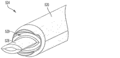
内側シャフト520の遠位先端部524が、図9Dでより詳細に示されており、図示のように、遠位先端部524は、過去の実施例について以前にも触れた突起部128と類似の突起部528を含む。図示の突起部528は、側壁602、604が結合して、シース600が閉じた構成にある場合、この突起部がシース600の内側ルーメンの形状と一致するよう、略楕円形の断面を有する。
The
図9Dで更に見られるように、内側シャフト520は、その遠位端で形成され、且つ、遠位先端部528の周囲で周方向に延出する溝529も、含められる。シース600の各側壁602、604の近位端に配置するよう、溝529を構成するために、溝529は、シース600の各側壁602、604の近位端の形状とサイズと一致する形状とサイズを有することができる。溝529によって、内側シャフト520の外側壁が、シース600の側壁602、604の近位端の周囲で延出することで、内側シャフト520がシース600に結合する際、シース600の移動(例えば、開放)が抑止される。従って、内側シャフト520は、シース600を閉じた位置に保つことになる。
As further seen in FIG. 9D, the
図10は、シース600とシース挿入器具500を完全に組み立てた構体を示しており、内側シャフト520の遠位先端部(図示せず)が、シース600内へと完全に挿入されている。図示のように、シース600のクロスバー610a、610bが、プロング502、504の遠位端のノッチ502n、504n内で配置され、更に、シース600がプロング502、504に対して遠位方向に移動することが防止されるよう、プロング502、504上のボス(2つのみのボス506a、506が図示されている)は、シース600上の歯の間を延出する(右側の歯608L間で延出するボス506a、506bが、示されている)。シース600の近位端は、外側シャフト510上のショルダー512と共に整列し、各側壁602、604の近位端は、内側シャフト520の溝529へと延出する。それ故、内側シャフト520は、骨孔内への挿入中、側壁602、604を閉じた位置で維持する。また、各側壁602、604の近位端を配置する溝529は、クロスバー610a、610bに加えられた力の一部を軽減するために、骨孔内への挿入中、遠位方向の力をシース600に加えるよう、機能する。シース600が完全に骨孔内へ挿入されたら、内側シャフト520を外側シャフト510から除去し、更に、シース600に向かってエキスパンダー400を送り、これによって、シース600を拡張、固定して、腱を骨孔内周囲で配置するために、外側シャフト510を通して、エキスパンダー挿入器具300を前進可能である。シース600が拡張する際、ボスがシース側壁602、604上の歯から外れるので、外側シャフト510も、続いて外すことができる。
FIG. 10 shows a fully assembled assembly of the
本明細書に記載した機構を使用して、シース、又は、固定具を種々の方法で骨内に移植できる。例えば、上腕二頭筋腱固定手術を実施するために、固定具を骨に移植する例示的方法の1つは、2015年1月30日付けで出願され、「Biceps Tenodesis Implants and Delivery Tools(上腕二頭筋腱固定インプラントと送達器具)」と題される米国特許出願第14/610,602号で述べられており、その内容全体を、参照により本明細書で援用する。 Using the mechanisms described herein, a sheath or fixture can be implanted into bone in a variety of ways. For example, one exemplary method of implanting a fastener into a bone to perform a biceps tendon fixation procedure was filed on Jan. 30, 2015, and is entitled “Biceps Tenodes Implants and Delivery Tools”. US patent application Ser. No. 14 / 610,602, entitled “Biceps tendon fixation implant and delivery device”, the entire contents of which are hereby incorporated by reference.
二頭筋腱固定手術では、外科医が相応しい大きさのインプラントや器具を選べるよう、二頭筋腱を好適な方法で取り出し、腱の大きさを決定する。更に、いくつかの実施例では、シース挿入器具100、又は、500を使用して、プロング108a、108b、又は、502、504により、腱の大きさを決定することができる。サイズが異なる器具は、種々のサイズのプロングやフォークを含められる。腱の大きさを正しく決定した後、適切なサイズのリーマを使用して、例えば、上腕骨などの骨内に孔を広げることができる。しかしながら、当業者であれば、任意の好適な骨孔調製技術や装置を使用して、骨孔を形成できることは、理解しているであろう。
In biceps tendon fixation surgery, the biceps tendon is removed in a suitable manner and the tendon size is determined so that the surgeon can select an appropriately sized implant or instrument. Further, in some embodiments,
プロングと周囲のシースとの間に位置する腱を容易に挿入できるよう、骨孔の直径を寸法決定できる。シース200’を使用する場合、このシース200’上の深さ停止タブ221a’、221b’によって、シースが骨孔内に入り過ぎるのを防止可能である。他の実施例において、外側シャフト、例えば、シース挿入器具100の外側シャフト102は、その中で形成され、挿入を示すレーザーマーキングを含められる。更に別の実施例では、外側シャフト、例えば、シース挿入器具500の外側シャフト510は、その内部に形成され、直径が骨孔と比較して長いショルダー512を含められ、これにより、外側シャフト510は、骨孔内に侵入することが防止される。
The diameter of the bone hole can be sized so that a tendon located between the prong and the surrounding sheath can be easily inserted. When using the sheath 200 ', the
骨内に骨孔を調製した後、挿入器ツールの遠位端に結合するシースを、骨孔内へ前進させるべき腱と隣接して配置できる。シースが結合する挿入器具を骨孔内で前進させて、シースを骨孔内の定位置に保持し、外側シャフト、例えば、外側シャフト102、あるいは、シャフト510を残しつつ、内側シャフト、例えば、内側シャフト104、あるいは、520を除去できる。エキスパンダー挿入器具、例えば、器具300は、外側シャフトを通じて結合するエキスパンダー400と共に前進可能であり、更に、シース内に送ることができる。エキスパンダー挿入器具が回転する間、柄が固定されたままとなるよう、執刀医は、シース挿入器具の外側シャフトに結合する柄を掴むことができる。かくして、シース挿入器具の外側シャフトは、シース内へのエキスパンダーの回転中、シースの回転を抑止する。エキスパンダーは、シースに対して、遠位端よりも長い距離まで、エキスパンダーを、近位端と共に径方向外側へと拡張させる。シースは、骨孔をこれらの間の腱と係合することで、腱を骨孔内で固定する。幾つかの実施例では、追加で誘導線、及び/又は、縫合糸を使用できることが理解されるであろう。
After preparing the bone hole in the bone, a sheath coupled to the distal end of the inserter tool can be placed adjacent to the tendon to be advanced into the bone hole. The insertion instrument to which the sheath is coupled is advanced within the bone hole to hold the sheath in place within the bone hole and leave the outer shaft, eg, the
当業者であれば、本明細書で開示した上腕二頭筋腱固定方法と装置が、骨孔を介して骨に取り付けられた腱への外傷や損傷を防止するための様々な外科手術で使用可能であることは、理解しているであろう。また、本発明は、従来の関節修復手術にも適用される。 One skilled in the art would use the biceps tendon fixation method and apparatus disclosed herein in various surgical procedures to prevent trauma and damage to tendons attached to the bone through the bone hole. You understand that it is possible. The present invention is also applied to conventional joint repair surgery.
本明細書で開示される装置は、1度使用したら廃棄されるように設計されるか、又は、複数回使用されるよう設計可能である。だが、いずれの場合も、本装置は、少なくとも1回使用してから再度使用するために再調整することができる。再調整には、装置の分解工程、それに続く特定部品の洗浄や交換工程、及び、その後の再組み立て工程の任意の組み合わせを含むことができる。特に、装置は分解可能であり、装置の任意の数の特定部品、又は、部分を、任意の組み合わせで選択的に交換、あるいは、取り除くことができる。特定の部分を洗浄、及び/又は、交換したら、装置は、後で使用するために、再調整施設において、又は、外科手術の直前に外科チームによるいずれかによって再組み立てすることができる。当業者であれば、装置の再調整が、分解、洗浄/交換、及び再組立のための様々な技術を利用できることは、理解しているであろう。このような技術の使用、及び、その結果もたらされる再調整後の装置は、全て本発明の範囲内にある。 The devices disclosed herein can be designed to be discarded after a single use, or can be designed to be used multiple times. In either case, however, the device can be readjusted to be used at least once and then used again. Reconditioning can include any combination of device disassembly steps followed by cleaning or replacement of specific parts and subsequent reassembly steps. In particular, the device can be disassembled and any number of specific parts or parts of the device can be selectively replaced or removed in any combination. Once a particular part has been cleaned and / or replaced, the device can be reassembled for later use either at a reconditioning facility or by a surgical team immediately prior to a surgical procedure. One skilled in the art will appreciate that reconditioning of the device can utilize a variety of techniques for disassembly, cleaning / replacement, and reassembly. The use of such techniques and the resulting reconditioned device are all within the scope of the present invention.
好ましくは、本明細書に記載する発明は、手術前に処理されるであろう。最初に、新規又は使用済みの器具を入手し、必要であれば洗浄する。次いで器具を滅菌することができる。ある滅菌技術では、器具は、プラスチックバッグ又はTYVEKバッグなど、閉じられて封止された容器に入れられる。次に、容器及び器具は、γ線、X線、及び高エネルギー電子など、容器を透過できる放射線照射野に入れられる。放射線は、器具上又は容器内の細菌を死滅させる。次に、滅菌された器具を滅菌容器に格納することができる。封止された容器は、医療設備において開封されるまで器具を滅菌状態に保つ。 Preferably, the invention described herein will be processed before surgery. First, obtain a new or used instrument and clean it if necessary. The instrument can then be sterilized. In one sterilization technique, the instrument is placed in a closed and sealed container, such as a plastic bag or a TYVEK bag. The container and instrument are then placed in a radiation field that can penetrate the container, such as gamma rays, x-rays, and high energy electrons. Radiation kills bacteria on the instrument or in the container. The sterilized instrument can then be stored in a sterile container. The sealed container keeps the instrument sterile until it is opened in the medical facility.
装置は滅菌されることが好ましい。これは、β線又はγ線、酸化エチレン、蒸気を含む、当業者に既知の任意の数の方法によって行うことができる。 The device is preferably sterilized. This can be done by any number of methods known to those skilled in the art including beta or gamma radiation, ethylene oxide, steam.
当業者であれば、上述の実施例に基づいた本発明の更なる特徴や利点が理解されよう。従って、本発明は、添付の特許請求の範囲によって示される場合を除き、具体的に示され、説明された内容により限定されるものではない。本明細書で引用される全ての公開物や参考文献は、その全容を参照により本明細書で明示的に援用される。 One skilled in the art will appreciate further features and advantages of the invention based on the above-described embodiments. Accordingly, the invention is not to be limited by what has been particularly shown and described, except as indicated by the appended claims. All publications and references cited herein are expressly incorporated herein by reference in their entirety.
〔実施の態様〕
(1) 固定具構体であって、
近位端と遠位端とを備える第1側壁、及び、近位端と遠位端とを備える第2側壁を有するシースであって、前記第1及び第2側壁の前記遠位端は、前記第1及び第2側壁がヒンジピンの周囲で互いに対して枢動できるよう、前記ヒンジピンによって互いに結合する、シースと、
略細長い円筒構成を有し、且つ、前記第1及び第2側壁を前記ヒンジピンの周囲で枢動させ、互いから離れるように横方向に移動させるために、前記シースの前記第1側壁と第2側壁との間で受容されるよう構成されているエキスパンダーとを含む、固定具構体。
(2) 前記第1及び第2側壁上の第1及び第2タブを更に含み、前記第1及び第2タブは、前記近位端と遠位端との間で前記第1及び第2側壁の略中間部に配置され、前記第1及び第2タブは、前記第1及び第2側壁の前記近位端が互いに隣接して配置される際、器具の一部を前記タブ間で受容するよう構成されている、実施態様1に記載の固定具構体。
(3) 前記第1及び第2側壁それぞれの前記近位端は、その上に形成され、且つ、前記シースと前記エキスパンダーとの間の整列を保つよう、前記エキスパンダー上のねじ山と係合するように構成されているボスを含む、実施態様1に記載の固定具構体。
(4) 各側壁上の前記ボスは、前記第1及び第2側壁の前記近位端が、前記エキスパンダーを略周方向に囲むよう、前記第1及び第2側壁のうちの他方の側壁に向かって延出する、実施態様3に記載の固定具構体。
(5) 前記第1及び第2側壁はそれぞれ、互いに面する内面、及び、反対側の外面を備え、前記第1及び第2側壁それぞれの前記外面は、その上に形成されたリブを含む、実施態様1に記載の固定具構体。
Embodiment
(1) A fixture structure,
A sheath having a first sidewall comprising a proximal end and a distal end, and a second sidewall comprising a proximal end and a distal end, wherein the distal ends of the first and second sidewalls are A sheath coupled to each other by the hinge pin so that the first and second sidewalls can pivot relative to each other about the hinge pin;
The first and second sidewalls of the sheath have a generally elongate cylindrical configuration and are configured to pivot the first and second sidewalls about the hinge pin and move laterally away from each other. An expander assembly including an expander configured to be received between the sidewalls.
(2) further comprising first and second tabs on the first and second sidewalls, the first and second tabs being between the proximal end and the distal end; The first and second tabs receive a portion of the instrument between the tabs when the proximal ends of the first and second sidewalls are positioned adjacent to each other. The fixture assembly according to embodiment 1, which is configured as described above.
(3) The proximal ends of each of the first and second sidewalls are formed thereon and engage threads on the expander to maintain alignment between the sheath and the expander. The fixture assembly of claim 1, including a boss configured as described above.
(4) The boss on each side wall faces the other side of the first and second side walls so that the proximal ends of the first and second side walls surround the expander in a substantially circumferential direction. The fixture assembly according to embodiment 3, wherein the fixture assembly extends.
(5) Each of the first and second side walls includes an inner surface facing each other and an outer surface on the opposite side, and each outer surface of the first and second side walls includes a rib formed thereon. The fixture assembly according to embodiment 1.
(6) 前記リブは、近位−遠位方向に延出して広がる縦軸と略垂直に延出している、実施態様5に記載の固定具構体。
(7) 前記第1及び第2側壁それぞれの外面は、少なくとも1列として構成されたリブの複数の行を備え、各リブは、近位−遠位方向に延出する縦軸と略垂直に延びている、実施態様1に記載の固定具構体。
(8) リブの最近位の行における少なくとも1つの前記リブは、高さが前記最近位の行から遠位にある前記行の前記リブの高さよりも高い、実施態様7に記載の固定具構体。
(9) 前記第1及び第2側壁はそれぞれ、孔が内部に形成され、且つ、前記ヒンジピンがそこを貫通する少なくとも1つの突起部を有する、実施態様1に記載の固定具構体。
(10) 前記第1側壁の前記遠位端は、内部に孔が形成されて、そこを前記ヒンジピンが貫通する第1突起部、及び、内部に孔が形成されて、そこを前記ヒンジピンが貫通する第2突起部を含み、前記第2側壁は、内部に孔が形成されて、そこを前記ヒンジピンが貫通する第3突起部、及び、内部に孔が形成されて、そこを前記ヒンジピンが貫通する第4突起部を含む、実施態様1に記載の固定具構体。
(6) The fixture assembly according to embodiment 5, wherein the rib extends substantially perpendicular to a longitudinal axis extending in the proximal-distal direction.
(7) The outer surface of each of the first and second sidewalls includes a plurality of rows of ribs configured in at least one column, each rib being substantially perpendicular to a longitudinal axis extending in a proximal-distal direction.
8. The fixture assembly of embodiment 7, wherein at least one of the ribs in the nearest row of ribs has a height that is higher than the height of the rib in the row distal to the nearest row. .
(9) The fixture assembly according to embodiment 1, wherein each of the first and second side walls has a hole formed therein, and the hinge pin has at least one protrusion passing therethrough.
(10) The distal end of the first side wall has a hole formed therein, a first protrusion through which the hinge pin passes, and a hole formed therein, through which the hinge pin passes. The second sidewall has a hole formed therein, a third protrusion through which the hinge pin passes, and a hole formed therein, through which the hinge pin passes. The fixing tool assembly according to Embodiment 1, including a fourth projecting portion.
(11) 前記第3突起部は、前記第1突起部と第2突起部との間に配置され、前記第2突起部は、前記第3突起部と第4突起部との間に配置されている、実施態様10に記載の固定具構体。
(12) 前記第1及び第2側壁の少なくとも1つに近位タブを更に含み、前記近位タブは、前記タブが骨孔への前記シースの挿入深さを制限するのに有効となるよう、前記側壁から径方向外側に延出している、実施態様1に記載の固定具構体。
(13) 前記第1及び第2側壁はそれぞれ、略長方形の形状を有し、その1面には、前記エキスパンダーを配置するための半円柱状の空洞が形成されている、実施態様1に記載の固定具構体。
(14) 前記第1及び第2側壁の少なくとも1つは、その上に形成され、且つ、内部を貫通する縫合糸受容開口部を画定する縫合糸受容タブを含む、実施態様1に記載の固定具構体。
(15) 前記縫合糸受容タブは、前記縫合糸受容開口部が前記シースの縦軸と略平行に延出する中心軸を有するように、前記シースの前記縦軸と略垂直に延出している、実施態様14に記載の固定具構体。
(11) The third protrusion is disposed between the first protrusion and the second protrusion, and the second protrusion is disposed between the third protrusion and the fourth protrusion. The fixture assembly according to
(12) Further comprising a proximal tab on at least one of the first and second sidewalls, the proximal tab being effective to limit the insertion depth of the sheath into the bone hole. The fixture assembly according to embodiment 1, which extends radially outward from the side wall.
(13) Embodiment 1 in which each of the first and second side walls has a substantially rectangular shape, and a semi-cylindrical cavity for arranging the expander is formed on one surface thereof. Fixture structure.
14. The fixation of embodiment 1, wherein at least one of the first and second sidewalls includes a suture receiving tab formed thereon and defining a suture receiving opening therethrough. The structure.
(15) The suture receiving tab extends substantially perpendicular to the longitudinal axis of the sheath such that the suture receiving opening has a central axis extending substantially parallel to the longitudinal axis of the sheath. The fixture assembly according to embodiment 14.
(16) 骨固定具挿入器具であって、
近位端と遠位端と、内部を貫通する内側ルーメンと、を備える細長いシャフトを含み、前記遠位端は、そこから遠位方向に延び、且つ、前記シャフトの両側に配置された第1及び第2プロングを含み、各プロングは、各プロングの近位端と隣接して配置された第1対のボス、並びに、各プロングの中間部と隣接して配置された第2対のボスを有する、骨固定具挿入器具。
(17) 前記第1対のボスは、各プロングから第1距離まで径方向外側に延出し、前記第2対のボスは、各プロングから、前記第1距離よりも短い第2距離まで径方向外側に延出している、実施態様16に記載の骨固定具挿入器具。
(18) 前記細長いシャフトは、前記細長いシャフトの前記内側ルーメンを見られるよう、前記第1及び第2プロングに近位の位置で前記細長いシャフトの側壁内に形成された少なくとも1つの観察窓を含む、実施態様16に記載の骨固定具挿入器具。
(19) 腱固定機構であって、
第1及び第2側壁がヒンジピンの周囲で互いに対して枢動するように構成されるよう、前記ヒンジピンによって遠位端で結合する前記第1及び第2側壁を備えるシースを有する固定具構体であって、各側壁は、その上に形成された回転防止ボスを備える、固定具構体と、
近位端と遠位端との間で内部を貫通する内側ルーメンを有する細長いシャフトを備える挿入器具であって、前記遠位端は、その両側から遠位方向に延出し、且つ、第1及び第2プロングを各側壁上の前記回転防止ボス間で係合して、前記第1及び第2プロングに対する前記シースの回転を防止するために、前記シースの前記第1及び第2側壁の両側に沿って延出するように構成されている前記第1及び第2プロングを有する、挿入器具とを含む、腱固定機構。
(20) 各側壁は、前記回転防止ボスの近位に配置され、且つ、前記固定具構体の前記第1側壁と第2側壁との間に配置されたエキスパンダーと係合するように構成された保持ボスを更に含む、実施態様19に記載の機構。
(16) A bone anchor insertion device,
A elongated shaft comprising a proximal end and a distal end and an inner lumen extending therethrough, wherein the distal end extends distally therefrom and is disposed on opposite sides of the shaft. Each prong includes a first pair of bosses disposed adjacent to the proximal end of each prong, and a second pair of bosses disposed adjacent to the middle portion of each prong. A bone anchor insertion device.
(17) The first pair of bosses extend radially outward from each prong to a first distance, and the second pair of bosses radially from each prong to a second distance shorter than the first distance. Embodiment 17. The bone anchor insertion device of embodiment 16 extending outward.
(18) The elongate shaft includes at least one viewing window formed in a side wall of the elongate shaft at a location proximal to the first and second prongs so that the inner lumen of the elongate shaft can be seen. The bone anchor insertion device according to embodiment 16, wherein:
(19) A tendon fixation mechanism,
A fixture assembly having a sheath with the first and second side walls coupled at a distal end by the hinge pin such that the first and second side walls are configured to pivot relative to each other about the hinge pin. Each side wall includes a fixture assembly comprising an anti-rotation boss formed thereon;
An insertion instrument comprising an elongate shaft having an inner lumen extending therethrough between a proximal end and a distal end, said distal end extending distally from both sides thereof, and first and A second prong is engaged between the anti-rotation bosses on each side wall to prevent rotation of the sheath relative to the first and second prongs on both sides of the first and second side walls of the sheath. A tendon fixation mechanism comprising an insertion instrument having said first and second prongs configured to extend along.
(20) Each side wall is disposed in proximity to the anti-rotation boss and is configured to engage with an expander disposed between the first side wall and the second side wall of the fixture assembly. The mechanism of embodiment 19, further comprising a retention boss.
(21) 前記第1及び第2プロングはそれぞれ、前記第1及び第2側壁上の前記保持ボスの近位に配置された近位ボス、並びに、前記第1及び第2側壁上の前記回転防止ボスの近位、且つ、前記第1及び第2側壁上の前記保持ボスの遠位に配置された遠位ボスを含む、実施態様20に記載の機構。
(22) 略細長い円筒構成を有し、且つ、前記第1及び第2側壁を前記ヒンジピンの周囲で枢動させ、互いから離れるよう横方向に移動させるために、前記シースの前記第1側壁と第2側壁との間で受容されるように構成されているエキスパンダーを更に含む、実施態様19に記載の機構。
(23) 前記第1及び第2側壁の少なくとも1つの近位端は、そこから径方向外側に延出するタブを備え、前記タブは、前記シースと前記挿入器具との間の係合が容易となるよう、前記挿入器具の前記細長いシャフトにおける前記遠位端のスロット内で受容される、実施態様19に記載の機構。
(21) The first and second prongs are respectively a proximal boss disposed proximal to the holding boss on the first and second side walls, and the anti-rotation on the first and second side walls. 21. The mechanism of embodiment 20, comprising a distal boss disposed proximal to the boss and distal to the retaining boss on the first and second sidewalls.
(22) having a generally elongate cylindrical configuration and for pivoting the first and second side walls about the hinge pin and moving them laterally away from each other; 20. The mechanism of embodiment 19, further comprising an expander configured to be received between the second sidewall.
(23) At least one proximal end of the first and second sidewalls includes a tab extending radially outward therefrom, the tab being easy to engage between the sheath and the insertion instrument 20. The mechanism of embodiment 19, wherein the mechanism is received in a slot at the distal end of the elongate shaft of the insertion instrument.
Claims (23)
近位端と遠位端とを備える第1側壁、及び、近位端と遠位端とを備える第2側壁を有するシースであって、前記第1及び第2側壁の前記遠位端は、前記第1及び第2側壁がヒンジピンの周囲で互いに対して枢動できるよう、前記ヒンジピンによって互いに結合する、シースと、
略細長い円筒構成を有し、且つ、前記第1及び第2側壁を前記ヒンジピンの周囲で枢動させ、互いから離れるように横方向に移動させるために、前記シースの前記第1側壁と第2側壁との間で受容されるよう構成されているエキスパンダーとを含む、固定具構体。 A fixture structure,
A sheath having a first sidewall comprising a proximal end and a distal end, and a second sidewall comprising a proximal end and a distal end, wherein the distal ends of the first and second sidewalls are A sheath coupled to each other by the hinge pin so that the first and second sidewalls can pivot relative to each other about the hinge pin;
The first and second sidewalls of the sheath have a generally elongate cylindrical configuration and are configured to pivot the first and second sidewalls about the hinge pin and move laterally away from each other. An expander assembly including an expander configured to be received between the sidewalls.
近位端と遠位端と、内部を貫通する内側ルーメンと、を備える細長いシャフトを含み、前記遠位端は、そこから遠位方向に延び、且つ、前記シャフトの両側に配置された第1及び第2プロングを含み、各プロングは、各プロングの近位端と隣接して配置された第1対のボス、並びに、各プロングの中間部と隣接して配置された第2対のボスを有する、骨固定具挿入器具。 A bone anchor insertion device,
A elongated shaft comprising a proximal end and a distal end and an inner lumen extending therethrough, wherein the distal end extends distally therefrom and is disposed on opposite sides of the shaft. Each prong includes a first pair of bosses disposed adjacent to the proximal end of each prong, and a second pair of bosses disposed adjacent to the middle portion of each prong. A bone anchor insertion device.
第1及び第2側壁がヒンジピンの周囲で互いに対して枢動するように構成されるよう、前記ヒンジピンによって遠位端で結合する前記第1及び第2側壁を備えるシースを有する固定具構体であって、各側壁は、その上に形成された回転防止ボスを備える、固定具構体と、
近位端と遠位端との間で内部を貫通する内側ルーメンを有する細長いシャフトを備える挿入器具であって、前記遠位端は、その両側から遠位方向に延出し、且つ、第1及び第2プロングを各側壁上の前記回転防止ボス間で係合して、前記第1及び第2プロングに対する前記シースの回転を防止するために、前記シースの前記第1及び第2側壁の両側に沿って延出するように構成されている前記第1及び第2プロングを有する、挿入器具とを含む、腱固定機構。 Tendon fixation mechanism,
A fixture assembly having a sheath with the first and second side walls coupled at a distal end by the hinge pin such that the first and second side walls are configured to pivot relative to each other about the hinge pin. Each side wall includes a fixture assembly comprising an anti-rotation boss formed thereon;
An insertion instrument comprising an elongate shaft having an inner lumen extending therethrough between a proximal end and a distal end, said distal end extending distally from both sides thereof, and first and A second prong is engaged between the anti-rotation bosses on each side wall to prevent rotation of the sheath relative to the first and second prongs on both sides of the first and second side walls of the sheath. A tendon fixation mechanism comprising an insertion instrument having said first and second prongs configured to extend along.
Priority Applications (1)
| Application Number | Priority Date | Filing Date | Title |
|---|---|---|---|
| JP2022072228A JP2022090128A (en) | 2016-04-08 | 2022-04-26 | Tenodesis implants and tools |
Applications Claiming Priority (2)
| Application Number | Priority Date | Filing Date | Title |
|---|---|---|---|
| US15/093,938 | 2016-04-08 | ||
| US15/093,938 US10231823B2 (en) | 2016-04-08 | 2016-04-08 | Tenodesis implants and tools |
Related Child Applications (1)
| Application Number | Title | Priority Date | Filing Date |
|---|---|---|---|
| JP2022072228A Division JP2022090128A (en) | 2016-04-08 | 2022-04-26 | Tenodesis implants and tools |
Publications (2)
| Publication Number | Publication Date |
|---|---|
| JP2017192718A true JP2017192718A (en) | 2017-10-26 |
| JP7224751B2 JP7224751B2 (en) | 2023-02-20 |
Family
ID=58544783
Family Applications (2)
| Application Number | Title | Priority Date | Filing Date |
|---|---|---|---|
| JP2017076546A Active JP7224751B2 (en) | 2016-04-08 | 2017-04-07 | Tendon fixation implants and instruments |
| JP2022072228A Pending JP2022090128A (en) | 2016-04-08 | 2022-04-26 | Tenodesis implants and tools |
Family Applications After (1)
| Application Number | Title | Priority Date | Filing Date |
|---|---|---|---|
| JP2022072228A Pending JP2022090128A (en) | 2016-04-08 | 2022-04-26 | Tenodesis implants and tools |
Country Status (6)
| Country | Link |
|---|---|
| US (3) | US10231823B2 (en) |
| EP (2) | EP3459497B1 (en) |
| JP (2) | JP7224751B2 (en) |
| CN (3) | CN114451943B (en) |
| AU (1) | AU2017201948B2 (en) |
| BR (1) | BR102017007161B1 (en) |
Cited By (1)
| Publication number | Priority date | Publication date | Assignee | Title |
|---|---|---|---|---|
| KR20230006679A (en) * | 2021-07-01 | 2023-01-11 | 주식회사 제일메디칼코퍼레이션 | Leg screw for bone fixation having functions of length control and protrusion prevention |
Families Citing this family (18)
| Publication number | Priority date | Publication date | Assignee | Title |
|---|---|---|---|---|
| US10729419B2 (en) | 2014-10-23 | 2020-08-04 | Medos International Sarl | Biceps tenodesis implants and delivery tools |
| US10751161B2 (en) | 2014-10-23 | 2020-08-25 | Medos International Sárl | Biceps tenodesis anchor implants |
| US10856966B2 (en) | 2014-10-23 | 2020-12-08 | Medos International Sarl | Biceps tenodesis implants and delivery tools |
| US10076374B2 (en) | 2014-10-23 | 2018-09-18 | Medos International Sárl | Biceps tenodesis delivery tools |
| US10034742B2 (en) | 2014-10-23 | 2018-07-31 | Medos International Sarl | Biceps tenodesis implants and delivery tools |
| US10675142B2 (en) * | 2015-04-16 | 2020-06-09 | Mv N8Tive, Llc | Fixation device and tissue fixation method for ACL reconstruction |
| US9693856B2 (en) | 2015-04-22 | 2017-07-04 | DePuy Synthes Products, LLC | Biceps repair device |
| US10231824B2 (en) | 2016-04-08 | 2019-03-19 | Medos International Sárl | Tenodesis anchoring systems and tools |
| US10231823B2 (en) | 2016-04-08 | 2019-03-19 | Medos International Sarl | Tenodesis implants and tools |
| US10709435B2 (en) | 2016-04-20 | 2020-07-14 | Medos International Sarl | Meniscal repair devices, systems, and methods |
| US10743981B2 (en) * | 2017-02-16 | 2020-08-18 | L. Pearce McCarty, III | Tendon anchoring |
| CN108784764B (en) * | 2018-04-10 | 2024-06-28 | 上海市第六人民医院 | Powered Compression Suture Anchor |
| KR102176328B1 (en) * | 2018-12-27 | 2020-11-09 | 고려대학교 산학협력단 | Perforator integral suture anchor device |
| US20210137513A1 (en) * | 2019-11-11 | 2021-05-13 | Smith & Nephew, Inc. | Healicoil knotless outer driver retention feature |
| CN112089486B (en) * | 2020-09-01 | 2021-06-15 | 吉林大学 | Pedicle screw tail tooth breaker structure capable of reducing injury |
| CN113974730B (en) * | 2021-12-30 | 2022-04-22 | 杭州锐健马斯汀医疗器材有限公司 | Fixing system |
| DE102023117078A1 (en) * | 2022-07-01 | 2024-01-04 | Inovedis Gmbh | SINEFIX instruments |
| CN116269567B (en) * | 2023-05-23 | 2023-09-12 | 杭州翡宠生物科学有限公司 | suture tensioning device |
Citations (5)
| Publication number | Priority date | Publication date | Assignee | Title |
|---|---|---|---|---|
| US20090306671A1 (en) * | 2008-06-06 | 2009-12-10 | Providence Medical Technology, Inc. | Facet joint implants and delivery tools |
| JP2012532684A (en) * | 2009-07-09 | 2012-12-20 | スミス アンド ネフュー インコーポレーテッド | Tissue graft anchor assembly and instrument for use therewith |
| JP2013208484A (en) * | 2006-09-29 | 2013-10-10 | Depuy Mitek Llc | Femoral fixation |
| WO2014150053A1 (en) * | 2013-03-15 | 2014-09-25 | Kfx Medical Corporation | System and method for securing tissue to bone |
| US20150190130A1 (en) * | 2014-01-06 | 2015-07-09 | Groh Enterprises | Device and method for anchoring soft tissue to bone |
Family Cites Families (376)
| Publication number | Priority date | Publication date | Assignee | Title |
|---|---|---|---|---|
| US651949A (en) | 1899-10-05 | 1900-06-19 | Theron R Lillie | Screw holder and driver. |
| US775427A (en) | 1904-05-02 | 1904-11-22 | Charles Lusted Sr | Screw holder and driver. |
| US1426320A (en) | 1921-11-28 | 1922-08-15 | Peter M Savage | Holder for screws, nails, and the like |
| US1925385A (en) | 1932-11-08 | 1933-09-05 | Homer C Humes | Screw driver with screw holders |
| US2243717A (en) | 1938-09-20 | 1941-05-27 | Moreira Franciseo Elias Godoy | Surgical device |
| US2288584A (en) | 1940-05-23 | 1942-06-30 | Harry Herschel Leiter | Surgeon's screw driver, screw holder, and stabilizer |
| US2381050A (en) | 1943-12-04 | 1945-08-07 | Mervyn G Hardinge | Fracture reducing device |
| US2484655A (en) | 1947-07-14 | 1949-10-11 | Clifford B Shreve | Screw holder for screw drivers |
| US3073189A (en) | 1960-09-30 | 1963-01-15 | Stalker Drill Works Ltd | Drills |
| US3103926A (en) | 1961-01-13 | 1963-09-17 | Orthopaedic Specialties Corp | Surgical bone pin |
| US3089359A (en) | 1961-05-08 | 1963-05-14 | Nat Twist Drill & Tool Company | Drill construction |
| US3130763A (en) | 1962-09-13 | 1964-04-28 | Schlosser Bernard | Drills for cutting wooden plugs with cross grain |
| US3298410A (en) | 1964-01-31 | 1967-01-17 | Morifuji Haguruma Seisakusho C | Screw holder structure for use with screw drivers |
| JPS6021537Y2 (en) | 1979-06-12 | 1985-06-27 | 日産自動車株式会社 | Connector |
| GB2084468B (en) | 1980-09-25 | 1984-06-06 | South African Inventions | Surgical implant |
| US4641640A (en) | 1982-01-18 | 1987-02-10 | Calvin Griggs | Compression screw assembly |
| US4512344A (en) | 1982-05-12 | 1985-04-23 | Barber Forest C | Arthroscopic surgery dissecting apparatus |
| DE3309860A1 (en) | 1983-02-08 | 1984-08-09 | Fa. Gottlieb Gühring, 7470 Albstadt | DRILLING TOOL |
| US4503737A (en) | 1983-04-11 | 1985-03-12 | Digiovanni Donald | Threaded fastener removing tool |
| US4687392A (en) | 1984-04-17 | 1987-08-18 | Bidwell Robert E | Torque limiting fastener |
| US4592346A (en) | 1985-04-08 | 1986-06-03 | Jurgutis John A | Orthopedic staple |
| US4711232A (en) | 1985-07-12 | 1987-12-08 | Artur Fischer | Bone fastener and method of installing same |
| US4640271A (en) | 1985-11-07 | 1987-02-03 | Zimmer, Inc. | Bone screw |
| US4924865A (en) | 1986-05-20 | 1990-05-15 | Concept, Inc. | Repair tack for bodily tissue |
| US4919130A (en) | 1986-11-07 | 1990-04-24 | Nestle S.A. | Tool for inserting compressible intraocular lenses into the eye and method |
| US4901717A (en) | 1987-01-05 | 1990-02-20 | Moore Robert R | Tendon leader |
| US4773417A (en) | 1987-01-05 | 1988-09-27 | Moore Robert R | Method for using a tendon stripper and leader set |
| US4858810A (en) | 1987-04-30 | 1989-08-22 | Heart Technology, Inc. | Quick acting pin vise for use with angiographic guidewires |
| DE3818652A1 (en) | 1988-06-01 | 1989-12-14 | Fischer Artur Werke Gmbh | SPREADING PLUG FROM PLASTIC |
| US4960420A (en) | 1988-08-23 | 1990-10-02 | Marlowe Goble E | Channel ligament clamp and system |
| US4871289A (en) | 1988-11-25 | 1989-10-03 | Olympic Manufacturing Group, Inc. | Expansion fastener |
| US4988351A (en) | 1989-01-06 | 1991-01-29 | Concept, Inc. | Washer for use with cancellous screw for attaching soft tissue to bone |
| US4950270A (en) | 1989-02-03 | 1990-08-21 | Boehringer Mannheim Corporation | Cannulated self-tapping bone screw |
| US5129906A (en) | 1989-09-08 | 1992-07-14 | Linvatec Corporation | Bioabsorbable tack for joining bodily tissue and in vivo method and apparatus for deploying same |
| GB8924806D0 (en) | 1989-11-03 | 1989-12-20 | Neoligaments Ltd | Prosthectic ligament system |
| US5029573A (en) | 1990-03-30 | 1991-07-09 | Chow James C | System for endoscopic surgery |
| US5236445A (en) | 1990-07-02 | 1993-08-17 | American Cyanamid Company | Expandable bone anchor and method of anchoring a suture to a bone |
| US5026376A (en) | 1990-07-13 | 1991-06-25 | Greenberg Alex M | Surgical drill guide and retractor |
| US5133720A (en) | 1990-07-13 | 1992-07-28 | Greenberg Alex M | Surgical drill guide and retractor |
| US5746743A (en) | 1990-07-13 | 1998-05-05 | Greenberg Surgical Technologies, Llc | Single-handed surgical drill depth guide with mandibular retractor |
| EP0547134B1 (en) | 1990-09-04 | 1997-10-15 | Hip Developments Pty. Ltd. | Surgical screw |
| US7074203B1 (en) | 1990-09-25 | 2006-07-11 | Depuy Mitek, Inc. | Bone anchor and deployment device therefor |
| US5180384A (en) | 1991-02-08 | 1993-01-19 | Mikhail Michael W E | Method for implanting a patellar prosthesis |
| DE4106823C1 (en) | 1991-03-04 | 1992-06-25 | Liebscher Kunststofftechnik, 8032 Graefelfing, De | |
| US5234435A (en) | 1991-03-08 | 1993-08-10 | Seagrave Jr Richard A | Surgical method and apparatus |
| US5480403A (en) | 1991-03-22 | 1996-01-02 | United States Surgical Corporation | Suture anchoring device and method |
| US5720753A (en) | 1991-03-22 | 1998-02-24 | United States Surgical Corporation | Orthopedic fastener |
| CA2063159C (en) | 1991-03-22 | 1999-06-15 | Thomas W. Sander | Orthopedic fastener |
| US5105690A (en) | 1991-03-29 | 1992-04-21 | Implant Innovations, Inc. | Manipulator-driver for holding and driving a screw-type article |
| US5203864A (en) | 1991-04-05 | 1993-04-20 | Phillips Edward H | Surgical fastener system |
| EP0520177B1 (en) | 1991-05-24 | 1995-12-13 | Synthes AG, Chur | Resorbable tendon and bone augmentation device |
| US5116337A (en) | 1991-06-27 | 1992-05-26 | Johnson Lanny L | Fixation screw and method for ligament reconstruction |
| FR2678823B1 (en) | 1991-07-11 | 1995-07-07 | Legrand Jean Jacques | DEVICE FOR REINFORCING A LIGAMENT DURING A LIGAMENT PLASTY. |
| US5282816A (en) | 1991-09-20 | 1994-02-01 | Milres Corporation | Apparatus for subligamentous endoscopic transverse carpal ligament release surgery |
| US5325883A (en) | 1991-11-04 | 1994-07-05 | Orr Terrence R | Device and method for carpal tunnel release |
| US5226890A (en) | 1991-11-13 | 1993-07-13 | United States Surgical Corporation | Tissue gripping device |
| US5273024A (en) | 1992-01-22 | 1993-12-28 | Linvatec Corporation | Method and apparatus for performing endoscopic surgery |
| US5320626A (en) | 1992-02-19 | 1994-06-14 | Arthrex Inc. | Endoscopic drill guide |
| US5211647A (en) | 1992-02-19 | 1993-05-18 | Arthrex Inc. | Interference screw and cannulated sheath for endosteal fixation of ligaments |
| US5425733A (en) | 1992-02-19 | 1995-06-20 | Arthrex, Inc. | Interference screw with rounded back end and cannulated sheath for endosteal fixation of ligaments |
| US5385541A (en) | 1992-04-24 | 1995-01-31 | Loma Linda University Medical Center | Cerebrospinal fluid shunt capable of minimal invasive revision |
| EP0637944B1 (en) | 1992-04-28 | 1998-03-25 | Donald R. Huene | Absorbable bone screw and tool for its insertion |
| US5242418A (en) | 1992-05-22 | 1993-09-07 | Weinstein James D | Protective means for a needle or similar cannula medical device |
| US5226714A (en) | 1992-05-26 | 1993-07-13 | Wright Jack V | Pivoting drawer slide system |
| US5250055A (en) | 1992-06-08 | 1993-10-05 | Orthopedic Systems Inc. | Method and apparatus for tying suture to bone |
| US5258012A (en) | 1992-06-30 | 1993-11-02 | Ethicon, Inc. | Surgical fasteners |
| FR2693899B1 (en) | 1992-07-24 | 1994-09-23 | Laboureau Jacques | Osteosynthesis plate clip. |
| US5445642A (en) | 1992-09-01 | 1995-08-29 | Depuy Inc. | Method for installing a femoral component |
| US5624446A (en) | 1992-09-11 | 1997-04-29 | University Of Washington | System for repair of capsulo-labral separations |
| US5266075A (en) | 1992-10-05 | 1993-11-30 | Roy Clark | Tendon threader for endosteal ligament mounting |
| US5314427A (en) | 1992-10-13 | 1994-05-24 | Marlowe Goble E | Channel ligament clamp |
| FR2700464B1 (en) | 1992-11-13 | 1995-04-14 | Maurice Bertholet | Connecting piece for bone elements. |
| US5352231A (en) | 1992-11-23 | 1994-10-04 | Danek Medical, Inc. | Nut starter wrench for orthopedic fixation system |
| US5380334A (en) | 1993-02-17 | 1995-01-10 | Smith & Nephew Dyonics, Inc. | Soft tissue anchors and systems for implantation |
| US5325868A (en) | 1993-05-04 | 1994-07-05 | Kimmelstiel Carey D | Self-gripping medical wire torquer |
| US5352229A (en) | 1993-05-12 | 1994-10-04 | Marlowe Goble E | Arbor press staple and washer and method for its use |
| US5718706A (en) | 1993-06-04 | 1998-02-17 | Hip Developments Pty. Ltd. | Surgical screw and washer |
| US5505735A (en) | 1993-06-10 | 1996-04-09 | Mitek Surgical Products, Inc. | Surgical anchor and method for using the same |
| US5632748A (en) | 1993-06-14 | 1997-05-27 | Linvatec Corporation | Endosteal anchoring device for urging a ligament against a bone surface |
| CA2131141A1 (en) | 1993-09-24 | 1995-03-25 | James A. Boucher | Ligament graft protection apparatus and method |
| US5454811A (en) | 1993-11-08 | 1995-10-03 | Smith & Nephew Dyonics, Inc. | Cam lock orthopedic fixation screw and method |
| US5425490A (en) | 1994-01-18 | 1995-06-20 | Goble; E. Marlowe | Instrument with dual holding feature |
| US5478329A (en) | 1994-05-06 | 1995-12-26 | Ternamian; Artin M. | Trocarless rotational entry cannula |
| US5607432A (en) | 1995-01-23 | 1997-03-04 | Linvatec Corporation | Threaded suture anchor retriever |
| US5601562A (en) | 1995-02-14 | 1997-02-11 | Arthrex, Inc. | Forked insertion tool and metnod of arthroscopic surgery using the same |
| SE509262C2 (en) | 1995-03-02 | 1998-12-21 | Sandvik Ab | Drill with cooling ducts and means for making them |
| US5897565A (en) | 1995-03-06 | 1999-04-27 | Vance Products Incorporated | Releasable, surgical clamp |
| AU5312496A (en) | 1995-03-16 | 1996-10-02 | Medtronic Ps Medical | Partially disposable surgical imaging assembly |
| DE69737756T2 (en) | 1995-03-27 | 2008-01-31 | Warsaw Orthopedic, Inc., Minneapolis | Spinal fusion implant |
| US5660186A (en) | 1995-06-07 | 1997-08-26 | Marshfield Clinic | Spiral biopsy stylet |
| AU129851S (en) | 1995-06-23 | 1997-05-07 | Roussel Uclaf | Manually operated implantation instrument for use with implant caskets |
| JPH11511357A (en) | 1995-08-25 | 1999-10-05 | グロッツ,アール・トーマス | Stabilizer for human joints |
| US5655330A (en) | 1995-10-25 | 1997-08-12 | Parsons, Iii; Henry S. | Slab pattern tool for termite treatment drilling |
| US5662657A (en) | 1996-01-17 | 1997-09-02 | Sunmed, Inc. | Intramedullary bone plug |
| US5899906A (en) | 1996-01-18 | 1999-05-04 | Synthes (U.S.A.) | Threaded washer |
| US5669925A (en) | 1996-02-06 | 1997-09-23 | Saunders; Michael R. | Soft tissue graft introducer |
| US5957953A (en) | 1996-02-16 | 1999-09-28 | Smith & Nephew, Inc. | Expandable suture anchor |
| EP1356790A3 (en) | 1996-02-16 | 2004-01-14 | Smith & Nephew, Inc. | Graft Anchor |
| CA2197614C (en) | 1996-02-20 | 2002-07-02 | Charles S. Taylor | Surgical instruments and procedures for stabilizing the beating heart during coronary artery bypass graft surgery |
| US5653763A (en) * | 1996-03-29 | 1997-08-05 | Fastenetix, L.L.C. | Intervertebral space shape conforming cage device |
| US5961538A (en) | 1996-04-10 | 1999-10-05 | Mitek Surgical Products, Inc. | Wedge shaped suture anchor and method of implantation |
| JP2007050269A (en) | 1996-05-09 | 2007-03-01 | Olympus Corp | Cavity retaining tool for bone surgery |
| FR2750595B1 (en) | 1996-07-02 | 1998-12-04 | Dev Sed Soc Et | MEDICAL SCREWS ESPECIALLY FOR SURGERY AND ANCILLARY OF POSITION |
| US6319270B1 (en) | 1996-08-05 | 2001-11-20 | Arthrex, Inc. | Headed bioabsorbable tissue anchor |
| US6984241B2 (en) | 1996-09-13 | 2006-01-10 | Tendon Technology, Ltd. | Apparatus and methods for tendon or ligament repair |
| US7611521B2 (en) | 1996-09-13 | 2009-11-03 | Tendon Technology, Ltd. | Apparatus and methods for tendon or ligament repair |
| US5948000A (en) | 1996-10-03 | 1999-09-07 | United States Surgical Corporation | System for suture anchor placement |
| US5948001A (en) | 1996-10-03 | 1999-09-07 | United States Surgical Corporation | System for suture anchor placement |
| US5899938A (en) | 1996-11-27 | 1999-05-04 | Joseph H. Sklar | Graft ligament anchor and method for attaching a graft ligament to a bone |
| US7083647B1 (en) | 1996-11-27 | 2006-08-01 | Sklar Joseph H | Fixation screw, graft ligament anchor assembly, and method for securing a graft ligament in a bone tunnel |
| US6554862B2 (en) | 1996-11-27 | 2003-04-29 | Ethicon, Inc. | Graft ligament anchor and method for attaching a graft ligament to a bone |
| US6533816B2 (en) | 1999-02-09 | 2003-03-18 | Joseph H. Sklar | Graft ligament anchor and method for attaching a graft ligament to a bone |
| US5702398A (en) | 1997-02-21 | 1997-12-30 | Tarabishy; Sam | Tension screw |
| US5904685A (en) | 1997-04-11 | 1999-05-18 | Stryker Corporation | Screw sheath |
| US6143016A (en) | 1997-04-21 | 2000-11-07 | Advanced Cardiovascular Systems, Inc. | Sheath and method of use for a stent delivery system |
| US6280472B1 (en) | 1997-07-23 | 2001-08-28 | Arthrotek, Inc. | Apparatus and method for tibial fixation of soft tissue |
| US6379386B1 (en) | 1997-09-09 | 2002-04-30 | Stryker Technologies Corporation | Anatomic glenoid shoulder prosthesis together with methods and tools for implanting same |
| WO1999015084A1 (en) | 1997-09-22 | 1999-04-01 | Schultz Leonard S | Surgical instruments for minimally invasive surgical procedures |
| AU739276B2 (en) | 1997-09-24 | 2001-10-11 | Ethicon Inc. | ACL fixation pin and method |
| US5906632A (en) | 1997-10-03 | 1999-05-25 | Innovasive Devices, Inc. | Intratunnel attachment device and system for a flexible load-bearing structure and method of use |
| US6027523A (en) | 1997-10-06 | 2000-02-22 | Arthrex, Inc. | Suture anchor with attached disk |
| US5895351A (en) | 1998-02-06 | 1999-04-20 | Arthrotek Inc. | Tissue distracting cannula |
| US6024758A (en) | 1998-02-23 | 2000-02-15 | Thal; Raymond | Two-part captured-loop knotless suture anchor assembly |
| US5993458A (en) | 1998-06-25 | 1999-11-30 | Ethicon, Inc. | Method of ultrasonically embedding bone anchors |
| US6221107B1 (en) | 1998-08-03 | 2001-04-24 | Mark E. Steiner | Ligament fixation device and method |
| US6251119B1 (en) | 1998-08-07 | 2001-06-26 | Embol-X, Inc. | Direct stick tear-away introducer and methods of use |
| US6355066B1 (en) | 1998-08-19 | 2002-03-12 | Andrew C. Kim | Anterior cruciate ligament reconstruction hamstring tendon fixation system |
| BR9805340B1 (en) | 1998-12-14 | 2009-01-13 | variable expansion insert for spinal stabilization. | |
| US6117139A (en) | 1998-12-25 | 2000-09-12 | Nagoya Screw Mfg., Co., Ltd. | Ligament graft-securing device |
| DE60037696T2 (en) | 1999-02-02 | 2009-01-08 | Arthrex Inc., Naples | Bioresorbable tissue stapling with oval shaped head |
| US6143017A (en) | 1999-03-17 | 2000-11-07 | Thal; Raymond | Free loop knotless suture anchor assembly |
| US6325805B1 (en) | 1999-04-23 | 2001-12-04 | Sdgi Holdings, Inc. | Shape memory alloy staple |
| US6464706B1 (en) | 1999-06-10 | 2002-10-15 | Thomas F. Winters | Tissue fixation device and method |
| US6123711A (en) | 1999-06-10 | 2000-09-26 | Winters; Thomas F. | Tissue fixation device and method |
| US6746450B1 (en) | 1999-07-07 | 2004-06-08 | Children's Hospital Medical Center | Spinal correction system |
| US6283948B1 (en) | 1999-07-13 | 2001-09-04 | Ethicon, Inc. | Trocar obturator having grooved passageway |
| US6398796B2 (en) | 1999-07-13 | 2002-06-04 | Scion Cardio-Vascular, Inc. | Suture with toggle and delivery system |
| US6447517B1 (en) | 1999-07-23 | 2002-09-10 | Ethicon, Inc. | Instrument for inserting graft fixation device |
| US6517519B1 (en) | 1999-08-13 | 2003-02-11 | The Johns Hopkins University | Device and method for rapid chest tube insertion |
| AUPQ246799A0 (en) | 1999-08-26 | 1999-09-16 | Australian Surgical Design And Manufacture Pty Limited | Surgical screw and guidewire |
| AU775491B2 (en) | 1999-10-18 | 2004-08-05 | Tendon Technology, Ltd. | Apparatus and methods for tendon or ligament repair |
| AUPQ366099A0 (en) | 1999-10-26 | 1999-11-18 | Queensland University Of Technology | Ortho paedic screw |
| US6629977B1 (en) | 1999-11-15 | 2003-10-07 | Arthrex, Inc. | Tapered bioabsorbable interference screw and method for endosteal fixation of ligaments |
| US6558389B2 (en) | 1999-11-30 | 2003-05-06 | Ron Clark | Endosteal tibial ligament fixation with adjustable tensioning |
| US6663605B2 (en) | 1999-12-02 | 2003-12-16 | Kwan-Ho Chan | Removable protective cannula for use in surgery |
| DE59901090D1 (en) | 1999-12-23 | 2002-05-02 | Storz Karl Gmbh & Co Kg | Decentralized drive screw |
| US7678151B2 (en) | 2000-05-01 | 2010-03-16 | Ek Steven W | System and method for joint resurface repair |
| USD448482S1 (en) | 2000-05-18 | 2001-09-25 | Integrated Implant Systems, L.L.C. | Medical implantation instrument |
| US6871740B1 (en) | 2000-05-25 | 2005-03-29 | Codman & Shurtleff, Inc | Slit tip ventricular catheter |
| US7556638B2 (en) | 2000-05-26 | 2009-07-07 | Arthrex, Inc. | Retrograde fixation technique with insert-molded interference screw |
| US6575976B2 (en) | 2000-06-12 | 2003-06-10 | Arthrex, Inc. | Expandable tissue anchor |
| AU2001269942B2 (en) | 2000-06-22 | 2005-05-26 | Arthrex, Inc. | Graft fixation using a screw or plug against suture or tissue |
| US7329272B2 (en) | 2000-06-22 | 2008-02-12 | Arthrex, Inc. | Graft fixation using a plug against suture |
| US7993369B2 (en) | 2000-06-22 | 2011-08-09 | Arthrex, Inc. | Graft fixation using a plug against suture |
| US6808537B2 (en) * | 2000-07-07 | 2004-10-26 | Gary Karlin Michelson | Expandable implant with interlocking walls |
| US6562044B1 (en) | 2000-08-21 | 2003-05-13 | Daniel E. Cooper | Soft tissue fixation device |
| US7037324B2 (en) | 2000-09-15 | 2006-05-02 | United States Surgical Corporation | Knotless tissue anchor |
| US6443956B1 (en) | 2000-09-22 | 2002-09-03 | Mekanika, Inc. | Vertebral drill bit and inserter |
| US6579295B1 (en) | 2000-09-25 | 2003-06-17 | Robert S. Supinski | Tendon anchors |
| US6511519B1 (en) | 2000-09-29 | 2003-01-28 | Chevron Oronite Company Llc | Fuel additive compositions containing a mannich condensation product, a poly(oxyalkylene) monool, and a carboxylic acid |
| US6641596B1 (en) | 2000-10-18 | 2003-11-04 | Ethicon, Inc. | Knotless bioabsorbable suture anchor system and method |
| US6733506B1 (en) * | 2000-11-16 | 2004-05-11 | Ethicon, Inc. | Apparatus and method for attaching soft tissue to bone |
| JP2002159500A (en) | 2000-11-28 | 2002-06-04 | Koseki Ika Kk | Ligament fixing system |
| US6405863B1 (en) | 2001-01-17 | 2002-06-18 | Avtar S. Dhindsa | Surgical instrument tray and system |
| US6702817B2 (en) | 2001-01-19 | 2004-03-09 | Aesculap Ag & Co. Kg | Locking mechanism for a bone screw |
| US20020164218A1 (en) | 2001-02-28 | 2002-11-07 | Ruben Aguirre | Fluted drill tool with frustum cutters |
| US6613065B2 (en) | 2001-03-01 | 2003-09-02 | Karl Storz Gmbh & Co. Kg | Device for guiding a medical instrument |
| US20020138091A1 (en) | 2001-03-23 | 2002-09-26 | Devonrex, Inc. | Micro-invasive nucleotomy device and method |
| US6599290B2 (en) | 2001-04-17 | 2003-07-29 | Ebi, L.P. | Anterior cervical plating system and associated method |
| US20050065533A1 (en) | 2001-05-31 | 2005-03-24 | Magen Hugh E. | Apparatus for assembling anterior cruciate ligament reconstruction system |
| US20020188301A1 (en) * | 2001-06-11 | 2002-12-12 | Dallara Mark Douglas | Tissue anchor insertion system |
| US8512376B2 (en) | 2002-08-30 | 2013-08-20 | Arthrex, Inc. | Method and apparatus for internal fixation of an acromioclavicular joint dislocation of the shoulder |
| US20040176767A1 (en) | 2001-09-18 | 2004-09-09 | Bickley Barry T. | Fixation augmentation device and related techniques |
| US6887271B2 (en) | 2001-09-28 | 2005-05-03 | Ethicon, Inc. | Expanding ligament graft fixation system and method |
| EP1437960B1 (en) | 2001-10-01 | 2008-12-10 | Scandius Biomedical, Inc. | Apparatus for the repair of articular cartilage defects |
| US6827722B1 (en) | 2001-12-11 | 2004-12-07 | Biomet, Inc. | Method and apparatus for use of a guide wire capturing surgical instrument |
| US20030125749A1 (en) | 2001-12-27 | 2003-07-03 | Ethicon, Inc. | Cannulated screw and associated driver system |
| US7713300B2 (en) | 2002-01-31 | 2010-05-11 | Biomet Sports Medicince, LLC | Apparatus and method for manipulating a flexible strand and soft tissue replacement during surgery |
| US20030153926A1 (en) | 2002-02-08 | 2003-08-14 | Reinhold Schmieding | Distracting cannula for sheathless arthroscope |
| US7201754B2 (en) | 2002-02-08 | 2007-04-10 | Kenneth Stewart | Device for installing an anchor in a bone |
| US8328716B2 (en) | 2002-05-23 | 2012-12-11 | Arthrex, Inc. | Retracting cannula |
| US6942664B1 (en) | 2002-05-31 | 2005-09-13 | University Of Louisville Research Foundation, Inc. | Rapidly adjustable threaded pin clamp |
| US20040230194A1 (en) | 2002-06-12 | 2004-11-18 | Urbanski Mark G. | Device and method for attaching soft tissue to bone |
| US20030233095A1 (en) | 2002-06-12 | 2003-12-18 | Urbanski Mark G. | Device and method for attaching soft tissue to bone |
| US6955678B2 (en) | 2002-06-28 | 2005-10-18 | Smith & Nephew, Inc. | Soft tissue repair tool |
| US7442202B2 (en) | 2002-08-26 | 2008-10-28 | Arthrex, Inc. | Suture anchor attached to tissue-fixation disk without top knot |
| US7204839B2 (en) | 2002-09-04 | 2007-04-17 | Arthrex, Inc. | Method of using offset drill guide in arthroscopic surgery |
| US20040068262A1 (en) | 2002-10-02 | 2004-04-08 | Mark Lemos | Soft tissue fixation implant |
| US7476228B2 (en) | 2002-10-11 | 2009-01-13 | Abdou M Samy | Distraction screw for skeletal surgery and method of use |
| US20040073219A1 (en) | 2002-10-15 | 2004-04-15 | Skiba Jeffry B. | Insertion instrument |
| US6755836B1 (en) | 2002-12-20 | 2004-06-29 | High Plains Technology Group, Llc | Bone screw fastener and apparatus for inserting and removing same |
| US7341591B2 (en) | 2003-01-30 | 2008-03-11 | Depuy Spine, Inc. | Anterior buttress staple |
| US7235060B2 (en) | 2003-03-27 | 2007-06-26 | Codman & Shurtleff, Inc. | Hydrocephalus shunt system with endoscopic placement features |
| DE10325139A1 (en) | 2003-06-04 | 2004-12-23 | Siebel, Thomas, Dr. | Clamp fixture to anchor cruciform bone implant in pre-drilled socket with spreading side-wings |
| JP2007500583A (en) | 2003-06-13 | 2007-01-18 | タイコ・ヘルスケア・グループ・リミテッド・パートナーシップ | Multi-member interconnect and absorbable screw fasteners for surgical instruments |
| US7309355B2 (en) | 2003-06-27 | 2007-12-18 | Depuy Mitek, Inc. | Flexible tibial sheath |
| US7104999B2 (en) | 2003-06-28 | 2006-09-12 | Ethicon, Inc. | Surgical anchor inserter |
| ATE413898T1 (en) | 2003-08-19 | 2008-11-15 | Nmt Medical Inc | EXPANDABLE LOCK HOSE |
| US7468064B2 (en) | 2003-08-21 | 2008-12-23 | Warsaw Orthopedic, Inc. | Systems and methods for positioning implants relative to bone anchors in surgical approaches to the spine |
| JP2005066135A (en) | 2003-08-26 | 2005-03-17 | Pentax Corp | Surgical instruments |
| US7341592B1 (en) | 2003-10-15 | 2008-03-11 | Biomet Sports Medicine, Inc. | Method and apparatus for graft fixation |
| US7905907B2 (en) | 2003-10-21 | 2011-03-15 | Theken Spine, Llc | Internal structure stabilization system for spanning three or more structures |
| US7766920B2 (en) | 2003-11-26 | 2010-08-03 | Synthes Usa, Llc | Cannulated fastener system |
| US7846190B2 (en) | 2003-12-12 | 2010-12-07 | Integra Lifesciences Corporation | Apparatuses, systems and methods for bone fixation |
| US7435214B2 (en) | 2004-01-29 | 2008-10-14 | Cannuflow, Inc. | Atraumatic arthroscopic instrument sheath |
| US7413542B2 (en) | 2004-01-29 | 2008-08-19 | Cannuflow, Inc. | Atraumatic arthroscopic instrument sheath |
| US8628581B2 (en) | 2004-02-11 | 2014-01-14 | Osteomed Llc | Conical, threaded subtalar implant |
| US20050209607A1 (en) | 2004-03-22 | 2005-09-22 | John Lipchitz | Medical cannula assembly |
| US7488327B2 (en) | 2004-04-12 | 2009-02-10 | Synthes (U.S.A.) | Free hand drill guide |
| US20060282081A1 (en) | 2004-04-16 | 2006-12-14 | Fanton Gary S | Apparatus and method for securing tissue to bone with a suture |
| JP4050723B2 (en) | 2004-05-12 | 2008-02-20 | ユフ精器株式会社 | Bone flap fixing screw tool |
| US20060015110A1 (en) | 2004-07-15 | 2006-01-19 | Pepper John R | Cutting device |
| US7883510B2 (en) | 2004-08-27 | 2011-02-08 | Depuy Spine, Inc. | Vertebral staples and insertion tools |
| US9463012B2 (en) | 2004-10-26 | 2016-10-11 | P Tech, Llc | Apparatus for guiding and positioning an implant |
| US7468074B2 (en) | 2004-10-29 | 2008-12-23 | Arthrex, Inc. | Ligament fixation using graft harness |
| US7601165B2 (en) | 2006-09-29 | 2009-10-13 | Biomet Sports Medicine, Llc | Method and apparatus for forming a self-locking adjustable suture loop |
| US8128658B2 (en) | 2004-11-05 | 2012-03-06 | Biomet Sports Medicine, Llc | Method and apparatus for coupling soft tissue to bone |
| US7914539B2 (en) | 2004-11-09 | 2011-03-29 | Biomet Sports Medicine, Llc | Tissue fixation device |
| AU2005306450B9 (en) | 2004-11-18 | 2012-02-02 | Cayenne Medical, Inc. | Devices, systems and methods for material fixation |
| US7572283B1 (en) | 2004-12-07 | 2009-08-11 | Biomet Sports Medicine, Llc | Soft tissue rivet and method of use |
| US20060149264A1 (en) | 2004-12-20 | 2006-07-06 | Castaneda Javier E | Screw locking systems for bone plates |
| US20070005068A1 (en) | 2005-02-07 | 2007-01-04 | Sklar Joseph H | Knotless suture anchor |
| US8273086B2 (en) | 2005-03-24 | 2012-09-25 | Depuy Spine, Inc. | Low profile spinal tethering devices |
| US20080208253A1 (en) | 2006-05-18 | 2008-08-28 | Dreyfuss Peter J | Self-punching swivel anchor and method for knotless fixation of tissue |
| AU2006232116A1 (en) | 2005-04-01 | 2006-10-12 | The Regents Of The University Of Colorado | A graft fixation device and method |
| US20060241658A1 (en) | 2005-04-20 | 2006-10-26 | Daniel Cerundolo | Method and apparatus for suture placement |
| US7553278B2 (en) | 2005-06-01 | 2009-06-30 | Cannuflow, Inc. | Protective cap for arthroscopic instruments |
| DE602005005664T2 (en) | 2005-07-08 | 2008-06-26 | Biedermann Motech Gmbh | Bone anchoring element |
| US8100916B2 (en) | 2005-07-21 | 2012-01-24 | Depuy Spine, Inc. | Instrument for inserting, adjusting and removing a surgical implant |
| EP1912578B1 (en) * | 2005-07-28 | 2018-02-07 | NuVasive, Inc. | Total disc replacement system |
| US20070162124A1 (en) | 2005-12-19 | 2007-07-12 | Whittaker Gregory R | Arthroscopic implants with integral fixation devices and method for use |
| US7697861B2 (en) | 2005-12-28 | 2010-04-13 | Ricoh Company, Limited | Printing apparatus and image forming apparatus |
| US8043347B2 (en) | 2005-12-29 | 2011-10-25 | Industrial Technology Research Institute | Device and method for fixing soft tissue |
| US7736364B2 (en) | 2006-02-02 | 2010-06-15 | Biomet Sports Medicine, Llc | Method and apparatus for performing ACL reconstruction |
| US8562647B2 (en) | 2006-09-29 | 2013-10-22 | Biomet Sports Medicine, Llc | Method and apparatus for securing soft tissue to bone |
| US7959650B2 (en) | 2006-09-29 | 2011-06-14 | Biomet Sports Medicine, Llc | Adjustable knotless loops |
| US7967861B2 (en) | 2006-03-20 | 2011-06-28 | Cayenne Medical, Inc. | Devices, systems and methods for material fixation |
| WO2007109769A1 (en) | 2006-03-22 | 2007-09-27 | C2M Medical, Inc. | Suture passer devices and uses thereof |
| WO2007110863A2 (en) | 2006-03-24 | 2007-10-04 | Yosef Freedland | Curved wall fasteners |
| JP4489050B2 (en) | 2006-05-16 | 2010-06-23 | タキロン株式会社 | Artificial disc insertion jig |
| US8202295B2 (en) | 2006-07-20 | 2012-06-19 | Kaplan Lee D | Surgical instruments |
| CA2916476C (en) | 2006-07-31 | 2018-11-13 | T.A.G. Medical Devices - Agriculture Cooperative Ltd. | Arthroscopic bone transplanting procedure, and medical instruments useful therein |
| US8114431B2 (en) | 2006-09-19 | 2012-02-14 | Georgia Tech Research Corporation | Biomolecular coating for implants |
| US7942914B2 (en) | 2006-10-17 | 2011-05-17 | Arthroscopic Innovations Llc | Method and apparatus for surgical repair |
| AU2013201310B2 (en) | 2006-10-24 | 2015-05-14 | Cayenne Medical, Inc. | Methods and systems for material fixation |
| US20100179573A1 (en) * | 2006-10-31 | 2010-07-15 | Core Essence Orthopaedics, Llc | Medical device and procedure for attaching tissue to bone |
| US20080109038A1 (en) | 2006-11-08 | 2008-05-08 | Musculoskeletal Transplant Foundation | Threaded suture anchor and inserter device |
| US7628228B2 (en) | 2006-12-14 | 2009-12-08 | Longyear Tm, Inc. | Core drill bit with extended crown height |
| US8043308B2 (en) | 2006-12-14 | 2011-10-25 | Depuy Mitek, Inc. | Bone suture |
| US7901431B2 (en) | 2007-01-17 | 2011-03-08 | Arthrex, Inc. | Lisfranc repair using suture-button construct |
| CH698862B1 (en) | 2007-03-02 | 2013-04-30 | Biomet Microfixation Llc | And fastener arrangements for driving the fastener. |
| EP2120753B1 (en) | 2007-03-05 | 2022-09-28 | Tornier, Inc. | Tack anchor systems |
| DE102007013426A1 (en) | 2007-03-13 | 2008-09-18 | Karl Storz Gmbh & Co. Kg | Device for attaching a surgical thread to a bone |
| US8845685B2 (en) | 2007-05-03 | 2014-09-30 | Biomet Sports Medicine, Llc | Anchor assembly and method of use |
| US7794484B2 (en) | 2007-05-07 | 2010-09-14 | Biomet Sports Medicine, Llc | Fixation device for delivery of biological material between soft tissue and bone |
| GB0710023D0 (en) | 2007-05-25 | 2007-07-04 | Facilities Council | Graft fixation device |
| US8348972B2 (en) | 2007-07-11 | 2013-01-08 | Covidien Lp | Surgical staple with augmented compression area |
| US8075575B2 (en) | 2007-08-14 | 2011-12-13 | Toby Orthopaedics, Llc | Device and method for assisting in flexor tendon repair and rehabilitation |
| USD615572S1 (en) | 2007-09-11 | 2010-05-11 | Iscar Ltd. | Fluted drill |
| AU2008316604B2 (en) | 2007-10-25 | 2014-11-06 | Smith & Nephew, Inc. | Anchor assembly |
| US20090138043A1 (en) | 2007-11-28 | 2009-05-28 | Medtronic Spine Llc | Threaded access cannula and methods of using the same |
| US8454654B2 (en) | 2007-12-13 | 2013-06-04 | Smith & Nephew, Inc. | Anchoring system |
| US8771273B2 (en) | 2007-12-17 | 2014-07-08 | Karl Storz Gmbh & Co. Kg | Surgical drill for providing holes at an angle |
| US8597336B2 (en) | 2007-12-28 | 2013-12-03 | Howmedica Osteonics Corp. | Apparatus for discrete tissue anchoring for soft tissue repair and method of use |
| US20090192608A1 (en) | 2008-01-28 | 2009-07-30 | Paulos Lonnie E | Method & apparatus for arthroscopic biceps tenodesis |
| US8740912B2 (en) | 2008-02-27 | 2014-06-03 | Ilion Medical Llc | Tools for performing less invasive orthopedic joint procedures |
| CN101959468B (en) | 2008-03-06 | 2012-09-05 | 斯恩蒂斯有限公司 | Facet interference screw |
| US20090275994A1 (en) | 2008-04-30 | 2009-11-05 | Phan Christopher U | Apparatus and methods for inserting facet screws |
| US8034083B2 (en) | 2008-05-01 | 2011-10-11 | Custom Spine, Inc. | Artificial ligament assembly |
| US20090281581A1 (en) | 2008-05-06 | 2009-11-12 | Berg Jeffery H | Method and device for securing sutures to bones |
| US8858565B1 (en) * | 2008-05-08 | 2014-10-14 | Cayenne Medical, Inc. | Inserter for soft tissue or bone-to-bone fixation device and methods |
| WO2009140034A1 (en) | 2008-05-14 | 2009-11-19 | Smith & Nephew, Inc. | Arthroscopic biceps tenodesis repair |
| EP2323593B1 (en) | 2008-05-27 | 2016-01-13 | Smith & Nephew, Inc. | Cup sheath to prevent soft tissue impingement |
| US8361152B2 (en) * | 2008-06-06 | 2013-01-29 | Providence Medical Technology, Inc. | Facet joint implants and delivery tools |
| US20090312782A1 (en) | 2008-06-13 | 2009-12-17 | Maxwell Choongwon Park | Method and apparatus for repairing tendons |
| US9351778B2 (en) | 2008-06-20 | 2016-05-31 | Yale University | Porous expansion bolt |
| DE602009000826D1 (en) | 2008-06-20 | 2011-04-21 | Arthrex Inc | Latarjet instrumentation |
| WO2010009217A1 (en) | 2008-07-17 | 2010-01-21 | Smith & Nephew, Inc. | Anchor |
| JP5698130B2 (en) | 2008-07-17 | 2015-04-08 | スミス アンド ネフュー インコーポレーテッドSmith & Nephew,Inc. | Surgical device |
| US8292555B2 (en) | 2008-07-31 | 2012-10-23 | William Allen Shaffer | Drill bit configuration |
| US8790368B2 (en) | 2008-09-18 | 2014-07-29 | Smith & Nephew, Inc. | Tenodesis implant |
| US10117674B2 (en) | 2008-10-23 | 2018-11-06 | Stryker Corporation | Cannula anchor |
| US9451942B2 (en) | 2008-11-12 | 2016-09-27 | Howmedica Osteonics Corp. | Insertion tool for knotless suture anchor for soft tissue repair and method of use |
| AU2009319897B2 (en) | 2008-11-26 | 2015-11-26 | Smith & Nephew, Inc. | Tissue repair device |
| JP5904794B2 (en) | 2008-12-09 | 2016-04-20 | スミス アンド ネフュー インコーポレーテッドSmith & Nephew,Inc. | Tissue repair assembly |
| WO2010088561A2 (en) | 2009-01-30 | 2010-08-05 | Kfx Medical Corporation | System and method for attaching soft tissue to bone |
| US20100198271A1 (en) | 2009-02-02 | 2010-08-05 | Vincent Leone | Screw Sheath for Minimally Invasive Spinal Surgery and Method Relating Thereto |
| EP2398424B1 (en) | 2009-02-20 | 2015-03-25 | Spartan Cage Holding, Llc | Interbody fusion system with intervertebral implant retention assembly |
| US8821383B2 (en) | 2009-03-09 | 2014-09-02 | A.M. Surgical, Inc. | Slotted clear cannula |
| US8206446B1 (en) | 2009-03-10 | 2012-06-26 | Cayenne Medical, Inc. | Method for surgically repairing a damaged ligament |
| US9060748B2 (en) | 2009-03-18 | 2015-06-23 | Smith & Nephew, Inc. | Soft tissue manipulator assembly |
| US8241298B2 (en) | 2009-03-27 | 2012-08-14 | Depuy Mitek, Inc. | Methods and devices for delivering and affixing tissue scaffolds |
| US8535377B2 (en) | 2009-03-31 | 2013-09-17 | Imds Corporation | Double bundle ACL repair system |
| WO2010121271A1 (en) | 2009-04-17 | 2010-10-21 | Shane Barwood | Tenodesis system |
| US20100292733A1 (en) | 2009-05-12 | 2010-11-18 | Foundry Newco Xi, Inc. | Knotless suture anchor and methods of use |
| CA2767403C (en) | 2009-07-06 | 2017-08-29 | DePuy Synthes Products, Inc. | Expandable fixation assemblies |
| US8956395B2 (en) | 2009-07-09 | 2015-02-17 | Smith & Nephew, Inc. | Tissue graft anchor assembly and instrumentation for use therewith |
| US8911474B2 (en) | 2009-07-16 | 2014-12-16 | Howmedica Osteonics Corp. | Suture anchor implantation instrumentation system |
| US20110112558A1 (en) | 2009-10-02 | 2011-05-12 | OC2, LLC, a Massachusetts limited liability company | Tissue fixation system with single component anchor |
| EP4368148B1 (en) | 2009-10-13 | 2025-05-21 | CONMED Corporation | System for securing tissue to bone |
| US8608765B1 (en) | 2009-10-15 | 2013-12-17 | SonicSurg Innovations, LLC | Device for minimally invasive tendon sheath release |
| US20110106013A1 (en) | 2009-10-30 | 2011-05-05 | DePuy Mikek, Inc. | Dual cannula system and method for partial thickness rotator cuff repair |
| US8672967B2 (en) | 2009-10-30 | 2014-03-18 | Depuy Mitek, Llc | Partial thickness rotator cuff repair system and method |
| US8523903B2 (en) | 2009-10-30 | 2013-09-03 | Depuy Mitek, Llc | Partial thickness rotator cuff repair system and method |
| AU2010319662B2 (en) | 2009-11-10 | 2015-11-19 | Smith & Nephew, Inc. | Locking suture anchor assembly |
| US20110257691A1 (en) | 2009-11-20 | 2011-10-20 | Spineology, Inc. | Locking cannulated bone screw system |
| WO2011116335A2 (en) | 2010-03-18 | 2011-09-22 | SPI Surgical, Inc. | Introducer device |
| US20110238111A1 (en) | 2010-03-28 | 2011-09-29 | Frank Joshua B | Soft Tissue Fixation Using A Looped Suture Construct |
| US20110251621A1 (en) | 2010-04-13 | 2011-10-13 | Arthrex, Inc. | Drill shaft with offset guide |
| CH702937A1 (en) | 2010-04-13 | 2011-10-14 | Synergy Biosurgical Ag C O Confidas Treuhand Ag | Fixation implant. |
| US9597064B2 (en) | 2010-04-27 | 2017-03-21 | DePuy Synthes Products, Inc. | Methods for approximating a tissue defect using an anchor assembly |
| US8540756B2 (en) | 2010-05-03 | 2013-09-24 | Ortho Vation Medical Llc | Surgical fastener and associated systems and methods |
| WO2011153455A2 (en) | 2010-06-04 | 2011-12-08 | The University Of North Carolina At Chapel Hill | Screw holder-driver apparatuses, systems and methods |
| US8840665B2 (en) | 2010-06-11 | 2014-09-23 | Liventa Bioscience, Inc. | Method of tendon repair with amnion and chorion constructs |
| US20120010668A1 (en) | 2010-07-08 | 2012-01-12 | Warsaw Orthopedic, Inc. | Expandable surgical implant |
| US8672960B2 (en) | 2010-07-14 | 2014-03-18 | SEG-Way Orthopaedics, Inc | Method and apparatus for endoscopic ligament release |
| US8459155B2 (en) | 2010-09-03 | 2013-06-11 | Smith & Nephew, Inc. | Modified fastener and insertion tool |
| US20120078372A1 (en) | 2010-09-23 | 2012-03-29 | Thomas Gamache | Novel implant inserter having a laterally-extending dovetail engagement feature |
| KR102037022B1 (en) | 2010-09-24 | 2019-10-25 | 스포트벨딩 게엠베하 | Suture anchor and method for fixating a suture relative to hard tissue |
| US9724188B2 (en) | 2010-10-27 | 2017-08-08 | The General Hospital Corporation | System and method for ligament reconstruction |
| US20120116459A1 (en) | 2010-11-02 | 2012-05-10 | Nottmeier Eric W | Bone Fixation Device and Methods for Use Thereof |
| WO2012061639A1 (en) | 2010-11-03 | 2012-05-10 | Smith & Nephew, Inc. | Drill guide |
| US20120245686A1 (en) | 2010-11-13 | 2012-09-27 | Maxwell Choongwon Park | System and Method for Attaching Soft Tissue to Bone |
| WO2012068172A1 (en) | 2010-11-15 | 2012-05-24 | Illuminoss Medical, Inc. | Systems and methods for implant removal |
| CA2814948C (en) | 2010-11-23 | 2018-11-13 | Synthes Usa, Llc | Surgical implant |
| US9795412B2 (en) | 2010-11-30 | 2017-10-24 | Genossis Llc | Bone compression and fixation devices |
| WO2012088496A2 (en) | 2010-12-23 | 2012-06-28 | Depuy Mitek, Inc. | Adjustable anchor systems and methods |
| US9913638B2 (en) | 2011-01-10 | 2018-03-13 | Ceterix Orthopaedics, Inc. | Transosteal anchoring methods for tissue repair |
| WO2012145059A1 (en) | 2011-02-15 | 2012-10-26 | Rotation Medical, Inc. | Methods and apparatus for fixing sheet-like materials to a target tissue |
| WO2012112986A2 (en) | 2011-02-18 | 2012-08-23 | Intrinsic Medical, Llc | Surgical fastener and associated systems and methods |
| JP5576575B2 (en) | 2011-03-04 | 2014-08-20 | カイエン メディカル インコーポレイテッド | Arthroscopic tendon fixation repair system |
| WO2012125905A1 (en) | 2011-03-16 | 2012-09-20 | Smith & Nephew, Inc. | Tissue graft anchor assembly |
| WO2012129617A1 (en) | 2011-03-28 | 2012-10-04 | Medvale Pesquisa E Desenvolvimento Das Ciências Físicas E Naturais Ltda. | Cortico-spongiform-compressive fastening devices for single femoral and tibial tunnel double-bundle knee-ligament-reconstruction surgery |
| WO2012138777A1 (en) | 2011-04-04 | 2012-10-11 | Smith & Nephew, Inc. | Bone tunner tissue inserter |
| EP2696780B1 (en) | 2011-04-13 | 2018-08-01 | ConMed Corporation | System for securing tissue to bone |
| US20130197534A1 (en) | 2011-08-04 | 2013-08-01 | Crosstrees Medical, Inc. | Apparatus and method for restricting movement of a cannula during a surgical procedure |
| US8821527B2 (en) | 2011-09-07 | 2014-09-02 | Circulite, Inc. | Cannula tips, tissue attachment rings, and methods of delivering and using the same |
| ES2845697T3 (en) | 2011-10-04 | 2021-07-27 | Conmed Corp | Double expansion anchor |
| US9084595B2 (en) | 2011-10-19 | 2015-07-21 | Smith & Nephew Inc. | Blended shaft drive |
| US9277911B2 (en) | 2011-10-21 | 2016-03-08 | Depuy Mitek, Llc | Suture anchor system with compressible distal tip |
| CN202515702U (en) | 2011-11-23 | 2012-11-07 | 纪忠义 | Bidirectional screwing-in type extrusion screw instrument |
| US20130158610A1 (en) | 2011-12-16 | 2013-06-20 | Depuy Mitek, Inc. | Bone graft fixation systems and methods |
| US9445919B2 (en) | 2011-12-19 | 2016-09-20 | Warsaw Orthopedic, Inc. | Expandable interbody implant and methods of use |
| CA2859543A1 (en) | 2011-12-19 | 2013-06-27 | Rotation Medical, Inc. | Apparatus and method for forming pilot holes in bone and delivering fasteners therein for retaining an implant |
| US9138220B2 (en) | 2011-12-19 | 2015-09-22 | Medos International Sarl | Knotless suture anchor |
| US9265494B2 (en) | 2011-12-20 | 2016-02-23 | Medos International Sarl | Knotless instability anchor |
| EP3061403B1 (en) | 2012-01-24 | 2018-04-18 | Synthes GmbH | Compression screw system |
| WO2013112689A2 (en) | 2012-01-25 | 2013-08-01 | Spinal Usa, Inc. | Minimally invasive devices and methods for delivering fixation devices and implants into a spine |
| US9387025B2 (en) | 2012-04-04 | 2016-07-12 | Smith & Nephew, Inc. | Bone screw and self-retaining driver |
| US9855028B2 (en) | 2012-04-06 | 2018-01-02 | Arthrocare Corporation | Multi-suture knotless anchor for attaching tissue to bone and related method |
| DE102012104207A1 (en) | 2012-05-15 | 2013-12-05 | Ulrich Gmbh & Co. Kg | assembly tool |
| US9044342B2 (en) | 2012-05-30 | 2015-06-02 | Globus Medical, Inc. | Expandable interbody spacer |
| US8784431B1 (en) | 2012-06-11 | 2014-07-22 | Choice Spine, Lp | Medical screwdriver |
| US9763655B2 (en) | 2012-09-20 | 2017-09-19 | Medos International Sarl | Systems, devices, and methods for securing tissue using hard anchors |
| US9125701B2 (en) * | 2012-10-11 | 2015-09-08 | Zimmer Gmbh | Subtalar implant |
| AU2013355002A1 (en) | 2012-12-06 | 2015-07-02 | Leonard Gordon | Universal method for repairing bone, ligament and tendon |
| US9492157B2 (en) | 2013-01-02 | 2016-11-15 | American Hand Institute, Llc | Bone anchor apparatus and method |
| US9717601B2 (en) | 2013-02-28 | 2017-08-01 | DePuy Synthes Products, Inc. | Expandable intervertebral implant, system, kit and method |
| US9687222B2 (en) | 2013-03-05 | 2017-06-27 | Arthrex, Inc. | Knotless repair technique using tape/suture hybrid |
| JP5997078B2 (en) | 2013-03-08 | 2016-09-21 | タキロン株式会社 | Screwdriver for attaching medical screws |
| US10182806B2 (en) | 2013-03-12 | 2019-01-22 | Arthrocare Corporation | Tissue repair assembly |
| EP2967553A4 (en) | 2013-03-12 | 2017-02-22 | Ziptek Llc. | Apparatus and method for securing tissue |
| US9433445B2 (en) | 2013-03-14 | 2016-09-06 | DePuy Synthes Products, Inc. | Bone anchors and surgical instruments with integrated guide tips |
| US9655609B2 (en) | 2013-07-10 | 2017-05-23 | Tepha, Inc. | Soft suture anchor |
| US9642723B2 (en) * | 2014-02-27 | 2017-05-09 | Alphatec Spine, Inc. | Spinal implants and insertion instruments |
| EP2918238B1 (en) | 2014-03-14 | 2017-11-15 | Biedermann Technologies GmbH & Co. KG | Instrument for holding and inserting a bone anchor |
| CN203789970U (en) | 2014-05-14 | 2014-08-27 | 中国人民解放军白求恩国际和平医院 | Rivet with sutures and rivet suturing tool with same |
| US10729419B2 (en) | 2014-10-23 | 2020-08-04 | Medos International Sarl | Biceps tenodesis implants and delivery tools |
| US10034742B2 (en) | 2014-10-23 | 2018-07-31 | Medos International Sarl | Biceps tenodesis implants and delivery tools |
| US10751161B2 (en) | 2014-10-23 | 2020-08-25 | Medos International Sárl | Biceps tenodesis anchor implants |
| US10076374B2 (en) | 2014-10-23 | 2018-09-18 | Medos International Sárl | Biceps tenodesis delivery tools |
| US10856966B2 (en) | 2014-10-23 | 2020-12-08 | Medos International Sarl | Biceps tenodesis implants and delivery tools |
| US9693856B2 (en) | 2015-04-22 | 2017-07-04 | DePuy Synthes Products, LLC | Biceps repair device |
| CN105395228A (en) * | 2015-12-22 | 2016-03-16 | 雷俊虎 | Bone tunnel cross fixing pin for orthopedics ligament reconstructive surgery |
| US10231824B2 (en) | 2016-04-08 | 2019-03-19 | Medos International Sárl | Tenodesis anchoring systems and tools |
| US10231823B2 (en) | 2016-04-08 | 2019-03-19 | Medos International Sarl | Tenodesis implants and tools |
-
2016
- 2016-04-08 US US15/093,938 patent/US10231823B2/en active Active
-
2017
- 2017-03-22 AU AU2017201948A patent/AU2017201948B2/en active Active
- 2017-04-06 BR BR102017007161-8A patent/BR102017007161B1/en not_active IP Right Cessation
- 2017-04-07 CN CN202210115524.XA patent/CN114451943B/en active Active
- 2017-04-07 CN CN202011372218.1A patent/CN112603399B/en active Active
- 2017-04-07 JP JP2017076546A patent/JP7224751B2/en active Active
- 2017-04-07 CN CN201710227222.0A patent/CN107361805B/en active Active
- 2017-04-10 EP EP18204612.8A patent/EP3459497B1/en active Active
- 2017-04-10 EP EP17165749.7A patent/EP3228278B1/en active Active
-
2018
- 2018-10-05 US US16/152,734 patent/US11071621B2/en active Active
-
2021
- 2021-07-23 US US17/383,883 patent/US11793624B2/en active Active
-
2022
- 2022-04-26 JP JP2022072228A patent/JP2022090128A/en active Pending
Patent Citations (5)
| Publication number | Priority date | Publication date | Assignee | Title |
|---|---|---|---|---|
| JP2013208484A (en) * | 2006-09-29 | 2013-10-10 | Depuy Mitek Llc | Femoral fixation |
| US20090306671A1 (en) * | 2008-06-06 | 2009-12-10 | Providence Medical Technology, Inc. | Facet joint implants and delivery tools |
| JP2012532684A (en) * | 2009-07-09 | 2012-12-20 | スミス アンド ネフュー インコーポレーテッド | Tissue graft anchor assembly and instrument for use therewith |
| WO2014150053A1 (en) * | 2013-03-15 | 2014-09-25 | Kfx Medical Corporation | System and method for securing tissue to bone |
| US20150190130A1 (en) * | 2014-01-06 | 2015-07-09 | Groh Enterprises | Device and method for anchoring soft tissue to bone |
Cited By (2)
| Publication number | Priority date | Publication date | Assignee | Title |
|---|---|---|---|---|
| KR20230006679A (en) * | 2021-07-01 | 2023-01-11 | 주식회사 제일메디칼코퍼레이션 | Leg screw for bone fixation having functions of length control and protrusion prevention |
| KR102572326B1 (en) * | 2021-07-01 | 2023-08-31 | 주식회사 제일메디칼코퍼레이션 | Leg screw for bone fixation having functions of length control and protrusion prevention |
Also Published As
| Publication number | Publication date |
|---|---|
| EP3459497B1 (en) | 2025-01-22 |
| CN114451943A (en) | 2022-05-10 |
| JP7224751B2 (en) | 2023-02-20 |
| EP3459497A1 (en) | 2019-03-27 |
| JP2022090128A (en) | 2022-06-16 |
| AU2017201948B2 (en) | 2022-04-07 |
| BR102017007161A2 (en) | 2017-10-17 |
| CN112603399B (en) | 2024-06-21 |
| CN114451943B (en) | 2024-09-24 |
| EP3459497C0 (en) | 2025-01-22 |
| US20170290655A1 (en) | 2017-10-12 |
| US20210346149A1 (en) | 2021-11-11 |
| CN112603399A (en) | 2021-04-06 |
| US20190029805A1 (en) | 2019-01-31 |
| EP3228278B1 (en) | 2018-11-07 |
| AU2017201948A1 (en) | 2017-10-26 |
| US10231823B2 (en) | 2019-03-19 |
| CN107361805B (en) | 2022-02-22 |
| US11071621B2 (en) | 2021-07-27 |
| BR102017007161B1 (en) | 2023-01-10 |
| US11793624B2 (en) | 2023-10-24 |
| CN107361805A (en) | 2017-11-21 |
| EP3228278A1 (en) | 2017-10-11 |
Similar Documents
| Publication | Publication Date | Title |
|---|---|---|
| JP7224751B2 (en) | Tendon fixation implants and instruments | |
| JP2017185238A (en) | Tendon anchoring mechanisms and tools | |
| US11672647B2 (en) | Biceps repair device |
Legal Events
| Date | Code | Title | Description |
|---|---|---|---|
| A621 | Written request for application examination |
Free format text: JAPANESE INTERMEDIATE CODE: A621 Effective date: 20200407 |
|
| A977 | Report on retrieval |
Free format text: JAPANESE INTERMEDIATE CODE: A971007 Effective date: 20210324 |
|
| A131 | Notification of reasons for refusal |
Free format text: JAPANESE INTERMEDIATE CODE: A131 Effective date: 20210427 |
|
| A521 | Request for written amendment filed |
Free format text: JAPANESE INTERMEDIATE CODE: A523 Effective date: 20210720 |
|
| A02 | Decision of refusal |
Free format text: JAPANESE INTERMEDIATE CODE: A02 Effective date: 20220104 |
|
| A521 | Request for written amendment filed |
Free format text: JAPANESE INTERMEDIATE CODE: A523 Effective date: 20220426 |
|
| C60 | Trial request (containing other claim documents, opposition documents) |
Free format text: JAPANESE INTERMEDIATE CODE: C60 Effective date: 20220426 |
|
| A911 | Transfer to examiner for re-examination before appeal (zenchi) |
Free format text: JAPANESE INTERMEDIATE CODE: A911 Effective date: 20220506 |
|
| C21 | Notice of transfer of a case for reconsideration by examiners before appeal proceedings |
Free format text: JAPANESE INTERMEDIATE CODE: C21 Effective date: 20220510 |
|
| A912 | Re-examination (zenchi) completed and case transferred to appeal board |
Free format text: JAPANESE INTERMEDIATE CODE: A912 Effective date: 20220722 |
|
| C211 | Notice of termination of reconsideration by examiners before appeal proceedings |
Free format text: JAPANESE INTERMEDIATE CODE: C211 Effective date: 20220726 |
|
| C22 | Notice of designation (change) of administrative judge |
Free format text: JAPANESE INTERMEDIATE CODE: C22 Effective date: 20220913 |
|
| C30 | Protocol of an oral hearing |
Free format text: JAPANESE INTERMEDIATE CODE: C30 Effective date: 20221025 |
|
| C13 | Notice of reasons for refusal |
Free format text: JAPANESE INTERMEDIATE CODE: C13 Effective date: 20221115 |
|
| A521 | Request for written amendment filed |
Free format text: JAPANESE INTERMEDIATE CODE: A523 Effective date: 20221129 |
|
| C23 | Notice of termination of proceedings |
Free format text: JAPANESE INTERMEDIATE CODE: C23 Effective date: 20221213 |
|
| C03 | Trial/appeal decision taken |
Free format text: JAPANESE INTERMEDIATE CODE: C03 Effective date: 20230110 |
|
| C30A | Notification sent |
Free format text: JAPANESE INTERMEDIATE CODE: C3012 Effective date: 20230110 |
|
| A61 | First payment of annual fees (during grant procedure) |
Free format text: JAPANESE INTERMEDIATE CODE: A61 Effective date: 20230208 |
|
| R150 | Certificate of patent or registration of utility model |
Ref document number: 7224751 Country of ref document: JP Free format text: JAPANESE INTERMEDIATE CODE: R150 |
|
| R250 | Receipt of annual fees |
Free format text: JAPANESE INTERMEDIATE CODE: R250 |