EP3195817B1 - Drill guide useful in arthroscopic bone transplanting procedure - Google Patents
Drill guide useful in arthroscopic bone transplanting procedure Download PDFInfo
- Publication number
- EP3195817B1 EP3195817B1 EP16194921.9A EP16194921A EP3195817B1 EP 3195817 B1 EP3195817 B1 EP 3195817B1 EP 16194921 A EP16194921 A EP 16194921A EP 3195817 B1 EP3195817 B1 EP 3195817B1
- Authority
- EP
- European Patent Office
- Prior art keywords
- bone
- drill
- bore
- medical kit
- section
- Prior art date
- Legal status (The legal status is an assumption and is not a legal conclusion. Google has not performed a legal analysis and makes no representation as to the accuracy of the status listed.)
- Active
Links
- 210000000988 bone and bone Anatomy 0.000 title claims description 61
- 238000000034 method Methods 0.000 title claims description 25
- 238000005553 drilling Methods 0.000 claims description 8
- 210000001519 tissue Anatomy 0.000 claims description 2
- 238000003780 insertion Methods 0.000 claims 1
- 230000037431 insertion Effects 0.000 claims 1
- 241001653121 Glenoides Species 0.000 description 30
- 210000000323 shoulder joint Anatomy 0.000 description 10
- 210000004095 humeral head Anatomy 0.000 description 5
- 210000002758 humerus Anatomy 0.000 description 5
- 210000002435 tendon Anatomy 0.000 description 4
- 210000003205 muscle Anatomy 0.000 description 3
- 210000001991 scapula Anatomy 0.000 description 3
- 238000002054 transplantation Methods 0.000 description 3
- 210000000689 upper leg Anatomy 0.000 description 3
- 210000002659 acromion Anatomy 0.000 description 2
- 210000000784 arm bone Anatomy 0.000 description 2
- 210000000845 cartilage Anatomy 0.000 description 2
- 230000007812 deficiency Effects 0.000 description 2
- 210000003041 ligament Anatomy 0.000 description 2
- 238000000926 separation method Methods 0.000 description 2
- 210000002303 tibia Anatomy 0.000 description 2
- 206010065687 Bone loss Diseases 0.000 description 1
- 206010023204 Joint dislocation Diseases 0.000 description 1
- 235000014443 Pyrus communis Nutrition 0.000 description 1
- 230000000386 athletic effect Effects 0.000 description 1
- 210000003109 clavicle Anatomy 0.000 description 1
- 230000002860 competitive effect Effects 0.000 description 1
- 230000001010 compromised effect Effects 0.000 description 1
- 238000010276 construction Methods 0.000 description 1
- 230000007547 defect Effects 0.000 description 1
- 230000001419 dependent effect Effects 0.000 description 1
- 208000037265 diseases, disorders, signs and symptoms Diseases 0.000 description 1
- 230000005714 functional activity Effects 0.000 description 1
- 210000001624 hip Anatomy 0.000 description 1
- 210000004394 hip joint Anatomy 0.000 description 1
- 230000003902 lesion Effects 0.000 description 1
- 238000012986 modification Methods 0.000 description 1
- 230000004048 modification Effects 0.000 description 1
- 230000000306 recurrent effect Effects 0.000 description 1
- 210000000513 rotator cuff Anatomy 0.000 description 1
- 238000010079 rubber tapping Methods 0.000 description 1
- 210000004872 soft tissue Anatomy 0.000 description 1
- 210000001562 sternum Anatomy 0.000 description 1
- 238000011477 surgical intervention Methods 0.000 description 1
- 238000001356 surgical procedure Methods 0.000 description 1
- 230000017423 tissue regeneration Effects 0.000 description 1
Images


Classifications
-
- A—HUMAN NECESSITIES
- A61—MEDICAL OR VETERINARY SCIENCE; HYGIENE
- A61B—DIAGNOSIS; SURGERY; IDENTIFICATION
- A61B17/00—Surgical instruments, devices or methods, e.g. tourniquets
- A61B17/16—Bone cutting, breaking or removal means other than saws, e.g. Osteoclasts; Drills or chisels for bones; Trepans
- A61B17/17—Guides or aligning means for drills, mills, pins or wires
- A61B17/1714—Guides or aligning means for drills, mills, pins or wires for applying tendons or ligaments
-
- A—HUMAN NECESSITIES
- A61—MEDICAL OR VETERINARY SCIENCE; HYGIENE
- A61B—DIAGNOSIS; SURGERY; IDENTIFICATION
- A61B17/00—Surgical instruments, devices or methods, e.g. tourniquets
- A61B17/16—Bone cutting, breaking or removal means other than saws, e.g. Osteoclasts; Drills or chisels for bones; Trepans
- A61B17/1662—Bone cutting, breaking or removal means other than saws, e.g. Osteoclasts; Drills or chisels for bones; Trepans for particular parts of the body
- A61B17/1684—Bone cutting, breaking or removal means other than saws, e.g. Osteoclasts; Drills or chisels for bones; Trepans for particular parts of the body for the shoulder
-
- A—HUMAN NECESSITIES
- A61—MEDICAL OR VETERINARY SCIENCE; HYGIENE
- A61B—DIAGNOSIS; SURGERY; IDENTIFICATION
- A61B17/00—Surgical instruments, devices or methods, e.g. tourniquets
- A61B17/16—Bone cutting, breaking or removal means other than saws, e.g. Osteoclasts; Drills or chisels for bones; Trepans
- A61B17/17—Guides or aligning means for drills, mills, pins or wires
- A61B17/1739—Guides or aligning means for drills, mills, pins or wires specially adapted for particular parts of the body
- A61B17/1778—Guides or aligning means for drills, mills, pins or wires specially adapted for particular parts of the body for the shoulder
-
- A—HUMAN NECESSITIES
- A61—MEDICAL OR VETERINARY SCIENCE; HYGIENE
- A61B—DIAGNOSIS; SURGERY; IDENTIFICATION
- A61B17/00—Surgical instruments, devices or methods, e.g. tourniquets
- A61B17/56—Surgical instruments or methods for treatment of bones or joints; Devices specially adapted therefor
- A61B17/58—Surgical instruments or methods for treatment of bones or joints; Devices specially adapted therefor for osteosynthesis, e.g. bone plates, screws, setting implements or the like
- A61B17/88—Osteosynthesis instruments; Methods or means for implanting or extracting internal or external fixation devices
- A61B17/8866—Osteosynthesis instruments; Methods or means for implanting or extracting internal or external fixation devices for gripping or pushing bones, e.g. approximators
-
- A—HUMAN NECESSITIES
- A61—MEDICAL OR VETERINARY SCIENCE; HYGIENE
- A61B—DIAGNOSIS; SURGERY; IDENTIFICATION
- A61B17/00—Surgical instruments, devices or methods, e.g. tourniquets
- A61B17/56—Surgical instruments or methods for treatment of bones or joints; Devices specially adapted therefor
- A61B17/58—Surgical instruments or methods for treatment of bones or joints; Devices specially adapted therefor for osteosynthesis, e.g. bone plates, screws, setting implements or the like
- A61B17/88—Osteosynthesis instruments; Methods or means for implanting or extracting internal or external fixation devices
- A61B17/90—Guides therefor
-
- A—HUMAN NECESSITIES
- A61—MEDICAL OR VETERINARY SCIENCE; HYGIENE
- A61B—DIAGNOSIS; SURGERY; IDENTIFICATION
- A61B17/00—Surgical instruments, devices or methods, e.g. tourniquets
- A61B17/34—Trocars; Puncturing needles
- A61B17/3417—Details of tips or shafts, e.g. grooves, expandable, bendable; Multiple coaxial sliding cannulas, e.g. for dilating
- A61B17/3421—Cannulas
- A61B2017/3445—Cannulas used as instrument channel for multiple instruments
- A61B2017/3447—Linked multiple cannulas
Definitions
- the present invention relates to medical instruments useful in an arthroscopic bone transplanting procedure and to medical instruments useful in such a procedure as may be supplied in the form of a kit.
- the invention is particularly useful in the treatment of an anterior shoulder instability, where a section of the coracoid is transplanted to the glenoid, and is therefore described below with respect to said transplant.
- the shoulder joint is a ball and socket joint, similar to the hip; however, the socket of the shoulder joint is extremely shallow, and thus inherently unstable. Muscles and tendons serve to keep the bones in approximation.
- the shoulder joint has a cuff of fibrous cartilage called a labrum that forms a cup for the head of the arm bone (humerus) to move within. This cuff of cartilage makes the shoulder joint much more stable, yet allows for a very wide range of movement.
- the labrum of the shoulder joint is damaged, the stability of the shoulder joint is compromised, leading to subluxation and dislocation of the joint.
- Recurrent dislocations may cause damage to the bones of the j oint -the humeral head and the glenoid.
- damage to the anterior-inferior part of the glenoid will cause a decrease in the area of contact with the humeral head.
- US 5,320,626 discloses "An endoscopic drill guide for locating the proper position of a graft tunnel for endosteal fixation of a substitute ligament or graft between two bones, such as a tibia and a femur.
- the drill guide includes a shaft with an offset hook.
- the drill guide is inserted through a graft tunnel drilled in the tibia, and the offset hook is positioned so that it engages the posterior aspect of the femoral notch.
- a guide pin is inserted through the drill guide and driven into the femur to properly position drilling of a graft tunnel in the femur" (abstract).
- EP 1,639,949 discloses "An instrument for preparing the glenoid surface of a shoulder joint to receive a prosthetic component having a feature closely conforming to the surface.
- the prosthetic component provides a bearing surface for a head portion of a humerus.
- the instrument includes a guide having a first feature and a second feature and a tool.
- the tool is used for cooperation with the first feature for preparing the surface.
- the first feature is adapted to control the position of the tool at least partially as it prepares the surface.
- the second feature is adapted to assist in positioning of the guide with respect to the j oint" (abstract).
- EP 1,430,844 discloses a "Centering aid comprises a dome-shaped cap placed on the bone head of a natural hip joint with a radial bore in a pole region and a further bore, a gage having a block-shaped structure with a number of bores and a stopping pin which can be placed in a bore in the bone head, and guiding pins for placing through the radial bore and through the bore of the gage.
- the pole region of the cap is fixed to a bore reaching up to the pole region of the cap by a cylindrical bushing" (abstract).
- US 5 030 219 A illustrates drill guide for forming holes in the glenoid surface comprising an alignment peg insertable into a center hole formed in the glenoid and alignment holes to guide a drill bit.
- An object of the present invention is to a kit of medical instruments useful in an arthroscopic bone transplanting procedure which is particularly useful in the treatment of anterior shoulder instability, but may be used in other procedures involving implanting of a section of a first bone to a second bone.
- medical instruments for use in an arthroscopic procedure for transplanting a section of a first bone to a second bone, comprising the following steps: (a) making small incisions to open portals for the introduction of medical instruments; (b) drilling a threaded bore in said section of said first bone; (c) attaching a first cannula to said section of said first bone; (d) separating said section from said first bone; (e) positioning said separated section of said first bone on said second bone; (f) replacing said first cannula by a second cannula attached to said separated bone section by a cannulated device; (g) introducing a guide wire through the cannulated device; (h) removing the cannulated device; (i) drilling a bore into the second bone by a cannulated drill guided by said guide wire; (j) removing the guide wire; (k) and applying a bone screw through said bore in said separated section of the first bone and said bore in said second bone.
- the kit of the invention described below is particularly useful in a procedure for the treatment of anterior shoulder instability, or other disorders where it is desired to use at least two bone screws for attaching a section of a first bone to a second bone.
- step (b) two threaded bores at a fixed distance from each other are drilled in said section of the first bone;
- the first cannula is a T-handle cannula and is attached in said first bore by sutures or flexible wires;
- the second cannula is a double cannula and is attached to said section of the first bone by two cannulated devices;
- step (g) two guide wires are introduced through the two cannulated devices, which cannulated devices are then removed in step (h);
- step (i) two bores are drilled into the second bone by a cannulated drill guided by said guide wires;
- step (j) the two guide wires are removed; and in step (k), two bone screws are applied through the
- Fig. 1a illustrates the bones of the shoulder j oint.
- the head 1 of the upper arm bone, the humerus 2 forms a ball-and-socket joint with the shallow glenoid cavity 3.
- the glenoid is the lateral part of the shoulder blade scapula 4.
- Two hook-like projections of the scapula seen overhanging the glenoid are the acromion 5 and the coracoid process 6.
- a group of muscles collectively know as the Rotator Cuff originate on the scapula and insert on the humerus. These serve to stabilize the joint by keeping the humeral head in contact with the glenoid cavity.
- the clavicle 7 connects the acromion to the breastbone sternum.
- the glenoid labrum 8 which is a flexible fibrous ligament, surrounds the glenoid rim enlarging its area of contact with the humerus.
- dislocations in the direction shown by the arrow occur, the anterior-inferior part of the labrum is torn away from the glenoid, causing instability of the joint. Recurring dislocations may lead to osseous lesions.
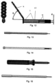
- Fig. 1b illustrates the type of damage to the glenoid socket caused by such dislocations.
- the pear-shape of the intact glenoid is shown at “A”; while bone loss at the inferior, wider section “A”, caused by a dislocation, is shown at “B” and results in an inverted pear shape narrower lower section as shown at "C”. This causes a partial loss of contact with the humeral head.
- Figs. 2a and 2b illustrate a bone reconstruction
- the description below describes a kit of instruments, and the method of their use, for performing coracoid transfer (Latarjet procedure) arthroscopically.
- the kit consists of various instruments, including drills, drill guides, osteotomes, cannulae, suture manipulators, screws, screwdrivers and others.
- the procedure consists of the following main steps:
- Figs. 2a and 2b 20 indicates the glenoid
- 21 illustrates the coracoid graft implanted thereto by a pair of cannulated devices 22 and 23
- 24 indicates the humeral head
- 25 indicates the conjoined tendon.
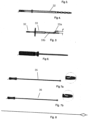
- Figs. 3-20 illustrate the various medical instruments, supplied , according to the invention, in kit form.
- portals small incisions
- the arthroscope and instruments are first made for introducing the arthroscope and instruments and for preparing the coracoid and glenoid surfaces, leaving the conjoined tendon (shown in Fig. 2b ) attached to the coracoid.
- Two threaded holes are drilled in the coracoid process, using the bone drill shown at 32 in Fig. 4 with a diameter of about 3 mm.
- a Kirschner wire 31 ( Fig. 3 ) is inserted at a safe distance from the lateral tip of the process for guiding the bone drill, and the first hole is drilled.
- the drill is inserted through the drill guide shown at 33 in Fig. 5 .
- a 33a fixed at distance "d" from the center of the drill nut 33b ensures a predetermined distance of about 9 mm from the first hole. Both holes are threaded now with the elongated tap shown at 34 in Fig. 6 . For safeguarding the integrity of the transplant, inserts may be implanted in the holes.
- a suture loader 35, Fig. 7a , and a suture retriever 36, in Fig. 7b are provided in the kit for manipulating the sutures.
- An alternative flexible wire 37 is shown in Fig. 8 .
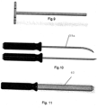
- the sutures/wires are drawn out through the shaft of a T-handle cannula shown at 38 in Fig. 9 and are fixed at the proximal, handle section of the cannula for holding the coracoid graft during separation and transfer to the receiving site.
- Osteotomes such as those shown at 39a, 39b in Fig. 10 , serve to separate the lateral section of the coracoid. At least one osteotome is provided in the kit.
- the subscapularis muscle is dissected and split to allow for transferring the T-handle cannula 38 with the coracoid transplant to the anterior-inferior, damaged section of the glenoid.
- the cannulator shown at 40 in Fig. 11 is used to dissect tissue and to free a passage to the receiving site.
- a double cannula shown at 41 in Fig. 12 is inserted through the passage freed by the cannulator.
- the two tubes “t” of the double cannula 41 are fixed, so that the distance of their centerlines “d” is identical to that of the drill guide 33 in Fig. 5 .
- Handle “h” attached to the tube is offset at an angle “a” relative to the axis of the tubes and is formed to provide a firm grip.
- Angle “a” should be of an order of 40 to 65 degrees to allow maneuvering without obstructing the field of vision, and the length of the tubes measured from the handle should be about 150mm.
- a window “w” is cut in each of the tubes near the distal end to enable observation of the interior of the two tubes, and the position of an instrument introduced into the tubes.
- the T-handle cannula 38 is released from the sutures/wires attached to the graft and is withdrawn.
- a suture hook shown at 42 in Fig. 13 the sutures/wires are drawn through the tubes of the double cannula and an elongated cannulated holding device such as screws 43 shown in Fig. 14 are inserted over them into the tubes of the cannula.
- the screws are driven into the coracoid using a suitable instrument, such as the screw driver shown at 44 in Fig. 15 until the coracoid is firmly attached to the cannula.
- FIG. 16 An alternative device for holding the separated coracoid bone transplant to the double cannula is shown at 45 in Fig. 16 .
- the distal section of the spike in Fig. 16 is expandable to hold the device to the walls of the bores of the graft.
- the sutures/wires holding the coracoid can now be removed.
- the exact positioning on the glenoid may be assisted by using a suitable instrument, such as the clamping device shown at 46 in Figs. 17a and 17b .
- Kirschner wires 31, Fig. 3
- the devices are now removed using the screwdriver 44, Fig. 15 , or by releasing the spike 45.
- the double cannula serves as a drill guide.
- a cannulated drill 47a, Fig. 18 inserted over one of the Kirschner wires, a first hole is drilled into the glenoid. Leaving the first drill in position, the other drill 47b in Fig. 18 , with the longer shaft, is used to drill a second hole over the second Kirschner wire.
- cannulated bone screws 48, Fig. 19 are inserted over the K-wires into the coracoid graft and are screwed part-way into the glenoid using the cannulated device driver with a long shaft 49, Fig. 20 , for use with the cannulated bone screws.
- the K-wires can now be pulled out and the optional bone clamping device is removed.
- the bone screws 48 are drawn tight and the double cannula is withdrawn to conclude the procedure.
Description
- The present invention relates to medical instruments useful in an arthroscopic bone transplanting procedure and to medical instruments useful in such a procedure as may be supplied in the form of a kit. The invention is particularly useful in the treatment of an anterior shoulder instability, where a section of the coracoid is transplanted to the glenoid, and is therefore described below with respect to said transplant.
- The range of movements the human shoulder can make far exceeds any other joint in the body. The shoulder joint is a ball and socket joint, similar to the hip; however, the socket of the shoulder joint is extremely shallow, and thus inherently unstable. Muscles and tendons serve to keep the bones in approximation. In addition, in order to compensate for the shallow socket, the shoulder joint has a cuff of fibrous cartilage called a labrum that forms a cup for the head of the arm bone (humerus) to move within. This cuff of cartilage makes the shoulder joint much more stable, yet allows for a very wide range of movement. When the labrum of the shoulder joint is damaged, the stability of the shoulder joint is compromised, leading to subluxation and dislocation of the joint. Recurrent dislocations may cause damage to the bones of the j oint -the humeral head and the glenoid. In particular, damage to the anterior-inferior part of the glenoid will cause a decrease in the area of contact with the humeral head.
- When bone deficiencies associated with anterior shoulder instability are present, the prognostic factors for the success of soft tissue repair are poor. Current standards of success are predicated on the restoration of motion and strength and the return to full functional activities, including competitive athletics. Reestablishment of anterior shoulder stability requires the recognition and the treatment of osseous defects.
- Several surgical procedures have been described for the management of osseous deficiencies in association with anterior shoulder instability, involving the transplantation of a portion of the coracoid process to the anterior-inferior section of the glenoid. The procedure described by Latarjet in 1954 involves the transplantation of a large section of the coracoid together with the conjoined tendon attached to it to reinforce the glenoid fossa and create an antero-inferior musculotendinous sling. The procedure has been performed since its disclosure with positive results as an open surgical intervention.
-
US 5,320,626 discloses "An endoscopic drill guide for locating the proper position of a graft tunnel for endosteal fixation of a substitute ligament or graft between two bones, such as a tibia and a femur. The drill guide includes a shaft with an offset hook. The drill guide is inserted through a graft tunnel drilled in the tibia, and the offset hook is positioned so that it engages the posterior aspect of the femoral notch. A guide pin is inserted through the drill guide and driven into the femur to properly position drilling of a graft tunnel in the femur" (abstract). -
EP 1,639,949 discloses "An instrument for preparing the glenoid surface of a shoulder joint to receive a prosthetic component having a feature closely conforming to the surface. The prosthetic component provides a bearing surface for a head portion of a humerus. The instrument includes a guide having a first feature and a second feature and a tool. The tool is used for cooperation with the first feature for preparing the surface. The first feature is adapted to control the position of the tool at least partially as it prepares the surface. The second feature is adapted to assist in positioning of the guide with respect to the j oint" (abstract). -
EP 1,430,844 discloses a "Centering aid comprises a dome-shaped cap placed on the bone head of a natural hip joint with a radial bore in a pole region and a further bore, a gage having a block-shaped structure with a number of bores and a stopping pin which can be placed in a bore in the bone head, and guiding pins for placing through the radial bore and through the bore of the gage. Preferred Features: The pole region of the cap is fixed to a bore reaching up to the pole region of the cap by a cylindrical bushing" (abstract). -
US 5 030 219 A illustrates drill guide for forming holes in the glenoid surface comprising an alignment peg insertable into a center hole formed in the glenoid and alignment holes to guide a drill bit. - However, up to the present, no minimally invasive technique for performing it has been developed.
- An object of the present invention is to a kit of medical instruments useful in an arthroscopic bone transplanting procedure which is particularly useful in the treatment of anterior shoulder instability, but may be used in other procedures involving implanting of a section of a first bone to a second bone.
- The medical kit of instruments according to the invention is defined in
claim 1. Preferred embodiments are defined in the dependent claims. The surgical methods disclosed do not form part of the claimed invention. - There are provided medical instruments for use in an arthroscopic procedure for transplanting a section of a first bone to a second bone, comprising the following steps: (a) making small incisions to open portals for the introduction of medical instruments; (b) drilling a threaded bore in said section of said first bone; (c) attaching a first cannula to said section of said first bone; (d) separating said section from said first bone; (e) positioning said separated section of said first bone on said second bone; (f) replacing said first cannula by a second cannula attached to said separated bone section by a cannulated device; (g) introducing a guide wire through the cannulated device; (h) removing the cannulated device; (i) drilling a bore into the second bone by a cannulated drill guided by said guide wire; (j) removing the guide wire; (k) and applying a bone screw through said bore in said separated section of the first bone and said bore in said second bone.
- The kit of the invention described below is particularly useful in a procedure for the treatment of anterior shoulder instability, or other disorders where it is desired to use at least two bone screws for attaching a section of a first bone to a second bone. When such a procedure is used, in step (b), two threaded bores at a fixed distance from each other are drilled in said section of the first bone; in step (c), the first cannula is a T-handle cannula and is attached in said first bore by sutures or flexible wires; in step (f), the second cannula is a double cannula and is attached to said section of the first bone by two cannulated devices; in step (g), two guide wires are introduced through the two cannulated devices, which cannulated devices are then removed in step (h); in step (i), two bores are drilled into the second bone by a cannulated drill guided by said guide wires; in step (j), the two guide wires are removed; and in step (k), two bone screws are applied through the two bones in the separated section of the first bone, and the two bores in the second bone.
- Further features of the invention will be apparent from the description below.
- The present invention is herein described below, the reference to the accompanying drawings, wherein:
-
Fig. 1a is a schematic drawing of the gleno-humeral j oint in the shoulder; -
Fig. 1b is a schematic lateral view illustrating damage to the glenoid fossa; -
Fig. 2a is a schematic anterior view of the bone reconstruction; -
Fig. 2b is a transverse section through the reconstructed joint, and -
Figs. 3-20 illustrate various medical instruments of the kit in accordance with the present invention, particularly useful in an arthroscopic bone transplanting procedure for reconstructing the shoulder joint, in which: -
Fig. 3 shows a standard Kirschner wire; -
Fig. 4 is a cannulated bone drill; -
Fig. 5 shows a drill guide for drilling a second bore at a predetermined distance from a first bore; -
Fig. 6 is a thread tapping tool; -
Fig. 7a is a suture loader; -
Fig. 7b is a suture retriever; -
Fig. 8 shows a flexible wire; -
Fig. 9 is a cannula with a T-handle; -
Fig. 10 shows osteotomes, straight and curved; -
Fig. 11 is a cannulator for a double cannula; -
Fig. 12 is a double cannula; -
Fig. 13 shows a suture hook; -
Fig. 14 shows a cannulated device -
Fig. 15 is a cannulated devicedriver; -
Fig. 16 is a cannulated spike; -
Figs. 17a and 17b are side and top views, respectively, of a clamping device for holding a transplanted bone section to the receiving site; -
Fig. 18 shows cannulated bone drills; -
Fig. 19 is a cannulated bone screw; and -
Fig. 20 is a screwdriver with a long cannulated shaft for the bone screws. -
Fig. 1a illustrates the bones of the shoulder j oint. Thehead 1 of the upper arm bone, thehumerus 2, forms a ball-and-socket joint with the shallowglenoid cavity 3. The glenoid is the lateral part of theshoulder blade scapula 4. Two hook-like projections of the scapula seen overhanging the glenoid are theacromion 5 and thecoracoid process 6. A group of muscles collectively know as the Rotator Cuff originate on the scapula and insert on the humerus. These serve to stabilize the joint by keeping the humeral head in contact with the glenoid cavity. Theclavicle 7 connects the acromion to the breastbone sternum. Theglenoid labrum 8, which is a flexible fibrous ligament, surrounds the glenoid rim enlarging its area of contact with the humerus. When dislocations in the direction shown by the arrow occur, the anterior-inferior part of the labrum is torn away from the glenoid, causing instability of the joint. Recurring dislocations may lead to osseous lesions. -
Fig. 1b illustrates the type of damage to the glenoid socket caused by such dislocations. The pear-shape of the intact glenoid is shown at "A"; while bone loss at the inferior, wider section "A", caused by a dislocation, is shown at "B" and results in an inverted pear shape narrower lower section as shown at "C". This causes a partial loss of contact with the humeral head. -
Figs. 2a and 2b illustrate a bone reconstruction. - The description below describes a kit of instruments, and the method of their use, for performing coracoid transfer (Latarjet procedure) arthroscopically. The kit consists of various instruments, including drills, drill guides, osteotomes, cannulae, suture manipulators, screws, screwdrivers and others.
- The procedure consists of the following main steps:
- Opening portals (small incisions); introducing the arthroscope and instruments
- Preparation of the coracoid and glenoid surfaces
- Drilling and threading two holes in the coracoid at a fixed distance
- Passing sutures or flexible wires through the holes
- Attaching the coracoid by sutures or flexible wires to a cannula
- Separating the section of the coracoid to be transferred
- Positioning the graft on the glenoid
- Attaching a double cannula to the coracoid with a cannulated device
- Introducing K-wires through the cannulated device
- Removing the cannulated device
- Drilling into the glenoid with a cannulated drill over the K-wires
- Attaching the transplanted coracoid onto the glenoid with bone screws
- Removing the K-wires
- Final fixing of the transplant (tightening the screws)
- Removing the cannula.
- In the reconstruction of the shoulder joint, utilizing medical kits according to the present invention, illustrated in
Figs. 2a and 2b , 20 indicates the glenoid, 21 illustrates the coracoid graft implanted thereto by a pair of cannulateddevices -
Figs. 3-20 illustrate the various medical instruments, supplied , according to the invention, in kit form. - According to the procedure, portals (small incisions) are first made for introducing the arthroscope and instruments and for preparing the coracoid and glenoid surfaces, leaving the conjoined tendon (shown in
Fig. 2b ) attached to the coracoid. Two threaded holes are drilled in the coracoid process, using the bone drill shown at 32 inFig. 4 with a diameter of about 3 mm. A Kirschner wire 31 (Fig. 3 ) is inserted at a safe distance from the lateral tip of the process for guiding the bone drill, and the first hole is drilled. For placing the second hole, the drill is inserted through the drill guide shown at 33 inFig. 5 . A 33a fixed at distance "d" from the center of thedrill nut 33b ensures a predetermined distance of about 9 mm from the first hole. Both holes are threaded now with the elongated tap shown at 34 inFig. 6 . For safeguarding the integrity of the transplant, inserts may be implanted in the holes. - Suture strands or flexible wires are now attached to the coracoid process for securing during separation by threading them through the holes. A
suture loader 35,Fig. 7a , and asuture retriever 36, inFig. 7b are provided in the kit for manipulating the sutures. An alternative flexible wire 37 is shown inFig. 8 . The sutures/wires are drawn out through the shaft of a T-handle cannula shown at 38 inFig. 9 and are fixed at the proximal, handle section of the cannula for holding the coracoid graft during separation and transfer to the receiving site. Osteotomes, such as those shown at 39a, 39b inFig. 10 , serve to separate the lateral section of the coracoid. At least one osteotome is provided in the kit. - Preparing for the transfer of the separated section of the coracoid, the subscapularis muscle is dissected and split to allow for transferring the T-handle cannula 38 with the coracoid transplant to the anterior-inferior, damaged section of the glenoid. The cannulator shown at 40 in
Fig. 11 is used to dissect tissue and to free a passage to the receiving site. A double cannula shown at 41 inFig. 12 is inserted through the passage freed by the cannulator. - The two tubes "t" of the
double cannula 41 are fixed, so that the distance of their centerlines "d" is identical to that of thedrill guide 33 inFig. 5 . Handle "h" attached to the tube is offset at an angle "a" relative to the axis of the tubes and is formed to provide a firm grip. Angle "a" should be of an order of 40 to 65 degrees to allow maneuvering without obstructing the field of vision, and the length of the tubes measured from the handle should be about 150mm. A window "w" is cut in each of the tubes near the distal end to enable observation of the interior of the two tubes, and the position of an instrument introduced into the tubes. - When the double cannula has been inserted to face the coracoid transplant, the T-handle cannula 38 is released from the sutures/wires attached to the graft and is withdrawn. Using a suture hook shown at 42 in
Fig. 13 , the sutures/wires are drawn through the tubes of the double cannula and an elongated cannulated holding device such as screws 43 shown inFig. 14 are inserted over them into the tubes of the cannula. The screws are driven into the coracoid using a suitable instrument, such as the screw driver shown at 44 inFig. 15 until the coracoid is firmly attached to the cannula. An alternative device for holding the separated coracoid bone transplant to the double cannula is shown at 45 inFig. 16 . The distal section of the spike inFig. 16 is expandable to hold the device to the walls of the bores of the graft. - The sutures/wires holding the coracoid can now be removed. The exact positioning on the glenoid may be assisted by using a suitable instrument, such as the clamping device shown at 46 in
Figs. 17a and 17b . Once the transplant is in the correct position on the glenoid, Kirschner wires (31,Fig. 3 ) are driven into the glenoid through the cannulated devices holding the coracoid. The devices are now removed using the screwdriver 44,Fig. 15 , or by releasing the spike 45. - The double cannula serves as a drill guide. With a cannulated drill 47a,
Fig. 18 , inserted over one of the Kirschner wires, a first hole is drilled into the glenoid. Leaving the first drill in position, the other drill 47b inFig. 18 , with the longer shaft, is used to drill a second hole over the second Kirschner wire. - After removing the drills, cannulated bone screws 48,
Fig. 19 , are inserted over the K-wires into the coracoid graft and are screwed part-way into the glenoid using the cannulated device driver with a long shaft 49,Fig. 20 , for use with the cannulated bone screws. - The K-wires can now be pulled out and the optional bone clamping device is removed. The bone screws 48 are drawn tight and the double cannula is withdrawn to conclude the procedure.
- While the invention has been described with respect to a preferred embodiment, it will be appreciated that this is set forth merely for purposes of example, and that many other variations, modifications and applications of the kit according to the invention may be made. Accordingly, the scope of the invention is defined by the appended claims.
Claims (10)
- A medical kit of instruments for transplanting a section of a first bone to a second bone in an arthroscopic procedure comprising:(a) a bone drill (32) for drilling a first bore and a second bore in the section;(b) an arthroscopic drill guide (33) for guiding drilling of the second bore a predetermined distance from a first bore formed in said section, comprising:a handle;an elongated shaft comprising a proximal end and a distal end, said proximal end coupled to said handle, said shaft configured to receive said bone drill (32);a drill nut (33b) at a distal portion of said drill guide (33), said drill nut defining an axis of said bone drill; anda guide pin (33a) positioned at a fixed predetermined distance (d) from said axis of said bone drill; said guide pin (33a) configured to fit within said first bore formed in said section; and(c) a double cannula (41) including:two tubes (t) extending parallel to each other; anda proximal end carrying a handle (h),wherein said two tubes have axes at said predetermined distance (d) allowing co-axial positioning of a first of the two tubes with said first bore when a second of the two tubes is coaxially aligned to said second bore for attaching said section to said second bone through said first bore and said second bore; andwherein each of said two tubes (t) has a distal end formed with a window (w) to enable observation of its interior.
- The medical kit according to claim 1, wherein said predetermined distance is 9 mm.
- The medical kit according to claim 1, wherein said handle of said arthroscopic drill guide (33) comprises a portion protruding perpendicularly from said elongated shaft.
- The medical kit according to claim 1, wherein said shaft is cylindrical.
- The medical kit according to claim 1, wherein said bone drill (32) is about 3 mm in diameter.
- The medical kit of any of claims 1 to 5, wherein said bone drill (32) is cannulated.
- The medical kit any one of claims 1 to 6, further comprising at least one curved osteotome (39a).
- The medical kit of any one of claims 1 to 7, , further comprising a cannulator (40) for dissecting tissue and freeing a passage to said second bone to permit the insertion of the double cannula (41).
- The medical kit of any one of claims 1 to 8, further comprising a suture retriever (36).
- The medical kit of any one of claims 1 to 9, wherein an axis of said handle (h) of said double cannula (41) is at an angle of 40-65 degrees to an axis of the two parallel tubes (t).
Applications Claiming Priority (3)
| Application Number | Priority Date | Filing Date | Title |
|---|---|---|---|
| US83417306P | 2006-07-31 | 2006-07-31 | |
| PCT/IL2007/000952 WO2008015670A2 (en) | 2006-07-31 | 2007-07-30 | Arthroscopic bone transplanting procedure, and medical instruments useful therein |
| EP07790007.4A EP2051642B1 (en) | 2006-07-31 | 2007-07-30 | Medical instruments useful for arthroscopic bone transplanting procedure |
Related Parent Applications (2)
| Application Number | Title | Priority Date | Filing Date |
|---|---|---|---|
| EP07790007.4A Division EP2051642B1 (en) | 2006-07-31 | 2007-07-30 | Medical instruments useful for arthroscopic bone transplanting procedure |
| PCT/IL2007/000952 Previously-Filed-Application WO2008015670A2 (en) | 2006-07-31 | 2007-07-30 | Arthroscopic bone transplanting procedure, and medical instruments useful therein |
Publications (2)
| Publication Number | Publication Date |
|---|---|
| EP3195817A1 EP3195817A1 (en) | 2017-07-26 |
| EP3195817B1 true EP3195817B1 (en) | 2023-09-06 |
Family
ID=38705113
Family Applications (2)
| Application Number | Title | Priority Date | Filing Date |
|---|---|---|---|
| EP16194921.9A Active EP3195817B1 (en) | 2006-07-31 | 2007-07-30 | Drill guide useful in arthroscopic bone transplanting procedure |
| EP07790007.4A Active EP2051642B1 (en) | 2006-07-31 | 2007-07-30 | Medical instruments useful for arthroscopic bone transplanting procedure |
Family Applications After (1)
| Application Number | Title | Priority Date | Filing Date |
|---|---|---|---|
| EP07790007.4A Active EP2051642B1 (en) | 2006-07-31 | 2007-07-30 | Medical instruments useful for arthroscopic bone transplanting procedure |
Country Status (6)
| Country | Link |
|---|---|
| US (3) | US8617219B2 (en) |
| EP (2) | EP3195817B1 (en) |
| JP (1) | JP5129816B2 (en) |
| AU (1) | AU2007280012B2 (en) |
| CA (2) | CA2660292C (en) |
| WO (1) | WO2008015670A2 (en) |
Families Citing this family (44)
| Publication number | Priority date | Publication date | Assignee | Title |
|---|---|---|---|---|
| JP4012733B2 (en) | 1999-09-20 | 2007-11-21 | フラクトゥス・ソシエダッド・アノニマ | Multi-level antenna |
| AU1046700A (en) | 1999-10-26 | 2001-05-08 | Fractus, S.A. | Interlaced multiband antenna arrays |
| BR0017065A (en) | 2000-01-19 | 2003-11-04 | Fractus Sa | Space Filling Antenna and Antenna Set |
| US9755314B2 (en) | 2001-10-16 | 2017-09-05 | Fractus S.A. | Loaded antenna |
| EP1436858A1 (en) | 2001-10-16 | 2004-07-14 | Fractus, S.A. | Multiband antenna |
| US6791500B2 (en) | 2002-12-12 | 2004-09-14 | Research In Motion Limited | Antenna with near-field radiation control |
| US8738103B2 (en) | 2006-07-18 | 2014-05-27 | Fractus, S.A. | Multiple-body-configuration multimedia and smartphone multifunction wireless devices |
| WO2008015670A2 (en) | 2006-07-31 | 2008-02-07 | T.A.G. Medical Products A Limited Partnership | Arthroscopic bone transplanting procedure, and medical instruments useful therein |
| WO2008146291A2 (en) | 2007-05-30 | 2008-12-04 | T.A.G. Medical Products A Limited Partnership | Piercing implement particularly useful as a medical implement for piercing body tissue, and method of using such implement for applying a suture to the body tissue |
| WO2009107121A2 (en) * | 2008-02-28 | 2009-09-03 | T.A.G. Medical Products Corportion Ltd. | Medical apparatus and method for attaching a suture to a bone |
| ATE500786T1 (en) * | 2008-06-20 | 2011-03-15 | Arthrex Inc | LATARJET INSTRUMENTATION |
| US9119644B2 (en) | 2010-08-21 | 2015-09-01 | New York Society For The Ruptured And Crippled Maintaining The Hospital For Special Surgery | Instruments for use in femoroacetabular impingement procedures |
| BE1019467A4 (en) * | 2010-09-02 | 2012-07-03 | Ceuster Marcel De | SURGICAL APPLICATION SYSTEM TO ENLARGE THE GLENOID WEAR SURFACE. |
| US9445857B2 (en) | 2011-07-21 | 2016-09-20 | Smith & Nephew, Inc. | Bone graft placement device |
| US9320557B2 (en) | 2011-07-21 | 2016-04-26 | Smith & Nephew, Inc. | Implant retaining loop and guide wire extension |
| BE1020248A4 (en) * | 2011-09-13 | 2013-07-02 | Ceuster Marcel De | SURGICAL APPLICATION SYSTEM TO ENLARGE THE GLENOID WEAR SURFACE: BLOCK. |
| US9782165B2 (en) | 2011-11-11 | 2017-10-10 | VentureMD Innovations, LLC | Transosseous attachment |
| US10675014B2 (en) | 2011-11-16 | 2020-06-09 | Crossroads Extremity Systems, Llc | Knotless soft tissue attachment |
| US10470756B2 (en) | 2011-11-16 | 2019-11-12 | VentureMD Innovations, LLC | Suture anchor and method |
| US10136883B2 (en) | 2011-11-16 | 2018-11-27 | VentureMD Innovations, LLC | Method of anchoring a suture |
| US10548585B2 (en) | 2011-11-16 | 2020-02-04 | VentureMD Innovations, LLC | Soft tissue attachment |
| US20130158610A1 (en) | 2011-12-16 | 2013-06-20 | Depuy Mitek, Inc. | Bone graft fixation systems and methods |
| EP2630935B1 (en) | 2012-02-27 | 2014-12-31 | Arthrex, Inc. | Glenoid extension block |
| US9668757B2 (en) | 2012-06-27 | 2017-06-06 | Arthrosurface, Inc. | Devices, apparatuses, kits, and methods for repair of articular surface and/or articular rim |
| US10350078B2 (en) * | 2012-06-27 | 2019-07-16 | Arthrosurface, Inc. | Devices, apparatuses, kits, and methods for repair of articular surface and/or articular rim |
| US9687221B2 (en) | 2013-02-13 | 2017-06-27 | Venture MD Innovations, LLC | Method of anchoring a suture |
| US10751161B2 (en) | 2014-10-23 | 2020-08-25 | Medos International Sárl | Biceps tenodesis anchor implants |
| US10034742B2 (en) | 2014-10-23 | 2018-07-31 | Medos International Sarl | Biceps tenodesis implants and delivery tools |
| US10729419B2 (en) | 2014-10-23 | 2020-08-04 | Medos International Sarl | Biceps tenodesis implants and delivery tools |
| US10076374B2 (en) | 2014-10-23 | 2018-09-18 | Medos International Sárl | Biceps tenodesis delivery tools |
| US10856966B2 (en) | 2014-10-23 | 2020-12-08 | Medos International Sarl | Biceps tenodesis implants and delivery tools |
| US10806472B2 (en) * | 2015-03-10 | 2020-10-20 | Smith & Nephew, Inc. | Open Latarjet for correction of anterior-inferior glenoid bone loss |
| US9693856B2 (en) | 2015-04-22 | 2017-07-04 | DePuy Synthes Products, LLC | Biceps repair device |
| US10820918B2 (en) | 2015-07-17 | 2020-11-03 | Crossroads Extremity Systems, Llc | Transosseous guide and method |
| US10154868B2 (en) | 2015-07-17 | 2018-12-18 | Kator, Llc | Transosseous method |
| US9962174B2 (en) | 2015-07-17 | 2018-05-08 | Kator, Llc | Transosseous method |
| US10226243B2 (en) | 2015-08-04 | 2019-03-12 | Kator, Llc | Transosseous suture anchor |
| US9918769B2 (en) | 2015-08-28 | 2018-03-20 | Arthrex, Inc. | Instrumentation and technique for sizing a bone reconstruction graft |
| US10327789B2 (en) | 2015-12-29 | 2019-06-25 | Medos International Sarl | Methods and systems for preparing bone for a surgical procedure |
| US10231823B2 (en) | 2016-04-08 | 2019-03-19 | Medos International Sarl | Tenodesis implants and tools |
| US10231824B2 (en) | 2016-04-08 | 2019-03-19 | Medos International Sárl | Tenodesis anchoring systems and tools |
| US11331091B2 (en) * | 2017-11-14 | 2022-05-17 | Endovision Co., Ltd. | Surgical instrument set for use during unilateral biportal endoscopy |
| US11213406B2 (en) | 2019-07-10 | 2022-01-04 | Arthrex, Inc. | Graft preparation station for repairing bone defects |
| EP4179984A1 (en) * | 2020-07-08 | 2023-05-17 | National University Corporation Shiga University Of Medical Science | Surgical instrument, medical tool set, and movement method |
Family Cites Families (42)
| Publication number | Priority date | Publication date | Assignee | Title |
|---|---|---|---|---|
| US4381770A (en) * | 1981-10-26 | 1983-05-03 | Neufeld Alonzo J | Method and apparatus for performing percutaneous bone surgery and new pin implant |
| FR2560764B1 (en) * | 1984-03-09 | 1988-05-13 | Matco | DAVIER FOR FRACTURE REDUCTION |
| US4860735A (en) * | 1988-08-08 | 1989-08-29 | The General Hospital Corporation | Drill alignment guide for osteoplastic surgery |
| US5030219A (en) * | 1990-01-22 | 1991-07-09 | Boehringer Mannheim Corporation | Glenoid component installation tools |
| GB9016205D0 (en) * | 1990-07-24 | 1990-09-05 | Chadwick Christopher J | Interlocking intramedullary nails |
| US5395317A (en) * | 1991-10-30 | 1995-03-07 | Smith & Nephew Dyonics, Inc. | Unilateral biportal percutaneous surgical procedure |
| US5520693A (en) * | 1992-02-19 | 1996-05-28 | Mcguire; David A. | Femoral guide and methods of precisely forming bone tunnels in cruciate ligament reconstruction of the knee |
| US5320626A (en) * | 1992-02-19 | 1994-06-14 | Arthrex Inc. | Endoscopic drill guide |
| US5637112A (en) * | 1992-06-08 | 1997-06-10 | Orthopedic Systems, Inc. | Apparatus for attaching suture to bone |
| JP3532622B2 (en) * | 1993-03-28 | 2004-05-31 | ゴットフリード イェチエル | Surgical instruments for percutaneous connection |
| IL109929A (en) | 1994-06-08 | 1998-04-05 | Gotfried Yehiel | Surgical instrument for use during connection of a fractured bone |
| US5527322A (en) | 1993-11-08 | 1996-06-18 | Perclose, Inc. | Device and method for suturing of internal puncture sites |
| WO1995020362A1 (en) * | 1994-01-26 | 1995-08-03 | Reiley Mark A | Improved inflatable device for use in surgical protocol relating to fixation of bone |
| US5697932A (en) | 1994-11-09 | 1997-12-16 | Osteonics Corp. | Bone graft delivery system and method |
| SE506404C2 (en) | 1994-11-22 | 1997-12-15 | Lars Johan Henrik Hansson | Control instruments intended for fixing bone fragments in case of bone fracture |
| US5584839A (en) * | 1994-12-12 | 1996-12-17 | Gieringer; Robert E. | Intraarticular drill guide and arthroscopic methods |
| US5562686A (en) | 1995-04-19 | 1996-10-08 | United States Surgical Corporation | Apparaus and method for suturing body tissue |
| JPH0975366A (en) | 1995-09-12 | 1997-03-25 | M Ii Syst:Kk | Guide for drilling collum femoris part |
| RU2087133C1 (en) | 1996-01-11 | 1997-08-20 | Гуськов Игорь Алексеевич | Method for treating femoral neck fractures |
| JP3611934B2 (en) * | 1996-10-23 | 2005-01-19 | メイラ株式会社 | Bone drilling device for ligament reconstruction |
| US5993466A (en) | 1997-06-17 | 1999-11-30 | Yoon; Inbae | Suturing instrument with multiple rotatably mounted spreadable needle holders |
| CA2238117C (en) | 1997-05-30 | 2006-01-10 | United States Surgical Corporation | Method and instrumentation for implant insertion |
| DE29805703U1 (en) | 1998-03-28 | 1998-08-27 | Brehm Peter | Bone grasping forceps |
| US6197033B1 (en) * | 1998-04-09 | 2001-03-06 | Sdgi Holdings, Inc. | Guide sleeve for offset vertebrae |
| EP1069864B1 (en) | 1998-04-09 | 2004-09-01 | SDGI Holdings, Inc. | Vertebral body distraction device |
| US6635739B2 (en) * | 1999-10-15 | 2003-10-21 | Theresa Siler-Khodr | Non-mammalian GnRH analogs and uses thereof in regulation of fertility and pregnancy |
| US6656189B1 (en) * | 2000-05-25 | 2003-12-02 | Synthes (Usa) | Radiolucent aiming guide |
| JP2002102236A (en) | 2000-10-02 | 2002-04-09 | Koseki Ika Kk | Drill guide for patella |
| KR100889416B1 (en) * | 2000-10-25 | 2009-03-20 | 키폰 에스에이알엘 | Systems and methods for reducing fractured bone using a fracture reduction cannula |
| US6511487B1 (en) | 2000-11-28 | 2003-01-28 | T. A. G. Medical Products Ltd. | Suturing instrument and method |
| US6679888B2 (en) * | 2001-05-29 | 2004-01-20 | Synthes | Femur lever |
| DE10261813B4 (en) * | 2002-12-19 | 2004-10-28 | Eska Implants Gmbh & Co. | Centering aid for a joint head cap implant of an artificial hip joint |
| US7326216B2 (en) * | 2003-04-02 | 2008-02-05 | Warsaw Orthopedic, Inc. | Methods and instrumentation for positioning implants in spinal disc space in an anterior lateral approach |
| WO2005053548A1 (en) | 2003-12-03 | 2005-06-16 | Synthes Ag Chur | Device for repositioning bone fractures |
| JP2006006817A (en) * | 2004-06-29 | 2006-01-12 | Canon Star Kk | Intraocular lens insertion instrument |
| US7927335B2 (en) * | 2004-09-27 | 2011-04-19 | Depuy Products, Inc. | Instrument for preparing an implant support surface and associated method |
| EP1683487B1 (en) | 2005-01-24 | 2008-02-27 | AMI Agency for Medical Innovations GmbH | Device for closing a trocar puncture wound |
| US20070005067A1 (en) | 2005-06-21 | 2007-01-04 | Brian Dross | Arthoscopic method and apparatus for tissue attachment to bone |
| US20070073342A1 (en) | 2005-09-27 | 2007-03-29 | Innovative Spinal Technologies | Annular access device using t-anchors |
| US8574239B2 (en) * | 2005-09-28 | 2013-11-05 | Hoya Corporation | Intraocular lens insertion device |
| WO2008015670A2 (en) | 2006-07-31 | 2008-02-07 | T.A.G. Medical Products A Limited Partnership | Arthroscopic bone transplanting procedure, and medical instruments useful therein |
| WO2008146291A2 (en) | 2007-05-30 | 2008-12-04 | T.A.G. Medical Products A Limited Partnership | Piercing implement particularly useful as a medical implement for piercing body tissue, and method of using such implement for applying a suture to the body tissue |
-
2007
- 2007-07-30 WO PCT/IL2007/000952 patent/WO2008015670A2/en active Application Filing
- 2007-07-30 EP EP16194921.9A patent/EP3195817B1/en active Active
- 2007-07-30 US US12/375,422 patent/US8617219B2/en active Active
- 2007-07-30 CA CA2660292A patent/CA2660292C/en active Active
- 2007-07-30 AU AU2007280012A patent/AU2007280012B2/en active Active
- 2007-07-30 EP EP07790007.4A patent/EP2051642B1/en active Active
- 2007-07-30 CA CA2916476A patent/CA2916476C/en active Active
- 2007-07-30 JP JP2009522415A patent/JP5129816B2/en active Active
-
2013
- 2013-12-30 US US14/142,971 patent/US9220513B2/en active Active
-
2015
- 2015-11-11 US US14/937,908 patent/US20160058456A1/en not_active Abandoned
Also Published As
| Publication number | Publication date |
|---|---|
| US20100069974A1 (en) | 2010-03-18 |
| WO2008015670A2 (en) | 2008-02-07 |
| US20140114317A1 (en) | 2014-04-24 |
| WO2008015670A3 (en) | 2008-06-19 |
| EP2051642A2 (en) | 2009-04-29 |
| WO2008015670A9 (en) | 2008-10-16 |
| US8617219B2 (en) | 2013-12-31 |
| JP5129816B2 (en) | 2013-01-30 |
| EP2051642B1 (en) | 2016-11-16 |
| EP3195817A1 (en) | 2017-07-26 |
| AU2007280012B2 (en) | 2013-01-31 |
| CA2916476A1 (en) | 2008-02-07 |
| CA2660292A1 (en) | 2008-02-07 |
| US20160058456A1 (en) | 2016-03-03 |
| CA2916476C (en) | 2018-11-13 |
| JP2009545364A (en) | 2009-12-24 |
| CA2660292C (en) | 2016-03-08 |
| US9220513B2 (en) | 2015-12-29 |
| AU2007280012A1 (en) | 2008-02-07 |
Similar Documents
| Publication | Publication Date | Title |
|---|---|---|
| EP3195817B1 (en) | Drill guide useful in arthroscopic bone transplanting procedure | |
| US11344323B2 (en) | Methods and systems for preparing bone for a surgical procedure | |
| US8840619B2 (en) | Dovetail method of allograft transplantation | |
| JP2023162360A (en) | Implantable glenoid components | |
| CN110115611A (en) | A kind of operation tool for caput femoris necrosis bone grafting | |
| US20230329873A1 (en) | Hip joint device and method | |
| AU2019286808B2 (en) | Hip or shoulder prosthesis and positioning instrument | |
| AU2013205475B2 (en) | Arthroscopic Bone Transplanting Procedure, and Medical Instruments Useful Therein | |
| AU2017202188B2 (en) | Arthroscopic Bone Transplanting Procedure, and Medical Instruments Useful Therein | |
| US11298245B2 (en) | Method for surgical application of a glenoid prosthesis component of a shoulder joint prosthesis and relating surgical instruments | |
| EP3395297B1 (en) | Osteochondral local prosthetic insert | |
| US20120150315A1 (en) | Hip joint device and method | |
| Lajtai et al. | Arthroscopic Reconstruction of Glenoid Fractures | |
| Cofield | CHAPTER AT A GLANCE INTRODUCTION 131 SURGICAL ANATOMY 132 EVALUATION 132 SURGICAL INDICATIONS 132 |
Legal Events
| Date | Code | Title | Description |
|---|---|---|---|
| PUAI | Public reference made under article 153(3) epc to a published international application that has entered the european phase |
Free format text: ORIGINAL CODE: 0009012 |
|
| STAA | Information on the status of an ep patent application or granted ep patent |
Free format text: STATUS: REQUEST FOR EXAMINATION WAS MADE |
|
| 17P | Request for examination filed |
Effective date: 20161020 |
|
| AC | Divisional application: reference to earlier application |
Ref document number: 2051642 Country of ref document: EP Kind code of ref document: P |
|
| AK | Designated contracting states |
Kind code of ref document: A1 Designated state(s): AT BE BG CH CY CZ DE DK EE ES FI FR GB GR HU IE IS IT LI LT LU LV MC MT NL PL PT RO SE SI SK TR |
|
| STAA | Information on the status of an ep patent application or granted ep patent |
Free format text: STATUS: EXAMINATION IS IN PROGRESS |
|
| 17Q | First examination report despatched |
Effective date: 20200702 |
|
| STAA | Information on the status of an ep patent application or granted ep patent |
Free format text: STATUS: EXAMINATION IS IN PROGRESS |
|
| GRAP | Despatch of communication of intention to grant a patent |
Free format text: ORIGINAL CODE: EPIDOSNIGR1 |
|
| STAA | Information on the status of an ep patent application or granted ep patent |
Free format text: STATUS: GRANT OF PATENT IS INTENDED |
|
| INTG | Intention to grant announced |
Effective date: 20221209 |
|
| GRAS | Grant fee paid |
Free format text: ORIGINAL CODE: EPIDOSNIGR3 |
|
| P01 | Opt-out of the competence of the unified patent court (upc) registered |
Effective date: 20230602 |
|
| GRAA | (expected) grant |
Free format text: ORIGINAL CODE: 0009210 |
|
| STAA | Information on the status of an ep patent application or granted ep patent |
Free format text: STATUS: THE PATENT HAS BEEN GRANTED |
|
| RAP1 | Party data changed (applicant data changed or rights of an application transferred) |
Owner name: T.A.G. MEDICAL PRODUCTS CORPORATION LTD. |
|
| AC | Divisional application: reference to earlier application |
Ref document number: 2051642 Country of ref document: EP Kind code of ref document: P |
|
| AK | Designated contracting states |
Kind code of ref document: B1 Designated state(s): AT BE BG CH CY CZ DE DK EE ES FI FR GB GR HU IE IS IT LI LT LU LV MC MT NL PL PT RO SE SI SK TR |
|
| REG | Reference to a national code |
Ref country code: GB Ref legal event code: FG4D |
|
| REG | Reference to a national code |
Ref country code: CH Ref legal event code: EP |
|
| REG | Reference to a national code |
Ref country code: IE Ref legal event code: FG4D |
|
| REG | Reference to a national code |
Ref country code: DE Ref legal event code: R096 Ref document number: 602007061752 Country of ref document: DE |
|
| REG | Reference to a national code |
Ref country code: LT Ref legal event code: MG9D |
|
| REG | Reference to a national code |
Ref country code: NL Ref legal event code: MP Effective date: 20230906 |
|
| PG25 | Lapsed in a contracting state [announced via postgrant information from national office to epo] |
Ref country code: GR Free format text: LAPSE BECAUSE OF FAILURE TO SUBMIT A TRANSLATION OF THE DESCRIPTION OR TO PAY THE FEE WITHIN THE PRESCRIBED TIME-LIMIT Effective date: 20231207 |
|
| PG25 | Lapsed in a contracting state [announced via postgrant information from national office to epo] |
Ref country code: SE Free format text: LAPSE BECAUSE OF FAILURE TO SUBMIT A TRANSLATION OF THE DESCRIPTION OR TO PAY THE FEE WITHIN THE PRESCRIBED TIME-LIMIT Effective date: 20230906 Ref country code: LV Free format text: LAPSE BECAUSE OF FAILURE TO SUBMIT A TRANSLATION OF THE DESCRIPTION OR TO PAY THE FEE WITHIN THE PRESCRIBED TIME-LIMIT Effective date: 20230906 Ref country code: LT Free format text: LAPSE BECAUSE OF FAILURE TO SUBMIT A TRANSLATION OF THE DESCRIPTION OR TO PAY THE FEE WITHIN THE PRESCRIBED TIME-LIMIT Effective date: 20230906 Ref country code: GR Free format text: LAPSE BECAUSE OF FAILURE TO SUBMIT A TRANSLATION OF THE DESCRIPTION OR TO PAY THE FEE WITHIN THE PRESCRIBED TIME-LIMIT Effective date: 20231207 Ref country code: FI Free format text: LAPSE BECAUSE OF FAILURE TO SUBMIT A TRANSLATION OF THE DESCRIPTION OR TO PAY THE FEE WITHIN THE PRESCRIBED TIME-LIMIT Effective date: 20230906 |
|
| REG | Reference to a national code |
Ref country code: AT Ref legal event code: MK05 Ref document number: 1607446 Country of ref document: AT Kind code of ref document: T Effective date: 20230906 |
|
| PG25 | Lapsed in a contracting state [announced via postgrant information from national office to epo] |
Ref country code: NL Free format text: LAPSE BECAUSE OF FAILURE TO SUBMIT A TRANSLATION OF THE DESCRIPTION OR TO PAY THE FEE WITHIN THE PRESCRIBED TIME-LIMIT Effective date: 20230906 |
|
| PG25 | Lapsed in a contracting state [announced via postgrant information from national office to epo] |
Ref country code: IS Free format text: LAPSE BECAUSE OF FAILURE TO SUBMIT A TRANSLATION OF THE DESCRIPTION OR TO PAY THE FEE WITHIN THE PRESCRIBED TIME-LIMIT Effective date: 20240106 |