JP2017192567A - Infusion pump - Google Patents

Infusion pump Download PDF

Info

Publication number
JP2017192567A
JP2017192567A JP2016084708A JP2016084708A JP2017192567A JP 2017192567 A JP2017192567 A JP 2017192567A JP 2016084708 A JP2016084708 A JP 2016084708A JP 2016084708 A JP2016084708 A JP 2016084708A JP 2017192567 A JP2017192567 A JP 2017192567A
Authority
JP
Japan
Prior art keywords
infusion
tube
door
pump
finger
Prior art date
Legal status (The legal status is an assumption and is not a legal conclusion. Google has not performed a legal analysis and makes no representation as to the accuracy of the status listed.)
Granted
Application number
JP2016084708A
Other languages
Japanese (ja)
Other versions
JP6825224B2 (en
Inventor
良一 赤井
Ryoichi AKAI
良一 赤井
高橋 秀典
Shusuke Takahashi
秀典 高橋
Current Assignee (The listed assignees may be inaccurate. Google has not performed a legal analysis and makes no representation or warranty as to the accuracy of the list.)
Nipro Corp
Original Assignee
Nipro Corp
Priority date (The priority date is an assumption and is not a legal conclusion. Google has not performed a legal analysis and makes no representation as to the accuracy of the date listed.)
Filing date
Publication date
Application filed by Nipro Corp filed Critical Nipro Corp
Priority to JP2016084708A priority Critical patent/JP6825224B2/en
Publication of JP2017192567A publication Critical patent/JP2017192567A/en
Application granted granted Critical
Publication of JP6825224B2 publication Critical patent/JP6825224B2/en
Active legal-status Critical Current
Anticipated expiration legal-status Critical

Links

Images

Landscapes

  • Reciprocating Pumps (AREA)
  • Infusion, Injection, And Reservoir Apparatuses (AREA)

Abstract

PROBLEM TO BE SOLVED: To provide an infusion pump capable of securing accuracy of a flow rate of infusion.SOLUTION: The infusion pump includes presser plates 61 and 71 at positions respectively in an upstream side and a downstream side of an infusion feed direction of a backing plate 5 (a pump-part tube groove) in the inside of a door 12. When the door 12 is in an open state, tube pressing surfaces 61a and 71a of the respective presser plates project further than the tube backing surface 51a of the backing plate 5 by elastic force of springs, and are configured to come into contact with an infusion tube T in a step where the door 12 is closed from the open state, before the tube backing surface 51a of the backing plate 5 comes into contact therewith. This configuration is less prone to bend the infusion tube T in the pump-part tube groove in a state where the door 12 is closed, so as to secure accuracy of the flow rate of the infusion.SELECTED DRAWING: Figure 12

Description

本発明は、医療用の薬液を体内に注入する場合などに用いる輸液ポンプに関する。   The present invention relates to an infusion pump used for injecting a medical solution into a body.

輸液ポンプとしては、フィンガ式(ペリスタルティック式)の輸液ポンプがある。フィンガ式の輸液ポンプは、例えば、フィンガと受け板との間に、輸液バッグに接続された輸液チューブを配置した状態で、フィンガを輸液チューブに対して進退駆動させ、フィンガにて輸液チューブを押圧することにより輸液を送り出す方式の輸液ポンプである。   As an infusion pump, there is a finger type (peristaltic type) infusion pump. The finger-type infusion pump, for example, drives the finger forward and backward with respect to the infusion tube with the infusion tube connected to the infusion bag between the finger and the receiving plate, and presses the infusion tube with the finger. This is an infusion pump that delivers the infusion by doing so.

フィンガ式の輸液ポンプとしては、フィンガで輸液チューブを完全に圧閉する方式(フルプレス方式)の輸液ポンプがある。また、フィンガで輸液チューブを完全に圧閉しない中間圧閉方式(半閉塞方式)の輸液ポンプが提案されている(例えば、特許文献1及び2参照)。半閉塞方式の輸液ポンプは、例えば、図14に示すように、輸液チューブTを完全につぶさずに送液を行う複数(3本)の送液フィンガ521・・521、及び、この送液フィンガの輸液送り方向(フィンガ配列方向:Y方向)の上流側と下流側にそれぞれ配置され、輸液チューブTの完全圧閉と開放とを行う閉塞フィンガ531,531などを備えている。なお、図14には、輸液ポンプのポンプ機構502のみを示している。   As a finger type infusion pump, there is an infusion pump of a system (full press system) in which an infusion tube is completely closed with a finger. Further, an infusion pump of an intermediate pressure closing method (semi-occlusion method) in which an infusion tube is not completely closed with a finger has been proposed (see, for example, Patent Documents 1 and 2). For example, as shown in FIG. 14, the semi-occluded infusion pump includes a plurality (three) of liquid feeding fingers 521... 521 that perform liquid feeding without completely crushing the infusion tube T, and the liquid feeding fingers. Are provided on the upstream side and the downstream side of the infusion feeding direction (finger arrangement direction: Y direction), respectively, and include closed fingers 531 and 531 for completely closing and opening the infusion tube T. FIG. 14 shows only the pump mechanism 502 of the infusion pump.

図14に示す輸液ポンプにおいては、ポンプ機構502の送液フィンガ521・・521及び閉塞フィンガ531,531はフィンガホルダ504に配置されている。フィンガホルダ504の前面壁540にはポンプ部チューブ溝541が設けられている。ポンプ部チューブ溝541は輸液送り方向(Y方向)に延びる矩形スリット状に形成されており、このポンプ部チューブ溝541に、送液フィンガ521・・521及び閉塞フィンガ531,531の各先端部が臨んでいる。一方、図示はしないが、輸液ポンプの扉の内側(内壁)には、当該扉を閉鎖した状態で上記ポンプ部チューブ溝541内に入り込む凸部を有する受け板が設けられている。   In the infusion pump shown in FIG. 14, the liquid feeding fingers 521... 521 and the closing fingers 531, 531 of the pump mechanism 502 are arranged in the finger holder 504. A pump portion tube groove 541 is provided in the front wall 540 of the finger holder 504. The pump portion tube groove 541 is formed in a rectangular slit shape extending in the infusion feeding direction (Y direction), and the tip portions of the liquid feeding fingers 521... 521 and the closing fingers 531 and 531 are formed in the pump portion tube groove 541. I'm here. On the other hand, although not shown, a receiving plate having a convex portion that enters the pump portion tube groove 541 in a state where the door is closed is provided on the inner side (inner wall) of the infusion pump.

そして、図14に示す輸液ポンプでは、ポンプ部チューブ溝541に輸液チューブTを配置した状態で扉を閉鎖することにより、送液フィンガ521・・521及び閉塞フィンガ531,531の各先端と受け板の凸部の先端(チューブ受け面)との間に輸液チューブTが配置され、この状態で、送液フィンガ521・・521及び閉塞フィンガ531,531をそれぞれ個別に駆動することにより輸液チューブT内の輸液を送液することができる。   In the infusion pump shown in FIG. 14, the tips of the liquid feeding fingers 521... 521 and the closing fingers 531 and 531 and the receiving plate are closed by closing the door in a state where the infusion tube T is arranged in the pump portion tube groove 541. The infusion tube T is disposed between the tip of the convex portion (tube receiving surface), and in this state, the infusion tube T is driven by individually driving the infusion fingers 521. Can be delivered.

特許第3595136号公報Japanese Patent No. 3595136 特開昭55−005485号公報JP 55-005485 A

ところで、上記した輸液ポンプでは、扉を閉鎖した状態で、ポンプ部チューブ溝541内において輸液チューブTが直線状に配置されている場合には問題はない。   By the way, in the above-mentioned infusion pump, there is no problem when the infusion tube T is linearly arranged in the pump portion tube groove 541 with the door closed.

しかしながら、扉を閉じる過程において、何らかの理由により輸液チューブTが動いてしまい、図15に示すように、輸液チューブTの一部が曲がる可能性がある。このようにポンプ部チューブ溝541内において輸液チューブTが曲がった状態になると、輸液チューブTが輸液ポンプに挟み込まれてしまう可能性があり、輸液の流量精度が低下するおそれがある。   However, in the process of closing the door, the infusion tube T moves for some reason, and there is a possibility that a part of the infusion tube T bends as shown in FIG. When the infusion tube T is bent in the pump portion tube groove 541 as described above, the infusion tube T may be sandwiched between the infusion pumps, and the flow rate accuracy of the infusion solution may be reduced.

本発明は、このような実情を考慮してなされたもので、輸液の流量精度を確保することが可能な輸液ポンプを提供することを目的とする。   The present invention has been made in consideration of such a situation, and an object thereof is to provide an infusion pump capable of ensuring the accuracy of the infusion flow rate.

本発明は、輸液チューブを押圧する複数のフィンガを備えたポンプ機構とポンプ部チューブ溝とを有するポンプ本体と、前記ポンプ本体の輸液チューブ取付位置を開閉自在に覆う扉と、前記扉の内側(内壁)に設けられ、当該扉を閉鎖した状態で前記複数のフィンガの先端部に対向して配置される受け板とを備え、前記ポンプ部チューブ溝に輸液チューブを配置し、前記扉を閉鎖した状態で、前記各フィンガを前記輸液チューブに対して進退駆動することにより当該輸液チューブ内の輸液を送液する輸液ポンプを前提としている。   The present invention includes a pump body having a pump mechanism having a plurality of fingers for pressing an infusion tube and a pump section tube groove, a door that covers the infusion tube mounting position of the pump body in an openable and closable manner, and an inner side of the door ( And a receiving plate that is disposed to face the front ends of the plurality of fingers in a state where the door is closed, an infusion tube is disposed in the pump portion tube groove, and the door is closed. In this state, it is premised on an infusion pump that feeds the infusion in the infusion tube by driving the fingers forward and backward with respect to the infusion tube.

このような輸液ポンプにおいて、前記扉の内側であって前記受け板(ポンプ部チューブ溝)の輸液送り方向の上流側と下流側となる位置に、それぞれ、前記扉(ポンプ本体)に対して接近離反する方向に移動可能な押え板が設けられている。そして、前記各押え板のチューブ押え面は、前記扉が開放状態のときには、ばねの弾性力によって前記受け板のチューブ受け面よりも前記扉から離れる側に突出しており、前記扉が開放状態から閉じられる過程において、前記受け板のチューブ受け面よりも先に前記輸液チューブに当接するように構成されていることを特徴としている。   In such an infusion pump, the position close to the door (pump main body) is located inside the door and on the upstream side and the downstream side of the receiving plate (pump portion tube groove) in the infusion feeding direction. A presser plate that can move in the direction of separating is provided. And when the door is in the open state, the tube pressing surface of each pressing plate protrudes to the side away from the door from the tube receiving surface of the receiving plate by the elastic force of the spring, and the door is in the open state. In the process of being closed, it is configured to contact the infusion tube before the tube receiving surface of the receiving plate.

本発明によれば、扉を開放状態から閉じる過程において、上流側の押え板のチューブ押え面及び下流側の押え板のチューブ押え面が、受け板のチューブ受け面よりも先に輸液チューブに当接する。これにより、ポンプ部チューブ溝の上流側の輸液チューブ及び下流側の輸液チューブの上下方向及び左右方向の位置が固定されるので、扉を閉鎖した状態において、ポンプ部チューブ溝内の輸液チューブに曲がりが生じにくくなる。これによって輸液の流量精度を確保することが可能になる。   According to the present invention, in the process of closing the door from the open state, the tube pressing surface of the upstream pressing plate and the tube pressing surface of the downstream pressing plate contact the infusion tube before the tube receiving surface of the receiving plate. Touch. As a result, the vertical and horizontal positions of the infusion tube on the upstream side and the infusion tube on the downstream side of the pump portion tube groove are fixed, so that the infusion tube in the pump portion tube groove is bent when the door is closed Is less likely to occur. This makes it possible to ensure the flow rate accuracy of the infusion.

本発明によれば、ポンプ部チューブ溝内において輸液チューブに曲がりが生じにくくなるので、輸液の流量精度を確保することが可能になる。   According to the present invention, since the infusion tube is less likely to bend in the pump portion tube groove, it is possible to ensure the flow rate accuracy of the infusion.

本発明を適用する輸液ポンプの概略構成図である。この図1では輸液ポンプの扉を開いた状態を示している。It is a schematic block diagram of the infusion pump to which this invention is applied. FIG. 1 shows a state where the door of the infusion pump is opened. ポンプ機構の正面図である。It is a front view of a pump mechanism. フィンガホルダの前面壁及び受け板の構成を示す断面図である。It is sectional drawing which shows the structure of the front wall of a finger holder, and a receiving plate. ポンプ機構の構成を示す部分断面側面図である。It is a fragmentary sectional side view which shows the structure of a pump mechanism. ポンプ機構の駆動部の構成を模式的に示す図である。It is a figure which shows typically the structure of the drive part of a pump mechanism. 図4に示すポンプ機構の動作説明図である。It is operation | movement explanatory drawing of the pump mechanism shown in FIG. 図4に示すポンプ機構の動作説明図である。It is operation | movement explanatory drawing of the pump mechanism shown in FIG. 図4に示すポンプ機構の動作説明図である。It is operation | movement explanatory drawing of the pump mechanism shown in FIG. 受け板及び押え機構の構成を示す断面図である。It is sectional drawing which shows the structure of a receiving plate and a pressing mechanism. 上流側の押え機構の構成を示す断面図である。It is sectional drawing which shows the structure of the holding mechanism of an upstream. 下流側の押え機構の構成を示す断面図である。It is sectional drawing which shows the structure of the downstream pressing mechanism. 扉を閉じる過程において押え板のチューブ押え面が輸液チューブに当接した状態を示す断面図である。It is sectional drawing which shows the state which the tube pressing surface of the pressing plate contacted the infusion tube in the process of closing a door. 扉を閉鎖した状態での受け板のチューブ受け面と押え板のチューブ押え面との位置を示す断面図である。It is sectional drawing which shows the position of the tube receiving surface of a receiving plate in the state which closed the door, and the tube pressing surface of a pressing plate. 輸液ポンプの一例を示す図である。なお、図14にはポンプ機構のみを示している。It is a figure which shows an example of an infusion pump. FIG. 14 shows only the pump mechanism. ポンプ部チューブ溝内において輸液チューブが曲がっている状態を示す図である。It is a figure which shows the state in which the infusion tube is bent in the pump part tube groove | channel.

以下、本発明の実施形態を図面に基づいて説明する。   Hereinafter, embodiments of the present invention will be described with reference to the drawings.

本発明を適用する輸液ポンプの一例について図1〜図8を参照して説明する。   An example of an infusion pump to which the present invention is applied will be described with reference to FIGS.

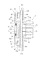
この例の輸液ポンプ1は、半閉塞方式の輸液ポンプであって、ポンプ本体11と、このポンプ本体11の前面側(チューブ取付位置)を閉鎖する扉12とを備えている。扉12はヒンジ13,13を介してポンプ本体11に揺動自在(回転自在)に支持されており、ポンプ本体11の前面側を閉鎖(完全閉鎖)する位置から、完全開放位置(例えば、180°開く位置)までの間において揺動可能となっている。   The infusion pump 1 of this example is a semi-enclosed infusion pump, and includes a pump body 11 and a door 12 that closes the front surface side (tube attachment position) of the pump body 11. The door 12 is swingably (rotatably) supported by the pump main body 11 via hinges 13 and 13, and from the position where the front side of the pump main body 11 is closed (completely closed) to a fully open position (for example, 180). The position can be swung up to (open position).

ポンプ本体11及び扉12には、扉12を閉鎖したときに、その閉鎖状態を保持するための扉ロック機構14が設けられている。扉ロック機構14は、扉12側に配置のドアロックレバー141、及び、ポンプ本体11側に配置のフック142などによって構成されており、扉12を閉鎖した状態でドアロックレバー141を回動操作してフック142に引っ掛けることによって扉12を閉鎖状態にロックすることができる。   The pump main body 11 and the door 12 are provided with a door lock mechanism 14 for maintaining the closed state when the door 12 is closed. The door lock mechanism 14 includes a door lock lever 141 disposed on the door 12 side, a hook 142 disposed on the pump body 11 side, and the like, and the door lock lever 141 is rotated with the door 12 closed. Then, the door 12 can be locked in the closed state by being hooked on the hook 142.

ポンプ本体11の前面壁110の中央部には矩形の開口部110aが開口されている。開口部110aには、後述するポンプ機構2のフィンガホルダ4の前面壁40が臨んでいる。   A rectangular opening 110 a is opened at the center of the front wall 110 of the pump body 11. The front wall 40 of the finger holder 4 of the pump mechanism 2 described later faces the opening 110a.

フィンガホルダ4の前面壁40にはポンプ部チューブ溝41が設けられている。ポンプ部チューブ溝41は、輸液送り方向(Y方向)に沿って延びる矩形スリット状に形成されており、このポンプ部チューブ溝41に、後述する送液フィンガ21・・21及び閉塞フィンガ31,31の各先端部が臨んでいる。ポンプ部チューブ溝41の溝幅は、薬液バッグに接続される輸液チューブ(例えばポリ塩化ビニルやポリブタジエン製)Tの外径(直径)よりも所定量(輸液チューブTを押しつぶした状態での全幅を考慮した量)だけ大きい幅となっている。さらに、フィンガホルダ4の前面壁40には、ポンプ部チューブ溝41を挟んだ両側に、それぞれ、輸液送り方向(Y方向)に沿って一定幅で延びる嵌合凸部42が設けられている。嵌合凸部42,42は前面壁40から前面側(扉12側)に突出している。   The front wall 40 of the finger holder 4 is provided with a pump section tube groove 41. The pump section tube groove 41 is formed in a rectangular slit shape extending along the infusion feeding direction (Y direction). In the pump section tube groove 41, liquid feeding fingers 21. Each tip is facing. The groove width of the pump tube groove 41 is a predetermined amount (full width in a state where the infusion tube T is crushed) than the outer diameter (diameter) of the infusion tube (for example, made of polyvinyl chloride or polybutadiene) T connected to the chemical solution bag. The width is larger by the amount considered). Further, the front wall 40 of the finger holder 4 is provided with fitting convex portions 42 extending at a constant width along the infusion feeding direction (Y direction) on both sides of the pump portion tube groove 41. The fitting protrusions 42 and 42 protrude from the front wall 40 to the front side (door 12 side).

また、ポンプ本体11の前面壁110には、ポンプ部チューブ溝41の輸液送り方向(Y方向)の上流側と下流側とに、それぞれ上流側チューブ溝111と下流側チューブ溝112とが設けられている。上流側チューブ溝111の溝幅及び下流側チューブ溝112の溝幅は輸液チューブTの外径(直径)に対応する大きさとなっている。   The front wall 110 of the pump body 11 is provided with an upstream tube groove 111 and a downstream tube groove 112 on the upstream side and the downstream side of the pump part tube groove 41 in the infusion feeding direction (Y direction), respectively. ing. The groove width of the upstream tube groove 111 and the groove width of the downstream tube groove 112 have a size corresponding to the outer diameter (diameter) of the infusion tube T.

一方、扉12の内面側には受け板5が設けられている。図1及び図3に示すように、受け板5の中央には、輸液送り方向(Y方向)に沿って延びる凸部51が形成されている。凸部51は、扉12を閉鎖した状態で上記ポンプ部チューブ溝41に入り込むことが可能となっており(図3参照)、扉12の閉鎖状態で、受け板5のチューブ受け面(凸部51の先端面)51aが上記ポンプ機構2の送液フィンガ21(最後退位置の送液フィンガ21)の先端に対して所定の間隔(輸液チューブTの外径(直径)に相当する間隔)をあけて対向するようになっている(図3参照)。   On the other hand, a receiving plate 5 is provided on the inner surface side of the door 12. As shown in FIG.1 and FIG.3, the convex part 51 extended along the infusion feeding direction (Y direction) is formed in the center of the receiving plate 5. As shown in FIG. The convex part 51 can enter the pump part tube groove 41 with the door 12 closed (see FIG. 3), and the tube receiving surface (convex part) of the receiving plate 5 with the door 12 closed. 51a) 51a has a predetermined interval (interval corresponding to the outer diameter (diameter) of the infusion tube T) with respect to the tip of the liquid feeding finger 21 (the liquid feeding finger 21 at the last retracted position) of the pump mechanism 2. It opens and opposes (refer FIG. 3).

また、受け板5には、凸部51を挟んだ両側にそれぞれ嵌合凹部52,52が設けられており、扉12を閉鎖した状態で、嵌合凹部52,52に、フィンガホルダ4の嵌合凸部42,42が入り込むことが可能となっている(図3参照)。   Further, the receiving plate 5 is provided with fitting recesses 52 and 52 on both sides of the protrusion 51, respectively, and the finger holder 4 is fitted into the fitting recesses 52 and 52 with the door 12 closed. The joint protrusions 42 and 42 can enter (see FIG. 3).

受け板5は、図3及び図9等に示すように、支持ピン(小ねじ等)53・・53によって扉12の内壁120に対し接近離反自在に支持されている。また、受け板5と扉12の内壁120との間には圧縮コイルばね54・・54が挟み込まれており、輸液チューブTがポンプ機構2の送液フィンガ21によって閉塞される際に、輸液チューブTが送液フィンガ21から受ける負荷が大きすぎる場合は、受け板5が扉12の内壁120側へ後退するようなっている。これにより輸液チューブTが送液フィンガ21から受ける過負荷を軽減することができ、輸液チューブTの寿命を延ばすことができる。   As shown in FIGS. 3 and 9, the receiving plate 5 is supported by the support pins (small screws or the like) 53... 53 so as to be able to approach and separate from the inner wall 120 of the door 12. Further, compression coil springs 54.. 54 are sandwiched between the receiving plate 5 and the inner wall 120 of the door 12, and when the infusion tube T is closed by the liquid feeding finger 21 of the pump mechanism 2, the infusion tube When the load that T receives from the liquid feeding finger 21 is too large, the receiving plate 5 moves backward toward the inner wall 120 side of the door 12. Thereby, the overload that the infusion tube T receives from the infusion finger 21 can be reduced, and the life of the infusion tube T can be extended.

−ポンプ機構−
次に、ポンプ機構2の具体的な構成例について図4及び図5を参照して説明する。なお、図4及び図5において、各フィンガについては切断しないで表記している。
-Pump mechanism-
Next, a specific configuration example of the pump mechanism 2 will be described with reference to FIGS. 4 and 5. In FIGS. 4 and 5, each finger is shown without being cut.

ポンプ機構2は、上流側のバルブ部30A、送液部20、下流側のバルブ部30B、受け板5、及び、駆動部200などを備えている。駆動部200は、後述するように、送液部20の3つの送液フィンガ21・・21、上流側のバルブ部30A及び下流側のバルブ部30Bの閉塞フィンガ31,31の各フィンガをそれぞれ個別に進退移動(前進移動または後退移動)する。   The pump mechanism 2 includes an upstream valve unit 30A, a liquid feeding unit 20, a downstream valve unit 30B, a receiving plate 5, a drive unit 200, and the like. As will be described later, the driving unit 200 individually includes the three liquid feeding fingers 21... 21 of the liquid feeding unit 20, the upstream valve unit 30A, and the closing fingers 31 and 31 of the downstream valve unit 30B. Move forward and backward (forward movement or backward movement).

<送液部>
送液部20は3つの送液フィンガ21・・21を備えている。これら3つの送液フィンガ21・・21のうち、輸液送り方向の上流側のものを第1送液フィンガ21、中流部のものを第2送液フィンガ21、下流側のものを第3送液フィンガ21と言う場合もある。なお、本実施形態において、第1送液フィンガ21と、第2送液フィンガ21と、第3送液フィンガ21とは同じ構成であるので、以下の説明では、送液フィンガ21(第1送液フィンガ21)の構成についてのみ、図4及び図5を参照して説明する。
<Liquid feeding part>
The liquid feeding unit 20 includes three liquid feeding fingers 21. Of these three liquid feeding fingers 21... 21, the upstream one in the infusion feeding direction is the first liquid feeding finger 21, the middle one is the second liquid feeding finger 21, and the downstream one is the third liquid feeding finger. It may be called a finger 21. In the present embodiment, the first liquid feeding finger 21, the second liquid feeding finger 21, and the third liquid feeding finger 21 have the same configuration. Therefore, in the following description, the liquid feeding finger 21 (first feeding finger 21) Only the configuration of the liquid finger 21) will be described with reference to FIGS.

送液フィンガ21は、断面矩形の部材であって、ポンプ本体11の前後方向(ポンプ本体11に装着した輸液チューブTの長手方向と直交するX方向(ポンプ本体11の前面壁110と直交する方向))に沿って配置されている。送液フィンガ21は、フィンガホルダ4にスライド自在に支持されており、ポンプ本体11の前後方向(X方向)に進退移動が可能となっている。フィンガホルダ4はポンプ本体11に支持固定されている。   The liquid feeding finger 21 is a member having a rectangular cross section, and the front-rear direction of the pump body 11 (the X direction perpendicular to the longitudinal direction of the infusion tube T attached to the pump body 11 (the direction perpendicular to the front wall 110 of the pump body 11). )) Is arranged along. The liquid feeding finger 21 is slidably supported by the finger holder 4 and can move forward and backward in the front-rear direction (X direction) of the pump body 11. The finger holder 4 is supported and fixed to the pump body 11.

送液フィンガ21は、後述する駆動部200によって進退移動(前進移動または後退移動)され、送液フィンガ21が最後退位置にあるときには、図3、図4及び図6(A)等に示すように、送液フィンガ21の先端面21aがポンプ本体11(ポンプ部チューブ溝41)に配置された輸液チューブT(真円状態)の外周面に接触する位置(輸液チューブTの外周面に対応する位置)に配置される。また、この状態(最後退位置にある状態)から、送液フィンガ21が前進移動すると、その前進移動過程で輸液チューブTが押圧される。ここで、この例の輸液ポンプ1は半閉塞方式であるので、送液フィンガ21が最前進位置にある状態のときに、図7に示すように、輸液チューブTが完全に閉塞されないように駆動部200による送液フィンガ21の進退移動のストロークが設定されている。   The liquid feeding finger 21 is moved forward and backward (forward movement or backward movement) by a driving unit 200 described later, and when the liquid feeding finger 21 is in the last retracted position, as shown in FIG. 3, FIG. 4, FIG. Furthermore, the tip surface 21a of the liquid feeding finger 21 is in contact with the outer peripheral surface of the infusion tube T (circular state) disposed in the pump body 11 (pump section tube groove 41) (corresponding to the outer peripheral surface of the infusion tube T). Position). Further, when the liquid feeding finger 21 moves forward from this state (the state at the last retracted position), the infusion tube T is pressed during the forward movement process. Here, since the infusion pump 1 of this example is a semi-occlusion type, the infusion tube T is driven so as not to be completely occluded as shown in FIG. 7 when the infusion finger 21 is in the most advanced position. The stroke of the forward / backward movement of the liquid feeding finger 21 by the part 200 is set.

<バルブ部>
次に、上流側のバルブ部30A及び下流側のバルブ部30Bについて図4及び図5を参照して説明する。これら上流側のバルブ部30Aと下流側のバルブ部30Bとは同じ構成であるので、以下の説明では、一方のバルブ部(上流側のバルブ部30A)についてのみ説明する。
<Valve part>
Next, the upstream valve portion 30A and the downstream valve portion 30B will be described with reference to FIGS. Since the upstream side valve unit 30A and the downstream side valve unit 30B have the same configuration, in the following description, only one valve unit (upstream side valve unit 30A) will be described.

バルブ部30A(30B)は、閉塞フィンガ31を備えている。閉塞フィンガ31は、断面矩形の部材であって、上記した送液フィンガ21と同様に、ポンプ本体11の前後方向(ポンプ本体11に装着した輸液チューブTの長手方向と直交するX方向(ポンプ本体11の前面壁110と直交する方向))に沿って配置されている。また、閉塞フィンガ31の先端部分には凸部31aが設けられている。閉塞フィンガ31は、フィンガホルダ4にスライド自在に支持されており、上記ポンプ本体11の前後方向(X方向)に進退移動が可能となっている。   The valve unit 30 </ b> A (30 </ b> B) includes a closing finger 31. The closing finger 31 is a member having a rectangular cross section, and is similar to the liquid feeding finger 21 described above in the front-rear direction of the pump body 11 (the X direction (pump body perpendicular to the longitudinal direction of the infusion tube T attached to the pump body 11). 11 in the direction perpendicular to the front wall 110)). Further, a convex portion 31 a is provided at the tip portion of the closing finger 31. The closing finger 31 is slidably supported by the finger holder 4 and can move forward and backward in the front-rear direction (X direction) of the pump body 11.

閉塞フィンガ31は、後述する駆動部200によって進退移動(前進移動または後退移動)され、閉塞フィンガ31が最後退位置にあるときには、図4及び図6(A)等に示すように、閉塞フィンガ31の凸部31aの先端が上記ポンプ本体11に装着された輸液チューブT(真円状態)の外周面に接触する位置(輸液チューブTの外周面に対応する位置)に配置される。また、この状態(最後退位置にある状態)から、閉塞フィンガ31が前進移動すると、その前進移動過程で輸液チューブTが押圧される。ここで、バルブ部30A(30B)においては輸液チューブTを完全圧閉するので、閉塞フィンガ31が最前進位置にある状態のときに、図6(B)等に示すように輸液チューブTが完全に閉塞されるように駆動部200による閉塞フィンガ31の進退移動のストロークが設定されている。   The closing finger 31 is moved forward and backward (forward movement or backward movement) by the drive unit 200 described later. When the closing finger 31 is in the last retracted position, as shown in FIGS. 4 and 6A, the closing finger 31 is moved. The tip of the convex portion 31a is disposed at a position (a position corresponding to the outer peripheral surface of the infusion tube T) in contact with the outer peripheral surface of the infusion tube T (perfect circle state) attached to the pump body 11. Further, when the closing finger 31 moves forward from this state (the state at the last retracted position), the infusion tube T is pressed during the forward movement process. Here, since the infusion tube T is completely closed in the valve portion 30A (30B), when the closing finger 31 is in the most advanced position, the infusion tube T is completely as shown in FIG. The stroke of the forward / backward movement of the closing finger 31 by the drive unit 200 is set so as to be closed.

<駆動部>
駆動部200は、図5に示すように、送液部20の送液フィンガ21・・21を個別に進退駆動するためのカム221a,221b,221c、上流側及び下流側のバルブ部30A,30Bの閉塞フィンガ31,31をそれぞれ個別に進退駆動するためのカム231a,231b、カム軸201、及び、ステッピングモータ202などを備えており、各カム221a,221b,221c,231a,231bはカム軸201に一体回転可能に取り付けられている。カム軸201は、ポンプ本体11の上下方向(送液フィンガ21・・21、閉塞フィンガ31,31の配列方向)に沿って配置されている。
<Driver>
As shown in FIG. 5, the drive unit 200 includes cams 221a, 221b, and 221c for individually advancing and retracting the liquid feeding fingers 21 and 21 of the liquid feeding unit 20, and upstream and downstream valve units 30A and 30B. Are provided with cams 231a, 231b, a cam shaft 201, a stepping motor 202, and the like for individually driving the closing fingers 31, 31 respectively. The cams 221a, 221b, 221c, 231a, 231b are cam shafts 201. Is attached to be integrally rotatable. The cam shaft 201 is disposed along the vertical direction of the pump body 11 (the direction in which the liquid feeding fingers 21... 21 and the closing fingers 31 and 31 are arranged).

カム軸201の上端部にはタイミングプーリ(従動プーリ)203が一体回転可能に取り付けられている。また、ステッピングモータ202の回転軸202aにはタイミングプーリ(駆動プーリ)204が一体回転可能に設けられている。これらカム軸201のタイミングプーリ203とステッピングモータ202側のタイミングプーリ204との間にタイミングベルト205が巻き掛けられており、ステッピングモータ202の駆動によりカム軸201が回転するようになっている。   A timing pulley (driven pulley) 203 is attached to an upper end portion of the cam shaft 201 so as to be integrally rotatable. Further, a timing pulley (drive pulley) 204 is provided on the rotating shaft 202a of the stepping motor 202 so as to be integrally rotatable. A timing belt 205 is wound between the timing pulley 203 of the cam shaft 201 and the timing pulley 204 on the stepping motor 202 side, and the cam shaft 201 is rotated by driving of the stepping motor 202.

そして、本実施形態では、上記したステッピングモータ202の駆動(カム軸201の回転)により、送液部20の送液フィンガ21・・21、上流側及び下流側のバルブ部30A,30Bの閉塞フィンガ31,31の各フィンガが、それぞれ、図6〜図8に示すような動作で進退駆動するように、カム221a,221b,221c,231a,231bのカム形状が設定されている。   In the present embodiment, the above-described driving of the stepping motor 202 (rotation of the cam shaft 201) causes the liquid feeding fingers 21 and 21 of the liquid feeding section 20 and the closing fingers of the upstream and downstream valve sections 30A and 30B. The cam shapes of the cams 221a, 221b, 221c, 231a, and 231b are set so that the fingers 31 and 31 are driven forward and backward by the operations shown in FIGS.

ここで、本実施形態では、カム軸201に回転力を与える電動モータとしてステッピングモータ202を用いているので、送液の1サイクル中にカム軸201の回転速度を任意に変更することが可能である。すなわち、ステッピングモータ202は、周知のように、モータドライバに与える駆動パルスを制御(例えばデューティ制御)することにより、回転軸202aの回転速度を制御できるようになっている。したがって、ステッピングモータ202に与える駆動パルスを送液の1サイクル中に変更(駆動パルスのデューティ比を変更)することにより、その1サイクル内においてカム軸201の回転速度を任意に変更することが可能である。これによって、1サイクルの期間(時間)は同じであっても、送液の吐出期間と吸込期間との比率を可変に設定することができる)。   Here, in this embodiment, since the stepping motor 202 is used as an electric motor that applies a rotational force to the camshaft 201, the rotational speed of the camshaft 201 can be arbitrarily changed during one cycle of liquid feeding. is there. That is, as is well known, the stepping motor 202 can control the rotation speed of the rotating shaft 202a by controlling the driving pulse (for example, duty control) applied to the motor driver. Therefore, by changing the drive pulse given to the stepping motor 202 during one cycle of liquid feeding (changing the duty ratio of the drive pulse), the rotational speed of the camshaft 201 can be arbitrarily changed within that cycle. It is. Thereby, even if the period (time) of 1 cycle is the same, the ratio of the discharge period of liquid feeding and the suction period can be variably set).

以上のステッピングモータ202の駆動は制御部300によって制御される。これらステッピングモータ202及び制御部300等には、輸液ポンプ1に内蔵の電池または商用電源からの電力が供給されるようになっている。   The driving of the above stepping motor 202 is controlled by the control unit 300. The stepping motor 202, the control unit 300, and the like are supplied with electric power from a battery built in the infusion pump 1 or a commercial power source.

なお、駆動部200としては、電動モータと回転−並進機構(例えばラックアンドピニオン)とを組み合わせた機構を適用してもよいし、ソレノイドを駆動源とするものを適用してもよい。   In addition, as the drive part 200, the mechanism which combined the electric motor and the rotation-translation mechanism (for example, rack and pinion) may be applied, and what uses a solenoid as a drive source may be applied.

−制御部−
次に、制御部300について説明する。
-Control unit-
Next, the control unit 300 will be described.

制御部300は、マイクロコンピュータ等を主体として構成されており、CPU(Central Processing Unit)、ROM(Read Only Memory)、RAM(Random Access Memory)、不揮発性RAM、I/Oインターフェース、及び、これらの機能部を互いに接続するバスラインなどを備えている。   The control unit 300 is mainly composed of a microcomputer or the like, and includes a central processing unit (CPU), a read only memory (ROM), a random access memory (RAM), a nonvolatile RAM, an I / O interface, and the like. A bus line for connecting the functional units to each other is provided.

制御部300には、上記ポンプ機構2の駆動用のステッピングモータ202が接続されている。また、制御部300には、図示はしないが、操作部、気泡センサ、閉塞センサ、電源スイッチ、液晶表示部、インジケータ、及び音発生部などが接続されている。   A stepping motor 202 for driving the pump mechanism 2 is connected to the control unit 300. The control unit 300 is connected to an operation unit, a bubble sensor, a blockage sensor, a power switch, a liquid crystal display unit, an indicator, a sound generation unit, and the like (not shown).

そして、制御部300は、操作部のイッチ類の操作にて設定された輸液の流量の設定値(設定流量)に応じて、ポンプ機構2のステッピングモータ202の回転速度を制御することにより流量を可変に調整する。この例では、流量を1mL/h〜1200mL/hの範囲内において、[1mL/h]単位で設定することができる。   Then, the control unit 300 controls the rotational speed of the stepping motor 202 of the pump mechanism 2 according to the set value (set flow rate) of the infusion flow set by the operation of the switches of the operation unit. Adjust to variable. In this example, the flow rate can be set in units of [1 mL / h] within the range of 1 mL / h to 1200 mL / h.

−ポンプ機構の動作説明−
次に、ポンプ機構2の動作について図6〜図8を参照して説明する。なお、図6〜図8において、各フィンガについては切断しないで表記している。
-Operation explanation of pump mechanism-
Next, the operation of the pump mechanism 2 will be described with reference to FIGS. 6 to 8, each finger is shown without being cut.

[S1]まず、図6(A)は、輸液チューブTをポンプ本体11に装着し、扉12を閉鎖した状態(初期状態)を示す図である。この初期状態では、下流側のバルブ部30Bの閉塞フィンガ31のみが最前進位置にあり、その閉塞フィンガ31の凸部31aにて輸液チューブTが完全に閉塞されている。   [S1] First, FIG. 6A is a diagram showing a state (initial state) in which the infusion tube T is attached to the pump body 11 and the door 12 is closed. In this initial state, only the closing finger 31 of the downstream valve portion 30B is at the most advanced position, and the infusion tube T is completely closed by the convex portion 31a of the closing finger 31.

[S2]図6(A)の状態から、上流側のバルブ部30Aの閉塞フィンガ31が前進移動し、その閉塞フィンガ31が最前進位置にまで移動した状態で、送液部20の上流側の輸液チューブTが完全に閉塞される(図6(B))。   [S2] From the state shown in FIG. 6A, the closing finger 31 of the upstream valve portion 30A moves forward, and the closing finger 31 moves to the most advanced position. The infusion tube T is completely occluded (FIG. 6B).

[S3]図6(B)の状態から、下流側のバルブ部30Bの閉塞フィンガ31が最前進位置から後退移動し、その閉塞フィンガ31が最後退位置にまで移動した状態で、送液部20の上流側の輸液チューブTが完全に開放される(図6(C))。   [S3] From the state of FIG. 6B, the closing finger 31 of the downstream valve portion 30B moves backward from the most advanced position, and the closing finger 31 moves to the last retracted position. The infusion tube T on the upstream side is completely opened (FIG. 6C).

[S4]図6(C)に示す状態から、送液部20の第1送液フィンガ21が前進して輸液チューブTを押圧する(図7(A))。この第1送液フィンガ21による輸液チューブTの押圧によって、輸液チューブT内の輸液が下流側に送り出される。このような第1送液フィンガ21の前進移動に続いて第2送液フィンガ21と第3送液フィンガ21とが順次前進移動し(図7(B)〜図7(C))、その各送液フィンガ21,21による輸液チューブTの押圧によって輸液チューブT内の輸液が更に下流側に送り出される。このように、この例では、3つの送液フィンガ21・・21の蠕動運動によって輸液チューブT内の輸液が送液される。ここで、この例の輸液ポンプ1は半閉塞方式であるので、送液部20の各送液フィンガ21が最前進位置に到達しても、図7(A)〜図7(C)に示すように、輸液チューブTは完全に押しつぶされない。   [S4] From the state shown in FIG. 6C, the first liquid delivery finger 21 of the liquid delivery unit 20 moves forward and presses the infusion tube T (FIG. 7A). When the infusion tube T is pressed by the first infusion finger 21, the infusion in the infusion tube T is sent downstream. Following such forward movement of the first liquid feeding finger 21, the second liquid feeding finger 21 and the third liquid feeding finger 21 sequentially move forward (FIGS. 7B to 7C), and each of them. When the infusion tube T is pressed by the infusion fingers 21 and 21, the infusion in the infusion tube T is further sent to the downstream side. Thus, in this example, the infusion in the infusion tube T is fed by the peristaltic motion of the three liquid feeding fingers 21. Here, since the infusion pump 1 of this example is a semi-occlusion system, even if each liquid feeding finger 21 of the liquid feeding unit 20 reaches the most advanced position, it is shown in FIGS. 7 (A) to 7 (C). As such, the infusion tube T is not completely crushed.

[S5]図7(C)の状態から、下流側のバルブ部30Bの閉塞フィンガ31が前進移動し、その閉塞フィンガ31が最前進位置に移動した状態で送液部20の下流側の輸液チューブTが完全に閉塞される(図8)。   [S5] From the state of FIG. 7C, the closing finger 31 of the downstream valve portion 30B moves forward, and the closing finger 31 moves to the most advanced position. T is completely occluded (FIG. 8).

[S6]図8の状態から、上流側のバルブ部30Aの閉塞フィンガ31、及び、送液部20の3つの送液フィンガ21・・21が最後退位置に移動し、これら閉塞フィンガ31及び送液フィンガ21・・21の最後退位置への移動過程で輸液が吸引されて、図6(A)に示す初期状態に戻る。この図8の状態(吸込開始)から図6(B)の状態(吸込停止)までの期間が送液の吸込期間であり、図6(C)の状態(吐出開始)から図7(A)〜図7(C)の動作を経て図8の状態(吐出停止)に至るまでの期間が送液の吐出期間である。   [S6] From the state shown in FIG. 8, the closing finger 31 of the upstream valve section 30A and the three liquid feeding fingers 21... 21 of the liquid feeding section 20 are moved to the last retracted position. Infusion is sucked in the process of moving the liquid fingers 21... 21 to the last retracted position, and the initial state shown in FIG. The period from the state of FIG. 8 (suction start) to the state of FIG. 6B (suction stop) is the liquid feeding suction period, and from the state of FIG. 6C (discharge start) to FIG. The period from the operation of FIG. 7C to the state of FIG. 8 (discharge stop) is the liquid discharge period.

以上の動作で送液の1サイクルが完了し、このようなサイクルを順次繰り返していくことにより、輸液チューブT内の輸液を下流側に連続して送り出すことができる。そして、その送液流量は、上記送液サイクルの周期を制御することによって可変に調整することができる。また、上述したように、ステッピングモータ202に与える駆動パルスを送液の1サイクル内で変更することにより、その1サイクル中において送液の吐出期間と吸込期間とを可変に設定することができる。   With the above operation, one cycle of liquid feeding is completed, and by sequentially repeating such a cycle, the liquid infusion in the infusion tube T can be continuously delivered downstream. The liquid flow rate can be variably adjusted by controlling the cycle of the liquid supply cycle. Further, as described above, by changing the drive pulse applied to the stepping motor 202 within one cycle of liquid feeding, the liquid ejection period and the suction period can be variably set during that cycle.

−特徴部分−
次に、本実施形態の特徴部分について説明する。
-Feature part-
Next, the characteristic part of this embodiment is demonstrated.

図1及び図9〜図13に示すように、受け板5の輸液送り方向(Y方向)の上流側と下流側となる位置(ポンプ部チューブ溝41の上流側と下流側となる位置)に、それぞれ上流側の押え機構6と下流側の押え機構7とが配置されている。   As shown in FIG. 1 and FIGS. 9 to 13, the upstream side and downstream side of the receiving plate 5 in the infusion feeding direction (Y direction) (positions upstream and downstream of the pump tube groove 41). The upstream presser mechanism 6 and the downstream presser mechanism 7 are arranged.

上流側の押え機構6は、押え板61、止め輪63、支持金具64、及び圧縮コイルばね65などを備えている。   The upstream presser mechanism 6 includes a presser plate 61, a retaining ring 63, a support fitting 64, a compression coil spring 65, and the like.

支持金具64は扉12の内壁120にねじ止めされている。支持金具64の先端部には貫通孔64aが設けられている。   The support fitting 64 is screwed to the inner wall 120 of the door 12. A through hole 64 a is provided at the tip of the support metal 64.

押え板61は、ポンプ本体11に装着された輸液チューブTを押える部材であって、円板形状に加工されている。押え板61には円柱形状の軸部62が一体形成されている。軸部62は、支持金具64の貫通孔64aにスライド自在に挿入されており、これにより、押え板61は、扉12(内壁120)に対し接近離反する方向に移動可能となっている。   The holding plate 61 is a member that holds the infusion tube T attached to the pump body 11 and is processed into a disk shape. A cylindrical shaft portion 62 is integrally formed with the presser plate 61. The shaft portion 62 is slidably inserted into the through-hole 64a of the support metal fitting 64, so that the presser plate 61 can move in a direction approaching and separating from the door 12 (inner wall 120).

また、押え板61の軸部62には、当該押え板61の移動を規制する止め輪(ストッパ)63が装着されており、この止め輪63が支持金具64に当たることにより、支持金具64に対する押え板61(チューブ押え面61a)の突出量が規定されている。   Further, a retaining ring (stopper) 63 that restricts the movement of the pressing plate 61 is attached to the shaft portion 62 of the pressing plate 61, and when the retaining ring 63 hits the support metal 64, the presser against the support metal 64 is held. The protrusion amount of the plate 61 (tube pressing surface 61a) is defined.

そして、押え板61の軸部62と扉12の内壁120との間には圧縮コイルばね65が挟み込まれており、その圧縮コイルばね65の弾性力により、止め輪63が支持金具64に押圧された状態で当接している。この状態(押え板61に力が作用していない状態(図9の状態))で、押え板61のチューブ押え面61aが上記受け板5のチューブ受け面51aと並行になるとともに、チューブ押え面61aがチューブ受け面51aよりもポンプ本体11側(扉12の内壁120から離れる側)に所定量(例えば0.5〜5mm程度)だけ突出する位置に配置される。   A compression coil spring 65 is sandwiched between the shaft portion 62 of the holding plate 61 and the inner wall 120 of the door 12, and the retaining ring 63 is pressed against the support fitting 64 by the elastic force of the compression coil spring 65. In contact. In this state (state in which no force is applied to the pressing plate 61 (the state shown in FIG. 9)), the tube pressing surface 61a of the pressing plate 61 is parallel to the tube receiving surface 51a of the receiving plate 5 and the tube pressing surface. 61a is arrange | positioned in the position which protrudes only predetermined amount (for example, about 0.5-5 mm) to the pump main body 11 side (side which separates from the inner wall 120 of the door 12) rather than the tube receiving surface 51a.

一方、後述するように、扉12を閉じる過程において、押え板61のチューブ押え面61aが輸液チューブTに当たった時点から押え板61が扉12の内壁120側に移動し、扉12が閉鎖された状態で、押え板61のチューブ押え面61aの位置が受け板5のチューブ受け面51aの位置に一致するようになっている(図13参照)。なお、圧縮コイルばね65の弾性力は、押え板61が輸液チューブTを押しても、輸液チューブTが扁平しないように設定されている。   On the other hand, as will be described later, in the process of closing the door 12, the pressing plate 61 moves to the inner wall 120 side of the door 12 from the time when the tube pressing surface 61 a of the pressing plate 61 hits the infusion tube T, and the door 12 is closed. In this state, the position of the tube pressing surface 61a of the pressing plate 61 coincides with the position of the tube receiving surface 51a of the receiving plate 5 (see FIG. 13). The elastic force of the compression coil spring 65 is set so that the infusion tube T does not flatten even when the holding plate 61 pushes the infusion tube T.

また、下流側の押え機構7も、上流側の押え機構6と同じ構造であり、円柱形状の軸部72が一体形成された円板形状の押え板71、軸部72に装着される止め輪73、貫通孔74aを有する支持金具74、及び圧縮コイルばね75などを備えている。   The downstream presser mechanism 7 has the same structure as the upstream presser mechanism 6, and has a disc-shaped presser plate 71 integrally formed with a cylindrical shaft part 72 and a retaining ring attached to the shaft part 72. 73, a support fitting 74 having a through hole 74a, a compression coil spring 75, and the like.

この下流側の押え機構7にあっても、押え板71のチューブ押え面71aが、上記受け板5のチューブ受け面51aよりもポンプ本体側(扉12の内壁120から離れる側)に所定量(例えば0.5〜5mm程度)だけ突出する位置に配置されており、後述するように、扉12を閉じる過程において、押え板71のチューブ押え面71aが輸液チューブTに当たった時点から押え板71が扉12の内壁120側に移動し、扉12が閉鎖された状態で、押え板71のチューブ押え面71aの位置が受け板5のチューブ受け面51aの位置に一致するようになっている(図13参照)。   Even in the downstream holding mechanism 7, the tube holding surface 71 a of the holding plate 71 has a predetermined amount (on the side away from the inner wall 120 of the door 12) from the tube receiving surface 51 a of the receiving plate 5. For example, the presser plate 71 is pressed from the time when the tube pressing surface 71a of the presser plate 71 hits the infusion tube T in the process of closing the door 12, as will be described later. Is moved to the inner wall 120 side of the door 12, and the position of the tube pressing surface 71 a of the pressing plate 71 coincides with the position of the tube receiving surface 51 a of the receiving plate 5 in a state where the door 12 is closed ( (See FIG. 13).

<作用効果>
次に、本実施形態の作用効果について図1及び図9〜図13を参照して説明する。
<Effect>
Next, the effect of this embodiment is demonstrated with reference to FIG.1 and FIGS.9-13.

まず、本実施形態の輸液ポンプ1においては、扉12を開放した状態で、薬液バッグに接続された輸液チューブTを、ポンプ本体11の下流側チューブ溝112、ポンプ部チューブ溝41及び上流側チューブ溝111に嵌め込むことによって輸液チューブTを装着する。このようなチューブ装着が完了した後に、扉12を閉鎖し、扉ロック機構14(141,142)によって扉12を閉鎖状態にロックすることにより、輸液チューブTのセッティングを完了する。   First, in the infusion pump 1 of the present embodiment, with the door 12 opened, the infusion tube T connected to the chemical solution bag is connected to the downstream tube groove 112, the pump portion tube groove 41, and the upstream tube of the pump body 11. The infusion tube T is attached by fitting into the groove 111. After such tube mounting is completed, the door 12 is closed, and the door 12 is locked in the closed state by the door lock mechanism 14 (141, 142), thereby completing the setting of the infusion tube T.

ここで、扉12を開放状態から閉じる過程において、図12に示すように、上流側の押え板61のチューブ押え面61a及び下流側の押え板71のチューブ押え面71aが、受け板5のチューブ受け面51aよりも先に輸液チューブTに当接する。これにより、ポンプ部チューブ溝41の上流側の輸液チューブT及び下流側の輸液チューブTの上下方向及び左右方向の位置が固定される。そして、チューブ押え面61a,71aが輸液チューブTに当接した時点から、さらに扉12が閉じられると、押え板61,71が圧縮コイルばね65,75の弾性力に抗して扉12の内壁120側に移動し、扉12が閉鎖された状態で、図13に示すように、押え板61,71のチューブ押え面61a,71aの位置が受け板5のチューブ受け面51aの位置に一致するとともに、受け板5のチューブ受け面51aが輸液チューブTに接触する位置に配置される。   Here, in the process of closing the door 12 from the open state, as shown in FIG. 12, the tube pressing surface 61 a of the upstream pressing plate 61 and the tube pressing surface 71 a of the downstream pressing plate 71 are connected to the tube of the receiving plate 5. It contacts the infusion tube T before the receiving surface 51a. Thereby, the position of the up-down direction and the left-right direction of the infusion tube T on the upstream side of the pump section tube groove 41 and the infusion tube T on the downstream side are fixed. Then, when the door 12 is further closed from the time when the tube pressing surfaces 61a, 71a contact the infusion tube T, the pressing plates 61, 71 resist the elastic force of the compression coil springs 65, 75 and the inner wall of the door 12 When the door 12 is closed and the door 12 is closed, the positions of the tube pressing surfaces 61a and 71a of the pressing plates 61 and 71 coincide with the position of the tube receiving surface 51a of the receiving plate 5 as shown in FIG. At the same time, the tube receiving surface 51a of the receiving plate 5 is disposed at a position where it contacts the infusion tube T.

以上のように、本実施形態によれば、扉12を閉じる過程において、上流側の押え板61のチューブ押え面61a及び下流側の押え板71のチューブ押え面71aが、受け板5のチューブ受け面51aよりも先に輸液チューブTに当接して、当該輸液チューブTの上流側及び下流側(ポンプ部チューブ溝41の上流側及び下流側)の位置が固定されるので(ポンプ部チューブ溝41内の輸液チューブTが直線状に保持されるので)、扉12を閉鎖した状態において、ポンプ部チューブ溝41内の輸液チューブTに曲がりが生じにくくなる。これにより、輸液の流量精度を確保することが可能になる。   As described above, according to the present embodiment, in the process of closing the door 12, the tube pressing surface 61 a of the upstream pressing plate 61 and the tube pressing surface 71 a of the downstream pressing plate 71 are connected to the tube holder of the receiving plate 5. The position of the upstream side and the downstream side of the infusion tube T (the upstream side and the downstream side of the pump part tube groove 41) is fixed in contact with the infusion tube T before the surface 51a (the pump part tube groove 41). Since the inner infusion tube T is held in a straight line), the infusion tube T in the pump portion tube groove 41 is less likely to be bent when the door 12 is closed. Thereby, it becomes possible to ensure the flow rate accuracy of the infusion.

−他の実施形態−
なお、今回開示した実施形態は、すべての点で例示であって、限定的な解釈の根拠となるものではない。したがって、本発明の技術的範囲は、上記した実施形態のみによって解釈されるものではなく、特許請求の範囲の記載に基づいて画定される。また、本発明の技術的範囲には、特許請求の範囲と均等の意味及び範囲内でのすべての変更が含まれる。
-Other embodiments-
In addition, embodiment disclosed this time is an illustration in all the points, Comprising: It does not become a basis of limited interpretation. Therefore, the technical scope of the present invention is not interpreted only by the above-described embodiments, but is defined based on the description of the scope of claims. Further, the technical scope of the present invention includes all modifications within the scope and meaning equivalent to the scope of the claims.

例えば、以上の実施形態において、輸液セットの輸液チューブに設けられたローラクランプを保持するためのクランプ保持部を、ポンプ本体11のポンプ機構2の輸液送り方向の下流側に設けるとともに、そのクランプ保持部に保持されたローラクランプのローラを移動するローラ移動手段を設け、扉ロック機構14の操作に連動して、当該扉ロック機構14がロック状態であるときにローラクランプのローラを輸液チューブTを開放する位置に配置し、扉ロック機構14が非ロック状態であるときにローラクランプのローラを前記輸液チューブを閉塞する位置に配置するという構成(特開2013−6021号公報)を採用してもよい。   For example, in the above embodiment, the clamp holding portion for holding the roller clamp provided in the infusion tube of the infusion set is provided on the downstream side of the pump mechanism 2 of the pump body 11 in the infusion feeding direction, and the clamp holding is also performed. A roller moving means for moving the roller clamp roller held by the unit is provided, and in conjunction with the operation of the door lock mechanism 14, the roller clamp roller is inserted into the infusion tube T when the door lock mechanism 14 is locked. Even if it employs a configuration (Japanese Patent Laid-Open No. 2013-6021) in which the roller clamp roller 14 is disposed at a position where the infusion tube is closed when the door lock mechanism 14 is in an unlocked state. Good.

以上の実施形態では、送液部20に設ける送液フィンガ21の数を3つとしているが、本発明はこれに限られることなく、送液部20に設ける送液フィンガ21の数は2つまたは4つ以上であってもよい。   In the above embodiment, the number of the liquid feeding fingers 21 provided in the liquid feeding unit 20 is three, but the present invention is not limited to this, and the number of the liquid feeding fingers 21 provided in the liquid feeding unit 20 is two. Or four or more may be sufficient.

以上の実施形態では、半閉塞方式の輸液ポンプ1に、本発明を適用した例を示しているが、本発明はこれに限られることなく、送液部20の送液フィンガ21によって輸液チューブTを完全に閉塞するフルプレス方式の輸液ポンプにも適用可能である。   Although the example which applied this invention to the semi-occlusion type infusion pump 1 is shown in the above embodiment, this invention is not limited to this, The infusion tube T by the liquid feeding finger 21 of the liquid feeding part 20 It is also applicable to a full press infusion pump that completely closes the fluid.

本発明は、医療用の薬液を体内に注入する場合などに用いる輸液ポンプに利用することができる。   INDUSTRIAL APPLICATION This invention can be utilized for the infusion pump used when inject | pouring a medical chemical | medical solution into a body.

1 輸液ポンプ
11 ポンプ本体
110 前面壁
12 扉
120 内壁
2 ポンプ機構
20 送液部
21 送液フィンガ
30A 上流側のバルブ部
30B 下流側のバルブ部
31 閉塞フィンガ
4 フィンガホルダ
40 前面壁
41 ポンプ部チューブ溝
5 受け板
51 凸部
51a チューブ受け面
53 支持ピン
54 圧縮コイルばね
6,7 押え機構
61,71 押え板
61a,71a チューブ押え面
65,75 圧縮コイルばね
DESCRIPTION OF SYMBOLS 1 Infusion pump 11 Pump main body 110 Front wall 12 Door 120 Inner wall 2 Pump mechanism 20 Liquid feeding part 21 Liquid feeding finger 30A Upstream valve part 30B Downstream valve part 31 Closed finger 4 Finger holder 40 Front wall 41 Pump part tube groove 5 receiving plate 51 convex portion 51a tube receiving surface 53 support pin 54 compression coil spring 6, 7 holding mechanism 61, 71 holding plate 61a, 71a tube holding surface 65, 75 compression coil spring

Claims (1)

輸液チューブを押圧する複数のフィンガを備えたポンプ機構とポンプ部チューブ溝とを有するポンプ本体と、前記ポンプ本体の輸液チューブ取付位置を開閉自在に覆う扉と、前記扉の内側に設けられ、当該扉を閉鎖した状態で前記複数のフィンガの先端部に対向して配置される受け板とを備え、前記ポンプ部チューブ溝に輸液チューブを配置し、前記扉を閉鎖した状態で、前記各フィンガを前記輸液チューブに対して進退駆動することにより当該輸液チューブ内の輸液を送液する輸液ポンプにおいて、
前記扉の内側であって前記受け板の輸液送り方向の上流側と下流側となる位置に、それぞれ、前記扉に対して接近離反する方向に移動可能な押え板が設けられており、
前記各押え板のチューブ押え面は、前記扉が開放状態のときには、ばねの弾性力によって前記受け板のチューブ受け面よりも前記扉から離れる側に突出しており、前記扉が開放状態から閉じられる過程において、前記受け板のチューブ受け面よりも先に前記輸液チューブに当接するように構成されていることを特徴とする輸液ポンプ。
A pump body having a pump mechanism having a plurality of fingers for pressing the infusion tube and a pump section tube groove, a door that covers the infusion tube mounting position of the pump body so as to be openable and closable, and provided inside the door. A receiving plate disposed to face the front ends of the plurality of fingers in a state in which the door is closed, an infusion tube is disposed in the tube groove of the pump unit, and each finger is in a state in which the door is closed. In an infusion pump for feeding the infusion in the infusion tube by driving back and forth with respect to the infusion tube,
A holding plate that is movable in the direction of approaching and moving away from the door is provided on the inner side of the door and on the upstream side and the downstream side in the infusion feeding direction of the receiving plate, respectively.
When the door is in the open state, the tube pressing surface of each presser plate protrudes further away from the door than the tube receiving surface of the receiving plate by the elastic force of the spring, and the door is closed from the open state. In the process, the infusion pump is configured to contact the infusion tube before the tube receiving surface of the receiving plate.
JP2016084708A 2016-04-20 2016-04-20 Infusion pump Active JP6825224B2 (en)

Priority Applications (1)

Application Number Priority Date Filing Date Title
JP2016084708A JP6825224B2 (en) 2016-04-20 2016-04-20 Infusion pump

Applications Claiming Priority (1)

Application Number Priority Date Filing Date Title
JP2016084708A JP6825224B2 (en) 2016-04-20 2016-04-20 Infusion pump

Publications (2)

Publication Number Publication Date
JP2017192567A true JP2017192567A (en) 2017-10-26
JP6825224B2 JP6825224B2 (en) 2021-02-03

Family

ID=60154395

Family Applications (1)

Application Number Title Priority Date Filing Date
JP2016084708A Active JP6825224B2 (en) 2016-04-20 2016-04-20 Infusion pump

Country Status (1)

Country Link
JP (1) JP6825224B2 (en)

Cited By (1)

* Cited by examiner, † Cited by third party
Publication number Priority date Publication date Assignee Title
CN113144335A (en) * 2021-05-26 2021-07-23 深圳中科生物医疗电子有限公司 Infusion pump with liquid stopping clamp

Citations (4)

* Cited by examiner, † Cited by third party
Publication number Priority date Publication date Assignee Title
JP2000237308A (en) * 1999-02-22 2000-09-05 Ckd Corp Infusion pump
JP2005013412A (en) * 2003-06-25 2005-01-20 Terumo Corp Peristalsis type transfusion apparatus
JP3140940U (en) * 2008-01-29 2008-04-17 テルモ株式会社 Enteral infusion pump
JP2015019795A (en) * 2013-07-18 2015-02-02 Nkワークス株式会社 Infusion pump

Patent Citations (4)

* Cited by examiner, † Cited by third party
Publication number Priority date Publication date Assignee Title
JP2000237308A (en) * 1999-02-22 2000-09-05 Ckd Corp Infusion pump
JP2005013412A (en) * 2003-06-25 2005-01-20 Terumo Corp Peristalsis type transfusion apparatus
JP3140940U (en) * 2008-01-29 2008-04-17 テルモ株式会社 Enteral infusion pump
JP2015019795A (en) * 2013-07-18 2015-02-02 Nkワークス株式会社 Infusion pump

Cited By (2)

* Cited by examiner, † Cited by third party
Publication number Priority date Publication date Assignee Title
CN113144335A (en) * 2021-05-26 2021-07-23 深圳中科生物医疗电子有限公司 Infusion pump with liquid stopping clamp
CN113144335B (en) * 2021-05-26 2023-09-05 深圳中科生物医疗电子有限公司 Infusion pump with liquid stopping clamp

Also Published As

Publication number Publication date
JP6825224B2 (en) 2021-02-03

Similar Documents

Publication Publication Date Title
JP6075290B2 (en) Infusion pump
WO2012161194A1 (en) Infusion pump
US3778195A (en) Pump for parenteral injections and the like
CN101528286B (en) Device for controlling the opening and closing of a clamp in a metering pump
JP3698277B2 (en) Infusion pump
JP5998633B2 (en) Infusion pump
WO2015046397A1 (en) Syringe pump
JP5720193B2 (en) Infusion pump
JP2017192567A (en) Infusion pump
JP2008208879A (en) Pinch valve and equipment with the pinch valve
JP6567799B2 (en) Infusion pump
JP6149566B2 (en) Infusion pump
WO2011121924A1 (en) Infusion pump
JP2012245111A (en) Infusion pump
JP6187075B2 (en) Infusion pump
JP5862157B2 (en) Infusion pump
JP6773038B2 (en) Infusion pump
JP7328878B2 (en) infusion pump
JP6284744B2 (en) Infusion pump
JP2015021458A (en) Infusion pump
JP6369469B2 (en) Infusion pump
JP2012249651A (en) Infusion pump
JP2017125479A (en) Tube pump
JP6811961B2 (en) Infusion pump
JP6930184B2 (en) Infusion pump

Legal Events

Date Code Title Description
A621 Written request for application examination

Free format text: JAPANESE INTERMEDIATE CODE: A621

Effective date: 20190215

A131 Notification of reasons for refusal

Free format text: JAPANESE INTERMEDIATE CODE: A131

Effective date: 20200107

A521 Request for written amendment filed

Free format text: JAPANESE INTERMEDIATE CODE: A523

Effective date: 20200306

A02 Decision of refusal

Free format text: JAPANESE INTERMEDIATE CODE: A02

Effective date: 20200707

A521 Request for written amendment filed

Free format text: JAPANESE INTERMEDIATE CODE: A523

Effective date: 20201007

C60 Trial request (containing other claim documents, opposition documents)

Free format text: JAPANESE INTERMEDIATE CODE: C60

Effective date: 20201007

A911 Transfer to examiner for re-examination before appeal (zenchi)

Free format text: JAPANESE INTERMEDIATE CODE: A911

Effective date: 20201013

C21 Notice of transfer of a case for reconsideration by examiners before appeal proceedings

Free format text: JAPANESE INTERMEDIATE CODE: C21

Effective date: 20201021

TRDD Decision of grant or rejection written
A01 Written decision to grant a patent or to grant a registration (utility model)

Free format text: JAPANESE INTERMEDIATE CODE: A01

Effective date: 20201215

A61 First payment of annual fees (during grant procedure)

Free format text: JAPANESE INTERMEDIATE CODE: A61

Effective date: 20201228

R150 Certificate of patent or registration of utility model

Ref document number: 6825224

Country of ref document: JP

Free format text: JAPANESE INTERMEDIATE CODE: R150

R250 Receipt of annual fees

Free format text: JAPANESE INTERMEDIATE CODE: R250