JP2017190898A - Heating cooker - Google Patents
Heating cooker Download PDFInfo
- Publication number
- JP2017190898A JP2017190898A JP2016079866A JP2016079866A JP2017190898A JP 2017190898 A JP2017190898 A JP 2017190898A JP 2016079866 A JP2016079866 A JP 2016079866A JP 2016079866 A JP2016079866 A JP 2016079866A JP 2017190898 A JP2017190898 A JP 2017190898A
- Authority
- JP
- Japan
- Prior art keywords
- heater
- opening
- reflecting portion
- output
- facing
- Prior art date
- Legal status (The legal status is an assumption and is not a legal conclusion. Google has not performed a legal analysis and makes no representation as to the accuracy of the status listed.)
- Granted
Links
Images
Landscapes
- Electric Stoves And Ranges (AREA)
Abstract
【課題】高価なノイズフィルタを使用することなく、電気ヒータの出力を変更することができ且つ発生するノイズを所定範囲に抑制することができる加熱調理器を提供する。
【解決手段】網4と、網の上方に配置されており、交流電源を使用する複数の電気ヒータとを備える加熱調理器において、複数の電気ヒータは、出力を変更不能な第1ヒータと、交流電源の出力波形に係る位相を制御することによって、出力を変更可能な第2ヒータとを備える加熱調理器。
【選択図】図1The present invention provides a cooking device capable of changing the output of an electric heater without using an expensive noise filter and suppressing the generated noise within a predetermined range.
A cooking device comprising a mesh 4 and a plurality of electric heaters disposed above the mesh and using an AC power source, wherein the plurality of electric heaters includes a first heater whose output cannot be changed; A cooking device comprising a second heater capable of changing an output by controlling a phase related to an output waveform of an AC power supply.
[Selection] Figure 1
Description
本発明は、対象物を加熱して調理する加熱調理器に関する。 The present invention relates to a cooking device that heats and cooks an object.
水を入れる受皿と、該受皿の上側に配置された網と、該網に上側に配置された複数のガラス管ヒータとを備える加熱調理器が従来提案されている(例えば特許文献1参照)。ガラス管ヒータは一定の出力で、網に載置された食品を加熱することができる。 Conventionally, a heating cooker has been proposed that includes a tray into which water is placed, a mesh disposed on the top of the tray, and a plurality of glass tube heaters disposed on the mesh (see, for example, Patent Document 1). The glass tube heater can heat the food placed on the net with a constant output.
近年、食品の特性に応じて、ガラス管ヒータ等の電気ヒータの出力を調整できる加熱調理器が求められている。交流電源を使用する複数の電気ヒータを、無段階で出力を変更できるように構成した場合、複数の電気ヒータに対して位相制御を行う必要がある。 In recent years, there has been a demand for a cooking device that can adjust the output of an electric heater such as a glass tube heater in accordance with the characteristics of the food. When a plurality of electric heaters using an AC power source are configured so that the output can be changed steplessly, it is necessary to perform phase control on the plurality of electric heaters.
複数の電気ヒータに対して位相制御を実行した場合、大きなノイズが発生するが、ノイズは、電気用品安全法等の法律によって定められた範囲内に抑制しなければならない。しかし、ノイズの発生を前記範囲内に抑制するためには、高価なノイズフィルタが必要となる。 When phase control is performed on a plurality of electric heaters, a large noise is generated, but the noise must be suppressed within a range determined by laws such as the Electrical Appliance and Material Safety Law. However, an expensive noise filter is required to suppress the generation of noise within the above range.
本発明は、斯かる事情に鑑みてなされたものであり、高価なノイズフィルタを使用することなく、電気ヒータの出力を変更することができ且つ発生するノイズを所定範囲に抑制することができる加熱調理器を提供することを目的とする。 The present invention has been made in view of such circumstances, and heating that can change the output of the electric heater and suppress the generated noise within a predetermined range without using an expensive noise filter. The purpose is to provide a cooker.
本発明に係る加熱調理器は、網と、該網の上方に配置されており、交流電源を使用する複数の電気ヒータとを備える加熱調理器において、前記複数の電気ヒータは、出力を変更不能な第1ヒータと、交流電源の出力波形に係る位相を制御することによって、出力を変更可能な第2ヒータとを備えることを特徴とする。 The cooking device according to the present invention includes a net and a plurality of electric heaters arranged above the net and using an AC power supply, wherein the plurality of electric heaters cannot change the output. And a second heater whose output can be changed by controlling the phase of the output waveform of the AC power supply.
本発明においては、第1ヒータの出力を変更不能にし、第2ヒータの出力を可変とする。第2ヒータのみの出力を変更するため、ノイズの発生そのものが抑制される。 In the present invention, the output of the first heater is not changeable, and the output of the second heater is variable. Since the output of only the second heater is changed, noise generation itself is suppressed.
本発明に係る加熱調理器は、下側に第1開口を有し、前記第1ヒータを上側から覆う凹状の第1反射部と、下側に第2開口を有し、前記第2ヒータを上側から覆う凹状の第2反射部とを備え、前記第1反射部は、前記第1開口の少なくとも一部を形成し、互いに対向する複数の第1対向面を有し、前記複数の第1対向面の対向間距離は、下側の対向間距離が上側の対向間距離以上であり、前記第2反射部は、前記第2開口の少なくとも一部を形成し、互いに対向する複数の第2対向面を有し、前記複数の第2対向面の対向間距離は、下側の対向間距離が上側の対向間距離未満であることを特徴とする。 The heating cooker according to the present invention has a first opening on the lower side, a concave first reflecting portion that covers the first heater from above, and a second opening on the lower side, and the second heater A concave second reflecting portion covering from above, wherein the first reflecting portion forms at least a part of the first opening, has a plurality of first facing surfaces facing each other, and the plurality of first reflecting portions. The facing distance between the facing surfaces is such that the lower facing distance is equal to or greater than the upper facing distance, and the second reflecting portion forms at least a part of the second opening and is opposed to each other. It has an opposing surface, and the distance between the opposing surfaces of the plurality of second opposing surfaces is such that the lower opposing distance is less than the upper opposing distance.
本発明においては、第1反射部の第1開口を広角に開けて、予め定められた所定値の出力によって、食品の調理面全体を加熱する。一方、第2反射部の第2開口を狭めて、食品の特定部位に出力可変の第2ヒータの熱を集中させて、調理温度を上げ且つ調理温度を微調整する。 In this invention, the 1st opening of a 1st reflection part is opened at a wide angle, and the whole cooking surface of a foodstuff is heated by the output of the predetermined value defined beforehand. On the other hand, the second opening of the second reflecting portion is narrowed to concentrate the heat of the second heater whose output is variable at a specific portion of the food, thereby raising the cooking temperature and finely adjusting the cooking temperature.
本発明に係る加熱調理器は、前記第1開口の開口面積は前記第2開口の開口面積よりも大きいことを特徴とする。 The cooking device according to the present invention is characterized in that an opening area of the first opening is larger than an opening area of the second opening.
本発明においては、第1開口の開口面積を第2開口の開口面積よりも大きくして、第1ヒータからの熱を発散させやすくし、第2ヒータからの熱を食品に集中させやすくする。 In the present invention, the opening area of the first opening is made larger than the opening area of the second opening so that the heat from the first heater is easily dissipated, and the heat from the second heater is easily concentrated on the food.
本発明に係る加熱調理器は、前記第1反射部の断面形状は放物線状をなし、前記第1ヒータは、前記第1反射部の頂点よりも前記網の中央側に偏倚した位置に配置されており、前記第2反射部の断面形状は多角形状をなすことを特徴とする。 In the cooking device according to the present invention, the cross-sectional shape of the first reflecting portion is a parabolic shape, and the first heater is disposed at a position biased toward the center of the net with respect to the apex of the first reflecting portion. The cross-sectional shape of the second reflecting part is a polygonal shape.
本発明においては、第1反射部の断面形状を放物線状にして、第1ヒータを第1反射部の頂点よりも網の中央側に配置することで、第1ヒータからの熱が真下ではなく、網の中央側に拡散して放射され、食品に平均的に供給される。また第2反射部の断面形状を多角形状にすることで、第2ヒータからの熱は食品に集中しやすくなる。 In the present invention, the cross-sectional shape of the first reflecting portion is made parabolic, and the first heater is arranged closer to the center of the net than the apex of the first reflecting portion, so that the heat from the first heater is not directly below. , Diffused and radiated to the center of the net, and supplied to food on average. Moreover, by making the cross-sectional shape of the second reflecting portion a polygonal shape, the heat from the second heater tends to concentrate on the food.
本発明に係る加熱調理器にあっては、第1ヒータの出力を変更不能にし、第2ヒータの出力を可変とする。第2ヒータのみの出力を変更するため、ノイズの発生そのものが抑制される。したがって、安価なノイズフィルタでも、ノイズを所定範囲に抑制することができる。 In the heating cooker according to the present invention, the output of the first heater cannot be changed, and the output of the second heater is variable. Since the output of only the second heater is changed, noise generation itself is suppressed. Therefore, even an inexpensive noise filter can suppress noise within a predetermined range.
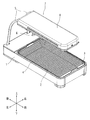
以下本発明を実施の形態に係る加熱調理器を示す図面に基づいて説明する。図1は、加熱調理器を示す外観斜視図、図2は、加熱調理器を示す縦断面図である。以下の説明では、図に示した上下前後左右を使用する。 Hereinafter, the present invention will be described based on the drawings showing a cooking device according to an embodiment. FIG. 1 is an external perspective view showing a heating cooker, and FIG. 2 is a longitudinal sectional view showing the heating cooker. In the following description, the top, bottom, front, back, left and right shown in the figure are used.
加熱調理器は、前後に長い偏平な矩形の筐体1を備える。該筐体1の上面には、その前端部と後部の中途部分との間に開口2が形成されている。該開口2の左右幅は、筐体1の左右幅よりも若干小さい。
The heating cooker includes a flat
開口2の内側には、水を入れるための前後に長い矩形の水トレイ3が形成されている。水トレイ3の前後幅及び左右幅は、開口2の前後幅及び左右幅と略同じである。開口2の上側には、矩形の網4が載置されている。網4は、開口2の縁部分にて支持されている。
Inside the
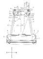
筐体1の後端部から、二つの支持柱5、5が上方に突出している。二つの支持柱5、5は左右方向に並んでいる。二つの支持柱5、5の突出端部には、加熱ユニット7が支持されている。筐体1の上面後端部には、加熱ユニット7の駆動及び停止、並びに後述する第2ヒータ12の出力の変更を行うためのスイッチ6が設けられている。スイッチ6は、軸回りに回転可能な円柱状をなし、軸回りに回転させることによって、第2ヒータ12の出力を無段階で変更することができる。
Two
加熱ユニット7は、網4の上方に配置された前後に長い矩形のケーシング8を備える。ケーシング8の前後幅は網4の前後幅に略等しく、ケーシング8の左右幅は網4の左右幅よりも短い。ケーシング8は網4の左右方向中央部分に対向するように配置されている。ケーシング8の上面は略水平に延びている。
The
ケーシング8の下面は開口しており、ケーシング8の内側には第1ヒータ11及び第2ヒータ12が収納されている。第1ヒータ11は前後に延びた円柱状をなし、ケーシング8の左側に配置されている。第2ヒータ12は前後に延びた円柱状をなし、ケーシング8の右側に配置されている。
The lower surface of the
第1ヒータ11及び第2ヒータ12は、赤外線等を放射して、熱を放射するカーボンヒータであり、交流電源によって電力が供給される。加熱ユニット7の駆動又は停止によって、第1ヒータ11はオン又はオフする。第1ヒータ11の出力は予め所定値に定められており、加熱ユニット7の駆動後、すなわち第1ヒータ11をオンにした後は変更することはできない。なお所定値とは、一定値に限定されず、一定値を基準にした所定の変動幅をも含む。
The
第2ヒータ12は、その出力を変更することができる。スイッチ6を操作することによって、第2ヒータ12に供給される交流電源の出力波形に係る位相が制御され、第2ヒータ12の出力が変更される。ケーシング8には、位相制御を行う制御回路(図示略)が設けられている。制御回路には、ノイズフィルタが実装されており、位相制御の実行によって発生するノイズは、ノイズフィルタによって除去される。ノイズの除去によって、ノイズは、電気用品安全法等の法律によって定められた範囲内に抑制される。
The
ケーシング8には、熱を反射する反射板20が設けられている。反射板20は第1ヒータ11及び第2ヒータ12を上側から覆う。反射板20は、第1ヒータ11を上側から覆う凹状の第1反射部21と、第2ヒータ12を上側から覆う凹状の第2反射部22とを備える。
The
第1反射部21は、下側に第1開口21dを有しており、前後方向に延びた半円筒状をなす。図2に示すように、第1反射部21は上側に突出した曲面21cを備え、該曲面21cの正面断面形状は放物線状をなす。曲面21cの左右縁部には、ケーシング8の上面に対して略垂直な第1対向面21a、21bがそれぞれ形成されている。二つの第1対向面21a、21bは左右方向に対向しており、第1開口21dの左右縁部を形成している。
The first reflecting
二つの第1対向面21a、21bの左右の対向間距離は、上下方向全体に亘って略同じであり、二つの第1対向面21a、21bは互いに平行である。なお二つの第1対向面21a、21bは、正面断面形状が「ハ」の字状になるように形成されてもよい。この場合、二つの第1対向面21a、21bの左右の対向間距離は、下側の対向間距離が上側の対向間距離よりも大きくなる。
The distance between the left and right opposing surfaces of the two first opposing
第2反射部22は、下側に第2開口22fを有しており、前後方向に延びた半角筒状をなす。図2に示すように、第2反射部22の正面断面形状は変形した六角形状をなす。第2反射部22の左右縁部には、互いに対向する二つの第2対向面22a、22bがそれぞれ形成されている。第2反射部22は、二つの第2対向面22a、22bの間に、左面22c、右上面22d及び右面22eを備える。なお左側及び右側の第2対向面22a、22bは、第2開口22fの左縁部及び右縁部をそれぞれ形成する。
The second reflecting
左面22cは、左側の第2対向面22aの上端から右上方向に延びており、左側の第2対向面22aに対して傾斜している。左面22cは、第2ヒータ12からの赤外線等が略真下に反射されるように、傾斜している。右上面22dは、左面22cの右端から右下方向に延びており、第2ヒータ12からの赤外線等が網4の左右方向中央付近に向けて反射されるように、傾斜している。
The
右面22eは、右上面22dの右端と右側の第2対向面22bの上端との間に設けられており、右上面22dの右端から右下方向に延び、第2ヒータ12からの赤外線等が網4の左右方向中央付近に向けて反射されるように、傾斜している。左面22c及び右上面22dによって形成される内角と、右上面22d及び右面22eによって形成される内角とは、いずれも鈍角であり、右上面22d及び右面22eによって形成される内角は、左面22c及び右上面22dによって形成される内角よりも大きい。左面22cは網4の右端側に向いている。一方、右上面22d及び右面22eはいずれも、網4の左右方向中央付近を向いている。
The
左側の第2対向面22aは、ケーシング8の上面に対して略垂直である。一方、右側の第2対向面22bは、ケーシング8の上面に対して傾斜している。二つの第2対向面22a、22bの左右の対向間距離は、下側の対向間距離が上側の対向間距離未満である。左側の第2対向面22aと右側の第2対向面22bの下端部との間の距離d2は、左側の第2対向面22aと右側の第2対向面22bの上端部との間の距離d3よりも短い。すなわち、右側の第2対向面22bの下端部は、上端部よりも左側に位置し、第2開口22fは網4の左右中央に向けて窄まるように形成されている。
The left second facing
図2に示すように、左右の第1対向面21a、21bそれぞれから、下方に延ばした二つの延長線L1、L2は、交差することなく、網4に至る。一方、左右の第2対向面22a、22bそれぞれから、下方に延ばした二つの延長線L3、L4は、網4の左右方向中央付近のやや上方で交差する。
As shown in FIG. 2, two extension lines L1 and L2 extending downward from the left and right first opposing
第1反射部21の左右幅d1は第2反射部22の左右幅d2、d3よりも大きい。第1反射部21及び第2反射部22の前後方向の長さは略同じであり、第1開口21dの開口面積は、第2開口22fの開口面積よりも大きい。
The left and right width d1 of the first reflecting
上述したように、第2開口22fは網4の中央に向けて、左右中央に向けて窄まるように形成されている。また第2反射部22の左面22cは、第2ヒータ12からの赤外線等が略真下に反射されるように傾斜しており、右上面22dは、第2ヒータ12からの赤外線等が網4の左右方向中央付近に向けて反射されるように傾斜しており、右面22eは、第2ヒータ12からの赤外線等が網4の左右方向中央付近に向けて反射されるように傾斜している。そのため、第2ヒータ12の熱の照射範囲は、網4の中央付近に集中する。
As described above, the
図2に示すように、第1ヒータ11の軸心は、断面放物線状をなす曲面21cの頂点の接線(準線)L5に垂直な垂線Hよりも、やや右側に偏倚した位置に配置されている。換言すれば、第1ヒータ11の軸心は、網4の左右方向中央側に偏倚した位置に配置されている。垂線H上に焦点が位置するので、第1ヒータ11は焦点よりも網4の中央側に偏倚した位置に配置される。そのため、第1反射部21(曲面21c)からの赤外線等による放射熱は、直下ではなく、網4の中央付近から右側に亘って拡散するように、斜めに照射される。また第1ヒータ11は第2ヒータ12よりも上側に位置しており、第2ヒータ12に比べて、網4に対する熱の照射範囲がより大きくなり、より広角に熱を照射する。
As shown in FIG. 2, the axis of the
ユーザは網4に食品を載置して、スイッチ6を操作し、第1ヒータ11及び第2ヒータ12をオンにする。上述したように、第1ヒータ11の熱の照射範囲は第2ヒータ12に比べて広く、第1ヒータ11は広角に熱を照射して、食品に平均的に熱を供給する。第2ヒータ12は、食品に対して集中的に熱を供給し、特に、網4の中央付近に位置する部位に集中的に熱を供給する。そのため、例えば、魚などの中央付近が分厚い食品は、分厚い部分に熱が集中して供給され、分厚い部分と分厚い部分から離れた部分との間で、焼具合に差が出ることを抑制することができる。
The user places food on the net 4 and operates the
更に、スイッチ6を無段階で操作することによって、食品の特性、例えば、火の通り易さ、最善の食味を引き出す温度等に応じて、第2ヒータ12の出力を変更し、微調整することができる。
Further, by operating the
実施の形態に係る加熱調理器にあっては、第1ヒータ11の出力を変更不能にし、第2ヒータ12の出力を可変とする。第2ヒータ12のみの出力を変更するため、ノイズの発生そのものが抑制され、したがって、安価なノイズフィルタでも、電気用品安全法等の法律によって定められた範囲内にノイズを抑制することができる。
In the heating cooker according to the embodiment, the output of the
また第1反射部21の第1開口21dを広角に開けて、予め定めた所定値の出力によって、食品の調理面全体を加熱する。一方、第2反射部22の第2開口22fを狭めて、食品の特定部位に出力可変の第2ヒータ12の熱を集中させることによって、調理温度を上げ且つ調理温度を微調整することができる。
Further, the
また第1開口21dの開口面積を第2開口22fの開口面積よりも大きくして、第1ヒータ11からの熱を発散させやすくし、第2ヒータ12からの熱を食品に集中させやすくする。
Further, the opening area of the
また第1反射部21の断面形状を放物線状にして、第1ヒータ11を第1反射部21の頂点よりも網4の中央側に配置することで、第1ヒータ11からの熱が真下ではなく、網4の中央側に拡散して放射され、食品に平均的に供給される。また第2反射部22の断面形状を多角形状にすることで、第2ヒータ12からの熱は食品に集中しやすくなる。
Moreover, the cross-sectional shape of the
なお第1開口21dの前後縁部それぞれに第1対向面21a、21bと同様な対向面を設けてもよい。また第2開口21dの前後縁部それぞれに第2対向面22a、22bと同様な対向面を設けてもよい。
In addition, you may provide the opposing surface similar to the 1st opposing
今回開示した実施の形態は、全ての点で例示であって、制限的なものではないと考えられるべきである。各実施例にて記載されている技術的特徴は互いに組み合わせることができ、本発明の範囲は、特許請求の範囲内での全ての変更及び特許請求の範囲と均等の範囲が含まれることが意図される。 It should be thought that embodiment disclosed this time is an illustration and restrictive at no points. The technical features described in each embodiment can be combined with each other, and the scope of the present invention is intended to include all modifications within the scope of claims and the scope equivalent to the scope of claims. Is done.
4 網
11 第1ヒータ
12 第2ヒータ
20 反射板
21 第1反射部
22 第2反射部
4 Net 11
Claims (4)
前記複数の電気ヒータは、
出力を変更不能な第1ヒータと、
交流電源の出力波形に係る位相を制御することによって、出力を変更可能な第2ヒータと
を備えることを特徴とする加熱調理器。 In a cooking device comprising a net and a plurality of electric heaters disposed above the net and using an AC power source,
The plurality of electric heaters are:
A first heater whose output cannot be changed;
A heating cooker comprising: a second heater capable of changing an output by controlling a phase related to an output waveform of an AC power supply.
下側に第2開口を有し、前記第2ヒータを上側から覆う凹状の第2反射部と
を備え、
前記第1反射部は、前記第1開口の少なくとも一部を形成し、互いに対向する複数の第1対向面を有し、
前記複数の第1対向面の対向間距離は、下側の対向間距離が上側の対向間距離以上であり、
前記第2反射部は、前記第2開口の少なくとも一部を形成し、互いに対向する複数の第2対向面を有し、
前記複数の第2対向面の対向間距離は、下側の対向間距離が上側の対向間距離未満であること
を特徴とする請求項1に記載の加熱調理器。 A concave first reflecting portion having a first opening on the lower side and covering the first heater from above;
A concave second reflecting portion having a second opening on the lower side and covering the second heater from the upper side,
The first reflecting portion has at least a part of the first opening and has a plurality of first facing surfaces facing each other.
The facing distance between the plurality of first facing surfaces is such that the lower facing distance is greater than or equal to the upper facing distance.
The second reflecting portion forms at least a part of the second opening and has a plurality of second facing surfaces facing each other,
2. The cooking device according to claim 1, wherein the distance between the facing surfaces of the plurality of second facing surfaces is such that the lower facing distance is less than the upper facing distance.
を特徴とする請求項2に記載の加熱調理器。 The cooking device according to claim 2, wherein an opening area of the first opening is larger than an opening area of the second opening.
前記第1ヒータは、前記第1反射部の頂点よりも前記網の中央側に偏倚した位置に配置されており、
前記第2反射部の断面形状は多角形状をなすこと
を特徴とする請求項2又は3に記載の加熱調理器。 The cross-sectional shape of the first reflecting portion is a parabolic shape,
The first heater is arranged at a position biased toward the center side of the net from the apex of the first reflecting portion,
The cooking device according to claim 2 or 3, wherein a cross-sectional shape of the second reflecting portion is a polygonal shape.
Priority Applications (1)
| Application Number | Priority Date | Filing Date | Title |
|---|---|---|---|
| JP2016079866A JP6633442B2 (en) | 2016-04-12 | 2016-04-12 | Cooker |
Applications Claiming Priority (1)
| Application Number | Priority Date | Filing Date | Title |
|---|---|---|---|
| JP2016079866A JP6633442B2 (en) | 2016-04-12 | 2016-04-12 | Cooker |
Publications (2)
| Publication Number | Publication Date |
|---|---|
| JP2017190898A true JP2017190898A (en) | 2017-10-19 |
| JP6633442B2 JP6633442B2 (en) | 2020-01-22 |
Family
ID=60085870
Family Applications (1)
| Application Number | Title | Priority Date | Filing Date |
|---|---|---|---|
| JP2016079866A Active JP6633442B2 (en) | 2016-04-12 | 2016-04-12 | Cooker |
Country Status (1)
| Country | Link |
|---|---|
| JP (1) | JP6633442B2 (en) |
Cited By (1)
| Publication number | Priority date | Publication date | Assignee | Title |
|---|---|---|---|---|
| EP3921578B1 (en) * | 2019-02-06 | 2024-04-03 | Mélédo, Hervé | Even cooking of foodstuffs by means of a device allowing static isolation, focusing, channeling and modulation of energies |
Citations (6)
| Publication number | Priority date | Publication date | Assignee | Title |
|---|---|---|---|---|
| JPS57200117A (en) * | 1981-06-02 | 1982-12-08 | Matsushita Seiko Kk | Cooker |
| JPH0492616A (en) * | 1990-08-07 | 1992-03-25 | Mitsubishi Electric Home Appliance Co Ltd | Oven toaster |
| JPH06281166A (en) * | 1993-03-30 | 1994-10-07 | Sanyo Electric Co Ltd | Heating device |
| JPH0783448A (en) * | 1993-09-13 | 1995-03-28 | Matsushita Electric Ind Co Ltd | Heating cooker |
| JP2003279054A (en) * | 2002-03-20 | 2003-10-02 | Matsushita Electric Ind Co Ltd | Cooking device |
| US20120192851A1 (en) * | 2008-07-11 | 2012-08-02 | Breville Pty Limited | Oven with Interface Device |
-
2016
- 2016-04-12 JP JP2016079866A patent/JP6633442B2/en active Active
Patent Citations (6)
| Publication number | Priority date | Publication date | Assignee | Title |
|---|---|---|---|---|
| JPS57200117A (en) * | 1981-06-02 | 1982-12-08 | Matsushita Seiko Kk | Cooker |
| JPH0492616A (en) * | 1990-08-07 | 1992-03-25 | Mitsubishi Electric Home Appliance Co Ltd | Oven toaster |
| JPH06281166A (en) * | 1993-03-30 | 1994-10-07 | Sanyo Electric Co Ltd | Heating device |
| JPH0783448A (en) * | 1993-09-13 | 1995-03-28 | Matsushita Electric Ind Co Ltd | Heating cooker |
| JP2003279054A (en) * | 2002-03-20 | 2003-10-02 | Matsushita Electric Ind Co Ltd | Cooking device |
| US20120192851A1 (en) * | 2008-07-11 | 2012-08-02 | Breville Pty Limited | Oven with Interface Device |
Cited By (2)
| Publication number | Priority date | Publication date | Assignee | Title |
|---|---|---|---|---|
| EP3921578B1 (en) * | 2019-02-06 | 2024-04-03 | Mélédo, Hervé | Even cooking of foodstuffs by means of a device allowing static isolation, focusing, channeling and modulation of energies |
| US12245723B2 (en) | 2019-02-06 | 2025-03-11 | Hervé MÉLÉDO | Even cooking of foodstuffs by means of a device allowing static isolation, focusing, channeling and modulation of energies |
Also Published As
| Publication number | Publication date |
|---|---|
| JP6633442B2 (en) | 2020-01-22 |
Similar Documents
| Publication | Publication Date | Title |
|---|---|---|
| JP6528153B2 (en) | Heat source multiple irradiation type infrared cooker | |
| KR100760821B1 (en) | Oven | |
| KR101539900B1 (en) | Improvement cooking pan with both sides heating part | |
| JP2015052446A (en) | Heater unit and heating cooker equipped with the heater unit | |
| RU2282791C2 (en) | Heating device for microwave stove and method of heating food products | |
| KR20140002962U (en) | Improvement cooking pan with both sides heating part having height adjustment means | |
| CA2766529A1 (en) | Electric oven with a heating element reflector | |
| JP6633442B2 (en) | Cooker | |
| JP5169494B2 (en) | Toaster oven | |
| KR101615893B1 (en) | infrared ray cooker having paraboloidal reflector | |
| KR102595700B1 (en) | Double grill with direct fire control structure | |
| KR101651209B1 (en) | Electric range having double heater | |
| KR101474767B1 (en) | Cooking apparatus | |
| JP6690145B2 (en) | Heating cooker | |
| JP2009277559A (en) | Heating cooker | |
| JP6149002B2 (en) | Electric cooker | |
| KR101694156B1 (en) | A multifunctional roaster | |
| JP2000205573A (en) | Even Star | |
| JP2001074249A (en) | Toaster oven | |
| JPH02186582A (en) | Toaster oven | |
| JP2013111468A (en) | Heating cooking device | |
| CN211484137U (en) | Baking tray assembly and baking machine | |
| KR200463874Y1 (en) | Skewered roaster | |
| JP6840580B2 (en) | Heating device | |
| JPS60240923A (en) | Electric cooker |
Legal Events
| Date | Code | Title | Description |
|---|---|---|---|
| A621 | Written request for application examination |
Free format text: JAPANESE INTERMEDIATE CODE: A621 Effective date: 20190123 |
|
| TRDD | Decision of grant or rejection written | ||
| A977 | Report on retrieval |
Free format text: JAPANESE INTERMEDIATE CODE: A971007 Effective date: 20191127 |
|
| A01 | Written decision to grant a patent or to grant a registration (utility model) |
Free format text: JAPANESE INTERMEDIATE CODE: A01 Effective date: 20191203 |
|
| A61 | First payment of annual fees (during grant procedure) |
Free format text: JAPANESE INTERMEDIATE CODE: A61 Effective date: 20191212 |
|
| R150 | Certificate of patent or registration of utility model |
Ref document number: 6633442 Country of ref document: JP Free format text: JAPANESE INTERMEDIATE CODE: R150 |
|
| R250 | Receipt of annual fees |
Free format text: JAPANESE INTERMEDIATE CODE: R250 |
|
| R250 | Receipt of annual fees |
Free format text: JAPANESE INTERMEDIATE CODE: R250 |