JP2013111468A - Heating cooking device - Google Patents
Heating cooking device Download PDFInfo
- Publication number
- JP2013111468A JP2013111468A JP2011276428A JP2011276428A JP2013111468A JP 2013111468 A JP2013111468 A JP 2013111468A JP 2011276428 A JP2011276428 A JP 2011276428A JP 2011276428 A JP2011276428 A JP 2011276428A JP 2013111468 A JP2013111468 A JP 2013111468A
- Authority
- JP
- Japan
- Prior art keywords
- heaters
- heated
- far
- heater
- heating
- Prior art date
- Legal status (The legal status is an assumption and is not a legal conclusion. Google has not performed a legal analysis and makes no representation as to the accuracy of the status listed.)
- Pending
Links
Images

Abstract
Description
本発明は、遠赤外線を周囲から効率的に照射して被加熱物である鶏肉や魚や野菜等の食品を加熱調理する装置の改良に関する。The present invention relates to an improvement in an apparatus for heating and cooking food such as chicken, fish, and vegetables by efficiently irradiating far infrared rays from the surroundings.
遠赤外線の加熱利用は昭和40年代から盛んになり、主として自動車産業に関する塗装乾燥から始まり、加熱処理が短時間で行われることから生産性向上や加熱炉長が短くなることによる省スペ−スの技術として工業界では広く使用され始めた。現在では、熱処理工程の一部門として広く採用されるようになった。Far-infrared heating has become popular since the Showa 40's, mainly starting with paint drying related to the automobile industry, and since heat treatment is performed in a short time, the productivity is reduced and the length of the heating furnace is shortened. The technology began to be widely used in the industry. At present, it has been widely adopted as a division of the heat treatment process.
一方、食材の加熱方法としても、ガスバ−ナ−の高温燃焼ガスで直接、食材を焼くと表面だけが炭化し易くなり、また、燃焼ガスで鍋等を加熱して、その高温表面に食材を接触させて加熱すると、食材の内部にまで熱が伝わるまでに時間が掛かってしまう欠点がある。そこで、遠赤外線を利用すると電磁波の形で直接、食材に吸収され、その表面も内部も短時間で加熱される特徴がある。具体的には鰻のカバ焼きや焼き鳥の加熱方法である。On the other hand, as a method of heating food, if the food is baked directly with the high-temperature combustion gas of the gas burner, only the surface is easily carbonized, and the pan is heated with the combustion gas, and the food is applied to the high-temperature surface. When heated by contact, there is a drawback that it takes time until the heat is transmitted to the inside of the food. Therefore, when far infrared rays are used, they are directly absorbed by food materials in the form of electromagnetic waves, and the surface and the inside are heated in a short time. Specifically, it is a method for heating a grilled salmon or grilled chicken.
しかしながら、調理用加熱装置としては、従来より、特許文献1にみられるように、輻射熱で食品に焦げ目をつけるグリル機能と雰囲気温度と遠赤外線で食品温度を上昇させるオ−ブン機能を併せ持つオ−ブン電子レンジとして二種類のヒ−タ−を天井部分に設け、更に下部にも加熱用のヒ−タ−が設けられたオ−ブンが提案されている。これだけ数種類のヒ−タ−を設けても、被加熱物は下部に静置されており、その大きさが変われば、各ヒ−タ−からの熱の利用効率が最適にはならず、しかもドリップが発生すると下部ヒ−タ−上に落ちる欠点がある。However, as seen in
また、特許文献2にみられるように、燃焼ガスを左右の壁および天井に流して耐熱金属板製の壁面から放射される輻射熱で被加熱物を加熱する方法が提案されている。しかし、被加熱物は下のトレ−の上に設けられた網にのせて加熱されるので、被加熱物の上面と下面で加熱状態に差が発生してしまう欠点がある。Further, as seen in Patent Document 2, there has been proposed a method of heating an object to be heated with radiant heat radiated from a wall surface made of a heat-resistant metal plate by flowing a combustion gas to the left and right walls and the ceiling. However, since the object to be heated is heated on a net provided on the lower tray, there is a drawback that a difference in heating state occurs between the upper surface and the lower surface of the object to be heated.
そこで、本発明者は、株式会社ドライアップジャパンのインタ−ネットホ−ムページおよび非特許文献1にみられるような、被加熱物を回転自在に吊り下げ、その周囲に複数の遠赤外線ヒ−タ−を設け、その外側に該ヒ−タ−の輻射熱を反射させる金属板を設けた竪型加熱調理装置を開発した。代表的な使用方法として焼芋を製造する装置として販売している。しかし、例えば、ほぼ同じ大きさの芋を専用に焼く装置としてならば問題無いが、被加熱体の大きさが小さくなるとヒータ−と被加熱体との間の距離が長くなり、その間に存在する蒸発した水分からなる極性を有する水蒸気に遠赤外線が吸収され、その結果、加熱に要する時間が長くなる欠点がある。Therefore, the present inventor suspends an object to be heated as shown in the Internet home page of Dryup Japan Co., Ltd. and Non-Patent
一般家庭や居酒屋等の小規模飲食店では、1台でいろいろな種類および大きさの食材を効率よく加熱することが望まれている。従って、本発明の主な目的は、ブロイラ−、魚、ナス、ゴ−ヤ、トウモロコシ、サツマイモ等のいろいろな種類および大きさの食材を効率よく加熱することができる加熱調理装置を提供することにある。In small-scale restaurants such as general households and taverns, it is desired to efficiently heat various kinds and sizes of food with a single unit. Accordingly, a main object of the present invention is to provide a cooking device capable of efficiently heating various kinds and sizes of ingredients such as broiler, fish, eggplant, goya, corn, and sweet potato. is there.
本発明者は、従来技術の問題点に鑑みて鋭意研究を重ねた結果、ヒータ−の位置および吊り下げ部の位置を調整することにより上記目的を達成できることを見出し、本発明を完成するに至った。As a result of intensive studies in view of the problems of the prior art, the present inventor has found that the above object can be achieved by adjusting the position of the heater and the position of the hanging portion, and has completed the present invention. It was.
すなわち、本発明は、被加熱物を回転自在に吊り下げ、その周囲に複数の遠赤外線ヒ−タ−を設け、その外側に該ヒ−タ−の輻射熱を反射させる金属板を設けた竪型加熱調理装置において、複数の遠赤外線ヒ−タ−がその外側の可撓性を有する金属製の反射板と一緒に移動自在な構造を特徴とする加熱調理装置を提供するものである。That is, the present invention suspends an object to be heated in a rotatable manner, provides a plurality of far-infrared heaters around it, and a metal plate provided with a metal plate that reflects the radiant heat of the heater on the outside thereof. In the cooking apparatus, a cooking apparatus characterized by a structure in which a plurality of far infrared heaters are movable together with a flexible metal reflector on the outside thereof is provided.
さらに、各ヒ−タ−からの被加熱物との距離を調整できるように、被加熱物の吊り下げ位置が移動自在な構造を特徴とする加熱調理装置を提供するものである。Furthermore, the present invention provides a cooking device characterized by a structure in which the suspended position of the object to be heated is movable so that the distance from each heater to the object to be heated can be adjusted.
本発明によれば、一般家庭や居酒屋等の小規模飲食店で、1台で色々な食材の大きさに応じて、遠赤外線ヒ−タ−の位置とその食材の吊り下げ位置を調整することにより、最も加熱効率が良く、短時間で加熱できる調理装置を提供することができる。ADVANTAGE OF THE INVENTION According to this invention, the position of a far-infrared heater and the hanging position of the foodstuff are adjusted according to the magnitude | size of various foodstuffs with one unit at small restaurants, such as a general household and a pub. Thus, it is possible to provide a cooking apparatus that has the highest heating efficiency and can be heated in a short time.
さらに、本発明の加熱方式によれば、被加熱物を非接触の状態で加熱するので、従来の石焼き芋のように表面が焦げて、そこから水分が蒸発してしまうことも無く、内部の水分が残った状態で焼ける。その結果、ジュ−シ−な料理を提供することが可能となる。Furthermore, according to the heating method of the present invention, the object to be heated is heated in a non-contact state, so that the surface is not burnt like conventional stone-baked potatoes, and moisture does not evaporate from the inside. Bake with moisture left. As a result, it becomes possible to provide a succulent dish.
また、例えば魚のように加熱中にドリップが発生しても、装置の底には油受けを設けるか、または外部に抜くことができるので、ドリップが燃えて煙が出るようなことは無く被加熱物が煙臭くならないし、また装置が汚れ難い。In addition, even if a drip occurs during heating, such as a fish, an oil pan can be provided at the bottom of the device, or it can be pulled out to the outside so that the drip does not burn and smoke does not come out. Things do not smoke and the device is difficult to get dirty.
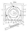
次に、図面を参照して第一の発明の実施の形態を説明する。図1は、本発明に係る加熱調理装置の一例の平面断面の概略図である。本体1は周囲の壁の中に断熱材2を設け、天井3には図示されていないが内部で発生した蒸気を逃がす複数の孔が設けられている。Next, an embodiment of the first invention will be described with reference to the drawings. FIG. 1 is a schematic cross-sectional view of an example of a cooking device according to the present invention. The
図2は図1のA−A矢視の補助線で切断された概略側面図である。吊り具4は天井3の上に設置されたスライド可能な吊り具用駆動装置5により自転し、その吊り具に被加熱物6が吊り下げられながら自転する。FIG. 2 is a schematic side view cut along an auxiliary line as viewed in the direction of arrows AA in FIG. The hanger 4 is rotated by a slidable hanger drive device 5 installed on the
その被加熱物の周囲には、金属製の輻射熱反射板7が設けられ、その内側には遠赤外線ヒ−タ−9及び9’が複数本設けられ、ヒータ−9は固定されているが、ヒータ−9’は反射板7と一緒に移動できる。A metal radiant
該反射板7は薄い金属製で、その内側面には複数の折り目8が加工され、可撓性がある。該反射板7の端は本体の前面側に設けられたストッパ−10に差し込まれており、容易に抜き差しできる。被加熱物を吊り具に吊るす場合は、反射板の端をP1の位置に差し込み、吊るし終わったら反射板の端を抜いて、P2及びP3のような、被加熱物が遠赤外線ヒ−タ−9’により効率的な加熱ができる位置に差し込む。The reflecting
本体の前面には扉11が設けられ、内部の様子が観察できるように透明な耐熱ガラス12が組み込まれている。運転中は、扉11が閉じられた状態で被加熱体6が自転しながら複数の遠赤外線ヒータ−9及び9’により加熱され、内部で発生した蒸気は天井3に開けられた孔から抜け、ドリップが発生すればドリップ排出孔13から外部に取り出される。A door 11 is provided on the front surface of the main body, and a transparent heat-resistant glass 12 is incorporated so that the inside can be observed. During operation, while the door 11 is closed, the heated body 6 is heated by the plurality of far infrared heaters 9 and 9 ′ while rotating, and the steam generated inside escapes from the hole formed in the
遠赤外線ヒ−タ−は3本に限定されるものではなく、4本以上設けられても良い。The far infrared heaters are not limited to three, and four or more far infrared heaters may be provided.
次に、第二の発明の実施の形態を説明する。被加熱物の大きさに従ってそれを吊るす吊り具の位置を調整する。すなわち被加熱物6が大きな場合は、反射板7の端はストッパ−のP2の位置に差し込まれ、被加熱物が6’が小さな場合は、反射板7の端はストッパ−のP3の位置に差し込まれ、さらに該被加熱物6及び6’とヒ−タ−9及び9’の距離が概略等しくなるように吊り具4および4’は距離Lだけ吊り具用駆動装置5および5’と一緒にスライドし固定する。このように調整することにより、色々な大きさの被加熱物を効率よく加熱することが可能となる。Next, an embodiment of the second invention will be described. Adjust the position of the hanger that hangs it according to the size of the object to be heated. That is, when the object to be heated 6 is large, the end of the reflecting
以下に実施例を示し、本発明の特徴をより具体的に説明する。ただし、本発明の範囲は、実施例に限定されない。 The features of the present invention will be described more specifically with reference to examples. However, the scope of the present invention is not limited to the examples.
内のり寸法が、幅350mm、奥行き300mm、高さ460mmの大きさの加熱調理装置本体1に、100V500Wの遠赤外線ヒ−タ−9及び9’を3本設け、その内の1本のヒータ−9は固定し、残りの2本のヒ−タ−9’を複数の折り目を表面に加工したステンレス薄板製の輻射熱反射板7の内側に取り付けて、被加熱物6として吊り具4に吊り下げられたブロイラ−と、各3本のヒータ−9及び9’との間の距離が、概略等しくなるように反射板7の端をストッパ−10のP2位置に差し込み、扉11を閉めて、ヒータ−出力80%で加熱した結果、50分間で焼きあがった。なお、該ブロイラ−の最大直径は約210mmあった。The
実施例1の装置を使って、ブロイラ−の代わりに、そのまま最大直径約60mmのサツマイモを加熱した結果、大きさがかなり小さいにも拘わらず、焼きあがるのに、同じく50分間も掛かった。そこで、サツマイモと、各3本のヒータ−9及び9’との間の距離が、概略等しくなるように反射板7の端をストッパ−10のP3位置に差し込み、吊り具4’を吊り具用駆動装置5’と一緒に吊り下げ位置を約35mmスライドして固定した後、扉11を閉めて、ヒータ−出力80%で加熱した結果、30分間で焼きあがった。As a result of heating the sweet potato having a maximum diameter of about 60 mm as it was instead of the broiler using the apparatus of Example 1, it took 50 minutes to bake although it was quite small. Therefore, the end of the
本発明は、一般家庭や居酒屋等の小規模飲食店にて1台でいろいろな種類および大きさの食材、例えばブロイヤ−、魚、ナス、ゴ−ヤ、トウモロコシ、サツマイモ等を効率よく加熱することができる加熱調理装置に関するものである。The present invention efficiently heats various kinds and sizes of foods such as broiler, fish, eggplant, goya, corn, sweet potato, etc. in a single small-scale restaurant such as a general household or a tavern. It is related with the heat cooking apparatus which can do.
1 本体
4、4’ 吊り具
5、5’ 吊り具用駆動装置
6、6’ 被加熱物
7 輻射熱反射板
8 折り目
9、9’ 遠赤外線ヒ−タ−
10 反射板端ストッパ−
11 扉DESCRIPTION OF
10 Reflector end stopper
11 Door
Claims (2)
Priority Applications (1)
| Application Number | Priority Date | Filing Date | Title |
|---|---|---|---|
| JP2011276428A JP2013111468A (en) | 2011-11-30 | 2011-11-30 | Heating cooking device |
Applications Claiming Priority (1)
| Application Number | Priority Date | Filing Date | Title |
|---|---|---|---|
| JP2011276428A JP2013111468A (en) | 2011-11-30 | 2011-11-30 | Heating cooking device |
Publications (1)
| Publication Number | Publication Date |
|---|---|
| JP2013111468A true JP2013111468A (en) | 2013-06-10 |
Family
ID=48707609
Family Applications (1)
| Application Number | Title | Priority Date | Filing Date |
|---|---|---|---|
| JP2011276428A Pending JP2013111468A (en) | 2011-11-30 | 2011-11-30 | Heating cooking device |
Country Status (1)
| Country | Link |
|---|---|
| JP (1) | JP2013111468A (en) |
Cited By (2)
| Publication number | Priority date | Publication date | Assignee | Title |
|---|---|---|---|---|
| CN107334387A (en) * | 2017-04-14 | 2017-11-10 | 宁波方太厨具有限公司 | One kind baking cooking equipment |
| CN115299551A (en) * | 2022-07-29 | 2022-11-08 | 长乐聚泉食品有限公司 | Steaming device for roasted eel processing and steaming method thereof |
-
2011
- 2011-11-30 JP JP2011276428A patent/JP2013111468A/en active Pending
Cited By (4)
| Publication number | Priority date | Publication date | Assignee | Title |
|---|---|---|---|---|
| CN107334387A (en) * | 2017-04-14 | 2017-11-10 | 宁波方太厨具有限公司 | One kind baking cooking equipment |
| CN107334387B (en) * | 2017-04-14 | 2023-08-18 | 宁波方太厨具有限公司 | Baking cooking equipment |
| CN115299551A (en) * | 2022-07-29 | 2022-11-08 | 长乐聚泉食品有限公司 | Steaming device for roasted eel processing and steaming method thereof |
| CN115299551B (en) * | 2022-07-29 | 2024-01-30 | 长乐聚泉食品有限公司 | Steaming device and steaming method for processing roasted eels |
Similar Documents
| Publication | Publication Date | Title |
|---|---|---|
| JP6689149B2 (en) | Heating cooker and heating method using superheated steam | |
| KR100833966B1 (en) | Cooking pan heated by infrared rays | |
| JP6588591B2 (en) | Cooker | |
| KR101520498B1 (en) | Oven range including a rotational rack | |
| CN1904484A (en) | Heating cooker | |
| JP2015052446A (en) | Heater unit and heating cooker equipped with the heater unit | |
| JP2013111468A (en) | Heating cooking device | |
| KR200371963Y1 (en) | Cooking pan | |
| RU103458U1 (en) | DEVICE FOR COOKING | |
| JP2014234932A (en) | Heating cooker | |
| JP2010172351A (en) | Radiation pot | |
| JP4179252B2 (en) | Built-in induction heating cooker | |
| JP2011102661A (en) | Heating cooker | |
| CN103720344A (en) | Steam heating furnace | |
| JP5732427B2 (en) | Cooker | |
| KR20080006689U (en) | Barbecue grill equipped with halogen ceramic heater | |
| KR102595700B1 (en) | Double grill with direct fire control structure | |
| JP6355403B2 (en) | Pottery cooker | |
| JP5583626B2 (en) | Means to achieve uniformity of thermal power and temperature in the oven cabinet | |
| KR101917522B1 (en) | Movable elvan grille | |
| JP2007187433A (en) | Microwave oven | |
| JP2011196603A (en) | Heating cooker | |
| JP2001182947A (en) | Heating cooking appliance | |
| JP3157593U (en) | Heat repeater for cooking | |
| KR200434499Y1 (en) | Far infrared ray barbecue cooker |