JP2017190828A - Hammer vibration suppression structure of transmission - Google Patents
Hammer vibration suppression structure of transmission Download PDFInfo
- Publication number
- JP2017190828A JP2017190828A JP2016080283A JP2016080283A JP2017190828A JP 2017190828 A JP2017190828 A JP 2017190828A JP 2016080283 A JP2016080283 A JP 2016080283A JP 2016080283 A JP2016080283 A JP 2016080283A JP 2017190828 A JP2017190828 A JP 2017190828A
- Authority
- JP
- Japan
- Prior art keywords
- helical gear
- gear
- transmission
- input shaft
- helical
- Prior art date
- Legal status (The legal status is an assumption and is not a legal conclusion. Google has not performed a legal analysis and makes no representation as to the accuracy of the status listed.)
- Pending
Links
Images


Landscapes
- Gear Transmission (AREA)
Abstract
【課題】回転方向の歯打ち振動の発生を抑制する。【解決手段】本発明に係る変速機の歯打ち振動抑制構造は、第1のはすば歯車20aが設けられた入力軸12と、第1のはすば歯車20aが噛み合う第2のはすば歯車20bが設けられ、入力軸12と並列に配置されたカウンタ軸16と、を回転可能に収容する変速機ケース18を備える変速機において、入力軸12をその軸方向の所定位置に回転自在に保持する保持手段と、第1のはすば歯車20a及び第2のはすば歯車20bの対20における「はすば」のねじれ方向に依存してカウンタ軸16に及ぼされるスラスト力を相殺する軸方向に、カウンタ軸16を回転自在に付勢する付勢手段が設けられている。【選択図】図1Generation of rattling vibration in the rotational direction is suppressed. A gear rattle vibration suppressing structure according to the present invention includes a second helical gear in which an input shaft provided with a first helical gear and a first helical gear are engaged. In a transmission having a transmission case 18 provided with a gear 20b and rotatably accommodating a counter shaft 16 arranged in parallel with the input shaft 12, the input shaft 12 is freely rotatable to a predetermined position in the axial direction thereof. And the thrust force exerted on the counter shaft 16 depending on the twist direction of the "helical" in the pair 20 of the first helical gear 20a and the second helical gear 20b. An urging means for urging the counter shaft 16 rotatably is provided in the axial direction. [Selection] Figure 1
Description
本発明は、変速機の歯打ち振動抑制構造、特に、はすば歯車対を備える変速機の歯打ち振動抑制構造に関する。 The present invention relates to a structure for suppressing rattling vibration of a transmission, and more particularly to a structure for suppressing rattling vibration of a transmission including a helical gear pair.
一般に、駆動力源であるエンジンにクラッチ等を介して連結される入力軸と、それと同軸にニードルベアリングなどを介してその軸心まわりに相対回転可能に連結されると共に、差動歯車装置等を介して駆動輪に連結される出力軸と、それら入力軸及び出力軸と並列に設けられたカウンタ軸とを変速機ケース内に備える車両用変速機であって、入力軸に設けられたはすば歯車とカウンタ軸に設けられたはすば歯車との対が噛み合わされて構成されている車両用変速機が知られている(例えば、特許文献1参照)。 In general, an input shaft connected to an engine as a driving force source via a clutch or the like, and a shaft coaxially connected to the input shaft via a needle bearing or the like so as to be relatively rotatable about the shaft center, and a differential gear device or the like. And a countershaft provided in parallel with the input shaft and the output shaft in a transmission case, the transmission being provided on the input shaft. A vehicular transmission is known in which a pair of a helical gear and a helical gear provided on a counter shaft are engaged with each other (see, for example, Patent Document 1).
ところで、上記のはすば歯車の対を備える車両用変速機において、車両の停車中であって、その変速機のシフトポジションがニュートラル、スロットルバルブが全閉、且つクラッチが接続状態にあるときは、エンジンからの駆動力がクラッチ、入力軸に設けられたはすば歯車、及びカウンタ軸に設けられたはすば歯車を介してカウンタ軸に伝達される。この状態では、潤滑油などによりカウンタ軸に及ぼされる回転抵抗はさほど大きくなく、入力軸及びそれに設けられたはすば歯車の回転方向と、それに噛み合っているはすば歯車の対における「はすば」のねじれ方向に依存して、入力軸及びカウンタ軸にそれぞれ逆方向にスラスト力が作用する。この結果、このはすば歯車の対において、それぞれの回転方向の歯面ズレ(又はガタ)及びスラスト方向の歯面ズレ(又はガタ)が発生する。 By the way, in the vehicle transmission having the above-described pair of helical gears, when the vehicle is stopped, the shift position of the transmission is neutral, the throttle valve is fully closed, and the clutch is in a connected state. The driving force from the engine is transmitted to the counter shaft via the clutch, the helical gear provided on the input shaft, and the helical gear provided on the counter shaft. In this state, the rotational resistance exerted on the counter shaft by lubricating oil or the like is not so large, and the rotation direction of the input shaft and the helical gear provided on the input shaft and the pair of helical gears meshed therewith Depending on the torsional direction, a thrust force acts on the input shaft and the counter shaft in opposite directions. As a result, in the helical gear pair, tooth surface deviation (or backlash) in the respective rotation directions and tooth surface deviation (or backlash) in the thrust direction are generated.
かかる状態において、通常アイドリング状態にあるエンジンからのトルク変動が入力軸に負荷されると、入力軸及びそのはすば歯車は変動した回転状態になり、カウンタ軸及びそのはすば歯車は回転方向のズレ又はガタを介して回転とトルクが伝達されるので、回転角振幅差が生じる(図3(A)参照)。その様子は、相対回転角振幅が発生した状態になる(図3(B)参照)。その結果、このような相対回転角振幅が発生した状態では、はすば歯車の対の歯面の衝突が発生し、回転方向の歯打ち振動(音)が発生するという問題が存した。 In this state, when torque fluctuation from an engine that is normally idling is loaded on the input shaft, the input shaft and its helical gear are in a rotating state, and the counter shaft and its helical gear are in the rotational direction. Rotation and torque are transmitted through the deviation or backlash, resulting in a rotation angle amplitude difference (see FIG. 3A). This is the state in which the relative rotation angle amplitude is generated (see FIG. 3B). As a result, in the state in which such a relative rotation angle amplitude is generated, there is a problem that the tooth surfaces of the pair of helical gears collide with each other, and rattling vibration (sound) in the rotation direction is generated.
そこで、本発明はかかる問題を解消すべく創案され、その課題は、このような回転方向の歯打ち振動(音)の発生を抑制することができる変速機の歯打ち振動抑制構造を提供することにある。 Accordingly, the present invention has been devised to solve such a problem, and the problem is to provide a gear rattle vibration suppressing structure that can suppress the occurrence of gear rattle vibration (sound) in the rotational direction. It is in.
上記課題を解決する本発明に係る変速機の歯打ち振動抑制構造は、第1のはすば歯車が設けられた入力軸と、当該第1のはすば歯車が噛み合う第2のはすば歯車が設けられ、前記入力軸と並列に配置されたカウンタ軸と、を回転可能に収容する変速機ケースを備える変速機において、
前記入力軸をその軸方向の所定位置に回転自在に保持する保持手段と、
前記第1のはすば歯車及び第2のはすば歯車の対における「はすば」のねじれ方向に依存して前記カウンタ軸に及ぼされるスラスト力を相殺する軸方向に、前記カウンタ軸を回転自在に付勢する付勢手段が設けられていることを特徴とする。
The gear rattle vibration suppressing structure according to the present invention that solves the above-described problems includes an input shaft provided with a first helical gear and a second helical gear that meshes with the first helical gear. In a transmission provided with a transmission case that is provided with gears and rotatably accommodates a counter shaft arranged in parallel with the input shaft,
Holding means for rotatably holding the input shaft at a predetermined position in the axial direction;
The countershaft is arranged in an axial direction that cancels a thrust force exerted on the countershaft depending on a twist direction of “helical” in the pair of the first helical gear and the second helical gear. An urging means for urging the rotatively is provided.
本発明に係る変速機の歯打ち振動抑制構造によれば、入力軸はその軸方向の所定位置に保持手段によって回転自在に保持され、カウンタ軸は第1のはすば歯車及び第2のはすば歯車の対における「はすば」のねじれ方向に依存してカウンタ軸に及ぼされるスラスト力を相殺する軸方向に、付勢手段によって付勢されているので、前記第1のはすば歯車及び第2のはすば歯車対における「はすば」の歯面間にズレ又はガタの発生が抑制される。これにより、エンジンからのトルク変動が入力軸に負荷される場合であっても、入力軸及びそのはすば歯車とカウンタ軸及びそのはすば歯車とは、回転角振幅差が生じることが抑制される。換言すると、同一の回転角振幅で同期して回転するので、回転方向の歯打ち振動の発生が抑制され、歯打ち音を抑制することができる。 According to the gear rattle vibration suppressing structure of the present invention, the input shaft is rotatably held at a predetermined position in the axial direction by the holding means, and the counter shaft is provided with the first helical gear and the second helical gear. The first helical gear is biased by the biasing means in the axial direction that cancels the thrust force exerted on the counter shaft depending on the twist direction of the “helical” in the pair of helical gears. Generation | occurrence | production of the shift | offset | difference or backlash between the tooth surfaces of the "helical" in a gearwheel and the 2nd helical gear pair is suppressed. As a result, even when torque fluctuation from the engine is applied to the input shaft, the input shaft and its helical gear and the counter shaft and its helical gear are restrained from causing a rotational angle amplitude difference. Is done. In other words, since it rotates in synchronism with the same rotation angle amplitude, generation of rattling vibration in the rotation direction is suppressed, and rattling noise can be suppressed.
次に、添付図面を参照しながら、本発明を実施するための形態について説明する。 Next, embodiments for carrying out the present invention will be described with reference to the accompanying drawings.
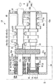
図1は、本発明が好適に適用される車両用手動変速機10の構成を概略的に示す断面図であり、図2(A)は図1における一点鎖線で囲む領域IIの拡大断面図であり、図2(B)は端面図である。
FIG. 1 is a cross-sectional view schematically showing a configuration of a vehicle
車両用の手動変速機10(以下、単に変速機10という)は、FF(フロントエンジン・フロントドライブ)車両に好適に用いられる横置き型の歯車式変速装置であり、図示しないクラッチ等を介して駆動力源である不図示のエンジンに連結される入力軸12と、その入力軸12と同軸に、例えば、ニードルベアリング13を介して軸心まわりに相対回転可能に連結されると共に、図示しない差動歯車装置等を介して駆動輪に連結される出力軸14と、それら入力軸12及び出力軸14と並列に設けられたカウンタ軸16とを、非回転部材である変速機ケース18内に備えて構成されている。さらに、上記変速機10では、入力軸12に設けられた第1のはすば歯車20aとカウンタ軸16に設けられた第2のはすば歯車20bとが相互に噛み合わされて、はすば歯車の対20を構成している。なお、図示しないクラッチの接続時において、上記入力軸12及びカウンタ軸16は駆動力源としてのエンジンからの出力により常に回転される。
A
ここで、本実施形態に係る変速機10においては、図2(A)に示されるように、第1のはすば歯車20aは右ねじりの「はすば」であるのに対し、第2のはすば歯車20bは左ねじりの「はすば」であり、入力軸12の回転方向がエンジンからの負荷の入力方向(図2(A)に矢印Aで示されている)から見て時計回り(図2(B)に矢印Bで示されている)であるとき、入力軸12には矢印C方向のスラスト力が作用するのに対し、カウンタ軸16には矢印D方向のスラスト力が作用する。
Here, in the
上記変速機10は、例えば、運転席近傍に設けられた図示しないシフト操作装置の操作に応じて、複数の変速段のうちのいずれかを選択的に成立させる機械式の手動変速機である。
The
本実施形態に係る変速機10は、変速機ケース18の一部として軸心方向に直交して配置された中間隔壁18aを備えている。そして、入力軸12は中間隔壁18aに取付けられた後述の第1の環状支持部材22を介して支持された第1の玉軸受24aによって回転自在に支持されている。なお、入力軸12に同軸にニードルベアリング13を介してその軸心まわりに相対回転可能に連結された出力軸14は、さらに変速機ケース18の端壁(図1では右端壁)に第2の玉軸受24bによって回転自在に支持されている。第1の環状支持部材22は、第1の玉軸受24aを収容する穴を有する環状基部22aと、当該環状基部22aから軸方向に突出する円筒状部22bと、当該円筒状部22bの内側に軸方向の段部を有して設けられた環状棚部22cとを有し、後述のスラスト軸受30が配設される環状凹部を形成している。
The
さらに、入力軸12には環状のフランジ部材26が軸方向に相対移動不能に設けられている。この環状のフランジ部材26は、中心部のフランジ部26aとこのフランジ部26aに対して軸方向に段部を有して外周に設けられた円筒状部26bとから形成されており、フランジ部26aの両側に、上述の第1の環状支持部材22と同様に、後述のスラスト軸受30が配設される環状凹部が形成されている。
Further, an
また、変速機ケース18の端壁(図1では左端壁)には第2の環状支持部材28が取付けられている。第2の環状支持部材28は入力軸12が挿通される穴を有する環状基部28aと当該環状基部28aの外周に軸方向に段部を有して設けられた円筒状部28bを備えており、上述の第1の環状支持部材22と同様に、後述のスラスト軸受30が配設される環状凹部が形成されている。
A second
そして、上記第1の環状支持部材22と環状のフランジ部材26との間、及び第2の環状支持部材28と環状のフランジ部材26との間で、それぞれ、上述の環状凹部内にスラスト軸受30が配設されている。すなわち、これらのスラスト軸受30は、第1の環状支持部材22と環状のフランジ部材26との間においては、円筒状部22bと環状棚部22cとで画成される環状凹部及び円筒状部26bとフランジ部26aとで画成される環状凹部に渡って配設されている。また、第2の環状支持部材28と環状のフランジ部材26との間においては、円筒状部28bと環状基部28aとで画成される環状凹部及び円筒状部26bとフランジ部26aとで画成される環状凹部に渡ってスラスト軸受30が配設されている。
Then, between the first
かくて、上述の第1の環状支持部材22、環状のフランジ部材26、第2の環状支持部材28、上記第1の環状支持部材22と環状のフランジ部材26との間、及び環状のフランジ部材26と第2の環状支持部材28との間に配設されたスラスト軸受30によって、本発明の入力軸12をその軸方向の所定位置に回転自在に保持する保持手段が構成されている。
Thus, the first
さらに、カウンタ軸16は変速機ケース18の中間隔壁18a及び端壁(図1では右端壁)にそれぞれ取付けられた第3の玉軸受32a、及び第4の玉軸受32bによって軸方向に僅かに相対移動可能で回転自在に支持されている。そして、カウンタ軸16には環状のフランジ部材34が軸方向に相対移動不能に設けられている。この環状のフランジ部材34は、中心部のフランジ部34aとこのフランジ部34aに対して軸方向に段部を有して外周に設けられた円筒状部34bとから形成されており、上述の環状のフランジ部材26と同様に、スラスト軸受30が配設される環状凹部が形成されている。
Further, the
また、変速機ケース18の端壁(図1では左端壁)には円筒状部材36が固設され、本実施の形態では、当該円筒状部材36の内部に、カウンタ軸16を回転自在に矢印D方向のスラスト力を相殺する方向に付勢する弾性材38が配置されている。弾性材38は、本実施の形態では、ゴム材料から円盤状に構成され、この弾性材38を覆う保護用の弾性プレート39及びこの弾性プレート39に隣接して設けられた環状のスペーサ部材40を有して形成されている。これらの弾性プレート39及び環状のスペーサ部材40は、弾性材38の伸縮に応じて円筒状部材36に対して摺動可能である。また同じく、円筒状部材36の端部とスペーサ部材40とによってスラスト軸受30が配設される環状凹部が画成されている。
Further, a
そして、上記弾性材38と環状のフランジ部材34との間において、円筒状部34bとフランジ部34aとで画成された環状凹部、及び円筒状部材36の端部とスペーサ部材40とで画成された環状凹部に渡ってスラスト軸受30が配設されている。なお、スペーサ部材40の厚みは、環状のフランジ部材34のカウンタ軸16への取付け位置に応じて適宜選択可能である。
Between the
なお、上述のスラスト軸受30は全て、左右2つの対向する環状軌道盤30aの間に、保持器30bに回転可能に保持された複数の転動体30cが介在されて構成される周知のものである。したがって、その詳細な説明はここでは省略する。
The
なお、上記実施形態では、カウンタ軸16に及ぼされる矢印D方向のスラスト力を相殺する軸方向に、カウンタ軸16を回転自在に付勢する手段として、ゴム材料から構成される円盤状の弾性材38を用いたが、これはコイルバネなど弾性力を保持できるものに置き換えてもよい。
In the above embodiment, a disk-like elastic material made of a rubber material is used as a means for urging the
ここで図1に戻るに、本実施形態に係る変速機10は、出力軸14とカウンタ軸16との間に歯数比が異なる複数組の変速歯車(変速歯車対)42a、42b、42c、42d、42e(以下、特に区別しない場合には単に変速歯車42という)が配設されると共に、それら各変速歯車42に対応して複数の噛合クラッチが設けられた平行軸式の常時噛合式変速機構であり、図示しないシフトセレクトシャフトの駆動によりそれら各噛合クラッチの何れかを選択的に係合させて変速段を切り換える同期装置(同期噛合装置)44a、44b、44c(以下、特に区別しない場合には単に同期装置44という)を備えて構成され、前進6段の変速段が選択的に成立されるようになっている。
Returning to FIG. 1, the
また、前記変速機10において、上記出力軸14及びカウンタ軸16には、後進走行のための後進歯車(後進歯車対)46が設けられると共に、その後進歯車46における出力軸14側の歯車46aとカウンタ軸16側の歯車46bとの間に遊転歯車(アイドル歯車)48が噛み合わされている。また、上記後進歯車46に対応して噛合クラッチが設けられると共に、その噛合クラッチを係合乃至解放させるための同期装置50が設けられており、その同期装置50により対応する噛合クラッチが係合されて上記カウンタ軸16側の歯車46bのそのカウンタ軸16に対する相対回転が阻止されることで、後進変速段が成立されるようになっている。なお、本実施形態においては、図1に示すように、この後進歯車46における出力軸14側の歯車46aと、上記変速歯車42eにおける出力軸14側の歯車とは共通の歯車とされている。
In the
前記変速機10では、図示しないシフトセレクトシャフトが駆動されて前記同期装置44a、44b、44cのいずれかにより、前記変速歯車42a、42b、42c、42d、42eのいずれかに対応する噛合クラッチが選択されて係合されると、その選択された変速歯車42とカウンタ軸16との相対回転が阻止されて所定の変速比(入力軸12の回転速度/出力軸14の回転速度)の変速段が成立される。なお、前記同期装置44aにより前記第1のはすば歯車20aに対応する噛合クラッチが係合されると、前記入力軸12と出力軸14とが直結されて変速比が1である変速段が成立される。
In the
また、前記変速機10では、前記同期装置50により前記後進歯車46に対応する噛合クラッチが係合されると、前記カウンタ軸16側の後進歯車46bとそのカウンタ軸16との相対回転が阻止されて後進変速段が成立される。
In the
上述のように構成された変速機10では、車両の走行時において、駆動力源であるエンジンから入力軸12に回転とトルクが入力される。そして、その回転とトルクは、入力軸12に設けられた第1のはすば歯車20aとこれに噛み合わされた第2のはすば歯車20bとのはすば歯車対20を介してカウンタ軸16に伝達され、カウンタ軸16と出力軸14との間に配設された複数組の変速歯車42の選択されたいずれかを介して出力軸14に伝達され、車両が駆動される。
In the
一方、前記変速機10において、車両が停止されエンジンからのトルク変動が入力軸12に負荷された場合、入力軸12は、第1の環状支持部材22、環状のフランジ部材26、第2の環状支持部材28、第1の環状支持部材22と環状のフランジ部材26との間、及び環状のフランジ部材26と第2の環状支持部材28との間に配設されたスラスト軸受30によって構成されている保持手段によって、その軸方向の所定位置に回転自在に保持されている。そして、カウンタ軸16は、第1のはすば歯車20a及び第2のはすば歯車20bのはすば歯車対20における「はすば」のねじれ方向に依存して、カウンタ軸16に及ぼされる矢印D方向のスラスト力を相殺する軸方向に、弾性材38、弾性プレート39及びスペーサ部材40によって構成されている付勢手段によって付勢されているので、第1のはすば歯車20a及び第2のはすば歯車20bのはすば歯車対20における「はすば」の歯面間のズレ又はガタの発生が抑制される。この結果、図4(A)に示すように、入力軸12及び第1のはすば歯車20aとカウンタ軸16及び第2のはすば歯車20bとは、回転角振幅差が生じることなく、換言すると、図4(B)に示すように、同一の回転角振幅で同期して回転する。したがって、図4(C)に示すように、回転方向の歯打ち振動の発生が抑制される。かくて、歯打ち音の発生も好適に抑えられる。
On the other hand, in the
また、上記実施形態に係る変速機10においては、入力軸12の回転方向がエンジンからの負荷の入力方向(図2(A)に矢印Aで示されている)から見て時計回り(図2(B)に矢印Bで示されている)であり、第1のはすば歯車20aは右ねじりの「はすば」であるのに対し、第2のはすば歯車20bは左ねじりの「はすば」である場合について説明したが、仮に、入力軸12の回転方向は同じく時計回りであるが、第1のはすば歯車20aが左ねじりの「はすば」であるのに対し、第2のはすば歯車20bが右ねじりの「はすば」である場合には、入力軸12には矢印C方向と逆方向のスラスト力が作用するのに対し、カウンタ軸16には矢印D方向と逆方向のスラスト力が作用することになる。この場合には、他の実施形態として、カウンタ軸16に及ぼされるこの逆方向のスラスト力を相殺する軸方向に、カウンタ軸16を回転自在に付勢するようにすればよい。すなわち、図1及び図2(A)に示した弾性材38、弾性プレート39及びスペーサ部材40によって構成されている付勢手段に代えて、図示はしないが、前述の中間隔壁18aとカウンタ軸16に設けられているフランジ部材34との間に、弾性材としてのコイルスプリングとスラスト軸受30とを配設するようにしてもよい。かくて、コイルスプリングによってフランジ部材34がスラスト軸受30を介して付勢されるので、カウンタ軸16がそれに及ぼされる逆方向のスラスト力を相殺する軸方向に、回転自在に付勢されることになる。
In the
以上、本発明を実施するための形態について説明したが、本発明はこうした実施形態に何等限定されるものではなく、特許請求の範囲に規定された本発明の要旨を逸脱しない範囲内において、種々なる形態で実施し得ることは勿論である。例えば、本発明は出力軸を介さずにカウンタ軸から出力されるいわゆる二軸式変速機にも適用される。 As mentioned above, although the form for implementing this invention was demonstrated, this invention is not limited to such embodiment at all, and in the range which does not deviate from the summary of this invention prescribed | regulated by the claim, it is various. Of course, it can be implemented in the form of For example, the present invention is also applied to a so-called two-shaft transmission that outputs from a counter shaft without passing through an output shaft.
12 入力軸
14 出力軸
16 カウンタ軸
18 変速機ケース
20 はすば歯車の対
20a 第1のはすば歯車
20b 第2のはすば歯車
22 第1の環状支持部材
26 フランジ部材
28 第2の環状支持部材
30 スラスト軸受
38 弾性材
12
Claims (1)
前記入力軸をその軸方向の所定位置に回転自在に保持する保持手段と、
前記第1のはすば歯車及び第2のはすば歯車の対における「はすば」のねじれ方向に依存して前記カウンタ軸に及ぼされるスラスト力を相殺する軸方向に、前記カウンタ軸を回転自在に付勢する付勢手段が設けられていることを特徴とする変速機の歯打ち振動抑制構造。 An input shaft provided with a first helical gear, and a counter shaft provided with a second helical gear meshing with the first helical gear and arranged in parallel with the input shaft, In a transmission comprising a transmission case that is rotatably accommodated,
Holding means for rotatably holding the input shaft at a predetermined position in the axial direction;
The countershaft is arranged in an axial direction that cancels a thrust force exerted on the countershaft depending on a twist direction of “helical” in the pair of the first helical gear and the second helical gear. A structure for suppressing rattling vibrations of a transmission, characterized in that a biasing means for biasing rotatably is provided.
Priority Applications (1)
| Application Number | Priority Date | Filing Date | Title |
|---|---|---|---|
| JP2016080283A JP2017190828A (en) | 2016-04-13 | 2016-04-13 | Hammer vibration suppression structure of transmission |
Applications Claiming Priority (1)
| Application Number | Priority Date | Filing Date | Title |
|---|---|---|---|
| JP2016080283A JP2017190828A (en) | 2016-04-13 | 2016-04-13 | Hammer vibration suppression structure of transmission |
Publications (1)
| Publication Number | Publication Date |
|---|---|
| JP2017190828A true JP2017190828A (en) | 2017-10-19 |
Family
ID=60085193
Family Applications (1)
| Application Number | Title | Priority Date | Filing Date |
|---|---|---|---|
| JP2016080283A Pending JP2017190828A (en) | 2016-04-13 | 2016-04-13 | Hammer vibration suppression structure of transmission |
Country Status (1)
| Country | Link |
|---|---|
| JP (1) | JP2017190828A (en) |
Cited By (1)
| Publication number | Priority date | Publication date | Assignee | Title |
|---|---|---|---|---|
| CN109752183A (en) * | 2019-01-17 | 2019-05-14 | 重庆长安汽车股份有限公司 | A kind of transmission knock sensitivity test method |
-
2016
- 2016-04-13 JP JP2016080283A patent/JP2017190828A/en active Pending
Cited By (1)
| Publication number | Priority date | Publication date | Assignee | Title |
|---|---|---|---|---|
| CN109752183A (en) * | 2019-01-17 | 2019-05-14 | 重庆长安汽车股份有限公司 | A kind of transmission knock sensitivity test method |
Similar Documents
| Publication | Publication Date | Title |
|---|---|---|
| US9878606B2 (en) | Planetary gear mechanism and transmission | |
| WO2017026536A1 (en) | Transmission and vehicle | |
| US20140235398A1 (en) | Multi-speed transmission | |
| JP6305123B2 (en) | Four-wheel drive vehicle transfer structure | |
| CN103573929B (en) | Variator | |
| JP6577441B2 (en) | Dog clutch | |
| CN104769300B (en) | Form-locking shift unit for motor vehicle drive train | |
| CN111448400A (en) | Shift engagement device for vehicle transmission | |
| JP2017166626A (en) | Shaft support structure of drive unit | |
| US8322243B2 (en) | Transmission with reverse idler gear brake | |
| JP2017190828A (en) | Hammer vibration suppression structure of transmission | |
| CN103573931B (en) | transmission | |
| JP6696295B2 (en) | Power transmission device | |
| WO2017043118A1 (en) | Reverse mechanism for vehicle driving force transmission device | |
| JP6107578B2 (en) | Automatic transmission | |
| JP6033760B2 (en) | Bearing and continuously variable transmission using the same | |
| JP3001486B2 (en) | Gear type transmission | |
| JP2016020733A (en) | Continuously variable transmission | |
| JP2020176704A (en) | Transmission | |
| JP3349743B2 (en) | Gear rattle prevention device for transmission | |
| JP6081403B2 (en) | Continuously variable transmission | |
| JP5346083B2 (en) | Engagement ring for gear ratio engagement in planetary gear sets | |
| JP6013827B2 (en) | Buffer mechanism | |
| JP2017096403A (en) | Transmission of vehicle | |
| JPS6339466Y2 (en) |