JP2017190071A - Saddle-riding type electric vehicle - Google Patents

Saddle-riding type electric vehicle Download PDF

Info

Publication number
JP2017190071A
JP2017190071A JP2016081212A JP2016081212A JP2017190071A JP 2017190071 A JP2017190071 A JP 2017190071A JP 2016081212 A JP2016081212 A JP 2016081212A JP 2016081212 A JP2016081212 A JP 2016081212A JP 2017190071 A JP2017190071 A JP 2017190071A
Authority
JP
Japan
Prior art keywords
battery
power receiving
receiving connector
case
battery case
Prior art date
Legal status (The legal status is an assumption and is not a legal conclusion. Google has not performed a legal analysis and makes no representation as to the accuracy of the status listed.)
Pending
Application number
JP2016081212A
Other languages
Japanese (ja)
Inventor
利樹 中尾
Riki Nakao
利樹 中尾
Current Assignee (The listed assignees may be inaccurate. Google has not performed a legal analysis and makes no representation or warranty as to the accuracy of the list.)
Yamaha Motor Co Ltd
Original Assignee
Yamaha Motor Co Ltd
Priority date (The priority date is an assumption and is not a legal conclusion. Google has not performed a legal analysis and makes no representation as to the accuracy of the date listed.)
Filing date
Publication date
Application filed by Yamaha Motor Co Ltd filed Critical Yamaha Motor Co Ltd
Priority to JP2016081212A priority Critical patent/JP2017190071A/en
Publication of JP2017190071A publication Critical patent/JP2017190071A/en
Pending legal-status Critical Current

Links

Images

Abstract

PROBLEM TO BE SOLVED: To secure an arrangement space of a power receiving connector and a storage space of luggage and shorten a harness for connecting a battery with the power receiving connector in a saddle-riding type electric vehicle.SOLUTION: A saddle-riding type electric vehicle 1 includes: a battery 4; an electric motor 5 which generates a driving force by electric power supplied from the battery 4; a frame 10 having a head tube 11; a battery case 14 which is disposed behind the head tube 11 and stores the battery 4; a storage case 15 which is disposed behind the battery case 14 and stores luggage; a power receiving connector 7 to which a power supply connector of an external charge device is detachably attached; and a harness 60 for connecting the battery 4 with the power receiving connector 7. The battery case 14 and the storage case 15 are disposed adjacent to each other. The power receiving connector 7 is disposed in a borderline between the battery case 14 and the storage case 15.SELECTED DRAWING: Figure 1

Description

本発明は、外部充電装置の給電コネクタが着脱される受電コネクタを備えた鞍乗型電動車両に関する。   The present invention relates to a straddle-type electric vehicle including a power receiving connector to which a power supply connector of an external charging device is attached and detached.

電動モータを駆動源とする電動車両の1つとして電動二輪車がある。電動モータは、電動二輪車に搭載されたバッテリから供給される電力に応じて回転する。バッテリは充電可能である。バッテリを充電することで電動二輪車は繰り返し走行することができる。   There is an electric motorcycle as one of electric vehicles using an electric motor as a drive source. The electric motor rotates in accordance with electric power supplied from a battery mounted on the electric motorcycle. The battery can be charged. The electric motorcycle can run repeatedly by charging the battery.

電動二輪車に搭載されたバッテリを充電する方法として、外部充電装置に備え付けられた充電ケーブルを車両に接続して、バッテリに電力を供給する方法がある。この方法では、使用者は、車両側に設けられた受電コネクタに、充電ケーブルの先端に設けられた給電コネクタを接続する。受電コネクタとバッテリとはハーネスを介して接続されている。充電ケーブルから入力された電力は、受電コネクタおよびハーネスを介してバッテリに供給される。   As a method of charging a battery mounted on an electric motorcycle, there is a method of supplying electric power to the battery by connecting a charging cable provided in an external charging device to the vehicle. In this method, the user connects a power feeding connector provided at the tip of the charging cable to a power receiving connector provided on the vehicle side. The power receiving connector and the battery are connected via a harness. The electric power input from the charging cable is supplied to the battery via the power receiving connector and the harness.

国際公開第2012/090244号International Publication No. 2012/090244

電動二輪車では、車両内の限られたスペースに、電装機器類等の様々な部品を配置する必要がある。このため、上記のような受電コネクタおよびハーネスを車両に追加するにあたっては、車両のレイアウトの制約を受ける。   In an electric motorcycle, it is necessary to arrange various parts such as electrical equipment in a limited space in the vehicle. For this reason, when adding the above power receiving connector and harness to the vehicle, there are restrictions on the layout of the vehicle.

特許文献1は、給電コネクタを接続する受電コネクタを車両側方に配置した電動二輪車を開示している。特許文献1が開示する電動二輪車では、車両前方から取り込んだ走行風を車両後方から外部に排出するためのダクトがシート下部に設けられている。受電コネクタは、バッテリから離れたダクト内の位置に配置されている。   Patent document 1 is disclosing the electric motorcycle which has arrange | positioned the power receiving connector which connects an electric power feeding connector to the vehicle side. In the electric motorcycle disclosed in Patent Document 1, a duct for discharging running wind taken from the front of the vehicle to the outside from the rear of the vehicle is provided at the lower part of the seat. The power receiving connector is disposed at a position in the duct away from the battery.

上述したように電動二輪車では各種構成要素を配置するスペースが限られており、シート下部に通風用のダクトを配置し、そのダクト内に受電コネクタを配置した構成では、乗員の荷物を収納する収納スペースを確保できない。特許文献1の構造では、シート下部がダクトに占有される。このため、スペースの制約がより大きい。   As described above, an electric motorcycle has a limited space for arranging various components, and in a configuration in which a duct for ventilation is arranged in the lower part of the seat and a power receiving connector is arranged in the duct, a storage for storing a passenger's luggage is provided. Space cannot be secured. In the structure of Patent Document 1, the lower part of the seat is occupied by the duct. This places more space constraints.

また、バッテリと受電コネクタとを接続するハーネスが長くなると、その分のスペースが余分に必要になるとともに、重量増加およびコスト増加を招くことになる。また、ハーネス内には、車両と充電ステーションとの間でデータ通信を行うための信号線も含まれており、ハーネスが長くなるとノイズが混入しやすくなる。   In addition, when the harness connecting the battery and the power receiving connector becomes long, an extra space is required, and the weight and cost are increased. The harness also includes a signal line for performing data communication between the vehicle and the charging station, and noise tends to be mixed when the harness becomes longer.

本発明は、鞍乗型電動車両において、受電コネクタの配置スペースと荷物の収納スペースとを確保するとともに、バッテリと受電コネクタとを接続するハーネスを短くすることを目的とする。   In the saddle riding type electric vehicle, an object of the present invention is to secure an arrangement space for a power receiving connector and a storage space for luggage, and to shorten a harness for connecting a battery and the power receiving connector.

本発明の実施形態に係る鞍乗型電動車両は、バッテリと、前記バッテリから供給される電力により駆動力を生じる電動モータと、ヘッドパイプを有するフレームと、前記ヘッドパイプよりも後方に配置され、前記バッテリを収納するバッテリケースと、前記バッテリケースよりも後方に配置され、荷物を収納する収納ケースと、外部充電装置の給電コネクタを着脱可能な受電コネクタと、前記バッテリと前記受電コネクタとを接続するハーネスとを備え、前記バッテリケースと前記収納ケースとは互いに隣接して配置されており、前記受電コネクタは、前記バッテリケースと前記収納ケースとの境界に配置されている。   A straddle-type electric vehicle according to an embodiment of the present invention is disposed rearward of a battery, an electric motor that generates a driving force by electric power supplied from the battery, a frame having a head pipe, and the head pipe. A battery case for storing the battery, a storage case disposed behind the battery case for storing luggage, a power receiving connector to which a power feeding connector of an external charging device can be attached and detached, and the battery and the power receiving connector are connected. The battery case and the storage case are disposed adjacent to each other, and the power receiving connector is disposed at a boundary between the battery case and the storage case.

本発明の鞍乗型電動車両によれば、バッテリケースに隣接して収納ケースを配置し、収納スペースを確保する。そして、互いに隣接するバッテリケースと収納ケースとの境界に受電コネクタを配置し、受電コネクタの配置スペースを確保する。互いに隣接するバッテリケースと収納ケースとの境界に受電コネクタを配置することで、バッテリの近くに受電コネクタを配置することができるので、バッテリと受電コネクタとを接続するハーネスを短くすることができる。これにより、ハーネスの配置に必要なスペースを小さくできる。車両にこれら受電コネクタおよびハーネスを設けたとしても、車両の他の部品のレイアウトに影響を及ぼしにくくすることができる。また、ハーネスがデータ通信用の信号線を含む場合でも、ハーネスが短いことで、そのような信号線へのノイズの混入を抑制することができる。また、ハーネスが短いことで、車両の重量およびコストの増加を抑制することができる。   According to the straddle-type electric vehicle of the present invention, the storage case is disposed adjacent to the battery case to secure the storage space. And a power receiving connector is arrange | positioned in the boundary of the mutually adjacent battery case and storage case, and the arrangement space of a power receiving connector is ensured. By arranging the power receiving connector at the boundary between the battery case and the storage case adjacent to each other, the power receiving connector can be arranged near the battery, so that the harness connecting the battery and the power receiving connector can be shortened. Thereby, the space required for arrangement | positioning of a harness can be made small. Even if these power receiving connectors and harnesses are provided in the vehicle, the layout of other parts of the vehicle can be hardly affected. Further, even when the harness includes a signal line for data communication, the shortness of the harness can suppress the mixing of noise into such a signal line. Moreover, the increase in the weight and cost of a vehicle can be suppressed because a harness is short.

ある実施形態によれば、前記受電コネクタは、前記バッテリケースに取り付けられていてもよい。これにより、バッテリケースと収納ケースとの境界に受電コネクタが固定される。また、バッテリケース内にハーネスの一部が収納される形態では、受電コネクタとハーネスとがバッテリケースという同じ部材に配置されることで、車両製造時に受電コネクタとハーネスの接続および取り付けを容易に行うことができる。   According to an embodiment, the power receiving connector may be attached to the battery case. Thereby, the power receiving connector is fixed to the boundary between the battery case and the storage case. Moreover, in the form in which a part of the harness is housed in the battery case, the power receiving connector and the harness are arranged on the same member called the battery case, so that the power receiving connector and the harness can be easily connected and attached during vehicle manufacture. be able to.

ある実施形態によれば、前記受電コネクタは、前記収納ケースに取り付けられていてもよい。これにより、バッテリケースと収納ケースとの境界に受電コネクタが固定される。   According to an embodiment, the power receiving connector may be attached to the storage case. Thereby, the power receiving connector is fixed to the boundary between the battery case and the storage case.

ある実施形態によれば、前記ハーネスの少なくとも一部は、前記バッテリケースと前記収納ケースとに囲まれていてもよい。ハーネスの少なくとも一部がバッテリケースと収納ケースとに囲まれていることにより、ハーネスが外部に露出しないので、外部衝撃からハーネスを保護することができる。   According to an embodiment, at least a part of the harness may be surrounded by the battery case and the storage case. Since the harness is not exposed to the outside because at least a part of the harness is surrounded by the battery case and the storage case, the harness can be protected from an external impact.

ある実施形態によれば、前記収納ケースは、前記ハーネスの少なくとも一部を覆うカバーを備えてもよい。ハーネスの少なくとも一部がカバーで覆われていることにより、使用者および荷物はハーネスに触れないので、収納ケースに対して荷物を出し入れする作業からハーネスを保護することができる。   According to an embodiment, the storage case may include a cover that covers at least a part of the harness. Since at least a part of the harness is covered with the cover, the user and the baggage do not touch the harness, and thus the harness can be protected from the work of putting the baggage in and out of the storage case.

ある実施形態によれば、前記収納ケースにおける前記ハーネスの少なくとも一部を囲む部分は、導電性材料を含んでもよい。導電性材料は一般に熱伝導性が高いことから、ハーネスで発生した熱は、ハーネスの少なくとも一部を囲む部分を伝達させて、効率良く外部へ放出することができる。また、収納ケースがフレームの一部を構成し、導電性を有する場合は、収納ケースはボディアースとしての役割を果たすことができる。   According to an embodiment, a portion surrounding at least a part of the harness in the storage case may include a conductive material. Since the conductive material generally has high thermal conductivity, the heat generated in the harness can be efficiently discharged to the outside by transmitting the portion surrounding at least a part of the harness. Further, when the storage case constitutes a part of the frame and has conductivity, the storage case can serve as a body ground.

ある実施形態によれば、前記バッテリケースは、導電性材料を含んでもよい。導電性材料は一般に熱伝導性が高いことから、バッテリで発生した熱は、バッテリケースを伝達させて、効率良く外部へ放出することができる。また、バッテリケースがフレームの一部を構成し、導電性を有する場合は、バッテリケースはボディアースとしての役割を果たすことができる。   According to an embodiment, the battery case may include a conductive material. Since the conductive material generally has high thermal conductivity, the heat generated in the battery can be efficiently transferred to the outside through the battery case. Further, when the battery case forms part of the frame and has conductivity, the battery case can serve as a body ground.

ある実施形態によれば、前記フレームはモノコックフレームであり、前記バッテリケースは、前記モノコックフレームの一部を構成してもよい。バッテリケースがモノコックフレームの一部を構成することにより、車両の剛性を確保しつつ、車両の軽量化および部品点数の低減を実現することができる。   According to an embodiment, the frame may be a monocoque frame, and the battery case may constitute a part of the monocoque frame. When the battery case constitutes a part of the monocoque frame, the vehicle can be lightened and the number of parts can be reduced while securing the rigidity of the vehicle.

ある実施形態によれば、乗員が座るシートをさらに備え、前記収納ケースは、前記シートの下方に配置されてもよい。これにより、シートの下方に収納スペースを確保することができる。   According to an embodiment, the vehicle may further include a seat on which an occupant sits, and the storage case may be disposed below the seat. Thereby, a storage space can be secured below the seat.

ある実施形態によれば、前輪および後輪をさらに備え、前記受電コネクタは、前記前輪および前記後輪のそれぞれの車軸より高い位置に配置されていてもよい。受電コネクタが車軸より高い位置に配置されていることにより、バッテリの充電を行うときに、使用者の受電コネクタへのアクセスを容易にすることができる。   According to an embodiment, the vehicle may further include a front wheel and a rear wheel, and the power receiving connector may be disposed at a position higher than the axles of the front wheel and the rear wheel. Since the power receiving connector is arranged at a position higher than the axle, the user can easily access the power receiving connector when charging the battery.

ある実施形態によれば、前記受電コネクタの充電口は、前記鞍乗型電動車両の側面に位置しており、前記鞍乗型電動車両が直立している状態において、前記受電コネクタの充電口は、水平方向に対して斜め上方向を向いていてもよい。受電コネクタの充電口は水平方向に対して斜め上方向を向いている。これにより、外部充電装置の給電コネクタを受電コネクタに対して抜き差しするときに、使用者は受電コネクタを下から見上げる必要がないため、給電コネクタの抜き差しを容易に行うことができる。   According to an embodiment, the charging port of the power receiving connector is located on a side surface of the saddle riding type electric vehicle, and the charging port of the power receiving connector is in a state where the saddle riding type electric vehicle is standing upright. Further, it may face obliquely upward with respect to the horizontal direction. The charging port of the power receiving connector faces obliquely upward with respect to the horizontal direction. Thereby, when the user inserts and removes the power supply connector of the external charging device with respect to the power reception connector, the user does not need to look up the power reception connector from the bottom, and therefore the power supply connector can be easily inserted and removed.

ある実施形態によれば、駐輪時に前記鞍乗型電動車両を傾斜した状態で支持するサイドスタンドをさらに備え、前記鞍乗型電動車両が傾斜してサイドスタンドに支持されている状態において、前記受電コネクタの充電口は、水平方向に対して平行または斜め上方向を向いていてもよい。サイドスタンドを用いて鞍乗型電動車両を傾斜させて駐輪している状態でも、受電コネクタの充電口が水平方向に対して平行または斜め上方向を向いている。これにより、外部充電装置の給電コネクタを受電コネクタに対して抜き差しするときに、使用者は受電コネクタを下から見上げる必要がないため、給電コネクタの抜き差しを容易に行うことができる。   According to an embodiment, the power receiving connector further includes a side stand that supports the straddle-type electric vehicle in an inclined state when parked, and the power-receiving connector is in a state that the straddle-type electric vehicle is inclined and supported by the side stand. The charging port may be parallel or obliquely upward with respect to the horizontal direction. Even when the saddle riding type electric vehicle is tilted and parked using the side stand, the charging port of the power receiving connector is oriented parallel or obliquely upward to the horizontal direction. Thereby, when the user inserts and removes the power supply connector of the external charging device with respect to the power reception connector, the user does not need to look up the power reception connector from the bottom, and therefore the power supply connector can be easily inserted and removed.

ある実施形態によれば、前記バッテリケースは、前記バッテリを収納するバッテリ収納スペースと、前記ハーネスの少なくとも一部を収納するハーネス収納スペースとを隔てる壁を有してもよい。バッテリ収納スペースとハーネス収納スペースとが壁で隔てられていることにより、バッテリに対する作業からハーネスを保護することができる。   According to an embodiment, the battery case may include a wall that separates a battery storage space for storing the battery and a harness storage space for storing at least a part of the harness. Since the battery storage space and the harness storage space are separated by a wall, the harness can be protected from work on the battery.

ある実施形態によれば、前記バッテリは、前記鞍乗型電動車両に対して着脱可能であり、前記バッテリ収納スペースと前記ハーネス収納スペースとを分ける前記壁に設けられ、前記バッテリと前記ハーネスとを接続するコネクタをさらに備え、前記コネクタは、前記バッテリケースの前壁よりも前記バッテリケースの後壁に近い位置に配置されていてもよい。バッテリケースの後方に収納ケースが配置された鞍乗型電動車両において、バッテリとハーネスとを接続するコネクタがバッテリケースの後壁に近い位置に配置されていることにより、ハーネスをより短くすることができる。   According to an embodiment, the battery is detachable from the straddle-type electric vehicle, is provided on the wall that divides the battery storage space and the harness storage space, and the battery and the harness are connected to each other. The connector may further include a connector, and the connector may be disposed at a position closer to the rear wall of the battery case than the front wall of the battery case. In a saddle-ride type electric vehicle in which a storage case is arranged behind the battery case, the harness can be made shorter by the connector that connects the battery and the harness being arranged near the rear wall of the battery case. it can.

本発明の実施形態に係る鞍乗型電動車両によれば、バッテリケースに隣接して収納ケースを配置し、収納スペースを確保する。そして、互いに隣接するバッテリケースと収納ケースとの境界に受電コネクタを配置し、受電コネクタの配置スペースを確保する。互いに隣接するバッテリケースと収納ケースとの境界に受電コネクタを配置することで、バッテリの近くに受電コネクタを配置することができるので、バッテリと受電コネクタとを接続するハーネスを短くすることができる。これにより、ハーネスの配置に必要なスペースを小さくできる。車両にこれら受電コネクタおよびハーネスを設けたとしても、車両の他の部品のレイアウトに影響を及ぼしにくくすることができる。また、ハーネスがデータ通信用の信号線を含む場合でも、ハーネスが短いことで、そのような信号線へのノイズの混入を抑制することができる。また、ハーネスが短いことで、車両の重量およびコストの増加を抑制することができる。   According to the straddle-type electric vehicle according to the embodiment of the present invention, the storage case is arranged adjacent to the battery case to secure the storage space. And a power receiving connector is arrange | positioned in the boundary of the mutually adjacent battery case and storage case, and the arrangement space of a power receiving connector is ensured. By arranging the power receiving connector at the boundary between the battery case and the storage case adjacent to each other, the power receiving connector can be arranged near the battery, so that the harness connecting the battery and the power receiving connector can be shortened. Thereby, the space required for arrangement | positioning of a harness can be made small. Even if these power receiving connectors and harnesses are provided in the vehicle, the layout of other parts of the vehicle can be hardly affected. Further, even when the harness includes a signal line for data communication, the shortness of the harness can suppress the mixing of noise into such a signal line. Moreover, the increase in the weight and cost of a vehicle can be suppressed because a harness is short.

本発明の実施形態に係る電動二輪車を示す側面図である。1 is a side view showing an electric motorcycle according to an embodiment of the present invention. 本発明の実施形態に係るフレームを示す斜視図である。It is a perspective view which shows the flame | frame which concerns on embodiment of this invention. 本発明の実施形態に係るバッテリケースおよび収納ケースを示す斜視図である。It is a perspective view which shows the battery case and storage case which concern on embodiment of this invention. 本発明の実施形態に係るバッテリケースを示す斜視図である。It is a perspective view which shows the battery case which concerns on embodiment of this invention. 本発明の実施形態に係るバッテリケースの断面図である。It is sectional drawing of the battery case which concerns on embodiment of this invention. 本発明の実施形態に係る収納ケースを示す斜視図である。It is a perspective view which shows the storage case which concerns on embodiment of this invention. 本発明の実施形態に係るバッテリケースと収納ケースとの境界に配置された受電コネクタを示す図である。It is a figure which shows the power receiving connector arrange | positioned in the boundary of the battery case and storage case which concern on embodiment of this invention. 本発明の実施形態に係るバッテリケースと収納ケースとの境界に配置された受電コネクタを示す図である。It is a figure which shows the power receiving connector arrange | positioned in the boundary of the battery case and storage case which concern on embodiment of this invention. 本発明の実施形態に係るバッテリケースおよび収納ケースを示す斜視図である。It is a perspective view which shows the battery case and storage case which concern on embodiment of this invention. 本発明の実施形態に係るバッテリケース内に配置されたコネクタとバッテリとを示す斜視図である。It is a perspective view which shows the connector and battery which are arrange | positioned in the battery case which concerns on embodiment of this invention. 本発明の実施形態に係る充電ステーションを示す図である。It is a figure which shows the charging station which concerns on embodiment of this invention. 本発明の実施形態に係る受電コネクタを示す斜視図である。It is a perspective view which shows the power receiving connector which concerns on embodiment of this invention. (a)は給電コネクタを示す正面図であり、(b)は給電コネクタを示す側面図である。(A) is a front view which shows a power feeding connector, (b) is a side view which shows a power feeding connector. 本発明の実施形態に係るバッテリケースと収納ケースとの境界に配置された受電コネクタを示す図である。It is a figure which shows the power receiving connector arrange | positioned in the boundary of the battery case and storage case which concern on embodiment of this invention. 本発明の実施形態に係るバッテリケースと収納ケースとの境界に配置された受電コネクタを示す図である。It is a figure which shows the power receiving connector arrange | positioned in the boundary of the battery case and storage case which concern on embodiment of this invention. 本発明の実施形態に係るバッテリケースと収納ケースとの境界に配置された受電コネクタを示す図である。It is a figure which shows the power receiving connector arrange | positioned in the boundary of the battery case and storage case which concern on embodiment of this invention. 本発明の実施形態に係るバッテリケースと収納ケースとの境界に配置された受電コネクタを示す図である。It is a figure which shows the power receiving connector arrange | positioned in the boundary of the battery case and storage case which concern on embodiment of this invention. 本発明の実施形態に係るバッテリケースと収納ケースとの境界に配置された受電コネクタを示す図である。It is a figure which shows the power receiving connector arrange | positioned in the boundary of the battery case and storage case which concern on embodiment of this invention. 本発明の実施形態に係るバッテリケースと収納ケースとの境界に配置された受電コネクタを示す図である。It is a figure which shows the power receiving connector arrange | positioned in the boundary of the battery case and storage case which concern on embodiment of this invention. 本発明の実施形態に係る電動二輪車を示す背面図である。1 is a rear view showing an electric motorcycle according to an embodiment of the present invention. 本発明の実施形態に係る電動二輪車を示す背面図である。1 is a rear view showing an electric motorcycle according to an embodiment of the present invention.

以下、図面を参照しながら本発明の実施形態を説明する。同様の構成要素には同様の参照符号を付し、重複する場合にはその説明を省略する。なお、本発明は以下の実施形態に限定されるものではない。   Hereinafter, embodiments of the present invention will be described with reference to the drawings. Similar components are denoted by the same reference numerals, and the description thereof will be omitted when overlapping. In addition, this invention is not limited to the following embodiment.

以下の説明において、前、後、上、下、左、右は、それぞれ鞍乗型電動車両に乗車した乗員から見たときの前、後、上、下、左、右を意味するものとする。図面に付した符号F、Re、U、D、L、Rは、それぞれ前、後、上、下、左、右を表す。   In the following description, front, back, up, down, left, and right mean front, back, up, down, left, and right, respectively, when viewed from a passenger riding a saddle type electric vehicle. . Reference numerals F, Re, U, D, L, and R attached to the drawings represent front, rear, upper, lower, left, and right, respectively.

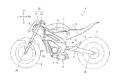
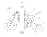
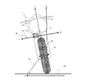
図1は、本発明の実施形態に係る鞍乗型電動車両1を示す側面図である。図1に示す例では、鞍乗型電動車両1は、オンロード型の電動二輪車である。なお、本発明の実施形態に係る鞍乗型電動車両は、ここで例示するオンロード型の電動二輪車に限定されない。本発明の実施形態に係る鞍乗型電動車両は、例えばオフロード型等の他の型式の電動二輪車であってもよい。また、本発明の実施形態に係る鞍乗型電動車両は、乗員が跨って乗車する任意の車両を意味し、二輪車に限定されない。本発明の実施形態に係る鞍乗型電動車両は、三輪車(LMW)等であってもよく、ATV(All Terrain Vehicle)等の他の鞍乗型電動車両であってもよい。   FIG. 1 is a side view showing a saddle riding type electric vehicle 1 according to an embodiment of the present invention. In the example shown in FIG. 1, the saddle riding type electric vehicle 1 is an on-road type electric motorcycle. The straddle-type electric vehicle according to the embodiment of the present invention is not limited to the on-road electric motorcycle exemplified here. The straddle-type electric vehicle according to the embodiment of the present invention may be another type of electric motorcycle such as an off-road type. The straddle-type electric vehicle according to the embodiment of the present invention means an arbitrary vehicle on which an occupant rides and is not limited to a two-wheeled vehicle. The straddle-type electric vehicle according to the embodiment of the present invention may be a tricycle (LMW) or the like, or may be another straddle-type electric vehicle such as an ATV (All Terrain Vehicle).

図1に示すように、電動二輪車1は、フレーム10、ステアリング装置20、前輪2および後輪3を備える。電動二輪車1は、さらに、後輪3を駆動するための動力を発生させる電動モータ5と、電動モータ5に電力を供給するバッテリ4と、電動モータ5の動作を制御するMCU(Motor Control Unit)30とを備える。電動モータ5は、バッテリ4から供給される電力により駆動力を生じ、後輪3を駆動する。   As shown in FIG. 1, the electric motorcycle 1 includes a frame 10, a steering device 20, a front wheel 2 and a rear wheel 3. The electric motorcycle 1 further includes an electric motor 5 that generates power for driving the rear wheels 3, a battery 4 that supplies electric power to the electric motor 5, and an MCU (Motor Control Unit) that controls the operation of the electric motor 5. 30. The electric motor 5 generates a driving force by the electric power supplied from the battery 4 and drives the rear wheel 3.

本実施形態のフレーム10はモノコックフレームである。モノコック構造は、骨組みの代わりに車両のボディ(外皮)に強度および剛性を持たせた構造であり、応力外皮構造とも称される。フレーム10は、その最前部に位置するヘッドパイプ11と、ヘッドパイプ11の後方に位置するバッテリケース14およびモータケース13と、バッテリケース14の後方に位置する収納ケース15とを含む。モータケース13はバッテリケース14の下方に位置する。収納ケース15の上方に、乗員が着座するシート6が配置されている。収納ケース15は、乗員の荷物を収納する。乗員の荷物は、例えば、乗員の携帯品、電動二輪車1の取扱説明書および車検証である。収納ケース15は、バッテリケース14に隣接して配置される。   The frame 10 of this embodiment is a monocoque frame. The monocoque structure is a structure in which strength and rigidity are given to a vehicle body (outer skin) instead of a framework, and is also referred to as a stress outer skin structure. The frame 10 includes a head pipe 11 located at the foremost part thereof, a battery case 14 and a motor case 13 located behind the head pipe 11, and a storage case 15 located behind the battery case 14. The motor case 13 is located below the battery case 14. A seat 6 on which an occupant sits is disposed above the storage case 15. The storage case 15 stores a passenger's luggage. The passenger's baggage is, for example, the passenger's personal belongings, the instruction manual for the electric motorcycle 1, and the vehicle verification. The storage case 15 is disposed adjacent to the battery case 14.

フレーム10の一部を構成するバッテリケース14は、バッテリ4を収納する。バッテリケース14は、上面が開口した箱状であり、バッテリケース14の上面を覆うようにケースカバー12が設けられている。   A battery case 14 constituting a part of the frame 10 houses the battery 4. The battery case 14 has a box shape with an upper surface opened, and a case cover 12 is provided so as to cover the upper surface of the battery case 14.

バッテリ4は、例えばリチウムイオン電池である。本実施形態では、バッテリ4はバッテリケース14に対して着脱可能なバッテリである。本実施形態では電動二輪車1が搭載するバッテリの個数は1個であるが、搭載されるバッテリ4の個数は1個に限定されず、複数(つまり2つ以上)のバッテリ4がバッテリケース14に収納されてもよい。   The battery 4 is a lithium ion battery, for example. In the present embodiment, the battery 4 is a battery that can be attached to and detached from the battery case 14. In the present embodiment, the number of batteries mounted on the electric motorcycle 1 is one, but the number of mounted batteries 4 is not limited to one, and a plurality of (that is, two or more) batteries 4 are attached to the battery case 14. It may be stored.

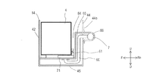
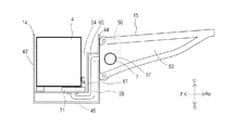
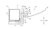
外部充電装置の給電コネクタが着脱可能な受電コネクタ7が、電動二輪車1の側面に配置されている。バッテリ4の充電は、受電コネクタ7に外部充電装置の給電コネクタを接続して行うことができる。   A power receiving connector 7 to which a power feeding connector of the external charging device can be attached and detached is disposed on the side surface of the electric motorcycle 1. The battery 4 can be charged by connecting a power feeding connector of an external charging device to the power receiving connector 7.

モータケース13は、電動モータ5を含む後輪駆動系を収容する。電動モータ5によって駆動される後輪3は、リアアーム8に取り付けられている。後輪3には、車軸29が挿通されている。後輪3は、リアアーム8に、車軸29周りに回転可能に取り付けられている。電動モータ5で発生した動力は、不図示のベルトまたはチェーンによって後輪3に伝達される。   The motor case 13 houses a rear wheel drive system including the electric motor 5. The rear wheel 3 driven by the electric motor 5 is attached to the rear arm 8. An axle 29 is inserted through the rear wheel 3. The rear wheel 3 is attached to the rear arm 8 so as to be rotatable around the axle 29. The power generated by the electric motor 5 is transmitted to the rear wheel 3 by a belt or chain (not shown).

モータケース13の下方に、リアサスペンション9が配置されている。リアサスペンション9の前端はモータケース13に支持されている。リアサスペンション9の後端は、例えばリンク機構を介してリアアーム8に連結される。   A rear suspension 9 is disposed below the motor case 13. The front end of the rear suspension 9 is supported by the motor case 13. The rear end of the rear suspension 9 is connected to the rear arm 8 via, for example, a link mechanism.

ステアリング装置20は、ヘッドパイプ11に挿通されたステアリングシャフト21と、ステアリングシャフト21の上端に取り付けられたハンドル22とを含む。ステアリング装置20は、フレーム10に対してステアリング軸線(ステアリングシャフト21の中心軸)周りに回動可能である。ステアリング装置20の回動(ステアリングシャフト21の回転)により、前輪2が転舵される。   The steering device 20 includes a steering shaft 21 inserted through the head pipe 11 and a handle 22 attached to the upper end of the steering shaft 21. The steering device 20 is rotatable around a steering axis (the central axis of the steering shaft 21) with respect to the frame 10. The front wheel 2 is steered by the rotation of the steering device 20 (rotation of the steering shaft 21).

ステアリング装置20にはフロントサスペンション25が連結されている。フロントサスペンション25は、ステアリングシャフト21に対してストローク方向に移動可能に取り付けられている。前輪2には、車軸28が挿通されている。前輪2は、フロントサスペンション25に、車軸28周りに回転可能に取り付けられている。   A front suspension 25 is connected to the steering device 20. The front suspension 25 is attached to the steering shaft 21 so as to be movable in the stroke direction. An axle 28 is inserted through the front wheel 2. The front wheel 2 is attached to the front suspension 25 so as to be rotatable around the axle 28.

本実施形態では、外部充電装置の給電コネクタが着脱可能な受電コネクタ7は、互いに隣接するバッテリケース14と収納ケース15との境界に配置される。なお、当然ながら受電コネクタ7は三次元的な寸法を有しているので、受電コネクタ7全体が、バッテリケース14と収納ケース15との厳密な意味での境界に位置するわけではない。本願明細書において、「互いに隣接するバッテリケース14と収納ケース15との境界に受電コネクタ7が配置される」とは、受電コネクタ7がバッテリケース14と収納ケース15との境界を含む領域あるいは境界近傍領域に位置していることを意味している。言い換えると、「互いに隣接するバッテリケース14と収納ケース15との境界に受電コネクタ7が配置される」とは、受電コネクタ7がその境界に十分に近接していることを意味している。   In the present embodiment, the power receiving connector 7 to which the power supply connector of the external charging device can be attached and detached is disposed at the boundary between the battery case 14 and the storage case 15 adjacent to each other. Naturally, since the power receiving connector 7 has a three-dimensional dimension, the entire power receiving connector 7 is not positioned at the strict boundary between the battery case 14 and the storage case 15. In this specification, “the power receiving connector 7 is disposed at the boundary between the battery case 14 and the storage case 15 adjacent to each other” means that the power receiving connector 7 includes an area or boundary including the boundary between the battery case 14 and the storage case 15. It means that it is located in the neighborhood area. In other words, “the power receiving connector 7 is disposed at the boundary between the battery case 14 and the storage case 15 adjacent to each other” means that the power receiving connector 7 is sufficiently close to the boundary.

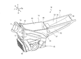
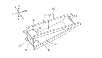
図2は、電動二輪車1が備えるフレーム10を示す斜視図である。本実施形態のフレーム10はモノコックフレームであり、フレーム10は金属製である。フレーム10の材料は、例えばアルミニウム、鉄、マグネシウム、およびそれらの合金などであるが、それらに限定されない。また、フレーム10の材料として、炭素繊維強化プラスチック(Carbon Fiber Reinforced Plastic)等のカーボン複合材料が用いられてもよい。   FIG. 2 is a perspective view showing a frame 10 provided in the electric motorcycle 1. The frame 10 of this embodiment is a monocoque frame, and the frame 10 is made of metal. The material of the frame 10 is, for example, aluminum, iron, magnesium, and alloys thereof, but is not limited thereto. Further, a carbon composite material such as a carbon fiber reinforced plastic may be used as the material of the frame 10.

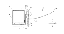
フレーム10は、バッテリ4を収納するバッテリケース14と、バッテリケース14の下方に位置するモータケース13とを有している。バッテリケース14は上部が開口した箱状であり、バッテリケース14の開口を覆うケースカバー12(図1)が設けられている。ケースカバー12はバッテリケース14の開口に対応したサイズを有し、バッテリケース14はケースカバー12によって閉じられる。バッテリ4は電動二輪車1に対して着脱可能であり、使用者は、ケースカバー12を開くことで、バッテリケース14にバッテリ4を収納したり、バッテリケース14からバッテリ4を取り出したりすることができる。   The frame 10 includes a battery case 14 that houses the battery 4 and a motor case 13 that is positioned below the battery case 14. The battery case 14 has a box shape with an open top, and a case cover 12 (FIG. 1) is provided to cover the opening of the battery case 14. The case cover 12 has a size corresponding to the opening of the battery case 14, and the battery case 14 is closed by the case cover 12. The battery 4 can be attached to and detached from the electric motorcycle 1, and the user can store the battery 4 in the battery case 14 or take out the battery 4 from the battery case 14 by opening the case cover 12. .

バッテリケース14は、その前面を構成する前壁42と、その左右の側面を構成する側壁43と、その後面を構成する後壁44とを有している。これら壁42、43、44はバッテリ4を取り囲んでバッテリ4を保護する。バッテリ4を収納するバッテリケース14は、モノコックフレーム10の一部を構成する。これにより、電動二輪車1の剛性を確保しつつ、軽量化を図ったり、車幅の増大を抑えたりすることができる。また、電動二輪車1がモノコックフレームを採用することにより、部品点数を低減することができる。   The battery case 14 has a front wall 42 that forms the front surface, a side wall 43 that forms the left and right side surfaces, and a rear wall 44 that forms the rear surface. These walls 42, 43, 44 surround the battery 4 and protect the battery 4. A battery case 14 that houses the battery 4 constitutes a part of the monocoque frame 10. As a result, it is possible to reduce the weight or suppress an increase in the vehicle width while securing the rigidity of the electric motorcycle 1. Moreover, the number of parts can be reduced because the electric motorcycle 1 employs a monocoque frame.

バッテリケース14は、ステアリングシャフト21(図1)を支持するヘッドパイプ11の後方に位置している。ヘッドパイプ11は、フレーム前部16と一体に成型されている。フレーム前部16は、ボルトなどの締結部材が差し込まれる穴17を有しており、締結部材によってフレーム前部16とバッテリケース14とが互いに固定される。この構造によれば、フレーム前部16の形状やヘッドパイプ11の角度などが異なる複数種類の車両モデルにおいて、共通のバッテリケース14を採用することができる。なお、フレーム前部16とバッテリケース14は、溶接により接続されてもよい。また、フレーム前部16とバッテリケース14は一体に成型されていてもよい。   The battery case 14 is located behind the head pipe 11 that supports the steering shaft 21 (FIG. 1). The head pipe 11 is formed integrally with the frame front portion 16. The frame front portion 16 has a hole 17 into which a fastening member such as a bolt is inserted, and the frame front portion 16 and the battery case 14 are fixed to each other by the fastening member. According to this structure, a common battery case 14 can be employed in a plurality of types of vehicle models in which the shape of the frame front portion 16 and the angle of the head pipe 11 are different. The frame front portion 16 and the battery case 14 may be connected by welding. Further, the frame front portion 16 and the battery case 14 may be integrally molded.

モータケース13の前方には放熱用のフィン18が設けられている。モータケース13内の電動モータ5(図1)から発生した熱は、フィン18を介して外部へ効率的に放出することができる。フィン18は、モータケース13とは別々に成型されてもよいし、一体に成型されてもよい。   A heat dissipation fin 18 is provided in front of the motor case 13. The heat generated from the electric motor 5 (FIG. 1) in the motor case 13 can be efficiently released to the outside through the fins 18. The fins 18 may be molded separately from the motor case 13 or may be molded integrally.

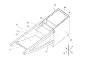
図2に示すように、フレーム10はバッテリケース14の後方に配置された収納ケース15を備える。収納ケース15は、バッテリケース14の後方に固定される。収納ケース15は、シート6(図1)の下方に位置し、シート6を支持するリアフレームの役割を果たす。   As shown in FIG. 2, the frame 10 includes a storage case 15 disposed behind the battery case 14. The storage case 15 is fixed behind the battery case 14. The storage case 15 is positioned below the seat 6 (FIG. 1) and serves as a rear frame that supports the seat 6.

収納ケース15は、その左右の側面を構成する側壁53と、その底面を構成する底壁55をと備える。底壁55は、後壁44から後方に向かって徐々に斜め上方向に延びている。底壁55の後端には収納ケース15の後壁54が設けられる。   The storage case 15 includes a side wall 53 that forms the left and right side surfaces, and a bottom wall 55 that forms the bottom surface. The bottom wall 55 gradually extends obliquely upward from the rear wall 44 toward the rear. A rear wall 54 of the storage case 15 is provided at the rear end of the bottom wall 55.

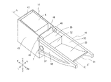
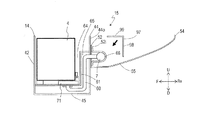
図3は、バッテリケース14および収納ケース15を左斜め後方から見た斜視図である。バッテリケース14の後壁44からは、バッテリケース14と収納ケース15とを接続して固定するための接続部46が後方へ突出している。この接続部46と収納ケース15とは、例えばボルトなどの締結部材で固定される。また、接続部46と収納ケース15とは溶接等、他の接続手法により固定されてもよい。収納ケース15の前方部には収納ケース15の前壁52が設けられる。前壁52の上端から前方へ向かって上壁56が設けられる。車両左側の側壁53の前方部には、受電コネクタ7が配置される穴57が設けられる。   FIG. 3 is a perspective view of the battery case 14 and the storage case 15 as viewed obliquely from the left rear. A connection portion 46 for connecting and fixing the battery case 14 and the storage case 15 protrudes rearward from the rear wall 44 of the battery case 14. The connecting portion 46 and the storage case 15 are fixed by a fastening member such as a bolt, for example. Moreover, the connection part 46 and the storage case 15 may be fixed by other connection methods such as welding. A front wall 52 of the storage case 15 is provided at the front portion of the storage case 15. An upper wall 56 is provided from the upper end of the front wall 52 toward the front. A hole 57 in which the power receiving connector 7 is disposed is provided in a front portion of the side wall 53 on the left side of the vehicle.

収納ケース15の前壁52、側壁53、後壁54、底壁55で囲まれたスペースが収納スペースとなる。また、図3の例では、上壁56の上方において上壁56と側壁53とで囲まれたスペースも収納ケース15の収納スペースとなる。収納ケース15がリアフレームの役割を果たすことで、シート6の下方に収納スペースを確保することができる。収納ケース15は上部が開口した箱状であり、収納ケース15の上方に位置するシート6(図1)が収納ケース15の開口を覆う収納ケースカバーとなる。収納ケース15はシート6によって閉じられる。乗員は例えばシート6を取り外すことで、収納ケース15に対して荷物の出し入れを行うことができる。   A space surrounded by the front wall 52, the side wall 53, the rear wall 54, and the bottom wall 55 of the storage case 15 is a storage space. In the example of FIG. 3, the space surrounded by the upper wall 56 and the side wall 53 above the upper wall 56 is also a storage space of the storage case 15. Since the storage case 15 serves as a rear frame, a storage space can be secured below the seat 6. The storage case 15 has a box shape with an open top, and the sheet 6 (FIG. 1) located above the storage case 15 serves as a storage case cover that covers the opening of the storage case 15. The storage case 15 is closed by the sheet 6. For example, the occupant can remove and load the seat 6 with respect to the storage case 15.

収納ケース15の前壁52、側壁53、後壁54、底壁55、上壁56は、一体に成型され得るが、別々に形成されてもよい。例えば、それらの壁同士はボルトなどの締結部材で固定されてもよいし、溶接により固定されてもよい。   The front wall 52, the side wall 53, the rear wall 54, the bottom wall 55, and the upper wall 56 of the storage case 15 can be integrally formed, but may be formed separately. For example, these walls may be fixed with fastening members such as bolts, or may be fixed by welding.

なお、収納ケース15とリアフレームとは別部材として電動二輪車1に設けられてもよい。例えば、電動二輪車1は、バッテリケース14から後方に延びるレール状のリアフレームを備え、そのリアフレームに箱状の収納ケース15を配置してもよい。この場合も収納ケース15はバッテリケース14に隣接して配置される。また、収納ケース15とリアフレームとが別部材である場合は、レール状のリアフレームはモノコックフレームの一部を構成していなくてもよい。   The storage case 15 and the rear frame may be provided in the electric motorcycle 1 as separate members. For example, the electric motorcycle 1 may include a rail-shaped rear frame extending rearward from the battery case 14, and a box-shaped storage case 15 may be disposed on the rear frame. Also in this case, the storage case 15 is disposed adjacent to the battery case 14. Further, when the storage case 15 and the rear frame are separate members, the rail-shaped rear frame may not constitute a part of the monocoque frame.

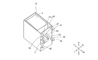
図4は、バッテリケース14を左斜め後方から見た斜視図である。図5は、図3に示すA−A’線に沿ったバッテリケース14の断面図である。   FIG. 4 is a perspective view of the battery case 14 as viewed obliquely from the rear left. FIG. 5 is a cross-sectional view of the battery case 14 along the line A-A ′ shown in FIG. 3.

バッテリケース14に収納されたバッテリ4と受電コネクタ7とは、ハーネス60を介して接続される。分かり易く説明するために、図5の断面図にはハーネス60を図示している。ハーネス60の一部は、バッテリケース14の後壁44および底壁45に沿って配置されており、コネクタ71を介してバッテリ4と接続される。   The battery 4 housed in the battery case 14 and the power receiving connector 7 are connected via a harness 60. For easy understanding, the harness 60 is shown in the sectional view of FIG. A part of the harness 60 is disposed along the rear wall 44 and the bottom wall 45 of the battery case 14, and is connected to the battery 4 via the connector 71.

バッテリケース14は、バッテリ4を収納するバッテリ収納スペース64と、ハーネス60の一部を収納するハーネス収納スペース65とを隔てる壁61を有する。壁61は、後壁44および底壁45に沿って延びており、後壁44および底壁45と壁61との間のハーネス収納スペース65にハーネス60が配置される。コネクタ71は壁61に設けられ、ハーネス60とバッテリ4とを接続する。   The battery case 14 has a wall 61 that separates a battery storage space 64 for storing the battery 4 and a harness storage space 65 for storing a part of the harness 60. The wall 61 extends along the rear wall 44 and the bottom wall 45, and the harness 60 is disposed in the harness storage space 65 between the rear wall 44 and the bottom wall 45 and the wall 61. The connector 71 is provided on the wall 61 and connects the harness 60 and the battery 4.

バッテリケース14の後壁44には穴47が設けられており、ハーネス60はその穴47を通って、バッテリケース14の外部へ延びる。外部へ延びたハーネス60は、接続部材63を介して受電コネクタ7と接続される。接続部材63は例えばコネクタである。   A hole 47 is provided in the rear wall 44 of the battery case 14, and the harness 60 extends to the outside of the battery case 14 through the hole 47. The harness 60 extending to the outside is connected to the power receiving connector 7 via the connection member 63. The connection member 63 is a connector, for example.

受電コネクタ7は、バッテリケース14の後壁44の外側44oに取り付けられる。後壁44の外側44oは、バッテリケース14の収納ケース15と向かい合う面である。この例では、受電コネクタ7は、U字型の取付け金具66を用いて外側44oに取り付けられる。U字型の取付け金具66は、例えばボルトなどの締結部材で後壁44の外表面に固定されるが、溶接により固定されてもよい。図示する例のように、取付け金具66を介してバッテリケース14に取り付けられた受電コネクタ7と、バッテリケース14との間には隙間が空いているが、そのような隙間が空いた形態も受電コネクタ7がバッテリケース14に取り付けられていることを意味する。   The power receiving connector 7 is attached to the outer side 44 o of the rear wall 44 of the battery case 14. An outer side 44 o of the rear wall 44 is a surface facing the storage case 15 of the battery case 14. In this example, the power receiving connector 7 is attached to the outer side 44o using a U-shaped attachment fitting 66. The U-shaped mounting bracket 66 is fixed to the outer surface of the rear wall 44 by a fastening member such as a bolt, but may be fixed by welding. As shown in the example, there is a gap between the power receiving connector 7 attached to the battery case 14 via the mounting bracket 66 and the battery case 14. This means that the connector 7 is attached to the battery case 14.

図6は、収納ケース15を左斜め前方から見た斜視図である。収納ケース15の前部には、前壁52(図3)、側壁53、底壁55、上壁56で囲まれたスペース51が設けられている。バッテリケース14と収納ケース15とが固定された状態では、バッテリケース14の外部へ延びたハーネス60および受電コネクタ7はこのスペース51に位置する。   FIG. 6 is a perspective view of the storage case 15 as viewed obliquely from the left front. A space 51 surrounded by a front wall 52 (FIG. 3), a side wall 53, a bottom wall 55, and an upper wall 56 is provided at the front portion of the storage case 15. In a state where the battery case 14 and the storage case 15 are fixed, the harness 60 and the power receiving connector 7 extending to the outside of the battery case 14 are located in the space 51.

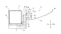
図7および図8は、バッテリケース14と収納ケース15とが固定された状態を示す図である。図7は、図3に示すA−A’線に沿ったバッテリケース14の断面と、収納ケース15の側面を示している。図8は、図3に示すA−A’線に沿ったバッテリケース14および収納ケース15の断面を示している。   7 and 8 are views showing a state in which the battery case 14 and the storage case 15 are fixed. FIG. 7 shows a cross section of the battery case 14 along the line A-A ′ shown in FIG. 3 and a side surface of the storage case 15. FIG. 8 shows a cross section of the battery case 14 and the storage case 15 along the line A-A ′ shown in FIG. 3.

収納ケース15の前部はバッテリケース14の後壁44と隣接している。本実施形態におけるバッテリケース14と収納ケース15との境界の一例として、境界50を一点鎖線で示している。この例では、前壁52、側壁53、底壁55および上壁56は、バッテリケース14の後壁44と隣接している。受電コネクタ7は、互いに隣接するバッテリケース14と収納ケース15との境界に位置する。この例では、バッテリケース14と収納ケース15との境界に位置するスペース51に受電コネクタ7が配置される。   The front portion of the storage case 15 is adjacent to the rear wall 44 of the battery case 14. As an example of the boundary between the battery case 14 and the storage case 15 in the present embodiment, the boundary 50 is indicated by a one-dot chain line. In this example, the front wall 52, the side wall 53, the bottom wall 55, and the upper wall 56 are adjacent to the rear wall 44 of the battery case 14. The power receiving connector 7 is located at the boundary between the battery case 14 and the storage case 15 adjacent to each other. In this example, the power receiving connector 7 is disposed in a space 51 located at the boundary between the battery case 14 and the storage case 15.

本実施形態の電動二輪車1では、バッテリケース14に隣接して収納ケース15を配置することで、収納スペースを確保している。そして、互いに隣接するバッテリケース14と収納ケース15との境界に受電コネクタ7を配置し、受電コネクタ7の配置スペースを確保した。また、互いに隣接するバッテリケース14と収納ケース15との境界に受電コネクタ7を配置することで、バッテリ4から近い位置に受電コネクタ7を配置することができる。このため、バッテリ4から離れた位置に受電コネクタ7を配置する構成と比べて、バッテリ4と受電コネクタ7とを接続するハーネス60を短くすることができる。ハーネス60が短いことにより、ハーネス60の配置に必要なスペースを小さくできる。従って、電動二輪車1に受電コネクタ7およびハーネス60を設けても、電動二輪車1の他の部品のレイアウトに影響を及ぼしにくい。また、ハーネス60はデータ通信用の信号線を含む。ハーネス60が短いことで、そのような信号線へのノイズの混入を抑制することができる。また、ハーネス60が短いことで、電動二輪車1の重量およびコストの増加を抑制することができる。   In the electric motorcycle 1 of the present embodiment, a storage space is secured by arranging the storage case 15 adjacent to the battery case 14. Then, the power receiving connector 7 is arranged at the boundary between the battery case 14 and the storage case 15 adjacent to each other, and the arrangement space for the power receiving connector 7 is secured. Further, by arranging the power receiving connector 7 at the boundary between the battery case 14 and the storage case 15 adjacent to each other, the power receiving connector 7 can be arranged at a position close to the battery 4. For this reason, compared with the structure which arrange | positions the power receiving connector 7 in the position away from the battery 4, the harness 60 which connects the battery 4 and the power receiving connector 7 can be shortened. Since the harness 60 is short, the space required for the arrangement of the harness 60 can be reduced. Therefore, even if the power receiving connector 7 and the harness 60 are provided in the electric motorcycle 1, the layout of other components of the electric motorcycle 1 is hardly affected. The harness 60 includes a data communication signal line. Since the harness 60 is short, mixing of noise into such a signal line can be suppressed. Further, since the harness 60 is short, an increase in the weight and cost of the electric motorcycle 1 can be suppressed.

バッテリケース14の後壁44の穴47(図4)から受電コネクタ7へ延びるハーネス60は、収納ケース15の前壁52、側壁53、底壁55および上壁56と、バッテリケース14の後壁44とに囲まれている。バッテリケース14から延びるハーネス60が外部に露出しないので、外部衝撃からハーネス60を保護することができる。   The harness 60 extending from the hole 47 (FIG. 4) of the rear wall 44 of the battery case 14 to the power receiving connector 7 includes the front wall 52, the side wall 53, the bottom wall 55 and the upper wall 56 of the storage case 15, and the rear wall of the battery case 14. 44. Since the harness 60 extending from the battery case 14 is not exposed to the outside, the harness 60 can be protected from an external impact.

図9は、バッテリケース14および収納ケース15を右斜め後方から見た斜視図である。車両右側の側壁53には、図2に示すような穴57は設けられていない。また、図3に示すように、車両左側の側壁53の穴57には受電コネクタ7が配置される。このように、バッテリケース14から延びるハーネス60は外部に露出しない。   FIG. 9 is a perspective view of the battery case 14 and the storage case 15 as viewed from the right rear side. The side wall 53 on the right side of the vehicle is not provided with a hole 57 as shown in FIG. As shown in FIG. 3, the power receiving connector 7 is disposed in the hole 57 in the side wall 53 on the left side of the vehicle. Thus, the harness 60 extending from the battery case 14 is not exposed to the outside.

また、この例では、図4に示すように、受電コネクタ7とハーネス60とがバッテリケース14という同じ部材に取り付けられる。これにより、電動二輪車1の製造時に受電コネクタ7とハーネス60の接続および取り付けを容易に行うことができる。   In this example, as shown in FIG. 4, the power receiving connector 7 and the harness 60 are attached to the same member as the battery case 14. Thereby, the connection and attachment of the power receiving connector 7 and the harness 60 can be easily performed at the time of manufacturing the electric motorcycle 1.

本実施形態では、バッテリケース14および収納ケース15は導電性材料で形成されている。バッテリケース14および収納ケース15の材料は、例えばアルミニウム、鉄、マグネシウム、およびそれらの合金などであるが、それらに限定されない。ハーネス60を囲む収納ケース15の前壁52、側壁53、底壁55および上壁56とバッテリケース14の後壁44は、導電性を有する。導電性を有するバッテリケース14および収納ケース15がフレーム10の一部を構成することで、バッテリケース14および収納ケース15はボディアースとしての役割を果たすことができる。また、金属材料等の導電性材料は一般に熱伝導性が高いことから、バッテリケース14およびハーネス60で発生した熱は、それら導電性材料を伝達させて、効率良く外部へ放出することができる。   In the present embodiment, the battery case 14 and the storage case 15 are formed of a conductive material. The materials of the battery case 14 and the storage case 15 are, for example, aluminum, iron, magnesium, and alloys thereof, but are not limited thereto. The front wall 52, the side wall 53, the bottom wall 55 and the upper wall 56 of the storage case 15 surrounding the harness 60 and the rear wall 44 of the battery case 14 are conductive. Since the battery case 14 and the storage case 15 having conductivity constitute a part of the frame 10, the battery case 14 and the storage case 15 can serve as a body ground. In addition, since conductive materials such as metal materials generally have high thermal conductivity, heat generated in the battery case 14 and the harness 60 can be efficiently discharged to the outside by transmitting the conductive materials.

上述したように、バッテリケース14は、バッテリ4を収納するバッテリ収納スペース64と、ハーネス60の一部を収納するハーネス収納スペース65とが壁61により隔てられている。これにより、バッテリ4に対する作業からハーネス60を保護することができる。例えば、バッテリケース14に対してバッテリ4を着脱するときに、バッテリ4がハーネス60に衝突することを防止することができる。   As described above, in the battery case 14, the battery storage space 64 that stores the battery 4 and the harness storage space 65 that stores a part of the harness 60 are separated by the wall 61. Thereby, the harness 60 can be protected from work on the battery 4. For example, the battery 4 can be prevented from colliding with the harness 60 when the battery 4 is attached to or detached from the battery case 14.

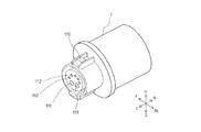
図10は、バッテリケース14内に配置されたコネクタ71とバッテリ4とを示す斜視図である。分かり易く説明するために、バッテリ4の内部を透かして示している。バッテリ4をバッテリケース14内に装着したとき、コネクタ71とバッテリ4に設けられたコネクタ72とが接続される。   FIG. 10 is a perspective view showing the connector 71 and the battery 4 arranged in the battery case 14. For easy understanding, the inside of the battery 4 is shown in a watermark. When the battery 4 is mounted in the battery case 14, the connector 71 and the connector 72 provided on the battery 4 are connected.

バッテリ4は、バッテリモジュール81と、把持部82と、バッテリマネージメントシステム(BMS)83と、表示部89とを備える。バッテリモジュール81は複数のセルを含んでいる。BMS83は、マイクロコンピュータ85と、スイッチ87とを備える。マイクロコンピュータ85は、バッテリ4の充電および放電等の各種動作を制御する。スイッチ87は、各種動作時の電流のオン/オフを切り替える。表示部89はバッテリ4の状態を表示する。表示部89は、例えば、バッテリの残量、バッテリ状態が正常であるか異常であるか等を表示する。   The battery 4 includes a battery module 81, a gripping part 82, a battery management system (BMS) 83, and a display part 89. The battery module 81 includes a plurality of cells. The BMS 83 includes a microcomputer 85 and a switch 87. The microcomputer 85 controls various operations such as charging and discharging of the battery 4. The switch 87 switches on / off current during various operations. The display unit 89 displays the state of the battery 4. The display unit 89 displays, for example, the remaining battery level, whether the battery state is normal or abnormal, and the like.

コネクタ72は、充電用の電流が供給される電極端子75と、充電に関するデータの送受信を行うための信号端子76とを備える。コネクタ71は、充電用の電流が供給される電極端子73と、充電に関するデータの送受信を行うための信号端子74とを備える。バッテリケース14に対し、バッテリ4はスライド式に挿入および取り外しが可能になっている。乗員は、バッテリ4の把持部82を手で握り、バッテリ4を上方へスライドさせることで電動二輪車1からバッテリ4を取り外すことができる。電動二輪車1にバッテリ4を装着するときは、バッテリ4をバッテリケース14内に挿入して下方へスライドさせることで装着される。このスライドさせて装着したときに、コネクタ71とコネクタ72とが接続される。すなわち、電極端子73と電極端子75とが接続され、信号端子74と信号端子76とが接続される。バッテリ4の充放電は、バッテリ4が接続されたコネクタ71を介して行われる。バッテリ4の充電時は、外部充電装置の給電コネクタを電動二輪車1の受電コネクタ7に接続することで、受電コネクタ7、ハーネス60、コネクタ71、コネクタ72を介して外部充電装置からバッテリ4のバッテリモジュール81に電力が供給される。充電の制御は、電動二輪車1のBMS83と外部充電装置との間で充電に関するデータの送受信を行うことで行われる。電動二輪車1の走行時、バッテリ4から出力された電流は、コネクタ71、MCU30、図示しないハーネス等を介して電動モータ5に入力される。   The connector 72 includes an electrode terminal 75 to which a charging current is supplied and a signal terminal 76 for transmitting and receiving data related to charging. The connector 71 includes an electrode terminal 73 to which a charging current is supplied and a signal terminal 74 for transmitting and receiving data related to charging. The battery 4 can be inserted into and removed from the battery case 14 in a sliding manner. The occupant can remove the battery 4 from the electric motorcycle 1 by grasping the grip 82 of the battery 4 with a hand and sliding the battery 4 upward. When the battery 4 is attached to the electric motorcycle 1, it is attached by inserting the battery 4 into the battery case 14 and sliding it downward. The connector 71 and the connector 72 are connected when mounted by sliding. That is, the electrode terminal 73 and the electrode terminal 75 are connected, and the signal terminal 74 and the signal terminal 76 are connected. Charging / discharging of the battery 4 is performed via a connector 71 to which the battery 4 is connected. When charging the battery 4, the power supply connector of the external charging device is connected to the power receiving connector 7 of the electric motorcycle 1, so that the battery 4 is connected to the battery 4 from the external charging device via the power receiving connector 7, the harness 60, the connector 71, and the connector 72. Power is supplied to the module 81. Charging control is performed by transmitting and receiving data related to charging between the BMS 83 of the electric motorcycle 1 and the external charging device. When the electric motorcycle 1 travels, the current output from the battery 4 is input to the electric motor 5 via the connector 71, the MCU 30, a harness (not shown), and the like.

図8に示すように、本実施形態では、コネクタ71はバッテリケース14の前壁42よりもバッテリケース14の後壁44に近い位置に配置される。例えば、コネクタ71の中心部は、バッテリケース14の中心部よりも後方に位置する。ハーネス60が接続される受電コネクタ7は、バッテリケース14とその後方に配置された収納ケース15との境界に配置されている。このため、ハーネス60が接続されるコネクタ71を、バッテリケース14の後方に配置することにより、ハーネス60をより短くすることができる。   As shown in FIG. 8, in the present embodiment, the connector 71 is disposed at a position closer to the rear wall 44 of the battery case 14 than to the front wall 42 of the battery case 14. For example, the central portion of the connector 71 is located behind the central portion of the battery case 14. The power receiving connector 7 to which the harness 60 is connected is disposed at the boundary between the battery case 14 and the storage case 15 disposed behind the battery case 14. For this reason, the harness 60 can be made shorter by arranging the connector 71 to which the harness 60 is connected behind the battery case 14.

図11は、充電ステーション(充電スタンドとも称される)を用いた電動二輪車1の充電の形態を示す図である。充電ステーション100は、外部充電器の一例であり、例えば駐輪場に設置される。充電ステーション100から延びる充電ケーブル101の一端には給電コネクタ130が設けられている。   FIG. 11 is a diagram illustrating a form of charging of the electric motorcycle 1 using a charging station (also referred to as a charging station). The charging station 100 is an example of an external charger, and is installed in, for example, a bicycle parking lot. A power feeding connector 130 is provided at one end of the charging cable 101 extending from the charging station 100.

本実施形態のバッテリ4は、電動二輪車1に対して着脱可能であり、バッテリ4を電動二輪車1から取り外して充電を行うことができる。しかし、外出先などでは、バッテリ4を電動二輪車1から取り外すことなく充電を行うことが可能な方が便利である。この例では、バッテリ4を電動二輪車1から取り外すことなく、給電コネクタ130を電動二輪車1の受電コネクタ7に挿入することで、充電ケーブル101を介して充電ステーション100から電動二輪車1のバッテリ4に電力が供給されて充電が行われる。充電の制御は、充電ステーション100とバッテリ4のBMS83との間で充電に関するデータの送受信を行うことで行われる。   The battery 4 of this embodiment is detachable from the electric motorcycle 1 and can be charged by removing the battery 4 from the electric motorcycle 1. However, it is more convenient to be able to charge the battery 4 without removing the battery 4 from the electric motorcycle 1 when away from home. In this example, the power feeding connector 130 is inserted into the power receiving connector 7 of the electric motorcycle 1 without removing the battery 4 from the electric motorcycle 1, whereby electric power is supplied from the charging station 100 to the battery 4 of the electric motorcycle 1 through the charging cable 101. Is supplied for charging. Charging control is performed by transmitting and receiving data related to charging between the charging station 100 and the BMS 83 of the battery 4.

図12は、受電コネクタ7を示す斜視図である。図13(a)は、給電コネクタ130を示す正面図であり、図13(b)は、給電コネクタ130を示す側面図である。   FIG. 12 is a perspective view showing the power receiving connector 7. FIG. 13A is a front view showing the power supply connector 130, and FIG. 13B is a side view showing the power supply connector 130.

受電コネクタ7は、充電用の電流が供給される電極端子111と、充電に関するデータの送受信を行うための信号端子112を備える。給電コネクタ130は、充電用の電流を供給する電極端子131と、充電に関するデータの送受信を行うための信号端子132を備える。   The power receiving connector 7 includes an electrode terminal 111 to which a charging current is supplied and a signal terminal 112 for transmitting and receiving data related to charging. The power supply connector 130 includes an electrode terminal 131 that supplies a charging current and a signal terminal 132 that transmits and receives data related to charging.

電極端子および信号端子の数および種類は任意である。例えば、送受信するデータの形態に応じて信号端子は様々な数に設定され得る。また、バッテリ4から外部充電器への放電が可能な形態においては、受電コネクタ7および給電コネクタ130に放電用の電極端子が設けられていてもよい。また、データの送受信は、無線通信(例えば、近距離無線通信等)により行ってもよい。   The number and type of electrode terminals and signal terminals are arbitrary. For example, the signal terminals can be set to various numbers depending on the form of data to be transmitted / received. Moreover, in the form in which discharge from the battery 4 to the external charger is possible, the electrode connector for discharging may be provided in the power receiving connector 7 and the power feeding connector 130. Data transmission / reception may be performed by wireless communication (for example, short-range wireless communication).

この例では、給電コネクタ130が有する電極端子131および信号端子132はオス端子であり、受電コネクタ7が有する電極端子111および信号端子112はメス端子である。オス端子とメス端子との関係は逆であってもよい。   In this example, the electrode terminal 131 and the signal terminal 132 included in the power feeding connector 130 are male terminals, and the electrode terminal 111 and the signal terminal 112 included in the power receiving connector 7 are female terminals. The relationship between the male terminal and the female terminal may be reversed.

給電コネクタ130を受電コネクタ7に差し込むと、給電コネクタ130の電極端子131が受電コネクタ7の電極端子111に差し込まれて接続される。また、給電コネクタ130の信号端子132が受電コネクタ7の信号端子112に差し込まれて接続される。   When the power feeding connector 130 is inserted into the power receiving connector 7, the electrode terminal 131 of the power feeding connector 130 is inserted into and connected to the electrode terminal 111 of the power receiving connector 7. In addition, the signal terminal 132 of the power supply connector 130 is inserted and connected to the signal terminal 112 of the power receiving connector 7.

給電コネクタ130は爪部139を備え、受電コネクタ7は突起部119を備える。給電コネクタ130が受電コネクタ7に接続されると、給電コネクタ130の爪部139は受電コネクタ7の突起部119と係合してロックされる。   The power feeding connector 130 includes a claw 139, and the power receiving connector 7 includes a protrusion 119. When the power feeding connector 130 is connected to the power receiving connector 7, the claw portion 139 of the power feeding connector 130 engages with the protrusion 119 of the power receiving connector 7 and is locked.

給電コネクタ130は、爪部139と連結されたおよび押しボタン138を備える。受電コネクタ7から給電コネクタ130を取り外すとき、ユーザが押しボタン138を押すと、押しボタン138が図13(b)における下方へ移動するのに連動して爪部139は上方へ移動する。これにより、爪部139と突起部119とが離れてロックは解除される。受電コネクタ7に給電コネクタ130を差し込むときとは逆方向に給電コネクタ130を移動させることで、受電コネクタ7にから給電コネクタ130を取り外すことができる。   The power supply connector 130 includes a push button 138 connected to the claw portion 139. When the user pushes the push button 138 when removing the power supply connector 130 from the power receiving connector 7, the claw portion 139 moves upward in conjunction with the push button 138 moving downward in FIG. Thereby, the nail | claw part 139 and the projection part 119 leave | separate and a lock | rock is cancelled | released. The power supply connector 130 can be removed from the power reception connector 7 by moving the power supply connector 130 in a direction opposite to that when the power supply connector 130 is inserted into the power reception connector 7.

受電コネクタ7はその端子部分を覆うカバーを有していてもよい。充電時以外は各端子をカバーで覆うことにより、雨や埃の侵入および漏電を防止することができる。また、給電コネクタ130にもカバーが設けられていてもよい。   The power receiving connector 7 may have a cover that covers the terminal portion. Covering each terminal with a cover except during charging can prevent rain and dust from entering and leakage. Further, the power supply connector 130 may be provided with a cover.

図11を参照して、受電コネクタ7は、電動二輪車1の高い位置に配置される。例えば、受電コネクタ7は、前輪2の車軸28および後輪3の車軸29のそれぞれよりも高い位置に配置される。受電コネクタ7が電動二輪車1の高い位置に配置されていることにより、受電コネクタ7に対して給電コネクタ130を抜き差しするとき、使用者は低くかがむ必要がないため、抜き差しを容易に行うことができる。   Referring to FIG. 11, the power receiving connector 7 is arranged at a high position of the electric motorcycle 1. For example, the power receiving connector 7 is disposed at a position higher than each of the axle 28 of the front wheel 2 and the axle 29 of the rear wheel 3. Since the power receiving connector 7 is disposed at a high position in the electric motorcycle 1, when the power feeding connector 130 is inserted into and removed from the power receiving connector 7, the user does not need to bend down and can be easily inserted and removed. .

上記の説明では、外部充電器は充電ステーション100であったが、家庭用充電器であってもよい。この場合、家庭用充電器は充電ケーブル101および給電コネクタ130を備え、その給電コネクタ130を電動二輪車1の受電コネクタ7に挿入することで、バッテリ4の充電を行うことができる。   In the above description, the external charger is the charging station 100, but it may be a household charger. In this case, the household charger includes the charging cable 101 and the power feeding connector 130, and the battery 4 can be charged by inserting the power feeding connector 130 into the power receiving connector 7 of the electric motorcycle 1.

上述した例では、図8に示すように、受電コネクタ7はバッテリケース14の後壁44に取り付けられていたが、別の部材に取り付けられてもよい。例えば、受電コネクタ7は収納ケース15に取り付けられてもよい。   In the example described above, the power receiving connector 7 is attached to the rear wall 44 of the battery case 14 as shown in FIG. 8, but it may be attached to another member. For example, the power receiving connector 7 may be attached to the storage case 15.

図14は、受電コネクタ7が収納ケース15に取り付けられた形態におけるバッテリケース14および収納ケース15を示す断面図である。図14に示すバッテリケース14および収納ケース15の断面は、図8と同様に図3に示すA−A’線に沿った断面に対応している。図14に示す例では、受電コネクタ7は、収納ケース15の前壁52の前方の外側52oに取り付けられている。この例では、受電コネクタ7は、U字型の取付け金具66を用いて外側52oに取り付けられる。   FIG. 14 is a cross-sectional view showing the battery case 14 and the storage case 15 in a form in which the power receiving connector 7 is attached to the storage case 15. The cross sections of the battery case 14 and the storage case 15 shown in FIG. 14 correspond to the cross section along the line A-A ′ shown in FIG. In the example shown in FIG. 14, the power receiving connector 7 is attached to the outer side 52 o in front of the front wall 52 of the storage case 15. In this example, the power receiving connector 7 is attached to the outer side 52o using a U-shaped attachment fitting 66.

このように、収納ケース15の外側52oに受電コネクタ7を取り付けることで、互いに隣接するバッテリケース14と収納ケース15との境界に受電コネクタ7を配置することができる。この例では、バッテリケース14と収納ケース15との境界に位置するスペース51に受電コネクタ7が配置される。   In this manner, by attaching the power receiving connector 7 to the outer side 52o of the storage case 15, the power receiving connector 7 can be disposed at the boundary between the battery case 14 and the storage case 15 adjacent to each other. In this example, the power receiving connector 7 is disposed in a space 51 located at the boundary between the battery case 14 and the storage case 15.

また、受電コネクタ7は、上壁56の下側の外側56oまたは底壁55の上側の外側55oに取り付けてもよい。この場合も、互いに隣接するバッテリケース14と収納ケース15との境界に受電コネクタ7を配置することができる。   The power receiving connector 7 may be attached to the outer side 56o on the lower side of the upper wall 56 or the outer side 55o on the upper side of the bottom wall 55. Also in this case, the power receiving connector 7 can be arranged at the boundary between the battery case 14 and the storage case 15 adjacent to each other.

バッテリケース14の後壁44の穴47(図4)から受電コネクタ7へ延びるハーネス60を囲む部材を、バッテリケース14および収納ケース15とは別に設けてもよい。図15は、バッテリケース14および収納ケース15を示す断面図である。図15に示すバッテリケース14および収納ケース15の断面は、図3に示すA−A’線に沿った断面に対応している。この例では収納ケース15の前壁52および上壁56の代わりに、カバー90が配置される。カバー90は、受電コネクタ7の上方を覆う上壁96と、受電コネクタ7の後方を覆う後壁94と、受電コネクタ7の下方を覆う底壁95とを備える。   A member surrounding the harness 60 extending from the hole 47 (FIG. 4) of the rear wall 44 of the battery case 14 to the power receiving connector 7 may be provided separately from the battery case 14 and the storage case 15. FIG. 15 is a cross-sectional view showing the battery case 14 and the storage case 15. The cross sections of the battery case 14 and the storage case 15 shown in FIG. 15 correspond to the cross section along the line A-A ′ shown in FIG. 3. In this example, a cover 90 is disposed instead of the front wall 52 and the upper wall 56 of the storage case 15. The cover 90 includes an upper wall 96 that covers the upper side of the power receiving connector 7, a rear wall 94 that covers the rear side of the power receiving connector 7, and a bottom wall 95 that covers the lower side of the power receiving connector 7.

バッテリケース14の後壁44から受電コネクタ7へ延びるハーネス60は、これらカバー90の上壁96、後壁94、底壁95と、収納ケース15の側壁53によって囲まれる。バッテリケース14から延びるハーネス60が外部に露出しないので、外部衝撃からハーネス60を保護することができる。   The harness 60 extending from the rear wall 44 of the battery case 14 to the power receiving connector 7 is surrounded by the upper wall 96, the rear wall 94, the bottom wall 95, and the side wall 53 of the storage case 15. Since the harness 60 extending from the battery case 14 is not exposed to the outside, the harness 60 can be protected from an external impact.

カバー90は、受電コネクタ7の前方を覆っていてもよい。図16は、受電コネクタ7の前方を覆うカバー90を示す断面図である。この例では、カバー90は、受電コネクタ7の前方を覆う前壁92を備える。受電コネクタ7はこの前壁92に取り付けられる。受電コネクタ7が取り付けられたカバー90は、ボルトなどの締結部材を用いて、バッテリケース14の後壁44に固定される。これにより、互いに隣接するバッテリケース14と収納ケース15との境界に受電コネクタ7を配置することができる。この例では、バッテリケース14と収納ケース15との境界に位置するスペース91に受電コネクタ7が配置される。   The cover 90 may cover the front of the power receiving connector 7. FIG. 16 is a cross-sectional view showing a cover 90 that covers the front of the power receiving connector 7. In this example, the cover 90 includes a front wall 92 that covers the front of the power receiving connector 7. The power receiving connector 7 is attached to the front wall 92. The cover 90 to which the power receiving connector 7 is attached is fixed to the rear wall 44 of the battery case 14 using a fastening member such as a bolt. Thereby, the power receiving connector 7 can be disposed at the boundary between the battery case 14 and the storage case 15 adjacent to each other. In this example, the power receiving connector 7 is arranged in a space 91 located at the boundary between the battery case 14 and the storage case 15.

受電コネクタ7が収納ケース15に取り付けられる形態において、受電コネクタ7は前壁52の内側に取り付けられてもよい。図17は、受電コネクタ7が収納ケース15に取り付けられた形態におけるバッテリケース14および収納ケース15を示す断面図である。図17に示す収納ケース15の前壁52は、図8に示す前壁52よりも前方に位置し、図17に示す収納ケース15は上壁56を備えていない。図17に示す例では受電コネクタ7は、U字型の取付け金具66を用いて、収納ケース15の前壁52の内側52iに取り付けられる。ここでは、バッテリケース14と対面する前壁52をバッテリケース14と収納ケース15との境界部分とする。この境界部分である前壁52の内側52iに取り付けられた受電コネクタ7は、互いに隣接するバッテリケース14と収納ケース15との境界に配置されているといえる。   In the form in which the power receiving connector 7 is attached to the storage case 15, the power receiving connector 7 may be attached to the inside of the front wall 52. FIG. 17 is a cross-sectional view showing the battery case 14 and the storage case 15 in a form in which the power receiving connector 7 is attached to the storage case 15. The front wall 52 of the storage case 15 shown in FIG. 17 is positioned in front of the front wall 52 shown in FIG. 8, and the storage case 15 shown in FIG. In the example shown in FIG. 17, the power receiving connector 7 is attached to the inner side 52 i of the front wall 52 of the storage case 15 using a U-shaped attachment fitting 66. Here, the front wall 52 facing the battery case 14 is a boundary portion between the battery case 14 and the storage case 15. It can be said that the power receiving connector 7 attached to the inner side 52i of the front wall 52 which is the boundary portion is arranged at the boundary between the battery case 14 and the storage case 15 adjacent to each other.

収納ケース15は、前壁52の内側52iに取り付けられた受電コネクタ7を覆うカバー97を有する。図18は、受電コネクタ7を覆うカバー97を示す断面図である。カバー97は、受電コネクタ7の上方を覆う上壁99と、受電コネクタ7の後方を覆う後壁98とを備える。   The storage case 15 has a cover 97 that covers the power receiving connector 7 attached to the inner side 52 i of the front wall 52. FIG. 18 is a cross-sectional view showing a cover 97 that covers the power receiving connector 7. The cover 97 includes an upper wall 99 that covers the upper side of the power receiving connector 7 and a rear wall 98 that covers the rear side of the power receiving connector 7.

バッテリケース14の後壁44から延びて受電コネクタ7に接続されるハーネス60は、これらカバー97の上壁99、後壁98と、収納ケース15の側壁53、底壁55によって囲まれる。バッテリケース14から延びるハーネス60が外部に露出しないので、外部衝撃からハーネス60を保護することができる。また、収納ケース15に対して荷物を出し入れする作業からハーネス60を保護することができる。例えば、出し入れする荷物がハーネス60に衝突しないように保護することができる。   The harness 60 that extends from the rear wall 44 of the battery case 14 and is connected to the power receiving connector 7 is surrounded by the upper wall 99 and the rear wall 98 of the cover 97, the side wall 53, and the bottom wall 55 of the storage case 15. Since the harness 60 extending from the battery case 14 is not exposed to the outside, the harness 60 can be protected from an external impact. In addition, the harness 60 can be protected from the work of taking in and out the luggage with respect to the storage case 15. For example, it is possible to protect the loaded / unloaded luggage from colliding with the harness 60.

受電コネクタ7がバッテリケース14に取り付けられる形態において、受電コネクタ7は後壁44の内側に取り付けられてもよい。図19は、受電コネクタ7がバッテリケース14に取り付けられた形態におけるバッテリケース14および収納ケース15を示す断面図である。図19に示す例では受電コネクタ7は、U字型の取付け金具66を用いて、バッテリケース14の後壁44の内側44iに取り付けられる。ここでは、収納ケース15と対面する後壁44をバッテリケース14と収納ケース15との境界部分とする。この境界部分である後壁44の内側44iに取り付けられた受電コネクタ7は、互いに隣接するバッテリケース14と収納ケース15との境界に配置されている。   In the form in which the power receiving connector 7 is attached to the battery case 14, the power receiving connector 7 may be attached to the inside of the rear wall 44. FIG. 19 is a cross-sectional view showing the battery case 14 and the storage case 15 in a form in which the power receiving connector 7 is attached to the battery case 14. In the example shown in FIG. 19, the power receiving connector 7 is attached to the inner side 44 i of the rear wall 44 of the battery case 14 using a U-shaped attachment fitting 66. Here, the rear wall 44 facing the storage case 15 is a boundary portion between the battery case 14 and the storage case 15. The power receiving connector 7 attached to the inner side 44i of the rear wall 44, which is the boundary portion, is disposed at the boundary between the battery case 14 and the storage case 15 adjacent to each other.

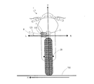
次に、電動二輪車1に配置される受電コネクタ7の向きを説明する。図20および図21は、電動二輪車1を後方から見た背面図である。図21は、電動二輪車1を駐輪している状態を示している。   Next, the direction of the power receiving connector 7 disposed in the electric motorcycle 1 will be described. 20 and 21 are rear views of the electric motorcycle 1 as viewed from the rear. FIG. 21 shows a state where the electric motorcycle 1 is parked.

図20は、電動二輪車1が直立している状態を示している。例えば、電動二輪車1が平坦な路面150を直線走行しているときがこの直立している状態に該当する。受電コネクタ7の充電口115は、電動二輪車1の側面に位置している。この例では、充電口115は、電動二輪車1の左側面に位置している。充電口115の向きは、例えば、受電コネクタ7に対する給電コネクタ130の挿抜方向と平行である。充電口115は、水平方向Hに対して斜め上方向を向いている。水平方向Hは、平坦な路面150に平行な方向である。直線走行している電動二輪車1の車幅方向LRおよび車軸29は、水平方向Hに平行である。   FIG. 20 shows a state where the electric motorcycle 1 is upright. For example, when the electric motorcycle 1 is traveling straight on a flat road surface 150, this state corresponds to the upright state. The charging port 115 of the power receiving connector 7 is located on the side surface of the electric motorcycle 1. In this example, the charging port 115 is located on the left side surface of the electric motorcycle 1. The direction of the charging port 115 is parallel to, for example, the insertion / extraction direction of the power supply connector 130 with respect to the power receiving connector 7. The charging port 115 faces obliquely upward with respect to the horizontal direction H. The horizontal direction H is a direction parallel to the flat road surface 150. The vehicle width direction LR and the axle 29 of the electric motorcycle 1 running in a straight line are parallel to the horizontal direction H.

図21を参照して、電動二輪車1はサイドスタンド151を備える。この例では、サイドスタンド151は、電動二輪車1の左側方に配置される。サイドスタンド151は、駐輪時に電動二輪車1を傾斜した状態で支持する。例えば、サイドスタンド151は、電動二輪車1が平坦な路面150上で駐輪しているときに、平坦な路面150に垂直な方向Vに対して、電動二輪車1の高さ方向Uが左に傾斜した状態で、電動二輪車1を支持する。このように電動二輪車1が傾斜してサイドスタンド151に支持されている状態において、受電コネクタ7の充電口115は、水平方向Hに対して平行または斜め上方向を向く。   Referring to FIG. 21, the electric motorcycle 1 includes a side stand 151. In this example, the side stand 151 is disposed on the left side of the electric motorcycle 1. The side stand 151 supports the electric motorcycle 1 in an inclined state during parking. For example, in the side stand 151, when the electric motorcycle 1 is parked on the flat road surface 150, the height direction U of the electric motorcycle 1 is inclined to the left with respect to the direction V perpendicular to the flat road surface 150. The electric motorcycle 1 is supported in the state. Thus, in a state where the electric motorcycle 1 is inclined and supported by the side stand 151, the charging port 115 of the power receiving connector 7 faces parallel or obliquely upward with respect to the horizontal direction H.

斜め上方向を向く受電コネクタ7の充電口115の角度の例を説明する。図20を参照して、車両の左方向Lと受電コネクタ7の充電口115の向き121とがなす角度(仰角)をθ1とする。ここで、車両の左方向Lは、直立状態の車両の中央部Oから水平方向Hに平行に左へ延びる方向である。充電口115の向き121は、車両の内から外へ向かう方向であり、受電コネクタ7が有する電極端子111および信号端子112が延びる方向に平行である。図21を参照して、電動二輪車1が平坦な路面150上で駐輪している時に、垂直方向Vに対して、電動二輪車1の高さ方向Uが左に傾斜する角度(傾斜角)をθ2とする。このとき、仰角θ1は、傾斜角θ2以上となる。言い換えると、受電コネクタ7の充電口115が斜め上方向に傾斜する仰角θ1は、駐輪時の電動二輪車1の傾斜角θ2以上である。 An example of the angle of the charging port 115 of the power receiving connector 7 facing obliquely upward will be described. Referring to FIG. 20, an angle (elevation angle) formed by left direction L of the vehicle and direction 121 of charging port 115 of power receiving connector 7 is defined as θ 1 . Here, the left direction L of the vehicle is a direction extending to the left in parallel with the horizontal direction H from the central portion O of the vehicle in an upright state. The direction 121 of the charging port 115 is the direction from the inside of the vehicle to the outside, and is parallel to the direction in which the electrode terminal 111 and the signal terminal 112 of the power receiving connector 7 extend. Referring to FIG. 21, when the electric motorcycle 1 is parked on a flat road surface 150, an angle (inclination angle) at which the height direction U of the electric motorcycle 1 inclines to the left with respect to the vertical direction V. Let θ 2 . At this time, the elevation angle θ 1 is equal to or greater than the inclination angle θ 2 . In other words, the elevation angle θ 1 at which the charging port 115 of the power receiving connector 7 is inclined obliquely upward is equal to or greater than the inclination angle θ 2 of the electric motorcycle 1 when parked.

このように、サイドスタンド151を用いて電動二輪車1を傾斜させて駐輪している状態でも、受電コネクタ7の充電口115は水平方向Hに対して平行または斜め上方向を向いている。言い換えると、駐輪時に電動二輪車1が傾斜していたとしても、受電コネクタ7に対する給電コネクタ130の挿抜方向は、水平方向Hに平行または斜め上方向となる。外部充電装置の給電コネクタ130を受電コネクタ7に対して抜き差しするときに、使用者は受電コネクタ7を下から見上げる必要がないため、給電コネクタ130の抜き差しを容易に行うことができる。   In this manner, even when the electric motorcycle 1 is parked while being tilted using the side stand 151, the charging port 115 of the power receiving connector 7 faces parallel or obliquely upward with respect to the horizontal direction H. In other words, even if the electric motorcycle 1 is inclined during parking, the insertion / extraction direction of the power supply connector 130 with respect to the power receiving connector 7 is parallel to the horizontal direction H or obliquely upward. When the power supply connector 130 of the external charging device is connected to or disconnected from the power reception connector 7, the user does not need to look up the power reception connector 7 from below, so that the power supply connector 130 can be easily connected or disconnected.

上述の仰角θ1の範囲は、例えば、傾斜角θ2以上、傾斜角θ2+20°以下であるが、これに限定されない。例えば、仰角θ1の大きさが傾斜角θ2+10°であるとき、駐輪時に電動二輪車1が傾斜していたとしても、受電コネクタ7に対する給電コネクタ130の挿抜方向は、水平方向Hに対して10°上方向を向く。 The range of the above-described elevation angle θ 1 is, for example, the inclination angle θ 2 or more and the inclination angle θ 2 + 20 ° or less, but is not limited thereto. For example, when the elevation angle θ 1 is the inclination angle θ 2 + 10 °, even if the electric motorcycle 1 is inclined during parking, the insertion / extraction direction of the power supply connector 130 with respect to the power receiving connector 7 is relative to the horizontal direction H. Facing 10 ° upward.

なお、上述の実施形態の説明では、受電コネクタ7は電動二輪車1の左側に配置されたが、右側に配置されてもよい。この場合も、互いに隣接するバッテリケース14と収納ケース15との境界に受電コネクタ7を配置することで、上記と同様の効果が得られる。   In the description of the above-described embodiment, the power receiving connector 7 is disposed on the left side of the electric motorcycle 1, but may be disposed on the right side. Also in this case, the same effect as described above can be obtained by arranging the power receiving connector 7 at the boundary between the battery case 14 and the storage case 15 adjacent to each other.

また、上述の実施形態の説明では、電動モータ5の駆動力が伝達される駆動輪は後輪3であったが、電動二輪車1の形態に応じて、前輪2に電動モータ5の駆動力が伝達されてもよい。また、前輪2および後輪3の両方に駆動力が伝達されてもよい。   In the above description of the embodiment, the driving wheel to which the driving force of the electric motor 5 is transmitted is the rear wheel 3, but the driving force of the electric motor 5 is applied to the front wheel 2 according to the form of the electric motorcycle 1. May be communicated. Further, the driving force may be transmitted to both the front wheel 2 and the rear wheel 3.

以上、本発明の実施形態を説明した。上述の実施形態の説明は、本発明の例示であり、本発明を限定するものではない。また、上述の実施形態で説明した各構成要素を適宜組み合わせた実施形態も可能である。本発明は、特許請求の範囲またはその均等の範囲において、改変、置き換え、付加および省略などが可能である。   The embodiments of the present invention have been described above. The above description of the embodiment is an exemplification of the present invention and does not limit the present invention. In addition, an embodiment in which the components described in the above embodiment are appropriately combined is possible. The present invention can be modified, replaced, added and omitted within the scope of the claims and the equivalents thereof.

本発明は、外部充電器の給電コネクタを車両本体に接続してバッテリの充電を行う鞍乗型電動車両の分野において特に有用である。   The present invention is particularly useful in the field of a straddle-type electric vehicle that charges a battery by connecting a power supply connector of an external charger to the vehicle body.

1 電動二輪車(鞍乗型電動車両)
2 前輪
3 後輪
4 バッテリ
5 電動モータ
6 シート
7 受電コネクタ
8 リアアーム
9 リアサスペンション
10 フレーム
11 ヘッドパイプ
12 ケースカバー
13 モータケース
14 バッテリケース
15 収納ケース
16 フレーム前部
17 穴
18 フィン
20 ステアリング装置
21 ステアリングシャフト
22 ハンドル
25 フロントサスペンション
28、29 車軸
30 MCU
42 バッテリケースの前壁
43 バッテリケースの側壁
44 バッテリケースの後壁
44o バッテリケースの後壁の外側
45 底壁
46 接続部
47 穴
50 境界
51 スペース
52 前壁
52i 前壁の内側
52o 前壁の外側
53 側壁
54 後壁
55 底壁
56 上壁
57 穴
60 ハーネス
61 壁
63 接続部材
64 バッテリ収納スペース
65 ハーネス収納スペース
66 取付け金具
71、72 コネクタ
73、75 電極端子
74、76 信号端子
81 バッテリモジュール
82 把持部
83 BMS
85 マイクロコンピュータ
87 スイッチ
89 表示部
100 充電ステーション
101 充電ケーブル
111、131 電極端子
112、132 信号端子
115 充電口
119 突起部
121 充電口の向き
130 給電コネクタ
138 押しボタン
139 爪部
150 路面
151 サイドスタンド
1 Electric motorcycle (saddle-type electric vehicle)
2 front wheel 3 rear wheel 4 battery 5 electric motor 6 seat 7 power receiving connector 8 rear arm 9 rear suspension 10 frame 11 head pipe 12 case cover 13 motor case 14 battery case 15 storage case 16 frame front portion 17 hole 18 fin 20 steering device 21 steering Shaft 22 Handle 25 Front suspension 28, 29 Axle 30 MCU
42 Front Wall of Battery Case 43 Side Wall of Battery Case 44 Rear Wall of Battery Case 44o Outside of Rear Wall of Battery Case 45 Bottom Wall 46 Connection 47 Hole 50 Boundary 51 Space 52 Front Wall 52i Inside Front Wall 52o Outside Front Wall 53 Side wall 54 Rear wall 55 Bottom wall 56 Top wall 57 Hole 60 Harness 61 Wall 63 Connection member 64 Battery storage space 65 Harness storage space 66 Mounting bracket 71, 72 Connector 73, 75 Electrode terminal 74, 76 Signal terminal 81 Battery module 82 Grasping Part 83 BMS
85 Microcomputer 87 Switch 89 Display unit 100 Charging station 101 Charging cable 111, 131 Electrode terminal 112, 132 Signal terminal 115 Charging port 119 Projection unit 121 Direction of charging port 130 Feeding connector 138 Push button 139 Claw unit 150 Road surface 151 Side stand

Claims (14)

バッテリと、
前記バッテリから供給される電力により駆動力を生じる電動モータと、
ヘッドパイプを有するフレームと、
前記ヘッドパイプよりも後方に配置され、前記バッテリを収納するバッテリケースと、
前記バッテリケースよりも後方に配置され、荷物を収納する収納ケースと、
外部充電装置の給電コネクタを着脱可能な受電コネクタと、
前記バッテリと前記受電コネクタとを接続するハーネスと、
を備え、
前記バッテリケースと前記収納ケースとは互いに隣接して配置されており、
前記受電コネクタは、前記バッテリケースと前記収納ケースとの境界に配置されている、鞍乗型電動車両。
Battery,
An electric motor that generates a driving force by electric power supplied from the battery;
A frame having a head pipe;
A battery case disposed behind the head pipe and storing the battery;
A storage case that is arranged behind the battery case and stores luggage;
A power receiving connector to which the power supply connector of the external charging device can be attached and detached;
A harness connecting the battery and the power receiving connector;
With
The battery case and the storage case are arranged adjacent to each other,
The power receiving connector is a straddle-type electric vehicle disposed at a boundary between the battery case and the storage case.
前記受電コネクタは、前記バッテリケースに取り付けられている、請求項1に記載の鞍乗型電動車両。   The straddle-type electric vehicle according to claim 1, wherein the power receiving connector is attached to the battery case. 前記受電コネクタは、前記収納ケースに取り付けられている、請求項1に記載の鞍乗型電動車両。   The straddle-type electric vehicle according to claim 1, wherein the power receiving connector is attached to the storage case. 前記ハーネスの少なくとも一部は、前記バッテリケースと前記収納ケースとに囲まれている、請求項1から3の何れかに記載の鞍乗型電動車両。   The straddle-type electric vehicle according to any one of claims 1 to 3, wherein at least a part of the harness is surrounded by the battery case and the storage case. 前記収納ケースは、前記ハーネスの少なくとも一部を覆うカバーを備える、請求項1から4のいずれかに記載の鞍乗型電動車両。   The straddle-type electric vehicle according to any one of claims 1 to 4, wherein the storage case includes a cover that covers at least a part of the harness. 前記収納ケースにおける前記ハーネスの少なくとも一部を囲む部分は、導電性材料を含む、請求項4または5に記載の鞍乗型電動車両。   The straddle-type electric vehicle according to claim 4 or 5, wherein a portion surrounding at least a part of the harness in the storage case includes a conductive material. 前記バッテリケースは、導電性材料を含む、請求項1から6の何れかに記載の鞍乗型電動車両。   The straddle-type electric vehicle according to any one of claims 1 to 6, wherein the battery case includes a conductive material. 前記フレームはモノコックフレームであり、
前記バッテリケースは、前記モノコックフレームの一部を構成する、請求項1から7の何れかに記載の鞍乗型電動車両。
The frame is a monocoque frame;
The straddle-type electric vehicle according to any one of claims 1 to 7, wherein the battery case constitutes a part of the monocoque frame.
乗員が座るシートをさらに備え、
前記収納ケースは、前記シートの下方に配置される、請求項1から8の何れかに記載の鞍乗型電動車両。
It is further equipped with a seat for the passenger
The straddle-type electric vehicle according to any one of claims 1 to 8, wherein the storage case is disposed below the seat.
前輪および後輪をさらに備え、
前記受電コネクタは、前記前輪および前記後輪のそれぞれの車軸より高い位置に配置されている、請求項1から9の何れかに記載の鞍乗型電動車両。
Further comprising front and rear wheels,
The straddle-type electric vehicle according to any one of claims 1 to 9, wherein the power receiving connector is disposed at a position higher than the axles of the front wheels and the rear wheels.
前記受電コネクタの充電口は、前記鞍乗型電動車両の側面に位置しており、
前記鞍乗型電動車両が直立している状態において、前記受電コネクタの充電口は、水平方向に対して斜め上方向を向いている、請求項1から10の何れかに記載の鞍乗型電動車両。
The charging port of the power receiving connector is located on a side surface of the saddle type electric vehicle,
The straddle-type electric vehicle according to any one of claims 1 to 10, wherein the charging port of the power receiving connector faces obliquely upward with respect to a horizontal direction in a state where the straddle-type electric vehicle is upright. vehicle.
駐輪時に前記鞍乗型電動車両を傾斜した状態で支持するサイドスタンドをさらに備え、
前記鞍乗型電動車両が傾斜してサイドスタンドに支持されている状態において、前記受電コネクタの充電口は、水平方向に対して平行または斜め上方向を向いている、請求項11に記載の鞍乗型電動車両。
Further comprising a side stand that supports the saddle-type electric vehicle in a tilted state when parking,
The saddle riding according to claim 11, wherein the charging port of the power receiving connector faces parallel or obliquely upward with respect to a horizontal direction in a state where the saddle riding type electric vehicle is inclined and supported by a side stand. Type electric vehicle.
前記バッテリケースは、前記バッテリを収納するバッテリ収納スペースと、前記ハーネスの少なくとも一部を収納するハーネス収納スペースとを隔てる壁を有する、請求項1から12のいずれかに記載の鞍乗型電動車両。   The straddle-type electric vehicle according to any one of claims 1 to 12, wherein the battery case has a wall separating a battery storage space for storing the battery and a harness storage space for storing at least a part of the harness. . 前記バッテリは、前記鞍乗型電動車両に対して着脱可能であり、
前記バッテリ収納スペースと前記ハーネス収納スペースとを分ける前記壁に設けられ、前記バッテリと前記ハーネスとを接続するコネクタをさらに備え、
前記コネクタは、前記バッテリケースの前壁よりも前記バッテリケースの後壁に近い位置に配置されている、請求項13に記載の鞍乗型電動車両。
The battery is detachable from the saddle riding type electric vehicle,
Provided on the wall separating the battery storage space and the harness storage space, further comprising a connector for connecting the battery and the harness;
The straddle-type electric vehicle according to claim 13, wherein the connector is disposed closer to a rear wall of the battery case than to a front wall of the battery case.
JP2016081212A 2016-04-14 2016-04-14 Saddle-riding type electric vehicle Pending JP2017190071A (en)

Priority Applications (1)

Application Number Priority Date Filing Date Title
JP2016081212A JP2017190071A (en) 2016-04-14 2016-04-14 Saddle-riding type electric vehicle

Applications Claiming Priority (1)

Application Number Priority Date Filing Date Title
JP2016081212A JP2017190071A (en) 2016-04-14 2016-04-14 Saddle-riding type electric vehicle

Publications (1)

Publication Number Publication Date
JP2017190071A true JP2017190071A (en) 2017-10-19

Family

ID=60084557

Family Applications (1)

Application Number Title Priority Date Filing Date
JP2016081212A Pending JP2017190071A (en) 2016-04-14 2016-04-14 Saddle-riding type electric vehicle

Country Status (1)

Country Link
JP (1) JP2017190071A (en)

Cited By (2)

* Cited by examiner, † Cited by third party
Publication number Priority date Publication date Assignee Title
WO2020066208A1 (en) * 2018-09-28 2020-04-02 本田技研工業株式会社 Saddle-type electric vehicle
JP2021160602A (en) * 2020-03-31 2021-10-11 本田技研工業株式会社 Saddle-riding type vehicle

Cited By (5)

* Cited by examiner, † Cited by third party
Publication number Priority date Publication date Assignee Title
WO2020066208A1 (en) * 2018-09-28 2020-04-02 本田技研工業株式会社 Saddle-type electric vehicle
CN112752706A (en) * 2018-09-28 2021-05-04 本田技研工业株式会社 Saddle-ride type electric vehicle
JPWO2020066208A1 (en) * 2018-09-28 2021-08-30 本田技研工業株式会社 Saddle-type electric vehicle
JP2021160602A (en) * 2020-03-31 2021-10-11 本田技研工業株式会社 Saddle-riding type vehicle
JP7060643B2 (en) 2020-03-31 2022-04-26 本田技研工業株式会社 Saddle-type vehicle

Similar Documents

Publication Publication Date Title
US10611425B2 (en) Saddle-type electric vehicle
US9545968B2 (en) Saddle-type electric vehicle
US9327586B2 (en) Saddle-type electric vehicle
JP5595228B2 (en) Electric vehicle
US9346421B2 (en) Saddle-type electric vehicle
US9660236B2 (en) Battery and saddle-type electric vehicle equipped therewith
JP5474737B2 (en) Saddle riding type electric vehicle
EP2641822B1 (en) Electric saddled vehicle, and drive device for electric vehicle
JP5525998B2 (en) Saddle riding type electric vehicle
JP6971386B2 (en) Electric vehicle
JP6950081B2 (en) Electric vehicle
CN113365907B (en) Saddle-ride type electric vehicle
CN111989260B (en) Saddle-ride type electric vehicle
TWI697438B (en) Saddle type electric vehicle
JP2017190071A (en) Saddle-riding type electric vehicle
JPWO2019194009A1 (en) Electric vehicle
JP5492742B2 (en) Cooling duct routing structure for saddle-ride type electric vehicles
JP7097979B2 (en) Saddle-type vehicle
JPWO2020066208A1 (en) Saddle-type electric vehicle
US20230026390A1 (en) Straddled electric vehicle
WO2024058264A1 (en) Saddle-type vehicle
JP6833052B2 (en) Saddle-type electric vehicle
JP6825122B2 (en) Saddle-type electric vehicle
JP6852174B2 (en) Saddle-type electric vehicle