JP2017184784A - Pachinko game machine - Google Patents
Pachinko game machine Download PDFInfo
- Publication number
- JP2017184784A JP2017184784A JP2016073710A JP2016073710A JP2017184784A JP 2017184784 A JP2017184784 A JP 2017184784A JP 2016073710 A JP2016073710 A JP 2016073710A JP 2016073710 A JP2016073710 A JP 2016073710A JP 2017184784 A JP2017184784 A JP 2017184784A
- Authority
- JP
- Japan
- Prior art keywords
- game
- ball
- payout
- main game
- flag
- Prior art date
- Legal status (The legal status is an assumption and is not a legal conclusion. Google has not performed a legal analysis and makes no representation as to the accuracy of the status listed.)
- Pending
Links
Images


Abstract
Description
ぱちんこ遊技機に関する。 It relates to pachinko machines.
近年のぱちんこ遊技機としては、遊技盤面(遊技領域)上の始動口に遊技球が入球したことを契機として所定確率の大当り抽選がなされ、当該大当り抽選に当選した場合には大当り(特別遊技)状態へと移行し、遊技盤面に備えられた大入賞口が開放して大量の賞球を獲得できるぱちんこ遊技機が主流である。また、遊技盤面(遊技領域)上の始動口等の入賞口に遊技球が入球したことを契機として賞球を獲得できるぱちんこ遊技機が主流となっている。 As a recent pachinko game machine, a big hit lottery with a predetermined probability is made when a game ball enters the starting opening on the game board surface (game area), and if the big hit lottery is won, The mainstream is pachinko gaming machines that transition to the state and can open a large winning opening provided on the game board surface to obtain a large number of prize balls. In addition, pachinko machines that can win prize balls when a game ball enters a winning opening such as a starting opening on a game board surface (game area) have become mainstream.
しかしながら、遊技盤面(遊技領域)を流下する遊技球が衝突することで遊技釘の角度が変化する等の理由により、或る入賞口への遊技球の入球効率が遊技機の出荷時に想定していた入球効率とは異なってしまうことがあり、そのような場合にも入賞口毎の入球効率がどの程度であるかを判断できないという課題が存在する。 However, due to the fact that the angle of the game nail changes due to the collision of the game balls flowing down the game board surface (game area), the efficiency of entering the game balls into a certain prize opening is assumed at the time of shipment of the game machine. In some cases, there is a problem that it is not possible to determine the degree of the entrance efficiency for each winning opening.
本態様に係るぱちんこ遊技機は、
遊技球が入球可能であり、遊技球が入球することにより賞球が払い出される複数の入賞口(例えば、主遊技始動口A10、第2主遊技始動口B10、一般入賞口P10、第1大入賞口C10、第2大入賞口C20)と、
情報を表示可能な情報表示部(例えば、演出表示装置SG、入球状態表示装置J10)と
を備え、
前記複数の入賞口(例えば、主遊技始動口A10、第2主遊技始動口B10、一般入賞口P10、第1大入賞口C10、第2大入賞口C20)への遊技球の入球を検出し得る入球判定手段(例えば、入球判定手段MJ10)と、
入球判定手段(例えば、入球判定手段MJ10)が検出した検出結果に基づき、前記複数の入賞口(例えば、第1主遊技始動口A10、第2主遊技始動口B10、一般入賞口P10、第1大入賞口C10、第2大入賞口C20)への遊技球の入球状況に基づく情報である入球状態情報を生成する入球状態情報生成手段(例えば、メンテナンスモード制御手段MO)と
を備え、
入球状態情報を保持している状況にて電源断が発生し、当該電源断から復帰した後においても、当該入球状態情報を保持し得るよう構成されている
ことを特徴とするぱちんこ遊技機である。
The pachinko gaming machine according to this aspect is
A plurality of winning holes (for example, a main game starting port A10, a second main game starting port B10, a general winning port P10, a first winning port) through which a game ball can enter and a prize ball is paid out when the game ball enters the ball Grand Prize Winner C10, Second Grand Prize Winner C20),
An information display unit capable of displaying information (for example, effect display device SG, entry state display device J10),
Detection of game balls entering the plurality of winning holes (for example, main gaming starting port A10, second main gaming starting port B10, general winning port P10, first major winning port C10, second major winning port C20) Possible entry determination means (for example, entry determination means MJ10);
Based on the detection result detected by the entrance determination means (for example, the entrance determination means MJ10), the plurality of prize winning openings (for example, the first main game starting opening A10, the second main game starting opening B10, the general winning opening P10, Entry state information generating means (for example, maintenance mode control means MO) for generating entry state information, which is information based on the state of entry of game balls into the first grand prize opening C10 and the second grand prize opening C20) With
A pachinko gaming machine configured to be able to retain the entry status information even after a power failure occurs in a situation where the entry status information is retained, and after returning from the power failure. It is.
本態様に係るぱちんこ遊技機によれば、入賞口毎の入球効率がどの程度であるかを判断できる。 According to the pachinko gaming machine according to this aspect, it is possible to determine how much the ball entry efficiency for each winning opening is.
はじめに、本明細書における各用語の意義について説明する。「入球」とは、賞球が払い出される入賞のみならず、賞球払い出しの無い「スルーチャッカー」への通過も含む。「識別情報」とは、五感(視覚、聴覚、触覚等)を通じて情報の種類を識別可能であればどのような形態でもよいが、好適には、視覚的なもの、例えば、数字、文字、図柄等の形状のあるものを挙げることができる。また、本明細書においては「識別情報」を、主遊技図柄・特別図柄(特図)や装飾図柄(装図)と呼ぶことがあるが、「特別図柄(特図)」は、主制御基板側にて表示制御される識別情報であり、「装飾図柄(装図)」は、副制御基板S側にて表示される演出としての識別情報である。「識別情報を表示可能」とは、表示方法には何ら限定されず、例えば、発光手段(例えば液晶、LED、7セグ)の発光(発光の有無だけでなく、色の違いも含む)、物理的な表示(例えば、リール帯に描かれた図柄を所定位置に停止表示する)等、を挙げることができる。「演出」とは、遊技の興趣性を高める表示内容を指し、例えば、識別情報変動・停止や予告等をはじめ、アニメーションや実写等の動画像や絵、写真、文字等の静止画像又はこれらの組み合わせを挙げることができる。「開状態、開放状態」及び「閉状態、閉鎖状態」とは、例えば、一般的な大入賞口(いわゆる、アタッカー)の構成においては、開状態=入賞容易状態であり、閉状態=入賞非容易状態となる。また、例えば、遊技盤(遊技者側)から突き出した状態(以下、進出状態と呼ぶことがある)と遊技盤内(遊技者側と反対側)に引っ込んだ状態(以下、退避状態と呼ぶことがある)とを採り得る構成(いわゆる、ベロ型アタッカー)においては、進出状態=入賞容易状態であり、退避状態=入賞非容易状態となる。「乱数」とは、ぱちんこ遊技機において何らかの遊技内容を決定するための抽選(電子計算機によるくじ)に使用される乱数であり、狭義の乱数の他に擬似乱数も含む(例えば、乱数としてはハード乱数、擬似乱数としてはソフト乱数)。例えば、遊技の結果に影響を与えるいわゆる「基本乱数」、具体的には、特別遊技の移行と関連した「当選乱数(当否抽選用乱数)」、識別図柄の変動態様(又は変動時間)を決定するための「変動態様決定乱数」、停止図柄を決定する「図柄決定乱数」、特別遊技後に特定遊技(例えば確率変動遊技)に移行するか否かを決定する「当り図柄決定乱数」等を挙げることができる。尚、変動態様の内容や確定識別情報の内容等を決定する際、これらすべての乱数を使用する必要はなく、互いに同一又は相違する、少なくとも一つの乱数を使用すればよい。また、本明細書では、乱数の数とか複数個の乱数、といった形で乱数を個数表示していることがあるが、乱数取得の契機となる入球口(例えば始動入球口)の一回の入球により取得された乱数を一個と称している(即ち、前記の例だと、当選乱数+変動態様決定乱数+図柄決定乱数・・・という乱数の束を一個の乱数と称している)。また、例えば、一種の乱数(例えば当選乱数)が、別種の乱数(例えば図柄決定乱数)を兼ねていてもよい。「遊技状態」とは、例えば、大入賞口が開放状態となり得る特別遊技状態、特別遊技状態への移行抽選確率が予め定められた値である非確率変動遊技状態よりも特別遊技状態への移行抽選確率が高い確率変動遊技状態、特別遊技への移行抽選契機となる始動口への入賞に対する補助が有る補助遊技状態(いわゆる、普通図柄時短状態、例えば、始動口に可変部材が取り付けられている場合では、可変部材の開放期間が長い、可変部材の開放当選確率が高い、可変部材の開放抽選の結果報知の時間が短い)、等の任意の一又は複数の組合せである。「入球状態表示」とは入球に係る情報の表示であり、所定の入球口への入球数の表示、所定の入球口への入球に基づく賞球払出数の表示、複数の入球口への累計の入球数の表示、複数の入球口への入球に基づく賞球払出数の表示、ベース値の表示、所定の遊技状態におけるベース値の表示、入球比率の表示、所定の遊技状態における入球比率の表示、役物比率の表示、連続役物比率の表示、累計の排出球数の表示、等である。「操作部材への所定操作」とは、サブ入力ボタンの押下(本例では、オフ→0.5秒以下のオン→オフとなった場合に1回押下されたと判定している)、サブ入力ボタンの長押し(本例では、オフ→10秒以上のオンとなった場合に長押しされたと判定している)、RAMクリアボタンの押下(本例では、オフ→0.5秒以下のオン→オフとなった場合に1回押下されたと判定している)、RAMクリアボタンの長押し(本例では、オフ→10秒以上のオンとなった場合に長押しされたと判定している)、発射ハンドルの操作、等である。「遊技機の背面側に設けられた操作可能な操作部材」とは、遊技者が遊技している状態においては視認不可能な背面側に設けられた部材であり、例えば、RAMクリアボタンである。「遊技機の前面側に設けられた操作可能な操作部材」とは、遊技者が遊技している状態においては視認可能な前面側に設けられた部材であり、例えば、サブ入力ボタン、発射ハンドル、である。 First, the meaning of each term in this specification will be described. “Pitching” includes not only winning a prize ball to be paid out, but also passing to a “through chucker” without winning a prize ball. The “identification information” may be in any form as long as the type of information can be identified through the five senses (visual, auditory, tactile, etc.), but is preferably visual, for example, numbers, letters, designs. The thing with the shape of etc. can be mentioned. In this specification, “identification information” may be called a main game symbol / special symbol (special symbol) or a decorative symbol (design), but the “special symbol (special symbol)” is the main control board. The “decoration pattern (drawing)” is identification information as an effect displayed on the sub-control board S side. “Displaying identification information” is not limited to a display method. For example, light emission of a light emitting means (for example, liquid crystal, LED, 7-segment) (including not only whether light is emitted but also a color difference), physical Display (for example, a symbol drawn on a reel band is stopped and displayed at a predetermined position). “Direction” refers to display content that enhances the fun of the game. For example, identification information fluctuates / stops, notices, etc., moving images such as animation and live action, still images such as pictures, photos, characters, etc. Combinations can be mentioned. “Open state, open state” and “closed state, closed state” are, for example, in the configuration of a general big prize opening (so-called attacker), open state = easy-to-win state and closed state = non-winning state Easy state. Also, for example, a state protruding from the game board (player side) (hereinafter sometimes referred to as advance state) and a state of being retracted into the game board (side opposite to the player side) (hereinafter referred to as retreat state) In a configuration (so-called velo-type attacker) that can take the following condition, the advance state = easy-to-win state and the evacuation state = non-easy-to-win state. “Random number” is a random number used in a lottery (lottery by an electronic computer) to determine some game content in a pachinko game machine, and includes a pseudo-random number in addition to a random number in a narrow sense (for example, a hard- Random numbers and soft random numbers as pseudo-random numbers). For example, the so-called “basic random numbers” that affect the outcome of the game, specifically, “winning random numbers (random numbers for success / failure lottery)” related to the transition of special games, and the variation mode (or variation time) of the identification symbol "Variation mode determination random number" for determining, "symbol determination random number" for determining a stop symbol, "hit symbol determination random number" for determining whether or not to shift to a specific game (for example, probability variation game) after a special game, etc. be able to. It is not necessary to use all these random numbers when determining the contents of the variation mode, the contents of the definite identification information, etc., and it is sufficient to use at least one random number that is the same or different from each other. Also, in this specification, the number of random numbers may be displayed in the form of the number of random numbers or a plurality of random numbers, but one entry (for example, starting entrance) that triggers the acquisition of random numbers. The random number obtained by entering the ball is referred to as one (ie, in the above example, the random number bundle of winning random number + variation mode determining random number + design determining random number... Is referred to as one random number) . Further, for example, a kind of random number (for example, a winning random number) may also serve as another kind of random number (for example, a symbol determination random number). “Game state” means, for example, a transition to a special game state rather than a non-stochastic game state in which a lottery probability for transition to a special game state or a special game state in which a special winning opening can be in an open state is a predetermined value. A probabilistic variable gaming state with a high lottery probability, an auxiliary gaming state with assistance for winning at the starting port that becomes a lottery opportunity for special games (so-called normal symbol short-time state, for example, a variable member is attached to the starting port In such a case, the variable member may be one or a combination of a plurality of combinations such as a long opening period of the variable member, a high probability of winning the opening of the variable member, and a short notification time of the result of the variable member opening lottery. “Entry status display” is a display of information related to entrance, display of the number of entrances to a predetermined entrance, display of the number of award balls paid out based on entrance to a predetermined entrance, multiple Display of the total number of entrances to the entrance of the game, display of the number of prize balls paid out based on the entrance to multiple entrances, display of the base value, display of the base value in a predetermined gaming state, entrance rate Display of a pitch ratio in a predetermined gaming state, a display of an accessory ratio, a display of a continuous accessory ratio, a display of the total number of discharged balls, and the like. “Predetermined operation on the operation member” means that the sub input button is pressed (in this example, it is determined that the button is pressed once when it is turned off → on for 0.5 seconds or less and then turned off). Press the button for a long time (in this example, it is determined that the button has been pressed for a long time when it is turned on for 10 seconds or longer), and press the RAM clear button (in this example, it is turned off for 0.5 seconds or less. → It is determined that the button has been pressed once when it is turned off), and the RAM clear button is pressed for a long time (in this example, it is determined that the button has been pressed for a long time when it is turned off for 10 seconds or more) , Operation of the firing handle, etc. The “operable operation member provided on the back side of the gaming machine” is a member provided on the back side that is not visible when the player is playing, for example, a RAM clear button. . The “operable operation member provided on the front side of the gaming machine” is a member provided on the front side that is visible when the player is playing, for example, a sub input button, a launch handle .
以下の実施形態は、従来の第1種ぱちんこ遊技機を二つ混在させたような機種(第1種第1種複合機)である。但し、これには何ら限定されず、他の遊技機(例えば、従来の第1種、第2種、第3種、一般電役等のぱちんこ遊技機)に応用された場合も範囲内である。尚、本実施形態は、あくまで一例であり、各手段が存在する場所や機能等、各種処理に関しての各ステップの順序、フラグのオン・オフのタイミング、各ステップの処理を担う手段名等に関し、以下の態様に限定されるものではない。また、上記した実施形態や変更例は、特定のものに対して適用されると限定的に解すべきでなく、どのような組み合わせであってもよい。例えば、ある実施形態についての変更例は、別の実施形態からの変更例であると理解すべきであり、また、ある変更例と別の変更例が独立して記載されていたとしても、当該ある変更例と当該別の変更例を組み合わせたものも記載されていると理解すべきである。また、本実施形態では、各種テーブルに関し、抽選テーブルと参照テーブルとが存在するが、これらも限定的ではなく、抽選テーブルを参照テーブルとしたり或いはこの逆としてもよい。更に、以下の実施形態や変更例において示す具体的一例としての数値{例えば、抽選実行時における当選確率、特別遊技時における最大ラウンド数、図柄変動時間、各遊技状態における継続回数、等}は、あくまで一例であり、特に、異なる条件下(例えば、第1主遊技側と第2主遊技側との条件別、確率変動遊技時と非確率変動遊技時との条件別、時間短縮遊技時と非時間短縮遊技時との条件別、等)において示した数値の大小関係や組み合わせは、以下の実施形態や変更例の趣旨を大きく逸脱しない限りにおいては、適宜変更してもよいものであると理解すべきである。例えば、第1主遊技側と第2主遊技側とで、抽選実行時における当選確率や特別遊技時における最大ラウンド数の期待値における大小関係が、第1主遊技側=第2主遊技側となるよう例示されていたとしても、当該大小関係を第1主遊技側<第2主遊技側とする、或いは、第1主遊技側>第2主遊技側とするといったように適宜変更してもよい(その他の数値、条件下についても同様)。また、例えば、確率変動遊技状態の継続回数として、次回大当りが発生するまで継続するとの趣旨に基づき構成するに際し、継続回数として「65535」をセットするのか(実質的に継続するよう構成する)、或いは、継続回数をセットせずに次回大当りが発生するまで確率変動遊技状態を維持する、といった同一趣旨に基づく実現方法の選択肢においても、以下の実施形態や変更例の趣旨を大きく逸脱しない限りにおいては、適宜変更してもよいものであると理解すべきである。
The following embodiment is a model in which two
ここで、各構成要素について説明する前に、本実施形態に係るぱちんこ遊技機の特徴(概略)を説明する。以下、図面を参照しながら、各要素について詳述する。 Here, before describing each component, the characteristics (outline) of the pachinko gaming machine according to the present embodiment will be described. Hereinafter, each element will be described in detail with reference to the drawings.
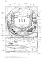
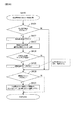
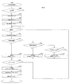
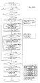
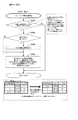
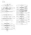
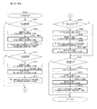
まず、図1及び図2を参照しながら、本実施形態に係るぱちんこ遊技機の前面側の基本構造を説明する。ぱちんこ遊技機は、大別すると遊技機枠Dと遊技盤Daとに分けられ、遊技機枠D及び遊技盤Daは、夫々複数のユニットを組み付けて形成されている。以下、遊技機枠D及び遊技盤Daを構成する各ユニットについて順に説明する。 First, the basic structure of the front side of the pachinko gaming machine according to the present embodiment will be described with reference to FIGS. 1 and 2. Pachinko gaming machines are roughly divided into a gaming machine frame D and a gaming board Da, and the gaming machine frame D and the gaming board Da are each formed by assembling a plurality of units. Hereinafter, each unit constituting the gaming machine frame D and the game board Da will be described in order.
はじめに、ぱちんこ遊技機の遊技機枠Dは、外枠ユニットD12、前枠ユニットD14、透明板ユニット(又はガラスユニットともいう)D16、扉ユニット(又はガラス扉、ともいう)D18、球皿ユニットD17(上球皿D20、下球皿D22及び発射ハンドルD44を総称してD17としている)を主体として構成される。 First, the gaming machine frame D of the pachinko gaming machine includes an outer frame unit D12, a front frame unit D14, a transparent plate unit (or glass unit) D16, a door unit (or glass door) D18, and a ball tray unit D17. (The upper ball dish D20, the lower ball dish D22, and the firing handle D44 are collectively referred to as D17).
外枠ユニットD12は、ぱちんこ遊技機を設置すべき位置に固定するための枠体であり、上下左右の枠杆(上枠杆D12d、下枠杆D12e、左枠杆D12a、右枠杆D12b)及び幕板D12cを、額縁状に適宜組み付けてユニット化されている。ここで、左枠杆D12aには、前枠ユニットD14を組み付けるための上下1組の前枠用ヒンジD12a‐1が固着され、右枠杆D12bには、前枠ユニットD14を施錠するための外枠側の施錠金具(不図示)が固着されている。また、本実施形態では、幕板D12cに遊技状態に応じた音声を出力可能なスピーカD24が配設されており、左右の枠杆(左枠杆D12a、右枠杆D12b)が金属により、上下の枠杆(上枠杆D12d、下枠杆D12e)が木材により、幕板D12cが樹脂により夫々形成されている。 The outer frame unit D12 is a frame for fixing the pachinko gaming machine to a position where it is to be installed, and the upper, lower, left, and right frame fences (upper frame collar D12d, lower frame collar D12e, left frame collar D12a, right frame collar D12b). The curtain plate D12c is assembled in a frame shape as a unit. Here, a pair of upper and lower front frame hinges D12a-1 for assembling the front frame unit D14 is fixed to the left frame rod D12a, and an outer frame for locking the front frame unit D14 is fixed to the right frame rod D12b. A frame side locking bracket (not shown) is fixed. In the present embodiment, the speaker D24 capable of outputting sound according to the gaming state is disposed on the curtain plate D12c, and the left and right frame rods (the left frame rod D12a and the right frame rod D12b) are vertically The frame frame (upper frame frame D12d, lower frame frame D12e) is made of wood, and the curtain plate D12c is made of resin.
前枠ユニットD14は、外形サイズが、外枠ユニットD12の開口部分に整合する枠体であり、外枠ユニットD12に設けられた前枠用ヒンジD12a‐1及び施錠金具(不図示)と、前枠ユニットD14の適宜位置に設けられた(これらに対応した)ヒンジ機構D14a‐1並びに施錠装置(不図示)により、外枠ユニットD12に対して横開き開閉可能、且つ施錠可能に取り付けられる。 The front frame unit D14 is a frame whose outer size is aligned with the opening of the outer frame unit D12. A hinge mechanism D14a-1 (corresponding to them) provided at an appropriate position of the frame unit D14 and a locking device (not shown) are attached to the outer frame unit D12 so that it can be opened and closed laterally and locked.
前枠ユニットD14には、遊技球を発射する発射機構、遊技盤Daを着脱可能に収容させるための遊技盤収容機構、賞球を付与するための賞球払出機構や、遊技済み球を誘導又は回収するための遊技済み球排出機構等が設けられている。本実施形態では、基体を成し遊技盤収容機構が形成されると共に発射機構の取り付けられた前枠本体D14aと、前枠本体D14aに着脱可能に取り付けられ、賞球払出機構、遊技済み球排出機構が形成された裏機構ユニットD14bと、から前枠ユニットD14が形成されている。また、前枠本体D14aの左側部には、後述する扉ユニットD18を組み付けるための上下1組のガラス枠用ヒンジD14a‐2が設けられており、前枠本体D14aの右側部に扉ユニットD18を施錠するためのガラス枠用施錠装置(不図示)が設けられている。更に前枠本体D14aの下部には、後述する球皿ユニットD17を組み付けるための球皿ユニット支持機構(球皿用ヒンジD14a‐3を含む)が設けられている。 The front frame unit D14 includes a launching mechanism for launching a game ball, a game board housing mechanism for detachably housing the game board Da, a prize ball payout mechanism for giving a prize ball, A game-completed ball discharge mechanism or the like for collection is provided. In the present embodiment, a base frame body D14a that forms a base and forms a game board accommodation mechanism and has a launch mechanism attached thereto, and is detachably attached to the front frame body D14a. A front frame unit D14 is formed from the back mechanism unit D14b in which the mechanism is formed. Further, a pair of upper and lower glass frame hinges D14a-2 for assembling a door unit D18, which will be described later, is provided on the left side of the front frame body D14a. A glass frame locking device (not shown) for locking is provided. Further, a ball tray unit support mechanism (including a ball tray hinge D14a-3) for assembling a ball tray unit D17, which will be described later, is provided below the front frame body D14a.
透明板ユニットD16は、複数枚(例えば2枚)のガラスやアクリル板などの透明板D16aを所定の間隔(20mm程度)をあけて平行に保持するためのものであり、コの字状の第一部材D16bに形成されたガラス保持部(不図示)にガラスを挿入した後に、挿入部分を遮蔽する第二部材D16cをはめ込み接着して一体化されて形成される。尚、透明板ユニットD16(特に、透明板D16a)は、後述する扉ユニットD18の開口面を介して、遊技盤Daの遊技領域D30を透視可能で且つ、当該開口面から異物が進入しない(当該開口面から遊技盤Da及び遊技領域D30へアクセス困難となる)ように取り付けられる。 The transparent plate unit D16 is for holding a plurality of (for example, two) transparent plates D16a such as glass and acrylic plates in parallel with a predetermined interval (about 20 mm). After glass is inserted into a glass holding portion (not shown) formed on the one member D16b, a second member D16c that shields the insertion portion is fitted and adhered to be integrated. The transparent plate unit D16 (particularly, the transparent plate D16a) can see through the game area D30 of the game board Da through an opening surface of the door unit D18 described later, and foreign matter does not enter from the opening surface (this It is difficult to access the game board Da and the game area D30 from the opening surface.
扉ユニット(ガラス扉)D18は、前枠ユニットD14に設けられたガラス枠用ヒンジD14a‐2及びガラス枠用施錠装置(不図示)と、扉ユニットD18の適宜位置に設けられた(これらに対応した)ヒンジ機構並びに施錠金具(不図示)により、前枠ユニットD14に対して横開き開閉可能、且つ施錠可能に取り付けられる。尚、扉ユニットD18は、外形サイズが、遊技盤Daの外形に略整合する大きさで構成されており、中央に透明板ユニットD16よりも小さい面積にて開口部D18aが設けられ、透明板ユニットD16を介して後述する遊技盤Da及び遊技領域D30が、視認可能となっている。 The door unit (glass door) D18 is provided at an appropriate position of the glass frame hinge D14a-2 and the glass frame locking device (not shown) provided in the front frame unit D14 and the door unit D18 (corresponding to these). It is attached to the front frame unit D14 so that it can be opened and closed laterally and locked by a hinge mechanism and a locking metal fitting (not shown). The door unit D18 is configured to have an outer size substantially matching the outer shape of the game board Da, and an opening D18a is provided in the center with an area smaller than that of the transparent plate unit D16. A game board Da and a game area D30, which will be described later, are visible through D16.
扉ユニットD18には、その背面側に、透明板ユニットD16を保持する透明板ユニット保持部D18b、開口部D18aの周囲に電飾効果や視覚的効果が得られるような装飾が施された装飾部D18c等も形成されている。尚、本実施形態では、扉ユニットD18の右上部に枠装飾ランプD18‐Lが配設されている。尚、枠装飾ランプD18‐Lの点灯によって後述する入球に係る情報を表示するよう構成してもよい。
扉ユニットD18の部品構成等についての詳細は後述する。
The door unit D18 has a transparent plate unit holding portion D18b for holding the transparent plate unit D16 on the back side thereof, and a decorative portion that is decorated around the opening D18a so as to obtain an electric decoration effect and a visual effect. D18c and the like are also formed. In the present embodiment, a frame decoration lamp D18-L is disposed at the upper right part of the door unit D18. In addition, you may comprise so that the information which concerns on the entering ball mentioned later may be displayed by lighting of the frame decoration lamp D18-L.
Details of the component configuration and the like of the door unit D18 will be described later.
球皿ユニットD17は、前枠ユニットD14に設けられた球皿ユニット支持機構(球皿用ヒンジD14a‐3を含む)と、球皿ユニットD17の適宜位置に設けられた係合部材(例えば、係合部材D17a‐1)とにより、前枠ユニットD14に対して着脱可能に取り付けられる。尚、球皿ユニットD17は、扉ユニットD18を開閉した状態でのみ前枠ユニットD14から着脱可能とすることで、当該遊技機専用の鍵を設けずとも、遊技に供されている状態では取り外しが困難な構造(例えば、扉ユニットD18の一部と球皿ユニットD17の一部がラップする構造)を採用している。 The ball tray unit D17 includes a ball tray unit support mechanism (including a ball tray hinge D14a-3) provided in the front frame unit D14 and an engagement member (for example, an engagement member) provided at an appropriate position of the ball tray unit D17. The joint member D17a-1) is detachably attached to the front frame unit D14. The ball tray unit D17 can be detached from the front frame unit D14 only when the door unit D18 is opened and closed, so that the ball tray unit D17 can be removed in a state where it is used for gaming without providing a dedicated key for the gaming machine. A difficult structure (for example, a structure in which a part of the door unit D18 and a part of the ball tray unit D17 wrap) is employed.
球皿ユニットD17は、外形サイズが、方形状に形成され、上部にて発射装置に遊技球を供給する上球皿D20、下部にて多数の賞球が払い出されたことにより、上球皿D20に過剰な遊技球が供給された場合に当該過剰分の遊技球を貯留可能な下球皿D22が形成され、下球皿D22の右側に、遊技者の操作により発射装置の発射強度(遊技球の打球位置)を調整する発射ハンドルD44が設けられている。また、球皿ユニットD17の一部表面(本例では、上球皿D20の上面)には、遊技者が演出時に操作するサブ入力ボタンSB、遊技球の貸し出し要求を行うための貸出操作部(不図示)が配設されている。また、上球皿D20と下球皿D22との間には、スピーカD24が設けられている。尚、球皿ユニットD17の部品構成等についての詳細は後述する。 The ball tray unit D17 has an outer size formed in a square shape, an upper ball tray D20 for supplying game balls to the launching device at the upper portion, and a large number of prize balls at the lower portion. When an excessive amount of game balls is supplied to D20, a lower ball tray D22 capable of storing the excess game balls is formed. On the right side of the lower ball plate D22, the launch intensity (game) A firing handle D44 for adjusting the ball hitting position) is provided. Further, on a part of the surface of the ball tray unit D17 (in this example, the upper surface of the upper ball tray D20), a sub input button SB operated by the player at the time of production, a lending operation unit for making a lending request for the game ball ( (Not shown) is provided. Further, a speaker D24 is provided between the upper ball tray D20 and the lower ball tray D22. Details of the component configuration of the ball tray unit D17 will be described later.
本実施形態における遊技機枠Dの概略構成は以上の通りであるが、前述したように、遊技機枠Dは複数のユニットから構成されており、より具体的には、外枠ユニットD12の前方に前枠ユニットD14(遊技盤Daを内包)、前枠ユニットD14の前方に透明板ユニットD16、扉ユニットD18及び球皿ユニットD17が、それぞれ着脱可能(又は開閉可能)に構成されている。このため、それぞれのユニットの整合部分には、開閉操作や着脱操作を容易にするための微少な間隙を有することとなる。よって、本実施形態においては、図示は省略するが、各ユニットの整合部分には、異物の混入を抑止するために、間隙が直線的にならないように整合部分にラビリンス構造(断面視で凹凸形状となるような構造)を採用していることが望ましい(但し、これには限定されない)。 Although the schematic configuration of the gaming machine frame D in the present embodiment is as described above, as described above, the gaming machine frame D is composed of a plurality of units, and more specifically, the front of the outer frame unit D12. The front frame unit D14 (including the game board Da), and the transparent plate unit D16, the door unit D18, and the ball tray unit D17 are configured to be detachable (or openable / closable) in front of the front frame unit D14. For this reason, the alignment part of each unit has a minute gap for facilitating the opening / closing operation and the attaching / detaching operation. Therefore, in this embodiment, although not shown in the drawings, the alignment portion of each unit has a labyrinth structure (uneven shape in a cross-sectional view) so that the gap does not become linear in order to prevent foreign matter from entering. It is desirable to employ a structure such that (but not limited to).
尚、本実施形態では、扉ユニットD18と球皿ユニットD17とが別体の構造を採用しているが、双方を一体構造を採用しても良い。また、本実施形態においては、遊技結果に応じて物理的な遊技媒体を払い出す構造を採用しているが、電子式な媒体管理を行うよう構成してもよい。その場合には、下球皿D22や賞球払出機構等は不要となり、遊技済み球を上球皿D20に戻して電子的な管理を行う遊技機形態(いわゆる封入循環形態)が採用され、球皿ユニットD17或いは扉ユニットD18等に電子媒体による精算・貸出用の操作部が配設されることになることを補足しておく。 In the present embodiment, the door unit D18 and the ball tray unit D17 adopt a separate structure, but both may adopt an integral structure. Further, in the present embodiment, a structure in which a physical game medium is paid out according to the game result is adopted. However, electronic medium management may be performed. In that case, the lower ball tray D22, the prize ball payout mechanism, etc. are not required, and a game machine form (so-called enclosed circulation form) in which a game-completed ball is returned to the upper ball dish D20 to perform electronic management is adopted. It will be supplemented that an operation unit for settlement / rental using an electronic medium is arranged in the dish unit D17 or the door unit D18.
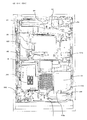
次に、遊技盤Daには、外レールD32と内レールD34とにより区画された遊技領域D30が形成されている。そして、当該遊技領域D30には、複数の遊技釘及び風車等の機構の他、第1主遊技始動口A10、第2主遊技始動口B10、補助遊技始動口H10、一般入賞口P10、第1大入賞口C10、第2大入賞口C20、第1主遊技図柄表示装置A20、第2主遊技図柄表示装置B20、演出表示装置SG、補助遊技図柄表示装置H20、センター飾りD38及びアウト口C80が設置されている。以下、各要素を順番に詳述する。 Next, a game area D30 partitioned by an outer rail D32 and an inner rail D34 is formed in the game board Da. The game area D30 includes a plurality of game nails and windmills, a first main game start port A10, a second main game start port B10, an auxiliary game start port H10, a general winning port P10, The big prize opening C10, the second big prize opening C20, the first main game symbol display device A20, the second main game symbol display device B20, the production display device SG, the auxiliary game symbol display device H20, the center decoration D38 and the out mouth C80. is set up. Hereinafter, each element will be described in detail.
まず、第1主遊技始動口A10は、第1主遊技に対応する始動入賞口として設置されている。具体的構成としては、第1主遊技始動口A10は、第1主遊技始動口入球検出装置A11sを備える。ここで、第1主遊技始動口入球検出装置A11sは、第1主遊技始動口A10への遊技球の入球を検出するセンサであり、入球時にその入球を示す第1主遊技始動口入球情報を生成する。 First, the first main game start opening A10 is installed as a start winning opening corresponding to the first main game. As a specific configuration, the first main game start opening A10 includes a first main game start opening entrance detection device A11s. Here, the first main game start entrance entrance detection device A11s is a sensor that detects the entrance of a game ball into the first main game start entrance A10, and the first main game start that indicates the entrance at the time of entrance. The entrance ball information is generated.
次に、第2主遊技始動口B10は、第2主遊技に対応する始動入賞口として設置されている。具体的構成としては、第2主遊技始動口B10は、第2主遊技始動口入球検出装置B11sと、第2主遊技始動口電動役物B11dと、を備える。ここで、第2主遊技始動口入球検出装置B11sは、第2主遊技始動口B10への遊技球の入球を検出するセンサであり、入球時にその入球を示す第2主遊技始動口入球情報を生成する。次に、第2主遊技始動口電動役物B11dは、第2主遊技始動口B10に遊技球が入球不能な閉鎖状態{平板状に形成された球受け部材(以下、球受け部材と称する)が遊技領域D30から引っ込んだ状態}と遊技球が入球可能な開放状態(球受け部材が遊技領域D30に突き出た状態)に可変する。ここで、本実施形態における第2主遊技始動口電動役物B11dは、球受け部が前後にスライドする形態の電動役物(いわゆる、ベロ電)を採用しており、開放状態にあるときには遊技領域D30に突出した球受け部材により遊技球を受け止めて、当該遊技球を第2入球検出装置B11s(遊技盤の内部に配置)に誘導するよう構成されている。また、本実施形態では、電動役物として、短時間での開放動作では遊技球の受け入れが困難となるように球受け部材が前後にスライドする形態の電動役物を採用したが、これには限定されず、遊技球が入球困難又は入球不能な閉鎖状態と、閉鎖状態よりも遊技球が入球容易な開放状態とを採り得る、所謂チューリップ型の電動役物を採用してもよい。 Next, the second main game start opening B10 is installed as a start winning opening corresponding to the second main game. Specifically, the second main game start port B10 includes a second main game start port entrance detection device B11s and a second main game start port electric accessory B11d. Here, the second main game start entrance entrance detection device B11s is a sensor that detects the entrance of a game ball to the second main game start entrance B10, and the second main game start that indicates the entrance at the time of entrance. The entrance ball information is generated. Next, the second main game start opening electric accessory B11d is in a closed state where a game ball cannot enter the second main game start opening B10 {a ball receiving member formed in a flat plate shape (hereinafter referred to as a ball receiving member). ) Withdrawn from the game area D30} and an open state in which a game ball can enter (a state in which the ball receiving member protrudes into the game area D30). Here, as the second main game start opening electric accessory B11d in the present embodiment, an electric accessory (so-called “velo electric”) in which the ball receiving portion slides back and forth is adopted, and when it is in the open state, the game The game ball is received by the ball receiving member protruding into the region D30, and the game ball is guided to the second ball detection device B11s (arranged inside the game board). Further, in the present embodiment, as the electric combination, an electric combination in which the ball receiving member slides back and forth is adopted so that it is difficult to receive the game ball in the opening operation in a short time. There is no limitation, and so-called tulip-type electric accessories that can take a closed state in which a game ball is difficult or impossible to enter and an open state in which the game ball is easier to enter than in the closed state may be adopted. .
ここで、本実施形態においては、第1主遊技始動口A10と第2主遊技始動口B10とが離隔して設けられており、遊技領域D30の左側(遊技領域中央を基準)を流下する遊技球が、第1主遊技始動口A10に誘導され易い一方、第2主遊技始動口B10に誘導され難いよう構成されている。他方、遊技領域D30の右側(遊技領域中央を基準)を流下する遊技球は、第1主遊技始動口A10に誘導され難い一方、第2主遊技始動口B10に誘導され易いよう構成されている。尚、「誘導され易い」及び「誘導され難い」は、例えば、遊技球を右側及び左側にそれぞれ10000球発射した際の、入球数の大小で決定するものとする。 Here, in the present embodiment, the first main game start port A10 and the second main game start port B10 are provided apart from each other, and flow down the left side of the game area D30 (based on the center of the game area). The ball is configured to be easily guided to the first main game start opening A10, but difficult to be guided to the second main game start opening B10. On the other hand, the game ball flowing down the right side of the game area D30 (referenced to the center of the game area) is not easily guided to the first main game start port A10, but is easily guided to the second main game start port B10. . It should be noted that “easy to be guided” and “not easily guided” are determined, for example, by the magnitude of the number of entered balls when 10,000 balls are launched to the right and left, respectively.
尚、本実施形態では、第2主遊技始動口B10側に電動役物を設けるよう構成したが、これには限定されず、第1主遊技始動口A10側に電動役物を設けるよう構成してもよい。更には、本実施形態では、第1主遊技始動口A10と第2主遊技始動口B10とが離隔して配置されているが、これにも限定されず、第1主遊技始動口A10と第2主遊技始動口B10とを重ねるように配置してもよく、その場合には、第1主遊技始動口A10の存在により、第2主遊技始動口B10の上部が塞がれているよう構成してもよい。 In the present embodiment, the electric combination is provided on the second main game start opening B10 side. However, the present invention is not limited to this, and the electric combination is provided on the first main game start opening A10 side. May be. Furthermore, in the present embodiment, the first main game start port A10 and the second main game start port B10 are spaced apart from each other, but the present invention is not limited to this, and the first main game start port A10 and the first main game start port A10 The two main game start ports B10 may be arranged so as to overlap with each other. In that case, the upper portion of the second main game start port B10 is blocked by the presence of the first main game start port A10. May be.
次に、補助遊技始動口H10は、補助遊技始動口入球検出装置H11sを備える。ここで、補助遊技始動口入球検出装置H11sは、補助遊技始動口H10への遊技球の入球を検出するセンサであり、入球時にその入球を示す補助遊技始動口入球情報を生成する。尚、補助遊技始動口H10への遊技球の入球は、第2主遊技始動口B10の第2主遊技始動口電動役物B11dを拡開させるための抽選の契機となる。 Next, the auxiliary game start port H10 includes an auxiliary game start port entrance detection device H11s. Here, the auxiliary game start port entrance detection device H11s is a sensor that detects the entrance of a game ball to the auxiliary game start port H10, and generates auxiliary game start port entrance information indicating the entrance at the time of entrance. To do. Note that the entry of the game ball into the auxiliary game start port H10 triggers a lottery to expand the second main game start port electric accessory B11d of the second main game start port B10.
次に、一般入賞口P10は、一般入賞口入球検出装置P11sを備える。一般入賞口入球検出装置P11sは、一般入賞口P10への遊技球の入球を検出するセンサであり、入球時にその入球を示す一般入賞口入球情報を生成する。尚、一般入賞口P10への遊技球の入球によって、所定数(例えば、10球)の遊技球が賞球として払い出されることとなる。尚、一般入賞口P10は複数設けられており、遊技領域D30の左側(遊技領域中央を基準)を流下する遊技球と、遊技領域D30の右側(遊技領域中央を基準)を流下する遊技球と、のいずれもが一般入賞口P10に入球容易となっている。尚、一般入賞口P10の数は変更しても問題なく、遊技領域D30の右側(遊技領域中央を基準)を流下する遊技球のみが入球容易としても、遊技領域D30の左側(遊技領域中央を基準)を流下する遊技球のみが入球容易としてもよい。 Next, the general winning opening P10 includes a general winning opening entering device P11s. The general winning opening entrance detection device P11s is a sensor that detects the entrance of a game ball into the general winning opening P10, and generates general winning opening entrance information indicating the entering at the time of entering. Note that a predetermined number (for example, 10 balls) of game balls are paid out as prize balls by entering the game balls into the general winning opening P10. A plurality of general winning openings P10 are provided, and a game ball that flows down the left side of the game area D30 (based on the center of the game area) and a game ball that flows down the right side of the game area D30 (based on the center of the game area) Are easy to enter the general winning opening P10. It should be noted that there is no problem even if the number of the general winning opening P10 is changed. Only the game balls that flow down the standard) may be easy to enter.
ここで、本実施形態においては、遊技領域D30の左側(遊技領域中央を基準)を流下する遊技球が、補助遊技始動口H10に誘導され難い一方、遊技領域D30の右側(遊技領域中央を基準)を流下する遊技球は、補助遊技始動口H10に誘導され易いよう構成されている{但し、これには限定されず、遊技領域D30の左側(遊技領域中央を基準)を流下する遊技球をも、補助遊技始動口H10に誘導され易いよう構成してもよい}。 Here, in the present embodiment, the game ball flowing down the left side of the game area D30 (reference to the center of the game area) is difficult to be guided to the auxiliary game start port H10, while the right side of the game area D30 (reference to the center of the game area). ) Is configured to be easily guided to the auxiliary game start opening H10 (but not limited to this, the game ball flowing down the left side of the game area D30 (based on the center of the game area) May be configured to be easily guided to the auxiliary game start opening H10}.
次に、アウト口C80の上方(特に、遊技領域D30の右側)には、第1大入賞口C10と第2大入賞口C20とが設けられており、遊技領域D30の右側(遊技領域中央を基準)を流下する遊技球は、アウト口C80に到達する前に、第1大入賞口C10及び第2大入賞口C20が配置されている領域を通過し易いよう構成されている。 Next, a first big prize opening C10 and a second big prize opening C20 are provided above the out mouth C80 (in particular, the right side of the game area D30), and the right side of the game area D30 (in the middle of the game area). The game balls flowing down the standard) are configured to easily pass through the area where the first grand prize winning opening C10 and the second big winning prize opening C20 are arranged before reaching the out opening C80.
次に、第1大入賞口C10は、第1主遊技図柄(特別図柄)又は第2主遊技図柄(特別図柄)が大当り図柄停止した場合に開状態となる、横長方形状を成しアウト口C80の上方(特に、遊技領域D30の右側)に位置した、主遊技に対応した入賞口である。具体的構成としては、第1大入賞口C10は、遊技球の入球を検出するための第1大入賞口入賞検出装置C11sと、第1大入賞口電動役物C11d(及び第1大入賞口ソレノイドC13)と、を備える。ここで、第1大入賞口入賞検出装置C11sは、第1大入賞口C10への遊技球の入球を検出するセンサであり、入球時にその入球を示す第1大入賞口入球情報を生成する。第1大入賞口電動役物C11dは、第1大入賞口C10に遊技球が入賞不能又は入賞困難な通常状態と遊技球が入賞し易い開放状態に第1大入賞口C10を可変させる(第1大入賞口ソレノイドC13を励磁して可変させる)。尚、本実施形態では、大入賞口の態様を、横長方形状を成し遊技球が入賞不能又は入賞困難な通常状態と遊技球が入賞し易い開放状態とに可変させる態様としているが、これには限定されない。その場合には、例えば、大入賞口に設けられた棒状部材が遊技者側に突き出した状態である進出状態と遊技者側に対して引っ込んだ状態である退避状態とを採り得る態様(いわゆる、スライド式アタッカーであり、遊技領域D30から突出し遊技領域D30を流下する遊技球を受入れ可能な箱状の部材を大入賞口自体が有しており、進出状態にある場合には当該箱状の部材への遊技球の受け入れが阻害されることで大入賞口が閉状態となり、退避状態にある場合には当該箱状の部材への遊技球の受け入れが許容されることで大入賞口が開状態となる構成)としてもよく、大入賞口への入球数を所定数(例えば、10個)とすることを担保したい場合において好適である。 Next, the first grand prize winning opening C10 has a horizontal rectangular shape that is opened when the first main game symbol (special symbol) or the second main game symbol (special symbol) is stopped by the big hit symbol, and is an out port. It is a winning opening corresponding to the main game, located above C80 (in particular, the right side of the game area D30). Specifically, the first grand prize opening C10 includes a first grand prize opening prize detection device C11s for detecting the entry of a game ball, and a first grand prize opening electric accessory C11d (and a first grand prize prize). Mouth solenoid C13). Here, the first grand prize opening winning detection device C11s is a sensor that detects the entry of a game ball into the first big prize opening C10. Is generated. The first grand prize opening electric accessory C11d changes the first big prize opening C10 to the first big prize opening C10 in a normal state in which a game ball cannot be won or difficult to win and an open state in which the game ball is easy to win (first). 1) The first prize winning solenoid C13 is excited and varied). In the present embodiment, the mode of the big winning opening is a mode in which a horizontal rectangular shape is formed and the game ball is variable between a normal state where the game ball cannot be won or difficult to win and an open state where the game ball is easy to win. It is not limited to. In that case, for example, an aspect (so-called, a state in which a bar-like member provided in the big prize opening is in a state of protruding to the player side and a retracted state in which it is retracted with respect to the player side) The slide-type attacker has a box-shaped member that can receive a game ball that protrudes from the game area D30 and flows down the game area D30. The prize-winning mouth is closed due to obstruction of the acceptance of the game ball into the box, and when it is in the retracted state, the prize-winning mouth is open by allowing the reception of the game ball into the box-shaped member This is suitable for the case where it is desired to ensure that the number of balls entered into the grand prize opening is a predetermined number (for example, 10).
次に、第2大入賞口C20は、第1主遊技図柄(特別図柄)又は第2主遊技図柄(特別図柄)が大当り図柄で停止した場合に開状態となる、横長方形状を成しアウト口C80の上方(特に、遊技領域D30の右側)に位置した、主遊技に対応した入賞口である。具体的構成としては、第2大入賞口C20は、遊技球の入球を検出するための第2大入賞口入賞検出装置C21sと、第2大入賞口電動役物C21d(及び第2大入賞口ソレノイドC23)と、を備える。ここで、第2大入賞口入賞検出装置C21sは、第2大入賞口C20への遊技球の入球を検出するセンサであり、入球時にその入球を示す第2大入賞口入球情報を生成する。そして、第2大入賞口C20内に入球した遊技球は、第2大入賞口入賞検出装置C21sによって検出されるよう構成されている。次に、第2大入賞口電動役物C21dは、第2大入賞口C20に遊技球が入賞不能又は入賞困難な通常状態と遊技球が入賞し易い開放状態とに第2大入賞口C20を可変させる(第2大入賞口ソレノイドC23を励磁して可変させる)。尚、本実施形態では、大入賞口の態様を、横長方形状を成し遊技球が入賞不能又は入賞困難な通常状態と遊技球が入賞し易い開放状態とに可変させる態様としているが、これには限定されない。その場合には、例えば、大入賞口に設けられた棒状部材が遊技者側に突き出した状態である進出状態と遊技者側に対して引っ込んだ状態である退避状態とを採り得る態様(いわゆる、スライド式アタッカーであり、遊技領域D30から突出し遊技領域D30を流下する遊技球を受入れ可能な箱状の部材を大入賞口自体が有しており、進出状態にある場合には当該箱状の部材への遊技球の受け入れが阻害されることで大入賞口が閉状態となり、退避状態にある場合には当該箱状の部材への遊技球の受け入れが許容されることで大入賞口が開状態となる構成)としてもよく、大入賞口への入球数を所定数(例えば、10個)とすることを担保したい場合において好適である。 Next, the second grand prize opening C20 is formed in a horizontal rectangular shape that is opened when the first main game symbol (special symbol) or the second main game symbol (special symbol) stops at the big hit symbol. The winning opening corresponding to the main game is located above the opening C80 (in particular, the right side of the game area D30). Specifically, the second grand prize opening C20 includes a second grand prize opening prize detection device C21s for detecting the entry of a game ball, and a second grand prize opening electric accessory C21d (and a second grand prize prize). Mouth solenoid C23). Here, the second grand prize opening prize detection device C21s is a sensor that detects the entry of a game ball into the second big prize opening C20, and the second big prize opening entry information that indicates the entry at the time of entry. Is generated. The game balls that have entered the second grand prize opening C20 are configured to be detected by the second big prize opening prize detection device C21s. Next, the second big prize opening electric accessory C21d has the second big prize opening C20 in the second big prize opening C20 in a normal state where a game ball cannot be won or difficult to win and an open state where the game ball is easy to win. Variable (exciting and changing the second big prize opening solenoid C23). In the present embodiment, the mode of the big winning opening is a mode in which a horizontal rectangular shape is formed and the game ball is variable between a normal state where the game ball cannot be won or difficult to win and an open state where the game ball is easy to win. It is not limited to. In that case, for example, an aspect (so-called, a state in which a bar-like member provided in the big prize opening is in a state of protruding to the player side and a retracted state in which it is retracted with respect to the player side) The slide-type attacker has a box-shaped member that can receive a game ball that protrudes from the game area D30 and flows down the game area D30. The prize-winning mouth is closed due to obstruction of the acceptance of the game ball into the box, and when it is in the retracted state, the prize-winning mouth is open by allowing the reception of the game ball into the box-shaped member This is suitable for the case where it is desired to ensure that the number of balls entered into the grand prize opening is a predetermined number (for example, 10).
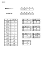
次に、第1主遊技図柄表示装置A20(第2主遊技図柄表示装置B20)は、第1主遊技(第2主遊技)に対応する第1主遊技図柄(第2主遊技図柄)に関連した表示等を実行する装置である。具体的構成としては、第1主遊技図柄表示装置A20(第2主遊技図柄表示装置B20)は、第1主遊技図柄表示部A21g(第2主遊技図柄表示部B21g)と、第1主遊技図柄保留表示部A21h(第2主遊技図柄保留表示部B21h)とを備える。ここで、第1主遊技図柄保留表示部A21h(第2主遊技図柄保留表示部B21h)は、4個のランプから構成され、当該ランプの点灯個数が、第1主遊技(第2主遊技)に係る乱数の保留数(実行されていない主遊技図柄の変動数)に相当する。尚、第1主遊技図柄表示部A21g(第2主遊技図柄表示部B21g)は、例えば7セグメントLEDで構成され、第1主遊技図柄(第2主遊技図柄)は、「0」〜「9」の10種類の数字及びハズレの「‐」で表示される{但し、これには限定されず、いずれの主遊技図柄が表示されたのかを遊技者が認識困難となるよう、7セグメントLEDを用いて記号等によって表示することが好適である。また、保留数表示においても、4個のランプから構成されていることには限定されず、最大4個分の保留数を表示可能に構成(例えば、1個のランプから構成されており、保留数1:点灯、保留数2:低速点滅、保留数3:中速点滅、保留数4:高速点滅、するよう構成)されていればよい}。 Next, the first main game symbol display device A20 (second main game symbol display device B20) is related to the first main game symbol (second main game symbol) corresponding to the first main game (second main game symbol). It is a device that executes the display and the like. Specifically, the first main game symbol display device A20 (second main game symbol display device B20) includes a first main game symbol display unit A21g (second main game symbol display unit B21g) and a first main game game. And a symbol hold display portion A21h (second main game symbol hold display portion B21h). Here, the first main game symbol hold display portion A21h (second main game symbol hold display portion B21h) is composed of four lamps, and the number of lighting of the lamps is the first main game (second main game). This corresponds to the number of random numbers held (the number of main game symbols that have not been executed). The first main game symbol display unit A21g (second main game symbol display unit B21g) is configured with, for example, a 7-segment LED, and the first main game symbol (second main game symbol) is “0” to “9”. ”Is displayed with 10 types of numbers and“ − ”of lose. {However, it is not limited to this. A 7-segment LED is set so that it is difficult for the player to recognize which main game symbol is displayed. It is preferable to use and display by a symbol or the like. In addition, the hold number display is not limited to being composed of four lamps, but can be configured to display a maximum of four hold numbers (for example, composed of one lamp, (Equation 1: lighting, hold number 2: slow blink, hold number 3: medium blink, hold number 4: fast blink)).
尚、第1主遊技図柄(第2主遊技図柄)は必ずしも演出的な役割を持つ必要が無いため、本実施形態では、第1主遊技図柄表示装置A20(第2主遊技図柄表示装置B20)の大きさは、目立たない程度に設定されている。しかしながら、第1主遊技図柄(第2主遊技図柄)自体に演出的な役割を持たせて第1装飾図柄(第2装飾図柄)を表示させないような手法を採用する場合には、後述する演出表示装置SGのような液晶ディスプレーに、第1主遊技図柄(第2主遊技図柄)を表示させるように構成してもよい。 Since the first main game symbol (second main game symbol) does not necessarily have an effect role, in this embodiment, the first main game symbol display device A20 (second main game symbol display device B20). The size of is set to be inconspicuous. However, in the case of adopting a technique that does not display the first decorative symbol (second decorative symbol) by giving the first main gaming symbol (second main gaming symbol) itself an effect role, an effect described later You may comprise so that a 1st main game symbol (2nd main game symbol) may be displayed on a liquid crystal display like display apparatus SG.
次に、演出表示装置SGは、第1主遊技図柄・第2主遊技図柄と連動して変動・停止する装飾図柄を含む演出画像の表示等を実行する装置である。ここで、具体的構成としては、演出表示装置SGは、装飾図柄の変動表示等を含めて演出が実行される表示領域SG10を備える。ここで、表示領域SG10は、主遊技保留情報を表示する第1保留表示部SG12(及び第2保留表示部SG13)と、例えば、スロットマシンのゲームを模した複数列の装飾図柄変動の動画像を表示する装飾図柄表示領域SG11と、を有している。尚、演出表示装置SGは、本実施形態では液晶ディスプレーで構成されているが、機械式のドラムやLED等の他の表示手段で構成されていてもよい。次に、第1保留表示部SG12(及び第2保留表示部SG13)は、4個のランプから構成され、当該ランプは、主遊技図柄の保留ランプと連動している。 Next, the effect display device SG is a device that displays an effect image including a decorative symbol that fluctuates and stops in conjunction with the first main game symbol and the second main game symbol. Here, as a specific configuration, the effect display device SG includes a display area SG10 where an effect is executed including a variable display of decorative symbols. Here, the display area SG10 includes a first hold display section SG12 (and a second hold display section SG13) that displays main game hold information, and a moving image of a plurality of rows of decorative symbols imitating, for example, a slot machine game. And a decorative symbol display area SG11 for displaying. The effect display device SG is configured with a liquid crystal display in the present embodiment, but may be configured with other display means such as a mechanical drum or LED. Next, the first hold display section SG12 (and the second hold display section SG13) is composed of four lamps, and the lamps are linked with the hold lamp of the main game symbol.
次に、補助遊技図柄表示装置H20は、補助遊技図柄に関する表示等を実行する装置である。具体的構成としては、補助遊技図柄表示装置H20は、補助遊技図柄表示部H21gと、補助遊技図柄保留表示部H21hとを備える。ここで、補助遊技図柄保留表示部H21hは、4個のランプから構成され、当該ランプの点灯個数が、補助遊技図柄変動の保留数(実行されていない補助遊技図柄変動の数)に相当する。 Next, the auxiliary game symbol display device H20 is a device that executes display related to the auxiliary game symbols. As a specific configuration, the auxiliary game symbol display device H20 includes an auxiliary game symbol display unit H21g and an auxiliary game symbol hold display unit H21h. Here, the auxiliary game symbol hold display portion H21h is composed of four lamps, and the number of lighting of the lamps corresponds to the number of auxiliary game symbol changes held (the number of auxiliary game symbol changes not being executed).
次に、センター飾りD38は、演出表示装置SGの周囲に設置され、遊技球の流路、演出表示装置SGの保護、装飾等の機能を有する。また、遊技効果ランプD26は、遊技領域D30又は遊技領域D30以外の領域に設けられ、点滅等することで演出の役割を果たす。尚、遊技効果ランプD26の点灯によって後述する入球に係る情報を表示するよう構成してもよい。 Next, the center decoration D38 is installed around the effect display device SG, and has functions such as a flow path of the game ball, protection of the effect display device SG, and decoration. In addition, the game effect lamp D26 is provided in a game area D30 or an area other than the game area D30, and plays a role of effect by blinking or the like. In addition, you may comprise so that the information which concerns on the below-mentioned entry may be displayed by lighting of the game effect lamp | ramp D26.
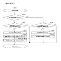
次に、入球状態表示装置J10は、第1主遊技始動口A10、第2主遊技始動口B10及び一般入賞口P10への遊技球の入球状況{非確率変動遊技状態且つ非時間短縮遊技状態(主遊技確変フラグオフ且つ主遊技時短フラグオフ)での入球状況を表示してもよい}が正常であるか異常であるかの情報を表示する表示装置である。尚、入球状況が異常であるとは、一般入賞口P10に向けて遊技球が流下するように誘導する遊技釘が遊技機の出荷時とは異なる方向に曲がっており、一般入賞口P10へ向けて遊技球を発射し続けても入り難い状況である、等を異常としている。尚、本実施形態においては、第1主遊技始動口A10又は第2主遊技始動口B10へ入球した遊技球と一般入賞口P10へ入球した遊技球との比率が想定した範囲外となっている場合に異常であると判定するよう構成されている。また、詳細は後述することとなるが、入球状態表示装置J10にて表示し得る要素は、上述したものには限定されず、ベース値(所定の入賞口による賞球払出数を遊技球の総発射球数で除算した値を100倍した値であり、詳細は後述する)等、様々な要素を表示可能に構成されている。 Next, the entry state display device J10 has the state of the entry of the game ball into the first main game start port A10, the second main game start port B10, and the general winning port P10 {non-probability variation game state and non-time-reduced game This is a display device that displays information on whether the state of entry in the state (the main game probability change flag is off and the main game short time flag is off) is normal or abnormal. In addition, if the game situation is abnormal, the game nail that guides the game ball to flow down toward the general prize opening P10 is bent in a direction different from that at the time of shipment of the gaming machine. Even if it keeps firing a game ball towards it, it is difficult to enter, etc. In the present embodiment, the ratio of the game ball that has entered the first main game start port A10 or the second main game start port B10 and the game ball that has entered the general winning port P10 is outside the assumed range. It is comprised so that it may determine with it being abnormal. Further, although details will be described later, the elements that can be displayed on the ball entry state display device J10 are not limited to those described above. Various values such as a value obtained by multiplying the value obtained by dividing the total number of shot balls by 100 are described in detail later).
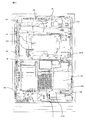
次に、図3を参照しながら、ぱちんこ遊技機の背面側における基本構造を説明する。ぱちんこ遊技機は、ぱちんこ遊技機の全体動作を制御し、特に第1主遊技始動口A10(第2主遊技始動口B10)へ入球したときの抽選等、遊技動作全般の制御(即ち、遊技者の利益と直接関係する制御)を行う主制御基板Mと、遊技内容に興趣性を付与する演出表示装置SG上での各種演出に係る表示制御等を行う演出制御手段(サブメイン制御部)SMと、主に演出表示を実行するサブサブ制御部SSと、所定のエラー発生時に点灯してエラー発生を報知するエラーランプSS3と、賞球タンクKT、賞球レールKR及び各入賞口への入賞に応じて賞球タンクKTから供給される遊技球を上球皿D20へ払い出す賞球払出ユニットKE10等を備える賞球払出装置(セット基盤)KEと、賞球払出ユニットKE10による払出動作を制御する賞球払出制御基板KHと、払出に係るエラーの発生状況を表示(例えば、7セグ表示)するエラー表示器KH3と、所定のエラーを解除するためのエラー解除スイッチKH3aと、上球皿D20の遊技球(貯留球)を遊技領域D30へ1球ずつ発射する発射装置D42と、発射装置D42の発射動作を制御する発射制御基板D40と、ぱちんこ遊技機の各部へ電力を供給する電源供給ユニットEと、ぱちんこ遊技機の電源をオン・オフするスイッチである電源スイッチEa等が、前枠ユニットD14裏面(遊技側と反対側)に設けられている。 Next, the basic structure on the back side of the pachinko gaming machine will be described with reference to FIG. The pachinko gaming machine controls the overall operation of the pachinko gaming machine, and in particular controls overall game operations such as lottery when entering the first main game starting port A10 (second main game starting port B10) (ie, game Main control board M that performs control directly related to the profits of the player, and effect control means (sub-main control unit) that performs display control and the like related to various effects on the effect display device SG that adds interest to the game content SM, a sub-sub control unit SS that mainly performs effect display, an error lamp SS3 that lights up when a predetermined error occurs and notifies the occurrence of the error, a prize ball tank KT, a prize ball rail KR, and a prize to each prize opening In accordance with the prize ball tank KT, the prize ball payout device (set base) KE including the prize ball payout unit KE10 for paying out the game balls to the upper ball tray D20 and the payout operation by the prize ball payout unit KE10 are controlled. A prize ball payout control board KH, an error indicator KH3 for displaying an error occurrence state (for example, 7-segment display), an error release switch KH3a for releasing a predetermined error, and an upper ball tray D20 Launching device D42 that launches each game ball (reserved ball) into the game area D30, a launch control board D40 that controls the launching operation of the launching device D42, and a power supply unit that supplies power to each part of the pachinko gaming machine E and a power switch Ea, which is a switch for turning on / off the power of the pachinko gaming machine, are provided on the rear surface of the front frame unit D14 (opposite the game side).
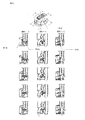
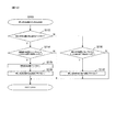
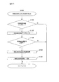
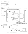
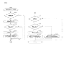
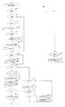
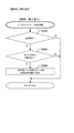
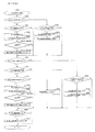
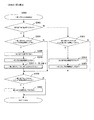
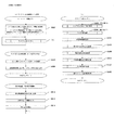
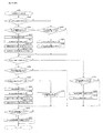
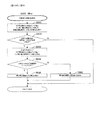
次に、図4及び図5を参照しながら、本実施形態に係るぱちんこ遊技機の賞球払出ユニットKE10の構造と遊技球の払出を行う動作原理を説明することとする。まず、図4上段に示されるように、賞球払出ユニットKE10は、払出の際に駆動される払出モータ(ステッピングモータ)KE10mを有している。そして、図4下段に示されるように、賞球払出ユニットKE10は、ステッピングモータKE10mと連結したスプロケットKE10pを有している。このような構造の賞球払出ユニットKE10は、下記の原理に従い動作する。まず、遊技領域内の入賞口に遊技球が入球すると、入賞信号が主制御基板Mに送られ主制御基板Mは払出個数を決定し、賞球払出制御基板KHへ賞球の信号を送信する。或いは、カードユニットR等の遊技球貸出装置から賞球払出制御基板KHへ球貸しの要求がなされる。これを受けて賞球払出制御基板KHは賞球払出ユニットKE10を作動させ、賞球払出ユニットKE10内のステッピングモータKE10mが遊技球の払出を実行する。図5に示されるように、ステッピングモータKE10mが回転することにより、スプロケットKE10p(第1スプロケットKE10p1、第2スプロケットKE10p2及び回転確認用部材KE10p3が一体となっている部材)が回転し、遊技球が1球ずつ払い出される。また、払い出された遊技球は、賞球払出ユニットKE10の下流に連続して設けられた払出カウントセンサKE10sにより検知される。尚、断面C‐Cについては、図示されるように、遊技球の流路に沿った(流路が見えやすい)断面を図示していることを補足しておく。 Next, with reference to FIGS. 4 and 5, the structure of the prize ball payout unit KE10 of the pachinko gaming machine according to the present embodiment and the operating principle for paying out the game balls will be described. First, as shown in the upper part of FIG. 4, the winning ball payout unit KE10 has a payout motor (stepping motor) KE10m that is driven at the time of payout. As shown in the lower part of FIG. 4, the winning ball payout unit KE10 includes a sprocket KE10p connected to a stepping motor KE10m. The prize ball payout unit KE10 having such a structure operates according to the following principle. First, when a game ball enters the winning opening in the game area, a winning signal is sent to the main control board M, the main control board M determines the number of payouts, and sends a signal of the winning ball to the winning ball payout control board KH To do. Alternatively, a ball lending request is made from the game ball lending device such as the card unit R to the prize ball payout control board KH. In response to this, the prize ball payout control board KH operates the prize ball payout unit KE10, and the stepping motor KE10m in the prize ball payout unit KE10 executes the payout of the game ball. As shown in FIG. 5, when the stepping motor KE10m rotates, the sprocket KE10p (the member in which the first sprocket KE10p1, the second sprocket KE10p2 and the rotation confirmation member KE10p3 are integrated) rotates, and the game ball is rotated. One ball is paid out. Also, the paid-out game balls are detected by a payout count sensor KE10s provided continuously downstream of the prize ball payout unit KE10. As for the cross section CC, it is supplemented that a cross section along the flow path of the game ball (the flow path is easily visible) is illustrated as shown.
また、図4下段は、ロータ位置確認センサ(払出モータ位置センサ)KE10msと回転体(スプロケット)KE10pとを模式的に示した図である(一例)。ロータ位置確認センサKE10msは、一対の測定部を有しており、測定部間の物体を光の投受光により検出するフォトセンサである。ここで、一対の測定部は、光を投光する投光部と、投光部からの光を受光する受光部であり、回転確認用部材KE10p3を挟んで配置されている。ここで、回転確認用部材KE10p3は、円周に沿って6個の凹部が形成されており、回転確認用部材KE10p3がこれら投光部と受光部との間に介在しているときにはオフとなり、回転確認用部材KE10p3がこれら投光部と受光部との間に介在していないときにはオン(図4下段の状態)となる。 The lower part of FIG. 4 is a diagram schematically showing a rotor position confirmation sensor (dispensing motor position sensor) KE10 ms and a rotating body (sprocket) KE10p (an example). The rotor position confirmation sensor KE10ms is a photosensor that has a pair of measurement units and detects an object between the measurement units by projecting and receiving light. Here, the pair of measuring units are a light projecting unit that projects light and a light receiving unit that receives light from the light projecting unit, and is arranged with the rotation confirmation member KE10p3 interposed therebetween. Here, the rotation confirmation member KE10p3 has six concave portions formed along the circumference, and is turned off when the rotation confirmation member KE10p3 is interposed between the light projecting unit and the light receiving unit. When the rotation confirmation member KE10p3 is not interposed between the light projecting part and the light receiving part, it is turned on (the lower state in FIG. 4).
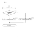
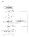
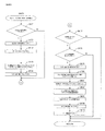
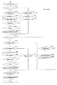
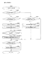
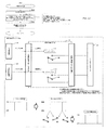
次に、図6のブロック図を参照しながら、本実施形態に係るぱちんこ遊技機の電気的な概略構成を説明する。はじめに、本実施形態に係るぱちんこ遊技機は、前述したように、遊技の進行を制御する主制御基板Mと、主制御基板Mからの情報(信号、コマンド等)に基づいて遊技球の払出を制御する賞球払出制御基板KHと、主制御基板Mからの情報(信号、コマンド等)に基づいて装飾図柄の変動・停止等の演出表示装置SG上での各種演出、スピーカD24からの音響、遊技効果ランプD26の点灯、エラー報知等の実行を制御する副制御基板S(本例では、サブメイン制御部SMとサブサブ制御部SSとが一つの基板上に配置されている)と、これらの制御基板を含む遊技機全体に電源を供給する電源供給ユニットEと、を主体として構成されている。ここで、副制御基板Sは、装飾図柄の変動・停止等の演出表示装置SG上での各種演出、スピーカD24からの音響、遊技効果ランプD26の点灯、エラー報知を制御するサブメイン制御部SMと、演出表示装置SG上での装飾図柄の変動表示・停止表示及び保留表示や予告表示等の表示処理を実行するサブサブ制御部SSの2つの制御部とを備えている。尚、主制御基板M、賞球払出制御基板KH、サブメイン制御部SM及びサブサブ制御部SSには、様々な演算処理を行うCPU、CPUの演算処理を規定したプログラムを予め記憶するROM、CPUが取り扱うデータ(遊技中に発生する各種データやROMから読み出されたコンピュータプログラム等)を一時的に記憶するRAM、電断時に情報を保持するためのバックアップ領域(及びバックアップ用電源)が搭載されている。 Next, an electrical schematic configuration of the pachinko gaming machine according to the present embodiment will be described with reference to the block diagram of FIG. First, the pachinko gaming machine according to the present embodiment, as described above, pays out a game ball based on the main control board M that controls the progress of the game and information (signals, commands, etc.) from the main control board M. Based on information (signals, commands, etc.) from the prize ball payout control board KH to be controlled, various effects on the effect display device SG, such as variation / stop of decorative symbols, sound from the speaker D24, A sub-control board S (in this example, the sub-main control unit SM and the sub-sub-control unit SS are arranged on one board) for controlling execution of the lighting of the game effect lamp D26, error notification, etc., and these A power supply unit E that supplies power to the entire gaming machine including the control board is mainly configured. Here, the sub-control board S is a sub-main control unit SM that controls various effects on the effect display device SG such as variation / stop of decorative symbols, sound from the speaker D24, lighting of the game effect lamp D26, and error notification. And two control units of a sub-sub control unit SS that performs display processing such as a decorative symbol change display / stop display and a hold display or a notice display on the effect display device SG. The main control board M, the winning ball payout control board KH, the sub-main control unit SM, and the sub-sub control unit SS are a CPU that performs various arithmetic processes, and a ROM that stores programs that prescribe the arithmetic processes of the CPU and CPU RAM that temporarily stores data (various data generated during games and computer programs read from ROM, etc.) handled by, and a backup area (and power supply for backup) for holding information when power is interrupted ing.
以下、各基板の概略構成及び各基板・装置間の電気的な接続態様について概説する。まず、主制御基板Mは、入賞口センサNs{前述した第1主遊技始動口入球検出装置A11s、第2主遊技始動口入球検出装置B11s、補助遊技始動口入球検出装置H11s、第1大入賞口入賞検出装置C11s、第2大入賞口入賞検出装置C21s、一般入賞口入球検出装置P11s}、図示略する駆動ソレノイド(前述した、第1大入賞口ソレノイドC13、第2大入賞口ソレノイドC23等)、情報表示LED(不図示)等、遊技の進行に必須となる入出力装置である遊技周辺機器(図中の、第1主遊技周辺機器A、第2主遊技周辺機器B、第1・第2主遊技共用周辺機器C、補助遊技周辺機器H)と電気的に接続され、各入力装置からの入力信号に基づいて遊技の進行を制御している。更に、主制御基板Mは、賞球払出制御基板KHと、副制御基板S(サブメイン制御部SM・サブサブ制御部SS)とも電気的に接続されており、遊技進行に基づいて、賞球払出等に関する情報(コマンド)を賞球払出制御基板KHに、演出・遊技の進行状態等に関する情報(コマンド)を副制御基板Sにそれぞれ送信可能に構成されている。 Hereinafter, a schematic configuration of each substrate and an electrical connection mode between each substrate / device will be outlined. First, the main control board M has a winning opening sensor Ns {the first main game start entrance entrance detection device A11s, the second main game start entrance entrance detection device B11s, the auxiliary game start entrance entrance detection device H11s, 1 grand prize winning prize detection device C11s, 2nd big prize winning prize winning detection device C21s, general winning prize entrance ball detecting device P11s}, drive solenoid (not shown) (first grand prize winning solenoid C13, second grand prize mentioned above) Game peripheral devices (first main game peripheral device A and second main game peripheral device B in the figure) such as mouth solenoid C23), information display LED (not shown), etc. The first and second main game shared peripheral device C and the auxiliary game peripheral device H) are electrically connected, and the progress of the game is controlled based on the input signal from each input device. Further, the main control board M is also electrically connected to the prize ball payout control board KH and the sub control board S (sub-main control unit SM / sub-sub control unit SS). For example, information (commands) related to performance / game progress can be transmitted to the sub-control board S.
また、本実施形態では、図6の矢印表記の通り、主制御基板Mと賞球払出制御基板KHとは、双方向通信が可能となるよう構成されている一方、主制御基板Mとサブメイン制御部SMとは、主制御基板Mからサブメイン制御部SMへの一方向通信が可能となるよう構成されている(通信方法は、シリアル通信、パラレル通信のいずれを用いてもよい)。尚、制御基板間(制御装置間)の通信については一方向通信でも双方向通信でもよい。また、主制御基板M及び賞球払出制御基板KHは、外部中継端子板Gを介して、遊技関連情報や払出関連情報を、外部出力情報としてホールコンピュータHCに出力(ホールコンピュータHC側に出力する一方向通信)可能に構成されている。 In the present embodiment, as indicated by the arrows in FIG. 6, the main control board M and the winning ball payout control board KH are configured to enable bidirectional communication, while the main control board M and the sub main The control unit SM is configured to allow one-way communication from the main control board M to the sub-main control unit SM (the communication method may be either serial communication or parallel communication). The communication between control boards (between control devices) may be one-way communication or two-way communication. The main control board M and the prize ball payout control board KH output game-related information and payout-related information to the hall computer HC as external output information via the external relay terminal board G (output to the hall computer HC side). One-way communication).
次に、賞球払出制御基板KHは、遊技球の払出を実行する賞球払出装置KEと、遊技者によって操作可能な装置であって遊技球の貸出要求を受付けて賞球払出制御基板KHに伝達する遊技球貸出装置R(カードユニットR)とに接続されている。また、図示略するが、本実施形態では、賞球払出制御基板KH内に、発射装置の制御回路部(発射制御基板D40)が併設されており、賞球払出制御基板KHと発射装置D42(発射ハンドル・発射モータ・球送り装置等)とも接続されている。尚、本実施形態では、遊技球貸出装置Rを別体として遊技機に隣接する形態を採用しているが、遊技機と一体としてもよく、その場合には、賞球払出制御基板KHにより貸出制御及び電子マネー等貸出用の記録媒体の管理制御等を統括して行ってもよい。 Next, the prize ball payout control board KH is a prize ball payout apparatus KE that executes payout of game balls, and an apparatus that can be operated by a player, accepts a game ball lending request, and receives the prize ball payout control board KH. The game ball lending device R (card unit R) for transmission is connected. Although not shown, in this embodiment, the control circuit unit (launch control board D40) of the launching device is provided in the prize ball payout control board KH, and the prize ball payout control board KH and the launching apparatus D42 ( It is also connected to the launch handle, launch motor, ball feeder, etc. In the present embodiment, the game ball lending device R is used as a separate body and is adjacent to the game machine. However, the game ball lending device R may be integrated with the game machine. Control and management control of a recording medium for lending such as electronic money may be integrated.
次に、副制御基板Sは、前述したように装飾図柄等を表示する演出表示装置SGと、スピーカD24と、遊技効果ランプD26と、その他演出用の駆動装置(不図示であるが、いわゆる演出用の可動体役物のモータ・ソレノイド等)と接続されている。また、所定の操作(長押しや押下)を実行することにより、ベース値の計測の開始又は終了、所定の演出の実行、又は、メンテナンスモードの表示開始、等が実行可能となるサブ入力ボタンSBも副制御基板Sを接続されている。また、サブ入力ボタン検出装置SBsが検出することにより、サブ入力ボタンSBが操作されたと判定し得る。本実施形態では、前述の通り、副制御基板S内にサブメイン制御部SMとサブサブ制御部SSとを有しており、サブメイン制御部SMによりスピーカD24から出力させる音声の制御、遊技効果(電飾)ランプD26の点灯制御並びに、演出表示装置SG上で表示する表示内容の決定制御が行われ、サブサブ制御部SSにより、演出表示装置SG上の表示制御(実体的な表示制御)が行われるように構成されている。尚、本実施形態では、サブメイン制御部SMとサブサブ制御部SSとを、副制御基板Sにて一体化されるよう構成されているが、これに限定されるわけではない(別基板として構成してもよいが、一体化するよう構成することでスペースメリットや配線等にノイズが混入してしまう事態を低減できるといったメリットが生ずる)。また、両制御部での作業分担についても、例えばサブサブ制御部SSにより音声制御を実行させる(VDPに音声制御回路が一体化されたものを採用する場合に好適)等、適宜変更できる。また、賞球として物理的な賞球を付与せずに電子的な価値を付与してもよい。 Next, as described above, the sub-control board S is an effect display device SG for displaying decorative symbols and the like, a speaker D24, a game effect lamp D26, and other effect drive devices (not shown, but a so-called effect). For example, a motor / solenoid of a movable body accessory. In addition, by executing a predetermined operation (long pressing or pressing), the sub input button SB can be used to start or end measurement of a base value, execute a predetermined effect, or start display of a maintenance mode. Is also connected to the sub-control board S. Moreover, it can determine with sub input button SB having been operated by detecting sub input button detection apparatus SBs. In the present embodiment, as described above, the sub-main control unit SM and the sub-sub control unit SS are provided in the sub-control board S, and control of the sound output from the speaker D24 by the sub-main control unit SM and game effects ( Lighting) Control of lighting of the lamp D26 and determination control of display contents displayed on the effect display device SG are performed, and display control (substantial display control) on the effect display device SG is performed by the sub-sub control unit SS. It is configured to be In the present embodiment, the sub-main control unit SM and the sub-sub control unit SS are configured to be integrated on the sub-control board S, but the present invention is not limited to this (configured as a separate board). However, it is possible to reduce the situation that noise is mixed in the space merit and the wiring etc. by being configured to be integrated). Also, the work sharing between the two control units can be changed as appropriate, for example, the voice control is executed by the sub-sub control unit SS (suitable when a voice control circuit integrated with the VDP is adopted). Further, an electronic value may be given without giving a physical prize ball as a prize ball.
次に、同図下段の、遊技球の流路イメージ図を参照し、遊技に供される遊技球の流路について説明する。本実施形態における遊技機においては、遊技領域D30内に発射された遊技球は、各入球口{第1主遊技始動口A10、第2主遊技始動口B10、第1大入賞口C10、第2大入賞口C20、一般入賞口P10、アウト口C80}のいずれかに入球し、各入球口に対応する入球センサを通過して遊技機内(遊技機枠D内)に誘導される。ここで、第1主遊技始動口A10に入球した遊技球については、不正検出の為に設けられた第1主遊技始動口確認センサA11s2を通過する。その後、遊技機内に誘導されたすべての遊技球は、総排出確認センサC90sを通過して遊技機外に排出されることとなるのである。尚、本例では特に図示していないが、入球確認用のスイッチ{各入球口(例えば、第1主遊技始動口A10、第2主遊技始動口B10、第1大入賞口C10、第2大入賞口C20、一般入賞口)に入球した遊技球が通過するスイッチであって、各入球口への入球を検出するためのスイッチとは異なる一又は複数のスイッチ}を有しているものとする。 Next, the flow path of the game sphere used for the game will be described with reference to the flow path image diagram of the game sphere in the lower part of FIG. In the gaming machine according to the present embodiment, the game balls launched into the game area D30 are the entrance holes {first main game start port A10, second main game start port B10, first major winning port C10, first The ball enters any of the two major winning openings C20, the general winning opening P10, and the out opening C80}, and is guided to the inside of the gaming machine (inside the gaming machine frame D) through the entering sensors corresponding to the respective winning openings . Here, the game ball that has entered the first main game start port A10 passes through the first main game start port confirmation sensor A11s2 provided for fraud detection. Thereafter, all the game balls guided into the gaming machine pass through the total discharge confirmation sensor C90s and are discharged out of the gaming machine. Although not specifically shown in this example, a switch for confirming the entrance {each entrance (for example, the first main game start port A10, the second main game start port B10, the first major winning port C10, the first A game ball that has entered the two major winning openings C20, the general winning opening), and has one or a plurality of switches that are different from the switches for detecting the entering into each of the winning openings} It shall be.
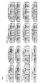
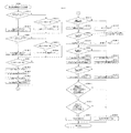
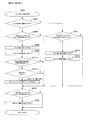
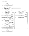
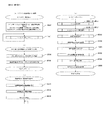
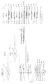
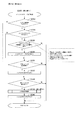
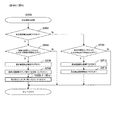
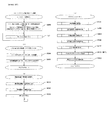
次に、図7のブロック図を参照しながら、本実施形態に係るぱちんこ遊技機の各種機能について説明する。はじめに、主制御基板Mは、遊技に係る遊技周辺機器(第1主遊技周辺機器A、第2主遊技周辺機器B、第1・第2主遊技共用周辺機器C、補助遊技周辺機器H)、演出に係るサブメイン制御部SM(副遊技制御手段SM)、主制御基板Mからの払出指示に基づき所定数の賞球の払出制御を行う賞球払出制御基板KHと、情報伝達可能に接続されている。また、サブメイン制御部SM(副遊技制御手段SM)は、画像演出を実行するサブサブ制御部SS(演出表示手段SS)、各種遊技効果ランプD26(例えばサイドランプ)や枠装飾ランプD18‐L、スピーカD24等とも電気的に接続されている。更に、賞球払出制御基板KHは、ステッピングモータやスプロケット等を備えた賞球払出装置KEと電気的に接続されている。尚、主制御基板M、サブメイン制御部SM(副遊技制御手段SM)、サブサブ制御部SS(演出表示手段SS)、賞球払出制御基板KH等は、ハードウエア的にはデ‐タやプログラムを格納するROMやRAM、演算処理に用いるCPU等の素子等から構成される。尚、以下で主制御基板Mに含まれるとする各手段を周辺機器(例えば、遊技周辺機器)に搭載される形で構成してもよい。例えば、周辺機器(例えば、遊技周辺機器)に含まれるとする各手段を主制御基板Mに搭載される形で構成してもよい。以下、上記各手段(装置)の詳細を説明する。 Next, various functions of the pachinko gaming machine according to the present embodiment will be described with reference to the block diagram of FIG. First, the main control board M is a game peripheral device related to the game (first main game peripheral device A, second main game peripheral device B, first and second main game shared peripheral device C, auxiliary game peripheral device H), A sub-main control unit SM (sub-game control means SM) related to the performance is connected to a prize ball payout control board KH that performs payout control of a predetermined number of prize balls based on a payout instruction from the main control board M so that information can be transmitted. ing. The sub-main control unit SM (sub-game control means SM) includes a sub-sub control unit SS (effect display means SS) for executing image effects, various game effect lamps D26 (for example, side lamps), frame decoration lamps D18-L, The speaker D24 and the like are also electrically connected. Further, the prize ball payout control board KH is electrically connected to a prize ball payout device KE including a stepping motor, a sprocket, and the like. The main control board M, sub-main control part SM (sub-game control means SM), sub-sub control part SS (effect display means SS), prize ball payout control board KH, etc. are data and programs in hardware. ROM, RAM, and elements such as a CPU used for arithmetic processing. In the following description, each means included in the main control board M may be configured to be mounted on a peripheral device (for example, a game peripheral device). For example, each means that is included in a peripheral device (for example, a game peripheral device) may be configured to be mounted on the main control board M. The details of each means (device) will be described below.
まず、主制御基板Mは、遊技用の情報の取得を制御する遊技用情報制御手段MJと、遊技の内容を決定するための遊技内容決定手段MNと、特別遊技や特定遊技等の遊技の進行を司る遊技進行手段MPと、遊技状態等に係る情報を一時記憶するための遊技状態一時記憶手段MBと、遊技機が検知したエラーや不正行為に関する処理を司る不正検知情報管理手段ME(及び、エラー検知や不正検知に係る情報を一時記憶するための不正関連情報一時記憶手段MEb)と、各種入球口への入球状況を計測する、又は、各種入球口への入球状況に係る表示を実行する処理を司るメンテナンスモード制御手段MOと、遊技周辺機器側(特に、サブメイン制御部SM側)に各種遊技情報{例えば、停止図柄情報、停止図柄の属性情報{例えば、16R大当り、8R大当り、4R大当り、ハズレ}、変動態様に関する情報(例えば、変動時間)、特別遊技の開始信号・状態情報・終了信号、保留情報等}を送信するための情報送信制御手段MT(及び未送信コマンドを蓄積するコマンド送信用バッファMT10)と、遊技に係る情報を、外部中継端子板Gを介してホールコンピュータHCに出力する外部信号出力制御手段MGと、各種入賞口への遊技球の入賞に基づき所定の賞球の払出を行うように賞球払出制御基板KHを制御する賞球払出決定手段MHと、を有している。 First, the main control board M has a game information control means MJ for controlling the acquisition of game information, a game content determination means MN for determining the contents of the game, and the progress of games such as special games and specific games. A game progress means MP for managing the game, a game state temporary storage means MB for temporarily storing information relating to the game state, and the fraud detection information management means ME (and The fraud related information temporary storage means MEb) for temporarily storing information related to error detection and fraud detection, and the state of entry into various entrances, or the state of entrance into various entrances Maintenance mode control means MO that controls display and various game information {for example, stop symbol information, stop symbol attribute information {for example, 16R large size) on the game peripheral device side (particularly on the sub-main control unit SM side) Information transmission control means MT for transmitting 8R big hit, 4R big hit, losing}, information on fluctuation mode (for example, fluctuation time), special game start signal / status information / end signal, hold information, etc.} A command transmission buffer MT10 for accumulating unsent commands, an external signal output control means MG for outputting information relating to the game to the hall computer HC via the external relay terminal board G, and game balls to various winning holes And a prize ball payout determining means MH for controlling the prize ball payout control board KH so as to pay out a predetermined prize ball based on the winning.
ここで、遊技用情報制御手段MJは、各入球口(始動口等)への遊技球の流入を判定するための入球判定手段MJ10と、各乱数の取得可否を判定し、当該判定結果に基づき当該各乱数を取得するための乱数取得判定実行手段MJ20と、変動表示中における各始動口への入球を保留球として上限個数以内で一時記憶するための保留制御手段MJ30と、を有している。以下、各手段について詳述する。 Here, the game information control means MJ determines whether or not each random number can be acquired, and the entrance determination means MJ10 for determining the inflow of game balls to each entrance (starting opening, etc.), and the determination result Random number acquisition determination execution means MJ20 for acquiring each random number based on the above, and holding control means MJ30 for temporarily storing the ball entering each starting port during the variable display as a holding ball within the upper limit number. doing. Hereinafter, each means will be described in detail.
まず、入球判定手段MJ10は、第1主遊技始動口A10(及び、第1主遊技始動口確認センサA11s2)に遊技球が入球したか否かを判定する第1主遊技始動口入球判定手段MJ11‐Aと、第2主遊技始動口B10に遊技球が入球したか否かを判定する第2主遊技始動口入球判定手段MJ11‐Bと、補助遊技始動口H10に遊技球が流入したか否かを判定する補助遊技始動口入球判定手段MJ11‐Hと、第1大入賞口C10に遊技球が入球したか否かを判定する、第1大入賞口入球判定手段MJ11‐C10と、第2大入賞口C20に遊技球が入球したか否かを判定する、第2大入賞口入球判定手段MJ11‐C20と、一般入賞口P10に遊技球が入球したか否かを判定する、一般入賞口入球判定手段MJ11‐Pと、アウト口C80に遊技球が入球したか否かを判定する、アウト口入球判定手段MJ11‐C80と、総排出確認センサC90sに遊技球が入球(排出を検出)したか否かを判定する、総排出確認手段MJ11‐C90(及び、当該入球数を計数する、総排出確認数カウンタMJ11c‐C90)と、入球口への入球に係る情報を一時記憶するための入球関連情報一時記憶手段MJ10bと、特定の状況下(例えば、非確率変動遊技状態且つ非時間短縮遊技状態等の特定の遊技状態、等)において第1主遊技始動口A10又は第2主遊技始動口B10に入球した遊技球数を計測する始動口入球数カウンタMJ12cと、特定の状況下(例えば、非確率変動遊技状態且つ非時間短縮遊技状態等の特定の遊技状態、等)において一般入賞口P10に入球した遊技球数を計測する一般入球数カウンタMJ13cと、を有している。 First, the entrance determination means MJ10 determines whether or not a game ball has entered the first main game start port A10 (and the first main game start port confirmation sensor A11s2). Determining means MJ11-A, second main game start opening entrance determining means MJ11-B for determining whether or not a game ball has entered the second main game start opening B10, and a game ball in the auxiliary game start opening H10 Auxiliary game start port entrance determining means MJ11-H for determining whether or not a game has entered, and a first grand entrance entrance determination to determine whether or not a game ball has entered the first major entrance C10 Means MJ11-C10 and whether or not a game ball has entered the second grand prize opening C20, whether or not a game ball has entered the second big prize mouth entry judgment means MJ11-C20 and the general prize opening P10 General winning entry entrance judging means MJ11-P for judging whether or not, and the exit It is determined whether or not a game ball has entered (detected discharge) the out-entry ball entry determination means MJ11-C80, which determines whether or not a game ball has entered 80, and the total discharge confirmation sensor C90s. Total discharge confirmation means MJ11-C90 (and a total discharge confirmation number counter MJ11c-C90 that counts the number of incoming balls) and temporary information related to the entry for temporarily storing information related to entering the entrance Enter the first main game start port A10 or the second main game start port B10 in the storage means MJ10b and in a specific situation (for example, a specific game state such as a non-stochastic game state and a non-time-reduced game state, etc.) The starting entrance entrance number counter MJ12c that measures the number of played balls and the general winning entrance P10 in a specific situation (for example, a specific game state such as a non-stochastic game state and a non-time-reduced game state, etc.) Entered the ball It has a generally ball entrance counter MJ13c for measuring the number of tricks sphere, the.
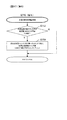
次に、乱数取得判定実行手段MJ20は、第1主遊技始動口A10への遊技球の入球に基づき第1主遊技側乱数を取得するか否かを判定すると共に、判定結果に応じて当該乱数(例えば、第1当選乱数、第1変動態様決定乱数、第1主遊技図柄決定乱数等)を取得する第1主遊技乱数取得判定実行手段MJ21‐Aと、第2主遊技始動口B10への遊技球の入球に基づき第2主遊技側乱数を取得するか否かを判定すると共に、判定結果に応じて当該乱数(例えば、第2当選乱数、第2変動態様決定乱数、第2主遊技図柄決定乱数等)を取得する第2主遊技乱数取得判定実行手段MJ21‐Bと、補助遊技側乱数の取得の可否を判定し、当該判定結果に基づき当該乱数を取得するための補助遊技乱数取得判定実行手段MJ21‐Hと、を有している。 Next, the random number acquisition determination execution means MJ20 determines whether or not to acquire the first main game side random number based on the game ball entering the first main game start opening A10, and according to the determination result, To first main game random number acquisition determination execution means MJ21-A for acquiring random numbers (for example, first winning random number, first variation mode determining random number, first main game symbol determining random number, etc.) and second main game starting port B10 And determining whether or not to acquire the second main game random number based on the incoming game ball, and depending on the determination result, the random number (for example, the second winning random number, the second variation mode determining random number, the second main random number, A second main game random number acquisition determination execution means MJ21-B for acquiring a game symbol determination random number and the like, and an auxiliary game random number for determining whether or not the auxiliary game side random number can be acquired and acquiring the random number based on the determination result Acquisition determination execution means MJ21-H That.
ここで、上記を含め本特許請求の範囲及び本明細書における「乱数」は、例えば、乱数の種類(例えば、当選乱数や変動態様決定乱数)により割り振られた「0」〜「65535」や「0」〜「255」といった所定範囲からランダムに選択された値である。また、乱数としては、数学的に発生させる乱数でなくともよく、ハードウエア乱数やソフトウエア乱数等により発生させる擬似乱数でもよい。例えば、乱数にある夫々の値の発現方式が、乱数の数列に沿って順々に値を発現させる方式(プラスワン方式)、乱数の数列の最終値が発現したときの次の値(初期値)を偶然性のある値によって定める方式(初期値更新方式)、これらの組み合わせ等を挙げることができる。 Here, the “random number” in the claims and the present specification including the above is “0” to “65535” or “ It is a value randomly selected from a predetermined range such as “0” to “255”. The random number may not be a mathematically generated random number, but may be a pseudo random number generated by a hardware random number, a software random number, or the like. For example, the expression method of each value in the random number is a method in which the value is expressed in order along the random number sequence (plus one method), the next value when the final value of the random number sequence is expressed (initial value) ) With a contingent value (initial value update method), a combination of these, and the like.
次に、保留制御手段MJ30は、保留消化及び変動開始に係る処理を制御する保留消化制御手段MJ31と、第1主遊技図柄の変動許可が下りていない状況で取得した当該第1主遊技側乱数を一時記憶するか否かを判定し、当該判定結果に基づき前記乱数を第1主遊技図柄の変動許可が下りるまで第1主遊技図柄保留情報一時記憶手段MJ32b‐Aに保留するための第1主遊技図柄保留手段MJ32‐Aと、第2主遊技図柄の変動許可が下りていない状況で取得した当該第2主遊技側乱数を一時記憶するか否かを判定し、当該判定結果に基づき前記乱数を第2主遊技図柄の変動許可が下りるまで第2主遊技図柄保留情報一時記憶手段MJ32b‐Bに保留するための第2主遊技図柄保留手段MJ32‐Bと、補助遊技図柄の変動許可が下りていない状況で取得した補助遊技側乱数を一時記憶するか否かを判定し、当該判定結果に基づき当該乱数を補助遊技図柄の変動許可が下りるまで補助遊技図柄保留情報一時記憶手段MJ32b‐Hに保留するための補助遊技図柄保留手段MJ32‐Hと、を有している。 Next, the hold control means MJ30 and the hold digest control means MJ31 for controlling the processing related to the hold digest and the fluctuation start, and the first main game random number obtained in a situation where the change permission of the first main game symbol is not given. Is stored temporarily in the first main game symbol holding information temporary storage means MJ32b-A until permission to change the first main game symbol is granted based on the determination result. It is determined whether or not to temporarily store the second main game random number acquired in a situation where the main game symbol holding means MJ32-A and the second main game symbol variation permission is not given, and based on the determination result The second main game symbol holding means MJ32-B for holding random numbers in the second main game symbol holding information temporary storage means MJ32b-B until the second main game symbol change permission is lowered, and the auxiliary game symbol change permission is Going down It is determined whether or not to temporarily store the auxiliary game side random number acquired in the situation where there is not, and based on the determination result, the random number is held in the auxiliary game symbol hold information temporary storage means MJ32b-H until the change permission of the auxiliary game symbol is granted Auxiliary game symbol holding means MJ32-H for performing the game.
ここで、保留消化制御手段MJ31は、変動を開始する条件を充足したか否かを判定する変動開始条件充足判定手段MJ31jを有している。 Here, the pending digest control means MJ31 has a change start condition satisfaction determination means MJ31j for determining whether or not a condition for starting change is satisfied.
次に、第1主遊技図柄保留手段MJ32‐A、第2主遊技図柄保留手段MJ32‐B及び補助遊技図柄保留手段MJ32‐Hは、最大4個まで記憶可能な、前記乱数を保留順序と結合した形で一時記憶するための、第1主遊技図柄保留情報一時記憶手段MJ32b‐A、第2主遊技図柄保留情報一時記憶手段MJ32b‐B及び補助遊技図柄保留情報一時記憶手段MJ32b‐Hを夫々有している。 Next, the first main game symbol holding means MJ32-A, the second main game symbol holding means MJ32-B and the auxiliary game symbol holding means MJ32-H can store a maximum of four, and combine the random numbers with the holding order. The first main game symbol hold information temporary storage means MJ32b-A, the second main game symbol hold information temporary storage means MJ32b-B and the auxiliary game symbol hold information temporary storage means MJ32b-H for temporarily storing in the form Have.
次に、遊技内容決定手段MNは、特別遊技への移行可否及び第2主遊技始動口電動役物B11dの開放可否を抽選する当否抽選手段MN10と、各乱数に基づき、各図柄の停止図柄を決定するための図柄内容決定手段MN40と、各乱数に基づき、各図柄の変動態様(変動時間等)を決定するための変動態様決定手段MN50とを、有している。ここで、当否抽選手段MN10は、第1主遊技図柄に関しての当否抽選を行う第1主遊技当否抽選手段MN11‐Aと、第2主遊技図柄に関しての当否抽選を行う第2主遊技当否抽選手段MN11‐Bと、補助遊技図柄に関しての当否抽選を行う補助遊技当否抽選手段MN11‐Hとを、有している。ここで、第1主遊技当否抽選手段MN11‐A、第2主遊技当否抽選手段MN11‐B及び補助遊技当否抽選手段MN11‐Hは、第1主遊技図柄に関しての当否抽選を行う際に参照される第1主遊技用当否抽選テーブルMN11ta‐Aと、第2主遊技図柄に関しての当否抽選を行う際に参照される第2主遊技用当否抽選テーブルMN11ta‐Bと、補助遊技図柄に関しての当否抽選を行う際に参照される補助遊技用当否抽選テーブルMN11ta‐Hを夫々有している。尚、詳細なテーブル構成の一例については後述する。 Next, the game content determination means MN draws a stop symbol for each symbol based on each random number and a random determination means MN10 for lottery whether or not to shift to the special game and whether or not the second main game start opening electrical accessory B11d is open. Symbol content determining means MN40 for determining, and variation mode determining means MN50 for determining a variation mode (variation time, etc.) of each symbol based on each random number. Here, the success / failure lottery means MN10 is a first main game winner / rejection lottery means MN11-A that performs a success / failure lottery on the first main game symbol, and a second main game winner / rejection lottery unit that performs a success / failure lottery on the second main game symbol. It has MN11-B, and auxiliary game winning / failing lottery means MN11-H for making a winning / losing lottery regarding the auxiliary game symbols. Here, the first main game success / failure lottery means MN11-A, the second main game winner / rejection lottery means MN11-B, and the auxiliary game success / failure lottery means MN11-H are referred to when performing the success / failure lottery with respect to the first main game symbol. The first main game success / failure lottery table MN11ta-A, the second main game success / failure lottery table MN11ta-B referred to when performing the success / failure lottery on the second main game symbol, and the auxiliary game symbol on / off lottery Each of which has an auxiliary gaming success / failure lottery table MN11ta-H that is referred to when performing. An example of a detailed table configuration will be described later.
次に、図柄内容決定手段MN40は、取得した遊技内容決定乱数(第1主遊技乱数)に基づき、第1主遊技図柄の停止図柄を決定する第1主遊技図柄決定手段MN41‐Aと、取得した遊技内容決定乱数(第2主遊技乱数)に基づき、第2主遊技図柄の停止図柄を決定する第2主遊技図柄決定手段MN41‐Bと、取得した補助遊技図柄当選乱数に基づき補助遊技図柄の停止図柄を決定する補助遊技図柄決定手段MN41‐Hと、を有している。 Next, the symbol content determination means MN40 and the first main game symbol determination means MN41-A for determining the stop symbol of the first main game symbol based on the acquired game content determination random number (first main game random number) and the acquisition Based on the determined game content determination random number (second main game random number), the second main game symbol determining means MN41-B for determining the stop symbol of the second main game symbol, and the auxiliary game symbol based on the acquired auxiliary game symbol winning random number Auxiliary game symbol determining means MN41-H for determining the stop symbol of the game.
ここで、第1主遊技図柄決定手段MN41‐Aは、第1主遊技図柄に係る停止図柄を決定する際に参照される第1主遊技図柄決定用抽選テーブルMN41ta‐Aを有しており、当該第1主遊技図柄決定用抽選テーブルMN41ta‐Aは、当否結果に応じて異なる各種抽選テーブルを備えている。また、第2主遊技図柄決定手段MN41‐Bは、第2主遊技図柄に係る停止図柄を決定する際に参照される第2主遊技図柄決定用抽選テーブルMN41ta‐Bを有しており、当該第2主遊技図柄決定用抽選テーブルMN41ta‐Bは、当否結果に応じて異なる各種抽選テーブルを備えている。更に、補助遊技図柄決定手段MN41‐Hは、補助遊技図柄に係る停止図柄を決定する際に参照される補助遊技図柄決定用抽選テーブルMN41ta‐Hを有しており、当該補助遊技図柄決定用抽選テーブルMN41ta‐Hは、遊技状態に応じて異なる各種当選テーブルを備えている。尚、詳細なテーブル構成の一例については後述する。 Here, the first main game symbol determination means MN41-A has a first main game symbol determination lottery table MN41ta-A referred to when determining a stop symbol related to the first main game symbol, The first main game symbol determination lottery table MN41ta-A includes various lottery tables that differ depending on the result of the determination. The second main game symbol determination means MN41-B has a second main game symbol determination lottery table MN41ta-B that is referred to when determining a stop symbol related to the second main game symbol. The second main game symbol determination lottery table MN41ta-B is provided with various lottery tables that differ depending on the result. Further, the auxiliary game symbol determination means MN41-H has an auxiliary game symbol determination lottery table MN41ta-H which is referred to when determining a stop symbol related to the auxiliary game symbol. The table MN41ta-H includes various winning tables that differ depending on the gaming state. An example of a detailed table configuration will be described later.
次に、変動態様決定手段MN50は、取得した遊技内容決定乱数(第1主遊技乱数)に基づき、第1主遊技図柄の変動態様(変動時間等)を決定する第1主遊技変動態様決定手段MN51‐Aと、取得した遊技内容決定乱数(第2主遊技乱数)に基づき、第2主遊技図柄の変動態様(変動時間等)を決定する第2主遊技変動態様決定手段MN51‐Bと、取得した補助遊技図柄当選乱数に基づき補助遊技図柄の変動態様(変動時間等)を決定する補助遊技変動態様決定手段MN51‐Hと、を有している。 Next, the variation mode determination unit MN50 determines the variation mode (variation time, etc.) of the first main game symbol based on the acquired game content determination random number (first primary game random number). MN 51-A and second main game variation mode determination means MN51-B for determining a variation mode (variation time, etc.) of the second main game symbol based on the acquired game content determination random number (second main game random number), And auxiliary game variation mode determining means MN51-H for determining the variation mode (variation time, etc.) of the auxiliary game symbol based on the acquired auxiliary game symbol winning random number.
ここで、第1主遊技変動態様決定手段MN51‐Aは、第1主遊技図柄に係る変動態様を決定する際に参照される第1主遊技変動態様決定用抽選テーブルMN51ta‐Aを有しており、当該第1主遊技変動態様決定用抽選テーブルMN51ta‐Aは、当否結果・遊技状態に応じて異なる各種抽選テーブルを備えている。また、第2主遊技変動態様決定手段MN51‐Bは、第2主遊技図柄に係る変動態様を決定する際に参照される第2主遊技変動態様決定用抽選テーブルMN51ta‐Bを有しており、当該第2主遊技変動態様決定用抽選テーブルMN51ta‐Bは、当否結果・遊技状態に応じて異なる各種抽選テーブルを備えている。尚、詳細なテーブル構成の一例については後述する。更に、補助遊技変動態様決定手段MN51‐Hは、補助遊技図柄に係る変動態様を決定する際に参照される補助遊技変動態様決定用抽選テーブルMN51ta‐Hを有しており、当該補助遊技変動態様決定用抽選テーブルMN51ta‐Hは、遊技状態に応じて異なる各種当選テーブルを備えている(例えば、通常遊技→補助遊技通常用抽選テーブル、確率変動遊技及び時間短縮遊技→補助遊技時間短縮用抽選テーブル)。 Here, the first main game variation mode determination means MN51-A has a first main game variation mode determination lottery table MN51ta-A that is referred to when determining the variation mode related to the first main game symbol. The first main game variation mode determination lottery table MN51ta-A includes various lottery tables that differ depending on the result of the success / failure and the game state. The second main game variation mode determination means MN51-B has a second main game variation mode determination lottery table MN51ta-B which is referred to when determining the variation mode related to the second main game symbol. The second main game variation mode determination lottery table MN51ta-B includes various lottery tables that differ depending on the result of the success / failure and the game state. An example of a detailed table configuration will be described later. Further, the auxiliary game variation mode determination means MN51-H has an auxiliary game variation mode determination lottery table MN51ta-H that is referred to when determining the variation mode related to the auxiliary game symbol. The determination lottery table MN51ta-H includes various winning tables that differ depending on the game state (for example, normal game → auxiliary game normal lottery table, probability variation game and time shortening game → auxiliary game time shortening lottery table. ).
次に、表示制御手段MP10は、第1主遊技図柄表示装置A20の第1主遊技図柄表示部A21g上及び第2主遊技図柄表示装置B20の第2主遊技図柄表示部B21g上で、所定時間第1主遊技図柄を変動させた後に停止表示する制御を行う第1・第2主遊技図柄制御手段MP11‐Cと、補助遊技図柄表示装置H20の補助遊技図柄表示部H21g上で、所定時間補助遊技図柄を変動させた後に停止表示する制御を行う補助遊技図柄制御手段MP11‐Hとを有している。 Next, the display control means MP10 performs a predetermined time on the first main game symbol display unit A21g of the first main game symbol display device A20 and on the second main game symbol display unit B21g of the second main game symbol display device B20. The first and second main game symbol control means MP11-C for controlling to stop display after changing the first main game symbol and the auxiliary game symbol display unit H21g of the auxiliary game symbol display device H20 are assisted for a predetermined time. Auxiliary game symbol control means MP11-H for controlling to stop and display after changing the game symbol is provided.
ここで、第1・第2主遊技図柄制御手段MP11‐Cは、ゼロクリア可能な第1・第2主遊技図柄変動管理用タイマMP11t‐C(例えば、所定間隔毎に減算されるデクリメントカウンタであり、以下、タイマに類するものは同様のカウンタにて実装可能)を有している。更に、補助遊技図柄制御手段MP11‐Hは、時間を計測可能な補助遊技図柄変動管理用タイマMP11t‐Hを更に備えている。 Here, the first and second main game symbol control means MP11-C is a zero / clearable first and second main game symbol variation management timer MP11t-C (for example, a decrement counter that is subtracted at predetermined intervals). Hereinafter, those similar to timers can be mounted with the same counter). Further, the auxiliary game symbol control means MP11-H further includes an auxiliary game symbol variation management timer MP11t-H capable of measuring time.
次に、第2主遊技始動口電動役物開閉制御手段MP20‐Bは、第2主遊技始動口電動役物B11dを開閉する処理を行うための条件を充足しているか否かを判定するための第2主遊技始動口電動役物開閉条件判定手段MP21‐Bと、第2主遊技始動口電動役物B11dの駆動(開放)時間を計測する第2主遊技始動口電動役物開放タイマMP22t‐Bと、第2主遊技始動口電動役物B11dの閉鎖後に第2主遊技始動口電動役物B11d内に残存している遊技球が第2主遊技始動口入球検出装置B11sに検出されるまで待機する時間を計時する、第2主遊技始動口入球待機タイマMP22t2と、を有している。 Next, the second main game start opening electric accessory opening / closing control means MP20-B determines whether or not the condition for performing the process of opening / closing the second main game start opening electric accessory B11d is satisfied. The second main game start port electric player opening / closing condition determining means MP21-B and the second main game start port electric player opening timer MP22t for measuring the driving (opening) time of the second main game start port electric player B11d -B and the game ball remaining in the second main game start port electric accessory B11d after the second main game start port electric accessory B11d is closed are detected by the second main game start port entrance detecting device B11s. And a second main game start opening entrance waiting timer MP22t2, which measures the time to wait until
次に、特別遊技制御手段MP30は、特別遊技に移行するための条件を充足しているか否かを判定する条件判定手段MP31と、特別遊技移行条件を充足している場合、当該特別遊技の内容(具体的には、開状態となる大入賞口、ラウンド数、ラウンド間時間等)を決定し、特別遊技関連情報一時記憶手段MB20b内にセットする特別遊技内容決定手段MP32と、第1大入賞口C10又は第2大入賞口C20を所定条件で開状態にする特別遊技(大当り)を実行するための特別遊技実行手段MP33と、特別遊技に関する各種処理の時間管理(例えば、第1大入賞口C10及び第2大入賞口C20の開閉時間)を行うための特別遊技時間管理手段MP34と、振分遊技を実行するための振分遊技実行制御手段MP36と、を有している。ここで、特別遊技実行手段MP33は、第1大入賞口電動役物C11dと第2大入賞口電動役物C21dを開閉させる第1・第2大入賞口電動役物開閉制御手段MP33‐Cと、第1大入賞口C10と第2大入賞口C20への入賞球を計測する入賞球カウンタMP33cを有している。特別遊技時間管理手段MP34は、ラウンド時間を管理する特別遊技用タイマMP34tと、大入賞口の開放時間を計時する開放タイマMP34t2と、第1大入賞口C10(又は第2大入賞口C20)の閉鎖後に第1大入賞口C10(又は第2大入賞口C20)内に残存している遊技球が第1大入賞口入賞検出装置C11s(又は第2大入賞口入賞検出装置C21s)に検出されるまで待機する時間を計時する、大入賞口入球待機タイマMP34t3と、を更に有している。また、特別遊技内容決定手段MP32は、特別遊技関連情報一時記憶手段MB20bにセットされるべき前記特別遊技の内容を特定する際に参照される特別遊技内容参照テーブルMP32taを更に有している(テーブルの詳細については不図示であるが、開状態となる大入賞口、最大ラウンド数、1ラウンドの実行内容等が定められたテーブルである。また、特別遊技が開始されてから初回のラウンドが実行されるまでの待機時間である開始デモ時間、最終回のラウンドが終了してから特別遊技を終了するまでの待機時間である終了デモ時間、等も本テーブルにて予め定められている)。 Next, when the special game control means MP30 satisfies the condition determination means MP31 for determining whether or not the condition for shifting to the special game is satisfied, and the special game transfer condition, the contents of the special game (Specifically, the big winning opening to be opened, the number of rounds, the time between rounds, etc.) are determined and set in the special game related information temporary storage means MB20b. Special game execution means MP33 for executing a special game (big hit) for opening the mouth C10 or the second grand prize port C20 in a predetermined condition, and time management of various processes related to the special game (for example, the first grand prize port) Special game time management means MP34 for performing the opening / closing time of C10 and the second big prize opening C20), and distribution game execution control means MP36 for executing the distribution game. Here, the special game executing means MP33 includes first and second prize winning opening electric accessory opening / closing control means MP33-C for opening and closing the first prize winning opening electric accessory C11d and the second prize winning opening electric accessory C21d. , A winning ball counter MP33c for measuring winning balls to the first big winning opening C10 and the second big winning opening C20 is provided. The special game time management means MP34 includes a special game timer MP34t for managing the round time, an opening timer MP34t2 for measuring the opening time of the big winning opening, and the first big winning opening C10 (or the second big winning opening C20). The game balls remaining in the first grand prize opening C10 (or the second big prize opening C20) after the closing are detected by the first big prize opening prize detection device C11s (or the second big prize opening prize detection device C21s). It further has a special winning opening entrance waiting timer MP34t3 that measures the time to wait until the game is completed. The special game content determination means MP32 further includes a special game content reference table MP32ta that is referred to when specifying the content of the special game to be set in the special game related information temporary storage means MB20b (table) The details of are not shown, but are a table in which the open prize opening, the maximum number of rounds, the execution contents of one round, etc. are determined, and the first round is executed after the special game is started The start demo time, which is the waiting time until the game is played, the end demo time, which is the wait time from the end of the final round to the end of the special game, and the like are also predetermined in this table).
次に、特定遊技制御手段MP50は、確率変動遊技状態の終了条件を充足しているか否かを判定する確変終了条件判定手段MP51と、時間短縮遊技状態の終了条件を充足しているか否かを判定する時短終了条件判定手段MP52を有している。時短回数をカウント可能な時短回数カウンタMP52c、を夫々有している。ここで、確率変動遊技状態とは、第1主遊技図柄及び第2主遊技図柄の当否抽選時における当選確率が非確率変動遊技状態よりも高確率となる遊技状態を意味し、時間短縮遊技状態とは、第1主遊技図柄や第2主遊技図柄の変動時間の平均値が非時間短縮遊技状態よりも短時間となる、及び/又は、単位時間あたりにおける第2主遊技始動口電動役物B11dの開放容易性が向上する遊技状態を意味する。 Next, the specific game control means MP50 determines whether or not the probability variation end condition determination means MP51 for determining whether or not the end condition for the probability variation game state is satisfied, and whether or not the end condition for the time-reduced game state is satisfied. It has a short time end condition determination means MP52 for determination. Each has a short time counter MP52c capable of counting the short time. Here, the probability variation gaming state means a gaming state in which the winning probability at the time of winning or failing the first main gaming symbol and the second main gaming symbol is higher than the non-stochastic variation gaming state, and the time shortening gaming state Means that the average value of the variation time of the first main game symbol and the second main game symbol is shorter than the non-time-reduced game state, and / or the second main game start opening electric accessory per unit time It means a gaming state in which the ease of opening B11d is improved.
ここで、本実施形態においては、時間短縮遊技中には、非時間短縮遊技中と比較して、第1主遊技図柄及び第2主遊技図柄の変動時間が相対的に短縮される(時間短縮機能)。更に、補助遊技図柄が高確率で当り図柄となり且つ補助遊技図柄の変動時間も相対的に短縮されると共に、第2主遊技始動口電動役物B11dの開放延長時間が相対的に延長される(開放時間延長機能)。また、本実施形態における時間短縮遊技は、第1主遊技図柄の変動回数と第2主遊技図柄の変動回数の合計値が所定回数を超えた場合に終了する(時短回数制限無しの確率変動遊技を除く)。即ち、時短回数は、第1主遊技図柄及び第2主遊技図柄の変動(停止)毎に減算されるよう構成されている。尚、上記の確変終了条件判定手段MP51及び時短終了条件判定手段MP52は、例えば、図柄変動の度に所定確率で特定遊技(例えば確率変動遊技や時間短縮遊技)から通常遊技への移行抽選を行う機能を有していてもよい(いわゆる、転落抽選機能を有するぱちんこ遊技機の場合)。 Here, in the present embodiment, during the time reduction game, the variation time of the first main game symbol and the second main game symbol is relatively shortened (time reduction) compared to during the non-time reduction game. function). Further, the auxiliary game symbol becomes a winning symbol with a high probability, and the variation time of the auxiliary game symbol is relatively shortened, and the opening extension time of the second main game start opening electric accessory B11d is relatively prolonged ( Opening time extension function). Also, the time-reduced game in the present embodiment ends when the total value of the number of changes of the first main game symbol and the number of times of change of the second main game symbol exceeds a predetermined number (probability variation game with no time limit restriction). except for). That is, the number of time reductions is configured to be subtracted every time the first main game symbol and the second main game symbol fluctuate (stop). Note that the probability variation end condition determination means MP51 and the short time end condition determination means MP52 perform, for example, a lottery to shift from a specific game (for example, a probability variation game or a time-reduced game) to a normal game with a predetermined probability every time the symbol changes. It may have a function (in the case of a pachinko game machine having a so-called falling lottery function).
次に、遊技状態一時記憶手段MBは、第1主遊技(第1主遊技図柄の変動から停止に至るまでの遊技)及び第2主遊技(第2主遊技図柄の変動から停止に至るまでの遊技)における現在の遊技状態を一時記憶するための第1・第2主遊技状態一時記憶手段MB10‐Cと、補助遊技における現在の遊技状態を一時記憶するための補助遊技状態一時記憶手段MB10‐Hと、特別遊技における現在の遊技状態(例えば、ラウンド数、任意のラウンドにおける遊技球の入賞個数、特別遊技に関する各種フラグのオン・オフ等)を一時記憶するための特別遊技関連情報一時記憶手段MB20bと、特定遊技における現在の遊技状態(例えば、時短の残り回数、特定遊技に関する各種フラグのオン・オフ等)を一時記憶するための特定遊技関連情報一時記憶手段MB30bと、を有している。 Next, the game state temporary storage means MB includes the first main game (game from the change of the first main game symbol to the stop) and the second main game (from the change of the second main game symbol to the stop). First and second main game state temporary storage means MB10-C for temporarily storing the current game state in the game) and auxiliary game state temporary storage means MB10- for temporarily storing the current game state in the auxiliary game Special game-related information temporary storage means for temporarily storing H and the current game state in the special game (for example, the number of rounds, the number of winning game balls in an arbitrary round, on / off of various flags related to special games, etc.) Specific game-related information for temporarily storing the MB20b and the current game state in the specific game (for example, the remaining number of time reductions, ON / OFF of various flags related to the specific game, etc.) Has a storage means MB30b, the.
ここで、第1・第2主遊技状態一時記憶手段MB10‐Cは、現在変動中の第1又は第2主遊技図柄(変動開始条件が成立した第1又は第2主遊技図柄)に係る停止図柄及び変動態様情報を一時記憶するための第1・第2主遊技図柄情報一時記憶手段MB11b‐Cを有している。 Here, the first and second main game state temporary storage means MB10-C are stopped according to the first or second main game symbol that is currently changing (the first or second main game symbol that satisfies the change start condition). There are first and second main game symbol information temporary storage means MB11b-C for temporarily storing symbols and variation mode information.
また、補助遊技状態一時記憶手段MB10‐Hは、現在変動中の補助遊技図柄(変動開始条件が成立した補助遊技図柄)に係る停止図柄等の情報を一時記憶するための補助遊技図柄情報一時記憶手段MB11b‐Hを有している。 Further, the auxiliary game state temporary storage means MB10-H temporarily stores auxiliary game symbol information for temporarily storing information such as stop symbols related to the currently changing auxiliary game symbols (auxiliary game symbols for which the change start condition is satisfied). Means MB11b-H.
次に、賞球払出決定手段MHは、賞球払出制御基板KH側との間で賞球の払出(及びエラー検知や不正検知)に係る情報を送受信するための払出情報送受信手段MHsj(及び送受信した情報を一時記憶する払出コマンド一時記憶手段MHsjb)と、遊技球の入球に基づく賞球総数を計数するための賞球数カウンタMHcと、賞球の払出が完了していない(賞球払出制御基板KH側から払出完了に係る情報を受信していない)未払出賞球に係る情報を一時記憶するための未払出賞球情報一時記憶手段MHbと、を有している。 Next, the prize ball payout determining means MH sends and receives payout information transmission / reception means MHsj (and transmission / reception) for sending and receiving information relating to the prize ball payout (and error detection and fraud detection) with the prize ball payout control board KH side. A payout command temporary storage means MHsjb) for temporarily storing the received information, a prize ball number counter MHc for counting the total number of prize balls based on the entry of game balls, and the prize ball payout has not been completed (prize ball payout) Unpaid prize ball information temporary storage means MHb for temporarily storing information relating to unpaid prize balls (which has not received information relating to the completion of withdrawal from the control board KH side).
次に、遊技周辺機器について説明する。尚、一部の周辺機器については既に詳細構成を述べたので、残る構成について簡潔に説明する。まず、遊技周辺機器は、第1主遊技側の周辺機器である第1主遊技周辺機器Aと、第2主遊技側の周辺機器である第2主遊技周辺機器Bと、第1主遊技側と第2主遊技側の共用周辺機器である第1・第2主遊技共用周辺機器Cと、補助遊技に関する補助遊技周辺機器Hと、副遊技制御手段(サブメイン制御部)SM、サブサブ制御部SS(及び演出表示装置SG)等、を有している。ここで、サブメイン制御部SMにより制御される演出は、第1主遊技図柄及び第2主遊技図柄の変動と時間的に同期の取れた形での装飾図柄の変動を含め、遊技の結果に影響を与えない情報のみの表示に係るものである。以下、これらの周辺機器を順番に説明する。 Next, game peripheral devices will be described. Since some of the peripheral devices have already been described in detail, the remaining configuration will be briefly described. First, the game peripheral devices are a first main game peripheral device A that is a peripheral device on the first main game side, a second main game peripheral device B that is a peripheral device on the second main game side, and a first main game side. First and second main game shared peripheral device C, which is a shared peripheral device on the second main game side, auxiliary game peripheral device H related to auxiliary games, sub game control means (sub main control unit) SM, sub sub control unit SS (and effect display device SG) and the like. Here, the effects controlled by the sub-main control unit SM include the fluctuation of the decoration pattern in a form synchronized in time with the fluctuation of the first main game symbol and the second main game symbol. It concerns only the display of information that has no effect. Hereinafter, these peripheral devices will be described in order.
まず、第1主遊技周辺機器Aは、特別遊技移行の契機となる第1主遊技始動口A10と、第1主遊技図柄の停止表示及び変動表示が可能な第1主遊技図柄表示装置A20と、を有している。尚、第1主遊技始動口A10に関しては、第1主遊技始動口A10への入球を検出するための第1主遊技始動口入球検出装置A11sと、当該入球が正常な入球であるかを確認するための第1主遊技始動口確認センサA11s2とを有しており、いずれかの入球口でのみ(特に、第1主遊技始動口入球検出装置A11sでのみ)入球が検出された場合には、不正行為又はエラー発生に係る処理を実行するよう構成されている(詳細は後述)。尚、このように2つのセンサを用いて入球を二重にチェックする場合、検出の仕組みが異なるセンサ(例えば、非接触型のフォトセンサと、接触型の物理スイッチ)を組み合わせて利用することが、不正行為を検出するためには好適である。 First, the first main game peripheral device A includes a first main game start opening A10 that triggers the transition to a special game, and a first main game symbol display device A20 that can display stop and change display of the first main game symbol. ,have. As for the first main game start opening A10, the first main game start opening entrance detection device A11s for detecting the entry into the first main game start opening A10, and the entry is a normal entry. And a first main game start opening confirmation sensor A11s2 for confirming whether or not there is an entry at any of the entrances (especially only at the first main game start entrance entrance detection device A11s). Is detected, a process related to an illegal act or an error occurrence is executed (details will be described later). When two balls are used to double check the entrance, use sensors with different detection mechanisms (for example, non-contact type photo sensor and contact type physical switch). However, it is suitable for detecting fraud.
次に、第2主遊技周辺機器Bは、特別遊技移行の契機となる第2主遊技始動口B10と、第2主遊技図柄の停止表示及び変動表示が可能な第2主遊技図柄表示装置B20と、を有している。 Next, the second main game peripheral device B has a second main game start port B10 that triggers the transition to the special game, and a second main game symbol display device B20 that can display stop and change display of the second main game symbol. And have.
次に、第1・第2主遊技共用周辺機器Cは、通常遊技の際には閉状態にあり、特別遊技(大当り)の際には所定条件下で開状態となる第1大入賞口C10及び第2大入賞口C20と、遊技球が入賞することにより遊技球を払い出すこととなる一般入賞口P10と、各種入球口への入球状況に関する表示を実行し得る入球状態表示装置J10と、遊技領域D30に発射された遊技球の内始動口や入賞口に入球しなかった遊技球を遊技機内に取り込むためのアウト口C80と、始動口や入球口及びアウト口C80から遊技機内に取り込まれた遊技球を遊技機外に排出する経路上に設けられ、遊技機から排出する遊技球を検出するための総排出確認センサC90sと、を有している。 Next, the first and second main game shared peripheral device C is in a closed state during a normal game, and is opened under a predetermined condition during a special game (big hit). And a second winning prize opening C20, a general winning opening P10 from which a game ball is paid out when a game ball wins, and a ball entry state display device capable of executing a display regarding the state of entry to various entry holes J10, an out port C80 for taking a game ball that has not entered the start port or winning port of the game balls launched into the game area D30 into the gaming machine, and the start port, the entrance port, and the out port C80. A total discharge confirmation sensor C90s that is provided on a path for discharging the game ball taken into the game machine to the outside of the game machine and detects the game ball discharged from the game machine.
次に、補助遊技周辺機器Hは、第2主遊技始動口B10の第2主遊技始動口電動役物B11dの開放の契機となる補助遊技始動口H10と、補助遊技図柄の停止表示及び変動表示が可能な補助遊技図柄表示装置H20とを有している。 Next, the auxiliary game peripheral device H includes the auxiliary game start port H10 that triggers the opening of the second main game start port electric accessory B11d of the second main game start port B10, and the stop display and change display of the auxiliary game symbols. And an auxiliary game symbol display device H20 capable of receiving
次に、演出表示制御手段(サブメイン制御部)SMは、主制御基板M側からの各種情報を受信するための表示情報受信手段SM10と、演出表示に係る演出内容の決定処理及び表示制御処理を司る演出表示制御手段SM20と、エラー発生時のエラー報知を制御するエラー報知制御手段SM30と、サブサブ制御部SS側との情報送受信を制御する情報送受信制御手段SM40と、を有している。以下、上記各手段を詳述する。 Next, the effect display control means (sub-main control unit) SM includes display information receiving means SM10 for receiving various information from the main control board M side, effect content determination processing and display control processing for effect display. Effect display control means SM20 for controlling the error, error notification control means SM30 for controlling error notification when an error occurs, and information transmission / reception control means SM40 for controlling information transmission / reception with the sub-sub control unit SS side. Hereafter, each said means is explained in full detail.
まず、表示情報受信手段SM10は、主制御基板M側からの第1主遊技及び第2主遊技に関する図柄情報や表示指示情報を一時記憶するためのメイン側情報一時記憶手段SM11bを有している。 First, the display information receiving means SM10 has main-side information temporary storage means SM11b for temporarily storing symbol information and display instruction information related to the first main game and the second main game from the main control board M side. .
次に、演出表示制御手段SM20は、装飾図柄の変動態様や停止図柄の決定処理及び表示制御処理を司る装飾図柄表示制御手段SM21と、装飾図柄の保留個数管理や保留表示処理を司る装図保留情報表示制御手段SM22と、背景画像の決定処理及び表示制御処理を司る背景演出表示制御手段SM23と、予告演出内容の決定処理及び表示制御処理を司る予告演出表示制御手段SM24と、リーチ演出内容の決定処理及び表示制御処理を司るリーチ演出表示制御手段SM25と、を有している。 Next, the effect display control means SM20 is a decorative symbol display control means SM21 that controls the decorative pattern variation mode and stop symbol determination processing and display control processing, and the decorative symbol display control processing that holds the decorative symbol hold count management and hold display processing. Information display control means SM22, background effect display control means SM23 for determining background image determination processing and display control processing, notice effect display control means SM24 for controlling determination effect display processing and display control processing, and reach effect content And reach effect display control means SM25 for managing the determination process and the display control process.
次に、エラー報知制御手段SM30は、エラー発生の有無を判定するためのエラー発生判定手段SM31を有している。 Next, the error notification control means SM30 has an error occurrence determination means SM31 for determining whether or not an error has occurred.
ここで、装飾図柄表示制御手段SM21は、主制御基板M側からの情報に基づいて、装飾図柄の停止図柄及び変動態様を決定する装図表示内容決定手段SM21nと、装飾図柄の図柄変動に係る各種情報(変動態様情報、停止図柄情報、各種フラグ等)を一時記憶するための装図表示関連情報一時記憶手段SM21bと、装飾図柄の変動時間を計時するための装図変動時間管理タイマSM21tと、を有している。ここで、装図表示内容決定手段SM21nは、装飾図柄の停止図柄及び変動態様を決定する際に参照される装図変動内容決定用抽選(参照)テーブルSM21taを更に有している(テーブルの詳細については不図示)。 Here, the decorative design display control means SM21 is based on the information from the main control board M side, the display design content determination means SM21n for determining the stop design and the variation mode of the decorative design, and the decorative design display variation SM21n. The drawing display related information temporary storage means SM21b for temporarily storing various information (variation mode information, stop symbol information, various flags, etc.), and the drawing variation time management timer SM21t for timing the variation time of the decorative symbols; ,have. Here, the drawing display content determination means SM21n further includes a drawing variation content determination lottery (reference) table SM21ta that is referred to when determining the stop symbol and variation mode of the decorative symbol (details of the table). (Not shown).
次に、装図保留情報表示制御手段SM22は、装飾図柄に係る保留に関する情報を一時記憶するための装図保留情報一時記憶手段SM22bと、を有している。 Next, the drawing hold information display control means SM22 has a drawing hold information temporary storage means SM22b for temporarily storing information related to the hold related to the decorative design.
次に、背景演出表示制御手段SM23は、主制御基板M側からの情報に基づいて、背景演出(本例では、装飾図柄の背面にて表示され、保留に関する情報に基づき特別遊技の実行可能性を示唆・報知する演出)の表示内容を決定する背景演出表示内容決定手段SM23nと、背景演出表示に係る情報を一時記憶するための背景演出関連情報一時記憶手段SM23bと、を有している。 Next, the background effect display control means SM23 is displayed based on the information from the main control board M side, and the background effect (in this example, it is displayed on the back of the decorative symbol, and the possibility of executing the special game based on the information regarding the hold) Background effect display content determining means SM23n for determining the display content of the effect), and background effect related information temporary storage means SM23b for temporarily storing information related to the background effect display.
次に、予告演出表示制御手段SM24は、主制御基板M側からの情報に基づいて、予告演出(本例では、装飾図柄の変動表示中において表示され、当該変動における特別遊技への移行期待度や、保留に関する情報に基づき特別遊技の実行可能性を示唆・報知する演出)の表示内容や表示タイミング等を決定する予告演出表示内容決定手段SM24nと、予告演出表示に係る情報を一時記憶するための予告演出関連情報一時記憶手段SM24bと、を有している。 Next, the notice effect display control means SM24 is displayed based on the information from the main control board M side, and is displayed during the notice effect (in this example, the decorative symbol is displayed in a variable manner, and the expected degree of transition to the special game in the change) In order to temporarily store the information related to the notice effect display and the notice effect display content determining means SM24n for determining the display content, display timing, etc. of the effect that suggests / informs the feasibility of the special game based on the information related to the hold. The notice effect related information temporary storage means SM24b.
次に、リーチ演出表示制御手段SM25は、主制御基板M側からの情報に基づいて、リーチ演出(主に、装飾図柄の変動表示中において表示され、停止表示された装飾図柄の組み合わせによってリーチ状態となったことが報知された後に実行される演出であるが、リーチ状態とならなくとも装飾図柄の変動表示と連動して実行される演出をも含んでいる)の表示内容や表示タイミング等を決定するリーチ演出表示内容決定手段SM25nと、リーチ演出表示に係る情報を一時記憶するためのリーチ演出関連情報一時記憶手段SM25bと、を有している。 Next, the reach effect display control means SM25, based on the information from the main control board M side, reaches the reach state (mainly during the variable display of the decorative symbols, the reach state by the combination of the decorative symbols that are stopped and displayed This is an effect that is executed after the fact that it has been notified, but it also includes an effect that is executed in conjunction with the change display of the decorative symbol even if it does not reach the reach state) Reach effect display content determining means SM25n to be determined, and reach effect related information temporary storage means SM25b for temporarily storing information related to reach effect display.
次に、演出表示手段(サブサブ制御部)SSは、サブメイン制御部SM側との情報送受信を制御する副情報送受信制御手段SS10と、演出表示装置SG上の表示領域SG10へ画像を表示する画像表示制御手段SS20と、を有している。ここで、画像表示制御手段SS20は、サブメイン制御部SM側から受信したコマンドや各種画像表示に係る情報を一時記憶するための画像表示関連情報一時記憶手段SS21bを更に有している。 Next, the effect display means (sub-sub control part) SS displays an image on the display area SG10 on the effect display device SG and the sub-information transmission / reception control means SS10 that controls information transmission / reception with the sub-main control part SM side. Display control means SS20. Here, the image display control means SS20 further includes image display related information temporary storage means SS21b for temporarily storing commands received from the sub-main control unit SM side and information relating to various image displays.
また、演出表示手段(サブサブ制御部)SSは、演出表示手段(サブサブ制御部)SSからの情報に基づいて演出に係る画像を表示する演出表示装置SGと電気的に接続されている。ここで、演出表示装置SGは、画像を表示する表示領域SG10を有している。 The effect display means (sub-sub control unit) SS is electrically connected to an effect display device SG that displays an image related to the effect based on information from the effect display means (sub-sub control unit) SS. Here, the effect display device SG has a display area SG10 for displaying an image.
ここで、表示領域SG10は、装飾図柄を変動表示するための装飾図柄表示領域SG11と、主遊技保留情報を表示する第1保留表示部SG12(及び第2保留表示部SG13)と、を有している。 Here, the display area SG10 includes a decoration symbol display area SG11 for variably displaying a decoration symbol, and a first hold display portion SG12 (and a second hold display portion SG13) for displaying main game hold information. ing.
尚、第1主遊技図柄表示装置A20、第2主遊技図柄表示装置B20及び補助遊技図柄表示装置H20が、主制御基板Mと情報伝達可能に接続されており、残る演出表示手段(サブサブ制御部)SSが、副遊技制御手段(サブメイン制御部)SMと情報伝達可能に接続されている。即ち、第1主遊技図柄表示装置A20、第2主遊技図柄表示装置B20及び補助遊技図柄表示装置H20は、主制御基板Mにより制御され、演出表示手段(サブサブ制御部)SSは、副遊技制御手段(サブメイン制御部)SMにより制御されることを意味する。尚、主制御基板Mと片方向通信(一方向通信)により制御される他の周辺機器を介して、別の周辺機器を制御するように構成してもよい。 The first main game symbol display device A20, the second main game symbol display device B20, and the auxiliary game symbol display device H20 are connected to the main control board M so as to be able to transmit information, and the remaining effect display means (sub-sub control unit) ) SS is connected to the sub game control means (sub main control unit) SM so that information can be transmitted. That is, the first main game symbol display device A20, the second main game symbol display device B20, and the auxiliary game symbol display device H20 are controlled by the main control board M, and the effect display means (sub-sub control unit) SS is sub-game control. Meaning that it is controlled by means (sub-main control unit) SM. Note that another peripheral device may be controlled via the main control board M and another peripheral device controlled by one-way communication (one-way communication).
次に、図8は、主制御基板Mが行う一般的な処理の流れを示したメインフローチャートである。遊技機の電源投入後、同図(a)の処理が実行される。即ち、遊技機の電源投入後、初期設定を行った後(不図示であるが、レジスタの初期化や入出力ポートの設定等を行う)、ステップ1002で、主制御基板Mは、RAMクリアボタンの入力ポートを確認し、電源供給ユニットEのリセットボタン(RAMクリアボタン)が操作されたか否か、即ち、遊技場の管理者等によって意図的にRAMの内容をクリアさせる操作が行われたか否かを判定する。ステップ1002でYesの場合、ステップ1004で、主制御基板Mは、主制御基板M側のRAM内容(例えば、遊技状態一時記憶手段MB内の情報等)を全てクリアする。次に、ステップ1006で、情報送信制御手段MTは、主制御基板MのRAMをクリアしたことを示すラムクリア情報(コマンド)をサブメイン制御部SM側に送信し(当該タイミングにて送信してもよいし、当該タイミングではコマンドをセットしておき後述する制御コマンド送信処理にて送信するよう構成してもよい)、ステップ1016の処理に移行する。他方、ステップ1002でNoの場合は、ステップ1008で、主制御基板Mは、主制御基板MにおけるRAM領域の内容をチェックする(例えば、電断時に記録されたチェックサムとRAM領域に保存されている情報量との比較を行う)。次に、ステップ1010で、主制御基板Mは、当該チェック結果に基づきRAMの内容が正常でないか否か(正確に電断時の情報がRAMにバックアップされていないか否か)を判定する。ステップ1010でYes、即ちRAMにバックアップされていたデータが異常な場合には、ステップ1004の処理(前述したRAMクリア処理)に移行する。他方、ステップ1010でNo、即ちRAMにバックアップされていたデータが正常な場合、ステップ1012で、主制御基板Mは、主制御基板MにおけるRAM内に記憶(バックアップ)されている電断時の各種情報コマンドを取得し、ステップ1014で、取得した各種情報コマンドをサブメイン制御部SM側に送信し(当該タイミングにて送信してもよいし、当該タイミングではコマンドをセットしておき後述する制御コマンド送信処理にて送信するよう構成してもよい)、ステップ1016の処理に移行する。次に、ステップ1016で、主制御基板Mは、同図(b)によって示される主制御基板M側のメイン処理に係る実行定時割り込み(例えば、約1.5ms毎のハードウエア割り込みを契機とするが、本例では、当該割り込み周期をTとする)を許可し{その結果、当該実行定時割り込みタイミング到達時には、同図(b)が実行されることとなる}、ステップ1018の処理に移行する。尚、ステップ1018後は、次の定時割り込みタイミングに到達するまで、主制御基板Mは、各種乱数更新処理(例えば、乱数カウンタのインクリメント処理)を繰り返し実行することとなる。
Next, FIG. 8 is a main flowchart showing the flow of general processing performed by the main control board M. After powering on the gaming machine, the process of FIG. That is, after turning on the power of the gaming machine, the initial setting is performed (not shown, but the register initialization, the input / output port setting, etc. are performed), and then in
次に、タイマ割り込み処理について説明する。主制御基板Mは、定時割り込みタイミングに到達した場合に発生する割り込み要求に基づいて、同図(b)の処理を実行する。即ち、定時割り込み周期Tの到達時(例えば、約1.5ms毎のハードウエア割り込み)を契機として、ステップ2000で、主制御基板Mは、後述の入球検出処理を実行する。次に、ステップ1100で、主制御基板Mは、後述の補助遊技内容決定乱数取得処理を実行する。次に、ステップ1200で、主制御基板Mは、後述の電動役物駆動判定処理を実行する。次に、ステップ1300で、主制御基板Mは、後述の主遊技内容決定乱数取得処理を実行する。次に、ステップ1400で、主制御基板Mは、後述の主遊技図柄表示処理を実行する。次に、ステップ1500で、主制御基板Mは、後述の特別遊技作動条件判定処理を実行する。次に、ステップ1600で、主制御基板Mは、後述の特別遊技制御処理を実行する。次に、ステップ2100で、主制御基板Mは、後述の入球数判定処理を実行する。次に、ステップ1900で、主制御基板Mは、不正検知情報管理処理を実行する。次に、ステップ1950で、主制御基板Mは、後述のエラー管理処理を実行する。次に、ステップ3000で、主制御基板Mは、後述の賞球払出コマンド送信制御処理を実行する。次に、ステップ3500で、主制御基板Mは、後述の外部信号出力処理(外部端子板、ホールコンピュータHC等への情報出力)を実行する。次に、ステップ1990で、主制御基板Mは、制御コマンド送信処理(前述の各処理でセットされたコマンドをサブメイン制御部側に送信する)を実行し、本割り込み処理の実行直前に実行されていた処理に復帰する。
Next, timer interrupt processing will be described. The main control board M executes the process shown in FIG. 5B based on the interrupt request generated when the scheduled interrupt timing is reached. That is, triggered by the arrival of the regular interrupt period T (for example, hardware interrupt about every 1.5 ms), in
次に、NMI割り込み処理について説明する。前述の通り、主制御基板Mは、リセットICからの電断信号がCPUのNMI端子に入力されるように構成されており、遊技機における電源断時において、同図(c)の処理が実行される。即ち、遊技機の電源断時(本例では、NMI割り込み時)において、ステップ1020で、主制御基板Mは、RAM領域の情報に基づき電断時情報(例えば、チェックサム)をセットする。次に、ステップ1022で、主制御基板Mは、RAM領域への書き込みを禁止すると共に、タイマ割り込み処理を禁止し、電源断待ちループ処理に移行する。
Next, NMI interrupt processing will be described. As described above, the main control board M is configured such that the power interruption signal from the reset IC is input to the NMI terminal of the CPU, and the processing of FIG. Is done. That is, when the gaming machine is powered off (in this example, when an NMI interrupt occurs), in
次に、図9は、図8におけるステップ2000のサブルーチンに係る、入球検出処理のフローチャートである。まず、ステップ2150で、入球判定手段は、後述する補助遊技始動口入球検出処理を実行する。次に、ステップ2200で、入球判定手段は、後述する主遊技始動口入球検出処理を実行する。次に、ステップ2350で、入球判定手段は、後述する第1(第2)大入賞口入球検出処理を実行する。次に、ステップ2400で、入球判定手段は、後述する一般入賞口入球検出処理を実行する。次に、ステップ2500で、入球判定手段は、後述する排出球検出処理を実行する。次に、ステップ2600で、入球判定手段は、後述するアウト口入球検出処理を実行する。次に、ステップ2700で、入球判定手段は、後述する賞球決定処理を実行し、次の処理(ステップ1100の処理)に移行する。
Next, FIG. 9 is a flowchart of the incoming ball detection process according to the subroutine of
次に、図10は、図9におけるステップ2150のサブルーチンに係る、補助遊技始動口入球検出処理のフローチャートである。まず、ステップ2152で、補助遊技始動口入球判定手段MJ11‐Hは、入球関連情報一時記憶手段MJ10bのフラグエリアを参照し、補助遊技始動口検出継続フラグがオフであるか否かを判定する。ステップ2152でYesの場合、ステップ2154で、補助遊技始動口入球判定手段MJ11‐Hは、補助遊技始動口入球検出装置H11sからの入力が入球検出時間(当該時間以上、補助遊技始動口入球検出装置H11sが入力を検知すると補助遊技始動口H10に入球があったとみなす時間)以上ONであるか否かを判定する。ステップ2154でYesの場合、ステップ2156で、補助遊技始動口入球判定手段MJ11‐Hは、入球関連情報一時記憶手段MJ10bのフラグエリア内にある、補助遊技始動フラグをオンにする。次に、ステップ2158で、補助遊技始動口入球判定手段MJ11‐Hは、入球関連情報一時記憶手段MJ10bのフラグエリア内にある、補助遊技始動口検出継続フラグをオンにし、次の処理(ステップ2200の処理)に移行する。
Next, FIG. 10 is a flowchart of the auxiliary game start-entry ball detection process according to the subroutine of step 2150 in FIG. First, in step 2152, the auxiliary game start port entry determining means MJ11-H refers to the flag area of the entry related temporary information storage means MJ10b, and determines whether or not the auxiliary game start port detection continuation flag is off. To do. In the case of Yes in step 2152, in
他方、ステップ2152でNoの場合、ステップ2160で、補助遊技始動口入球判定手段MJ11‐Hは、補助遊技始動口入球検出装置H11sからの入力が検出終了時間(当該時間以上、補助遊技始動口入球検出装置H11sが入力を検知していない場合、遊技球が補助遊技始動口入球検出装置H11sを通過完了したとみなす時間)以上OFFであるか否かを判定する。ステップ2160でYesの場合、ステップ2162で、補助遊技始動口入球判定手段MJ11‐Hは、入球関連情報一時記憶手段MJ10bのフラグエリア内にある、補助遊技始動口検出継続フラグをオフにし、次の処理(ステップ2200の処理)に移行する。尚、ステップ2154又はステップ2160でNoの場合にも、次の処理(ステップ2200の処理)に移行する。
On the other hand, in the case of No in step 2152, in step 2160, the auxiliary game start port entrance determining means MJ11-H detects that the input from the auxiliary game start port entrance detecting device H11s is the detection end time (the auxiliary game start is more than the time). If the entrance ball detection device H11s has not detected an input, it is determined whether or not the game ball is OFF for a time period that is considered to have been passed through the auxiliary game start entrance ball entrance detection device H11s. In the case of Yes in step 2160, in step 2162, the auxiliary game start port entry determination means MJ11-H turns off the auxiliary game start port detection continuation flag in the flag area of the entry related information temporary storage means MJ10b, The process proceeds to the next process (the process of step 2200). It should be noted that also in the case of No in
次に、図11は、図9におけるステップ2200のサブルーチンに係る、主遊技始動口入球検出処理のフローチャートである。まず、ステップ2202で、第1主遊技始動口入球判定手段MJ11‐Aは、入球関連情報一時記憶手段MJ10bを参照し、第1主遊技始動口検出継続フラグがオフであるか否かを判定する。ステップ2202でYesの場合、ステップ2204で、第1主遊技始動口入球判定手段MJ11‐Aは、第1主遊技始動口入球検出装置A11sからの入力は入球検出時間(当該時間以上、第1主遊技始動口入球検出装置A11sが入力を検知すると第1主遊技始動口A10に入球があったとみなす時間)以上ONであるか否かを判定する。ステップ2204でYesの場合、ステップ2206で、第1主遊技始動口入球判定手段MJ11‐Aは、入球関連情報一時記憶手段MJ10bのフラグエリア内にある、第1主遊技始動フラグをオンにする。次に、ステップ2210で、第1主遊技始動口入球判定手段MJ11‐Aは、入球関連情報一時記憶手段MJ10bのフラグエリア内にある、第1主遊技始動口検出継続フラグをオンにする。
Next, FIG. 11 is a flowchart of the main game start entrance ball detection processing according to the subroutine of
次に、ステップ2212‐1で、第1主遊技始動口入球判定手段MJ11‐Aは、現在の遊技状態が非確率変動遊技状態且つ非時間短縮遊技状態(主遊技確変フラグがオフ且つ主遊技時短フラグがオフ)であるか否かを判定する。尚、非時間短縮遊技状態である場合を主遊技時短フラグがオフである場合としてもよいし、補助遊技時短フラグがオフである場合(電動役物の開放延長機能非作動時)としてもよい。また、時間短縮遊技状態である場合を主遊技時短フラグがオンである場合としてもよいし、補助遊技時短フラグがオンである場合(電動役物の開放延長機能作動時)としてもよい。ステップ2212‐1でYesの場合、ステップ2212‐2で、第1主遊技始動口入球判定手段MJ11‐Aは、現在特別遊技の実行中ではない(条件装置作動フラグがオフである)か否かを判定する。ステップ2212‐2でYesの場合、ステップ2212‐3で、第1主遊技始動口入球判定手段MJ11‐Aは、始動口入球数カウンタMJ12cのカウンタ値に1を加算(インクリメント)し、ステップ2222に移行する。 Next, in Step 2212-1, the first main game start entrance ball judging means MJ11-A determines that the current game state is a non-stochastic variable game state and a non-time-reduced game state (the main game probability change flag is OFF and the main game It is determined whether or not the time flag is off. Note that the case of the non-time-reduced gaming state may be the case where the main game short time flag is off, or the case where the auxiliary game short time flag is off (when the opening extension function of the electric accessory is not activated). In addition, the time-saving game state may be the case where the main game short time flag is turned on, or the case where the auxiliary game time short flag is turned on (when the opening extension function of the electric accessory is activated). In the case of Yes in step 2212-1, in step 2212-2, the first main game start entrance entrance judging means MJ11-A is not currently executing a special game (condition device operation flag is OFF). Determine whether. In the case of Yes in step 2212-2, in step 2212-3, the first main game start opening entrance judging means MJ11-A adds 1 to the counter value of the start entrance entrance number counter MJ12c (increment). 2222.
他方、ステップ2202でNoの場合、ステップ2213で、入球数カウンタMJ10cからの入力が検出時間(当該時間以上、第1主遊技始動口入球検出装置A11sが入力を検知していない場合、遊技球が第1主遊技始動口入球検出装置A11sを通過完了したとみなす時間)以上OFFであるか否かを判定する。次に、ステップ2214で、第1主遊技始動口入球判定手段MJ11‐Aは、入球関連情報一時記憶手段MJ10bのフラグエリア内にある、第1主遊技始動口検出継続フラグをオフにする。次に、ステップ2215で、第1主遊技始動口入球判定手段MJ11‐Aは、入球関連情報一時記憶手段MJ10bのフラグエリア内にある、第1主遊技始動口長時間検出フラグをオフにし、ステップ2222に移行する。尚、ステップ2204、ステップ2212‐1、ステップ2212‐2、又はステップ2213でNoの場合にも、ステップ2222に移行する。
On the other hand, in the case of No in
次に、ステップ2222で、第2主遊技始動口入球判定手段MJ11‐Bは、入球関連情報一時記憶手段MJ10bを参照し、第2主遊技始動口検出継続フラグがオフであるか否かを判定する。ステップ2222でYesの場合、ステップ2224で、第2主遊技始動口入球判定手段MJ11‐Bは、第2主遊技始動口入球検出装置B11sからの入力は入球検出時間(当該時間以上、第2主遊技始動口入球検出装置B11sが入力を検知すると第2主遊技始動口B10に入球があったとみなす時間)以上ONであるか否かを判定する。ステップ2224でYesの場合、ステップ2225で、第2主遊技始動口入球判定手段MJ11‐Bは、入球関連情報一時記憶手段MJ10bを参照し、第2主遊技始動口有効期間中フラグがオンであるか否かを判定する。ステップ2225でYesの場合、ステップ2226で、第2主遊技始動口入球判定手段MJ11‐Bは、入球関連情報一時記憶手段MJ10bのフラグエリア内にある第2主遊技始動フラグをオンにする。次に、ステップ2230で、第2主遊技始動口入球判定手段MJ11‐Bは、入球関連情報一時記憶手段MJ10bのフラグエリア内にある、第2主遊技始動口検出継続フラグをオンにする。
Next, in
次に、ステップ2231‐1で、第2主遊技始動口入球判定手段MJ11‐Bは、現在の遊技状態が非確率変動遊技状態且つ非時間短縮遊技状態(主遊技確変フラグがオフ且つ主遊技時短フラグがオフ)であるか否かを判定する。ステップ2231‐1でYesの場合、ステップ2231‐2で、第2主遊技始動口入球判定手段MJ11‐Bは、現在特別遊技の実行中ではない(条件装置作動フラグがオフである)か否かを判定する。ステップ2231‐2でYesの場合、ステップ2231‐3で、第2主遊技始動口入球判定手段MJ11‐Bは、始動口入球数カウンタMJ12cのカウンタ値に1を加算(インクリメント)し、ステップ2240に移行する。このように、本実施形態においては、非確率変動遊技状態且つ非時間短縮遊技状態(主遊技確変フラグがオフ且つ主遊技時短フラグがオフ)であり、且つ、特別遊技の実行中でない(条件装置作動フラグがオフである)場合に、第1主遊技始動口A10又は第2主遊技始動口B10に遊技球が入球した場合に始動口入球数カウンタMJ12cのカウンタ値に1を加算するよう構成されている。 Next, at step 2231-1, the second main game start entrance ball judging means MJ 11 -B determines that the current game state is a non-stochastic variation game state and a non-time-reduced game state (the main game probability change flag is off and the main game It is determined whether or not the time flag is off. In the case of Yes in step 2231-1, in step 2231-2, whether or not the second main game start entrance entrance judging means MJ11-B is not currently executing a special game (conditional device operation flag is OFF). Determine whether. In the case of Yes in step 2231-2, in step 2231-3, the second main game start entrance entering determination means MJ11-B adds 1 to the counter value of the start entrance entrance number counter MJ12c (increment). 2240. As described above, in the present embodiment, the non-stochastic variation gaming state and the non-time shortening gaming state (the main game probability variation flag is off and the main game short time flag is off) and the special game is not being executed (condition device) When the operation flag is OFF), when a game ball enters the first main game start port A10 or the second main game start port B10, 1 is added to the counter value of the start port entrance number counter MJ12c It is configured.
他方、ステップ2225でNoの場合(第2主遊技始動口B10への入球が有効でない期間中に遊技球の入球を検出した場合)、ステップ2232で、第2主遊技始動口入球判定手段MJ11‐Bは、第2主遊技始動口B10に不正な入球があったと判定し、第2主遊技始動口不正入球コマンド(副制御基板S側へのコマンド)をセットし、ステップ2240に移行する。尚、ステップ2231‐1、ステップ2231‐2又はステップ2224でNoの場合にも、ステップ2240に移行する。
On the other hand, in the case of No in step 2225 (when the entrance of a game ball is detected during the period when the entrance to the second main game start opening B10 is not valid), in
他方、ステップ2222でNoの場合、ステップ2233で、第2主遊技始動口入球判定手段MJ11‐Bは、第2主遊技始動口入球検出装置B11sからの入力が検出時間(当該時間以上、第2主遊技始動口入球検出装置B11sが入力を検知していない場合、遊技球が第2主遊技始動口入球検出装置B11sを通過完了したとみなす時間)以上OFFであるか否かを判定する。ステップ2233でYesの場合、ステップ2234で、第2主遊技始動口入球判定手段MJ11‐Bは、入球関連情報一時記憶手段MJ10bのフラグエリア内にある、第2主遊技始動口検出継続フラグをオフにする。次に、ステップ2238で、第2主遊技始動口入球判定手段MJ11‐Bは、入球関連情報一時記憶手段MJ10bのフラグエリア内にある、第2主遊技始動口長時間検出フラグをオフにし、ステップ2240に移行する。尚、ステップ2233でNoの場合にも、ステップ2240に移行する。
On the other hand, in the case of No in
次に、ステップ2240で、第1主遊技始動口入球判定手段MJ11‐A(第2主遊技始動口入球判定手段MJ11‐B)は、第1主遊技始動口入球検出装置A11s(第2主遊技始動口入球検出装置B11s)が不正検出時間(通常の入球として検出される時間を超えた時間であり、不正が行われていると判定する時間)以上ONとなっているか否かを判定する。ステップ2240でYesの場合、ステップ2242で、第1主遊技始動口入球判定手段MJ11‐A(第2主遊技始動口入球判定手段MJ11‐B)は、入球関連情報一時記憶手段MJ10bのフラグエリア内にある、第1(第2)主遊技始動口長時間検出フラグをオンにし、次の処理(ステップ2350の処理)に移行する。他方、ステップ2240でNoの場合にも、次の処理(ステップ2350の処理)に移行する。
Next, in
次に、図12は、図9におけるステップ2350のサブルーチンに係る、第1(第2)大入賞口入球検出処理のフローチャートである。まず、ステップ2352で、第1大入賞口入球判定手段MJ11‐C10(第2大入賞口入球判定手段MJ11‐C20)は、入球関連情報一時記憶手段MJ10bのフラグエリアを参照し、第1(第2)大入賞口検出継続フラグがオフであるか否かを判定する。ステップ2352でYesの場合、ステップ2354で、第1大入賞口入球判定手段MJ11‐C10(第2大入賞口入球判定手段MJ11‐C20)は、第1大入賞口入賞検出装置C11s(第2大入賞口入賞検出装置C21s)からの入力が入球検出時間(当該時間以上、入球検出装置が入力を検知すると、当該入球口に入球があったとみなす時間)以上ONであるか否かを判定する。ステップ2354でYesの場合、ステップ2355で、第1大入賞口入球判定手段MJ11‐C10(第2大入賞口入球判定手段MJ11‐C20)は、入球関連情報一時記憶手段MJ10bを参照し、第1(第2)大入賞口有効期間中フラグがオンであるか否かを判定する。ステップ2355でYesの場合、ステップ2356で、第1大入賞口入球判定手段MJ11‐C10(第2大入賞口入球判定手段MJ11‐C20)は、入球関連情報一時記憶手段MJ10bのフラグエリア内にある、第1(第2)大入賞口入球フラグをオンにする。次に、ステップ2360で、第1大入賞口入球判定手段MJ11‐C10(第2大入賞口入球判定手段MJ11‐C20)は、入球関連情報一時記憶手段MJ10bのフラグエリア内にある、第1(第2)大入賞口検出継続フラグをオンにし、ステップ2370に移行する。
Next, FIG. 12 is a flowchart of the first (second) special winning opening entrance detection processing according to the subroutine of
他方、ステップ2355でNoの場合(大入賞口への入球が有効でない期間中に遊技球の入球を検出した場合)、ステップ2361で、第1大入賞口入球判定手段MJ11‐C10(第2大入賞口入球判定手段MJ11‐C20)は、大入賞口に不正な入球があったと判定し、第1(第2)大入賞口不正入球コマンド(副制御基板S側へのコマンド)をセットし、ステップ2370に移行する。尚、ステップ2354でNoの場合にも、ステップ2320に移行する。 On the other hand, in the case of No in step 2355 (when a game ball is detected during a period in which entry into the big winning opening is not valid), in step 2361, the first big winning opening entry judging means MJ11-C10 ( The second grand prize opening entry determining means MJ11-C20) determines that there is an illegal entry in the big prize opening, and the first (second) big prize opening illegal entry command (to the sub-control board S side). Command) is set, and the process proceeds to step 2370. In addition, also in the case of No in step 2354, the process proceeds to step 2320.
他方、ステップ2352でNoの場合、ステップ2362で、第1大入賞口入球判定手段MJ11‐C10(第2大入賞口入球判定手段MJ11‐C20)は、第1大入賞口入賞検出装置C11s(第2大入賞口入賞検出装置C21s)からの入力が検出時間{当該時間以上、第1大入賞口入賞検出装置C11s(第2大入賞口入賞検出装置C21s)が入力を検知していない場合、遊技球が第1大入賞口入賞検出装置C11s(第2大入賞口入賞検出装置C21s)を通過完了したとみなす時間}以上OFFであるか否かを判定する。ステップ2362でYesの場合、ステップ2364で、第1大入賞口入球判定手段MJ11‐C10(第2大入賞口入球判定手段MJ11‐C20)は、入球関連情報一時記憶手段MJ10bのフラグエリア内にある、第1(第2)大入賞口検出継続フラグをオフにする。次に、ステップ2368で、第1大入賞口入球判定手段MJ11‐C10(第2大入賞口入球判定手段MJ11‐C20)は、入球関連情報一時記憶手段MJ10bのフラグエリア内にある第1(第2)大入賞口長時間検出フラグをオフにし、ステップ2370に移行する。
On the other hand, in the case of No in
次に、ステップ2370で、第1大入賞口入球判定手段MJ11‐C10(第2大入賞口入球判定手段MJ11‐C20)は、第1大入賞口入賞検出装置C11s(第2大入賞口入賞検出装置C21s)からの入力が不正検出時間{当該時間以上、第1大入賞口入賞検出装置C11s(第2大入賞口入賞検出装置C21s)が入力を検知した場合、第1大入賞口C10(第2大入賞口C20)への不正な入球が検知されたとみなす時間}以上ONであるか否かを判定する。ステップ2370でYesの場合、ステップ2372で、第1大入賞口入球判定手段MJ11‐C10(第2大入賞口入球判定手段MJ11‐C20)は、入球関連情報一時記憶手段MJ10bのフラグエリア内にある第1(第2)大入賞口長時間検出フラグをオンにし、次の処理(ステップ2400の処理)に移行する。他方、ステップ2370でNoの場合にも、次の処理(ステップ2400の処理)に移行する。 Next, at step 2370, the first grand prize opening entrance judging means MJ11-C10 (second big prize opening entrance judging means MJ11-C20) is the first grand prize opening prize detecting device C11s (second grand prize opening). When the input from the winning detection device C21s) is fraud detection time {over the time, the first grand prize winning prize detection device C11s (second big winning prize winning detection device C21s) detects the input, the first big winning mouth C10 It is determined whether or not it is ON for at least the time when it is considered that an illegal entry to (second big prize opening C20) is detected}. In the case of Yes in step 2370, in step 2372, the first big winning opening entrance determination means MJ11-C10 (second big winning opening entrance determination means MJ11-C20) The first (second) big prize opening long-time detection flag inside is turned on, and the process proceeds to the next process (the process of step 2400). On the other hand, also in the case of No in step 2370, the process proceeds to the next process (the process of step 2400).
次に、図13は、図9におけるステップ2400のサブルーチンに係る、一般入賞口入球検出処理のフローチャートである。尚、一般入賞口P10は、遊技球が入球することで、賞球を払い出すが、遊技の進行には影響しない入球口であり、遊技球の入球を検出するセンサである、一般入賞口入球検出装置P11sを備えている。また、入球判定手段MJ10は、一般入賞口への入球有無を判定するための、一般入賞口入球判定手段P11sを有している。
Next, FIG. 13 is a flowchart of the general winning opening entrance ball detection processing according to the subroutine of
まず、ステップ2402で、一般入賞口入球判定手段MJ11‐Pは、入球関連情報一時記憶手段MJ10bを参照し、一般入賞口検出継続フラグがオフであるか否かを判定する。ステップ2402でYesの場合、ステップ2404で、一般入賞口入球判定手段MJ11‐Pは、一般入賞口入球検出装置からの入力が入球検出時間(当該時間以上、一般入賞口入球検出装置が入力を検知すると一般入賞口に入球があったとみなす時間)以上ONであるか否かを判定する。ステップ2404でYesの場合、ステップ2406で、一般入賞口入球判定手段MJ11‐Pは、入球関連情報一時記憶手段MJ10bのフラグエリア内にある、一般入賞口入球フラグをオンにする。次に、ステップ2410で、一般入賞口入球判定手段MJ11‐Pは、入球関連情報一時記憶手段MJ10bのフラグエリア内にある、一般入賞口検出継続フラグをオンにする。次に、ステップ2411‐1で、一般入賞口入球判定手段MJ11‐Pは、現在の遊技状態は非確率変動遊技状態且つ非時間短縮遊技状態(主遊技確変フラグがオフ且つ主遊技時短フラグがオフ)であるか否かを判定する。ステップ2411‐1でYesの場合、ステップ2411‐2で、一般入賞口入球判定手段MJ11‐Pは、現在特別遊技の実行中ではない(条件装置作動フラグがオフである)か否かを判定する。ステップ2411‐2でYesの場合、ステップ2411‐3で、一般入賞口入球判定手段MJ11‐Pは、一般入球数カウンタMJ13cのカウンタ値に1を加算(インクリメント)し、ステップ2420に移行する。他方、ステップ2402でNoの場合、ステップ2412で、一般入賞口入球判定手段MJ11‐Pは、一般入賞口入球検出装置からの入力が入球検出時間(当該時間以上、一般入賞口入球検出装置が入力を検知しなかった場合、遊技球が一般入賞口入球検出装置を通過完了したとみなす時間)以上OFFであるか否かを判定する。ステップ2412でYesの場合、ステップ2414で、一般入賞口入球判定手段MJ11‐Pは、入球関連情報一時記憶手段MJ10bのフラグエリア内にある一般入賞口検出継続フラグをオフにする。次に、ステップ2418で、一般入賞口入球判定手段は、入球関連情報一時記憶手段MJ10bのフラグエリア内にある、一般入賞口長時間検出フラグをオフにし、ステップ2420に移行する。尚、ステップ2404、ステップ2411‐1、2411‐2又はステップ2412でNoの場合にも、ステップ2420に移行する。このように、本実施形態においては、非確率変動遊技状態且つ非時間短縮遊技状態(主遊技確変フラグがオフ且つ主遊技時短フラグがオフ)であり、且つ、特別遊技の実行中でない(条件装置作動フラグがオフである)場合に、一般入賞口P10に遊技球が入球した場合に一般入球数カウンタMJ13cのカウンタ値に1を加算するよう構成されている。
First, in
次に、ステップ2420で、一般入賞口入球判定手段MJ11‐Pは、一般入賞口入球検出装置からの入力が不正検出時間{当該時間以上、一般入賞口入球検出装置が入力を検知した場合、一般入賞口への不正な入球が検知されたとみなす時間}以上ONであるか否かを判定する。ステップ2420でYesの場合、ステップ2422で、一般入賞口入球判定手段MJ11‐Pは、入球関連情報一時記憶手段MJ10bのフラグエリア内にある、一般入賞口長時間検出フラグをオンにし、次の処理(ステップ2500の処理)に移行する。尚、ステップ2420でNoの場合にも、次の処理(ステップ2500の処理)に移行する。
Next, in
次に、図14は、図9におけるステップ2500のサブルーチンに係る、排出球検出処理のフローチャートである。まず、ステップ2502で、総排出球確認手段MJ11‐C90は、入球関連情報一時記憶手段MJ10bのフラグエリアを参照し、排出確認検出継続フラグがオフであるか否かを判定する。ステップ2502でYesの場合、ステップ2504で、総排出球確認手段MJ11‐C90は、総排出確認センサC90sからの入力が入球検出時間(当該時間以上、総排出確認センサC90sが入力を検知すると総排出確認センサC90sに入球があったとみなす時間)以上ONであるか否かを判定する。ステップ2504でYesの場合、ステップ2506で、総排出球確認手段MJ11‐C90は、入球関連情報一時記憶手段MJ10bのフラグエリア内にある、排出確認検出継続フラグをオンにする。次に、ステップ2508で、総排出球確認手段MJ11‐C90は、総排出確認数カウンタMJ11c‐C90に1を加算(インクリメント)し、次の処理(ステップ2600の処理)に移行する。
Next, FIG. 14 is a flowchart of the discharged ball detection process according to the subroutine of
他方、ステップ2502でNoの場合、ステップ2510で、総排出球確認手段MJ11‐C90は、総排出確認センサC90sからの入力が検出終了時間(当該時間以上、総排出確認センサC90sが入力を検知しなかった場合、遊技球が総排出確認センサC90sを通過完了したとみなす時間)以上OFFであるか否かを判定する。ステップ2510でYesの場合、ステップ2512で、総排出球確認手段MJ11‐C90は、入球関連情報一時記憶手段MJ10bのフラグエリア内にある、排出確認検出継続フラグをオフにする。次に、ステップ2514で、総排出球確認手段MJ11‐C90は、入球関連情報一時記憶手段MJ10bのフラグエリア内にある、排出確認長時間検出フラグをオフにし、次の処理(ステップ2600の処理)に移行する。尚、ステップ2504又はステップ2510でNoの場合にも、次の処理(ステップ2600の処理)に移行する。
On the other hand, in the case of No in
次に、図15は、図9におけるステップ2600のサブルーチンに係る、アウト口入球検出処理のフローチャートである。まず、ステップ2602で、アウト口入球判定手段MJ11‐C80は、入球関連情報一時記憶手段MJ10bを参照し、アウト口検出継続フラグがオフであるか否かを判定する。ステップ2602でYesの場合、ステップ2604で、アウト口入球判定手段MJ11‐C80は、アウト口入球検出装置C80sからの入力が入球検出時間(当該時間以上、アウト口入球検出装置C80sが入力を検知するとアウト口C80に入球があったとみなす時間)以上ONであるか否かを判定する。ステップ2604でYesの場合、ステップ2606で、アウト口入球判定手段MJ11‐C80は、入球関連情報一時記憶手段MJ10bのフラグエリア内にある、アウト口検出継続フラグをオンにし、ステップ2620の処理に移行する。
Next, FIG. 15 is a flowchart of out-entry ball detection processing according to the subroutine of step 2600 in FIG. First, in
他方、ステップ2602でNoの場合、ステップ2610で、アウト口入球判定手段MJ11‐C80は、アウト口入球検出装置C80sからの入力が検出終了時間(当該時間以上、アウト口入球検出装置C80sが入力を検知していない場合、遊技球がアウト口入球検出装置C80sを通過完了したとみなす時間)以上OFFであるか否かを判定する。ステップ2610でYesの場合、ステップ2612で、アウト口入球判定手段MJ11‐C80は、入球関連情報一時記憶手段MJ10bのフラグエリア内にある、アウト口検出継続フラグをオフにする。次に、ステップ2615で、アウト口入球判定手段MJ11‐C80は、入球関連情報一時記憶手段MJ10bのフラグエリア内にある、アウト口長時間検出フラグをオフにし、ステップ2620に移行する。他方、ステップ2604又はステップ2610でNoの場合にも、ステップ2620に移行する。
On the other hand, in the case of No in
次に、ステップ2620で、アウト口入球判定手段MJ11‐C80は、アウト口入球検出装置C80sからの入力が不正検出時間(当該時間以上、アウト口入球検出装置C80sが入力を検知している場合に、アウト口C80への不正な入球が行われているとみなす時間)以上ONであるか否かを判定する。ステップ2620でYesの場合、ステップ2622で、アウト口入球判定手段MJ11‐C80は、入球関連情報一時記憶手段MJ10bのフラグエリア内にある、アウト口長時間検出フラグをオンにし、次の処理(ステップ2700の処理)に移行する。他方、ステップ2620でNoの場合にも、次の処理(ステップ2700の処理)に移行する。 Next, at step 2620, the out-entry ball determining means MJ11-C80 detects that the input from the out-entry ball detecting device C80s is the fraud detection time (the out-entry ball detecting device C80s detects the input for the time or longer. If it is determined that it is ON for more than the time during which it is considered that an illegal entry to the outlet C80 is performed. In the case of Yes in step 2620, in step 2622, the out-entry ball entering determination means MJ11-C80 turns on the out-entry long time detection flag in the flag area of the incoming ball related information temporary storage means MJ10b, and the next processing The process proceeds to (Step 2700). On the other hand, also in the case of No in step 2620, the process proceeds to the next process (the process of step 2700).
次に、図16は、図9におけるステップ2700のサブルーチンに係る、賞球数決定処理のフローチャートである。まず、ステップ2702で、賞球払出決定手段MHは、入球関連情報一時記憶手段MJ10bのフラグエリアを参照し、第1主遊技始動フラグがオンであるか否かを判定する。ステップ2702でYesの場合、ステップ2704で、賞球払出決定手段MHは、賞球数カウンタMHcのカウンタ値に、第1主遊技始動口A10に係る賞球払出数(本例では、3)を加算する。次に、ステップ2708で、賞球払出決定手段MHは、未払出賞球情報一時記憶手段MHbに、第1主遊技始動口A10に係る賞球を払い出す旨の情報(例えば、賞球払出数に係る情報)を一時記憶し、ステップ2712に移行する。他方、ステップ2702でNoの場合もステップ2712に移行する。
Next, FIG. 16 is a flowchart of the winning ball number determination process according to the subroutine of
次に、ステップ2712で、賞球払出決定手段MHは、入球関連情報一時記憶手段MJ10bのフラグエリアを参照し、第2主遊技始動フラグがオンであるか否かを判定する。ステップ2712でYesの場合、ステップ2714で、賞球払出決定手段MHは、賞球数カウンタMHcのカウンタ値に、第2主遊技始動口B10に係る賞球払出数(本例では、3)を加算する。次に、ステップ2718で、賞球払出決定手段MHは、未払出賞球情報一時記憶手段MHbに、第2主遊技始動口B10に係る賞球を払い出す旨の情報(例えば、賞球払出数に係る情報)を一時記憶し、ステップ2722に移行する。他方、ステップ2712でNoの場合もステップ2722に移行する。
Next, at
次に、ステップ2722で、賞球払出決定手段MHは、入球関連情報一時記憶手段MJ10bのフラグエリアを参照し、第1(第2)大入賞口入球フラグがオンであるか否かを判定する。ステップ2722でYesの場合、ステップ2723で、賞球払出決定手段MHは、入球関連情報一時記憶手段MJ10bのフラグエリア内にある、第1(第2)大入賞口入球フラグをオフにする。次に、ステップ2724で、賞球払出決定手段MHは、賞球数カウンタMHcのカウンタ値に第1大入賞口C10(第2大入賞口C20)に係る賞球払出数(本例では、13)を加算する。次に、ステップ2728で、賞球払出決定手段MHは、未払出賞球情報一時記憶手段MHbに、第1大入賞口C10(第2大入賞口C20)に係る賞球を払い出す旨の情報(例えば、賞球払出数に係る情報)を一時記憶し、ステップ2732に移行する。他方、ステップ2722でNoの場合もステップ2732に移行する。
Next, at step 2722, the winning ball payout determining means MH refers to the flag area of the entering related information temporary storage means MJ10b, and determines whether or not the first (second) big winning opening entrance ball flag is on. judge. In the case of Yes in step 2722, in
次に、ステップ2732で、賞球払出決定手段MHは、入球関連情報一時記憶手段MJ10bのフラグエリアを参照し、一般入賞口入球フラグがオンであるか否かを判定する。ステップ2732でYesの場合、ステップ2733で、賞球払出決定手段MHは、入球関連情報一時記憶手段MJ10bのフラグエリア内にある、一般入賞口入球フラグをオフにする。次に、ステップ2734で、賞球払出決定手段MHは、賞球数カウンタMHcのカウンタ値に、一般入賞口に係る賞球払出数(本例では、10)を加算する。次に、ステップ2738で、賞球払出決定手段MHは、未払出賞球情報一時記憶手段MHbに、一般入賞口に係る賞球を払い出す旨の情報(例えば、賞球払出数に係る情報)を一時記憶し、次の処理(ステップ1100の処理)に移行する。他方、ステップ2732でNoの場合にも、次の処理(ステップ1100の処理)に移行する。尚、本実施形態においては、第1主遊技始動口A10の賞球払出数と第2主遊技始動口B10の賞球払出数とを同一の3球としたが、これには限定されず、賞球払出数を変更してもよい。具体的には、例えば、第1主遊技始動口A10の賞球払出数を4球に変更してもよいし、そのように構成した場合に、第2主遊技始動口B10の賞球払出数を第1主遊技始動口A10の賞球払出数よりも少ない1〜3球としてもよい。
Next, at
次に、図17は、図8におけるステップ1100のサブルーチンに係る、補助遊技内容決定乱数取得処理のフローチャートである。まず、ステップ1102で、補助遊技始動口入球判定手段MJ11‐Hは、入球関連情報一時記憶手段MJ10bのフラグエリア内を参照し、補助遊技始動フラグがオンであるか否かを判定する。ステップ1102でYesの場合、ステップ1103で、補助遊技始動口入球判定手段MJ11‐Hは、入球関連情報一時記憶手段MJ10bのフラグエリア内にある、補助遊技始動フラグをオフにする。次に、ステップ1104で、補助遊技乱数取得判定実行手段MJ21‐Hは、補助遊技図柄保留情報一時記憶手段MJ32b‐Hを参照し、保留球が上限(例えば4個)でないか否かを判定する。ステップ1104でYesの場合、ステップ1106で、補助遊技乱数取得判定実行手段MJ21‐Hは、補助遊技内容決定乱数(例えば、補助遊技図柄当選乱数)を取得する。次に、ステップ1108で、補助遊技図柄保留手段MJ32‐Hは、何個目の保留であるかという情報と共に、当該乱数を補助遊技図柄保留情報一時記憶手段MJ32b‐Hにセットする形で保留球を1加算し、次の処理(ステップ1200の処理)に移行する。尚、ステップ1102及びステップ1104でNoの場合も、次の処理(ステップ1200の処理)に移行する。
Next, FIG. 17 is a flowchart of auxiliary game content determination random number acquisition processing according to the subroutine of
次に、図18は、図8におけるステップ1200のサブルーチンに係る、電動役物駆動判定処理のフローチャートである。まず、ステップ1202で、第2主遊技始動口電動役物開閉条件判定手段MP21‐Bは、補助遊技状態一時記憶手段MB10‐Hのフラグエリアを参照して、電動役物開放中フラグがオフであるか否かを判定する。ステップ1202でYesの場合、ステップ1204で、第2主遊技始動口電動役物開閉条件判定手段MP21‐Bは、補助遊技状態一時記憶手段MB10‐Hを参照して、補助遊技図柄変動中フラグがオフであるか否かを判定する。ステップ1204でYesの場合、ステップ1206で、第2主遊技始動口電動役物開閉条件判定手段MP21‐Bは、補助遊技図柄保留情報一時記憶手段MJ32b‐Hにアクセスし、補助遊技図柄に関する保留球があるか否かを判定する。ステップ1206でYesの場合、ステップ1216で、補助遊技図柄決定手段MN41‐Hは、補助遊技状態一時記憶手段MB10‐Hを参照して補助遊技側の遊技状態(補助遊技時短フラグのフラグ状態)を取得すると共に、補助遊技図柄決定用抽選テーブルMN41ta‐Hを参照し、当該取得した補助遊技側の遊技状態及び当該保留球に基づく補助遊技図柄乱数に基づき停止図柄を決定(例えば、補助遊技時短フラグがオンである場合には、オフである場合と比して高確率で当選図柄を選択)して補助遊技図柄情報一時記憶手段MB11b‐Hに一時記憶する。
Next, FIG. 18 is a flowchart of the electric accessory drive determination process according to the subroutine of
ここで、同図右は、補助遊技停止図柄決定用抽選テーブルの一例である。同テーブルに示されるように、本例においては、停止図柄は「D0、D1、D2」が存在し、当り図柄となる停止図柄は「D1、D2」であり、夫々が停止したことに起因して開放することとなる電動役物の開放態様は、非時間短縮遊技時においては、停止した図柄が「D1」である場合、開放態様は(0.2秒間開放→閉鎖)であり、停止した図柄が「D1、D2」である場合、開放態様は(0.2秒間開放→閉鎖)である。また、時間短縮遊技時においては、停止した図柄が「D1」である場合、開放態様は(1秒間開放→1秒間閉鎖→1秒間開放→1秒間閉鎖→1秒間開放→閉鎖)であり、停止した図柄が「D2」である場合、開放態様は(0.2秒間開放→0.8秒間閉鎖→4.0秒間開放→閉鎖)であるよう構成されている。尚、非時間短縮遊技時には停止図柄はハズレ図柄「D0」となり易く、時間短縮遊技時には停止図柄は当り図柄「D1」となり易いよう構成されている。 Here, the right side of the figure is an example of a lottery table for determining an auxiliary game stop symbol. As shown in the table, in this example, there are “D0, D1, D2” as the stop symbols, and “D1, D2” as the stop symbols as the winning symbols. In the non-time-reduced game, when the stopped symbol is “D1”, the open mode is (0.2 seconds open → closed), and the open mode of the electric combination that will be opened is stopped. When the symbol is “D1, D2,” the opening mode is (open for 0.2 seconds → closed). In the time-saving game, when the stopped symbol is “D1”, the release mode is (1 second open → 1 second closed → 1 second open → 1 second closed → 1 second open → closed). When the symbol is “D2”, the opening mode is configured to be (open for 0.2 seconds → close for 0.8 seconds → open for 4.0 seconds → close). It should be noted that the stop symbol is likely to be a lost symbol “D0” during non-time-reduced games, and the stop symbol is likely to be a winning symbol “D1” during time-reduced games.
次に、ステップ1218で、補助遊技変動態様決定手段MN51‐Hは、補助遊技側の遊技状態(補助遊技時短フラグのフラグ状態)に基づき、補助遊技図柄変動管理用タイマMP11t‐Hに補助遊技図柄の変動時間に係る所定時間(例えば、補助遊技時短フラグがオンの場合には1秒、補助遊技時短フラグがオフの場合には10秒)をセットする。そして、ステップ1220で、補助遊技図柄制御手段MP11‐Hは、補助遊技状態一時記憶手段MB10‐Hのフラグエリア内にある、補助遊技図柄変動中フラグをオンにする。次に、ステップ1222で、補助遊技図柄保留手段MJ32‐Hは、補助遊技図柄に関する当該保留球を1減算した上で補助遊技図柄保留情報一時記憶手段MJ32b‐Hに記録されている保留情報を更新すると共に、補助遊技図柄制御手段MP11‐Hは、補助遊技図柄変動管理用タイマMP11t‐Hをスタートした後、補助遊技図柄表示部H21g上で補助遊技図柄の変動表示を開始する。
Next, in
次に、ステップ1224で、補助遊技図柄制御手段MP11‐Hは、補助遊技図柄変動管理用タイマMP11t‐Hを参照して、補助遊技図柄の変動時間に係る所定時間に到達したか否かを判定する。ステップ1224でYesの場合、ステップ1226で、補助遊技図柄制御手段MP11‐Hは、補助遊技図柄情報一時記憶手段MB11b‐Hを参照して補助遊技図柄の停止図柄を取得すると共に、当該取得した補助遊技図柄の停止図柄を補助遊技図柄表示部H21g上で確定表示する。そして、ステップ1228で、補助遊技図柄制御手段MP11‐Hは、補助遊技状態一時記憶手段MB10‐Hのフラグエリア内にある、補助遊技図柄変動中フラグをオフにする。
Next, in step 1224, the auxiliary game symbol control means MP11-H refers to the auxiliary game symbol variation management timer MP11t-H to determine whether or not a predetermined time related to the variation time of the auxiliary game symbol has been reached. To do. In the case of Yes in step 1224, in
次に、ステップ1230で、第2主遊技始動口電動役物開閉条件判定手段MP21‐Bは、当該補助遊技図柄の停止図柄が「当り」(本例では、D1・D2)であるか否かを判定する。ステップ1230でYesの場合、ステップ1232で、第2主遊技始動口電動役物開閉制御手段MP20‐Bは、補助遊技側の当り図柄及び遊技状態に基づき、開放態様(例えば、時間短縮遊技時における、当り図柄「D1」の場合には、1秒間開放→1秒間閉鎖→1秒間開放→1秒間閉鎖→1秒間開放→閉鎖となる開放態様、当り図柄「D2」の場合には、0.2秒開放、0.8秒閉鎖、5秒開放となる開放態様)を決定し、第2主遊技始動口電動役物開放タイマMP22t‐Bに電動役物の開放時間(開閉時間)に係る所定時間をセットする。次に、ステップ1234で、第2主遊技始動口電動役物開閉制御手段MP20‐Bは、補助遊技状態一時記憶手段MB10‐Hのフラグエリア内にある、電動役物開放中フラグをオンにする。そして、ステップ1236で、第2主遊技始動口電動役物開閉制御手段MP20‐Bは、第2主遊技始動口電動役物開放タイマMP22t‐Bをスタートした後、第2主遊技始動口電動役物B11dを開放する。次に、ステップ1238で、第2主遊技始動口電動役物開閉条件判定手段MP21‐Bは、入球関連情報一時記憶手段MJ10bのフラグエリア内にある、第2主遊技始動口有効期間中フラグをオンにし、ステップ1242に移行する。
Next, in step 1230, the second main game start port electric accessory opening / closing condition determining means MP21-B determines whether or not the stop symbol of the auxiliary game symbol is “hit” (D1 · D2 in this example). Determine. In the case of Yes in Step 1230, in
次に、ステップ1242で、第2主遊技始動口電動役物開閉制御手段MP20‐Bは、第2主遊技始動口電動役物開放タイマMP22t‐Bを参照して、電動役物の開放時間に係る所定時間に到達したか否かを判定する。ステップ1242でYesの場合、ステップ1244及びステップ1246で、第2主遊技始動口電動役物開閉制御手段MP20‐Bは、第2主遊技始動口電動役物B11dを閉鎖すると共に、補助遊技状態一時記憶手段MB10‐Hのフラグエリア内にある、電動役物開放中フラグをオフにする。次に、ステップ1248で、第2主遊技始動口電動役物開閉条件判定手段MP21‐Bは、第2主遊技始動口入球待機タイマMP22t2に電動役物入球待機時間(本例では、3秒)をセットしてスタートする。次に、ステップ1250で、第2主遊技始動口電動役物開閉条件判定手段MP21‐Bは、第2主遊技始動口入球待機タイマMP22t2を参照し、当該タイマ値が0であるか否かを判定する。ステップ1250でYesの場合、ステップ1252で、第2主遊技始動口電動役物開閉条件判定手段MP21‐Bは、入球関連情報一時記憶手段MJ10bのフラグエリア内にある、第2主遊技始動口有効期間中フラグをオフにし、次の処理(ステップ1300の処理)に移行する。このように、本例においては、第2主遊技始動口の有効期間(第2主遊技始動口有効期間中フラグがオンである期間)は、第2主遊技始動口電動役物B11dの開放タイミングから、第2主遊技始動口電動役物B11dの閉鎖後に電動役物入球待機時間(本例では、3秒)が経過するまでであり、第2主遊技始動口電動役物B11dが閉鎖しても電動役物入球待機時間の分だけ遊技球の入球を待機し得るよう構成されている。
Next, in step 1242, the second main game start port electric player opening / closing control means MP20-B refers to the second main game start port electric player opening timer MP22t-B, and determines the electric player's opening time. It is determined whether or not the predetermined time has been reached. In the case of Yes in step 1242, in
尚、ステップ1202でNoの場合にはステップ1242に移行し、ステップ1204でNoの場合にはステップ1224に移行し、ステップ1206、ステップ1224、ステップ1230、ステップ1240又はステップ1250でNoの場合には次の処理(ステップ1300の処理)に移行する。
In the case of No in
また、本フローチャートでは、便宜上、ステップ1226での停止図柄表示後、すぐに次のステップに移行しているが、これには限定されない。その場合には、500ms程度の停止表示固定時間を経てから次の処理に移行するよう構成してもよい(例えば、停止表示固定中フラグ及びタイマを利用して分岐処理を行うことによりこの処理を達成可能である)。
Further, in this flowchart, for the sake of convenience, after the stop symbol is displayed in
次に、図19は、図8におけるステップ1300のサブルーチンに係る、主遊技内容決定乱数取得処理のフローチャートである。まず、ステップ1302で、第1主遊技始動口入球判定手段MJ11‐Aは、入球関連情報一時記憶手段MJ10bのフラグエリアを参照し、第1主遊技始動フラグがオンであるか否かを判定する。ステップ1302でYesの場合、ステップ1304で、第1主遊技始動口入球判定手段MJ11‐Aは、入球関連情報一時記憶手段MJ10bのフラグエリア内にある、第1主遊技始動フラグをオフにする。次に、ステップ1306で、第1主遊技乱数取得判定実行手段MJ21‐Aは、第1主遊技図柄保留情報一時記憶手段MJ32b‐Aを参照し、主遊技(特に第1主遊技側)に関する保留球が上限(例えば4個)でないか否かを判定する。ステップ1306でYesの場合、ステップ1308で、第1主遊技乱数取得判定実行手段MJ21‐Aは、第1主遊技内容決定乱数を取得する。なお、本実施例では、第1主遊技内容決定乱数として、当否を決定するための当否抽選乱数、当り時の図柄を決定するための図柄抽選乱数、特別図柄の変動パターン(変動時間)を決定するための変動態様抽選乱数の3つの乱数を取得している。ちなみに、これら3つの乱数は夫々更新周期・乱数範囲の異なる乱数生成手段から生成され、本タイミングで一連的に取得するようになっている。次に、ステップ1310で、第1主遊技図柄保留手段MJ32‐Aは、当該取得した第1主遊技内容決定乱数を第1主遊技図柄保留情報一時記憶手段MJ32b‐Aに一時記憶(保留)する。次に、ステップ1312で、保留制御手段MJ30は、取得した第1主遊技乱数に係る情報(保留発生コマンド)を、サブメイン制御部SMへ送信するためのコマンド送信用バッファMT10にセット(ステップ1990の制御コマンド送信処理によってサブメイン制御部SM側に送信される)し、ステップ1322に移行する。他方、ステップ1302又はステップ1306でNoの場合にもステップ1322に移行する。
Next, FIG. 19 is a flowchart of the main game content determination random number acquisition process according to the subroutine of
次に、ステップ1322で、第2主遊技始動口入球判定手段MJ11‐Bは、入球関連情報一時記憶手段MJ10bのフラグエリアを参照し、第2主遊技始動フラグがオンであるか否かを判定する。ステップ1322でYesの場合、ステップ1324で、第2主遊技始動口入球判定手段MJ11‐Bは、入球関連情報一時記憶手段MJ10bのフラグエリア内にある、第2主遊技始動フラグをオフにする。次に、ステップ1326で、第2主遊技乱数取得判定実行手段MJ21‐Bは、第2主遊技図柄保留情報一時記憶手段MJ32b‐Bを参照し、主遊技(特に第2主遊技側)に関する保留球が上限(例えば4個)でないか否かを判定する。ステップ1326でYesの場合、ステップ1328で、第2主遊技乱数取得判定実行手段MJ21‐Bは、第2主遊技内容決定乱数を取得する。なお、本実施例では、第2主遊技内容決定乱数として、第1主遊技内容決定乱数と同様に当否抽選乱数、図柄抽選乱数、変動態様抽選乱数の3つの乱数を取得している。ちなみに、第1主遊技内容決定乱数の各乱数の取得範囲と第2主遊技内容決定乱数の各乱数の取得範囲(例えば第1主遊技用の当否抽選乱数と第2主遊技用の当否抽選乱数の取得範囲)を同じに設定している。次に、ステップ1330で、第2主遊技図柄保留手段MJ32‐Bは、当該取得した第2主遊技内容決定乱数を第2主遊技図柄保留情報一時記憶手段MJ32b‐Bに一時記憶(保留)する。次に、ステップ1332で、保留制御手段MJ30は、取得した第2主遊技乱数に係る情報(保留発生コマンド)を、サブメイン制御部SMへ送信するためのコマンド送信用バッファMT10にセット(ステップ1990の制御コマンド送信処理によってサブメイン制御部SM側に送信される)し、次の処理(ステップ1400の処理)に移行する。尚、ステップ1322又はステップ1326でNoの場合にも次の処理(ステップ1400の処理)に移行する。
Next, in Step 1322, the second main game start entrance entry determining means MJ11-B refers to the flag area of the entry related temporary information storage means MJ10b, and determines whether or not the second main game start flag is on. Determine. In the case of Yes in step 1322, in step 1324, the second main game start entrance entering determination means MJ11-B turns off the second main game start flag in the flag area of the entry related information temporary storage means MJ10b. To do. Next, in
次に、図20は、図8におけるステップ1400のサブルーチンに係る、主遊技図柄表示処理のフローチャートである。まず、ステップ1401で、保留消化制御手段MJ31は、第2主遊技図柄保留情報一時記憶手段MJ32b‐Bを参照し、第2主遊技図柄の保留が存在していないか否かを確認する。ステップ1401でYesの場合、ステップ1400(1)で、遊技内容決定手段MNは、後述の第1主遊技図柄表示処理を実行し、次の処理(ステップ1500の処理)に移行する。他方、ステップ1401でNoの場合、ステップ1400(2)で、遊技内容決定手段MNは、後述の第2主遊技図柄表示処理を実行し、次の処理(ステップ1500の処理)に移行する。
Next, FIG. 20 is a flowchart of main game symbol display processing according to the subroutine of
このように、本実施形態においては、第2主遊技図柄の保留球が存在する場合には、第1主遊技図柄の保留球の存在に係らず(たとえ入賞順序が第1主遊技図柄の保留の方が先でも)、第2主遊技図柄の保留消化を優先して実行するよう構成されているが、これには限定されない(入賞順序に基づく保留消化や、双方の主遊技図柄を同時並行的に抽選する並列抽選を実行するよう構成してもよい)。 Thus, in the present embodiment, when there is a holding ball of the second main game symbol, regardless of the presence of the holding ball of the first main game symbol (even if the winning order is the holding of the first main game symbol) However, this is not limited to this, but it is not limited to this (the pending digest based on the winning order and both main game symbols are simultaneously executed in parallel). It may be configured to execute a parallel lottery for lottery.
次に、図21は、図20におけるステップ1400(1){ステップ1400(2)}のサブルーチンに係る、第1主遊技図柄表示処理(第2主遊技図柄表示処理)のフローチャートである。尚、本処理は、第1主遊技図柄側と第2主遊技図柄とで略同一の処理となるため、第1主遊技図柄側について主に説明し、第2主遊技図柄側の処理については括弧書きとする。まず、ステップ1403で、保留消化制御手段MJ31は、変動開始条件が成立しているか否かを判定する。ここで、当該変動開始条件は、特別遊技中(又は条件装置作動中)でない、且つ、主遊技図柄変動中でない、且つ、主遊技図柄の保留が存在することが条件となる。尚、本例では図示していないが、変動固定時間(主遊技図柄の確定表示後、当該確定表示図柄を停止表示する時間)を設ける場合、変動固定時間中には、次変動の変動開始条件を満たさないよう構成してもよい。 Next, FIG. 21 is a flowchart of the first main game symbol display process (second main game symbol display process) according to the subroutine of step 1400 (1) {step 1400 (2)} in FIG. In addition, since this process is substantially the same process on the first main game symbol side and the second main game symbol side, the first main game symbol side will be mainly described, and the processing on the second main game symbol side will be described. Use parentheses. First, in step 1403, the pending digest control means MJ31 determines whether or not a change start condition is satisfied. Here, the change start condition is that the special game is not being played (or the condition device is being operated), the main game symbol is not changing, and there is a hold of the main game symbol. Although not shown in this example, in the case of providing a variable fixed time (time for displaying the fixed display symbol after the main game symbol is displayed), during the variable fixed time, You may comprise so that it may not satisfy | fill.
ステップ1403でYesの場合、ステップ1405及びステップ1406で、保留消化制御手段MJ31は、第1主遊技図柄保留情報一時記憶手段MJ32b‐A(第2主遊技図柄保留情報一時記憶手段MJ32b‐B)に一時記憶されている、今回の図柄変動に係る第1主遊技内容決定乱数(第2主遊技内容決定乱数)を読み出すと共に、第1主遊技図柄保留情報一時記憶手段MJ32b‐A(第2主遊技図柄保留情報一時記憶手段MJ32b‐B)から削除し、当該一時記憶されている残りの情報をシフトする(保留消化処理)。次に、ステップ1410‐1で、当否抽選手段MN10は、各遊技状態に対応する第1主遊技用当否抽選テーブルMN11ta‐A(第2主遊技用当否抽選テーブルMN11ta‐B)を参照し、第1主遊技内容決定乱数(第2主遊技内容決定乱数)(特に、当選抽選乱数)に基づき、主遊技図柄当否抽選を実行する。
In the case of Yes in step 1403, in
ここで、図22(主遊技テーブル1)は、第1主遊技用当否抽選テーブルMN11ta‐A(第2主遊技用当否抽選テーブルMN11ta‐B)の一例である。本例に示されるように、本実施形態においては、確率変動遊技状態時における大当り当選確率は、非確率変動遊技状態時における大当り当選確率よりも高確率となるよう構成されている。尚、当選確率はあくまでも一例であり、これには何ら限定されない。また、本実施形態においては、遊技状態を移行させ得ない当り(いわゆる小当り)については例示していないが、小当りが発生(小当りに当選)するよう構成してもよい。 Here, FIG. 22 (main game table 1) is an example of a first main game success / failure lottery table MN11ta-A (second main game success / failure lottery table MN11ta-B). As shown in this example, in the present embodiment, the jackpot winning probability in the probability variation gaming state is configured to be higher than the jackpot winning probability in the non-probability variation gaming state. Note that the winning probability is merely an example, and is not limited to this. Further, in the present embodiment, the hit (so-called small hit) where the gaming state cannot be changed is not illustrated, but a small hit may be generated (winning for the small hit).
次に、ステップ1410‐2で、第1主遊技図柄決定手段MN41‐A(第2主遊技図柄決定手段MN41‐B)は、第1主遊技図柄決定用抽選テーブルMN41ta‐A(第2主遊技図柄決定用抽選テーブルMN41ta‐B)を参照し、主遊技図柄当否抽選結果及び第1主遊技内容決定乱数(第2主遊技内容決定乱数)(特に、図柄抽選乱数)に基づいて主遊技図柄に関する停止図柄を決定し、これらを第1・第2主遊技図柄情報一時記憶手段MB11b‐Cに一時記憶する。 Next, in step 1410-2, the first main game symbol determining means MN41-A (second main game symbol determining means MN41-B) makes the first main game symbol determination lottery table MN41ta-A (second main game). With reference to the symbol determination lottery table MN41ta-B), the main game symbol is determined based on the main game symbol determination lottery result and the first main game content determination random number (second main game content determination random number) (particularly, the symbol lottery random number). Stop symbols are determined, and these are temporarily stored in the first and second main game symbol information temporary storage means MB11b-C.
ここで、図22(主遊技テーブル2)は、第1主遊技図柄決定用抽選テーブルMN41ta‐A(第2主遊技図柄決定用抽選テーブルMN41ta‐B)の一例である。本例に示されるように、本実施形態においては、大当りに当選した場合、複数の主遊技図柄候補(本例では、「4A・5A・7A」及び「4B・5B・7B」)の内から一つの主遊技図柄が大当り図柄として決定されるよう構成されている。尚、乱数値や停止図柄の種類についても、あくまで一例であり、これには限定されない{例えば、ハズレ図柄は一種類の図柄であることには限定されず、複数種類の図柄を設けるよう構成してもよく、特定の図柄が停止表示された場合には当該特定の図柄が停止表示される前とは、主遊技図柄の変動態様の種類及び/又は選択率が異なる状態(限定頻度状態)へ移行するよう構成してもよい}。 Here, FIG. 22 (main game table 2) is an example of a first main game symbol determination lottery table MN41ta-A (second main game symbol determination lottery table MN41ta-B). As shown in this example, in this embodiment, when a big hit is won, a plurality of main game symbol candidates (in this example, “4A, 5A, 7A” and “4B, 5B, 7B”) are selected. One main game symbol is configured to be determined as a jackpot symbol. Note that the types of random numbers and stop symbols are only examples, and the present invention is not limited to this. {For example, a lose symbol is not limited to one type of symbol, and a plurality of types of symbols may be provided. When the specific symbol is stopped and displayed, the state and the selection rate of the variation mode and / or the selection rate of the main game symbol are different from those before the specific symbol is stopped and displayed (limited frequency state). May be configured to migrate}.
次に、ステップ1410‐3で、第1主遊技変動態様決定手段MN51‐A(第2主遊技変動態様決定手段MN51‐B)は、各遊技状態に対応する第1主遊技変動態様決定用抽選テーブルMN51ta‐A(第2主遊技変動態様決定用抽選テーブルMN51ta‐B)を参照し、主遊技図柄当否抽選結果及び第1主遊技内容決定乱数(第2主遊技内容決定乱数)(特に、変動態様抽選乱数)に基づいて主遊技図柄の変動態様を決定し、これらを第1・第2主遊技図柄情報一時記憶手段MB11b‐Cに一時記憶して、ステップ1415に移行する。 Next, in Step 1410-3, the first main game variation mode determination means MN51-A (second main game variation mode determination means MN51-B) draws the first main game variation mode determination lottery corresponding to each game state. Refer to the table MN51ta-A (the second main game variation mode determination lottery table MN51ta-B), the main game symbol determination lottery result and the first main game content determination random number (second main game content determination random number) (particularly the variation The main game symbol variation mode is determined based on the mode lottery random number), temporarily stored in the first and second main game symbol information temporary storage means MB11b-C, and the process proceeds to step 1415.
ここで、図22(主遊技テーブル3)は、第1主遊技変動態様決定用抽選テーブルMN51ta‐A(第2主遊技変動態様決定用抽選テーブルMN51ta‐B)の一例である。本例に示されるように、本実施形態においては、主遊技図柄の当否抽選結果及び主遊技時短フラグ状態に基づき、主遊技図柄の変動態様(変動時間)が決定されるよう構成されている。即ち、主遊技図柄の当否抽選結果が当りの場合には相対的に変動時間が長時間となる変動態様が決定され易く、主遊技時短フラグがオンである場合(時短遊技状態)には相対的に変動時間が短時間となる変動態様が決定され易いよう構成されている。尚、本例はあくまでも一例であり、停止図柄の種類や選択率等には何ら限定されない。また、本実施形態では、説明の便宜上、保留球数に応じて異なるテーブルを有するよう構成しなかったが、保留球数に応じて異なるテーブルを有するように構成してもよいことはいうまでもない。更には、時間短縮遊技状態(主遊技時短フラグがオンの場合)における第1主遊技側の図柄変動時間が相対的に長時間となるよう構成してもよい{第2主遊技側での図柄変動が実行されることが遊技者にとって有利となるよう構成されていた際、第1主遊技側の図柄変動効率を低下させることで第2主遊技側の保留が生起し易い(遊技者にとって有利となる)状況を構築することを趣旨とするため、第1主遊技側の始動口と第2主遊技側の始動口とを打ち分けできない場合において特に効果を発揮する}。 Here, FIG. 22 (main game table 3) is an example of a first main game variation mode determination lottery table MN51ta-A (second main game variation mode determination lottery table MN51ta-B). As shown in this example, the present embodiment is configured such that the variation mode (variation time) of the main game symbol is determined based on the main game symbol winning / losing lottery result and the main game short time flag state. That is, when the main game symbol winning / losing lottery result is a win, it is easy to determine a variation mode in which the variation time is relatively long, and when the main game short flag is on (relative to the short game state) The variation mode in which the variation time is short is easily determined. This example is merely an example, and is not limited to the type of stop symbol, the selection rate, or the like. Further, in the present embodiment, for convenience of explanation, it is not configured to have a different table according to the number of reserved balls, but needless to say, it may be configured to have a different table according to the number of reserved balls. Absent. Further, the symbol variation time on the first main game side in the time-reduced game state (when the main game time reduction flag is on) may be configured to be relatively long {the symbol on the second main game side When the change is configured to be advantageous for the player, the second main game side is likely to be suspended by reducing the symbol variation efficiency on the first main game side (advantageous for the player). This is particularly effective when the starting port on the first main game side and the starting port on the second main game side cannot be distinguished}.
次に、ステップ1415で、遊技内容決定手段MNは、第1・第2主遊技図柄情報一時記憶手段MB11b‐Cに一時記憶された主遊技図柄に係るコマンド(停止図柄情報、停止図柄の属性情報、変動態様情報等)及び現在の遊技状態に係るコマンド(図柄変動表示開始指示コマンド)を、サブメイン制御部SM側に送信するためのコマンド送信用バッファMT10にセット(ステップ1990の制御コマンド送信処理によってサブメイン制御部SM側に送信される)する。次に、ステップ1416で、第1・第2主遊技図柄制御手段MP11‐Cが、主遊技図柄の変動時間に係る所定時間を第1・第2主遊技図柄変動管理用タイマMP11t‐Cにセットする。次に、ステップ1417で、第1・第2主遊技図柄制御手段MP11‐Cは、第1主遊技図柄表示装置A20(第2主遊技図柄表示装置B20)の第1主遊技図柄表示部A21g(第2主遊技図柄表示部B21g)上で、第1・第2主遊技図柄情報一時記憶手段MB11b‐Cに記憶された変動態様に従い、主遊技図柄の変動表示を開始する。次に、ステップ1418で、第1・第2主遊技図柄制御手段MP11‐Cは、第1・第2主遊技状態一時記憶手段MB10‐Cのフラグエリア内にある、変動中フラグをオンにし、ステップ1420に移行する。
Next, in
他方、ステップ1403でNoの場合、ステップ1419で、第1・第2主遊技図柄制御手段MP11‐Cは、第1・第2主遊技状態一時記憶手段MB10‐Cのフラグエリアを参照し、変動中フラグがオンであるか否かを判定する。ステップ1419でYesの場合にはステップ1420に移行し、ステップ1419でNoの場合には次の処理(ステップ1500の処理)に移行する。 On the other hand, in the case of No in step 1403, in step 1419, the first and second main game symbol control means MP11-C refers to the flag area of the first and second main game state temporary storage means MB10-C and changes. It is determined whether or not the middle flag is on. If Yes in step 1419, the process proceeds to step 1420. If No in step 1419, the process proceeds to the next process (process in step 1500).
次に、ステップ1420で、第1・第2主遊技図柄制御手段MP11‐Cは、主遊技図柄の変動時間に係る所定時間に到達したか否かを判定する。ステップ1420でYesの場合、ステップ1422で、第1・第2主遊技図柄制御手段MP11‐Cは、図柄変動が終了する旨の情報(図柄確定表示指示コマンド)を、サブメイン制御部SM側に送信するためのコマンド送信用バッファMT10にセット(ステップ1990の制御コマンド送信処理によってサブメイン制御部SM側に送信される)する。次に、ステップ1423で、第1・第2主遊技図柄制御手段MP11‐Cは、第1主遊技図柄表示装置A20(第2主遊技図柄表示装置B20)の第1主遊技図柄表示部A21g(第2主遊技図柄表示部B21g)上での主遊技図柄の変動表示を停止し、第1・第2主遊技図柄情報一時記憶手段MB11b‐Cに記憶されている停止図柄を確定停止図柄として表示制御する。次に、ステップ1424で、第1・第2主遊技図柄制御手段MP11‐Cは、第1・第2主遊技状態一時記憶手段MB10‐Cのフラグエリア内にある、変動中フラグをオフにする。
Next, in step 1420, the first and second main game symbol control means MP11-C determines whether or not a predetermined time related to the variation time of the main game symbol has been reached. In the case of Yes in step 1420, in step 1422, the first and second main game symbol control means MP11-C sends information indicating that the symbol variation has ended (the symbol confirmation display instruction command) to the sub main control unit SM side. It is set in the command transmission buffer MT10 for transmission (transmitted to the sub-main control unit SM side by the control command transmission process in step 1990). Next, in
次に、ステップ1430で、遊技内容決定手段MNは、第1・第2主遊技図柄情報一時記憶手段MB11b‐Cを参照し、当該主遊技図柄の停止図柄が大当り図柄であるか否かを判定する。ステップ1430でYesの場合、ステップ1432で、遊技内容決定手段MNは、特別遊技関連情報一時記憶手段MB20bのフラグエリア内にある、条件装置作動フラグをオンにする。他方、ステップ1430でNoの場合には、ステップ1432をスキップする。
Next, at
次に、ステップ1450で、特定遊技制御手段MP50は、後述の特定遊技終了判定処理を実行し、次の処理(ステップ1500の処理)に移行する。尚、ステップ1420でNoの場合にも、次の処理(ステップ1500の処理)に移行する。
Next, at
次に、図23は、図21におけるステップ1450のサブルーチンに係る、特定遊技終了判定処理のフローチャートである。まず、ステップ1452で、特定遊技制御手段MP50は、特定遊技関連情報一時記憶手段MB30bのフラグエリアを参照し、主遊技確変フラグがオフであるか否かを判定する。ステップ1452でYesの場合、ステップ1454で、特定遊技制御手段MP50は、時短回数カウンタMP52cの値を参照し、当該カウンタ値が0よりも大きいか否かを判定する。ステップ1454でYesの場合、ステップ1456で、特定遊技制御手段MP50は、時短回数カウンタMP52cのカウンタ値を1減算(デクリメント)する。次に、ステップ1458で、特定遊技制御手段MP50は、時短回数カウンタMP52cの値を参照し、当該カウンタ値(残り時短回数)が0であるか否かを判定する。ステップ1458でYesの場合、ステップ1460及びステップ1462で、特定遊技制御手段MP50は、特定遊技関連情報一時記憶手段MB30bのフラグエリア内にある、主遊技時短フラグ及び補助遊技時短フラグをオフにし、次の処理(ステップ1500の処理)に移行する。尚、ステップ1452、ステップ1454又はステップ1458でNoの場合にも、次の処理(ステップ1500の処理)に移行する。
Next, FIG. 23 is a flowchart of the specific game end determination process according to the subroutine of
次に、図24は、図8におけるステップ1500のサブルーチンに係る、特別遊技作動条件判定処理のフローチャートである。まず、ステップ1502で、特別遊技制御手段MP30は、特別遊技関連情報一時記憶手段MB20bのフラグエリアを参照し、役物連続作動装置作動フラグがオフであるか否かを判定する。ステップ1502でYesの場合、ステップ1503で、条件判定手段MP31は、特別遊技関連情報一時記憶手段MB20bのフラグエリアを参照し、条件装置作動フラグがオンであるか否かを判定する。ステップ1503でYesの場合、ステップ1504で、特別遊技制御手段MP30は、特定遊技関連情報一時記憶手段MB30bのフラグエリア内にある、特定遊技フラグ(主遊技確変フラグ・主遊技時短フラグ・補助遊技時短フラグ)をオフにする。次に、ステップ1508で、特定遊技制御手段MP50は、時短回数カウンタMP52cの値をクリアして、次の処理(ステップ1600の処理)に移行する。尚、ステップ1502又はステップ1503でNoの場合にも、次の処理(ステップ1600の処理)に移行する。
Next, FIG. 24 is a flowchart of the special game operation condition determination process according to the subroutine of
次に、図25は、図8におけるステップ1600のサブルーチンに係る、特別遊技制御処理のフローチャートである。まず、ステップ1602で、条件判定手段MP31は、特別遊技関連情報一時記憶手段MB20bのフラグエリアを参照し、条件装置作動フラグがオンであるか否かを判定する。ステップ1602でYesの場合、ステップ1604で、特別遊技制御手段MP30は、特別遊技関連情報一時記憶手段MB20bのフラグエリアを参照し、役物連続作動装置作動フラグがオフであるか否かを判定する。ステップ1604でYesの場合、ステップ1606で、特別遊技制御手段MP30は、特別遊技関連情報一時記憶手段MB20bのフラグエリア内にある、役物連続作動装置作動フラグをオンにする。次に、ステップ1608で、特別遊技実行手段MP33は、特別遊技関連情報一時記憶手段MB20b内のラウンド数カウンタ(不図示)に初期値(本例では、1)をセットする。次に、ステップ1610で、特別遊技実行手段MP33は、特別遊技を開始する旨の情報(特別遊技開始表示指示コマンド)を、サブメイン制御部側に送信するためのコマンド送信用バッファMT10にセット(ステップ1990の制御コマンド送信処理にて、サブメイン制御部SM側に送信される)し、ステップ1614に移行する。
Next, FIG. 25 is a flowchart of the special game control process according to the subroutine of
次に、ステップ1614で、特別遊技実行手段MP33は、特別遊技関連情報一時記憶手段MB20bのフラグエリアを参照し、ラウンド継続フラグがオフであるか否か、換言すれば、各ラウンドの開始直前であるか否かを判定する。ステップ1614でYesの場合、即ち、各ラウンドの開始直前である場合、まず、ステップ1616で、特別遊技実行手段MP33は、特別遊技関連情報一時記憶手段MB20bにセットした開放パターン(例えば、開放し続ける開放パターン、開閉を行うパターン)をセットする。次に、ステップ1618で、特別遊技実行手段MP33は、入賞球カウンタMP33cのカウンタ値をゼロクリアする。次に、ステップ1620で、特別遊技実行手段MP33は、特別遊技関連情報一時記憶手段MB20bのフラグエリア内にある、ラウンド継続フラグをオンにする。次に、ステップ1622で、特別遊技実行手段MP33は、第1大入賞口電動役物C11d(又は第2大入賞口電動役物C21d)を駆動して第1大入賞口C10(又は第2大入賞口C20)を開放し、特別遊技用タイマMP34t(特に開放時間タイマ)に所定時間(例えば30秒)をセットしてスタートする。次に、ステップ1623で、特別遊技実行手段MP33は、入球関連情報一時記憶手段MJ10bのフラグエリア内にある、第1(第2)大入賞口有効期間中フラグをオンにし、ステップ1624に移行する。他方、ステップ1614でNoの場合、即ち、大入賞口が開放中である場合、ステップ1616〜1623の処理を行うことなく、ステップ1624に移行する。
Next, in
次に、ステップ1624で、特別遊技実行手段MP33は、現在の特別遊技中に係る遊技状態コマンド(例えば、現在のラウンド数や遊技球の入賞個数等)を、サブメイン制御部SM側に送信するためのコマンド送信用バッファMT10にセット(ステップ1990の制御コマンド送信処理にて、サブメイン制御部SM側に送信される)する。次に、ステップ1625で、特別遊技実行手段MP33は、特別遊技関連情報一時記憶手段MB20bのフラグエリアを参照し、入球待機中フラグがオフであるか否かを判定する。ステップ1625でYesの場合、ステップ1626で、特別遊技実行手段MP33は、入賞球カウンタMP33cのカウンタ値を参照し、当該ラウンドで第1大入賞口C10(又は第2大入賞口C20)に所定個数(例えば10球)の入賞球があったか否かを判定する。ステップ1626でYesの場合には、ステップ1628に移行する。他方、ステップ1626でNoの場合、ステップ1627で、特別遊技実行手段MP33は、特別遊技用タイマMP34t(特に開放時間タイマ)を参照して大入賞口開放に係る所定時間(例えば、30秒)が経過したか否かを判定する。ステップ1627でYesの場合にも、ステップ1628に移行する。尚、ステップ1627でNoの場合には、本サブルーチンの呼び出し元に復帰する。
Next, in step 1624, the special game executing means MP33 transmits a game state command (for example, the current round number, game ball winning number, etc.) related to the current special game to the sub-main control unit SM side. Is set in the command transmission buffer MT10 (transmitted to the sub-main control unit SM in the control command transmission process of step 1990). Next, in step 1625, the special game executing means MP33 refers to the flag area of the special game related information temporary storage means MB20b and determines whether or not the waiting-in-game flag is off. In the case of Yes in step 1625, in step 1626, the special game execution means MP33 refers to the counter value of the winning ball counter MP33c, and in the round, the predetermined number of the first big winning opening C10 (or the second large winning opening C20). It is determined whether there are (for example, 10 balls) winning balls. If Yes in step 1626, the process proceeds to step 1628. On the other hand, in the case of No in step 1626, in
次に、ステップ1628で、特別遊技実行手段MP33は、第1大入賞口C10の第1大入賞口電動役物C11d(又は第2大入賞口C20の第2大入賞口電動役物C21d)の駆動を停止して第1大入賞口C10(又は第2大入賞口C20)を閉鎖する(当該処理にて閉鎖に係る処理を実行しているが、実際にデバイスへの制御コマンドを送信する処理は、ステップ1990の制御コマンド送信処理にて実行されることとなる)。次に、ステップ1629で、特別遊技実行手段MP33は、大入賞口入球待機タイマMP34t3に大入賞口入球待機時間(本例では、3秒)をセットしてスタートする。次に、ステップ1630で、特別遊技実行手段MP33は、特別遊技関連情報一時記憶手段MB20bのフラグエリア内にある、入球待機中フラグをオンにし、ステップ1631に移行する。尚、ステップ1625でNoの場合にもステップ1631に移行する。
Next, in
次に、ステップ1631で、特別遊技実行手段MP33は、大入賞口入球待機タイマを参照し、当該タイマ値が0であるか否かを判定する。ステップ1631でYesの場合、ステップ1632で、特別遊技実行手段MP33は、特別遊技関連情報一時記憶手段MB20bのフラグエリア内にある、入球待機中フラグをオフにする。次に、ステップ1633で、特別遊技実行手段MP33は、入球関連情報一時記憶手段MJ10bのフラグエリア内にある、第1(第2)大入賞口有効期間中フラグをオフにする。次に、ステップ1634で、特別遊技実行手段MP33は、開放タイマMP34t2をリセットする。次に、ステップ1635で、特別遊技実行手段MP33は、特別遊技関連情報一時記憶手段MB20bのフラグエリア内にある、ラウンド継続フラグをオフにする。次に、ステップ1636で、特別遊技実行手段MP33は、特別遊技関連情報一時記憶手段MB20b内のラウンド数カウンタ(不図示)のカウンタ値に1を加算する。次に、ステップ1638で、特別遊技実行手段MP33は、特別遊技関連情報一時記憶手段MB20bを参照し、最終ラウンドが終了したか否か(例えば、特別遊技関連情報一時記憶手段MB20b内のラウンド数カウンタ(不図示)のカウンタ値が最大ラウンド数を超過したか否か)を判定する。ステップ1638でYesの場合、ステップ1640で、特別遊技実行手段MP33は、特別遊技関連情報一時記憶手段MB20bのフラグエリア内にある、役物連続作動装置作動フラグをオフにする。次に、ステップ1642で、特別遊技実行手段MP33は、特別遊技関連情報一時記憶手段MB20bのフラグエリア内にある、条件装置作動フラグをオフにする。次に、ステップ1644で、特別遊技実行手段MP33は、特別遊技を終了する旨の情報(特別遊技終了表示指示コマンド)を、サブメイン制御部SM側に送信するためのコマンド送信用バッファMT10にセット(ステップ1990の制御コマンド送信処理にて、サブメイン制御部SM側に送信される)する。そして、ステップ1700で、特定遊技制御手段MP50は、後述の特別遊技終了後の遊技状態決定処理を実行し、次の処理(ステップ1900の処理)に移行する。尚、ステップ1602、ステップ1631又はステップ1638でNoの場合にも、次の処理(ステップ1900の処理)に移行する。
Next, in step 1631, the special game executing means MP33 refers to the big winning opening entrance waiting timer and determines whether or not the timer value is zero. In the case of Yes in step 1631, in
次に、図26は、図25におけるステップ1700のサブルーチンに係る、特別遊技終了後の遊技状態決定処理のフローチャートである。まず、ステップ1702で、特定遊技制御手段MP50は、停止中の大当り図柄が確変大当り図柄(特別遊技終了後に確率変動遊技状態となる主遊技図柄であり、本例では、5A・5B・7A・7B)であるか否かを判定する。ステップ1702でYesの場合、ステップ1704で、特定遊技制御手段MP50は、特定遊技関連情報一時記憶手段MB30bのフラグエリア内にある、主遊技確変フラグをオンにし、ステップ1708に移行する。他方、ステップ1702でNoの場合、ステップ1706で、特定遊技制御手段MP50は、時短回数カウンタMP52cのカウンタ値に所定回数(本例では、100)をセットし、ステップ1708に移行する。次に、ステップ1708及びステップ1710で、特定遊技制御手段MP50は、特定遊技関連情報一時記憶手段MB30bのフラグエリア内にある、主遊技時短フラグ及び補助遊技時短フラグをオンにし、次の処理(ステップ1900の処理)に移行する。
Next, FIG. 26 is a flowchart of the game state determination processing after the special game according to the subroutine of
次に、図27は、図8におけるステップ2100のサブルーチンに係る、入球数判定処理のフローチャートである。まず、ステップ2102で、メンテナンス制御手段MOは、始動口入球数カウンタMJ12cのカウンタ値と一般入球数カウンタMJ13cのカウンタ値との加算処理を実行し、合計入球数Gを算出する。次に、ステップ2104で、メンテナンス制御手段MOは、ステップ2102で算出した合計入球数Gは、所定値(本例では、100)以上であるか否かを判定する。ステップ2104でYesの場合、ステップ2106で、メンテナンス制御手段MOは、入球比率Nとして、「始動口入球数カウンタ値/一般入球数カウンタ値」を算出する。次に、ステップ2108で、メンテナンス制御手段MOは、ステップ2106で算出した入球比率Nは所定範囲内(本例では、1/4≦N≦4)であるか否かを判定する。ステップ2108でYesの場合、ステップ2110で、メンテナンス制御手段MOは、入球状態表示装置J10に正常表示(例えば、「00」と表示)を表示し、ステップ2114に移行する。他方、ステップ2108でNoの場合、ステップ2112で、メンテナンス制御手段MOは、入球状態表示装置J10に異常表示(例えば、「01」と表示)を表示し、ステップ2114に移行する。次に、ステップ2114で、メンテナンス制御手段MOは、始動口入球数カウンタMJ12c及び一般入球数カウンタMJ13cをゼロクリアし、次の処理(ステップ1900の処理)に移行する。他方、ステップ2104でNoの場合も次の処理(ステップ1900の処理)に移行する。このように、本実施形態においては、第1主遊技始動口A10と第2主遊技始動口B10と一般入賞口P10とに入球した遊技球の合計が100球に達する毎に、第1主遊技始動口A10と第2主遊技始動口B10とに入球した遊技球の合計と、一般入賞口P10に入球した遊技球と、の入球比率Nを算出し、当該入球比率Nが正常な範囲(本例では、「1/4≦N≦4」)であるか否かによって、入球状態表示装置J10にて実行する表示を相違させるよう構成している。
Next, FIG. 27 is a flowchart of the number-of-entry determination processing according to the subroutine of
次に、図28は、図8におけるステップ1900のサブルーチンに係る、不正検知情報管理処理のフローチャートである。まず、ステップ1902で、不正検知情報管理手段MEは、不正電波センサを参照し、不正電波センサからの入力が所定回数連続でONであるか否かを判定する(例えば、当該処理はタイマ割り込み処理にて実行される処理であり、所定回数の割り込みにおいて連続でONとなっているか否かを判定することで、ノイズの影響を除去する趣旨である、尚、以下、同図におけるの処理にて「所定回数連続で」という場合には、同様の趣旨である)。ステップ1902でYesの場合、ステップ1904で、不正検知情報管理手段MEは、不正電波が検出されたと判定し、不正関連情報一時記憶手段MEbのフラグエリア内にある、不正電波検出フラグをオンにし、ステップ1912に移行する。他方、ステップ1902でNoの場合、ステップ1906で、不正検知情報管理手段MEは、不正電波センサを参照し、不正電波センサからの入力が所定回数連続でOFFであるか否かを判定する。ステップ1906でYesの場合、ステップ1908で、不正検知情報管理手段MEは、不正電波の検出が終了したと判定し、不正関連情報一時記憶手段MEbのフラグエリア内にある、不正電波検出フラグをオフにし、ステップ1912に移行する。尚、ステップ1906でNoの場合にも、ステップ1912に移行する。
Next, FIG. 28 is a flowchart of fraud detection information management processing according to the subroutine of
次に、ステップ1912で、不正検知情報管理手段MEは、不正磁気センサを参照し、不正磁気センサからの入力が所定回数連続でONであるか否かを判定する。ステップ1912でYesの場合、ステップ1914で、不正検知情報管理手段MEは、不正磁気が検出されたと判定し、不正関連情報一時記憶手段MEbのフラグエリア内にある、不正磁気検出フラグをオンにし、ステップ1922に移行する。他方、ステップ1912でNoの場合、ステップ1916で、不正検知情報管理手段MEは、不正磁気センサを参照し、不正磁気センサからの入力が所定回数連続でOFFであるか否かを判定する。ステップ1916でYesの場合、ステップ1918で、不正検知情報管理手段MEは、不正磁気の検出が終了したと判定し、不正関連情報一時記憶手段MEbのフラグエリア内にある、不正磁気検出フラグをオフにし、ステップ1922に移行する。尚、ステップ1916でNoの場合にも、ステップ1922に移行する。
Next, in step 1912, the fraud detection information management means ME refers to the fraudulent magnetic sensor and determines whether or not the input from the fraudulent magnetic sensor is continuously ON a predetermined number of times. In the case of Yes in Step 1912, in Step 1914, the fraud detection information management means ME determines that fraud magnetism has been detected, turns on the fraud magnetism detection flag in the flag area of the fraud related information temporary storage means MEb, Control goes to step 1922. On the other hand, in the case of No in step 1912, in
次に、ステップ1922で、不正検知情報管理手段MEは、扉開放センサを参照し、扉開放センサからの入力が所定回数連続でONであるか否かを判定する。ステップ1922でYesの場合、ステップ1924で、不正検知情報管理手段MEは、扉ユニットD18が開放されたと判定し、不正関連情報一時記憶手段MEbのフラグエリア内にある、扉開放中フラグをオンにし、ステップ1932に移行する。他方、ステップ1922でNoの場合、ステップ1926で、不正検知情報管理手段MEは、扉開放センサを参照し、扉開放センサからの入力が所定回数連続でOFFであるか否かを判定する。ステップ1926でYesの場合、ステップ1928で、不正検知情報管理手段MEは、扉ユニットD18が開放されたと判定し、不正関連情報一時記憶手段MEbのフラグエリア内にある、扉開放中フラグをオフにし、ステップ1932に移行する。尚、ステップ1926でNoの場合にも、ステップ1932に移行する。
Next, in
次に、ステップ1932で、不正検知情報管理手段MEは、枠開放センサを参照し、枠開放センサからの入力が所定回数連続でONであるか否かを判定する。ステップ1932でYesの場合、ステップ1934で、不正検知情報管理手段MEは、遊技機枠Dが開放されたと判定し、不正関連情報一時記憶手段MEbのフラグエリア内にある、枠開放中フラグをオンにし、ステップ1934に移行する。他方、ステップ1932でNoの場合、ステップ1936で、不正検知情報管理手段MEは、枠開放センサを参照し、枠開放センサからの入力が所定回数連続でOFFであるか否かを判定する。ステップ1936でYesの場合、ステップ1938で、不正検知情報管理手段MEは、遊技機枠Dが開放されたと判定し、不正関連情報一時記憶手段MEbのフラグエリア内にある、枠開放中フラグをオフにし、次の処理(ステップ1950の処理)に移行する。尚、ステップ1936でNoの場合にも、次の処理(ステップ1950の処理)に移行する。
Next, in
次に、図29は、図8におけるステップ1950のサブルーチンに係る、エラー管理処理のフローチャートである。まず、ステップ1952で、エラー管理手段は、エラー発生条件が充足されたか否かを判定する(尚、発生し得るエラー及びエラー発生時の制御については、図73及び図74を参照)。ステップ1952でYesの場合、ステップ1954で、エラー管理手段は、エラーが発生した旨及びエラー種別情報に係るコマンド(副制御基板S側へのコマンド)を送信する(ステップ1990の制御コマンド送信処理によってサブメイン制御部SM側に送信される)。次に、ステップ1956で、エラー管理手段は、エラー解除条件が充足されたか否かを判定する(エラーの解除条件及びエラー解除時の制御についても、図73及び図74を参照)。ステップ1956でYesの場合、ステップ1958で、エラー管理手段は、エラーが解除された旨の情報に係るコマンド(副制御基板S側へのコマンド)を送信(ステップ1990の制御コマンド送信処理によってサブメイン制御部SM側に送信される)し、次の処理(ステップ3000の処理)に移行する。尚、ステップ1952又はステップ1956でNoの場合にも次の処理(ステップ3000の処理)に移行する。
Next, FIG. 29 is a flowchart of error management processing according to the subroutine of
次に、図30は、図8におけるステップ3000のサブルーチンに係る、賞球払出コマンド送信制御処理のフローチャートである。まず、ステップ3100で、主制御基板Mは、後述する対払出制御基板送信制御処理を実行する。次に、ステップ3200で、主制御基板Mは、後述する対払出制御基板受信制御処理を実行し、次の処理(ステップ3500の処理)に移行する。
Next, FIG. 30 is a flowchart of prize ball payout command transmission control processing according to the subroutine of
次に、図31は、図30のステップ3100のサブルーチンに係る、対払出制御基板送信制御処理のフローチャートを示したものである。まず、ステップ3105で、払出情報送受信手段MHsjは、第二回線(賞球払出中か否かに係るON・OFF信号を送信する線)の入力ポートを参照し、払出信号がOFFであるか否か、即ち、現在払出が実行されていないか否かを判定する。ステップ3105でYesの場合、ステップ3110で、払出情報送受信手段MHsjは、未払出賞球情報一時記憶手段MHbを参照し、未払出賞球(まだ賞球払出コマンドを賞球払出制御基板KH側に送信していない賞球)が存在するか否かを判定する。ステップ3110でYesの場合、ステップ3115で、払出情報送受信手段MHsjは、不正関連情報一時記憶手段MEbのフラグエリアを参照し、賞球払出を行うことが不適なエラーである賞球払出関連エラー(例えば、払出モータの故障に関するエラー、上皿満タン、球切れエラー等)が発生していないか否かを判定する。ステップ3115でYesの場合、ステップ3120で、払出情報送受信手段MHsjは、未払出賞球情報一時記憶手段MHbに一時記憶されている、今回払出処理が実行される順番の未払出賞球情報に対応した賞球払出数分の賞球払出コマンド(図32参照)を、払出コマンド一時記憶手段MHsjbにセットする。そして、ステップ3125で、払出情報送受信手段MHsjは、今回セットした賞球払出コマンドに対応する未払出賞球情報を、未払出賞球情報一時記憶手段MHbから消去し、以後の情報をシフトさせる処理を実行する。次に、ステップ3130で、払出情報送受信手段MHsjは、払出コマンド一時記憶手段MHsjbにセットした賞球払出コマンドを賞球払出制御基板KH側に送信し、次の処理(ステップ3200の対払出制御基板受信制御処理)に移行する。尚、ステップ3105、ステップ3110及びステップ3115でNoの場合にも、次の処理(ステップ3200の対払出制御基板受信制御処理)に移行する。
Next, FIG. 31 shows a flowchart of the payout control board transmission control process according to the subroutine of step 3100 of FIG. First, in
《主制御基板/払出制御基板間で送受信されるコマンド・情報の内容》
ここで、図32を参照しながら、主制御基板M及び賞球払出制御基板KH間で送受信されるコマンド及び情報の内容を説明する。ここで、本実施形態に係る主制御基板Mから賞球払出制御基板KHへのコマンドは、賞球払出コマンドであることの特定情報及び賞球個数の情報からなる。具体的には、ビット7〜4は、1001固定である(当該コマンドが賞球払出コマンドであることの識別情報)。次に、ビット3〜0は、賞球個数に関するものであり、例えば、0(0000B)は賞球0個であることを意味し、15(1111A)は賞球15個であることを意味する。
<< Contents of commands and information transmitted / received between main control board / payout control board >>
Here, the contents of commands and information transmitted and received between the main control board M and the winning ball payout control board KH will be described with reference to FIG. Here, the command from the main control board M to the prize ball payout control board KH according to the present embodiment includes specific information indicating that it is a prize ball payout command and information on the number of prize balls. Specifically,
次に、賞球払出制御基板KHから主制御基板M側に送信される払出関連情報を説明することとする。ここで、一例として、払出関連情報(賞球払出関連情報又は払出異常関連情報)は、固定値(スタートビット)、払出モータ動作エラー情報、過剰払出エラー情報、球経路エラー情報、払出モータエラー情報、賞球装置エラー情報、受け皿満タンエラー及び賞球払出完了情報からなる。ここで、夫々のエラー内容の詳細については後述するが、夫々のエラーに対応したビットは、「0」であれば当該エラーが発生していないことを意味し、「1」であれば当該エラーが発生していることを意味する。尚、ビット0は、賞球払出完了に関するものであり、「0」は賞球払出完了であることを意味し、「1」は賞球払出未完了であることを意味する。
Next, the payout related information transmitted from the prize ball payout control board KH to the main control board M side will be described. Here, as an example, the payout related information (award ball payout related information or payout abnormality related information) is a fixed value (start bit), payout motor operation error information, excessive payout error information, ball path error information, payout motor error information. , Prize ball device error information, pan full error and prize ball payout completion information. The details of each error will be described later. If the bit corresponding to each error is “0”, it means that the error has not occurred. If it is “1”, the error has occurred. Means that has occurred.
次に、図33は、図30のステップ3200のサブルーチンに係る、対払出制御基板受信制御処理のフローチャートを示したものである。まず、ステップ3205で、払出情報送受信手段MHsjは、払出コマンド一時記憶手段MHsjbを参照し、払出関連情報を受信したか否かを判定する。ここで、ステップ3205でYesの場合、ステップ3210で、不正検知情報管理手段MEは、受信した払出関連情報中にエラー情報(球切れエラー、上皿満タンエラー、他の払出関連エラー)が存在するか否かを判定する。ステップ3210でYesの場合、ステップ3215で、不正検知情報管理手段MEは、不正関連情報一時記憶手段MEbのフラグエリアにアクセスし、該当するエラーに係るエラーフラグをオンにすることで、賞球払出制御基板KH側でのエラー情報を主制御基板M側でも管理(一元管理)する。他方、ステップ3210でNoの場合、ステップ3220で、不正検知情報管理手段MEは、不正関連情報一時記憶手段MEbのフラグエリアにアクセスし、賞球払出制御基板KH側でのエラーに係るエラーフラグをオフにする。そして、ステップ3225で、払出情報送受信手段MHsjは、受信した払出関連情報中に賞球払出完了情報が存在するか否かを判定する。ステップ3225でYesの場合、ステップ3230で、払出情報送受信手段MHsjは、払出コマンド一時記憶手段MHsjbにセットされている賞球払出コマンド(今回の払出完了に係る賞球払出コマンド)をクリアし、次の処理(ステップ3500の処理)に移行する。尚、ステップ3205及びステップ3225でNoの場合にも、次の処理(ステップ3500の処理)に移行する。
Next, FIG. 33 shows a flowchart of the payout control board reception control process according to the subroutine of
次に、図34は、図8におけるステップ3500のサブルーチンに係る、外部信号出力処理のフローチャートである。まず、ステップ3502で、外部信号出力制御手段MGは、遊技状態一時記憶手段MBを参照し、遊技機の状態を確認する。次に、ステップ3504で、外部信号出力制御手段MGは、外部端子送信内容決定テーブル1を参照して、当該確認した遊技機の状態に基づき、外部中継端子板Gを介して、ホールコンピュータHCに遊技機の状態を示す信号を出力し、次の処理(ステップ1990の処理)に移行する。
Next, FIG. 34 is a flowchart of external signal output processing according to the subroutine of
(外部中継端子板)
ここで、同図下段(信号出力のイメージ図)を参照しながら、本実施形態に係る外部中継端子板Gを介しての信号出力について説明する。外部中継端子板Gには、各種ケーブルコネクタが接続される出力端子部としての複数の外部接続端子{例えば、賞球払出に関する情報、入賞や図柄停止に関する情報、現在の遊技状態(通常遊技状態、特定遊技状態、特別遊技状態等)に関する情報を出力するための遊技状態情報出力用の端子、扉が開放している際に開放検知センサ等によって検出される各種エラー情報を出力するためのエラー情報出力用の端子等}が設けられている。そして、後述するように、当該複数の出力端子は、ケーブルハーネスによってホールコンピュータHCと結線されることで、当該複数の出力端子からホールコンピュータHCへ情報出力可能に構成されている。ここで、本実施形態においては、賞球払出制御基板KHから出力される情報であって複数種類の情報である払出関連情報の出力用端子として、一の出力端子が割り当てられている。尚、当該一の出力端子以外の出力端子は主制御基板Mから出力される信号の出力用端子であり、例えば、大当り時に大当りの間信号を出力する大当り出力用端子(大当りの種類によって複数あり)、ガラス扉D18が開放している間信号を出力する扉開放出力用端子、始動口に入賞した際に信号を出力する始動口入賞時出力用端子、賞球タンクKTに球が不足している間信号を出力する球切れ時出力用端子、特別図柄確定停止時に信号を出力する特別図柄確定回数用出力用端子等のように、遊技場運営者側にとって重要な情報である遊技関連情報の出力用端子である。即ち、当該払出関連情報の出力用端子を一の出力端子とすることで、これら重要な遊技関連情報の出力用端子が枯渇してしまうことを回避できるよう構成されているのである。
(External relay terminal board)
Here, the signal output through the external relay terminal board G according to the present embodiment will be described with reference to the lower part of the same figure (image diagram of signal output). The external relay terminal plate G has a plurality of external connection terminals as output terminal portions to which various cable connectors are connected {for example, information relating to award ball payout, information relating to winning or symbol stop, current gaming state (normal gaming state, Error information for outputting various error information detected by the opening detection sensor when the door is opened, the terminal for gaming state information output for outputting information on specific gaming state, special gaming state, etc.) Output terminals and the like} are provided. As will be described later, the plurality of output terminals are configured to be capable of outputting information from the plurality of output terminals to the hall computer HC by being connected to the hall computer HC by a cable harness. Here, in the present embodiment, one output terminal is assigned as an output terminal for payout related information, which is information output from the winning ball payout control board KH and is a plurality of types of information. The output terminals other than the one output terminal are output terminals for signals output from the main control board M. For example, a jackpot output terminal that outputs a signal during a big hit at the time of a big hit (a plurality of jacks depending on the type of the big hit ), A door opening output terminal that outputs a signal while the glass door D18 is open, a start opening winning output terminal that outputs a signal when winning at the starting opening, and a shortage of balls in the prize ball tank KT Game-related information, which is important information for game hall operators, such as a terminal for outputting a signal when the ball is out and a terminal for outputting a special symbol when outputting a signal when the special symbol is stopped. This is an output terminal. That is, the output terminal for the payout related information is set as one output terminal, so that it is possible to avoid the exhaustion of the output terminals for these important game related information.
また、本実施形態においては、主制御基板M及び賞球払出制御基板KHは、外部中継端子板Gに対して遊技関連情報及び払出関連情報を一方向シリアル送信の形で送信するよう構成されている。即ち、外部中継端子板Gから主制御基板M及び賞球払出制御基板KHへは送信線が設けられていないのである(外部中継端子板GからホールコンピュータHCへの情報送信も同様)。 In the present embodiment, the main control board M and the prize ball payout control board KH are configured to transmit game-related information and payout-related information to the external relay terminal board G in the form of one-way serial transmission. Yes. That is, no transmission line is provided from the external relay terminal board G to the main control board M and the prize ball payout control board KH (the same applies to information transmission from the external relay terminal board G to the hall computer HC).
ここで、本実施形態に係るぱちんこ遊技機の情報伝達方式についての概略を説明すると、まず、主制御基板M及び賞球払出制御基板KHと外部中継端子板Gとの間、並びに外部中継端子板GとホールコンピュータHCとの間はケーブルハーネスによって結線されている。他方、本例に示すように、外部中継端子板Gは通信用継電器(所謂、リレー)によって構成されているため、主制御基板M及び賞球払出制御基板KHとホールコンピュータHCとは常時導通している訳ではない。即ち、主制御基板M及び賞球払出制御基板KHから外部中継端子板Gの入力端子に入力された電気的な信号(電圧がHiレベル/Lowレベルである2値論理の信号)が、当該リレー部によって一旦物理的な信号(スイッチ状態がオン/オフである2値論理の信号)に置き換えられた上で、外部中継端子板Gの出力端子からホールコンピュータHCへと出力されるのである。より具体的には、外部中継端子板Gは、夫々の入出力端子と対応した複数のリレーコイルG1及び接点部G2を有している。そして、入力端子に入力されたパルス信号に基づきリレーコイルG1を励磁すると磁力が発生し、当該発生した磁力によって接点部G2が閉状態となることで、出力端子とホールコンピュータHCが導通する。また、リレーコイルG1を消磁した場合には、接点部G2が開状態に復帰することで、出力端子とホールコンピュータHCが導通しなくなる。よって、ホールコンピュータHC側では、当該導通した期間を検出することで、外部中継端子板Gの入力端子に入力されたパルス信号と略同一のパルス信号を得ることができるのである。このような構成となっているため、主制御基板M及び賞球払出制御基板KHからホールコンピュータHCへの一方向通信を物理的に担保することができ、ホールコンピュータHC側から主制御基板M及び賞球払出制御基板KHを不正に操作するゴト行為(所謂、遠隔操作ゴト)を防止しているのである。尚、本例では、リレーコイルを用いた機構によって、ゴト行為を防止しつつ、ホールコンピュータHCへの一方向通信を可能に構成したが、これには限定されず、例えば、一対の発光部と受光部を持つフォトセンサによっても、一方向通信を可能に構成する(例えば、主制御基板M及び賞球払出制御基板KHに接続された発光部からの光を、ホールコンピュータHCに接続された受光部で読み取ることで、信号を受信する)ことができることを補足しておく。 Here, the outline of the information transmission method of the pachinko gaming machine according to the present embodiment will be described. First, between the main control board M and the winning ball payout control board KH and the external relay terminal board G, and the external relay terminal board. G and Hall computer HC are connected by a cable harness. On the other hand, as shown in this example, since the external relay terminal board G is constituted by a communication relay (so-called relay), the main control board M and the prize ball payout control board KH and the hall computer HC are always in conduction. I don't mean. That is, an electrical signal (a binary logic signal whose voltage is Hi level / Low level) input from the main control board M and the winning ball payout control board KH to the input terminal of the external relay terminal board G is the relay. After being replaced by a physical signal (a binary logic signal whose switch state is ON / OFF) by the unit, the signal is output from the output terminal of the external relay terminal board G to the hall computer HC. More specifically, the external relay terminal plate G has a plurality of relay coils G1 and contact portions G2 corresponding to the respective input / output terminals. When the relay coil G1 is excited based on the pulse signal input to the input terminal, a magnetic force is generated, and the contact portion G2 is closed by the generated magnetic force, whereby the output terminal and the hall computer HC are brought into conduction. In addition, when the relay coil G1 is demagnetized, the output terminal and the hall computer HC are not electrically connected by returning the contact portion G2 to the open state. Therefore, on the hall computer HC side, a pulse signal substantially the same as the pulse signal input to the input terminal of the external relay terminal board G can be obtained by detecting the conduction period. With this configuration, one-way communication from the main control board M and the winning ball payout control board KH to the hall computer HC can be physically secured, and the main control board M and This prevents a goto action (so-called remote operation goto) that illegally operates the prize ball payout control board KH. In this example, the mechanism using the relay coil is configured to enable one-way communication to the hall computer HC while preventing the go-to action, but is not limited to this, for example, a pair of light emitting units and A photo sensor having a light receiving unit is also configured to enable one-way communication (for example, light from a light emitting unit connected to the main control board M and the prize ball payout control board KH is received by a hall computer HC). It is supplemented that the signal can be received by reading with the unit.
しかしながら、一旦物理的な信号(スイッチ状態がオン/オフ)に置き換えられる構成となるため、主制御基板M及び賞球払出制御基板KHからホールコンピュータHCに対して、外部中継端子板Gにおける一の入出力端子を用いて複雑な情報を送信することは困難であり、当該一の入出力端子を用いて一の種類の情報を送信する(例えば、特別図柄確定回数用出力用端子であれば、「特別図柄の1変動が終了」した旨の情報のみを送信可能とする)よう構成することが通例となっている。 However, since the structure is once replaced with a physical signal (switch state is ON / OFF), the main control board M and the winning ball payout control board KH are connected to the hall computer HC with one of the external relay terminal boards G. It is difficult to transmit complex information using an input / output terminal, and one type of information is transmitted using the one input / output terminal (for example, an output terminal for the number of special symbol determination times, It is customary to configure such that “only information indicating that one variation of a special symbol has ended” can be transmitted).
次に、図35〜図46のフローチャートを参照しながら、賞球払出制御基板KH側での処理を詳述することとする。 Next, the processing on the prize ball payout control board KH side will be described in detail with reference to the flowcharts of FIGS.
まず、図35は、賞球払出制御基板KH側で実行されるメインルーチン4000のフローチャートである。はじめに、ステップ4100で、払出制御基板(払出制御手段)KHは、後述する異常検出時エラー制御処理を実行する。次に、ステップ4200で、払出制御基板(払出制御手段)KHは、主制御基板Mとの間での、後述する賞球払出関連情報送受信処理を実行する。次に、ステップ4300で、払出制御基板(払出制御手段)KHは、後述する賞球払出制御処理(賞球払出開始・モータ駆動開始時)を実行する。次に、ステップ4400で、払出制御基板(払出制御手段)KHは、後述する賞球払出制御処理(モータ駆動終了時・賞球払出終了時)を実行する。次に、ステップ4500で、払出制御基板(払出制御手段)KHは、後述する賞球払出制御処理(モータ駆動実行時)を実行する。そして、ステップ4600で、払出制御基板(払出制御手段)KHは、後述するモータエラー時処理を実行し、ステップ4100に移行する。
FIG. 35 is a flowchart of the main routine 4000 executed on the prize ball payout control board KH side. First, in step 4100, the payout control board (payout control means) KH executes an error detection error control process described later. Next, in
ここで、同図右のブロック図を参照しながら、本実施形態における遊技機の、賞球払出制御基板KHは、主制御基板M側やカードユニットR側等とのコマンド・情報の送受信の制御を司る送受信制御手段3100と、賞球払出制御基板KH側での払出等に関連したエラーの制御を実行するエラー制御手段3200と、賞球払出コマンドや貸球コマンドを受けて所定数の遊技球の払出処理を実行する払出制御手段3300と、を有している。以下、各手段について詳述する。 Here, referring to the block diagram on the right side of the figure, the prize ball payout control board KH of the gaming machine in this embodiment controls the transmission and reception of commands and information with the main control board M side, the card unit R side, and the like. Transmission / reception control means 3100 for controlling the game, error control means 3200 for executing an error control related to payout on the prize ball payout control board KH side, and a predetermined number of game balls upon receiving the prize ball payout command or the lending command Payout control means 3300 for executing the payout process. Hereinafter, each means will be described in detail.
まず、送受信制御手段3100は、主制御基板MやカードユニットRからの情報(例えば、コマンドや信号)の受信制御を司る受信制御手段3110と、主制御基板MやカードユニットRへの情報の送信制御を司る送信制御手段3120と、を有している。 First, the transmission / reception control unit 3100 transmits information to the main control board M and the card unit R, and the reception control unit 3110 that controls reception of information (for example, commands and signals) from the main control board M and the card unit R. Transmission control means 3120 for controlling the control.
ここで、受信制御手段3110は、主制御基板Mからの情報(例えば、コマンド)の受信制御を司るメイン側受信制御手段3111を更に有している。そして、メイン側受信制御手段3111は、主制御基板M側から送信されてきた情報が一時記憶されるメイン側受信情報一時記憶手段3111aを更に有している。また、送信制御手段3120は、主制御基板M側に送信するための払出動作に係るエラー情報が一時記憶される払出関連エラー情報一時記憶手段3121を更に有している。 Here, the reception control unit 3110 further includes a main-side reception control unit 3111 that controls reception of information (for example, commands) from the main control board M. The main-side reception control unit 3111 further includes a main-side reception information temporary storage unit 3111a in which information transmitted from the main control board M side is temporarily stored. The transmission control unit 3120 further includes a payout-related error information temporary storage unit 3121 that temporarily stores error information related to a payout operation for transmission to the main control board M side.
次に、エラー制御手段3200は、賞球払出制御基板KH側での払出等のエラーフラグのオン・オフ状態を一時記憶するためのエラーフラグ一時記憶手段3221と、払出モータ動作異常が検出された際のエラー制御を司る払出モータ動作異常検出時エラー制御手段3230と、払出異常が検出された際のエラー制御を司る払出異常検出時エラー制御手段3240と、球経路異常が検出された際のエラー制御を司る球経路異常検出時エラー制御手段3250と、払出モータ異常が検出された際のエラー制御を司る払出モータ異常検出時エラー制御手段3260と、賞球払出動作に係る致命的な異常が検出された際のエラー制御を司る要払出停止異常検出時エラー制御手段3270と、賞球払出ユニットKE10の玉噛みエラーが発生した場合に当該エラー報知の期間を管理する玉噛みエラー発生タイマ3200tと、払出カウントセンサKE10sの未通過エラーが発生した場合に当該エラー報知の期間を管理する未通過エラー発生タイマ3200t2と、を更に有している。ここで、払出モータ動作異常検出時エラー制御手段3230は、払出モータ動作異常が検出された回数を累積してカウントするための不正払出累積カウンタ3231を更に有している。また、払出異常検出時エラー制御手段3240は、過剰な賞球の払出個数を累積してカウントするための過剰払出累積カウンタ3241を更に有している。また、球経路異常検出時エラー制御手段3250は、賞球払出に係る払出間隔の時間延長処理を実行する払出間隔延長制御手段3251を更に有している。また、払出モータ異常検出時エラー制御手段3260は、払出モータKE10mの異常動作解消を図るための再試行動作(リトライ動作)を実行するリトライ動作制御手段3261を更に有している。 Next, the error control means 3200 detects an error flag temporary storage means 3221 for temporarily storing an on / off state of an error flag such as payout on the prize ball payout control board KH side, and a payout motor operation abnormality is detected. Error control means 3230 when detecting a payout motor operation abnormality that controls error control at the time, error control means 3240 when detecting a payout abnormality that controls error control when a payout abnormality is detected, and error when a ball path abnormality is detected Error control means 3250 for detecting a ball path abnormality detecting control, error control means 3260 for detecting a payout motor abnormality detecting error control when a payout motor abnormality is detected, and a fatal abnormality relating to a prize ball payout operation is detected. Error control means 3270 at the time of payout stop abnormality detection that controls the error control at the time of being played and a ball biting error of the prize ball payout unit KE10 occurs A ball biting error occurrence timer 3200t for managing the error notification period, and a non-passing error occurrence timer 3200t2 for managing the error notification period when a non-passing error of the payout count sensor KE10s occurs. Yes. Here, the payout motor operation abnormality detection error control means 3230 further includes an unauthorized payout accumulation counter 3231 for accumulating and counting the number of times the discharge motor operation abnormality is detected. Further, the payout abnormality detection error control means 3240 further includes an excessive payout accumulation counter 3241 for accumulating and counting the number of payouts of excessive prize balls. The ball path abnormality detection error control means 3250 further includes a payout interval extension control means 3251 for executing a payout interval time extension process related to prize ball payout. The payout motor abnormality detection error control means 3260 further includes a retry operation control means 3261 for executing a retry operation (retry operation) for eliminating the abnormal operation of the payout motor KE10m.
次に、払出制御手段3300は、払出処理の際に必要な情報を一時記憶するための払出処理関連情報一時記憶手段3310を有している。ここで、払出処理関連情報一時記憶手段3310は、払出に関連した状態(例えば、払出中か否か・払出異常が発生しているか否か)を一時記憶するための払出状態フラグ一時記憶手段3311と、払出処理時に、払い出されるべき遊技球数がセットされる払出カウンタ3312と、払出モータKE10mの駆動されるべきステップ数を一時記憶するためのステップカウンタ一時記憶手段3313と、払出モータKE10mが駆動されている際、励磁されているステータの位置情報を一時記憶するための励磁ステータ位置特定カウンタ値一時記憶手段3314と、1回の連続払出動作(単位払出動作)後における所定時間(球通過待ち時間・モータ休止時間)を計時するための球通過待ちタイマ3315と、単位払出動作によって払出されるべき遊技球数がセットされる単位払出カウンタ3317と、を更に有している。ここで、本実施形態においては、球通過待ちタイマ3315はデクリメント方式のタイマであり、タイマ値が0となった時点で停止するよう構成されているが、これには限定されず、インクリメント方式のタイマを用いて構成することも可能である。以下、各サブルーチンを詳述することとする。 Next, the payout control means 3300 has payout process related information temporary storage means 3310 for temporarily storing information necessary for the payout process. Here, the payout processing related information temporary storage means 3310 is a payout state flag temporary storage means 3311 for temporarily storing a state related to payout (for example, whether payout is being performed or whether a payout abnormality has occurred). The payout counter 3312 in which the number of game balls to be paid out is set during the payout process, the step counter temporary storage means 3313 for temporarily storing the number of steps to be driven by the payout motor KE10m, and the payout motor KE10m are driven. In this case, the excitation stator position specifying counter value temporary storage means 3314 for temporarily storing the position information of the excited stator, and a predetermined time (waiting for ball passing) after one continuous payout operation (unit payout operation) Sphere passing waiting timer 3315 for measuring time / motor stop time) and payout by unit payout operation A unit payout counter 3317 which game balls speed is set can further have. Here, in this embodiment, the ball passage waiting timer 3315 is a decrementing timer and is configured to stop when the timer value reaches 0, but is not limited thereto, and is not limited to this. It is also possible to configure using a timer. Hereinafter, each subroutine will be described in detail.
次に、図36は、図35のステップ4100のサブルーチンに係る、異常検出時エラー制御処理のフローチャートである。はじめに、ステップ4110で、エラー制御手段3200は、後述する払出モータ動作異常検出時エラー制御処理を実行する。次に、ステップ4120で、エラー制御手段3200は、後述する払出異常検出時エラー制御処理を実行する。次に、ステップ4140で、エラー制御手段3200は、後述する球経路異常検出時エラー制御処理を実行する。次に、ステップ4170で、エラー制御手段3200は、後述する払出モータ異常検出時エラー制御処理を実行する。次に、ステップ4190で、エラー制御手段3200は、後述する要払出停止異常検出時エラー制御処理を実行し、次の処理(ステップ4200の賞球払出関連情報送受信処理)へ移行する。
Next, FIG. 36 is a flowchart of error control processing at the time of abnormality detection according to the subroutine of step 4100 in FIG. First, in step 4110, the error control means 3200 executes an error control process at the time of detecting a dispensing motor operation abnormality, which will be described later. Next, in step 4120, the error control means 3200 executes a payout abnormality detection error control process to be described later. Next, in step 4140, the error control means 3200 executes a ball path abnormality detection error control process described later. Next, in step 4170, the error control means 3200 executes a payout motor abnormality detection error control process described later. Next, in
次に、図37は、図36のステップ4110のサブルーチンに係る、払出モータ動作異常検出時エラー制御処理のフローチャートである。はじめに、本処理の目的は、後述する払出モータ動作異常を検出した場合には、当該異常発生回数をカウントすることと、当該異常発生回数が閾値以上となった場合には、エラー発生を示すフラグをオンにすることである。まず、ステップ4111で、払出モータ動作異常検出時エラー制御手段3230は、払出状態フラグ一時記憶手段3311を参照し、払出モータ動作異常検出フラグがオンであるか否かを判定する。ここで、後述するように、払出モータ動作異常検出フラグは、賞球払出制御基板KH側での賞球払出処理を実行していない状況下で、払出カウントセンサKE10sにて遊技球の通過を検出した場合(払出モータ動作異常)にオンとなるフラグである。ステップ4111でYesの場合、ステップ4112で、払出モータ動作異常検出時エラー制御手段3230は、払出状態フラグ一時記憶手段3311にアクセスし、払出モータ動作異常検出フラグをオフにする。次に、ステップ4113で、払出モータ動作異常検出時エラー制御手段3230は、不正払出累積カウンタ3231のカウンタ値を1加算(インクリメント)する。次に、ステップ4114で、払出モータ動作異常検出時エラー制御手段3230は、不正払出累積カウンタ3231のカウンタ値を参照し、当該カウント値が所定数(例えば、25)以上であるか否かを判定する。ステップ4114でYesの場合、ステップ4115で、払出モータ動作異常検出時エラー制御手段3230は、エラーフラグ一時記憶手段3221内の払出モータ動作エラーフラグをオンにし、ステップ4116へ移行する。尚、ステップ4111又はステップ4114でNoの場合にも、ステップ4116へ移行する。 Next, FIG. 37 is a flowchart of error control processing at the time of detecting a dispensing motor operation abnormality according to the subroutine of step 4110 in FIG. First, the purpose of this process is to count the number of occurrences of an abnormality when a payout motor operation abnormality described later is detected, and to flag an error when the number of occurrences of the abnormality exceeds a threshold. Is to turn on. First, in step 4111, the payout motor operation abnormality detection error control means 3230 refers to the payout state flag temporary storage means 3311, and determines whether or not the payout motor operation abnormality detection flag is on. Here, as will be described later, the payout motor operation abnormality detection flag detects the passing of the game ball by the payout count sensor KE10s in a situation where the prize ball payout process is not executed on the prize ball payout control board KH side. It is a flag that is turned on in the case of failure (dispensing motor operation abnormality). In the case of Yes in step 4111, in step 4112, the payout motor operation abnormality detection error control means 3230 accesses the payout state flag temporary storage means 3311 and turns off the payout motor operation abnormality detection flag. Next, in step 4113, the payout motor operation abnormality detection error control means 3230 increments the counter value of the unauthorized payout accumulation counter 3231 by one. Next, at step 4114, the payout motor operation abnormality detection error control means 3230 refers to the counter value of the illegal payout accumulation counter 3231 and determines whether or not the count value is equal to or greater than a predetermined number (for example, 25). To do. If Yes in step 4114, the payout motor operation error detection error control means 3230 turns on the payout motor operation error flag in the error flag temporary storage means 3221 in step 4115, and the process proceeds to step 4116. Note that if the result is No in step 4111 or step 4114, the process proceeds to step 4116.
次に、ステップ4116で、払出モータ動作異常検出時エラー制御手段3230は、エラーフラグ一時記憶手段3221を参照し、払出モータ動作エラーフラグがオンであるか否かを判定する。ステップ4116でYesの場合、ステップ4119で、払出モータ動作異常検出時エラー制御手段3230は、払出関連エラー情報として払出モータ動作エラーを、払出関連エラー情報一時記憶手段3121にセットし、次の処理(ステップ4120の払出異常検出時エラー制御処理)へ移行する。尚、ステップ4116でNoの場合にも、次の処理(ステップ4120の払出異常検出時エラー制御処理)へ移行する。 Next, at step 4116, the payout motor operation abnormality detection error control means 3230 refers to the error flag temporary storage means 3221 and determines whether or not the payout motor operation error flag is on. In the case of Yes in step 4116, in step 4119, the payout motor operation abnormality detection error control means 3230 sets the payout motor operation error in the payout related error information temporary storage means 3121 as the payout related error information, and performs the following processing ( Then, the process proceeds to step 4120 (error control process at the time of dispensing abnormality detection). Even in the case of No in step 4116, the process proceeds to the next process (error control process at the time of dispensing abnormality detection in step 4120).
次に、図38は、図36のステップ4120のサブルーチンに係る、払出異常検出時エラー制御処理のフローチャートである。はじめに、本処理の目的は、後述する払出異常を検出した場合には、当該異常に起因した過剰な遊技球の払出数をカウントすることと、当該カウント数が閾値以上となった場合には、エラー発生を示すフラグをオンにすることである。まず、ステップ4121で、払出異常検出時エラー制御手段3240は、払出状態フラグ一時記憶手段3311を参照し、払出異常検出フラグがオンであるか否かを判定する。ここで、後述するように、払出異常検出フラグは、主制御基板M側から送信されたコマンドに基づく所定の賞球払出数を超過して、過剰な遊技球の払出が検出された場合(払出異常)にオンとなるフラグである。ステップ4121でYesの場合、ステップ4122で、払出異常検出時エラー制御手段3240は、払出状態フラグ一時記憶手段3311にアクセスし、払出異常検出フラグをオフにする。次に、ステップ4123で、払出異常検出時エラー制御手段3240は、払出処理関連情報一時記憶手段3310に一時記憶されている過剰払出数を取得すると共に、当該過剰払出数を過剰払出累積カウンタ3241に加算する。次に、ステップ4124で、払出異常検出時エラー制御手段3240は、過剰払出累積カウンタ3241のカウンタ値を参照し、当該カウント値が所定数(例えば、25)以上であるか否かを判定する。ステップ4124でYesの場合、ステップ4125で、払出異常検出時エラー制御手段3240は、エラーフラグ一時記憶手段3221内の過剰払出エラーフラグをオンにし、ステップ4126へ移行する。尚、ステップ4121又はステップ4124でNoの場合にも、ステップ4126へ移行する。尚、当該過剰払出エラー(過剰払出エラーフラグがオンである状態)は、電源の再投入によってのみ、解消されるよう構成されているが、本例はあくまで一例であり、これには限定されず、例えば、エラー解除スイッチの押下や、所定時間経過、等によって当該エラーが解消されるよう構成してもよい。 Next, FIG. 38 is a flowchart of error control processing at the time of payout abnormality detection according to the subroutine of step 4120 in FIG. First, the purpose of this process is to count the number of payouts of excessive game balls due to the abnormality when a payout abnormality described later is detected, and when the count number exceeds a threshold value, It is to turn on a flag indicating that an error has occurred. First, in step 4121, the payout abnormality detection error control means 3240 refers to the payout state flag temporary storage means 3311 and determines whether or not the payout abnormality detection flag is on. Here, as will be described later, the payout abnormality detection flag exceeds the predetermined number of award balls paid out based on the command transmitted from the main control board M side, and the payout of excessive game balls is detected (payout). It is a flag that is turned on. In the case of Yes in step 4121, in step 4122, the payout abnormality detection error control means 3240 accesses the payout state flag temporary storage means 3311 and turns off the payout abnormality detection flag. Next, in step 4123, the error control means 3240 at the time of abnormality in detecting the withdrawal acquires the excessive payout number temporarily stored in the payout processing related information temporary storage means 3310, and the excessive payout number is stored in the excessive payout cumulative counter 3241. to add. Next, in step 4124, the payout abnormality detection error control means 3240 refers to the counter value of the excess payout cumulative counter 3241 and determines whether or not the count value is a predetermined number (for example, 25) or more. In the case of Yes in step 4124, in step 4125, the payout abnormality detection error control means 3240 turns on the excessive payout error flag in the error flag temporary storage means 3221, and proceeds to step 4126. Note that if the result of Step 4121 or Step 4124 is No, the process proceeds to Step 4126. Note that the excessive payout error (the state where the excessive payout error flag is on) is configured to be resolved only by turning on the power again, but this example is merely an example, and is not limited thereto. For example, the error may be eliminated by pressing an error release switch or elapse of a predetermined time.
次に、ステップ4126で、払出異常検出時エラー制御手段3240は、エラーフラグ一時記憶手段3221を参照し、過剰払出エラーフラグがオンであるか否かを判定する。ステップ4126でYesの場合、ステップ4129で、払出異常検出時エラー制御手段3240は、払出関連エラー情報として過剰払出エラーを、払出関連エラー情報一時記憶手段3121にセットし、次の処理(ステップ4140の球経路異常検出時エラー制御処理)へ移行する。尚、ステップ4126でNoの場合にも、次の処理(ステップ4140の球経路異常検出時エラー制御処理)へ移行する。 Next, in step 4126, the payout abnormality detection error control means 3240 refers to the error flag temporary storage means 3221 and determines whether or not the excessive payout error flag is on. In the case of Yes in step 4126, in step 4129, the payout abnormality detection error control means 3240 sets the excessive payout error as the payout related error information in the payout related error information temporary storage means 3121 and performs the next processing (in step 4140). The process proceeds to error control processing when a ball path abnormality is detected. Even in the case of No in step 4126, the process proceeds to the next process (step 4140 error control process at the time of detecting a ball path abnormality).
次に、図39は、図36のステップ4140のサブルーチンに係る、球経路異常検出時エラー制御処理のフローチャートである。はじめに、本処理の目的は、後述する球経路異常を検出した場合には、(1)賞球タンクKT又は賞球払出ユニットKE10内に遊技球が存在していない(球切れ)異常が発生したか、又は賞球払出ユニットKE10内に存在する遊技球が少量である(球不足)異常が発生したかを調査すると共に、当該球切れ異常又は球不足異常に相当する異常を検出した場合には、エラー発生を示すフラグをオンにすることである。また、(2)球切れ異常又は球不足異常に相当する異常を検出した場合には、賞球払出の払出間隔を延長することで、球切れ異常又は球不足異常が解消されるまでの待ち時間を作り出すことである。まず、ステップ4141で、球経路異常検出時エラー制御手段3250は、払出状態フラグ一時記憶手段3311を参照し、球経路異常検出フラグがオンであるか否かを判定する。ここで、後述するように、球経路異常検出フラグは、賞球払出制御基板KH側で予定されている所定個数の払出動作(単位払出動作)実行終了時であって、モータ駆動が正常に動作していると判断されている状況下において、当該払出が予定されている所定個数に満たない状況が検出された場合にオンとなるフラグである。ステップ4141でYesの場合、ステップ4142で、球経路異常検出時エラー制御手段3250は、払出状態フラグ一時記憶手段3311にアクセスし、球経路異常検出フラグをオフにする。次に、ステップ4143で、球経路異常検出時エラー制御手段3250は、球切れ異常又は球不足異常の発生条件を充足しているか否かを判定する。ここで、球切れ異常又は球不足異常の発生条件には特に限定されないが、例えば、賞球タンクKT又は賞球払出ユニットKE10内の所定の位置に遊技球の検出センサを設け、当該検出センサで遊技球の存在を検出できない場合に球切れ異常が発生している条件とする例や、賞球払出ユニットKE10内のスプロケットKE10pの直上における球流路(本例では、2条の球流路が存在)の夫々に遊技球の検出センサを設け、当該検出センサの何れかで遊技球の存在を検出できない場合に球不足異常が発生している条件とする例を挙げることができる。ステップ4143でYesの場合、ステップ4144で、球経路異常検出時エラー制御手段3250は、エラーフラグ一時記憶手段3221内の球経路エラーフラグをオンにする。そして、ステップ4146で、球経路異常検出時エラー制御手段3250は、払出関連エラー情報として球経路エラーを、払出関連エラー情報一時記憶手段3121にセットし、ステップ4151へ移行する。尚、ステップ4141又はステップ4143でNoの場合にも、ステップ4151へ移行する。
Next, FIG. 39 is a flowchart of the error control process at the time of detecting a ball path abnormality according to the subroutine of step 4140 in FIG. First, the purpose of this process is to detect an abnormal ball path, which will be described later. Or if an abnormality corresponding to a shortage of balls or a shortage of abnormalities is detected while investigating whether a small amount of game balls (shortage of balls) has occurred in the prize ball payout unit KE10 To turn on a flag indicating the occurrence of an error. In addition, (2) when an abnormality corresponding to a ball shortage abnormality or a ball shortage abnormality is detected, the waiting time until the ball shortage abnormality or the ball shortage abnormality is resolved by extending the payout interval of the prize ball payout Is to create. First, in step 4141, the ball path abnormality detection error control means 3250 refers to the payout state flag temporary storage means 3311, and determines whether or not the ball path abnormality detection flag is on. Here, as will be described later, the ball path abnormality detection flag is at the end of execution of a predetermined number of payout operations (unit payout operations) scheduled on the winning ball payout control board KH side, and the motor drive operates normally. This flag is turned on when a situation in which the payout is less than the predetermined number is detected under the situation where it is determined that the payout has been made. In the case of Yes in step 4141, in
次に、ステップ4151で、球経路異常検出時エラー制御手段3250は、エラーフラグ一時記憶手段3221を参照し、球経路エラーフラグがオンであるか否かを判定する。ステップ4151でYesの場合、ステップ4152で、球経路異常検出時エラー制御手段3250は、球切れ異常又は球不足異常の解消条件を充足しているか否かを判定する。ここで、球切れ異常又は球不足異常の解消条件には特に限定されず、前述の球切れ異常又は球不足異常の発生条件が未充足となった場合に当該異常が解消された条件とする例を挙げることができる。ステップ4152でYesの場合、ステップ4153で、球経路異常検出時エラー制御手段3250は、エラーフラグ一時記憶手段3221内の球経路エラーフラグをオフにする。そして、ステップ4155で、払出間隔延長制御手段3251は、通常動作時における励磁タイミング(例えば、3ms×8ステップ=24msに1個の速度で所定個数の払出動作を行うよう連続して励磁)や球通過待ち時間(例えば、500ms)を設定し、次の処理(ステップ4170の払出モータ異常検出時エラー制御処理)へ移行する。他方、ステップ4152でNoの場合、ステップ4156で、払出間隔延長制御手段3251は、通常動作時と比較して相対的に球1個の払出速度が低速となるよう励磁タイミングや球通過待ち時間を変更し、次の処理(ステップ4170の払出モータ異常検出時エラー制御処理)へ移行する。尚、ステップ4151でNoの場合にも、次の処理(ステップ4170の払出モータ異常検出時エラー制御処理)へ移行する。ここで、当該変更する励磁タイミングには特に限定されないが、例えば、3ms×8ステップ=24msに1個の速度で球1個分の払出動作を実行した後、所定時間(例えば5秒)の待ち時間を設け、当該待ち時間経過後に、再度3ms×8ステップ=24msに1個の速度で払出動作を実行するよう励磁タイミングを変更する例を挙げることができる。また、当該変更する球通過待ち時間にも特に限定されない(例えば、500msから30秒へ変更)。
Next, in step 4151, the error control means 3250 at the time of detecting the ball path abnormality refers to the error flag temporary storage means 3221 and determines whether or not the ball path error flag is on. In the case of Yes in step 4151, in step 4152, the error control means 3250 at the time of detecting a ball path abnormality determines whether or not a condition for eliminating a ball break abnormality or a ball shortage abnormality is satisfied. Here, the conditions for eliminating the ball breakage abnormality or the ball shortage abnormality are not particularly limited, and an example in which the abnormality is resolved when the occurrence condition of the above-mentioned ball breakage abnormality or ball shortage abnormality is not satisfied. Can be mentioned. In the case of Yes in step 4152, in
次に、図40は、図36のステップ4170のサブルーチンに係る、払出モータ異常検出時エラー制御処理のフローチャートである。はじめに、本処理の目的は、後述する払出モータ異常を検出した場合には、エラー発生を示すフラグをオンにすると共に、払出モータ(賞球払出ユニットKE10内のステッピングモータKE10m)のリトライ動作への切替制御処理を実行することである。まず、ステップ4171で、払出モータ異常検出時エラー制御手段3260は、払出状態フラグ一時記憶手段3311を参照し、払出モータ異常検出フラグがオンであるか否かを判定する。ここで、後述するように、払出モータ異常検出フラグは、球噛み等の外的要因により、モータ駆動が正常に動作していないと判断された場合にオンとなるフラグである。ステップ4171でYesの場合、ステップ4172で、払出モータ異常検出時エラー制御手段3260は、払出状態フラグ一時記憶手段3311内の払出モータ異常検出フラグをオフにする。次に、ステップ4173で、払出モータ異常検出時エラー制御手段3260は、エラーフラグ一時記憶手段3221内の払出モータエラーフラグをオンにする。次に、ステップ4175で、払出モータ異常検出時エラー制御手段3260は、払出関連エラー情報として払出モータエラーを、払出関連エラー情報一時記憶手段3121にセットする。そして、ステップ4176で、払出モータ異常検出時エラー制御手段3260は、払出状態フラグ一時記憶手段3311内のリトライ動作実行待機フラグをオンにして、ステップ4177へ移行する。尚、ステップ4171でNoの場合にも、ステップ4177へ移行する。ここで、リトライ動作実行待機フラグとは、後述するモータエラーが発生した後の所定時間はリトライ動作を待機状態とし、当該所定時間内でのモータエラーの解消待ち時間を設けるためのフラグである。
Next, FIG. 40 is a flowchart of the error control process at the time of detection of the dispensing motor abnormality according to the subroutine of step 4170 of FIG. First, the purpose of this process is to turn on a flag indicating the occurrence of an error when a payout motor abnormality to be described later is detected, and to return to a retry operation of the payout motor (stepping motor KE10m in the winning ball payout unit KE10). It is to execute a switching control process. First, in step 4171, the payout motor abnormality detection error control means 3260 refers to the payout state flag temporary storage means 3311, and determines whether or not the payout motor abnormality detection flag is on. Here, as will be described later, the payout motor abnormality detection flag is a flag that is turned on when it is determined that the motor drive is not operating normally due to an external factor such as a ball bite. In the case of Yes in step 4171, in step 4172, the payout motor abnormality detection error control means 3260 turns off the payout motor abnormality detection flag in the payout state flag temporary storage means 3311. Next, at step 4173, the payout motor abnormality detection error control means 3260 turns on the payout motor error flag in the error flag temporary storage means 3221. Next, in
次に、ステップ4177で、払出モータ異常検出時エラー制御手段3260は、エラーフラグ一時記憶手段3221を参照し、払出モータエラーフラグがオンであるか否かを判定する。ステップ4177でYesの場合、ステップ4178で、リトライ動作制御手段3261は、払出状態フラグ一時記憶手段3311を参照し、リトライ動作実行許可フラグがオンであるか否かを判定する。ステップ4178でYesの場合、ステップ4179で、リトライ動作制御手段3261は、払出状態フラグ一時記憶手段3311内のリトライ動作実行許可フラグをオフにする。次に、ステップ4180で、リトライ動作制御手段3261は、リトライ動作時における所定のステップ数を、ステップカウンタ一時記憶手段3313内のステップカウンタ値(n)としてセットする。ここで、リトライ動作時における所定のステップ数には特に限定されないが、後述するリトライ動作時におけるロータ位置確認センサKE10msの確認タイミングと同数としておく例を挙げることができる。次に、ステップ4181で、リトライ動作制御手段3261は、励磁ステータ位置特定カウンタ値一時記憶手段3314内の励磁ステータ位置特定カウンタ値(j)として0をセットする。次に、ステップ4182で、リトライ動作制御手段3261は、ステッピングモータ動作に係るリトライ動作用の励磁方式(例えば、周知の1‐2相励磁方式)とリトライ動作用の1ステップの切替速度(例えば、6ms)を設定する。次に、ステップ4183で、リトライ動作制御手段3261は、ステッピングモータ動作に係る球通過待ち時間・モータ休止時間として所定値(例えば、500ms)を、球通過待ちタイマ3315にセットする。次に、ステップ4184で、リトライ動作制御手段3261は、払出状態フラグ一時記憶手段3311内のリトライ動作実行中フラグをオンにする。そして、ステップ4185で、リトライ動作制御手段3261は、払出状態フラグ一時記憶手段3311内のモータ駆動中フラグをオンにして、次の処理(ステップ4190の要払出停止異常検出時エラー制御処理)に移行する。尚、ステップ4177又はステップ4178でNoの場合にも、次の処理(ステップ4190の要払出停止異常検出時エラー制御処理)に移行する。
Next, at step 4177, the payout motor abnormality detection error control means 3260 refers to the error flag temporary storage means 3221 and determines whether or not the payout motor error flag is on. In the case of Yes in step 4177, in step 4178, the retry operation control unit 3261 refers to the payout state flag
次に、図41は、図36のステップ4190のサブルーチンに係る、要払出停止異常検出時エラー制御処理のフローチャートである。はじめに、本処理の目的は、賞球払出処理の続行に係る致命的な異常を検出した場合には、エラー発生を示すフラグをオンにすると共に、当該賞球払出処理の続行に係る致命的な異常が解消されるまで賞球払出処理の続行を不能とすることである。ここで、賞球払出処理の続行に係る致命的な異常とは、主制御基板Mと賞球払出制御基板KH間の通信異常、カードユニットRと賞球払出制御基板KH間の通信異常、払出カウントセンサKE10sのセンサ異常、受け皿(上皿)満タン異常等が挙げられる。まず、ステップ4191‐1で、要払出停止異常検出時エラー制御手段3270は、エラーフラグ一時記憶手段3221を参照し、払出モータエラーフラグがオフからオンに切り替わったか否かを判定する。ステップ4191‐1でYesの場合、ステップ4191‐2で、要払出停止異常検出時エラー制御手段3270は、玉噛みエラー発生タイマ3200tにエラー継続時間(例えば、120秒)をセットしてスタートさせ、ステップ4192‐1に移行する。他方、ステップ4191‐1でNoの場合、ステップ4191‐3で、要払出停止異常検出時エラー制御手段3270は、玉噛みエラー発生タイマ3200tを参照し、当該タイマ値が0であるか否かを判定する。ステップ4191‐3でYesの場合、ステップ4191‐4で、要払出停止異常検出時エラー制御手段3270は、エラーフラグ一時記憶手段3221内にある、払出モータエラーフラグをオフにし、ステップ4192‐1に移行する。他方、ステップ4191‐3でNoの場合にも、ステップ4192‐1に移行する。
Next, FIG. 41 is a flowchart of the error control process at the time of detecting a required payout stop abnormality according to the subroutine of
次に、ステップ4192‐1で、要払出停止異常検出時エラー制御手段3270は、エラーフラグ一時記憶手段3221を参照し、スイッチ未通過エラー検出フラグがオフからオンに切り替わったか否かを判定する。ステップ4192‐1でYesの場合、ステップ4192‐2で、要払出停止異常検出時エラー制御手段3270は、未通過エラー発生タイマ3200t2にエラー継続時間(例えば、120秒)をセットしてスタートさせ、ステップ4193‐1に移行する。他方、ステップ4192‐1でNoの場合、ステップ4192‐3で、要払出停止異常検出時エラー制御手段3270は、未通過エラー発生タイマ3200t2を参照し、当該タイマ値が0であるか否かを判定する。ステップ4192‐3でYesの場合、ステップ4192‐4で、要払出停止異常検出時エラー制御手段3270は、エラーフラグ一時記憶手段3221内にある、スイッチ未通過エラーフラグをオフにし、ステップ4193‐1に移行する。他方、ステップ4192‐3でNoの場合にも、ステップ4193‐1に移行する。
Next, at step 4192-1, the payout stop abnormality detection error control means 3270 refers to the error flag temporary storage means 3221 and determines whether or not the switch non-passing error detection flag has been switched from OFF to ON. In the case of Yes in step 4192-1, in step 4192-2, the error control means 3270 at the time of a required payout stop abnormality detection sets an error duration (for example, 120 seconds) in the non-passing error occurrence timer 3200t2, and starts it. Control goes to step 4193-1. On the other hand, if No in step 4192-1, in step 4192-3, error control means 3270 upon detection of required payout stop abnormality refers to non-passing error occurrence timer 3200
次に、ステップ4193‐1で、要払出停止異常検出時エラー制御手段3270は、エラー解除スイッチKH3aが押下されたか否かを判定する。ステップ4193‐1でYesの場合、ステップ4193‐2〜ステップ4193‐5で、要払出停止異常検出時エラー制御手段3270は、当該エラー解除スイッチKH3aの押下をエラー解除条件に含むエラーに係るフラグ(例えば、払出モータ動作エラーフラグ、払出動作未完了時遊技球検出フラグ、払出モータエラーフラグ、スイッチ未通過エラー検出フラグ)をオフにし、ステップ4194‐1に移行する。他方、ステップ4193‐1でNoの場合にも、ステップ4194‐1に移行する。 Next, in Step 4193-1, the error control unit 3270 upon detection of required payout stop abnormality determines whether or not the error release switch KH3a has been pressed. In the case of Yes in step 4193-1, in step 4193-2 to step 4193-5, the error control means 3270 at the time of required stoppage abnormality detection, the error-related flag ( For example, a payout motor operation error flag, a payout operation incomplete game ball detection flag, a payout motor error flag, and a switch non-passing error detection flag) are turned off, and the process proceeds to step 4194-1. On the other hand, also in the case of No in step 4193-1, the process proceeds to step 4194-1.
次に、ステップ4194‐1で、要払出停止異常検出時エラー制御手段3270は、主制御基板Mと賞球払出制御基板KH間の通信異常が検出されたか否かを判定する。ステップ4194‐1でYesの場合、ステップ4194‐2で、要払出停止異常検出時エラー制御手段3270は、エラーフラグ一時記憶手段3221内の通信エラーフラグをオンにして、ステップ4195‐1へ移行する。他方、ステップ4194‐1でNoの場合、ステップ4194‐3で、要払出停止異常検出時エラー制御手段3270は、エラーフラグ一時記憶手段3221内の通信エラーフラグをオフにして、ステップ4195‐1へ移行する。 Next, in step 4194-1, the required payout stop abnormality detection error control means 3270 determines whether or not a communication abnormality between the main control board M and the winning ball payout control board KH has been detected. In the case of Yes in step 4194-1, in step 4194-2, the error control means 3270 at the time of required stoppage abnormality detection turns on the communication error flag in the error flag temporary storage means 3221 and proceeds to step 4195-1. . On the other hand, if No in step 4194-1, in step 4194-3, error control means 3270 at the time of required stoppage abnormality detection turns off the communication error flag in error flag temporary storage means 3221, and proceeds to step 4195-1. Transition.
次に、ステップ4195‐1で、要払出停止異常検出時エラー制御手段3270は、払出カウントセンサKE10sのセンサ異常(例えば、カウントセンサからの入力が無い、又は、所定時間以上、入力値が一定である、等)が検出されたか否かを判定する。ステップ4195‐1でYesの場合、ステップ4195‐2で、要払出停止異常検出時エラー制御手段3270は、エラーフラグ一時記憶手段3221内の賞球装置エラーフラグをオンにして、ステップ4196‐1へ移行する。他方、ステップ4195‐1でNoの場合、ステップ4195‐3で、要払出停止異常検出時エラー制御手段3270は、エラーフラグ一時記憶手段3221内の賞球装置エラーフラグをオフにして、ステップ4196‐1へ移行する。 Next, at step 4195-1, the payout stop abnormality detection error control means 3270 detects a sensor abnormality of the payout count sensor KE10s (for example, there is no input from the count sensor or the input value is constant for a predetermined time or more). It is determined whether or not there has been detected. In the case of Yes in step 4195-1, in step 4195-2, the payout stop abnormality detection error control means 3270 turns on the prize ball device error flag in the error flag temporary storage means 3221 and proceeds to step 4196-1. Transition. On the other hand, if the result of step 4195-1 is No, in step 4195-3, the payout stop abnormality detection error control means 3270 turns off the prize ball device error flag in the error flag temporary storage means 3221, and step 4196- Move to 1.
次に、ステップ4196‐1で、要払出停止異常検出時エラー制御手段3270は、受け皿(上皿)満タン異常が検出されたか否かを判定する。ステップ4196‐1でYesの場合、ステップ4196‐2で、要払出停止異常検出時エラー制御手段3270は、エラーフラグ一時記憶手段3221内の受け皿満タンエラーフラグをオンにする。次に、ステップ4196‐3で、要払出停止異常検出時エラー制御手段3270は、副制御基板S側への、受け皿満タンコマンドを送信して、ステップ4197‐1へ移行する。他方、ステップ4196‐1でNoの場合、ステップ4196‐4で、要払出停止異常検出時エラー制御手段3270は、エラーフラグ一時記憶手段3221内の受け皿満タンエラーフラグをオフにする。次に、ステップ4196‐5で、要払出停止異常検出時エラー制御手段3270は、副制御基板S側への、受け皿満タン解除コマンドを送信して、ステップ4197‐1へ移行する。 Next, at step 4196-1, the error control means 3270 at the time of detecting a required payout stop abnormality determines whether or not a tray (upper plate) full tank abnormality has been detected. In the case of Yes in step 4196-1, in step 4196-2, the error control means 3270 upon detection of the required payout stop abnormality turns on the pan full error flag in the error flag temporary storage means 3221. Next, in step 4196-3, the required payout stop abnormality detection error control means 3270 transmits a pan full command to the sub control board S side, and proceeds to step 4197-1. On the other hand, in the case of No in step 4196-1, in step 4196-4, error control means 3270 at the time of required stoppage abnormality detection turns off the pan full error flag in error flag temporary storage means 3221. Next, at step 4196-5, the required payout stop abnormality detection error control means 3270 transmits a saucer full tank release command to the sub-control board S side, and proceeds to step 4197-1.
次に、ステップ4197‐1で、要払出停止異常検出時エラー制御手段3270は、カードユニットRの接続異常が検出されたか否かを判定する。ステップ4197‐1でYesの場合、ステップ4197‐2で、要払出停止異常検出時エラー制御手段3270は、エラーフラグ一時記憶手段3221内のCRユニット未接続エラーフラグをオンにして、ステップ4198‐1へ移行する。他方、ステップ4197‐1でNoの場合、ステップ4197‐3で、要払出停止異常検出時エラー制御手段3270は、エラーフラグ一時記憶手段3221内のCRユニット未接続エラーフラグをオフにして、ステップ4198‐1へ移行する。 Next, in Step 4197-1, the payout stop abnormality detection error control means 3270 determines whether or not a card unit R connection abnormality is detected. In the case of Yes in step 4197-1, in step 4197-2, the error control means 3270 at the time of required stoppage abnormality detection turns on the CR unit unconnected error flag in the error flag temporary storage means 3221, and step 4198-1. Migrate to On the other hand, if No in step 4197-1, in step 4197-3, error control means 3270 at the time of required stoppage stop abnormality detection turns off the CR unit unconnected error flag in error flag temporary storage means 3221, and step 4198. Move to -1.
次に、ステップ4198‐1で、要払出停止異常検出時エラー制御手段3270は、エラーフラグ一時記憶手段3221を参照し、払出動作停止に係るエラーの一部(例えば、過剰払出エラー、賞球装置エラー、払出モータ動作エラー、払出動作未完了時遊技球検出、払出モータエラー、スイッチ未通過エラー)に関するすべてのフラグがオフであるか否かを判定する。 Next, in step 4198-1, the error control means 3270 upon detection of a required payout stop abnormality refers to the error flag temporary storage means 3221 and refers to a part of the error relating to the payout operation stop (for example, excessive payout error, prize ball device) It is determined whether all flags relating to error, payout motor operation error, game ball detection when payout operation is not completed, payout motor error, switch non-passing error) are off.
ステップ4198‐1でYesの場合、ステップ4198‐2で、要払出停止異常検出時エラー制御手段3270は、エラーフラグ一時記憶手段3221を参照し、通信エラーフラグ、賞球装置エラーフラグ、受け皿満タンエラーフラグ、CRユニット未接続エラーフラグの全てのエラーフラグがオフであるか否かを判定する。ステップ4198‐2でYesの場合、ステップ4198‐3で、要払出停止異常検出時エラー制御手段3270は、払出制御手段3300における通常の払出動作を実行(即ち、後述するステップ4198‐4で払出動作を一時停止している場合において、当該払出動作を再開)し、次の処理(ステップ4200の処理)に移行する。他方、ステップ4198‐1又はステップ4198‐2でNoの場合、ステップ4198‐4で、要払出停止異常検出時エラー制御手段3270は、払出制御手段3300における払出動作を強制的に一時停止し、次の処理(ステップ4200の処理)に移行する。 In the case of Yes in step 4198-1, in step 4198-2, the error control means 3270 upon detection of required payout stop abnormality refers to the error flag temporary storage means 3221 to refer to the communication error flag, the prize ball device error flag, the tray full tank. It is determined whether all error flags of the error flag and the CR unit unconnected error flag are off. In the case of Yes in step 4198-2, in step 4198-3, the payout stop abnormality detection error control means 3270 executes a normal payout operation in the payout control means 3300 (that is, a payout operation in step 4198-4 described later). Is temporarily stopped, the payout operation is resumed), and the process proceeds to the next process (step 4200). On the other hand, if No in Step 4198-1 or Step 4198-2, in Step 4198-4, the error control means 3270 upon detection of a required payout stop abnormality forcibly pauses the payout operation in the payout control means 3300, and the next The process proceeds to (the process of step 4200).
次に、図42は、図35のステップ4200のサブルーチンに係る、賞球払出関連情報受信処理(対主制御基板)のフローチャートである。ここで、当該フローの前半が主制御基板Mからの情報受信処理(及びこれに伴う賞球払出数のセット処理)であり、当該フローの後半が主制御基板Mへの情報送信処理である。そこで、前半の主制御基板Mからの情報受信処理(及びこれに伴う賞球払出数のセット処理)から説明すると、まず、ステップ4205で、メイン側受信制御手段3111は、払出状態フラグ一時記憶手段3311を参照し、賞球払出中フラグがオフであるか否かを判定する。ここで、「賞球払出中フラグ」とは、払出制御側での賞球払出処理が実行中の場合(払出装置の払出モータが駆動動作中である場合や、球通過待ち時間・モータ休止時間中である場合)にオンになるフラグである。ステップ4205でYesの場合、ステップ4210で、メイン側受信制御手段3111は、メイン側受信情報一時記憶手段3111aを参照し、賞球払出コマンドを受信したか否かを判定する。ステップ4210でYesの場合、ステップ4215で、払出制御手段3300は、払出状態フラグ一時記憶手段3311のフラグ領域にアクセスし、賞球払出開始許可フラグをオンにする。次に、ステップ4220で、払出制御手段3300は、メイン側受信情報一時記憶手段3111aに一時記憶されている賞球払出コマンド情報に基づき、今回払い出されるべき賞球払出数を導き、当該賞球払出数情報を払出カウンタ3312にセットし、次の処理(ステップ4225)に移行する。以上で、通常の賞球払出処理が実行される際の、賞球払出数のセット処理を終了する。尚、ステップ4205及びステップ4210でNoの場合にも次の処理(ステップ4225)に移行する。
Next, FIG. 42 is a flowchart of prize ball payout related information reception processing (vs. main control board) according to the subroutine of
次に、主制御基板Mへの情報送信処理を説明すると、まず、ステップ4225で、送信制御手段3120は、エラーフラグ一時記憶手段3221を参照し、払出関連エラー送信フラグがオンであるか否かを判定する。ここで、「払出関連エラー送信フラグ」とは、前述のような払出関連エラー{払出モータ動作エラー、過剰払出エラー、球切れエラー、球不足エラー、払出モータエラー、払出停止エラー}が発生した際にオンとなり、当該エラー報知が主制御基板M側になされた後にオフとなるフラグである。ステップ4225でYesの場合、ステップ4230で、エラー制御手段3200は、エラーフラグ一時記憶手段3221内の払出関連エラー送信フラグをオフにする。そして、ステップ4235で、送信制御手段3120は、払出関連エラー情報一時記憶手段3121にセットされた払出関連エラー情報を主制御基板M側に送信し、次の処理(ステップ4240)に移行する。尚、ステップ4225でNoの場合にも次の処理(ステップ4240)に移行する。
Next, the process of transmitting information to the main control board M will be described. First, in step 4225, the transmission control means 3120 refers to the error flag temporary storage means 3221 to determine whether or not the payout related error transmission flag is on. Determine. Here, the “payout-related error transmission flag” means that the above-mentioned payout-related error {payout motor operation error, excessive payout error, ball out error, ball shortage error, payout motor error, payout stop error} occurs. This flag is turned on and turned off after the error notification is given to the main control board M side. In the case of Yes in step 4225, in step 4230, the error control means 3200 turns off the payout related error transmission flag in the error flag temporary storage means 3221. In
次に、ステップ4240で、送信制御手段3120は、払出状態フラグ一時記憶手段3311を参照し、賞球払出完了フラグがオンであるか否かを判定する。ここで、「賞球払出完了フラグ」とは、払出制御手段3300により賞球払出が完了したと判定された場合にオンとなるフラグである。ステップ4240でYesの場合、ステップ4245で、送信制御手段3120は、払出状態フラグ一時記憶手段3311のフラグ領域にアクセスし、賞球払出完了フラグをオフにする。そして、ステップ4250で、送信制御手段3120は、主制御基板M側に対して賞球払出が完了した旨の情報を送信し、次の処理{ステップ4300の賞球払出制御処理(賞球払出開始・モータ駆動開始時)}に移行する。尚、ステップ4240でNoの場合にも、次の処理{ステップ4300の賞球払出制御処理(賞球払出開始・モータ駆動開始時)}に移行する。以上で、賞球払出完了情報送信処理を終了する。
Next, in
次に、図43は、図35のステップ4300のサブルーチンに係る、賞球払出制御処理(賞球払出開始・モータ駆動開始時)のフローチャートである。ここで、当該処理は、次のステップ4400のモータ駆動処理を実行する前段階の処理であり、主制御基板M側からの賞球払出コマンドを受信したことを受けてモータ駆動のステップ数等をセットする処理である。まず、ステップ4305で、払出制御手段3300は、払出状態フラグ一時記憶手段3311を参照し、賞球払出開始許可フラグ(図42のステップ4215参照)がオンであるか否かを判定する。ステップ4305でYesの場合、ステップ4310及びステップ4315で、払出制御手段3300は、払出状態フラグ一時記憶手段3311にアクセスし、賞球払出中フラグをオンにすると共に賞球払出開始許可フラグをオフにする。
Next, FIG. 43 is a flowchart of the prize ball payout control process (at the start of prize ball payout / motor drive start) according to the subroutine of
次に、ステップ4320で、払出制御手段3300は、払出カウンタ3312にセットされている賞球払出個数が所定個数(例えば3個)以上であるか否かを判定する。ステップ4320でYesの場合、ステップ4325で、払出制御手段3300は、所定個数分払い出されるよう、ステップカウンタ一時記憶手段3313にカウンタ値(n)を一時記憶し、ステップ4332に移行する。ここで一時記憶されるカウンタ値(n)は、ステッピングモータのステップ数である。他方、ステップ4320でNoの場合、払出制御手段3300は、払出カウンタ3312にセットされている賞球払出個数が払い出されるよう、ステップカウンタ一時記憶手段3313にカウンタ値(n)を一時記憶し、ステップ4332に移行する。
Next, in
次に、ステップ4332で、払出制御手段3300は、今回の単位払出動作における払出予定個数(即ち、ステップ4325又はステップ4330で予定している払出個数)を、単位払出カウンタ3317にセットする。次に、ステップ4335で、払出制御手段3300は、励磁ステータ位置特定カウンタ値(j)として0をセットする。ここで、励磁ステータ位置特定カウンタは、ステータに対するロータの相対位置を示したものであり、「0」が払出待機(停止)時におけるデフォルト位置に相当する。次に、ステップ4337で、払出制御手段3300は、ステッピングモータ動作に係る通常動作用の励磁方式(例えば、周知の2‐2相励磁方式)と通常動作用の1ステップの切替速度(例えば、3ms)を設定する。次に、ステップ4338で、払出制御手段3300は、ステッピングモータ動作に係る球通過待ち時間・モータ休止時間として所定値(例えば、500ms)を、球通過待ちタイマ3315にセットする。次に、ステップ4339で、払出制御手段3300は、払出状態フラグ一時記憶手段3311にアクセスし、リトライ動作実行中フラグをオフにする。ここで、リトライ動作実行中フラグとは、前述のようにステッピングモータ動作に係るリトライ動作を実行中においてオンとなるフラグである。そして、ステップ4340で、払出制御手段3300は、払出状態フラグ一時記憶手段3311にアクセスし、モータ駆動中フラグをオンにし、次の処理{ステップ4400の賞球払出制御処理(モータ駆動終了時・賞球払出終了時)}に移行する。
Next, in step 4332, the payout control means 3300 sets the payout planned number in this unit payout operation (that is, the payout number planned in step 4325 or step 4330) in the unit payout counter 3317. Next, in step 4335, the payout control means 3300
他方、ステップ4305でNoの場合、ステップ4345で、払出制御手段3300は、払出状態フラグ一時記憶手段3311を参照し、モータ駆動中フラグがオンであるか否かを判定する。ステップ4345でYesの場合には、既にモータが駆動されているので、次の処理{ステップ4400の賞球払出制御処理(モータ駆動終了時・賞球払出終了時)}に移行する。
On the other hand, in the case of No in
他方、ステップ4345でNoの場合には、ステップ4350で、払出制御手段3300は、払出状態フラグ一時記憶手段3311にアクセスし、賞球払出継続フラグがオフであるか否かを判定する。ここで、賞球払出継続フラグとは、単位払出動作における所定ステップ数分のステッピングモータ動作後であって、球通過待ち時間・モータ休止時間経過時において、賞球払出動作を継続すべき場合(詳細な条件については後述する)にオンとなるフラグである。ステップ4350でYesの場合には、次の処理{ステップ4400の賞球払出制御処理(モータ駆動終了時・賞球払出終了時)}に移行する。
On the other hand, in the case of No in
他方、ステップ4350でNoの場合には、ステップ4352で、払出制御手段3300は、払出状態フラグ一時記憶手段3311にアクセスし、賞球払出継続フラグをオフにする。そして、ステップ4354で、払出制御手段3300は、単位払出カウンタ3317を参照し、当該カウンタ値が0超過であるか否か(即ち、今回の単位払出動作による払出予定個数分が全て払出されなかったか否か)を判定する。ステップ4354でYesの場合、ステップ4356で、払出制御手段3300は、払出状態フラグ一時記憶手段3311にアクセスし、球経路異常検出フラグをオンにして、ステップ4320へ移行する。他方、ステップ4354でNoの場合には、ステップ4356を実行することなくステップ4320へ移行する。即ち、賞球払出継続フラグがオンである場合には、主制御基板M側からの賞球払出コマンドの受信を契機とすることなく、再度モータ駆動のステップ数等をセットする処理を実行すると共に、今回の単位払出動作による払出予定個数分が全て払出されなかったと判定された場合には、球切れエラー又は球不足エラーの要因となる異常発生が検出されることとなる。
On the other hand, in the case of No in
次に、図44は、図35のステップ4400のサブルーチンに係る、賞球払出制御処理(モータ駆動終了時・賞球払出終了時)のフローチャートである。ここで、当該処理は、前の処理(ステップ4300)で予定されているすべてのモータの駆動終了を実行し、或いは、予定されているすべての賞球払出が実行された際の終了処理である。ここで、ステップ4402〜ステップ4419にかけてモータ駆動終了処理を実行し、ステップ4420〜ステップ4425にかけて遊技球検知処理を実行し、ステップ4430〜ステップ4462にかけて賞球払出終了処理を実行する。
Next, FIG. 44 is a flowchart of prize ball payout control processing (at the end of motor driving / end of prize ball payout) according to the subroutine of
はじめに、モータ駆動終了処理から説明すると、まず、ステップ4402で、払出制御手段3300は、払出状態フラグ一時記憶手段3311のフラグ領域を参照し、賞球払出中フラグがオンであるか否かを判定する。ステップ4402でYesの場合、ステップ4405で、払出制御手段3300は、払出状態フラグ一時記憶手段3311のフラグ領域を参照し、モータ駆動中フラグがオンであるか否かを判定する。ステップ4405でYesの場合、ステップ4410で、払出制御手段3300は、ステップカウンタ一時記憶手段3313内のカウンタ値(n)を参照し、カウンタ値が0であるか否か、即ち、図43のステップ4325又はステップ4330でセットした今回の単位払出動作におけるステップ数がすべて実行されたか否かを判定する。ステップ4410でYesの場合、ステップ4415で、払出制御手段3300は、払出状態フラグ一時記憶手段3311のフラグ領域にアクセスし、モータ駆動中フラグをオフにする。次に、ステップ4416で、払出制御手段3300は、払出状態フラグ一時記憶手段3311のフラグ領域を参照し、リトライ動作実行中フラグがオンであるか否かを判定する。ステップ4416でYesの場合、ステップ4417で、払出制御手段3300は、払出状態フラグ一時記憶手段3311のフラグ領域にアクセスし、リトライ動作実行中フラグをオフにして、ステップ4418へ移行する。他方、ステップ4416でNoの場合には、ステップ4418へ移行する。次に、ステップ4418で、払出制御手段3300は、ステッピングモータの休止状態を維持(本例では、励磁出力を下げた上で、現在の励磁ステータ位置特定カウンタ値(j)に継続励磁)する。次に、ステップ4419で、払出制御手段3300は、球通過待ちタイマ3315をスタートさせ、ステップ4420に移行する。尚、ステップ4405又はステップ4410でNoの場合にもステップ4420に移行する。以上で、モータ駆動終了処理を終了する。
First, the motor drive end process will be described. First, in
次に、遊技球検出処理を説明すると、まず、ステップ4420で、払出制御手段3300は、払出カウントセンサKE10sから遊技球検出信号を受信したか否かを判定する。ステップ4420でYesの場合、ステップ4422で、払出制御手段3300は、単位払出カウンタ3317に一時記憶されているカウンタ値を1減算する。次に、ステップ4425で、払出制御手段3300は、払出カウンタ3312に一時記憶されているカウンタ値を1減算し、ステップ4430に移行する。尚、ステップ4420でNoの場合にもステップ4430に移行する。ここで、本例では、払出カウンタ3312の値を、入球を検知する毎に1減算(デクリメント)するよう構成しているが、これには限定されず、複数の遊技球の入球を検出している場合には、当該入球数分の値を減算し得るよう構成してもよい。以上で、遊技球検出時処理を終了する。
Next, the game ball detection process will be described. First, at step 4420, the payout control means 3300 determines whether or not a game ball detection signal is received from the payout count sensor KE10s. If Yes in step 4420, the payout control unit 3300 decrements the counter value temporarily stored in the unit payout counter 3317 by 1 in
次に、賞球払出終了処理を説明すると、まず、ステップ4430で、払出制御手段3300は、払出カウンタ3312を参照し、カウント値が0以下であるか否かを判定する。ステップ4430でYesの場合、ステップ4431で、払出制御手段3300は、払出状態フラグ一時記憶手段3311のフラグエリアを参照し、モータ駆動中フラグがオンであるか否かを判定する。ステップ4431でYesの場合(即ち、当該払出に係るモータの駆動が終了していないにも拘わらず、当該払出に係る遊技球数分の遊技球がセンサに検知された場合)、ステップ4432で、払出制御手段3300は、エラーフラグ一時記憶手段3221内にある、払出未完了時遊技球検出フラグをオンにし、ステップ4435に移行する。他方、ステップ4431でNoの場合にも、ステップ4435に移行する。
Next, the winning ball payout end process will be described. First, in step 4430, the payout control means 3300 refers to the payout counter 3312 and determines whether or not the count value is 0 or less. In the case of Yes in step 4430, in step 4431, the payout control means 3300 refers to the flag area of the payout state flag temporary storage means 3311 and determines whether or not the motor driving flag is on. In the case of Yes in step 4431 (that is, when the number of game balls related to the payout is detected by the sensor even though the driving of the motor related to the payout has not ended), in
次に、ステップ4435及びステップ4440で、払出制御手段3300は、払出状態フラグ一時記憶手段3311にアクセスし、賞球払出中フラグをオフにすると共に賞球払出完了フラグをオンにする。次に、ステップ4441で、払出制御手段3300は、払出カウンタ3312を参照し、カウント値が0未満であるか否かを判定する。ステップ4441でYesの場合、ステップ4442で、払出制御手段3300は、払出状態フラグ一時記憶手段3311内の払出異常検出フラグをオンにする。次に、ステップ4443で、払出制御手段3300は、払出カウンタ3312を参照し、当該カウント値に基づき過剰払出数(例えば、カウンタ値が「−3」であれば、過剰払出数は「3」)を払出処理関連情報一時記憶手段3310に一時記憶し、次の処理{ステップ4500の賞球払出制御処理(モータ駆動実行時)}に移行する。尚、ステップ4441でNoの場合(即ち、払出カウンタ3312のカウント値が0であり、所定の払出個数分が正常に払出された場合)にも、次の処理{ステップ4500の賞球払出制御処理(モータ駆動実行時)}に移行する。尚、本例では、払出カウンタ3312の値が0以下となった時点で、過剰払出の検出を行っているが、これには限定されず、例えば、払出に係るモータの駆動が終了してから所定時間(例えば、当該駆動によって払い出された遊技球が払出カウントセンサKE10sによって検出されるまでに十分な検出待機時間)が経過した時点で、過剰払出の検出(払出カウンタ3312の値が0未満であるか否かの判定)を実行し得るよう構成してもよい(即ち、過剰払出とは、払出予定である遊技球数を超過した個数分の遊技球が払出されたという不測の事態が発生したことを意味し、設計上は極めて発生し難いこの不測の事態が発生したということは、払出機構のいずれかにて不具合が生じているか、払出動作を行っている最中に不正行為が行われた可能性が高いことを意味している)。
Next, in
他方、ステップ4430でNoの場合、ステップ4445で、払出制御手段3300は、球通過待ちタイマ3315のタイマ値を参照し、当該タイマ値が0であるか否かを判定する。ステップ4445でYesの場合、ステップ4446で、払出制御手段3300は、エラーフラグ一時記憶手段3221内にある、スイッチ未通過エラー検出フラグをオンにする(尚、本例では、払出動作終了後、所定時間の球通過待ち時間を経過しても、当該払出動作に係る遊技球数分の遊技球が検出されなかった場合、即座にスイッチ未通過エラーが発生したと判定しているが、これには限定されず、当該事象が複数回発生した場合に、スイッチ未通過エラーが発生したと判定するよう構成してもよい)。
On the other hand, in the case of No in step 4430, in step 4445, the payout control means 3300 refers to the timer value of the ball passage waiting timer 3315 and determines whether or not the timer value is zero. In the case of Yes in step 4445, in
次に、ステップ4447で、払出制御手段3300は、払出状態フラグ一時記憶手段3311にアクセスし、リトライ動作実行待機フラグがオフであるか否かを判定する。ここで、リトライ動作実行待機フラグとは、前述のようにモータ駆動中においてモータエラーが発生した場合にオンとなるフラグである。ステップ4447でYesの場合、ステップ4450で、払出制御手段3300は、払出状態フラグ一時記憶手段3311にアクセスし、賞球払出継続フラグをオンにし、次の処理{ステップ4500の賞球払出制御処理(モータ駆動実行時)}へ移行する。他方、ステップ4447でNoの場合、ステップ4460及びステップ4462で、払出制御手段3300は、払出状態フラグ一時記憶手段3311にアクセスし、リトライ動作実行待機フラグをオフにすると共に、リトライ動作実行許可フラグをオンにし、次の処理{ステップ4500の賞球払出制御処理(モータ駆動実行時)}へ移行する。尚、ステップ4445でNoの場合にも、次の処理{ステップ2400の賞球払出制御処理(モータ駆動実行時)}へ移行する。
Next, in
ここで、ステップ4402でNoの場合(即ち、賞球払出処理が実行中でない場合)には、ステップ4470で、払出制御手段3300は、払出カウントセンサKE10sから遊技球検出信号を受信したか否かを判定する。ステップ4470でYesの場合、ステップ4472で、払出制御手段3300は、払出状態フラグ一時記憶手段3311内の払出モータ動作異常検出フラグをオンにして、次の処理{ステップ4500の賞球払出制御処理(モータ駆動実行時)}へ移行する。尚、ステップ4470でNoの場合にも、次の処理{ステップ4500の賞球払出制御処理(モータ駆動実行時)}へ移行する。
Here, in the case of No in step 4402 (that is, when the winning ball payout process is not being executed), in step 4470, whether or not the payout control means 3300 has received a game ball detection signal from the payout count sensor KE10s. Determine. In the case of Yes in step 4470, in
次に、図45は、図35のステップ4500のサブルーチンに係る、賞球払出制御処理(モータ駆動実行時)のフローチャートである。ここで、当該処理は、前の処理(ステップ4400)でセットされたステップ数に基づき、実際にモータ駆動を実行する処理である。まず、ステップ4505で、払出制御手段3300は、払出状態フラグ一時記憶手段3311のフラグ領域を参照し、モータ駆動中フラグがオンであるか否かを判定する。尚、モータ駆動中フラグは、ステップカウンタ一時記憶手段3313に所定のステップカウンタ数がセットされた際にオンとなるフラグであり(図43のステップ4340参照)、当該所定のステップカウンタ数と対応した励磁がすべて実行された際にオフとなるフラグである。ここで、ステップ4505でYesの場合、ステップ4510で、払出制御手段3300は、ステップカウンタ一時記憶手段3313のステップカウンタ値(n)を1減算する。次に、ステップ4520で、払出制御手段3300は、励磁ステータ位置特定カウンタ値一時記憶手段3314における励磁ステータ位置特定カウンタ値(j)を更新(1インクリメント)する。次に、ステップ4525で、払出制御手段3300は、所定の励磁方式と切替速度に基づき、励磁ステータ位置特定カウンタ値一時記憶手段3314における励磁ステータ位置特定カウンタ値(j)に対応したステータを励磁する。
Next, FIG. 45 is a flowchart of the prize ball payout control process (during motor drive execution) according to the subroutine of
次に、ステップ4530で、払出制御手段3300は、励磁ステータ位置特定カウンタ値一時記憶手段3314内のカウンタ値(j)が、ロータ位置確認センサKE10msの確認タイミングであるか否かを判定する。ここで、ロータ位置確認センサKE10msの確認とは、モータ動作に係る異常動作(球噛み等による脱調現象)が発生しているか否かを確認する目的で行われるものである。ステップ4530でYesの場合、ステップ4550で、払出制御手段3300は、ロータ位置確認センサKE10msからの検知信号の有無を参照する。そして、ステップ4555で、エラー制御手段3200は、ステップ4550での検知信号の有無に基づき、ロータが正しく回転していないか否か、即ち、モータエラーが発生しているか否かを判定する。ステップ4555でYesの場合、ステップ4560で、エラー制御手段3200は、払出状態フラグ一時記憶手段3311におけるモータ位置異常フラグをオンにし、次の処理(ステップ4600のモータエラー時処理)に移行する。尚、ステップ4530でNoの場合にも、次の処理(ステップ4600のモータエラー時処理)に移行し、ステップ4555でNoの場合には、ステップ4565で、エラー制御手段3200は、エラーフラグ一時記憶手段3221におけるモータエラーフラグをオフにし、次の処理(ステップ4600のモータエラー時処理)に移行する。
Next, at step 4530, the payout control means 3300 determines whether or not the counter value (j) in the excitation stator position specifying counter value temporary storage means 3314 is the confirmation timing of the rotor position confirmation sensor KE10ms. Here, the confirmation of the rotor position confirmation sensor KE10ms is performed for the purpose of confirming whether or not an abnormal operation related to the motor operation (step-out phenomenon due to ball biting or the like) has occurred. In the case of Yes in step 4530, in step 4550, the payout control means 3300 refers to the presence or absence of a detection signal from the rotor position confirmation sensor KE10ms. In step 4555, the error control means 3200 determines whether the rotor is not rotating properly, that is, whether a motor error has occurred, based on the presence or absence of the detection signal in step 4550. In the case of Yes in step 4555, in step 4560, the error control means 3200 turns on the motor position abnormality flag in the payout state flag temporary storage means 3311 and shifts to the next process (process at the time of motor error in step 4600). In the case of No in step 4530, the process proceeds to the next process (motor error process in step 4600). In the case of No in step 4555, the error control means 3200 stores the error flag temporarily in
次に、図46は、図35のステップ4600のサブルーチンに係る、モータエラー時処理のフローチャートである。はじめに、本処理の目的は、モータエラーを検出した際には、モータ駆動を休止状態へと強制的に移行することである。まず、ステップ4605で、払出制御手段3300は、払出状態フラグ一時記憶手段3311を参照し、モータ位置異常フラグがオンであるか否かを判定する。ここで、図45のステップ4560に示すように、所定の検知タイミングにてモータが所定の回転位置に存在するか否かを検知した上、当該所定の回転位置に存在しない場合には脱調等をしたと判定し、このモータ位置異常フラグはオンとなる。ステップ4605でYesの場合、ステップ4610で、払出制御手段3300は、払出状態フラグ一時記憶手段3311にアクセスし、モータ位置異常フラグをオフにする。次に、ステップ4615で、払出制御手段3300は、払出状態フラグ一時記憶手段3311を内の払出モータ異常検出フラグをオンにする。そして、ステップ4620で、エラー制御手段3200は、ステップカウンタ一時記憶手段3313におけるステップカウンタ値(n)をクリアして、次の処理(ステップ4100の異常検出時エラー制御処理)に移行する。これは、モータエラー発生により、今回セットしたステップ数を実行しなくなったためであり、当該カウント値のクリア実行後は、モータ駆動が休止状態へと移行することとなる(図44のステップ4410及びステップ4415参照)。尚、ステップ4605でNoの場合にも、次の処理(ステップ4100の異常検出時エラー制御処理)に移行する。
Next, FIG. 46 is a flowchart of the motor error process according to the subroutine of step 4600 in FIG. First, the purpose of this process is to forcibly shift the motor drive to a resting state when a motor error is detected. First, in step 4605, the payout control means 3300 refers to the payout state flag temporary storage means 3311 and determines whether or not the motor position abnormality flag is on. Here, as shown in step 4560 of FIG. 45, it is detected whether or not the motor is present at the predetermined rotational position at a predetermined detection timing, and when the motor is not present at the predetermined rotational position, step out or the like is performed. This motor position abnormality flag is turned on. In the case of Yes in step 4605, in
次に、図47〜図52を参照して、サブメイン制御部SM側で実行される制御処理を説明する。まず、図47は、本実施形態に係るぱちんこ遊技機における、副制御基板S側(特に、サブメイン制御部SM側)のメインフローチャートである。ここで、同図(d)の処理は、遊技機への電源投入時等のリセット後に実行されるサブメイン制御部SM側での処理である。即ち、遊技機への電源投入時において、ステップ5002で、サブメイン制御部SMは、主制御基板M側から受信した情報に基づき、初期処理(例えば、主制御基板M側からRAMクリア情報を受信した場合には、副制御基板S側のRAMを初期化、主制御基板M側から各種情報コマンドを受信した場合には、電断時の演出関連情報をセットして復元、等)を実行する。その後、サブメイン制御部SMの繰り返し処理ルーチンである(e)を繰り返し実行するループ処理に移行する。
Next, control processing executed on the sub-main control unit SM side will be described with reference to FIGS. First, FIG. 47 is a main flowchart on the sub control board S side (particularly on the sub main control unit SM side) in the pachinko gaming machine according to the present embodiment. Here, the process of FIG. 4D is a process on the sub-main control unit SM side that is executed after a reset such as when the game machine is powered on. That is, when the power to the gaming machine is turned on, in
ここで、(e)が実行された場合、同図(e)の処理に示されるように、まず、ステップ5100で、副遊技制御手段(サブメイン制御部)SMは、後述する保留情報管理処理を実行する。次に、ステップ5400で、副遊技制御手段(サブメイン制御部)SMは、後述する装飾図柄表示内容決定処理を実行する。次に、ステップ5500で、副遊技制御手段(サブメイン制御部)SMは、後述する装飾図柄表示制御処理を実行する。次に、ステップ5600で、副遊技制御手段(サブメイン制御部)SMは、後述する特別遊技関連表示制御処理を実行する。次に、ステップ5700で、副遊技制御手段(サブメイン制御部)SMは、後述するエラー報知実行処理を実行する。次に、ステップ5020で、副遊技制御手段(サブメイン制御部)SMは、表示コマンド送信制御処理(これら一連のサブルーチンでセットされたコマンドをサブサブ制御部SS側に送信する)を実行し、本繰り返し処理ルーチンを終了する。
Here, when (e) is executed, as shown in the process of (e) of the figure, first, in
以上のように、サブメイン制御部SMは、リセット後、サブメイン側ルーチン(ステップ5100〜ステップ5700及びステップ5020)をループ処理する形態を採用している。
As described above, the sub-main control unit SM employs a form in which the sub-main routine (
また、同図(f)の処理は、サブメイン制御部SMの割り込み処理であり、前述した主制御基板MにおけるSTB信号線からの信号がサブメイン制御部SMのCPUの一端子(本例では、NMI端子)に接続されていた場合における処理フロー(f)である。即ち、サブメイン制御部SMのCPUにおいてNMI割り込みが発生した場合(STB信号線からの信号状態がオンとなった場合)、ステップ5004で、サブメイン制御部SMは、主制御基板M側からのコマンド入力ポート(前述したデータ信号線の入力ポート)を確認する。そして、ステップ5006で、サブメイン制御部SMは、当該確認結果に基づき、サブメイン制御部SM側のRAM(例えば、メイン側情報一時記憶手段SM11b)に、主制御基板M側から送信されたコマンドを一時記憶し、本割り込み処理直前に実行されていた処理へ復帰する。
Further, the process of FIG. 5F is an interrupt process of the sub main control unit SM, and the signal from the STB signal line on the main control board M described above is sent to one terminal (in this example) of the CPU of the sub main control unit SM. , NMI terminal) is a processing flow (f). That is, when an NMI interrupt occurs in the CPU of the sub main control unit SM (when the signal state from the STB signal line is turned on), in
次に、同図(g)の処理は、例えば、電源供給ユニットEや主制御基板M等からの電断信号受信時における、電断時処理のフローチャートである。即ち、電断信号を受信した場合、ステップ5014で、サブメイン制御部SMは、RAMに記憶されている遊技関連情報を退避領域に記憶する。次に、ステップ5016で、サブメイン制御部SMは、退避領域に予備電力を供給開始する。次に、ステップ5018で、サブメイン制御部SMは、割り込み処理の実行を禁止し、電断待ちループに移行する。尚、これには限定されず、RAMに電断後も自動的に予備電力が供給される領域を設け(又は、自動的に予備電力が供給されるRAMを設け)、遊技関連情報を当該領域に記憶するよう構成してもよい。
Next, the process of (g) of the same figure is a flowchart of the process at the time of power interruption at the time of power interruption signal reception from the power supply unit E, the main control board M, etc., for example. That is, when the power interruption signal is received, in
次に、図48は、図47におけるステップ5100のサブルーチンに係る、保留情報管理処理のフローチャートである。まず、ステップ5102で、装図保留情報表示制御手段SM22は、メイン側情報一時記憶手段SM11bを参照し、主制御基板M側から新たな保留発生コマンド(第1主遊技図柄又は第2主遊技図柄に係る保留情報)を受信したか否かを判定する。ステップ5102でYesの場合、ステップ5104で、装図保留情報表示制御手段SM22は、装図保留情報一時記憶手段SM22b内の装図保留カウンタ(本例では、第1主遊技用が最大4個、第2主遊技用が最大4個)に「1」を加算する。次に、ステップ5106で、装図保留情報表示制御手段SM22は、主制御基板M側から送信された保留発生コマンドに基づき、保留情報(特に、主遊技図柄抽選に係る乱数値)を、装図保留情報一時記憶手段SM22bに一時記憶し、ステップ5116に移行する。
Next, FIG. 48 is a flowchart of the hold information management process according to the subroutine of
他方、ステップ5102でNoの場合、ステップ5108で、装図保留情報表示制御手段SM22は、メイン側情報一時記憶手段SM11bを参照し、主制御基板M側から図柄変動表示開始指示コマンドを受信したか否かを判定する。ステップ5108でYesの場合、ステップ5110で、装図保留情報表示制御手段SM22は、装図保留情報一時記憶手段SM22b内の装図保留カウンタから「1」を減算する。次に、ステップ5112で、装図保留情報表示制御手段SM22は、当該図柄変動に係る保留情報を、装図保留情報一時記憶手段SM22bから削除すると共に、残りの保留情報をシフトする。次に、ステップ5114で、副遊技制御手段(サブメイン制御部)SMは、装図表示関連情報一時記憶手段SM21bのフラグ領域にアクセスし、図柄内容決定許可フラグをオンにし、ステップ5116に移行する。次に、ステップ5116で、装図保留情報表示制御手段SM22は、演出表示手段SSを駆使して演出表示装置SG上(特に、第1保留表示部SG12、第2保留表示部SG13)に、装図保留情報一時記憶手段SM22b内の装図保留カウンタ値と同数の保留表示ランプを点灯表示し、次の処理(ステップ5400の処理)に移行する。尚、ステップ5108でNoの場合には、ステップ5116に移行する。
On the other hand, if No in
次に、図49は、図47におけるステップ5400のサブルーチンに係る、装飾図柄表示内容決定処理のフローチャートである。まず、ステップ5402で、装図表示内容決定手段SM21nは、装図表示関連情報一時記憶手段SM21bのフラグエリアを参照し、図柄内容決定許可フラグがオンであるか否かを判定する。ステップ5402でYesの場合、ステップ5404で、装図表示内容決定手段SM21nは、装図表示関連情報一時記憶手段SM21bのフラグエリア内にある、図柄内容決定許可フラグをオフにする。次に、ステップ5406で、装図表示内容決定手段SM21n(及び予告演出表示内容決定手段SM24n、リーチ演出表示内容決定手段SM25n)は、メイン側情報一時記憶手段SM11b内に一時記憶された図柄情報(主遊技図柄に係る停止図柄・変動態様)と、装図変動内容決定用抽選テーブルSM21taとを参照して、装飾図柄の停止図柄{例えば、主遊技図柄に係る停止図柄が大当り図柄である場合には、「7・7・7」等のゾロ目、ハズレ図柄である場合には、「1・3・5」等のバラケ目}及び変動態様{例えば、主遊技図柄に係る変動態様が短時間変動である場合には、非リーチ、長時間変動である場合には、ノーマルリーチやスーパーリーチ等}を決定し装図表示関連情報一時記憶手段SM21b(及び予告演出関連情報一時記憶手段SM24b、リーチ演出関連情報一時記憶手段SM25b)に一時記憶する。
FIG. 49 is a flowchart of the decorative symbol display content determination process according to the subroutine of
次に、ステップ5408で、装図表示内容決定手段SM21nは、装図表示関連情報一時記憶手段SM21bのフラグエリア内にある、図柄内容決定フラグをオンにし、次の処理(ステップ5500の処理)に移行する。尚、ステップ5402でNoの場合にも、次の処理(ステップ5500の処理)に移行する。 Next, in step 5408, the drawing display content determination means SM21n turns on the symbol content determination flag in the flag area of the drawing display related information temporary storage means SM21b, and proceeds to the next processing (processing in step 5500). Transition. In the case of No in step 5402, the process proceeds to the next process (process in step 5500).
次に、図50は、図47におけるステップ5500のサブルーチンに係る、装飾図柄表示制御処理のフローチャートである。まず、ステップ5502で、装飾図柄表示制御手段SM21は、装図表示関連情報一時記憶手段SM21bのフラグエリアを参照し、図柄内容決定フラグがオンであるか否かを判定する。ステップ5502でYesの場合、ステップ5504で、装飾図柄表示制御手段SM21は、装図表示関連情報一時記憶手段SM21bのフラグエリア内にある、図柄内容決定フラグをオフにする。次に、ステップ5506で、装飾図柄表示制御手段SM21は、装図表示関連情報一時記憶手段SM21bのフラグエリア内にある、図柄変動中フラグをオンにする。次に、ステップ5508で、装飾図柄表示制御手段SM21は、装図変動時間管理タイマSM21tをスタートし、ステップ5510に移行する。尚、ステップ5502でNoの場合にも、ステップ5510に移行する。
Next, FIG. 50 is a flowchart of the decorative symbol display control process according to the subroutine of
次に、ステップ5510で、装飾図柄表示制御手段SM21は、装図表示関連情報一時記憶手段SM21bのフラグエリアを参照し、図柄変動中フラグがオンであるか否かを判定する。ステップ5510でYesの場合、ステップ5511で、装飾図柄表示制御手段SM21は、装図変動時間管理タイマSM21tのタイマ値を確認する。次に、ステップ5512で、装飾図柄表示制御手段SM21は、装図変動時間管理タイマSM21tと装図表示関連情報一時記憶手段SM21bに一時記憶された変動態様とに基づき、装飾図柄の変動開始タイミングに到達したか否かを判定する。ステップ5512でYesの場合、ステップ5514で、装飾図柄表示制御手段SM21は、装飾図柄の変動表示コマンドをセット(ステップ5020の表示コマンド送信制御処理にて、サブサブ制御部SS側に送信される)し、ステップ5530に移行する。
Next, in step 5510, the decorative symbol display control means SM21 refers to the flag area of the drawing display related information temporary storage means SM21b, and determines whether or not the symbol changing flag is on. In the case of Yes in step 5510, in
他方、ステップ5512でNoの場合、ステップ5516で、装飾図柄表示制御手段SM21は、装図変動時間管理タイマSM21tと装図表示関連情報一時記憶手段SM21bに一時記憶された変動態様とに基づき、装飾図柄の停止表示タイミング(仮停止表示タイミング)に到達したか否かを判定する。ステップ5516でYesの場合、ステップ5518で、装飾図柄表示制御手段SM21は、装飾図柄の停止表示コマンド(仮停止表示コマンド)をセット(ステップ5020の表示コマンド送信制御処理にて、サブサブ制御部SS側に送信される)し、ステップ5530に移行する。
On the other hand, in the case of No in
他方、ステップ5516でNoの場合、ステップ5520で、予告演出表示制御手段SM24(及びリーチ演出表示制御手段SM25)は、装図変動時間管理タイマSM21tと予告演出関連情報一時記憶手段SM24b(及びリーチ演出関連情報一時記憶手段SM25b)に一時記憶された変動態様とに基づき、予告画像やリーチ画像の表示タイミングに到達したか否かを判定する。ステップ5520でYesの場合、ステップ5522で、予告演出表示制御手段SM24(及びリーチ演出表示制御手段SM25)は、当該予告画像やリーチ画像に係る画像表示コマンドをセット(ステップ5020の表示コマンド送信制御処理にて、サブサブ制御部SS側に送信される)し、ステップ5530に移行する。尚、ステップ5520でNoの場合にも、ステップ5530に移行する。
On the other hand, in the case of No in
次に、ステップ5530で、装飾図柄表示制御手段SM21は、主遊技図柄が停止表示されたか否かを判定する(例えば、メイン側情報一時記憶手段SM11bを参照し、主制御基板M側から主遊技図柄が停止表示される旨の情報を受信したか否かを判定する)。ステップ5530でYesの場合、ステップ5532で、装飾図柄表示制御手段SM21は、装飾図柄の停止表示コマンド(確定表示コマンド)をセット(ステップ5020の表示コマンド送信制御処理にてサブサブ制御部SS側に送信される)する。次に、ステップ5534で、装飾図柄表示制御手段SM21は、装図変動時間管理タイマSM21tを停止すると共にリセット(ゼロクリア)する。次に、ステップ5536で、装飾図柄表示制御手段SM21は、装図表示関連情報一時記憶手段SM21bのフラグエリア内にある、図柄変動中フラグをオフにし、次の処理(ステップ5600の処理)に移行する。尚、ステップ5510又はステップ5530でNoの場合にも、次の処理(ステップ5600の処理)に移行する。
Next, in
次に、図51は、図47におけるステップ5600のサブルーチンに係る、特別遊技関連表示制御処理のフローチャートである。まず、ステップ5602で、背景演出表示制御手段SM23は、背景演出関連情報一時記憶手段SM23bのフラグエリアを参照し、特別遊技中フラグがオフであるか否かを判定する。ステップ5602でYesの場合、ステップ5604で、背景演出表示制御手段SM23は、メイン側情報一時記憶手段SM11bを参照し、主制御基板M側から特別遊技開始表示指示コマンドを受信したか否かを判定する。ステップ5604でYesの場合、ステップ5606で、背景演出表示制御手段SM23は、メイン側情報一時記憶手段SM11bを参照し、当該大当りが初当り(非確率変動遊技状態且つ非時間短縮遊技状態中における大当り)でないか否かを判定する。ステップ5606でYesの場合、ステップ5610に移行する。他方、ステップ5606でNoの場合(初当りである場合)、ステップ5608で、背景演出表示制御手段SM23は、連荘回数カウンタSM23c2の値をリセット(ゼロクリア)し、ステップ5610に移行する。
Next, FIG. 51 is a flowchart of the special game related display control process according to the subroutine of
次に、ステップ5610で、背景演出表示制御手段SM23は、連荘回数カウンタSM23c2の値に1加算(インクリメント)する。次に、ステップ5612及びステップ5614で、背景演出表示制御手段SM23は、背景演出関連情報一時記憶手段SM23bのフラグエリア内にある、特別遊技中フラグをオンにすると共に、演出表示装置SG上で大当り開始表示を行い(大当りの種類に基づき適宜表示を行う)、ステップ5616に移行する。尚、ステップ5602でNoの場合にも、ステップ5616に移行する。
Next, in step 5610, the background effect display control means SM23 adds 1 (increment) to the value of the consecutive resort number counter SM23c2. Next, in
次に、ステップ5616で、背景演出表示制御手段SM23は、主制御基板M側から逐次送信されている遊技情報に基づき、演出表示装置SG上にてラウンド数と入賞個数を逐次表示する(遊技性や大当りの種類等に基づき、必要に応じて適宜実行すればよい)。次に、ステップ5618で、背景演出表示制御手段SM23は、連荘回数カウンタSM23c2を参照し、当該カウンタ値が所定値(例えば、10)以上であるか否かを判定する。ステップ5618でYesの場合、ステップ5620で、背景演出表示制御手段SM23は、装図表示関連情報一時記憶手段SM21bを参照し、当該実行中の大当りが最大ラウンド大当り(例えば、16R大当りであり、7A・7B図柄に係る大当り)であるか否かを判定する。ステップ5620でYesの場合、ステップ5622で、背景演出表示制御手段SM23は、エンディング演出{所定条件(例えば、特定遊技中における、連荘回数、連荘時における総獲得出玉数、複数種類の特定演出がすべて発生、等の一又は複数の組み合わせとなる条件)を満たした場合にのみ表示される特別遊技中又は特定遊技中の演出}の表示に係るコマンドをセットし、ステップ5626に移行する。他方、ステップ5618、ステップ5620のいずれかでNoの場合、ステップ5624で、背景演出表示制御手段SM23は、大当り進行中表示に係るコマンドをセットし、ステップ5626に移行する。
Next, in step 5616, the background effect display control means SM23 sequentially displays the number of rounds and the number of winnings on the effect display device SG based on the game information sequentially transmitted from the main control board M side (gameability). Or based on the type of jackpot, etc.) Next, in step 5618, the background effect display control means SM23 refers to the consecutive resort number counter SM23c2, and determines whether or not the counter value is a predetermined value (for example, 10) or more. In the case of Yes in step 5618, in step 5620, the background effect display control means SM23 refers to the drawing display related information temporary storage means SM21b, and the big hit being executed is the maximum round big hit (for example, 16R big hit, 7A -It is determined whether it is a big hit (7B symbol). In the case of Yes in step 5620, in step 5622, the background effect display control means SM23 determines the ending effect {predetermined conditions (for example, the number of consecutive games during a specific game, the total number of balls earned at the time of consecutive games, and the specification of multiple types A command related to the display of special game or production during special game, which is displayed only when a condition of one or a plurality of combinations such as generation of all occurrences, is satisfied, and the process proceeds to step 5626. On the other hand, in the case of No in either step 5618 or step 5620, in
このように構成することで、大当りの連荘回数(初当りはカウントしない)に基づいて、大当り実行中に表示する演出を特殊な演出にすることが可能であると共に、第2主遊技始動口電動役物B11dの最長開放中における入球によって発生した保留で大当りとなった場合には、当該大当りが初当りであっても、連荘回数としてカウントするため、第2主遊技始動口電動役物B11dの最長開放中に発生した保留に係る変動時に、遊技者の興味を惹きつけることができるのである。尚、本例はあくまで一例であり、これには限定されず、例えば、エンディング演出の発生条件として複数の条件が存在する場合、当該複数の条件の内少なくとも一の条件(例えば、特定演出で大当り、等)を満たしたものとみなすよう構成してもよい。 By configuring in this way, it is possible to make the effect displayed during the jackpot execution a special effect based on the number of consecutive hits of the jackpot (the initial hit is not counted), and the second main game start opening In the case where a big hit is caused by the holding caused by the entry of the electric accessory B11d during the longest opening, even if the big hit is the first hit, the second main game start opening electric combination is counted as the number of consecutive games. It is possible to attract the player's interest at the time of the change related to the hold that occurs during the longest release of the object B11d. Note that this example is merely an example, and the present invention is not limited to this. For example, when there are a plurality of conditions as conditions for generating an ending effect, at least one of the plurality of conditions (for example, a big hit with a specific effect) , Etc.) may be considered to be satisfied.
次に、ステップ5626で、背景演出表示制御手段SM23は、メイン側情報一時記憶手段SM11bを参照し、主制御基板M側から特別遊技終了表示指示コマンドを受信したか否かを判定する。ステップ5626でYesの場合、ステップ5628で、背景演出表示制御手段SM23は、演出表示装置SG上で、大当り終了表示を行う(大当りの種類に基づき適宜表示を行う)。次に、ステップ5630で、背景演出表示制御手段SM23は、背景演出関連情報一時記憶手段SM23bのフラグエリア内にある、特別遊技中フラグをオフにし、次の処理(ステップ5700の処理)に移行する。尚、ステップ5604又はステップ5626でNoの場合にも、次の処理(ステップ5700の処理)に移行する。 Next, in Step 5626, the background effect display control means SM23 refers to the main side information temporary storage means SM11b, and determines whether or not a special game end display instruction command is received from the main control board M side. In the case of Yes in step 5626, in step 5628, the background effect display control means SM23 performs a jackpot end display on the effect display device SG (performs appropriate display based on the type of jackpot). Next, in step 5630, the background effect display control means SM23 turns off the special gaming flag in the flag area of the background effect related information temporary storage means SM23b, and proceeds to the next process (process of step 5700). . In addition, also when it is No in step 5604 or step 5626, it transfers to the next process (process of step 5700).
次に、図52は、図47におけるステップ5700のサブルーチンに係る、エラー報知実行処理のフローチャートである。まず、ステップ5702で、エラー報知制御手段SM30は、メイン側情報一時記憶手段SM11bを参照し、主制御基板M側からエラー発生コマンドを受信しているか否かを判定する。ステップ5702でYesの場合、ステップ5704で、エラー報知制御手段SM30は、当該受信したエラー発生コマンドに対応するエラー種別に基づき、エラー報知態様及びエラー報知終了条件を決定し、エラー報知を実行する。
Next, FIG. 52 is a flowchart of an error notification execution process according to the subroutine of
次に、ステップ5706で、エラー報知制御手段SM30は、前述の処理で決定したエラー報知終了条件を充足したか否かを判定する。ステップ5706でYesの場合、ステップ5708で、エラー報知制御手段SM30は、当該エラー報知終了条件を充足したエラーに係るエラー報知を終了し、次の処理(ステップ5020の処理)に移行する。尚、ステップ5702又はステップ5706でNoの場合にも、次の処理(ステップ5020の処理)に移行する。 Next, in step 5706, the error notification control means SM30 determines whether or not the error notification end condition determined in the above-described processing is satisfied. In the case of Yes in step 5706, in step 5708, the error notification control means SM30 ends the error notification related to the error that satisfies the error notification end condition, and proceeds to the next processing (processing in step 5020). It should be noted that also in the case of No in step 5702 or step 5706, the processing shifts to the next processing (processing in step 5020).
以上のように構成することで、本実施形態に係る遊技機によれば、非確率変動遊技状態且つ非時間短縮遊技状態(主遊技確変フラグがオフ且つ主遊技時短フラグがオフ)であり、且つ、特別遊技の実行中ではない(条件装置作動フラグがオフである)状態における、主遊技始動口(第1主遊技始動口A10と第2主遊技始動口B10)と一般入賞口との入賞比率を算出し、正常な入球比率であるか異常な入球比率であるかによって異なる表示態様にて入球状態表示装置に表示するよう構成することにより、不正に遊技釘の向きを変更した場合や遊技球が衝突することにより遊技釘の向きが変わった場合にも、入球状態検出装置の異常表示によって判断することができ、より公正な遊技機を担保することができることとなる。 By configuring as described above, according to the gaming machine according to the present embodiment, the non-stochastic variation gaming state and the non-time shortening gaming state (the main game probability variation flag is off and the main game short time flag is off), and The winning ratio between the main game starting port (the first main game starting port A10 and the second main game starting port B10) and the general winning port when the special game is not being executed (the condition device operation flag is OFF) When the direction of the game nail is changed illegally by calculating and displaying it on the entry state display device in a different display mode depending on whether it is a normal entry ratio or an abnormal entry ratio Even when the direction of the game nail changes due to the collision of the game ball or the game ball, it can be determined by the abnormal display of the ball entry state detection device, and a more fair game machine can be secured.
(第2実施形態)
尚、本実施形態においては、主遊技始動口と一般入賞口との入球比率により、遊技釘の向き(遊技釘の状態)が正常であるか否かを判定可能に構成したが、遊技釘の状態が正常であるか否かを判定する態様はこれには限定されない。そこで、本実施形態とは異なる遊技釘の状態を判定する構成を、第2実施形態とし、以下、本実施形態との相違点についてのみ、詳述する。
(Second Embodiment)
In the present embodiment, the configuration is such that it is possible to determine whether or not the direction of the game nail (the state of the game nail) is normal based on the ball entry ratio between the main game start opening and the general winning opening. The mode of determining whether or not the state is normal is not limited to this. Therefore, the configuration for determining the state of the game nail different from the present embodiment is a second embodiment, and only differences from the present embodiment will be described in detail below.
次に、図53は、第2実施形態に係る、主遊技基板Mが行う一般的な処理の流れを示したメインフローチャートである。本実施形態との相違点は、ステップ2250(第2)及びステップ2300(第2)であり、即ち、ステップ1600で前述した特別遊技制御処理を実行した後、ステップ2250(第2)で、主制御基板Mは、後述するベース判定処理を実行する。次に、ステップ2300(第2)で、主制御基板Mは、後述するメンテナンスモード実行処理を実行し、ステップ1900に移行する。
Next, FIG. 53 is a main flowchart showing a flow of general processing performed by the main game board M according to the second embodiment. The difference from the present embodiment is step 2250 (second) and step 2300 (second), that is, after executing the special game control process described above in
次に、図54は、第2実施形態における図9のステップ2500のサブルーチンに係る、排出球検出処理のフローチャートである。本実施形態との相違点は、ステップ2509‐1(第2)〜ステップ2509‐3(第2)であり、即ち、ステップ2508で、総排出球確認手段MJ11‐C90は、総排出確認数カウンタMJ11c‐90のカウンタ値に1を加算(インクリメント)する。次に、ステップ2509‐1(第2)で、総排出球確認手段MJ11‐C90は、現在の遊技状態が非確率変動遊技状態且つ非時間短縮遊技状態(主遊技確変フラグがオフ且つ主遊技時短フラグがオフ)であるか否かを判定する。ステップ2509‐1(第2)でYesの場合、ステップ2509‐2(第2)で、総排出球確認手段MJ11‐C90は、現在特別遊技の実行中ではない(条件装置作動フラグがオフである)か否かを判定する。ステップ2509‐2(第2)でYesの場合、ステップ2509‐3(第2)で、総排出球確認手段MJ11‐C90は、通常時総排出確認数カウンタMJ11c‐C91{非確率変動遊技状態且つ非時間短縮遊技状態(主遊技確変フラグがオフ且つ主遊技時短フラグがオフ)であり、且つ、特別遊技の実行中でない(条件装置作動フラグがオフである)場合に、総排出確認センサC90sが検出した遊技球数を計測するカウンタ}のカウンタ値に1を加算(インクリメント)し、次の処理(ステップ2600の処理)に移行する。尚、ステップ2509(第2)又はステップ2509‐2(第2)でNoの場合にも、次の処理(ステップ2600の処理)に移行する。このように、第2実施形態においては、非確率変動遊技状態且つ非時間短縮遊技状態(主遊技確変フラグがオフ且つ主遊技時短フラグがオフ)であって、且つ、特別遊技の実行中でない(条件装置作動フラグがオフである)場合に、総排出確認センサC90sが遊技球の入球を検出すると通常時排出確認数カウンタ値に1を加算するよう構成されている。
Next, FIG. 54 is a flowchart of the discharged ball detection process according to the subroutine of
次に、図55は、第2実施形態における図9のステップ2700のサブルーチンに係る、賞球数決定処理のフローチャートである。本実施形態との相違点は、ステップ2706‐1(第2)〜ステップ2706‐3(第2)、ステップ2716‐1(第2)〜ステップ2716‐3(第2)、及び、ステップ2736‐1(第2)〜ステップ2736‐3(第2)についてであり、即ち、ステップ2704で、賞球払出決定手段MHは、賞球数カウンタMHcのカウンタ値に、第1主遊技始動口に係る賞球払出数(本例では、3球)を加算する。次に、ステップ2706‐1(第2)で、賞球払出決定手段MHは、現在の遊技状態が非確率変動遊技状態且つ非時間短縮遊技状態(主遊技確変フラグがオフ且つ主遊技時短フラグがオフ)であるか否かを判定する。ステップ2706‐1(第2)でYesの場合、ステップ2706‐2(第2)で、賞球払出決定手段MHは、現在特別遊技の実行中ではない(条件装置作動フラグがオフである)か否かを判定する。ステップ2706‐2(第2)でYesの場合、ステップ2706‐3(第2)で、賞球払出決定手段MHは、通常時賞球数カウンタMHc‐2(非確率変動遊技状態且つ非時間短縮遊技状態(主遊技確変フラグがオフ且つ主遊技時短フラグがオフ)であり、且つ、特別遊技の実行中でない(条件装置作動フラグがオフである)場合に払い出される賞球払出数を計測するためのカウンタ)のカウンタ値に第1主遊技始動口に係る賞球払出数(本例では、3球)を加算し、ステップ2708に移行する。尚、ステップ2706‐1(第2)又はステップ2706‐2(第2)でNoの場合にも、ステップ2708に移行する。
Next, FIG. 55 is a flowchart of the winning ball number determination process according to the subroutine of
また、ステップ2714で、賞球払出決定手段MHは、賞球数カウンタMHcのカウンタ値に、第2主遊技始動口に係る賞球払出数(3)を加算する。次に、ステップ2716‐1(第2)で、賞球払出決定手段MHは、現在の遊技状態が非確率変動遊技状態且つ非時間短縮遊技状態(主遊技確変フラグがオフ且つ主遊技時短フラグがオフ)であるか否かを判定する。ステップ2716‐1(第2)でYesの場合、ステップ2716‐2(第2)で、賞球払出決定手段MHは、現在特別遊技の実行中ではない(条件装置作動フラグがオフである)か否かを判定する。ステップ2716‐2(第2)でYesの場合、ステップ2716‐3(第2)で、賞球払出決定手段MHは、通常時賞球数カウンタMHc‐2のカウンタ値に第2主遊技始動口に係る賞球払出数(本例では、3球)を加算し、ステップ2718に移行する。尚、ステップ2716‐1(第2)又はステップ2716‐2(第2)でNoの場合にも、ステップ2718に移行する。 In step 2714, the winning ball payout determining means MH adds the winning ball payout number (3) related to the second main game starting port to the counter value of the winning ball number counter MHc. Next, in step 2716-1 (second), the winning ball payout determining means MH determines that the current gaming state is a non-probability variation gaming state and a non-time shortening gaming state (the main gaming probability variation flag is off and the main gaming short time flag is set). It is determined whether or not it is off. If step 2716-1 (second) is Yes, in step 2716-2 (second), the prize-ball payout determining means MH is not currently executing a special game (conditional device operation flag is off). Determine whether or not. In the case of Yes in step 2716-2 (second), in step 2716-3 (second), the winning ball payout determining means MH sets the counter value of the normal time winning ball number counter MHc-2 to the second main game start port. Is added to the number of prize balls paid out (3 balls in this example), and the process proceeds to step 2718. Note that if the result is No in step 2716-1 (second) or step 2716-2 (second), the process proceeds to step 2718.
また、ステップ2734で賞球数カウンタ値に一般入賞口に係る賞球払出数(本例では、10球)を加算した後、ステップ2736‐1(第2)で、賞球払出決定手段MHは、現在の遊技状態が非確率変動遊技状態且つ非時間短縮遊技状態(主遊技確変フラグがオフ且つ主遊技時短フラグがオフ)であるか否かを判定する。ステップ2736‐1(第2)でYesの場合、ステップ2736‐2(第2)で、賞球払出決定手段MHは、現在特別遊技の実行中ではない(条件装置作動フラグがオフである)か否かを判定する。ステップ2736‐2(第2)でYesの場合、ステップ2736‐3(第2)で、賞球払出決定手段MHは、通常時賞球数カウンタMHc‐2のカウンタ値に一般入賞口に係る賞球払出数(本例では、10球)を加算し、ステップ2738に移行する。尚、ステップ2736‐1(第2)又はステップ2736‐2(第2)でNoの場合にも、ステップ2738に移行する。 In step 2734, after adding the number of prize balls paid out for the general winning opening (in this example, 10 balls) to the prize ball number counter value, in step 2736-1 (second), the prize ball payout determining means MH Then, it is determined whether or not the current gaming state is a non-probability variation gaming state and a non-time shortening gaming state (the main gaming probability variation flag is off and the main gaming time shortening flag is off). If step 2736-1 (second) is Yes, in step 2736-2 (second), the prize-ball payout determining means MH is not currently executing a special game (conditional device operation flag is OFF). Determine whether or not. In the case of Yes in step 2736-2 (second), in step 2736-3 (second), the prize ball payout determining means MH determines the prize value related to the general winning opening as the counter value of the normal prize ball number counter MHc-2. The number of balls paid out (10 balls in this example) is added, and the process proceeds to step 2738. Note that if the result is No in step 2736-1 (second) or step 2736-2 (second), the process proceeds to step 2738.
次に、図56は、第2実施形態における図53のステップ2250(第2)のサブルーチンに係る、ベース判定処理のフローチャートである。まず、ステップ2252で、メンテナンスモード制御手段MOは、ベース値として、「通常時賞球数カウンタ値÷通常時総排出確認数カウンタ値×100」を算出する。ここで、ベース値とは、特別遊技に当選していない状況において、発射した遊技球100球に対する、払い出される賞球払出数の期待値であり、即ち、遊技球の発射球数に対する賞球払出数の割合となっている。本実施形態においては、非確率変動遊技状態且つ非時間短縮遊技状態(主遊技確変フラグがオフ且つ主遊技時短フラグがオフ)である状況に限定してベース値を算出している。また、発射されたすべての遊技球は総排出確認センサC90sを通過するよう構成されているため、「発射されたすべての遊技球=総排出確認数カウンタ値」となり、「非確率変動遊技状態且つ非時間短縮遊技状態(主遊技確変フラグがオフ且つ主遊技時短フラグがオフ)であり、且つ、特別遊技の実行中でない(条件装置作動フラグがオフである)場合に発射されたすべての遊技球=通常時総排出確認数カウンタ値」となっている。次に、ステップ2254で、メンテナンスモード制御手段MOは、ステップ2252で算出したベース値を現在のベース値として上書きして、一時記憶し、次の処理{ステップ2300(第2)}に移行する。このように、本実施形態においては、通常時総排出確認数カウンタ値と通常時賞球数カウンタ値とに基づいて、ベース値を算出し、随時更新するよう構成されている。尚、ベース値の算出方法はこれには限定されず、所定の期間が経過した毎に算出するよう構成してもよい(そのような構成例は後述することとなる)。 Next, FIG. 56 is a flowchart of the base determination process according to the subroutine of step 2250 (second) in FIG. 53 in the second embodiment. First, in step 2252, the maintenance mode control means MO calculates “normal prize ball number counter value / normal total discharge confirmation number counter value × 100” as a base value. Here, the base value is an expected value of the number of prize balls to be paid out for 100 shot game balls in a situation where a special game is not won, that is, a prize ball payout with respect to the number of game balls emitted. Number ratio. In the present embodiment, the base value is calculated only for situations in which the non-stochastic variation gaming state and the non-time-shortening gaming state (the main game probability variation flag is off and the main game short time flag is off). In addition, since all the game balls that have been fired are configured to pass through the total discharge confirmation sensor C90s, “all the game balls that have been fired = total discharge confirmation number counter value”, and “non-stochastic variation gaming state and All game balls fired in a non-time-reduced game state (the main game probability change flag is OFF and the main game time flag is OFF) and no special game is being executed (the conditional device operation flag is OFF) = Normal total discharge confirmation number counter value ”. Next, in step 2254, the maintenance mode control means MO overwrites the base value calculated in step 2252 as the current base value, temporarily stores it, and proceeds to the next process {step 2300 (second)}. Thus, in the present embodiment, the base value is calculated based on the normal total discharge confirmation number counter value and the normal prize ball number counter value, and is updated as needed. Note that the calculation method of the base value is not limited to this, and the base value may be calculated every time a predetermined period elapses (an example of such a configuration will be described later).
次に、図57は、第2実施形態における図53のステップ2300(第2)のサブルーチンに係る、メンテナンスモード実行処理のフローチャートである。まず、ステップ2302で、メンテナンスモード制御手段MOは、扉ユニットD18が開放中である(扉開放中フラグがオンである)か否かを判定する。ステップ2302でYesの場合、ステップ2304で、メンテナンスモード制御手段MOは、発射ハンドルD44は所定の操作(例えば、発射されていることをセンサが検出する操作)を検出したか否かを判定する。ステップ2304でYesの場合、ステップ2306で、メンテナンスモード制御手段MOは、ステップ2254の処理にて一時記憶している現在のベース値を入球状態表示装置J10に表示し、次の処理(ステップ1900の処理)に移行する。他方、ステップ2302又はステップ2304でNoの場合にも、次の処理(ステップ1900の処理)に移行する。このように、本実施形態においては、扉ユニットD18の開放と発射ハンドルD44の所定の操作との2つの操作を実行することによって入球状態表示装置J10にベース値が表示されるよう構成されている。尚、発射ハンドルD44は遊技機の前方からの操作によって操作できる部材であるが、主制御基板Mに直接接続されておらず、主制御基板M側で発射ハンドルD44の操作の実行有無を判断することは困難となっている。そのため、発射ハンドルD44を操作することによりメンテナンスモードを操作する(入球に係る情報を表示する)構成とするためには、発射ハンドルD44を操作した旨の信号を主制御基板M側にて受信できるよう構成する必要がある。そのような問題点を解決するための構成は後述することとする。尚、本例に示すその他の入球に係る表示の表示条件も、同図において例示した入球状態表示装置J10の表示条件と同様としても問題ない。 Next, FIG. 57 is a flowchart of maintenance mode execution processing according to the subroutine of Step 2300 (second) in FIG. 53 in the second embodiment. First, in step 2302, the maintenance mode control means MO determines whether or not the door unit D18 is open (the door open flag is on). In the case of Yes in step 2302, in step 2304, the maintenance mode control means MO determines whether or not the firing handle D44 has detected a predetermined operation (for example, an operation in which the sensor detects that it is being fired). In the case of Yes in step 2304, in step 2306, the maintenance mode control means MO displays the current base value temporarily stored in the processing of step 2254 on the entering state display device J10, and the next processing (step 1900). The process proceeds to (1). On the other hand, also in the case of No in Step 2302 or Step 2304, the process proceeds to the next process (the process of Step 1900). Thus, in the present embodiment, the base value is displayed on the entering state display device J10 by executing two operations, that is, opening the door unit D18 and a predetermined operation of the firing handle D44. Yes. The launch handle D44 is a member that can be operated by operating from the front of the gaming machine, but is not directly connected to the main control board M, and the main control board M side determines whether or not the launch handle D44 is operated. It has become difficult. Therefore, in order to configure the maintenance mode by operating the firing handle D44 (displaying information related to the entry), the main control board M side receives a signal indicating that the firing handle D44 has been operated. It needs to be configured so that it can. A configuration for solving such a problem will be described later. It should be noted that the display conditions for the display relating to the other entrances shown in this example may be the same as the display conditions of the entrance state display device J10 illustrated in FIG.
以上のように構成することで、第2実施形態に係る遊技機によれば、非確率変動遊技状態且つ非時間短縮遊技状態(主遊技確変フラグがオフ且つ主遊技時短フラグがオフ)であり、且つ、特別遊技の実行中ではない(条件装置作動フラグがオフである)状態における、主遊技始動口(第1主遊技始動口A10と第2主遊技始動口B10)と一般入賞口との賞球払出数及び総排出数(発射球数)からベース値を算出し、当該算出したベース値を入球状態表示装置にて表示するよう構成することにより、より詳細な遊技球の入球状況を確認することができることとなる。 With the configuration as described above, according to the gaming machine according to the second embodiment, the non-stochastic variation gaming state and the non-time shortening gaming state (the main game probability variation flag is off and the main game short time flag is off), In addition, when the special game is not being executed (the condition device operation flag is OFF), the prizes of the main game start opening (the first main game start opening A10 and the second main game start opening B10) and the general winning opening By calculating the base value from the number of balls paid out and the total number of balls discharged (number of shot balls), and displaying the calculated base value on the entry state display device, a more detailed game ball entry situation can be obtained. It can be confirmed.
尚、第2実施形態においては、遊技者がベース値を入球状態表示装置J10に表示させる、即ち、メンテナンスモードを実行させることがないよう構成されており、且つ、簡易的な操作にてメンテナンスモードを実行可能に構成されていればよく、例えば、発射ハンドルの操作と主制御基板M側のRAMクリアボタンの操作によってメンテナンスモードが実行されるよう構成してもよい。 In the second embodiment, the player is configured not to display the base value on the entering state display device J10, that is, not to execute the maintenance mode, and the maintenance is performed with a simple operation. For example, the maintenance mode may be executed by operating the launch handle and the RAM clear button on the main control board M side.
また、第2実施形態においては、待機デモ画面(所定期間遊技が実行されていないと判定した場合に演出表示装置にて表示される画面であり、例えば、発射ハンドルが5分間操作されていない場合に、待機デモ画面が表示される)としてパスワードの表示画面を表示し、当該パスワードの表示画面の表示中にて、サブ入力ボタンを操作して正しいパスワードを入力することによりメンテナンスモードを表示するよう構成してもよい。 In the second embodiment, the standby demonstration screen (the screen displayed on the effect display device when it is determined that the game has not been executed for a predetermined period of time, for example, when the firing handle is not operated for 5 minutes) The standby demonstration screen is displayed), and the maintenance mode is displayed by operating the sub-input button and entering the correct password while the password display screen is displayed. It may be configured.
また、第2実施形態においては、メンテナンスモードにて表示する表示内容として、入賞数情報(各種入球口に入球した遊技球数)及び賞球払出数を表示するよう構成してもよい。具体例としては、主遊技図柄表示装置(第1主遊技図柄表示装置A20、第2主遊技図柄表示装置B20)を複数(例えば、32個)のドット表示が点灯可能な表示態様となるよう構成し、当該複数のドット表示により入賞数情報(各種入球口に入球した遊技球数)及び賞球払出数を表示するよう構成してもよい。また、所定条件を充足する(例えば、入球比率が異常であると判定された場合)ことで副制御基板S側にコマンドを送信することにより、枠装飾ランプD18‐Lの点灯によって所定条件を充足している旨を報知する、スピーカD24による音声にて所定条件を充足している旨を報知する、等のように構成してもよい。また、主制御基板M側にて、メンテナンスモードが実行中である旨のフラグとしてメンテナンスモード実行中フラグを有するよう構成してもよく、具体的には、メンテナンスモード実行中フラグがオフである場合には、主遊技図柄表示装置(第1主遊技図柄表示装置A20、第2主遊技図柄表示装置B20)にて、主遊技図柄の変動や停止図柄を表示する一方、メンテナンスモード実行中フラグがオンである場合には、主遊技図柄表示装置(第1主遊技図柄表示装置A20、第2主遊技図柄表示装置B20)にて、賞球払出の対象となる入球口(入賞口)への入球に係る情報(以下、入球に係る情報と称する)を表示するよう構成してもよい。 In the second embodiment, the display contents displayed in the maintenance mode may be configured to display winning number information (the number of game balls that have entered the various entrances) and a winning ball payout number. As a specific example, the main game symbol display device (the first main game symbol display device A20, the second main game symbol display device B20) is configured so that a plurality of (for example, 32) dot displays can be lit. The winning number information (the number of game balls that have entered the various entrances) and the number of winning balls paid out may be displayed by displaying the plurality of dots. In addition, by transmitting a command to the sub-control board S side by satisfying the predetermined condition (for example, when it is determined that the entrance ratio is abnormal), the predetermined condition is satisfied by lighting the frame decoration lamp D18-L. It may be configured such as notifying that it is satisfied, notifying that the predetermined condition is satisfied by sound from the speaker D24, and the like. Further, the main control board M may be configured to have a maintenance mode execution flag as a flag indicating that the maintenance mode is being executed. Specifically, when the maintenance mode execution flag is off. The main game symbol display device (first main game symbol display device A20, second main game symbol display device B20) displays changes in the main game symbols and stop symbols, while the maintenance mode execution flag is on. If it is, the main game symbol display device (the first main game symbol display device A20, the second main game symbol display device B20) will enter the entry gate (winning entrance) that is the target of the prize ball payout You may comprise so that the information (henceforth the information which concerns on a ball entering) concerning a ball | bowl may be displayed.
(第2実施形態からの変更例1)
尚、第2実施形態においては、主制御基板M側にてベース値を算出し、当該算出したベース値を主制御基板M側にて表示するよう構成したが、ベース値を表示するまでの処理の流れはこれには限定されない。そこで、第2実施形態とは異なるベース値を表示する構成を、第2実施形態からの変更例1とし、以下、第2実施形態からの変更点についてのみ、詳述する。
(
In the second embodiment, the base value is calculated on the main control board M side and the calculated base value is displayed on the main control board M side. However, the processing until the base value is displayed is described. The flow is not limited to this. Therefore, a configuration for displaying a base value different from that of the second embodiment is referred to as a first modification from the second embodiment, and only the changes from the second embodiment will be described in detail below.
はじめに、図58は、第2実施形態からの変更例1における図53のステップ2300(第2)のサブルーチンに係る、メンテナンスモード実行処理のフローチャートである。はじめに、第2実施形態からの変更点は、ステップ2308(第2変1)であり、即ち、ステップ2304で発射ハンドルD44が所定の操作を検出した場合、ステップ2308(第2変1)で、メンテナンスモード制御手段MOは、メンテナンスモード開始コマンド(副制御基板S側へのコマンドであり、現在のベース値の情報を含んでいる)をセットし、次の処理(ステップ1900の処理)に移行する。このように、主制御基板Mから副制御基板Sへメンテナンスモードを開始するためのコマンドをセットするように構成されている。尚、メンテナンスモードとは、各種入球口への遊技球の入球に係る情報を表示する構成の総称であり、前述した入球状態表示装置J10での表示や後述する演出表示装置SGでの表示もメンテナンスモードに含まれている。
First, FIG. 58 is a flowchart of a maintenance mode execution process according to the subroutine of Step 2300 (second) in FIG. 53 in
次に、図59は、第2実施形態からの変更例1に係る、サブメイン制御部SM側のメインフローチャートである。はじめに、本実施形態からの変更点は、同図(e)におけるステップ5750(第2変1)であり、即ち、ステップ5750(第2変1)で、メンテナンスモード表示制御手段SM32は、後述するメンテナンスモード表示処理を実行し、ステップ5100の保留情報管理処理に移行する。
Next, FIG. 59 is a main flowchart on the sub-main control unit SM side according to the first modification from the second embodiment. First, a change from the present embodiment is step 5750 (second variation 1) in FIG. 5E, that is, maintenance mode display control means SM32 will be described later in step 5750 (second variation 1). The maintenance mode display process is executed, and the process proceeds to the hold information management process in
次に、図60は、第2実施形態からの変更例1における図59のステップ5750(第2変1)のサブルーチンに係る、メンテナンスモード表示処理のフローチャートである。まず、ステップ5752で、メンテナンスモード表示制御手段SM32は、主制御基板M側からのメンテナンスモード開始コマンド{ステップ2308(第2変1)にてセットされるコマンド}を受信したか否かを判定する。ステップ5752でYesの場合、ステップ5754で、メンテナンスモード表示制御手段SM32は、現在のベース値を演出表示装置SGに表示し、次の処理(ステップ5100の処理)に移行する。他方、ステップ5752でNoの場合にも、次の処理(ステップ5100の処理)に移行する。 Next, FIG. 60 is a flowchart of the maintenance mode display process according to the subroutine of step 5750 (second modified 1) in FIG. 59 in the first modification from the second embodiment. First, in step 5752, the maintenance mode display control means SM32 determines whether or not a maintenance mode start command {command set in step 2308 (second variation 1)} from the main control board M side has been received. . In the case of Yes in step 5752, in step 5754, the maintenance mode display control means SM32 displays the current base value on the effect display device SG, and proceeds to the next processing (processing in step 5100). On the other hand, also in the case of No in step 5752, the processing shifts to the next processing (processing in step 5100).
以上のように構成することで、第2実施形態からの変更例1に係る遊技機によれば、非確率変動遊技状態且つ非時間短縮遊技状態(主遊技確変フラグがオフ且つ主遊技時短フラグがオフ)であり、且つ、特別遊技の実行中ではない(条件装置作動フラグがオフである)状態における、主遊技始動口(第1主遊技始動口A10と第2主遊技始動口B10)と一般入賞口との賞球払出数及び総排出数(発射球数)からベース値を主制御基板M側にて算出し、当該算出したベース値を副制御基板S側に送信し、副制御基板S側の演出表示装置SGにてベース値を表示するよう構成することにより、遊技機前面における操作部材(例えば、サブ入力ボタンSB)の操作に基づき、メンテナンスモードを起動させる構成とし易くなる。 With the configuration as described above, according to the gaming machine according to the first modification from the second embodiment, the non-stochastic variation gaming state and the non-time shortening gaming state (the main game probability variation flag is off and the main game short time flag is Off) and when the special game is not being executed (the condition device operation flag is off) and the main game start port (first main game start port A10 and second main game start port B10) and the general A base value is calculated on the main control board M side from the number of prize balls paid out and the total number of discharged balls (number of shot balls) with the winning opening, and the calculated base value is transmitted to the sub control board S side. By configuring so that the base value is displayed on the side effect display device SG, the maintenance mode is easily activated based on the operation of the operation member (for example, the sub input button SB) on the front surface of the gaming machine.
(第2実施形態からの変更例2)
尚、第2実施形態からの変更例1においては、発射ハンドルD44と扉ユニットD18とを操作することによりメンテナンスモードを開始するよう構成したが、前述したように発射ハンドルD44の操作を主制御基板M側にて検出可能に構成しなければならない。そこで、現状の遊技機の電気的構成にてメンテナンスモードを開始させる際に好適な構成を、第2実施形態からの変更例2とし、以下、第2実施形態からの変更例1からの変更点についてのみ、詳述する。
(
In the first modification from the second embodiment, the maintenance mode is started by operating the launch handle D44 and the door unit D18. However, as described above, the launch handle D44 is operated by the main control board. It must be configured to be detectable on the M side. Therefore, the preferred configuration for starting the maintenance mode with the current electrical configuration of the gaming machine is a modified example 2 from the second embodiment, and hereinafter, the modified points from the modified example 1 from the second embodiment. Only will be described in detail.
はじめに、図61は、第2実施形態からの変更例2における図9のステップ2200のサブルーチンに係る、主遊技始動口入球検出処理のフローチャートである。第2実施形態からの変更点は、ステップ2212‐4(第2変2)、及び、ステップ2231‐4(第2変2)であり、であり、即ち、ステップ2212‐2で、現在特別遊技の実行中でなかった(条件装置作動フラグがオフであった)場合、ステップ2212‐4(第2変2)で、第1主遊技始動口入球判定手段MJ11‐Aは、始動口入球コマンド(副制御基板S側へのコマンドであり、第1主遊技始動口A10、第2主遊技始動口B10又は一般入賞口P10に遊技球が入球した旨に係るコマンド)をセット(ステップ1990の制御コマンド送信処理によってサブメイン制御部SM側に送信される)し、ステップ2222の処理に移行する。
First, FIG. 61 is a flowchart of main game start-in entrance ball detection processing according to the subroutine of
また、ステップ2231‐2で、現在特別遊技の実行中でなかった(条件装置作動フラグがオフであった)場合、ステップ2231‐4(第2変2)で、第2主遊技始動口入球判定手段MJ11−Bは、始動口入球コマンド(副制御基板S側へのコマンドであり、第1主遊技始動口A10、第2主遊技始動口B10又は一般入賞口P10に遊技球が入球した旨に係るコマンド)をセット(ステップ1990の制御コマンド送信処理によってサブメイン制御部SM側に送信される)し、ステップ2240の処理に移行する。 If it is determined in step 2231-2 that the special game is not currently being executed (the condition device operation flag is OFF), in step 2231-4 (second variation 2), the second main game start entrance ball The determination means MJ11-B is a start opening command (a command to the sub-control board S side, and a game ball enters the first main game start opening A10, the second main game start opening B10 or the general winning opening P10. A command related to that effect) is set (transmitted to the sub-main control unit SM by the control command transmission process in step 1990), and the process proceeds to step 2240.
次に、図62は、第2実施形態からの変更例2における、図9のステップ2400のサブルーチンに係る、一般入賞口入球検出処理のフローチャートである。第2実施形態からの変更点は、ステップ2411‐4(第2変2)であり、即ち、ステップ2411‐2で、現在特別遊技の実行中ではない(条件装置作動フラグがオフである)場合、ステップ2212‐4(第2変2)で、一般入賞口入球判定手段MJ11‐Pは、始動口入球コマンド(副制御基板S側へのコマンドであり、第1主遊技始動口A10、第2主遊技始動口B10又は一般入賞口P10に遊技球が入球した旨に係るコマンド)を送信(ステップ1990の制御コマンド送信処理によってサブメイン制御部SM側に送信される)し、ステップ2420の処理に移行する。
Next, FIG. 62 is a flowchart of the general winning opening entrance detection processing according to the subroutine of
次に、図63は、第2実施形態からの変更例2における、図9のステップ2500のサブルーチンに係る、排出球検出処理のフローチャートである。第2実施形態からの変更点は、ステップ2509‐4(第2変2)であり、即ち、ステップ2509‐2(第2)で、現在特別遊技の実行中ではない(条件装置作動フラグがオフである)場合、ステップ2509‐4(第2変2)で、総排出球確認手段MJ11‐C90は、排出球コマンド(副制御基板S側へのコマンドであり、総排出確認センサC90sが遊技球を検知した旨に係るコマンド)を送信(ステップ1990の制御コマンド送信処理によってサブメイン制御部SM側に送信される)し、次の処理(ステップ2600の処理)に移行する。
Next, FIG. 63 is a flowchart of the discharged ball detection process according to the subroutine of
次に、図64は、第2実施形態からの変更例2における、サブメイン制御部SM側のメインフローチャートである。第2実施形態との相違点は、同図(e)におけるステップ5800(第2変2)、及び、ステップ5900(第2変2)であり、即ち、ステップ5800(第2変2)で、副制御基板Sは、後述するベース判定処理を実行する。次に、ステップ5900(第2変2)で、副制御基板Sは、後述するメンテナンスモード表示処理を実行し、ステップ5100の処理に移行する。
Next, FIG. 64 is a main flowchart on the sub-main control unit SM side in
次に、図65は、第2実施形態からの変更例2における、図64のステップ5800(第2変2)のサブルーチンに係る、ベース判定処理のフローチャートである。まず、ステップ5802で、副制御基板Sは、主制御基板M側からの始動口入球コマンド{ステップ2212‐4(第2変2)又はステップ2231‐4(第2変2)でセットされるコマンド}を受信したか否かを判定する。ステップ5802でYesの場合、ステップ5804で、副制御基板Sは、サブ側通常賞球数カウンタSN10c{非確率変動遊技状態且つ非時間短縮遊技状態(主遊技確変フラグがオフ且つ主遊技時短フラグがオフ)であり、且つ、特別遊技の実行中ではない(条件装置作動フラグがオフである)場合にて、第1主遊技始動口A10、第2主遊技始動口B10又は一般入賞口P10の賞球払出数を副制御基板S側にて管理するためのカウンタであり、副制御基板SのRAM領域に格納されている}のカウンタ値に始動口賞球数(本例では、3球)を加算し、ステップ5806の処理に移行する。他方、ステップ5802でNoの場合にもステップ5806の処理に移行する。次に、ステップ5806で、副制御基板Sは、主制御基板M側からの一般入球コマンド{ステップ2411‐4(第2変2)でセットされるコマンド}を受信したか否かを判定する。ステップ5806でYesの場合、ステップ5808で、副制御基板Sは、サブ側通常賞球数カウンタSN10cのカウンタ値に一般入賞口賞球数(本例では、10球)を加算して、ステップ5810の処理に移行する。他方、ステップ5806でNoの場合にも、ステップ5810の処理に移行する。
Next, FIG. 65 is a flowchart of the base determination process according to the subroutine of Step 5800 (second modified 2) in FIG. 64 in
次に、ステップ5810で、副制御基板Sは、主制御基板M側からの排出球コマンド{ステップ2509‐4(第2変2)でセットされるコマンド}を受信したか否かを判定する。ステップ5810でYesの場合、ステップ5812で、副制御基板Sは、サブ側総排出確認数カウンタSJ10c{非確率変動遊技状態且つ非時間短縮遊技状態(主遊技確変フラグがオフ且つ主遊技時短フラグがオフ)であり、且つ、特別遊技の実行中ではない(条件装置作動フラグがオフである)場合にて、総排出確認センサC90sが検出した遊技球数を副制御基板S側にて管理するためのカウンタであり、副制御基板SのRAM領域に格納されている}のカウンタ値に排出数(1)を加算し、ステップ5814の処理に移行する。他方、ステップ5810でNoの場合にも、ステップ5814の処理に移行する。次に、ステップ5814で、副制御基板Sは、ベース値として、「サブ側通常時賞球数カウンタ値÷サブ側総排出確認数カウンタ値×100」を算出する。次に、ステップ5816で、副制御基板Sは、当該算出したベース値を現在のベース値として上書きして一時記憶し、次の処理{ステップ5900(第2変2)の処理}に移行する。このように、第2実施形態からの変更例2においては、副制御基板S側にてベース値を算出するよう構成されている。
Next, in
次に、図66は、第2実施形態からの変更例2における、図64でのステップ5900(第2変2)のサブルーチンに係る、メンテナンスモード表示処理のフローチャートである。まず、ステップ5902で、副制御基板Sは、扉ユニットD18が開放中である(扉開放中フラグがオンである)か否かを判定する。ステップ5902でYesの場合、ステップ5904で、副制御基板Sは、サブ入力ボタンSBの操作があったか否かを判定する。ステップ5904でYesの場合、ステップ5906で、副制御基板Sは、一時記憶している現在のベース値を演出表示装置SGに表示し、次の処理(ステップ5100の処理)に移行する。尚、ステップ5902、又は、ステップ5904でNoの場合にも、次の処理(ステップ5100の処理)に移行する。このように、第2実施形態からの変更例2においては、扉ユニットD18の開放とサブ入力ボタンの操作(例えば、オフ→0.5秒以下のオン→オフ)との2つの操作を実行することによって演出表示装置SGにベース値が表示されるよう構成されている。尚、サブ入力ボタンSBは副制御基板Sに接続されており、遊技機の前方からの操作によって操作できるよう構成されている。即ち、扉ユニットD18の開放と遊技機前方からの操作によって演出表示装置SGにベース値が表示されるよう構成されている。尚、本例に示すその他の入球に係る表示の表示条件も、同図において例示した演出表示装置SGの表示条件と同様としても問題ない。
Next, FIG. 66 is a flowchart of the maintenance mode display process according to the subroutine of Step 5900 (second modification 2) in FIG. 64 in
以上のように構成することで、第2実施形態からの変更例2に係る遊技機によれば、非確率変動遊技状態且つ非時間短縮遊技状態(主遊技確変フラグがオフ且つ主遊技時短フラグがオフ)であり、且つ、特別遊技の実行中ではない状態(条件装置作動フラグがオフである状態)における、主遊技始動口(第1主遊技始動口A10と第2主遊技始動口B10)と一般入賞口との賞球払出数及び総排出数(発射球数)を主制御基板Mにてカウントし、当該カウントした結果を副制御基板S側に送信する。副制御基板Sは、主制御基板M側から受信した前記カウントに係る情報に基づいてベース値を算出し、副制御基板S側の演出表示装置SGて算出したベース値を表示するよう構成することにより、遊技球の入球状態に係る表示(本例においては特にベース値の表示)に関する処理の大部分を副制御基板S側で実行することができ、主制御基板Mにて使用するデータ容量を削減することができることとなる。また、メンテナンスモードを開始する際にも、扉ユニットD18の開放と副制御基板S側に接続されているサブ入力ボタンSBの操作によって、メンテナンスモードを開始することができ、本例における電気的構成にてメンテナンスモードを開始させることが容易となる。尚、演出表示装置SGにてベース値(又は、前述した入球に係る情報)を表示する場合には、他の表示と重ならない位置に表示することが望ましい。具体的には、装飾図柄表示領域SG11における装飾図柄の表示、第1保留表示部SG12における第1主遊技側の保留表示、第2保留表示部SG13における第2主遊技側の保留表示、エラーに係る表示(扉開放中フラグがオンとなるエラー等)、等の表示とベース値の表示が重ならないよう構成することが望ましい。 With the configuration as described above, according to the gaming machine according to the second modification from the second embodiment, the non-stochastic variation gaming state and the non-time shortening gaming state (the main gaming probability variation flag is off and the main gaming short time flag is Main game start ports (first main game start port A10 and second main game start port B10) in a state in which the special game is not being executed (condition device operation flag is off). The main control board M counts the number of prize balls paid out and the total number of discharged balls (number of shot balls) with the general winning opening, and transmits the counted result to the sub-control board S side. The sub control board S is configured to calculate a base value based on the information related to the count received from the main control board M side, and to display the base value calculated by the effect display device SG on the sub control board S side. Thus, most of the processing relating to the display of the game ball entering state (in particular, display of the base value in this example) can be executed on the side of the sub control board S, and the data capacity used in the main control board M Can be reduced. Also, when the maintenance mode is started, the maintenance mode can be started by opening the door unit D18 and operating the sub input button SB connected to the sub control board S side. This makes it easy to start the maintenance mode. In addition, when displaying the base value (or the information relating to the above-described entry) on the effect display device SG, it is desirable to display it at a position that does not overlap with other displays. Specifically, the decorative symbol display in the decorative symbol display area SG11, the hold indication on the first main game side in the first hold display portion SG12, the hold indication on the second main game side in the second hold display portion SG13, an error It is desirable that the display of such a display (such as an error when the door open flag is turned on) and the display of the base value do not overlap.
また、第2実施形態からの変更例2においては、RTC機能(リアルタイムクロックであり、詳細は後述する)を使用したカレンダー機能により、日付毎に認証キーを有し(日付毎に認証キーが異なるよう構成し)、サブ入力ボタンに正しい入力操作が実施された場合にメンテナンスモードの表示をするよう構成してもよい。 In the second modification from the second embodiment, the calendar function using the RTC function (which is a real-time clock, details will be described later) has an authentication key for each date (the authentication key is different for each date). The maintenance mode may be displayed when a correct input operation is performed on the sub input button.
また、第2実施形態からの変更例2においては、サブ入力ボタンの入力態様として、裏コマンドや隠しコマンド(サブ入力ボタンの操作態様として存在しているが、当該操作態様を遊技者に報知しないようにしている操作態様)を実行することによりメンテナンスモードの表示をするよう構成してもよい。 Further, in the second modification from the second embodiment, as the input mode of the sub input button, the back command or the hidden command (the sub input button operation mode exists, but the operation mode is not notified to the player. The maintenance mode may be displayed by executing the operation mode.
また、第2実施形態からの変更例2においては、RTC機能(リアルタイムクロックであり、詳細は後述する)を使用して、所定時間においてのみコマンドの入力(例えば、サブ入力ボタンに所定操作を実行する)を実施可能とし、正しいコマンドが入力された場合にメンテナンスモードを表示するよう構成してもよい。 In the second modification from the second embodiment, a command is input only for a predetermined time (for example, a predetermined operation is performed on a sub input button) using an RTC function (which is a real-time clock, details will be described later). The maintenance mode may be displayed when a correct command is input.
また、第2実施形態からの変更例2においては、いずれの入球口に入球し、何球の賞球が払い出されたかに係る入賞情報を、主制御基板M側から副制御基板S側にコマンドとして送信し、副制御基板Sは、当該受信した入球情報に基づき集計するよう構成してもよく、入球情報としては、第1大入賞口、第2大入賞口、一般入賞口、補助遊技始動口、アウト口、総排出確認センサを通過した遊技球、等としてもよい。 Further, in the second modification from the second embodiment, the winning information relating to which entry opening and how many winning balls are paid out is sent from the main control board M side to the sub-control board S. The sub-control board S may be configured to count based on the received pitch information, and the pitch information includes the first grand prize opening, the second big prize opening, and the general prize. It may be a mouth, an auxiliary game start port, an out port, a game ball that has passed through a total discharge confirmation sensor, and the like.
(第2実施形態からの変更例3)
尚、第2実施形態においては、主制御基板M側にてベース値を算出し、当該算出したベース値を主制御基板M側にて表示するよう構成したが、ベース値を表示するまでの処理の流れはこれには限定されない。そこで、第2実施形態とは異なるベース値を表示する構成を、第2実施形態からの変更例3とし、以下、第2実施形態からの変更点についてのみ、詳述する。
(
In the second embodiment, the base value is calculated on the main control board M side and the calculated base value is displayed on the main control board M side. However, the processing until the base value is displayed is described. The flow is not limited to this. Accordingly, a configuration for displaying a base value different from that of the second embodiment is referred to as a third modification from the second embodiment, and only the changes from the second embodiment will be described in detail below.
はじめに、図67を用いて、第2実施形態からの変更例3に係る主制御チップのメモリマップの一例について説明する。尚、主制御チップは主制御基板Mに搭載されている。当該メモリマップには、「0000H」から「FFFFH」までのアドレス空間が示されている。このうち、「0000H」から「2FFFH」までの空間には内蔵ROMが割り当てられ、「F000H」から「F3FFH」までの空間には内蔵RAMが割り当てられ、「FE00H」から「FEBFH」までの空間には主制御チップ内の各回路に内蔵されているレジスタ領域(内蔵レジスタエリア)が割り当てられている。CPUに、これらの番地に対してアクセスする命令を実行させることにより、対応するハードウェアに対するアクセスを実行させることができる。
First, an example of the memory map of the main control chip according to
尚、内蔵ROMは、主として遊技の進行を制御する領域(使用領域と称することがある)である第1ROM領域と、主としてエラー関連等の遊技の正常な進行とは異なる処理を制御する領域(未使用領域と称することがある)である第2ROM領域と、を有しており、「0000H」から「11FAH」までの空間に割り当てられている第1制御領域と、「1200H」から「1D9EH」までの空間に割り当てられている第1データ領域とを総称して、第1ROM領域としており、「2000H」から「22E4H」までの空間に割り当てられている第2制御領域と、「22E5H」から「2346H」までの空間に割り当てられている第2データ領域とを総称して、第2ROM領域としている。尚、第1ROM領域は、第2ROM領域よりも容量が大きくなるよう構成されている(換言すれば、第1ROM領域内に存在しCPUからアクセスされるデータ容量は、第2ROM領域内に存在しCPUからアクセスされるデータ容量よりも大きくなるよう構成されている)。 The built-in ROM is a first ROM area that is mainly an area for controlling the progress of the game (sometimes referred to as a use area), and an area that controls processing different from the normal progress of the game mainly related to errors (not yet). A second ROM area, which may be referred to as a use area), a first control area assigned to a space from “0000H” to “11FAH”, and from “1200H” to “1D9EH” The first data area allocated to the first space is collectively referred to as the first ROM area, the second control area allocated to the space from “2000H” to “22E4H”, and “22E5H” to “2346H”. The second data area allocated to the space up to "is collectively referred to as a second ROM area. The first ROM area is configured to have a larger capacity than the second ROM area (in other words, the data capacity existing in the first ROM area and accessed by the CPU exists in the second ROM area and the CPU Configured to be larger than the data capacity accessed from
また、第1ROM領域は、プログラムコード(CPUに対する命令コードセット)が格納されている第1制御領域と、プログラムが使用する(このプログラムコードに基づくCPUの処理によって読み出される)プログラムデータが格納されている第1データ領域と、を有している。尚、同図にて、第1ROM領域におけるメモリマップイメージを図示しておくが、各領域のバイト数や未使用領域の有無はあくまでも一例である。 The first ROM area stores a first control area in which program codes (instruction code sets for the CPU) are stored, and program data used by the program (read by the processing of the CPU based on the program codes). A first data area. In the figure, the memory map image in the first ROM area is illustrated, but the number of bytes in each area and the presence / absence of an unused area are merely examples.
また、第2ROM領域は、プログラムコード(CPUに対する命令コードセット)が格納されている第2制御領域と、プログラムが使用する(このプログラムコードに基づくCPUの処理によって読み出される)プログラムデータが格納されている第2データ領域と、を有しており、第2制御領域は、第1制御領域よりも容量が小さくなるよう構成されており(換言すれば、第2制御領域内に存在しCPUからアクセスされるプログラムコード容量は、第1制御領域内に存在しCPUからアクセスされるプログラムコード容量よりも小さくなり)、第2データ領域は、第1データ領域よりも容量が小さくなるよう構成されている(換言すれば、第2データ領域内に存在しCPUからアクセスされるプログラムデータ容量は、第1データ領域内に存在しCPUからアクセスされるプログラムデータ容量よりも小さくなる)。また、内蔵ROMは、主制御チップを動作させる際に用いられる各種設定が格納されている管理エリアを有している。尚、同図にて、第2ROM領域におけるメモリマップイメージを図示しておくが、各領域のバイト数や未使用領域の有無はあくまでも一例である。 The second ROM area stores a second control area in which program code (instruction code set for the CPU) is stored, and program data used by the program (read by the processing of the CPU based on the program code). And the second control area is configured to have a smaller capacity than the first control area (in other words, the second control area exists in the second control area and is accessed by the CPU). The program code capacity is smaller than the program code capacity existing in the first control area and accessed by the CPU), and the second data area is configured to have a smaller capacity than the first data area. (In other words, the program data capacity that exists in the second data area and is accessed by the CPU is in the first data area. It is smaller than the program data capacity to be accessed from the existing CPU). The built-in ROM has a management area in which various settings used when operating the main control chip are stored. In the figure, the memory map image in the second ROM area is illustrated, but the number of bytes in each area and the presence / absence of an unused area are merely examples.
尚、第1ROM領域には、第1制御領域(使用領域の制御領域と称することがある)と第1データ領域(使用領域のデータ領域と称することがある)とが含まれていればよく、第1制御領域の先頭アドレスから第1データ領域の最終アドレスまでを第1ROM領域と称してもよい。また、第2ROM領域には、第2制御領域(使用領域外の制御領域と称することがある)と第2データ領域(使用領域外のデータ領域と称することがある)とが含まれていればよく、第2制御領域の先頭アドレスから第2データ領域の最終アドレスまでを第2ROM領域と称してもよい。 The first ROM area only needs to include a first control area (sometimes referred to as a use area control area) and a first data area (sometimes referred to as a use area data area). The first address in the first control area to the last address in the first data area may be referred to as a first ROM area. Further, if the second ROM area includes a second control area (sometimes referred to as a control area outside the use area) and a second data area (sometimes referred to as a data area outside the use area). Of course, the first address in the second control area to the last address in the second data area may be referred to as a second ROM area.
次に、内蔵RAMは、主として遊技の進行に基づく情報を格納する領域(使用領域と称することがある)である第1RAM領域と、主としてエラー関連等の遊技の正常な進行とは異なる処理に基づく情報を格納する領域(使用領域外と称することがある)である第2RAM領域と、を有しており、「F000H」から「F149H」までの空間に割り当てられている第1作業領域と、「F1D8H」から「F1FFH」までの空間に割り当てられている第1スタックエリアとを総称して、第1RAM領域としており、「F210H」から「F21DH」までの空間に割り当てられている第2作業領域と、「F3F2H」から「F3FFH」までの空間に割り当てられている第2スタックエリアとを総称して、第2RAM領域としている。尚、第1RAM領域における「F1D8H」から「F1FFH」までの空間には、第1ROM・RAM領域に係るプログラムが内部的にデータを保存しておく必要がある場合使用される第1スタックエリアが割り当てられ、第2RAM領域における「F3F2H」から「F3FFH」までの空間には、第2ROM・RAM領域に係るプログラムが内部的にデータを保存しておく必要がある場合使用される第2スタックエリアが割り当てられている(但し、各領域のバイト数はあくまでも一例である)。尚、第1スタックエリアが第1RAM領域に含まれず、且つ、第2スタックエリアが第2RAM領域に含まれないよう構成してもよく、そのように構成した場合には、例えば、「F000H」から「F149H」までの空間には第1RAM領域が割り当てられ、「F210H」から「F21DH」までの空間には第2RAM領域が割り当てられることとなる。尚、第1RAM領域は、第2RAM領域よりも容量が大きくなるよう構成されている。 Next, the built-in RAM is based on a first RAM area which is an area for storing information mainly based on the progress of the game (sometimes referred to as a use area) and processing different from normal progress of the game mainly related to errors. A second RAM area that is an area for storing information (sometimes referred to as outside the use area), and a first work area assigned to a space from “F000H” to “F149H”; The first stack area allocated to the space from “F1D8H” to “F1FFH” is collectively referred to as the first RAM area, and the second work area allocated to the space from “F210H” to “F21DH” The second stack area allocated to the space from “F3F2H” to “F3FFH” is collectively referred to as a second RAM area. Note that the space from “F1D8H” to “F1FFH” in the first RAM area is allocated with the first stack area used when the program related to the first ROM / RAM area needs to store data internally. In addition, the space from “F3F2H” to “F3FFH” in the second RAM area is allocated a second stack area that is used when the program related to the second ROM / RAM area needs to store data internally. (However, the number of bytes in each area is merely an example.) The first stack area may not be included in the first RAM area, and the second stack area may not be included in the second RAM area. In such a configuration, for example, “F000H” The first RAM area is allocated to the space up to “F149H”, and the second RAM area is allocated to the space from “F210H” to “F21DH”. The first RAM area is configured to have a larger capacity than the second RAM area.
尚、第1RAM領域には、第1作業領域(使用領域の作業領域と称することがある)が含まれていればよく、第1作業領域の先頭アドレスから第1スタックエリアの最終アドレスまでを第1RAM領域と称してもよい。また、第2RAM領域には、第2作業領域(使用領域外の作業領域と称することがある)が含まれていればよく、第2作業領域の先頭アドレスから第2スタックエリアの最終アドレスまでを第2RAM領域と称してもよい。 Note that the first RAM area only needs to include the first work area (sometimes referred to as the working area work area). You may call it 1RAM area. The second RAM area only needs to include a second work area (sometimes referred to as a work area outside the use area), from the start address of the second work area to the last address of the second stack area. It may be referred to as a second RAM area.
尚、未使用領域となっているアドレスも変更しても問題ないが、第1データ領域と第2制御領域との間(間のアドレス)には未使用領域を設けることが好適である。即ち、図67に示すようなメモリマップ構成である場合、第1制御領域内に存在しCPUからアクセスされるプログラムコードと、第2制御領域内に存在しCPUからアクセスされるプログラムコードとは、メモリマップ上において離隔して(アドレスが連続しない配置で)配置されており、未使用領域を間に挟んでいるため、プログラムソースコード上又はダンプリスト上において、双方のプログラムコードの配置位置を視覚上明確に切り分けることができる(その他、未使用領域を間に挟んでいる場合には、同様のことがいえる)。また、同様に、第1制御領域と第2データ領域との間にも未使用領域が設けられており、遊技の進行に関わる制御領域である第1制御領域と、遊技の進行に関わるデータ領域である第1データ領域とは、未使用領域を間に挟んでいるため、プログラムソースコード上又はダンプリスト上において、双方のプログラムコードの配置位置を視覚上明確に切り分けることができる。また、第1データ領域の先頭アドレスは「1200H」とキリのよい数字となっているため、設計し易くすることができる。一方、第2制御領域と第2データ領域との間には未使用領域は設けられていない。第2制御領域及び第2データ領域は遊技進行に関わらない領域であり、且つ、容量が相対的に少ない領域であるため、プログラムソースコード上又はダンプリスト上において、双方のプログラムコードの配置位置を視覚上明確に切り分けることよりも、使用する容量を削減することを優先しているため、第2制御領域と第2データ領域との間には未使用領域が設けられていない。 It should be noted that although there is no problem even if the address which is an unused area is changed, it is preferable to provide an unused area between the first data area and the second control area. That is, in the case of the memory map configuration as shown in FIG. 67, the program code that exists in the first control area and is accessed by the CPU, and the program code that exists in the second control area and is accessed by the CPU are: Since they are arranged apart from each other on the memory map (with discontinuous addresses) and an unused area is sandwiched between them, the location of both program codes on the program source code or dump list can be viewed visually. It can be clearly separated (the same can be said when an unused area is sandwiched between them). Similarly, an unused area is also provided between the first control area and the second data area. The first control area, which is a control area related to the progress of the game, and the data area related to the progress of the game. Since the unused area is sandwiched between the first data area and the first data area, the arrangement positions of both program codes can be clearly separated visually on the program source code or the dump list. In addition, since the first address of the first data area is a clear number such as “1200H”, it can be easily designed. On the other hand, no unused area is provided between the second control area and the second data area. Since the second control area and the second data area are areas that are not related to the game progress and have a relatively small capacity, the arrangement positions of both program codes on the program source code or the dump list are determined. Since priority is given to reducing the capacity to be used rather than clearly distinguishing visually, no unused area is provided between the second control area and the second data area.
ここで、主制御基板Mが搭載するROMに関しては、不正行為によって改造されたプログラム等を書き込まれることを防止するため、未使用の領域(充填されていない領域)を設けないよう構成することが好適である(例えば、未使用領域を全て0によって充填、使用している領域を若い番地に詰めて書き込む、等)。また、第1制御領域及び第1データ領域には、ノイズや不正行為によって、通常時には参照しないデータを参照してしまうことを防止するため、未使用のデータ(例えば、スペック違いの遊技機において参照するデータや、開発段階でのテストにのみ使用するデータ等)を設けないよう構成することが好適である。また、第1制御領域、第1データ領域、第2制御領域、第2データ領域、第1作業領域及び第2作業領域は、若い番地に詰めて領域を使用し、当該領域内(当該領域内のアドレス)に未使用の領域を設けない(例えば、「0000H」〜「11FAH」の範囲となっている第1制御領域内の、「0010H」〜「0050H」を未使用領域としない)よう構成することが好適である。尚、本例における、未使用領域は、すべてのビットが「0」となっており、当該未使用領域以外の領域は、いずれかのビットが「1」となっている(「0」ではなくなっている)。 Here, the ROM mounted on the main control board M may be configured not to provide an unused area (an unfilled area) in order to prevent a program or the like modified by an illegal act from being written. It is preferable (for example, all unused areas are filled with zeros, and used areas are filled in young addresses and written). In addition, in order to prevent the first control area and the first data area from referring to data that is not normally referred to due to noise or fraudulent behavior, unused data (for example, in a gaming machine with different specifications) It is preferable not to provide data to be used or data used only for testing at the development stage. In addition, the first control area, the first data area, the second control area, the second data area, the first work area, and the second work area are arranged in a young address and used in the area (in the area). (For example, “0010H” to “0050H” in the first control area in the range of “0000H” to “11FAH” are not set as unused areas). It is preferable to do. In this example, all the bits in the unused area are “0”, and any bit other than the unused area is “1” (not “0”). ing).
次に、図68は、第2実施形態からの変更例3における、主制御基板M側のメインフローチャートである。第2実施形態からの変更点は、ステップ1030(第2変3)〜ステップ1032(第2変3)である。
Next, FIG. 68 is a main flowchart on the main control board M side in
<第1ROM・RAM領域における処理>
まず、タイマ割り込み時処理が開始し、第1ROM・RAM領域における処理としてステップ2000〜ステップ1600の処理を実行した後、ステップ1030(第2変3)で、主制御基板Mは、第2ROM・RAM領域の処理の呼び出しを実行する。
<Processing in the first ROM / RAM area>
First, the processing at the time of timer interruption is started, and the processing of
<第2ROM・RAM領域における処理>
次に、ステップ2250(第2)で、主制御基板Mは、前述したベース判定処理を実行する。次に、ステップ2300(第2)で、主制御基板Mは、前述したメンテナンスモード実行処理を実行する。次に、ステップ1032(第2変3)で、主制御基板Mは、第1ROM・RAM領域の呼び出し元に復帰し、以降第1ROM・RAM領域における処理としてステップ1900〜ステップ1990を実行することとなる。
<Processing in the second ROM / RAM area>
Next, in step 2250 (second), the main control board M executes the base determination process described above. Next, in step 2300 (second), the main control board M executes the above-described maintenance mode execution process. Next, in step 1032 (second modification 3), the main control board M returns to the calling source of the first ROM / RAM area, and thereafter executes
以上のように構成することで、第2実施形態からの変更例3に係る遊技機によれば、第1ROM領域と第2ROM領域とを設け、且つ、第1RAM領域と第2RAM領域とを設けるよう構成し、ベース値を算出する処理とベース値を表示する処理とを第2ROM・RAM領域における処理にて実行するよう構成することにより、主制御基板Mにおける第1ROM・RAM領域にて使用するデータ容量を削減することができることとなる。
By configuring as described above, according to the gaming machine according to
(第3実施形態)
尚、本実施形態及び第2実施形態においては、入球比率N(始動口入球数カウンタ値/一般入球数カウンタ値)又はベース値(所定の入球口の賞球払出数を遊技球の総発射球数で除算した値を100倍した値)のいずれかを入球に係る情報の表示として表示可能に構成したが、入球に係る表示の表示方法はこれには限定されない。そこで、本実施形態や第2実施形態とは異なる入球に係る情報の表示方法に関する構成を、第3実施形態とし、以下、本実施形態との相違点についてのみ、詳述する。
(Third embodiment)
In the present embodiment and the second embodiment, the entrance ratio N (start entrance ball count counter value / general entrance count counter value) or base value (predetermined entrance entrance prize ball payout number is a game ball. Any of the values obtained by dividing the total number of shot balls by 100) can be displayed as information related to the incoming ball. However, the display method for the incoming ball is not limited to this. Therefore, the configuration related to the method for displaying information related to the entrance different from the present embodiment and the second embodiment is referred to as a third embodiment, and only differences from the present embodiment will be described in detail below.
はじめに、図69は、第3実施形態における、主制御基板M側のメインフローチャートである。本実施形態との相違点は、同図(c)の処理における、ステップ1024(第3)及びステップ1026(第3)、並びに、同図(b)の処理における、ステップ2300(第3)であり、即ち、同図(c)において、ステップ1024(第3)で、主制御基板Mは、入球状態表示装置J10の表示を消去する。次に、ステップ1026(第3)で、主制御基板Mは、メンテナンスモード中フラグをオフにし、ステップ1020に移行する。このように、後述するメンテナンスモード(入球状態表示装置J10における表示)は、電源断によって終了するよう構成されている。また、同図(b)において、ステップ1600で特別遊技制御処理を実行した後、ステップ2300(第3)で、主制御基板Mは、後述するメンテナンスモード実行処理を実行し、ステップ1900の処理に移行する。
First, FIG. 69 is a main flowchart on the main control board M side in the third embodiment. The difference from this embodiment is that step 1024 (third) and step 1026 (third) in the process of FIG. 10C and step 2300 (third) of the process of FIG. Yes, that is, in FIG. 10C, in step 1024 (third), the main control board M erases the display of the ball entry state display device J10. Next, in step 1026 (third), the main control board M turns off the maintenance mode flag, and proceeds to step 1020. As described above, the maintenance mode (display in the ball entry state display device J10) to be described later is configured to end when the power is turned off. Further, in FIG. 6B, after executing the special game control process in
次に、図70は、第3実施形態における、図69のステップ2300(第3)に係る、メンテナンスモード実行処理のフローチャートである。まず、ステップ2310で、メンテナンスモード制御手段MOは、メンテナンスモード中フラグがオフであるか否かを判定する。ステップ2310でYesの場合、ステップ2312で、RAMクリアボタンの所定操作(例えば、10秒以上の長押し)があったか否かを判定する。尚、本処理においては、電源がオンの状態から開始した長押しのみを判定しており、ステップ1002でYesとなる操作が実行された場合、即ち、電源がオフの状態からRAMクリアボタンの長押しを実行開始した場合は、本処理ではYesとはならない。即ち、RAMクリアボタンを押下しながら、電源投入スイッチEaをオンにすると、ステップ1002ではYesになるが、その状態から当該RAMクリアボタンの押下を継続してもステップ2312ではYesにならない。一方、RAMクリアボタンを押下せずに、電源投入スイッチEaをオンにすると、ステップ1002ではYesにならず、その後にRAMクリアボタンの押下を継続する(RAMクリアボタンを長押しする)ことではじめて、ステップ2312でYesになる。
Next, FIG. 70 is a flowchart of the maintenance mode execution process according to Step 2300 (third) in FIG. 69 in the third embodiment. First, in step 2310, the maintenance mode control means MO determines whether or not the maintenance mode flag is off. If Yes in step 2310, it is determined in step 2312 whether or not a predetermined operation of the RAM clear button (for example, long press for 10 seconds or more) has been performed. In this process, only a long press started from the power-on state is determined, and if an operation that becomes Yes is executed in
ステップ2312でYesの場合、ステップ2314で、メンテナンスモード制御手段MOは、賞球数カウンタMHc{賞球払出の対象となる各入球口(第1主遊技始動口A10、第2主遊技始動口B10、一般入球口P10、第1大入賞口C10、第2大入賞口C20)への入球に基づき、賞球払出の決定がなされた賞球払出数の電源投入後から起算した累積数}のカウンタ値を入球状態表示装置J10に表示する。次に、ステップ2316で、メンテナンスモード制御手段MOは、メンテナンスモード中フラグをオンにし、ステップ2318の処理に移行する。他方、ステップ2310でNoの場合にも、ステップ2318の処理に移行する。次に、ステップ2318で、メンテナンスモード制御手段MOは、RAMクリアボタンの押下があったか否かを判定する(本処理における押下とは、長押しとは異なり、RAMクリアボタンがオフ→0.5秒以下のオン→オフとなった場合に1回押下されたと判定する)。ステップ2318でYesの場合、ステップ2320で、メンテナンスモード制御手段MOは、メンテナンスモード中表示内容テーブルを参照して、現在表示されている表示番号の次の表示番号に対応する表示内容を入球状態表示装置にて表示し、次の処理(ステップ1900の処理)に移行する。尚、ステップ2312又はステップ2318でNoの場合にも、次の処理(ステップ1900の処理)に移行する。 In the case of Yes in step 2312, in step 2314, the maintenance mode control means MO determines the winning ball counter MHc {the respective ball entrances (first main game start port A10, second main game start port to be paid out). B10, the number of prize balls to be awarded based on the number of entries to B10, the general entrance P10, the 1st grand prize opening C10, the 2nd big prize opening C20), and the cumulative number calculated after the power is turned on } Is displayed on the entrance state display device J10. Next, in step 2316, the maintenance mode control means MO turns on the maintenance mode flag, and proceeds to the processing of step 2318. On the other hand, also in the case of No in step 2310, the process proceeds to step 2318. Next, in Step 2318, the maintenance mode control means MO determines whether or not the RAM clear button has been pressed (unlike pressing in this process, the RAM clear button is turned off → 0.5 seconds. It is determined that the button has been pressed once when the following is switched from on to off). In the case of Yes in step 2318, in step 2320, the maintenance mode control means MO refers to the display table during maintenance mode and displays the display content corresponding to the display number next to the currently displayed display number in the entered state. The image is displayed on the display device, and the process proceeds to the next process (the process of step 1900). Note that if the answer is No in Step 2312 or Step 2318, the process proceeds to the next process (the process in Step 1900).
また、同図右上段の表は、メンテナンスモード中表示内容テーブルの一例である。メンテナンスモード中表示内容テーブルは、表示番号1〜4に対応する表示内容(各カウンタ値)が設定されており、RAMクリアボタンを操作する毎に「表示番号1→表示番号2→表示番号3・・・」に対応した表示内容に入球状態表示装置J10における表示内容が切り替わっていく。入球状態表示装置J10における表示の具体例としては、電源がオンの状態からRAMクリアボタンが10秒以上長押しされた場合、入球状態表示装置J10に、表示番号1の表示内容である賞球数カウンタMHc{賞球払出の対象となる各入球口(第1主遊技始動口A10、第2主遊技始動口B10、一般入球口P10、第1大入賞口C10、第2大入賞口C20)への入球に基づき、賞球払出の決定がなされた賞球払出数の電源投入後から起算した累積数}のカウンタ値が表示され、その後、RAMクリアボタンの押下があった場合、入球状態表示装置J10に、表示番号2の表示内容である始動口入球数カウンタMJ12c(特定の状況下において第1主遊技始動口A10又は第2主遊技始動口B10に入球した遊技球数を計測するカウンタ)のカウンタ値が表示され、その後、RAMクリアボタンの押下があった場合、入球状態表示装置J10に、表示番号3の表示内容である総排出確認数カウンタMJ11c‐C90(総排出確認センサC90s検出した遊技球数を計測するカウンタ)のカウンタ値が表示され、その後、RAMクリアボタンの押下があった場合、入球状態表示装置J10に、表示番号4の表示内容である一般入球数カウンタMJ13c(特定の状況下において一般入賞口P10に入球した遊技球数を計測するカウンタ)のカウンタ値が表示されることとなる。また、表示番号4の表示内容である一般入球数カウンタ値が表示されている状態にてRAMクリアボタンが押下された場合には、表示番号1の表示内容である賞球数カウンタ値が表示されることとなる。
Further, the table on the upper right side of the figure is an example of a display content table during the maintenance mode. In the maintenance mode display contents table, display contents (counter values) corresponding to display
以上のように構成することで、第3実施形態に係る遊技機によれば、電源がオンである状態にてRAMクリアボタンを長押しすることによって、入球に係る情報を表示可能なメンテナンスモードを開始するよう構成し、メンテナンスモード中にRAMクリアボタンを押下する毎にメンテナンスモードにおける表示の種別を変更するよう構成することにより、複数種類の入球に係る情報が確認可能な遊技機とすることができる。 With the configuration as described above, according to the gaming machine according to the third embodiment, a maintenance mode in which information related to entering a ball can be displayed by long-pressing the RAM clear button while the power is on. Is configured to start the game, and each time the RAM clear button is pressed during the maintenance mode, the display type in the maintenance mode is changed. be able to.
また、第3実施形態においては、メンテナンスモードの実行中である場合にメンテナンスモードを終了するための条件として、電源断復帰や各種入球口(例えば、アウト口C80、補助遊技始動口H10、等の賞球払出の対象とはならない入球口)への入球、等としてもよい。尚、メンテナンスモードを終了するための条件を、入球することにより特別遊技の実行開始の契機となる特定入球口への遊技球の入球としてもよい。 Further, in the third embodiment, when the maintenance mode is being executed, conditions for ending the maintenance mode include power-off recovery, various entrances (for example, the outlet C80, the auxiliary game starting port H10, etc.). Entry into the entrance that is not eligible for the prize ball payout). The condition for ending the maintenance mode may be a game ball entering a specific entrance that triggers the start of execution of a special game by entering the ball.
また、第3実施形態においては、RAMクリアボタンを押下しながらの電源立ち上げ時においては、RAMクリアボタンの入力ポートがオン状態であり、このような場合にはRAMクリアボタンが所定時間(例えば、10秒以上)押下されたか否かの判定は行わず(ステップ2312でYesとはならず)、メンテナンスモードが実行開始されない。しかしながら、電源立ち上げ後にRAMクリアボタンの入力ポートがオフの状態からオンの状態になった場合は、RAMクリアボタンが所定時間(例えば、10秒以上)押下したか否かの判定が実行され、メンテナンスモードが実行開始され得るよう構成されている。尚、RAMクリアボタンが操作されたか否かの判定は、RAMクリアボタンの入力ポートを所定間隔毎に複数回確認することで行われるが、RAMクリアボタンを押下しながらの電源立ち上げ時(ステップ1002での判定時)においては、割り込み処理の実行間隔よりも短い間隔にてRAMクリアボタンの入力ポートの確認が行われ、電源立ち上げ後(ステップ2312での判定時)においては、割り込み処理の実行間隔にてRAMクリアボタンの入力ポートの確認が行われる。 In the third embodiment, when the power is turned on while the RAM clear button is pressed, the input port of the RAM clear button is in an ON state. In such a case, the RAM clear button is kept for a predetermined time (for example, It is not determined whether or not it has been pressed (10 seconds or more) (Yes in step 2312), and the maintenance mode is not started. However, when the input port of the RAM clear button changes from the off state to the on state after the power is turned on, it is determined whether or not the RAM clear button has been pressed for a predetermined time (for example, 10 seconds or more). The maintenance mode can be started. Whether or not the RAM clear button has been operated is determined by checking the input port of the RAM clear button a plurality of times at predetermined intervals, but when the power is turned on while pressing the RAM clear button (step) At the time of determination at 1002, the input port of the RAM clear button is confirmed at an interval shorter than the interrupt processing execution interval, and after the power is turned on (at the time of determination at step 2312), the interrupt processing The input port of the RAM clear button is confirmed at the execution interval.
(第3実施形態からの変更例1)
尚、本実施形態〜第3実施形態においては、遊技機の電源投入から常時各種入球口への遊技球の入球状況をカウントし、当該カウント状況に基づいた表示を入球に係る情報として表示するよう構成したが、入球に係る状況の表示方法はこれには限定されない。そこで、本実施形態〜第3実施形態とは異なる入球に係る情報の表示方法に関する構成を、第3実施形態からの変更例1とし、以下、第3実施形態からの変更点についてのみ、詳述する。
(
In the present embodiment to the third embodiment, the number of game balls entering the various entrances is always counted from the time the game machine is turned on, and the display based on the count situation is used as information related to the entry. Although it is configured to display, the display method of the situation related to the entry is not limited to this. Therefore, the configuration related to the method of displaying information related to the entrance different from the present embodiment to the third embodiment is a modified example 1 from the third embodiment. Hereinafter, only the changes from the third embodiment will be described in detail. Describe.
次に、図71は、第3実施形態からの変更例1における、主制御基板M側のメインフローチャートである。本実施形態からの相違点は、同図(b)の処理における、ステップ2300(第3変1)であり、即ち、同図(b)において、ステップ1600で、特別遊技制御処理を実行した後、ステップ2300(第3変1)で、主制御基板Mは、後述するメンテナンスモード実行処理を実行し、ステップ1900の不正検知情報管理処理に移行する。
FIG. 71 is a main flowchart on the main control board M side in the first modification from the third embodiment. The difference from this embodiment is step 2300 (third variation 1) in the process of FIG. 10B. That is, after executing the special game control process in
次に、図72は、第3実施形態からの変更例1における、図9のステップ2500のサブルーチンに係る、排出球検出処理のフローチャートである。第3実施形態からの変更点は、ステップ2509‐4(第3変1)及びステップ2509‐5(第3変1)である。即ち、ステップ2508で、総排出確認数カウンタMJ11c‐90のカウンタ値に1を加算(インクリメント)した後、ステップ2509‐4(第3変1)で、総排出球確認手段MJ11‐C90は、ハンドル操作中フラグ(発射ハンドルD44を操作している場合にオンとなるフラグ)がオンであるか否かを判定する。ステップ2509‐4(第3変1)でYesの場合、ステップ2509‐5(第3変1)で、総排出球確認手段MJ11‐C90は、総排出メンテナンスカウンタMJ11c‐C92(インクリメントカウンタであり、メンテナンスモード中に発射ハンドルD44が操作されている期間にて総排出確認センサC90sが検出した遊技球数を計測するカウンタであり、主制御基板MのRAM領域に格納されている)のカウンタ値に1を加算し、次の処理(ステップ2600の処理)に移行する。尚、ステップ2509‐4(第3変1)でNoの場合にも、次の処理(ステップ2600の処理)に移行する。このように構成することで、遊技者が発射ハンドルD44を操作している期間において、総排出数メンテナンスカウンタ値が加算されていくこととなる。
Next, FIG. 72 is a flowchart of the discharged ball detection process according to the subroutine of
次に、図73は、第3実施形態からの変更例1における、図9のステップ2700のサブルーチンに係る、賞球数決定処理のフローチャートである。第3実施形態からの変更点は、ステップ2706‐4(第3変1)、ステップ2706‐5(第3変1)、ステップ2716‐4(第3変1)、ステップ2716‐5(第3変1)、ステップ2736‐4(第3変1)、及び、ステップ2736‐5(第3変1)である。即ち、ステップ2704で、賞球数カウンタMHcのカウンタ値に、第1主遊技始動口に係る賞球払出数(本例では、3球)を加算した後、ステップ2706‐4(第3変1)で、賞球払出決定手段MHは、ハンドル操作中フラグがオンであるか否かを判定する。ステップ2706‐4(第3変1)でYesの場合、ステップ2706‐5(第3変1)で、賞球払出決定手段MHは、賞球メンテナンスカウンタMHc‐3(インクリメントカウンタであり、メンテナンスモード中に発射ハンドルD44が操作されている期間にて、第1主遊技始動口A10、第2主遊技始動口B10又は一般入賞口P10に入球した遊技球数を計測するカウンタであり、主制御基板MのRAM領域に格納されている)のカウンタ値に、第1主遊技始動口に係る賞球払出数(本例では、3)を加算し、ステップ2708の処理に移行する。尚、ステップ2706‐4(第3変1)でNoの場合にも、ステップ2708の処理に移行する。
Next, FIG. 73 is a flowchart of the winning ball number determination process according to the subroutine of
また、ステップ2714で、賞球数カウンタMHcのカウンタ値に、第2主遊技始動口に係る賞球払出数(本例では、3球)を加算した後、ステップ2716‐4(第3変1)で、賞球払出決定手段MHは、ハンドル操作中フラグがオンであるか否かを判定する。ステップ2716‐4(第3変1)でYesの場合、ステップ2716‐5(第3変1)で、賞球払出決定手段MHは、賞球メンテナンスカウンタMHc‐3のカウンタ値に、第2主遊技始動口に係る賞球払出数(本例では、3球)を加算し、ステップ2718の処理に移行する。 In step 2714, after adding the number of prize balls paid out (3 balls in this example) related to the second main game start port to the counter value of the prize ball number counter MHc, step 2716-4 (third variable 1) ), The winning ball payout determining means MH determines whether or not the steering wheel operating flag is on. In the case of Yes in step 2716-4 (third variation 1), in step 2716-5 (third variation 1), the prize ball payout determining means MH sets the counter value of the prize ball maintenance counter MHc-3 to the second main value. The award ball payout number (three balls in this example) related to the game start port is added, and the process proceeds to step 2718.
また、ステップ2734で、賞球数カウンタMHcのカウンタ値に、一般入賞口P10に係る賞球払出数(本例では、10球)を加算した後、ステップ2736‐4(第3変1)で、賞球払出決定手段MHは、ハンドル操作中フラグがオンであるか否かを判定する。ステップ2736‐4(第3変1)でYesの場合、ステップ2736‐5(第3変1)で、賞球払出決定手段MHは、賞球メンテナンスカウンタMHc‐3のカウンタ値に、一般入賞口に係る賞球払出数(本例では、10球)を加算し、ステップ2738の処理に移行する。このように、第3実施形態からの変更例1においては、発射ハンドルD44を操作している場合に賞球数カウンタMHcへの加算処理とは別に、賞球メンテナンスカウンタMHc‐3への加算処理を実行し得るよう構成されている。尚、ステップ2736‐4(第3変1)でNoの場合にも、ステップ2738の処理に移行する。 Further, in step 2734, after adding the number of prize balls paid out for the general winning opening P10 (10 balls in this example) to the counter value of the prize ball number counter MHc, in step 2736-4 (third variation 1). The prize ball payout determining means MH determines whether or not the steering wheel operation flag is on. In the case of Yes in step 2736-4 (third variation 1), in step 2736-5 (third variation 1), the winning ball payout determining means MH adds the general winning opening to the counter value of the winning ball maintenance counter MHc-3. The number of prize balls paid out (10 balls in this example) is added, and the process proceeds to step 2738. Thus, in the first modification from the third embodiment, when the firing handle D44 is operated, the addition process to the prize ball maintenance counter MHc-3 is performed separately from the addition process to the prize ball number counter MHc. Is configured to execute. Note that the process proceeds to step 2738 also in the case of No in step 2736-4 (third variation 1).
次に、図74は、第3実施形態からの変更例1における、図71のステップ2300(第3変1)のサブルーチンに係る、メンテナンスモード実行処理のフローチャートである。まず、ステップ2322で、メンテナンスモード制御手段MOは、ハンドル操作中フラグがオフであるか否かを判定する。ステップ2322でYesの場合、ステップ2324で、メンテナンスモード制御手段MOは、メンテナンスモード中フラグがオフであるか否かを判定する。ステップ2324でYesの場合、ステップ2326で、メンテナンスモード制御手段MOは、RAMクリアボタンの所定操作(10秒以上の長押し)があったか否か(電源がオンの状態から開始した長押しのみを判定しており、ステップ1002でYesとなる操作が実行された場合には、本処理ではYesとはならない)を判定する。ステップ2326でYesの場合、ステップ2328で、メンテナンスモード制御手段MOは、メンテナンスモード中フラグをオンにし、ステップ2330の処理に移行する。他方、ステップ2324でNoの場合にも、ステップ2330の処理に移行する。
Next, FIG. 74 is a flowchart of the maintenance mode execution process according to the subroutine of Step 2300 (third modification 1) in FIG. 71 in
次に、ステップ2330で、メンテナンスモード制御手段MOは、発射ハンドルD44の操作が開始されたか否かを判定する。ステップ2330でYesの場合、ステップ2332で、メンテナンスモード制御手段MOは、ハンドル操作中フラグをオンにし、ステップ2334の処理に移行する。また、ステップ2322でNoの場合にも、ステップ2334の処理に移行する。次に、ステップ2334で、メンテナンスモード制御手段MOは、発射ハンドルの操作が終了したか否かを判定する。ステップ2334でYesの場合、ステップ2336で、メンテナンスモード制御手段MOは、ベース値として、「賞球メンテナンスカウンタ値÷総排出メンテナンスカウンタ値×100」を算出する。
Next, in
次に、ステップ2338で、メンテナンスモード制御手段MOは、当該算出したベース値を入球状態表示装置J10にて表示する。次に、ステップ2340で、メンテナンスモード制御手段MOは、ハンドル操作中フラグをオフにし、次の処理(ステップ1900の処理)に移行する。尚、ステップ2326、ステップ2330、又は、ステップ2334でNoの場合にも、次の処理(ステップ1900の処理)に移行する。このように、第3実施形態からの変更例1においては、RAMクリアボタンを長押ししてメンテナンスモードが開始してから発射ハンドルD44を操作している期間のベース値を発射ハンドルD44の操作が終了したタイミングにて入球状態表示装置J10にて表示するよう構成されている。
Next, in
以上のように構成することで、第3実施形態からの変更例1に係る遊技機によれば、電源がオンである状態にてRAMクリアボタンを長押しすることによって、入球に係る情報を表示可能なメンテナンスモードを開始するよう構成し、メンテナンスモード中に発射ハンドルを操作している期間におけるベース値を主制御基板M側で算出して表示するよう構成されていることにより、実際に遊技球を発射させて所定の期間のベース値を確認したい場合にも発射ハンドルを操作して遊技するのみで確認することができることとなる。 With the configuration as described above, according to the gaming machine according to the first modification from the third embodiment, by pressing and holding the RAM clear button while the power is on, the information related to the entry can be obtained. It is configured to start a maintenance mode that can be displayed, and is configured to calculate and display the base value in the period during which the firing handle is operated during the maintenance mode on the main control board M side. Even when it is desired to confirm the base value for a predetermined period by firing a ball, it can be confirmed only by operating the firing handle and playing a game.
また、第3実施形態からの変更例1においては、発射ハンドルの操作を終了してから所定時間が経過するまでに遊技球がいずれかの入球口に入球した場合には、当該期間における入球数も含めて入球に係る情報を算出するよう構成してもよい。そのように構成した場合には、遊技領域を遊技球が流下していることを検知可能なセンサを設けるよう構成してもよい。 Further, in the first modification from the third embodiment, when a game ball enters one of the entrances after a predetermined time elapses after the operation of the launch handle is finished, You may comprise so that the information which concerns on entrance including the number of entrances may be calculated. In such a configuration, a sensor that can detect that a game ball is flowing down in the game area may be provided.
(第3実施形態からの変更例2)
尚、第3実施形態からの変更例1においては、メンテナンスモードにおいて発射ハンドルを操作している期間のベース値を算出及び表示可能に構成したが、メンテナンスモードの実行態様はこれには限定されない。そこで、第3実施形態からの変更例1とは異なるメンテナンスモードの実行態様である構成を、第3実施形態からの変更例2とし、以下、第3実施形態からの変更例1からの変更点についてのみ、詳述する。
(
In the first modification from the third embodiment, the base value of the period during which the firing handle is operated in the maintenance mode can be calculated and displayed. However, the execution mode of the maintenance mode is not limited to this. Therefore, a configuration that is an execution mode of the maintenance mode different from the first modification from the third embodiment is referred to as a second modification from the third embodiment. Hereinafter, changes from the first modification from the third embodiment are described. Only will be described in detail.
はじめに、図75は、第3実施形態からの変更例2における、図71のステップ2300(第3変1)のサブルーチンに係る、メンテナンスモード実行処理のフローチャートである。はじめに、第3実施形態からの変更例1からの変更点は、ステップ2341‐1(第3変2)、ステップ2341‐2(第3変2)、及び、ステップ2341‐3(第3変2)である。即ち、ステップ2326で、RAMクリアボタンの所定操作(10秒以上の長押し)があったと判定された場合に、ステップ2341‐1(第3変2)で、メンテナンスモード制御手段MOは、現在の遊技状態に係るコマンドを副制御基板S側に送信することにより、副制御基板Sが、受信した現在の遊技状態に係るコマンドと後述するメンテナンスモード中点灯態様テーブル(主制御基板M側と副制御基板S側とで夫々有していることとする)とを参照して、枠装飾ランプD18−L(遊技効果ランプD26としてもよい)を現在の遊技状態に対応した点灯態様にて点灯し、ステップ2328の処理に移行する。
First, FIG. 75 is a flowchart of the maintenance mode execution process according to the subroutine of Step 2300 (third variation 1) of FIG. 71 in
次に、ステップ2328で、メンテナンスモード制御手段MOは、メンテナンスモード中フラグをオンにし、ステップ2341‐2(第3変2)に移行する。尚、ステップ2324でNoの場合にも、ステップ2341‐2(第3変2)に移行する。次に、ステップ2341‐2(第3変2)で、メンテナンスモード制御手段MOは、RAMクリアボタンの押下があったか否か(本処理における押下とは、RAMクリアボタンがオフ→0.5秒以下のオン→オフとなった場合に、1回押下されたと判定する)を判定する。ステップ2341‐2(第3変2)でYesの場合、ステップ2341‐3(第3第2)で、メンテナンスモード制御手段MOは、後述するメンテナンスモード中点灯態様テーブル(主制御基板M側と副制御基板S側とで夫々有していることとする)を参照し、現在の遊技状態に対応する表示番号の次の表示番号に対応する遊技状態に遊技状態を変更する。次に、ステップ2341‐4(第3変2)で、メンテナンスモード制御手段MOは、現在の遊技状態に係るコマンドを副制御基板S側に送信することにより、副制御基板Sが、受信した現在の遊技状態に係るコマンドと後述するメンテナンスモード中点灯態様テーブル(主制御基板M側と副制御基板S側とで夫々有していることとする)とを参照して、枠装飾ランプD18−L(遊技効果ランプD26としてもよい)を現在の遊技状態(変更後の遊技状態)に対応した点灯態様にて点灯し、ステップ2330の処理に移行する。尚、ステップ2341‐2(第3変2)でNoの場合にも、ステップ2330の処理に移行する。 Next, in step 2328, the maintenance mode control means MO turns on the maintenance mode flag and proceeds to step 2341-2 (third variation 2). In addition, also in the case of No in step 2324, the process proceeds to step 2341-2 (third modification 2). Next, in step 2341-2 (third modification 2), the maintenance mode control means MO determines whether or not the RAM clear button has been pressed (pressing in this processing means that the RAM clear button is off → 0.5 second or less) Is determined to have been pressed once). In the case of Yes in step 2341-2 (third variation 2), in step 2341-3 (third second), the maintenance mode control means MO causes the maintenance mode lighting mode table (main control board M side and auxiliary control side to be described later). The gaming state is changed to the gaming state corresponding to the display number next to the display number corresponding to the current gaming state. Next, in step 2341-4 (third variation 2), the maintenance mode control means MO sends a command relating to the current gaming state to the sub control board S side, so that the sub control board S has received the current Frame decoration lamp D18-L with reference to the command relating to the gaming state and the maintenance mode lighting mode table (which is to be provided on each of the main control board M side and the sub control board S side). The game effect lamp D26 (which may be the game effect lamp D26) is lit in a lighting mode corresponding to the current game state (the game state after the change), and the process proceeds to step 2330. Note that the process proceeds to step 2330 also in the case of No in step 2341-2 (third modification 2).
ここで、同図右は、メンテナンスモード中点灯態様テーブルの一例である。メンテナンスモード中点灯態様テーブルは、表示番号1〜4に対応する遊技状態が設定されており、RAMクリアボタンを操作する毎に「表示番号1→表示番号2→表示番号3・・・」に対応した遊技状態に遷移すると共に、当該遷移した遊技状態に対応する点灯態様にて枠装飾ランプD18−L(遊技効果ランプD26としてもよい)を点灯するよう構成されている。遊技状態遷移の具体例としては、電源がオンの状態からRAMクリアボタンが10秒以上長押しされた場合、表示番号1に対応した遊技状態である、非確率変動遊技状態且つ非時間短縮遊技状態(主遊技確変フラグがオフ且つ主遊技時短フラグがオフ)に変更すると共に、当該遊技状態に対応する点灯態様である赤色にて枠装飾ランプD18−L(遊技効果ランプD26としてもよい)を点灯する。その後、RAMクリアボタンの押下があった場合、非確率変動遊技状態且つ時間短縮遊技状態(主遊技確変フラグがオフ且つ主遊技時短フラグがオン)に変更すると共に、当該遊技状態に対応する点灯態様である青色にて枠装飾ランプD18−L(遊技効果ランプD26としてもよい)を点灯する。その後、RAMクリアボタンの押下があった場合、確率変動遊技状態且つ非時間短縮遊技状態(主遊技確変フラグがオン且つ主遊技時短フラグがオフ)に変更すると共に、当該遊技状態に対応する点灯態様である緑色にて枠装飾ランプD18−L(遊技効果ランプD26としてもよい)を点灯する。その後、RAMクリアボタンの押下があった場合、確率変動遊技状態且つ時間短縮遊技状態(主遊技確変フラグがオン且つ主遊技時短フラグがオン)に変更すると共に、当該遊技状態に対応する点灯態様である黄色にて枠装飾ランプD18−L(遊技効果ランプD26としてもよい)を点灯する。尚、表示番号4に対応する遊技状態である場合に、RAMクリアボタンが押下された場合には、表示番号1に対応した遊技状態となると共に、当該遊技状態に対応した点灯態様である赤色にて枠装飾ランプD18−L(遊技効果ランプD26としてもよい)が点灯する。このように、第3実施形態からの変更例2においては、メンテナンスモード中にRAMクリアボタンを押下する毎に遊技状態を変更できるよう構成されており、このように構成することによって、例えば、確率変動遊技状態且つ時間短縮遊技状態におけるベース値を確認したい場合等にも、遊技状態を確率変動遊技状態且つ時間短縮遊技状態に変更した後、発射ハンドルを操作することによって確率変動遊技状態且つ時間短縮遊技状態におけるベース値を確認することができる。また、遊技状態によって枠装飾ランプD18−L(遊技効果ランプD26としてもよい)の点灯態様を相違させることにより、現在どの遊技状態であるのかが一目瞭然となり、ベース値の確認作業がより簡便になる。尚、第3実施からの変更例2においては、メンテナンスモード中にRAMクリアボタンを押下する毎に、遊技状態を変更し、且つ、遊技状態によって枠装飾ランプD18−L(遊技効果ランプD26としてもよい)の点灯態様を相違させるよう構成したが、これには限定されず、メンテナンスモード中にRAMクリアボタンを操作しても遊技状態は変更されないが、遊技状態が相違することによって枠装飾ランプD18−L(遊技効果ランプD26としてもよい)の点灯態様を相違させる、即ち、枠装飾ランプD18−L(遊技効果ランプD26としてもよい)の点灯態様によって遊技状態を判別可能に構成してもよい。また、遊技状態を判別するための構成は、枠装飾ランプD18−L(遊技効果ランプD26としてもよい)の点灯態様には限定されず、例えば、(1)スピーカD24から出力されるサウンドの種類、(2)演出表示装置SGによる表示態様、(3)発射ハンドルD44の発射強度(強度小→左打ちしていると判定→非時間短縮遊技状態であると判定、強度大→右打ちしていると判定→時間短縮遊技状態であると判定)、等のように構成して遊技状態を判別可能にしてもよい。
Here, the right side of the figure is an example of the lighting mode table during the maintenance mode. The game mode corresponding to display
以上のように構成することで、第3実施形態からの変更例2に係る遊技機によれば、電源がオンである状態にてRAMクリアボタンを長押しすることによって、入球に係る情報を表示可能なメンテナンスモードを開始するよう構成し、メンテナンスモード中にRAMクリアボタンを押下する毎に遊技状態を変更し、変更後の遊技状態に対応した点灯態様にて枠装飾ランプ(遊技効果ランプD26としてもよい)を点灯させるよう構成することにより、任意の遊技状態における所定の期間のベース値を確認したい場合にも、任意の遊技状態に変更した後発射ハンドルを操作して遊技するのみで確認することができることとなる。 With the configuration as described above, according to the gaming machine according to the second modification from the third embodiment, by pressing and holding the RAM clear button while the power is on, the information related to the entry can be obtained. It is configured to start a maintenance mode that can be displayed, the game state is changed every time the RAM clear button is pressed during the maintenance mode, and a frame decoration lamp (game effect lamp D26) is turned on in a lighting mode corresponding to the changed game state. Even if you want to check the base value for a given period in any gaming state, you can check by simply operating the launch handle and playing the game. Will be able to.
また、第3実施形態からの変更例2においては、遊技状態に応じた入球に係る情報を確認可能に構成したが、入球に係る情報の表示として、非時間短縮遊技状態(非確率変動遊技状態且つ非時間短縮遊技状態、及び、確率変動遊技状態且つ非時間短縮遊技状態)時のみの入賞数を表示する、又は、時間短縮遊技状態(非確率変動遊技状態且つ時間短縮遊技状態、及び、確率変動遊技状態且つ時間短縮遊技状態)時のみの入賞数を表示するよう構成してもよい。 Moreover, in the modified example 2 from 3rd Embodiment, although it comprised so that the information concerning the entrance according to a gaming state could be confirmed, as a display of the information concerning an entrance, a non-time shortening gaming state (non-probability fluctuation) Displays the number of winnings only in the gaming state and the non-time-reduced gaming state, and the probability-variable gaming state and the non-time-reduced gaming state, or the time-reduced gaming state (non-stochastic variation gaming state and the time-reduced gaming state, and It is also possible to display the number of winnings only when the probability variation gaming state and the time shortening gaming state).
また、第3実施形態からの変更例2においては、入球に係る情報の表示として、始動口に入球した遊技球数、一般入賞口に入球した遊技球数、総賞球払出数(累計の賞球払出数)、非確率変動遊技状態且つ非時間短縮遊技状態における賞球払出数(又は、累計の賞球払出数)、時間短縮遊技状態における賞球払出数(又は、累計の賞球払出数)、のいずれかをメンテナンスモード時に表示可能とするよう構成してもよい。また、メンテナンスモード中においても大入賞口の開放を可能としてもよい(大当りに当選するよう構成してもよいし、強制的に大当りにし得るよう構成してもよい)。 In the second modification from the third embodiment, the number of game balls that have entered the start opening, the number of game balls that have entered the general winning opening, and the total number of payout balls ( Cumulative number of award balls), number of award balls in a non-stochastic game state and non-time-reduced gaming state (or cumulative number of award balls), number of prize-balls paid in a time-reduced gaming state (or cumulative prizes) The number of balls paid out) may be displayed in the maintenance mode. Also, it is possible to open the big winning opening even during the maintenance mode (a configuration in which a big win can be won or a configuration in which a big win can be forced).
(第3実施形態からの変更例3)
尚、第3実施形態においては、メンテナンスモードにおいて副制御基板S側の演出表示装置にてメンテナンスモードに係る表示を実行するよう構成したが、メンテナンスモードの実行態様はこれには限定されない。そこで、第3実施形態とは異なるメンテナンスモードの実行態様である構成を、第3実施形態からの変更例3とし、以下、第3実施形態からの変更点についてのみ、詳述する。
(
In the third embodiment, the display related to the maintenance mode is executed by the effect display device on the sub-control board S side in the maintenance mode, but the execution mode of the maintenance mode is not limited to this. Therefore, the configuration that is the execution mode of the maintenance mode different from the third embodiment is referred to as a third modification from the third embodiment, and only the changes from the third embodiment will be described in detail below.
次に、図76は、第3実施形態からの変更例3における、主制御基板M側のメインフローチャートである。第3実施形態からの変更点は、同図(b)の処理における、ステップ2300(第3変3)である。即ち、同図(b)において、ステップ1600で、特別遊技制御処理を実行した後、ステップ2300(第3変3)で、主制御基板Mは、後述するメンテナンスモード実行処理を実行し、ステップ1900の不正検知情報管理処理を実行する。
Next, FIG. 76 is a main flowchart on the main control board M side in
次に、図77は、第3実施形態からの変更例3における、図9のステップ2200のサブルーチンに係る、主遊技始動口入球検出処理のフローチャートである。第3実施形態からの変更点は、ステップ2215‐5(第3変3)、ステップ2212‐6(第3変3)、ステップ2231‐5(第3変3)、及び、ステップ2231‐6(第3変3)である。即ち、ステップ2210で、第1主遊技始動口検出継続フラグをオンにした後、ステップ2212‐5(第3変3)で、第1主遊技始動口入球判定手段MJ11‐Aは、ハンドル操作中フラグがオンであるか否かを判定する。ステップ2212‐5(第3変3)でYesの場合、ステップ2212‐6(第3変3)で、第1主遊技始動口入球判定手段MJ11‐Aは、始動口入球数カウンタMJ12cのカウンタ値に1を加算し、ステップ2222の処理に移行する。他方、ステップ2212‐5(第3変3)でNoの場合にも、ステップ2222の処理に移行する。
Next, FIG. 77 is a flowchart of the main game start-entry ball detection process according to the subroutine of
また、ステップ2230で第2主遊技始動口検出継続フラグをオンにした後、ステップ2231‐5(第3変3)で、第2主遊技始動口入球判定手段MJ11−Bは、ハンドル操作中フラグがオンであるか否かを判定する。ステップ2231‐5(第3変3)でYesの場合、ステップ2231‐6(第3変3)で、第2主遊技始動口入球判定手段MJ11−Bは、始動口入球数カウンタMJ12cのカウンタ値に1を加算し、ステップ2240の処理に移行する。他方、ステップ2231‐5(第3変3)でNoの場合にも、ステップ2240の処理に移行する。このように構成することで、遊技者が発射ハンドルD44を操作中である場合における、第1主遊技始動口A10又は第2主遊技始動口B10に入球した遊技球数をカウントすることが可能となる。
Also, after turning on the second main game start opening detection continuation flag in
次に、図78は、第3実施形態からの変更例3における、図9のステップ2400のサブルーチンに係る、一般入賞口入球検出処理のフローチャートである。第3実施形態からの変更点は、ステップ2411‐5(第3変3)、及び、ステップ2411‐6(第3変3)である。即ち、ステップ2410で、一般入賞口検出継続フラグをオンにし、ステップ2411‐5(第3変3)で、一般入賞口入球判定手段MJ11‐Pは、ハンドル操作中フラグはオンであるか否かを判定する。ステップ2411‐5(第3変3)でYesの場合、ステップ2411‐6(第3変3)で、一般入賞口入球判定手段MJ11‐Pは、一般入球数カウンタMJ13cのカウンタ値に1を加算(インクリメント)し、ステップ2420の処理に移行する。他方、ステップ2411‐5(第3変3)でNoの場合にも、ステップ2420の処理に移行する。
Next, FIG. 78 is a flowchart of the general winning opening entrance ball detection processing according to the subroutine of
次に、図79は、第3実施形態からの変更例3における、図71の、ステップ2300(第3変1)のサブルーチンに係る、メンテナンスモード実行処理のフローチャートである。第3実施形態からの変更例1からの変更点は、ステップ2100(第3変3)であり、即ち、ステップ2334で発射ハンドルD44の操作が終了した場合には、ステップ2100(第3変3)で、後述する入球数判定処理を実行し、ステップ2340でハンドル操作中フラグをオフにする。
Next, FIG. 79 is a flowchart of the maintenance mode execution process according to the subroutine of Step 2300 (third modification 1) in FIG. 71 in
次に、図80は、第3実施形態からの変更例3における、図79のステップ2100(第3変3)のサブルーチンに係る、入球数判定処理のフローチャートである。まず、ステップ2116で、メンテナンスモード制御手段MOは、入球比率Nとして、「始動口入球数カウンタ値/一般入球数カウンタ値」を算出する。次に、ステップ2118で、メンテナンスモード制御手段MOは、入球比率Nは所定範囲内(1/4≦N≦4)であるか否かを判定する。ステップ2118でYesの場合、ステップ2120で、メンテナンスモード制御手段MOは、入球比率が正常であるコマンドを副制御基板Sに送信することにより、副制御基板Sが枠装飾ランプD18−L(遊技効果ランプD26としてもよい)を正常点灯態様にて点灯させ、ステップ2124の処理に移行する。他方、ステップ2118でNoの場合、ステップ2122で、メンテナンスモード制御手段MOは、入球比率が異常であるコマンドを副制御基板Sに送信することにより、副制御基板Sが枠装飾ランプD18−L(遊技効果ランプD26としてもよい)を異常点灯態様にて点灯させ、ステップ2124に移行する。次に、ステップ2124で、メンテナンスモード制御手段MOは、始動口入球数カウンタMJ12cのカウンタ値、及び、一般入球数カウンタMJ13cのカウンタ値をゼロクリアし、次の処理(ステップ2340の処理)に移行する。尚、ステップ2124の処理を設けずに、発射ハンドルを複数回操作した累計の始動口入球数カウンタ値及び一般入球数カウンタ値に基づいて入球比率を算出し得るよう構成してもよい。
Next, FIG. 80 is a flowchart of the number-of-entry determination processing according to the subroutine of Step 2100 (third variation 3) in FIG. 79 in
以上のように構成することで、第3実施形態からの変更例3に係る遊技機によれば、電源がオンである状態にてRAMクリアボタンを長押しすることによって、入球に係る情報を表示可能なメンテナンスモードを開始するよう構成し、メンテナンスモード中においては、主遊技始動口と一般入賞口との入球比率が正常であるか異常であるかを枠装飾ランプ(遊技効果ランプD26としてもよい)の点灯態様にて報知するよう構成することにより、より簡易的な表示にて遊技球の入球状況(遊技釘の状況)が正常であるか否かを確認することができる。 With the configuration as described above, according to the gaming machine according to the third modification from the third embodiment, by pressing and holding the RAM clear button while the power is on, the information related to the entry can be obtained. It is configured to start a maintenance mode that can be displayed. During the maintenance mode, a frame decoration lamp (game effect lamp D26) indicates whether the pitch ratio between the main game start opening and the general winning opening is normal or abnormal. In other words, it is possible to confirm whether or not the game ball entry status (game nail status) is normal with a simpler display.
尚、第3実施形態からの変更例3においては、メンテナンスモード開始時から終了までの累計入球数を演出表示装置以外により報知するよう構成してもよく、例えば、電源がオンである場合においてRAMクリアボタンの長押しが検出されてメンテナンスモードが開始されたタイミングから累計入賞数の計測を開始し、累計入賞数が閾値を超えているかを判断し報知するよう構成してもよい。尚、報知態様としては、前述したように遊技機枠の点灯態様にて報知してもよいし、スピーカからの音声により報知するよう構成してもよい。このように構成することにより、第2種ぱちんこ遊技機のような液晶を有さないぱちんこ遊技機においても、ランプの点灯態様や音声により、入球に係る情報を報知することができる。 In the third modification from the third embodiment, the cumulative number of balls entered from the start to the end of the maintenance mode may be notified by a device other than the effect display device. For example, when the power is on The measurement of the cumulative winning number may be started from the timing when the long press of the RAM clear button is detected and the maintenance mode is started, and it may be configured to determine and notify whether or not the cumulative winning number exceeds a threshold value. In addition, as an alerting | reporting aspect, you may alert | report by the lighting aspect of a gaming machine frame as mentioned above, and you may comprise so that it may alert | report by the sound from a speaker. By configuring in this way, even in pachinko gaming machines that do not have liquid crystal, such as the second kind pachinko gaming machine, it is possible to notify information related to the entry by the lighting state of the lamp and sound.
(第3実施形態からの変更例4)
尚、第3実施形態においては、メンテナンスモードにおいて副制御基板S側の演出表示装置にてメンテナンスモードに係る表示を実行するよう構成したが、メンテナンスモードを副制御基板Sにて実行する実行態様はこれには限定されない。そこで、第3実施形態とは異なるメンテナンスモードの実行態様である構成を、第3実施形態からの変更例4とし、以下、第3実施形態からの変更点についてのみ、詳述する。
(
In the third embodiment, the display related to the maintenance mode is executed by the effect display device on the sub control board S side in the maintenance mode. However, the execution mode of executing the maintenance mode on the sub control board S is as follows. This is not a limitation. Therefore, the configuration that is the execution mode of the maintenance mode different from the third embodiment is referred to as a fourth modification from the third embodiment, and only the changes from the third embodiment will be described in detail below.
次に、図81は、第3実施形態からの変更例4における、図9のステップ2200のサブルーチンに係る、主遊技始動口入球検出処理のフローチャートである。第3実施形態からの変更点は、ステップ2212‐4(第3変4)、及び、ステップ2231‐4(第3変4)である。即ち、ステップ2210で、第1主遊技始動口検出継続フラグをオンにした後、ステップ2212‐4(第3変4)で、第1主遊技始動口入球判定手段MJ11‐Aは、始動口入球コマンド(副制御基板S側へのコマンド)をセットし、ステップ2222の処理に移行する。また、ステップ2230で、第2主遊技始動口入球判定手段MJ11−Bは、第2主遊技始動口検出継続フラグをオンにし、ステップ2231‐4(第3変4)で、第2主遊技始動口入球判定手段MJ11−Bは、始動口入球コマンド(副制御基板S側へのコマンド)をセットし、ステップ2240の処理に移行する。
Next, FIG. 81 is a flowchart of the main game start entrance ball detection processing according to the subroutine of
次に、図82は、第3実施形態からの変更例4における、図9のステップ2400のサブルーチンに係る、一般入賞口入球検出処理のフローチャートである。第3実施形態からの変更点は、ステップ2411‐4(第3変4)である。即ち、ステップ2410で、一般入賞口検出継続フラグをオンにした後、ステップ2411‐4(第3変4)で、一般入賞口入球判定手段MJ11‐Pは、一般入球コマンド(副制御基板S側へのコマンド)をセットし、ステップ2420の処理に移行する。
Next, FIG. 82 is a flowchart of the general winning opening entrance ball detection processing according to the subroutine of
次に、図83は、第3実施形態からの変更例4における、図9のステップ2500のサブルーチンに係る、排出球検出処理のフローチャートである。本実施形態からの変更点は、ステップ2509‐4(第3変4)である。即ち、ステップ2508で、総排出確認数カウンタMJ11c‐C90のカウンタ値に1を加算した後、ステップ2509‐4(第3変4)で、総排出球確認手段MJ11‐C90は、排出球コマンド(副制御基板S側へのコマンド)をセットし、次の処理(ステップ2600の処理)に移行する。
Next, FIG. 83 is a flowchart of the discharged ball detection process according to the subroutine of
次に、図84は、第3実施形態からの変更例4における、図69のステップ2300(第3変4)のサブルーチンに係る、メンテナンスモード実行処理のフローチャートである。まず、ステップ2342で、メンテナンスモード制御手段MOは、メンテナンスモード中フラグがオフであるか否かを判定する。ステップ2342でYesの場合、ステップ2343で、メンテナンスモード制御手段MOは、RAMクリアボタンの所定操作(例えば、10秒以上の長押し)があったか否か(電源がオンの状態から開始した長押しのみを判定しており、ステップ1002でYesとなる操作が実行された場合には、本処理ではYesとはならない)を判定する。ステップ2343でYesの場合、ステップ2344で、メンテナンスモード制御手段MOは、メンテナンスモード開始コマンド(副制御基板S側へのコマンドであり、副制御基板S側でメンテナンスモードの実行を開始するためのコマンド)をセットする。次に、ステップ2345で、メンテナンスモード制御手段MOは、メンテナンスモード中フラグをオンにし、次の処理(ステップ1900の処理)に移行する。尚、ステップ2342、又は、ステップ2343でNoの場合にも、次の処理(ステップ1900の処理)処理に移行する。
Next, FIG. 84 is a flowchart of maintenance mode execution processing according to the subroutine of Step 2300 (third variation 4) in FIG. 69 in
次に、図85は、第3実施形態からの変更例4に係るぱちんこ遊技機における、副制御基板S側(特に、サブメイン制御部SM側)のメインフローチャートである。はじめに本実施形態からの変更点は、同図(e)のステップ5900(第3変4)である。即ち、ステップ5900(第3変4)で、副制御基板Sは、メンテナンスモード実行処理を実行し、ステップ5800(第2変2)のベース判定処理に移行する。
Next, FIG. 85 is a main flowchart on the sub control board S side (particularly on the sub main control unit SM side) in the pachinko gaming machine according to
次に、図86は、第3実施形態からの変更例4における、図85のステップ5900(第3第4)のサブルーチンに係る、メンテナンスモード表示処理のフローチャートである。まず、ステップ5908で、メンテナンスモード表示制御手段SM32は、メンテナンスモード表示関連情報一時記憶手段SM32bのフラグエリア内を参照し、メンテナンスモード表示中フラグがオフであるか否かを判定する。ステップ5908でYesの場合、ステップ5910で、メンテナンスモード表示制御手段SM32は、メイン側情報一時記憶手段SM11bを参照し、主制御基板M側からのメンテナンスモード開始コマンドを受信したか否かを判定する。ステップ5910でYesの場合、ステップ5912で、メンテナンスモード表示制御手段SM32は、メンテナンスモード表示関連情報一時記憶手段SM32bのフラグエリア内にあるメンテナンスモード表示中フラグをオンにする。次に、ステップ5914で、メンテナンスモードである旨の表示を演出表示装置SGに表示し、ステップ5916の処理に移行する。尚、演出表示装置SGにてメンテナンスモードである旨の表示を実行する場合には、装飾図柄表示領域SG11における装飾図柄の表示、第1保留表示部SG12における第1主遊技側の保留表示、第2保留表示部SG13における第2主遊技側の保留表示、エラーに係る表示(扉開放中フラグがオンとなるエラー等)、等の表示とメンテナンスモードである旨の表示とが重ならないよう構成することが望ましい。他方、ステップ5908でNoの場合にも、ステップ5916の処理に移行する。尚、メンテナンスモード表示制御手段SM32は、副制御基板Sが有しており、副制御基板S側にて、メンテナンスモードを開始するための制御処理やメンテナンスモードにて使用する入球に係る情報を算出する処理等をメンテナンスモード表示制御手段SM32が実行するよう構成されている。また、メンテナンスモード表示関連情報一時記憶手段SM32bは、副制御基板Sが有しており、メンテナンスモード表示制御手段SM32が実行するための情報を一時記憶している。
Next, FIG. 86 is a flowchart of maintenance mode display processing according to the subroutine of Step 5900 (third and fourth) in FIG. 85 in
次に、ステップ5916で、メンテナンスモード表示制御手段SM32は、メンテナンスモード表示関連情報一時記憶手段SM32bのフラグエリア内を参照し、ベース計測中フラグ(ベース値を計測している期間オンとなるフラグ)がオフであるか否かを判定する。ステップ5916でYesの場合、ステップ5918で、メンテナンスモード表示制御手段SM32は、サブ入力ボタンSBの押下があったか否かを判定する。ステップ5918でYesの場合、ステップ5920で、メンテナンスモード表示制御手段SM32は、ベース計測タイマSM32t(ベース値を計測している期間を計測するためのタイマであり、副制御基板S側のRAM領域に格納されている)をリセットしてスタートし、当該タイマ値を演出表示装置SGに表示する。次に、ステップ5922で、メンテナンスモード表示制御手段SM32は、メンテナンスモード表示関連情報一時記憶手段SM32bのフラグエリア内にある、ベース計測中フラグをオンにし、ステップ5924に移行する。他方、ステップ5916でNoの場合にも、ステップ5924に移行する。
Next, in
次に、ステップ5924で、メンテナンスモード表示制御手段SM32は、サブ入力ボタンSBが押下されたか否かを判定する。ステップ5924でYesの場合、ステップ5926で、メンテナンスモード表示制御手段SM32は、ベース計測タイマSM32tを停止して当該タイマ値を演出表示装置SGに表示する。尚、演出表示装置SGにてベース計測タイマSM32tのタイマ値を表示する場合には、装飾図柄表示領域SG11における装飾図柄の表示、第1保留表示部SG12における第1主遊技側の保留表示、第2保留表示部SG13における第2主遊技側の保留表示、エラーに係る表示(扉開放中フラグがオンとなるエラー等)、等の表示とベース計測タイマSM32tのタイマ値の表示とが重ならないよう構成することが望ましい。次に、ステップ5928で、メンテナンスモード表示制御手段SM32は、現在のベース値(ベース計測中フラグがオンの期間のベース値であり、図87のステップ5816にて算出されたベース値)を演出表示装置SGに表示する。次に、ステップ5930で、メンテナンスモード表示制御手段SM32は、メンテナンスモード表示関連情報一時記憶手段SM32bのフラグエリア内にあるベース計測中フラグをオフにし、ステップ5932の処理に移行する。尚、ステップ5918、又は、ステップ5924でNoの場合にも、ステップ5932の処理に移行する。
Next, in
次に、ステップ5932で、メンテナンスモード表示制御手段SM32は、メンテナンスモードが終了したか否かを判定する(前述したように電源断の発生によりメンテナンスモードが終了することとなる)。ステップ5932でYesの場合、ステップ5934で、演出表示装置SG上のメンテナンスモードに関する表示を消去する。次に、ステップ5936で、メンテナンスモード表示制御手段SM32は、メンテナンスモード表示中フラグをオフにし、次の処理{ステップ5800(第2変2)}に移行する。尚、ステップ5910、又は、ステップ5932でNoの場合にも、次の処理{ステップ5800(第2変2)}に移行する。尚、本例においては電源断によってメンテナンスモードが終了するよう構成したが、これには限定されず、サブ入力ボタンSBに対する所定の操作やRAMクリボタンの所定の操作等で終了するよう構成してもよい。
Next, in
次に、図87は、第3実施形態からの変更例4における、図85のステップ5800(第2第2)のサブルーチンに係る、ベース判定処理のフローチャートである。第2実施形態からの変更例2との相違点は、ステップ5818(第3変4)である。即ち、ステップ5818(第3変4)で、メンテナンスモード表示制御手段SM32は、ベース計測中フラグがオンであるかを判定する。ステップ5818(第3変4)でYesの場合、ステップ5802に移行する。他方、ステップ5818(第3変4)でNoの場合、次の処理(ステップ5100の処理)に移行する。このように構成することで、第3実施形態からの変更例4においては、ベース計測中フラグがオンとなっている期間のみベース値を算出するよう構成している。
Next, FIG. 87 is a flowchart of the base determination process according to the subroutine of Step 5800 (second second) in FIG. 85 in
以上のように構成することで、第3実施形態からの変更例4に係る遊技機によれば、電源がオンである状態にてRAMクリアボタンを長押しすることによって、入球に係る情報を表示可能なメンテナンスモードを副制御基板S側にて開始するよう構成し、メンテナンスモード中においては、サブ入力ボタンを押下することによってベース値の計測を開始し、再度サブ入力ボタンを押下することによってベース値の計測を終了して、当該計測したベース値を表示するよう構成することにより、副制御基板S側による簡便な操作の実行によって、任意の所定期間のベース値を確認することができることとなる。 With the configuration as described above, according to the gaming machine according to the fourth modification from the third embodiment, by pressing and holding the RAM clear button while the power is on, the information related to the entry can be obtained. The maintenance mode that can be displayed is configured to start on the sub-control board S side. During the maintenance mode, the measurement of the base value is started by pressing the sub input button, and the sub input button is pressed again. By ending the measurement of the base value and displaying the measured base value, it is possible to confirm the base value for an arbitrary predetermined period by executing a simple operation on the sub-control board S side. Become.
(第4実施形態)
尚、本実施形態においては、主制御基板M側の入球状態表示装置によって入球に係る情報を表示することにより入球状況が確認可能となるよう構成したが、入球状況を確認する構成はこれには限定されない。そこで、本実施形態とは異なる入球状況の確認態様である構成を、第4実施形態とし、以下、本実施形態からの変更点についてのみ、詳述する。
(Fourth embodiment)
In the present embodiment, the entry state is confirmed by displaying the entry information by the entry state display device on the main control board M side. However, the entry state is confirmed. Is not limited to this. Therefore, a configuration that is a confirmation mode of the entering situation different from the present embodiment is a fourth embodiment, and only the changes from the present embodiment will be described in detail below.
次に、図88は、第4実施形態における、図8のステップ3500のサブルーチンに係る、外部信号出力処理のフローチャートである。本実施形態との相違点は、ステップ3503(第4)である。即ち、ステップ3502で、外部信号出力制御手段MGは、賞球数カウンタMHc{賞球払出の対象となる各入球口(第1主遊技始動口A10、第2主遊技始動口B10、一般入球口P10、第1大入賞口C10、第2大入賞口C20)への入球に基づき、賞球払出の決定がなされた賞球払出数の電源投入後から起算した累積数}のカウンタ値、始動口入球数カウンタMJ12c(特定の状況下において第1主遊技始動口A10又は第2主遊技始動口B10に入球した遊技球数を計測するカウンタ)のカウンタ値、総排出確認数カウンタMJ11c‐C90(総排出確認センサC90s検出した遊技球数を計測するカウンタ)のカウンタ値、及び、一般入球数カウンタMJ13c(特定の状況下において一般入賞口P10に入球した遊技球数を計測するカウンタ)のカウンタ値、に関する信号(第4実施形態においては、主制御基板Mの処置のRAM領域に、賞球数カウンタ値、始動口入球数カウンタ値、総排出確認数カウンタ値、及び、一般入球数カウンタ値、が記憶されるように構成されている)を外部端子より出力し、ステップ3504の処理に移行する。
Next, FIG. 88 is a flowchart of external signal output processing according to the subroutine of
尚、第4実施形態においては、賞球数カウンタMHc、始動口入球数カウンタMJ12c、総排出確認数カウンタMJ11c‐C90、及び、一般入球数カウンタMJ13cの夫々のカウンタ値が1増加すると1信号を出力するよう構成してもよい(カウンタ値が相対的に小さい値となり易いカウンタである、始動口入球数カウンタMJ12cと一般入球数カウンタMJ13cとに当該構成を適用させることが好適である)。また、賞球数カウンタMHc、始動口入球数カウンタMJ12c、総排出確認数カウンタMJ11c‐C90、及び、一般入球数カウンタMJ13cの夫々のカウンタ値が10増加すると1信号を出力するよう構成してもよい(カウンタ値が相対的に大きい値となり易いカウンタである、総排出確認数カウンタMJ11c‐C90と賞球数カウンタMHcとに当該構成を適用させることが好適である)。また、賞球数カウンタMHc、始動口入球数カウンタMJ12c、総排出確認数カウンタMJ11c‐C90、及び、一般入球数カウンタMJ13cに関する信号を外部端子からの出力情報として出力するよう構成した場合には、カウンタ毎に夫々別の外部端子から信号(外部端子信号)を出力するよう構成してもよい。そのように構成することにより、オン・オフのみしか出力できない外部端子信号を用いた場合にも、出力された情報がどのカウンタに係る情報であるかを切り分けることができる。また、メンテナンスモード中フラグがオンの場合(メンテナンスモード中の場合)にのみ外部端子信号を出力するよう構成してもよい。 In the fourth embodiment, when the counter values of the winning ball number counter MHc, the start opening ball number counter MJ12c, the total discharge confirmation number counter MJ11c-C90, and the general pitch number counter MJ13c are increased by 1, It may be configured to output a signal (it is preferable to apply the configuration to the starting entrance ball number counter MJ12c and the general entrance number counter MJ13c, which are counters whose counter values tend to be relatively small values. is there). Further, when each counter value of the winning ball number counter MHc, the starting opening ball number counter MJ12c, the total discharge confirmation number counter MJ11c-C90, and the general pitch number counter MJ13c is increased by 10, one signal is output. (It is preferable to apply the configuration to the total discharge confirmation number counter MJ11c-C90 and the winning ball number counter MHc, which are counters whose counter values are likely to be relatively large). In addition, when a configuration is made such that signals relating to the winning ball number counter MHc, the starting opening ball number counter MJ12c, the total discharge confirmation number counter MJ11c-C90, and the general pitch number counter MJ13c are output as output information from the external terminal. May be configured to output signals (external terminal signals) from different external terminals for each counter. With such a configuration, even when an external terminal signal that can be output only on / off is used, it is possible to determine which counter the output information is. Alternatively, the external terminal signal may be output only when the maintenance mode flag is on (when the maintenance mode is in effect).
以上のように構成することで、第4実施形態に係る遊技機によれば、外部端子からの出力情報として、賞球数カウンタ値、始動口入球数カウンタ値、総排出確認数カウンタ値、及び、一般入球数カウンタ値を出力することができ、遊技機外部により入球に係る情報を確認することができることとなる。 By configuring as described above, according to the gaming machine according to the fourth embodiment, as the output information from the external terminal, the prize ball number counter value, the starting entrance ball number counter value, the total discharge confirmation number counter value, In addition, the general number-of-entries counter value can be output, and information related to the in-coming can be confirmed from outside the gaming machine.
尚、遊技機外部にて入球に係る情報を確認する方法として、照合機を用いて確認してもよく、具体的には、主制御基板M側に照合機を接続するための端子を設けて、当該端子に照合機を接続することにより、主制御基板M側から照合機側へシリアル信号(主制御基板Mから副制御基板Sに送信されるコマンドと同様に、情報の種別と情報の内容とを明示できる信号)を出力し得るよう構成してもよい。尚、当該シリアル信号は、主制御基板Mが常時出力するよう構成してもよいし、照合機から入球に係る情報の出力要求があった場合に出力するよう構成してもよい。 In addition, as a method of confirming the information related to the entry outside the gaming machine, it may be confirmed using a collator. Specifically, a terminal for connecting the collator to the main control board M side is provided. Thus, by connecting a collator to the terminal, a serial signal from the main control board M side to the collator side (similar to the command transmitted from the main control board M to the sub control board S, the type of information and the information A signal that can clearly indicate the content may be output. The serial signal may be configured to be output at all times by the main control board M, or may be configured to be output when there is an output request for information related to the entry from the collator.
また、照合機にて入球に係る情報を確認する別形態としては、副制御基板S側にて入球に係る情報を管理するよう構成し、副制御基板S側にて入球に係る情報をQRコード化して演出表示装置SGにて表示し、当該QRコードを照合機にて撮影して復号化することにより、入球に係る情報を照合機にて確認可能な構成としてもよい。 Further, as another form of confirming information relating to the entry by the collator, the information relating to the entry is managed on the sub-control board S side, and the information relating to the entry on the sub-control board S side. It is good also as a structure which can confirm the information which concerns on a ball | bowl with a collator by making QR code and displaying with the effect display apparatus SG, image | photographing and decoding the said QR code with a collator.
(第5実施形態)
尚、本実施形態〜第4実施形態においては、入球に係る情報を確認するための様々な態様を詳述したが、当該入球に係る情報を数日間記憶可能であるように構成してもよい。そこで、入球に係る情報を数日間記憶可能である構成を、第5実施形態とし、以下、本実施形態からの変更点についてのみ、詳述する。
(Fifth embodiment)
In addition, in the present embodiment to the fourth embodiment, various aspects for confirming information relating to the entry have been described in detail, but the information relating to the entry is configured so that it can be stored for several days. Also good. Therefore, a configuration capable of storing information related to entering a ball for several days is referred to as a fifth embodiment, and only changes from the present embodiment will be described in detail below.
はじめに、図89は、第5実施形態における、電気的全体構成図であり、本実施形態との相違点は、サブメイン制御部SMが、内蔵電源によって現在時刻を計時し続けるリアルタイムクロックRTCを有していることである。ここで、リアルタイムクロックRTCとは、サブメイン制御部SMの基板上に設けられた、計時を行う機構である。リアルタイムクロックRTCは、基板から独立した内蔵電源(バッテリー)を有しており、遊技機に対する電力の供給が行われていない間も計時を継続するため、工場出荷時等に設定された日付・時刻に基づき、現在の日付・時刻を供給することが可能である。 First, FIG. 89 is an overall electrical configuration diagram in the fifth embodiment. The difference from the present embodiment is that the sub-main control unit SM has a real-time clock RTC that keeps counting the current time with a built-in power supply. Is. Here, the real time clock RTC is a mechanism for measuring time provided on the substrate of the sub main control unit SM. The real-time clock RTC has a built-in power supply (battery) that is independent of the board, and keeps timing while power is not being supplied to the gaming machine. Based on the current date and time.
次に、図90は、第5実施形態における、主制御基板M側のメインフローチャートである。第3実施形態からの変更例1からの変更点は、ステップ2650(第5)である。即ち、ステップ3000で、主制御基板Mは、賞球払出コマンド送信制御処理を実行した後、ステップ2650(第5)で、主制御基板Mは、バックアップ実行制御処理を実行し、ステップ1990の外部信号出力処理に移行する。
Next, FIG. 90 is a main flowchart on the main control board M side in the fifth embodiment. The change from the first modification from the third embodiment is Step 2650 (fifth). That is, after the main control board M executes the prize ball payout command transmission control process in
次に、図91は、第5実施形態における、図90のステップ2650(第5)のサブルーチンに係る、バックアップ実行制御処理のフローチャートである。まず、ステップ2652で、主制御基板Mは、総排出確認数カウンタMJ11c‐C90のカウンタ値は所定数(10000)以上であるか否かを判定する(総排出確認カウンタ値は、電源断によってゼロクリアされるため、電源投入から計測開始した総排出確認数カウンタ値、即ち、遊技球の発射回数が10000球に達していない場合には、ベース値は記憶されない)。ステップ2652でYesの場合、ステップ2654で、主制御基板Mは、日付が新たに変更されたか否かを判定する。ステップ2654でYesの場合、ステップ2656で、主制御基板Mは、次の記憶領域をセットし、ステップ2658に移行する。尚、ステップ2654でNoの場合にも、ステップ2658に移行する。次に、ステップ2658で、主制御基板Mは、セットされている記憶領域番号に現在のベース値を更新して記憶(本日の最終となる電源断まで更新して記憶され、最終となる電源断時のデータが3日分記憶されることとなる)し、次の処理(ステップ1990の処理)に移行する。他方、ステップ2652でNoの場合にも、次の処理(ステップ1990の処理)に移行する。
Next, FIG. 91 is a flowchart of the backup execution control process according to the subroutine of Step 2650 (fifth) of FIG. 90 in the fifth embodiment. First, in step 2652, the main control board M determines whether or not the counter value of the total discharge confirmation number counter MJ11c-C90 is equal to or greater than a predetermined number (10000) (the total discharge confirmation counter value is cleared to zero when the power is turned off. Therefore, the total discharge confirmation number counter value that has been measured since the power is turned on, that is, the base value is not stored when the number of game balls fired does not reach 10,000). In the case of Yes in step 2652, in step 2654, the main control board M determines whether or not the date has been newly changed. In the case of Yes in step 2654, the main control board M sets the next storage area in step 2656 and proceeds to step 2658. In the case of No in step 2654, the process proceeds to step 2658. Next, at
同図下は、ベース値記憶イメージ図であり、具体的には、記憶領域番号として「1」、「2」、及び「3」を有しており、左側の表では、記憶領域番号として「3」がセットされている。また、記憶領域番号「1」に該当する記憶領域には3月25日のベース値が記憶されており、記憶領域番号「2」に該当する記憶領域には3月27日のベース値が記憶されており、記憶領域番号「3」に該当する記憶領域には3月28日のベース値が記憶されている。その後、翌日の3月29日における遊技球の発射球数(排出球数とほぼ同一の遊技球数となっている)が10000球以上となり、3月28日から日付が変更されているために、記憶領域番号が「3」から「1」となり(「1」がセットされ)、記憶領域番号「1」に該当する記憶領域に3月29日のベース値(33)が記憶されることとなる。尚、記憶領域番号は「1→2→3→1・・・」の順にセットされるよう構成されている。また、記憶領域番号「1」に該当する記憶領域に記憶されていた3月25日のベース値は消去(上書き)されることとなる。尚、ベース値等の入球に係る情報をバックアップする構成はこれには限定されず、例えば、遊技機の電源を立ち上げる毎に次の記憶領域番号をセットしていくよう構成してもよい。また、バックアップする記憶領域を管理するためのカウンタを有するよう構成して、遊技機の電源を立ち上げる毎に当該カウンタのカウンタ値に1を加算するよう構成してもよい。 The lower part of the figure is a base value storage image diagram. Specifically, it has “1”, “2”, and “3” as storage area numbers, and “3” as a storage area number in the left table. "Is set. Further, the base value for March 25 is stored in the storage area corresponding to the storage area number “1”, and the base value for March 27 is stored in the storage area corresponding to the storage area number “2”. The base value of March 28 is stored in the storage area corresponding to the storage area number “3”. After that, the number of game balls fired on March 29 the next day (the number of game balls being almost the same as the number of discharged balls) became 10,000 or more, and the date was changed from March 28 The storage area number is changed from “3” to “1” (“1” is set), and the base value (33) for March 29 is stored in the storage area corresponding to the storage area number “1”. Become. The storage area numbers are set in the order of “1 → 2 → 3 → 1...”. Further, the March 25 base value stored in the storage area corresponding to the storage area number “1” is deleted (overwritten). It should be noted that the configuration for backing up the information related to the entry such as the base value is not limited to this, and for example, the next storage area number may be set each time the gaming machine is powered on. . Further, it may be configured to have a counter for managing the storage area to be backed up, and each time the gaming machine power is turned on, 1 is added to the counter value of the counter.
以上のように構成することで、第5実施形態に係る遊技機によれば、総排出数が10000球以上となった営業日にはベース値を随時更新して記憶することにより、所定数以上(10000球以上)の発射が実行された営業日における3日分の情報を記憶することができる。 With the configuration as described above, according to the gaming machine according to the fifth embodiment, the base value is updated and stored as needed on business days when the total number of discharges is 10,000 balls or more, so that the predetermined number or more It is possible to store information for three days on business days on which (10000 balls or more) has been launched.
尚、第5実施形態においては、RTCを使用するよう構成したが、このように構成することにより、どの時間にどれだけの遊技球が発射されたか等の判断が簡易的に実行可能となる。 In the fifth embodiment, the RTC is used. However, with this configuration, it is possible to easily determine how many game balls are fired at what time.
尚、第5実施形態においては、総排出数が所定数(本例では、10000球)に到達することを条件としてバックアップを実行するよう構成したが、所定条件を充足した場合に入球に係る情報のバックアップを実行するよう構成すればよく、所定条件は変更しても問題ない。例えば、遊技を実行している期間として所定時間が経過した、所定数以上の遊技球が発射された、累計の賞球払出数が所定数に到達した、等としてもよい。また、所定期間の経過や所定操作の実行により、バックアップした情報を削除するよう構成してもよい。具体的には、バックアップした情報を削除する所定操作として、電源断時のバックアップした情報を削除するよう構成してもよいし、電源断復帰時にバックアップした情報を削除するよう構成してもよい。
(第6実施形態)
尚、本実施形態〜第5実施形態においては、入球に係る情報を算出する処理を主制御基板Mと副制御基板Sとのいずれかにて実行するような構成を詳述したが、主制御基板Mと副制御基板Sとのいずれの処理においても入球に係る情報を算出するよう構成してもよい。そこで、そのような構成を、第6実施形態とし、以下、本実施形態との相違点についてのみ、詳述する。
In the fifth embodiment, the backup is executed on the condition that the total number of discharges reaches a predetermined number (10000 balls in this example). However, when the predetermined condition is satisfied, it is related to the entry. What is necessary is just to comprise so that the backup of information may be performed, and even if it changes predetermined conditions, there is no problem. For example, a predetermined time may have elapsed as a period during which a game is being executed, a predetermined number or more of game balls may have been fired, or the cumulative number of prize balls to be paid may have reached a predetermined number. Further, the backed up information may be deleted by elapse of a predetermined period or execution of a predetermined operation. Specifically, as a predetermined operation for deleting backed up information, the backed up information at the time of power-off may be deleted, or the backed-up information at the time of power-off recovery may be deleted.
(Sixth embodiment)
In the present embodiment to the fifth embodiment, the configuration in which the process for calculating the information related to the entry is executed by either the main control board M or the sub control board S has been described in detail. Information relating to the incoming ball may be calculated in any processing of the control board M and the sub-control board S. Therefore, such a configuration is referred to as a sixth embodiment, and only differences from the present embodiment will be described in detail below.
次に、図92は、第6実施形態における、主制御基板M側のメインフローチャートである。本実施形態との相違点は、ステップ2750(第6)である。即ち、ステップ2100で入球数判定処理を実行した後、ステップ2750(第6)で、主制御基板Mは、主遊技排出数確認処理を実行し、ステップ1900の不正検知情報管理処理に移行する。
Next, FIG. 92 is a main flowchart on the main control board M side in the sixth embodiment. The difference from this embodiment is Step 2750 (sixth). That is, after executing the number-of-entry determination process in
次に、図93は、第6実施形態における、図9のステップ2200のサブルーチンに係る、主遊技始動口入球検出処理のフローチャートである。本実施形態との相違点は、ステップ2212‐3、ステップ2212‐5(第6)、ステップ2231‐3、及び、ステップ2231‐5(第6)である。即ち、ステップ2210で第1主遊技始動口検出継続フラグをオンにした後、ステップ2212‐3で、第1主遊技始動口入球判定手段MJ11−Aは、始動口入球数カウンタMJ12cのカウンタ値に1を加算する。次に、ステップ2212‐5(第6)で、第1主遊技始動口入球判定手段MJ11−Aは、始動口入球コマンド(副制御基板S側へのコマンド)をセットし、ステップ2222の処理に移行する。
Next, FIG. 93 is a flowchart of the main game start entrance ball detection processing according to the subroutine of
また、ステップ2230で、第2主遊技始動口検出継続フラグをオンにした後、ステップ2231‐3で、第2主遊技始動口入球判定手段MJ11−Bは、始動口入球数カウンタMJ12cのカウンタ値に1を加算する。次に、ステップ2231‐5(第6)で、第2主遊技始動口入球判定手段MJ11−Bは、始動口入球コマンド(副制御基板S側へのコマンド)をセットし、ステップ2240の処理に移行する。
In
次に、図94は、第6実施形態における、図9のステップ2400のサブルーチンに係る、一般入賞口入球検出処理のフローチャートである。本実施形態との相違点は、ステップ2411‐3、及び、ステップ2411‐5(第6)である。即ち、ステップ2410で一般入賞口検出継続フラグをオンにした後、ステップ2411‐3で、一般入賞口入球判定手段MJ11‐Pは、一般入球数カウンタMJ13cのカウンタ値に1を加算する。次に、ステップ2411‐5(第6)で、一般入賞口入球判定手段MJ11‐Pは、一般入球コマンド(副制御基板S側へのコマンド)をセットし、ステップ2420の処理に移行する。
Next, FIG. 94 is a flowchart of a general winning opening entrance detection process according to the subroutine of
次に、図95は、第6実施形態における、図9でのステップ2500のサブルーチンに係る、排出球検出処理のフローチャートである。本実施形態との相違点は、ステップ2509‐5(第6)である。即ち、ステップ2508で、総排出確認数カウンタMJ11c‐90のカウンタ値に1を加算した後、ステップ2509‐5(第6)で、総排出確認手段MJ11‐C90は、排出球コマンド(副制御基板S側へのコマンド)をセットし、次の処理(ステップ2600の処理)に移行する。
Next, FIG. 95 is a flowchart of the discharged ball detection process according to the subroutine of
次に、図96は、第6実施形態における、図92のステップ2100のサブルーチンに係る、入球判定処理のフローチャートである。本実施形態との相違点は、ステップ2104(第6)であり、即ち、ステップ2102で合計入球数Gを算出した後、ステップ2104(第6)で、メンテナンスモード制御手段MOは、合計入球数Gが所定値(本例では、6000)の倍数に到達したか否かを判定する。ステップ2104(第6)でYesの場合、ステップ2106で入球比率Nを算出し、ステップ2104でNoの場合には次の処理{ステップ2750(第6)の処理}に移行する。このように構成することで、始動口と一般入賞口に入球した入球数の合計が、6000球の倍数に到達する毎に、入球比率が所定範囲内であるか否かに係る表示を実行することが可能となる。
Next, FIG. 96 is a flowchart of the ball entering determination process according to the subroutine of
次に、図97は、第6実施形態における、図92のステップ2750(第6)のサブルーチンに係る、主遊技排出数確認処理のフローチャートである。まず、ステップ2752で、メンテナンスモード制御手段MOは、総排出確認数カウンタMJ11c‐C90のカウンタ値は確認値(主制御基板M側で計測した総排出数と副制御基板S側で算出した総排出数とが同一であるかの確認を実行することとなるカウンタ値であり、本例では6000)の倍数に到達したか否かを判定する。ステップ2752でYesの場合、ステップ2754で、メンテナンスモード制御手段MOは、総排出球確認コマンド(副制御基板S側へのコマンドであり、総排出確認数カウンタ値に係る情報が含まれている)をセットし、次の処理(ステップ1900の処理)に移行する。尚、ステップ2752でNoの場合にも、次の処理(ステップ1900の処理)に移行する。 Next, FIG. 97 is a flowchart of main game discharge number confirmation processing according to the subroutine of step 2750 (sixth) in FIG. 92 in the sixth embodiment. First, in step 2752, the maintenance mode control means MO determines that the counter value of the total discharge confirmation number counter MJ11c-C90 is a confirmation value (the total discharge number measured on the main control board M side and the total discharge calculated on the sub control board S side). It is a counter value for confirming whether the number is the same. In this example, it is determined whether or not a multiple of 6000) has been reached. In the case of Yes in step 2752, in step 2754, the maintenance mode control means MO makes a total discharge ball check command (a command to the sub-control board S side and includes information related to the total discharge check number counter value). Is set, and the process proceeds to the next process (the process of step 1900). Even in the case of No in step 2752, the processing shifts to the next processing (processing in step 1900).
次に、図98は、第6実施形態に係るぱちんこ遊技機における、副制御基板S側(特に、サブメイン制御部SM側)のメインフローチャートである。本実施形態との相違点は、同図(e)のステップ5850(第6)、ステップ5950(第6)、及び、ステップ6050(第6)である。即ち、ステップ5850(第6)で、副制御基板Sは、後述する副遊技入球確認処理を実行する。次に、ステップ5950(第6)で、副制御基板Sは、後述する副遊技入球数判定処理を実行する。次に、ステップ6050(第6)で、副制御基板Sは、後述する副遊技側排出数確認処理を実行し、ステップ5100の保留情報管理処理に移行する。
Next, FIG. 98 is a main flowchart on the sub control board S side (particularly on the sub main control unit SM side) in the pachinko gaming machine according to the sixth embodiment. The difference from this embodiment is step 5850 (sixth), step 5950 (sixth), and step 6050 (sixth) in FIG. That is, in step 5850 (sixth), the sub control board S executes a sub game entry check process described later. Next, in step 5950 (sixth), the sub control board S executes a sub game incoming ball number determination process described later. Next, in step 6050 (sixth), the sub control board S executes a sub game side discharge number confirmation process to be described later, and proceeds to a hold information management process in
次に、図99は、第6実施形態における、図98のステップ5850(第6)のサブルーチンに係る、副遊技入球確認処理のフローチャートである。まず、ステップ5852で、メンテナンスモード表示制御手段SM32は、メイン側情報一時記憶手段SM11bを参照し、主制御基板M側からの始動口入球コマンドを受信したか否かを判定する。ステップ5852でYesの場合、ステップ5854で、メンテナンスモード表示制御手段SM32は、サブ側始動口入球数カウンタSJ11c(主制御基板M側からの、特定の状況下において第1主遊技始動口A10又は第2主遊技始動口B10に入球した遊技球数に係る情報に基づいて加算処理を実行するカウンタであり、副制御基板SのRAM領域に格納されている)のカウンタ値に1を加算し、ステップ5856の処理に移行する。他方、ステップ5852でNoの場合にも、ステップ5856の処理に移行する。次に、ステップ5856で、メンテナンスモード表示制御手段SM32は、メイン側情報一時記憶手段SM11bを参照し、主制御基板M側からの一般入球コマンドを受信したか否かを判定する。ステップ5856でYesの場合、メンテナンスモード表示制御手段SM32は、サブ側一般入球数カウンタSJ13c(主制御基板M側からの、特定の状況下において一般入賞口P10に入球した遊技球数に係る情報に基づいて加算処理を実行するカウンタであり、副制御基板SのRAM領域に格納されている)のカウンタ値に1を加算し、ステップ5860に移行する。他方、ステップ5856Noの場合にも、ステップ5860に移行する。
Next, FIG. 99 is a flowchart of the secondary game entry ball confirmation process according to the subroutine of step 5850 (sixth) in FIG. 98 in the sixth embodiment. First, in step 5852, the maintenance mode display control means SM32 refers to the main side information temporary storage means SM11b, and determines whether or not a start opening ball command from the main control board M side has been received. In the case of Yes in step 5852, in step 5854, the maintenance mode display control means SM32 determines whether or not the sub-side start opening ball number counter SJ11c (the first main game start opening A10 or under the specific situation from the main control board M side). This is a counter that performs addition processing based on information relating to the number of game balls that have entered the second main game start opening B10 and is stored in the RAM area of the sub control board S). , The process proceeds to step 5856. On the other hand, also in the case of No in step 5852, the process proceeds to step 5856. Next, at
次に、ステップ5860で、メンテナンスモード表示制御手段SM32は、メイン側情報一時記憶手段SM11bを参照し、主制御基板M側からの排出球コマンドを受信したか否かを判定する。ステップ5860でYesの場合、ステップ5862で、メンテナンスモード表示制御手段SM32は、サブ側総排出確認数カウンタSJ10c(主制御基板M側からの、総排出確認センサC90sが検出した遊技球数に基づいて加算処理を実行するカウンタであり、副制御基板SのRAM領域に格納されている)のカウンタ値に1を加算し、次の処理{ステップ5950(第6)の処理}に移行する。他方、ステップ5860でNoの場合にも、次の処理{ステップ5950(第6)の処理}に移行する。このように構成することで、主制御基板M側からの始動口入球コマンド、一般入球コマンド、及び、排出球コマンドを受信した場合に、副制御基板S側における始動口(第1主遊技始動口A10、第2主遊技始動口B10)への入球に係るカウンタ、一般入賞口Pへの入球に係るカウンタ、及び、排出球に係るカウンタのカウンタ値に加算処理を実行することが可能となる。
Next, in
次に、図100は、第6実施形態における、図98のステップ5950(第6)のサブルーチンに係る、副遊技入球数判定処理のフローチャートである。まず、ステップ5952で、メンテナンスモード表示制御手段SM32は、サブ側始動口入球数カウンタSJ11cのカウンタ値とサブ側一般入球数カウンタSJ13cのカウンタ値との加算処理を実行し、合計入球数GSを算出する。次に、ステップ5954で、メンテナンスモード表示制御手段SM32は、合計入球数GSは、所定値(1500)の倍数に到達したか否かを判定する。ステップ5954でYesの場合、ステップ5956で、メンテナンスモード表示制御手段SM32は、入球比率NSとして(サブ側始動口入球数カウンタ値/サブ側一般入球数カウンタ値)を算出する。尚、詳細は後述することとなるが、主制御基板M側における合計入球数Gは6000球毎に判定していることに対して副制御基板S側の合計入球数GSは1500球毎に判定するよう構成されており、副制御基板S側の方が判定する間隔が短い(判定する回数が多い)よう構成されている。
Next, FIG. 100 is a flowchart of the secondary game incoming ball number determination processing according to the subroutine of Step 5950 (sixth) in FIG. 98 in the sixth embodiment. First, in
次に、ステップ5958で、メンテナンスモード表示制御手段SM32は、入球比率NSは所定範囲内(1/4≦N≦4)であるか否かを判定する。ステップ5958でYesの場合、ステップ5960で、メンテナンスモード表示制御手段SM32は、演出表示装置SGに正常表示(例えば、表示領域の右下段に小さく○を表示、何も表示しない、等)を表示し、次の処理{ステップ6050(第6)の処理}に移行する。他方ステップ5958でNoの場合、ステップ5962で、メンテナンスモード表示制御手段SM32は、演出表示装置SGに異常表示(例えば、表示領域の右下段に小さく×を表示、等)を表示し、次の処理{ステップ6050(第6)の処理}に移行する。また、ステップ5954でNoの場合にも、次の処理{ステップ6050(第6)の処理}に移行する。
Next, in step 5958, the maintenance mode display control means SM32 determines whether or not the entrance ratio NS is within a predetermined range (1/4 ≦ N ≦ 4). In the case of Yes in step 5958, in
次に、図101は、第6実施形態における、図98のステップ6050(第6)のサブルーチンに係る、副遊技側排出数確認処理のフローチャートである。まず、ステップ6052で、メンテナンスモード表示制御手段SM32は、メイン側情報一時記憶手段SM11bを参照し、主制御基板M側からの排出確認コマンドを受信したか否かを判定する。ステップ6052でYesの場合、ステップ6054で、メンテナンスモード表示制御手段SM32は、「総排出確認数カウンタ値=サブ側総排出確認数カウンタ値」であるか否かを判定する。ステップ6054でYesの場合、ステップ6056で、メンテナンスモード表示制御手段SM32は、演出表示装置に排出正常表示を表示し、次の処理(ステップ5100の処理)に移行する。他方、ステップ6054でNoの場合、ステップ6058で、メンテナンスモード表示制御手段SM32は、演出表示装置SGに排出異常表示を表示し、次の処理(ステップ5100の処理)に移行する。尚、ステップ6052でNoの場合にも、次の処理(ステップ5100の処理)に移行する。このように、第6実施形態においては、6000球の排出球が主制御基板M側で検出される毎に、主制御基板M側での検出と副制御基板S側での検出とが一致しているかを確認するよう構成されている。即ち、主制御基板M側と副制御基板S側とが夫々独自に排出球を計測するよう構成されている。
Next, FIG. 101 is a flowchart of the secondary game side discharge number confirmation processing according to the subroutine of Step 6050 (sixth) in FIG. 98 in the sixth embodiment. First, in step 6052, the maintenance mode display control means SM32 refers to the main side information temporary storage means SM11b and determines whether or not a discharge confirmation command from the main control board M side has been received. In the case of Yes in step 6052, in
以上のように構成することで、第6実施形態に係る遊技機によれば、入球に係る情報を算出する処理を主制御基板Mと副制御基板Sとで夫々実行し、総排出数が所定数(本例では、6000球)に到達する毎に、主制御基板Mにて計測した総排出数と、主制御基板M側から副制御基板S側に送信された情報に基づいて、副制御基板S側にて算出した総排出球数と、が一致しているかを確認するよう構成することにより、入球に係る情報が正しい情報であるのかを確認できることとなる。また、主制御基板Mよりも副制御基板Sの方が使用するデータ容量の空き容量が大きいことから、主制御基板M側の処理では6000球毎に入球に係る情報を更新することに対し、副制御基板S側の処理では主制御基板M側よりも少ない1500球毎に入球に係る情報を更新するよう構成されており、より細かく入球に係る情報を確認することができることとなる。 With the configuration as described above, according to the gaming machine according to the sixth embodiment, the main control board M and the sub control board S execute the process of calculating the information related to entering, respectively, and the total number of discharges is Each time a predetermined number (6000 balls in this example) is reached, the total number of discharges measured by the main control board M and the information transmitted from the main control board M side to the sub control board S side are used. By confirming whether or not the total number of discharged balls calculated on the control substrate S side matches, it is possible to check whether the information related to the incoming ball is correct information. In addition, since the sub-control board S uses a larger data capacity than the main control board M, the processing on the main control board M side updates the information related to entering every 6000 balls. In the process on the side of the sub control board S, the information related to the entrance is updated every 1500 balls, which is smaller than that on the side of the main control board M, so that the information related to the entrance can be confirmed more finely. .
また、総排出数が所定数(本例では、6000球)に到達する毎に、主制御基板Mと副制御基板Sとで入球に係る情報を確認する構成として、主制御基板M側の総排出確認数カウンタ値と副制御基板S側の合計入球数GSとが一致しているか否かを判定するよう構成してもよい。このように構成することにより、不正に遊技釘の向きを変更したことによる不正な入球に係る情報(例えば、入球比率Nが異常な範囲である情報)が発覚しないようにするために、棒形状の部材を一般入賞口入球検出装置P11s付近で出し入れし、一般入賞口入球検出装置P11sが「オフ→オン」を繰り返した場合においては、主制御基板M側から副制御基板S側に一般入賞口P10への入球があった旨の情報である一般入球コマンドが送信されることにより、副制御基板S側における合計入球数GSは加算されることとなるが、主制御基板M側においては総排出確認センサC90sが遊技球を検出していないために、主制御基板M側における総排出数に係る情報(総排出確認数カウンタ値)は加算されないこととなり、棒形状の部材を一般入賞口入球検出装置P11s付近で出し入れした場合には、主制御基板M側の総排出数と副制御基板S側の合計入球数とが一致せずに不正が発覚することとなる。 In addition, every time the total number of discharges reaches a predetermined number (6000 balls in this example), the main control board M and the sub control board S are configured to check the information related to entering the ball on the main control board M side. It may be configured to determine whether or not the total discharge confirmation number counter value matches the total number of balls entered GS on the sub-control board S side. By configuring in this way, in order not to detect information related to illegal entry due to illegally changing the direction of the game nail (for example, information where the entrance ratio N is in an abnormal range), When a rod-shaped member is taken in and out in the vicinity of the general winning entrance entrance detection device P11s and the general winning entrance entrance detection device P11s repeats “off → on”, the main control board M side to the sub control board S side Is sent to the general winning opening P10, the total pitch number GS on the sub-control board S side is added, but the main control is performed. Since the total discharge confirmation sensor C90s does not detect a game ball on the substrate M side, information (total discharge confirmation number counter value) relating to the total discharge number on the main control board M side is not added, and the bar-shaped Parts When out around 般入 Prize port ball entrance detecting device P11s becomes the total emission number of main control board M side and the total inlet ball number of the sub-control board S side fraud is discovered to not match.
(第7実施形態)
尚、本実施形態〜第6実施形態においては、入球に係る情報を確認するための様々な構成を詳述したが、これらの情報をごまかすために、例えば、異常である入球に係る情報が確認された場合に、当該異常である情報を記憶させずにRAMクリアを実行して消去してしまう恐れがある。そこで、そのような事態となった場合にも対策可能な構成を、第7実施形態とし、以下、本実施形態との相違点についてのみ、詳述する。
(Seventh embodiment)
In addition, in the present embodiment to the sixth embodiment, various configurations for confirming information related to entering a ball have been described in detail, but in order to cheat such information, for example, information related to an abnormally entered ball If this is confirmed, there is a risk that the RAM is cleared and erased without storing the abnormal information. Therefore, a configuration capable of taking countermeasures even in such a situation is referred to as a seventh embodiment, and only differences from the present embodiment will be described in detail below.
はじめに、図102は、第7実施形態に係るぱちんこ遊技機における、副制御基板S側(特に、サブメイン制御部SM側)のメインフローチャートである。本実施形態との相違点は、同図(e)のステップ6100(第7)である。即ち、ステップ5700で、エラー報知実行処理を実行した後、ステップ6100(第7)で、副制御基板Sは、後述するRAMクリアバックアップ処理を実行し、ステップ5020の処理に移行する。
First, FIG. 102 is a main flowchart on the sub control board S side (particularly on the sub main control unit SM side) in the pachinko gaming machine according to the seventh embodiment. The difference from this embodiment is step 6100 (seventh) in FIG. That is, after executing the error notification execution process in
次に、図103は、第7実施形態における、図102のステップ6100(第7)のサブルーチンに係る、RAMクリアバックアップ処理のフローチャートである。まず、ステップ6102で、副制御基板Sは、主制御基板M側からのRAMクリア情報を受信したか否かを判定する。ステップ6102でYesの場合、ステップ6104で、サブメイン制御部SMは、RAMクリア回数計数カウンタSRcのカウンタ値に1を加算して、当該カウンタ値を記憶し、次の処理(ステップ5020の処理)に移行する。他方、ステップ6102でNoの場合にも、次の処理(ステップ5020の処理)に移行する。このように、第7実施形態においては、RAMクリアを実行した回数を副制御基板S側で記憶するよう構成されている。尚、ステップ6104にてRAMクリア回数計数カウンタSRcのカウンタ値を記憶する領域は、如何なる人為的な操作が発生しても(電源スイッチEaやRAMクリアボタンを操作して電源断やRAMクリアを発生させても)消去されない領域(例えば、強誘電体メモリ等)となるよう構成されている。 Next, FIG. 103 is a flowchart of RAM clear backup processing according to the subroutine of Step 6100 (seventh) in FIG. 102 in the seventh embodiment. First, in step 6102, the sub control board S determines whether or not the RAM clear information from the main control board M side has been received. If YES in step 6102, in step 6104, the sub-main control unit SM adds 1 to the counter value of the RAM clear count counter SRc, stores the counter value, and performs the next process (process of step 5020). Migrate to On the other hand, also in the case of No in step 6102, the process proceeds to the next process (the process of step 5020). As described above, in the seventh embodiment, the number of times the RAM is cleared is stored on the sub-control board S side. It should be noted that the area for storing the counter value of the RAM clear count counter SRc in step 6104 is not subject to any artificial operation (the power switch Ea or the RAM clear button is operated to generate a power cut or RAM clear). In other words, the region is not erased (for example, a ferroelectric memory).
以上のように構成することで、第7実施形態に係る遊技機によれば、RAMクリアを実行した回数を副制御基板S側で記憶するよう構成することにより、異常である入球に係る情報が確認された場合に、当該異常である情報を記憶させずにRAMクリアを実行して消去した場合にも、副制御基板S側にてRAMクリア実行回数を記憶すると共に、RAMクリアを実行しても当該RAMクリア実行回数が消去されないよう構成することにより、不正な情報操作が実行できないよう構成することができる。 By configuring as described above, according to the gaming machine according to the seventh embodiment, by configuring the sub-control board S to store the number of times the RAM has been cleared, information related to abnormal entry Even if the RAM clear is executed and stored without storing the abnormal information, the RAM clear execution count is stored on the sub control board S side and the RAM clear is executed. However, by configuring so that the number of times of RAM clear execution is not erased, it is possible to configure so that unauthorized information operations cannot be performed.
また、第7実施形態においては、副制御基板Sにて記憶しているRAMクリアの回数を、メンテナンスモードの実行中にて演出表示装置SGに表示するよう構成してもよく、そのように構成した場合には、当該表示することとなるRAMクリア回数が所定回数を超過した場合には、不正なRAMクリアが実行されていると判断し、演出表示装置SGにおいて演出等の表示が表示不可能となる(通常の遊技進行に係る表示がすべて表示不可能となることにより、営業の際に使用できなくなる)よう構成してもよい。また、前述したRTCを用いて、RAMクリアした回数のみではなくRAMクリアした日時を記憶するよう構成してもよい。 In the seventh embodiment, the number of RAM clears stored in the sub control board S may be displayed on the effect display device SG during the execution of the maintenance mode, and such a configuration is possible. In such a case, if the number of RAM clears to be displayed exceeds a predetermined number of times, it is determined that an illegal RAM clear is being executed, and display of effects and the like cannot be displayed on the effect display device SG. (All the displays related to the progress of the game cannot be displayed and cannot be used at the time of business). Further, the RTC described above may be used to store not only the number of times the RAM is cleared but also the date and time when the RAM is cleared.
(第8実施形態)
尚、本実施形態においては、入球に係る情報を主制御基板Mにて算出し、当該算出した情報に基づき主制御基板Mにて表示するような構成を詳述したが、入球に係る情報の算出及び表示処理をすべて主制御基板Mにて実行する構成は本実施形態の構成には限定されない。そこで、入球に係る情報の算出及び表示処理をすべて主制御基板Mにて実行する構成として本実施形態とは異なる構成を、第8実施形態とし、以下、本実施形態との相違点についてのみ、詳述する。
(Eighth embodiment)
In the present embodiment, the information related to the entry is calculated by the main control board M, and the configuration for displaying the information on the main control board M based on the calculated information has been described in detail. The configuration for executing all information calculation and display processing on the main control board M is not limited to the configuration of the present embodiment. Therefore, the configuration different from the present embodiment is configured as the configuration for executing all the calculation and display processing of information relating to the entry by the main control board M, and hereinafter, only the differences from the present embodiment will be described. Detailed description.
はじめに、図104は、第8実施形態に係る、ぱちんこ遊技機の背面側における構造を示す図の一例である。本実施形態との相違点は、入球状態表示装置J10が主制御基板M上に設けられていることである。この入球状態表示装置J10は、4桁の7セグメント表示が「2桁+2桁」で整列されて取り付けられており、例えば、後述する連続役物比率や役物比率、又は、それらの累計を表示可能に構成されている。尚、同図における入球状態表示装置J10は、主制御基板Mの遊技機の裏側方向の面に設けられており、遊技場側が所持している鍵で扉ユニットD18を解錠して扉ユニットD18を開放し、扉ユニットD18(遊技盤)の裏面に取り付けられた基板類を確認する必要があるので、遊技者は確認することができないよう構成されている。 First, FIG. 104 is an example of a diagram illustrating a structure on the back side of the pachinko gaming machine according to the eighth embodiment. The difference from the present embodiment is that the ball entry state display device J10 is provided on the main control board M. This entry state display device J10 is attached with a 4-digit 7-segment display aligned in “2 digits + 2 digits”. For example, a continuous character ratio or a character ratio described later, or a total of them is displayed. It is configured to be displayable. The entrance state display device J10 in the figure is provided on the surface of the main control board M on the back side of the gaming machine, and the door unit D18 is unlocked with a key possessed by the game hall side. Since it is necessary to open D18 and check the boards attached to the back surface of the door unit D18 (game board), the player cannot check the board.
<第1ROM・RAM領域における処理>
次に、図105は、第8実施形態における、主制御基板M側のメインフローチャートである。本実施形態との相違点は、ステップ1034(第8)、ステップ2850(第8)、及び、ステップ1036(第8)である。即ち、第1ROM・RAM領域における処理としてステップ2000〜ステップ1600の処理を実行した後、ステップ1034(第8)で、主制御基板Mは、第2ROM・RAM領域の処理を呼び出す。
<Processing in the first ROM / RAM area>
Next, FIG. 105 is a main flowchart on the main control board M side in the eighth embodiment. Differences from this embodiment are step 1034 (eighth), step 2850 (eighth), and step 1036 (eighth). That is, after executing the processing of
<第2ROM・RAM領域における処理>
次に、ステップ2850(第8)で、主制御基板Mは、第2ROM・RAM領域における処理である、後述する入球状態算出処理を実行する。次に、ステップ1036(第8)で、主制御基板Mは、第1ROM・RAM領域の呼び出し元に復帰し、その後第1ROM・RAM領域における処理として、ステップ1900〜ステップ1990の処理が実行されることとなる。
<Processing in the second ROM / RAM area>
Next, in step 2850 (eighth), the main control board M executes a ball entry state calculation process, which will be described later, which is a process in the second ROM / RAM area. Next, in step 1036 (eighth), the main control board M returns to the calling source of the first ROM / RAM area, and thereafter, the processing of
<第1ROM・RAM領域における処理>
次に、図106は、第8実施形態における、図9のステップ2700のサブルーチンに係る、賞球数決定処理のフローチャートである。本実施形態との相違点は、ステップ2706‐6(第8)、ステップ2716‐6(第8)、ステップ2731(第8)、及び、ステップ2736‐6(第8)である。即ち、ステップ2704で、賞球払出決定手段MHは、賞球数カウンタMHcのカウンタ値に、第1主遊技始動口に係る賞球払出数(本例では、3)を加算した後、ステップ2706‐6(第8)で、賞球払出決定手段MHは、非役物カウンタ値MHc‐4(電動役物が設けられていない第1主遊技始動口A10と、一般入賞口P10とに入球した遊技球数を計測するカウンタであり、主制御基板M側のRAM領域に格納されている)のカウンタ値に第1主遊技始動口に係る賞球払出数(本例では、3)を加算し、ステップ2708の処理に移行する。
<Processing in the first ROM / RAM area>
Next, FIG. 106 is a flowchart of the winning ball number determination process according to the subroutine of
<第1ROM・RAM領域における処理>
また、ステップ2714で、賞球払出決定手段MHは、賞球数カウンタMHcのカウンタ値に、第2主遊技始動口に係る賞球払出数(本例では、3)を加算した後、ステップ2716‐6(第8)で、賞球払出決定手段MHは、役物カウンタ値MHc‐5(電動役物が設けられている第2主遊技始動口B20に入球した遊技球数を計測するカウンタであり、主制御基板M側のRAM領域に格納されている)のカウンタ値に第2主遊技始動口に係る賞球払出数(本例では、3)を加算し、ステップ2718の処理に移行する。また、ステップ2728で、賞球払出決定手段MHは、第1(第2)大入賞口に係る賞球を払い出す旨の情報を、未払出賞球情報一時記憶手段MHbに一時記憶した後、ステップ2731(第8)で、賞球払出決定手段MHは、連続役物カウンタ値MHc‐6(第1大入賞口C10と第2大入賞口C20とに入球した遊技球数を計測するカウンタであり、主制御基板M側のRAM領域に格納されている)に、第1(第2)大入賞口に係る賞球払出数(本例では、13)を加算し、ステップ2732の処理に移行する。
<Processing in the first ROM / RAM area>
In step 2714, the winning ball payout determining means MH adds the winning ball payout number (3 in this example) related to the second main game starting port to the counter value of the winning ball number counter MHc, and then in step 2716. -6 (eighth), the winning ball payout determining means MH receives the accessory counter value MHc-5 (a counter for measuring the number of game balls that have entered the second main game start opening B20 provided with the electric accessory) The number of prize balls paid out for the second main game starting port (3 in this example) is added to the counter value (stored in the RAM area on the main control board M side), and the process proceeds to step 2718. To do. In step 2728, the prize ball payout determining means MH temporarily stores in the unpaid prize ball information temporary storage means MHb information indicating that the prize ball relating to the first (second) big prize opening is paid out. In step 2731 (eighth), the winning ball payout determining means MH counts the consecutive game counter value MHc-6 (the number of game balls that have entered the first big winning opening C10 and the second big winning opening C20). And the number of prize balls to be paid out for the first (second) big prize opening (13 in this example) is added to the main control board M side RAM area). Transition.
<第1ROM・RAM領域における処理>
また、ステップ2734で、賞球払出決定手段MHは、賞球数カウンタMHcのカウンタ値に、一般入賞口に係る賞球払出数(本例では、10)を加算した後、ステップ2736‐6(第8)で、賞球払出決定手段MHは、非役物カウンタ値MHc‐4のカウンタ値に一般入賞口に係る賞球払出数(本例では、10)を加算し、ステップ2738の処理に移行する。このように構成することで、後述する役物比率と連続役物比率とを算出することができることとなる。尚、役物比率とは、すべての賞球払出数に対する大入賞口による賞球払出数及び普通電動役物が設けられている入賞口(本例では、第2主遊技始動口B10)による賞球払出数が占める割合であり、本例においては、第1主遊技始動口A10と第2主遊技始動口B10と第1大入賞口C10(第2大入賞口C20)と一般入賞口P10との合計の賞球払出数に対する、第2主遊技始動口B10と第1大入賞口C10(第2大入賞口C20)との合計の賞球払出数が占める割合となっている。また、連続役物比率とは、すべての賞球払出数に対する大入賞口による賞球払出数が占める割合であり、本例においては、第1主遊技始動口A10と第2主遊技始動口B10と第1大入賞口C10(第2大入賞口C20)と一般入賞口P10との合計の賞球払出数に対する、第1大入賞口C10(第2大入賞口C20)の賞球払出数が占める割合となっている。また、より厳密には、連続役物比率とは、すべての賞球払出数に対する、条件装置作動フラグがオンとなっている場合の大入賞口による賞球払出数が占める割合であるため、そのように連続役物比率を算出する場合には、大入賞口の賞球払出数を記憶するためのリングバッファを2つ設けて、一方のリングバッファには、条件装置作動フラグがオンである場合の大入賞口による賞球払出数(大当りによる賞球払出数)を記憶し、他方のリングバッファには、条件装置作動フラグがオフである場合の大入賞口による賞球払出数(小当りによる賞球払出数)を記憶することによって連続役物比率を算出(記憶)するよう構成してもよい。
<Processing in the first ROM / RAM area>
In step 2734, the winning ball payout determination means MH adds the winning ball payout number (10 in this example) related to the general winning opening to the counter value of the winning ball number counter MHc, and then in step 2736-6 ( In 8), the prize ball payout determining means MH adds the number of prize ball payouts (10 in this example) related to the general winning opening to the counter value of the non-object counter value MHc-4. Transition. By configuring in this way, it is possible to calculate an after-mentioned combination ratio and a continuous combination ratio. The prize ratio refers to the number of prize balls paid out by the big prize opening for all prize balls paid out and the prize by the prize opening provided with the ordinary electric accessory (in this example, the second main game start opening B10). In this example, the first main game starting port A10, the second main game starting port B10, the first major winning port C10 (second major winning port C20), and the general winning port P10. The total number of winning ball payouts of the second main game starting port B10 and the first big winning port C10 (second big winning port C20) occupies the total number of winning ball payouts. In addition, the consecutive character ratio is the ratio of the number of prize ball payouts by the big prize opening to the total number of prize ball payouts, and in this example, the first main game start opening A10 and the second main game start opening B10. And the number of prize balls paid out in the first big prize opening C10 (second big prize opening C20) with respect to the total number of prize balls paid out in the first grand prize opening C10 (second big prize opening C20) and the general prize opening P10. It is a proportion. Strictly speaking, the consecutive character ratio is the ratio of the number of prize balls paid out by the big prize opening when the condition device operation flag is on to the total number of prize balls paid out. In the case of calculating the consecutive character ratio as described above, two ring buffers for storing the number of winning ball payouts of the big winning opening are provided, and the condition device operation flag is on in one of the ring buffers. The number of prize balls paid out by the big prize opening (the number of prize balls delivered by the big hit) is stored, and the other ring buffer has the number of prize balls paid out by the big prize opening when the condition device operation flag is off (by the small hit) It may be configured to calculate (store) the consecutive character ratio by storing (the number of prize balls paid out).
<第1ROM・RAM領域における処理>
次に、図107は、第8実施形態における、図9のステップ2500のサブルーチンに係る、排出球検出処理のフローチャートである。本実施形態との相違点は、本実施形態が非確率変動遊技状態且つ非時間短縮遊技状態(主遊技確変フラグがオフ且つ主遊技時短フラグがオフ)であり、且つ、特別遊技の実行中ではない(条件装置作動フラグがオフである)場合において、総排出確認センサC90sが遊技球を検出した場合に、総排出確認数カウンタ値に1を加算する構成から、遊技状態等に拘らず総排出確認センサC90sが遊技球を検出した場合に、総排出確認数カウンタ値に1を加算する構成としたことである。本実施形態から処理を削除したのみとなっているため詳細な説明は割愛する。
<Processing in the first ROM / RAM area>
Next, FIG. 107 is a flowchart of the discharged ball detection process according to the subroutine of
<第2ROM・RAM領域における処理>
次に、図108は、第8実施形態における、図105のステップ2850(第8)のサブルーチンに係る、入球状態算出処理のフローチャートである。まず、ステップ2852で、メンテナンスモード制御手段MOは、総排出確認数カウンタMJ11c‐90のカウンタ値は所定値(本例では、1000)の倍数に到達したか否かを判定する。ステップ2852でYesの場合、ステップ2854で、メンテナンスモード制御手段MOは、役物比率として、「(役物カウンタ値+連続役物カウンタ値)/(役物カウンタ値+連続役物カウンタ値+非役物カウンタ値)×100」を算出する。次に、ステップ2856で、メンテナンスモード制御手段MOは、連続役物比率として、「連続役物カウンタ値/(役物カウンタ値+連続役物カウンタ値+非役物カウンタ値)×100」を算出する。次に、ステップ2858で、メンテナンスモード制御手段MOは、ステップ2854及びステップ2856で算出した役物比率及び連続役物比率を、入球状態表示装置J10に表示し、次の処理{ステップ1036(第8)}に移行する。尚、ステップ2852でNoの場合にも、次の処理{ステップ1036(第8)}に移行する。このように、第8実施形態においては、排出数が1000球の倍数となる毎に役物比率と連続役物比率とを算出し、後述する表示態様にて入球状態表示装置J10に表示するよう構成されている。尚、第8実施形態においては、ステップ2854及びステップ2856で算出した役物比率及び連続役物比率を入球状態表示装置J10に表示するよう構成したが、2桁の7セグにて表示する場合には、役物比率又は連続役物比率を算出した結果が整数になることはまれであるため、役物比率又は連続役物比率を算出した結果の小数点以下を切り捨てて四捨五入する等して2桁の整数としたものを入球状態表示装置J10にて表示するよう構成してもよい。
<Processing in the second ROM / RAM area>
Next, FIG. 108 is a flowchart of the entering state calculation process according to the subroutine of step 2850 (eighth) in FIG. 105 in the eighth embodiment. First, in step 2852, the maintenance mode control means MO determines whether or not the counter value of the total discharge confirmation number counter MJ11c-90 has reached a multiple of a predetermined value (1000 in this example). In the case of Yes in Step 2852, in Step 2854, the maintenance mode control means MO, as an accessory ratio, “(object counter value + continuous accessory counter value) / (object counter value + continuous accessory counter value + non- "Corporate counter value) x 100" is calculated. Next, in Step 2856, the maintenance mode control means MO calculates “continuous bonus counter value / (long bonus counter value + continuous bonus counter value) × 100” as the continuous bonus ratio. To do. Next, in Step 2858, the maintenance mode control means MO displays the combination ratio and the continuous combination ratio calculated in Step 2854 and Step 2856 on the entering state display device J10, and the next process {Step 1036 (No. 8)}. Even in the case of No in step 2852, the process proceeds to the next process {step 1036 (eighth)}. As described above, in the eighth embodiment, each time the number of discharges is a multiple of 1000 balls, the combination of the combination of the combination and the combination of the continuous combination is calculated and displayed on the entry state display device J10 in the display mode described later. It is configured as follows. In the eighth embodiment, it is configured to display the combination ratio and the continuous combination ratio calculated in step 2854 and step 2856 on the ball entry state display device J10. Because it is rare that the result of calculating the ratio of consecutive items or the ratio of consecutive items becomes an integer, the result of calculating the ratio of consecutive items or the ratio of consecutive items is rounded off to the nearest whole number. You may comprise so that what was made into the integer of a digit may be displayed on the entrance state display apparatus J10.
次に、図109は、第8実施形態における、入球情報バックアップイメージ図である。第8実施形態に係る遊技機は、前述した第5実施形態と同様に、遊技球が所定数発射される毎に、入球に係る情報を記憶(バックアップ)するよう構成してもよく、そのように構成した場合の一例を同図にて示している。同図においては、排出球が6000球となる毎、換言すると、総排出確認数カウンタ値が6000の倍数となる毎に入球に係る情報を記憶するよう構成されている。尚、総排出確認数カウンタMJ11c‐90は発射されたすべての遊技球が排出されていく場合に計測可能に構成されているため、総排出確認数カウンタ値が6000球の倍数となった場合には、遊技球が6000球の倍数発射されていることと見做すことができる。尚、一般的なぱちんこ遊技機であれば、発射した遊技球数と略同一の遊技球数が累計の賞球払出数として払い出される、即ち、発射した遊技球数の約100%の遊技球数が累計の賞球払出数として払い出されるよう構成されているため、累計の発射球数は、累計の賞球払出数と略同一と見做すことができる。また、発射した遊技球数の約90%の遊技球数が累計の賞球払出数として払い出されるよう構成された遊技機においても、「累計の賞球払出数×100/90」とすることによりおおよその発射した遊技球数を算出することができることとなる。 Next, FIG. 109 is an entry information backup image diagram in the eighth embodiment. The gaming machine according to the eighth embodiment may be configured to store (back up) information related to the ball whenever a predetermined number of game balls are fired, as in the fifth embodiment described above. An example of such a configuration is shown in FIG. In the figure, every time the number of discharged balls reaches 6000, in other words, every time the total discharge confirmation number counter value becomes a multiple of 6000, information related to the incoming ball is stored. The total discharge confirmation number counter MJ11c-90 is configured to be able to measure when all the game balls that have been discharged are discharged, so when the total discharge confirmation number counter value is a multiple of 6000 balls. Can be considered that game balls are fired at multiples of 6000 balls. In the case of a general pachinko game machine, the number of game balls that are approximately the same as the number of game balls that have been fired are paid out as the total number of game balls to be paid out. Can be regarded as substantially the same as the cumulative number of prize balls paid out. In addition, in a gaming machine configured such that approximately 90% of the number of game balls that have been launched are paid out as the total number of prize balls to be paid out, the total number of prize balls to be paid out is 100/90. The approximate number of game balls fired can be calculated.
尚、排出球が6000球毎に記憶する入球に係る情報としては、一般入賞口P10への入球に基づく賞球払出数の累計、第1主遊技始動口A10への入球に基づく賞球払出数の累計、第2主遊技始動口B10(第2主遊技始動口電動役物B11dが設けられている)への入球に基づく賞球払出数の累計、第1大入賞口C10及び第2大入賞口C20への入球に基づく賞球払出数の累計、上記4つの項目の合計の賞球払出数、があり、排出球が6000球の倍数となる毎に上記情報が夫々2バイトを使用してリングバッファに記憶されるよう構成されている。尚、本例では、排出球が6000球の倍数となった毎の情報を10個記憶できるリングバッファを使用しており、情報が10個記憶されている状態にて、新たに排出球が6000球の倍数となった場合には、記憶されている最も古い情報(同図における「1」に該当する情報)が消去され、新たな情報が記憶される(同図における「1」に記憶される)よう構成されている。 The information related to the entry that the discharged balls store for every 6000 balls includes the cumulative number of prize balls paid out based on the entry to the general prize opening P10 and the prize based on the entry to the first main game start opening A10. Cumulative number of ball payouts, cumulative number of award ball payouts based on balls entered into the second main game start port B10 (the second main game start port electric accessory B11d is provided), the first big prize port C10, and There are a total of the number of prize balls paid out based on the entry to the second big prize opening C20 and the total number of prize balls paid out of the above four items. It is configured to be stored in the ring buffer using bytes. In this example, a ring buffer capable of storing 10 pieces of information each time the number of discharged balls is a multiple of 6000 balls is used. With 10 pieces of information stored, a new discharged ball of 6000 When the number is a multiple of the sphere, the oldest stored information (information corresponding to “1” in the figure) is deleted, and new information is stored (stored in “1” in the figure). Is configured.
また、上述したリングバッファに記憶されている情報に基づいて、リングバッファに記憶されている10個分の累計の賞球払出数に係る情報が3バイトを使用して記憶される。また、リングバッファからは10個よりも古い情報は消去されてしまうこととなるが、消去される前に随時情報を参照して、過去に記憶されていた情報も含めた総累計の入賞数に係る情報も3バイトを使用して記憶されるよう構成されている。また、前記10個分の累計の賞球払出数に係る情報に基づいて算出されることとなる、10個分の累計の賞球払出数に係る情報の連続役物比率と役物比率とを、夫々1バイトを使用して記憶する。また、前記総累計の入賞数に係る情報に基づいて算出されることとなる、総累計の入賞数に係る情報の連続役物比率と役物比率とを、夫々1バイトを使用して記憶する。尚、リングバッファに記憶されているデータとして3個分のデータが記憶されている場合(リングバッファ1周分のデータが記憶されていない場合)では、例えば、一般入賞口P10に係る賞球払出数として、「1:500球、2:600球、3:500球」のデータが記憶されていた場合には、一般入賞口P10に係る10セットの累計の賞球払出数のデータは、「500+600+500=1600球」である旨のデータが記憶されており、総累計の賞球払出数のデータは、「500+600+500=1600球」である旨のデータが記憶されており、10セットの累計の賞球払出数のデータと総累計の賞球払出数のデータとが同一の賞球数となっている。一方、リングバッファに記憶されているデータとして12個分のデータが記憶されている場合(リングバッファ1周分のデータが記憶された後に更にデータが記憶されていった場合)では、例えば、一般入賞口P10に係る賞球払出数として、「1:500球、2:600球、3:500球、4:600球、5:500球、6:700球、7:500球、8:600球、9:500球、10:400球」のデータが記憶されていた場合には、一般入賞口P10に係る10セットの累計の賞球払出数のデータは、「500+600+500+600+500+700+500+600+500+400=5400球」である旨のデータが記憶されており、総累計の賞球払出数のデータは、上記5400球に加えて、リングバッファから消去された過去2個分のデータとして「500球」と「800球」とのデータが加算される、即ち、「5400+500+800=6700球」である旨のデータが記憶されており、10セットの累計の賞球払出数のデータと総累計の賞球払出数のデータとが異なる賞球数となっている。 Further, based on the information stored in the ring buffer described above, information related to the total number of award balls paid out for 10 stored in the ring buffer is stored using 3 bytes. In addition, information older than 10 will be deleted from the ring buffer, but refer to the information at any time before being deleted, and the total number of winnings including the information stored in the past will be displayed. Such information is also stored using 3 bytes. In addition, the continuous feature ratio and the feature ratio of the information relating to the total number of prize ball payouts for 10 pieces, which are calculated based on the information relating to the total number of prize ball payouts for the 10 pieces, , Each using 1 byte. In addition, the consecutive character ratio and the character ratio of the information related to the total cumulative number of winnings, which are calculated based on the information related to the total cumulative winning number, are stored using 1 byte each. . In addition, when three pieces of data are stored as data stored in the ring buffer (when data for one round of the ring buffer is not stored), for example, a prize ball payout relating to the general winning opening P10 When the data of “1: 500 balls, 2: 600 balls, 3: 500 balls” is stored as the number, the data of the total number of paid-out balls of 10 sets related to the general winning opening P10 is “ 500 + 600 + 500 = 1600 balls ”is stored, and the total cumulative award ball payout data is stored as“ 500 + 600 + 500 = 1600 balls ”, and 10 sets of cumulative prizes are stored. The data on the number of balls paid out and the data on the total number of prize balls paid out have the same number of prize balls. On the other hand, when 12 pieces of data are stored as data stored in the ring buffer (when data is stored after the data for one round of the ring buffer is stored), for example, As the number of prize balls to be paid out for the winning opening P10, “1: 500 balls, 2: 600 balls, 3: 500 balls, 4: 600 balls, 5: 500 balls, 6: 700 balls, 7: 500 balls, 8: 600 In the case where the data of “9,500 balls, 10: 400 balls” is stored, the data of the cumulative number of payout balls of 10 sets related to the general winning opening P10 is “500 + 600 + 500 + 600 + 500 + 700 + 500 + 600 + 500 + 400 = 5400 balls”. In addition to the above 5400 balls, the total accumulated prize ball payout data is deleted from the ring buffer. The data of “500 balls” and “800 balls” is added as the data for the past two, that is, the data that “5400 + 500 + 800 = 6700 balls” is stored, and 10 sets of cumulative prize balls The data on the number of payouts and the data on the total number of payout balls are different in the number of prize balls.
次に、図110は、第8実施形態における、入球状態表示装置の表示例である。まず、同図上段は、第8実施形態おける入球状態表示装置J10の表示態様の一例となっている。前述したように、第8実施形態における入球状態表示装置J10は、主制御基板Mの遊技機の裏側方向の面に設けられており、遊技場側が所持している鍵で扉ユニットD18を解錠して扉ユニットD18を開放し、扉ユニットD18(遊技盤)の裏面に取り付けられた基板類を確認する必要があるので、遊技者は確認することができないよう構成されている。 Next, FIG. 110 is a display example of the ball entry state display device in the eighth embodiment. First, the upper part of the figure is an example of the display mode of the ball entry state display device J10 in the eighth embodiment. As described above, the ball entry state display device J10 in the eighth embodiment is provided on the surface of the main control board M in the back side direction of the gaming machine, and the door unit D18 is unlocked with a key possessed by the game hall side. Since it is necessary to lock and open the door unit D18 and check the boards attached to the back surface of the door unit D18 (game board), the player cannot check.
入球状態表示装置J10は、上位2桁、下位2桁の4ビットで表示するよう構成されており、遊技機の電源を投入すると表示が開始されるよう構成されている。また、表示されるものは、(a)60000球発射した場合の連続役物比率、(b)60000球発射した場合の役物比率、(c)累計の連続役物比率、(d)累計の役物比率、の4種類となっており、遊技機の電源投入から、「(a)→(b)→(c)→(d)→(a)・・・」の順に10秒ずつ切り替えて4種類の項目を表示するよう構成されている。尚、上記60000球はリングバッファの1周分の発射球数(6000球×10)となっている。尚、上記(a)は図109における1バイトを使用して記憶している連続役物比率の10セットの累計に該当し、上記(b)は図109における1バイトを使用して記憶している役物比率の10セットの累計に該当し、上記(c)は図109における1バイトを使用して記憶している連続役物比率の総累計に該当し、上記(d)は図109における1バイトを使用して記憶している役物比率の総累計に該当している。 The entry state display device J10 is configured to display 4 bits of upper 2 digits and lower 2 digits, and is configured to start display when the gaming machine is turned on. In addition, the displayed items are (a) the ratio of consecutive actors when 60000 balls are launched, (b) the ratio of actors when 60000 balls are launched, (c) the ratio of consecutive consecutive actors, (d) There are four types of bonuses, and after switching on the power of the gaming machine, it is switched every 10 seconds in the order of “(a) → (b) → (c) → (d) → (a). Four types of items are displayed. The 60000 balls are the number of fired balls for one round of the ring buffer (6000 balls × 10). The above (a) corresponds to the cumulative total of 10 sets of consecutive character ratios stored using 1 byte in FIG. 109, and (b) is stored using 1 byte in FIG. 109. 109 (c) corresponds to the cumulative total of consecutive actor ratios stored using 1 byte in FIG. 109, and (d) in FIG. 109. Corresponds to the total cumulative proportion of features stored using 1 byte.
具体的な表示態様としては、上位2桁にて現在どの項目を表示しているかを示唆しており、「C0」が60000球発射した場合の連続役物比率、「C1」が60000球発射した場合の役物比率、「A0」が累計の連続役物比率、「A1」が累計の役物比率、である旨を表示している。また、下位2桁にて現在の表示している項目の値を%にて表示している。尚、連続役物比率を表示しており、60を超過した場合には、正常な値ではない旨を示唆するために下位2桁の表示態様を点滅表示とするよう構成されている(その他の場合には点灯表示している)。また、役物比率を表示しており、70を超過した場合には、正常な値ではない旨を示唆するために下位2桁の表示態様を点滅表示とするよう構成されている(その他の場合には点灯表示している)。また、60000球発射したデータを保持していない場合、例えば、遊技機が稼働を開始してから遊技球が20000発しか発射されていない場合等には、上位2桁の表示態様を点滅表示とするよう構成されている(その他の場合には点灯表示している)。尚、入球状態表示装置J10に表示する項目は、図示したものには限定されず、表示態様もあくまで一例を示している。 As a specific display mode, it suggests which item is currently displayed in the upper two digits, and the ratio of consecutive actors when “C0” fires 60000 balls, “C1” fires 60000 balls In this case, “A0” is a cumulative consecutive feature ratio, and “A1” is a cumulative feature ratio. In addition, the value of the currently displayed item is displayed in% in the lower two digits. In addition, it is configured to display the consecutive character ratio, and when it exceeds 60, the lower two digits display mode is blinked to indicate that it is not a normal value (others In the case it is lit). In addition, when the proportion of an accessory is displayed and exceeds 70, the lower two digits are displayed in a blinking manner to indicate that the value is not normal (other cases) Is lit.) In addition, when the data of 60000 balls launched is not retained, for example, when only 20000 game balls have been launched since the gaming machine started operation, the display mode of the upper 2 digits is displayed as blinking. (It is lit up in other cases). In addition, the item displayed on the entrance state display apparatus J10 is not limited to what was illustrated, and the display mode is merely an example.
次に、同図下段は、入球状態表示装置J10の第8実施形態とは異なる表示態様の一例である、同図に示すように、16桁のランプの点灯態様によって、遊技球の発射球数を表示する場合を例示している。同図においては、「非点灯=0」、「赤色点灯=1」、「緑色点灯=2」、を3進数にて示しており、同図の例では、3進数で「0000002100001100」を示している。よって、10進数にした場合には「45963」となり、遊技球の発射球数が45963球であることを表示している。このように、3つの点灯態様にて3進数を表すことが可能なランプを複数設け、入球口への入球に係る表示を実行可能に構成してもよい。また、入球状態表示装置J10の点灯態様の種類や表示内容を変更してもよく、例えば、閾値を用いた表示としてもよい。具体的には、「連続役物比率40%未満→消灯」、「連続役物比率40〜49%→緑色点灯」、「連続役物比率50〜59%→黄色点灯」、「連続役物比率60%以上→赤色点灯」のように、連続役物比率の値によって4種類の表示態様にて報知するよう構成してもよい。 Next, the lower part of the figure is an example of a display mode different from the eighth embodiment of the ball-entry state display device J10. As shown in FIG. The case where a number is displayed is illustrated. In the figure, “non-lighting = 0”, “red light = 1”, “green light = 2” are shown in ternary numbers, and in the example in the figure, “000000100001100” is shown in ternary numbers. Yes. Therefore, in the case of a decimal number, “45963” is displayed, indicating that the number of game balls fired is 45963. As described above, a plurality of lamps capable of representing ternary numbers in three lighting modes may be provided so that display related to entering the entrance is executable. Moreover, you may change the kind and display content of the lighting mode of the entrance state display apparatus J10, for example, it is good also as a display using a threshold value. Specifically, “Continuous character ratio less than 40% → lights off”, “Continuous character ratio 40-49% → green light”, “Continuous character ratio 50-59% → yellow light”, “Continuous character ratio” You may comprise so that it may alert | report in four types of display modes by the value of a continuous character ratio like "60% or more-> red lighting".
以上のように構成することで、第8実施形態に係る遊技機によれば、入球状態表示装置を、主制御基板M上であり、且つ、遊技機の裏側方向の面に設けるよう構成し、入球に係る情報の算出処理及び表示処理を第2ROM・RAM領域における処理にて実行しすることにより、第1ROM・RAM領域にて使用するデータ容量を削減することができると共に、役物比率と連続役物比率とを入球状態表示装置にて確認できるよう構成することにより、正常な遊技釘の状態にて遊技が進行しているかを適切に確認することができることとなる。 With the configuration as described above, according to the gaming machine according to the eighth embodiment, the ball entry state display device is provided on the main control board M and on the surface in the back side direction of the gaming machine. By executing the calculation processing and display processing of the information related to the entry in the processing in the second ROM / RAM area, the data capacity used in the first ROM / RAM area can be reduced, and the ratio of the bonuses And the consecutive character ratio can be confirmed by the entering state display device, it is possible to appropriately confirm whether or not the game is progressing in a normal game nail state.
尚、第8実施形態においては、主制御基板M上に入球状態表示装置を設け、当該入球状態表示装置にて入球に係る情報(本例では、役物比率及び連続役物比率)を表示するよう構成したが、これには限定されず、払出制御基板に設けられているエラー用の7セグにて入球に係る情報を表示するよう構成してもよい。そのように構成した場合には、入球に係る情報の表示開始条件は、例えば、RAMクリアボタンの所定秒数以上の長押しとしてもよい。また、そのように構成した場合には、第8実施形態と同様に、所定時間毎に表示を切り替えるよう構成してもよい。具体的には、「1→3→5→2→4」と3秒毎に切り替えて表示された場合、合計13524球の遊技球の払出が実施されたことを報知するよう構成してもよい。 In the eighth embodiment, a ball entry state display device is provided on the main control board M, and information relating to the ball entry in the ball entry state display device (in this example, an accessory ratio and a continuous accessory ratio). However, the present invention is not limited to this, and it may be configured to display the information related to the entry in the 7 segments for error provided on the payout control board. In the case of such a configuration, the display start condition of the information related to the entry may be, for example, a long press of the RAM clear button for a predetermined number of seconds or more. In such a configuration, the display may be switched every predetermined time as in the eighth embodiment. Specifically, when the display is switched every 3 seconds as “1 → 3 → 5 → 2 → 4”, it may be configured to notify that a total of 13524 game balls have been paid out. .
次に、図111は、本例に係る遊技機に適用可能な盤面構成の一例である。同図は、遊技領域の右側のみを図示しており、遊技者が右打ち(遊技盤面右側に向けて遊技球を発射する発射態様)を実行した場合を例示している。同図ような盤面構成の場合には、右打ちを実行すると、第2主遊技始動口B10の近傍に遊技球が誘導され易いよう構成されており、第2主遊技始動口B10に誘導されなかった遊技球は、一般入賞口P10に誘導されるよう構成されている。即ち、第2主遊技始動口B10に入球させるように遊技球を発射した場合には、発射したほぼすべての遊技球が、第2主遊技始動口B10と一般入賞口P10とのいずれかに誘導されるよう構成されている。このように構成することにより、不正に遊技釘の向きを変更している場合や、遊技釘に遊技球が衝突することによって遊技釘の向きが変更された場合にも、遊技者によって有利な2つの入球口のいずれかに入球し易いよう構成することでよりユーザーフレンドリーな遊技機とすることができる。 Next, FIG. 111 is an example of a board surface configuration applicable to the gaming machine according to the present example. This figure shows only the right side of the game area, and exemplifies a case where the player performs a right strike (a launch mode in which a game ball is launched toward the right side of the game board surface). In the case of the board configuration as shown in the figure, when the right strike is executed, the game ball is easily guided in the vicinity of the second main game start port B10, and is not guided to the second main game start port B10. The game balls are configured to be guided to the general winning opening P10. That is, when a game ball is launched so as to enter the second main game start opening B10, almost all of the launched game balls are placed in either the second main game start opening B10 or the general winning opening P10. It is configured to be guided. With this configuration, even when the direction of the game nail is illegally changed, or when the direction of the game nail is changed by the collision of the game ball with the game nail, it is advantageous to the player. By making it easy to enter one of the two entrances, a more user-friendly gaming machine can be obtained.
また、このような盤面構成の場合、右打ちで入球し得る一般入賞口P10と第2主遊技始動口B10との入球比率を算出することにより、当該算出した入球比率に基づいて、一般入賞口P10及び第2主遊技始動口B10周辺の遊技釘の状況(向き等)を把握(解析)し易いよう構成することができる。 Further, in the case of such a board surface configuration, by calculating the entrance ratio between the general winning opening P10 and the second main game start opening B10 that can be entered by right-handed, based on the calculated entrance ratio, It can be configured so that it is easy to grasp (analyze) the situation (orientation, etc.) of the game nails around the general winning opening P10 and the second main game start opening B10.
また、同図のような盤面構成に加え、アウト口として第1アウト口と第2アウト口とを設け、一般入賞口P10の下流に第2アウト口を配置するよう構成した場合(一般入賞口P10に入球しなかった遊技球が第2アウト口に流下していくよう構成した場合)に、一般入賞口P10と第2アウト口との入球比率を算出するよう構成することにより、当該算出した入球比率に基づいて、一般入賞口P10周辺の遊技釘の状況(向き等)を把握(解析)し易いよう構成することができる。 Further, in addition to the board configuration as shown in the figure, when the first out port and the second out port are provided as the out ports and the second out port is arranged downstream of the general winning port P10 (general winning port) By constructing to calculate the entrance ratio between the general winning opening P10 and the second out-port when the game ball that did not enter P10 flows down to the second out-port) Based on the calculated winning ratio, it is possible to easily grasp (analyze) the situation (direction, etc.) of the game nails around the general winning opening P10.
また、本例に係る遊技機にセキュリティドングルを挿入して、入球に係る情報が正常であるか否かを判定するよう構成してもよい。具体的には、セキュリティモードに移行することにより、入球に係る情報が正常であるか否かを判定することができるような構成となっており、セキュリティモードへの移行を管理する基板(主制御基板M、副制御基板S、賞球払出制御基板KH、等)に対して、セキュリティドングルを挿入しない限り(セキュリティドングル内のパスワードと基板側で管理しているパスワードとが一致しない限り)セキュリティモードに移行しないよう構成されている。セキュリティモードに移行することにより、前述した照合機と同様にセキュリティドングルに入球に係る情報が送信可能となる。 Further, a security dongle may be inserted into the gaming machine according to the present example to determine whether or not the information related to the entry is normal. Specifically, it is configured so that it can be determined whether or not the information related to entering the ball is normal by shifting to the security mode, and the board that manages the shift to the security mode (mainly Control board M, sub-control board S, prize ball payout control board KH, etc.) unless a security dongle is inserted (unless the password in the security dongle matches the password managed on the board side) It is configured not to enter mode. By shifting to the security mode, it is possible to transmit information related to the entry into the security dongle as in the above-described verification machine.
尚、セキュリティドングルは、揮発性のメモリと、揮発性のメモリに電力を供給する電源(例えば、バックアップ電池)とを有する。揮発性のメモリには、入球に係る情報として、主遊技始動口と一般入賞口との入球比率が正常となる範囲に係る情報、役物比率の正常な範囲に係る情報、連続役物比率の正常な範囲の情報、ベース値の正常な範囲の情報、等を記憶するよう構成してもよい。揮発性のメモリの情報は、暗号化されてセキュリティドングルに記憶されるのが好ましいが、その場合には、揮発性のメモリの情報に基づき認証を行う側で、暗号化されたものを復号化できるよう構成しておくことが好ましい。また、セキュリティドングル自体には、揮発性のメモリに電力を供給する電源を持たせず、その代わりに賞球払出制御基板側又は主制御基板M側から当該電力を供給するよう構成してもよい(この場合、セキュリティドングルを賞球払出制御基板又は主制御基板から取り外すと、即座に揮発性のメモリからセキュリティ情報が消失するよう構成してもよい)。尚、セキュリティドングルを賞球払出制御基板又は主制御基板から取り外すと、即座に揮発性のメモリの情報が消失するよう構成した場合、セキュリティドングルへ情報を書き込む際には、まず、賞球払出制御基板又は主制御基板にセキュリティドングル(書き込み前)を装着し、遊技機への電源を投入した後、賞球払出制御基板又は主制御基板に情報の書き込み用ライタを接続した上で、当該書き込み用ライタから(賞球払出制御基板又は主制御基板を介して)セキュリティドングルへ情報を書き込む、そしてその後は(当該書き込み用ライタを賞球払出制御基板又は主制御基板から取り外し)、賞球払出制御基板側又は主制御基板M側からセキュリティドングルに対してバックアップ用電源を供給するよう構成すればよい。 The security dongle has a volatile memory and a power source (for example, a backup battery) that supplies power to the volatile memory. In the volatile memory, as information relating to the entry, information relating to the range in which the entrance ratio of the main game starting opening and the general winning entrance is normal, information relating to the normal range of the accessory ratio, continuous features Information on the normal range of the ratio, information on the normal range of the base value, and the like may be stored. The volatile memory information is preferably encrypted and stored in the security dongle. In that case, the encrypted data is decrypted on the authentication side based on the volatile memory information. It is preferable to be able to configure. Further, the security dongle itself may be configured not to have a power source for supplying power to the volatile memory, but instead to supply the power from the prize ball payout control board side or the main control board M side. (In this case, when the security dongle is removed from the prize ball payout control board or the main control board, the security information may be immediately lost from the volatile memory). When the security dongle is removed from the prize ball payout control board or the main control board, the information in the volatile memory immediately disappears. When writing information to the security dongle, first, the prize ball payout control is performed. Attach a security dongle (before writing) to the board or main control board, turn on the power to the gaming machine, connect an information writing writer to the prize ball payout control board or main control board, and then write Write information to the security dongle from the writer (via the prize ball payout control board or the main control board), and then (remove the writing writer from the prize ball payout control board or the main control board), the prize ball payout control board A backup power source may be supplied to the security dongle from the side or the main control board M side.
また、セキュリティドングルを挿入して認証が完了し、セキュリティモードに移行することによって、基板(例えば、主制御基板M)から前述したような照合機に入球に係る情報を送信可能となるよう構成してもよい。また、セキュリティドングルを挿入して認証が完了し、セキュリティモードに移行することが可能となり、その後、遊技機において所定の操作を実行することにより、セキュリティモードに移行するよう構成してもよい。例えば、セキュリティドングルの認証が完了した後、サブ入力ボタンSBを3回押下することによりセキュリティモードに移行するよう構成してもよい。このように構成することにより、セキュリティドングルを使用しなければセキュリティモードに移行しないよう構成することができるため、サブ入力ボタンSBを3回押下するという遊技者が操作可能な操作をセキュリティモードへの移行条件とした場合にも、セキュリティドングルを所持していない遊技者はセキュリティモードに移行させることができないよう構成することができる。また、第8実施形態にて前述したような主制御基板Mに入球状態表示装置J10が取り付けられている遊技機とした場合には、セキュリティドングルを挿入して認証が完了し、セキュリティモードに移行することによって、入球状態表示装置J10にて入球に係る情報が表示される(セキュリティドングルによる認証が完了しない限り入球状態表示装置J10に入球に係る情報が表示されない)よう構成してもよい。また、第8実施形態にて前述したような主制御基板Mに入球状態表示装置J10が取り付けられている遊技機とした場合に、セキュリティドングルを挿入して認証が完了し、操作部材(例えば、サブ入力ボタンSB、発射ハンドルD44、RAMクリアボタン、等)を操作してセキュリティモードに移行することによって、入球状態表示装置J10にて入球に係る情報が表示される(セキュリティドングルによる認証が完了しない限り入球状態表示装置J10に入球に係る情報が表示されない)よう構成してもよい。また、セキュリティドングルを挿入するためのドングル挿入口に関しては、扉ユニットを開いたとしても遊技機の前側(遊技者側)から人為的なアクセスが困難となる位置に設けておくよう構成してもよい{セキュリティドングルは賞球払出制御基板又は主制御基板と電気的に接続されていればよいので、例えば、これら基板とボードトゥボードでセキュリティドングルを固着する(或いは、賞球払出制御基板又は主制御基板からハーネスによってドングル挿入口に相当するコネクタ部を外部へ引き出し、当該コネクタ部にセキュリティドングルを接続する)態様を採用し(加えて、基板ケースに内包してカシメを施し)セキュリティ性を高める場合には、ドングル挿入口を設ける必要性がなく、扉ユニットを開いたとしてもセキュリティドングルへの人為的なアクセスが困難となる}。 Further, by inserting the security dongle and completing the authentication, and shifting to the security mode, the information related to the entry can be transmitted from the board (for example, the main control board M) to the collator as described above. May be. Further, the security dongle may be inserted to complete the authentication, and the security mode may be entered. Thereafter, the game machine may be configured to enter the security mode by executing a predetermined operation. For example, after the authentication of the security dongle is completed, the security mode may be shifted to the security mode by pressing the sub input button SB three times. By configuring in this way, it is possible to configure so as not to shift to the security mode unless the security dongle is used. Therefore, the player can perform an operation that can be operated by pressing the sub input button SB three times to the security mode. Even in the case of the transition condition, it can be configured that a player who does not have a security dongle cannot be shifted to the security mode. Further, in the case of a gaming machine in which the ball entry state display device J10 is attached to the main control board M as described in the eighth embodiment, the security dongle is inserted and the authentication is completed, and the security mode is set. By making the transition, information relating to the entry is displayed on the entry state display device J10 (the entry state information is not displayed on the entry state display device J10 unless authentication by the security dongle is completed). May be. Further, in the case of a gaming machine in which the entrance state display device J10 is attached to the main control board M as described in the eighth embodiment, the security dongle is inserted and the authentication is completed, and the operation member (for example, , The sub input button SB, the launch handle D44, the RAM clear button, etc.) are operated to shift to the security mode, whereby the information relating to the entry is displayed on the entry state display device J10 (authentication by the security dongle). (The information relating to the entry is not displayed on the entry state display device J10 unless the entry is completed). In addition, the dongle insertion port for inserting the security dongle may be provided at a position where it is difficult to artificially access from the front side (player side) of the gaming machine even if the door unit is opened. Good {The security dongle only needs to be electrically connected to the prize ball payout control board or the main control board. For example, the security dongle is fixed to the board and the board to board (or the prize ball payout control board or the main control board). The connector part corresponding to the dongle insertion port is pulled out from the control board with a harness and the security dongle is connected to the connector part) (in addition, it is enclosed in the board case and crimped) to improve security. In this case, there is no need to provide a dongle insertion slot. Artificial access to the guru becomes difficult}.
また、本例においては、アウト口C80を1つ設け、アウト口入球検出装置C80sによってアウト口C80に入球した遊技球を検出できるよう構成したが、アウト口を複数設けるよう構成してもよい。例えば、アウト口を、本実施形態と同様の位置に1つ(アウト口Aとする)と、盤面右側に1つ(アウト口Bとする)と、の合計2つ設けるよう構成し、当該2つのアウト口の夫々に遊技球を検出する装置を設け、アウト口Aに入球した遊技球とアウト口Bに入球した遊技球とを計測可能に構成してもよい。そのように構成することにより、より詳細な遊技球の流下に係る情報を生成することができる。即ち、本実施形態のような遊技盤面左側と右側との両方に一般入賞口を設けた場合に、主遊技始動口と一般入賞口との入球比率が正常ではないと判定された場合においても、遊技盤面左側に設けた一般入賞口への入球状況が異常であるのか、遊技盤面右側に設けた一般入賞口への入球状況が異常であるのか、が判断できない。そのような場合においても、遊技盤面右側に設けられた一般入賞口の近傍に位置する遊技釘の向きを不正に変更して当該一般入賞口に遊技球が入球し難いになった場合には、当該一般入賞口に入球しなかった遊技球がアウト口Bに入球し易いよう構成することにより、いずれの一般入賞口に入球し難くなっているのか、換言すると、どこの遊技釘の向きが不正に変更されているのかが判別しやすいよう構成することができる。 Further, in this example, one out port C80 is provided, and a game ball that has entered the out port C80 can be detected by the out port entrance detecting device C80s. However, a plurality of out ports may be provided. Good. For example, it is configured to provide a total of two out ports, one at the same position as the present embodiment (referred to as Out port A) and one on the right side of the board (referred to as Out port B). A device for detecting a game ball may be provided in each of the two outlets so that the game ball that has entered the out port A and the game ball that has entered the out port B can be measured. With such a configuration, it is possible to generate more detailed information relating to the flow of the game ball. That is, even when it is determined that the winning ratio of the main game start opening and the general winning opening is not normal when the general winning opening is provided on both the left and right sides of the game board surface as in this embodiment. It cannot be determined whether the state of entering the general winning opening provided on the left side of the game board is abnormal or whether the state of entering the general winning opening provided on the right side of the gaming board is abnormal. Even in such a case, if the direction of the game nail located in the vicinity of the general prize opening provided on the right side of the game board is illegally changed and it becomes difficult for the game ball to enter the general prize opening In other words, which game nails are difficult to enter by configuring the game balls that have not entered the general prize opening to be easy to enter the out slot B, in other words, which game nails It can be configured so that it is easy to determine whether the orientation of the image has been illegally changed.
次に、図112〜114は、本実施例に係るぱちんこ遊技機において、入球に係る情報に関する構成として、入球のカウント、入球に係る情報の算出、及び、入球に係る情報を表示することが可能な事項、及び、その方法を示す一覧表である。これらの事項は、相互に組み合わせが可能である限り、その組み合わせた態様が、本実施例の内容に含まれるものとし、それぞれの分類中において2以上の事項を併せ持つ態様も、本実施例に含まれるものとする。具体的には、大項目として、A〜Mの13の項目に分類され、それぞれ、大項目の下位概念として、小項目を複数有している。備考欄には、それぞれ対応する小項目の詳細な説明、計測(カウント)、算出、及び、表示する理由、及び、その具体的な例示等を示している。以下詳細に説明をするが、本実施例は、この一覧表から想定され得る態様に限定されるものではない。 Next, FIGS. 112 to 114 show the count related to the entry, the calculation of the information related to the entry, and the information related to the entry as the configuration relating to the entry related information in the pachinko gaming machine according to the present embodiment. It is a table | surface which shows the matter which can be done, and its method. As long as these items can be combined with each other, the combined mode is included in the contents of this embodiment, and the mode having two or more items in each classification is also included in this embodiment. Shall be. Specifically, the large items are classified into 13 items A to M, and each has a plurality of small items as subordinate concepts of the large items. In the remarks column, detailed explanations, measurement (count), calculation, and display reasons for the corresponding sub-items, specific examples thereof, and the like are shown. Although described in detail below, the present embodiment is not limited to the modes that can be assumed from this list.
まず、図112の左上に示す大項目である、A.遊技球のカウント期間(各種入球口への遊技球の入球数をカウントする期間)、の下位概念としては、以下の小項目がある。
A1.随時カウント:メンテナンスモードが実行されている期間に限定されず、メンテナンスモードが実行されていない期間においても随時遊技球の入球をカウントしている。
A2.メンテナンスモード中のみカウント:メンテナンスモードが実行されている期間においてのみ遊技球の入球をカウントしている。尚、メンテナンスモードの実行中の全期間であってもよいし、メンテナンスモードの実行中における所定の期間であってもよい。
A3.各営業日若しくは指定された営業期間:メンテナンスモードの実行中ではない期間においても遊技球の入球をカウント可能に構成するが、指定された日時(期間)のみカウント可能とし、指定された日時(期間)以外ではカウントしないよう構成してもよい。尚、指定された期間であるか否かを判断はRTCを用いて判断してもよい。例えば、ホールの営業時間が9:00〜23:00である場合に、当該営業時間をRTCに設定(営業時間は営業地域によって異なるので、サブ入力ボタン等の操作によって、設定を変更することも可能)また、単位時間あたりの入賞球数を表示可能としてもよい(ホールでのベース値の調整の防止)。例えば、営業時間が9:00〜23:00である場合に、営業時間外を設定し、当該営業時間外での各種入賞口への入球を監視することとしてもよい。また、当該営業時間外での単位時間あたり(例えば、当該営業時間外での10分刻み)での各種入球口への入球数を個別に管理可能としてもよい。このように構成することで、例えばホール担当者による、遊技球の手入れによる短時間のベース値調整を見抜くことが可能となる。
First, a major item shown in the upper left of FIG. As subordinate concepts of the game ball count period (a period during which the number of game balls entering the various entrances is counted), there are the following small items.
A1. Counting at any time: It is not limited to the period in which the maintenance mode is executed, and the number of incoming game balls is counted at any time during the period in which the maintenance mode is not executed.
A2. Counting only during maintenance mode: The number of incoming game balls is counted only during the period in which the maintenance mode is executed. Note that it may be the entire period during execution of the maintenance mode, or a predetermined period during execution of the maintenance mode.
A3. Each business day or designated business period: Although it is configured so that game balls can be counted even during a period when maintenance mode is not being executed, only the designated date and time (period) can be counted, and the designated date and time ( It may be configured not to count other than (period). Note that the determination as to whether or not it is the designated period may be made using the RTC. For example, when the business hours of the hall are from 9:00 to 23:00, the business hours are set in the RTC (the business hours differ depending on the business area, so the setting may be changed by operating the sub input button or the like. It is also possible to display the number of winning balls per unit time (preventing adjustment of the base value in the hall). For example, when the business hours are from 9:00 to 23:00, it is possible to set the hours outside business hours and monitor the entrance to various winning openings outside the business hours. In addition, the number of entrances to various entrances per unit time outside the business hours (for example, every 10 minutes outside the business hours) may be individually manageable. By configuring in this way, it becomes possible to find out a short time base value adjustment by the maintenance of a game ball by a person in charge of a hall, for example.
次に、大項目である、B.入球に係る情報の計測態様(各種入球口への遊技球の入球に係る情報を計測する際の計測態様)、の下位概念としては、以下の小項目がある。
B1.サブ入力ボタンへの所定の操作:サブ入力ボタンの操作により、メンテナンスモードの起動及び操作が可能であり、例えば、サブ入力ボタンを押下することで計測を開始し、再度サブ入力ボタンを押下することで計測を終了することとしてもよい。
B2.発射ハンドルへの所定の操作:例えば、発射ハンドルへの所定の操作(例えば、触れる、回転させる等)を開始したことで、計測を開始し、その後発射ハンドルの操作を終了することで、計測を終了することとしてもよい。尚、一定時間操作が継続された後に、計測を開始することにしてもよいし、操作が終了してから一定時間は、計測中止を保留する構成としてもよい。
B3.遊技領域に遊技球が流下している期間:例えば、遊技領域に遊技球が流下しているか否かを判定可能なセンサを設けることで計測期間を判断することができる。
B4.総排出球確認数が所定値を超えた場合:例えば、所定値を超えた(所定時間、営業日、営業週等の期間において)場合に、そのデータを保存するように構成してもよい。尚、総排出球確認数に限られず、総入球数やアウト口の通過数、入賞口入球数等の各カウント可能な入球情報において所定値を超えた場合に、データを保存することとしてもよい。
Next, B. As a subordinate concept of the measurement mode of information related to entrance (measurement mode when measuring information related to the entrance of game balls to various entrances), there are the following small items.
B1. Predetermined operation on the sub input button: The maintenance mode can be activated and operated by operating the sub input button. For example, measurement is started by pressing the sub input button, and the sub input button is pressed again. It is good also as ending measurement by.
B2. Predetermined operation on the launch handle: For example, a measurement is started by starting a predetermined operation (eg, touching, rotating, etc.) on the launch handle, and then finishing the operation of the launch handle. It is good also as ending. The measurement may be started after the operation is continued for a certain time, or the measurement stop may be suspended for a certain time after the operation is finished.
B3. Period during which game balls are flowing down in the game area: For example, the measurement period can be determined by providing a sensor that can determine whether or not game balls are flowing down in the game area.
B4. When the total number of discharged balls confirmed exceeds a predetermined value: For example, when a predetermined value is exceeded (during a predetermined time, business day, business week, etc.), the data may be stored. In addition, not only the total number of balls to be confirmed, but also save the data when the number of balls that can be counted, such as the total number of balls entered, the number of passes through the outlet, and the number of balls entered in the winning mouth exceeds a predetermined value. It is good.
次に、大項目である、C.入球関連カウント対象種別(カウント対象となり得る入球口に関する分類)、の下位概念としては、以下の小項目がある。
C1.第1主遊技始動口への入球数:後述するK7の役物比率を算出する場合において、電動役物による賞球数の対象とならない。また、後述するK8の連続役物比率を算出する場合において、役物連続装置による賞球数の対象とならない。
C2.第2主遊技始動口への入球数:後述するK7の役物比率を算出する場合において、電動役物による賞球数の対象となる。また、後述するK8の連続役物比率を算出する場合において、役物連続装置による賞球数の対象とならない。
C3.大入賞口への入球数:後述するK7の役物比率を算出する場合において、電動役物による賞球数の対象となる。また、後述するK8の連続役物比率を算出する場合において、役物連続装置による賞球数の対象となる。
C4.一般入賞口への入球数:後述するK7の役物比率を算出する場合において、電動役物による賞球数の対象とならない。また、後述するK8の連続役物比率を算出する場合において、役物連続装置による賞球数の対象とならない。
C5.総入球数:遊技機への総入球数であり、例えば、遊技球を発射する装置の起動回数、総排出球数の計測により確認可能である。
C6.アウト口入球数:アウト口入球検出装置により、検出可能である。尚、アウト口、及び、アウト口入球検出装置は、複数設けることとしてもよい。
Next, a major item, C.I. There are the following sub-items as subordinate concepts of the entry-related count target type (classification related to the entrance that can be counted).
C1. Number of balls entering the first main game start opening: When calculating the K7 bonus ratio described later, the number of prize balls by the electric bonus is not a target. In addition, in calculating the K8 consecutive combination ratio, which will be described later, it is not a target of the number of prize balls by the combination apparatus.
C2. Number of balls entered into the second main game start opening: When calculating the K7 bonus component ratio described later, this is a target for the number of prize balls by the electric bonus. In addition, in calculating the K8 consecutive combination ratio, which will be described later, it is not a target of the number of prize balls by the combination apparatus.
C3. Number of balls entered into the big prize opening: When calculating the K7 bonus rate described later, this is a target for the number of prize balls due to the electrical bonus. In addition, when calculating the K8 consecutive combination ratio, which will be described later, it is a target of the number of prize balls by the combination apparatus.
C4. Number of balls entered into the general winning opening: When calculating the K7 bonus ratio described later, the number of prize balls by the electric bonus is not a target. In addition, in calculating the K8 consecutive combination ratio, which will be described later, it is not a target of the number of prize balls by the combination apparatus.
C5. Total number of balls entered: The total number of balls entered into the gaming machine, which can be confirmed, for example, by measuring the number of activations of the device for launching game balls and the total number of balls discharged.
C6. Number of balls in out mouth: Detectable by an out mouth ball detecting device. In addition, it is good also as providing a plurality of out mouths and out mouth entrance detecting devices.
次に、大項目である、D.カウント対象とする遊技状態(特定遊技状態の状態別、及び、特別遊技の実行中の有無に関する分類)、の下位概念としては、以下の小項目がある。
D1.すべての遊技状態:現在の遊技状態(例えば、時間短縮遊技状態であるか否か、特別遊技の実行中であるか否か)に拘らずカウント対象とする。尚、一定時間を越える遊技があった場合にのみのデータを保存することとしてもよい。
D2.確率変動遊技状態且つ時間短縮遊技状態:メンテナンスモード中は、遊技状態を変更可能(例えばRAMクリアボタンの押下により)な構成としてもよい。
D3.確変変動遊技状態且つ非時間短縮遊技状態:メンテナンスモード中は、遊技状態を変更可能(例えばRAMクリアボタンの押下により)な構成としてもよい。
D4.非確率変動遊技状態且つ時間短縮遊技状態:メンテナンスモード中は、遊技状態を変更可能(例えばRAMクリアボタンの押下により)な構成としてもよい。
D5.非確率変動遊技状態且つ非時間短縮遊技状態:通常遊技状態(非確率変動遊技状態且つ非時間短縮遊技状態)のみをカウント対象とする構成としてもよい。また、通常遊技状態と通常遊技状態以外の遊技状態(特定遊技状態とも称する)の2つの遊技状態を別々にカウント対象とする構成としてもよい。尚、メンテナンスモード中は、遊技状態を変更可能(例えばRAMクリアボタンの押下により)な構成としてもよい。
D6.特別遊技の実行中:メンテナンスモード中は、特別遊技の実行中ではない状態であっても、特別遊技の実行中の状態に強制的に変更可能(例えばRAMクリアボタンの押下により)な構成としてもよい。
D7.特別遊技の実行中でない:メンテナンスモード中は、特別遊技の実行中の状態であっても、特別遊技の実行中ではない状態に強制的に変更可能(例えばRAMクリアボタンの押下により)な構成としてもよい。
Next, D., which is a major item. There are the following sub-items as subordinate concepts of the gaming state to be counted (classification relating to the state of a specific gaming state and whether or not a special game is being executed).
D1. All gaming states: Regardless of the current gaming state (for example, whether it is a time-saving gaming state or whether a special game is being executed), it is counted. Note that data may be stored only when there is a game exceeding a certain time.
D2. Probability variation gaming state and time shortening gaming state: During the maintenance mode, the gaming state may be changed (for example, by pressing the RAM clear button).
D3. Probability variation game state and non-time-reduced game state: The game state may be changed (for example, by pressing the RAM clear button) during the maintenance mode.
D4. Non-stochastic game state and time-reduced game state: During the maintenance mode, the game state may be changed (for example, by pressing the RAM clear button).
D5. Non-stochastic variation gaming state and non-time-reduced gaming state: Only the normal gaming state (non-stochastic variation gaming state and non-time-reduced gaming state) may be counted. Moreover, it is good also as a structure which makes the counting object separately two game states, also a game state (it also calls a specific game state) other than a normal game state and a normal game state. In the maintenance mode, the gaming state may be changed (for example, by pressing the RAM clear button).
D6. During execution of special game: During the maintenance mode, even if the special game is not being executed, it can be forcibly changed to the state in which the special game is being executed (for example, by pressing the RAM clear button). Good.
D7. No special game is being executed: In the maintenance mode, even if the special game is being executed, it can be forcibly changed to a state where the special game is not being executed (for example, by pressing the RAM clear button). Also good.
次に、大項目である、E.確認方法(遊技球に係る情報であって、カウント、算出、保存したデータを外部から確認する方法)、の下位概念としては、以下の小項目がある。
E1.外部端子に接続する照合機にて確認:外部端子に専用の機械(例えば照合機)を接続して情報(例えば、特定のRAM領域に払出数等の情報を書込み照合)を読み取ることとしてもよい。この場合、メンテナンスモードを持たない構成としてもよい。尚、セキュリティドングルを用いて、揮発性のメモリの情報を暗号化し、セキュリティを高めるようにしてもよい。
E2.主制御基板M側の入球状態表示装置にて確認:全て遊技機内部のプログラムにて算出し、周辺機器にて表示を行う。
E3.副制御基板S側の演出表示装置にて確認:全て遊技機内部のプログラムにて算出し、周辺機器にて表示を行う。
Next, E. is a major item. As a subordinate concept of a confirmation method (a method for confirming counting, calculation, and stored data from the outside, which is information relating to a game ball), there are the following small items.
E1. Confirmation with collator connected to external terminal: A dedicated machine (for example, collator) may be connected to the external terminal to read information (for example, write verification information such as the number of payouts in a specific RAM area). . In this case, it is good also as a structure which does not have a maintenance mode. Note that the security dongle may be used to encrypt information in the volatile memory to enhance security.
E2. Confirmation with the entry state display device on the main control board M side: All are calculated by the program inside the gaming machine and displayed on the peripheral device.
E3. Confirmation with the effect display device on the side of the sub-control board S: All are calculated by the program inside the gaming machine and displayed on the peripheral device.
次に、図113の左上に示す大項目である、F.カウント方法{入球又は排出球数を確認する方法(擬似的に入球又は排出球数と見做す場合を含む)}、の下位概念としては、以下の小項目がある。
F1.各種入球口に設けられた入球センサ:第1(第2)主遊技始動口入球検出装置、補助遊技始動口入球検出装置、及び、一般入賞口入球検出装置等により遊技球の入球を検知可能である。尚、それぞれの入球口は複数設けられていてもよく、個別にカウントしても、合算してカウントしてもよい。
F2.総排出確認センサ:各種入球口に入球した、及び、アウト口を通過した、すべての遊技球を検知するセンサである。
F3.払出カウントセンサ:賞球払出ユニットの下流に連続して設けられたセンサであり、遊技者に払い出された遊技球数を計測する。
F4.発射ハンドルが操作中であることを検知するセンサ:発射ハンドルが操作中であることを検知することが可能なセンサである。センサ検知により、内部タイマで算出した時間に基づき、ベース値や発射球数等を判断することとしてもよい。
F5.発射装置の発射回数:例えば、遊技球を発射装置から発射する回数を内部カウンタにより検知する。
F6.遊技球を発射する強度を認識するセンサ:例えば、発射の強度として、右打ち時(強)、左打ち時(弱)を判断可能であり、且つ、発射球数(又は、排出球数)を計測可能なセンサを設けるよう構成してもよい。当該センサによる計測結果により、ベース値等の入球に係る情報を算出することができる。
Next, F. is a major item shown in the upper left of FIG. As a subordinate concept of the counting method {a method for confirming the number of balls entered or discharged (including a case where the number of balls entered or discharged is considered)}, there are the following small items.
F1. Entrance sensors provided at various entrances: The first (second) main game start entrance entrance detection device, the auxiliary game start entrance entrance detection device, the general entrance entrance entrance detection device, etc. Entry can be detected. Note that a plurality of entrances may be provided, and may be counted individually or combined.
F2. Total discharge confirmation sensor: A sensor that detects all the game balls that have entered the various entrances and passed through the out entrances.
F3. Payout count sensor: a sensor provided continuously downstream of the prize ball payout unit, and measures the number of game balls paid out to the player.
F4. Sensor that detects that the firing handle is in operation: a sensor that can detect that the firing handle is in operation. Based on the time calculated by the internal timer by sensor detection, the base value, the number of shot balls, and the like may be determined.
F5. Number of times the launching device is fired: For example, the internal counter detects the number of times the game ball is fired from the launching device.
F6. Sensor for recognizing the strength of launching a game ball: For example, as the strength of launch, it is possible to determine right strike (strong), left strike (weak), and the number of shot balls (or the number of discharged balls) A sensor capable of measurement may be provided. Based on the measurement result of the sensor, it is possible to calculate information related to the ball entry such as the base value.
次に、大項目である、G.操作者(メンテナンスモードの操作者)、の下位概念としては、以下の小項目がある。
G1.検査実施者:遊技釘の向きが正常であるか確認する者、等であり、照合機やメンテナンスモードを主に使用する者である。例えば、遊技機メーカーの検査実施者、機構の検査実施者、所轄官庁の検査実施者等である。
G2.ホール管理者:メンテナンスモードにて、扉ユニットの開放や、遊技機裏面の操作が可能な者である。
G3.遊技者:誰でも操作が可能な操作のみが行える者である。
Next, G. is a major item. The subordinate concept of the operator (maintenance mode operator) includes the following sub-items.
G1. Examiner: A person who confirms whether the direction of the game nail is normal, etc., and a person who mainly uses the collator and the maintenance mode. For example, an inspection implementer of an amusement machine manufacturer, an inspector of a mechanism, an inspector of a competent authority, etc.
G2. Hall manager: A person who can open the door unit and operate the back of the gaming machine in the maintenance mode.
G3. Player: A person who can only perform operations that anyone can operate.
次に、大項目である、H.メンテナンスモード起動方法及び操作方法(メンテナンス起動時の操作と、起動後の表示選択等の操作方法)、の下位概念としては、以下の小項目がある。
H1.サブ入力ボタン:遊技者により起動及び操作が可能である。尚、遊技者により起動が不可能なメンテナンスモードの起動後、サブ入力ボタンの入力によりメンテナンスモードでの操作が可能となることとしてもよい。
H2.扉ユニットの開放+サブ入力ボタン:扉ユニットの開放、且つ、サブ入力ボタンの操作によりメンテナンスモードが表示されるため、遊技者は起動及び操作できない。
H3.扉ユニットの開放+発射ハンドルの操作:扉ユニットの開放、且つ、発射ハンドルの操作によりメンテナンスモードが表示されるため、遊技者は起動及び操作できない。尚、遊技機の前面側から操作可能となっている。
H4.扉ユニットの開放+主制御基板M側のボタン(RAMクリアボタン等)の操作:扉ユニットの開放、且つ、主制御基板M側のボタンの操作によりメンテナンスモードが表示されるため、遊技者は起動及び操作できない。尚、遊技機の背面側から操作可能となっており、遊技機の前面側からは操作不能であることが好適である。
H5.扉ユニットの開放+無効入賞時における入球口への入球:特別遊技の実行中ではない場合における大入賞口への入球、等が無効入賞であり、遊技者が遊技中に扉ユニットを開放した場合でも、無効入賞とはならない入球口に遊技球を入球させてもメンテナンスモードが表示されることはない。
H6.パスワード等の照合が一致した場合:遊技者がメンテナンスモードを起動及び操作できない条件であり、ホール関係者であっても、パスワード等の照合が一致しないと起動できない。尚、パスワードは所定の期間(例えば、曜日、等)にて変更されるよう構成してもよい。
Next, H. is a major item. As subordinate concepts of the maintenance mode activation method and operation method (operation at the time of maintenance activation and operation method such as display selection after activation), there are the following small items.
H1. Sub input button: Can be activated and operated by the player. It should be noted that after the maintenance mode that cannot be activated by the player is activated, an operation in the maintenance mode may be enabled by inputting a sub input button.
H2. Door unit opening + sub input button: Since the maintenance mode is displayed by opening the door unit and operating the sub input button, the player cannot start and operate.
H3. Opening of door unit + operation of launching handle: Since the maintenance mode is displayed by opening the door unit and operating the launching handle, the player cannot start and operate. It can be operated from the front side of the gaming machine.
H4. Opening the door unit + operating the buttons on the main control board M (RAM clear button, etc.): Opening the door unit and operating the buttons on the main control board M will display the maintenance mode, so the player will start And can not operate. It is preferable that the game machine can be operated from the back side and cannot be operated from the front side of the game machine.
H5. Opening the door unit + Entering the entrance at the time of invalid winning: When entering a big winning entrance when a special game is not being executed, etc. Even if the game is opened, the maintenance mode is not displayed even if a game ball is entered at the entrance that is not an invalid prize.
H6. When passwords and the like are matched: This is a condition in which the player cannot start and operate the maintenance mode, and even a hall related person cannot start unless the passwords and the like are matched. Note that the password may be changed in a predetermined period (for example, day of the week, etc.).
次に、大項目である、I.処理を実行する領域(遊技球に係る情報を処理する領域)、の下位概念としては、以下の小項目がある。
I1.入賞の検出を主制御基板M側にて実行:入賞数情報を副制御基板に送信、副制御基板S側にてベース値等を算出及び表示することとしてもよい。
I2.入球に係る情報の演算を主制御基板M側にて実行:入賞数情報(例えば、各入賞口スイッチの通過数)及び払出数を主制御基板M側の表示機にて表示する。尚、通常の遊技進行時には使用しない領域(例えば、第2プログラム)を使用することとしてもよい。
I3.入球に係る情報の演算を副制御基板S側にて実行:通常の遊技進行時とメンテナンスモードの表示時において、主制御基板M側の表示機における表示態様を異ならせてもよい(例えば、フルカラーによる表示等、表示可能な情報量を増加してもよい)
I4.入球に係る情報の演算結果を主制御基板M側にて表示:入球状態表示装置にて表示する。尚、主遊技図柄表示装置、補助遊技図柄表示装置においても、例えば、通常の遊技進行時とは異なる態様(例えば、カラー表示や点滅表示等)によって表示可能である。
I5.入球に係る情報の演算結果を副制御基板S側にて表示:演出表示装置にて表示する。尚、演出表示装置として、第1演出表示装置と第2演出表示装置とを設けて、第2演出表示装置にて入球に係る情報を表示することとしてもよい。第2演出表示装置とは、例えば、その表示領域において、第1演出表示装置よりも狭い表示領域を有する演出表示装置であり、また、その表示対象において、例えば、第1演出表示装置に表示され得る、装飾図柄、保留画像、エラー表示画像とは、異なる表示物を表示し得る態様としてもよい。
I6.入球に係る情報の演算を主制御基板M側と副制御基板S側とで夫々実行:双方の演算結果を照合し、エラーを検出する態様としてもよい(この場合、主制御基板M側と副制御基板S側の集計期間を異ならせても良い)。
I7.入球に係る情報の演算を主制御基板の第2ROM・RAM領域における処理にて実行:通常の遊技進行時には使用しない領域にて、入賞の検出、演算、又は、表示を行ってもよい。
I8.入球に係る情報の演算結果の表示処理を主制御基板の第2ROM・RAM領域における処理にて実行:通常の遊技進行時には使用しない領域にて、入賞の検出、演算、又は、表示を行ってもよい
Next, I.I. As a subordinate concept of an area for executing processing (an area for processing information relating to a game ball), there are the following small items.
I1. Detection of winning is executed on the main control board M side: The information on the number of winnings may be transmitted to the sub control board, and the base value may be calculated and displayed on the sub control board S side.
I2. Calculation of information related to entering a ball is executed on the main control board M side: Winning number information (for example, the number of passing through each winning port switch) and a payout number are displayed on a display on the main control board M side. In addition, it is good also as using the area | region (for example, 2nd program) which is not used at the time of normal game progress.
I3. Calculation of information related to entering is executed on the sub-control board S side: The display mode on the display on the main control board M-side may be different between the normal game progress and the maintenance mode display (for example, (The amount of information that can be displayed, such as full-color display, may be increased.)
I4. The calculation result of the information relating to the entry is displayed on the main control board M side: displayed on the entry state display device. The main game symbol display device and the auxiliary game symbol display device can also be displayed in a mode (for example, color display, blinking display, etc.) different from that during normal game progress.
I5. The calculation result of the information related to the entry is displayed on the sub-control board S side: displayed on the effect display device. In addition, it is good also as providing the 1st effect display device and the 2nd effect display device as an effect display device, and displaying the information regarding entrance into a ball with the 2nd effect display device. The second effect display device is, for example, an effect display device having a display area narrower than the first effect display device in the display area, and is displayed on the first effect display device, for example, in the display target. It is good also as an aspect which can display a display thing different from the decoration design, hold image, and error display image which are obtained.
I6. Computation of information related to entering the ball is executed on the main control board M side and the sub control board S side respectively. It is also possible to collate the computation results of both and detect an error (in this case, the main control board M side and The counting period on the sub-control board S side may be different).
I7. Calculation of information related to entering a ball is performed by processing in the second ROM / RAM area of the main control board: winning detection, calculation, or display may be performed in an area that is not used during normal game progression.
I8. Display processing of the calculation result of information related to entering a ball is performed by processing in the second ROM / RAM area of the main control board: detection, calculation or display of winning is performed in an area not used during normal game progress Good
次に、大項目である、J.時間を測定する方法(入球に係る情報の基準単位となる期間を計測する方法)、の下位概念としては、以下の小項目がある。
J1.割り込みタイマ:所定の間隔毎に実行される割り込み処理内にタイマ計測処理を設ける。
J2.遊技機外の時計(例えば、腕時計、ストップウォッチ):遊技機内のタイマ等ではなく、検査者自らが、時間を計測するものである。
J3.RTC:RTCを用いて、タイマ計測をする。
Next, J., a major item. As a subordinate concept of a method for measuring time (a method for measuring a period as a reference unit of information related to entering a ball), there are the following small items.
J1. Interrupt timer: Timer measurement processing is provided in interrupt processing executed at predetermined intervals.
J2. Clocks outside the gaming machine (for example, wristwatch, stopwatch): The inspector himself / herself measures the time, not the timer in the gaming machine.
J3. RTC: Timer measurement is performed using RTC.
次に、図114の左上に示す大項目である、K.メンテナンスモードの表示対象(メンテナンスモード中に表示可能な遊技球に係る情報)、の下位概念としては、以下の小項目がある。
K1.ベース値:例えば、メンテナンスモード起動時のベース値を表示、メンテナンスモード起動中の所定期間のベース値を表示、特定の遊技状態のみのベース値を表示してもよい。
K2.主遊技始動口と一般入賞口の入球比率:例えば、正常であるか異常であるかを所定のタイミング(所定の総排出数、総入賞数等)で表示してもよい。
K3.始動口、一般入賞口、大入賞口の入球数:特定の遊技状態のみにおける、始動口、一般入賞口、大入賞口の入球数を表示してもよい。
K4.始動口、一般入賞口、大入賞口の賞球数:特定の遊技状態のみにおける、始動口、一般入賞口、大入賞口の入球数を表示してもよい。
K5.総入賞数:始動口、一般入賞口、大入賞口での累計の入賞数である。
K6.総排出確認数:発射されたすべての遊技球数と同義であり、総排出確認数カウンタのカウンタ値である。
K7.役物比率:すべての賞球数に対する大入賞口及び電動役物が設けられている入賞口(本例では、第2主遊技始動口)による賞球数が占める割合である。
K8.連続役物比率:すべての賞球数に対する大入賞口による賞球数が占める割合である。
K9.発射球数:発射されたすべての遊技球数である。
Next, K. is a major item shown in the upper left of FIG. The subordinate concept of the maintenance mode display target (information relating to the game ball that can be displayed during the maintenance mode) includes the following small items.
K1. Base value: For example, the base value at the time of starting the maintenance mode may be displayed, the base value for a predetermined period during the start of the maintenance mode may be displayed, or the base value only for a specific gaming state may be displayed.
K2. Pitch ratio between the main game start opening and the general winning opening: For example, whether it is normal or abnormal may be displayed at a predetermined timing (a predetermined total number of emissions, a total number of winnings, etc.).
K3. Number of balls entered at the start opening, the general winning opening, and the big winning opening: The number of balls entered at the starting opening, the general winning opening, and the large winning opening only in a specific gaming state may be displayed.
K4. Number of winning balls at the starting opening, general winning opening, and big winning opening: The number of starting balls at the starting opening, general winning opening, and big winning opening only in a specific gaming state may be displayed.
K5. Total number of winnings: The total number of winnings at start-up, general winnings, and big winnings.
K6. Total number of discharge confirmations: Synonymous with the number of all game balls that have been fired, and is the counter value of the total number of discharge confirmations counter.
K7. Ratio of prizes: This is the ratio of the number of prize balls by the prize winning opening (in this example, the second main game start opening) provided with a large winning opening and electric winnings for all the winning ball numbers.
K8. Consecutive character ratio: This is the ratio of the number of prize balls from the big prize opening to all prize balls.
K9. Number of fired balls: The number of all game balls fired.
次に、大項目である、L.メンテナンスモードの表示方法(メンテナンスモード中に遊技球に係る情報を表示する方法)、の下位概念としては、以下の小項目がある。
L1.入球状態表示装置(主制御基板M側):盤面上の7セグメントで表示(本例では×2)される。
L2.演出表示装置(副制御基板S側):第2演出表示装置を設けて表示してもよい。
L3.賞球払出制御基板上の専用表示機:遊技者が視認不可能(例えば、7セグメント表示機)である。
L4.主制御基板上の専用表示機:遊技者が視認不可能(例えば、7セグメント表示機であり、本例では7セグメント×4)である。
L5.第1(第2)主遊技図柄表示装置:メンテナンスモード中のみ、特定のランプの点灯態様として特定態様にて点灯可能としてもよい。
L6.補助遊技図柄表示装置:メンテナンスモード中のみ、特定のランプの点灯態様として特定態様にて点灯可能としてもよい。
L7.枠装飾ランプ(遊技効果ランプD26としてもよい):3種類以上の点灯態様にて点灯し得るランプにより多様な点灯態様としてもよい(例えば、遊技状態によって異ならせる、特図と一般入賞口の入賞比率を発光態様により報知)。そのように構成することにより、入球に係る情報として多くの情報を報知できることとなる。
L8.音声:音声により、入球に係る情報が正常であるか、異常であるかを報知してもよい。尚、正常である場合と異常である場合とで音量等を相違させてもよい。
Next, L. As a subordinate concept of the maintenance mode display method (method of displaying information relating to the game ball during the maintenance mode), there are the following sub-items.
L1. Entrance state display device (main control board M side): Displayed in 7 segments on the board surface (× 2 in this example).
L2. Effect display device (sub control board S side): A second effect display device may be provided and displayed.
L3. Dedicated display on the prize ball payout control board: The player cannot visually recognize (for example, a 7-segment display).
L4. Dedicated display on the main control board: The player cannot visually recognize (for example, a 7-segment display, 7 segments × 4 in this example).
L5. 1st (2nd) main game symbol display device: Only in the maintenance mode, it may be possible to light in a specific mode as a specific lamp lighting mode.
L6. Auxiliary game symbol display device: Only in the maintenance mode, the specific lamp may be lit in a specific mode.
L7. Frame decoration lamp (may also be used as a game effect lamp D26): Various lighting modes may be used depending on lamps that can be lit in three or more lighting modes (for example, special charts and general prize opening winnings that vary depending on the gaming state) The ratio is notified by the light emission mode). By comprising in that way, much information can be alert | reported as information which concerns on a ball entry.
L8. Voice: You may be notified by voice of whether the information related to entering the ball is normal or abnormal. Note that the volume or the like may be different between a normal case and an abnormal case.
大項目である、M.バックアップ態様(遊技球に係る情報を保存する態様)、の下位概念としては、以下の小項目がある。
M1.所定条件を満たした場合のみ、入賞数等の情報のバックアップ:所定条件としては、例えば、10000球以上の発射数があった日、6000球以上の排出数があった日、所定時間のハンドル操作、所定のアウト口検出球数、所定の入賞口入球数等である。
M2.条件充足にかかわらず、一定期間のバックアップ:順次上書き更新することとしてもよい。
M3.主制御基板M側の消去されたデータを副制御基板S側でバックアップ:例えば、副制御基板S側のFRWMに保存してもよい。
M4.バックアップなし:電断復帰時は、入賞数等の情報をクリアすることとしてもよい。
M5.新たな情報が保存された場合に古い情報から消去:例えば、リングバッファを使用してバックアップすることとしてもよい。
M. is a major item. As a subordinate concept of the backup mode (a mode for storing information relating to the game ball), there are the following small items.
M1. Backup of information such as the number of winnings only when a predetermined condition is satisfied: As a predetermined condition, for example, a day when there are more than 10,000 balls fired, a day when there are more than 6000 balls discharged, and a handle operation for a predetermined time , A predetermined number of out-port detected balls, a predetermined number of winning-port entrance balls, and the like.
M2. Regardless of whether the conditions are met, backup for a certain period of time: sequential overwriting and updating may be performed.
M3. The erased data on the main control board M side is backed up on the sub control board S side: for example, it may be stored in the FRWM on the sub control board S side.
M4. No backup: Information such as the number of winnings may be cleared when power is restored.
M5. When new information is saved, it is erased from old information: for example, it may be backed up using a ring buffer.
また、本例におけるぱちんこ遊技機においては、以下の構成を有していてもよい。また、以下に詳述する構成は、複数組み合わせて有するよう構成してもよい。 In addition, the pachinko gaming machine in this example may have the following configuration. Moreover, you may comprise so that it may have in combination the structure explained in full detail below.
営業時間外において、ホール担当者が入賞数等のベース値等を調整してしまう場合(例えば、手で遊技球を一般入賞口に入球させる、等)を防止するため、例えば、副制御基板S側にて、単位時間当りの入賞数等を保存し得るよう構成してもよい。 In order to prevent cases where the person in charge of the hall adjusts the base value such as the number of winnings outside the business hours (for example, manually entering the game ball into the general winning opening, etc.), for example, the sub-control board On the S side, the number of winnings per unit time may be stored.
また、曜日や日付毎に、メンテナンスモード起動時に照合する、パスワードの変更を行い、入力キーと照合キーが一致した場合のみ、メンテナンスモードを起動(表示)可能とするよう構成してもよい。 Further, for each day of the week or date, the password that is verified when the maintenance mode is activated may be changed, and the maintenance mode may be activated (displayed) only when the input key matches the verification key.
主制御基板M側と副制御基板S側の両方にて、入球に係る情報を集計し、両方の集計結果に齟齬がないかを確認し得るよう構成してもよい。この場合に、主制御基板M側では1時間毎に集計し、他方、副制御基板S側では15分毎に集計するようにし、副制御基板S側、及び、主制御基板M側での集計期間を異ならせるように構成してもよい。例えば、副制御基板S側において、主制御基板M側よりも短い期間にて集計するようにした場合には、副制御基板S側にて、短期間にて大量に入球数等が増加したり、減少していたりすることにより、いち早く何らかの調整や不正が実施されたかもしれないという判断基準となる。尚、副制御基板S側の方が容量が多いため、集計期間を短くした場合にも、単位期間当りの入賞数の回数の保存において容量の問題が生じ難い。 A configuration may be adopted in which the information relating to the incoming ball is totaled on both the main control board M side and the sub control board S side, and whether or not there is any wrinkle in both the tabulation results. In this case, counting is performed every hour on the main control board M side, and on the other hand, counting is performed every 15 minutes on the sub control board S side, and counting is performed on the sub control board S side and the main control board M side. You may comprise so that a period may differ. For example, if the sub-control board S side is counted in a shorter period than the main control board M side, the number of incoming balls etc. increases in a short time on the sub-control board S side. Or a decrease, it becomes a judgment criterion that some kind of adjustment or fraud may have been implemented quickly. Since the capacity of the sub-control board S is larger, even when the counting period is shortened, it is difficult to cause a capacity problem in storing the number of winnings per unit period.
主制御基板M側で消去された入球に係る情報データを副制御基板S側のFRWMにて保存するよう、構成してもよい。このように構成することで、遊技場の担当者が、入球球等を調整するために、例えば、電池を抜く、ショートさせる等により、データを消去し調整するということができなくなる。 You may comprise so that the information data concerning the intrusion erase | eliminated by the main control board | substrate M side may be preserve | saved in FRWM of the sub control board | substrate S side. By configuring in this way, the person in charge at the game hall can no longer erase and adjust the data, for example, by removing the battery or making a short circuit, etc. in order to adjust the incoming ball or the like.
遊技球の発射中{例えば、発射ハンドルタッチセンサ(発射ハンドルD44を操作中であることを検知するセンサ)により発射ハンドルD44がオンである期間}に集計を行うこととしてもよい。尚、発射ハンドルタッチセンサにより検出後、いずれかの入球口に入球してから入球数等の集計を開始し、発射ハンドルタッチセンサにより検出がされなくなって一定期間後(又は、発射された遊技球が入賞してから一定期間後)までの入球数を集計してもよい。 While the game ball is being launched {for example, a period during which the firing handle D44 is on by a firing handle touch sensor (a sensor that detects that the firing handle D44 is being operated)} may be counted. After detection by the launch handle touch sensor, counting of the number of entrances is started after entering one of the entrances, and after a certain period of time (or fired), no detection is detected by the launch handle touch sensor. It is also possible to count the number of balls entered until a certain period after a game ball wins.
遊技球を発射する強度を認識するセンサ(遊技球発射強度認識センサと称する)により、その強度の強弱を認識し、右打ち時(発射強度=強)と左打ち時(発射強度=弱)とのいずれが実行されているかにより遊技状態を判断して(左打ち時が非時間短縮遊技状態、右打ち時が時間短縮遊技状態、等)、当該判断した遊技状態に対応する、データを算出することとしてもよい。 A sensor for recognizing the strength of launching a game ball (referred to as a game ball launch strength recognition sensor) recognizes the strength of the strength. When hitting right (launch strength = strong) and when hitting left (launch strength = weak) The game state is determined according to which one of them is executed (non-time shortened game state when left-handed, time-shortened game state when right-handed, etc.), and data corresponding to the determined game state is calculated. It is good as well.
前面の扉ユニットD18の開放(扉開放中フラグがオン)、及び、無効入賞時における入賞口への入賞(例えば、特別遊技の実行中ではない場合における大入賞口への入球、等)によりメンテナンスモードを表示するよう構成してもよい。扉ユニットD18を開放し、ブドウ詰まりを解消した際の入賞時に、メンテナンスモードに切り替わってしまい、遊技者にメンテナンスモード表示を視認されることを防止するため、扉ユニットD18の開放時には、無効入賞時の場合のみに表示することとしている。 By opening the door unit D18 on the front (the door open flag is on) and winning a winning opening at the time of invalid winning (for example, entering a big winning opening when a special game is not being executed, etc.) You may comprise so that a maintenance mode may be displayed. To prevent the player from viewing the maintenance mode display when the door unit D18 is opened and the grape jam is eliminated, the maintenance mode display is prevented from being visually recognized by the player. It is supposed to be displayed only in the case of.
すべての入賞比率の合計を表示するだけではなく、入賞口(第1(第2)主遊技始動口、大入賞口、一般入賞口に応じて、入賞比率を表示するよう、構成してもよい。 In addition to displaying the total of all winning ratios, it may be configured to display the winning ratio according to the winning opening (first (second) main game start opening, large winning opening, general winning opening) .
主制御基板M側から副制御基板S側への各入賞口、アウト口への通過数と入球数をすべてコマンド送信しているため、副制御基板S側にて、各データの時系列のグラフを表示することにより、ベース値の変化や不正な遊技の実行有無等が、グラフの傾斜等から確認可能となる。 Since all the number of passes and the number of balls entered from the main control board M side to the sub control board S side are sent to each winning mouth and out mouth, the time series of each data is transmitted on the sub control board S side. By displaying the graph, it is possible to confirm the change in the base value, whether or not an illegal game is executed, and the like from the inclination of the graph.
主制御基板M側による制御により主制御基板M側の表示装置{入球状態表示装置J10、補助遊技図柄表示装置、第1(第2)主遊技図柄表示装置、等}に入球に係る情報を表示する際には、表示用のデータに展開し、表示する必要があるが、照合機を使用した場合には、指定したRAMから直接データを吸い上げ、照合機にて16進数等で表示することが可能となる。 Information relating to the entry to the display on the main control board M side by the control by the main control board M {entrance state display device J10, auxiliary game symbol display device, first (second) main game symbol display device, etc.} When displaying, it is necessary to expand and display the data for display. However, when a collator is used, the data is directly drawn from the designated RAM and displayed in hexadecimal by the collator. It becomes possible.
各入賞口の入賞数や払出数を主制御基板M側の表示機で表示するよう構成してもよい。そのように構成した場合には、各表示内容の切替は、例えば、RAMクリアボタンの押下により切替可能とすることができる。また、断線短絡エラー中を表示可能な条件(例えば、始動口のコネクタを抜く)により、メンテナンスモードを表示可能な構成として、メンテナンスモードの表示内容が遊技者に視認不可能に構成してもよい。 You may comprise so that the number of winnings and the number of payout of each winning opening may be displayed on the display on the main control board M side. In such a configuration, the display contents can be switched by, for example, pressing a RAM clear button. In addition, the maintenance mode can be displayed under conditions that allow the display of a disconnection short circuit error (for example, the connector at the start port is removed), so that the display content of the maintenance mode is not visible to the player. .
賞球数の累計を賞球払出制御基板上に備えられた、エラー用のエラー表示機(例えば、7セグ表示)に表示し得るよう構成してもよい。このように構成することで、実機上にて電源投入からその時点の払出数を確認することが可能となる。また、賞球情報として外端に賞球数(払出数)を出力するよう構成してもよい。 The accumulated number of prize balls may be configured to be displayed on an error display device for errors (for example, 7-segment display) provided on the prize ball payout control board. With this configuration, it is possible to confirm the number of payouts at the time from power-on on the actual machine. Moreover, you may comprise so that a prize ball number (payout number) may be output to an outer end as prize ball information.
主制御基板M側で、アウト口への通過球数(=発射球数)、総払出数(総払出予定数)、低ベース算出用の値(非時間短縮遊技状態における、特定の入賞口による賞球数の合算)、高ベース算出用の値(時間短縮遊技状態における、特定の入賞口による賞球数の合算)の4つのデータを保存して、主制御基板M側の表示灯でのデータ表示に使用してもよい。 On the main control board M side, the number of passing balls to the out mouth (= number of shot balls), the total number of payouts (total number of payouts), the value for low base calculation (depending on the specific winning mouth in the non-time-saving game state) (Total number of prize balls), high base calculation value (total number of prize balls by a specific winning opening in the time-saving gaming state) is saved, and the main control board M side indicator light It may be used for data display.
入球に係る情報を常時監視することで、低ベース算出用の値{ベース値であって、非確率変動遊技状態且つ非時間短縮遊技状態(主遊技確変フラグがオフ且つ主遊技時短フラグがオフ)である状態にて算出されるベース値}に関して、例えば、低ベース算出用の値/発射球数×100(%)が、所定%未満となった等の条件で、主制御基板M側から副制御基板S側へコマンドを送信し、演出表示装置や枠装飾ランプ(遊技効果ランプD26としてもよい)等にて、報知するよう構成してもよい。 By constantly monitoring the information related to entering, the value for low base calculation {base value, non-stochastic variation gaming state and non-time shortening gaming state (the main game probability variation flag is off and the main game short time flag is off) ) Is calculated from the main control board M side under the condition that, for example, the value for low base calculation / the number of shot balls × 100 (%) is less than a predetermined value. A command may be transmitted to the sub-control board S side and notified by an effect display device or a frame decoration lamp (may be a game effect lamp D26).
主制御基板M側から副制御基板S側へ、各入賞口、アウト口への通過数と賞球数を全てコマンド送信するよう構成してもよく、そのように構成した場合には、副制御基板S側においても、主制御基板M側と同等以上の表示を演出表示装置にて実行することが可能となる。 A command may be transmitted from the main control board M side to the sub control board S side so that the number of passes and the number of prize balls passed to each winning port and out port are all transmitted. Even on the substrate S side, it is possible to execute a display equivalent to or higher than that on the main control substrate M side on the effect display device.
主制御基板M側での制御により主制御基板M側の表示装置{入球状態表示装置J10、補助遊技図柄表示装置、第1(第2)主遊技図柄表示装置}に入賞数等のデータを表示する際には、図柄の変動、図柄の表示、条件装置の連続作動回数(連荘回数)、電源投入時の状態報知等の表示を阻害しないよう、例えば、待機デモ画面の表示中に(盤面裏側のスイッチ等を使用し)、メンテナンスモードへ移行するよう構成してもよい。 By controlling the main control board M, data such as the number of winnings is displayed on the main control board M side display device {entry state display device J10, auxiliary game symbol display device, first (second) main game symbol display device}. When displaying, in order not to obstruct the display of the change of the symbol, the display of the symbol, the number of continuous operation of the condition device (the number of consecutive resorts), the state notification at the time of power-on, etc. It is also possible to use a switch or the like on the back side of the panel) to shift to the maintenance mode.
遊技盤面を、一体の成形物とし、遊技釘を一切使用しないよう構成してもよい。また、入賞口に係る遊技釘をU字釘として、連なっている態様としてもよい。また、遊技釘が初期位置からずれていないことを、遊技釘の頭が隠れる大きさのマーキング(例えば、色付きの刻印のようなもの)を備えることで、ずれがひと目でわかるようにしてもよい。 The game board surface may be formed as an integral molded product so that no game nails are used. Moreover, it is good also as an aspect which continues as the game nail which concerns on a winning opening as a U-shaped nail. In addition, it may be possible to recognize at a glance that the game nail is not displaced from the initial position by providing a marking (for example, a colored stamp) of a size that hides the head of the game nail. .
また、本例における遊技機は、遊技者が入球に係る情報を表示可能に構成してもよい。そこで、以下に遊技者が入球に係る情報を表示可能な構成の一例を詳述する。
(1)入球に係る情報を常に演出表示装置にて表示する。
(2)待機デモ画面(保留なし時)における所定操作により、遊技中に累計の入球数を表示するか否かを任意に選択できる。
(3)遊技中に遊技者による所定の操作が実行された場合に、累計の入球数を表示可能な状態に任意に切り替えができる。
(4)演出表示装置にて入球に係る情報が表示されている状況において、特定の演出が実行された場合には、当該特定の演出の実行中においては、入球に係る情報を非表示とする(演出終了後に再度表示する)。
(5)演出表示装置として、第1演出表示装置と第2演出表示装置との2つの演出表示装置を有するよう構成した場合には、第1演出表示装置の表示領域の一部に表示されていた入球に係る情報を第2演出表示装置にて表示するよう切り替えができる。
以上のように構成してもよい。
In addition, the gaming machine in this example may be configured such that the player can display information related to entering a ball. Therefore, an example of a configuration in which a player can display information related to entering a ball will be described in detail below.
(1) Information related to entering the ball is always displayed on the effect display device.
(2) It is possible to arbitrarily select whether or not to display the total number of entered balls during the game by a predetermined operation on the standby demonstration screen (when there is no hold).
(3) When a predetermined operation by the player is executed during the game, the cumulative number of entered balls can be arbitrarily switched to a displayable state.
(4) When a specific effect is executed in a situation where information related to the entry is displayed on the effect display device, the information relating to the entry is not displayed during the execution of the specific effect. (Displayed again after the production ends).
(5) When it is configured to have two effect display devices of the first effect display device and the second effect display device as the effect display device, it is displayed in a part of the display area of the first effect display device. It is possible to switch so that the information related to the incoming ball is displayed on the second effect display device.
You may comprise as mentioned above.
(まとめ)
尚、以上の実施例において示した構成に基づき、以下のような概念を抽出(列記)することができる。但し、以下に列記する概念はあくまで一例であり、これら列記した概念の結合や分離(上位概念化)は勿論のこと、以上の実施例において示した更なる構成に基づく概念を、これら概念に付加してもよい。
(Summary)
The following concepts can be extracted (listed) based on the configuration shown in the above embodiments. However, the concepts listed below are merely examples, and the concepts based on the further configurations shown in the above embodiments are added to these concepts as well as the combination and separation (higher level conceptualization) of these listed concepts. May be.
本概念(1)に係るぱちんこ遊技機は、
遊技球が入球可能であり、遊技球が入球することにより賞球が払い出される複数の入賞口(例えば、第1主遊技始動口A10、第2主遊技始動口B10、一般入賞口P10、第1大入賞口C10、第2大入賞口C20)と、
遊技機の前面側に設けられた操作可能な操作部材(例えば、サブ入力ボタンSB、発射ハンドルD44)と、
情報を表示可能な情報表示部(例えば、入球状態表示装置J10、演出表示装置SG)と
を備え、
前記複数の入賞口(例えば、第1主遊技始動口A10、第2主遊技始動口B10、一般入賞口P10、第1大入賞口C10、第2大入賞口C20)における各入賞口への遊技球の入球状況に基づいた表示である入球状態表示を情報表示部(例えば、入球状態表示装置J10、演出表示装置SG)にて表示し得るよう構成されており、
所定の条件を充足した状態で、操作部材(例えば、サブ入力ボタンSB、発射ハンドルD44)への所定操作を実行することにより、入球状態表示が表示されるよう構成されている
ことを特徴とするぱちんこ遊技機である。
Pachinko machines related to this concept (1)
A plurality of winning holes (for example, a first main game starting port A10, a second main game starting port B10, a general winning port P10, where game balls can be entered and prize balls are paid out when the game balls enter) 1st grand prize opening C10, 2nd big prize opening C20),
Operatable operation members (for example, sub input button SB, launch handle D44) provided on the front side of the gaming machine,
An information display unit capable of displaying information (for example, a ball entry state display device J10, an effect display device SG),
Games to each winning opening in the plurality of winning openings (for example, the first main game starting opening A10, the second main gaming starting opening B10, the general winning opening P10, the first big winning opening C10, the second big winning opening C20). It is comprised so that the entrance state display which is a display based on the entrance state of the sphere can be displayed on the information display unit (for example, the entrance state display device J10, the effect display device SG),
In a state where a predetermined condition is satisfied, by performing a predetermined operation on the operation member (for example, the sub input button SB, the firing handle D44), a ball entry state display is displayed. This is a pachinko machine.
本概念(2)に係るぱちんこ遊技機は、
遊技球が入球可能であり、遊技球が入球することにより賞球が払い出される複数の入賞口(例えば、第1主遊技始動口A10、第2主遊技始動口B10、一般入賞口P10、第1大入賞口C10、第2大入賞口C20)と、
遊技機の背面側に設けられた操作可能な操作部材(例えば、サブ入力ボタンSB、発射ハンドルD44)と、
情報を表示可能な情報表示部(例えば、入球状態表示装置J10、演出表示装置SG)と
を備え、
前記複数の入賞口(例えば、第1主遊技始動口A10、第2主遊技始動口B10、一般入賞口P10、第1大入賞口C10、第2大入賞口C20)における各入賞口への遊技球の入球状況に基づいた表示である入球状態表示を情報表示部(例えば、入球状態表示装置J10)にて表示し得るよう構成されており、
所定の条件を充足した状態で、操作部材(例えば、サブ入力ボタンSB、発射ハンドルD44)への所定操作を実行することにより、入球状態表示が表示されるよう構成されている
ことを特徴とするぱちんこ遊技機である。
Pachinko machines related to this concept (2)
A plurality of winning holes (for example, a first main game starting port A10, a second main game starting port B10, a general winning port P10, where game balls can be entered and prize balls are paid out when the game balls enter) 1st grand prize opening C10, 2nd big prize opening C20),
Operatable operation members (for example, sub input button SB, launch handle D44) provided on the back side of the gaming machine,
An information display unit capable of displaying information (for example, a ball entry state display device J10, an effect display device SG),
Games to each winning opening in the plurality of winning openings (for example, the first main game starting opening A10, the second main gaming starting opening B10, the general winning opening P10, the first big winning opening C10, the second big winning opening C20). It is comprised so that the entrance state display which is a display based on the entrance state of a ball | bowl can be displayed on an information display part (for example, entrance state display apparatus J10),
In a state where a predetermined condition is satisfied, by performing a predetermined operation on the operation member (for example, the sub input button SB, the firing handle D44), a ball entry state display is displayed. This is a pachinko machine.
本概念(3)に係るぱちんこ遊技機は、
遊技球が入球可能であり、遊技球が入球することにより賞球が払い出される複数の入賞口(例えば、第1主遊技始動口A10、第2主遊技始動口B10、一般入賞口P10、第1大入賞口C10、第2大入賞口C20)と、
遊技の進行を制御する主遊技部(例えば、主制御基板M)と、
情報を表示可能な情報表示部(例えば、演出表示装置SG)と、
情報表示部(例えば、演出表示装置SG)への情報表示を制御する副遊技部(例えば、副制御基板S)と
を備え、
主遊技部(例えば、主制御基板M)は、
前記複数の入賞口(例えば、第1主遊技始動口A10、第2主遊技始動口B10、一般入賞口P10、第1大入賞口C10、第2大入賞口C20)への遊技球の入球を検出し得る入球判定手段(例えば、入球判定手段MJ10)と、
副遊技部(例えば、副制御基板S)側で実行される情報表示に際して必要な制御情報を副遊技部(例えば、副制御基板S)側へ送信する制御情報送信手段(例えば、情報送信制御手段MT)と
を備え、
副遊技部(例えば、副制御基板S)は、
主遊技部(例えば、主制御基板M)側から送信された制御情報を受信する制御情報受信手段(例えば、情報送受信制御手段SM40)と、
制御情報受信手段(例えば、情報送受信制御手段SM40)により受信された制御情報に基づき、情報表示部(例えば、演出表示装置SG)にて表示する情報表示内容を制御する情報表示内容制御手段(例えば、演出表示制御手段SM20)と
を備え、
主遊技部(例えば、主制御基板M)は、
前記制御情報として、入球判定手段(例えば、入球判定手段MJ10)が検出した、前記複数の入賞口(例えば、第1主遊技始動口A10、第2主遊技始動口B10、一般入賞口P10、第1大入賞口C10、第2大入賞口C20)における各入賞口への遊技球の入球状況に基づく情報である入球検出情報を副遊技部(例えば、副制御基板S)側へ送信可能であり、
副遊技部(例えば、副制御基板S)は、主遊技部(例えば、主制御基板M)から入球検出情報を受信した場合に、当該入球検出情報に基づき、前記複数の入賞口(例えば、第1主遊技始動口A10、第2主遊技始動口B10、一般入賞口P10、第1大入賞口C10、第2大入賞口C20)における各入賞口への遊技球の入球状況に基づく情報である入球状態情報を生成し、当該生成した入球状態情報に基づく表示を情報表示部(例えば、演出表示装置SG)にて表示し得るよう構成されている
ことを特徴とするぱちんこ遊技機である。
Pachinko machines related to this concept (3)
A plurality of winning holes (for example, a first main game starting port A10, a second main game starting port B10, a general winning port P10, where game balls can be entered and prize balls are paid out when the game balls enter) 1st grand prize opening C10, 2nd big prize opening C20),
A main game unit (for example, a main control board M) for controlling the progress of the game;
An information display unit capable of displaying information (for example, an effect display device SG);
A sub game unit (for example, sub control board S) for controlling information display on the information display unit (for example, effect display device SG),
The main game part (for example, the main control board M)
Entering a game ball into the plurality of winning holes (for example, first main game starting port A10, second main game starting port B10, general winning port P10, first major winning port C10, second major winning port C20) An entry determination means (for example, entry determination means MJ10) capable of detecting
Control information transmission means (for example, information transmission control means) for transmitting control information necessary for information display executed on the sub game section (for example, sub control board S) side to the sub game section (for example, sub control board S) side MT),
The sub game part (for example, the sub control board S)
Control information receiving means (for example, information transmission / reception control means SM40) for receiving control information transmitted from the main game unit (for example, main control board M) side;
Based on the control information received by the control information receiving means (for example, the information transmission / reception control means SM40), the information display content control means (for example, the information display content control means for controlling the information display content displayed on the information display unit (for example, the effect display device SG)). Production display control means SM20),
The main game part (for example, the main control board M)
As the control information, the plurality of winning ports (for example, the first main game starting port A10, the second main game starting port B10, and the general winning port P10) detected by the pitch determining unit (for example, the ball determining unit MJ10). , Ball detection information, which is information based on the state of the game balls entering the winning holes at the first big winning opening C10 and the second large winning opening C20), is sent to the side of the sub-game unit (for example, the sub-control board S). Can be sent,
When the secondary game unit (for example, the sub control board S) receives the ball detection information from the main game unit (for example, the main control board M), based on the ball detection information, the plurality of winning holes (for example, , Based on the state of the game balls entering the winning ports at the first main game starting port A10, the second main game starting port B10, the general winning port P10, the first major winning port C10, and the second major winning port C20). The pachinko game is configured to generate the entrance state information as information and display the display based on the generated entrance state information on an information display unit (for example, an effect display device SG). Machine.
本概念(4)に係るぱちんこ遊技機は、
遊技球が入球可能であり、遊技球が入球することにより賞球が払い出される複数の入賞口(例えば、第1主遊技始動口A10、第2主遊技始動口B10、一般入賞口P10、第1大入賞口C10、第2大入賞口C20)と、
遊技の進行を制御する主遊技部(例えば、主制御基板M)と、
情報を表示可能な情報表示部(例えば、演出表示装置SG)と、
情報表示部(例えば、演出表示装置SG)への情報表示を制御する副遊技部(例えば、副制御基板S)と
を備え、
主遊技部(例えば、主制御基板M)は、
前記複数の入賞口(例えば、第1主遊技始動口A10、第2主遊技始動口B10、一般入賞口P10、第1大入賞口C10、第2大入賞口C20)への遊技球の入球を検出し得る入球判定手段(例えば、入球判定手段MJ10)と、
入球判定手段(例えば、入球判定手段MJ10)による検出結果に基づき、前記複数の入賞口(例えば、第1主遊技始動口A10、一般入賞口P10)への遊技球の入球に基づく情報である入球状態情報を生成する入球状態情報生成手段(例えば、メンテナンスモード制御手段MO)と、
副遊技部(例えば、副制御基板S)側で実行される情報表示に際して必要な制御情報を副遊技部(例えば、副制御基板S)側へ送信する制御情報送信手段(例えば、情報送信制御手段MT)と
を備え、
副遊技部(例えば、副制御基板S)は、
主遊技部(例えば、主制御基板M)側から送信された制御情報を受信する制御情報受信手段(例えば、情報送受信制御手段SM40)と、
制御情報受信手段(例えば、情報送受信制御手段SM40)により受信された制御情報に基づき、情報表示部(例えば、演出表示装置SG)にて表示する情報表示内容を制御する情報表示内容制御手段と
を備え、
主遊技部(例えば、主制御基板M)は、
前記制御情報として、入球状態情報を副遊技部(例えば、副制御基板S)側に送信可能であり、
副遊技部(例えば、副制御基板S)は、主遊技部(例えば、主制御基板M)から入球状態情報を受信した場合に、当該入球状態情報に基づく表示を情報表示部(例えば、演出表示装置SG)にて表示し得るよう構成されている
ことを特徴とするぱちんこ遊技機である。
Pachinko machines related to this concept (4)
A plurality of winning holes (for example, a first main game starting port A10, a second main game starting port B10, a general winning port P10, where game balls can be entered and prize balls are paid out when the game balls enter) 1st grand prize opening C10, 2nd big prize opening C20),
A main game unit (for example, a main control board M) for controlling the progress of the game;
An information display unit capable of displaying information (for example, an effect display device SG);
A sub game unit (for example, sub control board S) for controlling information display on the information display unit (for example, effect display device SG),
The main game part (for example, the main control board M)
Entering a game ball into the plurality of winning holes (for example, first main game starting port A10, second main game starting port B10, general winning port P10, first major winning port C10, second major winning port C20) An entry determination means (for example, entry determination means MJ10) capable of detecting
Information based on the entrance of a game ball to the plurality of winning ports (for example, the first main game starting port A10, the general winning port P10) based on the detection result by the ball determining unit (for example, the ball determining unit MJ10). The entry state information generation means (for example, maintenance mode control means MO) for generating the entry state information is,
Control information transmission means (for example, information transmission control means) for transmitting control information necessary for information display executed on the sub game section (for example, sub control board S) side to the sub game section (for example, sub control board S) side MT),
The sub game part (for example, the sub control board S)
Control information receiving means (for example, information transmission / reception control means SM40) for receiving control information transmitted from the main game unit (for example, main control board M) side;
Information display content control means for controlling the information display content displayed on the information display section (for example, the effect display device SG) based on the control information received by the control information receiving means (for example, the information transmission / reception control means SM40). Prepared,
The main game part (for example, the main control board M)
As the control information, the entry state information can be transmitted to the side of the secondary game unit (for example, the secondary control board S),
When the secondary game unit (for example, the secondary control board S) receives the ball entry state information from the main game unit (for example, the main control board M), the information display unit (for example, the display based on the ball entry state information). The pachinko gaming machine is characterized in that it can be displayed on the effect display device SG).
本概念(5)に係るぱちんこ遊技機は、
遊技球が入球可能であり、遊技球が入球することにより賞球が払い出される複数の入賞口(例えば、第1主遊技始動口A10、第2主遊技始動口B10、一般入賞口P10、第1大入賞口C10、第2大入賞口C20)と、
情報を表示可能な情報表示部(例えば、入球状態表示装置J10)と、
遊技の進行を制御する主遊技部(例えば、主制御基板M)と
を備え、
主遊技部(例えば、主制御基板M)は、
前記複数の入賞口(例えば、第1主遊技始動口A10、第2主遊技始動口B10、一般入賞口P10、第1大入賞口C10、第2大入賞口C20)への遊技球の入球を検出し得る入球判定手段(例えば、入球判定手段MJ10)
を備え、
入球判定手段(例えば、入球判定手段MJ10)による検出結果に基づき、前記複数の入賞口(例えば、第1主遊技始動口A10、第2主遊技始動口B10、一般入賞口P10、第1大入賞口C10、第2大入賞口C20)における各入賞口への遊技球の入球状況に基づく情報である入球状態情報を生成し、当該生成した入球状態情報に基づく表示を情報表示部(例えば、入球状態表示装置J10)にて表示し得るよう構成されている
ことを特徴とするぱちんこ遊技機である。
Pachinko machines related to this concept (5)
A plurality of winning holes (for example, a first main game starting port A10, a second main game starting port B10, a general winning port P10, where game balls can be entered and prize balls are paid out when the game balls enter) 1st grand prize opening C10, 2nd big prize opening C20),
An information display unit capable of displaying information (for example, a ball entry state display device J10);
A main game part (for example, main control board M) for controlling the progress of the game,
The main game part (for example, the main control board M)
Entering a game ball into the plurality of winning holes (for example, first main game starting port A10, second main game starting port B10, general winning port P10, first major winning port C10, second major winning port C20) Entry determination means (for example, entry determination means MJ10)
With
Based on the detection result by the entrance determination means (for example, the entrance determination means MJ10), the plurality of winning awards (for example, the first main game start opening A10, the second main game start opening B10, the general winning opening P10, the first The winning state information which is information based on the state of the game balls entering the winning holes at the big winning opening C10 and the second large winning opening C20) is generated, and the display based on the generated winning state information is displayed as information. This is a pachinko gaming machine characterized in that it can be displayed on a part (for example, a ball entry state display device J10).
本概念(6)に係るぱちんこ遊技機は、
遊技球が入球可能であり、遊技球が入球することにより賞球が払い出される複数の入賞口(例えば、第1主遊技始動口A10、第2主遊技始動口B10、一般入賞口P10、第1大入賞口C10、第2大入賞口C20)と、
遊技の進行を制御する、遊技機の背面側に設けられた主遊技部(例えば、主制御基板M)と、
主遊技部(例えば、主制御基板M)に取り付けられた、情報を表示可能な情報表示部(例えば、入球状態表示装置J10)と
を備え、
主遊技部(例えば、主制御基板M)は、
前記複数の入賞口(例えば、第1主遊技始動口A10、第2主遊技始動口B10、一般入賞口P10、第1大入賞口C10、第2大入賞口C20)への遊技球の入球を検出し得る入球判定手段(例えば、入球判定手段MJ10)
を備え、
入球判定手段(例えば、入球判定手段MJ10)による検出結果に基づき、前記複数の入賞口(例えば、第1主遊技始動口A10、第2主遊技始動口B10、一般入賞口P10、第1大入賞口C10、第2大入賞口C20)への遊技球の入球状況に基づく情報である入球状態情報を生成し、当該生成した入球状態情報に基づく表示を情報表示部(例えば、入球状態表示装置J10)にて表示し得るよう構成されている
ことを特徴とするぱちんこ遊技機である。
Pachinko machines related to this concept (6)
A plurality of winning holes (for example, a first main game starting port A10, a second main game starting port B10, a general winning port P10, where game balls can be entered and prize balls are paid out when the game balls enter) 1st grand prize opening C10, 2nd big prize opening C20),
A main game unit (for example, a main control board M) provided on the back side of the gaming machine that controls the progress of the game;
An information display unit (for example, a ball entry state display device J10) attached to the main game unit (for example, the main control board M) and capable of displaying information;
The main game part (for example, the main control board M)
Entering a game ball into the plurality of winning holes (for example, first main game starting port A10, second main game starting port B10, general winning port P10, first major winning port C10, second major winning port C20) Entry determination means (for example, entry determination means MJ10)
With
Based on the detection result by the entrance determination means (for example, the entrance determination means MJ10), the plurality of winning awards (for example, the first main game start opening A10, the second main game start opening B10, the general winning opening P10, the first The entry state information, which is information based on the entry status of the game balls to the big prize opening C10 and the second big prize opening C20) is generated, and the display based on the generated entry state information is displayed on the information display unit (for example, It is a pachinko gaming machine characterized by being configured to be displayed on the entry state display device J10).
本概念(7)に係るぱちんこ遊技機は、
遊技球が入球可能であり、遊技球が入球することにより賞球が払い出される複数の入賞口(例えば、第1主遊技始動口A10、第2主遊技始動口B10、一般入賞口P10、第1大入賞口C10、第2大入賞口C20)と、
情報を表示可能な情報表示部(例えば、演出表示装置SG、入球状態表示装置J10)と
を備え、
主遊技部は、
前記複数の入賞口(例えば、第1主遊技始動口A10、第2主遊技始動口B10、一般入賞口P10、第1大入賞口C10、第2大入賞口C20)への遊技球の入球を検出し得る入球判定手段(例えば、入球判定手段MJ10)と、
前記複数の入賞口(例えば、第1主遊技始動口A10、第2主遊技始動口B10、一般入賞口P10、第1大入賞口C10、第2大入賞口C20)への遊技球の入球を監視する期間を計測可能な期間計測手段(例えば、ベース計測タイマSM32t)と
を備え、
期間計測手段(例えば、ベース計測タイマSM32t)が計測した期間において入球判定手段(例えば、入球判定手段MJ10)が検出した検出結果に基づき、前記複数の入賞口(例えば、第1主遊技始動口A10、第2主遊技始動口B10、一般入賞口P10、第1大入賞口C10、第2大入賞口C20)への遊技球の入球状況に基づく情報である入球状態情報を生成し得るよう構成されており、
入球状態情報に基づく表示を情報表示部(例えば、演出表示装置SG、入球状態表示装置J10)にて表示し得るよう構成されている
ことを特徴とするぱちんこ遊技機である。
Pachinko machines related to this concept (7)
A plurality of winning holes (for example, a first main game starting port A10, a second main game starting port B10, a general winning port P10, where game balls can be entered and prize balls are paid out when the game balls enter) 1st grand prize opening C10, 2nd big prize opening C20),
An information display unit capable of displaying information (for example, effect display device SG, entry state display device J10),
The main game department
Entering a game ball into the plurality of winning holes (for example, first main game starting port A10, second main game starting port B10, general winning port P10, first major winning port C10, second major winning port C20) An entry determination means (for example, entry determination means MJ10) capable of detecting
Entering a game ball into the plurality of winning holes (for example, first main game starting port A10, second main game starting port B10, general winning port P10, first major winning port C10, second major winning port C20) Period measuring means (for example, base measurement timer SM32t) capable of measuring the period of monitoring
Based on the detection result detected by the entrance determination means (eg, the entrance determination means MJ10) during the period measured by the period measurement means (eg, the base measurement timer SM32t), the plurality of winning holes (eg, start of the first main game) Entry status information, which is information based on the state of entry of game balls into the mouth A10, the second main game start opening B10, the general winning opening P10, the first large winning opening C10, the second large winning opening C20), is generated. Configured to obtain
The pachinko gaming machine is configured to be able to display a display based on the entry state information on an information display unit (for example, an effect display device SG, an entry state display device J10).
本概念(8)に係るぱちんこ遊技機は、
遊技球が入球可能であり、遊技球が入球することにより賞球が払い出される複数の入賞口(例えば、第1主遊技始動口A10、第2主遊技始動口B10、一般入賞口P10、第1大入賞口C10、第2大入賞口C20)と、
情報を表示可能な情報表示部(例えば、演出表示装置SG、入球状態表示装置J10)と、
遊技球を遊技領域に発射可能な発射装置(例えば、発射装置D42)と
を備え、
前記複数の入賞口(例えば、第1主遊技始動口A10、第2主遊技始動口B10、一般入賞口P10、第1大入賞口C10、第2大入賞口C20)への遊技球の入球を検出し得る入球判定手段(例えば、入球判定手段MJ10)と、
発射装置(例えば、発射装置D42)により遊技球が発射されている期間を計測可能な期間計測手段(例えば、ベース計測タイマSM32t)と
を備え、
期間計測手段(例えば、ベース計測タイマSM32t)が計測した期間において入球判定手段(例えば、入球判定手段MJ10)が検出した検出結果に基づき、前記複数の入賞口(例えば、第1主遊技始動口A10、第2主遊技始動口B10、一般入賞口P10、第1大入賞口C10、第2大入賞口C20)への遊技球の入球状況に基づく情報である入球状態情報を生成し得るよう構成されており、
入球状態情報に基づく表示を情報表示部(例えば、演出表示装置SG、入球状態表示装置J10)にて表示し得るよう構成されている
ことを特徴とするぱちんこ遊技機である。
Pachinko machines related to this concept (8)
A plurality of winning holes (for example, a first main game starting port A10, a second main game starting port B10, a general winning port P10, where game balls can be entered and prize balls are paid out when the game balls enter) 1st grand prize opening C10, 2nd big prize opening C20),
An information display unit capable of displaying information (for example, an effect display device SG, a ball entry state display device J10);
A launching device (for example, launching device D42) capable of launching a game ball into the game area,
Entering a game ball into the plurality of winning holes (for example, first main game starting port A10, second main game starting port B10, general winning port P10, first major winning port C10, second major winning port C20) An entry determination means (for example, entry determination means MJ10) capable of detecting
Period measurement means (for example, base measurement timer SM32t) capable of measuring the period during which the game ball is being launched by the launch device (eg, launch device D42),
Based on the detection result detected by the entrance determination means (eg, the entrance determination means MJ10) during the period measured by the period measurement means (eg, the base measurement timer SM32t), the plurality of winning holes (eg, start of the first main game) Entry status information, which is information based on the state of entry of game balls into the mouth A10, the second main game start opening B10, the general winning opening P10, the first large winning opening C10, the second large winning opening C20), is generated. Configured to obtain
The pachinko gaming machine is configured to be able to display a display based on the entry state information on an information display unit (for example, an effect display device SG, an entry state display device J10).
本概念(9)に係るぱちんこ遊技機は、
遊技球が入球可能であり、遊技球が入球することにより賞球が払い出される複数の入賞口(例えば、第1主遊技始動口A10、第2主遊技始動口B10、一般入賞口P10、第1大入賞口C10、第2大入賞口C20)と、
情報を表示可能な情報表示部(例えば、演出表示装置SG、入球状態表示装置J10)と
を備え、
所定の入賞口への入球容易性に関する遊技状態として、第一遊技状態と、第一遊技状態よりも当該所定の入賞口へ入球容易となる第二遊技状態とを有しており、
前記複数の入賞口(例えば、第1主遊技始動口A10、第2主遊技始動口B10、一般入賞口P10、第1大入賞口C10、第2大入賞口C20)における各入賞口への遊技球の入球状況に基づく表示である入球状態表示を情報表示部(例えば、演出表示装置SG、入球状態表示装置J10)にて表示し得るよう構成されており、
第一遊技状態にて入球状態表示を表示する場合と、第二遊技状態にて入球状態表示を表示する場合とで、入球状態表示の表示態様が相違するよう構成されている
ことを特徴とするぱちんこ遊技機である。
Pachinko machines related to this concept (9)
A plurality of winning holes (for example, a first main game starting port A10, a second main game starting port B10, a general winning port P10, where game balls can be entered and prize balls are paid out when the game balls enter) 1st grand prize opening C10, 2nd big prize opening C20),
An information display unit capable of displaying information (for example, effect display device SG, entry state display device J10),
As the gaming state relating to the ease of entering the predetermined winning opening, the first gaming state and the second gaming state that makes it easier to enter the predetermined winning opening than the first gaming state,
Games to each winning opening in the plurality of winning openings (for example, the first main game starting opening A10, the second main gaming starting opening B10, the general winning opening P10, the first big winning opening C10, the second big winning opening C20). It is comprised so that the entrance state display which is a display based on the entrance state of a sphere can be displayed on an information display part (for example, production display device SG, entrance state display device J10),
It is configured that the display state of the entrance state display is different between the case where the entrance state display is displayed in the first game state and the case where the entrance state display is displayed in the second game state. It is a pachinko gaming machine that features it.
本概念(10)に係るぱちんこ遊技機は、
遊技球が入球可能であり、遊技球が入球することにより賞球が払い出される複数の入賞口(例えば、主遊技始動口A10、第2主遊技始動口B10、一般入賞口P10、第1大入賞口C10、第2大入賞口C20)と、
情報を表示可能な情報表示部(例えば、演出表示装置SG、入球状態表示装置J10)と
を備え、
前記複数の入賞口(例えば、主遊技始動口A10、第2主遊技始動口B10、一般入賞口P10、第1大入賞口C10、第2大入賞口C20)への遊技球の入球を検出し得る入球判定手段(例えば、入球判定手段MJ10)と、
入球判定手段(例えば、入球判定手段MJ10)が検出した検出結果に基づき、前記複数の入賞口(例えば、第1主遊技始動口A10、第2主遊技始動口B10、一般入賞口P10、第1大入賞口C10、第2大入賞口C20)への遊技球の入球状況に基づく情報である入球状態情報を生成する入球状態情報生成手段(例えば、メンテナンスモード制御手段MO)と
を備え、
入球状態情報を保持している状況にて電源断が発生し、当該電源断から復帰した後においても、当該入球状態情報を保持し得るよう構成されている
ことを特徴とするぱちんこ遊技機である。
Pachinko machines related to this concept (10)
A plurality of winning holes (for example, a main game starting port A10, a second main game starting port B10, a general winning port P10, a first winning port) through which a game ball can enter and a prize ball is paid out when the game ball enters the ball Grand Prize Winner C10, Second Grand Prize Winner C20),
An information display unit capable of displaying information (for example, effect display device SG, entry state display device J10),
Detection of game balls entering the plurality of winning holes (for example, main gaming starting port A10, second main gaming starting port B10, general winning port P10, first major winning port C10, second major winning port C20) Possible entry determination means (for example, entry determination means MJ10);
Based on the detection result detected by the entrance determination means (for example, the entrance determination means MJ10), the plurality of prize winning openings (for example, the first main game starting opening A10, the second main game starting opening B10, the general winning opening P10, Entry state information generating means (for example, maintenance mode control means MO) for generating entry state information, which is information based on the state of entry of game balls into the first grand prize opening C10 and the second grand prize opening C20) With
A pachinko gaming machine configured to be able to retain the entry status information even after a power failure occurs in a situation where the entry status information is retained, and after returning from the power failure. It is.
本概念(11)に係るぱちんこ遊技機は、
遊技球が入球可能であり、遊技球が入球することにより賞球が払い出される複数の入賞口(例えば、第1主遊技始動口A10、第2主遊技始動口B10、一般入賞口P10、第1大入賞口C10、第2大入賞口C20)と、
前記複数の入賞口(例えば、第1主遊技始動口A10、第2主遊技始動口B10、一般入賞口P10、第1大入賞口C10、第2大入賞口C20)への遊技球の入球を検出し得る入球判定手段(例えば、入球判定手段MJ10)と、
入球判定手段(例えば、入球判定手段MJ10)が検出した検出結果に基づき、前記複数の入賞口(例えば、第1主遊技始動口A10、第2主遊技始動口B10、一般入賞口P10、第1大入賞口C10、第2大入賞口C20)への遊技球の入球状況に基づく情報である入球状態情報を生成する入球状態情報生成手段(例えば、メンテナンスモード制御手段MO)と、
入球状態情報を出力可能な出力端子である入球状態出力端子(例えば、外部端子)と
を備え、
入球状態情報生成手段(例えば、メンテナンスモード制御手段MO)により生成された入球状態情報を入球状態出力端子(例えば、外部端子)にて出力するよう構成されている
ことを特徴とするぱちんこ遊技機である。
Pachinko machines related to this concept (11)
A plurality of winning holes (for example, a first main game starting port A10, a second main game starting port B10, a general winning port P10, where game balls can be entered and prize balls are paid out when the game balls enter) 1st grand prize opening C10, 2nd big prize opening C20),
Entering a game ball into the plurality of winning holes (for example, first main game starting port A10, second main game starting port B10, general winning port P10, first major winning port C10, second major winning port C20) An entry determination means (for example, entry determination means MJ10) capable of detecting
Based on the detection result detected by the entrance determination means (for example, the entrance determination means MJ10), the plurality of prize winning openings (for example, the first main game starting opening A10, the second main game starting opening B10, the general winning opening P10, Entry state information generating means (for example, maintenance mode control means MO) for generating entry state information, which is information based on the state of entry of game balls into the first grand prize opening C10 and the second grand prize opening C20) ,
It has an entry state output terminal (for example, an external terminal) that is an output terminal that can output entry state information,
A pachinko that is configured to output the entrance state information generated by the entrance state information generation means (for example, maintenance mode control means MO) at the entrance state output terminal (for example, an external terminal). It is a gaming machine.
M 主制御基板、MJ 遊技用情報制御手段
MJ10 入球判定手段、MJ11‐A 第1主遊技始動口入球判定手段
MJ11‐B 第2主遊技始動口入球判定手段、MJ11‐H 補助遊技始動口入球判定手段
MJ11‐C10 第1大入賞口入球判定手段、MJ11‐C20 第2大入賞口入球判定手段
MJ11‐P 一般入賞口入球判定手段、MJ11‐C80 アウト口入球判定手段
MJ11‐C90 総排出球確認手段、MJ11c‐90 総排出確認数カウンタ
MJ10b 入球関連情報一時記憶手段、MJ12c 始動口入球数カウンタ
MJ13c 一般入球数カウンタ、MJ20 乱数取得判定実行手段
MJ21‐A 第1主遊技乱数取得判定実行手段、MJ21‐B 第2主遊技乱数取得判定実行手段
MJ21‐H 補助遊技乱数取得判定実行手段、MJ30 保留制御手段
MJ31 保留消化制御手段、MJ31j 変動開始条件充足判定手段
MJ32 図柄保留手段、MJ32‐A 第1主遊技図柄保留手段
MJ32b‐A 第1主遊技図柄保留情報一時記憶手段、MJ32‐B 第2主遊技図柄保留手段
MJ32b‐B 第2主遊技図柄保留情報一時記憶手段、MJ32‐H 補助遊技図柄保留手段
MJ32b‐H 補助遊技図柄保留情報一時記憶手段、MN 遊技内容決定手段
MN10 当否抽選手段、MN11‐A 第1主遊技当否抽選手段
MN11ta‐A 第1主遊技用当否抽選テーブル、MN11‐B 第2主遊技当否抽選手段
MN11ta‐B 第2主遊技用当否抽選テーブル、MN11‐H 補助遊技当否抽選手段
MN11ta‐H 補助遊技用当否抽選テーブル、MN40 図柄内容決定手段
MN41‐A 第1主遊技図柄決定手段、MN41ta‐A 第1主遊技図柄決定用抽選テーブル
MN41‐B 第2主遊技図柄決定手段、MN41ta‐B 第2主遊技図柄決定用抽選テーブル
MN41‐H 補助遊技図柄決定手段、MN41ta‐H 補助遊技図柄決定用抽選テーブル
MN50 変動態様決定手段、MN51‐A 第1主遊技変動態様決定手段
MN51ta‐A 第1主遊技変動態様決定用抽選テーブル、MN51‐B 第2主遊技変動態様決定手段
MN51ta‐B 第2主遊技変動態様決定用抽選テーブル、MN51‐H 補助遊技変動態様決定手段
MN51ta‐H 補助遊技変動態様決定用抽選テーブル、MP 遊技進行手段
MP10 表示制御手段、MP11‐C 第1・第2主遊技図柄制御手段
MP11t‐C 第1・第2主遊技図柄変動管理用タイマ、MP11‐H 補助遊技図柄制御手段
MP11t‐H 補助遊技図柄変動管理用タイマ、MP20‐B 第2主遊技始動口電動役物開閉制御手段
MP21‐B 第2主遊技始動口電動役物開閉条件判定手段、MP22t‐B 第2主遊技始動口電動役物開放タイマ
MP22t2 第2主遊技始動口入球待機タイマ、MP30 特別遊技制御手段
MP31 条件判定手段、MP32 特別遊技内容決定手段
MP32ta 特別遊技内容参照テーブル、MP33 特別遊技実行手段
MP33‐C 第1・第2大入賞口電動役物開閉制御手段、MP33c 入賞球カウンタ
MP34 特別遊技時間管理手段、MP34t 特別遊技用タイマ
MP34t2 開放タイマ、MP34t3 大入賞口入球待機タイマ
MP50 特定遊技制御手段、MP51 確変終了条件判定手段
MP52 時短終了条件判定手段、MP52c 時短回数カウンタ
MB 遊技状態一時記憶手段、MB10‐C 第1・第2主遊技状態一時記憶手段
MB11b‐C 第1・第2主遊技図柄情報一時記憶手段、MB10‐H 補助遊技状態一時記憶手段
MB11b‐H 補助遊技図柄情報一時記憶手段、MB20b 特別遊技関連情報一時記憶手段
MB30b 特定遊技関連情報一時記憶手段、MO メンテナンスモード制御手段
ME 不正検知情報管理手段、MEb 不正関連情報一時記憶手段
MT 情報送信制御手段、MT10 コマンド送信用バッファ
MG 外部信号出力制御手段、MH 賞球払出決定手段
MHsj 払出情報送受信手段、MHsjb 払出コマンド一時記憶手段
MHc 賞球数カウンタ、MHb 未払出賞球情報一時記憶手段
A 第1主遊技周辺機器、A10 第1主遊技始動口
A11s 第1主遊技始動口入球検出装置、A11s2 第1主遊技始動口確認センサ
A20 第1主遊技図柄表示装置、A21g 第1主遊技図柄表示部
A21h 第1主遊技図柄保留表示部、B 第2主遊技周辺機器
B10 第2主遊技始動口、B11s 第2主遊技始動口入球検出装置
B11d 第2主遊技始動口電動役物、B20 第2主遊技図柄表示装置
B21g 第2主遊技図柄表示部、B21h 第2主遊技図柄保留表示部
C 第1・第2主遊技共用周辺機器、C10 第1大入賞口
C11s 第1大入賞口入賞検出装置、C11d 第1大入賞口電動役物
C20 第2大入賞口、C21s 第2大入賞口入賞検出装置
C21d 第2大入賞口電動役物、P10 一般入賞口
P11s 一般入賞口入球検出装置、J10 入球状態表示装置
C80 アウト口、C80s アウト口入球検出装置
C90s 総排出確認センサ
H 補助遊技周辺機器、H10 補助遊技始動口
H11s 補助遊技始動口入球検出装置、H20 補助遊技図柄表示装置
H21g 補助遊技図柄表示部、H21h 補助遊技図柄保留表示部
S 副制御基板、SM 演出表示制御手段(サブメイン制御基板)
SM10 表示情報受信手段、SM11b メイン側情報一時記憶手段
SM20 演出表示制御手段、SM21 装飾図柄表示制御手段
SM21n 装図表示内容決定手段、SM21ta 装図変動内容決定用抽選テーブル
SM21b 装図関連情報一時記憶手段、SM21t 装図変動時間管理タイマ
SM22 装図保留情報表示制御手段、SM22b 装図保留情報一時記憶手段
SM23 背景演出表示制御手段、SM23n 背景演出表示内容決定手段
SM23b 背景演出関連情報一時記憶手段、SM24 予告演出表示制御手段
SM24n 予告演出表示内容決定手段、SM24b 予告演出関連情報一時記憶手段
SM25 リーチ演出表示制御手段、SM25n リーチ演出表示内容決定手段
SM25b リーチ演出関連情報一時記憶手段、SM30 エラー報知制御手段
SM31 エラー発生判定手段、SM40 情報送受信制御手段
SS 演出表示手段(サブサブ制御部)、SS10 副情報送受信制御手段
SS20 画像表示制御手段、SS21b 画像表示関連情報一時記憶手段
SG 演出表示装置、SG10 表示領域
SG11 装飾図柄表示領域、SG12 第1保留表示部
SG13 第2保留表示部
SB サブ入力ボタン、SBs サブ入力ボタン入力検出装置
KH 賞球払出制御基板、KE 賞球払出装置
MHc‐2 通常時賞球数カウンタ、SM32 メンテナンスモード表示制御手段
MJ11c‐C91 通常時総排出確認数カウンタ、MJ11c‐C92 総排出メンテナンスカウンタ
MHc‐3 賞球メンテナンスカウンタ、SN10c サブ側通常賞球数カウンタ
SJ10c サブ側総排出確認数カウンタ、SM32t ベース計測タイマ
SJ11c サブ側始動口入球数カウンタ、SJ13c サブ側一般入球数カウンタ
SRc RAMクリア回数計数カウンタ、MHc‐4 非役物カウンタ
MHc‐5 役物カウンタ、MHc‐6 連続役物カウンタ
M main control board, MJ game information control means MJ10 entrance judgment means, MJ11-A first main game start entrance entrance judgment means MJ11-B second main game start entrance entrance judgment means, MJ11-H auxiliary game start Entrance prize judging means MJ11-C10 First prize winning entrance entrance judging means, MJ11-C20 Second prize winning entrance entrance judging means MJ11-P General winning entrance entrance judging means, MJ11-C80 Out entrance entrance judging means MJ11-C90 total discharge ball confirmation means, MJ11c-90 total discharge confirmation number counter MJ10b entry related information temporary storage means, MJ12c start entrance ball number counter MJ13c general entry number counter, MJ20 random number acquisition determination execution means MJ21-A No. 1 main game random number acquisition determination execution means, MJ21-B second main game random number acquisition determination execution means MJ21-H auxiliary game random number acquisition determination execution means, MJ30 Hold control means MJ31 Hold digest control means, MJ31j Fluctuation start condition satisfaction determination means MJ32 Symbol hold means, MJ32-A First main game symbol hold means MJ32b-A First main game symbol hold information temporary storage means, MJ32-B No. 2 main game symbol holding means MJ32b-B second main game symbol holding information temporary storage means, MJ32-H auxiliary game symbol holding means MJ32b-H auxiliary game symbol holding information temporary storage means, MN game content determining means MN10 winning / losing lottery means, MN11-A first main game win / fail lottery means MN11ta-A first main game win / fail lottery table, MN11-B second main game win / fail lottery means MN11ta-B second main game pass / fail lottery table, MN11-H auxiliary game pass / fail Lottery means MN11ta-H Auxiliary game success / failure lottery table, MN40 Symbol content determination means M N41-A first main game symbol determination means, MN41ta-A first main game symbol determination lottery table MN41-B second main game symbol determination means, MN41ta-B second main game symbol determination lottery table MN41-H Game symbol determination means, MN41ta-H auxiliary game symbol determination lottery table MN50 variation mode determination means, MN51-A first main game variation mode determination means MN51ta-A first main game variation mode determination lottery table, MN51-B 2 main game variation mode determination means MN51ta-B second main game variation mode determination lottery table, MN51-H auxiliary game variation mode determination means MN51ta-H auxiliary game variation mode determination lottery table, MP game progress means MP10 display control means , MP11-C first and second main game symbol control means MP11t-C first and second main game diagram Fluctuation management timer, MP11-H Auxiliary game symbol control means MP11t-H Auxiliary game symbol fluctuation management timer, MP20-B Second main game start port motor combination opening / closing control means MP21-B Second main game start port motor combination Object opening / closing condition determination means, MP22t-B second main game start opening electric accessory release timer MP22t2 second main game start opening entrance waiting timer, MP30 special game control means MP31 condition determination means, MP32 special game content determination means MP32ta special Game content reference table, MP33 special game execution means MP33-C 1st and 2nd big prize opening electric accessory opening / closing control means, MP33c winning ball counter MP34 special game time management means, MP34t special game timer MP34t2 release timer, MP34t3 large Winner entrance ball waiting timer MP50 specific game control means, MP51 certain change End condition determining means MP52 Short time end condition determining means, MP52c Short time counter MB Game state temporary storage means, MB10-C First and second main game state temporary storage means MB11b-C First and second main game symbol information temporary storage Means, MB10-H auxiliary game state temporary storage means MB11b-H auxiliary game symbol information temporary storage means, MB20b special game related information temporary storage means MB30b specific game related information temporary storage means, MO maintenance mode control means ME fraud detection information management means , MEb fraud related information temporary storage means MT information transmission control means, MT10 command transmission buffer MG external signal output control means, MH prize ball payout determination means MHsj payout information transmission / reception means, MHsjb payout command temporary storage means MHc prize ball number counter, MHb Unpaid prize ball information temporary storage means A 1st main game peripheral device, A10 1st main game start opening A11s 1st main game start entrance entrance detection device, A11s2 1st main game start entrance confirmation sensor A20 1st main game design display device, A21g 1st main game design Display unit A21h First main game symbol hold display unit, B second main game peripheral device B10 second main game start port, B11s second main game start port entrance detection device B11d second main game start port electric accessory, B20 Second main game symbol display device B21g Second main game symbol display unit, B21h Second main game symbol hold display unit C First / second main game shared peripheral device, C10 First big prize port C11s First big prize port prize Detecting device, C11d 1st grand prize opening electric accessory C20 2nd big prize opening, C21s 2nd big prize opening winning detection device C21d 2nd big prize opening electric accessory, P10 General winning opening P11s General winning entry entrance detecting device , J10 Entry state display device C80 Out mouth, C80s Out mouth entrance detection device C90s Total discharge confirmation sensor H Auxiliary game peripheral device, H10 Auxiliary game start port H11s Auxiliary game start port entrance detection device, H20 Auxiliary game symbol display device H21g auxiliary game symbol display unit, H21h auxiliary game symbol hold display unit S sub control board, SM effect display control means (sub main control board)
SM10 display information receiving means, SM11b main side information temporary storage means SM20 effect display control means, SM21 decoration symbol display control means SM21n drawing display content determination means, SM21ta drawing variation content determination lottery table SM21b drawing related information temporary storage means , SM21t drawing variation time management timer SM22 drawing hold information display control means, SM22b drawing hold information temporary storage means SM23 background effect display control means, SM23n background effect display content determination means SM23b background effect related information temporary storage means, SM24 Effect display control means SM24n notice effect display content determining means, SM24b notice effect related information temporary storage means SM25 reach effect display control means, SM25n reach effect display content determining means SM25b reach effect related information temporary storage means, SM30 error Notification control means SM31 Error occurrence determination means, SM40 Information transmission / reception control means SS Production display means (sub-sub control section), SS10 Sub information transmission / reception control means SS20 Image display control means, SS21b Image display related information temporary storage means SG Production display device, SG10 Display area SG11 Decoration symbol display area, SG12 First hold display section SG13 Second hold display section SB Sub input button, SBs Sub input button input detection device KH Prize ball payout control board, KE Prize ball payout device MHc-2 Normal prize Ball counter, SM32 Maintenance mode display control means MJ11c-C91 Normal total discharge confirmation number counter, MJ11c-C92 Total discharge maintenance counter MHc-3 Prize ball maintenance counter, SN10c Sub side normal prize ball number counter SJ10c Sub side total discharge confirmation Several cows , SM32t base measurement timer SJ11c Sub-side start-entrance ball number counter, SJ13c Sub-side general ball number counter SRc RAM clear count counter, MHc-4 Non-use counter MHc-5 Play counter, MHc-6 Continuous hand Counter
Claims (1)
情報を表示可能な情報表示部と
を備え、
前記複数の入賞口への遊技球の入球を検出し得る入球判定手段と、
入球判定手段が検出した検出結果に基づき、前記複数の入賞口への遊技球の入球状況に基づく情報である入球状態情報を生成する入球状態情報生成手段と
を備え、
入球状態情報を保持している状況にて電源断が発生し、当該電源断から復帰した後においても、当該入球状態情報を保持し得るよう構成されている
ことを特徴とするぱちんこ遊技機。 A plurality of winning entrances through which game balls can be entered and prize balls are paid out when game balls enter;
An information display unit capable of displaying information,
A ball entry judging means capable of detecting a game ball entering the plurality of winning holes;
Based on the detection result detected by the entrance determination means, the entrance state information generating means for generating entrance state information that is information based on the entrance state of the game balls to the plurality of winning holes,
A pachinko gaming machine configured to be able to retain the entry status information even after a power failure occurs in a situation where the entry status information is retained, and after returning from the power failure. .
Priority Applications (2)
| Application Number | Priority Date | Filing Date | Title |
|---|---|---|---|
| JP2016073710A JP2017184784A (en) | 2016-03-31 | 2016-03-31 | Pachinko game machine |
| JP2021051203A JP7060827B2 (en) | 2016-03-31 | 2021-03-25 | Pachinko game machine |
Applications Claiming Priority (1)
| Application Number | Priority Date | Filing Date | Title |
|---|---|---|---|
| JP2016073710A JP2017184784A (en) | 2016-03-31 | 2016-03-31 | Pachinko game machine |
Related Child Applications (1)
| Application Number | Title | Priority Date | Filing Date |
|---|---|---|---|
| JP2021051203A Division JP7060827B2 (en) | 2016-03-31 | 2021-03-25 | Pachinko game machine |
Publications (1)
| Publication Number | Publication Date |
|---|---|
| JP2017184784A true JP2017184784A (en) | 2017-10-12 |
Family
ID=60044356
Family Applications (2)
| Application Number | Title | Priority Date | Filing Date |
|---|---|---|---|
| JP2016073710A Pending JP2017184784A (en) | 2016-03-31 | 2016-03-31 | Pachinko game machine |
| JP2021051203A Active JP7060827B2 (en) | 2016-03-31 | 2021-03-25 | Pachinko game machine |
Family Applications After (1)
| Application Number | Title | Priority Date | Filing Date |
|---|---|---|---|
| JP2021051203A Active JP7060827B2 (en) | 2016-03-31 | 2021-03-25 | Pachinko game machine |
Country Status (1)
| Country | Link |
|---|---|
| JP (2) | JP2017184784A (en) |
Citations (7)
| Publication number | Priority date | Publication date | Assignee | Title |
|---|---|---|---|---|
| JPH06246051A (en) * | 1993-02-22 | 1994-09-06 | Sophia Co Ltd | Game information announcing device |
| JP2000279591A (en) * | 1999-03-30 | 2000-10-10 | Sankyo Kk | Game machine |
| JP2002165941A (en) * | 2000-12-01 | 2002-06-11 | Takeya Co Ltd | Game machine |
| JP2008253575A (en) * | 2007-04-05 | 2008-10-23 | Kyoraku Sangyo Kk | Main control board, game machine and computer program |
| JP2013165859A (en) * | 2012-02-16 | 2013-08-29 | Sammy Corp | Pachinko game machine |
| JP5826345B1 (en) * | 2014-09-01 | 2015-12-02 | 京楽産業.株式会社 | Game machine |
| JP2017169964A (en) * | 2016-03-25 | 2017-09-28 | 株式会社高尾 | Pinball game machine |
Family Cites Families (3)
| Publication number | Priority date | Publication date | Assignee | Title |
|---|---|---|---|---|
| JP3983317B2 (en) * | 1996-05-02 | 2007-09-26 | アルゼ株式会社 | Game machine management device |
| JP2004105760A (en) * | 2004-01-07 | 2004-04-08 | Ace Denken:Kk | Central controller for game machine |
| JP6892618B2 (en) * | 2016-03-31 | 2021-06-23 | サミー株式会社 | Pachinko game machine |
-
2016
- 2016-03-31 JP JP2016073710A patent/JP2017184784A/en active Pending
-
2021
- 2021-03-25 JP JP2021051203A patent/JP7060827B2/en active Active
Patent Citations (7)
| Publication number | Priority date | Publication date | Assignee | Title |
|---|---|---|---|---|
| JPH06246051A (en) * | 1993-02-22 | 1994-09-06 | Sophia Co Ltd | Game information announcing device |
| JP2000279591A (en) * | 1999-03-30 | 2000-10-10 | Sankyo Kk | Game machine |
| JP2002165941A (en) * | 2000-12-01 | 2002-06-11 | Takeya Co Ltd | Game machine |
| JP2008253575A (en) * | 2007-04-05 | 2008-10-23 | Kyoraku Sangyo Kk | Main control board, game machine and computer program |
| JP2013165859A (en) * | 2012-02-16 | 2013-08-29 | Sammy Corp | Pachinko game machine |
| JP5826345B1 (en) * | 2014-09-01 | 2015-12-02 | 京楽産業.株式会社 | Game machine |
| JP2017169964A (en) * | 2016-03-25 | 2017-09-28 | 株式会社高尾 | Pinball game machine |
Also Published As
| Publication number | Publication date |
|---|---|
| JP7060827B2 (en) | 2022-04-27 |
| JP2021100624A (en) | 2021-07-08 |
Similar Documents
| Publication | Publication Date | Title |
|---|---|---|
| JP7060828B2 (en) | Pachinko game machine | |
| JP2018161272A (en) | Pachinko game machine | |
| JP6738015B2 (en) | Amusement machine | |
| JP6738014B2 (en) | Amusement machine | |
| JP2019017426A (en) | Pachinko game machine | |
| JP2019017422A (en) | Pachinko game machine | |
| JP6697167B2 (en) | Pachinko machine | |
| JP2018161273A (en) | Pachinko game machine | |
| JP2018161268A (en) | Pachinko game machine | |
| JP2017184775A (en) | Pachinko game machine | |
| JP6697166B2 (en) | Pachinko machine | |
| JP6905169B2 (en) | Pachinko game machine | |
| JP6892619B2 (en) | Pachinko game machine | |
| JP6802478B2 (en) | Game machine | |
| JP6892618B2 (en) | Pachinko game machine | |
| JP2018161271A (en) | Pachinko game machine | |
| JP2017184781A (en) | Pachinko game machine | |
| JP2017184783A (en) | Pachinko game machine | |
| JP2017184778A (en) | Pachinko game machine | |
| JP2019017428A (en) | Pachinko game machine | |
| JP2021041235A (en) | Pachinko game machine | |
| JP2018161269A (en) | Pachinko game machine | |
| JP2019017423A (en) | Pachinko game machine | |
| JP2019017427A (en) | Pachinko game machine | |
| JP7060827B2 (en) | Pachinko game machine |
Legal Events
| Date | Code | Title | Description |
|---|---|---|---|
| A621 | Written request for application examination |
Free format text: JAPANESE INTERMEDIATE CODE: A621 Effective date: 20190225 |
|
| A977 | Report on retrieval |
Free format text: JAPANESE INTERMEDIATE CODE: A971007 Effective date: 20191106 |
|
| A131 | Notification of reasons for refusal |
Free format text: JAPANESE INTERMEDIATE CODE: A131 Effective date: 20191119 |
|
| A521 | Request for written amendment filed |
Free format text: JAPANESE INTERMEDIATE CODE: A523 Effective date: 20200106 |
|
| A131 | Notification of reasons for refusal |
Free format text: JAPANESE INTERMEDIATE CODE: A131 Effective date: 20200623 |
|
| A521 | Request for written amendment filed |
Free format text: JAPANESE INTERMEDIATE CODE: A523 Effective date: 20200805 |
|
| A02 | Decision of refusal |
Free format text: JAPANESE INTERMEDIATE CODE: A02 Effective date: 20210119 |