JP2017184534A - Power storage element management device, power storage device and power storage system - Google Patents
Power storage element management device, power storage device and power storage system Download PDFInfo
- Publication number
- JP2017184534A JP2017184534A JP2016071469A JP2016071469A JP2017184534A JP 2017184534 A JP2017184534 A JP 2017184534A JP 2016071469 A JP2016071469 A JP 2016071469A JP 2016071469 A JP2016071469 A JP 2016071469A JP 2017184534 A JP2017184534 A JP 2017184534A
- Authority
- JP
- Japan
- Prior art keywords
- voltage
- charge amount
- storage element
- amount difference
- difference
- Prior art date
- Legal status (The legal status is an assumption and is not a legal conclusion. Google has not performed a legal analysis and makes no representation as to the accuracy of the status listed.)
- Granted
Links
- 238000007600 charging Methods 0.000 claims description 84
- 238000000034 method Methods 0.000 claims description 72
- 230000008569 process Effects 0.000 claims description 61
- 229910001416 lithium ion Inorganic materials 0.000 claims description 11
- GELKBWJHTRAYNV-UHFFFAOYSA-K lithium iron phosphate Chemical compound [Li+].[Fe+2].[O-]P([O-])([O-])=O GELKBWJHTRAYNV-UHFFFAOYSA-K 0.000 claims description 6
- 230000005611 electricity Effects 0.000 claims 2
- 238000001514 detection method Methods 0.000 abstract description 10
- 238000004891 communication Methods 0.000 abstract description 5
- 230000006870 function Effects 0.000 abstract description 5
- 230000004044 response Effects 0.000 abstract description 3
- 238000007599 discharging Methods 0.000 abstract description 2
- 238000005516 engineering process Methods 0.000 description 17
- 230000008859 change Effects 0.000 description 9
- HBBGRARXTFLTSG-UHFFFAOYSA-N Lithium ion Chemical compound [Li+] HBBGRARXTFLTSG-UHFFFAOYSA-N 0.000 description 6
- 230000001172 regenerating effect Effects 0.000 description 6
- 238000010280 constant potential charging Methods 0.000 description 4
- 229910000398 iron phosphate Inorganic materials 0.000 description 4
- WBJZTOZJJYAKHQ-UHFFFAOYSA-K iron(3+) phosphate Chemical compound [Fe+3].[O-]P([O-])([O-])=O WBJZTOZJJYAKHQ-UHFFFAOYSA-K 0.000 description 4
- 239000007774 positive electrode material Substances 0.000 description 4
- 238000004364 calculation method Methods 0.000 description 2
- 238000010586 diagram Methods 0.000 description 2
- 238000004519 manufacturing process Methods 0.000 description 2
- 238000010248 power generation Methods 0.000 description 2
- 230000007704 transition Effects 0.000 description 2
- OKTJSMMVPCPJKN-UHFFFAOYSA-N Carbon Chemical compound [C] OKTJSMMVPCPJKN-UHFFFAOYSA-N 0.000 description 1
- 229910052493 LiFePO4 Inorganic materials 0.000 description 1
- 229910000978 Pb alloy Inorganic materials 0.000 description 1
- 230000005856 abnormality Effects 0.000 description 1
- 239000003990 capacitor Substances 0.000 description 1
- 238000004590 computer program Methods 0.000 description 1
- 238000010277 constant-current charging Methods 0.000 description 1
- 230000007423 decrease Effects 0.000 description 1
- 230000006866 deterioration Effects 0.000 description 1
- 230000000694 effects Effects 0.000 description 1
- 239000010439 graphite Substances 0.000 description 1
- 229910002804 graphite Inorganic materials 0.000 description 1
- 238000009434 installation Methods 0.000 description 1
- 230000010354 integration Effects 0.000 description 1
- 239000002184 metal Substances 0.000 description 1
- 229910052751 metal Inorganic materials 0.000 description 1
- 239000007773 negative electrode material Substances 0.000 description 1
- 239000004065 semiconductor Substances 0.000 description 1
Images


Classifications
-
- H—ELECTRICITY
- H02—GENERATION; CONVERSION OR DISTRIBUTION OF ELECTRIC POWER
- H02J—CIRCUIT ARRANGEMENTS OR SYSTEMS FOR SUPPLYING OR DISTRIBUTING ELECTRIC POWER; SYSTEMS FOR STORING ELECTRIC ENERGY
- H02J7/00—Circuit arrangements for charging or depolarising batteries or for supplying loads from batteries
- H02J7/0013—Circuit arrangements for charging or depolarising batteries or for supplying loads from batteries acting upon several batteries simultaneously or sequentially
- H02J7/0014—Circuits for equalisation of charge between batteries
- H02J7/0016—Circuits for equalisation of charge between batteries using shunting, discharge or bypass circuits
-
- H02J7/0026—
-
- H—ELECTRICITY
- H01—ELECTRIC ELEMENTS
- H01M—PROCESSES OR MEANS, e.g. BATTERIES, FOR THE DIRECT CONVERSION OF CHEMICAL ENERGY INTO ELECTRICAL ENERGY
- H01M10/00—Secondary cells; Manufacture thereof
- H01M10/05—Accumulators with non-aqueous electrolyte
- H01M10/052—Li-accumulators
- H01M10/0525—Rocking-chair batteries, i.e. batteries with lithium insertion or intercalation in both electrodes; Lithium-ion batteries
-
- H—ELECTRICITY
- H01—ELECTRIC ELEMENTS
- H01M—PROCESSES OR MEANS, e.g. BATTERIES, FOR THE DIRECT CONVERSION OF CHEMICAL ENERGY INTO ELECTRICAL ENERGY
- H01M10/00—Secondary cells; Manufacture thereof
- H01M10/42—Methods or arrangements for servicing or maintenance of secondary cells or secondary half-cells
- H01M10/425—Structural combination with electronic components, e.g. electronic circuits integrated to the outside of the casing
-
- H—ELECTRICITY
- H01—ELECTRIC ELEMENTS
- H01M—PROCESSES OR MEANS, e.g. BATTERIES, FOR THE DIRECT CONVERSION OF CHEMICAL ENERGY INTO ELECTRICAL ENERGY
- H01M10/00—Secondary cells; Manufacture thereof
- H01M10/42—Methods or arrangements for servicing or maintenance of secondary cells or secondary half-cells
- H01M10/44—Methods for charging or discharging
- H01M10/441—Methods for charging or discharging for several batteries or cells simultaneously or sequentially
-
- H—ELECTRICITY
- H01—ELECTRIC ELEMENTS
- H01M—PROCESSES OR MEANS, e.g. BATTERIES, FOR THE DIRECT CONVERSION OF CHEMICAL ENERGY INTO ELECTRICAL ENERGY
- H01M4/00—Electrodes
- H01M4/02—Electrodes composed of, or comprising, active material
- H01M4/36—Selection of substances as active materials, active masses, active liquids
- H01M4/58—Selection of substances as active materials, active masses, active liquids of inorganic compounds other than oxides or hydroxides, e.g. sulfides, selenides, tellurides, halogenides or LiCoFy; of polyanionic structures, e.g. phosphates, silicates or borates
- H01M4/5825—Oxygenated metallic salts or polyanionic structures, e.g. borates, phosphates, silicates, olivines
-
- H—ELECTRICITY
- H01—ELECTRIC ELEMENTS
- H01M—PROCESSES OR MEANS, e.g. BATTERIES, FOR THE DIRECT CONVERSION OF CHEMICAL ENERGY INTO ELECTRICAL ENERGY
- H01M50/00—Constructional details or processes of manufacture of the non-active parts of electrochemical cells other than fuel cells, e.g. hybrid cells
- H01M50/20—Mountings; Secondary casings or frames; Racks, modules or packs; Suspension devices; Shock absorbers; Transport or carrying devices; Holders
- H01M50/204—Racks, modules or packs for multiple batteries or multiple cells
-
- H—ELECTRICITY
- H02—GENERATION; CONVERSION OR DISTRIBUTION OF ELECTRIC POWER
- H02J—CIRCUIT ARRANGEMENTS OR SYSTEMS FOR SUPPLYING OR DISTRIBUTING ELECTRIC POWER; SYSTEMS FOR STORING ELECTRIC ENERGY
- H02J7/00—Circuit arrangements for charging or depolarising batteries or for supplying loads from batteries
- H02J7/0013—Circuit arrangements for charging or depolarising batteries or for supplying loads from batteries acting upon several batteries simultaneously or sequentially
- H02J7/0014—Circuits for equalisation of charge between batteries
-
- H—ELECTRICITY
- H02—GENERATION; CONVERSION OR DISTRIBUTION OF ELECTRIC POWER
- H02J—CIRCUIT ARRANGEMENTS OR SYSTEMS FOR SUPPLYING OR DISTRIBUTING ELECTRIC POWER; SYSTEMS FOR STORING ELECTRIC ENERGY
- H02J7/00—Circuit arrangements for charging or depolarising batteries or for supplying loads from batteries
- H02J7/0047—Circuit arrangements for charging or depolarising batteries or for supplying loads from batteries with monitoring or indicating devices or circuits
- H02J7/0048—Detection of remaining charge capacity or state of charge [SOC]
-
- H—ELECTRICITY
- H01—ELECTRIC ELEMENTS
- H01M—PROCESSES OR MEANS, e.g. BATTERIES, FOR THE DIRECT CONVERSION OF CHEMICAL ENERGY INTO ELECTRICAL ENERGY
- H01M10/00—Secondary cells; Manufacture thereof
- H01M10/42—Methods or arrangements for servicing or maintenance of secondary cells or secondary half-cells
- H01M10/425—Structural combination with electronic components, e.g. electronic circuits integrated to the outside of the casing
- H01M2010/4271—Battery management systems including electronic circuits, e.g. control of current or voltage to keep battery in healthy state, cell balancing
-
- H—ELECTRICITY
- H01—ELECTRIC ELEMENTS
- H01M—PROCESSES OR MEANS, e.g. BATTERIES, FOR THE DIRECT CONVERSION OF CHEMICAL ENERGY INTO ELECTRICAL ENERGY
- H01M2220/00—Batteries for particular applications
- H01M2220/20—Batteries in motive systems, e.g. vehicle, ship, plane
-
- H—ELECTRICITY
- H02—GENERATION; CONVERSION OR DISTRIBUTION OF ELECTRIC POWER
- H02J—CIRCUIT ARRANGEMENTS OR SYSTEMS FOR SUPPLYING OR DISTRIBUTING ELECTRIC POWER; SYSTEMS FOR STORING ELECTRIC ENERGY
- H02J7/00—Circuit arrangements for charging or depolarising batteries or for supplying loads from batteries
- H02J7/34—Parallel operation in networks using both storage and other dc sources, e.g. providing buffering
- H02J7/345—Parallel operation in networks using both storage and other dc sources, e.g. providing buffering using capacitors as storage or buffering devices
-
- Y—GENERAL TAGGING OF NEW TECHNOLOGICAL DEVELOPMENTS; GENERAL TAGGING OF CROSS-SECTIONAL TECHNOLOGIES SPANNING OVER SEVERAL SECTIONS OF THE IPC; TECHNICAL SUBJECTS COVERED BY FORMER USPC CROSS-REFERENCE ART COLLECTIONS [XRACs] AND DIGESTS
- Y02—TECHNOLOGIES OR APPLICATIONS FOR MITIGATION OR ADAPTATION AGAINST CLIMATE CHANGE
- Y02E—REDUCTION OF GREENHOUSE GAS [GHG] EMISSIONS, RELATED TO ENERGY GENERATION, TRANSMISSION OR DISTRIBUTION
- Y02E60/00—Enabling technologies; Technologies with a potential or indirect contribution to GHG emissions mitigation
- Y02E60/10—Energy storage using batteries
Abstract
Description
本明細書によって開示される技術は、蓄電素子管理装置、蓄電装置、及び蓄電システムに関する。 The technology disclosed in this specification relates to a power storage element management device, a power storage device, and a power storage system.
複数の蓄電素子を直列に接続した組電池においては、各蓄電素子の初期容量の差や劣化度の差などに起因して、各蓄電素子の充電量にばらつき(充電量差)が生じる場合がある。蓄電素子に充電量差が生じると、充電時において、充電量の大きい蓄電素子が過電圧になる事態が懸念される。従来、充電電圧を所定の電圧よりも低く設定することで、蓄電素子が過電圧となる事態を抑制する技術が知られている(下記特許文献1)。 In a battery pack in which a plurality of power storage elements are connected in series, the charge amount of each power storage element may vary (charge amount difference) due to a difference in initial capacity or a deterioration degree of each power storage element. is there. When the charge amount difference is generated between the storage elements, there is a concern that the storage element having a large charge amount may be overvoltage during charging. 2. Description of the Related Art Conventionally, a technique is known in which a charging voltage is set lower than a predetermined voltage to suppress a situation where an electric storage element is overvoltage (Patent Document 1 below).
しかしながら、充電電圧を低く設定すると充電できる充電量や充電効率が低下してしまう。また、蓄電素子の充電量差を少なくする均等化制御を行ったり、過電圧にならないように充電電圧を制御したりすることで、蓄電素子が過電圧になる事態を抑制することも考えられるが、この場合、均等化制御や電圧制御を行うための装置が必要となる。また、蓄電素子によっては、満充電付近で電圧が急激に上昇する特性を有するものもあり、このような特性を有する蓄電素子では、均等化制御や電圧制御が間に合わない事態も懸念される。 However, if the charging voltage is set low, the amount of charge that can be charged and the charging efficiency are reduced. In addition, it is possible to suppress the situation where the storage element becomes overvoltage by performing equalization control to reduce the charge amount difference of the storage element or by controlling the charging voltage so as not to become overvoltage. In this case, a device for performing equalization control and voltage control is required. In addition, some power storage elements have a characteristic that the voltage suddenly increases in the vicinity of full charge, and there is a concern that equalization control and voltage control may not be in time for a power storage element having such characteristics.
本明細書では、複数の蓄電素子間に充電量差がある場合において、特定の蓄電素子が過電圧になる事態を抑制することが可能な技術を開示する。 The present specification discloses a technique capable of suppressing a situation where a specific power storage element is overvoltage when there is a difference in charge amount between a plurality of power storage elements.
本明細書によって開示される技術は、直列に接続された複数の蓄電素子に対する充電電圧を決定する制御部を備える蓄電素子管理装置であって、前記制御部は、前記複数の蓄電素子間の充電量差に基づいて、前記充電電圧を決定する決定処理を実行する構成とした。 The technology disclosed in this specification is a power storage element management device including a control unit that determines a charging voltage for a plurality of power storage elements connected in series, and the control unit is configured to charge between the plurality of power storage elements. Based on the quantity difference, the determination processing for determining the charging voltage is executed.
本明細書によって開示される技術によれば、複数の蓄電素子間に充電量差がある場合において、特定の蓄電素子が過電圧になる事態を抑制することができる。 According to the technology disclosed in this specification, it is possible to suppress a situation in which a specific power storage element is overvoltage when there is a charge amount difference among a plurality of power storage elements.
(本実施形態の概要)
初めに、本実施形態にて開示する技術の概要について説明する。
本明細書により開示される蓄電素子管理装置は、直列に接続された複数の蓄電素子に対する充電電圧を決定する制御部を備える蓄電素子管理装置であって、前記制御部は、前記複数の蓄電素子間の充電量差又は電圧差に基づいて、前記充電電圧を決定する決定処理を実行するものとされる。充電量差に基づいて充電電圧を決定することで蓄電素子が過電圧となる事態を抑制することができる。また、蓄電素子においては、充電量と電圧には相関関係がある。このため、充電量差の代わりに電圧差に基づいて充電電圧を決定することでも蓄電素子が過電圧となる事態を抑制することができる。
(Outline of this embodiment)
First, an outline of the technique disclosed in the present embodiment will be described.
The storage element management device disclosed in this specification is a storage element management apparatus including a control unit that determines charging voltages for a plurality of storage elements connected in series, and the control unit includes the plurality of storage elements. Based on the charge amount difference or voltage difference between them, a determination process for determining the charge voltage is executed. By determining the charging voltage based on the charge amount difference, it is possible to suppress a situation where the power storage element becomes overvoltage. Further, in the electric storage element, there is a correlation between the charge amount and the voltage. For this reason, the situation where an electrical storage element becomes an overvoltage can also be suppressed by determining a charging voltage based on a voltage difference instead of a charge amount difference.
また、本明細書により開示される技術の一実施態様として、前記充電電圧は、前記充電量差又は前記電圧差が大きい程小さい値で設定されるものとしてもよい。充電量差が大きい場合には、充電電圧は、より小さい値で設定されるから、蓄電素子が過電圧となる事態を抑制することができる。また、充電量差(又は電圧差)が小さい場合には、充電電圧は、より大きい値で設定されるから、充電可能な充電量を多くすることができる。 As one embodiment of the technology disclosed in this specification, the charging voltage may be set to a smaller value as the charging amount difference or the voltage difference is larger. When the charge amount difference is large, the charging voltage is set to a smaller value, so that it is possible to suppress a situation where the storage element is overvoltage. When the charge amount difference (or voltage difference) is small, the charge voltage is set to a larger value, so that the chargeable charge amount can be increased.
また、本明細書により開示される技術の一実施態様として、前記充電量差又は前記電圧差のうちいずれか一方と前記充電電圧を対応付けた電圧決定用データが記憶された記憶部を備える構成としてもよい。 In addition, as an embodiment of the technology disclosed in the present specification, a configuration including a storage unit that stores voltage determination data in which one of the charge amount difference or the voltage difference is associated with the charge voltage It is good.
また、本明細書により開示される技術の一実施態様として、前記制御部は、前記充電量差又は前記電圧差のうちいずれか一方と、前記記憶部に記憶された前記電圧決定用データに基づいて、前記充電電圧を決定する構成としてもよい。記憶部に記憶されている電圧決定用データに基づいて充電電圧を決定することで、例えば充電電圧を計算によって求める処理を行う場合と比べて、容易に充電電圧を決定することができる。 As one embodiment of the technology disclosed in the present specification, the control unit is based on either the charge amount difference or the voltage difference and the voltage determination data stored in the storage unit. Thus, the charging voltage may be determined. By determining the charging voltage based on the voltage determination data stored in the storage unit, it is possible to easily determine the charging voltage as compared with, for example, a process for obtaining the charging voltage by calculation.
また、本明細書により開示される技術の一実施態様として、前記制御部は、前記充電量差を推定する推定処理を実行する構成としてもよい。これにより、充電電圧を決定する時点の蓄電素子の状態に基づいた充電量差を推定することができ、例えば予め記憶された充電量差を用いる場合と比べて、より正確な充電量差によって充電電圧を決定することができる。 As one embodiment of the technology disclosed in the present specification, the control unit may execute an estimation process for estimating the charge amount difference. Thereby, the charge amount difference based on the state of the storage element at the time of determining the charge voltage can be estimated. For example, charging is performed with a more accurate charge amount difference than in the case of using the stored charge amount difference. The voltage can be determined.
また、本明細書により開示される技術の一実施態様として、前記複数の蓄電素子間の充電量差を小さくする均等化処理を行う均等化回路を備え、前記推定処理は、前回前記均等化処理が完了してからの経過時間に基づいて、前記決定処理に用いる前記充電量差を推定する処理としてもよい。 In addition, as an embodiment of the technology disclosed in the present specification, the present invention includes an equalization circuit that performs an equalization process for reducing a charge amount difference between the plurality of power storage elements, and the estimation process includes the previous equalization process. It is good also as a process which estimates the said charge amount difference used for the said determination process based on the elapsed time after completion.
複数の蓄電素子に対する均等化処理が完了した時点から次回の均等化処理が開始されるまでの間には、各蓄電素子の自己放電容量の差に起因して複数の蓄電素子間に充電量差が生じる。自己放電によって生じる充電量差は、均等化処理が完了してからの経過時間が長い程、大きくなる。このため、制御部は、前回均等化処理が完了してからの経過時間に基づいて充電量差を推定することができる。 Between the time when the equalization process for a plurality of power storage elements is completed and the time when the next equalization process is started, the difference in charge amount between the plurality of power storage elements due to the difference in self-discharge capacity of each power storage element Occurs. The charge amount difference caused by self-discharge becomes larger as the elapsed time after the equalization process is completed is longer. Therefore, the control unit can estimate the charge amount difference based on the elapsed time since the previous equalization process was completed.
また、本明細書により開示される技術の一実施態様として、前記蓄電素子は、リン酸鉄系のリチウムイオン電池としてもよい。リン酸鉄系のリチウムイオン電池では、満充電付近で急激に電圧が上昇する特性があるため、均等化制御や充電電圧の制御が間に合わず過電圧となる場合がある。上記技術では、充電量差に基づいて、過電圧にならない充電電圧を予め決定するため、リチウムイオン電池のような充電終了付近で急激に電圧が上昇する特性を有する電池であっても、過電圧を確実に防止することができる。 As one embodiment of the technology disclosed in the present specification, the power storage element may be an iron phosphate lithium ion battery. An iron phosphate lithium ion battery has a characteristic in which the voltage rapidly increases near full charge, so that equalization control and control of the charge voltage may not be in time, resulting in an overvoltage. In the above technology, since the charging voltage that does not become an overvoltage is determined in advance based on the difference in the amount of charge, even if the battery has a characteristic that the voltage suddenly rises near the end of charging, such as a lithium ion battery, the overvoltage can be ensured. Can be prevented.
また、本明細書により開示される蓄電装置は、前記蓄電素子管理装置と、前記複数の蓄電素子と、を備える構成とした。 Further, the power storage device disclosed in this specification is configured to include the power storage element management device and the plurality of power storage elements.
また、本明細書により開示される蓄電システムは、前記蓄電装置と、前記複数の蓄電素子に対して充電を行う充電器と、を備える構成とした。 Further, the power storage system disclosed in this specification includes the power storage device and a charger that charges the plurality of power storage elements.
また、本明細書により開示される技術は、例えば、複数の蓄電素子の充電量差に基づいて充電電圧を決定するための決定方法、及び充電電圧を決定するためのコンピュータプログラムに適用することも可能である。 In addition, the technology disclosed in this specification may be applied to, for example, a determination method for determining a charge voltage based on a difference in charge amount of a plurality of power storage elements, and a computer program for determining a charge voltage. Is possible.
本明細書で開示される技術を蓄電システム10に適用した実施形態について図1から図13を参照して説明する。
1.蓄電システム10の構成
本実施形態の蓄電システム10は、図1に示すように、自動車1(車両)に搭載されるもので、バッテリモジュール20(蓄電装置)と、車両発電機15(充電器)と、を備えている。
An embodiment in which the technology disclosed in this specification is applied to a
1. Configuration of
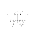
バッテリモジュール20は、図2に示すように、ブロック状の電池ケース21を有している。電池ケース21内には、複数の二次電池31からなる組電池30や制御基板28が収容されている(図3参照)。なお、以下の説明において、図2及び図3を参照する場合、電池ケース21が設置面に対して傾きなく水平に置かれた時の電池ケース21の上下方向をY方向とし、電池ケース21の長辺方向に沿う方向をX方向とし、電池ケース21の奥行き方向をZ方向として説明する。
As shown in FIG. 2, the
電池ケース21は、図3に示すように、上方に開口する箱型のケース本体23と、複数の二次電池31を位置決めする位置決め部材24と、ケース本体23の上部に装着される中蓋25と、中蓋25の上部に装着される上蓋26と、を備える。ケース本体23内には、各二次電池31が個別に収容される複数のセル室23AがX方向に並んで設けられている。
As shown in FIG. 3, the
位置決め部材24の上面には、図3に示すように、複数のバスバー27が配置されている。位置決め部材24がケース本体23内に配置された複数の二次電池31の上部に配置されることで、複数の二次電池31が位置決めされると共に複数のバスバー27によって直列に接続されるようになっている。
As shown in FIG. 3, a plurality of
中蓋25は、図3に示すように、平面視略矩形状をなし、Y方向に高低差を付けた形状とされている。中蓋25のX方向両端部には、図示しないハーネス端子が接続される一対の端子部22P,22Nが設けられている。一対の端子部22P,22Nは、例えば、鉛合金等の金属からなり、端子部22Pが正極側端子部、端子部22Nが負極側端子部である。
As shown in FIG. 3, the
また、中蓋25は、図3に示すように、制御基板28が内部に収容可能とされており、中蓋25がケース本体23に装着されることで、二次電池31と制御基板28とが接続されるようになっている。
Further, as shown in FIG. 3, the
次に図4を参照して、蓄電システム10の電気的構成を説明する。図4に示すように、バッテリモジュール20及び車両発電機15は、自動車1に搭載された電気負荷11及び車両ECU14に対して電源ライン36P、グランドライン36Nを介して接続されている。電気負荷11としては、セルモータ等のエンジン始動装置、ヘッドライド、車内灯、オーディオ、時計、セキュリティ装置などを例示することができる。
Next, the electrical configuration of the
これら電気負荷11は、バッテリモジュール20及び車両発電機15(オルタネータ)と接続されており、バッテリモジュール20及び車両発電機15から電力供給される。すなわち、駐車中や停車中など、車両発電機15が発電していない時は、バッテリモジュール20から電力が供給される。また、例えば、走行中で、負荷を発電量が上回っている時は、車両発電機15から電力が供給され、その余剰の電力によりバッテリモジュール20は充電される。また、負荷を発電量が下回っている時は、その不足分を補うため、車両発電機15だけでなく、バッテリモジュール20からも電力が供給される。
These electric loads 11 are connected to the
車両ECU14(Electronic Control Unit)は、自動車1に搭載された各機器の制御を行うものとされる。車両発電機15は、図示しない充電回路を備えており、車両ECU14は、充電回路を介して、車両発電機15からバッテリモジュール20に供給される電力の制御を行う構成となっている。
The vehicle ECU 14 (Electronic Control Unit) controls each device mounted on the automobile 1. The
バッテリモジュール20は、組電池30と、電流センサ41と、サーミスタ43と、電流遮断装置45と、組電池30を管理する電池管理装置50(以下、BMU50)と、を備える。組電池30は、直列に接続された複数の二次電池31(蓄電素子)から構成されている。なお、BMU50は、蓄電素子管理装置の一例である。
The
組電池30、電流センサ41、電流遮断装置45は、接続ライン35を介して、直列に接続されている。本実施形態では、電流センサ41を負極側、電流遮断装置45を正極側に配置しており、電流センサ41は負極側端子部22N、電流遮断装置45は、正極側端子部22Pにそれぞれ接続されている。
The assembled
電流センサ41は、電池ケース21の内部に設けられており、二次電池31に流れる電流を検出する機能を果たす。サーミスタ43は接触式あるいは非接触式で、二次電池31の温度[℃]を測定する機能を果たす。
The
電流センサ41とサーミスタ43は、信号線によって、BMU50に電気的に接続されており、電流センサ41やサーミスタ43の検出値は、BMU50に取り込まれる構成になっている。電流センサ41は、電池ケース21内に設けられている。
The
電流遮断装置45は、電池ケース21の内部に設けられている。電流遮断装置45は、例えば、FET等の半導体スイッチやリレーであり、BMU50からの指令(制御信号)に応答して、正極側の電力ラインを開放することで、二次電池31の電流を遮断する機能を果たす。
The current interrupt
BMU50は、電圧検出回路60と、放電回路65と、中央処理装置であるCPU71(制御部)と、メモリ73(記憶部)と、通信部75と、計時部76と、を備えている。上述した制御基板28は、電圧検出回路60、CPU71、メモリ73などを主に構成するものとされる。また、図4に示すように、BMU50の電源ラインは組電池30の正極側の接続点J1に接続され、グランドラインは負極側の接続点J2に接続されており、BMU50は組電池30から電力の供給を受ける。
The
電圧検出回路60は、検出ラインを介して、各二次電池31の両端にそれぞれ接続され、CPU71からの指示に応答して、各二次電池31の電圧及び組電池30の総電圧を測定する機能を果たす。放電回路65は、図5に示すように、放電抵抗Rと放電スイッチSWとを備え、二次電池31に対して並列に接続されている。CPU71から指令を与えて、放電スイッチSWをオンすることで二次電池31を個別に放電することができ、二次電池31の充電量差を少なくする処理(均等化処理)を行うことができる。
The
CPU71は、電流センサ41、電圧検出回路60、サーミスタ43の出力から、二次電池31の電流、電圧、温度を監視しており、異常を検出した場合には、電流遮断装置45を作動して二次電池31が危険な状態になることを防いでいる。
The
また、メモリ73は、例えばフラッシュメモリやEEPROM等の不揮発性メモリである。メモリ73には、二次電池31を管理するためのプログラムや、プログラムの実行に必要なデータが記憶されている。また、メモリ73には、二次電池31間の充電量差を推定する充電量差推定処理(後述)を行うためのプログラムや、二次電池31の充電電圧を決定する充電電圧決定処理(後述)を行うためのプログラムや、充電電圧決定処理を行うために用いる電圧決定用データ(後述)が記憶されている。通信部75は、車両ECU14と通信線17を介して接続されている。これにより、BMU50は、車両ECU14との間で通信可能となっている。計時部76は、現在時刻を計時するものとされる。
The
二次電池31は、例えば、正極活物質にリン酸鉄リチウム(LiFePO4)、負極活物質にグラファイトを用いたリン酸鉄系のリチウムイオン二次電池とされる。図6に二次電池31のSOC−OCV相関特性を示す。二次電池31は、図6に示すように、SOCの変化量に対するOCVの変化量が相対的に低い低変化領域と、相対的に高い高変化領域とを有している。
The
具体的には、二次電池31は、図6に示すように、SOCが10%未満である充電初期(放電末期)、及びSOCが90%以上である充電末期においてSOCの増加に対してOCV(開放電圧)が急激に上昇する領域(高変化領域)を有する。また、二次電池31は、SOCが10%以上90%未満である充電中期(放電中期)においてSOCの増加に対してOCVが略一定である領域(低変化領域、プラトー領域)を有する。
Specifically, as shown in FIG. 6, the
複数の二次電池31において充電量差があると、充電末期に相対的に充電量の大きい二次電池31が過電圧となり、劣化する可能性がある。そこで、本実施形態のCPU71は、複数の二次電池31間の充電量差に基づいて、複数の二次電池31の充電電圧を決定する充電電圧決定処理(決定処理)を行う。
If there is a charge amount difference among the plurality of
2.電圧決定用データ
CPU71は、複数の二次電池31間の充電量差、及び電圧決定用データ(図7参照)に基づいて充電電圧を決定する。電圧決定用データは、図7に示すように、複数の二次電池31について、充電量差と充電電圧とを対応付けたデータであり、メモリ73に記憶されている。電圧決定用データは、複数の二次電池31(組電池30)に対して試験的に充電を行った結果に基づいて作成される。
2. Voltage determination data The
電圧決定用データを作成するためには、組電池30に対して充電量差及び充電電圧をそれぞれ変えて試験的に充電を行い、二次電池31の各電圧が、規定の電圧(例えば4V)に達するか否かを調べる。その試験結果を図8に示す。なお、以下の説明では、組電池30が4つの二次電池31を備え、4つの二次電池31のうち、1つの二次電池31の充電量が相対的に高く、残りの3つの二次電池31の充電量がほぼ等しい値で相対的に低い場合を例示する。なお、4つの二次電池31の充電量がこのような関係を有する場合には、充電末期において充電量が高い1つの二次電池31の電圧が、相対的に充電量が低い他の3つの二次電池31の電圧に比べて高くなり、過電圧になる。また、以下の説明では「充電量差」とは、4つの二次電池31のうち、最も充電量が高い二次電池31と、最も充電量が低い二次電池31の充電量の差のことを言うものとする。
In order to create the voltage determination data, the assembled
図8においては、複数の二次電池31の各電圧のうち、いずれかの電圧が規定の電圧に達したものを網掛けの欄で図示してあり、規定の電圧に達しなかったものを空欄で図示してある。なお、本実施形態では、規定の電圧を例えば4Vとし、二次電池31の電圧が4Vを超えた状態を過電圧であると判定しているが、規定の電圧は4Vに限定されず適宜変更可能である。また、図8では、充電量差を例えば0〜800mAhの範囲内で設定し、充電電圧を14.4〜14.8Vの範囲内で設定した場合の結果を図示しているが、この数値範囲に限定されるものではない。なお、上記充電量差の範囲(0〜800mAh)は、二次電池31の定格容量が70Ahである場合の値であり、定格容量の0〜1.14%に相当する。また、二次電池31の定格容量はこれに限定されない。例えば、二次電池31の定格容量が35Ahである場合には、充電量差の範囲は0〜400mAh(定格容量の0〜1.14%に相当)となる。
In FIG. 8, among the voltages of the plurality of
図8に示す充電量差と充電電圧の組み合わせ(図8では計50種類)のうち、3種類の組み合わせにおける試験結果をそれぞれ図9から図11に示す。なお、本実施形態では、いずれも定電圧充電時の試験結果を用いて電圧決定用データを作成する。なお、定電圧充電では、組電池30の電圧が所定の充電電圧に到達した以降は、その充電電圧を維持しつつ、時間経過に伴って充電電流が垂下していく。図9では、充電量差が700mAh、充電電圧が14.4Vの条件で充電した場合の試験結果を示している。図9によれば、時間経過に伴って充電電流が垂下する過程で、相対的に充電量の高い1つの二次電池31の電圧(符号31Hを付す)が大きくなり、他の3つの二次電池31の電圧(符号31Lを付す)がわずかに小さくなるものの、電圧31Hが4Vを超えることがない。つまり、この充電量差と充電電圧の組み合わせは、図8において空欄で図示される。
FIG. 9 to FIG. 11 show test results for three types of combinations of the charge amount difference and charge voltage shown in FIG. 8 (total of 50 types in FIG. 8). Note that in this embodiment, voltage determination data is created using test results during constant voltage charging. In the constant voltage charging, after the voltage of the assembled
また、充電量差が300mAh、充電電圧が14.6Vで設定されている場合の試験結果を図10に示し、充電量差が250mAh、充電電圧が14.8Vで設定されている場合の試験結果を図11に示す。図10及び図11の試験結果によれば、図10及び図11で例示する充電量差と充電電圧の組み合わせでは、いずれも二次電池31の電圧が4Vを超えないことから、図8においていずれも空欄で図示されている。なお、図10〜図12では、図9と同様に、相対的に充電量の高い1つの二次電池31の電圧に符号31Hを付し、相対的に充電量の低い3つの二次電池31の電圧に符号31Lを付している。
FIG. 10 shows a test result when the charge amount difference is set at 300 mAh and the charge voltage is 14.6V, and the test result when the charge amount difference is set at 250 mAh and the charge voltage is set at 14.8V. Is shown in FIG. According to the test results of FIGS. 10 and 11, in any combination of the charge amount difference and the charge voltage illustrated in FIGS. 10 and 11, the voltage of the
図8に示す試験結果から、図7に示す電圧決定用データを作成する際には、例えば次のようにする。図8に示すように、充電量差が0〜250mAhの範囲では、充電電圧が14.4V〜14.8Vのいずれの値であっても、二次電池31の電圧が4Vを超えることがないから、図7に示すように、充電電圧を最も高い値である14.8Vとする。また、充電量差が250〜300mAhの範囲では、充電電圧が14.4V〜14.6Vのいずれの値であっても、二次電池31の電圧が4Vを超えることがないから、充電電圧を14.6Vとする。そして、充電量差が300〜800mAhの範囲では、充電電圧が14.5V以上になると二次電池31の電圧が4Vを超える場合があるため、充電電圧を14.4Vとする。つまり、図7に示す充電電圧は、ある充電量差において二次電池31が過電圧にならない(4Vを超えない)充電電圧のうち、最も高い電圧のことである。
When the voltage determination data shown in FIG. 7 is created from the test results shown in FIG. 8, for example, the following is performed. As shown in FIG. 8, when the charge amount difference is in the range of 0 to 250 mAh, the voltage of the
また、図12には、充電量差が20000mAh、充電電圧が14.0Vで設定された場合の定電圧充電の試験結果を示す。図12に示すように、充電電圧14.0Vであれば、充電量差が800mAhよりも十分大きい場合であっても、二次電池31の各電圧が4Vを超えることがない。この結果に基づいて、充電量差が800mAhより大きい場合には、充電電圧を例えば14.0Vとする(図7参照)。なお、本実施形態の電圧決定用データでは、図7に示すように、充電量差の範囲を4つに分け、各範囲について充電電圧をそれぞれ設定した場合を例示したが、充電量差の範囲の分け方はこれに限定されず適宜変更可能である。
FIG. 12 shows the test results of constant voltage charging when the charge amount difference is set to 20000 mAh and the charging voltage is set to 14.0V. As shown in FIG. 12, when the charging voltage is 14.0V, each voltage of the
3.充電電圧の決定に係るCPUの処理
次に充電電圧の決定に係るCPU71の処理について説明する。本実施形態では、複数の二次電池31間の充電量差を推定し、推定した充電量差と、上述した電圧決定用データに基づいて充電電圧を決定する。充電電圧の決定に係るCPU71の処理は、図13に示すように、S110〜S130のステップから構成されている。
3. Processing of CPU related to determination of charging voltage Next, processing of the
<充電量差推定処理(推定処理)>
本実施形態では、充電量差推定処理として、放電回路65が動作していない時間(非動作時間)に基づいて、複数の二次電池31間の充電量差を推定する処理を例示する。本実施形態では、CPU71は、各二次電池31の電圧の差が所定値以上になると、放電回路65を動作させ、相対的に充電量が多い(電圧が高い)二次電池31を放電することで、二次電池31間の充電量差を少なくする均等化処理を行う。プラトー領域においては、各二次電池31の電圧の差が小さいことから、放電回路65は動作せず、各二次電池31の電圧の差が大きくなる満充電付近において、放電回路65が動作する。
<Charging amount difference estimation process (estimation process)>
In the present embodiment, as the charge amount difference estimation process, a process of estimating a charge amount difference among the plurality of
均等化処理が完了した時点では、複数の二次電池31の充電量は、ほぼ等しいものとなっているが、その後、放電回路65が動作していない状態が続くことで、各二次電池31の充電量は、それぞれ自己放電によって減少する。この時、各二次電池31の自己放電容量(ひいては自己放電電流)のばらつきに起因して充電量差が生じる。そして、放電回路65が動作していない期間が長い程、自己放電に起因した充電量差は大きくなる。このため、放電回路65が動作していない時間(均等化処理が実行されていない時間)を求めることで、複数の二次電池31間の充電量差を推定することができる。
At the time when the equalization process is completed, the charge amounts of the plurality of
具体的には、CPU71は、放電回路65が停止した際に、その時刻T1を計時部76から取得し、メモリ73に記憶する。充電量差推定処理を行う際には、CPU71は、現在時刻T2と、その直前に放電回路65が停止した時刻T1との時間差DTを算出する。つまり、時間差DTは、放電回路65が動作していない時間(前回均等化処理が完了してからの経過時間)である。
Specifically, when the
続いて、CPU71は、メモリ73に記憶されている各二次電池31の自己放電電流[mA]の値に、時間差DTを乗算することで、放電回路65の非動作時間(時間差DT)における各二次電池31の自己放電容量[mAh]をそれぞれ算出する。次に、CPU71は、算出された各二次電池31の自己放電容量のうち、例えば、最も大きい自己放電容量と、最も小さい自己放電容量の差を算出することで充電量差を推定する(S110)。なお、CPU71は、二次電池31間の自己放電電流の差と、時間差DTとを乗算することで、充電量差を推定してもよい。また、各二次電池31の自己放電電流の値は、例えば、二次電池31の製造時などに測定したものを、メモリ73に予め記憶しておけばよい。
Subsequently, the
<充電電圧決定処理(決定処理)>
次に、CPU71は、充電量差推定処理によって推定した複数の二次電池31の充電量差と、メモリ73に記憶されている電圧決定用データ(図7参照)に基づいて、組電池30の充電電圧V1を決定する(S120)。例えば、充電量差が、200mAhである場合には、図7に基づいて、充電電圧V1は、14.8Vと決定され、充電量差が500mAhである場合には、充電電圧V1は、14.4Vと決定される。図7に示すように、充電電圧V1は、充電量差が、所定範囲(例えば、0〜800mAh)内にある場合には、充電量差が大きい程小さい値で設定され、所定範囲以上(例えば、800mAh以上)である場合には、充電量差に関わらず一定の電圧(図7では14.0V)で決定される。このように、本実施形態では、図7の電圧決定用データを用いて充電電圧を決定することで、二次電池31が過電圧にならない(4Vを超えない)充電電圧のうち、最も高い電圧を充電電圧V1として決定することができる。
<Charging voltage determination process (decision process)>
Next, the
そして、CPU71は、充電電圧決定処理で決定した充電電圧V1の値(指令値)を、通信部75を介して車両ECU14に送信する(S130)。車両ECU14は、例えば、車両発電機15に設けられた充電回路(例えば電圧レギュレータ)を動作させることで、車両発電機15の出力電圧(組電池30に印加される充電電圧)がBMU50から送信された充電電圧V1となるように制御を行う。
Then, the
次に、本実施形態の効果について説明する。本実施形態では、複数の二次電池31間の充電量差に基づいて充電電圧を決定することで二次電池31が過電圧となる事態を抑制することができる。具体的には、充電量差が大きい場合には、充電電圧は、より小さい値で設定されるから、二次電池31が過電圧となる事態を抑制することができる。また、充電量差が小さい場合には、充電電圧は、より大きい値で設定されるから、充電可能な充電量を多くすることができる。
Next, the effect of this embodiment will be described. In this embodiment, the situation where the
また、本実施形態では、充電量差と充電電圧とを対応付けた電圧決定用データが記憶されたメモリ73を備えており、CPU71は、充電量差と電圧決定用データに基づいて、充電電圧を決定する。メモリ73に記憶されている電圧決定用データに基づいて充電電圧を決定することで、例えば充電電圧を計算によって求める処理を行う場合と比べて、容易に充電電圧を決定することができる。
Further, in the present embodiment, a
また、CPU71は、充電量差を推定する充電量差推定処理を実行する。これにより、充電電圧を決定する時点の二次電池31の状態に基づいた充電量差を推定することができ、例えば予め記憶された充電量差を用いる場合と比べて、より正確な充電量差によって充電電圧を決定することができる。
Moreover, CPU71 performs the charge amount difference estimation process which estimates a charge amount difference. Thereby, the charge amount difference based on the state of the
また、複数の二次電池31間の充電量差を小さくする均等化処理を行う放電回路65を備え、充電量差推定処理は、前回均等化処理が完了してからの経過時間に基づいて充電量差を推定する処理とされる。
Moreover, the
複数の二次電池31に対する均等化処理が完了した時点から次回の均等化処理が開始されるまでの間(放電回路65の非動作時間)には、各二次電池31の自己放電容量の差に起因して複数の二次電池31間の充電量差が生じる。自己放電によって生じる充電量差は、前回の均等化処理が完了してからの経過時間が長い程、大きくなる。このため、CPU71は、前回均等化処理が完了してからの経過時間に基づいて充電量差を推定することができる。
The difference between the self-discharge capacities of the
また、二次電池31は、例えば、リン酸鉄系のリチウムイオン電池とされる。リン酸鉄系のリチウムイオン電池では、満充電付近(充電終了付近)で急激に電圧が上昇する特性があるため、放電回路65による均等化処理が間に合わず、二次電池31が過電圧となる事態が懸念される。本実施形態では、充電量差に基づいて、過電圧にならない充電電圧を予め決定するため、リチウムイオン電池のような充電終了付近で急激に電圧が上昇する特性を有する電池であっても、過電圧を防止することができる。
The
<他の実施形態>
本明細書で開示される技術は上記記述及び図面によって説明した実施形態に限定されるものではなく、例えば次のような種々の態様も含まれる。
<Other embodiments>
The technology disclosed in the present specification is not limited to the embodiments described with reference to the above description and drawings, and includes, for example, the following various aspects.
(1)上記実施形態では、蓄電素子の一例としてリン酸鉄系の正極活物質を使用したリチウムイオン二次電池を示したが、これに限定されない。蓄電素子としては、リチウムイオン二次電池以外の二次電池や、電気化学現象を伴うキャパシタ等でもよい。なお、リチウムイオン二次電池の正極活物質は、リン酸鉄系に限定されず、適宜変更可能であり、例えば、三元系の正極活物質を使用してもよい。なお、三元系のようにSOCに対してOCVが一義的に定まる特性(SOCの変化量に対するOCVの変化量が大きい特性)を有する二次電池31を用いる場合には、リン酸鉄系に比べて、各二次電池31のOCVからSOCを容易に推定することができる。このような場合には、各二次電池31のOCVを測定することで、SOCを推定し、SOCから二次電池31の充電量差を推定してもよい。また、各二次電池31のSOC差と充電電圧とを対応付けた電圧決定用データを用いて、SOC差から充電電圧を直接的に決定してもよい。なお、各二次電池31のSOCの推定方法は、OCVから求める方法(OCV法)に限定されず、例えば、電流積算法などを用いてもよい。
(1) In the above embodiment, a lithium ion secondary battery using an iron phosphate-based positive electrode active material is shown as an example of a storage element, but the present invention is not limited to this. The power storage element may be a secondary battery other than a lithium ion secondary battery, a capacitor with an electrochemical phenomenon, or the like. In addition, the positive electrode active material of a lithium ion secondary battery is not limited to an iron phosphate type | system | group, It can change suitably, For example, you may use a ternary type positive electrode active material. In addition, when using the
(2)上記実施形態では、制御部としてCPU71を例示したが、これに限定されない。制御部は、複数のCPUを備える構成や、ASIC(Application Specific Integrated Circuit)などのハード回路であってもよく、FPGA、MPU、また、それらが組み合わされた構成であってもよい。つまり、制御部は、上記実施形態で例示した各処理を、ソフトウェア又はハード回路を利用して実行するものであればよい。
(2) In the above embodiment, the
(3)上記実施形態では、バッテリモジュール20が搭載される車両として自動車1を例示したが、これに限定されない。本明細書で開示される技術は、電車など自動車以外の車両に適用することも可能である。また、上記実施形態では、充電器として、車両に搭載されているもの(車両発電機15)を例示したが、充電器は、車両の外部に設置されているものであってもよい。例えば、本明細書で開示される技術を電車に適用した場合には、充電器は駅などに設置されていてもよい。また、電車に搭載された二次電池が架線から供給される電力によって充電される構成であってもよい。また、バッテリモジュール20は、車両に搭載されるものに限定されず、産業用の電源装置(非常用電源など)として広く用いることができる。
(3) In the said embodiment, although the motor vehicle 1 was illustrated as a vehicle by which the
(4)上記実施形態では、組電池30が4つの二次電池31を備える構成を例示したが、これに限定されない。二次電池31の個数は2つ以上であればよく、その個数は適宜変更可能である。
(4) In the said embodiment, although the assembled
(5)上記実施形態では、4つの二次電池31のうち、1つの二次電池31の充電量が相対的に高く、他の3つの二次電池31の充電量が相対的に低い場合を例示したが、これに限定されない。例えば、2つの二次電池31の充電量が相対的に高く、他の2つの二次電池31の充電量が相対的に低い場合の試験結果(図14参照)に基づいた電圧決定用データや、3つの二次電池31の充電量が相対的に高く、残りの1つの二次電池31の充電量が相対的に低い場合の試験結果(図15参照)に基づいた電圧決定用データなど、様々なパターンに対応した電圧決定用データがメモリ73に記憶されていてもよい。このようにすれば、CPU71は、充電電圧決定処理において、数種類の電圧決定用データのうち、該当する充電量差のパターンに対応する電圧決定用データを使用して充電電圧を決定することができる。
(5) In the above embodiment, the case where the charge amount of one
また、複数の二次電池31の各充電量が全て異なる場合であっても、本明細書で開示される技術は適用可能である。なお、電圧決定用データを作成する際には、充電量が最も高い二次電池31と、充電量が最も低い二次電池31の充電量差に基づいて、電圧決定用データを作成することが好ましいが、これに限定されない。
Moreover, even if it is a case where each charge amount of the some
(6)本明細書で開示される技術は、定電圧充電の場合に限定されず、例えば、車両減速時における回生充電について適用することも可能である。回生充電時における二次電池31の電流及び電圧の時間推移の一例を図16に示す。図16に示すように、回生充電では、例えば、定電流充電時に電流が短時間で急激に上昇し、各二次電池31の電圧がそれぞれ上昇する。この時、相対的に充電量が高い二次電池31の電圧(符号31H1)は、充電量が低い二次電池31の電圧(符号31L1)に比して上昇量が大きく、過電圧となる事態が懸念される。本明細書で開示される技術を回生充電に適用する場合には、上述した回生充電時の状況と同じ状況で試験的な充電を予め行い、その試験結果に基づいて電圧決定用データを作成し、この電圧決定用データを用いて充電電圧を決定すればよい。
(6) The technology disclosed in the present specification is not limited to the case of constant voltage charging, and can be applied to, for example, regenerative charging during vehicle deceleration. An example of the time transition of the current and voltage of the
(7)上記実施形態では、充電電圧決定処理をBMU50側で行い、充電器(車両発電機15)の制御を車両ECU14側で行う構成を例示したが、これに限定されない。充電電圧決定処理及び、充電器の制御を一つの制御部で行う構成としてもよい。
(7) In the above embodiment, the configuration in which the charging voltage determination process is performed on the
(8)上記実施形態では、均等化処理として、相対的に充電量が多い二次電池31を放電する処理を例示したが、これに限定されない。例えば、相対的に充電量が少ない二次電池31を充電することで複数の二次電池31の充電量差を少なくしてもよい。
(8) In the said embodiment, although the process which discharges the
(9)上記実施形態では、充電量差推定処理によって推定された充電量差に基づいて、充電電圧を決定する技術を例示したが、これに限定されない。例えば、複数の二次電池31の製造時などに測定した各二次電池31の初期容量をメモリ73に記憶しておき、この初期容量の差を充電量差として充電電圧決定処理を行ってもよい。
(9) In the above embodiment, the technique for determining the charge voltage based on the charge amount difference estimated by the charge amount difference estimation process is exemplified, but the present invention is not limited to this. For example, the initial capacity of each
(10)上記実施形態では、充電量差推定処理として放電回路65の非動作時間を用いて充電量差を推定するものを例示したが、これに限定されない。充電量差推定処理としては、二次電池31について電圧と充電量の相関関係を示すデータを予めメモリ73に記憶させておき、そのデータと、充電中に計測した各二次電池31間の電圧差に基づいて充電量差を推定し、その充電量差から充電電圧を決定してもよい。また、各二次電池31間の電圧差から直接的に充電電圧を決定してもよい。具体的には、充電量差を用いる場合と同様に各二次電池31間の電圧差と充電電圧とを対応付けた電圧決定用データをメモリ73に記憶させておき、その電圧決定用データと電圧差に基づいて充電電圧を決定すればよい。
(10) In the above embodiment, the charge amount difference estimation process is exemplified by estimating the charge amount difference using the non-operation time of the
(11)上記実施形態では、充電量差推定処理において、メモリ73に記憶されている二次電池31の自己放電電流の値を用いて充電量差を推定する処理を例示したが、これに限定されない。例えば、放電回路65の動作時間に基づいて二次電池31間の自己放電電流の差を算出し、これに基づいて充電量差を推定してもよい。例えば、一つの二次電池31についてのみ放電回路65が動作する場合、その二次電池31(以下、符号31A)は、他の二次電池31(以下、符号31B)に比べて充電量が高いことになる。言い換えると、二次電池31Aは、放電回路65の非動作時間(上記実施形態における時間差DTに対応)における自己放電容量(ひいては自己放電電流)の値が相対的に小さいものであると考えることができる。
(11) In the above embodiment, in the charge amount difference estimation process, the process of estimating the charge amount difference using the value of the self-discharge current of the
このような場合、CPU71は、放電回路65による二次電池31Aの放電電流を、その放電回路65の動作時間(放電回路65による放電時間)について積算することで、他の二次電池31との自己放電容量の差DXを算出する。この差DXは、直前の放電回路65の非動作時間における自己放電によって生じたものであると考えることができる。このため、自己放電容量の差DXを、直前の放電回路65の非動作時間で割ることで、二次電池31Aと他の二次電池31Bとの自己放電電流の差DIを算出することができる。自己放電電流の差DIを算出し、これをメモリ73に記憶させておけば、これ以降は、自己放電電流の差DIに放電回路65の非動作時間を乗算することで、二次電池31Aと他の二次電池31Bとの充電量差を推定することができ、この充電量差に基づいて最適な充電電圧を決定することができる。
In such a case, the
(12)上記実施形態では、各二次電池31の自己放電電流のばらつきに起因して充電量差が生じる場合を例示したが、充電量差が生じる原因は、これに限定されない。例えば、各二次電池31の電圧を検出するための各IC(電圧検出回路60の構成部品)の消費電流のばらつきに起因して、充電量差が生じる場合がある。このような場合には、例えば、各二次電池31の自己放電電流に対して、対応する各ICの消費電流を加算することで各二次電池31の放電電流を求め、この放電電流の差と、放電回路65の非動作時間とを乗算することで、二次電池31の充電量差を求めることができる。
(12) In the above embodiment, the case where the charge amount difference occurs due to the variation in the self-discharge current of each
10:蓄電システム
15:車両発電機(充電器の一例)
20:バッテリモジュール(蓄電装置の一例)
31:二次電池(蓄電素子の一例)
50:BMU(蓄電素子管理装置の一例)
65:放電回路(均等化回路の一例)
71:CPU(制御部の一例)
73:メモリ(記憶部の一例)
DT:時間差(前回均等化処理が完了してからの経過時間)
10: Power storage system 15: Vehicle generator (an example of a charger)
20: Battery module (an example of a power storage device)
31: Secondary battery (an example of a storage element)
50: BMU (an example of a storage element management device)
65: Discharge circuit (an example of an equalization circuit)
71: CPU (an example of a control unit)
73: Memory (an example of a storage unit)
DT: Time difference (elapsed time since the previous equalization process was completed)
Claims (9)
前記制御部は、
前記複数の蓄電素子間の充電量差又は電圧差に基づいて、前記充電電圧を決定する決定処理を実行する蓄電素子管理装置。 A storage element management device including a control unit that determines charging voltages for a plurality of storage elements connected in series,
The controller is
An electricity storage element management apparatus that executes a determination process for determining the charging voltage based on a charge amount difference or a voltage difference between the plurality of electricity storage elements.
前記充電電圧は、前記充電量差又は前記電圧差が大きい程小さい値で設定される蓄電素子管理装置。 It is an electrical storage element management apparatus of Claim 1, Comprising:
The charge element is a storage element management device that is set to a smaller value as the charge amount difference or the voltage difference is larger.
前記充電量差又は前記電圧差のうちいずれか一方と前記充電電圧とを対応付けた電圧決定用データが記憶された記憶部を備える蓄電素子管理装置。 The storage element management device according to claim 1 or 2,
A storage element management device comprising a storage unit storing voltage determination data in which one of the charge amount difference or the voltage difference is associated with the charge voltage.
前記制御部は、
前記充電量差又は前記電圧差のうちいずれか一方と、前記記憶部に記憶された前記電圧決定用データに基づいて、前記充電電圧を決定する蓄電素子管理装置。 It is an electrical storage element management apparatus of Claim 3, Comprising:
The controller is
A storage element management device that determines the charge voltage based on either the charge amount difference or the voltage difference and the voltage determination data stored in the storage unit.
前記制御部は、
前記充電量差を推定する推定処理を実行する蓄電素子管理装置。 It is an electrical storage element management apparatus as described in any one of Claims 1-4,
The controller is
A storage element management device that executes an estimation process for estimating the charge amount difference.
前記複数の蓄電素子間の充電量差を小さくする均等化処理を行う均等化回路を備え、
前記推定処理は、
前回前記均等化処理が完了してからの経過時間に基づいて、前記決定処理に用いる前記充電量差を推定する処理である蓄電素子管理装置。 The storage element management device according to claim 5,
An equalization circuit for performing an equalization process for reducing a charge amount difference between the plurality of power storage elements;
The estimation process includes
A storage element management device, which is a process of estimating the charge amount difference used for the determination process based on an elapsed time since the previous equalization process was completed.
前記蓄電素子は、リン酸鉄系のリチウムイオン電池である蓄電素子管理装置。 It is an electrical storage element management apparatus as described in any one of Claims 1-6,
The storage element management device is an iron phosphate lithium ion battery.
前記複数の蓄電素子と、を備える蓄電装置。 The storage element management device according to any one of claims 1 to 7,
A power storage device comprising the plurality of power storage elements.
前記複数の蓄電素子に対して充電を行う充電器と、を備える蓄電システム。 The power storage device according to claim 8,
A power storage system comprising: a charger that charges the plurality of power storage elements.
Priority Applications (4)
| Application Number | Priority Date | Filing Date | Title |
|---|---|---|---|
| JP2016071469A JP6759668B2 (en) | 2016-03-31 | 2016-03-31 | Power storage element management device, power storage device, and power storage system |
| CN201710171915.2A CN107276140B (en) | 2016-03-31 | 2017-03-21 | Power storage element management device, power storage device, and power storage system |
| US15/466,790 US10476280B2 (en) | 2016-03-31 | 2017-03-22 | Energy storage management device deciding charge voltage based on difference in charge amount or voltage difference between energy storage devices |
| DE102017205529.4A DE102017205529A1 (en) | 2016-03-31 | 2017-03-31 | Management device for energy storage devices, energy storage device and energy storage system |
Applications Claiming Priority (1)
| Application Number | Priority Date | Filing Date | Title |
|---|---|---|---|
| JP2016071469A JP6759668B2 (en) | 2016-03-31 | 2016-03-31 | Power storage element management device, power storage device, and power storage system |
Publications (2)
| Publication Number | Publication Date |
|---|---|
| JP2017184534A true JP2017184534A (en) | 2017-10-05 |
| JP6759668B2 JP6759668B2 (en) | 2020-09-23 |
Family
ID=59885440
Family Applications (1)
| Application Number | Title | Priority Date | Filing Date |
|---|---|---|---|
| JP2016071469A Active JP6759668B2 (en) | 2016-03-31 | 2016-03-31 | Power storage element management device, power storage device, and power storage system |
Country Status (4)
| Country | Link |
|---|---|
| US (1) | US10476280B2 (en) |
| JP (1) | JP6759668B2 (en) |
| CN (1) | CN107276140B (en) |
| DE (1) | DE102017205529A1 (en) |
Cited By (4)
| Publication number | Priority date | Publication date | Assignee | Title |
|---|---|---|---|---|
| JP2019187027A (en) * | 2018-04-05 | 2019-10-24 | 株式会社デンソー | Power storage device |
| DE112020001521T5 (en) | 2019-03-27 | 2021-12-16 | Gs Yuasa International Ltd. | Energy storage device, capacity estimation method for energy storage device, and capacity estimation program for energy storage device |
| WO2022186061A1 (en) * | 2021-03-01 | 2022-09-09 | 株式会社Gsユアサ | Control device of power storage cell, power storage device, electricity charging system, control method for electricity charging voltage |
| WO2022196362A1 (en) * | 2021-03-18 | 2022-09-22 | 株式会社Gsユアサ | Power storage device and control method for power storage device |
Families Citing this family (5)
| Publication number | Priority date | Publication date | Assignee | Title |
|---|---|---|---|---|
| WO2018129516A2 (en) * | 2017-01-09 | 2018-07-12 | Milwaukee Electric Tool Corporation | Battery pack |
| JP7056513B2 (en) * | 2018-10-26 | 2022-04-19 | トヨタ自動車株式会社 | Battery control device |
| JP7302470B2 (en) * | 2019-12-27 | 2023-07-04 | マツダ株式会社 | Lithium-ion battery device for vehicles |
| JP7191873B2 (en) * | 2020-01-17 | 2022-12-19 | 株式会社東芝 | Charge/discharge control device, charge/discharge system, charge/discharge control method, and charge/discharge control program |
| CN116250110A (en) * | 2021-02-09 | 2023-06-09 | 宁德时代新能源科技股份有限公司 | Battery charging method, controller, battery management system, battery and power utilization device |
Citations (11)
| Publication number | Priority date | Publication date | Assignee | Title |
|---|---|---|---|---|
| JPS5185437A (en) * | 1975-01-22 | 1976-07-27 | Yuasa Battery Co Ltd | |
| JP2000133318A (en) * | 1998-08-21 | 2000-05-12 | Sony Corp | Battery pack |
| JP2001526877A (en) * | 1997-05-15 | 2001-12-18 | エンレブ コーポレイション | Battery and battery equalization method connected in series |
| JP2007018871A (en) * | 2005-07-07 | 2007-01-25 | Toyota Motor Corp | Control device of secondary battery and system carrying this device |
| JP2009044946A (en) * | 2007-07-13 | 2009-02-26 | Sanyo Electric Co Ltd | Method for charging battery pack |
| WO2009025307A1 (en) * | 2007-08-22 | 2009-02-26 | Gs Yuasa Corporation | Aircraft and method of using aircraft |
| JP2011004509A (en) * | 2009-06-18 | 2011-01-06 | Panasonic Corp | Charge control circuit, battery pack, and charging system |
| JP2011041452A (en) * | 2009-07-17 | 2011-02-24 | Toshiba Corp | Assembled battery unit and vehicle |
| US20110156647A1 (en) * | 2009-12-28 | 2011-06-30 | Jin-Hong An | Apparatus and method for charging a battery pack |
| JP2014217169A (en) * | 2013-04-25 | 2014-11-17 | 株式会社Gsユアサ | Electrical power storage device |
| WO2015166908A1 (en) * | 2014-04-30 | 2015-11-05 | 日立工機株式会社 | Cell pack, charging device, and electric tool |
Family Cites Families (11)
| Publication number | Priority date | Publication date | Assignee | Title |
|---|---|---|---|---|
| JP3419115B2 (en) | 1994-11-11 | 2003-06-23 | 日産自動車株式会社 | Battery charge / discharge protection device |
| JP3635760B2 (en) | 1996-01-17 | 2005-04-06 | 日産自動車株式会社 | Charge control device for battery pack |
| JP3620517B2 (en) | 2002-06-12 | 2005-02-16 | 日産自動車株式会社 | Voltage control device for battery pack |
| FR2862813B1 (en) | 2003-11-20 | 2006-06-02 | Pellenc Sa | METHOD FOR BALANCED LOADING OF LITHIUM-ION OR POLYMER LITHIUM BATTERY |
| JP4461114B2 (en) | 2006-03-30 | 2010-05-12 | 株式会社東芝 | Battery assembly system, battery assembly charging method and rechargeable vacuum cleaner |
| US8193778B2 (en) * | 2007-07-13 | 2012-06-05 | Sanyo Electric Co., Ltd. | Method of charging a battery array |
| JP5326679B2 (en) | 2009-03-09 | 2013-10-30 | トヨタ自動車株式会社 | Lithium ion secondary battery charge / discharge control method, secondary battery system, and hybrid vehicle |
| JP2011055592A (en) | 2009-08-31 | 2011-03-17 | Yokogawa Electric Corp | Secondary cell and method for charging and discharging the same |
| CN102195310B (en) * | 2010-03-12 | 2014-11-05 | 株式会社东芝 | Combination battery unit and vehicle |
| JP5461482B2 (en) | 2011-07-19 | 2014-04-02 | 株式会社日立製作所 | Battery system |
| CN103647316B (en) * | 2013-12-03 | 2016-01-06 | 深圳市雅格朗电子有限公司 | A kind of serial lithium battery group power supply equalization management system |
-
2016
- 2016-03-31 JP JP2016071469A patent/JP6759668B2/en active Active
-
2017
- 2017-03-21 CN CN201710171915.2A patent/CN107276140B/en active Active
- 2017-03-22 US US15/466,790 patent/US10476280B2/en active Active
- 2017-03-31 DE DE102017205529.4A patent/DE102017205529A1/en active Pending
Patent Citations (11)
| Publication number | Priority date | Publication date | Assignee | Title |
|---|---|---|---|---|
| JPS5185437A (en) * | 1975-01-22 | 1976-07-27 | Yuasa Battery Co Ltd | |
| JP2001526877A (en) * | 1997-05-15 | 2001-12-18 | エンレブ コーポレイション | Battery and battery equalization method connected in series |
| JP2000133318A (en) * | 1998-08-21 | 2000-05-12 | Sony Corp | Battery pack |
| JP2007018871A (en) * | 2005-07-07 | 2007-01-25 | Toyota Motor Corp | Control device of secondary battery and system carrying this device |
| JP2009044946A (en) * | 2007-07-13 | 2009-02-26 | Sanyo Electric Co Ltd | Method for charging battery pack |
| WO2009025307A1 (en) * | 2007-08-22 | 2009-02-26 | Gs Yuasa Corporation | Aircraft and method of using aircraft |
| JP2011004509A (en) * | 2009-06-18 | 2011-01-06 | Panasonic Corp | Charge control circuit, battery pack, and charging system |
| JP2011041452A (en) * | 2009-07-17 | 2011-02-24 | Toshiba Corp | Assembled battery unit and vehicle |
| US20110156647A1 (en) * | 2009-12-28 | 2011-06-30 | Jin-Hong An | Apparatus and method for charging a battery pack |
| JP2014217169A (en) * | 2013-04-25 | 2014-11-17 | 株式会社Gsユアサ | Electrical power storage device |
| WO2015166908A1 (en) * | 2014-04-30 | 2015-11-05 | 日立工機株式会社 | Cell pack, charging device, and electric tool |
Cited By (5)
| Publication number | Priority date | Publication date | Assignee | Title |
|---|---|---|---|---|
| JP2019187027A (en) * | 2018-04-05 | 2019-10-24 | 株式会社デンソー | Power storage device |
| JP7043944B2 (en) | 2018-04-05 | 2022-03-30 | 株式会社デンソー | Power storage device |
| DE112020001521T5 (en) | 2019-03-27 | 2021-12-16 | Gs Yuasa International Ltd. | Energy storage device, capacity estimation method for energy storage device, and capacity estimation program for energy storage device |
| WO2022186061A1 (en) * | 2021-03-01 | 2022-09-09 | 株式会社Gsユアサ | Control device of power storage cell, power storage device, electricity charging system, control method for electricity charging voltage |
| WO2022196362A1 (en) * | 2021-03-18 | 2022-09-22 | 株式会社Gsユアサ | Power storage device and control method for power storage device |
Also Published As
| Publication number | Publication date |
|---|---|
| CN107276140B (en) | 2022-04-08 |
| JP6759668B2 (en) | 2020-09-23 |
| CN107276140A (en) | 2017-10-20 |
| US10476280B2 (en) | 2019-11-12 |
| DE102017205529A1 (en) | 2017-10-05 |
| US20170288425A1 (en) | 2017-10-05 |
Similar Documents
| Publication | Publication Date | Title |
|---|---|---|
| JP6759668B2 (en) | Power storage element management device, power storage device, and power storage system | |
| CN110431432B (en) | Estimation device, power storage device, and estimation method | |
| CN108474824B (en) | Power storage element management device, power storage element module, vehicle, and power storage element management method | |
| US11011920B2 (en) | Energy storage apparatus for engine start-up, method for controlling the same, and vehicle | |
| JP5248764B2 (en) | Storage element abnormality detection device, storage element abnormality detection method, and abnormality detection program thereof | |
| KR101245788B1 (en) | Method and device for controlling the operating point of a battery | |
| CN106997971B (en) | State estimation device, power storage element module, vehicle, and state estimation method | |
| US10381845B2 (en) | Power storage apparatus, method for controlling power storage apparatus, and vehicle | |
| US10135264B2 (en) | Electric power supply system for vehicle | |
| US9634498B2 (en) | Electrical storage system and equalizing method | |
| US10554064B2 (en) | Battery controlling device | |
| JP7199021B2 (en) | Management device, power storage system | |
| JP2018136131A (en) | State estimation device | |
| JP2020043084A (en) | Electricity storage element management device, electricity storage element module, vehicle, and electricity storage element management method | |
| WO2022196362A1 (en) | Power storage device and control method for power storage device | |
| US11581589B2 (en) | Management device, energy storage apparatus, cause analysis method, engine-driven vehicle, and electric vehicle | |
| JP7253958B2 (en) | BATTERY CONTROL DEVICE AND BATTERY CONTROL METHOD | |
| JP5772615B2 (en) | Power storage system | |
| JP6969307B2 (en) | Management device, power storage system, method of equalizing the remaining capacity of the power storage element, method of estimating the internal state of the power storage element | |
| JP2022191633A (en) | Power storage device, and control method of power storage device |
Legal Events
| Date | Code | Title | Description |
|---|---|---|---|
| A621 | Written request for application examination |
Free format text: JAPANESE INTERMEDIATE CODE: A621 Effective date: 20190109 |
|
| A977 | Report on retrieval |
Free format text: JAPANESE INTERMEDIATE CODE: A971007 Effective date: 20191011 |
|
| A131 | Notification of reasons for refusal |
Free format text: JAPANESE INTERMEDIATE CODE: A131 Effective date: 20191029 |
|
| A601 | Written request for extension of time |
Free format text: JAPANESE INTERMEDIATE CODE: A601 Effective date: 20191219 |
|
| A521 | Request for written amendment filed |
Free format text: JAPANESE INTERMEDIATE CODE: A523 Effective date: 20200225 |
|
| TRDD | Decision of grant or rejection written | ||
| A01 | Written decision to grant a patent or to grant a registration (utility model) |
Free format text: JAPANESE INTERMEDIATE CODE: A01 Effective date: 20200804 |
|
| A61 | First payment of annual fees (during grant procedure) |
Free format text: JAPANESE INTERMEDIATE CODE: A61 Effective date: 20200817 |
|
| R150 | Certificate of patent or registration of utility model |
Ref document number: 6759668 Country of ref document: JP Free format text: JAPANESE INTERMEDIATE CODE: R150 |