JP2017183666A - Substrate carrier device, substrate processing apparatus and substrate processing method - Google Patents
Substrate carrier device, substrate processing apparatus and substrate processing method Download PDFInfo
- Publication number
- JP2017183666A JP2017183666A JP2016073093A JP2016073093A JP2017183666A JP 2017183666 A JP2017183666 A JP 2017183666A JP 2016073093 A JP2016073093 A JP 2016073093A JP 2016073093 A JP2016073093 A JP 2016073093A JP 2017183666 A JP2017183666 A JP 2017183666A
- Authority
- JP
- Japan
- Prior art keywords
- substrate
- unit
- processing
- rotation
- holding
- Prior art date
- Legal status (The legal status is an assumption and is not a legal conclusion. Google has not performed a legal analysis and makes no representation as to the accuracy of the status listed.)
- Granted
Links
Images


Abstract
Description
本発明の実施形態は、基板搬送装置、基板処理装置及び基板処理方法に関する。 Embodiments described herein relate generally to a substrate transfer apparatus, a substrate processing apparatus, and a substrate processing method.
基板処理装置は、半導体や液晶パネルなどの製造工程において、ウェーハや液晶基板などの基板表面に処理液(例えば、レジスト剥離液やリンス液、洗浄液など)を供給し、基板表面を処理する装置である。この基板処理装置では、均一性や再現性の面から、基板を1枚ずつ専用の処理室で処理する枚葉方式が用いられている。また、基板搬送系の共通化を図るため、基板は共通の専用ケース(例えば、FOUPなど)に収納されて搬送される。この専用ケースには、基板が所定間隔で積層されて収納されている。 A substrate processing apparatus is a device for processing a substrate surface by supplying a processing liquid (for example, a resist stripping liquid, a rinsing liquid, a cleaning liquid, etc.) to a substrate surface such as a wafer or a liquid crystal substrate in a manufacturing process of a semiconductor or a liquid crystal panel. is there. In this substrate processing apparatus, a single-wafer method is used in which substrates are processed one by one in a dedicated processing chamber in terms of uniformity and reproducibility. Further, in order to make the substrate transport system common, the substrate is stored and transported in a common dedicated case (for example, FOUP). In this dedicated case, substrates are stacked and stored at a predetermined interval.
基板処理装置では、搬送ロボットなどの基板搬送装置が用いられ、専用ケースから基板が取り出されて処理室に搬送され、その後、処理済の基板が専用ケースに収納される。このとき、基板処理の種類は一種類に限られるものではなく、複数種類の処理工程(例えば、レジスト剥離工程やリンス工程、洗浄工程など)が種類ごとの専用の処理室で行われ、その後、専用ケースに戻される場合もある。 In the substrate processing apparatus, a substrate transfer device such as a transfer robot is used, the substrate is taken out from the dedicated case and transferred to the processing chamber, and then the processed substrate is stored in the dedicated case. At this time, the type of substrate processing is not limited to one type, and a plurality of types of processing steps (for example, a resist stripping step, a rinsing step, a cleaning step, etc.) are performed in a dedicated processing chamber for each type, It may be returned to a special case.
複数の処理室に順番に基板を搬送する場合には、例えば、純水による洗浄処理後、基板表面が水で濡れた状態のまま次工程の処理を行うことが効率的な場合がある。このとき、基板表面が均一に濡れていないと、基板表面は部分的に乾燥して基板品質が低下する。このため、基板は水平にされ、その表面が液膜で覆われた液盛り状態で次の処理室に搬送される。この搬送では、基板表面から水が落ちないように搬送を行うことが重要となる。 When the substrates are sequentially transferred to the plurality of processing chambers, for example, after the cleaning process with pure water, it may be efficient to perform the next process while the substrate surface is wet with water. At this time, if the substrate surface is not uniformly wet, the substrate surface is partially dried and the substrate quality is deteriorated. For this reason, the substrate is leveled and transported to the next processing chamber in a liquid pile state in which the surface is covered with a liquid film. In this transport, it is important to transport so that water does not fall from the substrate surface.
ところが、処理室の配置によっては、基板搬送装置が鉛直方向に延びる軸を回転軸として回転し、基板を保持するアームを例えば180度旋回させる場合があり、この旋回中の遠心力によって基板表面から水が落下することがある。この遠心力を最小にするためには、基板搬送装置の回転軸に基板中心を合わせることが有効である。 However, depending on the arrangement of the processing chambers, the substrate transfer device may rotate about the axis extending in the vertical direction as a rotation axis, and the arm that holds the substrate may be rotated, for example, 180 degrees. Water may fall. In order to minimize the centrifugal force, it is effective to align the substrate center with the rotation axis of the substrate transport apparatus.
しかしながら、基板搬送装置の回転軸に基板中心を合わせると、基板を保持するアームが基板搬送装置の本体から突出し、アームの旋回に必要な旋回領域が広くなることがある。また、基板搬送装置からのアーム突出を防止しようとしても、アームを伸縮させる伸縮機構が複雑になる。したがって、基板搬送装置の回転軸から基板中心をずらして基板を保持して搬送する場合において、液盛り状態の基板表面から液が落下することを抑えることが望まれている。 However, when the center of the substrate is aligned with the rotation axis of the substrate transfer apparatus, the arm that holds the substrate protrudes from the main body of the substrate transfer apparatus, and the swivel area necessary for the rotation of the arm may be widened. Further, even if it is attempted to prevent the arm from protruding from the substrate transfer device, the extension / contraction mechanism for extending / contracting the arm becomes complicated. Therefore, it is desired to prevent the liquid from dropping from the liquid-filled substrate surface when the substrate is held and transported with the substrate center shifted from the rotation axis of the substrate transport device.
本発明が解決しようとする課題は、基板搬送装置の回転軸から基板中心をずらして基板を保持して搬送する場合において、液盛り状態の基板表面から液が落下することを抑えることができる基板搬送装置、基板処理装置及び基板処理方法を提供することである。 The problem to be solved by the present invention is that the substrate can be prevented from dropping from the liquid-filled substrate surface when the substrate is held and transported while the substrate center is shifted from the rotation axis of the substrate transport device. It is to provide a transfer apparatus, a substrate processing apparatus, and a substrate processing method.
実施形態に係る基板搬送装置は、基板を保持するアームユニットと、アームユニットを保持し、鉛直方向に延びる軸を回転中心として回転する保持回転部と、保持回転部を移動させる移動機構とを備え、アームユニットは、保持回転部の回転軸から基板の中心をずらして基板を水平に保持し、移動機構は、アームユニットにより水平に保持された基板を回しつつ水平な直線方向に搬送するよう、保持回転部の回転に応じて前述の直線方向に交わる水平な方向に前記保持回転部を移動させる。 A substrate transport apparatus according to an embodiment includes an arm unit that holds a substrate, a holding rotation unit that holds the arm unit and rotates about an axis extending in the vertical direction, and a moving mechanism that moves the holding rotation unit. The arm unit shifts the center of the substrate from the rotation axis of the holding rotation unit to horizontally hold the substrate, and the moving mechanism rotates the substrate held horizontally by the arm unit so as to convey the substrate in a horizontal linear direction. In accordance with the rotation of the holding rotation unit, the holding rotation unit is moved in a horizontal direction that intersects the linear direction described above.
実施形態に係る基板処理装置は、処理液による液膜を基板上に形成する第1の基板処理部と、第1の基板処理部により液膜が表面に形成された基板を搬送する前述の実施形態に係る基板搬送装置と、その基板搬送装置により搬送された基板を処理する第2の基板処理部とを備える。 The substrate processing apparatus according to the embodiment includes the first substrate processing unit that forms a liquid film on the substrate with the processing liquid, and the above-described implementation that transports the substrate on which the liquid film is formed by the first substrate processing unit. And a second substrate processing unit for processing the substrate transported by the substrate transport device.
実施形態に係る基板処理方法は、前述の実施形態に係る基板搬送装置により、基板を処理するための第1の処理室から、処理液の液膜が表面に形成された基板を搬出する工程と、搬出された基板を前述の実施形態に係る基板搬送装置により搬送する工程と、基板を処理するための第2の処理室に、搬送された基板を前述の実施形態に係る基板搬送装置により搬入する工程とを有する。 The substrate processing method according to the embodiment includes a step of carrying out the substrate on which the liquid film of the processing liquid is formed from the first processing chamber for processing the substrate by the substrate transfer apparatus according to the above-described embodiment. The step of transporting the unloaded substrate by the substrate transport apparatus according to the above-described embodiment, and the transported substrate is carried into the second processing chamber for processing the substrate by the substrate transport apparatus according to the above-described embodiment. The process of carrying out.
本発明の実施形態によれば、基板搬送装置の回転軸から基板中心をずらして基板を保持して搬送する場合において、液盛り状態の基板表面上から液が落下することを抑えることができる。 According to the embodiment of the present invention, it is possible to suppress the liquid from dropping from the liquid-filled substrate surface when the substrate is held and transported while shifting the substrate center from the rotation axis of the substrate transport device.
実施の一形態について図面を参照して説明する。 An embodiment will be described with reference to the drawings.
(基本構成)
図1に示すように、第1の実施形態に係る基板処理装置10は、複数の開閉ユニット11と、第1の搬送ロボット12と、バッファユニット13と、第2の搬送ロボット14と、複数の基板処理部15と、装置付帯ユニット16とを備えている。なお、開閉ユニットやバッファユニットは基板収納部として機能し、第1の搬送ロボット12や第2の搬送ロボットは基板搬送装置として機能する。
(Basic configuration)
As shown in FIG. 1, the
各開閉ユニット11は、一列に並べられて設けられている。これらの開閉ユニット11は搬送容器として機能する専用ケース(例えばFOUP)のドアを開閉する。なお、専用ケースがFOUPである場合、開閉ユニット11はFOUPオープナーと呼ばれる。この専用ケースには、基板Wが所定間隔で積層されて収納されている。
The open /
第1の搬送ロボット12は、各開閉ユニット11が並ぶ第1の搬送方向に沿って移動するように各開閉ユニット11の列の隣に設けられている。この第1の搬送ロボット12は、開閉ユニット11によりドアが開けられた専用ケースから未処理の基板Wを取り出す。そして、第1の搬送ロボット12は、必要に応じてバッファユニット13付近まで第1の搬送方向に移動し、停止する。そして、第1の搬送ロボット12は、停止場所で旋回して未処理の基板Wをバッファユニット13に搬入する。また、第1の搬送ロボット12は、バッファユニット13から処理済の基板Wを取り出し、必要に応じて所望の開閉ユニット11付近まで第1の搬送方向に移動し、停止する。そして、第1の搬送ロボット12は、停止場所で旋回して処理済の基板Wを所望の専用ケースに搬入する。なお、第1の搬送ロボット12は、移動せずに旋回し、未処理の基板Wをバッファユニット13に、あるいは、処理済の基板Wを所望の専用ケースに搬入する場合もある。第1の搬送ロボット12としては、例えば、ロボットアームやロボットハンド、移動機構などを有するロボットを用いることが可能である。
The
バッファユニット13は、第1の搬送ロボット12が移動する第1のロボット移動路の中央付近に位置付けられ、その第1のロボット移動路の片側、すなわち各開閉ユニット11と反対の片側に設けられている。このバッファユニット13は、第1の搬送ロボット12と第2の搬送ロボット14との間で基板Wの持ち替えを行うためのバッファ台(基板受渡台)として機能する。このバッファユニット13には、基板Wが所定間隔で積層されて収納される。
The buffer unit 13 is positioned near the center of the first robot moving path along which the
第2の搬送ロボット14は、バッファユニット13付近から前述の第1の搬送方向に直交する第2の搬送方向(第1の搬送方向に交差する方向の一例)に移動するように設けられている。この第2の搬送ロボット14は、バッファユニット13から未処理の基板Wを取り出し、必要に応じて所望の基板処理部15付近まで第2の搬送方向に沿って移動し、停止する。そして、第2の搬送ロボット14は、停止場所で旋回して未処理の基板Wを所望の基板処理部15に搬入する。また、第2の搬送ロボット14は、基板処理部15から処理済の基板Wを取り出し、必要に応じてバッファユニット13付近まで第2の搬送方向に移動し、停止する。そして、第2の搬送ロボット14は、停止場所で旋回して処理済の基板Wをバッファユニット13に搬入する。なお、第2の搬送ロボット14は、移動せずに旋回し、未処理の基板Wを所望の基板処理部15に、あるいは、処理済の基板Wをバッファユニット13に搬入する場合もある。第2の搬送ロボット14としては、例えば、ロボットアームやロボットハンド、移動機構などを有するロボットを用いることが可能である(詳しくは、後述する)。
The
基板処理部15は、第2の搬送ロボット14が移動する第2のロボット移動路の両側に例えば4つずつ設けられている。基板処理部15は、処理室15aと、基板保持部15bと、第1の処理液供給部15cと、第2の処理液供給部15dとを有する。基板保持部15b、第1の処理液供給部15c及び第2の処理液供給部15dは、処理室15a内に設けられている。
For example, four
処理室15aは、例えば直方体形状に形成され、基板シャッタ15a1を有する。基板シャッタ15a1は、処理室15aにおける第2のロボット移動路側の壁面に開閉可能に形成されている。なお、処理室15a内は、ダウンフロー(垂直層流)によって清浄に保たれており、また、外部よりも陰圧に保持されている。
The
基板保持部15bは、ピン(図示せず)などにより基板Wを水平状態に保持し、基板Wの被処理面の略中央に垂直に交わる軸(基板Wの被処理面に交わる軸の一例)を回転中心として基板Wを水平面内で回転させる機構である。例えば、基板保持部15bは、水平状態に保持した基板Wを回転軸やモータなどを有する回転機構(図示せず)により回転させる。
The
第1の処理液供給部15cは、基板保持部15b上の基板Wの被処理面の中央付近に第1の処理液を供給する。この第1の処理液供給部15cは、例えば、処理液を吐出するノズルを有しており、ノズルを基板保持部15b上の基板Wの被処理面の中央付近に移動させて、そのノズルから処理液を供給する。第1の処理液供給部15cには、第1の処理液が液供給ユニット16aから配管(図示せず)を介して供給される。
The first processing
第2の処理液供給部15dは、基板保持部15b上の基板Wの被処理面の中央付近に第2の処理液を供給する。この第2の処理液供給部15dは、例えば、処理液を吐出するノズルを有しており、ノズルを基板保持部15b上の基板Wの被処理面の中央付近に移動させて、そのノズルから処理液を供給する。第2の処理液供給部15dには、第2の処理液が液供給ユニット16aから配管(図示せず)を介して供給される。
The second processing
装置付帯ユニット16は、第2のロボット移動路の一端、すなわちバッファユニット13と反対側の端に設けられている。この装置付帯ユニット16は、液供給ユニット16aと、制御ユニット(制御部)16bとを収納する。液供給ユニット16aは、各基板処理部15に各種の処理液(例えば、レジスト剥離液やリンス液、洗浄液など)を供給する。制御ユニット16bは、各部を集中的に制御するマイクロコンピュータと、基板処理に関する基板処理情報や各種プログラムなどを記憶する記憶部(いずれも図示せず)を具備する。この制御ユニット16bは、基板処理情報や各種プログラムに基づき、各開閉ユニット11や第1の搬送ロボット12、第2の搬送ロボット14、各基板処理部15などの各部を制御する。
The
(搬送ロボット)
次に、前述の第2の搬送ロボット14について説明する。
(Transport robot)
Next, the above-described
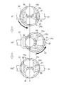
図2及び図3に示すように、第2の搬送ロボット14は、第1のアームユニット14aと、第2のアームユニット14bと、液受けカバー14cと、昇降回転部14dと、移動機構14eとを備えている。この第2の搬送ロボット14は、2台のアームユニット14a、14bを上下二段に有するダブルアームロボットである。なお、昇降回転部14dは保持回転部として機能する。
As shown in FIGS. 2 and 3, the
第1のアームユニット14aは、ハンド部21と、アーム部22とを備えている。なお、ハンド部21は基板保持部として機能する。
The
ハンド部21は、基板Wの外周面(側面)を複数個所から挟み込みこんで基板Wを把持する。このハンド部21は、把持機構(図示せず)により基板Wの把持及び開放を行うことが可能に形成されている。例えば、把持機構としては、基板Wの外周面に当接する複数の爪部を基板Wの両側から基板Wを挟むための組に分け、組ごとに接離させる(すなわち、近づかせたり、離れさせたりする)機構を用いることが可能である。
The
アーム部22は、昇降回転部14d上に連結されており、昇降回転部14dにより鉛直方向の軸A1に沿って昇降可能に、さらに、鉛直方向の軸A1を中心として回転可能に形成されている。このアーム部22は伸縮可能に形成されており、ハンド部21を保持してハンド部21を水平な直線方向に移動させる。したがって、アーム部22が前進及び後退することで、バッファユニット13や処理室15aに基板Wを搬入したり、それらから基板Wを搬出したりする。
The
第2のアームユニット14bは、第1のアームユニット14aと基本的に同じ構造であり、ハンド部21と、アーム部22とを備えている。これらは前述と同じ構造であるため、その説明を省略する。なお、第1のアームユニット14aのハンド部21と、第2のアームユニット14bのハンド部21は上下二段に設けられている。
The
液受けカバー14cは、第1のアームユニット14a及び第2のアームユニット14bを取り囲むように設けられ、各アーム部22の伸縮動作を妨げないように形成されている。この液受けカバー14cが存在するため、処理が終わった後の濡れた状態の基板Wを搬送する場合に基板W上から液が落下して跳ねたとしても、その液は液受けカバー14cに当たる。これにより、基板W上から落下した液が移動機構14eや部屋の床面に飛散することを抑えることができる。
The
昇降回転部14dは、第1のアームユニット14a及び第2のアームユニット14bの各アーム部22を保持して鉛直方向の軸A1に沿って移動し、第1のアームユニット14a及び第2のアームユニット14bを液受けカバー14cと共に昇降させる。また、昇降回転部14dは、鉛直方向の軸A1を回転軸(ロボット回転軸A1)として回転し、保持している各アーム部22を液受けカバー14cと共に回す。この昇降回転部14dは、昇降機構や回転機構(いずれも図示せず)を内蔵している。昇降回転部14dは電気的に制御ユニット16b(図1参照)に接続されており、その駆動が制御ユニット16bにより制御される。
The up-and-down
移動機構14eは、直線レール(移動軸)31と、移動駆動部32と、従動移動部33と、直線ガイドレール34と、直線ガイドブロック35と、回転部材36と、連結部材37とを備えている。この移動機構14eは電気的に制御ユニット16b(図1参照)に接続されており、その駆動が制御ユニット16bにより制御される。
The moving
直線レール31は、前述の第2の搬送方向に沿って延びるレールである。また、移動駆動部32は、直線レール31に沿って移動可能に、直線レール31上に設けられている。ただし、この移動駆動部32の移動は、必要に応じて制限される。例えば、図1において、上下に延びる第2のロボット搬送路を挟んで左側の処理室15aから、それに対向する右側の処理室15aに基板Wを搬送する場合(180度の旋回動作時)には、移動駆動部32の移動が制限される。従動移動部33は、昇降回転部14dの回転に応じ、直線レール31に沿って移動可能に直線レール31上に設けられている。この従動移動部33の上部には昇降回転部14dが回転可能に設けられている。
The
直線ガイドレール34は、直線レール31が延在する方向に直交する水平な方向に沿って移動駆動部32上に固定されて設けられている。また、直線ガイドブロック35は、直線ガイドレール34に沿って移動可能に、直線ガイドレール34上に設けられている。回転部材36は、直線ガイドブロック35上に回転可能に設けられている。この回転部材36の回転中心は、基板Wの中心を通る鉛直方向の軸A2(基板回転軸A2)上に配置されている。回転部材36は、連結部材37を介して昇降回転部14dの回転と一緒に回転する。連結部材37は、回転部材36上に設けられており、その上端は昇降回転部14dの下面に固定されている。この連結部材37は、直線ガイドブロック35が回転部材36と共に昇降回転部14dの回転に応じて直線ガイドレール34に沿って移動するよう、回転部材36と昇降回転部14dを連結している。
The
このような移動機構14eによれば、図4に示すように(各部の位置関係が模式的に示されている)、昇降回転部14dがロボット回転軸A1を回転中心として回転すると(左図から右図への変化)、昇降回転部14dに連結された回転部材36は基板回転軸A2を回転中心として回転しつつ、直線ガイドブロック35と共に直線ガイドレール34に沿って移動する。このとき、移動駆動部32の移動が制限され、移動駆動部32は停止している。このため、直線ガイドブロック35の直線移動に応じ、昇降回転部14dは従動移動部33が直線レール31に沿って移動駆動部32に対して接離するように従動移動部33と共に移動する。したがって、移動機構14eは、ロボット回転軸A1の移動軌跡が基板回転軸A2の移動軌跡と直交するように昇降回転部14dを移動させることになる。このような移動動作では、直線ガイドブロック35が、直線レール31と水平面内で直交する方向に直線移動するため、基板Wも回転(自転)しながら直線移動することになる。なお、ロボット回転軸A1と基板回転軸A2(直線ガイドブロック35の回転軸)とは一致せず、一定のズレ量(旋回オフセット量)が存在する。
According to such a moving
ここで、図5及び図6に示すように、第2の搬送ロボット14は、アーム部22の伸縮動作及び昇降回転部14dの回転動作(旋回動作)により水平な直線方向(直線レール31が延在する方向とは直交する方向)に基板Wを移動させて搬送する。第2の搬送ロボット14は、例えば、アーム部22の収縮動作により処理室15aから基板Wを搬出し、昇降回転部14dを回転させつつ直線レール31に沿って移動させて基板Wを搬送し、収縮動作により基板Wを処理室15aに搬入する。このとき、昇降回転部14dは回転するが、直線レール31に沿って移動するため、基板Wは一直線に移動する。このような移動旋回方式によれば、基板Wは直線移動するため、基板Wが直線移動以外の移動を行う場合に比べ、ハンド部21により把持された基板Wに作用する遠心力を抑えることができる。これにより、液盛り状態の基板W上から液が落下することを抑制することが可能となるので、基板表面の部分的な乾燥を抑え、基板品質の低下を抑制することができる。なお、液盛り状態とは、基板Wの主面(被処理面)上に液膜が存在する状態であり、液膜は表面張力で基板Wの主面に保持されている。
Here, as shown in FIGS. 5 and 6, the
(比較例)
比較例では、図7に示すように、基板Wは、アーム部22の伸縮動作により水平な直線方向に移動するが、昇降回転部14dの回転動作(旋回動作)によって水平面内において湾曲な線形状に移動する。これは、昇降回転部14dが直線レール31に沿って移動できないため、ロボット回転軸(ロボット旋回軸)A1が固定され、ロボット回転軸A1とアームユニット14a、14bに保持された基板W中心との距離(旋回オフセット)が一定の距離を保ったまま基板Wが旋回しながら搬送されるためである。このような単純旋回方式によれば、基板Wが直線移動以外の湾曲移動を行うため、ハンド部21により把持された基板Wに作用する遠心力が大きくなる。このため、液盛り状態の基板W上から液が落下しやすく、基板表面が部分的に乾燥して基板品質が低下する。
(Comparative example)
In the comparative example, as shown in FIG. 7, the substrate W moves in the horizontal linear direction by the expansion and contraction operation of the
(移動旋回方式及び単純旋回方式の遠心力の変化)
図8には、アーム部22の伸縮時と昇降回転部14dの旋回動作時の基板W上の加速度が計算されて示されている。なお、図8の縦軸は、基板W上の液が受ける最大遠心力(G)であり、Gは、重力加速度を1Gとしたときの比率で記載されている。図8に示すように、アーム部22を伸ばした状態から戻す動作(移動600mm)、昇降回転部14dの旋回動作(180度旋回)、また、アーム部22を伸ばす動作(移動600mm)の3つの加速度変化が示されている。なお、アーム部22の旋回動作では、基板W(例えば、直径300mmの基板)の外周端に発生する遠心力が旋回オフセット量を160mmとして計算されている。
(Changes in centrifugal force for moving and simple turning)
FIG. 8 shows the calculated acceleration on the substrate W when the
図8に示すように、アーム部22が収縮する場合には、延伸位置から収縮する初めに大きな加速度(0.2G程度)が発生しており、収縮位置側では、減速のマイナスの加速度が発生している。なお、実際には、移動開始や停止時には別な加速度が発生するため、このままの値で移動開始や停止ができるものではないが、旋回動作による遠心力との比較はある程度可能である。
As shown in FIG. 8, when the
比較例の単純旋回方式では(図7参照)、180度旋回時の遠心力は0.31Gで一定になっている。これに対し、本実施形態の移動旋回方式では(図5参照)、180度旋回時の遠心力は山形の曲線となり、最大値でも単純旋回の半分の加速度、約0.15Gになっている。これは、単純旋回方式では、基板半径+旋回オフセット量の遠心力が常に作用するのに対し、移動旋回方式では、旋回オフセット量をゼロにすることができるため、基板半径分の遠心力が、直線レール31の延伸方向への昇降回転部14dの移動により、基板移動方向と直交する水平な方向の加速度によって弱くなるためである。これにより、基板W上の液膜が基板W外に放出される現象を大幅に低減することが可能となる。あるいは、昇降回転部14dの回転速度を上げて、回転移動時間を短縮することも可能となる。
In the simple turning method of the comparative example (see FIG. 7), the centrifugal force during the turning of 180 degrees is constant at 0.31G. On the other hand, in the moving and turning method of this embodiment (see FIG. 5), the centrifugal force at the time of turning 180 degrees is a mountain-shaped curve, and the maximum value is about half the acceleration of simple turning, about 0.15G. This is because, in the simple turning method, the centrifugal force of the substrate radius + the turning offset amount always acts, whereas in the moving turning method, the turning offset amount can be zero, so the centrifugal force for the substrate radius is This is because the movement of the up-and-down
ここで、図9には、単純旋回方式の遠心力と移動旋回方式の遠心力が基板搬送時間(180度旋回時の基板移動時間)ごとに示されている。なお、基板搬送中の加速度変化のうち最大値が示されている。図9に示すように、基板搬送時間が同じである場合には、移動旋回方式の遠心力の方が、単純旋回方式に比べて二分の一以下程度に小さくなっている。また、例えば、アーム部22の収縮動作の最大加速度である約0.18Gに加速度を抑えるためには、図9に示すように、単純旋回方式では、1.3秒で180度旋回を行うが、移動旋回方式では、0.9秒で180度旋回を行うことが可能である。これにより、昇降回転部14dの回転移動時間を短くし、基板搬送時間を短縮することができる。
Here, in FIG. 9, the centrifugal force of the simple turning method and the centrifugal force of the moving turning method are shown for each substrate transport time (substrate moving time when turning 180 degrees). In addition, the maximum value is shown among the acceleration changes during board | substrate conveyance. As shown in FIG. 9, when the substrate transport time is the same, the centrifugal force of the moving and turning method is smaller than about one half or less than that of the simple turning method. Further, for example, in order to suppress the acceleration to about 0.18 G which is the maximum acceleration of the contraction operation of the
(基板処理工程)
次に、前述の基板処理装置10が行う基板処理の流れについて説明する。なお、基板Wに対して2種類の処理を行う場合には、図1において、上下に延びる第2のロボット搬送路を挟んで左側の4つの処理室15a(以下、第1の処理室15aとすることがある)と、右側の4つの処理室15a(以下、第2の処理室15aとすることがある)が異なる処理を行うように設定されている。異なる処理を行う場合、第1の処理室は、第1の処理が行われる処理室であり、第2の処理室は、第1の処理の次の処理(第2の処理)が行われる処理室である。
(Substrate processing process)
Next, the flow of substrate processing performed by the above-described
まず、未処理の基板Wが開閉ユニット11内の専用ケースから第1の搬送ロボット12により取り出される。第1の搬送ロボット12は、必要に応じて第1のロボット移動路に沿って移動し、停止する。そして、第1の搬送ロボット12は、停止場所で旋回して未処理の基板Wをバッファユニット13に搬入する。これにより、バッファユニット13には、未処理の基板Wが収納される。
First, the unprocessed substrate W is taken out from the dedicated case in the opening /
その後、バッファユニット13内の未処理の基板Wは、第2の搬送ロボット14により取り出される。第2の搬送ロボット14は、必要に応じて第2のロボット移動路に沿って移動し、停止する。そして、第2の搬送ロボット14は、停止場所で旋回して未処理の基板Wを所望の第1の処理室15aに搬入する。これにより、第1の処理室15a内に未処理の基板Wがセットされる。その後、第1の処理室15aにおいて基板Wに第1の処理が行われる。
Thereafter, the unprocessed substrate W in the buffer unit 13 is taken out by the
第1の処理室15aでの処理が終了すると、第1の処理室15a内から処理済の基板Wが第2の搬送ロボット14により取り出される。第2の搬送ロボット14は、180°旋回して処理済の基板Wを第2の処理室15aに搬入する。これにより、第2の処理室15a内に処理済の基板Wがセットされる。その後、第2の処理室15aにおいて基板Wに第2の処理が行われる。
When the processing in the
第2の処理室15aでの処理が終了すると、第2の処理室15a内から処理済の基板Wが第2の搬送ロボット14により取り出される。第2の搬送ロボット14は、必要に応じて第2のロボット移動路に沿って移動し、停止する。そして、第2の搬送ロボット14は、停止場所で旋回して処理済の基板Wをバッファユニット13に搬入する。これにより、バッファユニット13には、処理済の基板Wが収納される。
When the processing in the
その後、バッファユニット13内の処理済の基板Wは、第1の搬送ロボット12により取り出される。第1の搬送ロボット12は、必要に応じて第1のロボット移動路に沿って移動し、停止する。そして、第1の搬送ロボット12は、停止場所で旋回して処理済の基板Wを所望の専用ケースに搬入する。これにより、専用ケースには、処理済の基板Wが収納される。
Thereafter, the processed substrate W in the buffer unit 13 is taken out by the
このような基板搬送工程においては、2種類の処理を行うため、バッファユニット13に収納された未処理の基板Wは、第2の搬送ロボット14の第1のアームユニット14aにより、まず第1の処理室15aにセットされて処理される。処理が終了したら、処理済の基板Wが第2の搬送ロボット14の第2のアームユニット14bにより取り出され、180度の旋回動作により第2の処理室2にセットされる。このときの搬送が、基板表面上に液膜が形成された液盛り状態での搬送になる。第2の処理室15aでは次工程の処理が実施され、処理終了後、処理済の基板Wが第2のアームユニット14bにより第2の処理室15aからバッファユニット13に搬入される。バッファユニット13に搬入された処理済の基板Wは、第1の搬送ロボット12で専用ケースに戻される。なお、バッファユニット13からの基板搬出と、バッファユニット13に対する基板搬入は、ダブルアームの片方のドライハンドでの搬送になる。第1の処理室15aから第2の処理室15aまでの搬送は、もう片方のウエットハンドでの搬送となる。
In such a substrate transfer process, since two types of processing are performed, an unprocessed substrate W stored in the buffer unit 13 is firstly processed by the
また、上述したように、第2の搬送ロボット14は、2台のアームユニット14a、14bを上下二段に有している。濡れた状態の基板Wを搬送する際に使用するウエットハンドとなるアームユニットは、搬送中に基板Wから放出された液が他方のアームユニットに付着することを抑制するため、2台のアームユニット14a、14bのうち、下段に位置するアームユニット(本実施形態の場合には第2のアームユニット14b)を使用する。ドライハンドは、上段のアームユニット(本実施形態の場合には第1のアームユニット14a)を使用する。
Further, as described above, the
ここで、濡れた基板Wの搬送では、基板表面の乾燥を防止する必要があるため、できるだけ基板W上の水を基板表面から落とさないことが必要である。このため、通常の乾いた基板Wを搬送する場合よりも、基板Wに作用する加速度を制限した動作が必要である。濡れた状態の基板Wに作用する加速度としては、処理室15aから取り出す移動動作時の加速、減速時の加速度、次の処理室15aへの搬送時の直線移動の加速、減速時の加速度、そして旋回動作における加速、減速の加速度と、旋回中の遠心力である。特に、遠心力は、第2の搬送ロボット14の回転中心(旋回中心)から板状基板の外端までの最大距離で決まるため、基板サイズが大きいと、処理室15aからの移動時の直線移動の加速度よりも大きくなる。
Here, in transporting the wet substrate W, it is necessary to prevent the substrate surface from drying, and therefore, it is necessary to prevent water on the substrate W from dropping from the substrate surface as much as possible. For this reason, the operation | movement which restricted the acceleration which acts on the board | substrate W is required rather than the case where the normal dry board | substrate W is conveyed. As the acceleration acting on the wet substrate W, acceleration at the time of moving operation to be taken out from the
また、第2の搬送ロボット14の回転中心と基板中心が一致するように伸縮機構を設けるためには、第2の搬送ロボット14の回転中心まで基板中心を移動する伸縮機構を設けるなど、アームユニット14a、14bのアーム長さを長くする必要がある。しかしながら、この場合にはロボット機構の旋回範囲が最小ではなくなり、ロボット機構を載置する搬送スペースの増加につながることから、省スペース化が求められるクリーンルームに設置する装置としては好ましくない。したがって、省スペース化のために第2の搬送ロボット14の回転中心と基板中心が一致しない状態で基板Wを旋回させる搬送が行われるので、基板自身の回転(自転)に加え、軸のズレ量(旋回オフセット量)分だけ遠心力が増加することになる。さらに、遠心力は、旋回角速度の2乗に比例するため、短時間の高速旋回は難しくなる。
Further, in order to provide an expansion / contraction mechanism so that the rotation center of the
そこで、濡れた基板Wを搬送するウエットロボットでは、濡れた基板Wを保持して処理室15a間を搬送するときには、できるだけ遠心力が作用しないように旋回動作を少なくして移動したいが、処理室レイアウト的には、移動する第2の搬送ロボット14を中央にして両側に異なる処理室15aを配置する方が、処理液や排気等の引回しが有利になる。このため、第2の搬送ロボット14は180度旋回して基板搬送することが多い。このため、第2の搬送ロボット14は、基板W上の水膜が次工程処理に十分な量を確保できる最大の旋回速度で移載動作を行うことになる。
Therefore, in the wet robot that transports the wet substrate W, when the wet substrate W is held and transported between the
なお、多軸のロボット制御方法として、ハンド先端の軌跡を制御して部材搬送させる制御手法があるが、処理室15a内からの取出し、旋回、次の処理室15aへのセットを直線移動で制御するには、関係するすべての移動軸をサーボモータにして同期制御する必要がある。モータ制御コントローラも高額になり、リンク機構で動作するコンパクトな伸縮直動アームもモータを配置するスペースが必要になり、ロボットの占有エリアが増大する。
In addition, as a multi-axis robot control method, there is a control method in which the trajectory of the hand tip is controlled to convey the member. However, taking out from the
ところが、本実施形態に係る移動旋回方式によれば、基板Wは直線移動するため、基板Wが直線移動以外の移動を行う場合に比べ、第1のアームユニット14aにより水平に保持された基板Wに作用する遠心力を抑えることが可能となる。これにより、基板W上の液膜が基板W外に放出される現象を大幅に低減することができ、あるいは、昇降回転部14dの回転速度を上げて、旋回時間を短縮することもできる。すなわち、濡れた基板Wを搬送するウエットロボットにおいて、装置スペースを増やさずに、装置コストアップを抑えつつ、基板W上からの液落下を少なくし、また、基板搬送時間を短くすることができる。
However, according to the moving and turning method according to the present embodiment, since the substrate W moves linearly, the substrate W held horizontally by the
以上説明したように、本実施形態によれば、昇降回転部14dの回転軸から基板Wの中心をずらして基板Wを第1のアームユニット14aにより水平に保持し、その水平に保持した基板Wを回しつつ水平な直線方向に搬送するよう、昇降回転部14dの回転に応じて前述の水平な直線方向に交わる水平な方向(例えば、直線方向に直交する水平な方向)に昇降回転部14dを移動させる。これにより、基板Wは直線移動するため、基板Wが直線移動以外の移動を行う場合に比べ、昇降回転部14dの回転により基板Wに作用する遠心力を抑制することが可能になるので、液盛り状態の基板表面から液が落下することを抑えることができる。
As described above, according to the present embodiment, the substrate W is horizontally held by the
<他の実施形態>
前述の実施形態においては、二つのアームユニット14a、14bを保持する保持回転部として、昇降回転部14dを例示したが、これに限るものではなく、例えば、昇降機構を有していない保持回転部を用いることも可能であり、その機構は特に限定されるものではない。また、二つのアームユニット14a、14bを設けているが、その数は一つでも二つ以上でも良く、特に限定されるものではない。
<Other embodiments>
In the above-described embodiment, the up-and-
また、前述の実施形態においては、基板Wを保持するハンド部として、基板Wを把持するハンド部21を例示したが、これに限るものではなく、例えば、基板Wを下面から支持するハンド部を用いることも可能であり、その機構は特に限定されるものではない。
In the above-described embodiment, the
また、前述の実施形態においては、基板Wの搬送方向に直交する水平な方向に昇降回転部14dを移動させることを例示したが、これに限るものではなく、例えば、基板Wの搬送方向に交わる方向であれば良い。
In the above-described embodiment, the lifting / lowering
また、前述の実施形態においては、第2の搬送ロボット14のロボット本体の移動機構として、直線レール31のリニアガイドを用いた直線移動変換機構を用いることを例示したが、これに限るものではなく、例えば、ロボット回転軸A1と同期して回転する別のモータでロボット本体を移動させるようにしてもよい。リニアガイドではなく、偏芯カム機構でロボット本体を移動させることも可能である。また、直線レール31をロボット本体のスライド軸としているが、直線レール31と平行なスライド軸を設けてロボット本体を移動させるようにしても良い。
In the above-described embodiment, the linear movement conversion mechanism using the linear guide of the
また、前述の実施形態においては、二種類の処理室15aを用いることを例示したが、これに限るものではなく、例えば、三種類の処理室15aを用いるようにしても良い。この場合には、処理1→処理2→処理3の順に処理を行ってからバッファユニット13に処理済の基板Wを戻す作業になる。例えば、処理2を行う処理室15aの数を4つにするが、これは、処理2を行う処理室15aの処理が処理1又は処理3に比べて2倍の時間を要することを想定し、台数を倍に設定しているためである。
In the above-described embodiment, the use of two types of
また、前述の実施形態においては、搬送する基板Wとして、円形の基板Wを例示して説明したが、これに限るものではなく、例えば、四角形や多角形形状の基板Wであってもよい。この場合、「基板の中心」とは、基板の重心であればよい。 In the above-described embodiment, the circular substrate W has been described as an example of the substrate W to be transferred. However, the substrate W is not limited to this, and may be a rectangular or polygonal substrate W, for example. In this case, the “center of the substrate” may be the center of gravity of the substrate.
以上、本発明のいくつかの実施形態を説明したが、これらの実施形態は、例として提示したものであり、発明の範囲を限定することは意図していない。これら新規な実施形態は、その他の様々な形態で実施されることが可能であり、発明の要旨を逸脱しない範囲で、種々の省略、置き換え、変更を行うことができる。これら実施形態やその変形は、発明の範囲や要旨に含まれるとともに、特許請求の範囲に記載された発明とその均等の範囲に含まれる。 As mentioned above, although some embodiment of this invention was described, these embodiment is shown as an example and is not intending limiting the range of invention. These novel embodiments can be implemented in various other forms, and various omissions, replacements, and changes can be made without departing from the scope of the invention. These embodiments and modifications thereof are included in the scope and gist of the invention, and are included in the invention described in the claims and the equivalents thereof.
10 基板処理装置
14 第2の搬送ロボット
14a 第1のアームユニット
14d 昇降回転部
14e 移動機構
15 基板処理部
15a 処理室
31 直線レール
33 従動移動部
34 直線ガイドレール
35 直線ガイドブロック
36 回転部材
37 連結部材
W 基板
DESCRIPTION OF
Claims (5)
前記アームユニットを保持し、鉛直方向に延びる軸を回転中心として回転する保持回転部と、
前記保持回転部を移動させる移動機構と、
を備え、
前記アームユニットは、前記保持回転部の回転軸から前記基板の中心をずらして前記基板を水平に保持し、
前記移動機構は、前記アームユニットにより水平に保持された前記基板を回しつつ水平な直線方向に搬送するよう、前記保持回転部の回転に応じて前記直線方向に交わる水平な方向に前記保持回転部を移動させることを特徴とする基板搬送装置。 An arm unit for holding a substrate;
A holding rotation unit that holds the arm unit and rotates about an axis extending in the vertical direction;
A moving mechanism for moving the holding rotation unit;
With
The arm unit holds the substrate horizontally by shifting the center of the substrate from the rotation axis of the holding rotation unit,
The holding mechanism rotates in the horizontal direction intersecting the linear direction according to the rotation of the holding rotary unit so that the moving mechanism conveys the substrate held horizontally by the arm unit in a horizontal linear direction while rotating. A substrate transfer apparatus characterized by moving the substrate.
前記直線方向に延びる直線ガイドレールと、
前記直線ガイドレール上に設けられ、前記直線ガイドレールに沿って移動する直線ガイドブロックと、
前記直線ガイドブロック上に設けられ、回転する回転部材と、
前記直線ガイドブロックが前記回転部材と共に前記保持回転部の回転に応じて前記直線ガイドレールに沿って移動するよう、前記回転部材と前記保持回転部を連結する連結部材と、
前記直線ガイドレールに直交する水平な方向に延びる直線レールと、
前記直線レール上に設けられて前記保持回転部に連結され、前記直線ガイドブロックの移動に応じて前記直線レールに沿って移動する従動移動部と、
を具備することを特徴とする請求項1又は請求項2に記載の基板搬送装置。 The moving mechanism is
A linear guide rail extending in the linear direction;
A linear guide block provided on the linear guide rail and moving along the linear guide rail;
A rotating member provided on the linear guide block and rotating;
A connecting member that connects the rotating member and the holding rotating unit so that the linear guide block moves along with the rotating member along the linear guide rail according to the rotation of the holding rotating unit;
A linear rail extending in a horizontal direction perpendicular to the linear guide rail;
A follower moving unit provided on the linear rail and connected to the holding rotation unit, and moves along the linear rail according to the movement of the linear guide block;
The substrate transfer apparatus according to claim 1, further comprising:
前記第1の基板処理部により前記液膜が表面に形成された基板を搬送する請求項1から請求項3のいずれか一項に記載の基板搬送装置と、
前記基板搬送装置により搬送された前記基板を処理する第2の基板処理部と、
を備えることを特徴とする基板処理装置。 A first substrate processing unit for forming a liquid film of the processing liquid on the substrate;
The substrate transfer apparatus according to any one of claims 1 to 3, wherein the substrate having the liquid film formed on a surface thereof is transferred by the first substrate processing unit.
A second substrate processing unit for processing the substrate transported by the substrate transport device;
A substrate processing apparatus comprising:
前記搬出された基板を前記基板搬送装置により搬送する工程と、
前記基板を処理するための第2の処理室に、前記搬送された基板を前記基板搬送装置により搬入する工程と、
を有することを特徴とする基板処理方法。 The step of carrying out the substrate on which the liquid film of the processing solution is formed from the first processing chamber for processing the substrate by the substrate transfer apparatus according to any one of claims 1 to 3. ,
A step of transporting the unloaded substrate by the substrate transport device;
Carrying the transported substrate into the second processing chamber for processing the substrate by the substrate transport device;
A substrate processing method comprising:
Priority Applications (1)
| Application Number | Priority Date | Filing Date | Title |
|---|---|---|---|
| JP2016073093A JP6637362B2 (en) | 2016-03-31 | 2016-03-31 | Substrate transfer device, substrate processing device, and substrate processing method |
Applications Claiming Priority (1)
| Application Number | Priority Date | Filing Date | Title |
|---|---|---|---|
| JP2016073093A JP6637362B2 (en) | 2016-03-31 | 2016-03-31 | Substrate transfer device, substrate processing device, and substrate processing method |
Publications (2)
| Publication Number | Publication Date |
|---|---|
| JP2017183666A true JP2017183666A (en) | 2017-10-05 |
| JP6637362B2 JP6637362B2 (en) | 2020-01-29 |
Family
ID=60007210
Family Applications (1)
| Application Number | Title | Priority Date | Filing Date |
|---|---|---|---|
| JP2016073093A Active JP6637362B2 (en) | 2016-03-31 | 2016-03-31 | Substrate transfer device, substrate processing device, and substrate processing method |
Country Status (1)
| Country | Link |
|---|---|
| JP (1) | JP6637362B2 (en) |
Cited By (5)
| Publication number | Priority date | Publication date | Assignee | Title |
|---|---|---|---|---|
| JP2019197799A (en) * | 2018-05-09 | 2019-11-14 | 芝浦メカトロニクス株式会社 | Substrate holding device, substrate conveyance device, and substrate conveyance method |
| JP2020167184A (en) * | 2019-03-28 | 2020-10-08 | 東京エレクトロン株式会社 | Substrate processing apparatus and substrate processing method |
| CN113508456A (en) * | 2020-02-05 | 2021-10-15 | 株式会社安川电机 | Conveying system, conveying method and conveying device |
| JP7304738B2 (en) | 2019-05-17 | 2023-07-07 | 株式会社Screenホールディングス | Substrate processing equipment |
| JP7313229B2 (en) | 2019-08-07 | 2023-07-24 | ニデックインスツルメンツ株式会社 | processing system |
-
2016
- 2016-03-31 JP JP2016073093A patent/JP6637362B2/en active Active
Cited By (7)
| Publication number | Priority date | Publication date | Assignee | Title |
|---|---|---|---|---|
| JP2019197799A (en) * | 2018-05-09 | 2019-11-14 | 芝浦メカトロニクス株式会社 | Substrate holding device, substrate conveyance device, and substrate conveyance method |
| JP7126856B2 (en) | 2018-05-09 | 2022-08-29 | 芝浦メカトロニクス株式会社 | Substrate gripping device, substrate transfer device, and substrate transfer method |
| JP2020167184A (en) * | 2019-03-28 | 2020-10-08 | 東京エレクトロン株式会社 | Substrate processing apparatus and substrate processing method |
| JP7253955B2 (en) | 2019-03-28 | 2023-04-07 | 東京エレクトロン株式会社 | SUBSTRATE PROCESSING APPARATUS AND SUBSTRATE PROCESSING METHOD |
| JP7304738B2 (en) | 2019-05-17 | 2023-07-07 | 株式会社Screenホールディングス | Substrate processing equipment |
| JP7313229B2 (en) | 2019-08-07 | 2023-07-24 | ニデックインスツルメンツ株式会社 | processing system |
| CN113508456A (en) * | 2020-02-05 | 2021-10-15 | 株式会社安川电机 | Conveying system, conveying method and conveying device |
Also Published As
| Publication number | Publication date |
|---|---|
| JP6637362B2 (en) | 2020-01-29 |
Similar Documents
| Publication | Publication Date | Title |
|---|---|---|
| JP2017183666A (en) | Substrate carrier device, substrate processing apparatus and substrate processing method | |
| JP5139253B2 (en) | Vacuum processing device and vacuum transfer device | |
| JP7246147B2 (en) | SUBSTRATE PROCESSING APPARATUS AND SUBSTRATE PROCESSING METHOD | |
| KR101453189B1 (en) | Carrier device | |
| JP5792981B2 (en) | Plate member reversal system and reversal transfer method thereof | |
| KR101429827B1 (en) | Conveying system | |
| KR19980041847A (en) | Substrate processing system | |
| KR20160071463A (en) | Substrate carrier apparatus | |
| CN108701636A (en) | Substrate board treatment | |
| JP2013165241A (en) | Transporting apparatus | |
| KR102227108B1 (en) | Substrate transport apparatus, substrate processing apparatus and substrate processing method | |
| KR102164067B1 (en) | Substrate processing apparatus and substrate processing method | |
| KR102588614B1 (en) | Industrial robot and manufacturing system | |
| JP7412865B2 (en) | Substrate transfer robot, substrate transfer system, and substrate transfer method | |
| JP2014170828A (en) | Determination method for substrate transfer path, substrate transfer device, substrate processing device and program | |
| CN109585348A (en) | Substrate board treatment and substrate processing method using same | |
| JP2018085354A (en) | Reversing machine, reversing unit, inversion method and substrate processing method | |
| JP4199432B2 (en) | Robot apparatus and processing apparatus | |
| JP2012056706A (en) | Device and method for transferring substrate | |
| JP2019021934A (en) | Substrate transfer method | |
| JP7137408B2 (en) | SUBSTRATE PROCESSING APPARATUS AND SUBSTRATE PROCESSING METHOD | |
| KR102449001B1 (en) | Substrate processing apparatus and substrate processing method | |
| JP2020021794A (en) | Carrier system | |
| JP2010034219A (en) | Substrate treatment unit, and substrate treatment device | |
| JP2020178125A (en) | Substrate carrier device, substrate processing apparatus, and substrate processing method |
Legal Events
| Date | Code | Title | Description |
|---|---|---|---|
| A621 | Written request for application examination |
Free format text: JAPANESE INTERMEDIATE CODE: A621 Effective date: 20190328 |
|
| A977 | Report on retrieval |
Free format text: JAPANESE INTERMEDIATE CODE: A971007 Effective date: 20191206 |
|
| TRDD | Decision of grant or rejection written | ||
| A01 | Written decision to grant a patent or to grant a registration (utility model) |
Free format text: JAPANESE INTERMEDIATE CODE: A01 Effective date: 20191217 |
|
| A61 | First payment of annual fees (during grant procedure) |
Free format text: JAPANESE INTERMEDIATE CODE: A61 Effective date: 20191220 |
|
| R150 | Certificate of patent or registration of utility model |
Ref document number: 6637362 Country of ref document: JP Free format text: JAPANESE INTERMEDIATE CODE: R150 |