JP2017181061A - Measuring method and device for vertical creep force between wheel of railway vehicle and rail - Google Patents
Measuring method and device for vertical creep force between wheel of railway vehicle and rail Download PDFInfo
- Publication number
- JP2017181061A JP2017181061A JP2016063528A JP2016063528A JP2017181061A JP 2017181061 A JP2017181061 A JP 2017181061A JP 2016063528 A JP2016063528 A JP 2016063528A JP 2016063528 A JP2016063528 A JP 2016063528A JP 2017181061 A JP2017181061 A JP 2017181061A
- Authority
- JP
- Japan
- Prior art keywords
- rail
- wheel
- creep force
- railway vehicle
- strain
- Prior art date
- Legal status (The legal status is an assumption and is not a legal conclusion. Google has not performed a legal analysis and makes no representation as to the accuracy of the status listed.)
- Granted
Links
- 238000000034 method Methods 0.000 title claims description 16
- 238000004458 analytical method Methods 0.000 claims description 18
- 238000005259 measurement Methods 0.000 claims description 16
- 238000006073 displacement reaction Methods 0.000 claims description 6
- 238000001514 detection method Methods 0.000 claims description 4
- 239000000523 sample Substances 0.000 claims description 4
- 238000000691 measurement method Methods 0.000 claims description 3
- 241000219098 Parthenocissus Species 0.000 claims 1
- 230000000694 effects Effects 0.000 abstract description 2
- 238000009434 installation Methods 0.000 description 8
- 230000005856 abnormality Effects 0.000 description 4
- 238000005516 engineering process Methods 0.000 description 3
- 238000005452 bending Methods 0.000 description 2
- 238000011161 development Methods 0.000 description 2
- 239000000314 lubricant Substances 0.000 description 2
- 238000005461 lubrication Methods 0.000 description 2
- 238000012545 processing Methods 0.000 description 2
- 238000011160 research Methods 0.000 description 2
- 238000012360 testing method Methods 0.000 description 2
- 241001669679 Eleotris Species 0.000 description 1
- 238000009530 blood pressure measurement Methods 0.000 description 1
- 238000004364 calculation method Methods 0.000 description 1
- 238000010586 diagram Methods 0.000 description 1
- 238000002347 injection Methods 0.000 description 1
- 239000007924 injection Substances 0.000 description 1
- 239000000463 material Substances 0.000 description 1
- 229910052751 metal Inorganic materials 0.000 description 1
- 239000002184 metal Substances 0.000 description 1
- 150000002739 metals Chemical class 0.000 description 1
- 238000012544 monitoring process Methods 0.000 description 1
- 239000013307 optical fiber Substances 0.000 description 1
- 239000000243 solution Substances 0.000 description 1
- 238000010897 surface acoustic wave method Methods 0.000 description 1
Images


Abstract
Description
本発明は、鉄道車両の車輪とレールの接触部に作用する荷重のうち、車両進行方向の前後方向の荷重、すなわち縦クリープ力を測定する方法、及びこの測定方法を実施する装置に関するものである。 The present invention relates to a method of measuring a longitudinal load in a vehicle traveling direction, that is, a longitudinal creep force, among loads acting on a contact portion between a wheel and a rail of a railway vehicle, and an apparatus for performing this measurement method. .
車輪と車軸が一体の輪軸を備えた台車の場合、曲線区間を通過する際に、後軸の車輪とレールの接触部に作用する縦クリープ力は、台車をヨー方向に回転する力を発生させて先頭軸外軌側の横圧を増加させる方向に作用する(非特許文献1)。 In the case of a truck with an integrated wheel and wheel axle, the vertical creep force acting on the contact part between the rear wheel and the rail when passing through the curved section generates a force that rotates the carriage in the yaw direction. Thus, it acts in the direction of increasing the lateral pressure on the front shaft outer gauge side (Non-Patent Document 1).
前記横圧が増加すると、曲線区間を通過する際に脱線しやすくなる。従って、鉄道車両の車輪とレールの接触部に作用する荷重のうち、前記縦クリープ力を測定することは、鉄道車両の曲線通過性能を向上するうえで大変有用である。 When the lateral pressure increases, derailment easily occurs when passing through the curved section. Therefore, it is very useful to measure the longitudinal creep force among loads acting on the contact portion between the wheel and rail of the railway vehicle in order to improve the curve passing performance of the railway vehicle.
また、車輪が摩耗して曲線通過時に輪径差がとれなくなった場合は縦クリープ力が変化する。従って、縦クリープ力を測定することによって、車輪の摩耗状況を評価することもできる(非特許文献2)。 In addition, when the wheel wears and the wheel diameter difference cannot be taken when passing through the curve, the longitudinal creep force changes. Therefore, it is possible to evaluate the wear state of the wheel by measuring the longitudinal creep force (Non-Patent Document 2).
さらに、操舵台車では、操舵が適切に行われる場合は作用する縦クリープ力が小さいが、操舵が適切に行われない場合は作用する縦クリープ力が大きくなる。従って、縦クリープ力を測定することで操舵台車における操舵装置の異常を検知することができる(非特許文献3)。 Further, in the steering cart, the vertical creep force that acts when steering is properly performed is small, but when the steering is not performed appropriately, the vertical creep force that acts is large. Therefore, the abnormality of the steering device in the steering cart can be detected by measuring the longitudinal creep force (Non-patent Document 3).
また、操舵を行わない通常の台車の場合も、例えば軸箱の前後方向の支持装置が破断して異常が発生すると、走行条件、走行速度が同一であっても縦クリープ力が大きく変化する。従って、通常の台車の場合も、縦クリープ力を測定することで、異常を検知することができる。特に直線区間では、軸箱の前後支持が正常でない場合は、軸箱の前後支持が正常な場合と比較して作用する縦クリープ力が大きくなるので、直線区間で地上側から縦クリープ力を測定することは有効である。 Also, in the case of a normal carriage that does not perform steering, for example, if the support device in the front-rear direction of the axle box breaks and an abnormality occurs, the vertical creep force changes greatly even if the running conditions and the running speed are the same. Therefore, even in the case of a normal carriage, an abnormality can be detected by measuring the longitudinal creep force. Especially in the straight section, when the longitudinal support of the axle box is not normal, the vertical creep force acting is larger than when the longitudinal support of the axle box is normal, so the longitudinal creep force is measured from the ground side in the straight section. It is effective to do.
この鉄道車両の車輪とレールの接触部に作用する縦クリープ力を測定する方法として、車輪に発生するひずみや、モノリンク式軸箱支持装置を備えた台車におけるモノリンク力から測定する方法が開示されている(例えば特許文献1、非特許文献4)。
As a method of measuring the longitudinal creep force acting on the contact portion between the rail and the wheel of the railway vehicle, a method of measuring from the strain generated in the wheel and the monolink force in the carriage equipped with the monolink type axle box support device is disclosed. (For example,
特許文献1、非特許文献4に開示されているように、鉄道車両の車輪とレールの接触部に作用する縦クリープ力の測定は、従来、車上側から行われていた。そのため、レールと車輪間の潤滑条件を地上側から変更した場合も、縦クリープ力の変化の確認を車上側で行わなければならず、変更した潤滑条件が最適かどうかの確認をタイムリーに行うことができなかった。また、縦クリープ力から車輪摩耗状況や軸箱の前後方向の支持を行うモノリンクの異常を検知しようとする場合、車両毎にモノリンクの荷重を測定する必要があった。
As disclosed in
本発明が解決しようとする問題点は、従来は、鉄道車両の車輪とレールの接触部に作用する縦クリープ力を地上側から測定する技術は提案されていなかったという点である。 The problem to be solved by the present invention is that, conventionally, no technique has been proposed for measuring the longitudinal creep force acting on the contact portion between the wheel and rail of a railway vehicle from the ground side.
本発明の目的は、鉄道車両の車輪とレールの接触部に作用する縦クリープ力を地上側から測定可能にすることである。 An object of the present invention is to make it possible to measure a longitudinal creep force acting on a contact portion between a wheel and a rail of a railway vehicle from the ground side.
鉄道車両の走行時に車輪がレールに接触した際、レールに発生する応力には、輪重による応力、横圧による応力、縦クリープ力による応力、スピンによる応力の4つがある。 When the wheel contacts the rail during traveling of the railway vehicle, there are four stresses generated on the rail: stress due to wheel load, stress due to lateral pressure, stress due to longitudinal creep force, and stress due to spin.
上記応力のうち、スピンによる応力の影響は元々少ないので、無視することができる。また、横圧による応力の影響がある場合は、例えば図8(a)に示す位置にひずみゲージ4a,4bを貼付し、このひずみゲージ4a,4bを図8(b)に示すように結線してホイートストンブリッジ回路Bを組むことで、除去することができる。すなわち、レール1のウェブ1aの表裏面の、レール1の横断面における幅方向中心線CLに対して線対称となる位置にひずみゲージ4a,4bを貼付することで、横圧による応力の影響を除去することができる。なお、図8中のRはダミー抵抗である。
Among the stresses, the influence of the stress due to the spin is originally small and can be ignored. Further, when there is an influence of stress due to the lateral pressure, for example, the
従って、車輪がレールに接触した際にレールに発生する応力のうちの、輪重による応力と縦クリープ力による応力を分離することができれば、レールに発生する応力から縦クリープ力を測定することができる。 Therefore, if the stress caused by the wheel load and the stress caused by the longitudinal creep force can be separated from the stresses produced on the rail when the wheel contacts the rail, the longitudinal creep force can be measured from the stress generated on the rail. it can.
本発明は上記考えに基づいてなされたものである。
すなわち、本発明は、レールを支える枕木の隣り合う枕木間の中間位置に輪重を負荷し、前記中間位置からレールの敷設方向前後にそれぞれ等間隔隔てた2か所においてレールに発生する主応力方向の応力(主応力)を測定する。
The present invention has been made based on the above idea.
That is, the present invention loads the wheel load at an intermediate position between adjacent sleepers that support the rail, and the main stress generated in the rail at two locations that are equally spaced from the intermediate position in the rail installation direction. Measure the direction stress (principal stress).
負荷した輪重により発生する応力の場はレールの敷設方向前後で対称になるため、輪重によるレールの主応力は同一となる。従って、レールの敷設方向前後2か所の測定位置で輪重によりレールに発生する主応力を測定し、これら測定した主応力の差をとることで輪重による主応力が除去され、残った主応力差は縦クリープ力によるものとなる。 Since the field of stress generated by the loaded wheel load is symmetrical before and after the rail installation direction, the main stress of the rail by the wheel load is the same. Therefore, the main stress generated in the rail due to the wheel load is measured at two measurement positions before and after the rail laying direction, and the main stress due to the wheel load is removed by taking the difference between the measured main stresses. The stress difference is due to the longitudinal creep force.
よって、前記2か所の測定位置において測定された主応力の、輪重を隣り合う枕木間の中間に負荷した場合の差(以下、前後の主応力差という)と、縦クリープ力を負荷した場合の前後の主応力差の関係を理論解析又は有限要素解析(以下、FEM解析という。)により予め求めておけば、この予め求めておいた関係と前記測定した縦クリープ力による主応力から縦クリープ力を得ることができる。これが本発明の縦クリープ力測定方法である。 Therefore, the difference between the main stress measured at the two measurement positions when the wheel load is applied in the middle between the adjacent sleepers (hereinafter referred to as the main stress difference between the front and rear) and the longitudinal creep force are applied. If the relationship between the main stress difference before and after the case is obtained in advance by theoretical analysis or finite element analysis (hereinafter referred to as FEM analysis), the longitudinal stress is calculated from the relationship obtained in advance and the principal stress due to the measured longitudinal creep force. Creep force can be obtained. This is the longitudinal creep force measuring method of the present invention.
上記本発明では、前記主応力の測定を、レールの横断面の幅方向中心線に対して線対称となるレールのウェブの表裏面で行えば、これら測定子を結線したブリッジ回路を組むことで、横圧による応力の影響を除去することができる。 In the present invention, if the measurement of the main stress is performed on the front and back surfaces of the rail web that is line-symmetric with respect to the center line in the width direction of the cross section of the rail, a bridge circuit in which these measuring elements are connected is assembled. The influence of stress due to lateral pressure can be removed.
上記本発明方法は、
レールを支える枕木の隣り合う枕木間の中間位置からレールの敷設方向前後にそれぞれ等間隔隔てた2か所で、前記敷設方向の前後対称にレールの主応力を測定する測定子と、
鉄道車両の車輪が、前記中間位置を通過することを検知する手段と、
前記車輪が前記中間位置を通過したときに、前記測定子によって測定した、前後2か所の測定位置における主応力の平均と差をとることで、前記主応力の平均である輪重による主応力と、前記主応力の差である縦クリープ力による主応力に分離し、この分離した縦クリープ力による主応力を、予め求めておいた輪重を等分に負荷した場合の主応力の前後差と、縦クリープ力を負荷した場合の主応力の前後差の関係から換算して縦クリープ力を得る演算器と、
を備えた本発明の鉄道車両の車輪とレール間の縦クリープ力測定装置を用いて実施する。
The method of the present invention described above
A measuring element for measuring the main stress of the rail symmetrically in the longitudinal direction of the laying direction at two locations spaced equidistantly in the longitudinal direction of the rail from an intermediate position between adjacent sleepers that support the rail;
Means for detecting that a wheel of the railway vehicle passes through the intermediate position;
The main stress due to the wheel load, which is the average of the main stresses, is obtained by taking the difference from the average of the main stresses at the two measurement positions before and after the measurement by the probe when the wheel passes the intermediate position. And the main stress due to the longitudinal creep force, which is the difference between the principal stresses, and the main stress due to the separated longitudinal creep force is the difference between before and after the principal stress when the previously determined wheel load is equally applied. And an arithmetic unit that obtains the longitudinal creep force by converting from the relationship between the front and back differences of the main stress when the longitudinal creep force is applied,
It implements using the longitudinal creep force measuring apparatus between the wheel of the rail vehicle of this invention provided with rails, and a rail.
本発明において、車輪が隣り合う枕木間の中間位置を通過したときに、従来の輪重測定や横圧測定のようなせん断ひずみではなく、レールの主応力を測定するのは、輪重と縦クリープ力は作用方向が垂直であり、この場合、測定応力が輪重による主応力であれば、縦クリープ力による応力も主応力となって、測定が困難なせん断応力成分が含まれず、平均演算処理、差分演算処理をそのまま実施することができるからである。 In the present invention, when the wheel passes through an intermediate position between adjacent sleepers, the main stress of the rail is measured, not the shear strain as in the conventional wheel load measurement or lateral pressure measurement. The creep force is perpendicular to the direction of action. In this case, if the measured stress is the principal stress due to the wheel load, the stress due to the longitudinal creep force is also the principal stress, and the shear stress component that is difficult to measure is not included. This is because the processing and the difference calculation processing can be performed as they are.
但し、レールの主応力を測定する場合、平均をとると輪重の比例応力に、差をとると縦クリープ力の比例応力に分離できるのは、前記中間位置のみとなる。 However, when measuring the main stress of the rail, it is only the intermediate position that can be separated into the proportional stress of the wheel load when the average is taken and the proportional stress of the longitudinal creep force when the difference is taken.
本発明において、鉄道車両の車輪が隣り合う枕木間の中間位置を通過することの検知は、例えば、前記中間位置のレール底部に単軸のひずみゲージをレールの敷設方向に貼付して、車輪通過時の応力のピーク値で判断したり、通過する車輪をレーザ変位計で検知すればよい。 In the present invention, the detection that the wheels of the railway vehicle pass through an intermediate position between adjacent sleepers is performed, for example, by attaching a single-axis strain gauge to the rail bottom of the intermediate position in the rail laying direction and passing through the wheels. What is necessary is just to judge with the peak value of the stress of time, or to detect the passing wheel with a laser displacement meter.
また、測定現場で、縦クリープ力による主応力の実測値を得るには、較正のため、車輪とレールの接触位置にせん断荷重を負荷する必要があるが、レールに対してせん断方向に荷重を負荷するのは困難である。 In order to obtain the actual value of the principal stress due to the longitudinal creep force at the measurement site, it is necessary to apply a shear load to the contact position between the wheel and the rail for calibration. It is difficult to load.
本発明では、輪重によりレールに発生する主応力と、縦クリープ力によりレールに発生する主応力の関係を、理論解析又はFEM解析により事前に演算しておく。これにより、現場で輪重を較正することで、事前に演算しておいた関係に基づき、縦クリープ力の較正値を現場で得ることができる。 In the present invention, the relationship between the main stress generated in the rail due to the wheel load and the main stress generated in the rail due to the longitudinal creep force is calculated in advance by theoretical analysis or FEM analysis. Thereby, the calibration value of the longitudinal creep force can be obtained at the site based on the relationship calculated in advance by calibrating the wheel load at the site.
例えば、「在来鉄道運転速度向上試験マニュアル・解説(運輸省鉄道局監修 鉄道総合技術研究所編)」の102〜112頁に記載されている既知の輪重較正方法を用いて、車輪とレールの接触部に作用する縦クリープ力の較正が行え、縦クリープ力の測定が可能になる。 For example, using the known wheel weight calibration method described on pages 102 to 112 of the “Regular Railway Driving Speed Improvement Test Manual / Comment (Supervised by the Railway Bureau, Ministry of Transport)”, wheels and rails are used. It is possible to calibrate the longitudinal creep force acting on the contact portion of the contact, and to measure the longitudinal creep force.
本発明では、車輪とレールの接触部に作用する縦クリープ力の測定において、レールに輪重方向の荷重を負荷することで、縦クリープ力の較正結果を得ることができるので、地上から車輪とレールの接触部に作用する縦クリープ力の測定が可能になる。 In the present invention, in the measurement of the longitudinal creep force acting on the contact portion between the wheel and the rail, by applying a load in the wheel load direction to the rail, a calibration result of the longitudinal creep force can be obtained. The longitudinal creep force acting on the contact portion of the rail can be measured.
従って、地上側からレールの踏面に油や潤滑材の塗布を行う場合、地上側で縦クリープ力を測定することができるので、タイムリーにその測定結果をフィードバックして油や潤滑材の塗布量を最適に制御することができる。また、縦クリープ力を測定する地点上を通過する全ての車両における軸箱の前後方向の支持を行うモノリンクの状態を、地上側からモニタリングすることができる。 Therefore, when applying oil or lubricant to the tread of the rail from the ground side, the longitudinal creep force can be measured on the ground side, so the amount of oil and lubricant applied can be fed back in a timely manner. Can be optimally controlled. In addition, it is possible to monitor from the ground side the state of the monolink that supports the axle box in the front-rear direction of all vehicles that pass over the point where the longitudinal creep force is measured.
また、RFID(Radio Frequency Identification)タグ等の車用識別装置と一体で使用することで、レール上を走行する全車両の踏面状態、軸箱前後支持状態を、より効率的にモニタリングすることができる。 In addition, by using it integrally with a vehicle identification device such as an RFID (Radio Frequency Identification) tag, it is possible to more efficiently monitor the tread state and the front / rear support state of all vehicles traveling on the rail. .
本発明では、鉄道車両の車輪とレールの接触部に作用する縦クリープ力を地上側から測定可能にすることを目的としている。そして、その目的を、地上側に設置した測定子によってレールに発生する主応力を測定し、予め求めておいた輪重と縦クリープ力による前後の主応力差の関係から換算して縦クリープ力を得ることで実現した。 An object of the present invention is to make it possible to measure a longitudinal creep force acting on a contact portion between a wheel and a rail of a railway vehicle from the ground side. The purpose of this is to measure the principal stress generated in the rail by a probe installed on the ground side, and convert it from the relationship between the pre-determined relationship between the wheel load and the principal stress difference between the longitudinal creep force and the longitudinal creep force. Realized by obtaining.
以下、本発明の着想から課題解決に至るまでの経過について説明した後、本発明の第1の実施例を図1及び図2を用いて説明する。 Hereinafter, after explaining the process from the idea of the present invention to the solution of the problem, the first embodiment of the present invention will be described with reference to FIGS.
ロングレールに発生する軸力を測定する技術は従来から存在する。この軸力は鉄道車両の通過によって発生するものではないので、その測定は地上側から行っている。 Conventionally, there is a technique for measuring an axial force generated in a long rail. Since this axial force is not generated by the passage of a railway vehicle, the measurement is performed from the ground side.
一方、鉄道車両の通過により車輪とレールの接触位置に荷重が加わったときにレールに発生する応力も、例えばレールにひずみゲージを貼付することで地上側から測定することができる。 On the other hand, the stress generated in the rail when a load is applied to the contact position between the wheel and the rail due to the passage of the railway vehicle can also be measured from the ground side by attaching a strain gauge to the rail, for example.
しかしながら、レールにひずみゲージを貼付し、地上側から車輪とレールの接触位置に加わった荷重を測定する場合、現場において実際に油圧ジャッキ等を用いて荷重を負荷し、較正を行わないと正確な値は分からない。 However, when a strain gauge is attached to the rail and the load applied to the contact position between the wheel and the rail is measured from the ground side, the load is actually applied using a hydraulic jack etc. on the site, and accurate calibration is not performed. I don't know the value.
レールに対して垂直方向に作用する輪重(荷重)は、先に説明した「在来鉄道運転速度向上試験マニュアル・解説」の105頁に記載されているように、現場で荷重を負荷して較正することができる。一方、縦クリープ力の作用方向は、レールに対してせん断方向になるため、油圧ジャッキ等を用いて荷重を負荷することができず、現場で較正することができない。 The wheel load (load) acting in the direction perpendicular to the rail is applied on-site as described on page 105 of the “Regular Railway Driving Speed Improvement Test Manual / Explanation” explained earlier. Can be calibrated. On the other hand, since the action direction of the longitudinal creep force is a shear direction with respect to the rail, a load cannot be applied using a hydraulic jack or the like, and calibration cannot be performed on site.
しかしながら、輪重によりレールに発生する主応力と、縦クリープ力によりレールに発生する主応力の関係は、理論解析又はFEM解析で求めることができる。従って、前記関係を予め理論解析又はFEM解析により求めておけば、縦クリープ力によりレールに発生する主応力を、輪重の較正と同様に、レールの垂直方向から油圧ジャッキ等を用いて現場で負荷して較正することができる。 However, the relationship between the main stress generated in the rail due to the wheel load and the main stress generated in the rail due to the longitudinal creep force can be obtained by theoretical analysis or FEM analysis. Therefore, if the relationship is obtained in advance by theoretical analysis or FEM analysis, the main stress generated in the rail due to the longitudinal creep force can be calculated in the field using a hydraulic jack or the like from the vertical direction of the rail in the same manner as the calibration of the wheel load. Can be calibrated on load.
本発明は、発明者らの上記考えに基づいてなされたものである。
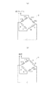
例えば、図1に示すように、レール1を支える枕木2の、隣り合う枕木2の間の中間位置Pcからレール1の敷設方向の前方及び後方に向かってそれぞれ等間隔、例えば0.2m隔てた位置P1,P2で、鉄道車両の車輪3が前記中間位置Pcを通過したときのレールの主応力を測定する。
The present invention has been made based on the above idea of the inventors.
For example, as shown in FIG. 1, the
前記位置P1,P2における主応力の測定は、例えば、図1(b)に示すように、前記敷設方向の前後対称に、かつ、レール1を横断面した場合のレール1の幅方向の中心線CLに対して線対称となるウェブ1aの表裏面に、単軸のひずみゲージ4A1,4B1と4A2,4B2を貼付して行う。
For example, as shown in FIG. 1B, the measurement of the main stress at the positions P1 and P2 is symmetrical in the longitudinal direction of the laying direction and the center line in the width direction of the
図1では、前記ひずみゲージ4A1,4B1と4A2,4B2を輪重作用時の主応力方向に貼付してレール1に発生する主応力を測定する例を示している。その際、前記ひずみゲージ4A1,4B1と4A2,4B2は、それぞれ中間位置Pc方向に例えば45°斜め上向きに貼付している。これは、実作業においては、45°斜め上向きの場合、作業性が良いためである。
FIG. 1 shows an example in which the strain gauges 4A1, 4B1 and 4A2, 4B2 are attached in the principal stress direction during the wheel load action and the principal stress generated in the
また、図1では、このひずみゲージ4A1,4B1と4A2,4B2を、レール1のウェブ1aの高さ方向中心位置付近に貼付している。これは、垂直荷重によってレール1に作用する曲げ応力が小さく、曲げ応力によるノイズの影響を小さくできるからである。
Moreover, in FIG. 1, these strain gauges 4A1, 4B1 and 4A2, 4B2 are affixed in the vicinity of the center position in the height direction of the web 1a of the
また、図1では、鉄道車両の車輪3が前記中間位置Pcを通過したことをレーザ変位計5で検知するものを示している。そして、この車輪3の通過を検知したときに、前記ひずみゲージ4A1,4B1と4A2,4B2によってそれぞれの位置P1,P2におけるレールの主応力を測定し、この測定した主応力を演算器6に入力する。
Further, FIG. 1 shows that the laser displacement meter 5 detects that the wheel 3 of the railway vehicle has passed the intermediate position Pc. When the passage of the wheel 3 is detected, the main stresses of the rails at the respective positions P1 and P2 are measured by the strain gauges 4A1, 4B1, 4A2, and 4B2, and the measured main stress is input to the
この演算器6に入力する主応力は、位置P1と位置P2で測定した主応力の差をとったもので、図2(a)に示すホイートストンブリッジ回路Bを組むことで得ることができる。このように位置P1と位置P2で測定した主応力の差をとることで輪重による主応力が除去され、残った主応力差は縦クリープ力によるものとなる。
The main stress input to the
その理由は、前記中間位置Pcからレール1の敷設方向前後にそれぞれ等間隔隔てた位置P1,P2では、鉄道車両の車輪3が前記中間位置Pcを通過する際の輪重Pは同一である。一方、縦クリープ力Tによるレールひずみは、位置P1と位置P2においてその向き、すなわち符号が異なるからである。
The reason is that at the positions P1 and P2 that are equally spaced from the intermediate position Pc in the longitudinal direction of the
演算器6は、前記縦クリープ力による主応力を、予め求めておいた、輪重Pによってレールに発生する主応力と、縦クリープ力Tによってレールに発生する主応力の関係から換算して縦クリープ力を求める。
The
この輪重Pによってレールに発生する主応力と、縦クリープ力Tによってレールに発生する主応力の関係は、理論解析又はFEM解析により演算しておくことができる。 The relationship between the main stress generated in the rail by the wheel load P and the main stress generated in the rail by the longitudinal creep force T can be calculated by theoretical analysis or FEM analysis.
例えば、位置P1におけるひずみゲージ4A1,4B1が水平線となす敷設方向後側の角度をθ1、位置P1におけるひずみゲージ4A1,4B1から隣り合う枕木2間の中間位置Pcにおけるレール1の頭頂面の車輪3との接触位置までの距離をr1とする。また、位置P2におけるひずみゲージ4A2,4B2が水平線となす敷設方向後側の角度をθ2、位置P2におけるひずみゲージ4A2,4B2から前記接触位置までの距離をr2とする。このようにした場合、位置P1,P2における応力場の式は以下のように表すことができる。
For example, the angle on the rear side in the laying direction between the strain gauges 4A1 and 4B1 at the position P1 and the horizontal line is θ 1 , and the wheel on the top surface of the
(輪重Pによる主応力)
σr=(2P/π)×(sinθ/r)=εP・E
(縦クリープ力Tによる主応力)
σr=(2T/π)×(cosθ/r)=εQ・E
(Main stress due to wheel load P)
σr = (2P / π) × (sinθ / r) = ε P · E
(Main stress due to longitudinal creep force T)
σr = (2T / π) × (cosθ / r) = ε Q · E
すなわち、位置P1では、輪重Pによるひずみ、縦クリープ力Tによるひずみは以下のようになる。
ε1P=(2P/πE)×(sinθ1/r1)=K1・P・sinθ1
ε1Q=(2T/πE)×(cosθ1/r1)=K1・Q・cosθ1
但し、K1=2/πr1E
That is, at the position P1, the strain due to the wheel load P and the strain due to the longitudinal creep force T are as follows.
ε 1P = (2P / πE) × (sin θ 1 / r 1 ) = K 1 · P · sin θ 1
ε 1Q = (2T / πE) × (cos θ 1 / r 1 ) = K 1 · Q · cos θ 1
However, K 1 = 2 / πr 1 E
また、位置P2では、輪重によるひずみ、縦クリープ力によるひずみは以下のようになる。
ε2P=(2P/πE)×(sinθ2/r2)=K2・P・sinθ2
ε2Q=(2T/πE)×(cosθ2/r2)=K2・T・cosθ2
但し、K2=2/πr2E
Further, at the position P2, the strain due to the wheel load and the strain due to the longitudinal creep force are as follows.
ε 2P = (2P / πE) × (sin θ 2 / r 2 ) = K 2 · P · sin θ 2
ε 2Q = (2T / πE) × (cos θ 2 / r 2 ) = K 2 · T · cos θ 2
However, K 2 = 2 / πr 2 E
よって、位置P1,P2にひずみゲージを貼付したときのそれぞれの測定値(主応力)は、下記式で表すことができる。
ε1=K1・P・sinθ1+K1・T・cosθ1
ε2=K2・P・sinθ2+K2・T・cosθ2
Therefore, each measured value (principal stress) when a strain gauge is attached to the positions P1 and P2 can be expressed by the following formula.
ε 1 = K 1 · P · sin θ 1 + K 1 · T · cos θ 1
ε 2 = K 2 · P · sinθ 2 + K 2 · T · cos θ 2
位置P1,P2における測定値を求める式において、r1=r2=r、θ1=θ、θ2=π−θのとき、輪重Pと縦クリープ力Tは、以下の式で求めることができる。
P=(1/Ksinθ)×(ε1+ε2)
T=(1/Kcosθ)×(ε1−ε2)
In the equation for obtaining the measured values at the positions P1 and P2, when r 1 = r 2 = r, θ 1 = θ, θ 2 = π−θ, the wheel load P and the longitudinal creep force T are obtained by the following equations. Can do.
P = (1 / Ksinθ) × (ε 1 + ε 2 )
T = (1 / Kcosθ) × (ε 1 −ε 2 )
従って、上記した式により、輪重Pによる主応力と、縦クリープ力Tによる主応力の関係を、予め求めておくことができる。 Therefore, the relationship between the main stress caused by the wheel load P and the main stress caused by the longitudinal creep force T can be obtained in advance by the above formula.
この輪重Pと縦クリープ力Tによる主応力の関係は、縦クリープ力による主応力を縦クリープ力に換算するだけでなく、図2(b)に示すホイートストンブリッジ回路Bに変更することで、現場で輪重を較正して縦クリープ力を現場で較正することもできる。 The relationship between the main stress caused by the wheel load P and the longitudinal creep force T is not only converted from the principal stress caused by the longitudinal creep force into the longitudinal creep force, but also changed to the Wheatstone bridge circuit B shown in FIG. It is also possible to calibrate the wheel load on site and calibrate the longitudinal creep force on site.
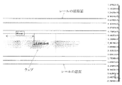
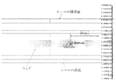
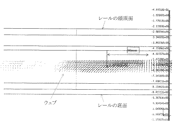
図3〜図6は30kNの輪重を作用させたときのレールに発生する主応力をFEM解析した結果を示した図である。このFEM解析に使用したレールは、50kgNレールで、道床のヤング率はコンクリート直結道床を想定して19600MPaとし、レールのヤング率は206GPaとした。 3 to 6 are diagrams showing the results of FEM analysis of the main stress generated in the rail when a wheel load of 30 kN is applied. The rail used for this FEM analysis was a 50 kgN rail, and the Young's modulus of the roadbed was 19600 MPa assuming a concrete directly connected roadbed, and the Young's modulus of the rail was 206 GPa.
前記条件で行ったFEM解析によれば、主応力が45°の方向となるのは、図3〜図6に示したように、荷重点から前後方向に90mmの点であった。 According to the FEM analysis performed under the above conditions, the principal stress is in the direction of 45 °, as shown in FIGS. 3 to 6, at a point 90 mm in the front-rear direction from the load point.
道床をバラスト道床と想定し、ヤング率を27.9〜47.9MPaとして同様のFEM解析を行ったところ、荷重点から前後方向に85〜120mmの範囲で主応力がほぼ45°の方向となった。 Assuming that the roadbed is a ballast roadbed, the same FEM analysis was performed with a Young's modulus of 27.9-47.9 MPa, and the principal stress was in the direction of 45 ° in the range of 85-120 mm from the load point to the front-back direction. It was.
このFEM解析の結果より、位置P1,P2は、中間位置Pcからレールの敷設方向前後にそれぞれ85〜120mmの範囲内に設定することが望ましいことがわかる。 From the results of this FEM analysis, it is understood that the positions P1 and P2 are preferably set within a range of 85 to 120 mm before and after the intermediate position Pc in the rail laying direction.
また、下記表1は、図1に示したように、位置P1と位置P2において前後対称に、中間位置Pcに向けて45°上向き方向にひずみゲージを貼付し、中間位置Pcに以下の荷重を作用させたときの45°方向の主応力を示したものである。 Further, as shown in FIG. 1, the following Table 1 shows that a strain gauge is attached in a 45 ° upward direction toward the intermediate position Pc symmetrically in the longitudinal direction at the positions P1 and P2, and the following loads are applied to the intermediate position Pc. The principal stress in the 45 ° direction when applied is shown.
(作用させた荷重)
・30kNの輪重
・10kNの縦クリープ力
・30kNの輪重と10kNの縦クリープ力の合成荷重
(Load applied)
・ 30kN wheel load ・ 10kN longitudinal creep force ・ Combined load of 30kN wheel load and 10kN longitudinal creep force
上記表1より、30kNの輪重と10kNの縦クリープ力の合成荷重を作用させた時の、位置P1と位置P2の平均は−10.75MPaで、位置P1と位置P2の差は3.5MPaである。これらの値は、それぞれ30kNの輪重を作用させた場合と10kNの縦クリープ力を作用させた場合の主応力に対応していることがわかる。 From Table 1 above, when a combined load of 30 kN wheel load and 10 kN longitudinal creep force is applied, the average of position P1 and position P2 is −10.75 MPa, and the difference between position P1 and position P2 is 3.5 MPa. It is. It can be seen that these values correspond to principal stresses when a wheel load of 30 kN is applied and when a longitudinal creep force of 10 kN is applied, respectively.
本発明は上記の例に限らず、各請求項に記載された技術的思想の範疇であれば、適宜実施の形態を変更しても良いことは言うまでもない。 The present invention is not limited to the above example, and it goes without saying that the embodiments may be changed as appropriate within the scope of the technical idea described in each claim.
上記の実施例では単軸のひずみゲージを用いて主応力を測定しているが、2軸のひずみゲージや3軸のひずみゲージを用いて主応力を測定してもよい。2軸のひずみゲージや3軸のひずみゲージを採用する場合、測定出力から主応力を求めてもよいし、位置P1,P2に貼付するひずみゲージの位置を主応力向きになるように調整し、単軸のひずみゲージとして使用してもよい。 In the above embodiment, the principal stress is measured using a uniaxial strain gauge, but the principal stress may be measured using a biaxial strain gauge or a triaxial strain gauge. When a biaxial strain gauge or a triaxial strain gauge is adopted, the main stress may be obtained from the measurement output, or the position of the strain gauge applied to the positions P1 and P2 is adjusted so as to be directed to the principal stress. It may be used as a uniaxial strain gauge.
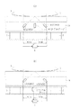
また、鉄道車両の車輪3が中間位置Pcを通過したことの検知はレーザ変位計5に限らず、図7に示すように、隣り合う枕木間の中間位置のレール1にひずみゲージ4Cを貼付し、測定応力のピーク値で車輪の通過を検知してもよい。この場合、ひずみゲージ4Cは、図7(a)に示すように、レール1のウェブ1aの高さ方向中心位置に高さ方向に貼付しても、図7(b)に示すように、レール1の底面にレール1の敷設方向に貼付してもよい。
Further, the detection that the wheel 3 of the railway vehicle has passed the intermediate position Pc is not limited to the laser displacement meter 5, but a strain gauge 4C is attached to the
また、上記の実施例では、主応力を測定して縦クリープ力を得ているが、主ひずみから縦クリープ力を得るようにしてもよい。 In the above embodiment, the main stress is measured to obtain the longitudinal creep force. However, the longitudinal creep force may be obtained from the main strain.
また、上記の実施例では、ひずみゲージを用いて主応力を測定しているが、主応力又は主ひずみを測定できるものであれば、光ファイバーセンサーや表面弾性波センサー等、ひずみゲージ以外の測定子を使用してもよい。 In the above embodiment, the principal stress is measured using a strain gauge. However, if the principal stress or principal strain can be measured, a probe other than the strain gauge, such as an optical fiber sensor or a surface acoustic wave sensor. May be used.
また、本発明を用いて曲線区間走行中の縦クリープ力を地上から測定することで、レール上を走行する車両の車輪の踏面摩耗をモニタリングすることもできる。 Further, by measuring the vertical creep force during traveling in a curved section from the ground using the present invention, it is possible to monitor the tread wear on the wheels of the vehicle traveling on the rail.
また、本発明を用いて直線区間走行中の縦クリープ力を地上から測定することで、走行する車両の軸箱の前後指示状態をモニタリングすることもできる。 Further, by measuring the longitudinal creep force during traveling in a straight section from the ground using the present invention, it is possible to monitor the front-rear instruction state of the axle box of the traveling vehicle.
1 レール
2 枕木
3 車輪
4A1,4B1,4A2,4B2 ひずみゲージ
4C ひずみゲージ
5 レーザ変位計
6 演算器
Pc 中間位置
P1 敷設方向前方の位置
P2 敷設方向後方の位置
B ホイートストンブリッジ回路
P 輪重
T 縦クリープ力
CL レールの幅方向中心線
1
Claims (14)
これら測定した2か所における前記主応力又は主ひずみの差を、理論解析又は有限要素解析により事前に求めておいた、輪重により発生する主応力又は主ひずみと、縦クリープ力により発生する主応力又は主ひずみの関係に基づき、縦クリープ力に換算することを特徴とする鉄道車両の車輪とレール間の縦クリープ力測定方法。 The main stress generated in the rail when the wheel of the railroad vehicle passes through the intermediate position at two locations that are equidistant from each other in the longitudinal direction of the rail, from the intermediate position between adjacent sleepers that support the rail, or Measure the main strain,
The difference between the principal stress or the principal strain at these two measured locations is determined in advance by theoretical analysis or finite element analysis, and the principal stress or principal strain generated by the wheel load and the principal stress generated by the longitudinal creep force. A method of measuring a longitudinal creep force between a wheel and a rail of a railway vehicle, wherein the longitudinal creep force is converted based on a relationship between stress or principal strain.
鉄道車両の車輪が、前記中間位置を通過することを検知する手段と、
前記車輪が前記中間位置を通過したときに、前記測定子によって測定した、前後2か所の測定位置における主応力又は主ひずみの平均と差をとることで、前記主応力又は主ひずみの平均である輪重による主応力又は主ひずみと、前記主応力又は主ひずみの差である縦クリープ力による主応力又は主ひずみに分離し、この分離した縦クリープ力による主応力又は主ひずみを、予め求めておいた輪重により発生する主応力又は主ひずみと、縦クリープ力により発生する主応力又は主ひずみの関係から換算して縦クリープ力を得る演算器と、
を備えたことを特徴とする鉄道車両の車輪とレール間の縦クリープ力測定装置。 A measuring element that measures the main stress or main strain of the rail symmetrically in the longitudinal direction of the rail in two locations that are equally spaced in the longitudinal direction of the rail from the intermediate position between adjacent sleepers that support the rail; and
Means for detecting that a wheel of the railway vehicle passes through the intermediate position;
When the wheel passes the intermediate position, the average of the principal stress or principal strain is obtained by taking the difference from the mean principal stress or principal strain at the two measurement positions before and after the measurement by the probe. The main stress or main strain due to a certain wheel load is separated into the main stress or main strain due to the longitudinal creep force that is the difference between the main stress or main strain, and the main stress or main strain due to the separated vertical creep force is obtained in advance. An arithmetic unit that obtains a longitudinal creep force in terms of the relationship between the principal stress or principal strain generated by the wheel load and the principal stress or principal strain generated by the longitudinal creep force;
A device for measuring a longitudinal creep force between a wheel and a rail of a railway vehicle.
Priority Applications (1)
| Application Number | Priority Date | Filing Date | Title |
|---|---|---|---|
| JP2016063528A JP6663267B2 (en) | 2016-03-28 | 2016-03-28 | Method and apparatus for measuring longitudinal creep force between wheel and rail of railway vehicle |
Applications Claiming Priority (1)
| Application Number | Priority Date | Filing Date | Title |
|---|---|---|---|
| JP2016063528A JP6663267B2 (en) | 2016-03-28 | 2016-03-28 | Method and apparatus for measuring longitudinal creep force between wheel and rail of railway vehicle |
Publications (2)
| Publication Number | Publication Date |
|---|---|
| JP2017181061A true JP2017181061A (en) | 2017-10-05 |
| JP6663267B2 JP6663267B2 (en) | 2020-03-11 |
Family
ID=60006912
Family Applications (1)
| Application Number | Title | Priority Date | Filing Date |
|---|---|---|---|
| JP2016063528A Active JP6663267B2 (en) | 2016-03-28 | 2016-03-28 | Method and apparatus for measuring longitudinal creep force between wheel and rail of railway vehicle |
Country Status (1)
| Country | Link |
|---|---|
| JP (1) | JP6663267B2 (en) |
Cited By (5)
| Publication number | Priority date | Publication date | Assignee | Title |
|---|---|---|---|---|
| CN108491594A (en) * | 2018-03-08 | 2018-09-04 | 大连交通大学 | A method of based on trackside arrangement foil gauge gathered data reverse wheel and rail intermolecular forces |
| CN109752129A (en) * | 2018-11-30 | 2019-05-14 | 宝鸡欧亚化工设备制造厂 | A kind of multi-drive system titanium alloy track stress detection device |
| CN110595996A (en) * | 2019-09-18 | 2019-12-20 | 西南交通大学 | Wheel rail adhesion creep and slide measuring instrument on linear rail |
| CN114088290A (en) * | 2021-11-19 | 2022-02-25 | 中车长春轨道客车股份有限公司 | Steel rail assembly for calibrating force measuring wheel set and force measuring wheel set calibration test bed |
| CN114894138A (en) * | 2022-06-14 | 2022-08-12 | 广汽本田汽车有限公司 | Method, system, equipment and storage medium for detecting vertical displacement difference of automobile wheel |
Families Citing this family (1)
| Publication number | Priority date | Publication date | Assignee | Title |
|---|---|---|---|---|
| RU2755595C1 (en) * | 2021-02-12 | 2021-09-17 | Акционерное общество "Научно-исследовательский и конструкторско-технологический институт подвижного состава" (АО "ВНИКТИ") | Stand for the study of the stress state of rails, defects of rails and rolling stock wheels |
Citations (3)
| Publication number | Priority date | Publication date | Assignee | Title |
|---|---|---|---|---|
| JPH10185666A (en) * | 1996-12-25 | 1998-07-14 | Unyusho Senpaku Gijutsu Kenkyusho | Method and device for continuously measuring wheel load and lateral force of rolling stock with ground side measurement |
| JP2002357492A (en) * | 2001-06-04 | 2002-12-13 | Yamato Scale Co Ltd | Load cell, and load detecting gauge |
| WO2015110361A2 (en) * | 2014-01-21 | 2015-07-30 | fos4X GmbH | Rail measuring system |
-
2016
- 2016-03-28 JP JP2016063528A patent/JP6663267B2/en active Active
Patent Citations (3)
| Publication number | Priority date | Publication date | Assignee | Title |
|---|---|---|---|---|
| JPH10185666A (en) * | 1996-12-25 | 1998-07-14 | Unyusho Senpaku Gijutsu Kenkyusho | Method and device for continuously measuring wheel load and lateral force of rolling stock with ground side measurement |
| JP2002357492A (en) * | 2001-06-04 | 2002-12-13 | Yamato Scale Co Ltd | Load cell, and load detecting gauge |
| WO2015110361A2 (en) * | 2014-01-21 | 2015-07-30 | fos4X GmbH | Rail measuring system |
Cited By (9)
| Publication number | Priority date | Publication date | Assignee | Title |
|---|---|---|---|---|
| CN108491594A (en) * | 2018-03-08 | 2018-09-04 | 大连交通大学 | A method of based on trackside arrangement foil gauge gathered data reverse wheel and rail intermolecular forces |
| CN108491594B (en) * | 2018-03-08 | 2022-03-29 | 大连交通大学 | Method for reversely solving acting force between wheel and steel rail based on data acquired by strain gauge arranged on rail side |
| CN109752129A (en) * | 2018-11-30 | 2019-05-14 | 宝鸡欧亚化工设备制造厂 | A kind of multi-drive system titanium alloy track stress detection device |
| CN110595996A (en) * | 2019-09-18 | 2019-12-20 | 西南交通大学 | Wheel rail adhesion creep and slide measuring instrument on linear rail |
| CN110595996B (en) * | 2019-09-18 | 2020-06-16 | 西南交通大学 | Wheel rail adhesion creep and slide measuring instrument on linear rail |
| CN114088290A (en) * | 2021-11-19 | 2022-02-25 | 中车长春轨道客车股份有限公司 | Steel rail assembly for calibrating force measuring wheel set and force measuring wheel set calibration test bed |
| CN114088290B (en) * | 2021-11-19 | 2024-03-08 | 中车长春轨道客车股份有限公司 | Steel rail assembly for measuring force wheel set calibration and measuring force wheel set calibration test bed |
| CN114894138A (en) * | 2022-06-14 | 2022-08-12 | 广汽本田汽车有限公司 | Method, system, equipment and storage medium for detecting vertical displacement difference of automobile wheel |
| CN114894138B (en) * | 2022-06-14 | 2023-06-30 | 广汽本田汽车有限公司 | Method, system, equipment and storage medium for detecting vertical displacement difference of automobile wheel |
Also Published As
| Publication number | Publication date |
|---|---|
| JP6663267B2 (en) | 2020-03-11 |
Similar Documents
| Publication | Publication Date | Title |
|---|---|---|
| JP6663267B2 (en) | Method and apparatus for measuring longitudinal creep force between wheel and rail of railway vehicle | |
| US10392035B2 (en) | Method and apparatus to determine structural parameters of a railway track | |
| CN110446913A (en) | For detecting and/or the device and method of calibration test platform | |
| KR20120009729A (en) | Apparatus for loading test of railroad bridge, method for calculating load carrying capacity of railroad bridge and method for measuring drooping of railroad bridge | |
| KR101827485B1 (en) | Trolly apparatus for measuring track irregularity having track guidance member of hydraulic type, and method for the same | |
| Urda et al. | Wheel-rail contact force measurement using strain gauges and distance lasers on a scaled railway vehicle | |
| O’Brien et al. | Strategies for axle detection in bridge weigh-in-motion systems | |
| JP4759744B2 (en) | Method for detecting contact position between railroad vehicle wheel and rail | |
| JP2020502401A (en) | Inspection apparatus and method for detecting track shape | |
| CN104006978A (en) | Method for indirectly measuring acting force between railway vehicle wheel tracks | |
| Zhang et al. | Design, calibration and validation of a wheel-rail contact force measurement system in V-Track | |
| Zhou et al. | A new wayside method for measuring and evaluating wheel-rail contact forces and positions | |
| JP2003166870A (en) | Axle load measuring method of vehicle running on bridge | |
| Molatefi et al. | Analysis of new method for vertical load measurement in the barycenter of the rail web by using FEM | |
| JP2006088967A (en) | Horizontal pressure measurement method and truck for railway vehicle | |
| CN106004928B (en) | Track seam transversion malposition detection means and method | |
| JP2008233062A (en) | Method of measuring tangential force and wheel load which interact between railway vehicle wheel and rail and method of measuring axle torsion | |
| CN208915183U (en) | Rail bottom formula shear force sensor applied to railway detection, metering | |
| JP4814121B2 (en) | Measuring method of wheel load or lateral pressure | |
| Rakoczy et al. | Railroad bridge condition evaluation using onboard systems | |
| KR101533226B1 (en) | Slab track twist monitoring apparatus | |
| CN106706192B (en) | Rail bottom bending moment type force sensor | |
| RU2656777C2 (en) | Control method of the jointless railway track | |
| JP6944847B2 (en) | Lateral pressure measurement method using axles | |
| RU2411464C1 (en) | Method of weighing railroad vehicles |
Legal Events
| Date | Code | Title | Description |
|---|---|---|---|
| A621 | Written request for application examination |
Free format text: JAPANESE INTERMEDIATE CODE: A621 Effective date: 20190214 |
|
| A977 | Report on retrieval |
Free format text: JAPANESE INTERMEDIATE CODE: A971007 Effective date: 20191113 |
|
| A131 | Notification of reasons for refusal |
Free format text: JAPANESE INTERMEDIATE CODE: A131 Effective date: 20191119 |
|
| A521 | Request for written amendment filed |
Free format text: JAPANESE INTERMEDIATE CODE: A523 Effective date: 20191226 |
|
| TRDD | Decision of grant or rejection written | ||
| A01 | Written decision to grant a patent or to grant a registration (utility model) |
Free format text: JAPANESE INTERMEDIATE CODE: A01 Effective date: 20200121 |
|
| A61 | First payment of annual fees (during grant procedure) |
Free format text: JAPANESE INTERMEDIATE CODE: A61 Effective date: 20200214 |
|
| R150 | Certificate of patent or registration of utility model |
Ref document number: 6663267 Country of ref document: JP Free format text: JAPANESE INTERMEDIATE CODE: R150 |
|
| R250 | Receipt of annual fees |
Free format text: JAPANESE INTERMEDIATE CODE: R250 |
|
| R250 | Receipt of annual fees |
Free format text: JAPANESE INTERMEDIATE CODE: R250 |