JP2017178172A - Drive support method and drive support apparatus - Google Patents
Drive support method and drive support apparatus Download PDFInfo
- Publication number
- JP2017178172A JP2017178172A JP2016071248A JP2016071248A JP2017178172A JP 2017178172 A JP2017178172 A JP 2017178172A JP 2016071248 A JP2016071248 A JP 2016071248A JP 2016071248 A JP2016071248 A JP 2016071248A JP 2017178172 A JP2017178172 A JP 2017178172A
- Authority
- JP
- Japan
- Prior art keywords
- preceding vehicle
- vehicle
- occupant
- driving support
- behavior
- Prior art date
- Legal status (The legal status is an assumption and is not a legal conclusion. Google has not performed a legal analysis and makes no representation as to the accuracy of the status listed.)
- Pending
Links
Images


Abstract
Description
本発明は、運転支援方法、及び運転支援装置に関する。 The present invention relates to a driving support method and a driving support device.
特許文献1には、ドアミラーの周囲にインジケータを設置し、車両の周囲に障害物が存在することが検出された際に、インジケータを点灯させることにより、障害物を認識させる技術が開示されている。 Patent Document 1 discloses a technique for recognizing an obstacle by installing an indicator around a door mirror and turning on the indicator when it is detected that an obstacle exists around the vehicle. .
しかしながら、上述した特許文献1に開示された従来例は、インジケータの点灯により障害物の存在を乗員に知らせるものであり、乗員がドアミラーに見入っているときに、自車両の前方を走行する先行車両の接近、或いは先行車両の車線変更等の挙動を乗員に知らせるものではなかった。 However, the above-described conventional example disclosed in Patent Document 1 notifies the occupant of the presence of an obstacle by turning on an indicator. When the occupant looks into the door mirror, the preceding vehicle travels ahead of the host vehicle. It was not intended to inform the occupants of the behavior of the approaching vehicle or the lane change of the preceding vehicle.
本発明は、このような従来の課題を解決するためになされたものであり、その目的とするところは、乗員が表示部に見入っている場合でも、先行車両が接近或いは車線変更した際に乗員の注意を自車両の前方に向けさせることができる運転支援方法、及び運転支援装置を提供することにある。 The present invention has been made in order to solve such a conventional problem. The object of the present invention is to provide an occupant when a preceding vehicle approaches or changes lanes even when the occupant is looking at the display unit. It is an object to provide a driving support method and a driving support device that can direct the attention of the vehicle toward the front of the host vehicle.
上記目的を達成するため、本発明の一態様は、後方画像を表示する表示部にインジケータを設け、自車両の前方を走行する先行車両の挙動を検出する。そして、先行車両の挙動に応じて、表示部の上縁部、及び下縁部のうち、乗員のアイポイントの高さに近い方の縁部に設けたインジケータを明灯させる。 In order to achieve the above object, according to one embodiment of the present invention, an indicator is provided on a display unit that displays a rear image, and the behavior of a preceding vehicle that travels ahead of the host vehicle is detected. Then, according to the behavior of the preceding vehicle, an indicator provided on the edge closer to the height of the occupant's eye point among the upper edge and the lower edge of the display section is lit.
本発明の一態様によれば、自車両の乗員が表示部に見入っている場合でも、先行車両の挙動に応じて表示部の上縁部或いは下縁部が明灯するので、乗員の注意を自車両の前方に向けさせることができる。 According to one aspect of the present invention, even when an occupant of the host vehicle is looking into the display unit, the upper or lower edge of the display unit is lit according to the behavior of the preceding vehicle. It can be directed to the front of the vehicle.
[第1実施形態の説明]
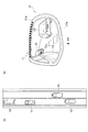
以下、本発明の実施形態を図面に基づいて説明する。図1は、本発明の第1実施形態に係る運転支援装置の構成を示すブロック図、図2は、自車両に搭載される右側のドアミラーを示す説明図である。図1に示すように、第1実施形態に係る運転支援装置101は、車両のドアミラー21(図2参照)の上縁部に設けられた複数のLED11(インジケータ)と、自車両の前方を走行する先行車両を捕捉するLRF12(Laser Range Finder)と、該LRF12で捕捉される先行車両を検出する先行車両検出回路13と、先行車両の減速を検出する先行車両減速検出回路14と、先行車両が自車両に接近する状況に基づいて、LED11の点灯(明灯)を制御する点灯制御回路16(明灯制御回路)と、を備えている。
[Description of First Embodiment]
Hereinafter, embodiments of the present invention will be described with reference to the drawings. FIG. 1 is a block diagram showing the configuration of the driving assistance apparatus according to the first embodiment of the present invention, and FIG. 2 is an explanatory view showing a right door mirror mounted on the host vehicle. As shown in FIG. 1, the
LRF12は、周知のように赤外線レーザを発振して目標物に照射し、この反射の度合いから目標となる物体までの距離を測定する光学機器であり、先行車両と自車両との間の車間距離、及び、先行車両の横方向の動きを検出することができる。なお、本実施形態では、LRF12を用いて先行車両の挙動を検出する例について説明するが、本発明はこれに限定されず、カメラ、ミリ波レーダ、電波レーダ、音波レーダ、マイクロ波レーダ、車々間通信、路車間通信を用いて、先行車両の挙動を検出することも可能である。
As is well known, the LRF 12 is an optical device that irradiates a target by oscillating an infrared laser and measures the distance to the target object from the degree of reflection, and the inter-vehicle distance between the preceding vehicle and the host vehicle. , And the lateral movement of the preceding vehicle can be detected. In this embodiment, an example in which the behavior of the preceding vehicle is detected using the
先行車両検出回路13は、LRF12による検出データに基づいて、自車両の前方を走行する先行車両の存在を検出する。
The preceding
先行車両減速検出回路14は、LRF12による検出データに基づいて、自車両と先行車両との間の車間距離を検出し、車間距離が減少していると判断した場合には、先行車両が減速しているものと判断する。また、先行車両のブレーキランプの点灯状態により減速を検出し、先行車両のウインカーの点灯状態により車線変更方向を検出するようにすることも可能である。
The preceding vehicle
LED11は、図2に示すように、ドアミラー21(表示部)の上縁部21aに複数設けられている。ドアミラー21は、自車両の乗員のアイポイントよりも低い位置に設置される。従って、ドアミラー21の下縁部21bよりも上縁部21aの方が乗員のアイポイントの高さに近い位置となる。よって、本実施形態では、ドアミラー21の上縁部21aに複数のLED11を設けている。
As shown in FIG. 2, a plurality of
点灯制御回路16は、先行車両の挙動に基づいてLED11の点灯を制御する。具体的には、先行車両が減速している場合(車間距離が減少している場合)に、LED11を点灯させることにより、自車両の乗員に対して前方への注意を喚起する。LED11の点灯色は、乗員の注意を喚起する効果を高めるため赤色が好ましい。また、点灯制御回路16には、自車両のウインカー操作信号が入力される。そして、後述するように、ウインカーが操作されているときにLED11の点灯制御を実施する。
The
ここで、先行車両検出回路13、先行車両減速検出回路14、及び点灯制御回路16は、例えば、中央演算ユニット(CPU)や、RAM、ROM、ハードディスク等の記憶手段からなる一体型のコンピュータとして構成することができる。
Here, the preceding
次に、上述のように構成された第1実施形態に係る運転支援装置101の作用を、図3に示すフローチャートを参照して説明する。初めに、ステップS11において、点灯制御回路16は、ウインカー操作信号が入力されたか否かに基づき、自車両のウインカーがオンとされているか否かを判断する。
Next, the operation of the driving
ステップS12において、先行車両検出回路13は、LRF12での検出データに基づき、自車両の走行車線の前方を走行する先行車両の有無を検出する。ステップS13において、先行車両検出回路13は、先行車両が存在するか否かを判断し、先行車両が存在する場合には、ステップS14において、先行車両と自車両との間の車間距離の変化を監視する。
In step S <b> 12, the preceding
ステップS15において、先行車両減速検出回路14は、車間距離が短くなっているか否かを判断する。即ち、自車両が先行車両に接近しつつあるか否かを判断する。例えば、先行車両がブレーキを作動させている場合には、車間距離が短くなるので接近しつつあるものと判断する。
In step S15, the preceding vehicle
車間距離が短くなっていると判断された場合には(ステップS15でYES)、ステップS16において、点灯制御回路16はドアミラー21の上縁部21aに設けたLED11を点灯させる。従って、ウインカーを操作して車線変更しようとする乗員がドアミラー21に見入っている際に、先行車両との間の車間距離が短くなった場合に、ドアミラー21の上縁部21aに設けられた複数のLED11が点灯するので、乗員は自車両の前方に注意を向けることができる。
If it is determined that the inter-vehicle distance is short (YES in step S15), the
ステップS17において、先行車両減速検出回路14は、車間距離が長くなっているか否かを判断する。車間距離が長くなっている場合には(ステップS17でYES)、ステップS18において、点灯制御回路16はLED11を消灯する。
In step S17, the preceding vehicle
ステップS19において、点灯制御回路16は、ウインカーがオフであるか否かを判断し、オフである場合には(ステップS19でYES)、本処理を終了する。
In step S19, the
次に、上述した動作を、図4に示す説明図を参照して説明する。図4(a)は、自車両V1が左側車線を走行し、更に、自車両V1の前方に先行車両V4が存在し、後方に他車両V2が存在し、右側車線の自車両後方に他車両V3が存在する状況を示している。 Next, the operation described above will be described with reference to the explanatory diagram shown in FIG. FIG. 4A shows that the host vehicle V1 travels in the left lane, the preceding vehicle V4 is present in front of the host vehicle V1, the other vehicle V2 is present behind, and the other vehicle is located behind the host vehicle in the right lane. The situation where V3 exists is shown.
このような状況下で、自車両V1が右側車線に車線変更する場合には、右方向のウインカーを点灯させ、且つ、乗員は右側のドアミラー21を注視する。図4(b)は、右側のドアミラー21、及び該ドアミラー21に表示される後方像を示している。図4(b)に示すように、ドアミラー21には他車両V2、V3が表示されており、乗員はこの後方像を見ながら車線変更を実施する。
Under such circumstances, when the host vehicle V1 changes lanes to the right lane, the right turn signal is turned on, and the occupant gazes at the
この際、先行車両V4がブレーキ操作すると、自車両V1と先行車両V4との間の車間距離が短くなり、図3のステップS16の処理によりLED11が点灯する。自車両V1の乗員は、LED11が点灯することにより、車間距離が短くなっていることをいち早く認識することができ、先行車両V4に注意を向けることができる。こうして、車間距離が短くなった際に、乗員の注意を前方に向けることができることになる。
At this time, when the preceding vehicle V4 performs a brake operation, the inter-vehicle distance between the host vehicle V1 and the preceding vehicle V4 is shortened, and the
このようにして、第1実施形態に係る運転支援装置101では、LRF12により自車両前方を走行する先行車両V4を検出し、更に、該先行車両V4との間の車間距離が短くなった場合には、ドアミラー21の上縁部21aを明灯させる。従って、自車両V1の乗員に対し車間距離が短くなったことに即時に気づかせることができ、自車両V1の前方に注意を向けさせることができる。また、上縁部21aに設置した複数のLED11等のインジケータを点灯(明灯)させるので、車間距離が短くなったことを認識し易い態様で乗員に気づかせることができ、自車両V1の前方に注意を向けさせることができる。その結果、車線変更時等の状況下において、後方確認のためにドアミラー21に見入っている場合でも、乗員は自車両V1の前方に視線を移し、減速操作等の対応を採ることが可能となる。
In this way, the driving
また、ドアミラー21の上縁部21a、及び下縁部21bのうち、乗員のアイポイントの高さに近い方である上縁部21aにLED11を設けているので、LED11が点灯した場合には、そのまま上方に視線を移動させ、自然な動きで自車両の前方を視認することができる。
Moreover, since LED11 is provided in the
なお、上述した第1実施形態では、ドアミラー21に設けるインジケータとして、LED11を用いる例について説明したが、本発明はこれに限定されるものではなく、蛍光管等の他のインジケータを用いることも可能である。
In the first embodiment described above, the example in which the
また、上述した実施形態では、ドアミラー21が乗員のアイポイントよりも低い位置に設けられることを前提として、ドアミラー21の上縁部21aにLED11を設ける例、即ち、より乗員のアイポイントに近い位置にある上縁部21aにLED11設けて、該LED11を点灯させる例について説明した。これに対して、例えば、バスやトラック等の車両は、ドアミラーが乗員のアイポイントよりも高い位置に存在することがある。
Moreover, in embodiment mentioned above, on the assumption that the
このような場合には、乗員のアイポイントの高さに近い方である、ドアミラーの下縁部にLED等のインジケータを配置する。こうすることにより、インジケータが点灯(明灯)した場合は、乗員は視線を下方に移動することになり、乗員の視線を自然な動きで自車両の前方を向くように誘導することが可能となる。即ち、本実施形態では、表示部(ドアミラー21)の上縁部、及び下縁部のうち、乗員のアイポイントの高さに近い方の縁部を明灯させることにより、乗員の視線を自然な動きで前方に向けさせ、先行車両が接近していることを認識させることが可能となる。 In such a case, an indicator such as an LED is disposed on the lower edge of the door mirror, which is closer to the height of the passenger's eye point. By doing so, when the indicator is lit (bright), the occupant moves the line of sight downward, and can guide the occupant's line of sight toward the front of the host vehicle with natural movement. . In other words, in the present embodiment, among the upper edge portion and the lower edge portion of the display unit (door mirror 21), the edge portion closer to the height of the passenger's eye point is brightly lit, so that the occupant's line of sight is natural. It is possible to recognize that the preceding vehicle is approaching by moving it forward.
また、上述した第1実施形態では、ウインカーがオンとされていることを条件として、LED11の点灯を制御する例について説明したが、本発明はこれに限定されるものではなく、ウインカーの操作に関係なく先行車両V4の接近が検出された際に、LED11を点灯させるようにしてもよい。即ち、図3に示したステップS11、S19の処理を実施しなくてもよい。
Moreover, in 1st Embodiment mentioned above, although the example which controls lighting of LED11 on the condition that the turn signal is turned on was demonstrated, this invention is not limited to this, It is for operation of a turn signal. Regardless of when the approach of the preceding vehicle V4 is detected, the
更に、第1実施形態では、LRF12の検出データに基づいて先行車両V4と自車両V1との車間距離を測定する例について説明したが、例えば、自車両V1の前方にカメラを搭載し、該カメラで先行車両V4を撮像し、撮像した画像に含まれるブレーキランプの点灯状態に応じて先行車両の接近を検出するようにしてもよい。具体的には、先行車両V4のブレーキランプが点灯した場合には、先行車両V4が接近中であると判断することも可能である。
Further, in the first embodiment, the example in which the inter-vehicle distance between the preceding vehicle V4 and the host vehicle V1 is measured based on the detection data of the
[第1実施形態の第1変形例の説明]
次に、前述した第1実施形態の第1変形例について説明する。前述した第1実施形態では、図3のステップS15において、車間距離が短くなっているか否かを判断し、短くなっている場合には、LED11を点灯させる例について説明した。更に、ステップS17において、車間距離が長くなっているか否かを判断し、長くなっている場合には、LED11を消灯させた。
[Description of First Modification of First Embodiment]
Next, a first modification of the above-described first embodiment will be described. In the first embodiment described above, an example in which it is determined in step S15 of FIG. 3 whether or not the inter-vehicle distance is shortened, and when it is shortened, the
これに対して第1変形例では、リスク度が高まる車間距離を第1車間距離として設定し、更に、第1車間距離よりも長い第2車間距離を設定する。そして、図3のステップS15の処理において、車間距離が第1車間距離以下になったか否かを判定し、第1車間距離以下になった場合に、LED11を点灯させる。
On the other hand, in the first modification, the inter-vehicle distance that increases the degree of risk is set as the first inter-vehicle distance, and further, the second inter-vehicle distance that is longer than the first inter-vehicle distance is set. Then, in the process of step S15 in FIG. 3, it is determined whether or not the inter-vehicle distance is equal to or less than the first inter-vehicle distance. When the inter-vehicle distance is equal to or less than the first inter-vehicle distance, the
更に、ステップS17の処理において、車間距離が第2車間距離以上になったか否かを判定し、第2車間距離以上になった場合に、LED11を消灯させる。このような構成においても、前述した第1実施形態と同様に、乗員がドアミラー21に見入っている場合でも、該乗員に対して先行車両の接近を即時に認識させることができ、乗員の視線を前方に向けさせることが可能となる。
Furthermore, in the process of step S17, it is determined whether or not the inter-vehicle distance is equal to or greater than the second inter-vehicle distance. If the inter-vehicle distance is equal to or greater than the second inter-vehicle distance, the
[第1実施形態の第2変形例の説明]
前述した第1実施形態では、図2に示したように、ドアミラー21の上縁部21aにLED11を配設し、LED11の点灯、消灯を切り替える構成とした。第2変形例では、ルームミラーに適用した場合について説明する。
[Description of Second Modification of First Embodiment]
In the first embodiment described above, as shown in FIG. 2, the
即ち、ルームミラーは、通常乗員のアイポイントよりも高い位置に存在するので、上縁部、及び下縁部のうちのアイポイントの高さに近い方である下縁部にLED11を設ける。図5は、車両内部に設けられるルームミラーを示す説明図である。図5に示すように、ルームミラー33は略矩形状をなしており、該ルームミラー33の下縁部33bに複数のLED11を配設している、そして、先行車両と自車両との間の車間距離が短くなった場合に、複数のLED11を点灯させる。
That is, since the room mirror is usually present at a position higher than the eye point of the occupant, the
その結果、自車両の乗員は、ルームミラー33に見入っている場合でも、即時に視線を下方に移動させて、前方を注視することができる。即ち、乗員のアイポイントの高さに近い方の縁部である下縁部33bを点灯させることにより、自然な動きで乗員の視線を下方に誘導して先行車両を注視させることができる。LED11の点灯、消灯の制御は、前述した第1実施形態と同様であるので、説明を省略する。
As a result, even if the occupant of the host vehicle is looking into the
[第2実施形態の説明]
次に、本発明の第2実施形態について説明する。図6は、第2実施形態に係る運転支援装置102の構成を示すブロック図である。図6に示す運転支援装置102は、図1に示した運転支援装置101と対比して、車線変更方向検出回路15を備えている点で相違する。
[Description of Second Embodiment]
Next, a second embodiment of the present invention will be described. FIG. 6 is a block diagram illustrating a configuration of the driving
更に、点灯制御回路16にウインカー操作信号が入力されていない点で相違する。更に、点灯制御回路16は先行車両との間の車間距離に加え、先行車両の左右方向に動きに基づいてLED11の点灯を制御する点で相違する。従って、図1と同一部分には同一符号を付して構成説明を省略する。
Further, the
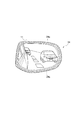
図6に示す車線変更方向検出回路15は、先行車両検出回路13で検出される先行車両の動作に基づき、先行車両の車線変更(横方向の動き)を検出する。具体的には、先行車両が自車両が走行する車線から追い越し車線へ車線変更する場合、或いは、先行車両が追い越し車線から自車両が走行する車線へ車線変更する場合、のいずれであるかを検出する。また、図7に示すように、LED11は、ドアミラー34の周囲全体に亘って複数設けられている。
The lane change
点灯制御回路16は、先行車両の挙動に応じて、LED11の点灯、消灯、及び点灯色を制御する。具体的には、先行車両との間の車間距離が短くなった場合には、前述した第1実施形態と同様に、ドアミラー34の上縁部34aに位置するLED11を点灯させる。更に、先行車両が右から左に車線変更する場合には、ドアミラー34の左下に位置するLED11を点灯させ、左から右に車線変更する場合には、ドアミラー34の右上に位置するLED11を点灯させる。詳細については、後述する。
The
次に、上述のように構成された第2実施形態に係る運転支援装置102の作用について、図8に示すフローチャートを参照して説明する。初めに、ステップS31において、先行車両検出回路13は、LRF12による検出データに基づき、自車両の走行車線の前方を走行する先行車両の有無を検出する。ステップS32において、先行車両検出回路13は、先行車両が存在するか否かを判断する。そして、先行車両が存在する場合には、ステップS33において、先行車両の変化を監視する。
Next, the operation of the driving
ステップS34において、先行車両減速検出回路14は、先行車両の変化に基づき車間距離が短くなっているか否かを判断する。即ち、自車両が先行車両に接近しつつあるか否かを判断する。例えば、先行車両がブレーキを作動させて自車両に接近している場合には、車間距離が短くなっているものと判断する。
In step S34, the preceding vehicle
そして、車間距離が短くなっていると判断された場合には(ステップS34でYES)、ステップS35において、点灯制御回路16はドアミラー34の上縁部34aに位置するLED11を点灯させる。このときの点灯色は、例えば赤色とする。その結果、自車両の乗員がドアミラー34に見入っている際に、先行車両との間の車間距離が短くなった場合に、ドアミラー34の上縁部34aに設けられた複数のLED11が点灯するので、乗員は自車両の前方に注意を向けることができる。
If it is determined that the inter-vehicle distance is short (YES in step S34), the
ステップS36において、車線変更方向検出回路15は、先行車両に変化に基づき、該先行車両が左から右に移動しているか否かを判断する。例えば、図9(a)に示すように、自車両V1の前方を走行する先行車両V4が右側の車線に車線変更しているか否かを判断する。そして、左から右に移動していると判断した場合には(ステップS36でYES)、ステップS37において、点灯制御回路16はドアミラー34の周囲に設けられる複数のLED11のうち右上に位置するLED11を点灯させる(図9(b)参照)。このときの点灯色は、例えば黄色とする。図9(b)において、黒丸で示すLEDは点灯状態を示し、白丸で示すLEDは消灯状態を示す。
In step S36, the lane change
ステップS38において、車線変更方向検出回路15は、先行車両の変化に基づき、該先行車両が右から左に移動しているか否かを判断する。例えば、図10(a)に示すように、自車両V1の隣の車線である右側前方を走行する先行車両V5が左側の車線に車線変更しているか否かを判断する。そして、右から左に移動していると判断した場合には(ステップS38でYES)、ステップS39において、点灯制御回路16はドアミラー34の周囲に設けられる複数のLED11のうち左下に位置するLED11を点灯させる(図10(b)参照)。このときの点灯色は、例えば黄色とする。
In step S38, the lane change
ステップS40において、先行車両減速検出回路14は、車間距離が長くなっているか否かを判断する。車間距離が長くなっている場合には(ステップS40でYES)、ステップS41において、点灯制御回路16はLED11を消灯する。こうして、先行車両の変化に応じてLED11を点灯させることができることになる。
In step S40, the preceding vehicle
このようにして、第2実施形態に係る運転支援装置102では、自車両と先行車両との間の車間距離が短くなった場合には、前述した第1実施形態と同様に、上縁部34aのLED11を点灯させることにより、車間距離が短くなったことを乗員に認識させる。従って、乗員の視線をいち早く自車両前方に移動させることができる。
As described above, in the driving
また、先行車両が車線変更等により左から右に移動した場合には、ドアミラー34の右上に設けられるLED11を点灯させる。即ち、ドアミラー34の左縁部及び右縁部のうち、先行車両の移動先である右縁部のLED11を、少なくとも点灯させる。従って、先行車両が右方向に移動していることを直観的に乗員に認識させることができる。
When the preceding vehicle moves from left to right due to a lane change or the like, the
更に、先行車両が右から左に移動した場合には、ドアミラー34の左下に設けられるLED11が点灯させる。即ち、ドアミラー34の左縁部及び右縁部のうち、先行車両の移動先である左縁部のLED11を、少なくとも点灯させる。従って、先行車両が左方向に移動していることを直観的に乗員に認識させることができる。
Further, when the preceding vehicle moves from the right to the left, the
また、車間距離が短くなった場合にはLED11を赤色で点灯させ、先行車両が左から右、或いは右から左に移動した場合には、LED11を黄色で点灯させるので、乗員に対してよりリスク度を認識し易い態様で表示することが可能となる。
Further, when the inter-vehicle distance becomes shorter, the
[第2実施形態の変形例の説明]
前述した第2実施形態では、ドアミラー34の周囲に配置したLED11(インジケータ)の点灯位置及び点灯色によって、先行車両との間の車間距離が短くなったこと、或いは、先行車両が横方向に移動したこと(例えば、車線変更を開始したこと)、のいずれかを区別して認識できるようにした。
[Description of Modification of Second Embodiment]
In the second embodiment described above, the distance between the vehicle and the preceding vehicle has become shorter or the preceding vehicle has moved in the lateral direction depending on the lighting position and lighting color of the LED 11 (indicator) disposed around the
これに対して、変形例では、図11に示すように、ドアミラー43の上縁部43aの上縁部43aにLED11を配置する。そして、先行車両との間の車間距離が短くなった場合には、前述した第1実施形態と同様にLED11を赤色で点灯させて乗員の注意を喚起する。一方、先行車両が車線変更等により自車両の進行方向に対して左から右に移動した場合には、図11(a)に示すように、点灯するLED11が左から右に時間差をもって点灯するように制御する。その結果、左から右へ点灯するLED11が流れるように表示される。
On the other hand, in the modified example, as shown in FIG. 11, the
更に、先行車両が自車両の進行方向に対して右から左に移動した場合には、図11(b)に示すように、右から左への移動方向に沿って、点灯するLED11が右から左に時間差をもって点灯するように制御する。その結果、右から左へ点灯するLED11が流れるように表示される。図11において、黒丸は点灯状態を示し、白丸は消灯状態を示す。このようにLED11の点灯を制御することにより、点灯するLED11が流れる向きにより、先行車両の移動方向を直感的に認識することが可能となる。
Further, when the preceding vehicle moves from right to left with respect to the traveling direction of the host vehicle, as shown in FIG. 11 (b), the
[第3実施形態の説明]
次に、本発明の第3実施形態について説明する。前述した第1,第2実施形態では、ドアミラーの周囲にLED11等のインジケータを設置し、該インジケータの点灯を制御することにより、ドアミラーに見入っている乗員の視線を自車両の前方に移動させるように誘導することについて示した。
[Description of Third Embodiment]
Next, a third embodiment of the present invention will be described. In the first and second embodiments described above, an indicator such as the
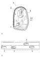
これに対して、第3実施形態では、自車両に搭載される後方撮像用のカメラを用いて、自車両後方の画像を撮像し、撮像した画像を車両のインパネ近傍に設置したモニタ(表示部)に表示する例について説明する。図12は、第3実施形態に係る運転支援装置103の構成を示すブロック図である。
On the other hand, in the third embodiment, a rear imaging camera mounted on the host vehicle is used to capture an image behind the host vehicle and the captured image is installed near the instrument panel of the vehicle (display unit) ) Will be described. FIG. 12 is a block diagram illustrating a configuration of the driving
図12に示すように、運転支援装置103は、前述した第1実施形態と同様にLRF12と、先行車両検出回路13と、先行車両減速検出回路14を備えている。更に、警報画像出力回路22と、左後方カメラ23及び右後方カメラ24と、ミラー画像生成回路25、及び画像を合成してモニタ27に表示する表示画像を生成する画像合成回路26を備えている。
As shown in FIG. 12, the driving
警報画像出力回路22は、先行車両減速検出回路14にて先行車両との間の車間距離が短くなったことが検出された場合に、モニタ27に表示する警報画像を出力する。具体的には、モニタ27に表示される後方画像の上縁部に表示する赤色の警報画像を出力する。詳細については、図14を参照して後述する。
The warning
左後方カメラ23は、自車両の左側後方を撮像して左後方画像を取得する。右後方カメラ24は、自車両の右側後方を撮像して右後方画像を取得する。
ミラー画像生成回路25は、各カメラ23、24で撮像された後方画像を鏡像変換してミラー画像を作成する。即ち、左右対称の画像とすることにより、通常のドアミラーに映し出される後方像と同一の画像を生成する。
The left
The mirror
画像合成回路26は、警報画像出力回路22より警報画像が出力された場合には、この警報画像をミラー画像生成回路25で生成された後方画像に合成して、合成画像を生成する。この合成画像をモニタ27に表示する。
When the warning image is output from the warning
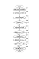
次に、上記のように構成された第3実施形態に係る運転支援装置103の処理手順を、図13に示すフローチャートを参照して説明する。初めに、ステップS51において、左後方カメラ23、及び右後方カメラ24により、自車両後方を撮像し、更に、ミラー画像生成回路25にて鏡像変換して、左後方画像、及び右後方画像を取得する。
Next, a processing procedure of the driving
ステップS52において、画像合成回路26は、左後方画像、及び右後方画像をモニタ27に表示する。その結果、例えば図14(a)に示すように、左後方画像51L及び右後方画像51Rが表示される。これにより、自車両の乗員は後方画像を車室内にて視認することができる。
In step S <b> 52, the
ステップS53において、LRF12は先行車両を検出する。ステップS54において、先行車両検出回路13は、自車両の前方を走行する先行車両が存在するか否かを検出する。先行車両が存在する場合には(ステップS54でYES)、ステップS55において、先行車両減速検出回路14は、先行車両との間の車間距離を監視し、更に、ステップS56において、車間距離が短くなっているか否かを判断する。車間距離が短くなっていると判断した場合には(ステップS56でYES)、ステップS57において、警報画像出力回路22は、モニタ27に表示するための警報画像を生成する。
In step S53, the
ステップS58において、画像合成回路26は、ミラー画像生成回路25で生成されたミラー画像に警報画像を合成し、合成画像をモニタ27に表示する。その結果、例えば、図14(b)に示すように、後方画像が表示されているモニタ27に上縁部に例えば赤色の警報画像52が表示されることになる。換言すれば、後方画像の上縁部が赤色に明灯することになる。
In step S <b> 58, the
自車両のインパネに設けられるモニタ27は、乗員の視線よりも低い位置に存在するので、モニタ27の上縁部は下縁部よりも高さ的に乗員のアイポイントに近い位置にある。従って、モニタ27の上縁部に警報画像を表示することにより、乗員の視線を自然に上方に向けさせることができ、自車両の前方に注意を向けさせることができる。
Since the
ステップS59において、先行車両減速検出回路14は、車間距離が長くなっているか否かを判断する。そして、車間距離が長くなっている場合には(ステップS59でYES)、ステップS60において、警報画像出力回路22は、警報画像の出力を終了する。従って、図14(a)に示すように、モニタ27には、通常の後方画像が表示されることになる。
In step S59, the preceding vehicle
このようにして、第3実施形態に係る運転支援装置103によれば、自車両のインパネ等にモニタ27を設置し、該モニタ27に後方画像を表示する場合において、先行車両との間の車間距離が短くなった際に、モニタ27の上縁部に警報画像52を表示する。即ち、モニタ27の上縁部を明灯させる。従って、乗員が後方映像に見入っている際に先行車両との間の車間距離が短くなった場合でも、即時にこれに乗員に気づかせて乗員の視線を自車両の前方に向けさせることができる。
Thus, according to the driving
また、モニタ27の上縁部及び下縁部のうち、高さ的に乗員のアイポイントに近い方である上縁部に警報画像52を表示するので、乗員の視線を自然な動きで前方に向けさせることができる。
In addition, since the
なお、第3実施形態に係る運転支援装置103では、先行車両との間の車間距離が短くなったときに、警報画像52を表示する例について説明したが、前述した第2実施形態と同様に、先行車両の左右方向の動きを検出し、左右方向の動きに応じて左下の領域或いは右上の領域(右後方画像の場合)、または、右下の領域或いは左上の領域(左後方画像の場合)に警報画像を表示するようにすることも可能である。この場合には、黄色の警報画像とすることが望ましい。
In the driving
[第4実施形態の説明]
次に、本発明の第4実施形態について説明する。前述した第3実施形態では、モニタ27の上縁部に警報画像52を表示する例について説明した。これに対して、第4実施形態では、モニタ27の上部を発光させ、この発光領域の面積を変化させることにより、乗員に対して注意を促す。
[Description of Fourth Embodiment]
Next, a fourth embodiment of the present invention will be described. In the third embodiment described above, the example in which the
図15は、第4実施形態に係る運転支援装置の構成を示すブロック図である。図15に示すように、第4実施形態に係る運転支援装置104は、前述した図12に示した運転支援装置103と対比して、警報表示部28を備えている点で相違する。それ以外の構成は、図12と同様であるので同一符号を付して構成説明を省略する。
FIG. 15 is a block diagram illustrating a configuration of the driving support apparatus according to the fourth embodiment. As shown in FIG. 15, the driving
警報表示部28は、図17(a)〜(c)に示すように、モニタ27の上部に設けられており、楕円形状の発光領域(符号61a、61b、61c参照)を変化させて表示する。具体的には、先行車両との間の車間距離、相対速度、或いは自車両のリスクポテンシャルに応じて発光領域を変化させる。そして、発光領域の大きさにより乗員の前方への注意を高める。リスクポテンシャルとは、自車両の走行環境において、走行環境に応じて自車両の走行を変える必要性(可能性)をリスクとして算出したものである。つまりは、例えば、先行車両との車間距離が近い場合や、自車両に対する相対速度が正で大きい場合等は、先行車に対して操舵や、制動などの操作を実行する必要性が高いとして、リスクポテンシャルを高く算出する。
As shown in FIGS. 17A to 17C, the
次に、第4実施形態に係る運転支援装置104の作用を、図16に示すフローチャートを参照して説明する。初めに、ステップS71において、左後方カメラ23、及び右後方カメラ24により、自車両後方を撮像し、更に、ミラー画像生成回路25にて鏡像変換して、左後方画像、及び右後方画像を取得する。
Next, the operation of the driving
ステップS72において、画像合成回路26は、左後方画像、及び右後方画像をモニタ27に表示する。その結果、自車両の乗員は後方画像を車室内にて視認することができる。
In step S <b> 72, the
ステップS73において、LRF12は先行車両を検出する。ステップS74において、先行車両検出回路13は、自車両の前方を走行する先行車両が存在するか否かを検出する。先行車両が存在する場合には(ステップS74でYES)、ステップS75において、先行車両減速検出回路14は、先行車両との間の車間距離を監視し、更に、ステップS76において、車間距離が短くなっているか否かを判断する。車間距離が短くなっていると判断した場合には(ステップS76でYES)、ステップS77において、警報画像出力回路22は、警報表示部28に表示する楕円形状の発光領域を発光させ、更に、距離が短くなるほど楕円を大きく表示する。
In step S73, the
その結果、図17(a)に示すように、警報表示部28にて楕円形状の領域61aが発光する。そして、車間距離が短くなるに連れて、発光する楕円が大きくなるように制御する。具体的には、図17(b)に示すように楕円形状の領域61bを発光させ、更に車間距離がより短くなった場合には、図7(c)に示すように、より大きな楕円形状の領域61cを発光させる。即ち、車間距離が短くなるほど発光領域を大きくする。
As a result, as shown in FIG. 17A, an
自車両のインパネに設けられるモニタ27は、乗員の視線よりも低い位置に存在するので、モニタ27の上部に警報表示部28を設置する方が、下部に設置するよりも高さ的に乗員のアイポイントに近い位置にある。
Since the
ステップS78において、先行車両減速検出回路14は、車間距離が長くなっているか否かを判断する。そして、車間距離が長くなっている場合には(ステップS78でYES)、ステップS79において、警報画像出力回路22は、楕円形状の発光領域を小さくする。更に、先行車両が存在しない場合には、警報表示部28に楕円を発光させない。
In step S78, the preceding vehicle
このようにして、第4実施形態に係る運転支援装置104によれば、自車両のインパネ等にモニタ27を設置し、該モニタ27に後方画像を表示する場合において、先行車両との間の車間距離が短くなった際に、モニタ27の上部の警報表示部28に、楕円状の発光領域を発光させる。従って、乗員が後方映像に見入っている際に、先行車両との間の車間距離が短くなった場合でも、即時にこれに乗員に気づかせて乗員の視線を自車両の前方に向けさせることができる。
As described above, according to the driving
また、モニタ27の上部及び下部のうち、高さ的に乗員のアイポイントに近い方である上部に警報表示部28を設けて発光領域を発光させるので、乗員の視線を自然な動きで前方に向けさせることができる。
In addition, since the
なお、第4実施形態では、車間距離の大きさに応じて楕円の大きさを変化させる例について説明したが、自車両と先行車両との間の相対速度や、自車両のリスクポテンシャルの大きさに応じて楕円の大きさを変更することも可能である。なお、リスクポテンシャルについては、周知の技術であるので詳細な説明を省略する。 In the fourth embodiment, the example in which the size of the ellipse is changed according to the size of the inter-vehicle distance has been described. However, the relative speed between the host vehicle and the preceding vehicle and the size of the risk potential of the host vehicle are described. It is also possible to change the size of the ellipse according to. The risk potential is a well-known technique and will not be described in detail.
なお、前述した第1実施形態と同様に、ウインカーの作動時を検出して、上記の処理を実行するようにしてもよい。 Note that, as in the first embodiment described above, the above-described processing may be executed by detecting the operation of the blinker.
以上、本発明の運転支援装置、及び運転支援方法を図示の実施形態に基づいて説明したが、本発明はこれに限定されるものではなく、各部の構成は、同様の機能を有する任意の構成のものに置き換えることができる。 As mentioned above, although the driving assistance apparatus and the driving assistance method of the present invention have been described based on the illustrated embodiment, the present invention is not limited to this, and the configuration of each unit is an arbitrary configuration having the same function Can be replaced.
V1 自車両
V2,V3 他車両
V4,V5 先行車両
11 LED
12 LRF
13 先行車両検出回路
14 先行車両減速検出回路
15 車線変更方向検出回路
16 点灯制御回路
21 ドアミラー
21a 上縁部
21b 下縁部
22 警報画像出力回路
23 左後方カメラ
24 右後方カメラ
25 ミラー画像生成回路
26 画像合成回路
27 モニタ
28 警報表示部
33 ルームミラー
33b 下縁部
34 ドアミラー
34a 上縁部
43 ドアミラー
43a 上縁部
51L 左後方画像
51R 右後方画像
52 警報画像
61a,61b,61c 発光領域
101,102,103,104 運転支援装置
V1 own vehicle V2, V3 other vehicle V4,
12 LRF
DESCRIPTION OF
Claims (6)
自車両の前方を走行する先行車両の挙動を検出し、
前記先行車両の挙動に応じて、前記表示部の上縁部、及び下縁部のうち、乗員のアイポイントの高さに近い方の縁部に設けた前記インジケータを明灯させること
を特徴とする運転支援方法。 A driving support method for supporting an occupant by providing an indicator on a display unit that displays a rear image,
Detecting the behavior of a preceding vehicle traveling in front of the host vehicle,
According to the behavior of the preceding vehicle, the indicator provided on the edge closer to the height of the occupant's eye point among the upper edge and the lower edge of the display section is lighted. Driving support method.
を特徴とする請求項1に記載の運転支援方法。 2. The driving support method according to claim 1, wherein a plurality of the indicators are provided at an edge portion closer to the height of the eye point of the occupant, and the indicators are turned on according to the behavior of the preceding vehicle. .
を特徴とする請求項2に記載の運転支援方法。 The said indicator is made to light up along the moving direction of a preceding vehicle, when the movement of a horizontal direction is detected as a behavior of the preceding vehicle with respect to the advancing direction of the own vehicle. Driving support method.
前記先行車両の挙動として、自車両の進行方向に対し横方向の移動が検出された場合には、前記左縁部及び右縁部のインジケータのうち先行車両の移動先のインジケータを明灯させること
を特徴とする請求項2に記載の運転支援方法。 In addition to the edge of the display unit close to the height of the occupant's eye point, a plurality of indicators are provided on the left edge and the right edge,
As a behavior of the preceding vehicle, when a movement in a lateral direction with respect to the traveling direction of the host vehicle is detected, the indicator of the destination of the preceding vehicle among the indicators of the left edge portion and the right edge portion is lit. The driving support method according to claim 2, wherein
を特徴とする請求項1に記載の運転支援方法。 2. The light emitting area of the warning display section is changed based on the behavior of the preceding vehicle, and a warning display section that changes a light emitting area is provided at an upper edge of the display section. Driving support method.
自車両の前方を走行する先行車両の挙動を検出する先行車両検出回路と、
前記先行車両の挙動に応じて、前記表示部の上縁部、及び下縁部のうち、乗員のアイポイントの高さに近い方の縁部に設けたインジケータを明灯させる明灯制御回路と
を備えたことを特徴とする運転支援装置。 A driving support device that provides an indicator on a display unit that displays a rear image, lights the indicator according to the surrounding situation of the host vehicle, and assists an occupant,
A preceding vehicle detection circuit for detecting the behavior of a preceding vehicle traveling in front of the host vehicle;
A lighting control circuit for lighting an indicator provided on an edge closer to the height of the occupant's eye point, of the upper edge and the lower edge of the display unit according to the behavior of the preceding vehicle. A driving support device characterized by that.
Priority Applications (1)
| Application Number | Priority Date | Filing Date | Title |
|---|---|---|---|
| JP2016071248A JP2017178172A (en) | 2016-03-31 | 2016-03-31 | Drive support method and drive support apparatus |
Applications Claiming Priority (1)
| Application Number | Priority Date | Filing Date | Title |
|---|---|---|---|
| JP2016071248A JP2017178172A (en) | 2016-03-31 | 2016-03-31 | Drive support method and drive support apparatus |
Publications (1)
| Publication Number | Publication Date |
|---|---|
| JP2017178172A true JP2017178172A (en) | 2017-10-05 |
Family
ID=60004841
Family Applications (1)
| Application Number | Title | Priority Date | Filing Date |
|---|---|---|---|
| JP2016071248A Pending JP2017178172A (en) | 2016-03-31 | 2016-03-31 | Drive support method and drive support apparatus |
Country Status (1)
| Country | Link |
|---|---|
| JP (1) | JP2017178172A (en) |
Cited By (3)
| Publication number | Priority date | Publication date | Assignee | Title |
|---|---|---|---|---|
| JP2020052559A (en) * | 2018-09-25 | 2020-04-02 | 本田技研工業株式会社 | Vehicle control device, vehicle control method, and program |
| JPWO2019220229A1 (en) * | 2018-05-15 | 2021-02-18 | ロベルト・ボッシュ・ゲゼルシャフト・ミト・ベシュレンクテル・ハフツングRobert Bosch Gmbh | ECU and lane departure warning system |
| JP2021039554A (en) * | 2019-09-03 | 2021-03-11 | 株式会社デンソー | Gazing guidance device for vehicle |
Citations (6)
| Publication number | Priority date | Publication date | Assignee | Title |
|---|---|---|---|---|
| JP2005346372A (en) * | 2004-06-02 | 2005-12-15 | Nissan Motor Co Ltd | Driving operation auxiliary device for vehicle and vehicle having it |
| JP2010097270A (en) * | 2008-10-14 | 2010-04-30 | Toyota Motor Corp | Information provision device |
| JP2011086205A (en) * | 2009-10-16 | 2011-04-28 | Honda Motor Co Ltd | Traveling safety device for vehicle |
| CN102233854A (en) * | 2010-04-21 | 2011-11-09 | Smr专利责任有限公司 | Side rear view mirror assembly indicator of blind spot occupancy |
| DE102011106838A1 (en) * | 2011-07-07 | 2013-01-10 | Volkswagen Aktiengesellschaft | Outside rear view mirror for motor vehicle, has light display device, which is provided with two or more separately controllable light segments, where light display device consisting of light segments is formed with light strip |
| JP2015209061A (en) * | 2014-04-25 | 2015-11-24 | スタンレー電気株式会社 | Vehicle side mirror alarm device |
-
2016
- 2016-03-31 JP JP2016071248A patent/JP2017178172A/en active Pending
Patent Citations (6)
| Publication number | Priority date | Publication date | Assignee | Title |
|---|---|---|---|---|
| JP2005346372A (en) * | 2004-06-02 | 2005-12-15 | Nissan Motor Co Ltd | Driving operation auxiliary device for vehicle and vehicle having it |
| JP2010097270A (en) * | 2008-10-14 | 2010-04-30 | Toyota Motor Corp | Information provision device |
| JP2011086205A (en) * | 2009-10-16 | 2011-04-28 | Honda Motor Co Ltd | Traveling safety device for vehicle |
| CN102233854A (en) * | 2010-04-21 | 2011-11-09 | Smr专利责任有限公司 | Side rear view mirror assembly indicator of blind spot occupancy |
| DE102011106838A1 (en) * | 2011-07-07 | 2013-01-10 | Volkswagen Aktiengesellschaft | Outside rear view mirror for motor vehicle, has light display device, which is provided with two or more separately controllable light segments, where light display device consisting of light segments is formed with light strip |
| JP2015209061A (en) * | 2014-04-25 | 2015-11-24 | スタンレー電気株式会社 | Vehicle side mirror alarm device |
Cited By (5)
| Publication number | Priority date | Publication date | Assignee | Title |
|---|---|---|---|---|
| JPWO2019220229A1 (en) * | 2018-05-15 | 2021-02-18 | ロベルト・ボッシュ・ゲゼルシャフト・ミト・ベシュレンクテル・ハフツングRobert Bosch Gmbh | ECU and lane departure warning system |
| JP2020052559A (en) * | 2018-09-25 | 2020-04-02 | 本田技研工業株式会社 | Vehicle control device, vehicle control method, and program |
| CN110949389A (en) * | 2018-09-25 | 2020-04-03 | 本田技研工业株式会社 | Vehicle control device, vehicle control method, and storage medium |
| JP2021039554A (en) * | 2019-09-03 | 2021-03-11 | 株式会社デンソー | Gazing guidance device for vehicle |
| JP7287199B2 (en) | 2019-09-03 | 2023-06-06 | 株式会社デンソー | Vehicle gaze guidance device |
Similar Documents
| Publication | Publication Date | Title |
|---|---|---|
| JP7302063B2 (en) | Image projection device and image projection method | |
| JP6814153B2 (en) | Vehicle lighting, vehicle systems and vehicles | |
| CN106794792B (en) | Road surface drawing system for vehicle | |
| US10943487B2 (en) | Control apparatus, control system, and control program for vehicle | |
| JPWO2015037117A1 (en) | Information display system and information display device | |
| EP1878616B1 (en) | Vehicle light warning system and method | |
| CN109204305B (en) | Method for enriching the field of view, device for use in an observer vehicle and object, and motor vehicle | |
| KR20180132668A (en) | Method for controlling automatic display of a pictogram indicating the presence of a distress situation in front of a vehicle | |
| JP2009067083A (en) | Headlight device for vehicle and its control method | |
| US10220771B2 (en) | Method and driver assistance system for assisting a driver of a vehicle | |
| WO2015178303A1 (en) | Safety confirmation assist device | |
| JP2016199072A (en) | Vehicular display system | |
| JP2017178172A (en) | Drive support method and drive support apparatus | |
| JP4731177B2 (en) | Infrared imaging display device and infrared imaging display method for vehicle | |
| JP4665841B2 (en) | Warning device for vehicle | |
| JP2010247621A (en) | Drive support system of automobile | |
| JP2014106635A (en) | Lighting fixture system for vehicle | |
| KR20110057837A (en) | Night view system and control method thereof | |
| JP2015232846A (en) | Front situation determination device | |
| JP7287199B2 (en) | Vehicle gaze guidance device | |
| JP2018118537A (en) | Visually recognizing device for vehicle | |
| JP6596055B2 (en) | Emergency vehicle notification device | |
| JP2012030752A (en) | Vehicular display device | |
| JP2008195330A (en) | Side mirror and warning device | |
| JPWO2020100655A1 (en) | Vehicle lighting system |
Legal Events
| Date | Code | Title | Description |
|---|---|---|---|
| A621 | Written request for application examination |
Free format text: JAPANESE INTERMEDIATE CODE: A621 Effective date: 20190122 |
|
| A131 | Notification of reasons for refusal |
Free format text: JAPANESE INTERMEDIATE CODE: A131 Effective date: 20191119 |
|
| A977 | Report on retrieval |
Free format text: JAPANESE INTERMEDIATE CODE: A971007 Effective date: 20191121 |
|
| A521 | Request for written amendment filed |
Free format text: JAPANESE INTERMEDIATE CODE: A523 Effective date: 20200108 |
|
| A02 | Decision of refusal |
Free format text: JAPANESE INTERMEDIATE CODE: A02 Effective date: 20200512 |