JP2017176068A - Riding lawn mower vehicle - Google Patents

Riding lawn mower vehicle Download PDF

Info

Publication number
JP2017176068A
JP2017176068A JP2016070103A JP2016070103A JP2017176068A JP 2017176068 A JP2017176068 A JP 2017176068A JP 2016070103 A JP2016070103 A JP 2016070103A JP 2016070103 A JP2016070103 A JP 2016070103A JP 2017176068 A JP2017176068 A JP 2017176068A
Authority
JP
Japan
Prior art keywords
vehicle
wheel
lawn mower
riding
sensors
Prior art date
Legal status (The legal status is an assumption and is not a legal conclusion. Google has not performed a legal analysis and makes no representation as to the accuracy of the status listed.)
Pending
Application number
JP2016070103A
Other languages
Japanese (ja)
Inventor
河合 良一
Ryoichi Kawai
良一 河合
浩彦 川田
Hirohiko Kawada
浩彦 川田
小瀬川 征志
Seishi Ozekawa
征志 小瀬川
Current Assignee (The listed assignees may be inaccurate. Google has not performed a legal analysis and makes no representation or warranty as to the accuracy of the list.)
Kanzaki Kokyukoki Manufacturing Co Ltd
Original Assignee
Kanzaki Kokyukoki Manufacturing Co Ltd
Priority date (The priority date is an assumption and is not a legal conclusion. Google has not performed a legal analysis and makes no representation as to the accuracy of the date listed.)
Filing date
Publication date
Application filed by Kanzaki Kokyukoki Manufacturing Co Ltd filed Critical Kanzaki Kokyukoki Manufacturing Co Ltd
Priority to JP2016070103A priority Critical patent/JP2017176068A/en
Priority to US15/473,024 priority patent/US10638661B2/en
Publication of JP2017176068A publication Critical patent/JP2017176068A/en
Priority to US16/826,663 priority patent/US20200288631A1/en
Pending legal-status Critical Current

Links

Images

Abstract

PROBLEM TO BE SOLVED: To realize a configuration which facilitates automatic detection of an obstacle approaching a vehicle at the time of turning backward in a riding lawn mower vehicle with a configuration in which left and right wheels are independently driven to travel by a motor.SOLUTION: A riding lawn mower vehicle 10 includes: a driving source; a left wheel 12 and a right wheel 13; a transmission configured to independently drive the left wheel 12 and the right wheel 13 in response to power from the driving source in terms of a rotation direction and a rotation speed; caster wheels 15, 16 provided apart from the left wheel 12 and the right wheel 13 in a front-rear direction; a lawn mower 18; and two first sensors 50a, 50b disposed on both left and right sides in front of a rear end of the vehicle and configured to detect an obstacle located on the rear side.SELECTED DRAWING: Figure 2

Description

本発明は、駆動源と、回転方向及び回転速度についてそれぞれ独立して駆動可能である左車輪及び右車輪と、左車輪及び右車輪に対し前後方向に離れて設けられたキャスタ輪と、芝刈り機とを備える乗用型芝刈車両に関する。   The present invention includes a drive source, a left wheel and a right wheel that can be driven independently with respect to the rotation direction and the rotation speed, a caster wheel that is provided away from the left wheel and the right wheel in the front-rear direction, and mowing the lawn. The present invention relates to a riding lawnmower equipped with a machine.

芝刈り作業を行うために駆動される芝刈機を備える芝刈車両が、従来から知られている。また、このような芝刈車両において、それぞれ電動モータや油圧モータ等のモータにより独立に走行駆動される主駆動輪である左車輪及び右車輪と、キャスタ輪とを備える芝刈車両も考えられている。   2. Description of the Related Art Lawn mower vehicles including lawn mowers that are driven to perform lawn mowing work are conventionally known. Further, in such a lawnmower vehicle, a lawnmower vehicle including left and right wheels, which are main drive wheels that are independently driven by a motor such as an electric motor or a hydraulic motor, and caster wheels has been considered.

また、芝刈車両として、作業者が乗り込んで走行と芝刈の操縦を車上で行う自力走行が可能な芝刈車両があり、これは乗用型芝刈車両と呼ばれる。芝刈機としては、例えば、プロペラ式回転刃タイプや回転巻刃タイプの芝刈回転工具等がある。   In addition, there is a lawnmower vehicle capable of self-running where an operator gets on and runs and controls the lawn mower on the vehicle, which is called a riding lawnmower vehicle. Examples of the lawn mower include a propeller type rotary blade type and a rotary winding blade type lawn mower rotary tool.

乗用型芝刈車両は、もっぱら庭等のいわゆるオフロードで用いられ、芝刈作業のために地表を移動するものである。   Riding lawn mowers are used exclusively in so-called off-roads such as gardens, and move on the ground for mowing work.

例えば、特許文献1には、内燃機関のエンジンシャフトにロータを連結したエンジン・発電機一体型を搭載するハイブリッド動力装置が記載されている。動力装置として例示されている芝刈車両は、複数の駆動輪にそれぞれ独立の電気モータが連結され、それぞれの駆動輪を独立的に可変速度で制御でき、これによって芝刈車両のスムーズな始動、停止、速度変更、方向転換を行うことができると述べられている。特許文献1の図4及びその説明には、ゼロ回転半径で旋回可能な芝刈車両が記載されている。   For example, Patent Document 1 describes a hybrid power unit equipped with an engine / generator integrated type in which a rotor is connected to an engine shaft of an internal combustion engine. A lawnmower vehicle exemplified as a power unit has a plurality of drive wheels connected to independent electric motors, and each drive wheel can be controlled independently at a variable speed, whereby the lawn mower vehicle can be started and stopped smoothly. It is stated that speed change and direction change can be performed. FIG. 4 of Patent Document 1 and the description thereof describe a lawnmower vehicle that can turn with a zero turning radius.

特表2006−507789号公報JP 2006-507789 A

特許文献1の図4及びその説明に記載された車両の場合、左右の後輪の速度を異ならせることで旋回が可能である。このような車両では小さい回転半径で急旋回を行える。この場合、運転者は後を振り返りながら後方への旋回を行う。しかしながら、運転者の視野に対して死角になる領域に障害対象がある場合、それを確認できないおそれがある。特に、車両の運転席より後側で車両の後端よりも前側において、左右方向の外側に人または物である障害対象があるときに、それを確認することができない可能性がある。これにより、後方への旋回走行時に、障害対象を自動で検知しやすい構成の実現が望まれる。   In the case of the vehicle described in FIG. 4 of Patent Document 1 and its description, the vehicle can turn by changing the speeds of the left and right rear wheels. Such a vehicle can make a sharp turn with a small turning radius. In this case, the driver turns backward while looking back. However, if there is a failure target in a blind area with respect to the driver's field of view, there is a possibility that it cannot be confirmed. In particular, when there is an obstacle object that is a person or an object in the lateral direction outside the driver's seat and in front of the rear end of the vehicle, it may not be confirmed. Accordingly, it is desired to realize a configuration that can easily detect an obstacle target when turning backward.

後方への旋回走行時に障害対象を自動で検知できれば、例えば障害対象に衝突することを回避しやすい。また、芝刈車両では、後方への旋回走行時に芝刈機に障害対象が近づくことにより、障害対象が芝刈機に巻き込まれるおそれがある。後方への旋回走行時に障害対象を自動で検知できれば、後方への旋回走行時に芝刈機に対し障害対象が巻き込まれることを回避しやすい。   If the obstacle target can be automatically detected when turning backward, for example, it is easy to avoid collision with the obstacle target. In the lawn mower vehicle, the obstacle target may be caught in the lawn mower when the obstacle target approaches the lawn mower when turning backward. If the obstacle target can be automatically detected when turning backward, it is easy to avoid the obstacle target being caught in the lawn mower when turning backward.

本発明の目的は、乗用型芝刈車両において、左右車輪が、回転方向及び回転速度についてそれぞれ独立して駆動可能である構成において、後方への旋回走行時に車両に接近する障害対象を自動で検知しやすい構成を実現することである。   An object of the present invention is to automatically detect an obstacle object approaching the vehicle when turning backwards in a riding-type lawn mower vehicle in which the left and right wheels can be independently driven in the rotational direction and the rotational speed. It is to realize an easy configuration.

本発明に係る乗用型芝刈車両は、駆動源と、左車輪及び右車輪と、前記駆動源からの動力を受けて前記左車輪及び前記右車輪を、回転方向及び回転速度についてそれぞれ独立して駆動可能に構成したトランスミッションと、前記左車輪及び前記右車輪に対し前後方向に離れて設けられたキャスタ輪と、芝刈機と、を備える乗用型芝刈車両であって、車両の後端よりも前側において左右両側に配置される2つの第1センサであって、後側に位置する障害対象を検知するように構成される2つの第1センサを備える。   The riding lawn mower according to the present invention drives the left wheel and the right wheel independently of each other with respect to the rotation direction and the rotation speed by receiving power from the drive source, the left wheel and the right wheel, and the drive source. A riding lawnmower vehicle comprising a transmission configured to be possible, a caster wheel provided away from the left wheel and the right wheel in the front-rear direction, and a lawn mower, on the front side of the rear end of the vehicle Two first sensors arranged on both the left and right sides, and provided with two first sensors configured to detect a failure target located on the rear side.

本発明に係る乗用型芝刈車両によれば、左右車輪が、回転方向及び回転速度についてそれぞれ独立して駆動可能である構成において、後方への旋回走行時に車両に接近する障害対象を自動で検知しやすい。特に、2つの第1センサのそれぞれは、車両の後端よりも前側において、左右両側に配置され、後側に位置する障害対象を検知するように構成されるので、車両の後端に後方を検知可能なセンサが配置される場合と異なり、車両の左右両端より外側で車両の後端より前側に位置する障害対象も検知しやすい。   According to the riding lawn mower vehicle according to the present invention, in the configuration in which the left and right wheels can be driven independently with respect to the rotation direction and the rotation speed, the obstacle object approaching the vehicle is automatically detected when turning backward. Cheap. In particular, each of the two first sensors is disposed on both the left and right sides in front of the rear end of the vehicle, and is configured to detect a failure target located on the rear side. Unlike the case where sensors that can be detected are arranged, it is easy to detect a fault target located outside the left and right ends of the vehicle and ahead of the rear end of the vehicle.

本発明に係る実施形態の乗用型芝刈車両の斜視図である。1 is a perspective view of a riding lawn mower vehicle according to an embodiment of the present invention. 実施形態の車両を上方から見て第1センサの検知範囲を示す図である。It is a figure which shows the detection range of a 1st sensor seeing the vehicle of embodiment from upper direction. 実施形態の車両の特徴構成を示すブロック図である。It is a block diagram which shows the characteristic structure of the vehicle of embodiment. 実施形態の車両において、左車輪用及び右車輪用の動力発生ユニットとエンジンとの動力伝達構造を上側から見た図である。It is the figure which looked at the power transmission structure of the power generation unit for left wheels and right wheels, and an engine from the upper side in the vehicle of embodiment. 実施形態の車両において、左車輪用及び右車輪用の動力発生ユニットの油圧回路を示す図である。In the vehicle of an embodiment, it is a figure showing a hydraulic circuit of a power generation unit for left wheels and right wheels. 実施形態の車両において、直進走行の状態を示す略図である。In the vehicle of an embodiment, it is a schematic diagram showing the state of straight running. 実施形態の車両において、前側への旋回走行の状態を示す略図である。In the vehicle of an embodiment, it is a schematic diagram showing the state of the turning run to the front side. 実施形態の車両において、左右車輪の一方車輪を中心として旋回する状態を示す略図である。In the vehicle of an embodiment, it is a schematic diagram showing the state where it turns centering on one wheel of a right-and-left wheel. 実施形態の車両において、左右車輪の間の中央を中心として旋回する状態を示す略図である。In the vehicle of an embodiment, it is a schematic diagram showing the state where it turns around the center between right-and-left wheels. 実施形態の車両において、後方に旋回したときの不都合を示す略図である。In the vehicle of an embodiment, it is a schematic diagram showing inconvenience when turning backward. 図2の状態から車両がα方向に超信地旋回してセンサが障害物を検知したときの状態を示している図である。FIG. 3 is a diagram showing a state when the vehicle turns in the α direction from the state of FIG. 2 and a sensor detects an obstacle. 図2の状態から車両がβ方向に超信地旋回してセンサが障害物を検知したときの状態を示している図である。FIG. 3 is a diagram showing a state when the vehicle turns in the β direction from the state of FIG. 2 and a sensor detects an obstacle. 本発明に係る実施形態の別例の乗用型芝刈車両の特徴構成を示すブロック図である。It is a block diagram which shows the characteristic structure of the riding type lawn mower vehicle of another example of embodiment which concerns on this invention. 図10に示す構成において、図2に対応する図である。In the structure shown in FIG. 10, it is a figure corresponding to FIG. 本発明に係る実施形態の別例の乗用型芝刈車両の特徴構成を示すブロック図である。It is a block diagram which shows the characteristic structure of the riding type lawn mower vehicle of another example of embodiment which concerns on this invention.

以下に図面を用いて本発明に係る実施形態につき詳細に説明する。なお、以下では、主として、乗用型芝刈車両の左右車輪が走行用モータとして油圧モータで駆動される構成を説明するが、走行用モータは電動モータ等、他のモータとしてもよい。以下では左右の主駆動輪としての車輪が後側に配置され、キャスタ輪が前側に配置された場合を説明するが、車輪が前側でキャスタ輪が後側でもよい。   Hereinafter, embodiments of the present invention will be described in detail with reference to the drawings. In the following description, a configuration in which the left and right wheels of the riding lawn mower vehicle are driven by a hydraulic motor as a traveling motor will be mainly described. However, the traveling motor may be another motor such as an electric motor. In the following, the case where the wheels as the left and right main drive wheels are arranged on the rear side and the caster wheels are arranged on the front side will be described, but the wheels may be on the front side and the caster wheels may be on the rear side.

以下で述べる形状、個数、部品の配置関係等は、説明のための例示であって、乗用型芝刈車両の仕様等に合わせ、適宜変更が可能である。また、以下では、全ての図面において同様の要素には同一の符号を付し、重複する説明を省略もしくは簡略化する。   The shape, the number, the arrangement relationship of components, and the like described below are examples for explanation, and can be appropriately changed according to the specification of the riding lawnmower. Also, in the following, the same reference numerals are given to the same elements in all the drawings, and overlapping descriptions are omitted or simplified.

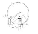
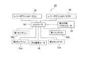
図1から図9は、実施形態に係る乗用型芝刈車両を示している。以下では、乗用型芝刈車両10は、車両10と記載する。図1は、車両10の斜視図である。図2は、車両10を上方から見て第1センサ50a、50bの検知範囲を示す図である。図3は、車両10の特徴構成を示すブロック図である。図4Aは、車両10において、左車輪12用及び右車輪13用の動力発生ユニット26,27とエンジン14との動力伝達構造を上側から見た図である。図4Bは、車両10において、左車輪12用及び右車輪13用の動力発生ユニット26,27の油圧回路28,29を示す図である。   1 to 9 show a riding lawnmower according to an embodiment. Hereinafter, the riding lawnmower vehicle 10 is referred to as a vehicle 10. FIG. 1 is a perspective view of the vehicle 10. FIG. 2 is a diagram illustrating detection ranges of the first sensors 50a and 50b when the vehicle 10 is viewed from above. FIG. 3 is a block diagram showing a characteristic configuration of the vehicle 10. 4A is a view of the power transmission structure between the power generation units 26 and 27 for the left wheel 12 and the right wheel 13 and the engine 14 in the vehicle 10 as viewed from above. FIG. 4B is a diagram illustrating hydraulic circuits 28 and 29 of power generation units 26 and 27 for the left wheel 12 and the right wheel 13 in the vehicle 10.

車両10は、芝刈に適した自走型のオフロード用車両である。車両10は、左車輪12及び右車輪13と、キャスタ輪15,16と、芝刈機18と、2つの第1センサ50a、50bと、張力切換アクチュエータ43(図3、図4A)と、制御装置であるコントローラ60(図3)とを備える。   The vehicle 10 is a self-propelled off-road vehicle suitable for lawn mowing. The vehicle 10 includes a left wheel 12 and a right wheel 13, caster wheels 15 and 16, a lawn mower 18, two first sensors 50a and 50b, a tension switching actuator 43 (FIGS. 3 and 4A), and a control device. And a controller 60 (FIG. 3).

左車輪12及び右車輪13は、車体であるメインフレーム20の後側の左右両側に支持される後輪であり、かつ主駆動輪である。メインフレーム20は、鋼材等の金属により、梁構造等に形成される。メインフレーム20は、左右両端で略前後方向に伸びる側板部20a、20bと、左右両側の側板部20a、20bを連結する連結部20cとを含む。左右の側板部20a、20bの後端部の間で、上側には運転車が座る運転席21が固定される。   The left wheel 12 and the right wheel 13 are rear wheels supported on the left and right sides on the rear side of the main frame 20 that is a vehicle body, and are main drive wheels. The main frame 20 is formed in a beam structure or the like from a metal such as a steel material. The main frame 20 includes side plate portions 20a and 20b extending substantially in the front-rear direction at both left and right ends, and a connecting portion 20c that connects the left and right side plate portions 20a and 20b. Between the rear end portions of the left and right side plate portions 20a and 20b, a driver seat 21 on which a driver vehicle sits is fixed on the upper side.

メインフレーム20において、運転席21の前側フロアから突き出るように左右の操縦レバー22,23が支持されている。各操縦レバー22,23の先端部は、運転者が掴んで左車輪12及び右車輪13の回転方向及び回転速度を指示するために用いられる。各操縦レバー22,23は、略L字形であり、上端部に左右方向に伸びる把持部24が形成される。把持部24は、運転者に掴まれて操作される。各操縦レバー22,23は、下端部において、左右方向に沿う軸を中心として揺動可能である。   In the main frame 20, left and right control levers 22 and 23 are supported so as to protrude from the front floor of the driver's seat 21. The tips of the control levers 22 and 23 are used by the driver to indicate the rotation direction and rotation speed of the left wheel 12 and the right wheel 13. Each control lever 22 and 23 is substantially L-shaped, and a grip portion 24 extending in the left-right direction is formed at the upper end portion. The grip portion 24 is operated by being gripped by the driver. Each of the control levers 22 and 23 can swing around an axis along the left-right direction at the lower end.

左車輪12及び右車輪13は、メインフレーム20の側板部20a、20bの左右方向外端より外側にはみ出している。各車輪12,13の上側は、車輪カバー25で少なくとも一部が覆われており、車輪カバー25の左右方向内側端部は側板部20a、20bに固定されている。   The left wheel 12 and the right wheel 13 protrude outside the left and right outer ends of the side plate portions 20a and 20b of the main frame 20. The upper side of each wheel 12, 13 is at least partially covered with a wheel cover 25, and the inner end in the left-right direction of the wheel cover 25 is fixed to the side plate portions 20 a, 20 b.

左右の2つのキャスタ輪15,16は、メインフレーム20の前端部に支持される操向輪であり、かつ前輪である。左車輪12及び右車輪13は、2個の走行用モータである後述の左油圧モータ30(図4B)及び右油圧モータ31(図4B)により、それぞれ独立に走行駆動される。これにより、各キャスタ輪15,16は、車両10の前後方向において、左車輪12及び右車輪13に対し前後方向に離れて設けられる。各キャスタ輪15,16は、鉛直方向(図1の上下方向)の軸を中心として360度以上の自由回転が可能である。なお、キャスタ輪は、車両に2つ配置される構成に限定するものではなく、1つのみ、または3つ以上が車両に配置されてもよい。以下では、左車輪12及び右車輪13は、左右車輪12,13と記載する場合がある。   The two left and right caster wheels 15 and 16 are steered wheels supported by the front end portion of the main frame 20 and are front wheels. The left wheel 12 and the right wheel 13 are independently driven by a left hydraulic motor 30 (FIG. 4B) and a right hydraulic motor 31 (FIG. 4B), which will be described later, which are two traveling motors. Accordingly, the caster wheels 15 and 16 are provided away from the left wheel 12 and the right wheel 13 in the front-rear direction in the front-rear direction of the vehicle 10. Each of the caster wheels 15 and 16 can freely rotate 360 degrees or more around the axis in the vertical direction (the vertical direction in FIG. 1). Note that the number of caster wheels is not limited to a configuration in which two caster wheels are arranged in the vehicle, and only one or three or more caster wheels may be arranged in the vehicle. Below, the left wheel 12 and the right wheel 13 may be described as the left and right wheels 12 and 13.

図4Bに示すように、左車輪12及び右車輪13は、トランスミッション11によって回転方向及び回転速度について、それぞれ独立して駆動可能である。トランスミッション11は、左右の動力発生ユニット26,27を含む。トランスミッション11には、駆動源としてのエンジン14の動力が入力され、左右車輪12,13の駆動軸に、左右の油圧ポンプ32,33の出力が減速歯車機構26b、27bを介して出力される。これにより、トランスミッション11は、エンジン14からの動力を受けて、左車輪12及び右車輪13を、回転方向及び回転速度についてそれぞれ独立して駆動可能に構成する。左右の、固定容積型の油圧モータ30,31は、それぞれ左右の動力発生ユニット26,27を構成する。左右の油圧モータ30,31は、左車輪12及び右車輪13の駆動軸に、それぞれ連結される。各動力発生ユニット26,27は、車輪用の動力を発生させるもので、ケース26a、27aと、その内側の油圧回路28,29とを含む。各油圧回路28,29は、斜板式可変容量型の油圧ポンプ32,33と、油圧ポンプ32,33から圧油が供給されて駆動される油圧モータ30,31と、油圧ポンプ32,33及び油圧モータ30,31を接続する油路34とを有する。油圧モータ30,31は、例えば固定容量型である。油圧ポンプ32,33の駆動軸32a,33aには従動プーリ35がそれぞれ固定されており、後述の動力源としてのエンジン14によりベルト36を介して駆動される。前記油圧ポンプ32,33は前記トランスミッション11の入力部として機能する。   As shown in FIG. 4B, the left wheel 12 and the right wheel 13 can be independently driven by the transmission 11 with respect to the rotation direction and the rotation speed. The transmission 11 includes left and right power generation units 26 and 27. The power of the engine 14 as a drive source is input to the transmission 11, and the outputs of the left and right hydraulic pumps 32 and 33 are output to the drive shafts of the left and right wheels 12 and 13 via the reduction gear mechanisms 26b and 27b. Thereby, the transmission 11 receives the motive power from the engine 14, and comprises the left wheel 12 and the right wheel 13 so that it can drive independently about a rotation direction and a rotational speed, respectively. The left and right, fixed displacement hydraulic motors 30 and 31 constitute left and right power generation units 26 and 27, respectively. The left and right hydraulic motors 30 and 31 are connected to the drive shafts of the left wheel 12 and the right wheel 13, respectively. Each power generation unit 26, 27 generates power for wheels, and includes cases 26a, 27a and hydraulic circuits 28, 29 inside thereof. The hydraulic circuits 28 and 29 include swash plate type variable displacement hydraulic pumps 32 and 33, hydraulic motors 30 and 31 driven by pressure oil supplied from the hydraulic pumps 32 and 33, hydraulic pumps 32 and 33, and hydraulic pressure. And an oil passage 34 connecting the motors 30 and 31. The hydraulic motors 30 and 31 are, for example, fixed capacity types. The driven pulleys 35 are fixed to the drive shafts 32a and 33a of the hydraulic pumps 32 and 33, respectively, and are driven via a belt 36 by an engine 14 as a power source described later. The hydraulic pumps 32 and 33 function as an input unit of the transmission 11.

油圧ポンプ32,33は、回転によって可動斜板の傾転角度及び向きを変化させる左調節軸である左斜板操作軸32b及び右調節軸である右斜板操作軸33bと、斜板操作軸32b、33bに連結された斜板操作レバー32c、33cとを含む。左斜板操作軸32bは、左油圧ポンプ32の圧油吐出量を調節する。右斜板操作軸33bは、右油圧ポンプ33の圧油吐出量を調節する。斜板操作レバー32c、33cには、左右の対応する側の操縦レバー22,23の下端部が、それぞれリンク37を介して連結される。これにより、操縦レバー22,23が前後方向に揺動することで、斜板操作軸32b、33bが回転する。そして、油圧ポンプ32,33の可動斜板の傾転角度及び向きが変化する。可動斜板の傾転角度の変更によって、油圧ポンプ32,33の吐出量が変化する。操縦レバー22,23が大きく前または後に倒れることで、油圧ポンプ32,33の吐出量が大きくなる。左油圧モータ30は左油圧ポンプ32からの圧油供給で駆動される。右油圧モータ31は右油圧ポンプ33からの圧油供給で駆動される。操縦レバー22,23が中立状態より前側に倒れることで油圧ポンプ32,33は油圧モータ30,31を一方側に回転させるように吐出方向が規定される。操縦レバー22,23が中立状態より後側に倒れることで油圧ポンプ32,33は油圧モータ30,31を他方側に回転させるように吐出方向が規定される。中立状態は、操縦レバー22,23が運転者に掴まれない状態で自動的に復帰する位置にあり油の吐出が無い状態である。油圧モータ30,31の回転方向について、一方側は車輪12,13の前進方向の回転に対応し、他方側は車輪12,13の後進方向の回転に対応する。また、操縦レバー22,23の揺動角度位置は、揺動角度検出部であるレバーポテンショメータ38,39により検出される。レバーポテンショメータ38,39の検出信号は後述のコントローラ60(図3)に送信される。   The hydraulic pumps 32 and 33 include a left swash plate operation shaft 32b that is a left adjustment shaft that changes the tilt angle and direction of the movable swash plate by rotation, a right swash plate operation shaft 33b that is a right adjustment shaft, and a swash plate operation shaft. And swash plate operating levers 32c and 33c connected to 32b and 33b. The left swash plate operating shaft 32 b adjusts the pressure oil discharge amount of the left hydraulic pump 32. The right swash plate operating shaft 33 b adjusts the pressure oil discharge amount of the right hydraulic pump 33. The swash plate operation levers 32c and 33c are connected to the lower end portions of the left and right control levers 22 and 23 via links 37, respectively. As a result, the control levers 22 and 23 swing in the front-rear direction, whereby the swash plate operating shafts 32b and 33b rotate. Then, the tilt angle and direction of the movable swash plate of the hydraulic pumps 32 and 33 change. The discharge amount of the hydraulic pumps 32 and 33 is changed by changing the tilt angle of the movable swash plate. When the control levers 22 and 23 are largely tilted forward or backward, the discharge amounts of the hydraulic pumps 32 and 33 are increased. The left hydraulic motor 30 is driven by pressure oil supplied from the left hydraulic pump 32. The right hydraulic motor 31 is driven by pressure oil supplied from the right hydraulic pump 33. When the control levers 22 and 23 are tilted forward from the neutral state, the discharge directions of the hydraulic pumps 32 and 33 are regulated so as to rotate the hydraulic motors 30 and 31 to one side. When the control levers 22 and 23 are tilted backward from the neutral state, the discharge directions of the hydraulic pumps 32 and 33 are regulated so as to rotate the hydraulic motors 30 and 31 to the other side. The neutral state is a state in which the control levers 22 and 23 are automatically returned in a state where the control levers 22 and 23 are not grasped by the driver and no oil is discharged. Regarding the rotation direction of the hydraulic motors 30, 31, one side corresponds to rotation in the forward direction of the wheels 12, 13, and the other side corresponds to rotation in the reverse direction of the wheels 12, 13. Further, the swing angle positions of the control levers 22 and 23 are detected by lever potentiometers 38 and 39 which are swing angle detection units. Detection signals from the lever potentiometers 38 and 39 are transmitted to a controller 60 (FIG. 3) described later.

また、図4Bの油圧回路28,29では、油圧ポンプ32,33及び油圧モータ30,31を接続する2つの主油路S1,S2にチャージ油路C1が接続される。チャージ油路C1は、各主油路S1,S2と油溜まりEとをチェック弁F1、F2を介して接続する。チャージ油路C1は、主油路S1,S2のうち、低圧側の主油路に油溜まりEから油が補充される。また、主油路S1,S2の両方と油溜まりEとの間にはバイパス弁28a、29aが接続される。バイパス弁28a、29aは、手動により、主油路S1,S2と油溜まりEとの間の接続及び遮断を切り替え可能に構成される。   4B, the charge oil passage C1 is connected to the two main oil passages S1, S2 connecting the hydraulic pumps 32, 33 and the hydraulic motors 30, 31. The charge oil passage C1 connects the main oil passages S1, S2 and the oil sump E via check valves F1, F2. The charge oil passage C1 is replenished with oil from the oil reservoir E in the main oil passage on the low pressure side of the main oil passages S1 and S2. Further, bypass valves 28a and 29a are connected between both the main oil passages S1 and S2 and the oil sump E. The bypass valves 28a and 29a are configured to be manually switchable between connection and disconnection between the main oil passages S1 and S2 and the oil sump E.

左右の油圧モータ30,31の出力軸には左右車輪12,13のそれぞれが、動力発生ユニット26,27を構成する減速歯車機構26b、27bを介して動力の伝達可能に連結される。後述するように、車両10は、左右の車輪12,13の独立制御により直進走行及び旋回走行が可能である。   The left and right wheels 12 and 13 are connected to the output shafts of the left and right hydraulic motors 30 and 31, respectively, through reduction gear mechanisms 26b and 27b constituting the power generation units 26 and 27 so that power can be transmitted. As will be described later, the vehicle 10 can travel straight and turn by independent control of the left and right wheels 12 and 13.

エンジン14は、車両10において、運転席21(図1)の後側に配置される。図4Aに示すように、エンジン14は、鉛直方向(図4Aの紙面の表裏方向)に沿う駆動軸14aが鉛直方向を中心として回転する。駆動軸14aには駆動プーリ40が固定され、駆動プーリ40と左右の動力発生ユニット26、27に設けられた2つの従動プーリ35とにベルト36が掛け渡される。これにより、エンジン14が駆動することで、駆動プーリ40、ベルト36、従動プーリ35を介して油圧ポンプ32,33が駆動される。操縦レバー22,23の操作により、油圧ポンプ32,33から圧油が吐出されて、油圧モータ30,31が回転する。また、車両10は、始動スイッチ(図示せず)がユーザによってオンされることで、エンジン14が予め設定された一定回転速度で運転されるように制御される。油圧ポンプ32,33の駆動源として電動モータが設けられてもよい。   The engine 14 is disposed on the rear side of the driver's seat 21 (FIG. 1) in the vehicle 10. As shown in FIG. 4A, in the engine 14, the drive shaft 14a along the vertical direction (the front and back direction in FIG. 4A) rotates about the vertical direction. A drive pulley 40 is fixed to the drive shaft 14a, and a belt 36 is stretched over the drive pulley 40 and two driven pulleys 35 provided in the left and right power generation units 26, 27. As a result, when the engine 14 is driven, the hydraulic pumps 32 and 33 are driven via the drive pulley 40, the belt 36 and the driven pulley 35. By operating the control levers 22 and 23, hydraulic oil is discharged from the hydraulic pumps 32 and 33, and the hydraulic motors 30 and 31 rotate. Further, the vehicle 10 is controlled such that the engine 14 is operated at a predetermined constant rotation speed when a start switch (not shown) is turned on by a user. An electric motor may be provided as a drive source for the hydraulic pumps 32 and 33.

後述のように左右車輪12,13が互いに逆方向に同じ速度で回転することにより、車両10が左車輪12と右車輪13との中間に位置する旋回中心位置70(図2)の周りに急旋回することが可能である。   As will be described later, the left and right wheels 12 and 13 rotate in opposite directions at the same speed, so that the vehicle 10 suddenly rotates around a turning center position 70 (FIG. 2) located between the left wheel 12 and the right wheel 13. It is possible to turn.

また、図4Aに示すように、ベルト36は、駆動源の出力部とトランスミッション11の入力部との間に配置されるクラッチとして機能するべく、ベルト張力切替機構41が備えられ、これにより張力の有無が切り換えられる。ベルト張力切替機構41は、ベルト36を外周側から押圧する押圧プーリ42と、押圧プーリ42からベルト36に付与される押圧力の有無を切り替える張力切換アクチュエータ43とを含む。押圧プーリ42は、揺動板部44の一端(図4Aの左端)に支持される。揺動板部44は、メインフレーム20(図1)において、揺動板部44の中間部に位置する上下方向の軸を中心に揺動可能に支持される。張力切換アクチュエータ43は、シリンダ部材45と、シリンダ部材45に軸方向に変位可能に支持されたロッド46と、シリンダ部材45からのロッド46の突出長さを変化させるリニア型のソレノイド(図示せず)とを含む。   Further, as shown in FIG. 4A, the belt 36 is provided with a belt tension switching mechanism 41 so as to function as a clutch disposed between the output part of the drive source and the input part of the transmission 11, thereby The presence or absence is switched. The belt tension switching mechanism 41 includes a pressing pulley 42 that presses the belt 36 from the outer peripheral side, and a tension switching actuator 43 that switches the presence or absence of pressing force applied from the pressing pulley 42 to the belt 36. The pressing pulley 42 is supported by one end (left end in FIG. 4A) of the swing plate portion 44. The swing plate portion 44 is supported on the main frame 20 (FIG. 1) so as to be swingable about a vertical axis positioned at an intermediate portion of the swing plate portion 44. The tension switching actuator 43 includes a cylinder member 45, a rod 46 supported by the cylinder member 45 so as to be axially displaceable, and a linear solenoid (not shown) that changes the protruding length of the rod 46 from the cylinder member 45. ).

ソレノイドは、シリンダ部材45の内側でロッド46の周囲に配置されており、ソレノイドへの通電によってロッド46をシリンダ部材45から突き出すように作動する。ロッド46の先端部は、揺動板部44の他端部(図4Aの右端部)に結合される。揺動板部44にはバネ47が取り付けられており、バネ47は、押圧プーリ42をベルト36の外周面に押し付ける方向に弾力を付与する。これにより、ソレノイドが通電されることでロッド46の突出長さが大きくなり、揺動板部44は、押圧プーリ42がベルト36から離れる方向に揺動する。このため、ベルト36の張力が0となり、エンジン14から油圧ポンプ32,33(図4B)への動力伝達が遮断されるので、油圧ポンプ32,33の吐出量が0または極小となり、油圧モータ30,31(図4B)の回転が停止される。このとき、エンジン14とトランスミッション11との間のクラッチでの動力伝達が切りとなる。したがって、油圧モータ30,31に動力の伝達可能に連結された左右車輪12,13の回転も停止される。この結果、車両10の走行が停止され、車両10が旋回中である場合には旋回も停止される。張力切換アクチュエータ43は、後述のコントローラ60(図3)により制御され、クラッチを断接する。コントローラ60は、後述の第1センサ50a、50bにより障害対象P1,P2,P3(図2)の少なくともいずれかが検出されたときに、張力切換アクチュエータ43を作動させて車両10の旋回を停止させる。これにより、車両10が旋回時に障害対象に衝突しにくくなる。ソレノイドに通電されない場合には、ベルト36に張力が発生し、エンジン14から油圧ポンプ32,33へ動力が伝達されるので、エンジン14とトランスミッション11との間のクラッチでの動力伝達が接続状態となる。   The solenoid is disposed around the rod 46 inside the cylinder member 45, and operates so that the rod 46 protrudes from the cylinder member 45 by energizing the solenoid. The distal end portion of the rod 46 is coupled to the other end portion (the right end portion in FIG. 4A) of the swing plate portion 44. A spring 47 is attached to the swing plate portion 44, and the spring 47 imparts elasticity in a direction in which the pressing pulley 42 is pressed against the outer peripheral surface of the belt 36. Thereby, when the solenoid is energized, the protruding length of the rod 46 is increased, and the swing plate portion 44 swings in a direction in which the pressing pulley 42 is separated from the belt 36. For this reason, the tension of the belt 36 becomes 0, and the power transmission from the engine 14 to the hydraulic pumps 32 and 33 (FIG. 4B) is interrupted, so that the discharge amount of the hydraulic pumps 32 and 33 becomes 0 or minimal, and the hydraulic motor 30 , 31 (FIG. 4B) is stopped. At this time, power transmission by the clutch between the engine 14 and the transmission 11 is cut off. Accordingly, the rotation of the left and right wheels 12 and 13 connected to the hydraulic motors 30 and 31 so that power can be transmitted is also stopped. As a result, the traveling of the vehicle 10 is stopped, and when the vehicle 10 is turning, the turning is also stopped. The tension switching actuator 43 is controlled by a controller 60 (FIG. 3) described later, and connects and disconnects the clutch. The controller 60 operates the tension switching actuator 43 to stop the turning of the vehicle 10 when at least one of the failure targets P1, P2, and P3 (FIG. 2) is detected by first sensors 50a and 50b described later. . Thereby, it becomes difficult for the vehicle 10 to collide with the obstacle target when turning. When the solenoid is not energized, tension is generated in the belt 36 and power is transmitted from the engine 14 to the hydraulic pumps 32 and 33, so that power transmission by the clutch between the engine 14 and the transmission 11 is in the connected state. Become.

図1に戻って、芝刈機18は、メインフレーム20の長手方向中間部の下側に支持されている。芝刈機18は、前後方向において、キャスタ輪15,16及び左右車輪12,13の間に配置される。芝刈機18は、カバーであるモアデッキ19の内側に配置された芝刈回転工具である芝刈ブレード(図示せず)を含む。芝刈ブレードはモアデッキ19により上側を覆われる。芝刈ブレードは鉛直方向(図1の上下方向)に向いた軸の周りに回転する複数のブレード要素(図示せず)を有する。これにより、ブレード要素が回転して芝を破断して刈取り可能である。芝刈ブレードは、後述のコントローラ60(図3)により制御される芝刈駆動モータ48(図3)によって回転駆動される。なお、エンジン14の駆動軸に固定された駆動プーリと、芝刈ブレードの駆動軸に固定された従動プーリとにベルトを掛け渡す等により、芝刈機を、エンジン14からの動力を受けて駆動可能な構成としてもよい。刈り取られた芝は、モアデッキ19の左右方向一方側(図1の左側)に設けられた図示しない排出口を通じて車両10の左右方向一方側に排出される。モアデッキ19に集草ダクトを接続し、集草ダクトに接続された集草タンクに、刈り取られた芝を収集することもできる。   Returning to FIG. 1, the lawn mower 18 is supported below the middle portion of the main frame 20 in the longitudinal direction. The lawn mower 18 is disposed between the caster wheels 15 and 16 and the left and right wheels 12 and 13 in the front-rear direction. The lawn mower 18 includes a lawn mowing blade (not shown) that is a lawn mowing rotary tool disposed inside a mower deck 19 that is a cover. The lawn mowing blade is covered on the upper side by the mower deck 19. The lawn mowing blade has a plurality of blade elements (not shown) that rotate about an axis oriented in the vertical direction (vertical direction in FIG. 1). As a result, the blade element rotates and the grass can be broken and trimmed. The lawn mowing blade is rotationally driven by a lawn mowing drive motor 48 (FIG. 3) controlled by a controller 60 (FIG. 3) described later. The lawn mower can be driven by receiving power from the engine 14 by, for example, placing a belt around a drive pulley fixed to the drive shaft of the engine 14 and a driven pulley fixed to the drive shaft of the lawn mowing blade. It is good also as a structure. The cut grass is discharged to one side of the vehicle 10 through a discharge port (not shown) provided on one side of the mower deck 19 in the left-right direction (left side in FIG. 1). A grass collection duct can be connected to the mower deck 19, and the cut grass can be collected in a grass collection tank connected to the grass collection duct.

また、モアデッキ19の左右方向両端部は、メインフレーム20を構成する左右両側の側板部20a、20bの前後方向中間部において、左右両端から外側にそれぞれ突出している。また、左右車輪12,13のそれぞれは、メインフレーム20の側板部20a、20bのうち、モアデッキ19が外側にはみ出す部分より後側で、左右方向外端より外側に配置されている。   Further, both end portions in the left-right direction of the mower deck 19 protrude outward from the left and right ends at the middle portions in the front-rear direction of the left and right side plate portions 20a, 20b constituting the main frame 20, respectively. Further, each of the left and right wheels 12 and 13 is disposed behind the portion of the side plate portions 20a and 20b of the main frame 20 where the mower deck 19 protrudes outside and outside the left and right outer ends.

図2に示すように、2つの第1センサ50a、50bは、車両10の左右両側に分かれて配置される。具体的には、2つの第1センサ50a、50bは、モアデッキ19の上面等の上側部分において、メインフレーム20の側板部20a、20bから外側にはみ出した左右両端部に、分かれて固定されて配置される。これにより、2つの第1センサ50a、50bは、車両10の後端よりも前側において左右両側に配置される。各第1センサ50a、50bは、後側に位置する障害対象である障害物または人の存在の有無を検知するように構成される。このような第1センサ50a、50bとして、例えばミリ波レーダが用いられる。このとき、ミリ波レーダは、送信部から送信された電波が障害対象で反射してそれを受信部で受信することにより、予め設定された検知領域での障害対象の存在を検知できる。また、第1センサ50a、50bは、車両10自体が検知されることを防止するために、一方向への指向性があることが好ましい。さらに、第1センサ50a、50bは、障害対象までの距離を測定可能であることが好ましい。例えば、ミリ波レーダにおいて、1つの送信部から送信された電波を、異なる位置に設けられた2つの受信部で受信することにより、障害対象までの距離を測定可能である。図2では斜線部で各第1センサ50a、50bの検知領域が示されている。検知領域は、後側に伸びているが、車両10にはかからない。第1センサ50a、50bの検出信号は、コントローラ60(図3)に送信される。第1センサ50a、50bとして、レーザレーダ、超音波センサ、赤外線センサ等が用いられてもよい。   As shown in FIG. 2, the two first sensors 50 a and 50 b are arranged separately on the left and right sides of the vehicle 10. Specifically, the two first sensors 50a and 50b are separately fixed and arranged at the left and right end portions that protrude outward from the side plate portions 20a and 20b of the main frame 20 in the upper portion such as the upper surface of the mower deck 19. Is done. Thus, the two first sensors 50 a and 50 b are arranged on both the left and right sides in front of the rear end of the vehicle 10. Each 1st sensor 50a, 50b is comprised so that the presence or absence of the obstruction or person who is an obstacle object located in the back may be detected. As such first sensors 50a and 50b, for example, a millimeter wave radar is used. At this time, the millimeter wave radar can detect the presence of the fault target in a preset detection area by reflecting the radio wave transmitted from the transmission unit on the fault target and receiving it on the reception unit. The first sensors 50a and 50b preferably have directivity in one direction in order to prevent the vehicle 10 itself from being detected. Furthermore, it is preferable that the first sensors 50a and 50b can measure the distance to the obstacle target. For example, in a millimeter wave radar, the distance to a fault target can be measured by receiving radio waves transmitted from one transmission unit with two reception units provided at different positions. In FIG. 2, detection areas of the first sensors 50 a and 50 b are indicated by hatched portions. The detection area extends to the rear side, but does not reach the vehicle 10. The detection signals of the first sensors 50a and 50b are transmitted to the controller 60 (FIG. 3). As the first sensors 50a and 50b, a laser radar, an ultrasonic sensor, an infrared sensor, or the like may be used.

図3に示すように、コントローラ60は、CPU等の演算部及びメモリ等の記憶部を含むものであり、例えばマイクロコンピュータにより構成される。コントローラ60は、後方旋回判定部61と、旋回停止部62と、芝刈駆動停止部63とを有する。後方旋回判定部61は、左右のレバーポテンショメータ38,39の検出信号から車両10が後方旋回中であるか否かを判定する。例えば、この検出信号から左右車輪12,13の回転方向及び回転角度が算出される。左右車輪12,13が後方に回転し、かつ、左右車輪12,13の回転速度が異なる場合には、車両10は後側に旋回すると判定される。また、左右車輪の一方の車輪が前側に回転し、かつ、他方の車輪が後側に回転する場合であって、他方の車輪の回転速度の絶対値が一方の車輪の回転速度の絶対値より大きい場合には、車両10が後方に急旋回すると判定される。また、左右車輪12,13の一方の車輪のみが後進方向に回転する場合も、車両10が後方に急旋回すると判定される。このような急旋回は後で図8、図9を用いて説明する。後側に回転する車輪である後回転車輪と、前側に回転する車輪である前回転車輪との対地移動速度のそれぞれの絶対値がゼロより大きく、かつ、両者の絶対値の差がゼロのときには、ゼロターンとなる。   As shown in FIG. 3, the controller 60 includes a calculation unit such as a CPU and a storage unit such as a memory, and is configured by a microcomputer, for example. The controller 60 includes a backward turning determination unit 61, a turning stop unit 62, and a lawn mowing drive stop unit 63. The backward turning determination unit 61 determines whether or not the vehicle 10 is turning backward from the detection signals of the left and right lever potentiometers 38 and 39. For example, the rotation direction and rotation angle of the left and right wheels 12 and 13 are calculated from this detection signal. When the left and right wheels 12 and 13 rotate rearward and the rotation speeds of the left and right wheels 12 and 13 are different, it is determined that the vehicle 10 turns to the rear side. Also, when one of the left and right wheels rotates forward, and the other wheel rotates rearward, the absolute value of the rotational speed of the other wheel is greater than the absolute value of the rotational speed of one wheel. If it is larger, it is determined that the vehicle 10 turns sharply backward. In addition, when only one of the left and right wheels 12 and 13 rotates in the reverse direction, it is determined that the vehicle 10 makes a sudden turn backward. Such a sudden turn will be described later with reference to FIGS. When the absolute value of the ground movement speed between the rear rotating wheel that is the wheel that rotates to the rear side and the front rotating wheel that is the wheel that rotates to the front side is greater than zero, and the difference between the absolute values of both is zero A zero turn.

旋回停止部62は、後方旋回判定部61により車両10が後方旋回中であると判定された場合であって、少なくともいずれかの第1センサ50a、50bにより障害対象が検出されたときには、車両10の後方旋回を停止させる。このとき、旋回停止部62が張力切換アクチュエータ43の駆動を制御して、ベルト36の張力を0、すなわちクラッチを切りとすることにより左右の油圧モータ30,31の駆動を停止させる。これにより、左右車輪12,13が停止するので後方への旋回が停止する。また、旋回停止部62は、車両10が停止中であると判定された場合であって、少なくともいずれかの第1センサ50a、50bにより障害対象が検出されたときには、車両10の後方への旋回停止を維持させる。このとき、車両10の後方への旋回停止を維持させるとともに、後方への直進走行の停止を維持させてもよい。   The turning stop unit 62 is a case where the vehicle 10 is determined to be turning backward by the backward turning determination unit 61, and when the failure target is detected by at least one of the first sensors 50a and 50b, the vehicle 10 is stopped. Stop turning backwards. At this time, the turning stop unit 62 controls driving of the tension switching actuator 43 to stop driving of the left and right hydraulic motors 30 and 31 by setting the tension of the belt 36 to 0, that is, disengaging the clutch. Thereby, since the left and right wheels 12 and 13 are stopped, the backward turning is stopped. Further, the turning stop unit 62 turns the vehicle 10 backward when it is determined that the vehicle 10 is stopped and a failure target is detected by at least one of the first sensors 50a and 50b. Keep the stop. At this time, while stopping the turning of the vehicle 10 to the rear, the stop of the straight traveling to the rear may be maintained.

さらに、芝刈駆動停止部63は、少なくともいずれかの第1センサ50a、50bにより障害対象が検出されたときであって、芝刈駆動モータ48が駆動しているときには、芝刈駆動モータ48の駆動を停止させる。このとき、芝刈駆動停止部63が芝刈駆動モータ48の駆動を制御して回転を停止させる。また、芝刈駆動停止部63は、少なくともいずれかの第1センサ50a、50bにより障害対象が検出されたときであって、芝刈駆動モータ48が駆動停止しているときには、芝刈駆動モータ48の駆動停止を維持させる。   Further, the lawn mowing drive stop unit 63 stops driving the lawn mowing drive motor 48 when the obstacle target is detected by at least one of the first sensors 50a and 50b and the lawn mowing drive motor 48 is driven. Let At this time, the lawn mowing drive stopping unit 63 controls the driving of the lawn mowing drive motor 48 to stop the rotation. The lawn mowing drive stop unit 63 stops driving the lawn mowing drive motor 48 when the object of failure is detected by at least one of the first sensors 50a and 50b and the lawn mowing drive motor 48 is stopped. To maintain.

図5は、車両10において、直進走行の状態を示す略図である。図5では、左右車輪12,13及びキャスタ輪15,16の位置関係を示している。図5に示すように、左右の油圧モータ30,31(図4B)により、左右車輪12,13の回転速度を一致させることで、車両10の直進走行が可能である。このとき、左右車輪12,13の地面に対する接地位置の移動速度である対地移動速度V1、V2は一致する。左右のキャスタ輪15,16には動力源は接続されておらず、キャスタ輪15,16は、左右車輪12,13の駆動による車両10の走行に伴って地面から従動的に回転される。一方、左右車輪12,13の回転速度差を発生させることで、車両10の旋回走行が可能である。   FIG. 5 is a schematic diagram showing a straight traveling state of the vehicle 10. FIG. 5 shows the positional relationship between the left and right wheels 12 and 13 and the caster wheels 15 and 16. As shown in FIG. 5, the vehicle 10 can travel straight by matching the rotational speeds of the left and right wheels 12 and 13 with the left and right hydraulic motors 30 and 31 (FIG. 4B). At this time, the ground movement speeds V1 and V2, which are the movement speeds of the ground contact positions with respect to the ground of the left and right wheels 12 and 13, coincide. A power source is not connected to the left and right caster wheels 15, 16, and the caster wheels 15, 16 are driven to rotate from the ground as the vehicle 10 is driven by driving the left and right wheels 12, 13. On the other hand, the vehicle 10 can turn by generating a difference in rotational speed between the left and right wheels 12 and 13.

図6A、図6B、図6Cは、車両の旋回走行の3例を示している。図6A、図6B、図6Cでも、図5と同様に、左右車輪12,13及びキャスタ輪15,16の位置関係を示している。図6Aは、車両10において、前側への旋回走行の状態を示す略図である。図6Aでは、上から見たときに旋回中心位置70が、左右車輪12,13の車軸方向の延長線上で左右車輪12の外側にある。このとき、車両10は比較的緩やかに旋回する。   6A, 6B, and 6C show three examples of vehicle turning. 6A, 6B, and 6C also show the positional relationship between the left and right wheels 12 and 13 and the caster wheels 15 and 16, as in FIG. FIG. 6A is a schematic diagram illustrating a state of turning traveling forward in the vehicle 10. In FIG. 6A, the turning center position 70 is outside the left and right wheels 12 on the extension line in the axle direction of the left and right wheels 12 and 13 when viewed from above. At this time, the vehicle 10 turns relatively slowly.

図6Bは、車両10において、左右車輪12,13の一方の車輪12を中心として旋回する状態を示す略図である。図6Bでは、旋回中心位置70が、一方の車輪12の接地位置にある。このような旋回は信地旋回と呼ばれ、図6Aの場合よりも車両10が急に旋回する。   FIG. 6B is a schematic diagram showing the vehicle 10 turning around one of the left and right wheels 12 and 13. In FIG. 6B, the turning center position 70 is at the ground contact position of one wheel 12. Such a turn is called a belief turn, and the vehicle 10 turns more rapidly than in the case of FIG. 6A.

図6Cは、車両10において、左右車輪12,13の間の中央を中心として旋回する状態を示す略図である。図6Cでは、上から見たときに旋回中心位置70が左右車輪12,13の車軸方向の延長線上で左右車輪12,13の間の中央位置にある。また、左右車輪12,13の速度V1,V2の絶対値は同じであるが、一方の車輪12の速度V1の方向が、他方の車輪13の速度V2の方向とは逆である。この場合、車両10は、図6Bの場合よりもさらに急に旋回する。このような旋回は、超信地旋回、またはスピン旋回、または旋回半径が0となるのでゼロターン(ZTR)と呼ばれる。   FIG. 6C is a schematic diagram showing a state in which the vehicle 10 turns around the center between the left and right wheels 12 and 13. In FIG. 6C, the turning center position 70 is located at the center position between the left and right wheels 12 and 13 on the extension line in the axle direction of the left and right wheels 12 and 13 when viewed from above. The absolute values of the speeds V1, V2 of the left and right wheels 12, 13 are the same, but the direction of the speed V1 of one wheel 12 is opposite to the direction of the speed V2 of the other wheel 13. In this case, the vehicle 10 turns more rapidly than in the case of FIG. 6B. Such a turn is referred to as a zero turn (ZTR) because the turning turn or the turning radius is zero.

図7は、車両10において、後方に旋回したときの不都合を示す略図である。図7では分かりやすくするために車両10を一点鎖線G1、破線G2の矩形で模式化して示している。車両10が一点鎖線G1の状態から、左右車輪12,13の対地移動速度が後進方向にV1,V2となり、左車輪12の対地移動速度V1の絶対値が、右車輪13の対地移動速度V2の絶対値より大きい場合がある。この場合には、破線G2で示すように、車両10が矢印α方向で示すように後方に旋回する。そして、一点鎖線G1の状態で車両10の後端より前側で、左側面より外側の付近にPで示す障害対象がある場合がある。このとき、運転席21の運転者から障害対象Pが見えない、または運転者が障害対象Pを見落とすときがある。このときには、車両10が前側で左右方向外側に広がりながら旋回が続行されるので、車両10が破線G2の状態で障害対象Pに衝突する。図1から図9に示す実施形態の車両10では、図2にP1,P2で示すように障害対象が車両10の左右方向外側に位置する場合でも、2つの第1センサ50a、50bのうち、少なくとも一方の第1センサ50a、50bによって早期に障害対象を検知できる。この状態で車両10の後方への旋回が停止または旋回停止が維持される。また、芝刈機18の駆動が停止または駆動停止が維持される。   FIG. 7 is a schematic diagram showing the inconvenience when the vehicle 10 turns backward. In FIG. 7, for easy understanding, the vehicle 10 is schematically illustrated by rectangles of a one-dot chain line G <b> 1 and a broken line G <b> 2. When the vehicle 10 is in the state of the one-dot chain line G1, the ground movement speed of the left and right wheels 12, 13 becomes V1, V2 in the reverse direction, and the absolute value of the ground movement speed V1 of the left wheel 12 is equal to the ground movement speed V2 of the right wheel 13. May be larger than absolute value. In this case, as indicated by the broken line G2, the vehicle 10 turns backward as indicated by the arrow α direction. In some cases, there is a failure target indicated by P near the front end of the vehicle 10 and outside the left side surface in the state of the one-dot chain line G1. At this time, the obstacle target P may not be seen from the driver of the driver's seat 21 or the driver may miss the obstacle target P. At this time, the vehicle 10 collides with the obstacle P in the state of the broken line G2 because the vehicle 10 continues to turn while spreading outward in the left-right direction on the front side. In the vehicle 10 of the embodiment shown in FIGS. 1 to 9, even when the obstacle target is located outside the vehicle 10 in the left-right direction as indicated by P <b> 1 and P <b> 2 in FIG. 2, of the two first sensors 50 a and 50 b, A failure target can be detected early by at least one of the first sensors 50a and 50b. In this state, turning to the rear of the vehicle 10 is stopped or stopped. Further, the driving of the lawn mower 18 is stopped or stopped.

また、後方への旋回及び芝刈機18の駆動が停止または停止維持がされた後に、それらの停止及び停止維持を解除するためには、例えば、運転者が前方等に車両10を走行させて障害対象が第1センサ50a、50bの検知領域から外れるようにする。そして、この状態で、例えば左右の操縦レバー22,23を中立状態に戻すことでコントローラ60がリセットを行う構成としてもよい。このリセットは、コントローラ60が、車両の後方への旋回及び芝刈機の駆動を許可することである。   In addition, after the backward turning and the driving of the lawn mower 18 are stopped or stopped, in order to release the stop and stop maintenance, for example, the driver travels the vehicle 10 forward or the like to cause an obstacle. The target is removed from the detection area of the first sensors 50a and 50b. In this state, for example, the controller 60 may be reset by returning the left and right control levers 22 and 23 to the neutral state. This reset is that the controller 60 permits the vehicle to turn backward and drive the lawn mower.

上記の車両10によれば、左右車輪12,13を油圧モータ30,31により独立に走行駆動する構成において、後方への旋回走行時に車両10に対して相対的に接近する障害対象を自動で検知しやすい。例えば、運転席に乗車する運転者の視野は、図2に矢印Qで示す範囲である。この範囲から外れた位置、特に、エンジンボンネット141によって遮られるように障害対象があるときには、運転者は後に体の向きを変えるか車両10から降りて確認する必要がある。特に、2つの第1センサ50a、50bのそれぞれは、車両10の後端よりも前側において、左右両側に配置され、後側の比較的地面に近いところに位置する障害対象を検知するように構成される。これにより、車両10の後端のみに後方を検知可能なセンサが配置される場合と異なり、車両10の左右両端より外側で車両10の後端より前側に位置する障害対象も検知しやすい。そして、障害対象の検知により、早期に車両10の旋回を停止できる。   According to the vehicle 10 described above, in the configuration in which the left and right wheels 12 and 13 are independently driven by the hydraulic motors 30 and 31, the obstacle target that is relatively close to the vehicle 10 when turning backward is automatically detected. It's easy to do. For example, the field of view of the driver who gets in the driver's seat is the range indicated by the arrow Q in FIG. When there is an obstacle subject to being out of this range, in particular, being blocked by the engine bonnet 141, the driver needs to change his / her body later or get off the vehicle 10 to check. In particular, each of the two first sensors 50a and 50b is arranged on both the left and right sides in front of the rear end of the vehicle 10, and is configured to detect an obstacle target located relatively near the ground on the rear side. Is done. Thereby, unlike the case where a sensor capable of detecting the rear is arranged only at the rear end of the vehicle 10, it is easy to detect a fault target located outside the left and right ends of the vehicle 10 and in front of the rear end of the vehicle 10. And the turning of the vehicle 10 can be stopped at an early stage by detecting the failure target.

また、図2にP3で示すように、障害対象が左右の第1センサ50a、50bの検出領域のいずれにもかからない場合がある。しかしながら図2、図8で示すように車両10が矢印α方向に後方にゼロターン等で旋回されると、図8の状態で左側の第1センサ50bにより障害対象P3が検知される。これにより、車両10の旋回が停止され、障害対象P3に車両10が衝突することが防止される。また、障害対象P3が検知されたときに芝刈機18の駆動が停止されるので、芝刈機18に障害対象P3が巻き込まれることも防止される。なお、図8では、左右車輪12,13の対地移動速度V1,V2について、前進方向に対応する速度を正で示し、後進方向に対応する速度を負で示している。   In addition, as indicated by P3 in FIG. 2, there is a case where the failure target does not cover either of the detection areas of the left and right first sensors 50a and 50b. However, as shown in FIGS. 2 and 8, when the vehicle 10 turns backward in the direction of the arrow α with a zero turn or the like, the obstacle target P3 is detected by the left first sensor 50b in the state of FIG. Thereby, the turning of the vehicle 10 is stopped, and the vehicle 10 is prevented from colliding with the obstacle target P3. Moreover, since the driving of the lawn mower 18 is stopped when the failure target P3 is detected, the failure target P3 is prevented from being caught in the lawn mower 18. In FIG. 8, with respect to the ground movement speeds V1, V2 of the left and right wheels 12, 13, the speed corresponding to the forward direction is shown as positive, and the speed corresponding to the reverse direction is shown as negative.

また、図8等のように、左右車輪12,13が逆方向に回転し、かつ、後方に回転する車輪の対地移動速度の絶対値が、前方に回転する車輪の対地移動速度の絶対値以上であるときには、車両10の後方への急旋回が生じる。また、左右車輪12,13の一方の車輪のみが後進方向に回転し、他方の車輪が停止している場合である、後方への信地旋回のときにも、車両10の後方への急旋回は生じる。このように車両10が後方に急旋回するときには、確認しにくい位置にある障害対象に接近しやすくなる。そして、車両が障害対象に衝突することを防止するために運転者に多大の注意が要求される。実施形態では、このような急旋回を行うときに、第1センサ50a、50bを備えた構成による効果が顕著になる。   Further, as shown in FIG. 8 and the like, the left and right wheels 12 and 13 rotate in opposite directions, and the absolute value of the ground moving speed of the wheel rotating backward is equal to or larger than the absolute value of the ground moving speed of the wheel rotating forward. When this is the case, the vehicle 10 suddenly turns backward. In addition, the vehicle 10 rapidly turns rearward even when the rear wheel is turned in a backward direction, in which only one of the left and right wheels 12 and 13 rotates in the reverse direction and the other wheel stops. Will occur. As described above, when the vehicle 10 turns sharply backward, it becomes easy to approach the obstacle target at a position that is difficult to confirm. In order to prevent the vehicle from colliding with the obstacle, great attention is required from the driver. In the embodiment, when such a sharp turn is performed, the effect of the configuration including the first sensors 50a and 50b becomes remarkable.

図8では車両10が矢印α方向に急旋回する場合を説明したが、図9で示すように矢印αとは逆の矢印β方向に車両10がゼロターンで後方に急旋回する場合もある。このときには、図9に示す状態で、右側の第1センサ50bにより障害対象P3が検知される。これにより車両10の旋回が停止され、芝刈機18の駆動も停止される。   Although FIG. 8 illustrates the case where the vehicle 10 turns sharply in the direction of the arrow α, as shown in FIG. 9, the vehicle 10 may turn suddenly backward in the direction of the arrow β opposite to the arrow α with zero turn. At this time, in the state shown in FIG. 9, the failure target P3 is detected by the right first sensor 50b. Thereby, the turning of the vehicle 10 is stopped, and the driving of the lawn mower 18 is also stopped.

図10は、実施形態の別例の車両10の特徴構成を示すブロック図である。図11は、図10に示す構成において、図2に対応する図である。図10、図11に示す構成では、図1から図9の構成において、車両10の第1センサ50a、50bより後側に第2センサ51a、51bが配置される。具体的には、左右車輪12,13の上側をそれぞれ覆う左右の車輪カバー25の上側には、2つの第2センサ51a、51bがそれぞれ固定される。各第2センサ51a、51bは、第1センサ50a、50bと同様に、後側に位置する障害対象を検知するように構成される。図11では散点状の領域により各第2センサ51a、51bの検知領域が示されている。検知領域は、後側に伸びているが、車両10にはかからない。第2センサ51a、51bの検出信号は、コントローラ60に送信される。検知不能領域を少なくするために、2つの第2センサ51a、51bの検知領域は、図11のように一部で重なることが好ましい。また、検知不能領域を少なくするために、図11のように、各第2センサ51a、51bの検知領域は、第1センサ50a、50bの検知領域と一部で重なることが好ましい。   FIG. 10 is a block diagram illustrating a characteristic configuration of a vehicle 10 according to another example of the embodiment. FIG. 11 is a diagram corresponding to FIG. 2 in the configuration shown in FIG. In the configurations shown in FIGS. 10 and 11, the second sensors 51 a and 51 b are arranged behind the first sensors 50 a and 50 b of the vehicle 10 in the configurations of FIGS. 1 to 9. Specifically, two second sensors 51a and 51b are fixed to the upper sides of the left and right wheel covers 25 that cover the upper sides of the left and right wheels 12 and 13, respectively. Each 2nd sensor 51a, 51b is comprised so that the failure target located in the back side may be detected similarly to 1st sensor 50a, 50b. In FIG. 11, detection areas of the second sensors 51a and 51b are shown by dotted areas. The detection area extends to the rear side, but does not reach the vehicle 10. Detection signals from the second sensors 51 a and 51 b are transmitted to the controller 60. In order to reduce the undetectable area, it is preferable that the detection areas of the two second sensors 51a and 51b partially overlap as shown in FIG. In order to reduce the undetectable area, it is preferable that the detection areas of the second sensors 51a and 51b partially overlap the detection areas of the first sensors 50a and 50b as shown in FIG.

コントローラ60は、旋回停止部62(図3)及び芝刈駆動停止部63(図3)を有する。旋回停止部62は、少なくとも第1センサ50a、50b及び第2センサ51a、51bのいずれかにより障害対象が検出されたときには、車両10の後方への旋回を停止または旋回停止を維持させる。   The controller 60 has a turning stop 62 (FIG. 3) and a lawn mowing drive stop 63 (FIG. 3). When at least one of the first sensors 50a and 50b and the second sensors 51a and 51b detects a failure target, the turning stop unit 62 stops turning the vehicle 10 backward or maintains the turning stop.

さらに、芝刈駆動停止部63は、少なくとも第1センサ50a、50b及び第2センサ51a、51bのいずれかにより障害対象が検出されたときには、芝刈駆動モータ48の駆動を停止または駆動停止を維持させる。   Further, the lawnmower drive stop unit 63 stops driving or maintains the drive stop when at least one of the first sensors 50a and 50b and the second sensors 51a and 51b detects a failure target.

上記の構成によれば、障害対象を検知可能な領域が広がるので、後方への旋回走行時に車両10に接近する障害対象を自動でより検知しやすい。例えば、車両10の後方で車両10の付近に障害対象P3,P4が位置し、かつ、その障害対象を第1センサ50a、50bで検知できないときでも、第2センサ51a、51bにより障害対象P3,P4を検知しやすい。その他の構成及び作用は、図1から図9の構成と同様である。   According to said structure, since the area | region which can detect a failure target spreads, it is easy to detect automatically the failure target which approaches the vehicle 10 at the time of turning back. For example, even when obstacle targets P3 and P4 are located in the vicinity of the vehicle 10 behind the vehicle 10 and the obstacle targets cannot be detected by the first sensors 50a and 50b, the obstacle targets P3 and P3 are detected by the second sensors 51a and 51b. P4 is easy to detect. Other configurations and operations are the same as those in FIGS. 1 to 9.

また、図10、11の構成では、車両10の後端より後側にある障害対象P3,P4を検知しやすい。このため、コントローラ60は、後側に直進すると判定したときであって、かつ障害対象P3,P4を検知したときに、車両10の後側への直進走行を停止させる構成としてもよい。   10 and 11, it is easy to detect the failure targets P3 and P4 located behind the rear end of the vehicle 10. For this reason, the controller 60 may be configured to stop the straight traveling to the rear side of the vehicle 10 when it is determined that the vehicle 10 is going straight ahead and when the obstacle targets P3 and P4 are detected.

図12は、本発明に係る実施形態の別例の車両10の特徴構成を示すブロック図である。図12の構成では、図1から図9の構成において、張力切換アクチュエータを設けていない。図12の構成では、車両10は、運転席の近くに配置された警告ブザー72を備える。警告ブザー72は、警告部に相当する。警告ブザー72の作動は、コントローラ60により制御され、障害対象に接近したことを音で警告する。コントローラ60は、左右の第1センサ50a、50bの一方または両方により障害対象が検知されたときに警告ブザー72を作動させる。警告ブザー72の作動により、運転者は、障害対象に接近したことを認識できるので、左右の操縦レバー22,23を中立状態に戻して、後方旋回、または後方への直進走行を停止させたり、芝刈機18の作動のためのスイッチ(図示せず)をオフとする。このため、車両の安全確保を図れる。   FIG. 12 is a block diagram showing a characteristic configuration of a vehicle 10 of another example of the embodiment according to the present invention. In the configuration of FIG. 12, the tension switching actuator is not provided in the configurations of FIGS. In the configuration of FIG. 12, the vehicle 10 includes a warning buzzer 72 disposed near the driver's seat. The warning buzzer 72 corresponds to a warning part. The operation of the warning buzzer 72 is controlled by the controller 60 and warns with sound that the obstacle object has been approached. The controller 60 activates the warning buzzer 72 when a failure target is detected by one or both of the left and right first sensors 50a and 50b. The operation of the warning buzzer 72 allows the driver to recognize that he or she has approached the obstacle, so that the left and right control levers 22 and 23 are returned to the neutral state to stop the backward turning or the straight traveling backward, A switch (not shown) for operating the lawn mower 18 is turned off. For this reason, vehicle safety can be ensured.

また、図12の構成において、警告ブザー72の代わりに、または警告ブザー72とともに、車両の運転席21の近くに警告ライト73を配置することもできる。警告ライト73も警告部に相当する。例えば、警告ライト73は、車両において、運転席21の足元近くに固定されてもよい。また、警告ライト73は、前方を向いたとき視界に入り易い前記キャスタ輪15,16の支持部上方に設置してもよい。警告ライト73の作動は、コントローラ60により制御され、障害対象に接近したことを、点灯または点滅で警告する。コントローラ60は、左右の第1センサ50a、50bの一方または両方により障害対象が検知されたときに警告ライト73を作動させる。警告ライト73の作動により、運転者は障害対象に接近したことを認識できる。その他の構成及び作用は、図1から図9の構成と同様である。   In the configuration of FIG. 12, a warning light 73 may be disposed near the driver's seat 21 of the vehicle instead of or together with the warning buzzer 72. The warning light 73 also corresponds to the warning part. For example, the warning light 73 may be fixed near the feet of the driver's seat 21 in the vehicle. Further, the warning light 73 may be installed above the support portions of the caster wheels 15 and 16 that are easy to enter the field of view when looking forward. The operation of the warning light 73 is controlled by the controller 60 and warns that it has approached the failure target by lighting or blinking. The controller 60 activates the warning light 73 when a failure target is detected by one or both of the left and right first sensors 50a and 50b. By operating the warning light 73, the driver can recognize that he has approached the obstacle target. Other configurations and operations are the same as those in FIGS. 1 to 9.

なお、図12の構成で、図10、図11の構成のように2つの第2センサ51a、51bを設けることもできる。また、図1から図9の構成、または図10、11の構成において、張力切換アクチュエータ43を備えた構成で、警告ブザー72等の警告部が設けられる構成としてもよい。このときには、障害対象が第1センサ50a、50b及び第2センサ51a、51bの少なくともいずれかで検知されたときに、旋回及び芝刈機18の駆動を停止または停止維持させるとともに警告部を作動させる。これにより、運転者に警告を行い、急旋回操作の中断を促がすことができる。   In the configuration of FIG. 12, two second sensors 51 a and 51 b can be provided as in the configurations of FIGS. 10 and 11. Further, in the configuration of FIGS. 1 to 9 or the configurations of FIGS. 10 and 11, the configuration including the tension switching actuator 43 may be configured such that a warning unit such as the warning buzzer 72 is provided. At this time, when the failure target is detected by at least one of the first sensors 50a and 50b and the second sensors 51a and 51b, the turning and driving of the lawn mower 18 are stopped or stopped and the warning unit is activated. Thereby, a warning can be given to the driver, and the suspension of the sudden turning operation can be promoted.

上記では、コントローラ60が旋回停止部62及び芝刈駆動停止部63の両方を有する場合を説明したが、コントローラは旋回停止部62及び芝刈駆動停止部63の一方のみを有する構成としてもよい。また、車両10には、左右の操縦レバー22,23が後進を指示する領域にあることを検出するバックスイッチが、左右の操縦レバー22,23の付近にそれぞれ設けられてもよい。バックスイッチの検出信号はコントローラ60に送信される。このとき、コントローラ60は、レバーポテンショメータ38,39だけでなく、バックスイッチの検出信号を補助的に用いることにより、より安定して車両10が後方に旋回しているか否かを判定できる。   Although the case where the controller 60 has both the turning stop unit 62 and the lawn mowing drive stop unit 63 has been described above, the controller may have only one of the turning stop unit 62 and the lawn mowing drive stop unit 63. Further, the vehicle 10 may be provided with a back switch for detecting that the left and right control levers 22 and 23 are in a region for instructing reverse travel in the vicinity of the left and right control levers 22 and 23, respectively. The back switch detection signal is transmitted to the controller 60. At this time, the controller 60 can determine whether or not the vehicle 10 is turning backward more stably by using not only the lever potentiometers 38 and 39 but also the detection signal of the back switch.

また、左右の操縦レバー22,23に方向指示スイッチを取り付けるとともに、例えば前記キャスタ輪15,16の支持部近傍位置など車両10の前端部の左右方向に分かれた位置に左右2つの方向指示ライトを固定することもできる。各方向指示ライトは、左右の対応する側の方向指示スイッチが押された場合に点滅可能に構成される。このような構成では、方向指示ライトの点滅により周囲にいる人に車両10が前側または後側に旋回することを知らせることができるので、より安全な走行が可能となる。また、方向指示ライトは、上記の警告部として用いられてもよい。具体的には、コントローラは、左右の第1センサ50a、50bの一方または両方により障害対象が検知されたときに左右の方向指示ライトを同時に点滅または点灯させる。   In addition, direction indicating switches are attached to the left and right control levers 22 and 23, and two left and right direction indicating lights are provided at positions separated in the left and right direction at the front end portion of the vehicle 10 such as a position near the support portion of the caster wheels 15 and 16, for example. It can also be fixed. Each direction indicating light is configured to be able to blink when the left and right corresponding direction indicating switches are pressed. In such a configuration, it is possible to inform a person in the vicinity that the vehicle 10 turns to the front side or the rear side by blinking of the direction indication light, so that safer driving is possible. Further, the direction indication light may be used as the warning unit. Specifically, the controller simultaneously blinks or lights the left and right direction indicating lights when a failure target is detected by one or both of the left and right first sensors 50a and 50b.

また、上記では、張力切換アクチュエータ43を制御することで車両10の旋回を停止させる場合を説明したが、車両10の旋回はそれ以外の種々の方法で停止させてもよい。例えば、エンジンのスロットル弁の開度を機械的あるいは電気的に調整するスロットルアクチュエータを設けて、コントローラ60がスロットルアクチュエータの駆動を制御してスロットル弁を閉鎖することにより旋回を停止させてもよい。また、動力発生ユニット26,27の油圧回路と、油溜まりとの間に配置されたバイパス弁28a、29a(図4B)と、バイパス弁28a、29aを同時に開閉駆動するバイパスアクチュエータとを備える構成としてもよい。そして、コントローラ60がバイパスアクチュエータの駆動を制御してバイパス弁28a、29aを開放状態、すなわち主油路S1,S2と油溜まりとが接続された状態とすることにより、油圧モータへの油の供給を停止して旋回を停止させてもよい。また、油圧ポンプ32,33の斜板操作軸32b、33bに連結された斜板操作レバー32c、33cを駆動するアクチュエータを設けて、各操縦レバー22,23の操作量を電気信号に変換してそのアクチュエータをコントローラ60で制御する構成としてもよい。そして、斜板操作軸を回転させて可動斜板の傾転角を中立状態とすることにより、油圧ポンプ32,33からの油の吐出を停止させることにより油圧モータへの油の供給を停止してもよい。これにより、旋回を停止させることが可能となる。   Moreover, although the case where the turning of the vehicle 10 was stopped by controlling the tension switching actuator 43 was described above, the turning of the vehicle 10 may be stopped by various other methods. For example, a throttle actuator that mechanically or electrically adjusts the opening of the throttle valve of the engine may be provided, and the controller 60 may control the drive of the throttle actuator to close the throttle valve to stop the turning. In addition, the configuration includes a bypass valve 28a, 29a (FIG. 4B) disposed between the hydraulic circuit of the power generation units 26, 27 and the oil reservoir, and a bypass actuator that simultaneously opens and closes the bypass valves 28a, 29a. Also good. Then, the controller 60 controls the drive of the bypass actuator to open the bypass valves 28a and 29a, that is, the main oil passages S1 and S2 are connected to the oil reservoir, thereby supplying oil to the hydraulic motor. May be stopped to stop turning. In addition, an actuator for driving the swash plate operation levers 32c and 33c connected to the swash plate operation shafts 32b and 33b of the hydraulic pumps 32 and 33 is provided to convert the operation amounts of the control levers 22 and 23 into electric signals. The actuator may be configured to be controlled by the controller 60. Then, the supply of oil to the hydraulic motor is stopped by stopping the discharge of oil from the hydraulic pumps 32 and 33 by rotating the swash plate operating shaft to neutralize the tilt angle of the movable swash plate. May be. Thereby, it becomes possible to stop turning.

10 乗用型芝刈車両(車両)、11 トランスミッション、12 左車輪、13 右車輪、14 エンジン、14a 駆動軸、15,16 キャスタ輪、18 芝刈機、19 モアデッキ、20 メインフレーム、20a,20b 側板部、20c 連結部、21 運転席、22,23 操縦レバー、24 把持部、25 車輪カバー、26,27 動力発生ユニット、26a, 27a ケース、26b, 27b 減速歯車機構、28,29 油圧回路、28a、29a バイパス弁、30 左油圧モータ、31 右油圧モータ、32,33 油圧ポンプ、32a,33a 駆動軸、32b,33b 斜板操作軸、32c,33c 斜板操作レバー、34 油路、35 従動プーリ、36 ベルト、37 リンク、38,39 レバーポテンショメータ、40 駆動プーリ、41 ベルト張力切替機構、42 押圧プーリ、43 張力切換アクチュエータ、44 揺動板部、45 シリンダ部材、46 ロッド、47 バネ、48 芝刈駆動モータ、50a,50b 第1センサ、51a,51b 第2センサ、60 コントローラ、61 後方旋回判定部、62 旋回停止部、63 芝刈駆動停止部、70 旋回中心位置、72 警告ブザー、73 警告ライト、141 エンジンボンネット。   10 Riding Lawn Mower Vehicle (Vehicle), 11 Transmission, 12 Left Wheel, 13 Right Wheel, 14 Engine, 14a Drive Shaft, 15, 16 Castor Wheel, 18 Lawn Mower, 19 More Deck, 20 Main Frame, 20a, 20b Side Plate, 20c connecting part, 21 driver's seat, 22, 23 control lever, 24 gripping part, 25 wheel cover, 26, 27 power generation unit, 26a, 27a case, 26b, 27b reduction gear mechanism, 28, 29 hydraulic circuit, 28a, 29a Bypass valve, 30 left hydraulic motor, 31 right hydraulic motor, 32, 33 hydraulic pump, 32a, 33a drive shaft, 32b, 33b swash plate operation shaft, 32c, 33c swash plate operation lever, 34 oil passage, 35 driven pulley, 36 Belt, 37 links, 38, 39 Lever potentiometer, 40 drive Pulley, 41 Belt tension switching mechanism, 42 Press pulley, 43 Tension switching actuator, 44 Oscillating plate part, 45 Cylinder member, 46 Rod, 47 Spring, 48 Lawn mowing drive motor, 50a, 50b First sensor, 51a, 51b Second Sensor, 60 controller, 61 backward turning determination unit, 62 turning stop unit, 63 lawn mowing driving stop unit, 70 turning center position, 72 warning buzzer, 73 warning light, 141 engine bonnet.

Claims (6)

駆動源と、
左車輪及び右車輪と、
前記駆動源からの動力を受けて前記左車輪及び前記右車輪を、回転方向及び回転速度についてそれぞれ独立して駆動可能に構成したトランスミッションと、
前記左車輪及び前記右車輪に対し前後方向に離れて設けられたキャスタ輪と、
芝刈機と、
を備える乗用型芝刈車両であって、
車両の後端よりも前側において左右両側に配置される2つの第1センサであって、後側に位置する障害対象を検知するように構成される2つの第1センサを備える、乗用型芝刈車両。
A driving source;
With left and right wheels,
A transmission configured to be able to drive the left wheel and the right wheel independently of each other with respect to the rotation direction and the rotation speed by receiving power from the drive source;
Caster wheels provided in the front-rear direction with respect to the left wheel and the right wheel;
Lawn mower,
A riding lawnmower vehicle comprising:
Riding lawn mower vehicle comprising two first sensors arranged on the left and right sides on the front side of the rear end of the vehicle, the two sensors being configured to detect an obstacle located on the rear side .
請求項1に記載の乗用型芝刈車両において、
前記芝刈機のブレードの上側を覆うモアデッキの左右方向両端部は、車体の長手方向中間部の左右両端から外側にそれぞれ突出しており、
前記2つの第1センサは、前記モアデッキの上側において、前記車体からはみ出した左右両端部に分かれて配置される、乗用型芝刈車両。
The riding lawn mower according to claim 1,
The left and right ends of the mower deck that covers the upper side of the blade of the lawn mower project outward from the left and right ends of the longitudinal middle portion of the vehicle body, respectively.
The two first sensors are a riding-type lawn mower vehicle that is disposed on the upper side of the mower deck and is divided into left and right ends protruding from the vehicle body.
請求項2に記載の乗用型芝刈車両において、
前記左車輪及び前記右車輪のそれぞれは、前記車体のうち、前記モアデッキが外側にはみ出す部分より後側で左右方向外端より外側に配置されており、かつ、上側の少なくとも一部が車輪カバーで覆われており、
左右の前記車輪カバーの上側部分に配置される2つの第2センサであって、後側に位置する障害対象を検知するように構成される2つの第2センサを備える、乗用型芝刈車両。
The riding lawn mower according to claim 2,
Each of the left wheel and the right wheel is disposed behind the portion of the vehicle body where the mower deck protrudes outside and outside the left and right outer ends, and at least a part of the upper side is a wheel cover. Covered,
A riding lawnmower vehicle comprising two second sensors arranged on upper portions of the left and right wheel covers, the second sensors being configured to detect a failure target located on the rear side.
請求項1から請求項3のいずれか1に記載の乗用型芝刈車両において、
前記第1センサで前記障害対象が検知されたときに、後方への旋回を停止させるか、または旋回停止を維持させる制御装置とを備える、乗用型芝刈車両。
The riding lawnmower vehicle according to any one of claims 1 to 3,
A riding-type lawn mower vehicle comprising: a control device that stops turning or maintains turning stop when the obstacle is detected by the first sensor.
請求項1から請求項4のいずれか1に記載の乗用型芝刈車両において、
前記第1センサで前記障害対象が検知されたときに、前記芝刈機の駆動を停止させるか、または駆動停止を維持させる制御装置とを備える、乗用型芝刈車両。
The riding lawn mower vehicle according to any one of claims 1 to 4,
A riding-type lawn mower vehicle, comprising: a control device that stops driving or maintains driving stop when the obstacle is detected by the first sensor.
請求項1から請求項5のいずれか1に記載の乗用型芝刈車両において、
前記障害対象に接近したことを警告する警告部と、
前記第1センサで前記障害対象が検知されたときに前記警告部を作動させる制御装置とを備える、乗用型芝刈車両。
The riding lawnmower vehicle according to any one of claims 1 to 5,
A warning unit for warning that the obstacle object has been approached;
A riding lawn mower vehicle comprising: a control device that activates the warning unit when the failure target is detected by the first sensor.
JP2016070103A 2016-03-31 2016-03-31 Riding lawn mower vehicle Pending JP2017176068A (en)

Priority Applications (3)

Application Number Priority Date Filing Date Title
JP2016070103A JP2017176068A (en) 2016-03-31 2016-03-31 Riding lawn mower vehicle
US15/473,024 US10638661B2 (en) 2016-03-31 2017-03-29 Riding type vehicle
US16/826,663 US20200288631A1 (en) 2016-03-31 2020-03-23 Riding type vehicle

Applications Claiming Priority (1)

Application Number Priority Date Filing Date Title
JP2016070103A JP2017176068A (en) 2016-03-31 2016-03-31 Riding lawn mower vehicle

Publications (1)

Publication Number Publication Date
JP2017176068A true JP2017176068A (en) 2017-10-05

Family

ID=60002917

Family Applications (1)

Application Number Title Priority Date Filing Date
JP2016070103A Pending JP2017176068A (en) 2016-03-31 2016-03-31 Riding lawn mower vehicle

Country Status (1)

Country Link
JP (1) JP2017176068A (en)

Citations (11)

* Cited by examiner, † Cited by third party
Publication number Priority date Publication date Assignee Title
JPS5996700U (en) * 1982-12-17 1984-06-30 ヤンマー農機株式会社 work vehicle
JPH0445108U (en) * 1990-08-20 1992-04-16
US5507138A (en) * 1994-12-16 1996-04-16 Wright Manufacturing Inc. Power mower with riding platform for supporting standing-operator
JPH08205661A (en) * 1995-02-07 1996-08-13 Mitsubishi Agricult Mach Co Ltd Turning-type working vehicle
JPH0947136A (en) * 1995-08-03 1997-02-18 Yanmar Agricult Equip Co Ltd Safety mechanism for lawn mowing working machine
JPH09135606A (en) * 1995-11-17 1997-05-27 Ahresty Corp Self-propelled lawn-mowing robot
JP2006507789A (en) * 2002-11-22 2006-03-02 本田技研工業株式会社 Hybrid power unit
US20060172857A1 (en) * 2005-01-18 2006-08-03 Commercial Turf Products. Ltd. Park brake and control lever interlock for ZTR vehicle
US20060175098A1 (en) * 2005-02-07 2006-08-10 Bailey Sutherland Activatable forward wheel steering mechanism for a zero turn lawnmower
JP2006273286A (en) * 2005-03-30 2006-10-12 Iseki & Co Ltd Turning operation device for mower
JP2013031389A (en) * 2011-08-01 2013-02-14 Original Soft:Kk Automated lawn mower and control method therefor

Patent Citations (11)

* Cited by examiner, † Cited by third party
Publication number Priority date Publication date Assignee Title
JPS5996700U (en) * 1982-12-17 1984-06-30 ヤンマー農機株式会社 work vehicle
JPH0445108U (en) * 1990-08-20 1992-04-16
US5507138A (en) * 1994-12-16 1996-04-16 Wright Manufacturing Inc. Power mower with riding platform for supporting standing-operator
JPH08205661A (en) * 1995-02-07 1996-08-13 Mitsubishi Agricult Mach Co Ltd Turning-type working vehicle
JPH0947136A (en) * 1995-08-03 1997-02-18 Yanmar Agricult Equip Co Ltd Safety mechanism for lawn mowing working machine
JPH09135606A (en) * 1995-11-17 1997-05-27 Ahresty Corp Self-propelled lawn-mowing robot
JP2006507789A (en) * 2002-11-22 2006-03-02 本田技研工業株式会社 Hybrid power unit
US20060172857A1 (en) * 2005-01-18 2006-08-03 Commercial Turf Products. Ltd. Park brake and control lever interlock for ZTR vehicle
US20060175098A1 (en) * 2005-02-07 2006-08-10 Bailey Sutherland Activatable forward wheel steering mechanism for a zero turn lawnmower
JP2006273286A (en) * 2005-03-30 2006-10-12 Iseki & Co Ltd Turning operation device for mower
JP2013031389A (en) * 2011-08-01 2013-02-14 Original Soft:Kk Automated lawn mower and control method therefor

Similar Documents

Publication Publication Date Title
US20200288631A1 (en) Riding type vehicle
US20210315162A1 (en) Control system of lawn mowing vehicle
JP5648672B2 (en) Mower
JP7065747B2 (en) Mower
JP2014113068A5 (en)
JP6598024B2 (en) Passenger type vehicle
JP6565001B2 (en) Passenger type vehicle
US20210316785A1 (en) Vehicle
JP4353953B2 (en) Drive control device for work vehicle
JP5576152B2 (en) Work vehicle
JP6598025B2 (en) Passenger type vehicle
JP2017176068A (en) Riding lawn mower vehicle
JP3862195B2 (en) Normal combine
JP2017178165A5 (en) Passenger type vehicle
JP5852708B2 (en) Combine
JP6555318B2 (en) Mower
JP3998109B2 (en) Mobile farm machine
JP4476234B2 (en) Drive control device for work vehicle
JP6245290B2 (en) Mower
JP6135784B2 (en) Mower
JP2017178167A5 (en) Passenger type vehicle
JP2020096558A (en) Work vehicle
JP6131584B2 (en) Mower
JP3836233B2 (en) Vehicle speed control device for mobile agricultural machines
JP5612384B2 (en) Combine

Legal Events

Date Code Title Description
A621 Written request for application examination

Free format text: JAPANESE INTERMEDIATE CODE: A621

Effective date: 20180903

A977 Report on retrieval

Free format text: JAPANESE INTERMEDIATE CODE: A971007

Effective date: 20190529

A131 Notification of reasons for refusal

Free format text: JAPANESE INTERMEDIATE CODE: A131

Effective date: 20190604

A521 Request for written amendment filed

Free format text: JAPANESE INTERMEDIATE CODE: A523

Effective date: 20190723

A131 Notification of reasons for refusal

Free format text: JAPANESE INTERMEDIATE CODE: A131

Effective date: 20191210

A521 Request for written amendment filed

Free format text: JAPANESE INTERMEDIATE CODE: A523

Effective date: 20200207

A02 Decision of refusal

Free format text: JAPANESE INTERMEDIATE CODE: A02

Effective date: 20200623