JP2017172437A - Exhaust gas power generation unit - Google Patents
Exhaust gas power generation unit Download PDFInfo
- Publication number
- JP2017172437A JP2017172437A JP2016058571A JP2016058571A JP2017172437A JP 2017172437 A JP2017172437 A JP 2017172437A JP 2016058571 A JP2016058571 A JP 2016058571A JP 2016058571 A JP2016058571 A JP 2016058571A JP 2017172437 A JP2017172437 A JP 2017172437A
- Authority
- JP
- Japan
- Prior art keywords
- exhaust gas
- unit
- power generation
- connection pipe
- exhaust
- Prior art date
- Legal status (The legal status is an assumption and is not a legal conclusion. Google has not performed a legal analysis and makes no representation as to the accuracy of the status listed.)
- Granted
Links
- 238000010248 power generation Methods 0.000 title claims abstract description 63
- 238000006243 chemical reaction Methods 0.000 claims abstract description 63
- 230000001965 increasing effect Effects 0.000 claims abstract description 23
- 238000011144 upstream manufacturing Methods 0.000 claims description 13
- 239000007789 gas Substances 0.000 description 107
- 230000007423 decrease Effects 0.000 description 8
- 230000004907 flux Effects 0.000 description 6
- 238000010521 absorption reaction Methods 0.000 description 4
- 239000000463 material Substances 0.000 description 4
- 239000004065 semiconductor Substances 0.000 description 4
- 230000005678 Seebeck effect Effects 0.000 description 2
- 238000009434 installation Methods 0.000 description 2
- 239000002918 waste heat Substances 0.000 description 2
- 238000005452 bending Methods 0.000 description 1
- 239000000470 constituent Substances 0.000 description 1
- 238000005516 engineering process Methods 0.000 description 1
- 230000007613 environmental effect Effects 0.000 description 1
- 230000001939 inductive effect Effects 0.000 description 1
- 238000000034 method Methods 0.000 description 1
Images


Classifications
-
- Y—GENERAL TAGGING OF NEW TECHNOLOGICAL DEVELOPMENTS; GENERAL TAGGING OF CROSS-SECTIONAL TECHNOLOGIES SPANNING OVER SEVERAL SECTIONS OF THE IPC; TECHNICAL SUBJECTS COVERED BY FORMER USPC CROSS-REFERENCE ART COLLECTIONS [XRACs] AND DIGESTS
- Y02—TECHNOLOGIES OR APPLICATIONS FOR MITIGATION OR ADAPTATION AGAINST CLIMATE CHANGE
- Y02T—CLIMATE CHANGE MITIGATION TECHNOLOGIES RELATED TO TRANSPORTATION
- Y02T10/00—Road transport of goods or passengers
- Y02T10/10—Internal combustion engine [ICE] based vehicles
- Y02T10/12—Improving ICE efficiencies
Abstract
Description
本発明は、排ガスの流路にゼーベック効果によって熱電変換を行う熱電変換素子を配設した排ガス発電ユニットに関する。 The present invention relates to an exhaust gas power generation unit in which a thermoelectric conversion element that performs thermoelectric conversion by the Seebeck effect is disposed in a flow path of exhaust gas.
熱電変換モジュールは、ゼーベック効果によって熱エネルギーを電気エネルギーに変換することが可能である熱電変換素子から構成されるモジュールである。このようなエネルギーの変換性質を利用することで、産業・民生用プロセスや移動体から排出される排熱を有効な電力に変換することができるため、環境問題に配慮した省エネルギー技術として当該熱電変換モジュール及びこれを構成する熱電変換素子が注目されている。 A thermoelectric conversion module is a module comprised of a thermoelectric conversion element capable of converting thermal energy into electrical energy by the Seebeck effect. By using such energy conversion properties, waste heat exhausted from industrial and consumer processes and mobile objects can be converted into effective power, so the thermoelectric conversion is an energy-saving technology that takes environmental issues into consideration. A module and a thermoelectric conversion element constituting the module are attracting attention.
このような熱電変換モジュールは、一般的に、複数個の熱電変換素子(p型半導体及びn型半導体)を電極で接合して構成される。このような熱電変換モジュールは、例えば、特許文献1に開示されている。また、このような熱電モジュールは、自動車及びその他のエンジンを備える産業機器における排ガスの廃熱を利用して発電するために、エンジン等の高温熱源の下流側に配置されることになる。このような熱電変換モジュールの利用及び当該熱電変換モジュールを用いた熱電変換装置は、例えば、特許文献2に開示されている。
Such a thermoelectric conversion module is generally configured by joining a plurality of thermoelectric conversion elements (p-type semiconductor and n-type semiconductor) with electrodes. Such a thermoelectric conversion module is disclosed in
しかしながら、エンジンからの排ガスは下流(すなわち、排気側)に進むにつれて温度の低下に伴って熱量が不足するため、下流側に配置された熱電変換モジュールにおいては十分な発電が行えず、熱電変換装置自体の発電量の向上を図ることができない問題が生じていた。 However, since the exhaust gas from the engine runs downstream (that is, the exhaust side) and the amount of heat becomes insufficient as the temperature decreases, the thermoelectric conversion module arranged on the downstream side cannot perform sufficient power generation, and the thermoelectric conversion device There has been a problem that the power generation amount cannot be improved.
本発明はこのような課題に鑑みてなされたものであり、その目的とするところは、排ガスの流れを利用しつつ下流においても優れた熱エネルギー効率にて吸熱を図り、全体としての発電量を向上することができる排ガス発電ユニットを提供することにある。 The present invention has been made in view of such problems, and the object of the present invention is to absorb heat with excellent thermal energy efficiency even in the downstream while utilizing the flow of exhaust gas, and to reduce the overall power generation amount. An object is to provide an exhaust gas power generation unit that can be improved.
上述した目的を達成するため、本発明の排ガス発電ユニットは、エンジンユニットと排気ユニットとの間に設けられる排ガス発電ユニットであって、前記エンジンユニットと前記排気ユニットを接続し、前記エンジンユニットから排出される排ガスの流路を形成する接続管と、前記接続管の内側表面であって前記エンジンユニットの近傍及び前記排気ユニットの近傍に設けられた複数の熱電変換モジュールと、前記接続管の前記エンジンユニットの近傍における前記排ガスの流速に比して、前記接続管の前記排気ユニットの近傍における前記排ガスの流速を上げる流速増加手段と、を有する。 In order to achieve the above-described object, an exhaust gas power generation unit according to the present invention is an exhaust gas power generation unit provided between an engine unit and an exhaust unit, wherein the engine unit and the exhaust unit are connected and discharged from the engine unit. A connecting pipe that forms a flow path of the exhaust gas, a plurality of thermoelectric conversion modules provided on the inner surface of the connecting pipe in the vicinity of the engine unit and in the vicinity of the exhaust unit, and the engine of the connecting pipe A flow rate increasing means for increasing the flow rate of the exhaust gas in the vicinity of the exhaust unit of the connecting pipe as compared with the flow rate of the exhaust gas in the vicinity of the unit.
上述した排ガス発電ユニットにおいて、前記流速増加手段は、エンジンユニット側から排気ユニット側に向って前記接続管の開口寸法を小さくすることでもよく、前記接続管の中心線の近傍領域から内側表面に向って前記排ガスを誘導する少なくとも1つの導風板であってもよい。いずれの場合であっても、下流側に位置する熱電変換モジュールにおいてもより優れた熱エネルギー効率にて吸熱を図り、排ガス発電ユニット全体としての発電量を向上することができる。 In the exhaust gas power generation unit described above, the flow velocity increasing means may reduce the opening size of the connection pipe from the engine unit side to the exhaust unit side, and from the region near the center line of the connection pipe toward the inner surface. And at least one wind guide plate for guiding the exhaust gas. In either case, the thermoelectric conversion module located on the downstream side can also absorb heat with better thermal energy efficiency and improve the power generation amount of the exhaust gas power generation unit as a whole.
また、上述した導風板を備える排ガス発電ユニットにおいて、前記導風板は、前記接続管の中心線と交差する領域に開口を備えるとともに、前記排ガス流路の上流側から前記熱電変換モジュールのそれぞれに向けて延在してもよい。一方、前記導風板が、前記接続管のエンジンユニット側から排気ユニット側に向って、前記排ガスの流路を狭くしていてもよい。いずれの場合であっても、下流側に位置する熱電変換モジュールにおいてもより優れた熱エネルギー効率にて吸熱を図り、排ガス発電ユニット全体としての発電量をより向上することができる。 Further, in the exhaust gas power generation unit including the above-described wind guide plate, the wind guide plate includes an opening in a region intersecting with a center line of the connection pipe, and each of the thermoelectric conversion modules from the upstream side of the exhaust gas channel. You may extend towards On the other hand, the air guide plate may narrow the flow path of the exhaust gas from the engine unit side to the exhaust unit side of the connection pipe. In either case, the thermoelectric conversion module located on the downstream side can absorb heat with better thermal energy efficiency, and the power generation amount of the exhaust gas power generation unit as a whole can be further improved.
本発明に係る排ガス発電ユニットによれば、排ガスの流れを利用しつつ下流においても優れた熱エネルギー効率にて吸熱を図り、全体としての発電量を向上することができる。 According to the exhaust gas power generation unit of the present invention, heat absorption can be achieved with excellent thermal energy efficiency even in the downstream while using the flow of exhaust gas, and the power generation amount as a whole can be improved.
以下、図面を参照し、本発明による排ガス発電ユニットの実施の形態について、各実施例に基づき詳細に説明する。なお、本発明は以下に説明する内容に限定されるものではなく、その要旨を変更しない範囲において任意に変更して実施することが可能である。また、各実施例の説明に用いる図面は、いずれも本発明による排ガス発電ユニット及びその構成部材を模式的に示すものであって、理解を深めるべく部分的な強調、拡大、縮小、又は省略等を行っており、各構成部材の縮尺や形状等を正確に表すものとはなっていない場合がある。更に、各実施例で用いる様々な数値は、いずれも一例を示すものであり、必要に応じて様々に変更することが可能である。 Hereinafter, embodiments of an exhaust gas power generation unit according to the present invention will be described in detail with reference to the drawings. In addition, this invention is not limited to the content demonstrated below, In the range which does not change the summary, it can change arbitrarily and can implement. In addition, the drawings used for the description of each embodiment schematically show the exhaust gas power generation unit and its constituent members according to the present invention, and are partially emphasized, enlarged, reduced, omitted, etc. for better understanding. In some cases, it does not accurately represent the scale or shape of each component. Furthermore, the various numerical values used in each embodiment are merely examples, and can be variously changed as necessary.
<実施例1>
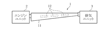
以下において、図1及び図2を参照しつつ、本実施例に係る排ガス発電ユニット1の構造について説明する。ここで、図1は、本実施例に係る排ガス発電ユニット1及びその他のユニットを含む概略上面図であり、特に排ガス発電ユニット1内部の構造を可視化して示している。また、図2は、本実施例に係る排ガス発電ユニット1及びその他のユニットを含む概略側面図である。
<Example 1>
Hereinafter, the structure of the exhaust gas
図1及び図2から分かるように、本実施例に係る排ガス発電ユニット1は、乗用自動車又はその他のエンジンを備える産業機器のエンジンユニット2と、排気ユニット3との間に設けられている。また、排ガス発電ユニット1は、エンジンユニット2と排気ユニット3とを接続する配管であって、エンジンユニット2から排出される排ガスの流路を構成する接続管11を有している。更に、排ガス発電ユニット1は、当該接続管11の内側の側面に設けられた6個の熱電変換モジュール12を有している。なお、熱電変換モジュール12の数量は、6個に限定されることなく、排ガス発電ユニット1の寸法、要求される発電量、及び熱電変換モジュール12の寸法に応じて適宜変更することができる。
As can be seen from FIGS. 1 and 2, the exhaust gas
図1から分かるように、接続管11においては、排ガスの流路の幅がエンジンユニット2との接続部から徐々に広がり、所望の幅寸法まで広がった後に、排気ユニット3の接続部に向けて徐々にその幅が狭くなっている。すなわち、接続管11は、エンジンユニット2との接続部においてその幅が一度広がるものの、エンジンユニット2側から排気ユニット3側に向けて徐々に排ガスの流路が絞られている。また、図2から分かるように、接続管11においては、排ガス流路の高さがエンジンユニット2側から排気ユニット3側に向けて徐々に小さくなっている。すなわち、接続管11の高さ方向においても、エンジンユニット2側から排気ユニット3側に向けて徐々に排ガスの流路が絞られている。以上のことから、接続管11の開口寸法は、エンジンユニット2の近傍において一度大きくなるものの、接続管11の全体的な構造としては、エンジンユニット2側から排気ユニット3側に向って、開口寸法が小さくなっていることになる。
As can be seen from FIG. 1, in the
このような、接続管11の形状により、エンジンユニット2から排出される高温の排ガスは、接続管11内で一度広がるものの、排気ユニット3に向けて収束するように流れることになる。すなわち、排ガスの流速は排気ユニット3に向うにつれて上昇することになる。換言するならば、接続管11のエンジンユニット2の近傍における排ガスの流速に比して、接続管11の排気ユニット3の近傍における排ガスの流速は増加することになる。従って、このような接続管11に形状は、排ガスの流速を上げる流速増加手段として機能することになる。なお、当該接続管11の形状により、排ガスの流束密度も、排気ユニット3側において増加することになる。
Due to the shape of the
接続管11の材料は、耐熱性を有し、且つ熱伝導性が比較的に低いものが使用される。これにより、排ガスの温度を低下させることがなくなり、熱電変換モジュール12における発電を効率よく行うことができる。
The connecting
熱電変換モジュール12は、例えば、電極を介して複数の熱電変換素子(p型半導体及びn型半導体)を電気的に直列に接続した公知のものを使用することができる。熱電変換モジュール12は、接続管11の内側の側面に並設されている。なお、熱電変換モジュール12の構造は限定されることなく、公知の種々のタイプのものを使用することができる。
As the
本実施例に係る排ガス発電ユニット1においては、上述した接続管11の形状により、排ガスの流路の下流側の流速が、上流側と比較して増加することになる。換言すると、排ガスの流路の下流側においては、接続管11の形状が端部に向けて絞られないものと比較して、熱流束が増加することになる。このため、排ガスの温度が下流側において低下する場合であっても、下流側に配設された熱電変換モジュール12に対して熱エネルギーを集中することができることから、下流側に配設された熱電変換モジュール12にも十分な熱量が供給されることになり、吸熱効率を向上させることができる。
In the exhaust gas
なお、本実施例においては、接続管11の開口形状は台形となっていたが、接続管11の開口形状が円形である円筒の管を使用してもよい。この場合であっても、排気ユニット3側に位置する接続管の端部を、エンジンユニット2側に位置する他端よりも絞るように形成(すなわち、開口寸法が小さくなるように)する必要がある。また、熱電変換モジュール12の設置箇所は、接続管11の内側の側面に限定されることなく、例えば、接続管11の内側の上面又は底面であってもよく、接続管11の内側表面から適宜選択することができる。
In the present embodiment, the opening shape of the connecting
<実施例2>
実施例1においては、接続管11の形状を流速増加手段として機能させていたが、排ガスを誘導する導風板(導風体、風導版とも称する)を設けて、当該風導版を流速増加手段として機能させてもよい。以下において、図3及び図4を参照しつつ、このような導風板を有する排ガス発電ユニット101を実施例2として説明する。ここで、図3は、本実施例に係る排ガス発電ユニット101及びその他のユニットを含む概略上面図であり、特に排ガス発電ユニット101内部の構造を可視化して示している。また、図4は、本実施例に係る排ガス発電ユニット101及びその他のユニットを含む概略側面図である。
<Example 2>
In the first embodiment, the shape of the connecting
図3及び図4から分かるように、本実施例に係る排ガス発電ユニット101も、乗用自動車又はその他のエンジンを備える産業機器のエンジンユニット102と、排気ユニット103との間に設けられている。また、排ガス発電ユニット101は、エンジンユニット102と排気ユニット103とを接続し、エンジンユニット102から排出される排ガスの流路を構成する接続管111を有している。更に、排ガス発電ユニット101は、当該接続管111の内側の側面に設けられた6個の熱電変換モジュール112を有している。
As can be seen from FIGS. 3 and 4, the exhaust gas
図3から分かるように、接続管111においては、排ガスの流路の幅がエンジンユニット2との接続部から徐々に広がり、所望の幅寸法まで広がると当該寸法が維持され、排気ユニット103との接続部の近傍から排気ユニット103に向けて徐々にその幅が狭くなっている。すなわち、接続管111は、エンジンユニット2との接続部においてその幅が一度広がり、且つ排気ユニット103との接続部においてその幅が徐々に狭くなるものの、接続管111の大部分においてその幅は一定に保たれている。また、図4から分かるように、接続管111においては、排ガス流路の高さがエンジンユニット102側から排気ユニット103側に向けて徐々に小さくなっている。すなわち、接続管111の高さ方向においては、エンジンユニット102側から排気ユニット103側に向けて徐々に排ガスの流路が絞られている。更に、接続管111の材料は、実施例1の接続管11と同様であり、耐熱性を有し且つ熱伝導性が比較的に低いものが使用される。
As can be seen from FIG. 3, in the connecting
熱電変換モジュール112は、実施例1の熱電変換モジュール12と同様に、電極を介して複数の熱電変換素子を電気的に直列に接続した公知のものを使用することができる。また、熱電変換モジュール112も、接続管111の内側の側面に並設されている。
The
図3に示すように、接続管111の内部には、3つの導風板121、122、123が設けられている。具体的には、排ガスの流路(すなわち、接続管111)の上流側から各熱電変換モジュール112に向って、各導風板が配設されている。
As shown in FIG. 3, three
導風板121は、最上流に位置する熱電変換モジュール112よりも更に上流側であって、接続管111の内側の側面近傍に配設されている。導風板121は、接続管111の内側の側面近傍から最上流に位置する熱電変換モジュール112(図3において左側に位置している)に向けて直線状に延在する2枚の板状部材121a、121bから構成されている。すなわち、導風板121は、板状部材121a、121bが当該中心線Oの近傍及びその周囲において離間した構造を有している。換言すると、導風板121は、接続管111と交差する領域に開口121cを備えることになる。
The
また、導風板122は、導風板121よりも内側、すなわち、その一部が導風板121によって囲まれるように配設されている。
導風板122は、接続管111の中心線O(図3において破線にて示す)の近傍から中流に位置する熱電変換モジュール112(図3において中央に位置している)に向けて直線状に延在する2枚の板状部材122a、122bから構成されている。すなわち、導風板122は、板状部材122a、122bが当該中心線Oの近傍において離間した構造を有している。換言すると、導風板122は、接続管111と交差する領域に開口122cを備えることになる。また、導風板122の長さは、導風板121の長さよりも大きくなっている。
Further, the
The
更に、導風板123は、導風板121、122よりも内側、すなわち、その一部が導風板121、122によって囲まれるように配設されている。導風板123は、接続管111の中心線Oの近傍から最下流に位置する熱電変換モジュール112(図3において右に位置している)向けて直線状に延在する2枚の板状部材123a、123bから構成されている。すなわち、導風板123も、導風板122と同様に、板状部材123a、123bが当該中心線Oの近傍において離間した構造を有している。換言すると、導風板123は、接続管111と交差する領域に開口123cを備えることになる。また、導風板123の長さは、導風板121、122の長さよりも大きくなっている。
Further, the
すなわち、導風板121、122、123のそれぞれは、排ガス流路の上流側から前記熱電変換モジュール112のそれぞれに向けて延在している。このような導風板121、122、123の構造及び配置から、上流側から流れる排ガス(図3において、最も太い矢印で示す)の一部は、接続管111と導風板121とよって形成された流路を経由して最上流に位置する熱電変換モジュール112に向けて誘導される。また、上流側から流れる排ガスの一部は、導風板121と導風板122によって形成された流路を経由して、最上流に位置する熱電変換モジュール112及び中央に位置する熱電変換モジュール112に向けて誘導される。更に、上流側から流れる排ガスの一部は、導風板122と導風板123によって形成された流路を経由して、中央に位置する熱電変換モジュール112及び最下流に位置する熱電変換モジュール112に向けて誘導される。従って、エンジンユニット102から排出された排ガスは、導風板121、122、123に沿って接続管111の両側部に誘導され、接続管111の内側の側面に設けられた熱電変換モジュール112に向けて進むことになり、当該熱電変換モジュール112において優れた熱エネルギー効率で吸熱されることになる。
That is, each of the
また、このような導風板121、122、123により、エンジンユニット2から排出される高温の排ガスは接続管111内の上流側で一度広がるものの、導風板121、122、123の設置箇所及びこれより下流側においては接続管111の側部に向けて収束するように流れることになる。すなわち、排ガスの流速は排気ユニット103に向うにつれて上昇することになる。換言するならば、接続管111のエンジンユニット102の近傍における排ガスの流速に比して、接続管111の排気ユニット103の近傍における排ガスの流速は増加することになる。従って、このような導風板121、122、123は、排ガスの流速を上げる流速増加手段として機能することになる。なお、当該導風板121、122、123により、排ガスの流束密度も、排気ユニット103側において増加することになる。
Moreover, although the high temperature exhaust gas discharged | emitted from the
本実施例に係る排ガス発電ユニット101においては、上述した導風板121、122、123により、排ガスの流路の下流側の流速が、上流側と比較して増加することになる。換言すると、排ガスの流路の下流側においては、導風板121、122、123が存在しないものと比較して、熱流束が増加することになる。このため、排ガスの温度が下流側において低下する場合であっても、下流側に配設された熱電変換モジュール112に対して熱エネルギーを集中することができることから、下流側に配設された熱電変換モジュール112にも十分な熱量が供給されることになり、吸熱効率を向上させることができる。
In the exhaust gas
なお、本実施例においては、導風板121、122、123のそれぞれが2枚の板状部材から構成されていたが、これに限定されることなく、例えば1枚の板状部材を湾曲及び屈曲させ、必要に応じて開口を形成したものから構成されていてもよく、2枚以上の板状部材から構成されてもよい。また、本実施例において、導風板121、122、123は接続管111の両側部に排ガスを誘導していたが、熱電変換モジュール112が接続管111の上面及び底面にも設けられる場合には、排ガスを接続管111の上面及び底面に誘導するような構造を備えていてもよい。このような場合には、接続管111の形状は角筒状であってもよい。更に、接続管111の外形は、実施例1の接続管11のように、一端(すなわち、排ガスの流路の下流側)に向けて絞られていてもよい。そして、各導風板を構成する各板状部材は直線状ではなく、湾曲して形状を有してもよい。また、導風板123については、開口123cが形成されていなくてもよい。これにより、エンジンユニット102から排出されたすべての排ガスが、接続管111の両側部に誘導されることになり、更なる発電効率の向上を図ることが可能になる。
In this embodiment, each of the
<実施例3>
実施例2においては、3つの導風板121、122、123を流速増加手段として機能させていたが、1つの導風板を流速増加手段として機能させてもよい。以下において、図5及び図6を参照しつつ、このような導風板を有する排ガス発電ユニット201を実施例3として説明する。ここで、図5は、本実施例に係る排ガス発電ユニット201及びその他のユニットを含む概略上面図であり、特に排ガス発電ユニット201内部の構造を可視化して示している。また、図6は、本実施例に係る排ガス発電ユニット201及びその他のユニットを含む概略側面図である。
<Example 3>
In the second embodiment, the three
図5及び図6から分かるように、本実施例に係る排ガス発電ユニット201も、乗用自動車又はその他のエンジンを備える産業機器のエンジンユニット202と、排気ユニット203との間に設けられている。また、排ガス発電ユニット201は、実施例2の排ガス発電ユニット101と同様に、接続管211及び当該接続管211内側の側面に設けられた6個の熱電変換モジュール212を有している。なお、接続管211の形状及び材料は、実施例2の接続管111と同一であり、熱電変換モジュール212も実施例2の熱電変換モジュール112と同一であるため、これらの説明は省略する。
As can be seen from FIGS. 5 and 6, the exhaust gas
図5に示すように、接続管211の内部には、導風板224が設けられている。具体的には、排ガスの流路(すなわち、接続管211)の中央から下流側において、三角柱状の導風板224が配設されている。導風板は、接続管211の中心線O(図5において破線にて示す)から接続管211の内側の側面に向けて延在する側面224a、224bを有している。すなわち、導風板224は、接続管211のエンジンユニット202側から排気ユニット203側に向って、排ガスの流路を狭くするような構造体である。なお、導風板224の形状は、三角柱状に限定されることなく、排ガスの流路を下流に向って徐々に狭くすることができれば、その他の形状の構造体であってもよく、また、接続管211の開口形状によっても適宜変更することができる。
As shown in FIG. 5, an
このような、導風板224の形状により、エンジンユニット202から排出される高温の排ガスは、接続管211内で一度広がるものの、排気ユニット203に向けて収束するように流れることになる。すなわち、排ガスの流速は排気ユニット203に向うにつれて上昇することになる。換言するならば、接続管211のエンジンユニット202の近傍における排ガスの流速に比して、接続管211の排気ユニット203の近傍における排ガスの流速は増加することになる。従って、このような導風板224の形状は、排ガスの流速を上げる流速増加手段として機能することになる。なお、当該導風板224の形状により、排ガスの流束密度も、排気ユニット203側において増加することになる。
With such a shape of the
本実施例に係る排ガス発電ユニット201においては、上述した導風板224の形状により、排ガスの流路の下流側の流速が、上流側と比較して増加することになる。換言すると、排ガスの流路の下流側においては、導風板224が設けられていないものと比較して、熱流束が増加することになる。このため、排ガスの温度が下流側において低下する場合であっても、下流側に配設された熱電変換モジュール212に対して熱エネルギーを集中することができることから、下流側に配設された熱電変換モジュール212にも十分な熱量が供給されることになり、吸熱効率を向上させることができる。
In the exhaust gas
1 排ガス発電ユニット
2 エンジンユニット
3 排気ユニット
11 接続管
12 熱電変換モジュール
101 排ガス発電ユニット
102 エンジンユニット
103 排気ユニット
111 接続管
112 熱電変換モジュール
121 導風板
122 導風板
123 導風板
201 排ガス発電ユニット
202 エンジンユニット
203 排気ユニット
211 接続管
212 熱電変換モジュール
224 導風板
DESCRIPTION OF
Claims (5)
前記エンジンユニットと前記排気ユニットを接続し、前記エンジンユニットから排出される排ガスの流路を形成する接続管と、
前記接続管の内側表面であって前記エンジンユニットの近傍及び前記排気ユニットの近傍に設けられた複数の熱電変換モジュールと、
前記接続管の前記エンジンユニットの近傍における前記排ガスの流速に比して、前記接続管の前記排気ユニットの近傍における前記排ガスの流速を上げる流速増加手段と、を有する排ガス発電ユニット。 An exhaust gas power generation unit provided between the engine unit and the exhaust unit,
A connecting pipe connecting the engine unit and the exhaust unit, and forming a flow path of exhaust gas discharged from the engine unit;
A plurality of thermoelectric conversion modules provided on the inner surface of the connection pipe and in the vicinity of the engine unit and in the vicinity of the exhaust unit;
An exhaust gas power generation unit comprising: a flow rate increasing means for increasing the flow rate of the exhaust gas in the vicinity of the exhaust unit of the connection pipe as compared to the flow rate of the exhaust gas in the vicinity of the engine unit of the connection pipe.
Priority Applications (9)
| Application Number | Priority Date | Filing Date | Title |
|---|---|---|---|
| JP2016058571A JP6675899B2 (en) | 2016-03-23 | 2016-03-23 | Exhaust gas power generation unit |
| CA3015618A CA3015618C (en) | 2016-03-22 | 2017-03-21 | Thermoelectric conversion unit, thermoelectric conversion module, and exhaust-gas electricity generation unit |
| KR1020207008181A KR102261839B1 (en) | 2016-03-22 | 2017-03-21 | Exhaust gas power generation unit |
| US16/087,590 US20190109271A1 (en) | 2016-03-22 | 2017-03-21 | Thermoelectric conversion unit, thermoelectric conversion module, and exhaust-gas electricity generation unit |
| PCT/JP2017/011249 WO2017164180A1 (en) | 2016-03-22 | 2017-03-21 | Thermoelectric conversion unit, thermoelectric conversion module, and exhaust gas power generation unit |
| KR1020187025820A KR20180111947A (en) | 2016-03-22 | 2017-03-21 | A thermoelectric conversion unit, a thermoelectric conversion module, and an exhaust gas power generation unit |
| CN201780018192.0A CN108886082B (en) | 2016-03-22 | 2017-03-21 | Thermoelectric conversion unit, thermoelectric conversion module, and exhaust gas power generation unit |
| EP17770222.2A EP3435430A4 (en) | 2016-03-22 | 2017-03-21 | Thermoelectric conversion unit, thermoelectric conversion module, and exhaust gas power generation unit |
| US16/868,487 US11282999B2 (en) | 2016-03-22 | 2020-05-06 | Thermoelectric conversion unit, thermoelectric conversion module, and exhaust-gas electricity generation unit |
Applications Claiming Priority (1)
| Application Number | Priority Date | Filing Date | Title |
|---|---|---|---|
| JP2016058571A JP6675899B2 (en) | 2016-03-23 | 2016-03-23 | Exhaust gas power generation unit |
Publications (2)
| Publication Number | Publication Date |
|---|---|
| JP2017172437A true JP2017172437A (en) | 2017-09-28 |
| JP6675899B2 JP6675899B2 (en) | 2020-04-08 |
Family
ID=59971225
Family Applications (1)
| Application Number | Title | Priority Date | Filing Date |
|---|---|---|---|
| JP2016058571A Active JP6675899B2 (en) | 2016-03-22 | 2016-03-23 | Exhaust gas power generation unit |
Country Status (1)
| Country | Link |
|---|---|
| JP (1) | JP6675899B2 (en) |
Citations (6)
| Publication number | Priority date | Publication date | Assignee | Title |
|---|---|---|---|---|
| JPH10290590A (en) * | 1997-04-15 | 1998-10-27 | Honda Motor Co Ltd | Exhaust heat energy collector |
| JP2008078587A (en) * | 2006-09-25 | 2008-04-03 | Denso Corp | Fin for heat exchange |
| JP2010219255A (en) * | 2009-03-16 | 2010-09-30 | Yanmar Co Ltd | Thermoelectric power generation device |
| JP2010275872A (en) * | 2009-05-26 | 2010-12-09 | Isuzu Motors Ltd | Thermoelectric unit |
| JP2014105605A (en) * | 2012-11-26 | 2014-06-09 | Toyota Motor Corp | Thermoelectric generator |
| JP2014225509A (en) * | 2013-05-15 | 2014-12-04 | スズキ株式会社 | Waste heat power generator |
-
2016
- 2016-03-23 JP JP2016058571A patent/JP6675899B2/en active Active
Patent Citations (6)
| Publication number | Priority date | Publication date | Assignee | Title |
|---|---|---|---|---|
| JPH10290590A (en) * | 1997-04-15 | 1998-10-27 | Honda Motor Co Ltd | Exhaust heat energy collector |
| JP2008078587A (en) * | 2006-09-25 | 2008-04-03 | Denso Corp | Fin for heat exchange |
| JP2010219255A (en) * | 2009-03-16 | 2010-09-30 | Yanmar Co Ltd | Thermoelectric power generation device |
| JP2010275872A (en) * | 2009-05-26 | 2010-12-09 | Isuzu Motors Ltd | Thermoelectric unit |
| JP2014105605A (en) * | 2012-11-26 | 2014-06-09 | Toyota Motor Corp | Thermoelectric generator |
| JP2014225509A (en) * | 2013-05-15 | 2014-12-04 | スズキ株式会社 | Waste heat power generator |
Also Published As
| Publication number | Publication date |
|---|---|
| JP6675899B2 (en) | 2020-04-08 |
Similar Documents
| Publication | Publication Date | Title |
|---|---|---|
| JP2009152455A (en) | Semiconductor cooling structure | |
| JP6303755B2 (en) | Exhaust heat exchanger | |
| JP5939143B2 (en) | Thermoelectric generator | |
| JP2015115590A (en) | Thermoelectric conversion module | |
| US9234448B2 (en) | Muffler | |
| JP6601317B2 (en) | Thermoelectric generator | |
| KR101435667B1 (en) | Thermoelectric Power Generator | |
| JP2008091700A (en) | Semiconductor device | |
| JP2016025271A (en) | Thermoelectric conversion device | |
| JP2010219255A (en) | Thermoelectric power generation device | |
| JP2017172437A (en) | Exhaust gas power generation unit | |
| US11282999B2 (en) | Thermoelectric conversion unit, thermoelectric conversion module, and exhaust-gas electricity generation unit | |
| KR101676882B1 (en) | Thermoelectric element module for vehicles | |
| JP2016157578A (en) | Cooling structure of heating element | |
| JP2013048151A (en) | Semiconductor cooling device for vehicle | |
| JP6020434B2 (en) | Thermoelectric generator | |
| JP2006278735A (en) | Cooling device | |
| KR102606271B1 (en) | Radiation pin for thermoelectic generation and radiation assembly including the same | |
| JP6376511B2 (en) | Thermoelectric converter | |
| EP4167464A1 (en) | Thermal power generation unit | |
| JP2017174900A (en) | Thermoelectric conversion unit and thermoelectric conversion module | |
| JP2018010907A (en) | Thermoelectric conversion device and thermoelectric conversion method | |
| KR20240047537A (en) | Heat exchange apparatus for thermoelectric power generation | |
| JP6414187B2 (en) | Power converter | |
| TWI586006B (en) | Thermoelectric module |
Legal Events
| Date | Code | Title | Description |
|---|---|---|---|
| A621 | Written request for application examination |
Free format text: JAPANESE INTERMEDIATE CODE: A621 Effective date: 20190221 |
|
| A131 | Notification of reasons for refusal |
Free format text: JAPANESE INTERMEDIATE CODE: A131 Effective date: 20191113 |
|
| A521 | Request for written amendment filed |
Free format text: JAPANESE INTERMEDIATE CODE: A523 Effective date: 20200109 |
|
| TRDD | Decision of grant or rejection written | ||
| A01 | Written decision to grant a patent or to grant a registration (utility model) |
Free format text: JAPANESE INTERMEDIATE CODE: A01 Effective date: 20200219 |
|
| A61 | First payment of annual fees (during grant procedure) |
Free format text: JAPANESE INTERMEDIATE CODE: A61 Effective date: 20200311 |
|
| R150 | Certificate of patent or registration of utility model |
Ref document number: 6675899 Country of ref document: JP Free format text: JAPANESE INTERMEDIATE CODE: R150 |
|
| R250 | Receipt of annual fees |
Free format text: JAPANESE INTERMEDIATE CODE: R250 |
|
| S531 | Written request for registration of change of domicile |
Free format text: JAPANESE INTERMEDIATE CODE: R313532 |
|
| R350 | Written notification of registration of transfer |
Free format text: JAPANESE INTERMEDIATE CODE: R350 |
|
| R250 | Receipt of annual fees |
Free format text: JAPANESE INTERMEDIATE CODE: R250 |