JP2017170571A - Robot, robot control apparatus, and robot system - Google Patents
Robot, robot control apparatus, and robot system Download PDFInfo
- Publication number
- JP2017170571A JP2017170571A JP2016059673A JP2016059673A JP2017170571A JP 2017170571 A JP2017170571 A JP 2017170571A JP 2016059673 A JP2016059673 A JP 2016059673A JP 2016059673 A JP2016059673 A JP 2016059673A JP 2017170571 A JP2017170571 A JP 2017170571A
- Authority
- JP
- Japan
- Prior art keywords
- robot
- information
- conversion information
- coordinate system
- posture
- Prior art date
- Legal status (The legal status is an assumption and is not a legal conclusion. Google has not performed a legal analysis and makes no representation as to the accuracy of the status listed.)
- Withdrawn
Links
Images


Classifications
-
- G—PHYSICS
- G05—CONTROLLING; REGULATING
- G05B—CONTROL OR REGULATING SYSTEMS IN GENERAL; FUNCTIONAL ELEMENTS OF SUCH SYSTEMS; MONITORING OR TESTING ARRANGEMENTS FOR SUCH SYSTEMS OR ELEMENTS
- G05B19/00—Programme-control systems
- G05B19/02—Programme-control systems electric
- G05B19/18—Numerical control [NC], i.e. automatically operating machines, in particular machine tools, e.g. in a manufacturing environment, so as to execute positioning, movement or co-ordinated operations by means of programme data in numerical form
- G05B19/408—Numerical control [NC], i.e. automatically operating machines, in particular machine tools, e.g. in a manufacturing environment, so as to execute positioning, movement or co-ordinated operations by means of programme data in numerical form characterised by data handling or data format, e.g. reading, buffering or conversion of data
- G05B19/4086—Coordinate conversions; Other special calculations
-
- B—PERFORMING OPERATIONS; TRANSPORTING
- B25—HAND TOOLS; PORTABLE POWER-DRIVEN TOOLS; MANIPULATORS
- B25J—MANIPULATORS; CHAMBERS PROVIDED WITH MANIPULATION DEVICES
- B25J9/00—Programme-controlled manipulators
- B25J9/16—Programme controls
- B25J9/1628—Programme controls characterised by the control loop
- B25J9/1643—Programme controls characterised by the control loop redundant control
-
- B—PERFORMING OPERATIONS; TRANSPORTING
- B25—HAND TOOLS; PORTABLE POWER-DRIVEN TOOLS; MANIPULATORS
- B25J—MANIPULATORS; CHAMBERS PROVIDED WITH MANIPULATION DEVICES
- B25J9/00—Programme-controlled manipulators
- B25J9/16—Programme controls
- B25J9/1694—Programme controls characterised by use of sensors other than normal servo-feedback from position, speed or acceleration sensors, perception control, multi-sensor controlled systems, sensor fusion
- B25J9/1697—Vision controlled systems
Abstract
Description
この発明は、ロボット、ロボット制御装置、及びロボットシステムに関する。 The present invention relates to a robot, a robot control device, and a robot system.
撮像部により撮像された撮像画像に基づいてロボットに所定の作業を行わせる技術の研究や開発が行われている。 Research and development of a technique for causing a robot to perform a predetermined operation based on a captured image captured by an imaging unit has been performed.
これに関し、目標点に対してパラメーターを適用して座標変換を行うことでロボットの動作を制御するロボットの動作制御装置において、ロボットの動作空間を複数の領域に分割し、分割された動作空間毎に測定点を設定してパラメーターを導出し、導出された動作空間毎のパラメーターのうち目標点が属する動作空間のパラメーターを選択し、目標点に対して選択されたパラメーターを適用して座標変換を行うことでロボットの動作を制御するロボットの動作制御装置が知られている(特許文献1参照)。 In this regard, in a robot motion control device that controls robot motion by applying coordinate transformation to a target point and performing coordinate transformation, the robot motion space is divided into a plurality of regions, and each of the divided motion spaces is divided. The measurement point is set to, the parameter is derived, the parameter of the motion space to which the target point belongs is selected from the parameters of the derived motion space, and the coordinate transformation is applied by applying the selected parameter to the target point. 2. Description of the Related Art A robot motion control device that controls the motion of a robot by performing it is known (see Patent Document 1).
しかしながら、このような動作制御装置では、目標点においてロボットのTCPの姿勢を変化させずにロボットの各関節の回転角を変化させた場合、当該回転角を変化させる前の当該TCPの位置及び姿勢と、当該回転角を変化させた後の当該TCPの位置及び姿勢とが、ロボットを構成する各部材の剛性等による誤差によってずれてしまう場合があった。その結果、当該動作制御装置では、ロボットに行わせる作業の精度を向上させることが困難な場合があった。 However, in such an operation control apparatus, when the rotation angle of each joint of the robot is changed without changing the posture of the robot TCP at the target point, the position and posture of the TCP before the rotation angle is changed. In some cases, the position and posture of the TCP after changing the rotation angle may be shifted due to an error due to the rigidity of each member constituting the robot. As a result, in the motion control device, it may be difficult to improve the accuracy of work performed by the robot.
上記課題の少なくとも一つを解決するために本発明の一態様は、撮像部により撮像された撮像画像上の位置及び姿勢を表す撮像部座標系における対象物の位置及び姿勢を表す第1情報を、第1座標系における前記対象物の位置及び姿勢を表す第2情報に変換する変換情報が複数あり、前記複数の前記変換情報の中から1つの前記変換情報を対象変換情報として選択し、選択した当該変換情報に基づいて所定の作業を行う、ロボットである。
この構成により、ロボットは、撮像部により撮像された撮像画像上の位置及び姿勢を表す撮像部座標系における対象物の位置及び姿勢を表す第1情報を、第1座標系における当該対象物の位置及び姿勢を表す第2情報に変換する変換情報が複数あり、複数の変換情報の中から1つの変換情報を対象変換情報として選択し、選択した当該変換情報に基づいて所定の作業を行う。これにより、ロボットは、ロボットが行う作業の精度を向上させることができる。
In order to solve at least one of the above problems, according to one aspect of the present invention, first information representing the position and orientation of an object in an imaging unit coordinate system representing a position and orientation on a captured image captured by an imaging unit is obtained. , There are a plurality of conversion information to be converted into second information representing the position and orientation of the object in the first coordinate system, and one of the plurality of conversion information is selected as the target conversion information and selected The robot performs a predetermined operation based on the converted information.
With this configuration, the robot transmits the first information representing the position and orientation of the target in the imaging unit coordinate system representing the position and orientation on the captured image captured by the imaging unit to the position of the target in the first coordinate system. There are a plurality of pieces of conversion information to be converted into the second information representing the posture, and one piece of conversion information is selected as the target conversion information from the plurality of pieces of conversion information, and a predetermined operation is performed based on the selected conversion information. Thereby, the robot can improve the precision of the operation | work which a robot performs.
また、本発明の他の態様は、ロボットにおいて、前記変換情報には、前記撮像部座標系における位置を示す位置情報が対応付けられており、前記変換情報に対応付けられた前記位置情報が示す位置と、前記撮像画像から検出された前記対象物の前記撮像部座標系における位置とが最も近い前記変換情報を前記対象変換情報として選択する、構成が用いられてもよい。
この構成により、ロボットは、変換情報に対応付けられた位置情報が示す位置と、撮像画像から検出された対象物の撮像部座標系における位置とが最も近い変換情報を対象変換情報として選択する。これにより、ロボットは、位置情報が対応付けられた変換情報に基づいて、ロボットが行う作業の精度を向上させることができる。
In another aspect of the present invention, in the robot, the conversion information is associated with position information indicating a position in the imaging unit coordinate system, and the position information associated with the conversion information indicates the position information. A configuration may be used in which the conversion information having the closest position and the position of the object detected from the captured image in the image capturing unit coordinate system is selected as the object conversion information.
With this configuration, the robot selects, as the target conversion information, the conversion information in which the position indicated by the position information associated with the conversion information is closest to the position of the target object detected from the captured image in the imaging unit coordinate system. Thereby, the robot can improve the accuracy of the work performed by the robot based on the conversion information associated with the position information.
また、本発明の他の態様は、ロボットにおいて、前記変換情報には更に、前記撮像部座標系における姿勢を示す姿勢情報が対応付けられており、前記変換情報に対応付けられた前記姿勢情報が示す姿勢と、前記撮像画像から検出された前記対象物の前記撮像部座標系における姿勢とが最も近い前記変換情報を前記対象変換情報として選択する、構成が用いられてもよい。
この構成により、ロボットは、変換情報には更に、撮像部座標系における姿勢を示す姿勢情報が対応付けられており、変換情報に対応付けられた姿勢情報が示す姿勢と、撮像画像から検出された対象物の撮像部座標系における姿勢とが最も近い変換情報を対象変換情報として選択する。これにより、ロボットは、姿勢情報が対応付けられた変換情報に基づいて、ロボットが行う作業の精度を向上させることができる。
In another aspect of the present invention, in the robot, the conversion information is further associated with posture information indicating a posture in the imaging unit coordinate system, and the posture information associated with the conversion information is A configuration may be used in which the conversion information that is closest to the posture shown and the posture of the object detected from the captured image in the imaging unit coordinate system is selected as the target conversion information.
With this configuration, the robot further associates the conversion information with the posture information indicating the posture in the imaging unit coordinate system, and is detected from the posture indicated by the posture information associated with the conversion information and the captured image. Conversion information that is closest to the posture of the target in the imaging unit coordinate system is selected as target conversion information. Thereby, the robot can improve the accuracy of the work performed by the robot based on the conversion information associated with the posture information.
また、本発明の他の態様は、ロボットにおいて、7つ以上の関節を有し、前記変換情報には更に、前記ロボットが備える関節のうちの3つの旋回関節を結ぶことによって形成される三角形を含む平面である対象平面の基準平面に対する角度である冗長回転角を示す冗長回転角情報が対応付けられており、前記変換情報に対応付けられた前記冗長回転角情報が示す前記冗長回転角と、予め入力された前記冗長回転角とが最も近い前記変換情報を前記対象変換情報として選択する、構成が用いられてもよい。
この構成により、ロボットは、変換情報に対応付けられた冗長回転角情報が示す冗長回転角と、予め入力された冗長回転角とが最も近い変換情報を対象変換情報として選択する。これにより、ロボットは、冗長回転角情報が対応付けられた変換情報に基づいて、ロボットが行う作業の精度を向上させることができる。
According to another aspect of the present invention, the robot has seven or more joints, and the conversion information further includes a triangle formed by connecting three swivel joints of the joints of the robot. Redundant rotation angle information indicating a redundant rotation angle that is an angle with respect to a reference plane of a target plane that is a plane that includes the redundant rotation angle information that is associated with the conversion information, and the redundant rotation angle information that is associated with the conversion information, A configuration may be used in which the conversion information closest to the redundant rotation angle input in advance is selected as the target conversion information.
With this configuration, the robot selects, as target conversion information, conversion information that is closest to the redundant rotation angle indicated by the redundant rotation angle information associated with the conversion information and the redundant rotation angle input in advance. Thereby, the robot can improve the precision of the operation | work which a robot performs based on the conversion information matched with redundant rotation angle information.
また、本発明の他の態様は、ロボットにおいて、前記変換情報には更に、前記ロボットが備える各関節のうちの回転角が互いに180°異なる2つの回転角のいずれであっても制御点の位置及び姿勢を第1位置及び第1姿勢と一致させることが可能な関節であるフリップ可能関節の回転角を、互いに180°異なる2つの回転角のうちの小さい方の回転角と大きい方の回転角とのいずれにするかを示すポーズ情報が対応付けられており、前記変換情報に対応付けられた前記ポーズ情報と、予め入力された前記ポーズ情報とが一致する前記変換情報を前記対象変換情報として選択する、構成が用いられてもよい。
この構成により、ロボットは、変換情報に対応付けられたポーズ情報と、予め入力されたポーズ情報とが一致する変換情報を対象変換情報として選択する。これにより、ロボットは、ポーズ情報が対応付けられた変換情報に基づいて、ロボットが行う作業の精度を向上させることができる。
According to another aspect of the present invention, in the robot, the conversion information further includes the position of the control point regardless of any of two rotation angles that are 180 ° different from each other. And the rotation angle of the flippable joint, which is a joint capable of matching the posture with the first position and the first posture, is the smaller rotation angle and the larger rotation angle of two rotation angles different from each other by 180 °. Pose information indicating which of the pose information and the pose information associated with the conversion information matches the conversion information in which the pose information input in advance is the target conversion information. The configuration that you choose may be used.
With this configuration, the robot selects, as target conversion information, conversion information in which the pose information associated with the conversion information matches the pose information input in advance. Thereby, the robot can improve the accuracy of the work performed by the robot based on the conversion information associated with the pose information.
また、本発明の他の態様は、ロボットにおいて、前記ロボットが前記作業を行う領域を複数の分割領域に分割し、前記分割領域に応じた複数の測定点毎に1以上の前記変換情報を生成する、構成が用いられてもよい。
この構成により、ロボットは、ロボットが作業を行う領域を複数の分割領域に分割し、分割領域に応じた複数の測定点毎に1以上の変換情報を生成する。これにより、ロボットは、分割領域に応じた複数の測定点毎に生成された1以上の変換情報に基づいて、ロボットが行う作業の精度を向上させることができる。
According to another aspect of the present invention, in a robot, an area where the robot performs the work is divided into a plurality of divided areas, and one or more pieces of conversion information are generated for each of a plurality of measurement points corresponding to the divided areas. A configuration may be used.
With this configuration, the robot divides an area in which the robot performs work into a plurality of divided areas, and generates one or more pieces of conversion information for each of a plurality of measurement points corresponding to the divided areas. Thereby, the robot can improve the precision of the operation | work which a robot performs based on the 1 or more conversion information produced | generated for every some measurement point according to a division area.
また、本発明の他の態様は、ロボットにおいて、前記測定点毎に、前記測定点に前記ロボットの制御点を一致させてから前記変換情報を生成する処理を実行する、構成が用いられてもよい。
この構成により、ロボットは、測定点毎に、測定点にロボットの制御点を一致させてから変換情報を生成する処理を実行する。これにより、ロボットは、測定点毎に実行された処理であって変換情報を生成する処理によって生成された変換情報に基づいて、ロボットが行う作業の精度を向上させることができる。
Further, according to another aspect of the present invention, in the robot, a configuration may be used in which the conversion information is generated for each measurement point after the control point of the robot is matched with the measurement point. Good.
With this configuration, for each measurement point, the robot executes a process of generating conversion information after matching the control point of the robot with the measurement point. Thereby, the robot can improve the accuracy of the work performed by the robot based on the conversion information generated by the process executed for each measurement point and generating the conversion information.
また、本発明の他の態様は、ロボットにおいて、前記処理は、前記ロボットの制御点の前記第1座標系における位置を保持したまま、前記制御点の前記第1座標系における姿勢を変更する毎に前記変換情報を生成する処理である、構成が用いられてもよい。
この構成により、ロボットは、制御点の第1座標系における位置を保持したまま、制御点の第1座標系における姿勢を変更する毎に変換情報を生成する処理である。これにより、ロボットは、測定点毎に、測定点にロボットの制御点を一致させた状態を保持したまま、制御点の第1座標系における姿勢を変更する毎に変換情報を生成する処理によって生成された変換情報に基づいて、ロボットが行う作業の精度を向上させることができる。
According to another aspect of the present invention, in the robot, each time the process changes the posture of the control point in the first coordinate system while maintaining the position of the control point of the robot in the first coordinate system. A configuration that is a process of generating the conversion information may be used.
With this configuration, the robot generates conversion information each time the posture of the control point in the first coordinate system is changed while maintaining the position of the control point in the first coordinate system. Thus, the robot generates the conversion information for each measurement point every time the control point of the control point in the first coordinate system is changed while maintaining the state where the control point of the robot coincides with the measurement point. Based on the converted information, the accuracy of the work performed by the robot can be improved.
また、本発明の他の態様は、ロボットにおいて、7つ以上の関節を有し、前記処理は、前記制御点の前記第1座標系における位置を保持したまま、前記ロボットが備える関節のうちの3つの旋回関節を結ぶことによって形成される三角形を含む平面である対象平面の基準平面に対する角度である冗長回転角を変更する毎に前記変換情報を生成する処理である、構成が用いられてもよい。
この構成により、ロボットは、制御点の第1座標系における位置を保持したまま、ロボットが備える関節のうちの3つの旋回関節を結ぶことによって形成される三角形を含む平面である対象平面の基準平面に対する角度である冗長回転角を変更する毎に変換情報を生成する処理を実行する。これにより、ロボットは、測定点毎に、測定点にロボットの制御点を一致させた状態を保持したまま、冗長回転角を変更する毎に変換情報を生成する処理によって生成された変換情報に基づいて、ロボットが行う作業の精度を向上させることができる。
Further, according to another aspect of the present invention, the robot has seven or more joints, and the processing includes the joints included in the robot while maintaining the position of the control point in the first coordinate system. Even if a configuration is used, which is a process for generating the conversion information every time the redundant rotation angle that is an angle with respect to a reference plane of a target plane that is a plane including a triangle formed by connecting three swivel joints is changed. Good.
With this configuration, the robot can maintain the position of the control point in the first coordinate system, and the reference plane of the target plane that is a plane including a triangle formed by connecting three swivel joints of the joints included in the robot. Each time the redundant rotation angle that is an angle with respect to is changed, a process for generating conversion information is executed. Thereby, the robot is based on the conversion information generated by the process of generating the conversion information every time the redundant rotation angle is changed while maintaining the state in which the control point of the robot coincides with the measurement point for each measurement point. Thus, the accuracy of the work performed by the robot can be improved.
また、本発明の他の態様は、ロボットにおいて、前記処理は、前記制御点の前記第1座標系における位置を保持したまま、前記ロボットが備える各関節のうちの回転角が互いに180°異なる2つの回転角のいずれであっても制御点の位置及び姿勢を第1位置及び第1姿勢と一致させることが可能な関節であるフリップ可能関節の回転角を、互いに180°異なる2つの回転角のうちの小さい方の回転角と大きい方の回転角とのいずれかに変更する毎に前記変換情報を生成する処理である、構成が用いられてもよい。
この構成により、ロボットは、ロボットが備える各関節のうちの回転角が互いに180°異なる2つの回転角のいずれであっても制御点の位置及び姿勢を第1位置及び第1姿勢と一致させることが可能な関節であるフリップ可能関節の回転角を、互いに180°異なる2つの回転角のうちの小さい方の回転角と大きい方の回転角とのいずれかに変更する毎に変換情報を生成する処理を実行する。これにより、ロボットは、測定点毎に、測定点にロボットの制御点を一致させた状態を保持したまま、フリップ可能関節の回転角を変更する毎に変換情報を生成する処理によって生成された変換情報に基づいて、ロボットが行う作業の精度を向上させることができる。
According to another aspect of the present invention, in the robot, the processing includes a step in which the rotation angles of the joints of the robot are 180 ° different from each other while maintaining the position of the control point in the
With this configuration, the robot can match the position and posture of the control point with the first position and the first posture regardless of the two rotation angles that are 180 ° different from each other. Conversion information is generated every time the rotation angle of a flip-capable joint, which is a joint capable of being changed, is changed to one of the smaller rotation angle and the larger rotation angle of two rotation angles different from each other by 180 °. Execute the process. As a result, for each measurement point, the robot generates conversion information every time it changes the rotation angle of the flippable joint while maintaining the state in which the robot control point coincides with the measurement point. Based on the information, the accuracy of the work performed by the robot can be improved.
また、本発明の他の態様は、ロボットにおいて、前記変換情報には更に、前記撮像部の前記第1座標系における位置及び姿勢である撮像位置姿勢を示す撮像位置姿勢情報が対応付けられており、前記変換情報に対応付けられた前記撮像位置姿勢情報が示す前記撮像位置姿勢と、予め入力された前記撮像位置姿勢とが一致する前記変換情報を前記対象変換情報として選択する、構成が用いられてもよい。
この構成により、ロボットは、変換情報に対応付けられた撮像位置姿勢情報が示す撮像位置姿勢と、予め入力された撮像位置姿勢とが一致する変換情報を対象変換情報として選択する。これにより、ロボットは、撮像位置姿勢情報が対応付けられた変換情報に基づいて、ロボットが行う作業の精度を向上させることができる。
According to another aspect of the present invention, in the robot, the conversion information is further associated with imaging position / orientation information indicating an imaging position / orientation that is a position and orientation of the imaging unit in the first coordinate system. A configuration is used in which the conversion information in which the imaging position and orientation indicated by the imaging position and orientation information associated with the conversion information matches the imaging position and orientation input in advance is selected as the target conversion information. May be.
With this configuration, the robot selects, as target conversion information, conversion information in which the imaging position and orientation indicated by the imaging position and orientation information associated with the conversion information match the imaging position and orientation input in advance. Thereby, the robot can improve the accuracy of the work performed by the robot based on the conversion information associated with the imaging position and orientation information.
また、本発明の他の態様は、ロボットにおいて、前記第1情報は、第1行列であり、前記第2情報は、第2行列であり、前記変換情報は、変換行列であり、前記第1座標系は、ロボット座標系である、構成が用いられてもよい。
この構成により、ロボットは、撮像部により撮像された撮像画像上の位置及び姿勢を表す撮像部座標系における対象物の位置及び姿勢を表す第1行列を、ロボット座標系における当該対象物の位置及び姿勢を表す第2行列に変換する変換行列が複数あり、複数の変換行列の中から1つの変換行列を対象変換行列として選択し、選択した当該変換行列に基づいて所定の作業を行う。これにより、ロボットは、ロボットが行う作業の精度を向上させることができる。
According to another aspect of the present invention, in the robot, the first information is a first matrix, the second information is a second matrix, the conversion information is a conversion matrix, and the first information is the first matrix. A configuration in which the coordinate system is a robot coordinate system may be used.
With this configuration, the robot uses the first matrix representing the position and orientation of the object in the imaging unit coordinate system that represents the position and orientation on the captured image captured by the imaging unit as the position of the object in the robot coordinate system and There are a plurality of transformation matrices to be transformed into the second matrix representing the posture, and one transformation matrix is selected as a target transformation matrix from the plurality of transformation matrices, and a predetermined operation is performed based on the selected transformation matrix. Thereby, the robot can improve the precision of the operation | work which a robot performs.
また、本発明の他の態様は、撮像部により撮像された撮像画像上の位置及び姿勢を表す撮像部座標系における対象物の位置及び姿勢を表す第1情報を、第1座標系における前記対象物の位置及び姿勢を表す第2情報に変換する変換情報が複数あり、前記複数の前記変換情報の中から1つの前記変換情報を対象変換情報として選択し、選択した当該変換情報に基づいて所定の作業をロボットに行わせる、ロボット制御装置である。
この構成により、ロボット制御装置は、撮像部により撮像された撮像画像上の位置及び姿勢を表す撮像部座標系における対象物の位置及び姿勢を表す第1情報を、第1座標系における対象物の位置及び姿勢を表す第2情報に変換する変換情報が複数あり、複数の変換情報の中から1つの変換情報を対象変換情報として選択し、選択した当該変換情報に基づいて所定の作業をロボットに行わせる。これにより、ロボット制御装置は、ロボットが行う作業の精度を向上させることができる。
According to another aspect of the present invention, the first information representing the position and orientation of the object in the imaging unit coordinate system representing the position and orientation on the captured image captured by the imaging unit is stored in the first coordinate system. There are a plurality of pieces of conversion information to be converted into second information representing the position and orientation of an object, one conversion information is selected as the target conversion information from the plurality of conversion information, and predetermined based on the selected conversion information This is a robot control device that causes the robot to perform the above work.
With this configuration, the robot control device can receive the first information representing the position and orientation of the object in the imaging unit coordinate system representing the position and orientation on the captured image captured by the imaging unit, and the first information representing the position and orientation of the object in the first coordinate system. There are a plurality of pieces of conversion information to be converted into the second information representing the position and orientation. One piece of conversion information is selected as the target conversion information from the plurality of pieces of conversion information, and a predetermined work is performed on the robot based on the selected conversion information. Let it be done. Thereby, the robot control apparatus can improve the accuracy of the work performed by the robot.
また、本発明の他の態様は、撮像部と、ロボットと、前記撮像部により撮像された撮像画像上の位置及び姿勢を表す撮像部座標系における対象物の位置及び姿勢を表す第1情報を、第1座標系における前記対象物の位置及び姿勢を表す第2情報に変換する変換情報が複数あり、前記複数の前記変換情報の中から1つの前記変換情報を対象変換情報として選択し、選択した当該変換情報に基づいて所定の作業を前記ロボットに行わせるロボット制御装置と、を備えるロボットシステムである。
この構成により、ロボットシステムは、撮像部により撮像された撮像画像上の位置及び姿勢を表す撮像部座標系における対象物の位置及び姿勢を表す第1情報を、第1座標系における対象物の位置及び姿勢を表す第2情報に変換する変換情報が複数あり、複数の変換情報の中から1つの変換情報を対象変換情報として選択し、選択した当該変換情報に基づいて所定の作業をロボットに行わせる。これにより、ロボットシステムは、ロボットが行う作業の精度を向上させることができる。
According to another aspect of the present invention, the first information representing the position and orientation of the object in the imaging unit coordinate system representing the position and orientation on the captured image captured by the imaging unit, the robot, and the captured image is obtained. , There are a plurality of conversion information to be converted into second information representing the position and orientation of the object in the first coordinate system, and one of the plurality of conversion information is selected as the target conversion information and selected And a robot control device that causes the robot to perform a predetermined operation based on the converted information.
With this configuration, the robot system uses the first information representing the position and orientation of the object in the imaging unit coordinate system representing the position and orientation on the captured image captured by the imaging unit, and the position of the object in the first coordinate system. There are a plurality of pieces of conversion information to be converted into second information representing the posture, and one piece of conversion information is selected as the target conversion information from among the plurality of pieces of conversion information, and a predetermined operation is performed on the robot based on the selected conversion information. Make it. Thereby, the robot system can improve the accuracy of the work performed by the robot.
以上により、ロボットは、撮像部により撮像された撮像画像上の位置及び姿勢を表す撮像部座標系における対象物の位置及び姿勢を表す第1情報を、第1座標系における当該対象物の位置及び姿勢を表す第2情報に変換する変換情報が複数あり、複数の変換情報の中から1つの変換情報を対象変換情報として選択し、選択した当該変換情報に基づいて所定の作業を行う。これにより、ロボットは、ロボットが行う作業の精度を向上させることができる。
また、ロボット制御装置、及びロボットシステムは、撮像部により撮像された撮像画像上の位置及び姿勢を表す撮像部座標系における対象物の位置及び姿勢を表す第1情報を、第1座標系における対象物の位置及び姿勢を表す第2情報に変換する変換情報が複数あり、複数の変換情報の中から1つの変換情報を対象変換情報として選択し、選択した当該変換情報に基づいて所定の作業をロボットに行わせる。これにより、ロボット制御装置、及びロボットシステムは、ロボットが行う作業の精度を向上させることができる。
As described above, the robot obtains the first information representing the position and orientation of the object in the imaging unit coordinate system representing the position and orientation on the captured image captured by the imaging unit, and the position of the object in the first coordinate system and There are a plurality of pieces of conversion information to be converted into the second information representing the posture. One piece of conversion information is selected as the target conversion information from the plurality of pieces of conversion information, and a predetermined operation is performed based on the selected conversion information. Thereby, the robot can improve the precision of the operation | work which a robot performs.
The robot control device and the robot system also receive first information representing the position and orientation of the object in the imaging unit coordinate system representing the position and orientation on the captured image captured by the imaging unit in the first coordinate system. There are a plurality of pieces of conversion information to be converted into second information representing the position and orientation of an object, and one piece of conversion information is selected as target conversion information from the plurality of pieces of conversion information, and a predetermined operation is performed based on the selected conversion information. Let the robot do it. Thereby, the robot controller and the robot system can improve the accuracy of the work performed by the robot.
<実施形態>
以下、本発明の実施形態について、図面を参照して説明する。
<Embodiment>
Hereinafter, embodiments of the present invention will be described with reference to the drawings.
<ロボットシステムの構成>
まず、ロボットシステム1の構成について説明する。
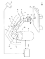
図1は、実施形態に係るロボットシステム1の構成の一例を示す図である。ロボットシステム1は、撮像部10と、ロボット20と、ロボット制御装置30を備える。
<Robot system configuration>
First, the configuration of the
FIG. 1 is a diagram illustrating an example of a configuration of a
撮像部10は、例えば、集光された光を電気信号に変換する撮像素子であるCCD(Charge Coupled Device)やCMOS(Complementary Metal Oxide Semiconductor)等を備えたカメラである。この一例において、撮像部10は、ロボット20が作業を行う作業領域RAを含む範囲を撮像可能な位置に設置される。
The
撮像部10は、ケーブルによってロボット制御装置30と通信可能に接続されている。ケーブルを介した有線通信は、例えば、イーサネット(登録商標)やUSB(Universal Serial Bus)等の規格によって行われる。なお、撮像部10は、Wi−Fi(登録商標)等の通信規格により行われる無線通信によってロボット制御装置30と接続される構成であってもよい。
The
ロボット20は、アームAと、アームAを支持する支持台Bを備える単腕ロボットである。単腕ロボットは、この一例におけるアームAのような1本のアーム(腕)を備えるロボットである。なお、ロボット20は、単腕ロボットに代えて、複腕ロボットであってもよい。複腕ロボットは、2本以上のアーム(例えば、2本以上のアームA)を備えるロボットである。なお、複腕ロボットのうち、2本のアームを備えるロボットは、双腕ロボットとも称される。すなわち、ロボット20は、2本のアームを備える双腕ロボットであってもよく、3本以上のアーム(例えば、3本以上のアームA)を備える複腕ロボットであってもよい。また、ロボット20は、スカラロボットや、直角座標ロボット等の他のロボットであってもよい。直角座標ロボットは、例えば、ガントリロボットである。
The
アームAは、エンドエフェクターEと、マニピュレーターMを備える。
エンドエフェクターEは、この一例において、物体を把持可能な指部を備えるエンドエフェクターである。なお、エンドエフェクターEは、当該指部を備えるエンドエフェクターに代えて、空気の吸引や磁力、治具等によって物体を持ち上げることが可能なエンドエフェクターや、他のエンドエフェクターであってもよい。
The arm A includes an end effector E and a manipulator M.
In this example, the end effector E is an end effector including a finger portion that can grip an object. The end effector E may be an end effector capable of lifting an object by air suction, a magnetic force, a jig or the like, or another end effector, instead of the end effector including the finger portion.
エンドエフェクターEは、ケーブルによってロボット制御装置30と通信可能に接続されている。これにより、エンドエフェクターEは、ロボット制御装置30から取得される制御信号に基づく動作を行う。なお、ケーブルを介した有線通信は、例えば、イーサネット(登録商標)やUSB等の規格によって行われる。また、エンドエフェクターEは、Wi−Fi(登録商標)等の通信規格により行われる無線通信によってロボット制御装置30と接続される構成であってもよい。
The end effector E is communicably connected to the
マニピュレーターMは、関節J1〜関節J7の7つの関節を備える。また、関節J1〜関節J7のそれぞれは、図示しないアクチュエーターを備える。すなわち、マニピュレーターMを備えるアームAは、7軸垂直多関節型のアームである。アームAは、支持台Bと、エンドエフェクターEと、マニピュレーターMと、マニピュレーターMが備える7つの関節それぞれのアクチュエーターとによる連携した動作によって7軸の自由度の動作を行う。なお、アームAは、6軸以下の自由度で動作する構成であってもよく、8軸以上の自由度で動作する構成であってもよい。 The manipulator M includes seven joints, a joint J1 to a joint J7. Each of the joints J1 to J7 includes an actuator (not shown). That is, the arm A including the manipulator M is a 7-axis vertical articulated arm. The arm A performs an operation with seven degrees of freedom by a coordinated operation by the support base B, the end effector E, the manipulator M, and the actuators of each of the seven joints included in the manipulator M. The arm A may be configured to operate with a degree of freedom of 6 axes or less, or may be configured to operate with a degree of freedom of 8 axes or more.
アームAが7軸の自由度で動作する場合、アームAは、6軸以下の自由度で動作する場合と比較して取り得る姿勢が増える。これによりアームAは、例えば、動作が滑らかになり、更にアームAの周辺に存在する物体との干渉を容易に回避することができる。また、アームAが7軸の自由度で動作する場合、アームAの制御は、アームAが8軸以上の自由度で動作する場合と比較して計算量が少なく容易である。 When the arm A operates with a degree of freedom of 7 axes, the posture that the arm A can take is increased as compared with the case where the arm A operates with a degree of freedom of 6 axes or less. Thereby, for example, the operation of the arm A is smooth, and interference with an object existing around the arm A can be easily avoided. Further, when the arm A operates with a degree of freedom of 7 axes, the control of the arm A is easy and requires a smaller amount of calculation than when the arm A operates with a degree of freedom of 8 axes or more.
この一例において、関節J1、関節J3、関節J5、関節J7のそれぞれは、回転関節である。回転関節は、回動軸の回動によって回動軸に接続された2つのリンク間の角度を変化させない関節である。リンクは、マニピュレーターMが有する部材であって関節間を繋ぐ部材である。また、関節J2、関節J4、関節J6のそれぞれは、旋回関節である。旋回関節は、回動軸の回動によって回動軸に接続された2つのリンク間の角度を変化させる関節である。 In this example, each of the joint J1, the joint J3, the joint J5, and the joint J7 is a rotary joint. The rotary joint is a joint that does not change the angle between two links connected to the rotary shaft by the rotation of the rotary shaft. The link is a member that the manipulator M has and that connects the joints. Each of the joint J2, the joint J4, and the joint J6 is a turning joint. The turning joint is a joint that changes the angle between two links connected to the turning shaft by turning the turning shaft.
マニピュレーターMが備える7つの(関節に備えられた)アクチュエーターはそれぞれ、ケーブルによってロボット制御装置30と通信可能に接続されている。これにより、当該アクチュエーターは、ロボット制御装置30から取得される制御信号に基づいて、マニピュレーターMを動作させる。また、各アクチュエーターは、エンコーダーを備えている。各エンコーダーは、各エンコーダーが備えられたアクチュエーターの回転角を示す情報をロボット制御装置30に出力する。なお、ケーブルを介した有線通信は、例えば、イーサネット(登録商標)やUSB等の規格によって行われる。また、マニピュレーターMが備える7つのアクチュエーターのうちの一部又は全部は、Wi−Fi(登録商標)等の通信規格により行われる無線通信によってロボット制御装置30と接続される構成であってもよい。
Each of the seven actuators (provided at the joints) included in the manipulator M is communicably connected to the
ロボット制御装置30は、この一例において、ロボットコントローラーである。ロボット制御装置30は、ユーザーにより予め入力された動作プログラムに基づいて、ロボット20を動作させる制御信号を生成する。ロボット制御装置30は、生成した制御信号をロボット20に出力し、ロボット20に所定の作業を行わせる。
In this example, the
<ロボットが行う所定の作業>
以下、ロボット20が行う所定の作業について説明する。図1に示した例では、作業台TBの上面に物体Oが載置されている。作業台TBは、例えば、テーブルである。なお、作業台TBは、テーブルに代えて、床面や棚等の物体Oを載置可能な物体であれば如何なる物体であってもよい。
<Predetermined work performed by the robot>
Hereinafter, predetermined work performed by the
物体Oは、例えば、産業用の部品や部材、製品等である。なお、物体Oは、これに代えて、産業用と異なる日用品の部品や部材、製品等や、生体等の他の物体であってもよい。図1に示した例では、物体Oが直方体形状の物体として表されている。なお、物体Oの形状は、直方体形状に代えて、他の形状であってもよい。物体Oが有する面のうちの作業台TBの上面と接面している面と反対側の面には、マーカーMKが設けられている。マーカーMKは、ロボット座標系RCにおける物体Oの重心の位置及び姿勢を示す印である。図1では、マーカーMKは、物体Oの当該面上における長方形状の印として示されている。なお、マーカーMKは、これに代えて、当該位置及び姿勢を示す物体Oの一部であってもよい。また、マーカーMKは、長方形状に代えて、他の形状であってもよい。 The object O is, for example, an industrial part, member, product, or the like. Instead of this, the object O may be a part or member of daily necessities different from that for industrial use, a product, or another object such as a living body. In the example shown in FIG. 1, the object O is represented as a rectangular parallelepiped object. The shape of the object O may be another shape instead of the rectangular parallelepiped shape. A marker MK is provided on the surface of the object O opposite to the surface that is in contact with the upper surface of the work table TB. The marker MK is a mark indicating the position and posture of the center of gravity of the object O in the robot coordinate system RC. In FIG. 1, the marker MK is shown as a rectangular mark on the surface of the object O. Alternatively, the marker MK may be a part of the object O indicating the position and posture. Further, the marker MK may have another shape instead of the rectangular shape.
ロボット20は、所定の作業として、エンドエフェクターEにより物体Oを把持し、把持した物体Oを図示しない所定の給材領域に配置する作業を行う。なお、所定の作業は、これに代えて、他の作業であってもよい。
The
<ロボット制御装置が行う処理の概要>
以下、ロボット制御装置30が行う処理の概要について説明する。
<Outline of processing performed by robot controller>
Hereinafter, an outline of processing performed by the
ロボット制御装置30は、エンドエフェクターEに予め対応付けられた位置に、エンドエフェクターEとともに動く制御点Tを設定する。エンドエフェクターEに予め対応付けられた位置は、例えば、エンドエフェクターEの重心の位置である。制御点Tは、例えば、TCP(Tool Center Point)である。なお、制御点Tは、TCPに代えて、マニピュレーターMの一部に対応付けられた仮想的な点等の他の仮想的な点であってもよい。すなわち、制御点Tは、エンドエフェクターEに対応付けられた位置に代えて、エンドエフェクターEの他の部位の位置に設定される構成であってもよく、マニピュレーターMに対応付けられた何らかの位置に設定される構成であってもよい。
The
制御点Tには、制御点Tの位置を示す情報である制御点位置情報と、制御点Tの姿勢を示す情報である制御点姿勢情報とが対応付けられている。なお、制御点Tには、これらに加えて、他の情報が対応付けられる構成であってもよい。制御点位置情報及び制御点姿勢情報をロボット制御装置30が指定(決定)すると、制御点Tの位置及び姿勢が決まる。当該位置及び姿勢は、ロボット座標系RCにおける位置及び姿勢である。ロボット制御装置30は、制御点位置情報及び制御点姿勢情報を指定する。ロボット制御装置30は、アームAを動作させ、ロボット制御装置30が指定した制御点位置情報が示す位置に制御点Tの位置を一致させるとともに、ロボット制御装置30が指定した制御点姿勢情報が示す姿勢に制御点Tの姿勢を一致させる。以下では、説明の便宜上、ロボット制御装置30が指定した制御点位置情報が示す位置を目標位置と称し、ロボット制御装置30が指定した制御点姿勢情報が示す姿勢を目標姿勢と称して説明する。すなわち、ロボット制御装置30は、制御点位置情報及び制御点姿勢情報を指定することにより、ロボット20を動作させ、制御点Tの位置及び姿勢を目標位置及び目標姿勢と一致させる。
The control point T is associated with control point position information, which is information indicating the position of the control point T, and control point attitude information, which is information indicating the attitude of the control point T. The control point T may be configured to be associated with other information in addition to these. When the
この一例において、制御点Tの位置は、制御点座標系TCの原点のロボット座標系RCにおける位置によって表される。また、制御点Tの姿勢は、制御点座標系TCの各座標軸のロボット座標系RCにおける方向によって表される。制御点座標系TCは、制御点Tとともに動くように制御点Tに対応付けられた三次元局所座標系である。 In this example, the position of the control point T is represented by the position of the origin of the control point coordinate system TC in the robot coordinate system RC. The attitude of the control point T is represented by the direction in the robot coordinate system RC of each coordinate axis of the control point coordinate system TC. The control point coordinate system TC is a three-dimensional local coordinate system associated with the control point T so as to move with the control point T.
ロボット制御装置30は、ユーザーから予め入力された制御点設定情報に基づいて制御点Tを設定する。制御点設定情報は、例えば、エンドエフェクターEの重心の位置及び姿勢と制御点Tの位置及び姿勢との相対的な位置及び姿勢を示す情報である。なお、制御点設定情報は、これに代えて、エンドエフェクターEに対応付けられた何らかの位置及び姿勢と制御点Tの位置及び姿勢との相対的な位置及び姿勢を示す情報であってもよく、マニピュレーターMに対応付けられた何らかの位置及び姿勢と制御点Tの位置及び姿勢との相対的な位置及び姿勢を示す情報であってもよく、ロボット20の他の部位に対応付けられた何らかの位置及び姿勢と制御点Tの位置及び姿勢との相対的な位置及び姿勢を示す情報であってもよい。
The
ロボット制御装置30は、撮像部10に作業領域RAを含む範囲を撮像させる。ロボット制御装置30は、撮像部10が撮像した撮像画像を取得する。ロボット制御装置30は、撮像部10から取得した撮像画像に基づいて、当該撮像画像に含まれる対象物の位置及び姿勢を検出する。当該位置及び姿勢は、撮像部座標系CCにおける対象物の位置及び姿勢である。対象物は、例えば、エンドエフェクターEの一部又は全部、マニピュレーターMの一部又は全部、ロボット20と別体の物体等である。以下では、一例として、当該対象物が図1に示した物体Oである場合について説明する。撮像部座標系CCは、撮像部10が撮像した撮像画像上の位置及び姿勢を表す三次元局所座標系である。
The
すなわち、ロボット制御装置30は、撮像部10から取得した撮像画像から撮像部座標系CCにおける物体Oの位置及び姿勢を検出する。物体Oの位置及び姿勢は、物体Oに対応付けられた位置及び姿勢である。以下では、一例として、物体Oの位置及び姿勢が、ユーザーにより予め入力された把持位置及び把持姿勢によって表される場合について説明する。把持位置及び把持姿勢は、物体OをエンドエフェクターEに把持させる直前においてロボット制御装置30が制御点Tの位置及び姿勢を一致させる目標の位置及び姿勢のことである。なお、物体Oの位置及び姿勢は、把持位置及び把持姿勢に代えて、物体Oに対応付けられた他の位置及び姿勢によって表される構成であってもよい。
That is, the
より具体的には、ロボット制御装置30は、撮像部10から取得した撮像画像からマーカーMKを検出する。ロボット制御装置30は、検出したマーカーMKに基づいて、撮像部座標系CCにおける物体Oの重心の位置及び姿勢を検出する。そして、ロボット制御装置30は、検出した当該位置及び姿勢と、ユーザーにより予め入力された把持位置姿勢情報とに基づいて、撮像部座標系CCにおける物体Oの位置及び姿勢を検出する。把持位置姿勢情報は、物体Oの重心の位置及び姿勢からの相対的な位置及び姿勢として前述の把持位置及び把持姿勢を示す情報である。なお、ロボット制御装置30は、例えば、パターンマッチング等によって当該撮像画像から撮像部座標系CCにおける物体Oの重心の位置及び姿勢を検出する構成であってもよい。
More specifically, the
ロボット制御装置30は、撮像部10から取得した撮像画像から検出した撮像部座標系CCにおける物体Oの位置及び姿勢に基づいて、当該位置及び姿勢を表す第1情報を算出する。ロボット制御装置30は、算出した第1情報を、物体Oの第1座標系における位置及び姿勢を表す第2情報へと変換する。ロボット制御装置30は、変換した第2情報が表わす位置を示す情報を制御点位置情報として指定し、変換した第2情報が表わす姿勢を示す情報を制御点姿勢情報として指定する。ロボット制御装置30は、指定した制御点位置情報及び制御点姿勢情報に基づいて、第1座標系における制御点Tの位置及び姿勢が、第1座標系における目標位置及び目標姿勢に変化するように、マニピュレーターMの各関節を回転させる制御信号を生成する。ロボット制御装置30は、生成した制御信号をロボット20に出力し、第1座標系における制御点Tの位置及び姿勢を、第1座標系における目標位置及び目標姿勢である把持位置及び把持姿勢に一致させる。そして、ロボット制御装置30は、物体OをエンドエフェクターEに把持させる。ロボット制御装置30は、ユーザーにより予め入力された給材領域の位置を示す情報に基づいて、エンドエフェクターEにより把持された物体Oを図示しない給材領域に配置する。このように、ロボット制御装置30は、ロボット20に所定の作業を行わせる。
Based on the position and orientation of the object O in the imaging unit coordinate system CC detected from the captured image acquired from the
以下では、一例として、第1情報が第1行列CTTCPである場合について説明する。この場合、第2情報は、第2行列RTTCPである。なお、第1情報は、第1行列CTTCPに代えて、第1行列CTTCPが有する各成分を表す情報を含むデータベースや、当該情報を表す複数の方程式を示す情報等の他の情報であってもよい。この場合、第2情報は、第1情報に応じた情報である。また、以下では、一例として、第1座標系がロボット座標系RCである場合について説明する。なお、第1座標系は、ロボット座標系RCに代えて、ワールド座標系等の他の座標系であってもよい。 Hereinafter, as an example, a case where the first information is the first matrix C T TCP will be described. In this case, the second information is the second matrix R T TCP . The first information, instead of the first matrix C T TCP, or database that contains information representing each component included in the first matrix C T TCP, other information such as information indicating a plurality of equations representing the information It may be. In this case, the second information is information corresponding to the first information. In the following, a case where the first coordinate system is the robot coordinate system RC will be described as an example. The first coordinate system may be another coordinate system such as a world coordinate system instead of the robot coordinate system RC.
すなわち、ロボット制御装置30は、撮像部10から取得した撮像画像から検出した撮像部座標系CCにおける物体Oの位置及び姿勢に基づいて、当該位置及び姿勢を表す第1行列CTTCPを算出する。ロボット制御装置30は、算出した第1行列CTTCPを、物体Oのロボット座標系RCにおける位置及び姿勢を表す第2行列RTTCPへと変換する。ロボット制御装置30は、変換した第2行列RTTCPが表わす位置を示す情報を制御点位置情報として指定し、変換した第2行列RTTCPが表わす姿勢を示す情報を制御点姿勢情報として指定する。ロボット制御装置30は、指定した制御点位置情報及び制御点姿勢情報に基づいて、ロボット座標系RCにおける制御点Tの位置及び姿勢が、ロボット座標系RCにおける目標位置及び目標姿勢に変化するように、マニピュレーターMの各関節を回転させる制御信号を生成する。ロボット制御装置30は、生成した制御信号をロボット20に出力し、ロボット座標系RCにおける制御点Tの位置及び姿勢を、ロボット座標系RCにおける目標位置及び目標姿勢である把持位置及び把持姿勢に一致させる。そして、ロボット制御装置30は、物体OをエンドエフェクターEに把持させる。ロボット制御装置30は、ユーザーにより予め入力された給材領域の位置を示す情報に基づいて、エンドエフェクターEにより把持された物体Oを図示しない給材領域に配置する。このように、ロボット制御装置30は、ロボット20に所定の作業を行わせる。
That is, the
ロボット制御装置30が第1行列CTTCPを第2行列RTTCPに変換する際、ロボット制御装置30には、第1行列CTTCPを第2行列RTTCPに変換する変換情報が予め記憶されている。ロボット制御装置30は、複数の変換情報の中から1つの変換情報を対象変換情報として選択し、選択した対象変換情報に基づいて第1行列CTTCPを第2行列RTTCPに変換する。これにより、ロボット制御装置30は、所定の作業をロボット20に行わせる。
When the
以下では、一例として、変換情報が変換行列RTCである場合について説明する。なお、変換情報は、これに代えて、変換行列RTCが有する各成分を表す情報を含むデータベースや、当該情報を表す複数の方程式を示す情報等の他の情報であってもよい。 Hereinafter, as an example, a case where the conversion information is a conversion matrix R T C will be described. Instead of this, the conversion information may be other information such as a database including information indicating each component included in the conversion matrix R T C or information indicating a plurality of equations indicating the information.
すなわち、ロボット制御装置30が第1行列CTTCPを第2行列RTTCPに変換する際、ロボット制御装置30には、第1行列CTTCPを第2行列RTTCPに変換する変換行列RTCが予め記憶されている。ロボット制御装置30は、複数の変換行列RTCの中から1つの変換行列RTCを対象変換行列RTCとして選択し、選択した対象変換行列RTCに基づいて第1行列CTTCPを第2行列RTTCPに変換する。これにより、ロボット制御装置30は、所定の作業をロボット20に行わせる。以下では、ロボット制御装置30が複数の変換行列RTCの中から1つの変換行列RTCを対象変換行列RTCとして選択する処理について詳しく説明する。また、以下では、ロボット制御装置30が複数の変換行列RTCを生成する処理について詳しく説明する。
That is, when the
ここで、変換行列RTCと、第1行列CTTCP及び第2行列RTTCPとの関係は、以下に示した式(1)、式(2)によって表される。 Here, the relationship between the transformation matrix R T C , the first matrix C T TCP, and the second matrix R T TCP is expressed by the following equations (1) and (2).

上記の式(2)は、第1行列CTTCPの逆行列を表している。なお、以下では、説明の便宜上、第1行列CTTCPを単に第1行列と称し、第2行列RTTCPを単に第2行列と称し、変換行列RTCを単に変換行列と称して説明する。 The above equation (2) represents the inverse matrix of the first matrix C T TCP . Hereinafter, for convenience of explanation, the first matrix C T TCP is simply referred to as a first matrix, the second matrix R T TCP is simply referred to as a second matrix, and the transformation matrix R T C is simply referred to as a transformation matrix. To do.
<ロボット制御装置のハードウェア構成>
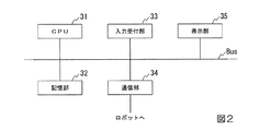
以下、図2を参照し、ロボット制御装置30のハードウェア構成について説明する。図2は、ロボット制御装置30のハードウェア構成の一例を示す図である。
<Hardware configuration of robot controller>
Hereinafter, the hardware configuration of the
ロボット制御装置30は、例えば、CPU(Central Processing Unit)31と、記憶部32と、入力受付部33と、通信部34と、表示部35を備える。また、ロボット制御装置30は、通信部34を介してロボット20と通信を行う。これらの構成要素は、バスBusを介して相互に通信可能に接続されている。
The
CPU31は、記憶部32に格納された各種プログラムを実行する。
記憶部32は、例えば、HDD(Hard Disk Drive)やSSD(Solid State Drive)、EEPROM(Electrically Erasable Programmable Read−Only Memory)、ROM(Read−Only Memory)、RAM(Random Access Memory)等を含む。なお、記憶部32は、ロボット制御装置30に内蔵されるものに代えて、USB等のデジタル入出力ポート等によって接続された外付け型の記憶装置であってもよい。記憶部32は、ロボット制御装置30が処理する各種情報や画像、動作プログラムを含む各種のプログラム、前述の把持位置姿勢情報、変換行列テーブル等を格納する。変換行列テーブルは、前述の複数の変換行列のそれぞれが格納されたテーブルである。
The
The
入力受付部33は、例えば、表示部35と一体に構成されたタッチパネルである。なお、入力受付部33は、キーボードやマウス、タッチパッド、その他の入力装置であってもよい。
通信部34は、例えば、USB等のデジタル入出力ポートやイーサネット(登録商標)ポート等を含んで構成される。
表示部35は、例えば、液晶ディスプレイパネル、あるいは、有機EL(ElectroLuminescence)ディスプレイパネルである。
The
The
The
<ロボット制御装置の機能構成>
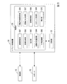
以下、図3を参照し、ロボット制御装置30の機能構成について説明する。図3は、ロボット制御装置30の機能構成の一例を示す図である。
<Functional configuration of robot controller>
Hereinafter, the functional configuration of the
ロボット制御装置30は、記憶部32と、制御部36を備える。
The
制御部36は、ロボット制御装置30の全体を制御する。制御部36は、撮像制御部361と、画像取得部362と、算出部363と、変換行列選択部364と、行列変換部365と、回転角情報取得部366と、変換行列生成部367と、記憶制御部368と、ロボット制御部369と、検出部370を備える。制御部36が備えるこれらの機能部は、例えば、CPU31が、記憶部32に記憶された各種プログラムを実行することにより実現される。また、当該機能部のうちの一部又は全部は、LSI(Large Scale Integration)やASIC(Application Specific Integrated Circuit)等のハードウェア機能部であってもよい。
The
撮像制御部361は、撮像部10に作業領域RAを含む範囲を撮像させる。
画像取得部362は、撮像部10が撮像した撮像画像を撮像部10から取得する。
算出部363は、画像取得部362が取得した撮像画像から検出部370が検出した物体Oの位置及び姿勢を表す第1行列を算出する。当該位置及び姿勢は、撮像部座標系CCにおける位置及び姿勢である。また、算出部363は、検出部370が検出した制御点Tの位置及び姿勢を表す第1行列を算出する。当該位置及び姿勢は、撮像部座標系CCにおける位置及び姿勢である。また、算出部363は、回転角情報取得部366が取得した回転角情報と、順運動学とに基づいて、制御点Tの位置及び姿勢を算出する。算出部363は、算出した当該位置及び姿勢を表す第2行列を算出する。当該位置及び姿勢は、ロボット座標系RCにおける位置及び姿勢である。
The
The
The
変換行列選択部364は、記憶部32に記憶された変換行列テーブルを読み出す。変換行列選択部364は、読み出した変換行列テーブルに格納された複数の変換行列から所定の条件を満たす変換行列を対象変換行列として選択する。
行列変換部365は、変換行列選択部364が選択した対象変換行列に基づいて、算出部363が算出した第1行列を第2行列に変換する。
The conversion
The
回転角情報取得部366は、マニピュレーターMの各関節が備えるアクチュエーターの回転角を示す回転角情報を、当該アクチュエーターのそれぞれが備えるエンコーダーから取得する。
変換行列生成部367は、算出部363が算出した第1行列及び第2行列に基づいて、変換行列を生成する。当該第1行列は、撮像部座標系CCにおける制御点Tの位置及び姿勢を表す第1行列である。当該第2行列は、ロボット座標系RCにおける制御点Tの位置及び姿勢を表す第2行列である。
The rotation angle information acquisition unit 366 acquires rotation angle information indicating the rotation angle of the actuator included in each joint of the manipulator M from the encoder included in each of the actuators.
The transformation
記憶制御部368は、変換行列テーブルを記憶部32の記憶領域内に生成する。記憶制御部368は、当該記憶領域内に生成した変換行列テーブルに、変換行列生成部367が生成した変換行列を格納する。
ロボット制御部369は、行列変換部365が変換した第2行列が表わす位置及び姿勢に基づいてロボット20を動作させ、ロボット20に所定の作業を行わせる。
検出部370は、画像取得部362が取得した撮像画像から撮像部座標系CCにおける物体Oの位置及び姿勢を検出する。また、検出部370は、画像取得部362が取得した撮像画像から撮像部座標系CCにおける制御点Tの位置及び姿勢を検出する。
The
The
The
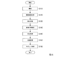
<ロボット制御装置が変換行列を選択する処理>
以下、図4を参照し、ロボット制御装置30が複数の変換行列の中から所定の条件を満たす変換行列を対象変換行列として選択する処理について説明する。図4は、ロボット制御装置30が複数の変換行列の中から所定の条件を満たす変換行列を対象変換行列として選択する処理の流れの一例を示すフローチャートである。なお、図4に示したフローチャートの処理では、複数の変換行列を格納した変換行列テーブルが予め記憶部32に記憶されている場合について説明する。
<Process where robot controller selects transformation matrix>
Hereinafter, a process in which the
撮像制御部361は、撮像部10に作業領域RAを含む範囲を撮像させる(ステップS110)。次に、画像取得部362は、ステップS110において撮像部10が撮像した撮像画像を撮像部10から取得する(ステップS120)。
The
次に、検出部370は、ステップS120において画像取得部362が取得した撮像画像に含まれる物体Oの位置及び姿勢を検出する検出処理を実行する(ステップS130)。当該位置及び姿勢は、撮像部座標系CCにおける位置及び姿勢である。例えば、検出部370は、当該物体Oに設けられたマーカーMKを検出する。検出部370は、検出したマーカーMKが示す位置及び姿勢を検出する。当該位置及び姿勢は、撮像部座標系CCにおける物体Oの重心の位置及び姿勢である。検出部370は、記憶部32に予め記憶された把持位置姿勢情報を読み出す。検出部370は、読み出した把持位置姿勢情報と、検出したマーカーMKが示す位置及び姿勢とに基づいて、物体Oの位置及び姿勢を検出する。
Next, the
なお、検出部370は、マーカーMKによって撮像部座標系CCにおける物体Oの重心の位置及び姿勢を検出する構成に代えて、パターンマッチング等の他の手法によって当該撮像画像から当該位置及び姿勢を検出する構成であってもよい。パターンマッチングによって当該位置及び姿勢を検出する場合、検出部370は、記憶部32に予め記憶された物体Oのリファレンスモデルに基づくパターンマッチングによって当該撮像画像から当該位置及び姿勢を検出する。物体Oのリファレンスモデルは、物体Oの三次元形状、色彩、模様等を三次元モデル化して得られた三次元モデルデータであり、例えば、CG(Computer Graphics)によって表される。
Note that the
次に、変換行列選択部364は、記憶部32に予め記憶された変換行列テーブルの中から所定の条件を満たす変換行列を対象変換行列として選択する(ステップS140)。ここで、ステップS140の処理について説明する。変換行列選択部364は、記憶部32に予め記憶された冗長回転角情報と、ポーズ情報とを読み出す。
Next, the transformation
冗長回転角情報は、冗長回転角(冗長自由度)を示す情報である。冗長回転角は、この一例において、基準平面に対する対象平面の角度のことである。対象平面は、ある位置及び姿勢である位置姿勢XXと制御点Tの位置及び姿勢とが一致している場合において、マニピュレーターMが備える関節のうちの関節J2と、関節J4と、関節J6とのそれぞれを直線により結ぶことによって形成される三角形を含む平面である。より具体的には、例えば、対象平面は、アームAが備える関節のうちの関節J2の重心の位置と、関節J4の重心の位置と、関節J6の重心の位置とのそれぞれを直線により結ぶことによって形成される三角形を含む平面である。なお、対象平面は、これに代えて、関節J2の他の位置と、関節J4の他の位置と、関節J6の他の位置とのそれぞれを直線により結ぶことによって形成される三角形を含む平面であってもよい。基準平面は、関節J1、関節J2、関節J4、関節J5、関節J6、関節J7の6つの関節を備えるアームの制御点の位置及び姿勢が前述の位置姿勢XXと一致している場合において、当該アームが備える関節のうちの関節J2、関節J4、関節J6のそれぞれを直線によって結ぶことによって形成される三角形を含む平面のことである。より具体的には、例えば、基準平面は、当該アームが備える関節のうちの関節J2の重心の位置と、関節J4の重心の位置と、関節J6の重心の位置とのそれぞれを直線により結ぶことによって形成される三角形を含む平面である。なお、基準平面は、これに代えて、当該アームが備える関節のうちの関節J2の他の位置と、関節J4の他の位置と、関節J6の他の位置とのそれぞれを直線により結ぶことによって形成される三角形を含む平面であってもよい。 The redundant rotation angle information is information indicating a redundant rotation angle (redundancy degree of freedom). In this example, the redundant rotation angle is an angle of the target plane with respect to the reference plane. When the position and orientation XX, which is a certain position and orientation, and the position and orientation of the control point T coincide with each other, the target plane includes the joints J2, J4, and J6 of the joints included in the manipulator M. It is a plane including a triangle formed by connecting each with a straight line. More specifically, for example, the target plane connects the position of the center of gravity of the joint J2 among the joints included in the arm A, the position of the center of gravity of the joint J4, and the position of the center of gravity of the joint J6 by straight lines. Is a plane including a triangle formed by The target plane is a plane including a triangle formed by connecting each of the other position of the joint J2, the other position of the joint J4, and the other position of the joint J6 with a straight line instead. There may be. When the position and posture of the control point of the arm including the six joints of the joint J1, the joint J2, the joint J4, the joint J5, the joint J6, and the joint J7 coincide with the above-described position and posture XX, It is a plane including a triangle formed by connecting each of the joints J2, J4, and J6 of the joints included in the arm by straight lines. More specifically, for example, the reference plane connects the position of the center of gravity of the joint J2 of the joints included in the arm, the position of the center of gravity of the joint J4, and the position of the center of gravity of the joint J6 by straight lines. Is a plane including a triangle formed by Instead of this, the reference plane is formed by connecting each of the other positions of the joint J2 of the joints included in the arm, the other positions of the joint J4, and the other positions of the joint J6 by straight lines. It may be a plane including a triangle to be formed.
マニピュレーターMは、関節J1〜関節J7の7つの関節を備えているため、位置姿勢XXと制御点Tの位置及び姿勢とが一致している場合において制御点Tの位置及び姿勢を変化させずに、対象平面の基準平面に対する角度を変化させることができる。 Since the manipulator M includes seven joints J1 to J7, the position and posture of the control point T are not changed when the position and posture XX coincides with the position and posture of the control point T. The angle of the target plane relative to the reference plane can be changed.
ポーズ情報は、マニピュレーターMの関節のうちのフリップ可能関節の回転角を、互いに180°異なる2つの回転角のうちの小さい方の回転角と大きい方の回転角とのいずれにするかを指定する情報である。フリップ可能関節は、マニピュレーターMの各関節のうちの回転角が互いに180°異なる2つの回転角のいずれであっても制御点Tの位置及び姿勢を第1位置及び第1姿勢と一致させることが可能な関節である。第1位置は、ユーザーが所望する位置である。当該位置は、ロボット座標系RCにおける位置である。第1姿勢は、ユーザーが所望する姿勢である。当該姿勢は、ロボット座標系RCにおける姿勢である。この一例において、フリップ可能関節は、関節J2、関節J4、関節J6の3つの関節のそれぞれである。 The pose information specifies whether the rotation angle of the flippable joint among the joints of the manipulator M is one of the smaller rotation angle and the larger rotation angle of two rotation angles different from each other by 180 °. Information. The flippable joint can cause the position and posture of the control point T to coincide with the first position and the first posture regardless of two rotation angles of the joints of the manipulator M that are 180 ° different from each other. It is a possible joint. The first position is a position desired by the user. The position is a position in the robot coordinate system RC. The first posture is a posture desired by the user. The posture is a posture in the robot coordinate system RC. In this example, the flippable joints are each of the three joints: joint J2, joint J4, and joint J6.
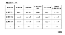
また、変換行列選択部364は、記憶部32に予め記憶された変換行列テーブルを記憶部32から読み出す。ここで、図5を参照し、変換行列テーブルについて説明する。図5は、変換行列テーブルの一例を示す図である。図5に示したように、変換行列テーブルには、複数の変換行列が、位置を示す位置情報と、姿勢を示す姿勢情報と、冗長回転角情報と、ポーズ情報とに対応付けられて格納されている。変換行列テーブル内において、複数の変換行列のそれぞれは、変換行列に対応付けられた位置情報が示す位置と、姿勢情報が示す姿勢と、冗長回転角情報が示す冗長回転角と、ポーズ情報との少なくとも1つが互いに異なる。なお、変換行列テーブルには、位置情報と、姿勢情報と、冗長回転角情報と、ポーズ情報との一部が対応付けられた変換行列が格納されている構成であってもよく、位置情報と、姿勢情報と、冗長回転角情報と、ポーズ情報との一部又は全部に代えて、他の情報が対応付けられた変換行列が格納されている構成であってもよい。
In addition, the conversion
変換行列選択部364は、記憶部32から読み出した変換行列テーブルの中から所定の条件を満たす1つの変換行列を対象変換行列として選択する。所定の条件は、この一例において、以下に示す1)〜4)の4つの条件のすべてを満たすことである。なお、所定の条件は、当該4つの条件のうちの一部の条件を満たす構成であってもよく、当該4つの条件の一部又は全部に代えて、他の条件を満たす構成であってもよい。
The transformation
1)ステップS130において検出部370が検出した物体Oの位置に最も近い位置を示す位置情報が対応付けられた変換行列であること。当該位置は、撮像部座標系CCにおける位置である。
2)ステップS130において検出部370が検出した物体Oの姿勢に最も近い姿勢を示す姿勢情報が対応付けられた変換行列であること。当該姿勢は、撮像部座標系CCにおける姿勢である。
3)記憶部32に予め記憶された冗長回転角情報、すなわちユーザーから予め入力された冗長回転角情報が示す冗長回転角に最も近い冗長回転角を示す冗長回転角情報が対応付けられた変換行列であること。
4)記憶部32に予め記憶されたポーズ情報、すなわちユーザーから予め入力されたポーズ情報と一致するポーズ情報が対応付けられた変換行列であること。
1) A transformation matrix in which position information indicating a position closest to the position of the object O detected by the
2) A transformation matrix in which posture information indicating a posture closest to the posture of the object O detected by the
3) A transformation matrix in which redundant rotation angle information stored in advance in the
4) A transformation matrix in which pose information stored in advance in the
変換行列選択部364は、ステップS130において検出部370が検出した物体Oの位置であって撮像部座標系CCにおける位置と、各変換行列に対応付けられた位置情報が示す位置との距離を算出する。変換行列選択部364は、当該位置情報の中から、算出した当該距離が最も短くなる位置を示す位置情報を特定する。変換行列選択部364は、特定した位置情報に対応付けられた変換行列を、上記の1)の条件を満たす変換行列として特定する。
The transformation
また、変換行列選択部364は、ステップS130において検出部370が検出した物体Oの姿勢であって撮像部座標系CCにおける姿勢と、各変換行列に対応付けられた姿勢情報が示す姿勢とのずれを算出する。変換行列選択部364は、当該姿勢情報の中から、算出した当該ずれが最も小さくなる姿勢を示す姿勢情報を特定する。当該ずれは、例えば、変換行列に対応付けられた姿勢情報が示す姿勢と、ステップS130において検出部370が検出した物体Oの姿勢であって撮像部座標系CCにおける姿勢との差分を表す3つのオイラー角を成分として有するベクトルのノルムによって表される。なお、当該ずれは、これに代えて、他の量によって表される構成であってもよい。変換行列選択部364は、特定した姿勢情報に対応付けられた変換行列を、上記の2)の条件を満たす変換行列として特定する。
Further, the transformation
また、変換行列選択部364は、記憶部32に予め記憶された冗長回転角情報が示す冗長回転角と、各変換行列に対応付けられた冗長回転角情報が示す冗長回転角との差分を算出する。変換行列選択部364は、当該冗長回転角情報の中から、算出した当該差分が最も小さくなる冗長回転角を示す冗長回転角情報を特定する。変換行列選択部364は、特定した冗長回転角情報に対応付けられた変換行列を、上記の3)の条件を満たす変換行列として特定する。
The transformation
また、変換行列選択部364は、記憶部32に予め記憶されたポーズ情報と一致するポーズ情報が対応付けられた変換行列を、上記の4)の条件を満たす変換行列として特定する。
このようにして、変換行列選択部364は、ステップS140において、変換行列テーブルに格納された複数の変換行列の中から所定の条件を満たす1つの変換行列を対象変換行列として選択する。
In addition, the transformation
In this way, in step S140, the transformation
次に、算出部363は、ステップS130において検出部370が検出した物体Oの位置及び姿勢を表す第1行列を算出する算出処理を実行する(ステップS145)。当該位置及び姿勢は、撮像部座標系CCにおける位置及び姿勢である。次に、行列変換部365は、ステップS140において変換行列選択部364が選択した対象変換行列に基づいて、ステップS145において算出部363が算出した第1行列を第2行列に変換する変換処理を実行する(ステップS150)。具体的には、行列変換部365は、以下に示した式(3)のように、当該対象変換行列を当該第1行列に乗算した結果として当該第1行列を第2行列に変換する。
Next, the
次に、ロボット制御部369は、ステップS150において変換した第2行列が表わす位置を示す情報を制御点位置情報として指定し、当該第2行列が表わす姿勢を示す情報を制御点姿勢情報として指定する。当該位置は、ロボット座標系RCにおける物体Oの位置である。当該姿勢は、ロボット座標系RCにおける物体Oの姿勢である。そして、ロボット制御部369は、制御点Tの位置及び姿勢を、制御点位置情報が示す位置及び制御点姿勢情報が示す姿勢に一致させる。
Next, the
この際、ロボット制御部369は、冗長回転角が、冗長回転角が記憶部32に予め記憶された冗長回転角情報が示す冗長回転角と一致する場合の関節J1〜関節J7それぞれの回転角を算出する。具体的には、ロボット制御部369は、当該回転角を算出するため、制御点位置情報が示す位置及び制御点姿勢情報が示す姿勢と、記憶部32に予め記憶された第1構造情報とに基づいて、前述の基準平面を算出する。当該基準平面は、制御点Tの位置及び姿勢と制御点位置情報が示す位置及び制御点姿勢情報が示す姿勢とが一致している場合における基準平面である。第1構造情報は、関節J3がない場合の仮想的なアームAが備える各部材の大きさや形状等の当該アームAの構造を示す情報である。ロボット制御部369は、対象平面の当該基準面に対する角度、すなわち冗長回転角が記憶部32に予め記憶された冗長回転角情報が示す冗長回転角と一致する場合の関節J1〜関節J7それぞれの回転角を算出する。この際、ロボット制御部369は、制御点位置情報が示す位置及び制御点姿勢情報が示す姿勢と、算出した基準平面と、記憶部32に予め記憶された第2構造情報とに基づいて当該回転角を算出する。この際、ロボット制御部369は、関節J2、関節J4、関節J6それぞれの回転角を、ポーズ情報が指定する回転角と一致させる。第2構造情報は、アームAが備える各部材の大きさや形状等の当該アームAの構造を示す情報である。ロボット制御部369は、算出した当該回転角と、関節J1〜関節J7それぞれの回転角とを一致させることによって制御点Tを移動させる。そして、ロボット制御部369は、エンドエフェクターEに物体Oを把持させる。ロボット制御部369は、エンドエフェクターEにより把持された物体Oを、記憶部32に予め記憶された給材領域の位置を示す情報に基づいて、図示しない給材領域に配置し(ステップS160)、処理を終了する。
At this time, the
このように、ロボット制御装置30は、撮像部10により撮像された撮像画像上の位置及び姿勢を表す撮像部座標系CCにおける物体Oの位置及び姿勢を表す第1行列を、ロボット座標系RCにおける物体Oの位置及び姿勢を表す第2行列に変換する変換行列が複数あり、複数の変換行列の中から1つの変換行列を対象変換行列として選択し、選択した当該変換行列に基づいて所定の作業をロボット20に行わせる。これにより、ロボット制御装置30は、ロボット20が行う作業の精度を向上させることができる。また、ロボット制御装置30は、所定の条件を満たす対象変換行列に基づいて当該第1行列を当該第2行列に変換するため、撮像部10により撮像された撮像画像から検出された物体OをエンドエフェクターEにより把持する際、エンドエフェクターEと物体Oとの相対的な位置関係をユーザーが所望する位置関係に精度よく一致させることができる。その結果、ロボット制御装置30は、エンドエフェクターEによって物体Oを持ち直させる動作等を行わせる必要が少なくなり、ロボット20が作業を行うために要する時間を短縮することができる。
As described above, the
また、ロボット制御装置30は、所定の条件を満たす対象変換行列に基づいて当該第1行列を当該第2行列に変換するため、エンドエフェクターEにより物体Oを把持させる際の作業領域RA内の環境に応じてマニピュレーターMの状態を変化させた場合に生じる誤差を抑制することができる。当該環境は、物体Oの位置及び姿勢や、物体Oの周囲に配置された他の物体、物体Oと壁面との位置関係等によって表される環境のことである。また、当該状態は、マニピュレーターMの各関節の回転角によって表される状態のことである。当該誤差は、ロボット20を構成する各部材の剛性等によって生じる誤差であって制御点Tの位置及び姿勢についての誤差である。当該誤差は、ポーズ情報、冗長回転角、制御点Tの姿勢のうちの少なくとも1つを変える毎に生じる。ロボット制御装置30は、所定の条件を満たす変換行列に基づいてロボット20に所定の作業を行わせることにより、当該誤差を抑制することができる。
In addition, the
<ロボット制御装置が変換行列を生成する処理>
以下、図6及び図7を参照し、ロボット制御装置30が変換行列を生成する処理について説明する。図6は、ロボット制御装置30が変換行列を生成する処理の流れの一例を示すフローチャートである。なお、図6に示したフローチャートの処理では、作業領域RAを示す領域情報が予め記憶部32に記憶されている場合について説明する。また、以下では、作業領域RAが直方体形状の領域である場合について説明する。なお、作業領域RAの形状は、直方体形状に代えて、他の形状であってもよい。
<Process in which the robot controller generates a transformation matrix>
Hereinafter, with reference to FIG. 6 and FIG. 7, a process in which the
変換行列生成部367は、記憶部32に予め記憶された領域情報を記憶部32から読み出す。変換行列生成部367は、記憶部32から読み出した領域情報が示す作業領域RAを、複数の分割領域に分割する(ステップS210)。例えば、変換行列生成部367は、直方体形状の作業領域RAを、互いに体積が同じ立方体形状の分割領域がロボット座標系RCにおける各座標軸方向に隙間なく並ぶように分割する。なお、分割領域の形状は、立方体形状に代えて、他の形状であってもよい。また、複数の分割領域の一部又は全部の体積は、互いに異なる体積であってもよい。また、複数の分割領域の一部又は全部の形状は、互いに異なる形状であってもよい。
The transformation
次に、変換行列生成部367は、ステップS210において作業領域RAを分割した分割領域に応じた複数の測定点を生成する(ステップS220)。測定点は、制御点Tを一致させる仮想的な点のことである。測定点には、測定点の位置を示す測定点位置情報と、測定点の姿勢を示す測定点姿勢情報とが対応付けられている。この一例において、測定点と制御点Tとが一致することは、測定点の位置及び姿勢と、制御点Tの位置及び姿勢とが一致することを意味する。以下では、一例として、すべての測定点の姿勢が同じ姿勢である場合について説明する。なお、測定点の一部又は全部の姿勢は、これに代えて、互いに異なる姿勢であってもよい。
Next, the transformation
ここで、図7を参照し、複数の分割領域に分割された作業領域RAと測定点とについて説明する。図7は、複数の分割領域に分割された作業領域RAと測定点とを例示する図である。図7に示した例では、作業領域RAは、点線で区切られた8つの分割領域に分割されている。これらの分割領域は、前述したように、互いに体積が同じ立方体形状の分割領域である。 Here, with reference to FIG. 7, the work area RA and the measurement points divided into a plurality of divided areas will be described. FIG. 7 is a diagram illustrating a work area RA and measurement points divided into a plurality of divided areas. In the example shown in FIG. 7, the work area RA is divided into eight divided areas divided by dotted lines. As described above, these divided areas are cubic-shaped divided areas having the same volume.
変換行列生成部367は、例えば、作業領域RAを8つの分割領域に区切る線(図7に示した例では、点線)同士が交わる位置を特定する。変換行列生成部367は、分割領域に応じた測定点として、特定した位置に仮想的な点を生成する。変換行列生成部367は、生成した測定点毎に、測定点の位置を示す測定点位置情報と測定点の姿勢を示す測定点姿勢情報とを測定点に対応付ける。複数の測定点それぞれの姿勢は、如何なる姿勢であってもよい。また、複数の測定点の一部又は全部の姿勢は、互いに異なる姿勢であってもよく、互いに同じ姿勢であってもよい。図7に示した例では、当該点線同士が交わる位置に示した丸印が各測定点を示している。
For example, the transformation
ステップS220において生成した複数の測定点を生成した後、回転角情報取得部366と、変換行列生成部367と、記憶制御部368と、ロボット制御部369と、検出部370とのそれぞれは、生成した複数の測定点毎に、ステップS240〜ステップS340の処理を繰り返し行う(ステップS230)。
After generating the plurality of measurement points generated in step S220, each of the rotation angle information acquisition unit 366, the transformation
ロボット制御部369は、制御点Tを移動させ、ステップS230において選択された測定点に制御点Tを一致させる(ステップS240)。そして、回転角情報取得部366と、変換行列生成部367と、記憶制御部368と、ロボット制御部369と、検出部370とのそれぞれは、変換行列を生成する処理として、ステップS250〜ステップS340の処理を実行する。
The
ステップS220において選択された測定点に制御点Tが一致した後、ロボット制御部369は、記憶部32に予め記憶された複数の試験姿勢を示す試験姿勢情報を記憶部32から読み出す。そして、ロボット制御部369は、読み出した試験姿勢情報が示す複数の試験姿勢毎に、ステップS260〜ステップS340の処理を繰り返し行う(ステップS250)。
After the control point T matches the measurement point selected in step S220, the
複数の試験姿勢には、例えば、制御点Tの姿勢を基準となる姿勢から、0°〜360°の範囲において制御点座標系TCにおけるX軸周りに第1所定角度ずつ回転させた姿勢のそれぞれと、0°〜360°の範囲において制御点Tの姿勢を基準となる姿勢から制御点座標系TCにおけるY軸周りに第2所定角度ずつ回転させた姿勢のそれぞれと、0°〜360°の範囲において制御点Tの姿勢を基準となる姿勢から制御点座標系TCにおけるZ軸周りに第3所定角度ずつ回転させた姿勢のそれぞれとが含まれる。制御点Tの姿勢のうちの基準となる姿勢は、例えば、制御点座標系TCの各座標軸がロボット座標系RCの各座標軸と一致する姿勢である。 The plurality of test postures include, for example, postures rotated by a first predetermined angle around the X axis in the control point coordinate system TC in the range of 0 ° to 360 ° from a posture based on the posture of the control point T. And an attitude rotated by a second predetermined angle around the Y axis in the control point coordinate system TC from an attitude based on the attitude of the control point T in the range of 0 ° to 360 °, and 0 ° to 360 °. In the range, each of the postures rotated by a third predetermined angle around the Z axis in the control point coordinate system TC from the posture based on the posture of the control point T is included. The reference posture among the postures of the control point T is, for example, a posture in which each coordinate axis of the control point coordinate system TC coincides with each coordinate axis of the robot coordinate system RC.
第1所定角度は、例えば、30°である。なお、第1所定角度は、30°に代えて、360°を等分割することができる角度であれば30°より小さな角度であってもよく、30°より大きな角度であってもよい。第2所定角度は、例えば、30°である。また、第2所定角度は、30°に代えて、360°を等分割することができる角度であれば30°より小さな角度であってもよく、30°より大きな角度であってもよい。第3所定角度は、例えば、30°である。また、第3所定角度は、30°に代えて、360°を等分割することができる角度であれば30°より小さな角度であってもよく、30°より大きな角度であってもよい。 The first predetermined angle is 30 °, for example. The first predetermined angle may be an angle smaller than 30 ° or an angle larger than 30 ° as long as 360 ° can be equally divided instead of 30 °. The second predetermined angle is, for example, 30 °. Further, the second predetermined angle may be an angle smaller than 30 ° or an angle larger than 30 ° as long as 360 ° can be equally divided instead of 30 °. The third predetermined angle is 30 °, for example. Further, the third predetermined angle may be an angle smaller than 30 ° or an angle larger than 30 ° as long as 360 ° can be equally divided instead of 30 °.
なお、制御点Tの姿勢のうちの基準となる姿勢は、これに代えて、他の姿勢であってもよい。また、複数の試験姿勢には、これらの姿勢に代えて、他の姿勢が含まれる構成であってもよい。当該他の姿勢は、例えば、0°〜360°の範囲において制御点座標系TCにおけるX軸周り、Y軸周りの順に第4所定角度ずつ回転させた姿勢のそれぞれ等である。この場合、第4所定角度は、例えば、30°である。第4所定角度は、30°に代えて、360°を等分割することができる角度であれば30°より小さな角度であってもよく、30°より大きな角度であってもよい。 Note that the reference posture among the postures of the control point T may be another posture instead of this. The plurality of test postures may include other postures instead of these postures. The other postures are, for example, postures rotated by a fourth predetermined angle in the order around the X axis and the Y axis in the control point coordinate system TC in the range of 0 ° to 360 °, for example. In this case, the fourth predetermined angle is 30 °, for example. The fourth predetermined angle may be an angle smaller than 30 ° or an angle larger than 30 ° as long as 360 ° can be equally divided instead of 30 °.
ステップS250において試験姿勢を選択した後、ロボット制御部369は、記憶部32に予め記憶された複数の試験冗長回転角を示す試験冗長回転角情報を記憶部32から読み出す。そして、ロボット制御部369は、読み出した試験冗長回転角情報が示す複数の試験冗長回転角毎に、ステップS270〜ステップS340の処理を繰り返し行う(ステップS260)。
After selecting the test posture in step S250, the
複数の試験冗長回転角には、例えば、冗長回転角を基準となる冗長回転角から、0°〜360°の範囲において第5所定角度ずつ回転させた冗長回転角のそれぞれが含まれる。冗長回転角のうちの基準となる冗長回転角は、例えば、0°である。なお、当該基準となる冗長回転角は、これに代えて、他の冗長回転角であってもよい。第5所定角度は、例えば、20°である。なお、第5所定角度は、20°に代えて、360°を等分割することができる角度であれば20°より小さな角度であってもよく、20°より大きな角度であってもよい。 The plurality of test redundant rotation angles include, for example, each of the redundant rotation angles rotated by a fifth predetermined angle in the range of 0 ° to 360 ° from the redundant rotation angle based on the redundant rotation angle. The reference redundant rotation angle among the redundant rotation angles is, for example, 0 °. Note that the redundant rotation angle serving as the reference may be another redundant rotation angle instead. The fifth predetermined angle is 20 °, for example. Note that the fifth predetermined angle may be an angle smaller than 20 ° or an angle larger than 20 ° as long as 360 ° can be equally divided instead of 20 °.
ステップS260において試験冗長回転角を選択した後、ロボット制御部369は、記憶部32に予め記憶された複数の試験ポーズ情報を記憶部32から読み出す。そして、ロボット制御部369は、読み出した複数の試験ポーズ情報毎に、ステップS280〜ステップS340の処理を繰り返し行う(ステップS270)。
After selecting the test redundant rotation angle in step S <b> 260, the
複数の試験ポーズ情報のそれぞれは、例えば、回転角を互いに180°異なる2つの回転角のうちの小さい方の回転角と大きい方の回転角とのいずれにするかを示す情報の組み合わせであって、フリップ可能関節である関節J2、関節J4、関節J6それぞれの当該情報の組み合わせのうちの一部が互いに異なる。 Each of the plurality of test pose information is, for example, a combination of information indicating whether a rotation angle is a smaller rotation angle or a larger rotation angle of two rotation angles different from each other by 180 °. Some of the combinations of the information of the joint J2, the joint J4, and the joint J6 which are flip joints are different from each other.
ステップS270において試験ポーズ情報を選択した後、ロボット制御部369は、制御点Tの姿勢を変化させ、ステップS250において選択した試験姿勢と制御点Tの姿勢を一致させる。試験姿勢と制御点Tの姿勢とを一致させる際、ロボット制御部369は、制御点Tの位置及び姿勢が試験位置及び試験姿勢と一致している場合の基準平面を算出する。ロボット制御部369は、算出した基準平面に基づいて冗長回転角を回転させ、ステップS260において選択した試験冗長回転角と、冗長回転角とを一致させる。また、試験姿勢と制御点Tの姿勢とを一致させる際、ロボット制御部369は、ステップS270において選択した試験ポーズ情報に基づいてフリップ可能関節を回転させ、フリップ可能関節それぞれの回転角を、当該試験ポーズ情報が指定する回転角と一致させる(ステップS280)。
After selecting the test pose information in step S270, the
次に、撮像制御部361は、撮像部10に作業領域RAを含む範囲を撮像させる(ステップS290)。次に、画像取得部362は、ステップS290において撮像部10が撮像した撮像画像を撮像部10から取得する(ステップS300)。次に、検出部370は、ステップS300において画像取得部362が取得した撮像画像に含まれる制御点Tの位置及び姿勢を検出する検出処理を実行する(ステップS310)。当該位置及び姿勢は、撮像部座標系CCにおける位置及び姿勢である。例えば、検出部370は、記憶部32に予め記憶されたエンドエフェクターEのリファレンスモデルに基づくパターンマッチングによって当該撮像画像から当該位置及び姿勢を検出する。エンドエフェクターEのリファレンスモデルは、エンドエフェクターEの三次元形状、色彩、模様等を三次元モデル化して得られた三次元モデルデータであり、例えば、CGによって表される。なお、検出部370は、パターンマッチングに代えて、エンドエフェクターEにマーカーを設け、当該マーカーによって当該位置及び姿勢を検出する手法等の他の手法によって当該撮像画像から当該位置及び姿勢を検出する構成であってもよい。
Next, the
次に、回転角情報取得部366は、マニピュレーターMの各関節が備えるアクチュエーターの回転角を示す回転角情報を、当該アクチュエーターが備えるエンコーダーから取得する。そして、算出部363は、回転角情報取得部366が当該エンコーダーから取得した回転角情報と、順運動学とに基づいて、ロボット座標系RCにおける制御点Tの位置及び姿勢を算出する算出処理を実行する(ステップS320)。次に、算出部363は、ステップS310において検出された制御点Tの位置及び姿勢であって撮像部座標系CCにおける位置及び姿勢を表す第1行列と、ステップS320において算出した制御点Tの位置及び姿勢であってロボット座標系RCにおける位置及び姿勢を表す第2行列とを算出する。そして、変換行列生成部367は、算出部363が算出した当該第1行列及び当該第2行列と、上記の式(1)とに基づいて変換行列を生成する(ステップS330)。次に、記憶制御部368は、ステップS330において生成された変換行列に、ステップS230において選択された測定点の位置を示す位置情報と、ステップS250において選択された試験姿勢を示す姿勢情報と、ステップS260において選択された試験冗長回転角を示す冗長回転角情報と、ステップS270において選択された試験ポーズ情報とを対応付けて記憶部32に記憶された変換行列テーブルに格納する(ステップS340)。この際、記憶制御部368は、記憶部32の記憶領域内に変換行列テーブルが存在しない場合、当該記憶領域内に変換行列テーブルを生成する。
Next, the rotation angle information acquisition unit 366 acquires rotation angle information indicating the rotation angle of the actuator included in each joint of the manipulator M from the encoder included in the actuator. Then, the
ステップS270〜ステップS340の処理を未選択の試験ポーズ情報がなくなるまで繰り返し行った後、回転角情報取得部366と、変換行列生成部367と、記憶制御部368と、ロボット制御部369と、検出部370とのそれぞれは、ステップS260において次の試験冗長回転角を選択し、再びステップS270〜ステップS340の処理を行う。
After the processes in steps S270 to S340 are repeated until there is no unselected test pose information, the rotation angle information acquisition unit 366, the transformation
また、ステップS260〜ステップS340の処理を未選択の試験冗長回転角がなくなるまで繰り返し行った後、回転角情報取得部366と、変換行列生成部367と、記憶制御部368と、ロボット制御部369と、検出部370とのそれぞれは、ステップS250において次の試験姿勢を選択し、再びステップS260〜ステップS340の処理を行う。
Further, after the processes in steps S260 to S340 are repeated until there is no unselected test redundant rotation angle, the rotation angle information acquisition unit 366, the transformation
また、ステップS250〜ステップS340の処理を未選択の試験姿勢がなくなるまで繰り返し行った後、回転角情報取得部366と、変換行列生成部367と、記憶制御部368と、ロボット制御部369と、検出部370とのそれぞれは、ステップS230において次の測定点を選択し、再びステップS240〜ステップS340の処理を行う。
In addition, after repeatedly performing the processing of Step S250 to Step S340 until there is no unselected test posture, the rotation angle information acquisition unit 366, the transformation
このような繰り返し処理により、ロボット制御装置30は、図5に示したような位置情報と姿勢情報と冗長回転角情報とポーズ情報とが対応付けられた変換行列を複数生成することができる。これにより、ロボット制御装置30は、分割領域に応じた複数の測定点毎に生成された1以上の変換行列に基づいて、ロボットが行う作業の精度を向上させることができる。
Through such repeated processing, the
<実施形態の変形例>
以下、図8を参照し、実施形態の変形例について説明する。
図8は、変換行列テーブルの他の例を示す図である。実施形態において説明した変換行列には、図8に示すように、ロボット座標系RCにおける撮像部10の位置及び姿勢を示す撮像部位置姿勢情報が対応付けられる構成であってもよい。ロボット座標系RCにおける撮像部10の位置は、この一例において、撮像部10の重心の位置によって表される。また、撮像部10のロボット座標系RCにおける姿勢は、撮像部姿勢座標系の各座標軸のロボット座標系RCにおける方向によって表される。撮像部姿勢座標系は、撮像部10の位置に対応付けられた三次元局所座標系である。
<Modification of Embodiment>
Hereinafter, a modified example of the embodiment will be described with reference to FIG.
FIG. 8 is a diagram illustrating another example of the transformation matrix table. As illustrated in FIG. 8, the transformation matrix described in the embodiment may be configured to be associated with imaging unit position and orientation information indicating the position and orientation of the
この場合、ロボット制御装置30は、複数の撮像部試験位置及び撮像部試験姿勢のそれぞれと、ロボット座標系RCにおける撮像部10の位置及び姿勢とを一致させる毎に、図6に示したフローチャートの処理を実行する。そして、ロボット制御装置30は、当該処理を実行した結果として得られた変換行列のそれぞれに対して、当該処理が実行されている間において設置されていた撮像部10の撮像部試験位置及び撮像部試験姿勢を示す撮像部位置姿勢情報を対応付ける。
In this case, every time the
ロボット制御装置30は、撮像部位置姿勢情報が対応付けられた複数の変換行列の中から対象変換行列を選択する際、ユーザーにより予め入力された情報であって現在の撮像部10の位置及び姿勢と最も近い位置及び姿勢を示す撮像部位置姿勢情報が対応付けられた複数の変換行列を選択する。そして、ロボット制御装置30は、選択した複数の変換行列の中から、前述の所定の条件を満たす変換行列を対象変換行列として選択する。
When the
これにより、ロボット制御装置30は、撮像部10の位置及び姿勢を変えた場合であっても、変換行列を生成し直すことなく、撮像位置姿勢情報が対応付けられた変換行列に基づいて、ロボットが行う作業の精度を向上させることができる。
As a result, the
<実施形態の他の変形例>
上記において説明した実施形態において、撮像部10は、ロボット20と別体としてロボットシステム1に備えられていたが、これに代えて、ロボット20が備える構成であってもよい。この場合、上記の実施形態の変形例において説明したように、変換行列には、撮像部位置姿勢情報が対応付けられる。
<Other Modifications of Embodiment>
In the embodiment described above, the
また、ロボット制御部369は、図6に示したステップS250において、試験姿勢情報が示す複数の試験姿勢の中から制御点Tの姿勢を一致させることが不可能な試験姿勢を除外し、残った1以上の試験姿勢毎にステップS260〜ステップS340の処理を繰り返し行う構成であってもよい。
Further, in step S250 illustrated in FIG. 6, the
また、ロボット制御部369は、図6に示したステップS260において、試験冗長回転角情報が示す複数の試験冗長回転角の中から冗長回転角を一致させることが不可能な試験冗長回転角を除外し、残った1以上の試験冗長回転角毎にステップS270〜ステップS340の処理を繰り返し行う構成であってもよい。
In addition, in step S260 shown in FIG. 6, the
また、上記において説明した変換行列は、撮像部座標系CCにおける位置及び姿勢を表す第1行列を、ロボット座標系RCにおける位置及び姿勢を表す第2行列に変換する変換行列であったが、これに代えて、他の2つの座標系における位置及び姿勢のそれぞれを表す行列のうちの一方を他方に変換させる行列であってもよい。例えば、2つのロボット20を備えるロボットシステムにおいて、1つ目のロボット20におけるロボット座標系における位置及び姿勢を表す第1行列を、2つ目のロボット20におけるロボット座標系における位置及び姿勢を表す第2行列に変換する変換行列であってもよい。この場合、ロボット制御装置30は、複数の当該変換行列の中から所定の条件を満たす変換行列を選択し、選択した変換行列に基づいて、これら2つのロボット20に協働作業を高い精度で行わせることができる。協働作業は、ある対象物に対して2つのロボット20がそれぞれ異なる作業を同じ期間内に行う作業のことである。
The conversion matrix described above is a conversion matrix that converts the first matrix that represents the position and orientation in the imaging unit coordinate system CC into the second matrix that represents the position and orientation in the robot coordinate system RC. Instead of this, a matrix that converts one of the matrices representing the positions and orientations in the other two coordinate systems into the other may be used. For example, in a robot system including two
また、上記において説明した変換行列テーブルには、複数の変換行列が、位置及び姿勢を表す位置姿勢行列と、冗長回転角情報と、ポーズ情報とに対応付けられて格納されている構成であったが、これに代えて、複数の第1行列及び第2行列が、冗長回転角情報と、ポーズ情報とに対応付けられて格納されている構成であってもよい。 Further, the transformation matrix table described above has a configuration in which a plurality of transformation matrices are stored in association with a position / orientation matrix representing position and orientation, redundant rotation angle information, and pose information. However, instead of this, a plurality of first and second matrices may be stored in association with redundant rotation angle information and pause information.
この場合、図6に示したフローチャートにおけるステップS330の処理において算出部363は、ステップS310において検出された制御点Tの位置及び姿勢であって撮像部座標系CCにおける位置及び姿勢を表す第1行列と、ステップS320において算出した制御点Tの位置及び姿勢であってロボット座標系RCにおける位置及び姿勢を表す第2行列とを算出する。そして、ステップS340の処理において変換行列生成部367は、当該第1行列及び当該第2行列に、ステップS260において選択された試験冗長回転角を示す冗長回転角情報と、ステップS270において選択された試験ポーズ情報とを対応付けて記憶部32に記憶された変換行列テーブルに格納する。
In this case, in the process of step S330 in the flowchart illustrated in FIG. 6, the
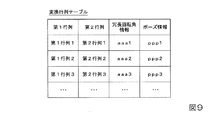
図9は、複数の第1行列及び第2行列が、冗長回転角情報と、ポーズ情報とに対応付けられて格納されている変換行列テーブルの一例を示す図である。図9に示したように、当該変換行列テーブルには、複数の第1行列及び第2行列が、冗長回転角情報と、ポーズ情報とに対応付けられて格納されている。当該変換行列テーブル内において、複数の第1行列及び第2行列のそれぞれは、第1行列及び第2行列に対応付けられた冗長回転角情報が示す冗長回転角と、ポーズ情報との少なくとも1つが互いに異なる。なお、変換行列テーブルには、冗長回転角情報と、ポーズ情報との一部が対応付けられた第1行列及び第2行列が格納されている構成であってもよく、冗長回転角情報と、ポーズ情報とのうち一方又は両方に代えて、他の情報が対応付けられた第1行列及び第2行列が格納されている構成であってもよい。 FIG. 9 is a diagram illustrating an example of a transformation matrix table in which a plurality of first matrices and second matrices are stored in association with redundant rotation angle information and pause information. As shown in FIG. 9, in the conversion matrix table, a plurality of first matrices and second matrices are stored in association with redundant rotation angle information and pause information. In the transformation matrix table, each of the plurality of first and second matrices has at least one of a redundant rotation angle indicated by redundant rotation angle information associated with the first matrix and the second matrix, and pause information. Different from each other. The conversion matrix table may be configured to store a first matrix and a second matrix in which a part of the redundant rotation angle information and the pose information is associated, and the redundant rotation angle information, Instead of one or both of the pause information, the first matrix and the second matrix associated with other information may be stored.
変換行列テーブルが図9に示したようなテーブルであった場合、図4に示したフローチャートにおけるステップS140において変換行列選択部364は、記憶部32に予め記憶された冗長回転角情報と、ポーズ情報とを読み出す。そして、変換行列選択部364は、記憶部32から読み出した変換行列テーブルの中から所定の第2条件を満たす1つのレコードを対象レコードとして選択する。所定の第2条件は、この一例において、以下に示す1A)〜3A)の3つの条件のすべてを満たすことである。なお、所定の第2条件は、当該3つの条件のうちの一部の条件を満たす構成であってもよく、当該3つの条件の一部又は全部に代えて、他の条件を満たす構成であってもよい。
When the transformation matrix table is a table as shown in FIG. 9, the transformation
1A)ステップS130において検出部370が検出した物体Oの位置及び姿勢に最も近い位置及び姿勢を表す第2行列を含むレコードであること。当該位置及び姿勢は、撮像部座標系CCにおける位置及び姿勢である。
2A)記憶部32に予め記憶された冗長回転角情報、すなわちユーザーから予め入力された冗長回転角情報が示す冗長回転角に最も近い冗長回転角を示す冗長回転角情報が対応付けられた第2行列を含むレコードであること。
3A)記憶部32に予め記憶されたポーズ情報、すなわちユーザーから予め入力されたポーズ情報と一致するポーズ情報が対応付けられた第2行列を含むレコードであること。
1A) A record including a second matrix representing the position and orientation closest to the position and orientation of the object O detected by the
2A) Secondly, redundant rotation angle information stored in advance in the
3A) A record including a second matrix in which pose information stored in advance in the
変換行列選択部364がステップS140において対象レコードを変換行列テーブルの中から選択した後、変換行列生成部367は、対象レコードに含まれる第1行列及び第2行列と、上記の式(1)とに基づいて変換行列を対象変換行列として生成する。そして、ステップS150において行列変換部365は、変換行列選択部364が生成した当該対象変換行列に基づいて、ステップS145において算出部363が算出した第1行列を第2行列に変換する変換処理を実行する。
After the transformation
このように、変換行列テーブルが図9に示したようなテーブルであった場合であっても、ロボット制御装置30は、撮像部10により撮像された撮像画像上の位置及び姿勢を表す撮像部座標系CCにおける物体Oの位置及び姿勢を表す第1行列を、ロボット座標系RCにおける物体Oの位置及び姿勢を表す第2行列に変換する変換行列を生成する。そして、ロボット制御装置30は、生成した変換行列に基づいて所定の作業を行う。これにより、ロボット20は、ロボット20が行う作業の精度を向上させることができる。
As described above, even when the transformation matrix table is a table as illustrated in FIG. 9, the
以上のように、ロボット20は、撮像部(この一例において、撮像部10)により撮像された撮像画像上の位置及び姿勢を表す撮像部座標系(この一例において、撮像部座標系CC)における対象物(この一例において、物体O)の位置及び姿勢を表す第1情報(この一例において、第1行列)を、第1座標系(この一例において、ロボット座標系RC)における当該対象物の位置及び姿勢を表す第2情報(この一例において、第2行列)に変換する変換情報(この一例において、変換行列)が複数あり、複数の変換情報の中から1つの変換情報を対象変換情報として選択し、選択した当該変換情報に基づいて所定の作業を行う。これにより、ロボット20は、ロボット20が行う作業の精度を向上させることができる。
As described above, the
また、ロボット20は、変換情報に対応付けられた位置情報が示す位置と、撮像画像から検出された対象物の撮像部座標系における位置とが最も近い変換情報を対象変換情報として選択する。これにより、ロボット20は、位置情報が対応付けられた変換情報に基づいて、ロボット20が行う作業の精度を向上させることができる。
In addition, the
また、ロボット20は、変換情報には更に、撮像部座標系における姿勢を示す姿勢情報が対応付けられており、変換情報に対応付けられた姿勢情報が示す姿勢と、撮像画像から検出された対象物の撮像部座標系における姿勢とが最も近い変換情報を対象変換情報として選択する。これにより、ロボット20は、姿勢情報が対応付けられた変換情報に基づいて、ロボット20が行う作業の精度を向上させることができる。
In addition, the
また、ロボット20は、変換情報に対応付けられた冗長回転角情報が示す冗長回転角と、予め入力された冗長回転角とが最も近い変換情報を対象変換情報として選択する。これにより、ロボット20は、冗長回転角情報が対応付けられた変換情報に基づいて、ロボット20が行う作業の精度を向上させることができる。
In addition, the
また、ロボット20は、変換情報に対応付けられたポーズ情報と、予め入力されたポーズ情報とが一致する変換情報を対象変換情報として選択する。これにより、ロボット20は、ポーズ情報が対応付けられた変換情報に基づいて、ロボット20が行う作業の精度を向上させることができる。
Further, the
また、ロボット20は、ロボット20が作業を行う領域(この一例において、作業領域RA)を複数の分割領域に分割し、分割領域に応じた複数の測定点毎に1以上の変換情報を生成する。これにより、ロボット20は、分割領域に応じた複数の測定点毎に生成された1以上の変換情報に基づいて、ロボット20が行う作業の精度を向上させることができる。
In addition, the
また、ロボット20は、測定点毎に、測定点にロボット20の制御点(この一例において、制御点T)を一致させてから変換情報を生成する処理を実行する。これにより、ロボット20は、測定点毎に実行された処理であって変換情報を生成する処理によって生成された変換情報に基づいて、ロボット20が行う作業の精度を向上させることができる。
In addition, the
また、ロボット20は、制御点の第1座標系における位置を保持したまま、制御点の第1座標系における姿勢を変更する毎に変換情報を生成する処理である。これにより、ロボット20は、測定点毎に、測定点にロボットの制御点を一致させた状態を保持したまま、制御点のロボット座標系における姿勢を変更する毎に変換情報を生成する処理によって生成された変換情報に基づいて、ロボットが行う作業の精度を向上させることができる。
In addition, the
また、ロボット20は、制御点のロボット座標系における位置を保持したまま、ロボット20が備える関節のうちの3つの旋回関節を結ぶことによって形成される三角形を含む平面である対象平面の基準平面に対する角度である冗長回転角を変更する毎に変換情報を生成する処理を実行する。これにより、ロボット20は、測定点毎に、測定点にロボットの制御点を一致させた状態を保持したまま、冗長回転角を変更する毎に変換情報を生成する処理によって生成された変換情報に基づいて、ロボット20が行う作業の精度を向上させることができる。
In addition, the
また、ロボット20は、ロボットが備える各関節のうちの回転角が互いに180°異なる2つの回転角のいずれであっても制御点の位置及び姿勢を第1位置及び第1姿勢と一致させることが可能な関節であるフリップ可能関節(この一例において、関節J2、関節J4、関節J6)の回転角を、互いに180°異なる2つの回転角のうちの小さい方の回転角と大きい方の回転角とのいずれかに変更する毎に変換情報を生成する処理を実行する。これにより、ロボット20は、測定点毎に、測定点にロボット20の制御点を一致させた状態を保持したまま、フリップ可能関節の回転角を変更する毎に変換情報を生成する処理によって生成された変換情報に基づいて、ロボット20が行う作業の精度を向上させることができる。
In addition, the
また、ロボット20は、変換情報に対応付けられた撮像位置姿勢情報が示す撮像位置姿勢と、予め入力された撮像位置姿勢とが一致する変換情報を対象変換情報として選択する。これにより、ロボット20は、撮像位置姿勢情報が対応付けられた変換情報に基づいて、ロボット20が行う作業の精度を向上させることができる。
Further, the
また、ロボット20は、撮像部により撮像された撮像画像上の位置及び姿勢を表す撮像部座標系における対象物の位置及び姿勢を表す第1行列を、ロボット座標系(この一例において、ロボット座標系RC)における当該対象物の位置及び姿勢を表す第2行列に変換する変換行列が複数あり、複数の変換行列の中から1つの変換行列を対象変換行列として選択し、選択した当該変換行列に基づいて所定の作業を行う。これにより、ロボット20は、ロボット20が行う作業の精度を向上させることができる。
In addition, the
以上、この発明の実施形態を、図面を参照して詳述してきたが、具体的な構成はこの実施形態に限られるものではなく、この発明の要旨を逸脱しない限り、変更、置換、削除等されてもよい。 The embodiment of the present invention has been described in detail with reference to the drawings. However, the specific configuration is not limited to this embodiment, and changes, substitutions, deletions, and the like are possible without departing from the gist of the present invention. May be.
また、以上に説明した装置(例えば、ロボット制御装置30)における任意の構成部の機能を実現するためのプログラムを、コンピューター読み取り可能な記録媒体に記録し、そのプログラムをコンピューターシステムに読み込ませて実行するようにしてもよい。なお、ここでいう「コンピューターシステム」とは、OS(Operating System)や周辺機器等のハードウェアを含むものとする。また、「コンピューター読み取り可能な記録媒体」とは、フレキシブルディスク、光磁気ディスク、ROM、CD(Compact Disk)−ROM等の可搬媒体、コンピューターシステムに内蔵されるハードディスク等の記憶装置のことをいう。さらに「コンピューター読み取り可能な記録媒体」とは、インターネット等のネットワークや電話回線等の通信回線を介してプログラムが送信された場合のサーバーやクライアントとなるコンピューターシステム内部の揮発性メモリー(RAM)のように、一定時間プログラムを保持しているものも含むものとする。 Further, a program for realizing the function of an arbitrary component in the above-described apparatus (for example, robot control apparatus 30) is recorded on a computer-readable recording medium, and the program is read into a computer system and executed. You may make it do. Here, the “computer system” includes hardware such as an OS (Operating System) and peripheral devices. The “computer-readable recording medium” refers to a portable medium such as a flexible disk, a magneto-optical disk, a ROM, a CD (Compact Disk) -ROM, or a storage device such as a hard disk built in the computer system. . Furthermore, “computer-readable recording medium” means a volatile memory (RAM) inside a computer system that becomes a server or client when a program is transmitted via a network such as the Internet or a communication line such as a telephone line. In addition, those holding programs for a certain period of time are also included.
また、上記のプログラムは、このプログラムを記憶装置等に格納したコンピューターシステムから、伝送媒体を介して、あるいは、伝送媒体中の伝送波により他のコンピューターシステムに伝送されてもよい。ここで、プログラムを伝送する「伝送媒体」は、インターネット等のネットワーク(通信網)や電話回線等の通信回線(通信線)のように情報を伝送する機能を有する媒体のことをいう。
また、上記のプログラムは、前述した機能の一部を実現するためのものであってもよい。さらに、上記のプログラムは、前述した機能をコンピューターシステムにすでに記録されているプログラムとの組み合わせで実現できるもの、いわゆる差分ファイル(差分プログラム)であってもよい。
In addition, the above program may be transmitted from a computer system storing the program in a storage device or the like to another computer system via a transmission medium or by a transmission wave in the transmission medium. Here, the “transmission medium” for transmitting the program refers to a medium having a function of transmitting information, such as a network (communication network) such as the Internet or a communication line (communication line) such as a telephone line.
Further, the above program may be for realizing a part of the functions described above. Further, the program may be a so-called difference file (difference program) that can realize the above-described functions in combination with a program already recorded in the computer system.
1…ロボットシステム、20…ロボット、30…ロボット制御装置、31…CPU、32…記憶部、33…入力受付部、34…通信部、35…表示部、36…制御部、361…撮像制御部、362…画像取得部、363…算出部、364…変換行列選択部、365…行列変換部、366…回転角情報取得部、367…変換行列生成部、368…記憶制御部、369…ロボット制御部、370…検出部
DESCRIPTION OF
Claims (14)
ロボット。 First information representing the position and orientation of the object in the imaging unit coordinate system representing the position and orientation on the captured image captured by the imaging unit, and second information representing the position and orientation of the object in the first coordinate system. A plurality of pieces of conversion information to be converted, and one conversion information is selected as target conversion information from among the plurality of conversion information, and a predetermined operation is performed based on the selected conversion information.
robot.
前記変換情報に対応付けられた前記位置情報が示す位置と、前記撮像画像から検出された前記対象物の前記撮像部座標系における位置とが最も近い前記変換情報を前記対象変換情報として選択する、
請求項1に記載のロボット。 The conversion information is associated with position information indicating a position in the imaging unit coordinate system,
Selecting the conversion information closest to the position indicated by the position information associated with the conversion information and the position of the object detected from the captured image in the imaging unit coordinate system as the target conversion information;
The robot according to claim 1.
前記変換情報に対応付けられた前記姿勢情報が示す姿勢と、前記撮像画像から検出された前記対象物の前記撮像部座標系における姿勢とが最も近い前記変換情報を前記対象変換情報として選択する、
請求項2に記載のロボット。 The conversion information is further associated with posture information indicating a posture in the imaging unit coordinate system,
Selecting the conversion information closest to the posture indicated by the posture information associated with the conversion information and the posture of the object detected from the captured image in the imaging unit coordinate system, as the target conversion information;
The robot according to claim 2.
前記変換情報には更に、前記ロボットが備える関節のうちの3つの旋回関節を結ぶことによって形成される三角形を含む平面である対象平面の基準平面に対する角度である冗長回転角を示す冗長回転角情報が対応付けられており、
前記変換情報に対応付けられた前記冗長回転角情報が示す前記冗長回転角と、予め入力された前記冗長回転角とが最も近い前記変換情報を前記対象変換情報として選択する、
請求項2又は3に記載のロボット。 Have 7 or more joints,
The conversion information further includes redundant rotation angle information indicating a redundant rotation angle that is an angle with respect to a reference plane of a target plane that is a plane including a triangle formed by connecting three revolving joints of the joints of the robot. Are associated,
Selecting the conversion information closest to the redundant rotation angle indicated by the redundant rotation angle information associated with the conversion information and the previously input redundant rotation angle as the target conversion information;
The robot according to claim 2 or 3.
前記変換情報に対応付けられた前記ポーズ情報と、予め入力された前記ポーズ情報とが一致する前記変換情報を前記対象変換情報として選択する、
請求項2から4のうちいずれか一項に記載のロボット。 In the conversion information, the position and posture of the control point are made to coincide with the first position and the first posture even if the rotation angle of each joint included in the robot is any of two rotation angles different from each other by 180 °. The pose information indicating whether the rotation angle of the flipable joint, which is a possible joint, is the smaller rotation angle or the larger rotation angle of two rotation angles that are 180 ° different from each other is associated And
Selecting the conversion information in which the pose information associated with the conversion information matches the pose information input in advance as the target conversion information;
The robot according to any one of claims 2 to 4.
請求項1から5のうちいずれか一項に記載のロボット。 Dividing the area where the robot performs the work into a plurality of divided areas, and generating one or more pieces of conversion information for each of a plurality of measurement points according to the divided areas;
The robot according to any one of claims 1 to 5.
請求項6に記載のロボット。 For each measurement point, execute the process of generating the conversion information after matching the control point of the robot to the measurement point.
The robot according to claim 6.
請求項7に記載のロボット。 The process is a process of generating the conversion information every time the posture of the control point in the first coordinate system is changed while maintaining the position of the control point of the robot in the first coordinate system.
The robot according to claim 7.
前記処理は、前記制御点の前記第1座標系における位置を保持したまま、前記ロボットが備える関節のうちの3つの旋回関節を結ぶことによって形成される三角形を含む平面である対象平面の基準平面に対する角度である冗長回転角を変更する毎に前記変換情報を生成する処理である、
請求項7又は8に記載のロボット。 Have 7 or more joints,
In the processing, a reference plane of a target plane that is a plane including a triangle formed by connecting three turning joints among the joints of the robot while maintaining the position of the control point in the first coordinate system. Each time the redundant rotation angle that is an angle with respect to is changed, the conversion information is generated.
The robot according to claim 7 or 8.
請求項7から9のうちいずれか一項に記載のロボット。 In the processing, while maintaining the position of the control point in the first coordinate system, the position of the control point is any one of two rotation angles that are 180 ° different from each other in the rotation angle of each joint included in the robot. And the rotation angle of the flippable joint, which is a joint capable of matching the posture with the first position and the first posture, is the smaller rotation angle and the larger rotation angle of two rotation angles different from each other by 180 °. Is a process of generating the conversion information every time it is changed to
The robot according to any one of claims 7 to 9.
前記変換情報に対応付けられた前記撮像位置姿勢情報が示す前記撮像位置姿勢と、予め入力された前記撮像位置姿勢とが一致する前記変換情報を前記対象変換情報として選択する、
請求項2から10のうちいずれか一項に記載のロボット。 The conversion information is further associated with imaging position / orientation information indicating an imaging position / orientation that is the position and orientation of the imaging unit in the first coordinate system,
Selecting the conversion information in which the imaging position and orientation indicated by the imaging position and orientation information associated with the conversion information match the imaging position and orientation input in advance as the target conversion information;
The robot according to any one of claims 2 to 10.
前記第2情報は、第2行列であり、
前記変換情報は、変換行列であり、
前記第1座標系は、ロボット座標系である、
請求項1から11のうちいずれか一項に記載のロボット。 The first information is a first matrix;
The second information is a second matrix;
The conversion information is a conversion matrix;
The first coordinate system is a robot coordinate system;
The robot according to any one of claims 1 to 11.
ロボット制御装置。 First information representing the position and orientation of the object in the imaging unit coordinate system representing the position and orientation on the captured image captured by the imaging unit, and second information representing the position and orientation of the object in the first coordinate system. A plurality of pieces of conversion information to be converted into, selecting one piece of the conversion information as target conversion information from the plurality of pieces of conversion information, and causing the robot to perform a predetermined operation based on the selected conversion information;
Robot control device.
ロボットと、
前記撮像部により撮像された撮像画像上の位置及び姿勢を表す撮像部座標系における対象物の位置及び姿勢を表す第1情報を、第1座標系における前記対象物の位置及び姿勢を表す第2情報に変換する変換情報が複数あり、前記複数の前記変換情報の中から1つの前記変換情報を対象変換情報として選択し、選択した当該変換情報に基づいて所定の作業を前記ロボットに行わせるロボット制御装置と、
を備えるロボットシステム。 An imaging unit;
With robots,
The first information representing the position and orientation of the object in the imaging unit coordinate system representing the position and orientation on the captured image captured by the imaging unit is the second information representing the position and orientation of the object in the first coordinate system. A plurality of conversion information to be converted into information, a robot that selects one of the plurality of conversion information as the target conversion information, and causes the robot to perform a predetermined work based on the selected conversion information A control device;
A robot system comprising:
Priority Applications (2)
| Application Number | Priority Date | Filing Date | Title |
|---|---|---|---|
| JP2016059673A JP2017170571A (en) | 2016-03-24 | 2016-03-24 | Robot, robot control apparatus, and robot system |
| US15/464,703 US20170277167A1 (en) | 2016-03-24 | 2017-03-21 | Robot system, robot control device, and robot |
Applications Claiming Priority (1)
| Application Number | Priority Date | Filing Date | Title |
|---|---|---|---|
| JP2016059673A JP2017170571A (en) | 2016-03-24 | 2016-03-24 | Robot, robot control apparatus, and robot system |
Publications (2)
| Publication Number | Publication Date |
|---|---|
| JP2017170571A true JP2017170571A (en) | 2017-09-28 |
| JP2017170571A5 JP2017170571A5 (en) | 2019-04-11 |
Family
ID=59898646
Family Applications (1)
| Application Number | Title | Priority Date | Filing Date |
|---|---|---|---|
| JP2016059673A Withdrawn JP2017170571A (en) | 2016-03-24 | 2016-03-24 | Robot, robot control apparatus, and robot system |
Country Status (2)
| Country | Link |
|---|---|
| US (1) | US20170277167A1 (en) |
| JP (1) | JP2017170571A (en) |
Cited By (1)
| Publication number | Priority date | Publication date | Assignee | Title |
|---|---|---|---|---|
| JP2020075325A (en) * | 2018-11-08 | 2020-05-21 | 株式会社Ihi | Tool center point setting method and setting device |
Families Citing this family (9)
| Publication number | Priority date | Publication date | Assignee | Title |
|---|---|---|---|---|
| CN110472497A (en) * | 2019-07-08 | 2019-11-19 | 西安工程大学 | A kind of motion characteristic representation method merging rotation amount |
| CN113001537B (en) * | 2019-12-20 | 2022-08-02 | 深圳市优必选科技股份有限公司 | Mechanical arm control method, mechanical arm control device and terminal equipment |
| US11530052B1 (en) | 2020-02-17 | 2022-12-20 | Amazon Technologies, Inc. | Systems and methods for automated ground handling of aerial vehicles |
| US11597092B1 (en) | 2020-03-26 | 2023-03-07 | Amazon Technologies, Ine. | End-of-arm tool with a load cell |
| US11534924B1 (en) | 2020-07-21 | 2022-12-27 | Amazon Technologies, Inc. | Systems and methods for generating models for automated handling of vehicles |
| US11534915B1 (en) | 2020-08-05 | 2022-12-27 | Amazon Technologies, Inc. | Determining vehicle integrity based on observed behavior during predetermined manipulations |
| JP2022181762A (en) * | 2021-05-27 | 2022-12-08 | 株式会社東芝 | Work supporting device, work supporting method, and work supporting program |
| CN114425155A (en) * | 2022-01-26 | 2022-05-03 | 北京市商汤科技开发有限公司 | Data processing method and device, computer equipment and computer storage medium |
| CN115793698A (en) * | 2023-02-07 | 2023-03-14 | 北京四维远见信息技术有限公司 | Automatic attitude control system and method |
Citations (7)
| Publication number | Priority date | Publication date | Assignee | Title |
|---|---|---|---|---|
| JPH06175716A (en) * | 1992-12-10 | 1994-06-24 | Fanuc Ltd | Position/attitude correcting method for object holding work of manipulator |
| JPH07132474A (en) * | 1993-11-02 | 1995-05-23 | Fujitsu Ltd | Manipulator control device |
| JP2009148850A (en) * | 2007-12-20 | 2009-07-09 | Denso Wave Inc | Motion control device for robot and its motion control method |
| JP2009226552A (en) * | 2008-03-24 | 2009-10-08 | Nissan Motor Co Ltd | Method for teaching redundant robot |
| JP2013526423A (en) * | 2010-05-14 | 2013-06-24 | コグネックス・テクノロジー・アンド・インベストメント・コーポレーション | Apparatus and method for robust calibration between machine vision system and robot |
| US20150094855A1 (en) * | 2012-05-04 | 2015-04-02 | Leoni Cia Cable Systems Sas | Imitation learning method for a multi-axis manipulator |
| JP2015199155A (en) * | 2014-04-07 | 2015-11-12 | キヤノン株式会社 | Information processing device, information processing method, and program |
-
2016
- 2016-03-24 JP JP2016059673A patent/JP2017170571A/en not_active Withdrawn
-
2017
- 2017-03-21 US US15/464,703 patent/US20170277167A1/en not_active Abandoned
Patent Citations (7)
| Publication number | Priority date | Publication date | Assignee | Title |
|---|---|---|---|---|
| JPH06175716A (en) * | 1992-12-10 | 1994-06-24 | Fanuc Ltd | Position/attitude correcting method for object holding work of manipulator |
| JPH07132474A (en) * | 1993-11-02 | 1995-05-23 | Fujitsu Ltd | Manipulator control device |
| JP2009148850A (en) * | 2007-12-20 | 2009-07-09 | Denso Wave Inc | Motion control device for robot and its motion control method |
| JP2009226552A (en) * | 2008-03-24 | 2009-10-08 | Nissan Motor Co Ltd | Method for teaching redundant robot |
| JP2013526423A (en) * | 2010-05-14 | 2013-06-24 | コグネックス・テクノロジー・アンド・インベストメント・コーポレーション | Apparatus and method for robust calibration between machine vision system and robot |
| US20150094855A1 (en) * | 2012-05-04 | 2015-04-02 | Leoni Cia Cable Systems Sas | Imitation learning method for a multi-axis manipulator |
| JP2015199155A (en) * | 2014-04-07 | 2015-11-12 | キヤノン株式会社 | Information processing device, information processing method, and program |
Cited By (2)
| Publication number | Priority date | Publication date | Assignee | Title |
|---|---|---|---|---|
| JP2020075325A (en) * | 2018-11-08 | 2020-05-21 | 株式会社Ihi | Tool center point setting method and setting device |
| JP7172466B2 (en) | 2018-11-08 | 2022-11-16 | 株式会社Ihi | Tool center point setting method and setting device |
Also Published As
| Publication number | Publication date |
|---|---|
| US20170277167A1 (en) | 2017-09-28 |
Similar Documents
| Publication | Publication Date | Title |
|---|---|---|
| JP2017170571A (en) | Robot, robot control apparatus, and robot system | |
| US10589424B2 (en) | Robot control device, robot, and robot system | |
| JP6380828B2 (en) | Robot, robot system, control device, and control method | |
| JP6733239B2 (en) | Controller and robot system | |
| JP6427972B2 (en) | Robot, robot system and control device | |
| US20160184996A1 (en) | Robot, robot system, control apparatus, and control method | |
| JP2017071018A (en) | Robot system, robot, and robot controlling device | |
| JP6897396B2 (en) | Control devices, robot systems and control methods | |
| US20180085920A1 (en) | Robot control device, robot, and robot system | |
| JP5223407B2 (en) | Redundant robot teaching method | |
| US20180215044A1 (en) | Image processing device, robot control device, and robot | |
| JP6665450B2 (en) | Robot, control device, and robot system | |
| JP6455869B2 (en) | Robot, robot system, control device, and control method | |
| JP2015182212A (en) | Robot system, robot, control device, and control method | |
| JP2017202549A (en) | Robot control device, robot, and robot system | |
| JP2016120530A (en) | Robot and robot calibration system | |
| JP7249221B2 (en) | SENSOR POSITION AND POSTURE CALIBRATION DEVICE AND SENSOR POSITION AND POSTURE CALIBRATION METHOD | |
| JP2018017610A (en) | Three-dimensional measuring device, robot, robot controlling device, and robot system | |
| JP2022163836A (en) | Method for displaying robot image, computer program, and method for displaying robot image | |
| JP2017219359A (en) | Shape measuring device, robot controller, and robot | |
| JP2019111588A (en) | Robot system, information processor, and program | |
| JP2018001321A (en) | Robot, robot control device and robot system | |
| JP2016013610A (en) | Robot, and control method | |
| JP7447568B2 (en) | Simulation equipment and programs | |
| JP2017100197A (en) | Robot and control method |
Legal Events
| Date | Code | Title | Description |
|---|---|---|---|
| RD05 | Notification of revocation of power of attorney |
Free format text: JAPANESE INTERMEDIATE CODE: A7425 Effective date: 20180906 |
|
| RD03 | Notification of appointment of power of attorney |
Free format text: JAPANESE INTERMEDIATE CODE: A7423 Effective date: 20181119 |
|
| A521 | Request for written amendment filed |
Free format text: JAPANESE INTERMEDIATE CODE: A523 Effective date: 20190304 |
|
| A621 | Written request for application examination |
Free format text: JAPANESE INTERMEDIATE CODE: A621 Effective date: 20190304 |
|
| A977 | Report on retrieval |
Free format text: JAPANESE INTERMEDIATE CODE: A971007 Effective date: 20200205 |
|
| A131 | Notification of reasons for refusal |
Free format text: JAPANESE INTERMEDIATE CODE: A131 Effective date: 20200212 |
|
| A761 | Written withdrawal of application |
Free format text: JAPANESE INTERMEDIATE CODE: A761 Effective date: 20200413 |