JP6665450B2 - Robot, control device, and robot system - Google Patents
Robot, control device, and robot system Download PDFInfo
- Publication number
- JP6665450B2 JP6665450B2 JP2015170162A JP2015170162A JP6665450B2 JP 6665450 B2 JP6665450 B2 JP 6665450B2 JP 2015170162 A JP2015170162 A JP 2015170162A JP 2015170162 A JP2015170162 A JP 2015170162A JP 6665450 B2 JP6665450 B2 JP 6665450B2
- Authority
- JP
- Japan
- Prior art keywords
- robot
- inclination
- unit
- angle
- control device
- Prior art date
- Legal status (The legal status is an assumption and is not a legal conclusion. Google has not performed a legal analysis and makes no representation as to the accuracy of the status listed.)
- Active
Links
Images


Classifications
-
- B—PERFORMING OPERATIONS; TRANSPORTING
- B25—HAND TOOLS; PORTABLE POWER-DRIVEN TOOLS; MANIPULATORS
- B25J—MANIPULATORS; CHAMBERS PROVIDED WITH MANIPULATION DEVICES
- B25J9/00—Programme-controlled manipulators
- B25J9/16—Programme controls
- B25J9/1628—Programme controls characterised by the control loop
- B25J9/1633—Programme controls characterised by the control loop compliant, force, torque control, e.g. combined with position control
-
- B—PERFORMING OPERATIONS; TRANSPORTING
- B25—HAND TOOLS; PORTABLE POWER-DRIVEN TOOLS; MANIPULATORS
- B25J—MANIPULATORS; CHAMBERS PROVIDED WITH MANIPULATION DEVICES
- B25J13/00—Controls for manipulators
- B25J13/08—Controls for manipulators by means of sensing devices, e.g. viewing or touching devices
- B25J13/088—Controls for manipulators by means of sensing devices, e.g. viewing or touching devices with position, velocity or acceleration sensors
- B25J13/089—Determining the position of the robot with reference to its environment
-
- B—PERFORMING OPERATIONS; TRANSPORTING
- B25—HAND TOOLS; PORTABLE POWER-DRIVEN TOOLS; MANIPULATORS
- B25J—MANIPULATORS; CHAMBERS PROVIDED WITH MANIPULATION DEVICES
- B25J13/00—Controls for manipulators
- B25J13/08—Controls for manipulators by means of sensing devices, e.g. viewing or touching devices
- B25J13/085—Force or torque sensors
-
- B—PERFORMING OPERATIONS; TRANSPORTING
- B25—HAND TOOLS; PORTABLE POWER-DRIVEN TOOLS; MANIPULATORS
- B25J—MANIPULATORS; CHAMBERS PROVIDED WITH MANIPULATION DEVICES
- B25J9/00—Programme-controlled manipulators
- B25J9/16—Programme controls
- B25J9/1694—Programme controls characterised by use of sensors other than normal servo-feedback from position, speed or acceleration sensors, perception control, multi-sensor controlled systems, sensor fusion
-
- G—PHYSICS
- G05—CONTROLLING; REGULATING
- G05B—CONTROL OR REGULATING SYSTEMS IN GENERAL; FUNCTIONAL ELEMENTS OF SUCH SYSTEMS; MONITORING OR TESTING ARRANGEMENTS FOR SUCH SYSTEMS OR ELEMENTS
- G05B2219/00—Program-control systems
- G05B2219/30—Nc systems
- G05B2219/39—Robotics, robotics to robotics hand
- G05B2219/39056—On line relative position error and orientation error calibration
-
- G—PHYSICS
- G05—CONTROLLING; REGULATING
- G05B—CONTROL OR REGULATING SYSTEMS IN GENERAL; FUNCTIONAL ELEMENTS OF SUCH SYSTEMS; MONITORING OR TESTING ARRANGEMENTS FOR SUCH SYSTEMS OR ELEMENTS
- G05B2219/00—Program-control systems
- G05B2219/30—Nc systems
- G05B2219/39—Robotics, robotics to robotics hand
- G05B2219/39177—Compensation position working point as function of inclination tool, hand
-
- G—PHYSICS
- G05—CONTROLLING; REGULATING
- G05B—CONTROL OR REGULATING SYSTEMS IN GENERAL; FUNCTIONAL ELEMENTS OF SUCH SYSTEMS; MONITORING OR TESTING ARRANGEMENTS FOR SUCH SYSTEMS OR ELEMENTS
- G05B2219/00—Program-control systems
- G05B2219/30—Nc systems
- G05B2219/40—Robotics, robotics mapping to robotics vision
- G05B2219/40042—Control tilting angle of surface carried by robot
Description
この発明は、ロボット、制御装置、及びロボットシステムに関する。 The present invention relates to a robot, a control device, and a robot system.
ロボットに物体を把持させ、所定の作業を行わせる技術の研究や開発が行われている。 2. Description of the Related Art Research and development of a technique for causing a robot to grasp an object and perform a predetermined operation have been performed.
これに関し、傾斜計を用いることにより、重力方向に垂直な平面に対して水平な方向にアームを動作させる制御方法が知られている(特許文献1参照)。 In this regard, a control method is known in which an inclinometer is used to move an arm in a direction horizontal to a plane perpendicular to the direction of gravity (see Patent Document 1).
しかしながら、従来の制御方法では、ワークにおいて作業が行われる面である作業平面を重力方向に垂直な平面に対して水平にすることができなかった。このため、当該制御方法では、アームを当該平面に対して水平に移動させることができたとしても、作業平面が当該平面に対して傾いている場合、作業平面が当該平面に対して水平な状態で行われなければならない作業に誤差が生じ、当該作業を失敗してしまう場合があった。 However, according to the conventional control method, a work plane, which is a surface on which work is performed on the work, cannot be made horizontal with respect to a plane perpendicular to the direction of gravity. For this reason, in the control method, even if the arm can be moved horizontally with respect to the plane, when the work plane is inclined with respect to the plane, the work plane is horizontal with respect to the plane. There is a case where an error occurs in the work that must be performed in the above, and the work is failed.
上記課題の少なくとも一つを解決するために本発明の一態様は、アームを備え、前記アームに設けられる把持部又は前記把持部により把持される物体には、第1傾斜計が設けられ、基準面の第1角度と、前記第1傾斜計により計測された第2角度とに基づいて前記アームを動作させる、ロボットである。
この構成により、ロボットは、基準面の第1角度と、第1傾斜計により計測された第2角度とに基づいてアームを動作させる。これにより、ロボットは、基準面と第2角度とに応じた動作によって物体を移動させることができる。
One embodiment of the present invention for solving at least one of the above-described problems includes an arm, and a gripper provided on the arm or an object gripped by the gripper is provided with a first inclinometer; A robot that operates the arm based on a first angle of a surface and a second angle measured by the first inclinometer.
With this configuration, the robot operates the arm based on the first angle of the reference plane and the second angle measured by the first inclinometer. Thus, the robot can move the object by an operation according to the reference plane and the second angle.
また、本発明の他の態様は、ロボットにおいて、第1角度を第1傾斜計により計測する、構成が用いられてもよい。
この構成により、ロボットは、第1角度を第1傾斜計により計測する。これにより、ロボットは、第1傾斜計により計測された第1角度及び第2角度と基準面と基づく動作によって物体を移動させることができる。
In another aspect of the present invention, a configuration in which the first angle is measured by the first inclinometer in the robot may be used.
With this configuration, the robot measures the first angle with the first inclinometer. Accordingly, the robot can move the object by an operation based on the first angle and the second angle measured by the first inclinometer and the reference plane.
また、本発明の他の態様は、ロボットにおいて、前記基準面に前記物体の所定面又は前記把持部の所定面を接面させた状態において前記第1角度を前記第1傾斜計により計測する、構成が用いられてもよい。
この構成により、ロボットは、基準面に物体の所定面又は把持部の所定面を接面させた状態において第1角度を第1傾斜計により計測する。これにより、ロボットは、基準面に物体の所定面又は把持部の所定面を接面させた状態において第1傾斜計により計測された第1角度と第2角度に基づく動作によって物体を移動させることができる。
In another aspect of the present invention, in the robot, the first angle is measured by the first inclinometer in a state where a predetermined surface of the object or a predetermined surface of the grip portion is in contact with the reference surface. Configurations may be used.
With this configuration, the robot measures the first angle with the first inclinometer in a state where the predetermined surface of the object or the predetermined surface of the grip portion is in contact with the reference surface. Accordingly, the robot moves the object by an operation based on the first angle and the second angle measured by the first inclinometer in a state where the predetermined surface of the object or the predetermined surface of the grip portion is in contact with the reference surface. Can be.
また、本発明の他の態様は、ロボットにおいて、前記アームは、力を検出する力検出器を備え、前記力検出器の出力に基づいて、前記基準面に前記物体の所定面又は前記把持部の所定面を接面させる、構成が用いられてもよい。
この構成により、ロボットは、力検出器の出力に基づいて、基準面に物体の所定面又は把持部の所定面を接面させる。これにより、ロボットは、力検出器の出力に基づいて物体の所定面又は把持部の所定面が基準面に接面させた状態を用いて、物体を移動させることができる。
According to another aspect of the present invention, in the robot, the arm includes a force detector for detecting a force, and based on an output of the force detector, a predetermined surface of the object or the gripping portion on the reference surface. A configuration may be used in which the predetermined surface is brought into contact.
With this configuration, the robot causes the predetermined surface of the object or the predetermined surface of the grip portion to contact the reference surface based on the output of the force detector. Accordingly, the robot can move the object using a state in which the predetermined surface of the object or the predetermined surface of the grip portion is in contact with the reference surface based on the output of the force detector.
また、本発明の他の態様は、ロボットにおいて、前記第1角度を、前記第1傾斜計とは異なる第2傾斜計により計測する、構成が用いられてもよい。
この構成により、ロボットは、第1角度を、第1傾斜計とは異なる第2傾斜計により計測する。これにより、ロボットは、第2傾斜計により計測された第1角度と、第1傾斜計により計測された第2角度とに基づいて、基準面に応じた動作によって物体を移動させることができる。
In another aspect of the present invention, in the robot, a configuration may be used in which the first angle is measured by a second inclinometer different from the first inclinometer.
With this configuration, the robot measures the first angle using the second inclinometer different from the first inclinometer. Thereby, the robot can move the object by an operation according to the reference plane based on the first angle measured by the second inclinometer and the second angle measured by the first inclinometer.
また、本発明の他の態様は、ロボットにおいて、前記アームの少なくとも一部を、前記基準面に対して水平に移動させる、構成が用いられてもよい。
この構成により、ロボットは、アームの少なくとも一部を、基準面に対して水平に移動させる。これにより、ロボットは、物体を基準面に対して水平に移動させることができる。
In another aspect of the present invention, in the robot, at least a part of the arm may be moved horizontally with respect to the reference plane.
With this configuration, the robot moves at least a part of the arm horizontally with respect to the reference plane. Thus, the robot can move the object horizontally with respect to the reference plane.
また、本発明の他の態様は、ロボットにおいて、前記基準面に平行な面には、加工装置が設けられ、前記物体は、前記加工装置により加工されるワークである、構成が用いられてもよい。
この構成により、ロボットは、基準面を用いて計測された第1角度と、加工装置により加工されるワーク又は把持部に設けられた第1傾斜計により計測された第2角度とに基づいてアームを動作させる。これにより、ロボットは、基準面に応じた動作によって加工装置により加工されるワークを移動させることができる。
In another aspect of the present invention, in the robot, a processing device is provided on a surface parallel to the reference surface, and the object is a workpiece processed by the processing device. Good.
With this configuration, the robot is configured to arm based on the first angle measured by using the reference plane and the second angle measured by the first inclinometer provided on the workpiece or the gripper processed by the processing device. To work. Thereby, the robot can move the workpiece processed by the processing device by the operation according to the reference plane.
また、本発明の他の態様は、ロボットにおいて、撮像部を備え、前記撮像部により撮像された撮像画像に基づいて、前記把持部と前記物体との位置関係を変更する、構成が用いられてもよい。
この構成により、ロボットは、撮像部により撮像された撮像画像に基づいて、把持部と物体との位置関係を変更する。これにより、ロボットは、把持部と物体との位置関係がずれてしまった場合であっても、ずれる前の位置関係に戻すことができる。
Further, another aspect of the present invention employs a configuration in which the robot includes an imaging unit, and changes a positional relationship between the gripping unit and the object based on an image captured by the imaging unit. Is also good.
With this configuration, the robot changes the positional relationship between the grasping unit and the object based on the image captured by the imaging unit. Thus, even if the positional relationship between the gripper and the object is shifted, the robot can return to the positional relationship before the shift.
また、本発明の他の態様は、ロボットにおいて、所定の条件が満たされた場合、前記第1角度を再計測する、構成が用いられてもよい。
この構成により、ロボットは、所定の条件が満たされた場合、第1角度を再計測する。これにより、ロボットは、第1角度がずれている可能性が高い場合に、第1角度を再計測することができる。
In another aspect of the present invention, a configuration may be used in which, when a predetermined condition is satisfied, the first angle is measured again in the robot.
With this configuration, the robot measures the first angle again when a predetermined condition is satisfied. Accordingly, the robot can re-measure the first angle when the possibility that the first angle is shifted is high.
また、本発明の他の態様は、ロボットにおいて、前記物体の所定面又は前記把持部の所定面と、前記第1傾斜計の所定面との基準の位置関係からのずれを補正する、構成が用いられてもよい。
この構成により、ロボットは、物体の所定面又は把持部の所定面と、第1傾斜計の所定面との基準の位置関係からのずれを補正する。これにより、ロボットは、補正した当該位置関係に基づいて、基準面に応じた動作によって物体を移動させることができる。
According to another aspect of the present invention, in the robot, a deviation from a reference positional relationship between the predetermined surface of the object or the predetermined surface of the gripper and the predetermined surface of the first inclinometer is corrected. May be used.
With this configuration, the robot corrects a deviation from a reference positional relationship between the predetermined surface of the object or the predetermined surface of the gripper and the predetermined surface of the first inclinometer. Thereby, the robot can move the object by the operation according to the reference plane based on the corrected positional relationship.
また、本発明の他の態様は、上記のいずれかに記載のロボットの動作を行うようにロボットを制御する、制御装置である。
この構成により、制御装置は、基準面を用いて計測された第1角度と、第1傾斜計により計測された第2角度とに基づいてアームを動作させる。これにより、制御装置は、基準面に応じた動作によって物体を移動させることができる。
Another aspect of the present invention is a control device for controlling a robot so as to perform any of the operations of the robot described above.
With this configuration, the control device operates the arm based on the first angle measured using the reference plane and the second angle measured by the first inclinometer. Thereby, the control device can move the object by the operation according to the reference plane.
また、本発明の他の態様は、上記のいずれかに記載のロボットと、上記に記載の制御装置と、を備えるロボットシステムである。
この構成により、ロボットシステムは、基準面を用いて計測された第1角度と、第1傾斜計により計測された第2角度とに基づいてアームを動作させる。これにより、ロボットシステムは、基準面に応じた動作によって物体を移動させることができる。
Another aspect of the present invention is a robot system including any one of the above-described robots and the above-described control device.
With this configuration, the robot system operates the arm based on the first angle measured using the reference plane and the second angle measured by the first inclinometer. Thereby, the robot system can move the object by the operation according to the reference plane.
以上により、ロボット、制御装置、及びロボットシステムは、基準面を用いて計測された第1角度と、第1傾斜計により計測された第2角度とに基づいてアームを動作させる。これにより、ロボット、制御装置、及びロボットシステムは、基準面に応じた動作によって物体を移動させることができる。 As described above, the robot, the control device, and the robot system operate the arm based on the first angle measured using the reference plane and the second angle measured by the first inclinometer. Thereby, the robot, the control device, and the robot system can move the object by the operation according to the reference plane.
<実施形態>
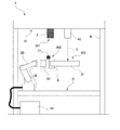
以下、本発明の実施形態について、図面を参照して説明する。図1は、本実施形態に係るロボットシステム1の一例を示す構成図である。ロボットシステム1は、ロボット20と、制御装置30を備える。
<Embodiment>
Hereinafter, embodiments of the present invention will be described with reference to the drawings. FIG. 1 is a configuration diagram illustrating an example of a
まず、ロボットシステム1が備えるロボット20の構成について説明する。
ロボット20は、単腕ロボットである。単腕ロボットは、1本のアーム(腕)を備えるロボットである。なお、ロボット20は、単腕ロボットに代えて、複腕ロボットであってもよい。複腕ロボットは、2本以上のアームを備えるロボットである。図1に示したような2本のアームを備える双腕ロボットは、複腕ロボットの一例である。
First, the configuration of the
The
アームは、エンドエフェクターEと、マニピュレーターMと、第1傾斜計測部21と、力検出部22を備える。
The arm includes an end effector E, a manipulator M, a first
エンドエフェクターEは、物体を把持可能な2以上の爪部と、第1傾斜計測部21と、図示しない複数のアクチュエーターを備える。エンドエフェクターEが備える複数のアクチュエーターはそれぞれ、ケーブルによって制御装置30と通信可能に接続されている。これにより、当該アクチュエーターは、制御装置30から取得される制御信号に基づいて、2以上の爪部のそれぞれを動作させる。ケーブルを介した有線通信は、例えば、イーサネット(登録商標)やUSB(Universal Serial Bus)等の規格によって行われる。なお、当該アクチュエーターは、Wi−Fi(登録商標)等の通信規格により行われる無線通信によって制御装置30と接続される構成であってもよい。
The end effector E includes two or more claws capable of gripping an object, a first
エンドエフェクターEは、マニピュレーターMと着脱可能な構成であってもよい。また、エンドエフェクターEは、物体を把持可能な2以上の爪部を備える構成に代えて、物体を空気や磁気によって吸着可能な吸着部を備える構成であってもよい。エンドエフェクターEは、把持部の一例である。 The end effector E may be configured to be detachable from the manipulator M. Further, the end effector E may be configured to include an adsorbing section that can adsorb the object by air or magnetism, instead of the configuration including the two or more claws that can grip the object. The end effector E is an example of a grip.
第1傾斜計測部21は、エンドエフェクターEの一部に設けられた面であるハンド面M2上に備えられる。ハンド面M2は、把持部の所定面の一例である。第1傾斜計測部21は、ロボット座標系におけるXY平面に対するハンド面M2の傾きを計測するセンサーである。なお、第1傾斜計測部21は、当該XY平面に対するハンド面M2の傾きを示す角度を計測する構成に代えて、他の面に対するハンド面M2の傾きを示す角度を計測する構成であってもよい。
The first
ハンド面M2の傾きは、この一例において、当該XY平面のX軸方向とハンド面に設定された三次元局所座標系のX軸方向との間の傾きを示す角度と、当該XY平面のY軸方向とハンド面M2に設定された三次元局所座標系のY軸方向との間の傾きを示す角度とによって表される。なお、ハンド面M2の傾きは、他の値によって表される構成であってもよい。 In this example, the inclination of the hand surface M2 is, in this example, an angle indicating the inclination between the X-axis direction of the XY plane and the X-axis direction of the three-dimensional local coordinate system set on the hand surface, and the Y-axis of the XY plane. It is represented by an angle indicating the inclination between the direction and the Y-axis direction of the three-dimensional local coordinate system set on the hand surface M2. Note that the inclination of the hand surface M2 may be a configuration represented by another value.
第1傾斜計測部21は、計測したこれらの角度を出力値として含む傾斜情報を通信により制御装置30へ出力する。傾斜情報に含まれるハンド面M2の傾きを示す1以上の角度は、第2角度の一例である。第1傾斜計測部21は、ケーブルによって制御装置30と通信可能に接続されている。ケーブルを介した有線通信は、例えば、イーサネット(登録商標)やUSB等の規格によって行われる。なお、第1傾斜計測部21は、Wi−Fi(登録商標)等の通信規格により行われる無線通信によって制御装置30と接続される構成であってもよい。なお、第1傾斜計測部21は、第1傾斜計の一例である。
The first
マニピュレーターMは、7つの関節と、図示しない複数のアクチュエーターとを備える7軸垂直多関節型のマニピュレーターである。従って、アームは、支持台と、エンドエフェクターEと、マニピュレーターMが当該アクチュエーターによる連携した動作によって7軸の自由度の動作を行う。なお、アームは、6軸以下の自由度で動作する構成であってもよく、8軸以上の自由度で動作する構成であってもよい。 The manipulator M is a seven-axis vertical multi-joint type manipulator including seven joints and a plurality of actuators (not shown). Therefore, the arm performs the operation with seven degrees of freedom by the support base, the end effector E, and the manipulator M cooperated by the actuator. Note that the arm may be configured to operate with six or less axes of freedom, or may be configured to operate with eight or more axes of freedom.
アームが7軸の自由度で動作する場合、アームは、6軸以下の自由度で動作する場合と比較して取り得る姿勢が増える。これによりアームは、例えば、動作が滑らかになり、更にアームの周辺に存在する物体との干渉を容易に回避することができる。また、アームが7軸の自由度で動作する場合、アームの制御は、アームが8軸以上の自由度で動作する場合と比較して計算量が少なく容易である。 When the arm operates with seven degrees of freedom, the possible postures of the arm increase compared to when the arm operates with six degrees of freedom or less. Thus, for example, the operation of the arm becomes smooth, and furthermore, it is possible to easily avoid interference with an object existing around the arm. Also, when the arm operates with seven axes of freedom, the control of the arm requires less computational complexity and is easier than when the arm operates with eight or more degrees of freedom.
マニピュレーターMが備える複数のアクチュエーターはそれぞれ、ケーブルによって制御装置30と通信可能に接続されている。これにより、当該アクチュエーターは、制御装置30から取得される制御信号に基づいて、マニピュレーターMを動作させる。ケーブルを介した有線通信は、例えば、イーサネット(登録商標)やUSB等の規格によって行われる。なお、当該アクチュエーターのうちの一部又は全部は、Wi−Fi(登録商標)等の通信規格により行われる無線通信によって制御装置30と接続される構成であってもよい。
Each of the plurality of actuators of the manipulator M is communicably connected to the
力検出部22は、エンドエフェクターEとマニピュレーターMの間に備えられる。力検出部22は、エンドエフェクターE又はエンドエフェクターEが把持している物体に作用した力やモーメントの大きさを示す値を検出する。力検出部22は、検出した力やモーメントの大きさを示す値を出力値として含む力検出情報を通信により制御装置30へ出力する。力検出情報は、制御装置30によるアームの力検出情報に基づく制御に用いられる。力検出情報に基づく制御は、例えば、インピーダンス制御等のコンプライアンス制御のことである。なお、力検出部22は、トルクセンサー等のエンドエフェクターE又はエンドエフェクターEが把持している物体に加わる力やモーメントの大きさを示す値を検出する他のセンサーであってもよい。
The
力検出部22は、ケーブルによって制御装置30と通信可能に接続されている。ケーブルを介した有線通信は、例えば、イーサネット(登録商標)やUSB等の規格によって行われる。なお、力検出部22は、Wi−Fi(登録商標)等の通信規格により行われる無線通信によって制御装置30と接続される構成であってもよい。
The
上記で説明したロボット20が備えるこれらの各機能部は、この一例において、ロボット20の外部に設置された制御装置30から制御信号を取得する。そして、当該各機能部は、取得した制御信号に基づいた動作を行う。なお、ロボット20は、外部に設置された制御装置30により制御される構成に代えて、ロボット20に内蔵された制御装置30により制御される構成であってもよい。
Each of these functional units included in the
制御装置30は、ロボット20に制御信号を送信することにより、ロボット20を動作させる。これにより、制御装置30は、ロボット20に所定の作業を行わせる。ここで、図2を参照し、マニピュレーターM、第1傾斜計測部21、力検出部22のそれぞれと、制御装置30との接続の概略的な構成について説明する。図2は、マニピュレーターM、第1傾斜計測部21、力検出部22のそれぞれと、制御装置30との接続の概略的な構成の一例を示す図である。
The
図2に示したように、制御装置30は、ケーブルC1を介してマニピュレーターMと接続される。制御装置30は、ケーブルC1を介してマニピュレーターMに制御信号を送信する。
As shown in FIG. 2, the
また、制御装置30は、ケーブル2を介して第1通信方式変換部211と接続される。ケーブルC2は、例えば、RS232通信規格による通信を行うためのケーブルである。なお、ケーブルC2は、これに代えて、他の通信規格による通信を行うためのケーブルであってもよい。制御装置30は、ケーブルC2を介して、すなわちRS232通信規格によって第1通信方式変換部211と通信を行う。
In addition, the
一方、第1通信方式変換部211は、ケーブルC3を介して第1傾斜計測部21と接続される。ケーブルC3は、例えば、UART(Universal Asynchronous Receiver-Transmitter)通信規格による通信を行うためのケーブルである。なお、ケーブルC3は、これに代えて、他の通信規格による通信を行うためのケーブルであってもよい。第1通信方式変換部211は、ケーブルC3を介して、すなわちUART通信規格によって第1傾斜計測部21と通信を行う。
On the other hand, the first communication
第1通信方式変換部211は、ケーブルC2を介して制御装置30から第1傾斜計測部21へ送信された情報であってRS232通信規格に基づいて生成された情報を、UART通信規格に基づく情報に変換し、変換した当該情報を第1傾斜計測部21へケーブルC3を介して送信する。また、第1通信方式変換部211は、ケーブルC3を介して第1傾斜計測部21から制御装置30へ送信されたUART通信規格に基づいて生成された情報を、RS232通信規格に基づく情報に変換し、変換した当該情報を制御装置30へケーブルC2を介して送信する。
The first communication
また、制御装置30は、ケーブル4を介して第2通信方式変換部221と接続される。ケーブルC4は、例えば、イーサネット(登録商標)通信規格による通信を行うためのケーブルである。なお、ケーブルC4は、これに代えて、他の通信規格による通信を行うためのケーブルであってもよい。制御装置30は、ケーブルC4を介して、すなわちイーサネット(登録商標)通信規格によって第2通信方式変換部221と通信を行う。
In addition, the
一方、第2通信方式変換部221は、ケーブルC5を介して力検出部22と接続される。ケーブルC5は、例えば、RS422通信規格による通信を行うためのケーブルである。なお、ケーブルC5は、これに代えて、他の通信規格による通信を行うためのケーブルであってもよい。第2通信方式変換部221は、ケーブルC5を介して、すなわちRS422通信規格によって力検出部22と通信を行う。
On the other hand, the second communication
第2通信方式変換部221は、ケーブルC4を介して制御装置30から力検出部22へ送信された情報であってイーサネット(登録商標)通信規格に基づいて生成された情報を、RS422通信規格に基づく情報に変換し、変換した当該情報を力検出部22へケーブルC5を介して送信する。また、第2通信方式変換部221は、ケーブルC5を介して力検出部22から制御装置30へ送信されたRS422通信規格に基づいて生成された情報を、イーサネット(登録商標)通信規格に基づく情報に変換し、変換した当該情報を制御装置30へケーブルC4を介して送信する。
The second communication
以上のように、制御装置30は、マニピュレーターM、第1傾斜計測部21、力検出部22のそれぞれと通信を行うことにより、マニピュレーターM、第1傾斜計測部21、力検出部22のそれぞれを制御する。
As described above, the
以下、ロボット20が行う所定の作業について説明する。
ロボット20は、例えば、図1に示したような加工室Rの床面Dに設置される。加工室Rは、ロボット20に物体Oの加工を行わせることが可能な部屋である。ロボット20は、加工室Rにおいて、図示しない給材領域から物体Oを把持する給材工程の作業を行う。
Hereinafter, the predetermined operation performed by the
The
物体Oは、表面の少なくとも一部に、加工が行われる面である作業面M3を有する。物体Oは、例えば、製品に組み付けるプレート等の作業面M3を有する産業用のワーク、部品や部材である。この一例において、物体Oは、図1に示したように作業面M3を有する直方体形状の部材である場合について説明する。ロボット20は、図示しない給材領域から物体Oを把持する際、作業面M3が天井面U側を向くように把持する。なお、物体Oは、産業用の部品や部材に代えて、形状の少なくとも一部に平面(例えば、作業面M3)を有する産業用の製品であってもよく、形状の少なくとも一部に平面(例えば、作業面M3)を有する日用品や生体等の他の物体であってもよい。また、物体Oの形状は、直方体形状に代えて、他の形状であってもよい。
The object O has a work surface M3 that is a surface on which processing is performed on at least a part of the surface. The object O is, for example, an industrial work, a component, or a member having a work surface M3 such as a plate to be mounted on a product. In this example, a case where the object O is a rectangular parallelepiped member having a work surface M3 as shown in FIG. 1 will be described. When gripping the object O from a supply area (not shown), the
加工室Rの天井面Uには、基準面M1を有する治具Jと、加工装置40が設けられている。治具Jは、基準面M1と反対側の面が天井面Uに接面するように天井面Uに設置されている。そのため、基準面M1は、床面D側を向いている。また、基準面M1は、天井面Uに対して水平となるように治具Jに設けられている。基準面M1は、ロボット座標系のXY平面に対して水平とは限らない。基準面M1の当該XY平面に対する傾きは、この一例において、当該XY平面のX軸方向と基準面M1に設定された三次元局所座標系のX軸方向との間の傾きを示す角度と、当該XY平面のY軸方向と基準面M1に設定された三次元局所座標系のY軸方向との間の傾きを示す角度とによって表される。なお、基準面M1の傾きは、他の値によって表される構成であってもよい。ロボット座標系のXY平面に対する基準面M1の傾きを示す角度は、第1角度の一例である。
A jig J having a reference surface M1 and a
加工装置40は、この一例において、レーザー加工装置である。加工装置40は、天井面Uと直交する方向であって天井面Uから床面Dに向かう方向に、物体Oの作業面M3を溶かすことによる表面加工が可能なレーザーLを照射する。加工装置40は、例えば、ケーブルによって制御装置30と通信可能に接続されている。これにより、加工装置40は、制御装置30から取得される制御信号に基づいてレーザーLを照射する。
The
ケーブルを介した有線通信は、例えば、イーサネット(登録商標)やUSB等の規格によって行われる。なお、加工装置40は、Wi−Fi(登録商標)等の通信規格により行われる無線通信によって制御装置30と接続される構成であってもよい。なお、加工装置40は、制御装置30に制御される構成に代えて、他の装置に制御される構成であってもよく、加工装置40が備えるセンサーによって物体Oを検出した際にレーザーLを所定の照射時間だけ照射する構成等の他の構成であってもよい。
Wired communication via a cable is performed according to, for example, standards such as Ethernet (registered trademark) and USB. The
ロボット20は、図示しない給材領域から物体Oを把持した後、傾斜調整工程の作業を行う。傾斜調整工程は、ロボット20が、基準面M1に対して作業面M3が水平になるように基準面M1に作業面M3を接面させる工程である。これにより、ロボット20は、作業面M3を基準面M1に対して水平にすることができる。なお、傾斜調整工程は、これに代えて、ロボット20が、基準面M1に対してハンド面M2が水平になるように基準面M1にハンド面M2を接面させる工程であってもよい。この場合、ロボット20は、作業面M3を基準面M1に対して水平にすることができる。
After grasping the object O from a supply area (not shown), the
ロボット20は、エンドエフェクターEにより把持された物体Oを、基準面M1に対して作業面M3が水平である状態を保ったまま所定の加工位置へ移動させる。そして、加工装置40のレーザーLによって作業面M3が加工された後、ロボット20は、物体Oを図示しない除材領域へ除材する除材工程の作業を行う。
The
以上のように、ロボット20は、給材工程から除材工程までの一連の作業を所定の作業として行う。
As described above, the
以下、上記において説明した所定の作業のうちの基準面M1に対して作業面M3が水平である状態を保ったまま物体Oを所定の加工位置へ移動させる作業を制御装置30がロボット20に行わせる処理の概要について説明する。
Hereinafter, the
制御装置30は、基準面M1の第1角度(この一例において、ロボット座標系のXY平面に対する基準面M1の傾きを示す角度)と、第1傾斜計測部21により計測された第2角度(この一例において、ロボット座標系のXY平面に対するハンド面M2の傾きを示す角度)とに基づいてアームを動作させる。これにより、制御装置30は、基準面M1に応じた動作によって物体Oをロボット20に移動させることができる。この一例において、制御装置30は、基準面M1と水平な方向に物体Oを移動させることができる。
The
ここで、基準面M1に対して作業面M3が水平である状態を保ったまま物体Oを所定の加工位置へ移動させる作業を制御装置30がロボット20に行わせる処理を具体的に説明する。制御装置30は、前述したように、物体Oを把持しているエンドエフェクターEを移動させ、基準面M1に対して作業面M3が水平になるように基準面M1に作業面M3を接面させる。以下では、一例として、制御装置30がエンドエフェクターEに物体Oを把持させる際、ハンド面M2と作業面M3が水平となるように把持させる場合について説明する。すなわち、基準面M1に対して作業面M3が水平になるように基準面M1に作業面M3を接面させた場合、制御装置30は、ハンド面M2と作業面M3の両方を基準面M1に対して水平にすることができる。
Here, a specific description will be given of a process in which the
制御装置30は、基準面M1に対して作業面M3が水平となるように基準面M1に作業面M3を接面させた状態を保ったまま、第1傾斜計測部21から傾斜情報を取得する。制御装置30は、当該傾斜情報が示す角度と、ロボット座標系のXY平面に対する基準面M1の傾きを示す角度との相対的な角度に基づいて、当該XY平面に対する作業面M3の角度を算出する。制御装置30は、基準面M1に対して作業面M3を水平にしたい場合、算出した当該角度がゼロとなるようにエンドエフェクターEの姿勢を調整する。この一例では、基準面M1に対して作業面M3が水平となるように基準面M1に作業面M3を接面させているため、基準面M1と作業面M3が接面した段階で当該角度は、ゼロである。制御装置30は、基準面M1に対して作業面M3を所定の傾きに傾けたい場合、当該角度が所定の傾きを示す角度となるようにエンドエフェクターEの姿勢を調整する。
The
制御装置30は、エンドエフェクターEの姿勢を調整した後、第1傾斜計測部21から取得される傾斜情報が示す角度が変化しないようにエンドエフェクターEを移動させ、物体Oを所定の加工位置に移動させる。これにより、制御装置30は、基準面M1に応じた動作によって物体Oをロボット20に移動させることができる。この一例において、制御装置30は、基準面M1と水平な方向に物体Oを移動させることができる。
After adjusting the attitude of the end effector E, the
本実施形態では、制御装置30が、基準面M1に対して作業面M3が水平である状態を保ったまま物体Oを所定の加工位置へ移動させる作業を制御装置30がロボット20に行わせる処理について詳しく説明する。
In the present embodiment, the
次に、図3を参照し、制御装置30のハードウェア構成について説明する。図3は、制御装置30のハードウェア構成の一例を示す図である。制御装置30は、例えば、CPU(Central Processing Unit)31と、記憶部32と、入力受付部33と、通信部34と、表示部35を備える。また、制御装置30は、通信部34を介してロボット20と通信を行う。これらの構成要素は、バスBusを介して相互に通信可能に接続されている。
Next, a hardware configuration of the
CPU31は、記憶部32に格納された各種プログラムを実行する。
記憶部32は、例えば、HDD(Hard Disk Drive)やSSD(Solid State Drive)、EEPROM(Electrically Erasable Programmable Read−Only Memory)、ROM(Read−Only Memory)、RAM(Random Access Memory)等を含む。なお、記憶部32は、制御装置30に内蔵されるものに代えて、USB等のデジタル入出力ポート等によって接続された外付け型の記憶装置であってもよい。
The
The
記憶部32は、制御装置30が処理する各種情報や画像、プログラム、各種位置情報等を格納する。この一例において、各種位置情報には少なくとも、図示しない給材領域に配置されている1以上の物体Oそれぞれのロボット座標系における位置を示す物体位置情報と、基準面M1の位置を示す基準面位置情報と、レーザーLによって加工された後の物体Oを除材する図示しない除材領域の位置を示す除材領域位置情報と、所定の加工位置を示す加工位置情報とが含まれる。以下では、一例として、記憶部32が、各種位置情報を予め記憶している場合について説明する。なお、記憶部32は、ユーザーから受け付けられた操作に基づいて、各種位置情報を記憶する構成であってもよい。
The
入力受付部33は、例えば、キーボードやマウス、タッチパッド等を備えたティーチングペンダントや、その他の入力装置である。なお、入力受付部33は、タッチパネルとして表示部35と一体に構成されてもよい。
通信部34は、例えば、USB等のデジタル入出力ポートやイーサネット(登録商標)ポート等を含んで構成される。
表示部35は、例えば、液晶ディスプレイパネル、あるいは、有機EL(ElectroLuminescence)ディスプレイパネルである。
The
The
The
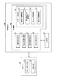
次に、図4を参照し、制御装置30の機能構成について説明する。図4は、制御装置30の機能構成の一例を示す図である。制御装置30は、記憶部32と、制御部36を備える。
Next, a functional configuration of the
制御部36は、制御装置30の全体を制御する。制御部36は、位置情報取得部41と、力検出情報取得部42と、傾斜情報取得部43と、加工装置制御部44と、ロボット制御部45を備える。制御部36が備えるこれらの機能部は、例えば、CPU31が、記憶部32に記憶された各種プログラムを実行することにより実現される。また、これらの機能部のうちの一部又は全部は、LSI(Large Scale Integration)やASIC(Application Specific Integrated Circuit)等のハードウェア機能部であってもよい。
The
位置情報取得部41は、記憶部32から各種位置情報を読み出す。
力検出情報取得部42は、力検出部22から力検出情報を取得する。
傾斜情報取得部43は、第1傾斜計測部21から傾斜情報を取得する。
加工装置制御部44は、加工装置40を制御する。この一例において、加工装置制御部44は、エンドエフェクターEに把持された物体Oが所定の加工位置へ移動した後、所定の照射時間だけレーザーLを照射する。
The position
The force detection
The tilt
The processing
ロボット制御部45は、給材工程制御部50と、傾斜調整工程制御部52と、加工工程制御部54と、除材工程制御部56を備える。
給材工程制御部50は、給材工程の作業をロボット20に行わせる。
傾斜調整工程制御部52は、傾斜調整工程の作業をロボット20に行わせる。
加工工程制御部54は、加工工程の作業をロボット20に行わせる。
除材工程制御部56は、除材工程の作業をロボット20に行わせる。
The
The material supply
The inclination adjustment
The processing
The removal
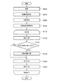
以下、図5を参照し、制御部36が行う処理について説明する。図5は、制御部36が行う処理の流れの一例を示すフローチャートである。
位置情報取得部41は、記憶部32から各種位置情報を取得する(ステップS100)。次に、ロボット制御部45は、ステップS100において取得した各種位置情報に含まれる物体位置情報が示す1以上の位置から1つずつ位置を選択し、選択した位置に配置されている物体O毎に、ステップS120からステップS150までの処理を繰り返し行う(ステップS110)。
Hereinafter, the processing performed by the
The position
給材工程制御部50は、給材工程の作業をロボット20に行わせる(ステップS120)。より具体的には、給材工程制御部50は、ステップS110において選択された位置に配置されている物体Oを把持(給材)する。次に、傾斜調整工程制御部52は、所定の条件が満たされているか否かを判定する(ステップS125)。所定の条件には、以下に示す3つの条件が含まれる。
The material supply
条件1)一度もステップS130において行われる傾斜調整工程の作業が行われていないこと
条件2)所定の時間が経過していること
条件3)ステップS120からステップS150までの処理が所定の回数以上行われていること
Condition 1) The work of the tilt adjustment step performed in step S130 has never been performed. Condition 2) A predetermined time has elapsed. Condition 3) The processing from step S120 to step S150 is performed a predetermined number of times or more. What is being done
所定の時間は、例えば、5分である。なお、所定の時間は、これに代えて、他の時間であってもよい。また、所定の回数は、例えば、5回である。なお、所定の回数は、これに代えて、他の回数であってもよい。また、所定の条件には、上記の条件のうちの条件1)及び条件2)のみが含まれる構成であってもよく、上記の条件のうちの条件1)及び条件3)のみが含まれる構成であってもよく、上記の条件1)〜条件3)に加えて他の条件が含まれる構成であってもよい。傾斜調整工程制御部52は、ステップS125において、上記の条件1)〜条件3)のうちの少なくとも1つが満たされている場合、所定の条件が満たされていると判定する。
The predetermined time is, for example, 5 minutes. Note that the predetermined time may be another time instead. The predetermined number of times is, for example, five. Note that the predetermined number may be another number instead. The predetermined condition may include only the condition 1) and the condition 2) of the above conditions, or may include only the condition 1) and the condition 3) of the above conditions. The configuration may include other conditions in addition to the above conditions 1) to 3). In step S125, when at least one of the above conditions 1) to 3) is satisfied, the tilt adjustment
所定の条件が満たされていると判定した場合(ステップS125−Yes)、傾斜調整工程制御部52は、傾斜調整工程の作業をロボット20に行わせる(ステップS130)。一方、所定の条件が満たされていないと傾斜調整工程制御部52が判定した場合(ステップS125−No)、加工工程制御部54は、加工工程の作業をロボット20に行わせる(ステップS140)。
When it is determined that the predetermined condition is satisfied (step S125-Yes), the tilt adjustment
ここで、ステップS130及びステップS140の処理について説明する。まず、図6〜図8を参照し、ステップS130の処理について説明する。
傾斜調整工程制御部52は、ステップS100において記憶部32から読み出した各種位置情報に含まれる基準面位置情報に基づいて、傾斜調整工程の作業において、エンドエフェクターEに把持された物体Oの作業面M3を基準面M1に接面させる。図6は、ロボット20がエンドエフェクターEに把持された物体Oを基準面M1に接面させようとしている最中の様子の一例を示す図である。この一例において、基準面位置情報が示す位置は、基準面M1の中心の位置である。なお、基準面位置情報が示す位置は、基準面M1の4つの角のうちの1つの角の位置等の基準面M1上の他の位置であってもよい。また、物体Oの位置は、この一例において、物体Oの重心の位置によって示される。
Here, the processing of step S130 and step S140 will be described. First, the process of step S130 will be described with reference to FIGS.
Based on the reference plane position information included in the various position information read out from the
図6に示したように、傾斜調整工程制御部52は、エンドエフェクターEを移動させることによってエンドエフェクターEに把持された物体Oの位置を、ロボット座標系におけるZ軸方向、すなわち重力方向に基準面M1から所定距離だけ離れた位置へ移動させる。傾斜調整工程制御部52は、エンドエフェクターEを移動させることによって物体Oを、図6に示した矢印TOの方向、すなわち当該重力方向とは反対の方向へ移動させて基準面M1へ近づける。そして、傾斜調整工程制御部52は、力検出情報取得部42が取得した力検出情報に基づく制御によって物体Oの作業面M3を、図7に示したように基準面M1に対して水平になるように基準面M1に接面させる。
As shown in FIG. 6, the tilt adjustment
図7は、ロボット20がエンドエフェクターEに把持された物体Oを基準面M1に接面させた直後の様子の一例を示す図である。ここで、物体Oの作業面M3が基準面M1に対して水平になるように基準面M1に接面した場合に、力検出部22から取得される力検出情報に含まれる力検出部22の出力値が所定の接面条件を満たす値となるように、力検出部22がソフトウェア又はハードウェアによって予め調整されている場合、傾斜調整工程制御部52は、力検出情報に含まれる3つの力を示す情報と、3つのモーメントを示す情報とに基づいて、物体Oの作業面M3を、基準面M1に対して水平になるように基準面M1に接面させることができる。このため、この一例における力検出部22は、このような調整が予め行われている。
FIG. 7 is a diagram illustrating an example of a state immediately after the
3つの力はそれぞれ、エンドエフェクターE又はエンドエフェクターEが把持した物体Oに加わった力のうちのX軸方向の力、Y軸方向の力、Z軸方向の力である。また、3つのモーメントはそれぞれ、エンドエフェクターE又はエンドエフェクターEが把持した物体Oに加わった力によってエンドエフェクターEを回転させようとする回転モーメントのうちのX軸周りに回転させようとする回転モーメント、Y軸周りに回転させようとする回転モーメント、Z軸周りに回転させようとする回転モーメントである。 The three forces are a force in the X-axis direction, a force in the Y-axis direction, and a force in the Z-axis direction among the forces applied to the end effector E or the object O gripped by the end effector E, respectively. In addition, the three moments are rotational moments for rotating the end effector E around the X-axis, among the rotational moments for rotating the end effector E by the force applied to the end effector E or the object O gripped by the end effector E. , A rotational moment about to rotate about the Y axis, and a rotational moment about to rotate about the Z axis.
傾斜調整工程制御部52は、これら3つの力それぞれの値と、3つのモーメントそれぞれの値とが前述の所定の接面条件を満たすようにエンドエフェクターEの姿勢を変化させながら物体Oの作業面M3を基準面M1に対して接面させる。所定の接面条件には、例えば、以下の2つの条件が含まれる。
The tilt adjustment
条件4)Z軸方向の力が所定値以上の力であり、X軸方向の力及びY軸方向の力がゼロであること
条件5)X軸周り、Y軸周り、Z軸周りそれぞれの回転モーメントが全てゼロであること
Condition 4) The force in the Z-axis direction is equal to or greater than a predetermined value, and the force in the X-axis direction and the force in the Y-axis direction are zero. Condition 5) Rotation around the X-axis, around the Y-axis, and around the Z-axis All moments are zero
なお、所定の接面条件には、上記の条件4)及び条件5)のいずれか一方又は両方に代えて、他の条件を含む構成であってもよく、上記の条件4)及び条件5に加えて他の条件を含む構成であってもよい。この一例では、傾斜調整工程制御部52は、上記の条件4)及び条件5)の両方が満たされた場合、所定の接面条件が満たされたと判定する。
It should be noted that the predetermined contact surface condition may be a configuration including other conditions instead of one or both of the above conditions 4) and 5). In addition, a configuration including other conditions may be employed. In this example, when both the above conditions 4) and 5) are satisfied, the inclination adjustment
そして、傾斜調整工程制御部52は、力検出情報取得部42が取得した力検出情報に含まれる3つの力を示す情報と、3つのモーメントを示す情報とが上記の所定の接面条件を満たした場合、物体Oの作業面M3が基準面M1に対して水平になるように基準面M1に接面したと判定する。物体Oの作業面M3が基準面M1に対して水平になるように基準面M1に接面した後、傾斜調整工程制御部52は、傾斜情報取得部43に第1傾斜計測部21から傾斜情報を取得させる。なお、この一例における傾斜調整工程において第1傾斜計測部21から傾斜情報を取得することは、第1角度を第1傾斜計により計測することの一例であるとともに、第2角度を第1傾斜計により計測することの一例である。
Then, the inclination adjustment
以上のように、傾斜調整工程制御部52は、傾斜調整工程の作業をロボット20に行わせる。なお、傾斜調整工程制御部52は、物体Oの作業面M3を基準面M1に対して接面させる構成に代えて、図8に示したように、エンドエフェクターEのハンド面M2を基準面M1に対して接面させる構成であってもよい。図8は、ロボット20が、物体Oを把持したエンドエフェクターEを基準面M1に接面させた直後の様子の一例を示す図である。
As described above, the tilt adjustment
この場合、エンドエフェクターEのハンド面M2が基準面M1に対して水平になるように基準面M1に接面した場合に、力検出部22から取得される力検出情報に含まれる力検出部22の出力値が上記の所定の接面条件を満たすように、力検出部22を予め調整しておく。これにより、傾斜調整工程制御部52は、力検出情報に含まれる3つの力を示す情報と、3つのモーメントを示す情報とに基づいて、エンドエフェクターEのハンド面M2を、基準面M1に対して水平になるように基準面M1に接面させることができる。エンドエフェクターEのハンド面M2が基準面M1に対して水平になるように基準面M1に接面した後、傾斜調整工程制御部52は、傾斜情報取得部43に第1傾斜計測部21から傾斜情報を取得させる。
In this case, when the hand surface M2 of the end effector E comes into contact with the reference surface M1 so as to be horizontal to the reference surface M1, the
傾斜調整工程制御部52が傾斜調整工程の作業をロボット20に行わせた後、加工工程制御部54は、ステップS125において所定の条件が満たされていないと傾斜調整工程制御部52が判定した場合と同様に、ステップS140における加工工程の作業をロボット20に行わせる。なお、ステップS125において所定の条件のうちの条件2又は条件3のいずれか一方又は両方が満たされていると判定した場合、傾斜情報取得部43が上記で説明したステップS130の処理を再度行うことは、第1角度の再計測の一例である。
After the tilt adjustment
以下、ステップS140の処理について説明する。ステップS140において、加工工程制御部54は、エンドエフェクターEを移動させることにより、傾斜情報取得部43から傾斜情報を取得しながら、ステップS130において傾斜情報取得部43が取得した傾斜情報が示す角度が変化しないように物体Oを、ステップS100において取得した各種位置情報に含まれる加工位置情報に基づいて所定の加工位置へ移動させる。物体Oの位置が所定の加工位置へ移動した後、加工装置制御部44は、加工装置40に所定の時間だけレーザーLを照射させる。レーザーLは、物体Oの作業面M3に所定の時間だけ照射される。そして、作業面M3は、レーザーLにより加工される。
Hereinafter, the process of step S140 will be described. In step S140, the machining
なお、ステップS125において所定の条件が満たされていないと傾斜調整工程制御部52が判定した場合、加工工程制御部54は、現在エンドエフェクターEが把持している物体Oの前にエンドエフェクターEが把持していた物体Oの作業面M3にレーザーLを照射する際に用いた傾斜情報(前回のステップS140の処理に用いた傾斜情報)を用いてステップS140の処理を行う。
When the inclination adjustment
ステップS140において加工装置40からのレーザーLの照射が終了した後、除材工程制御部56は、除材工程の作業をロボット20に行わせる(ステップS150)。より具体的には、除材工程制御部56は、ステップS100において取得した各種位置情報に含まれる除材位置情報に基づいて、作業面M3がレーザーLによって加工された後の物体Oを除材領域に除材する。
After the irradiation of the laser L from the
このように、制御部36は、ロボット20に所定の作業を行わせる。なお、ステップS125における判定は、ステップS130における傾斜調整工程の作業を、物体Oを加工するたびに毎回行わないようにするための判定である。このため、制御部36は、ロボット20に所定の作業を行わせる際、図5に示したフローチャートからステップS125を省略する構成であってもよい。
なお、上記においてハンド面M2に設けられた第1傾斜計測部21は、物体Oの作業面M3に設けられる構成であってもよい。この場合、第1傾斜計測部21は、制御装置30と無線によって通信可能に接続されていてもよい。
Thus, the
Note that, in the above description, the first
また、ロボットシステム1では、制御装置30が、物体Oの作業面M3を基準面M1に対して水平になるように基準面M1に接面させた状態において第1傾斜計測部21から傾斜情報を取得する構成に代えて、ハンド面M2から取り外された第1傾斜計測部21によって基準面M1の傾きが計測される構成であってもよい。この場合、第1傾斜計測部21は、無線通信によって制御装置30と通信可能に接続されていてもよい。第1傾斜計測部21がハンド面M2から取り外されてから基準面M1に設置された後、制御装置30は、基準面M1に設置された第1傾斜計測部21から傾斜情報を第2傾斜情報として取得する。その後、第1傾斜計測部21は、基準面M1から取り外されてハンド面M2に設置される。制御装置30は、ハンド面M2に設置された第1傾斜計測部21から傾斜情報を第1傾斜情報として取得し、取得した第1傾斜情報が示す角度が、取得した第2傾斜情報が示す角度に一致するようにエンドエフェクターEの姿勢を変化させる。このようにして、ロボットシステム1は、上記において説明した実施形態に係るロボットシステム1と同様の効果を得ることができる。
Further, in the
<実施形態の変形例1>
以下、図9〜図11を参照し、本発明の実施形態の変形例1について説明する。なお、実施形態の変形例1では、実施形態と同様な構成部に対して同じ符号を付して説明を省略する。図9は、本実施形態の変形例1に係るロボットシステム1aの一例を示す構成図である。ロボットシステム1aは、ロボット20と、制御装置30aを備える。実施形態の変形例1では、ロボットシステム1aは、上記で説明した実施形態と異なり、傾斜調整工程において作業面M3の傾きを、治具Jが有する基準面M1に代えて、図9に示した加工室Rの天井の面であって加工室Rの外側の基準面M4に対して水平にする。このため、図9に示したように、加工室R内には治具Jが設けられていない。
<
Hereinafter, a first modification of the embodiment of the present invention will be described with reference to FIGS. 9 to 11. In the first modification of the embodiment, the same components as those of the embodiment are denoted by the same reference numerals, and the description is omitted. FIG. 9 is a configuration diagram illustrating an example of a
基準面M4には、第2傾斜計測部60が設けられている。第2傾斜計測部60は、ロボット座標系におけるXY平面に対する基準面M4の傾きを計測するセンサーである。なお、第2傾斜計測部60は、当該XY平面に対する基準面M4の傾きを示す角度を計測する構成に代えて、他の面に対する基準面M4の傾きを示す角度を計測する構成であってもよい。基準面M4の傾きは、この一例において、当該XY平面のX軸方向とハンド面に設定された三次元局所座標系のX軸方向との間の傾きを示す角度と、当該XY平面のY軸方向と基準面M4に設定された三次元局所座標系のY軸方向との間の傾きを示す角度とによって表される。なお、基準面M4の傾きは、他の値によって表される構成であってもよい。
The second
第2傾斜計測部60は、計測した角度を出力値として含む傾斜情報を通信により制御装置30へ出力する。傾斜情報に含まれる基準面M4の傾きを示す1以上の角度は、第1角度の一例である。第2傾斜計測部60は、ケーブルによって制御装置30と通信可能に接続されている。ケーブルを介した有線通信は、例えば、イーサネット(登録商標)やUSB等の規格によって行われる。なお、第2傾斜計測部60は、Wi−Fi(登録商標)等の通信規格により行われる無線通信によって制御装置30と接続される構成であってもよい。
The second
図10は、制御装置30aの機能構成の一例を示す図である。制御装置30aは、記憶部32と、制御部36aを備える。
制御部36aは、位置情報取得部41と、力検出情報取得部42と、傾斜情報取得部43aと、加工装置制御部44と、ロボット制御部45aを備える。
傾斜情報取得部43aは、第1傾斜計測部21から傾斜情報を第1傾斜情報として取得する。また、傾斜情報取得部43aは、第2傾斜計測部60から傾斜情報を第2傾斜情報として取得する。
FIG. 10 is a diagram illustrating an example of a functional configuration of the
The
The inclination
ロボット制御部45aは、給材工程制御部50と、加工工程制御部54aと、除材工程制御部56を備える。
加工工程制御部54aは、傾斜情報取得部43が第1傾斜計測部21から取得した第1傾斜情報と、傾斜情報取得部43が第2傾斜計測部60から取得した第2傾斜情報とに基づいて、加工工程の作業をロボット20に行わせる。
The
The processing
以下、図11を参照し、制御部36aが行う処理について説明する。図11は、制御部36aが行う処理の流れの一例を示すフローチャートである。なお、図11に示したフローチャートのステップS100、ステップS110、ステップS120、ステップS150それぞれの処理は、図5に示したフローチャートのステップS100、ステップS110、ステップS120、ステップS150それぞれの処理と同様な処理のため、説明を省略する。
Hereinafter, the processing performed by the
ステップS120において給材工程の作業がロボット20により行われた後、加工工程制御部54aは、実施形態の変形例1に係る加工工程の作業をロボット20に行わせる(ステップS140a)。より具体的には、加工工程制御部54aは、傾斜情報取得部43に第2傾斜計測部60から第2傾斜情報を取得させる。
After the operation of the material supply step is performed by the
加工工程制御部54aは、傾斜情報取得部43から第1傾斜情報を取得しながら、第1傾斜情報が示す角度と、第2傾斜情報が示す角度である角度とが一致するように、すなわち基準面M4に対してハンド面M2が水平になるようにエンドエフェクターEのハンド面M2の姿勢を変化させる。
While acquiring the first inclination information from the inclination
この一例において、物体OがエンドエフェクターEに把持されている場合における作業面M3は、ハンド面M2に対して水平であるため、加工工程制御部54aは、基準面M4に対してハンド面M2が水平になるようにすることにより、基準面M4に対して作業面M3を水平にしている。物体OがエンドエフェクターEに把持されている場合における作業面M3が、ハンド面M2に対して水平ではない場合、ステップS140aにおいて加工工程制御部54aは、ハンド面M2に対する作業面M3の傾きを示す角度と、第1傾斜情報が示す角度と、第2傾斜情報が示す角度とに基づいて、基準面M4に対して作業面M3が水平となるようにエンドエフェクターEの姿勢を変化させる。
In this example, since the work surface M3 when the object O is gripped by the end effector E is horizontal with respect to the hand surface M2, the processing
基準面M4に対して作業面M3を水平にした後、加工工程制御部54aは、エンドエフェクターEを移動させることにより、傾斜情報取得部43から第1傾斜情報を取得しながら、ハンド面M2の姿勢が変化しないように物体Oを、ステップS100において取得した各種位置情報に含まれる加工位置情報に基づいて所定の加工位置へ移動させる。物体Oの位置が所定の加工位置へ移動した後、加工装置制御部44は、加工装置40に所定の時間だけレーザーLを照射させる。レーザーLは、物体Oの作業面M3に所定の時間だけ照射される。そして、作業面M3は、レーザーLにより加工される。
After leveling the work surface M3 with respect to the reference surface M4, the machining
以上のように、制御部36aは、傾斜調整工程において傾斜情報取得部43が取得した第1傾斜情報が示す角度と、傾斜情報取得部43が取得した第2傾斜情報が示す角度とに基づいて、作業面M3の傾きを基準面M4に対して水平にすることにより、加工工程の作業をロボット20に行わせる。これにより、ロボットシステム1aは、実施形態に係るロボットシステム1と同様の効果を得ることができる。
As described above, the
なお、実施形態の変形例1においてハンド面M2に設けられた第1傾斜計測部21は、物体Oの作業面M3に設けられる構成であってもよい。この場合、制御部36aは、傾斜調整工程において傾斜情報取得部43が取得した第1傾斜情報が示す角度と、傾斜情報取得部43が取得した第2傾斜情報が示す角度とに基づいて、ハンド面M2の傾きを基準面M4に対して水平にする。
Note that, in the first modification of the embodiment, the first
また、ロボットシステム1aでは、基準面M4の傾きが第2傾斜計測部60によって計測される構成に代えて、ハンド面M2から取り外された第1傾斜計測部21によって基準面M4の傾きが計測される構成であってもよい。この場合、第1傾斜計測部21は、無線通信によって制御装置30と通信可能に接続されていてもよい。第1傾斜計測部21がハンド面M2から取り外されてから基準面M4に設置された後、制御装置30は、基準面M4に設置された第1傾斜計測部21から傾斜情報を第2傾斜情報として取得する。その後、第1傾斜計測部21は、基準面M4から取り外されてハンド面M2に設置される。制御装置30は、ハンド面M2に設置された第1傾斜計測部21から傾斜情報を第1傾斜情報として取得し、取得した第1傾斜情報が示す角度が、取得した第2傾斜情報が示す角度に一致するようにエンドエフェクターEの姿勢を変化させる。このようにして、ロボットシステム1aは、実施形態に係るロボットシステム1と同様の効果を得ることができる。
In the
<実施形態の変形例2>
以下、図12〜図14を参照し、本発明の実施形態の変形例2について説明する。なお、実施形態の変形例2では、実施形態と同様な構成部に対して同じ符号を付して説明を省略する。図12は、ロボットシステム1bの一例を示す構成図である。ロボットシステム1bは、ロボット20bと、制御装置30bを備える。実施形態の変形例2では、ロボットシステム1bは、上記で説明した実施形態と同様に(実施形態の変形例1と異なり)、傾斜調整工程において作業面M3の傾きを、治具Jが有する基準面M1に対して水平にする。一方、ロボットシステム1bは、以下で説明する撮像部23を備えており、撮像部23が撮像した撮像画像に基づいてエンドエフェクターEの位置と、物体Oの位置とを検出する。ロボットシステム1bは、検出したエンドエフェクターEの位置と、物体Oの位置とに基づいて、給材工程の作業と、傾斜調整工程の作業と、加工工程の作業と、除材工程の作業をロボット20bに行わせる。
<Modification 2 of Embodiment>
Hereinafter, a second modification of the embodiment of the present invention will be described with reference to FIGS. In the second modification of the embodiment, the same components as those of the embodiment are denoted by the same reference numerals, and description thereof will be omitted. FIG. 12 is a configuration diagram illustrating an example of the
ロボット20bは、第1傾斜計測部21と、力検出部22と、撮像部23を備える。なお、ロボットシステム1は、ロボット20bと別体として撮像部23を備える構成であってもよい。また、図12では、図を簡略化するため、ロボット20bと作業面M3が別体として描いている。
The
撮像部23は、例えば、集光された光を電気信号に変換する撮像素子であるCCD(Charge Coupled Device)やCMOS(Complementary Metal Oxide Semiconductor)等を備えたステレオカメラである。撮像部23は、ケーブルによって制御装置30と通信可能に接続されている。ケーブルを介した有線通信は、例えば、イーサネット(登録商標)やUSB等の規格によって行われる。なお、撮像部23は、Wi−Fi(登録商標)等の通信規格により行われる無線通信によって制御装置30と接続される構成であってもよい。
The
撮像部23は、エンドエフェクターEが作業可能な領域を含む範囲を撮像範囲として撮像可能な位置に設置される。撮像部23は、撮像範囲の静止画像をステレオ撮像する構成であってもよく、撮像範囲の動画像をステレオ撮像する構成であってもよい。
The
図13は、制御装置30bの機能構成の一例を示す図である。制御装置30bは、記憶部32と、制御部36bを備える。
制御部36bは、位置情報取得部41と、力検出情報取得部42と、傾斜情報取得部43と、加工装置制御部44と、ロボット制御部45と、撮像制御部46と、画像取得部47と、位置検出部48を備える。
FIG. 13 is a diagram illustrating an example of a functional configuration of the
The
撮像制御部46は、撮像部23が撮像可能な撮像範囲を撮像部23にステレオ撮像させる。
画像取得部47は、撮像部23が撮像した撮像画像を撮像部23から取得する。
位置検出部48は、画像取得部47が取得した撮像画像に基づいて、エンドエフェクターEの位置と、物体Oの位置とを検出する。
The
The
The
以下、図14を参照し、制御部36bが行う処理について説明する。図14は、制御部36bが行う処理の流れの一例を示すフローチャートである。なお、図14に示したフローチャートのステップS100〜ステップS150までの処理は、図5に示したフローチャートのステップS100〜ステップS150までの処理と同様な処理のため、説明を省略する。
Hereinafter, the processing performed by the
撮像制御部46は、撮像部23が撮像可能な撮像範囲を撮像部23に撮像させる(ステップS200)。次に、画像取得部47は、ステップS200において撮像部23が撮像した撮像画像を撮像部23から取得する(ステップS210)。次に、位置検出部48は、ステップS210において画像取得部47が取得した撮像画像に基づいて、エンドエフェクターEの位置を検出する。また、位置検出部48は、当該撮像画像に基づいて、図示しない給材領域に配置された1以上の物体Oそれぞれの位置を検出する(ステップS220)。
The
ここで、ステップS220の処理について説明する。実施形態の変形例2において、エンドエフェクターEと、1以上の物体Oのそれぞれとには、それぞれの位置を示すマーカーが設けられている。位置検出部48は、撮像画像から当該マーカーを検出し、検出したマーカーが示す位置を検出する。
Here, the process of step S220 will be described. In the modified example 2 of the embodiment, markers indicating the respective positions are provided on the end effector E and each of the one or more objects O. The
なお、このように、実施形態の変形例2では、エンドエフェクターEの位置と、1以上の物体Oのそれぞれの位置とが、位置検出部48により検出されるため、各種位置情報は、前述した物体位置情報を含まない構成であってもよい。また、位置検出部48は、撮像画像に基づいて、エンドエフェクターEと、1以上の物体Oそれぞれの位置を検出する構成に代えて、エンドエフェクターEと、1以上の物体Oそれぞれの位置と、基準面M1の位置と、図示しない除材領域の位置と、所定の加工位置とのうちの一部又は全部を検出する構成であってもよい。また、位置検出部48は、エンドエフェクターEの位置と、1以上の物体Oのそれぞれの位置とを、パターンマッチング等の他の方法によって検出する構成であってもよい。
As described above, in the second modification of the embodiment, since the position of the end effector E and the respective positions of the one or more objects O are detected by the
以上のように、制御部36bは、撮像部23が撮像した撮像画像からエンドエフェクターEの位置と、1以上の物体Oそれぞれの位置を検出する。そして、制御部36bは、検出したこれらの位置に基づいて、給材工程の作業と、傾斜調整工程の作業と、加工工程の作業と、除材工程の作業とをロボット20bに行わせる。これにより、ロボットシステム1bは、実施形態に係るロボットシステム1と同様の効果を得ることができる。
As described above, the
なお、実施形態の変形例2のようにロボットシステム1bが撮像部23を備える場合、制御部36aは、画像取得部47が取得した撮像画像に基づいて、エンドエフェクターEが物体Oを把持している際にエンドエフェクターEと物体Oの相対的な位置関係がずれたことを検出する構成であってもよい。より具体的には、制御部36aは、画像取得部47が取得した撮像画像に基づいて、エンドエフェクターEが物体Oを把持している際にエンドエフェクターEのハンド面M2に対して物体Oの作業面M3が水平ではなくなったことを検出する構成であってもよい。この場合、ロボット制御部45aは、エンドエフェクターEに物体Oを把持し直させることにより、エンドエフェクターEのハンド面M2に対して物体Oの作業面M3を水平にする。
When the
以上のように、ロボットシステム1(又は、ロボットシステム1aやロボットシステム1b)は、エンドエフェクターEに設けられた第1傾斜計測部21から取得される傾斜情報を用いて加工工程の作業をロボット20(又はロボット20b)に行わせる。このため、エンドエフェクターEに第1傾斜計測部21を設ける際、エンドエフェクターEのハンド面M2と、第1傾斜計測部のハンド面M2に設置される側の面である傾斜計面との位置関係が基準の位置関係からずれていた場合、ロボットシステム1(又はロボットシステム1aやロボットシステム1b)は、加工工程の作業をロボット20(又はロボット20b)に行わせる際に、第1傾斜計測部21から取得される傾斜情報を、ハンド面M2と傾斜計面との位置関係が基準の位置関係である場合において取得される傾斜情報への補正を行う必要がある。以下では、当該補正を行う処理について説明する。
As described above, the robot system 1 (or the
<ハンド面M2と傾斜計面との位置関係に応じた傾斜情報の補正方法>
以下、図15を参照し、ハンド面M2と傾斜計面との位置関係に応じた傾斜情報の補正方法について説明する。図15は、ハンド面M2と傾斜計面との位置関係に応じた傾斜情報の補正方法を説明するための図である。図15には、ハンド面M2の姿勢を示す局所座標系の3つの座標軸(X軸Hx、Y軸Hy、Z軸Hz)と、傾斜計面の姿勢を示す局所座標系の3つの座標軸(X軸Sx、Y軸Sy、Z軸Sz)とが示されている。前述の基準の位置関係は、ハンド面M2の姿勢を示す局所座標系と、傾斜計面の姿勢を示す局所座標系とが一致する場合におけるハンド面M2と傾斜計面との位置関係のことである。また、図15に示した例では、これらの局所座標系の原点及びZ軸方向は、一致している。しかし、当該例では、これらの局所座標系のX軸方向及びY軸方向はそれぞれ、角度αだけずれている。すなわち、図15に示した例は、ハンド面M2と傾斜計面との位置関係が基準の位置関係からずれている場合の一例である。
<Correction method of inclination information according to the positional relationship between hand surface M2 and inclinometer surface>
Hereinafter, a method of correcting tilt information according to the positional relationship between the hand surface M2 and the inclinometer surface will be described with reference to FIG. FIG. 15 is a diagram for explaining a method of correcting the inclination information according to the positional relationship between the hand surface M2 and the inclinometer surface. FIG. 15 shows three coordinate axes (X axis Hx, Y axis Hy, and Z axis Hz) of the local coordinate system indicating the attitude of the hand surface M2 and three coordinate axes (X The axis Sx, the Y axis Sy, and the Z axis Sz) are shown. The above-described reference positional relationship refers to the positional relationship between the hand surface M2 and the inclinometer surface when the local coordinate system indicating the attitude of the hand surface M2 matches the local coordinate system indicating the attitude of the inclinometer surface. is there. Further, in the example shown in FIG. 15, the origin and the Z-axis direction of these local coordinate systems match. However, in this example, the X-axis direction and the Y-axis direction of these local coordinate systems are each shifted by the angle α. That is, the example shown in FIG. 15 is an example in which the positional relationship between the hand surface M2 and the inclinometer surface deviates from the reference positional relationship.
このような場合、例えば、ロボット制御部45は、現在のハンド面M2の姿勢を示す局所座標系のX軸方向をX軸の傾きの基準(ゼロ点)とし、当該局所座標系のY軸方向をY軸の傾きの基準(ゼロ)とする。そして、ロボット制御部45は、ハンド面M2の姿勢を示す局所座標系のX軸周りにエンドエフェクターEを角度βだけ回転させる。この場合、第1傾斜計測部21から取得される傾斜情報は、傾斜計面のロボット座標系のXY平面に対する傾きを示す。
In such a case, for example, the
このため、当該傾斜情報を、以下に示した式(1)及び式(2)を用いて、ハンド面M2のロボット座標系のXY平面に対する傾きへ補正する。傾斜計面の姿勢を示す局所座標系のY軸の当該XY平面に対する傾きを示す角度を角度γ1とし、当該局所座標系のX軸の当該XY平面に対する傾きを示す角度を角度γ2とすると、角度γ1及び角度γ2と、角度α及び角度βとの関係は、幾何学に基づいて以下に示した式(1)及び式(2)として表される。 For this reason, the inclination information is corrected to the inclination of the hand surface M2 with respect to the XY plane of the robot coordinate system using Expressions (1) and (2) shown below. If the angle indicating the inclination of the Y axis of the local coordinate system indicating the attitude of the inclinometer plane with respect to the XY plane is defined as an angle γ1, and the angle indicating the inclination of the X axis of the local coordinate system relative to the XY plane is defined as an angle γ2, the angle The relationship between γ1 and the angle γ2 and the angle α and the angle β are expressed as the following equations (1) and (2) based on the geometry.
sin(γ1)=cos(α)×sin(β) ・・・(1) sin (γ1) = cos (α) × sin (β) (1)
sin(γ2)=cos(90°−α)×sin(β)=sin(α)×sin(β) ・・・(2) sin (γ2) = cos (90 ° −α) × sin (β) = sin (α) × sin (β) (2)
ロボット制御部45は、これらの式に基づいて、ハンド面M2のロボット座標系のXY平面に対する傾きへ補正する。すなわち、ロボット制御部45は、ハンド面M2と、傾斜計面との基準の位置関係からのずれを補正する。これにより、ロボットシステム1は、ハンド面M2に対する第1傾斜計測部21の設置を容易にすることができる。なお、傾斜計面は、傾斜計の所定面の一例である。
The
以上説明したように、実施形態におけるロボットシステム1(又はロボットシステム1aやロボットシステム1b)は、基準面(例えば、基準面M1や基準面M4)の第1角度(この一例において、基準面M1の傾きを示す角度)と、第1傾斜計により計測された第2角度(この一例において、ハンド面M2又は作業面M3の傾きを示す角度)とに基づいてアームを動作させる。これにより、ロボットシステム1は、基準面と第2角度とに応じた動作によって物体(この一例において、物体O)を移動させることができる。
As described above, the robot system 1 (or the
また、ロボットシステム1は、第1角度を第1傾斜計(この一例において、第1傾斜計測部21)により計測する。これにより、ロボットシステム1は、第1傾斜計により計測された第1角度及び第2角度と基準面と基づく動作によって物体を移動させることができる。
In addition, the
また、ロボットシステム1は、基準面に物体の所定面(この一例において、作業面M3)又は把持部(この一例において、エンドエフェクターE)の所定面(この一例において、ハンド面M2)を接面させた状態において第1角度を第1傾斜計により計測する。これにより、ロボットシステム1は、基準面に物体の所定面又は把持部の所定面を接面させた状態において第1傾斜計により計測された第1角度と第2角度に基づく動作によって物体を移動させることができる。
In addition, the
また、ロボットシステム1は、力検出器(この一例において、力検出部22)の出力(この一例において、力検出情報)に基づいて、基準面に物体の所定面又は把持部の所定面を接面させる。これにより、ロボットシステム1は、力検出器の出力に基づいて物体の所定面又は把持部の所定面が基準面に接面させた状態を用いて、物体を移動させることができる。
In addition, the
また、ロボットシステム1aは、第1角度を、第1傾斜計とは異なる第2傾斜計(この一例において、第2傾斜計測部60)により計測する。これにより、ロボットシステム1aは、第2傾斜計により計測された第1角度と、第1傾斜計により計測された第2角度とに基づいて、基準面に応じた動作によって物体を移動させることができる。
Further, the
また、ロボットシステム1は、アームの少なくとも一部(この一例において、エンドエフェクターE)を、基準面に対して水平に移動させる。これにより、ロボットシステム1は、物体を基準面に対して水平に移動させることができる。
Further, the
また、ロボットシステム1は、基準面を用いて計測された第1角度と、加工装置(この一例において、加工装置40)により加工されるワーク(この一例において、物体O)又は把持部に設けられた第1傾斜計により計測された第2角度とに基づいてアームを動作させる。これにより、ロボットシステム1は、基準面に応じた動作によって加工装置により加工されるワークを移動させることができる。
Further, the
また、ロボットシステム1bは、撮像部(この一例において、撮像部23)により撮像された撮像画像に基づいて、把持部と物体との位置関係を変更する。これにより、ロボットシステム1bは、把持部と物体との位置関係がずれてしまった場合であっても、ずれる前の位置関係に戻すことができる。
Further, the
また、ロボットシステム1は、所定の条件が満たされた場合、第1角度を再計測する。これにより、ロボットシステム1は、第1角度がずれている可能性が高い場合に、第1角度を再計測することができる。
In addition, when a predetermined condition is satisfied, the
また、ロボットシステム1は、物体の所定面又は把持部の所定面と、第1傾斜計の所定面との基準の位置関係からのずれを補正する。これにより、ロボットシステム1は、補正した当該位置関係に基づいて、基準面に応じた動作によって物体を移動させることができる。
Further, the
以上、この発明の実施形態を、図面を参照して詳述してきたが、具体的な構成はこの実施形態に限られるものではなく、この発明の要旨を逸脱しない限り、変更、置換、削除等されてもよい。 The embodiment of the present invention has been described in detail with reference to the drawings. However, the specific configuration is not limited to this embodiment, and may be changed, replaced, deleted, or the like without departing from the gist of the present invention. May be done.
また、以上に説明した装置(例えば、制御装置30)における任意の構成部の機能を実現するためのプログラムを、コンピューター読み取り可能な記録媒体に記録し、そのプログラムをコンピューターシステムに読み込ませて実行するようにしてもよい。なお、ここでいう「コンピューターシステム」とは、OS(Operating System)や周辺機器等のハードウェアを含むものとする。また、「コンピューター読み取り可能な記録媒体」とは、フレキシブルディスク、光磁気ディスク、ROM、CD(Compact Disk)−ROM等の可搬媒体、コンピューターシステムに内蔵されるハードディスク等の記憶装置のことをいう。さらに「コンピューター読み取り可能な記録媒体」とは、インターネット等のネットワークや電話回線等の通信回線を介してプログラムが送信された場合のサーバーやクライアントとなるコンピューターシステム内部の揮発性メモリー(RAM)のように、一定時間プログラムを保持しているものも含むものとする。 Further, a program for realizing the function of an arbitrary component in the above-described device (for example, the control device 30) is recorded on a computer-readable recording medium, and the program is read and executed by a computer system. You may do so. Here, the “computer system” includes an OS (Operating System) and hardware such as peripheral devices. The “computer-readable recording medium” refers to a portable medium such as a flexible disk, a magneto-optical disk, a ROM, a CD (Compact Disk) -ROM, and a storage device such as a hard disk built in a computer system. . Further, the “computer-readable recording medium” refers to a volatile memory (RAM) inside a computer system that is a server or a client when a program is transmitted through a network such as the Internet or a communication line such as a telephone line. And those holding programs for a certain period of time.
また、上記のプログラムは、このプログラムを記憶装置等に格納したコンピューターシステムから、伝送媒体を介して、あるいは、伝送媒体中の伝送波により他のコンピューターシステムに伝送されてもよい。ここで、プログラムを伝送する「伝送媒体」は、インターネット等のネットワーク(通信網)や電話回線等の通信回線(通信線)のように情報を伝送する機能を有する媒体のことをいう。
また、上記のプログラムは、前述した機能の一部を実現するためのものであってもよい。さらに、上記のプログラムは、前述した機能をコンピューターシステムにすでに記録されているプログラムとの組み合わせで実現できるもの、いわゆる差分ファイル(差分プログラム)であってもよい。
Further, the above program may be transmitted from a computer system storing the program in a storage device or the like to another computer system via a transmission medium or by a transmission wave in the transmission medium. Here, the "transmission medium" for transmitting a program refers to a medium having a function of transmitting information, such as a network (communication network) such as the Internet or a communication line (communication line) such as a telephone line.
Further, the above program may be a program for realizing a part of the functions described above. Furthermore, the above-mentioned program may be a program that can realize the above-described functions in combination with a program already recorded in the computer system, that is, a so-called difference file (difference program).
1、1a、1b ロボットシステム、20、20b ロボット、21 第1傾斜計測部、22 力検出部、23 撮像部、30、30a、30b 制御装置、31 CPU、32 記憶部、33 入力受付部、34 通信部、35 表示部、36、36a、36b 制御部、40 加工装置、41 位置情報取得部、42 力検出情報取得部、43 傾斜情報取得部、44 加工装置制御部、45、45a ロボット制御部、46 撮像制御部、47 画像取得部、48 位置検出部、50 給材工程制御部、52 傾斜調整工程制御部、54、54a 加工工程制御部、56 除材工程制御部、60 第2傾斜計測部、211 第1通信方式変換部、221 第2通信方式変換部 1, 1a, 1b robot system, 20, 20b robot, 21 first tilt measuring section, 22 force detecting section, 23 imaging section, 30, 30a, 30b control device, 31 CPU, 32 storage section, 33 input receiving section, 34 Communication unit, 35 display unit, 36, 36a, 36b control unit, 40 processing device, 41 position information acquisition unit, 42 force detection information acquisition unit, 43 inclination information acquisition unit, 44 processing device control unit, 45, 45a robot control unit , 46 imaging control unit, 47 image acquisition unit, 48 position detection unit, 50 material supply process control unit, 52 tilt adjustment process control unit, 54, 54a processing process control unit, 56 material removal process control unit, 60 second tilt measurement Unit, 211 first communication system conversion unit, 221 second communication system conversion unit
Claims (10)
前記ロボットの動作を制御する制御装置と、
前記アームに設けられ、物体を把持する把持部と、
前記把持部又は前記物体に設けられる第1傾斜計と、
第1所定面に対して第1角度の傾きを有する基準面と、を備え、
前記把持部は、第2所定面を備え、
前記物体は、第3所定面を備え、
前記第1傾斜計は、前記第1所定面に対する前記第2所定面の傾き、又は前記第1所定面に対する前記第3所定面の傾き、である第2角度を計測し、
前記制御装置は、前記第1角度と前記第2角度とに基づいて前記アームを動作させる、
ロボットシステム。 A robot with an arm,
A control device for controlling the operation of the robot,
A grip portion provided on the arm, for gripping an object;
A first inclinometer provided on the gripper or the object,
A reference plane having a first angle of inclination with respect to the first predetermined plane;
The grip has a second predetermined surface,
The object has a third predetermined surface,
The first inclinometer measures a second angle that is the inclination of the second predetermined surface with respect to the first predetermined surface, or the inclination of the third predetermined surface with respect to the first predetermined surface,
The control device operates the arm based on the first angle and the second angle,
Robot system.
請求項1に記載のロボットシステム。 The first inclinometer measures the first angle,
The robot system according to claim 1.
請求項2に記載のロボットシステム。 In a state where the second predetermined surface or the third predetermined surface is in contact with the reference surface, the first inclinometer measures the first angle,
The robot system according to claim 2.
前記制御装置は、前記力検出器の出力に基づいて、前記基準面に前記第2所定面又は前記第3所定面を接面させる、
請求項3に記載のロボットシステム。 The robot system includes a force detector provided on the arm and detecting a force,
The control device causes the second predetermined surface or the third predetermined surface to contact the reference surface based on an output of the force detector,
The robot system according to claim 3.
請求項1に記載のロボットシステム。 The robot system includes a second inclinometer that measures the first angle,
The robot system according to claim 1.
請求項1から5のうちいずれか一項に記載のロボットシステム。 The control device moves at least a part of the arm in parallel with the reference plane,
The robot system according to any one of claims 1 to 5.
前記物体は、前記加工装置により加工されるワークである、
請求項1から6のうちいずれか一項に記載のロボットシステム。 The robot system includes a processing device provided on a plane parallel to the reference plane,
The object is a workpiece processed by the processing device,
The robot system according to any one of claims 1 to 6.
前記撮像部により撮像された撮像画像に基づいて、前記把持部と前記物体との位置関係を変更する、
請求項1から7のうちいずれか一項に記載のロボットシステム。 The robot system includes an imaging unit,
Based on a captured image captured by the imaging unit, change the positional relationship between the grip unit and the object,
The robot system according to claim 1.
前記アームに設けられ、第2所定面を有する把持部又は前記把持部により把持され、第3所定面を有する物体には、第1傾斜計が設けられ、
第1所定面に対する基準面の傾きである第1角度と、前記第1所定面に対する前記第2所定面の傾き又は前記所定第1所定面に対する前記第3所定面の傾きである第2角度と、
に基づいて前記アームを動作させ、
前記第2角度は、前記第1傾斜計により計測される、
ロボット。 Equipped with an arm,
A first inclinometer is provided on the arm, the object having a third predetermined surface, which is gripped by a gripper having the second predetermined surface or the gripper, and having a third predetermined surface,
A first angle that is the inclination of the reference plane with respect to the first predetermined plane, and a second angle that is the inclination of the second predetermined plane with respect to the first predetermined plane or the inclination of the third predetermined plane with respect to the predetermined first predetermined plane. ,
Operating the arm based on
The second angle is measured by the first inclinometer.
robot.
制御装置。 Controlling the operation of the robot according to claim 9;
Control device.
Priority Applications (3)
| Application Number | Priority Date | Filing Date | Title |
|---|---|---|---|
| JP2015170162A JP6665450B2 (en) | 2015-08-31 | 2015-08-31 | Robot, control device, and robot system |
| US15/244,106 US10369703B2 (en) | 2015-08-31 | 2016-08-23 | Robot, control device, and robot system |
| CN201610738827.1A CN106476015B (en) | 2015-08-31 | 2016-08-26 | Robot, control device, and robot system |
Applications Claiming Priority (1)
| Application Number | Priority Date | Filing Date | Title |
|---|---|---|---|
| JP2015170162A JP6665450B2 (en) | 2015-08-31 | 2015-08-31 | Robot, control device, and robot system |
Publications (3)
| Publication Number | Publication Date |
|---|---|
| JP2017047479A JP2017047479A (en) | 2017-03-09 |
| JP2017047479A5 JP2017047479A5 (en) | 2018-09-06 |
| JP6665450B2 true JP6665450B2 (en) | 2020-03-13 |
Family
ID=58097560
Family Applications (1)
| Application Number | Title | Priority Date | Filing Date |
|---|---|---|---|
| JP2015170162A Active JP6665450B2 (en) | 2015-08-31 | 2015-08-31 | Robot, control device, and robot system |
Country Status (3)
| Country | Link |
|---|---|
| US (1) | US10369703B2 (en) |
| JP (1) | JP6665450B2 (en) |
| CN (1) | CN106476015B (en) |
Cited By (1)
| Publication number | Priority date | Publication date | Assignee | Title |
|---|---|---|---|---|
| WO2024058574A1 (en) * | 2022-09-15 | 2024-03-21 | 삼성전자주식회사 | Serving robot and control method thereof |
Families Citing this family (3)
| Publication number | Priority date | Publication date | Assignee | Title |
|---|---|---|---|---|
| JP6472472B2 (en) * | 2017-03-08 | 2019-02-20 | 本田技研工業株式会社 | Position and orientation adjustment method |
| JP6756761B2 (en) | 2018-03-27 | 2020-09-16 | ファナック株式会社 | Production method and production system using robots |
| JP7348965B2 (en) * | 2020-01-29 | 2023-09-21 | 株式会社Fuji | Information processing device and information processing method |
Family Cites Families (26)
| Publication number | Priority date | Publication date | Assignee | Title |
|---|---|---|---|---|
| US4718023A (en) * | 1984-11-27 | 1988-01-05 | Photo Acoustic Technology, Inc. | Ultrasonic apparatus for positioning a robot hand |
| JPS62199383A (en) * | 1986-02-26 | 1987-09-03 | 富士通株式会社 | Control system of robot |
| JPS62254206A (en) * | 1986-04-28 | 1987-11-06 | Fuji Electric Co Ltd | Deciding device for plane direction |
| JPS63180492A (en) * | 1987-01-21 | 1988-07-25 | 三菱電機株式会社 | Industrial robot device |
| US5239855A (en) * | 1991-07-12 | 1993-08-31 | Hewlett-Packard Company | Positional calibration of robotic arm joints relative to the gravity vector |
| JPH06131032A (en) * | 1992-04-14 | 1994-05-13 | Hitachi Ltd | Robot device and teaching method for robot device |
| US6057695A (en) * | 1993-09-15 | 2000-05-02 | Intest Corporation | Method and apparatus for automated docking of a test head to a device handler |
| JPH08320717A (en) * | 1995-05-26 | 1996-12-03 | Nippon Steel Corp | Method for correcting attitude and position of industrial robot |
| JPH09258814A (en) | 1996-03-22 | 1997-10-03 | Kayaba Ind Co Ltd | Device and method for controlling position of assembling robot |
| JPH11165287A (en) * | 1997-12-08 | 1999-06-22 | Yukio Saito | Position detection device, position control device and robot control device |
| JP3702257B2 (en) * | 2002-08-23 | 2005-10-05 | ファナック株式会社 | Robot handling device |
| US6822412B1 (en) * | 2003-06-11 | 2004-11-23 | Zhongxue Gan | Method for calibrating and programming of a robot application |
| JP4271249B2 (en) * | 2007-06-14 | 2009-06-03 | ファナック株式会社 | Mating device |
| JP5200777B2 (en) * | 2008-09-04 | 2013-06-05 | 株式会社Ihi | Robot apparatus teaching method and robot apparatus teaching jig |
| EP2255930A1 (en) * | 2009-05-27 | 2010-12-01 | Leica Geosystems AG | Method and system for extremely precise positioning of at least one object in the end position in space |
| KR100986669B1 (en) * | 2009-06-08 | 2010-10-08 | (주)이지로보틱스 | A device and method for calibrating a robot |
| GB2473191B (en) * | 2009-09-02 | 2013-11-27 | Univ Sheffield | Wall Mounted Robotic Arm and Position Sensing System |
| CN102294695A (en) * | 2010-06-25 | 2011-12-28 | 鸿富锦精密工业(深圳)有限公司 | Robot calibration method and calibration system |
| US9904271B2 (en) * | 2011-11-16 | 2018-02-27 | Nissan Motor Co., Ltd. | Manufacturing method and manufacturing device for manufacturing a joined piece |
| CN102764166B (en) * | 2012-07-20 | 2014-09-03 | 山东科技大学 | Upper prosthetic hand pose self-balancing control system and working method thereof |
| JP5678979B2 (en) * | 2013-03-15 | 2015-03-04 | 株式会社安川電機 | Robot system, calibration method, and workpiece manufacturing method |
| JP2014205198A (en) * | 2013-04-10 | 2014-10-30 | セイコーエプソン株式会社 | Robot, robot control device, and robot system |
| ES2522921B2 (en) * | 2013-05-17 | 2015-07-30 | Loxin 2002, S.L. | Head and automatic machining procedure with vision |
| CN104608128A (en) * | 2013-11-01 | 2015-05-13 | 精工爱普生株式会社 | Robot, control device, robot system and robot control method |
| JP5845311B2 (en) * | 2014-04-30 | 2016-01-20 | ファナック株式会社 | Control device for flexible control of robots |
| CN104842362B (en) * | 2015-06-18 | 2017-04-05 | 厦门理工学院 | A kind of method of robot crawl material bag and robotic gripping device |
-
2015
- 2015-08-31 JP JP2015170162A patent/JP6665450B2/en active Active
-
2016
- 2016-08-23 US US15/244,106 patent/US10369703B2/en active Active
- 2016-08-26 CN CN201610738827.1A patent/CN106476015B/en active Active
Cited By (1)
| Publication number | Priority date | Publication date | Assignee | Title |
|---|---|---|---|---|
| WO2024058574A1 (en) * | 2022-09-15 | 2024-03-21 | 삼성전자주식회사 | Serving robot and control method thereof |
Also Published As
| Publication number | Publication date |
|---|---|
| CN106476015A (en) | 2017-03-08 |
| JP2017047479A (en) | 2017-03-09 |
| CN106476015B (en) | 2021-06-22 |
| US20170057093A1 (en) | 2017-03-02 |
| US10369703B2 (en) | 2019-08-06 |
Similar Documents
| Publication | Publication Date | Title |
|---|---|---|
| US10589424B2 (en) | Robot control device, robot, and robot system | |
| JP6380828B2 (en) | Robot, robot system, control device, and control method | |
| US20160184996A1 (en) | Robot, robot system, control apparatus, and control method | |
| CN107414842B (en) | Control device, robot, and robot system | |
| US20170277167A1 (en) | Robot system, robot control device, and robot | |
| JP6648469B2 (en) | Robot system and robot controller | |
| JP6665450B2 (en) | Robot, control device, and robot system | |
| US20170203434A1 (en) | Robot and robot system | |
| JP6661925B2 (en) | Control devices, robots and robot systems | |
| JP2018111155A (en) | Robot control device, robot and robot system | |
| JP2018034242A (en) | Robot control device, robot, and robot system | |
| JP6897396B2 (en) | Control devices, robot systems and control methods | |
| US20160306340A1 (en) | Robot and control device | |
| US20180215044A1 (en) | Image processing device, robot control device, and robot | |
| JP2018015854A (en) | Robot, robot control device, robot system, and control method | |
| JP2021133470A (en) | Control method of robot and robot system | |
| JP2015182212A (en) | Robot system, robot, control device, and control method | |
| CN111618845B (en) | Robot system | |
| JP2016120530A (en) | Robot and robot calibration system | |
| JP2016120558A (en) | Robot and robot system | |
| JP6578671B2 (en) | ROBOT, ROBOT CONTROL METHOD, AND ROBOT CONTROL DEVICE | |
| JP2019042902A (en) | Imaging method and robot system | |
| JP2017052073A (en) | Robot system, robot and robot control device | |
| JP2018001321A (en) | Robot, robot control device and robot system | |
| JP2016120557A (en) | Robot and robot calibration system |
Legal Events
| Date | Code | Title | Description |
|---|---|---|---|
| A521 | Written amendment |
Free format text: JAPANESE INTERMEDIATE CODE: A523 Effective date: 20180727 |
|
| A621 | Written request for application examination |
Free format text: JAPANESE INTERMEDIATE CODE: A621 Effective date: 20180727 |
|
| RD05 | Notification of revocation of power of attorney |
Free format text: JAPANESE INTERMEDIATE CODE: A7425 Effective date: 20180906 |
|
| RD03 | Notification of appointment of power of attorney |
Free format text: JAPANESE INTERMEDIATE CODE: A7423 Effective date: 20181116 |
|
| A977 | Report on retrieval |
Free format text: JAPANESE INTERMEDIATE CODE: A971007 Effective date: 20190726 |
|
| A131 | Notification of reasons for refusal |
Free format text: JAPANESE INTERMEDIATE CODE: A131 Effective date: 20190806 |
|
| A521 | Written amendment |
Free format text: JAPANESE INTERMEDIATE CODE: A523 Effective date: 20190930 |
|
| TRDD | Decision of grant or rejection written | ||
| A01 | Written decision to grant a patent or to grant a registration (utility model) |
Free format text: JAPANESE INTERMEDIATE CODE: A01 Effective date: 20200121 |
|
| A61 | First payment of annual fees (during grant procedure) |
Free format text: JAPANESE INTERMEDIATE CODE: A61 Effective date: 20200203 |
|
| R150 | Certificate of patent or registration of utility model |
Ref document number: 6665450 Country of ref document: JP Free format text: JAPANESE INTERMEDIATE CODE: R150 |