JP2017169658A - Medical tube manufacturing method and manufacturing apparatus - Google Patents
Medical tube manufacturing method and manufacturing apparatus Download PDFInfo
- Publication number
- JP2017169658A JP2017169658A JP2016056612A JP2016056612A JP2017169658A JP 2017169658 A JP2017169658 A JP 2017169658A JP 2016056612 A JP2016056612 A JP 2016056612A JP 2016056612 A JP2016056612 A JP 2016056612A JP 2017169658 A JP2017169658 A JP 2017169658A
- Authority
- JP
- Japan
- Prior art keywords
- tube
- manufacturing
- mold
- pressing
- convex structure
- Prior art date
- Legal status (The legal status is an assumption and is not a legal conclusion. Google has not performed a legal analysis and makes no representation as to the accuracy of the status listed.)
- Granted
Links
- 238000004519 manufacturing process Methods 0.000 title claims abstract description 78
- 238000003825 pressing Methods 0.000 claims abstract description 67
- 238000000034 method Methods 0.000 claims abstract description 36
- 230000008569 process Effects 0.000 claims abstract description 16
- 238000003780 insertion Methods 0.000 claims abstract description 5
- 230000037431 insertion Effects 0.000 claims abstract description 5
- 238000010438 heat treatment Methods 0.000 claims description 22
- 238000001816 cooling Methods 0.000 claims description 20
- YCKRFDGAMUMZLT-UHFFFAOYSA-N Fluorine atom Chemical compound [F] YCKRFDGAMUMZLT-UHFFFAOYSA-N 0.000 claims description 19
- 229910052731 fluorine Inorganic materials 0.000 claims description 19
- 239000011737 fluorine Substances 0.000 claims description 19
- 239000011248 coating agent Substances 0.000 claims description 13
- 239000002184 metal Substances 0.000 claims description 12
- 238000000576 coating method Methods 0.000 claims description 5
- 238000007664 blowing Methods 0.000 claims 1
- 239000007788 liquid Substances 0.000 abstract description 5
- 239000012620 biological material Substances 0.000 abstract description 2
- 210000003437 trachea Anatomy 0.000 description 19
- 238000011156 evaluation Methods 0.000 description 13
- 238000004891 communication Methods 0.000 description 12
- 230000002093 peripheral effect Effects 0.000 description 12
- 239000012530 fluid Substances 0.000 description 9
- 238000012546 transfer Methods 0.000 description 8
- 239000000126 substance Substances 0.000 description 7
- 206010036790 Productive cough Diseases 0.000 description 6
- -1 polytetrafluoroethylene Polymers 0.000 description 6
- 210000003802 sputum Anatomy 0.000 description 6
- 208000024794 sputum Diseases 0.000 description 6
- 230000015572 biosynthetic process Effects 0.000 description 5
- 229920001577 copolymer Polymers 0.000 description 5
- 238000010586 diagram Methods 0.000 description 5
- 239000010410 layer Substances 0.000 description 5
- 230000002950 deficient Effects 0.000 description 4
- 229920000915 polyvinyl chloride Polymers 0.000 description 4
- 239000004800 polyvinyl chloride Substances 0.000 description 4
- 239000002904 solvent Substances 0.000 description 4
- 230000037303 wrinkles Effects 0.000 description 4
- VGGSQFUCUMXWEO-UHFFFAOYSA-N Ethene Chemical compound C=C VGGSQFUCUMXWEO-UHFFFAOYSA-N 0.000 description 3
- 239000005977 Ethylene Substances 0.000 description 3
- 238000005452 bending Methods 0.000 description 3
- 239000003795 chemical substances by application Substances 0.000 description 3
- 230000000694 effects Effects 0.000 description 3
- 238000001802 infusion Methods 0.000 description 3
- 239000000463 material Substances 0.000 description 3
- 230000000149 penetrating effect Effects 0.000 description 3
- 206010003445 Ascites Diseases 0.000 description 2
- 239000002033 PVDF binder Substances 0.000 description 2
- 239000004743 Polypropylene Substances 0.000 description 2
- 239000008280 blood Substances 0.000 description 2
- 210000004369 blood Anatomy 0.000 description 2
- 230000008859 change Effects 0.000 description 2
- 239000000470 constituent Substances 0.000 description 2
- 125000004122 cyclic group Chemical group 0.000 description 2
- 230000002496 gastric effect Effects 0.000 description 2
- 230000006872 improvement Effects 0.000 description 2
- 238000012986 modification Methods 0.000 description 2
- 230000004048 modification Effects 0.000 description 2
- 229920002493 poly(chlorotrifluoroethylene) Polymers 0.000 description 2
- 239000005023 polychlorotrifluoroethylene (PCTFE) polymer Substances 0.000 description 2
- 229920000728 polyester Polymers 0.000 description 2
- 229920000306 polymethylpentene Polymers 0.000 description 2
- 229920000098 polyolefin Polymers 0.000 description 2
- 229920001155 polypropylene Polymers 0.000 description 2
- 229920001343 polytetrafluoroethylene Polymers 0.000 description 2
- 239000004810 polytetrafluoroethylene Substances 0.000 description 2
- 229920002620 polyvinyl fluoride Polymers 0.000 description 2
- 229920002981 polyvinylidene fluoride Polymers 0.000 description 2
- 239000011347 resin Substances 0.000 description 2
- 229920005989 resin Polymers 0.000 description 2
- 210000003296 saliva Anatomy 0.000 description 2
- 239000004071 soot Substances 0.000 description 2
- 230000001629 suppression Effects 0.000 description 2
- 210000003708 urethra Anatomy 0.000 description 2
- 230000002485 urinary effect Effects 0.000 description 2
- 229920000178 Acrylic resin Polymers 0.000 description 1
- 239000004925 Acrylic resin Substances 0.000 description 1
- 206010050337 Cerumen impaction Diseases 0.000 description 1
- 206010013975 Dyspnoeas Diseases 0.000 description 1
- JHWNWJKBPDFINM-UHFFFAOYSA-N Laurolactam Chemical compound O=C1CCCCCCCCCCCN1 JHWNWJKBPDFINM-UHFFFAOYSA-N 0.000 description 1
- 229920000299 Nylon 12 Polymers 0.000 description 1
- 229920002292 Nylon 6 Polymers 0.000 description 1
- 229920000305 Nylon 6,10 Polymers 0.000 description 1
- 229920002302 Nylon 6,6 Polymers 0.000 description 1
- 229920001774 Perfluoroether Polymers 0.000 description 1
- 208000002151 Pleural effusion Diseases 0.000 description 1
- 239000004952 Polyamide Substances 0.000 description 1
- 239000004698 Polyethylene Substances 0.000 description 1
- 239000004793 Polystyrene Substances 0.000 description 1
- 208000033809 Suppuration Diseases 0.000 description 1
- 210000004381 amniotic fluid Anatomy 0.000 description 1
- 210000001742 aqueous humor Anatomy 0.000 description 1
- QVGXLLKOCUKJST-UHFFFAOYSA-N atomic oxygen Chemical compound [O] QVGXLLKOCUKJST-UHFFFAOYSA-N 0.000 description 1
- 210000000941 bile Anatomy 0.000 description 1
- 210000004204 blood vessel Anatomy 0.000 description 1
- 210000000621 bronchi Anatomy 0.000 description 1
- 210000001175 cerebrospinal fluid Anatomy 0.000 description 1
- 210000002939 cerumen Anatomy 0.000 description 1
- 230000010109 chemoembolization Effects 0.000 description 1
- BFPSDSIWYFKGBC-UHFFFAOYSA-N chlorotrianisene Chemical compound C1=CC(OC)=CC=C1C(Cl)=C(C=1C=CC(OC)=CC=1)C1=CC=C(OC)C=C1 BFPSDSIWYFKGBC-UHFFFAOYSA-N 0.000 description 1
- UUAGAQFQZIEFAH-UHFFFAOYSA-N chlorotrifluoroethylene Chemical compound FC(F)=C(F)Cl UUAGAQFQZIEFAH-UHFFFAOYSA-N 0.000 description 1
- 239000011247 coating layer Substances 0.000 description 1
- 230000008602 contraction Effects 0.000 description 1
- 230000008094 contradictory effect Effects 0.000 description 1
- 239000002872 contrast media Substances 0.000 description 1
- 230000007423 decrease Effects 0.000 description 1
- 230000029087 digestion Effects 0.000 description 1
- 230000003073 embolic effect Effects 0.000 description 1
- 210000003060 endolymph Anatomy 0.000 description 1
- 238000001125 extrusion Methods 0.000 description 1
- 210000000416 exudates and transudate Anatomy 0.000 description 1
- 210000001508 eye Anatomy 0.000 description 1
- 210000003731 gingival crevicular fluid Anatomy 0.000 description 1
- 210000002767 hepatic artery Anatomy 0.000 description 1
- 238000001990 intravenous administration Methods 0.000 description 1
- 210000003734 kidney Anatomy 0.000 description 1
- 210000004072 lung Anatomy 0.000 description 1
- 210000003097 mucus Anatomy 0.000 description 1
- 235000015097 nutrients Nutrition 0.000 description 1
- 235000016709 nutrition Nutrition 0.000 description 1
- 210000000056 organ Anatomy 0.000 description 1
- 210000004798 organs belonging to the digestive system Anatomy 0.000 description 1
- 229910052760 oxygen Inorganic materials 0.000 description 1
- 239000001301 oxygen Substances 0.000 description 1
- 230000035515 penetration Effects 0.000 description 1
- 210000004049 perilymph Anatomy 0.000 description 1
- 210000002381 plasma Anatomy 0.000 description 1
- 229920002647 polyamide Polymers 0.000 description 1
- 229920000515 polycarbonate Polymers 0.000 description 1
- 239000004417 polycarbonate Substances 0.000 description 1
- 229920000573 polyethylene Polymers 0.000 description 1
- 229920000139 polyethylene terephthalate Polymers 0.000 description 1
- 239000005020 polyethylene terephthalate Substances 0.000 description 1
- 229920001296 polysiloxane Polymers 0.000 description 1
- 229920002223 polystyrene Polymers 0.000 description 1
- 210000002307 prostate Anatomy 0.000 description 1
- 230000029058 respiratory gaseous exchange Effects 0.000 description 1
- 210000002374 sebum Anatomy 0.000 description 1
- 210000000582 semen Anatomy 0.000 description 1
- 210000002966 serum Anatomy 0.000 description 1
- 239000007921 spray Substances 0.000 description 1
- 238000005507 spraying Methods 0.000 description 1
- 210000004243 sweat Anatomy 0.000 description 1
- 210000001138 tear Anatomy 0.000 description 1
- BFKJFAAPBSQJPD-UHFFFAOYSA-N tetrafluoroethene Chemical group FC(F)=C(F)F BFKJFAAPBSQJPD-UHFFFAOYSA-N 0.000 description 1
- 210000001519 tissue Anatomy 0.000 description 1
- 238000011144 upstream manufacturing Methods 0.000 description 1
- 210000000626 ureter Anatomy 0.000 description 1
- 210000002700 urine Anatomy 0.000 description 1
- 229940124549 vasodilator Drugs 0.000 description 1
- 239000003071 vasodilator agent Substances 0.000 description 1
- 210000004127 vitreous body Anatomy 0.000 description 1
- 210000004916 vomit Anatomy 0.000 description 1
- 230000008673 vomiting Effects 0.000 description 1
- XLYOFNOQVPJJNP-UHFFFAOYSA-N water Substances O XLYOFNOQVPJJNP-UHFFFAOYSA-N 0.000 description 1
Images


Abstract
Description
本発明は、医療用チューブの製造方法および製造装置に関する。 The present invention relates to a method and apparatus for manufacturing a medical tube.
従来から、自発呼吸困難な患者や、自力で痰の排出が困難な患者等に対し、体外と気管内とを直接つなぎ、気道を確保すると共に、呼吸や痰等の異物の吸引を行うことが可能な気管チューブが知られている。 Conventionally, for patients who have difficulty breathing spontaneously, patients who have difficulty in draining sputum by themselves, etc., the outside of the body and the trachea are directly connected to secure the airway and to suck in foreign objects such as breathing and sputum. Possible tracheal tubes are known.
このような気管チューブは、例えば特許文献1に開示されている。具体的に特許文献1には、基端部から先端部にかけて貫通する気道確保用ルーメンを備えた管腔体と、前記管腔体の基端部に形成されたコネクタ部と、前記管腔体の先端側部分の外周に形成され膨張収縮が可能なカフと、前記管腔体を構成する壁部に形成され前記コネクタ部の表面部と前記カフ内とを連通させるカフ膨張用ルーメンと、前記管腔体を構成する壁部に形成され前記コネクタ部の表面部と前記管腔体の表面部とを連通させる吸引用ルーメンとを備えた気管切開チューブが開示されている。
Such a tracheal tube is disclosed in
特許文献1に開示の気管チューブでは、コネクタ部の表面から管腔体の表面における所定部分に連通する吸引用ルーメンを管腔体の壁部に形成して、コネクタ部側から吸引することにより、管腔体と気管との間に溜まった痰等を吸引用ルーメンを介して外部に排出することができるようにしている。
In the tracheal tube disclosed in
また、引用文献1に開示の気管チューブでは、前記気管切開チューブの表面と、前記管腔体の気道確保用ルーメンを形成する内面とに、湿潤時に表面潤滑性を発現する被膜が形成されていることを特徴としている。このような構造とすることにより、患者が呼吸をする際の息やつば等によって、管腔体の内面が湿ると表面潤滑性が発現して、管腔体の内面に痰等が付着し難くなるということが記載されている。
Further, in the tracheal tube disclosed in the cited
しかし、本発明者らが検討した限りでは、特許文献1に記載された気管切開チューブでは、痰の付着抑制に関して、更なる改良の余地が残されていることが知見された。また、気管チューブ以外で用いられる医療用チューブについても、痰等の生物学的物質又は輸液剤等の医療用液体の付着抑制について更なる改良の余地が残されている。
However, as far as the present inventors have studied, it has been found that the tracheostomy tube described in
本発明の目的は、上述した課題を解決し、生物学的物質又は医療用液体が付着しにくい医療用チューブを製造することである。 An object of the present invention is to solve the above-described problems and to manufacture a medical tube that is difficult for biological substances or medical liquids to adhere thereto.
上記課題を解決するために本発明に係る医療用チューブの製造方法は、内面に微細凹凸構造を有する医療用チューブの製造方法であって、外面に微細凹凸構造を有する金型をチューブに挿入する挿入工程と、前記金型の微細凹凸構造が前記チューブの内面に接触するように前記チューブを前記金型に押し当てる押し当て工程と、を含む。 In order to solve the above problems, a method for manufacturing a medical tube according to the present invention is a method for manufacturing a medical tube having a fine concavo-convex structure on the inner surface, and a mold having a fine concavo-convex structure on the outer surface is inserted into the tube. An insertion step, and a pressing step of pressing the tube against the mold so that the fine concavo-convex structure of the mold contacts the inner surface of the tube.
また、上記課題を解決するため、本発明に係る製造方法において、前記押し当て工程では、押し具により前記チューブを前記金型に押し当てることが好ましい。 Moreover, in order to solve the said subject, in the manufacturing method which concerns on this invention, in the said pressing process, it is preferable to press the said tube against the said metal mold | die with a pressing tool.
また、上記課題を解決するため、本発明に係る製造方法において、前記押し具は円筒形状又は円柱形状であり、前記押し当て工程では、前記押し具を前記チューブの周方向に移動させながら、前記チューブに押し当てることが好ましい。 Moreover, in order to solve the said subject, in the manufacturing method which concerns on this invention, the said pressing tool is cylindrical shape or a column shape, In the said pressing process, moving the said pressing tool in the circumferential direction of the said tube, It is preferable to press against the tube.
また、上記課題を解決するため、本発明に係る製造方法において、前記押し具は円盤形状であり、前記押し当て工程では、前記押し具を前記チューブの軸方向に移動させながら、前記チューブに押し当てることが好ましい。 In order to solve the above-mentioned problem, in the manufacturing method according to the present invention, the pressing tool has a disk shape, and in the pressing step, the pressing tool is pressed against the tube while moving in the axial direction of the tube. It is preferable to apply.
また、上記課題を解決するため、本発明に係る製造方法において、前記押し当て工程では、前記チューブを加熱装置により加熱しながら、前記押し具を前記チューブに押し当てることが好ましい。 Moreover, in order to solve the said subject, in the manufacturing method which concerns on this invention, it is preferable to press the said pressing tool on the said tube in the said pressing process, heating the said tube with a heating apparatus.
また、上記課題を解決するため、本発明に係る製造方法において、前記加熱装置は、前記金型および前記押し具の少なくとも一方に設けられていることが好ましい。 Moreover, in order to solve the said subject, in the manufacturing method which concerns on this invention, it is preferable that the said heating apparatus is provided in at least one of the said metal mold | die and the said pressing tool.
また、上記課題を解決するため、本発明に係る製造方法において、前記加熱装置は、ヒーター、超音波発生装置または高周波発生装置であることが好ましい。 Moreover, in order to solve the said subject, in the manufacturing method which concerns on this invention, it is preferable that the said heating apparatus is a heater, an ultrasonic generator, or a high frequency generator.
また、上記課題を解決するため、本発明に係る製造方法において、前記押し具を前記チューブに押し当てた後、前記加熱装置による前記チューブの加熱を停止するとともに、冷却装置により前記チューブを冷却する冷却工程をさらに含むことが好ましい。 In order to solve the above problem, in the manufacturing method according to the present invention, after the pressing tool is pressed against the tube, heating of the tube by the heating device is stopped and the tube is cooled by a cooling device. It is preferable to further include a cooling step.
また、上記課題を解決するため、本発明に係る製造方法において、前記冷却装置は、前記チューブ内に気流を発生させる送風装置であり、前記冷却工程では、前記送風装置により前記チューブ内に気流を発生させて前記チューブを冷却することが好ましい。 Moreover, in order to solve the said subject, in the manufacturing method which concerns on this invention, the said cooling device is an air blower which generate | occur | produces an airflow in the said tube, In the said cooling process, an airflow is sent in the said tube by the said air blower. Preferably, the tube is generated to cool the tube.
また、上記課題を解決するため、本発明に係る製造方法において、前記金型の押し当てにより前記チューブの内面に形成された微細凹凸構造にフッ素コーティングを施す工程をさらに含むことが好ましい。 Moreover, in order to solve the said subject, it is preferable that the manufacturing method which concerns on this invention further includes the process of giving a fluorine coating to the fine concavo-convex structure formed in the inner surface of the said tube by pressing the said metal mold | die.
また、上記課題を解決するために本発明に係る医療用チューブの製造装置は、内面に微細凹凸構造を有する医療用チューブの製造装置であって、外面に微細凹凸構造を有し、チューブ内に挿入可能な金型と、前記金型の微細凹凸構造が前記チューブの内面に接触するように前記チューブを押圧可能な押し具と、を備える。 In order to solve the above problems, a medical tube manufacturing apparatus according to the present invention is a medical tube manufacturing apparatus having a fine concavo-convex structure on the inner surface, and has a fine concavo-convex structure on the outer surface. An insertable mold, and a pressing tool capable of pressing the tube so that the fine uneven structure of the mold contacts the inner surface of the tube.
本発明に係る医療用チューブの製造方法および製造装置によれば、生物学的物質又は医療用液体が付着しにくい医療用チューブを提供することができる。 According to the method and apparatus for manufacturing a medical tube according to the present invention, it is possible to provide a medical tube to which a biological substance or a medical liquid is difficult to adhere.
以下、本発明に係る医療用チューブの製造方法および製造装置の実施形態について、図1〜図15を参照して説明する。ここでは、本発明に係る医療用チューブの製造方法および製造装置の一例として、気管チューブに用いられる医療用チューブとしてのチューブ本体の製造方法および製造装置について説明する。なお、各図において共通の部材、部位には、同一の符号を付している。 Hereinafter, embodiments of a method and apparatus for manufacturing a medical tube according to the present invention will be described with reference to FIGS. Here, the manufacturing method and manufacturing apparatus of the tube main body as a medical tube used for a tracheal tube will be described as an example of the manufacturing method and manufacturing apparatus of the medical tube according to the present invention. In addition, the same code | symbol is attached | subjected to the common member and site | part in each figure.
<気管チューブ>
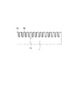
初めに、本発明に係る医療用チューブの製造方法および製造装置を用いて製造される気管チューブについて説明する。図1は、本発明の一実施形態としての医療用チューブの製造方法および製造装置を用いて製造される気管チューブ1を気管内に留置した状態を示す図である。図2は、気管チューブ1における医療用チューブとしてのチューブ本体2を単体で示す斜視図である。図3は、図2に示すチューブ本体2の拡大断面図であり、チューブ本体2の内面に形成された微細凹凸構造100を示す。図4A,4Bは、図3に示す微細凹凸構造100の上面図である。図5は、気管チューブ1を基端側から見た図である。図1に示すように、気管チューブ1は、チューブ本体2と、このチューブ本体2の外周面上に取り付けられた収縮及び拡張可能なカフ3と、チューブ本体2の一方の端部に装着されたフランジ部材4とを備える。
<Tracheal tube>
First, a tracheal tube manufactured using the method and apparatus for manufacturing a medical tube according to the present invention will be described. FIG. 1 is a diagram showing a state in which a
図2に示すように、チューブ本体2は、先端5を含む先端部8と、チューブ本体2の内周面の中心軸線O1の延在方向(以下、単に「中心軸線方向A」と記載する。)において先端部8の基端6側で連続し、外周面上にカフ3が取り付けられるカフ装着部9と、このカフ装着部9の基端6側で連続する湾曲部10と、この湾曲部10の基端6側で連続し、基端6を含む基端部11と、を備える。
As shown in FIG. 2, the tube
チューブ本体2は、中心軸線方向Aにおいて先端5から基端6まで貫通する中空部7を区画している。また、チューブ本体2は、壁内に形成され、基端面に区画された基端開口から中心軸線方向Aに延在する第1〜第3ルーメン12〜14を備える。中空部7により、気管チューブ1が外方から気管内に挿入されて留置されている状態において、気道を確保することができる。第1ルーメン12は、第1基端開口12aからカフ3よりも基端6側に設けられた吸引口まで延在しており、気管内に留置されている状態のカフ3よりも気管上流側(顎側)に貯留する痰、唾液、誤嚥物、血液などの異物Xを吸引して除去するために用いられる。第2ルーメン13は、第2基端開口13aからカフ3よりも先端5側に設けられた吸引口まで延在しており、気管内に留置されているカフ3よりも気管下流側(気管分岐部側)で、先端部8近傍に貯留する痰等の異物Xを吸引して除去するために用いられる。第3ルーメン14は、第3基端開口14aからカフ3の位置に設けられた連通口14bまで延在しており、カフ3を収縮及び拡張させるために用いられる。なお、壁内に区画された小径の第1〜第3ルーメン12〜14についても中空部であるが、説明の便宜上、気道を確保するための大径の中空部7と区別するため、ここでは「ルーメン」と記載する。
The
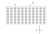
図3に示すように、医療用チューブとしてのチューブ本体2の内周面には、微細凹凸構造100が形成されている。微細凹凸構造100は、数μm〜数百μmの凹凸により構成されている。微細凹凸構造100が形成された領域は痰の付着を抑制する性質(以下、「撥痰性」と記載する。)を有する。チューブ本体2の内周面に微細凹凸構造100を形成する方法の詳細は後述する。微細凹凸構造100は、チューブ本体2の内周面の全面に亘って形成してもよく、また、内周面の一部のみに形成してもよい。なお、微細凹凸構造100の具体例としては、ライン&スペース(L&S)構造などのチューブ本体2の中心軸線方向Aに連続する構造だけでなく、複数の柱状、錐状、錐台状の突起や、複数の窪み部や、これらを組み合わせたものなどを配置した不連続な構造であってもよい。
As shown in FIG. 3, the fine
図4Aおよび図4Bを参照して、微細凹凸構造100の構成について、より詳細に説明する。
With reference to FIG. 4A and FIG. 4B, the structure of the fine concavo-
図4Aは、微細凹凸構造100がライン&スペース構造である場合の上面図であり、図4Aの横方向がチューブ本体2の中心軸線方向Aを示し、縦方向がチューブ本体2の周方向Bを示す。上述したように、微細凹凸構造100は、数μm〜数百μmサイズ、好ましくは数μm〜数十μmサイズの凹凸構造である。微細凹凸構造100がライン&スペース構造である場合、図4Aに示すように、チューブ本体2の中心軸線方向Aに延在する凸リブ101と凹溝102とが、周方向Bにおいて交互に配置された構造とすることができる。
4A is a top view when the fine concavo-
また、図4Bは、微細凹凸構造100が複数の突起103が配置されたピラー構造である場合の上面図であり、図4Bの横方向がチューブ本体2の中心軸線方向Aを示し、縦方向がチューブ本体2の周方向Bを示す。上述したように、微細凹凸構造100は、数μm〜数百μmサイズ、好ましくは数μm〜数十μmサイズの凹凸構造である。図4Bでは、円錐台形状の突起103が所定の配列で配置されている。
4B is a top view when the fine
なお、ラインアンドスペース構造は、周方向Bに延在する凸リブ101と凹溝102とが、中心軸線方向Aにおいて交互に配置される構造であってもよい。但し、ラインアンドスペース構造を有する面上の痰などの異物X(図1参照)は、凸リブ101及び凹溝102の延在方向に移動し易いため、異物Xがチューブ本体2内に留まることがないように、凸リブ101及び凹溝102を中心軸線方向Aに延在する図4Aに示す構成とすることが好ましい。また、ピラー構造を構成する突起103の形状は、図4Bに示す円錐台形状に限定されるものではなく、上述したように、円錐形状、円柱形状、三角錐形状又はその他の多角錐形状、角柱形状等とすることもできる。
The line and space structure may be a structure in which the
上述したように、微細凹凸構造100は、数μm〜数百μmサイズ、好ましくは数μm〜数十μmサイズの凹凸構造であり、この条件の下、隣接する、ラインアンドスペース構造における凸リブ101又はピラー構造における突起103(以下、凸リブ101及び突起103を単に「凸部」と記載する。)の中心間の距離は、10μm〜100μmとすることが好ましく、10μm〜50μmとすることがより好ましい。100μmより大きいと、痰が凸部間に入り込み易くなり、撥痰性の効果が小さくなる。また、10μm未満の場合には、痰と凸部との接触面積が大きくなり、撥痰性の効果が小さくなる。
As described above, the fine concavo-
また、微細凹凸構造100のサイズが上記条件の下では、各凸部の頂面105(図3参照)の最大幅は、0.01μm〜50μmとすることが好ましく、1μm〜50μmとすることがより好ましく、1μm〜30μmとすることが更により好ましく、1μm〜20μmとすることが特に好ましい。50μmより大きいと、痰との接触面積が大きくなり、撥痰性の効果が小さくなる。また、0.01μm未満の場合には、凸部の成形が難しく、形状安定性が低下するおそれがある。なお、微細凹凸構造100がラインアンドスペース構造の場合、各凸部の頂面105(図3参照)の最大幅とは、凸リブ101の延在方向と直交する方向の頂面105の最大長さとなる。
Moreover, when the size of the fine concavo-
更に、微細凹凸構造100のサイズが上記条件の下、微細凹凸構造100の凸部の最大高さを数μm〜数百μmサイズ、好ましくは数μm〜数十μmサイズとする。
Furthermore, the size of the fine concavo-
図3を再び参照すると、微細凹凸構造100の表面にはフッ素コート層200が形成されている。フッ素コート層200はフッ素樹脂を主成分とするものであれば特に限定されない。フッ素樹脂としては、例えば、ポリテトラフルオロエチレン(PTFE)、ポリクロロトリフルオロエチレン(PCTFE、CTFE)、ポリフッ化ビニリデン(PVDF)、ポリフッ化ビニル(PVF)、ペルフルオロアルコキシフッ素樹脂(PFA)、四フッ化エチレン・六フッ化プロピレン共重合体(FEP)、エチレン・四フッ化エチレン共重合体(ETFE)、エチレン・クロロトリフルオロエチレン共重合体(ECTFE)等を用いることができる。
Referring to FIG. 3 again, a
チューブ本体2の構成材料としては、例えば、シリコーン、軟質ポリ塩化ビニル等のポリ塩化ビニル、ポリエチレン、ポリプロピレン、環状ポリオレフィン、ポリスチレン、ポリ−(4−メチルペンテン−1)、ポリカーボネート、アクリル樹脂、アクリロニトリル−ブタジエン−スチレン共重合体、ポリエチレンテレフタレート等のポリエステル、ブタジエン−スチレン共重合体、ポリアミド(例えば、ナイロン6、ナイロン6・6、ナイロン6・10、ナイロン12)のような各種樹脂を用いることができる。その中でも、成形が容易であるという点で、軟質ポリ塩化ビニル、ポリプロピレン、環状ポリオレフィン、ポリエステル、ポリ−(4−メチルペンテン−1)のような樹脂を用いることが好ましい。
As a constituent material of the
カフ3は、気管チューブ1を気管内の所定の位置で留置させるために用いられる。具体的に、カフ3は、第3ルーメン14を通じて流体が供給されると拡張し、流体が吸引されると収縮する。カフ3が拡張した状態において、カフ3の外面は気管内壁と密着する。カフ3の外面と気管内壁との摩擦力等によって、カフ3が気管内周面に挟持される。このようにして、気管内でのカフ3の位置が固定され、気管チューブ1を気管内の所定の位置で留置させることができる。
The cuff 3 is used to place the
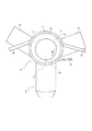
フランジ部材4は、図1に示すようにチューブ本体2の基端部11(図2等参照)に装着されており、チューブ本体2を体外から気管内に挿入して気管チューブ1を留置した際に、皮膚に当接することで、先端部8を気管内の適切な位置に固定する。図1及び図5に示すように、フランジ部材4は、チューブ本体2の基端部11が内挿され、チューブ本体2と嵌合することでチューブ本体2に対して装着される円筒状の筒部17と、この筒部17の外壁から径方向外側に向かって突出し、気管チューブ1を留置した状態で皮膚に当接する板状のフランジ部18と、を備える。なお、図5では、説明の便宜上、チューブ本体2の第1ルーメン12、第2ルーメン13及び第3ルーメン14の位置を二点鎖線により示している。
As shown in FIG. 1, the flange member 4 is attached to the base end portion 11 (see FIG. 2 and the like) of the
図5に示すように、筒部17には、フランジ部18よりも基端側の位置に、上述した第1ルーメン12、第2ルーメン13及び第3ルーメン14それぞれと連通する連通孔17a、17b及び17cが区画されており、筒部17内にチューブ本体2の基端部11が嵌合することにより装着されている状態において、第1ルーメン12、第2ルーメン13及び第3ルーメン14は、対応する連通孔17a、17b、17cを介して、気管チューブ1の外方と連通しており、この連通孔17a〜17cそれぞれに、チューブ本体2とは別の医療用チューブが接続されている。
As shown in FIG. 5, the
具体的に、第1ルーメン12は、筒部17に形成された対応する連通孔17aを通じて、気管チューブ1の基端側で気管チューブ1の外方と連通している。従って、体外に露出している筒部17の連通孔17aに一端が嵌合した医療用チューブとしての吸引用チューブ19の他端にシリンジまたは吸引ポンプ等を接続して吸引を行えば、体外から第1ルーメン12を通じて痰等の異物Xを吸引することができる。また、第2ルーメン13についても、第1ルーメン12と同様であり、医療用チューブとしての吸引用チューブ40、筒部17に形成された対応する連通孔17b及び第2ルーメン13を通じて異物Xを吸引することができる。
Specifically, the
更に、第3ルーメン14は、筒部17に形成された対応する連通孔17cを通じて、気管チューブ1の基端側で気管チューブ1の外方と連通している。従って、体外に露出している筒部17の連通孔17cに一端が嵌合した医療用チューブとしてのカフ用チューブ41の他端にシリンジ等を接続すれば、体外にあるシリンジ等の操作により、カフ3の環状空間への流体の供給や吸引を行うことができ、それによりカフ3の拡張及び収縮を操作することができる。
Further, the
なお、フランジ部材4の筒部17は、チューブ本体2の基端部11と同心円状に装着されており、チューブ本体2の周方向Bにおける第1ルーメン12の位置、第2ルーメン13の位置、及び第3ルーメン14の位置は、筒部17の対応する連通孔17a、17b、及び17cの周方向Bの位置の近傍とされている。そのため、各連通孔17a、17b、17cを短くすることができ、筒部17の連通孔17a、17b、及び17cの構成が複雑化することが抑制される。また、図5に示すように、吸引用チューブ19及び40、並びにカフ用チューブ41は、図5の平面視において、各連通孔17a、17b、17cからフランジ部18の突設されている方向に延在するように接続され、先端部8側には延在していない。このように接続することにより、気管チューブ1が気管内に留置された状態において、吸引用チューブ19及び40、並びにカフ用チューブ41が、患者の顎や首元にぶつかることが抑制され、気管チューブ1が留置される患者の不快感を軽減することができる。
The
フランジ部材4の構成材料としては、例えば、チューブ本体2と同様の材料で形成することができる。
As a constituent material of the flange member 4, for example, it can be formed of the same material as that of the
<チューブ本体2の製造装置>
図6は、本実施形態に係る医療用チューブの製造装置としてのチューブ本体2の製造装置20の構成例を示す断面図である。本実施形態に係る製造装置20は、軸方向に延在する中空部を有し、中空部の内面に微細凹凸構造100(図3、図4参照)が形成されていないチューブ2aの内面に微細凹凸構造100を形成し、医療用チューブとしてのチューブ本体2を製造する製造装置である。
<Manufacturing apparatus for
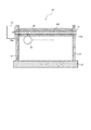
FIG. 6 is a cross-sectional view illustrating a configuration example of the
図6に示す製造装置20は、ステージ21と、支持部22,23と、金型24と、押し具25とを備える。
The
ステージ21上には、支持部22と支持部23とが所定の距離を隔てて対向するように設けられている。
On the
金型24は、金属製の柱状あるいは筒状の部材である。金型24は、ステージ21から離間するようにして、一端が支持部22により支持され、他端が支持部23により支持される。
The
図7A〜図7Cは、金型24を軸方向から見た断面形状の一例を示す図である。図6においては、筒状の金型24を示しているが、図7A〜図7Cにおいては、金型24は柱状であるとする。金型24は、例えば、円形(図7A)、六角形(図7B)、あるいは、八角形(図7C)の断面形状を有する。金型24の外面(表面)には、微細凹凸構造が形成された微細凹凸領域24aが軸方向に沿って設けられている。微細凹凸領域24aは、図7A〜図7Cに示すように、金型24の外面の一部にのみ設けられてもよいし、金型24の外面全面に設けられてもよい。微細凹凸領域24aに形成される微細凹凸構造のパターンは、チューブ本体2の内面に形成する微細凹凸構造100(図3、図4参照)の凹凸パターンを反転させたパターンである。
7A to 7C are diagrams illustrating an example of a cross-sectional shape of the
図6を再び参照すると、支持部22には、支持部23側に向かって突出する環状のフランジ22aが設けられている。また、支持部23には、フランジ22aと略等しい高さ位置に、支持部22側に向かって突出する環状のフランジ23aが設けられている。金型24の軸方向から見たフランジ22a,23aの外径は、チューブ2aの内径と同じか若干小さい。また、同方向から見たフランジ22a,23aの内径は、金型24の外径と同じかそれより大きい。そのため、図6に示すように、チューブ2aの中空部に金型24が挿入され、チューブ2aがフランジ22a,23aに支持(固定)された状態で、金型24の外面とチューブ2aの内面との間には空隙が生じる。なお、フランジ22a,23aを金型24の軸方向の端部の外面に形成し、フランジ22a,23aの間の位置で、金型24の外面とチューブ2aの内面との間に空隙を形成する構成としてもよい。
Referring to FIG. 6 again, the
図6に示す金型24は上述したように筒状であり、この金型24には、軸方向に貫通する貫通部24bが設けられている。貫通部24bが設けられていることで、金型24内に軸方向に沿う気流を導入することができ、これにより金型24を介してチューブ2aを冷却することができる。
The
押し具25は、図8に示すように、円盤状の部材であり、中心軸25aを中心として回転することができる。また、押し具25は、中心軸25aが金型24の軸方向と直交するように設けられており、金型24の軸方向に沿って回転しながら移動可能である。
As shown in FIG. 8, the
図9A,9Bは、押し具25を中心軸25aと直交する方向から見た図である。押し具25は、その径方向外側に位置する円周部分が、例えば、図9Aに示すように、単純な周面であってもよく、また、図9Bに示すように、径方向内側に窪んだ(例えば、半円状に凹んだ)凹状周面であってもよい。図9Bの凹状周面とすれば、図9Aの単純な周面とする場合と比較して、押し具25の円周部分とチューブ2aの外面との接触面積をより広く確保できる。
9A and 9B are views of the
押し具25は、円周部分が金型24との間に一定の距離を保ちつつ、金型24の軸方向に沿って移動可能に設置される。押し具25と金型24との間の距離は、チューブ2aの壁部の厚さと同じかそれ以下である。したがって、押し具25は、チューブ2aを金型24との間で挟み込んだ状態(チューブ2aの内面が金型24の微細凹凸領域24aに接するようにチューブ2aを押圧した状態)で、金型24の軸方向に沿って移動することができる。金型24と押し具25とでチューブ2aを挟み込んだ状態で、押し具25が金型24の軸方向に沿って移動することで、チューブ2aの内面に、微細凹凸領域24aに形成された微細凹凸構造を反転させたパターンの微細凹凸構造100(図3、図4参照)を形成(転写)することができる。図7A〜図7Cに示すように、金型24の外面の一部に微細凹凸領域24aが形成されている場合、押し具25は、円周部分が金型24の微細凹凸領域24aと対向するように設定される。
The
なお、金型24および押し具25の少なくとも一方に、ヒーター、超音波発生装置、高周波発生装置などの、チューブ2aを加熱する加熱装置を設けてもよい。この場合、加熱装置によりチューブ2aを加熱しながら、押し具25によりチューブ2aを押圧することで、チューブ2aの内面への微細凹凸構造の転写をしやすくすることができる。加熱装置を設ける位置としては、例えば、金型24の貫通部24bが挙げられるが、この位置に限られるものではない。押し具25によるチューブ2aの金型24への押圧によりチューブ2aの内面に微細凹凸構造100を転写した後、冷却装置によりチューブ2aを冷却することが好ましい。冷却装置としては、微細凹凸構造100を転写後のチューブ2aを冷却できるものであればよい。したがって、例えば、冷却装置を、チューブ2a内に気流を発生させる冷却ファンなどの送風装置27とすることができる。送風装置27により、例えば、図6に示すように、金型24の貫通部24bに気流を導入して、金型24を介してチューブ2aを速やかに冷却することで、チューブ2aの内面に微細凹凸構造100を安定的に形成することができる。なお、送風装置27により、金型24の外面とチューブ2aの内面との間に、金型24の軸方向に沿う気流を発生させるようにしてもよい。
In addition, you may provide the heating apparatus which heats the
本実施形態においては、押し具25は、円盤形状である例を用いて説明したが、これに限られるものではなく、例えば、図10に示すように、押し具25は、長尺な円柱形状又は円筒形状であってもよい。図10では円柱形状の押し具25を示している。この場合、押し具25の軸方向を、金型24の軸方向と平行にし、押し具25の円周部分が金型24との間に一定の距離を保つように設置される。金型24と円柱状の押し具25との間の距離は、図6と同様に、チューブ2aの壁部の厚さと同じかそれ以下である。そして、押し具25は、金型24の周方向に沿って回転可能に設けられる。
In the present embodiment, the
円柱状の押し具25がチューブ2aを押圧しながら、金型24の周方向に沿って回転することで、金型24の微細凹凸領域24aに形成された微細凹凸構造を反転させたパターンの微細凹凸構造100をチューブ2aの内面に形成(転写)することができる。なお、図10に示す製造装置20においては、微細凹凸領域24aは、金型24の外面全体に形成されていることが望ましい。
The columnar
また、図11に示すように、金型24の周囲に配置されたチューブ2aの周囲に、チューブ2aを冷却する気流を発生させる冷却ファンなどの、上述した送風装置27とは別の冷却装置26を設けてもよい。なお、図11では、柱状の金型24を示しているが、図6に示すような筒状の金型24としてもよい。また、図10では、円盤形状の押し具25を示しているが、図10に示すような円柱形状又は円筒形状の押し具25としてもよい。
Further, as shown in FIG. 11, a cooling device 26 different from the above-described
<チューブ本体2の製造方法>
次に、本実施形態に係る医療用チューブとしてのチューブ本体2の製造方法について説明する。
<Method for
Next, the manufacturing method of the tube
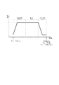
図12は、本実施形態に係る医療用チューブの製造方法としてのチューブ本体2の製造方法を示すフロー図である。図13は、チューブ本体2の製造フローにおけるチューブ2aの温度変化を示す図である。なお、以下では、押し具25が円盤形状の製造装置20(図6)を用いる例を用いて説明する。
FIG. 12 is a flowchart showing a method for manufacturing the
まず、内面に微細凹凸構造が形成されていないチューブ2aが金型24にセットされる(ステップS11)。具体的には、チューブ2aの中空部に金型24が挿入される。
First, the
次に、金型24の周囲に位置するチューブ2aを、金型24および押し具25の少なくとも一方に設けられた加熱装置により予備加熱する(ステップS12)。加熱装置による加熱により、図13に示すように、チューブ2aの温度は所定の設定温度Tまで上昇する。
Next, the
予備加熱によりチューブ2aの温度が設定温度Tに達してから所定時間が経過すると、チューブ2aの内面への微細凹凸構造の転写を開始する(ステップS13)。具体的には、押し具25によりチューブ2aを金型24に押圧しつつ、押し具25を回転させながら金型24の軸方向に沿って移動させる。
When a predetermined time elapses after the temperature of the
押し具25の金型24の軸方向に沿った移動が終了すると、加熱手段による加熱を停止し、金型24の貫通部24bに気流を導入して、所定時間(例えば、1分間)だけ、チューブ2aを冷却する(エア冷却)。
When the movement of the
加熱されたチューブ2aが押し具25により金型24に押し付けられることで、チューブ2aが金型24に張り付いてしまう。そこで、エア冷却後、チューブ2aを金型24から剥がす(ステップS15)。この工程を、以下では、金型剥がし工程と称する。
When the
金型剥がし工程の後、微細凹凸構造を形成する必要がある領域全体への転写が終了した場合には、金型24からチューブ2aを取り外す(ステップS16)。こうすることで、チューブ2aの内面に微細凹凸構造100が形成される。微細凹凸構造を形成する必要がある領域全体への転写が終了していない場合には、チューブ2aを回転させ(ステップS17)、ステップS12の処理に戻る。
After the mold peeling process, when the transfer to the entire area where the fine uneven structure needs to be formed is completed, the
チューブ2aの内面に微細凹凸構造100が形成され、チューブ2aを金型24から取り外した後、チューブ2aの内面に形成された微細凹凸構造100の表面にフッ素コーティングを施し、フッ素コート層200(図3参照)を形成する(ステップS18)。フッ素コート層200を形成する工程について、具体的に説明する。まず、チューブ2aの内面に形成された微細凹凸構造100表面に、上述したフッ素樹脂を含むフッ素コーティング剤を塗着する。フッ素コーティング剤を塗着する方法としては、フッ素コーティング剤が含まれる溶媒中に、内面に微細凹凸構造100が形成されたチューブ2aを浸漬する方法、フッ素コーティング剤が含まれる溶媒を、チューブ2aの中空部に流し込む方法、スプレーでチューブ2aの内面に吹き付ける方法、あるいは箆部材を用いてチューブ2aの内面に塗る方法などが挙げられる。次に、フッ素コーティング剤が含まれる溶媒が塗着された状態でチューブ2aを乾燥させる。溶媒が除去されフッ素コーティング剤の皮膜が形成される。次に、フッ素コーティング剤を硬化し、チューブ2aの内面との結合を形成する。フッ素コーティング剤を硬化する態様の一例として、例えば、チューブ2aをオーブン(不図示)に投入し、オーブン内で所定時間、所定の温度で加熱して硬化することができる。設定温度は、好ましくは、約70〜100度、より好ましくは80度とし、加熱時間は好ましくは約30〜90分とする。このようにして、微細凹凸構造100の表面にフッ素コート層200を形成する。
After forming the fine
微細凹凸構造100の表面にフッ素コーティングを施すことにより、チューブ2aの内面の撥水性、撥油性、耐摩擦性を向上させることができると共に、チューブ2aの内面に形成された微細凹凸構造100の強度を向上させることができる。そのため、例えば、図2に示すチューブ本体2の湾曲部10を形成するためにチューブ2aを湾曲させる工程などにおいて、微細凹凸構造100を損傷しにくくすることができる。但し、上述したフッ素コーティングを施す工程は、チューブ2aを湾曲させた後に行ってもよい。
By applying a fluorine coating on the surface of the fine concavo-
なお、医療用チューブとしてのチューブ本体2の製造工程のうち、チューブ2aの内面に微細凹凸構造を形成する工程以外の工程は、従来のチューブ本体の製造工程と同様であるため、説明を省略する。
Of the manufacturing processes of the tube
図14は、押し具25によるチューブ2aの押し潰し量と転写時の設定温度Tとをパラメータとした微細凹凸構造の形成状態の評価結果を示す図である。図14においては、ポリ塩化ビニルにより構成されるチューブ2aを用い、チューブ2aの押し潰し量を、0.09mm,0.26mm,0.43mmとし、設定温度Tを155℃、165℃、175℃とした場合の評価結果を示している。なお、図14において、「良好」とは、チューブ本体2の内面の全体に微細凹凸構造が形成された状態であることを示す。また、「不良」とは、微細凹凸構造の形成が一部でも不十分な部分があることを示す。
FIG. 14 is a diagram showing the evaluation result of the formation state of the fine concavo-convex structure with the amount of crushing of the
図14に示すように、押し潰し量が0.09mmの場合には、設定温度Tによらず、評価結果は「不良」であった。また、設定温度Tが155℃である場合には、押し潰し量によらず、評価結果は「不良」であった。一方、押し潰し量が0.26mm以上、かつ、設定温度Tが165℃以上である場合には、評価結果は「良好」であった。このことから、チューブ本体2の内面への微細凹凸構造の良好な転写には、所定値以上の温度、および、所定値以上の押し潰し量(押圧力)が必要であることが分かる。
As shown in FIG. 14, when the crushing amount was 0.09 mm, the evaluation result was “defective” regardless of the set temperature T. When the set temperature T was 155 ° C., the evaluation result was “bad” regardless of the amount of crushing. On the other hand, when the crushing amount was 0.26 mm or more and the set temperature T was 165 ° C. or more, the evaluation result was “good”. From this, it can be understood that a temperature of a predetermined value or higher and a crushing amount (pressing force) of a predetermined value or higher are necessary for good transfer of the fine uneven structure to the inner surface of the
図15は、金型剥がし工程後のチューブ2aの回転角度をパラメータとして微細凹凸構造の形成状態の評価結果を示す図である。図15においては、内径が8mm、外径が11.5mm、長さが100mmのチューブ2a、および、図9Bに示す、径方向内側に窪んだ凹状周面を有する円盤状の押し具25(直径27mm、窪みは、曲率半径=6mm、幅8mm)を用い、チューブ2aの回転角度を、30°,45°,60°,72°,90°とした場合の評価結果を示している。なお、図15において、「良好」とは、チューブ本体2の内面全体に微細凹凸構造が形成された状態を示す。また、「不良」とは、チューブ本体2の内面に微細凹凸構造が形成されていない部分がある状態を示す。また、「重複」とは、チューブ本体2の内面全体に微細凹凸構造が転写されているが、重なり部(転写された微細凹凸構造が重複してしまう部分)が多くなり過ぎることにより適切な微細凹凸構造にならず、好ましくない状態を示す。
FIG. 15 is a diagram showing the evaluation result of the formation state of the fine concavo-convex structure with the rotation angle of the
図15に示すように、回転角度が30°の場合には、評価結果は「重複」であった。回転角度が30°の場合に評価結果が「重複」となる(重なり部が生じる)のは、1回の転写によって転写される周方向の転写距離(角度)が、チューブの回転距離(角度)と比べて大きいためである。また、回転角度が60°以上の場合には、評価結果は「不良」であった。一方、回転角度が45°の場合には、評価結果は「良好」であった、このことから、チューブ2aのサイズ(径)、押し具25の円周部分の形状などに応じて、回転角度を調整することで、チューブ本体2の内面への微細凹凸構造の良好な転写が可能であることが分かる。
As shown in FIG. 15, when the rotation angle was 30 °, the evaluation result was “overlapping”. When the rotation angle is 30 °, the evaluation result is “overlapping” (the overlapping portion is generated). The circumferential transfer distance (angle) transferred by one transfer is the tube rotation distance (angle). This is because it is larger than Further, when the rotation angle was 60 ° or more, the evaluation result was “defective”. On the other hand, when the rotation angle is 45 °, the evaluation result was “good”. From this, the rotation angle depends on the size (diameter) of the
このように本実施形態に係る医療用チューブの製造方法は、内面に微細凹凸構造が形成されていないチューブ2aに、外面に微細凹凸構造が形成された金型24を挿入する挿入工程と、金型24の微細凹凸構造がチューブ2aの内面に接触するようにチューブ2aを金型24に押し当てる押し当て工程とを含む。
As described above, the manufacturing method of the medical tube according to the present embodiment includes an insertion step of inserting the
外面に微細凹凸構造が形成された金型24をチューブ2aに挿入した状態で、金型24の微細凹凸構造がチューブ2aの内面に接触するようにチューブ2aを金型24に押し当てることで、金型24に形成された微細凹凸構造に対応する微細凹凸構造がチューブ2aの内面に形成されるので、内面に微細凹凸構造100が形成されたチューブ本体2を製造することができる。特に、本実施形態に係る製造方法によれば、押し具25を金型24に押し当てることによりチューブ2aに微細凹凸構造を転写するため、押出成形などと異なり、チューブ本体2の軸方向に不連続な突起などの微細凹凸構造を形成することも容易である。
By pressing the
本発明に係る医療用チューブの製造方法および製造装置は、上述した実施形態で説明した具体的な構成に限られるものではなく、特許請求の範囲に記載した発明の要旨を逸脱しない範囲で、種々の変更を行うことが可能である。例えば、上述した実施形態では、医療用チューブとしてのチューブ本体2の製造方法について説明したが、本発明に係るチューブの製造方法は、気管チューブのチューブ本体に限らず、他の用途や目的で使用される医療用チューブの製造方法としても適用可能である。
The manufacturing method and the manufacturing apparatus of the medical tube according to the present invention are not limited to the specific configurations described in the above-described embodiments, and various types are possible without departing from the gist of the invention described in the claims. It is possible to make changes. For example, in the above-described embodiment, the method for manufacturing the
本発明に係る製造方法および製造装置により製造可能な医療用チューブとしては、例えば、(1)胃管カテーテル、栄養カテーテル、経管栄養用チューブなどの経口もしくは経鼻的に消化器官内に挿入ないし留置されるカテーテル類;(2)酸素カテーテル、気管内チューブ、気管内吸引カテーテルなどの経口または経鼻的に気道ないし気管内に挿入ないし留置されるカテーテル類;(3)尿道カテーテル、導尿カテーテル、尿道バルーンカテーテルのカテーテルやバルーンなどの尿道ないし尿管内に挿入ないし留置されるカテーテル類;(4)吸引カテーテル、排液カテーテル、直腸カテーテルなどの各種体腔、臓器、組織内に挿入ないし留置されるカテーテル類;(5)輸液チューブ、IVH(intravenous hyperalimentationの略)カテーテル、サーモダイリューションカテーテル、血管造影用カテーテル、血管拡張用カテーテルおよびダイレーターあるいはイントロデューサーなどの血管内に間接的あるいは直接的に挿入ないし留置されるカテーテル類;(6)人工気管、人工気管支などの医療用人工管;(7)体外循環治療用の医療器具(人工肺、人工心臓、人工腎臓など)の回路類、などが挙げられる。 Examples of the medical tube that can be manufactured by the manufacturing method and the manufacturing apparatus according to the present invention include (1) Oral or nasal insertion or digestion into the digestive organ, such as a gastric tube catheter, nutritional catheter, and tube feeding tube. Indwelling catheters; (2) Oxygen catheters, endotracheal tubes, intratracheal aspiration catheters, or other catheters that are inserted or indwelled orally or intranasally into the trachea; (3) Urinary catheters, urinary catheters Urethra balloon catheter catheters, balloons and other urethra or catheters inserted or placed in the ureter; (4) inserted or placed in various body cavities, organs, tissues such as suction catheters, drainage catheters, rectal catheters, etc. Catheters; (5) infusion tubes, IVH (abbreviation for intravenous hyperalimentation) catheters, -Modulation catheters, angiographic catheters, vasodilator catheters and catheters that are inserted or placed indirectly or directly into blood vessels such as dilators or introducers; (6) artificial trachea, artificial bronchi, etc. Medical artificial tubes; (7) Circuits for medical devices for extracorporeal circulation treatment (artificial lungs, artificial hearts, artificial kidneys, etc.).
本発明に係る製造方法および製造装置により製造される各種医療用チューブによれば、広範囲の生物学的物質又は医療用液体が内面に付着することを抑制することができる。なお、「生物学的物質」としては、例えば、全血、血漿、血清、汗、便、尿、唾液、涙、膣液、前立腺液、歯肉滲出液、羊水、眼液、脳脊髄液、精液、痰、腹水、膿、鼻咽頭液、創傷浸出液、房水、硝子体液、胆汁、耳垢、内リンパ、外リンパ、胃液、粘液、腹液、胸水、皮脂、嘔吐物、これらの組み合わせからなる群、などが挙げられる。また、「医療用液体」としては、例えば、輸液剤、栄養剤、造影剤、肝動脈化学塞栓療法(TACE)などで使用される塞栓剤、などが挙げられる。 According to the various medical tubes manufactured by the manufacturing method and the manufacturing apparatus according to the present invention, it is possible to suppress adhesion of a wide range of biological substances or medical liquids to the inner surface. Examples of the “biological substance” include whole blood, plasma, serum, sweat, stool, urine, saliva, tears, vaginal fluid, prostate fluid, gingival exudate, amniotic fluid, eye fluid, cerebrospinal fluid, semen , Sputum, ascites, pus, nasopharyngeal fluid, wound exudate, aqueous humor, vitreous humor, bile, earwax, endolymph, perilymph, gastric fluid, mucus, ascites, pleural effusion, sebum, vomit, and combinations thereof , Etc. Examples of the “medical liquid” include infusion agents, nutrients, contrast agents, embolic agents used in hepatic artery chemoembolization (TACE), and the like.
本発明を図面および実施形態に基づき説明してきたが、当業者であれば本開示に基づき種々の変形または修正を行うことが容易であることに注意されたい。したがって、これらの変形または修正は本発明の範囲に含まれることに留意されたい。例えば、各ブロックあるいはステップなどに含まれる機能などは論理的に矛盾しないように再配置可能であり、複数のブロックあるいはステップを1つに組み合わせたり、或いは分割したりすることが可能である。 Although the present invention has been described based on the drawings and embodiments, it should be noted that those skilled in the art can easily make various variations or modifications based on the present disclosure. Therefore, it should be noted that these variations or modifications are included in the scope of the present invention. For example, functions included in each block or step can be rearranged so as not to be logically contradictory, and a plurality of blocks or steps can be combined into one or divided.
1 気管チューブ
2 チューブ本体(医療チューブ)
2a チューブ
3 カフ
4 フランジ部材
5 チューブ本体の先端
6 チューブ本体の基端
7 中空部
8 チューブ本体の先端部
9 チューブ本体のカフ装着部
10 チューブ本体の湾曲部
11 チューブ本体の基端部
12 第1ルーメン
12a 第1基端開口
13 第2ルーメン
13a 第2基端開口
14 第3ルーメン
14a 第3基端開口
14b 連通口
17 筒部
18 フランジ部
19,40 吸引用チューブ
20 製造装置
21 ステージ
22,23 支持部
22a,23a フランジ
24 金型
24a 微細凹凸領域
24b 貫通部
25 押し具
25a 中心軸
26 冷却装置
27 送風装置(冷却装置)
41 カフ用チューブ
100 微細凹凸構造
101 凸リブ
102 凹溝
103 突起
105 頂面
200 フッ素コート層
1
2a Tube 3 Cuff 4 Flange member 5 Tube body distal end 6 Tube body proximal end 7 Hollow portion 8 Tube body distal end portion 9 Tube body
41
Claims (11)
外面に微細凹凸構造を有する金型をチューブに挿入する挿入工程と、
前記金型の微細凹凸構造が前記チューブの内面に接触するように前記チューブを前記金型に押し当てる押し当て工程と、を含む製造方法。 A method for producing a medical tube having a fine relief structure on the inner surface,
An insertion step of inserting a mold having a fine relief structure on the outer surface into the tube;
And a pressing step of pressing the tube against the mold so that the fine concavo-convex structure of the mold contacts the inner surface of the tube.
前記押し当て工程では、押し具により前記チューブを前記金型に押し当てる、製造方法。 The manufacturing method according to claim 1,
In the pressing step, the tube is pressed against the mold by a pressing tool.
前記押し具は円筒形状又は円柱形状であり、
前記押し当て工程では、前記押し具を前記チューブの周方向に移動させながら、前記チューブに押し当てる、製造方法。 In the manufacturing method of Claim 2,
The pusher is cylindrical or columnar,
In the pressing step, the pressing tool is pressed against the tube while being moved in the circumferential direction of the tube.
前記押し具は円盤形状であり、
前記押し当て工程では、前記押し具を前記チューブの軸方向に移動させながら、前記チューブに押し当てる、製造方法。 In the manufacturing method of Claim 2,
The pusher has a disk shape,
In the pressing step, the pressing tool is pressed against the tube while being moved in the axial direction of the tube.
前記押し当て工程では、前記チューブを加熱装置により加熱しながら、前記押し具を前記チューブに押し当てる、製造方法。 In the manufacturing method as described in any one of Claim 1 to 4,
In the pressing step, the pressing tool is pressed against the tube while the tube is heated by a heating device.
前記加熱装置は、前記金型および前記押し具の少なくとも一方に設けられている、製造方法。 In the manufacturing method of Claim 5,
The said heating apparatus is a manufacturing method provided in at least one of the said metal mold | die and the said pressing tool.
前記加熱装置は、ヒーター、超音波発生装置または高周波発生装置である、製造方法。 In the manufacturing method of Claim 5 or 6,
The manufacturing method, wherein the heating device is a heater, an ultrasonic generator, or a high-frequency generator.
前記押し具を前記チューブに押し当てた後、前記加熱装置による前記チューブの加熱を停止するとともに、冷却装置により前記チューブを冷却する冷却工程をさらに含む製造方法。 In the manufacturing method as described in any one of Claim 5 to 7,
The manufacturing method further includes a cooling step of stopping the heating of the tube by the heating device and cooling the tube by a cooling device after the pressing tool is pressed against the tube.
前記冷却装置は、前記チューブ内に気流を発生させる送風装置であり、
前記冷却工程では、前記送風装置により前記チューブ内に気流を発生させて前記チューブを冷却する、製造方法。 In the manufacturing method of Claim 8,
The cooling device is a blower that generates an air flow in the tube,
In the cooling step, the air blowing device generates an air flow in the tube to cool the tube.
前記金型の押し当てにより前記チューブの内面に形成された微細凹凸構造にフッ素コーティングを施す工程をさらに含む、製造方法。 In the manufacturing method as described in any one of Claim 1 to 9,
The manufacturing method which further includes the process of performing a fluorine coating to the fine concavo-convex structure formed in the inner surface of the said tube by pressing the said metal mold | die.
外面に微細凹凸構造を有し、チューブ内に挿入可能な金型と、
前記金型の微細凹凸構造が前記チューブの内面に接触するように前記チューブを押圧可能な押し具と、を備える製造装置。 A medical tube manufacturing apparatus having a fine relief structure on the inner surface,
A mold having a fine concavo-convex structure on the outer surface and insertable into the tube;
A pressing device capable of pressing the tube so that the fine uneven structure of the mold contacts the inner surface of the tube.
Priority Applications (1)
| Application Number | Priority Date | Filing Date | Title |
|---|---|---|---|
| JP2016056612A JP6652869B2 (en) | 2016-03-22 | 2016-03-22 | Method and apparatus for manufacturing medical tubing |
Applications Claiming Priority (1)
| Application Number | Priority Date | Filing Date | Title |
|---|---|---|---|
| JP2016056612A JP6652869B2 (en) | 2016-03-22 | 2016-03-22 | Method and apparatus for manufacturing medical tubing |
Publications (2)
| Publication Number | Publication Date |
|---|---|
| JP2017169658A true JP2017169658A (en) | 2017-09-28 |
| JP6652869B2 JP6652869B2 (en) | 2020-02-26 |
Family
ID=59971015
Family Applications (1)
| Application Number | Title | Priority Date | Filing Date |
|---|---|---|---|
| JP2016056612A Active JP6652869B2 (en) | 2016-03-22 | 2016-03-22 | Method and apparatus for manufacturing medical tubing |
Country Status (1)
| Country | Link |
|---|---|
| JP (1) | JP6652869B2 (en) |
Citations (4)
| Publication number | Priority date | Publication date | Assignee | Title |
|---|---|---|---|---|
| JPH0824342A (en) * | 1994-07-11 | 1996-01-30 | Terumo Corp | Catheter tube and inside surface processing method for the tube |
| JPH10118188A (en) * | 1996-10-24 | 1998-05-12 | Terumo Corp | Medical treatment appliance for insertion into celom and its production |
| JP2006102099A (en) * | 2004-10-05 | 2006-04-20 | Nippon Sherwood Medical Industries Ltd | Tracheotomy tube |
| JP2011024945A (en) * | 2009-07-29 | 2011-02-10 | Terumo Corp | Housing tube for catheter |
-
2016
- 2016-03-22 JP JP2016056612A patent/JP6652869B2/en active Active
Patent Citations (4)
| Publication number | Priority date | Publication date | Assignee | Title |
|---|---|---|---|---|
| JPH0824342A (en) * | 1994-07-11 | 1996-01-30 | Terumo Corp | Catheter tube and inside surface processing method for the tube |
| JPH10118188A (en) * | 1996-10-24 | 1998-05-12 | Terumo Corp | Medical treatment appliance for insertion into celom and its production |
| JP2006102099A (en) * | 2004-10-05 | 2006-04-20 | Nippon Sherwood Medical Industries Ltd | Tracheotomy tube |
| JP2011024945A (en) * | 2009-07-29 | 2011-02-10 | Terumo Corp | Housing tube for catheter |
Also Published As
| Publication number | Publication date |
|---|---|
| JP6652869B2 (en) | 2020-02-26 |
Similar Documents
| Publication | Publication Date | Title |
|---|---|---|
| JP5271898B2 (en) | Endotracheal cuff and techniques for its use | |
| US10207083B2 (en) | Balloon catheter and method for manufacturing balloon | |
| JP6717626B2 (en) | Medical tube manufacturing method and medical tube | |
| JP6652869B2 (en) | Method and apparatus for manufacturing medical tubing | |
| JP2017169654A (en) | Method for manufacturing medical tube and medical tube | |
| WO2018120982A1 (en) | Double-layered drainage tube | |
| JP2017169663A (en) | Medical tube manufacturing method and manufacturing apparatus | |
| JP2017169660A (en) | Medical tube manufacturing method and manufacturing apparatus | |
| JP6621692B2 (en) | Manufacturing method of medical tube | |
| JP6718265B2 (en) | Medical tube manufacturing method | |
| JP2017169665A (en) | Method for manufacturing medical tube | |
| JP2017169664A (en) | Method for manufacturing medical tube | |
| JP6332922B2 (en) | Balloon catheter and balloon manufacturing method used for balloon catheter | |
| JP2017169662A (en) | Method for manufacturing medical tube | |
| JP2022013611A (en) | Balloon catheter production method and balloon catheter | |
| JP2017169653A (en) | Method for manufacturing medical tube | |
| EP3808533B1 (en) | Method for manufacturing balloon catheter by using heat-curable resin and apparatus therefor | |
| JP2017169661A (en) | Method for manufacturing medical tube | |
| JP2013070882A (en) | Balloon catheter | |
| JP5822290B2 (en) | Method for manufacturing catheter tube | |
| JP6891167B2 (en) | Balloon catheter and manufacturing method of balloon catheter | |
| JP6573896B2 (en) | Tracheal tube that can be inserted into the trachea | |
| CN115670769B (en) | Digestive tract membranous tube and preparation method thereof | |
| JP7431007B2 (en) | Balloon catheter and balloon manufacturing method | |
| JP2021137128A (en) | Balloon catheter |
Legal Events
| Date | Code | Title | Description |
|---|---|---|---|
| A621 | Written request for application examination |
Free format text: JAPANESE INTERMEDIATE CODE: A621 Effective date: 20190109 |
|
| A977 | Report on retrieval |
Free format text: JAPANESE INTERMEDIATE CODE: A971007 Effective date: 20191031 |
|
| A131 | Notification of reasons for refusal |
Free format text: JAPANESE INTERMEDIATE CODE: A131 Effective date: 20191119 |
|
| A521 | Request for written amendment filed |
Free format text: JAPANESE INTERMEDIATE CODE: A523 Effective date: 20191210 |
|
| TRDD | Decision of grant or rejection written | ||
| A01 | Written decision to grant a patent or to grant a registration (utility model) |
Free format text: JAPANESE INTERMEDIATE CODE: A01 Effective date: 20200114 |
|
| A61 | First payment of annual fees (during grant procedure) |
Free format text: JAPANESE INTERMEDIATE CODE: A61 Effective date: 20200124 |
|
| R150 | Certificate of patent or registration of utility model |
Ref document number: 6652869 Country of ref document: JP Free format text: JAPANESE INTERMEDIATE CODE: R150 |
|
| R250 | Receipt of annual fees |
Free format text: JAPANESE INTERMEDIATE CODE: R250 |
|
| R250 | Receipt of annual fees |
Free format text: JAPANESE INTERMEDIATE CODE: R250 |