JP2017166345A - Scroll compressor - Google Patents

Scroll compressor Download PDF

Info

Publication number
JP2017166345A
JP2017166345A JP2016050020A JP2016050020A JP2017166345A JP 2017166345 A JP2017166345 A JP 2017166345A JP 2016050020 A JP2016050020 A JP 2016050020A JP 2016050020 A JP2016050020 A JP 2016050020A JP 2017166345 A JP2017166345 A JP 2017166345A
Authority
JP
Japan
Prior art keywords
movable
wrap
end plate
oil supply
oil
Prior art date
Legal status (The legal status is an assumption and is not a legal conclusion. Google has not performed a legal analysis and makes no representation as to the accuracy of the status listed.)
Pending
Application number
JP2016050020A
Other languages
Japanese (ja)
Inventor
康夫 水嶋
Yasuo Mizushima
康夫 水嶋
泰弘 村上
Yasuhiro Murakami
泰弘 村上
亮太 中井
Ryota Nakai
亮太 中井
匡宏 野呂
Masahiro Noro
匡宏 野呂
Current Assignee (The listed assignees may be inaccurate. Google has not performed a legal analysis and makes no representation or warranty as to the accuracy of the list.)
Daikin Industries Ltd
Original Assignee
Daikin Industries Ltd
Priority date (The priority date is an assumption and is not a legal conclusion. Google has not performed a legal analysis and makes no representation as to the accuracy of the date listed.)
Filing date
Publication date
Application filed by Daikin Industries Ltd filed Critical Daikin Industries Ltd
Priority to JP2016050020A priority Critical patent/JP2017166345A/en
Publication of JP2017166345A publication Critical patent/JP2017166345A/en
Pending legal-status Critical Current

Links

Images

Landscapes

  • Rotary Pumps (AREA)
  • Applications Or Details Of Rotary Compressors (AREA)

Abstract

PROBLEM TO BE SOLVED: To provide a highly-reliable and efficient scroll compressor in which contact between a lap tip and an end plate can be prevented and leakage of a refrigerant passing through a clearance between the lap tip and the end plate can be suppressed.SOLUTION: In the scroll compressor, a clearance between the tip 312a of a fixed side lap 312 and a movable side end plate 321 and a clearance between the tip 322a of a movable side lap 322 and a fixed side end plate 311 are formed to become wider from the outer peripheral side toward the inner peripheral side under ordinary temperature. The fixed side lap is formed with a first oil supply hole 81 which is opened outside a first clearance minimum region at the tip of the fixed side lap, where the clearance between the tip of the fixed side lap and the movable side end plate becomes minimum, and which is supplied with oil from a low oil storage space of a high pressure. The movable side lap is formed with a second oil supply hole 82 which is opened outside a second clearance minimum region at the tip of the movable side lap, where the clearance between the tip of the movable side lap and the fixed side end plate becomes minimum, and which is supplied with oil from the low oil storage space.SELECTED DRAWING: Figure 2

Description

スクロール圧縮機では、スクロールの内周側が外周側に比べて高温になりやすく、内周側ほどスクロールが大きく熱膨張する。そのため、スクロール全体の温度が均一な場合に、一方のスクロールのラップの先端(歯先)と、その先端が対向する他方のスクロールの鏡板との距離が一様であるという構成では、運転時に、ラップの先端と、その先端が対向する鏡板とが、スクロールの内周側ほど接触しやすいという問題がある。   In the scroll compressor, the inner peripheral side of the scroll is likely to be hotter than the outer peripheral side, and the scroll expands greatly toward the inner peripheral side. Therefore, when the temperature of the entire scroll is uniform, in the configuration in which the distance between the tip (tooth tip) of one scroll wrap and the end plate of the other scroll facing the tip is uniform, during operation, There is a problem that the tip of the wrap and the end plate facing the tip are more likely to come into contact with the inner peripheral side of the scroll.

これに対し、特許文献1(国際公開第2014/155646号)のように、常温下で、一方のスクロールのラップの先端と、その先端が対向する他方のスクロールの鏡板との距離が内周側ほど大きくなるように、スクロールの鏡板に段差を設けたスクロール圧縮機が知られている。スクロール圧縮機がこのように構成されることで、スクロールの内周側が外周側に比べて高温になっても、スクロールの内周側における、ラップの先端と、これに対向する鏡板との接触を防止できる。   On the other hand, as in Patent Document 1 (International Publication No. 2014/155646), at normal temperature, the distance between the tip of one scroll wrap and the end plate of the other scroll facing the tip is the inner peripheral side. A scroll compressor is known in which a step is provided on the end plate of the scroll so as to become larger. By configuring the scroll compressor in this way, even when the inner peripheral side of the scroll becomes hotter than the outer peripheral side, the contact between the tip of the wrap and the end plate facing this on the inner peripheral side of the scroll is achieved. Can be prevented.

しかし、特許文献1(国際公開第2014/155646号)のように構成される場合、スクロールの内周側の温度上昇及び熱膨張による変形が比較的小さい運転条件では、ラップの先端と、これに対向する鏡板との隙間が比較的大きくなりやすい。その結果、この隙間を通って、高圧側の圧縮室の冷媒が低圧側の圧縮室へと漏れ、スクロール圧縮機の効率が低下するおそれがある。   However, when configured as in Patent Document 1 (International Publication No. 2014/155646), under the operating conditions in which the temperature rise on the inner peripheral side of the scroll and the deformation due to thermal expansion are relatively small, The gap with the facing end plate tends to be relatively large. As a result, the refrigerant in the compression chamber on the high pressure side leaks into the compression chamber on the low pressure side through this gap, and the efficiency of the scroll compressor may be reduced.

本発明の課題は、ラップの先端とその先端が対向する鏡板との接触を防止可能で、かつ、運転条件によらず、ラップの先端とその先端が対向する鏡板との隙間を通過する冷媒の漏れを抑制可能な、信頼性が高く効率のよいスクロール圧縮機を提供することにある。   An object of the present invention is to prevent the contact between the tip of the wrap and the end plate facing the end of the wrap, and the refrigerant passing through the gap between the end of the wrap and the end plate facing the tip regardless of the operating conditions. An object is to provide a highly reliable and efficient scroll compressor capable of suppressing leakage.

本発明の第1観点に係るスクロール圧縮機は、固定スクロールと、可動スクロールと、駆動部と、駆動軸と、を備える。固定スクロールは、固定側鏡板と、固定側鏡板の前面から突出する渦巻状の固定側ラップと、を有する。可動スクロールは、可動側鏡板と、可動側鏡板の前面から突出する渦巻状の可動側ラップと、を有する。駆動部は、可動スクロールを固定スクロールに対して旋回させる。駆動軸は、可動スクロールと駆動部とを連結する。固定側ラップと可動側ラップとは、固定側鏡板の前面と可動側鏡板の前面とが対向するように組み合わされて、隣接する固定側ラップと可動側ラップとの間に圧縮室を形成する。スクロール圧縮機は、駆動部が駆動されることで、圧縮室で冷媒が圧縮され、圧縮された高圧の冷媒が吐出空間へと吐出されるよう構成される。   A scroll compressor according to a first aspect of the present invention includes a fixed scroll, a movable scroll, a drive unit, and a drive shaft. The fixed scroll includes a fixed side end plate and a spiral fixed side wrap protruding from the front surface of the fixed side end plate. The movable scroll includes a movable side end plate and a spiral movable side wrap protruding from the front surface of the movable side end plate. The drive unit turns the movable scroll with respect to the fixed scroll. The drive shaft connects the movable scroll and the drive unit. The fixed side wrap and the movable side wrap are combined so that the front surface of the fixed side end plate faces the front surface of the movable side end plate, and a compression chamber is formed between the adjacent fixed side wrap and the movable side wrap. The scroll compressor is configured such that when the drive unit is driven, the refrigerant is compressed in the compression chamber, and the compressed high-pressure refrigerant is discharged into the discharge space.

スクロール圧縮機では、
(A)可動側鏡板に対向する固定側ラップの先端と、可動側鏡板との隙間が、常温下において、固定側ラップの外周側から内周側に向かって広くなるように形成される。固定側ラップには、第1給油穴が形成されている。第1給油穴は、固定側ラップの先端であって、固定側ラップの先端と可動側鏡板との隙間が最小となる第1隙間最小領域の領域外に開口する。第1給油穴には、吐出空間と連通する高圧の空間から油が供給される。
In scroll compressor,
(A) A gap between the distal end of the fixed side wrap facing the movable side end plate and the movable side end plate is formed so as to increase from the outer peripheral side to the inner peripheral side of the fixed side wrap at room temperature. A first oil supply hole is formed in the fixed side wrap. The first oil supply hole is the tip of the fixed side wrap, and opens outside the first gap minimum region where the gap between the tip of the fixed side wrap and the movable side end plate is minimized. Oil is supplied to the first oil supply hole from a high-pressure space communicating with the discharge space.

及び/又は、
(B)固定側鏡板に対向する可動側ラップの先端と、固定側鏡板との隙間は、常温下において、可動側ラップの外周側から内周側に向かって広くなるように形成される。可動側ラップには、第2給油穴が形成されている。第2給油穴は、可動側ラップの先端であって、可動側ラップの先端と固定側鏡板との隙間が最小となる第2隙間最小領域の領域外に開口する。第2給油穴には、吐出空間と連通する高圧の空間から油が供給される。
And / or
(B) The gap between the tip of the movable side wrap facing the fixed side end plate and the fixed side end plate is formed so as to increase from the outer peripheral side to the inner peripheral side of the movable side wrap at room temperature. A second oil supply hole is formed in the movable side wrap. The second oil supply hole is the tip of the movable wrap and opens outside the second gap minimum region where the gap between the tip of the movable wrap and the fixed end plate is minimized. Oil is supplied to the second oil supply hole from a high-pressure space communicating with the discharge space.

本発明の第1観点に係るスクロール圧縮機では、常温下において、一方のスクロールのラップの先端と、そのラップの先端が対向するスクロールの鏡板との隙間が、運転中に高温になりやすいラップの内周側において広くなるよう構成されている。そのため、運転中に、熱膨張により、ラップの先端とこれに対向する鏡板とが接触することを防止できる。また、本観点に係るスクロール圧縮機では、ラップの先端であって、常温下において、そのラップの先端とこれに対向する鏡板との隙間が比較的大きい領域に開口する給油穴が、ラップに形成されている。そのため、スクロールの温度が比較的低く、ラップの先端とこれに対向する鏡板との隙間が比較的大きい場合には、この隙間に、給油穴から比較的多くの油が供給される。そのため、スクロールの温度が比較的低い条件においても、ラップの先端とこれに対向する鏡板との隙間を通過する冷媒の漏れを抑制できる。その結果、信頼性が高く、効率のよいスクロール圧縮機を実現できる。   In the scroll compressor according to the first aspect of the present invention, at room temperature, a gap between one scroll wrap tip and the scroll end plate facing the tip of the wrap is likely to become hot during operation. It is comprised so that it may become large in the inner peripheral side. Therefore, it can prevent that the front-end | tip of a wrap and the end plate which opposes this contact by thermal expansion during a driving | operation. Further, in the scroll compressor according to this aspect, an oil supply hole is formed in the lap at the tip of the wrap and opened at a room temperature at a relatively large area between the tip of the wrap and the end plate facing the wrap. Has been. Therefore, when the temperature of the scroll is relatively low and the gap between the tip of the wrap and the end plate facing it is relatively large, a relatively large amount of oil is supplied to the gap from the oil supply hole. Therefore, leakage of the refrigerant passing through the gap between the tip of the wrap and the end plate facing the wrap can be suppressed even under a condition where the temperature of the scroll is relatively low. As a result, a highly reliable and efficient scroll compressor can be realized.

本発明の第2観点に係るスクロール圧縮機は、第1観点に係るスクロール圧縮機であって、少なくとも固定側ラップの先端と、可動側鏡板との隙間が、常温下において、固定側ラップの外周側から内周側に向かって広くなるように形成され、固定側ラップに第1給油穴が形成されている。   A scroll compressor according to a second aspect of the present invention is the scroll compressor according to the first aspect, wherein at least a clearance between the tip of the fixed side wrap and the movable side end plate is an outer periphery of the fixed side wrap at room temperature. It forms so that it may become wide toward the inner peripheral side from the side, and the 1st oil supply hole is formed in the fixed side wrap.

固定側ラップに給油穴を形成する場合、可動側ラップに給油穴を形成する場合に比べ、給油穴の開口の配置の自由度が高い。そのため、本発明の第2観点に係るスクロール圧縮機では、固定側ラップの先端と可動側鏡板との隙間を通過する冷媒の漏れを抑制しやすい位置に第1給油穴の開口を配置し、効率のよいスクロール圧縮機を実現することが特に容易である。   When the oil supply hole is formed in the fixed side wrap, the degree of freedom of arrangement of the oil supply hole opening is higher than when the oil supply hole is formed in the movable side wrap. Therefore, in the scroll compressor according to the second aspect of the present invention, the opening of the first oil supply hole is arranged at a position where leakage of the refrigerant passing through the gap between the distal end of the fixed side wrap and the movable side end plate is easily suppressed. It is particularly easy to realize a good scroll compressor.

本発明の第3観点に係るスクロール圧縮機は、第2観点に係るスクロール圧縮機であって、ハウジングを更に備える。ハウジングは、クランク室と、油貯留空間と、を形成する。クランク室には、可動スクロールと駆動軸との連結部が配置される。油貯留空間は、クランク室と連通する。油貯留空間は、吐出空間と連通する高圧の空間から駆動軸の内部に形成された給油経路を経て供給される油を貯留する。ハウジングは、固定スクロール及び可動スクロールに隣接して配置される。第1給油穴には、油貯留空間から、ハウジング及び固定スクロールに形成された経路を経て油が供給される。   A scroll compressor according to a third aspect of the present invention is the scroll compressor according to the second aspect, further comprising a housing. The housing forms a crank chamber and an oil storage space. A connecting portion between the movable scroll and the drive shaft is disposed in the crank chamber. The oil storage space communicates with the crank chamber. The oil storage space stores oil supplied from a high-pressure space communicating with the discharge space via an oil supply path formed inside the drive shaft. The housing is disposed adjacent to the fixed scroll and the movable scroll. Oil is supplied to the first oil supply hole from the oil storage space through a path formed in the housing and the fixed scroll.

本発明の第3観点に係るスクロール圧縮機では、油貯留空間に貯留された油が第1給油穴に供給されるため、第1給油穴に十分な量の油が供給されやすい。そのため、固定側ラップの先端とこれに対向する可動側鏡板との隙間を通過する冷媒の漏れを抑制できる。   In the scroll compressor according to the third aspect of the present invention, since the oil stored in the oil storage space is supplied to the first oil supply hole, a sufficient amount of oil is easily supplied to the first oil supply hole. Therefore, it is possible to suppress the leakage of the refrigerant that passes through the gap between the distal end of the fixed side wrap and the movable side end plate facing this.

本発明の第4観点に係るスクロール圧縮機は、第1観点から第3観点のいずれかに係るスクロール圧縮機であって、第1給油穴は、固定側ラップの先端の、吐出空間とは直接連通しない領域において開口する、及び/又は、第2給油穴は、可動側ラップの先端の、吐出空間とは直接連通しない領域において開口する。   A scroll compressor according to a fourth aspect of the present invention is the scroll compressor according to any one of the first aspect to the third aspect, wherein the first oil supply hole is directly from the discharge space at the tip of the fixed side wrap. It opens in the area | region which does not communicate, and / or a 2nd oil supply hole opens in the area | region which does not communicate directly with the discharge space of the front-end | tip of a movable side wrap.

本発明の第4観点に係るスクロール圧縮機では、給油穴が吐出空間と直接連通しない位置に開口するため、差圧により十分な量の油が給油穴に供給されやすい。そのため、ラップの先端とこれに対向する鏡板との隙間を通過する冷媒の漏れを抑制できる。   In the scroll compressor according to the fourth aspect of the present invention, since the oil supply hole opens at a position where it does not directly communicate with the discharge space, a sufficient amount of oil is easily supplied to the oil supply hole by the differential pressure. Therefore, it is possible to suppress the leakage of the refrigerant that passes through the gap between the tip of the wrap and the end plate facing this.

本発明の第5観点に係るスクロール圧縮機は、第1観点から第3観点のいずれかに係るスクロール圧縮機であって、第1給油穴は、固定側ラップの先端の、吐出空間とは直接連通しない領域内で、常温下で、固定側ラップの先端と可動側鏡板との隙間が最大となる領域に開口する、及び/又は、第2給油穴は、可動側ラップの先端の、吐出空間とは直接連通しない領域内で、常温下で、可動側ラップの先端と固定側鏡板との隙間が最大となる領域に開口する。   A scroll compressor according to a fifth aspect of the present invention is the scroll compressor according to any one of the first to third aspects, wherein the first oil supply hole is directly connected to the discharge space at the tip of the fixed side wrap. In a non-communication area, at room temperature, it opens to an area where the gap between the tip of the fixed side wrap and the movable end panel is maximized, and / or the second oiling hole is a discharge space at the tip of the movable wrap. Is opened in a region where the gap between the tip of the movable side wrap and the fixed side end plate is maximized at room temperature in a region where it does not communicate directly with.

本発明の第5観点に係るスクロール圧縮機では、給油穴が、吐出空間とは直接連通しない領域内で、ラップの先端と対応する鏡板との隙間が最大となる領域に開口する。そのため、本観点に係るスクロール圧縮機では、比較的温度が低い場合にラップと鏡板との隙間を通過する冷媒の漏れが問題となりやすい領域に、差圧により十分な量の油が供給されやすい。そのため、比較的温度が低い条件においても、ラップの先端とこれに対向する鏡板との隙間を通過する冷媒の漏れを抑制できる。   In the scroll compressor according to the fifth aspect of the present invention, the oil supply hole opens in a region where the gap between the tip of the wrap and the corresponding end plate is maximized in a region that does not directly communicate with the discharge space. Therefore, in the scroll compressor according to this aspect, when the temperature is relatively low, a sufficient amount of oil is easily supplied to the region where the leakage of the refrigerant passing through the gap between the wrap and the end plate is likely to be a problem. Therefore, leakage of the refrigerant passing through the gap between the tip of the wrap and the end plate facing the wrap can be suppressed even under relatively low temperature conditions.

本発明の第6観点に係るスクロール圧縮機は、第1観点から第3観点のいずれかに係るスクロール圧縮機であって、第1給油穴が形成される場合に、第1給油穴は、固定側ラップの先端の、固定側ラップの内周側の巻き始めを基準として、2π以上の角度領域で開口する。   A scroll compressor according to a sixth aspect of the present invention is the scroll compressor according to any one of the first to third aspects, and when the first oil supply hole is formed, the first oil supply hole is fixed. The opening is made in an angle region of 2π or more with reference to the winding start on the inner peripheral side of the fixed side wrap at the tip of the side wrap.

本発明の第6観点に係るスクロール圧縮機では、吐出圧にならない角度領域に第1給油穴を開口させることができるため、差圧により十分な量の油が第1給油穴に供給されやすい。そのため、固定側ラップの先端とこれに対向する可動側鏡板との隙間を通過する冷媒の漏れを抑制できる。   In the scroll compressor according to the sixth aspect of the present invention, since the first oil supply hole can be opened in an angular region where the discharge pressure does not occur, a sufficient amount of oil is easily supplied to the first oil supply hole by the differential pressure. Therefore, it is possible to suppress the leakage of the refrigerant that passes through the gap between the distal end of the fixed side wrap and the movable side end plate facing this.

本発明の第7観点に係るスクロール圧縮機は、第6観点に係るスクロール圧縮機であって、第1給油穴は、固定側ラップの内周側の巻き始めを基準として、2π以上2.5π未満の角度領域で開口する。   The scroll compressor which concerns on the 7th viewpoint of this invention is a scroll compressor which concerns on a 6th viewpoint, Comprising: A 1st oil supply hole is 2 (pi) or more and 2.5 (pi) on the basis of the winding start of the inner peripheral side of a fixed side wrap. Open in an angular area of less than.

本発明の第7観点に係るスクロール圧縮機では、比較的温度が低い場合に固定側ラップと可動側鏡板との隙間の冷媒の漏れが問題となりやすい領域に、差圧により十分な量の油が供給されやすい。そのため、比較的温度が低い条件においても、固定側ラップの先端とこれに対向する可動側鏡板との隙間を通過する冷媒の漏れを抑制できる。   In the scroll compressor according to the seventh aspect of the present invention, when the temperature is relatively low, a sufficient amount of oil is generated by the differential pressure in an area where refrigerant leakage is likely to be a problem in the gap between the fixed side wrap and the movable side end plate. Easy to be supplied. Therefore, even under relatively low temperature conditions, it is possible to suppress leakage of the refrigerant that passes through the gap between the tip of the fixed side wrap and the movable side end plate facing the fixed side wrap.

本発明の第8観点に係るスクロール圧縮機は、第1観点から第3観点のいずれかに係るスクロール圧縮機であって、第2給油穴が形成される場合に、第2給油穴は、可動側ラップの先端の、可動側ラップの内周側の巻き始めを基準として、3π以上の第1角度領域で開口する。   A scroll compressor according to an eighth aspect of the present invention is the scroll compressor according to any of the first to third aspects, and when the second oil supply hole is formed, the second oil supply hole is movable. The opening is made in the first angle region of 3π or more with reference to the winding start on the inner peripheral side of the movable wrap at the tip of the side wrap.

本発明の第8観点に係るスクロール圧縮機では、吐出圧にならない角度領域に第2給油穴を開口させることができるため、差圧により十分な量の油が第2給油穴に供給されやすい。そのため、可動側ラップの先端とこれに対向する固定側鏡板との隙間を通過する冷媒の漏れを抑制できる。   In the scroll compressor according to the eighth aspect of the present invention, since the second oil supply hole can be opened in an angular region where the discharge pressure does not occur, a sufficient amount of oil is easily supplied to the second oil supply hole by the differential pressure. Therefore, it is possible to suppress the leakage of the refrigerant that passes through the gap between the tip of the movable side wrap and the fixed side end plate facing this.

本発明の第9観点に係るスクロール圧縮機は、第1観点から第3観点のいずれかに係るスクロール圧縮機であって、第2給油穴が形成される場合に、第2給油穴は、可動側ラップの先端の、可動側ラップの内周側の巻き始めを基準として、2π以上3π未満の第2角度領域で開口する。   A scroll compressor according to a ninth aspect of the present invention is the scroll compressor according to any one of the first to third aspects, and when the second oil supply hole is formed, the second oil supply hole is movable. The opening is made in the second angle region of 2π or more and less than 3π with reference to the winding start at the inner peripheral side of the movable wrap at the tip of the side wrap.

本発明の第9観点に係るスクロール圧縮機では、比較的温度が低い場合に可動側ラップと固定側鏡板との隙間の冷媒の漏れが問題となりやすい領域に、油を供給できる。そのため、比較的温度が低い条件においても、可動側ラップの先端とこれに対向する固定側鏡板との隙間を通過する冷媒の漏れを抑制できる。   In the scroll compressor according to the ninth aspect of the present invention, when the temperature is relatively low, oil can be supplied to a region where refrigerant leakage in the gap between the movable side wrap and the fixed side end plate is likely to be a problem. Therefore, even under relatively low temperature conditions, it is possible to suppress the leakage of the refrigerant that passes through the gap between the tip of the movable side wrap and the fixed side end plate facing this.

本発明に係るスクロール圧縮機では、常温下において、一方のスクロールのラップの先端と、そのラップの先端が対向するスクロールの鏡板との隙間が、運転中に高温になりやすいラップの内周側において広くなるよう構成されている。そのため、運転中に、熱膨張により、ラップの先端とこれに対向する鏡板とが接触することを防止できる。また、本観点に係るスクロール圧縮機では、ラップの先端であって、常温下において、そのラップの先端とこれに対向する鏡板との隙間が比較的大きい領域に開口する給油穴が、ラップに形成されている。そのため、スクロールの温度が比較的低く、ラップの先端とこれに対向する鏡板との隙間が比較的大きい場合には、この隙間に、給油穴から比較的多くの油が供給される。そのため、スクロールの温度が比較的低い条件においても、ラップの先端とこれに対向する鏡板との隙間を通過する冷媒の漏れを抑制できる。その結果、信頼性が高く、効率のよいスクロール圧縮機を実現できる。   In the scroll compressor according to the present invention, at a normal temperature, a gap between one scroll wrap tip and the scroll end plate facing the tip of the wrap is on the inner peripheral side of the wrap that is likely to become high temperature during operation. It is configured to be wide. Therefore, it can prevent that the front-end | tip of a wrap and the end plate which opposes this contact by thermal expansion during a driving | operation. Further, in the scroll compressor according to this aspect, an oil supply hole is formed in the lap at the tip of the wrap and opened at a room temperature at a relatively large area between the tip of the wrap and the end plate facing the wrap. Has been. Therefore, when the temperature of the scroll is relatively low and the gap between the tip of the wrap and the end plate facing it is relatively large, a relatively large amount of oil is supplied to the gap from the oil supply hole. Therefore, leakage of the refrigerant passing through the gap between the tip of the wrap and the end plate facing the wrap can be suppressed even under a condition where the temperature of the scroll is relatively low. As a result, a highly reliable and efficient scroll compressor can be realized.

本発明の一実施形態に係るスクロール圧縮機の概略縦断面図である。It is a schematic longitudinal cross-sectional view of the scroll compressor which concerns on one Embodiment of this invention. 図1のスクロール圧縮機の圧縮機構周りの概略縦断面図である。It is a schematic longitudinal cross-sectional view around the compression mechanism of the scroll compressor of FIG. 図1のスクロール圧縮機の固定スクロールを下方から見た概略平面図である。It is the schematic plan view which looked at the fixed scroll of the scroll compressor of FIG. 1 from the downward direction. 図1のスクロール圧縮機の可動スクロールを上方から見た概略平面図である。It is the schematic plan view which looked at the movable scroll of the scroll compressor of FIG. 1 from upper direction. 図1のスクロール圧縮機の、固定スクロールと可動スクロールとが組み合わされた状態を下方から見た概略平面図である。図5は、図1のスクロール圧縮機の固定側ラップに形成された第1給油穴の開口位置を説明するための図である。図5では、可動スクロールについては、可動側ラップだけを二点鎖線で描画している。隣接する可動側ラップ間のハッチングを付した領域は、可動側鏡板の前面の第2領域を示している。It is the schematic plan view which looked at the state where the fixed scroll and the movable scroll were combined from the lower part of the scroll compressor of FIG. FIG. 5 is a view for explaining the opening position of the first oil supply hole formed in the fixed side wrap of the scroll compressor of FIG. 1. In FIG. 5, with respect to the movable scroll, only the movable side wrap is drawn with a two-dot chain line. A hatched area between adjacent movable side wraps indicates a second area on the front surface of the movable side end plate. 図1のスクロール圧縮機の、固定スクロールと可動スクロールとが組み合わされた状態を下方から見た概略平面図である。図6は、図1のスクロール圧縮機の可動側ラップに形成された第2給油穴の開口位置を説明するための図である。図6では、可動スクロールについては、可動側ラップだけを二点鎖線で描画している。隣接する固定側ラップ間のハッチングを付した領域は、固定側ラップの前面の第2領域を示している。It is the schematic plan view which looked at the state where the fixed scroll and the movable scroll were combined from the lower part of the scroll compressor of FIG. FIG. 6 is a view for explaining an opening position of a second oil supply hole formed in the movable side wrap of the scroll compressor of FIG. 1. In FIG. 6, only the movable side wrap is drawn with a two-dot chain line for the movable scroll. The area | region which attached | subjected the hatching between adjacent fixed side laps has shown the 2nd area | region of the front surface of a fixed side wrap. 他の例に係るスクロール圧縮機の可動スクロールを上方から見た概略平面図である。It is the schematic plan view which looked at the movable scroll of the scroll compressor concerning other examples from the upper part. 固定スクロールと図7に係る可動スクロールとが組み合わされた状態を下方から見た概略平面図である。図8は、図7の可動側ラップに形成された第2給油穴の開口位置を説明するための図である。図8では、可動スクロールについては、可動側ラップだけを二点鎖線で描画している。隣接する固定側ラップ間のハッチングを付した領域は、固定側ラップの前面の第3領域を示している。It is the schematic plan view which looked at the state with which the fixed scroll and the movable scroll which concern on FIG. 7 were combined from the downward direction. FIG. 8 is a view for explaining an opening position of the second oil supply hole formed in the movable side wrap of FIG. 7. In FIG. 8, with respect to the movable scroll, only the movable side wrap is drawn with a two-dot chain line. The area | region which attached | subjected the hatching between adjacent fixed side laps has shown the 3rd area | region of the front surface of the fixed side wrap.

本発明の一実施形態に係るスクロール圧縮機10を、図面を参照しながら説明する。なお、下記の実施形態は、実施例に過ぎず、本発明の要旨を逸脱しない範囲で適宜変更可能である。   A scroll compressor 10 according to an embodiment of the present invention will be described with reference to the drawings. The following embodiment is merely an example, and can be appropriately changed without departing from the gist of the present invention.

(1)全体構成
本実施形態に係るスクロール圧縮機10は、例えば、空気調和装置の室外機に使用され、空気調和装置の冷媒回路に接続される。冷媒回路では、冷媒が循環して蒸気圧縮式の冷凍サイクルが行われる。具体的には、冷媒回路では、スクロール圧縮機10で圧縮された冷媒が、凝縮器で放熱し、減圧機構で減圧され、蒸発器で吸熱し、再びスクロール圧縮機10に吸引される。スクロール圧縮機10で圧縮される冷媒は、R32(HFC32)を50重量%より多く含むR32系冷媒である。R32系冷媒は、具体的には、R32単体、R32とHFO−1234yfとの混合物、および、R32とHFO−1123との混合物等である。スクロール圧縮機10で圧縮される冷媒の種類は、R32系冷媒に限定されるものではない。ただし、地球温暖化係数の観点からは、スクロール圧縮機10で圧縮される冷媒の種類は、R32を50重量%より多く含むR32系冷媒であることが好ましい。
(1) Overall Configuration The scroll compressor 10 according to the present embodiment is used, for example, in an outdoor unit of an air conditioner and is connected to a refrigerant circuit of the air conditioner. In the refrigerant circuit, the refrigerant circulates to perform a vapor compression refrigeration cycle. Specifically, in the refrigerant circuit, the refrigerant compressed by the scroll compressor 10 dissipates heat by the condenser, is depressurized by the decompression mechanism, absorbs heat by the evaporator, and is sucked by the scroll compressor 10 again. The refrigerant compressed by the scroll compressor 10 is an R32 refrigerant that contains more than 50% by weight of R32 (HFC32). Specifically, the R32 refrigerant is R32 alone, a mixture of R32 and HFO-1234yf, a mixture of R32 and HFO-1123, or the like. The type of refrigerant compressed by the scroll compressor 10 is not limited to R32 refrigerant. However, from the viewpoint of the global warming potential, the type of refrigerant compressed by the scroll compressor 10 is preferably an R32 refrigerant containing more than 50% by weight of R32.

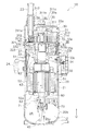
スクロール圧縮機10は、図1に示されるように、ケーシング20、圧縮機構30、駆動モータ50、駆動軸60、及び下部軸受70を主に有する。   As shown in FIG. 1, the scroll compressor 10 mainly includes a casing 20, a compression mechanism 30, a drive motor 50, a drive shaft 60, and a lower bearing 70.

スクロール圧縮機10の構成について以下に詳述する。なお、以下の説明では、方向や配置を説明するために、「上」、「下」等の表現を用いる場合があるが、特に断りの無い場合、図1中の矢印Uの方向を上とする。   The configuration of the scroll compressor 10 will be described in detail below. In the following description, expressions such as “upper” and “lower” may be used to describe the direction and arrangement, but the direction of the arrow U in FIG. To do.

(2)詳細構成
(2−1)ケーシング
スクロール圧縮機10は、縦長円筒状のケーシング20を有する。ケーシング20は、上下が開口した略円筒状の円筒部材21と、円筒部材21の上端及び下端にそれぞれ設けられた上蓋22a及び下蓋22bと、を有する(図1参照)。円筒部材21と、上蓋22a及び下蓋22bとは、気密を保つように溶接により固定される。
(2) Detailed Configuration (2-1) Casing The scroll compressor 10 has a vertically long cylindrical casing 20. The casing 20 includes a substantially cylindrical cylindrical member 21 that is open at the top and bottom, and an upper lid 22a and a lower lid 22b that are respectively provided at the upper end and the lower end of the cylindrical member 21 (see FIG. 1). The cylindrical member 21, and the upper lid 22a and the lower lid 22b are fixed by welding so as to keep airtightness.

ケーシング20には、圧縮機構30、駆動モータ50、駆動軸60及び下部軸受70を含むスクロール圧縮機10の構成機器が収容される。   The casing 20 accommodates components of the scroll compressor 10 including the compression mechanism 30, the drive motor 50, the drive shaft 60, and the lower bearing 70.

ケーシング20の下部には、下部油貯留空間26が形成される。下部油貯留空間26には、スクロール圧縮機10の摺動部を潤滑するための油O(冷凍機油)が溜められる。下部油貯留空間26は、後述する圧縮機構30のハウジング33より駆動モータ50側に形成される第1空間S1と連通する(図1参照)。   A lower oil storage space 26 is formed in the lower portion of the casing 20. In the lower oil storage space 26, oil O (refrigerator oil) for lubricating the sliding portion of the scroll compressor 10 is stored. The lower oil storage space 26 communicates with a first space S1 formed on the drive motor 50 side from a housing 33 of the compression mechanism 30 described later (see FIG. 1).

ケーシング20の上部には、圧縮機構30の圧縮対象である冷媒を吸入する吸入管23が、上蓋22aを貫通して設けられる(図1参照)。吸入管23の下端は、後述する圧縮機構30の固定スクロール31に接続される。吸入管23は、後述する圧縮機構30の圧縮室Scと連通する。吸入管23には、圧縮前の低圧の冷媒(冷凍サイクルにおける低圧の冷媒)が流れる。   In the upper part of the casing 20, a suction pipe 23 that sucks in a refrigerant to be compressed by the compression mechanism 30 is provided so as to penetrate the upper lid 22 a (see FIG. 1). The lower end of the suction pipe 23 is connected to a fixed scroll 31 of the compression mechanism 30 described later. The suction pipe 23 communicates with a compression chamber Sc of the compression mechanism 30 described later. A low-pressure refrigerant before compression (low-pressure refrigerant in the refrigeration cycle) flows through the suction pipe 23.

ケーシング20の円筒部材21の中間部には、ケーシング20外に吐出されるガス冷媒が通過する吐出管24が設けられる。吐出管24は、吐出管24のケーシング20内側の端部が、後述する圧縮機構30のハウジング33の下方に形成される第1空間S1に突き出すように配置される。吐出管24には、圧縮機構30により圧縮された高圧の冷媒(冷凍サイクルにおける高圧の冷媒)が流れる。   A discharge pipe 24 through which a gas refrigerant discharged to the outside of the casing 20 passes is provided at an intermediate portion of the cylindrical member 21 of the casing 20. The discharge pipe 24 is arranged so that the end of the discharge pipe 24 inside the casing 20 protrudes into a first space S1 formed below a housing 33 of the compression mechanism 30 described later. High-pressure refrigerant compressed by the compression mechanism 30 (high-pressure refrigerant in the refrigeration cycle) flows through the discharge pipe 24.

(2−2)圧縮機構
圧縮機構30は、図1に示されるように、主に、ハウジング33と、ハウジング33の上方に配置される固定スクロール31と、固定スクロール31と組み合わされて圧縮室Scを形成する可動スクロール32と、を有する。
(2-2) Compression Mechanism As shown in FIG. 1, the compression mechanism 30 is mainly combined with the housing 33, the fixed scroll 31 disposed above the housing 33, and the fixed scroll 31 to compress the compression chamber Sc. The movable scroll 32 is formed.

(2−2−1)固定スクロール
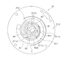
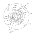
固定スクロール31は、図1及び図3に示されるように、円板状の固定側鏡板311と、固定側鏡板311の前面311a(下面)から突出する渦巻状の固定側ラップ312と、固定側ラップ312を囲む周縁部313と、を有する。
(2-2-1) Fixed Scroll As shown in FIG. 1 and FIG. 3, the fixed scroll 31 has a spiral shape protruding from a disk-shaped fixed side end plate 311 and a front surface 311 a (lower surface) of the fixed side end plate 311. The fixed-side wrap 312 and the peripheral edge 313 surrounding the fixed-side wrap 312.

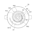
固定側鏡板311の前面311aには、段差が設けられている。言い換えれば、固定側鏡板311の前面311aは平坦ではない。そのため、固定側鏡板311の前面311aに対向する、後述する可動側ラップ322の先端322aと、固定側鏡板311の前面311aとの距離は、場所により異なる。固定側鏡板311間の前面311aに設けられた段差については後述する。   A step is provided on the front surface 311 a of the fixed side end plate 311. In other words, the front surface 311a of the fixed side end plate 311 is not flat. Therefore, the distance between the distal end 322a of the movable wrap 322, which will be described later, facing the front surface 311a of the fixed side end plate 311 and the front surface 311a of the fixed side end plate 311 varies depending on the location. The steps provided on the front surface 311a between the fixed side end plates 311 will be described later.

固定側鏡板311の中央部には、非円形形状の吐出ポート311bが、固定側鏡板311を厚さ方向に貫通して形成される(図1及び図3参照)。吐出ポート311bは、固定側ラップ312と後述する可動スクロール32の可動側ラップ322とが組み合わされて形成される圧縮室Scに連通する(図1参照)。   A non-circular discharge port 311b is formed in the center of the fixed side end plate 311 so as to penetrate the fixed side end plate 311 in the thickness direction (see FIGS. 1 and 3). The discharge port 311b communicates with a compression chamber Sc formed by combining a fixed wrap 312 and a movable wrap 322 of a movable scroll 32 described later (see FIG. 1).

固定側鏡板311の上面には、下方に凹むように凹部311c(図1参照)が形成されている。凹部311cは、固定側鏡板311の上面に、平面視において略円形状に形成されている。固定スクロール31の上面には、凹部311cを塞ぐように蓋体35がボルト35aにより固定されている(図1参照)。凹部311cと蓋体35との間には、吐出空間Saが形成される(図1参照)。   A recessed portion 311c (see FIG. 1) is formed on the upper surface of the fixed side end plate 311 so as to be recessed downward. The recess 311c is formed on the upper surface of the fixed side end plate 311 in a substantially circular shape in plan view. A lid 35 is fixed to the upper surface of the fixed scroll 31 with bolts 35a so as to close the recess 311c (see FIG. 1). A discharge space Sa is formed between the recess 311c and the lid 35 (see FIG. 1).

吐出空間Saは、吐出ポート311bを介して圧縮室Scと連通する(図1参照)。吐出空間Saには、圧縮室Scで圧縮された高圧の冷媒が吐出される。吐出空間Saは、固定スクロール31及びハウジング33にわたって形成された、図示しない冷媒経路と連通している。冷媒経路は、吐出空間Saとハウジング33の下方に形成される第1空間S1とを連通する経路である。圧縮室Scで圧縮された高圧の冷媒は、吐出ポート311bから上方の吐出空間Saに吐出され、固定スクロール31及びハウジング33に形成された図示しない冷媒経路を通過して第1空間S1へ流入する。高圧の冷媒が流入する第1空間S1は、ケーシング20の円筒部材21と後述する駆動モータ50のステータコア52との間に形成された経路(コアカット52a)等を介して、下部油貯留空間26と連通している(図1参照)。言い換えれば、下部油貯留空間26は、吐出空間Saと連通する高圧の空間である。   The discharge space Sa communicates with the compression chamber Sc via the discharge port 311b (see FIG. 1). The high-pressure refrigerant compressed in the compression chamber Sc is discharged into the discharge space Sa. The discharge space Sa communicates with a refrigerant path (not shown) formed over the fixed scroll 31 and the housing 33. The refrigerant path is a path that connects the discharge space Sa and the first space S <b> 1 formed below the housing 33. The high-pressure refrigerant compressed in the compression chamber Sc is discharged from the discharge port 311b to the upper discharge space Sa, passes through a refrigerant path (not shown) formed in the fixed scroll 31 and the housing 33, and flows into the first space S1. . The first space S1 into which the high-pressure refrigerant flows flows through the lower oil storage space 26 via a path (core cut 52a) formed between the cylindrical member 21 of the casing 20 and a stator core 52 of the drive motor 50 described later. (See FIG. 1). In other words, the lower oil storage space 26 is a high-pressure space that communicates with the discharge space Sa.

固定側鏡板311には、リリーフ穴311dが、固定側鏡板311を厚さ方向(上下方向)に貫通して形成されている(図2及び図3参照)。リリーフ穴311dを設け、圧縮室Sc内部の過圧縮ガスを吐出空間Saに逃がすことで、過圧縮損失が低減される。固定側鏡板311には、4箇所にリリーフ穴311dが形成されている(図3参照)。リリーフ穴311dは、圧縮室Sc、より具体的には後述する第1圧縮室Sc1及び第2圧縮室Sc2の両方の過圧縮損失を低減するために設けられている。リリーフ穴311dには、例えば特開2011−149376号公報に開示されているような構成を適用可能である。リリーフ穴311dの上方には、リリーフ弁311eが配置されている(図2参照)。   A relief hole 311d is formed in the fixed side end plate 311 so as to penetrate the fixed side end plate 311 in the thickness direction (vertical direction) (see FIGS. 2 and 3). By providing the relief hole 311d and letting the overcompressed gas inside the compression chamber Sc escape to the discharge space Sa, the overcompression loss is reduced. The fixed side end plate 311 has relief holes 311d at four locations (see FIG. 3). The relief hole 311d is provided in order to reduce the overcompression loss of the compression chamber Sc, more specifically, both the first compression chamber Sc1 and the second compression chamber Sc2 described later. For example, a configuration as disclosed in Japanese Patent Application Laid-Open No. 2011-149376 can be applied to the relief hole 311d. A relief valve 311e is disposed above the relief hole 311d (see FIG. 2).

固定側ラップ312は、渦巻き状に形成され、固定側鏡板311の前面311aから下方に延びる(図1参照)。固定側ラップ312の縦断面を側方から見た時に、固定側ラップ312の先端312aの高さ位置は一様である。なお、固定側ラップ312の先端312aの高さ位置が一様であるとは、固定側ラップ312の先端312aの高さ位置が実質的に一様である場合を含む。   The fixed side wrap 312 is formed in a spiral shape and extends downward from the front surface 311a of the fixed side end plate 311 (see FIG. 1). When the longitudinal section of the fixed side wrap 312 is viewed from the side, the height position of the tip 312a of the fixed side wrap 312 is uniform. In addition, that the height position of the front end 312a of the fixed side wrap 312 includes the case where the height position of the front end 312a of the fixed side wrap 312 is substantially uniform.

周縁部313は、厚肉のリング状に形成され、固定側ラップ312を取り囲むように配置される(図2及び図3参照)。   The peripheral edge 313 is formed in a thick ring shape and is disposed so as to surround the fixed side wrap 312 (see FIGS. 2 and 3).

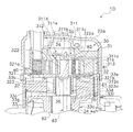
固定スクロール31の周縁部313及び固定側鏡板311には、後述するハウジング33に形成された第1油経路33eと連通する、第2油経路31aが形成されている(図2参照)。第2油経路31aには、第1油経路33eを通って油Oが供給される。第2油経路31aを流れた油Oは、固定側ラップ312に形成され、固定側ラップ312の先端312aに開口する第1給油穴81に供給される(図2参照)。   A second oil path 31a communicating with a first oil path 33e formed in the housing 33 described later is formed in the peripheral edge portion 313 of the fixed scroll 31 and the fixed side end plate 311 (see FIG. 2). Oil O is supplied to the second oil path 31a through the first oil path 33e. The oil O that has flowed through the second oil path 31a is formed in the fixed side wrap 312 and supplied to the first oil supply hole 81 that opens at the tip 312a of the fixed side wrap 312 (see FIG. 2).

第1給油穴81は、固定側ラップ312を、上下方向に貫通するように形成された穴である(図2参照)。第1給油穴81は、ここでは断面が円形状の穴であるが、第1給油穴81の断面形状は円形状に限定されるものではない。第1給油穴81の上端は、第2油経路31aに接続されている(図2参照)。第1給油穴81は、第2油経路31aと連通している。第1給油穴81は、第2油経路31aとの接続部から下方に延び、固定側ラップ312の先端312aで開口する。第1給油穴81の開口位置については後述する。   The first oil supply hole 81 is a hole formed so as to penetrate the fixed side wrap 312 in the vertical direction (see FIG. 2). The first oil supply hole 81 is a hole having a circular cross section here, but the cross sectional shape of the first oil supply hole 81 is not limited to a circular shape. The upper end of the 1st oil supply hole 81 is connected to the 2nd oil path | route 31a (refer FIG. 2). The first oil supply hole 81 communicates with the second oil path 31a. The first oil supply hole 81 extends downward from the connection portion with the second oil path 31 a and opens at the tip 312 a of the fixed side wrap 312. The opening position of the first oil supply hole 81 will be described later.

(2−2−2)可動スクロール
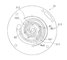
可動スクロール32は、図1及び図4に示されるように、略円板状の可動側鏡板321と、可動側鏡板321の前面321a(上面)から突出する渦巻状の可動側ラップ322と、可動側鏡板321の背面(下面)から突出する円筒状のピン軸受部323とを有する。
(2-2-2) Movable Scroll As shown in FIGS. 1 and 4, the movable scroll 32 includes a substantially disc-shaped movable side end plate 321 and a spiral projecting from the front surface 321 a (upper surface) of the movable side end plate 321. And a cylindrical pin bearing portion 323 projecting from the back surface (lower surface) of the movable side end plate 321.

可動側ラップ322は、可動側鏡板321の前面321aから上方に延びる。可動側ラップ322の縦断面を側方から見た時に、可動側ラップ322の先端322aの高さ位置は一様である。なお、可動側ラップ322の先端322aの高さ位置が一様であるとは、可動側ラップ322の先端322aの高さ位置が実質的に一様である場合を含む。   The movable side wrap 322 extends upward from the front surface 321 a of the movable side end plate 321. When the longitudinal section of the movable wrap 322 is viewed from the side, the height position of the tip 322a of the movable wrap 322 is uniform. In addition, that the height position of the front-end | tip 322a of the movable side wrap 322 includes the case where the height position of the front-end | tip 322a of the movable side wrap 322 is substantially uniform.

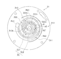
固定スクロール31の固定側ラップ312と、可動スクロール32の可動側ラップ322とは、固定側鏡板311の前面311aと可動側鏡板321の前面321aとが対向するように組み合わされ、隣接する固定側ラップ312と可動側ラップ322との間に圧縮室Scを形成する(図1参照)。なお、圧縮室Scには、可動スクロール32の可動側ラップ322の外周面322bと、固定スクロール31の固定側ラップ312の内周面312bと、によって囲まれて形成されるA室を含む(図6参照)。また、圧縮室Scには、可動スクロール32の可動側ラップ322の内周面322cと、固定スクロール31の固定側ラップ312の外周面312cと、によって囲まれて形成されるB室を含む(図6参照)。ここでは、A室を第1圧縮室Sc1と呼び、B室を第2圧縮室Sc2と呼ぶ(図6参照)。   The fixed-side wrap 312 of the fixed scroll 31 and the movable-side wrap 322 of the movable scroll 32 are combined so that the front surface 311a of the fixed-side end plate 311 and the front surface 321a of the movable-side end plate 321 face each other. A compression chamber Sc is formed between 312 and the movable wrap 322 (see FIG. 1). The compression chamber Sc includes a chamber A formed by being surrounded by the outer peripheral surface 322b of the movable side wrap 322 of the movable scroll 32 and the inner peripheral surface 312b of the fixed side wrap 312 of the fixed scroll 31 (see FIG. 6). Further, the compression chamber Sc includes a B chamber formed by being surrounded by the inner peripheral surface 322c of the movable side wrap 322 of the movable scroll 32 and the outer peripheral surface 312c of the fixed side wrap 312 of the fixed scroll 31 (see FIG. 6). Here, the A chamber is referred to as a first compression chamber Sc1, and the B chamber is referred to as a second compression chamber Sc2 (see FIG. 6).

可動側鏡板321の前面321aには、段差が設けられている。言い換えれば、可動側鏡板321の前面321aは平坦ではない。そのため、可動側鏡板321の前面321aに対向する固定側ラップ312の先端312aと、可動側鏡板321の前面321aとの距離は、場所によって異なる。可動側ラップ322間の前面321aに設けられた段差については後述する。   A step is provided on the front surface 321 a of the movable side end plate 321. In other words, the front surface 321a of the movable side end plate 321 is not flat. Therefore, the distance between the tip 312a of the fixed side wrap 312 facing the front surface 321a of the movable side end plate 321 and the front surface 321a of the movable end end plate 321 varies depending on the location. Steps provided on the front surface 321a between the movable wraps 322 will be described later.

可動スクロール32の可動側鏡板321には、可動側ラップ322に形成された第2給油穴82と連通する可動側鏡板内油経路321bが形成されている。   On the movable side end plate 321 of the movable scroll 32, a movable side end plate oil path 321 b communicating with the second oil supply hole 82 formed in the movable side wrap 322 is formed.

可動側鏡板内油経路321bは、可動側鏡板321の背面側に設けられたピン軸受部323内の、後述する駆動軸60のピン軸部61の上面と、可動側鏡板321の背面(下面)との間に形成される油連絡室36と連通している(図2参照)。油連絡室36には、後述するように駆動軸60の内部に形成された給油経路63を通って、下部油貯留空間26の油Oが流入する。給油経路63を通って油連絡室36に流入した、吐出空間Saと連通する下部油貯留空間26の油Oは、可動側鏡板内油経路321bを通過して、第2給油穴82に供給される。   The movable-side end-plate oil path 321b includes an upper surface of a pin shaft portion 61 of the drive shaft 60 (described later) and a back surface (lower-surface) of the movable-side end plate 321 in a pin bearing portion 323 provided on the back side of the movable-side end plate 321. (See FIG. 2). As will be described later, the oil O in the lower oil storage space 26 flows into the oil communication chamber 36 through an oil supply path 63 formed inside the drive shaft 60. The oil O in the lower oil storage space 26 that has flowed into the oil communication chamber 36 through the oil supply path 63 and communicated with the discharge space Sa passes through the movable side end plate oil path 321b and is supplied to the second oil supply hole 82. The

第2給油穴82は、可動側ラップ322を、上下方向に貫通するように形成された穴である(図2参照)。第2給油穴82は、ここでは断面が円形状の穴であるが、第2給油穴82の断面形状は円形状に限定されるものではない。第2給油穴82の下端は、可動側鏡板内油経路321bに接続されている(図2参照)。第2給油穴82は、可動側鏡板内油経路321bと連通している。第2給油穴82は、可動側鏡板内油経路321bとの接続部から上方に延び、可動側ラップ322の先端322aで開口する。第2給油穴82の開口位置については後述する。   The second oil supply hole 82 is a hole formed so as to penetrate the movable side wrap 322 in the vertical direction (see FIG. 2). Here, the second oil supply hole 82 is a hole having a circular cross section, but the cross sectional shape of the second oil supply hole 82 is not limited to a circular shape. The lower end of the second oil supply hole 82 is connected to the movable end plate oil passage 321b (see FIG. 2). The second oil supply hole 82 communicates with the movable side end plate oil passage 321b. The second oil supply hole 82 extends upward from the connecting portion with the movable side end-plate oil passage 321 b and opens at the tip 322 a of the movable side wrap 322. The opening position of the second oil supply hole 82 will be described later.

ピン軸受部323は、可動側鏡板321の背面から下方に延びる、円筒状の部分である(図1参照)。ピン軸受部323は、可動側鏡板321により円筒の上端が塞がれている。ピン軸受部323は、ハウジング33が形成する、後述するクランク室37の内部に収容される(図1参照)。可動スクロール32と駆動軸60とは、ピン軸受部323の内部に、後述する駆動軸60のピン軸部61が挿入されることで連結される。言い換えれば、可動スクロール32と駆動軸60とは、ピン軸受部323とピン軸部61とにより連結される。なお、ピン軸受部323の内部には、軸受メタル323aが嵌め込まれている(図2参照)。ピン軸受部323に挿入されるピン軸部61は、軸受メタル323aにより回転自在に支持される。ピン軸受部323において可動スクロール32が駆動軸60と連結されることで、駆動モータ50が駆動されると、駆動モータ50と連結された駆動軸60が回転し、可動スクロール32が駆動される。   The pin bearing portion 323 is a cylindrical portion that extends downward from the back surface of the movable side end plate 321 (see FIG. 1). The pin bearing portion 323 has its upper end closed by a movable side end plate 321. The pin bearing portion 323 is accommodated in a crank chamber 37 (described later) formed by the housing 33 (see FIG. 1). The movable scroll 32 and the drive shaft 60 are connected by inserting a pin shaft portion 61 of the drive shaft 60 described later into the pin bearing portion 323. In other words, the movable scroll 32 and the drive shaft 60 are connected by the pin bearing portion 323 and the pin shaft portion 61. A bearing metal 323a is fitted inside the pin bearing portion 323 (see FIG. 2). The pin shaft portion 61 inserted into the pin bearing portion 323 is rotatably supported by the bearing metal 323a. When the movable scroll 32 is coupled to the drive shaft 60 in the pin bearing portion 323, when the drive motor 50 is driven, the drive shaft 60 coupled to the drive motor 50 rotates and the movable scroll 32 is driven.

なお、ピン軸部61と軸受メタル323aとの間には、上下方向に延びるピン軸部油経路(図示せず)が形成される。ピン軸部油経路は、上端が油連絡室36に開口し、下端がクランク室37に開口している。ピン軸部油経路には、油連絡室36から油Oが流入する。ピン軸部油経路に流入した油Oは、ピン軸部61と軸受メタル323aとの摺動部へ供給される。ピン軸部61と軸受メタル323aとの摺動部を潤滑した油Oは、ハウジング33が形成するクランク室37に流入する。   A pin shaft oil path (not shown) extending in the vertical direction is formed between the pin shaft portion 61 and the bearing metal 323a. The pin shaft oil path has an upper end opened to the oil communication chamber 36 and a lower end opened to the crank chamber 37. Oil O flows from the oil communication chamber 36 into the pin shaft oil path. The oil O that has flowed into the pin shaft oil path is supplied to the sliding portion between the pin shaft portion 61 and the bearing metal 323a. The oil O that has lubricated the sliding portion between the pin shaft portion 61 and the bearing metal 323 a flows into the crank chamber 37 formed by the housing 33.

(2−2−3)ハウジング
ハウジング33は、円筒部材21に圧入され、その外周面において周方向の全体にわたって固定されている。ハウジング33は、固定スクロール31及び可動スクロール32に隣接して配置される。ここでは、ハウジング33は、固定スクロール31及び可動スクロール32の下方に配置される。ハウジング33と固定スクロール31とは、ハウジング33の上端面が、固定スクロール31の周縁部313の下面と対向するように配置され、図示しないボルト等により固定されている。
(2-2-3) Housing The housing 33 is press-fitted into the cylindrical member 21, and is fixed over the entire circumferential direction on the outer peripheral surface thereof. The housing 33 is disposed adjacent to the fixed scroll 31 and the movable scroll 32. Here, the housing 33 is disposed below the fixed scroll 31 and the movable scroll 32. The housing 33 and the fixed scroll 31 are disposed such that the upper end surface of the housing 33 faces the lower surface of the peripheral edge 313 of the fixed scroll 31 and is fixed by a bolt or the like (not shown).

ハウジング33には、上面中央部に凹むように配置される第1凹部33aと、第1凹部33aの下方に配置される上部軸受33cと、第1凹部33aを囲むように配置される第2凹部33bと、を有する。   The housing 33 includes a first recess 33a disposed so as to be recessed in the center of the upper surface, an upper bearing 33c disposed below the first recess 33a, and a second recess disposed so as to surround the first recess 33a. 33b.

第1凹部33aは、平面視において、円形状に形成されている。第1凹部33aは、その内部にクランク室37を形成する。言い換えれば、クランク室37は、第1凹部33aの内壁により囲まれた空間である。第1凹部33aの内部には、後述する駆動軸60のピン軸部61が内部に挿入された、可動スクロール32のピン軸受部323が配置される。言い換えれば、クランク室37は、可動スクロール32と駆動軸60との連結部が配置される空間である。   The first recess 33a is formed in a circular shape in plan view. The first recess 33a forms a crank chamber 37 therein. In other words, the crank chamber 37 is a space surrounded by the inner wall of the first recess 33a. A pin bearing portion 323 of the movable scroll 32 into which a pin shaft portion 61 of the drive shaft 60 described later is inserted is disposed inside the first recess 33a. In other words, the crank chamber 37 is a space in which a connecting portion between the movable scroll 32 and the drive shaft 60 is disposed.

上部軸受33cの内部には、軸受メタル34が設けられている。軸受メタル34は、ハウジング33の上部軸受33cに挿入された駆動軸60の主軸62を回転自在に軸支する。軸受メタル34の外側には、軸受メタル34の潤滑のために後述する駆動軸60に形成された給油経路63を介して供給された油Oを、クランク室37へと流すための、上部軸受部油経路(図示せず)が形成されている。   A bearing metal 34 is provided inside the upper bearing 33c. The bearing metal 34 rotatably supports the main shaft 62 of the drive shaft 60 inserted into the upper bearing 33 c of the housing 33. On the outside of the bearing metal 34, there is an upper bearing portion for flowing oil O supplied through an oil supply path 63 formed in a drive shaft 60, which will be described later, to lubricate the bearing metal 34 to the crank chamber 37. An oil path (not shown) is formed.

第2凹部33bは、ハウジング33の上面に、平面視において、第1凹部33aを取り囲むように形成される。第2凹部33bには、オルダム継手40が配置される。   The second recess 33b is formed on the upper surface of the housing 33 so as to surround the first recess 33a in plan view. The Oldham joint 40 is disposed in the second recess 33b.

また、ハウジング33には、ハウジング内油貯留空間33dが形成される(図2参照)。ハウジング内油貯留空間33dは、クランク室37と連通する。ハウジング内油貯留空間33dは、クランク室37の下方に配置される。ハウジング内油貯留空間33dは、上部軸受33cの上部に、軸受メタル34を囲むように円環状に形成された溝である。   The housing 33 is formed with an in-housing oil storage space 33d (see FIG. 2). The housing oil storage space 33 d communicates with the crank chamber 37. The in-housing oil storage space 33 d is disposed below the crank chamber 37. The oil storage space 33d in the housing is a groove formed in an annular shape so as to surround the bearing metal 34 in the upper part of the upper bearing 33c.

ハウジング内油貯留空間33dには、下部油貯留空間26から駆動軸60の内部の給油経路63を経て供給される油Oが貯留される。具体的には、ハウジング内油貯留空間33dの上方に配置されるクランク室37には、駆動軸60の内部に形成された給油経路63を流れ、可動スクロール32のピン軸受部323内に配置された軸受メタル323aと駆動軸60のピン軸部61との摺動部に供給された油Oが、図示しないピン軸部油経路を通過して流れこむ。また、ハウジング内油貯留空間33dの上方に配置されるクランク室37には、駆動軸60の内部に形成された給油経路63を流れ、上部軸受33cに配置された軸受メタル34と駆動軸60の主軸62との摺動部に供給された油Oが、図示しない上部軸受部油経路を通過して流れこむ。これらクランク室37に流入した油Oの一部が、ハウジング内油貯留空間33dに貯留される。   Oil O supplied from the lower oil storage space 26 via the oil supply path 63 inside the drive shaft 60 is stored in the oil storage space 33d in the housing. Specifically, the crank chamber 37 disposed above the oil storage space 33 d in the housing flows through the oil supply path 63 formed inside the drive shaft 60 and is disposed in the pin bearing portion 323 of the movable scroll 32. The oil O supplied to the sliding portion between the bearing metal 323a and the pin shaft portion 61 of the drive shaft 60 flows through a pin shaft portion oil path (not shown). In addition, the crank chamber 37 disposed above the oil storage space 33d in the housing flows through an oil supply path 63 formed inside the drive shaft 60, and the bearing metal 34 and the drive shaft 60 disposed in the upper bearing 33c. The oil O supplied to the sliding portion with the main shaft 62 flows through an upper bearing oil path (not shown). A part of the oil O flowing into the crank chamber 37 is stored in the oil storage space 33d in the housing.

なお、クランク室37に流入した油Oのうち、ハウジング内油貯留空間33dに流れ込まなかった油Oは、ハウジング33内に形成された排油経路33gを流れ、ケーシング20の円筒部材21と後述する駆動モータ50のステータコア52との間の経路(コアカット52a)を通過して、下部油貯留空間26へと戻される(図1及び図2参照)。   Of the oil O that has flowed into the crank chamber 37, the oil O that has not flown into the in-housing oil storage space 33d flows through the oil drain path 33g formed in the housing 33, and will be described later with the cylindrical member 21 of the casing 20. It passes through the path | route (core cut 52a) between the stator cores 52 of the drive motor 50, and is returned to the lower oil storage space 26 (refer FIG.1 and FIG.2).

また、ハウジング33には、ハウジング内油貯留空間33dと連通する第1油経路33eが形成されている。第1油経路33eは、固定スクロール31に形成された第2油経路31aの下端と連通する経路である。第1油経路33eには、流量制限部材33fが挿入されて固定されている。流量制限部材33fは、雄ねじ状に形成された部材である。流量制限部材33fは、第1油経路33e内に配置されることで、第1油経路33e内にスパイラル状の経路を形成する。第1油経路33e内に流量制限部材33fを配置し、第1油経路33eの流路を狭めることで、第1油経路33eを流れる油Oの圧力が調整される。なお、油Oの圧力を調整する必要が無い場合には、第1油経路33eに、流量制限部材33fが設けられなくてもよい。   The housing 33 is formed with a first oil path 33e communicating with the in-housing oil storage space 33d. The first oil path 33 e is a path that communicates with the lower end of the second oil path 31 a formed in the fixed scroll 31. A flow restricting member 33f is inserted and fixed in the first oil path 33e. The flow rate restricting member 33f is a member formed in a male screw shape. The flow restricting member 33f is disposed in the first oil path 33e, thereby forming a spiral path in the first oil path 33e. By disposing the flow restricting member 33f in the first oil path 33e and narrowing the flow path of the first oil path 33e, the pressure of the oil O flowing through the first oil path 33e is adjusted. When there is no need to adjust the pressure of the oil O, the flow rate restricting member 33f may not be provided in the first oil path 33e.

クランク室37に流れ込み、ハウジング内油貯留空間33dに溜まった高圧(略吐出圧)の油Oは、差圧により、ハウジング33に形成された第1油経路33e及び固定スクロール31に形成された第2油経路31aを経て、第1給油穴81に供給される。   The high-pressure (substantially discharge pressure) oil O that flows into the crank chamber 37 and accumulates in the oil storage space 33d in the housing is generated in the first oil passage 33e formed in the housing 33 and the first scroll 31 formed in the fixed scroll 31 by the differential pressure. The oil is supplied to the first oil supply hole 81 through the two oil path 31a.

(2−2−4)オルダム継手
オルダム継手40は、可動スクロール32の自転を防止するための部材である。オルダム継手40は、ハウジング33の第2凹部33bに配置されている。可動スクロール32に連結された駆動軸60が回転すると、可動スクロール32は、オルダム継手40の働きにより固定スクロール31に対して自転することなく公転し、圧縮室Sc(第1圧縮室Sc1及び第2圧縮室Sc2)内の冷媒が圧縮される。具体的には、圧縮室Scは、可動スクロール32の公転により固定側鏡板311及び可動側鏡板321の中心方向に移動するに連れ容積が減少し、それと共に圧縮室Sc内の圧力が上昇する。つまり、中央側の圧縮室Scの圧力は、周縁側の圧縮室Scよりも高圧になる。なお、冷媒は、圧力が上昇するに連れ、温度も上昇する。つまり、中央側の圧縮室Scの温度は、周縁側の圧縮室Scの温度よりも高温になる。
(2-2-4) Oldham Joint The Oldham Joint 40 is a member for preventing the movable scroll 32 from rotating. The Oldham coupling 40 is disposed in the second recess 33 b of the housing 33. When the drive shaft 60 connected to the movable scroll 32 rotates, the movable scroll 32 revolves without rotating with respect to the fixed scroll 31 by the action of the Oldham coupling 40, and the compression chamber Sc (the first compression chamber Sc1 and the second compression chamber Sc1). The refrigerant in the compression chamber Sc2) is compressed. Specifically, the volume of the compression chamber Sc decreases as the movable scroll 32 revolves in the center direction of the fixed-side end plate 311 and the movable-side end plate 321, and the pressure in the compression chamber Sc increases at the same time. That is, the pressure in the central compression chamber Sc is higher than that in the peripheral compression chamber Sc. Note that the temperature of the refrigerant increases as the pressure increases. That is, the temperature of the compression chamber Sc on the center side is higher than the temperature of the compression chamber Sc on the peripheral side.

(2−2−5)固定側ラップの先端と可動側鏡板との間の隙間について
固定側ラップ312の先端312aと可動側鏡板321との間の隙間について、以下に説明する。
(2-2-5) Gap between the distal end of the fixed side wrap and the movable side end plate The gap between the front end 312a of the fixed side wrap 312 and the movable side end plate 321 will be described below.

まず、隣接する可動側ラップ322に挟まれた可動側鏡板321の前面321a(歯底)に設けられた段差について以下に説明する。なお、ここでは、特記無き場合、可動側鏡板321全体の温度が一様であることを前提として以下の説明を行う。   First, the steps provided on the front surface 321a (tooth bottom) of the movable side end plate 321 sandwiched between the adjacent movable side wraps 322 will be described below. Here, the following description will be made on the assumption that the temperature of the entire movable side end plate 321 is uniform unless otherwise specified.

隣接する可動側ラップ322に挟まれた可動側鏡板321の前面321aは、可動側ラップ322の先端322aからの距離(上下方向の距離)の違いにより、3つの領域に分けられる(図4のB1,B2,B3参照)。ここでは、3つの領域を、外周側に配置されるものから順に、第1領域B1、第2領域B2、第3領域B3と呼ぶ(図4参照)。第1領域B1は、可動側ラップ322の先端322aからの距離が最小の領域である。第3領域B3は、可動側ラップ322の先端322aからの距離が最大の領域である。第2領域B2は、可動側ラップ322の先端322aからの距離が、第1領域B1における距離と第3領域B3における距離との中間の値である領域である。各領域B1,B2,B3内では、可動側ラップ322の先端322aから可動側鏡板321の前面321aまでの距離は同一である。第3領域B3は、可動側ラップ322の内周面322c側の巻き始めK(内周側の端部)を基準として、概ね0から2.5πまでの角度領域である(図4参照)。第2領域B2は、可動側ラップ322の内周面322c側の巻き始めKを基準として、概ね2.5πから4.5πまでの角度領域である(図4参照)。第1領域B1は、可動側ラップ322の内周面322c側の巻き始めKを基準として、概ね4.5πから、可動側ラップ322の内周面322c側の巻き終わりまでの角度領域である。   The front surface 321a of the movable side end plate 321 sandwiched between the adjacent movable side wraps 322 is divided into three regions depending on the distance (vertical direction distance) from the tip 322a of the movable side wrap 322 (B1 in FIG. 4). , B2, B3). Here, the three regions are referred to as a first region B1, a second region B2, and a third region B3 in order from the one arranged on the outer peripheral side (see FIG. 4). 1st area | region B1 is an area | region where the distance from the front-end | tip 322a of the movable side wrap 322 is the minimum. The third region B3 is a region having the maximum distance from the tip 322a of the movable side wrap 322. The second region B2 is a region in which the distance from the tip 322a of the movable wrap 322 is an intermediate value between the distance in the first region B1 and the distance in the third region B3. Within each region B1, B2, B3, the distance from the front end 322a of the movable side wrap 322 to the front surface 321a of the movable side end plate 321 is the same. The third region B3 is an angle region from approximately 0 to 2.5π with reference to the winding start K (end on the inner peripheral side) on the inner peripheral surface 322c side of the movable wrap 322 (see FIG. 4). The second region B2 is an angle region of approximately 2.5π to 4.5π with reference to the winding start K on the inner peripheral surface 322c side of the movable side wrap 322 (see FIG. 4). The first region B1 is an angle region from about 4.5π to the end of winding on the inner peripheral surface 322c side of the movable wrap 322 with reference to the winding start K on the inner peripheral surface 322c side of the movable wrap 322.

このように可動側鏡板321の前面321aに段差が形成されることで、図2のように、可動側鏡板321に対向する固定側ラップ312の先端312aと、可動側鏡板321との隙間は、常温下において、固定側ラップ312の外周側から内周側に広くなるように形成される。ここでは、固定スクロール31及び可動スクロール32が常温下に置かれ、なおかつ、固定スクロール31及び可動スクロール32の温度が全体に一様であることを前提としている。なお、図2は、説明のための図であって、図2中で示した隙間の大きさは、実際の固定側ラップ312の先端312aと、可動側鏡板321との隙間の実際の大きさを示したものではない。   By forming a step on the front surface 321a of the movable side end plate 321 in this way, the gap between the tip 312a of the fixed side wrap 312 facing the movable side end plate 321 and the movable end end plate 321 is as shown in FIG. Under normal temperature, it forms so that it may become wide from the outer peripheral side of the fixed side wrap 312 to an inner peripheral side. Here, it is assumed that the fixed scroll 31 and the movable scroll 32 are placed at room temperature, and that the temperatures of the fixed scroll 31 and the movable scroll 32 are uniform throughout. FIG. 2 is an explanatory diagram, and the size of the gap shown in FIG. 2 is the actual size of the gap between the actual tip 312a of the fixed side wrap 312 and the movable side end plate 321. It does not indicate.

このように、固定側ラップ312の先端312aと可動側鏡板321との隙間を、常温下において、固定側ラップ312の外周側から内周側に向かって広くなるように構成することで、R32系冷媒(R32を50重量%より多く含む冷媒)のような低圧側と高圧側との温度差が大きくなりやすい冷媒が使用される場合でも、固定側ラップ312の先端312aが、可動側鏡板321に接触することを防止できる。   In this way, by configuring the gap between the tip 312a of the fixed side wrap 312 and the movable side end plate 321 to increase from the outer peripheral side to the inner peripheral side of the fixed side wrap 312 at room temperature, the R32 system Even when a refrigerant, such as a refrigerant (a refrigerant containing more than 50% by weight of R32), is used which has a large temperature difference between the low pressure side and the high pressure side, the tip 312a of the fixed side wrap 312 is attached to the movable side end plate 321. Contact can be prevented.

(2−2−6)可動側ラップの先端と固定側鏡板との間の隙間について
可動側ラップ322の先端322aと固定側鏡板311との間の隙間について、以下に説明する。
(2-2-6) Gap between the distal end of the movable side wrap and the fixed side end plate The gap between the front end 322a of the movable side wrap 322 and the fixed side end plate 311 will be described below.

まず、隣接する固定側ラップ312に挟まれた固定側鏡板311の前面311a(歯底)に設けられた段差について以下に説明する。なお、ここでは、特記無き場合、固定側鏡板311全体の温度が一様であることを前提として以下の説明を行う。   First, the steps provided on the front surface 311a (tooth bottom) of the fixed side end plate 311 sandwiched between the adjacent fixed side wraps 312 will be described below. Here, the following description will be made on the assumption that the temperature of the entire fixed side end plate 311 is uniform unless otherwise specified.

隣接する固定側ラップ312に挟まれた固定側鏡板311の前面311aは、固定側ラップ312の先端312aからの距離(上下方向の距離)の違いにより、4つの領域に分けられる(図3のA1,A2,A3,A4参照)。ここでは、4つの領域を、外周側に配置されるものから順に、第1領域A1、第2領域A2、第3領域A3、第4領域A4と呼ぶ(図3参照)。第1領域A1は、固定側ラップ312の先端312aからの距離が最小の領域である。第4領域A4は、固定側ラップ312の先端312aからの距離が最大の領域である。第2領域B2は、固定側ラップ312の先端312aからの距離が、第1領域A1における距離と第3領域A3における距離との中間の値である領域である。第3領域A3は、固定側ラップ312の先端312aからの距離が、第2領域A2における距離と第4領域A4における距離との中間の値である領域である。各領域A1,A2,A3,A4内では、固定側ラップ312の先端312aから固定側鏡板311の前面311aまでの距離は同一である。第4領域A4は、固定側ラップ312の内周面312b側の巻き始めL(内周側の端部)を基準として、概ね0から2πまでの角度領域である(図3参照)。第3領域A3は、固定側ラップ312の内周面312b側の巻き始めLを基準として、概ね2πから3.5πまでの角度領域(図3参照)である。第2領域A2は、固定側ラップ312の内周面312b側の巻き始めLを基準として、概ね3.5πから4.5πまでの角度領域である(図3参照)。第1領域A1は、固定側ラップ312の内周面312b側の巻き始めLを基準として、概ね4.5πから、固定側ラップ312の内周面312b側の巻き終わり(外周側の端部)までの角度領域である。   The front surface 311a of the fixed-side end plate 311 sandwiched between the adjacent fixed-side wraps 312 is divided into four regions depending on the distance (vertical distance) from the tip 312a of the fixed-side wrap 312 (A1 in FIG. 3). , A2, A3, A4). Here, the four regions are referred to as a first region A1, a second region A2, a third region A3, and a fourth region A4 in order from those arranged on the outer peripheral side (see FIG. 3). The first region A1 is a region having a minimum distance from the tip 312a of the fixed side wrap 312. The fourth region A4 is a region having the maximum distance from the tip 312a of the fixed side wrap 312. The second region B2 is a region in which the distance from the tip 312a of the fixed side wrap 312 is an intermediate value between the distance in the first region A1 and the distance in the third region A3. The third area A3 is an area in which the distance from the tip 312a of the fixed side wrap 312 is an intermediate value between the distance in the second area A2 and the distance in the fourth area A4. Within each region A1, A2, A3, A4, the distance from the tip 312a of the fixed side wrap 312 to the front surface 311a of the fixed side end plate 311 is the same. The fourth region A4 is an angle region from about 0 to 2π with reference to the winding start L (end portion on the inner peripheral side) on the inner peripheral surface 312b side of the fixed side wrap 312 (see FIG. 3). The third region A3 is an angle region (see FIG. 3) of approximately 2π to 3.5π with reference to the winding start L on the inner peripheral surface 312b side of the fixed side wrap 312. The second region A2 is an angular region from approximately 3.5π to 4.5π with reference to the winding start L on the inner peripheral surface 312b side of the fixed side wrap 312 (see FIG. 3). The first region A1 is approximately 4.5π from the winding start L on the inner peripheral surface 312b side of the fixed side wrap 312 as a reference, and the winding end (end portion on the outer peripheral side) on the inner peripheral surface 312b side of the fixed side wrap 312. It is an angle area to.

このように固定側鏡板311の前面311aに段差が形成されることで、図2のように、固定側鏡板311に対向する可動側ラップ322の先端322aと、固定側鏡板311との隙間は、常温下において、可動側ラップ322の外周側から内周側に広くなるように形成される。ここでは、固定スクロール31及び可動スクロール32が常温下に置かれ、なおかつ、固定スクロール31及び可動スクロール32の温度が全体に一様である場合を前提としている。なお、図2は、説明のための図であって、図2中で示した隙間の大きさは、実際の可動側ラップ322の先端322aと、固定側鏡板311との隙間の実際の大きさを示したものではない。   By forming a step in the front surface 311a of the fixed side end plate 311 in this way, the gap between the tip 322a of the movable side wrap 322 facing the fixed side end plate 311 and the fixed end end plate 311 is as shown in FIG. Under normal temperature, it forms so that it may become wide from the outer peripheral side of the movable side wrap 322 to an inner peripheral side. Here, it is assumed that the fixed scroll 31 and the movable scroll 32 are placed at room temperature, and the temperature of the fixed scroll 31 and the movable scroll 32 is uniform throughout. 2 is an explanatory diagram, and the size of the gap shown in FIG. 2 is the actual size of the gap between the actual tip 322a of the movable side wrap 322 and the fixed side end plate 311. It does not indicate.

このように、可動側ラップ322の先端322aと固定側鏡板311との隙間を、常温下において、可動側ラップ322の外周側から内周側に向かって広くなるように構成することで、R32系冷媒のような低圧側と高圧側との温度差が大きくなりやすい冷媒が使用される場合でも、可動側ラップ322の先端322aが、固定側鏡板311に接触することを防止できる。   In this way, by configuring the gap between the distal end 322a of the movable wrap 322 and the fixed end panel 311 to increase from the outer peripheral side to the inner peripheral side of the movable wrap 322 at room temperature, the R32 system Even when a refrigerant such as a refrigerant that tends to have a large temperature difference between the low pressure side and the high pressure side is used, the tip 322a of the movable side wrap 322 can be prevented from contacting the fixed side end plate 311.

(2−2−7)第1給油穴及び第2給油穴の開口する位置について
第1給油穴81及び第2給油穴82の開口する位置について説明する。
(2-2-7) Positions at which the first oil supply hole and the second oil supply hole are opened The positions at which the first oil supply hole 81 and the second oil supply hole 82 are opened will be described.

まず、第1給油穴81の開口する位置について説明する。   First, the position where the first oil supply hole 81 opens will be described.

第1給油穴81は、固定側ラップ312の先端312aに開口する。第1給油穴81は、固定側ラップ312の先端312aと可動側鏡板321との隙間が最小となる第1隙間最小領域Ra0の領域外に開口する(図3参照)。第1隙間最小領域Ra0は、可動スクロール32が固定スクロール31に対して旋回する時に、常に可動側鏡板321の前面321aの第1領域B1と対向する領域である。第1隙間最小領域Ra0では、常温下においても、固定側ラップ312の先端312aと可動側鏡板321との隙間が比較的狭い。そのため、固定側ラップ312の先端312aと可動側鏡板321との間に存在する油Oの量が比較的少なくても、固定側ラップ312の先端312aと可動側鏡板321との隙間とを通過する冷媒の漏れが生じにくい。また、第1隙間最小領域Ra0は、可動側ラップ322の外周側の領域であるため、第1隙間最小領域Ra0の可動側ラップ322と隣接する圧縮室Sc内の圧力上昇は比較的小さく、固定側ラップ312の先端312aと可動側鏡板321との隙間を通過する冷媒の漏れが生じにくい。そのため、第1給油穴81は、第1隙間最小領域Ra0の領域外に開口するよう形成される。   The first oil supply hole 81 opens at the tip 312 a of the fixed side wrap 312. The first oil supply hole 81 opens outside the first gap minimum region Ra0 where the gap between the tip 312a of the fixed side wrap 312 and the movable side end plate 321 is minimized (see FIG. 3). The first gap minimum region Ra0 is a region that always faces the first region B1 of the front surface 321a of the movable side end plate 321 when the movable scroll 32 turns with respect to the fixed scroll 31. In the first gap minimum region Ra0, the gap between the tip 312a of the fixed side wrap 312 and the movable side end plate 321 is relatively narrow even at room temperature. Therefore, even if the amount of oil O existing between the tip 312a of the fixed side wrap 312 and the movable side end plate 321 is relatively small, it passes through the gap between the tip 312a of the fixed side wrap 312 and the movable side end plate 321. Refrigerant leakage is unlikely to occur. Further, since the first gap minimum region Ra0 is a region on the outer peripheral side of the movable side wrap 322, the pressure increase in the compression chamber Sc adjacent to the movable side wrap 322 of the first gap minimum region Ra0 is relatively small and fixed. Leakage of the refrigerant passing through the gap between the tip 312a of the side wrap 312 and the movable side end plate 321 hardly occurs. Therefore, the first oil supply hole 81 is formed so as to open outside the region of the first gap minimum region Ra0.

また、第1給油穴81は、固定側ラップ312の先端312aの、吐出空間Saとは直接連通しない領域において開口することが好ましい。言い換えれば、第1給油穴81は、固定側ラップ312の先端312aであって、固定側ラップ312の、吐出ポート311bを介して吐出空間Saと直接連通する圧縮室Scと隣接しない領域において開口することが好ましい。第1給油穴81への給油は、ハウジング内油貯留空間33dと圧縮室Scとの圧力差によりなされるため、吐出空間Saとは直接連通しない領域に第1給油穴81を開口させることで、第1給油穴81への給油量を十分確保することが容易になる。このような観点から、第1給油穴81は、固定側ラップ312の先端312aの、固定側ラップ312の内周側の巻き始めLを基準として、2π以上の角度領域で開口することが好ましい。2π以上の角度領域で第1給油穴81が開口するようにすれば、第1圧縮室Sc1及び第2圧縮室Sc2のいずれが吐出ポート311bを介して吐出空間Saと連通する場合にも、第1給油穴81の開口と、吐出空間Saとが直接連通することがない。   Further, the first oil supply hole 81 is preferably opened in a region of the tip 312a of the fixed side wrap 312 that is not in direct communication with the discharge space Sa. In other words, the first oil supply hole 81 is the tip 312a of the fixed side wrap 312 and opens in a region of the fixed side wrap 312 that is not adjacent to the compression chamber Sc that directly communicates with the discharge space Sa via the discharge port 311b. It is preferable. Since the oil supply to the first oil supply hole 81 is made by a pressure difference between the oil storage space 33d in the housing and the compression chamber Sc, by opening the first oil supply hole 81 in a region not directly communicating with the discharge space Sa, It becomes easy to ensure a sufficient amount of oil supplied to the first oil supply hole 81. From such a viewpoint, it is preferable that the first oil supply hole 81 is opened in an angle region of 2π or more with reference to the winding start L on the inner peripheral side of the fixed side wrap 312 at the tip 312a of the fixed side wrap 312. If the first oil supply hole 81 is opened in an angle region of 2π or more, the first compression chamber Sc1 and the second compression chamber Sc2 can communicate with the discharge space Sa via the discharge port 311b. The opening of the 1 oil supply hole 81 and the discharge space Sa do not communicate directly.

さらに、第1給油穴81は、固定側ラップ312の先端312aの、吐出空間Saとは直接連通しない領域内で、常温下で、固定側ラップ312の先端312aと可動側鏡板321との隙間が最大となる領域に開口することが好ましい。吐出空間Saとは直接連通しない領域の中でも、特に固定側ラップ312の先端312aと可動側鏡板321との隙間が最大となる領域に第1給油穴81が形成されることで、固定側ラップ312の先端312aと可動側鏡板321との隙間を通過する冷媒の漏れが特に問題となりやすい領域に、油Oを供給することができる。例えば、ここでは、図5のように、吐出空間Saとは直接連通しない領域(固定側ラップ312の内周側の巻き始めLを基準として、2π以上の角度領域)の中でも、スクロール圧縮機10の運転中に、可動側鏡板321の前面321aの第2領域B2と少なくとも一時的に対向する領域に開口するよう、第1給油穴81が形成されることが好ましい。より好ましくは、吐出空間Saとは直接連通しない領域の中でも、スクロール圧縮機10の運転中に、可動側鏡板321の前面321aの第2領域B2と常に対向する領域に開口するよう、第1給油穴81が形成される。数字で表せば、図3のように、第1給油穴81は、2π以上2.5π未満の角度領域Ra1(図3における固定側ラップ312上のハッチングの付された領域)で開口することが好ましい。さらに好ましくは、第1給油穴81は、吐出空間Saとは直接連通しない領域の中でも出来る限り内周側に形成されることが好ましい。言い換えれば、第1給油穴81は、固定側ラップ312の内周側の巻き始めLを基準として2πの角度の近傍で開口するように形成されることが好ましい。   Further, the first oil supply hole 81 has a gap between the tip 312a of the fixed side wrap 312 and the movable side end plate 321 at room temperature in an area where the tip 312a of the fixed side wrap 312 does not directly communicate with the discharge space Sa. It is preferable to open to the maximum region. Among the regions that are not in direct communication with the discharge space Sa, in particular, the first oil supply hole 81 is formed in a region where the gap between the tip 312a of the fixed side wrap 312 and the movable side end plate 321 is maximum, so that the fixed side wrap 312 is formed. The oil O can be supplied to a region where leakage of the refrigerant passing through the gap between the tip 312a of the first plate 312 and the movable side end plate 321 is particularly problematic. For example, as shown in FIG. 5, the scroll compressor 10 is included in a region that does not directly communicate with the discharge space Sa (an angle region of 2π or more with respect to the winding start L on the inner peripheral side of the fixed side wrap 312). During the operation, the first oil supply hole 81 is preferably formed so as to open to a region at least temporarily facing the second region B2 of the front surface 321a of the movable side end plate 321. More preferably, the first oil supply so as to open to the region always facing the second region B2 of the front surface 321a of the movable side end plate 321 during the operation of the scroll compressor 10 among the regions not directly communicating with the discharge space Sa. A hole 81 is formed. In numerical terms, as shown in FIG. 3, the first oil supply hole 81 may open in an angle region Ra1 (a hatched region on the fixed side wrap 312 in FIG. 3) of 2π or more and less than 2.5π. preferable. More preferably, the first oil supply hole 81 is preferably formed on the inner peripheral side as much as possible in a region that does not directly communicate with the discharge space Sa. In other words, the first oil supply hole 81 is preferably formed so as to open in the vicinity of an angle of 2π with reference to the winding start L on the inner peripheral side of the fixed side wrap 312.

次に、第2給油穴82の開口する位置について説明する。   Next, the position where the second oil supply hole 82 opens will be described.

第2給油穴82は、可動側ラップ322の先端322aに開口する。第2給油穴82は、可動側ラップ322の先端322aと固定側鏡板311との隙間が最小となる第2隙間最小領域Rb0の領域外に開口する(図4参照)。第2隙間最小領域Rb0は、可動スクロール32が固定スクロール31に対して旋回する時に、常に固定側鏡板311の前面311aの第1領域A1と対向する領域である。第2隙間最小領域Rb0では、常温下においても、可動側ラップ322の先端322aと固定側鏡板311との隙間が比較的狭い。そのため、可動側ラップ322の先端322aと固定側鏡板311との間に存在する油Oの量が比較的少なくても、可動側ラップ322の先端322aと固定側鏡板311との隙間とを通過する冷媒の漏れが生じにくい。また、第2隙間最小領域Rb0は、可動側ラップ322の外周側の領域であるため、第2隙間最小領域Rb0の可動側ラップ322と隣接する圧縮室Sc内の圧力上昇は比較的小さく、可動側ラップ322の先端322aと固定側鏡板311との隙間を通過する冷媒の漏れが生じにくい。そのため、第2給油穴82は、第2隙間最小領域Rb0の領域外に開口するよう形成される。   The second oil supply hole 82 opens at the tip 322 a of the movable side wrap 322. The second oil supply hole 82 opens outside the second gap minimum region Rb0 where the gap between the tip 322a of the movable side wrap 322 and the fixed side end plate 311 is minimized (see FIG. 4). The second minimum gap region Rb0 is a region that always faces the first region A1 of the front surface 311a of the fixed side end plate 311 when the movable scroll 32 turns with respect to the fixed scroll 31. In the second minimum gap region Rb0, the gap between the distal end 322a of the movable side wrap 322 and the fixed side end plate 311 is relatively narrow even at room temperature. Therefore, even if the amount of oil O existing between the tip 322a of the movable side wrap 322 and the fixed side end plate 311 is relatively small, it passes through the gap between the tip 322a of the movable side wrap 322 and the fixed side end plate 311. Refrigerant leakage is unlikely to occur. Further, since the second minimum gap region Rb0 is an outer peripheral region of the movable side wrap 322, the pressure increase in the compression chamber Sc adjacent to the movable side wrap 322 of the second minimum gap region Rb0 is relatively small and movable. Leakage of the refrigerant passing through the gap between the tip 322a of the side wrap 322 and the fixed side end plate 311 is unlikely to occur. Therefore, the second oil supply hole 82 is formed so as to open outside the second gap minimum region Rb0.

また、第2給油穴82は、可動側ラップ322の先端322aの、吐出空間Saとは直接連通しない領域において開口することが好ましい。言い換えれば、第2給油穴82は、可動側ラップ322の先端322aであって、可動側ラップ322の、吐出ポート311bを介して吐出空間Saと直接連通する圧縮室Scと隣接しない領域において開口することが好ましい。第2給油穴82への給油は、下部油貯留空間26と圧縮室Scとの圧力差によりなされるため、吐出空間Saとは直接連通しない領域に第2給油穴82を開口させることで、第2給油穴82への給油量を十分確保することが容易になる。このような観点から、第2給油穴82は、可動側ラップ322の先端322aの、可動側ラップ322の内周側の巻き始めKを基準として、3π以上の角度領域で開口することが好ましい。3π以上の角度領域で第2給油穴82が開口するようにすれば、第1圧縮室Sc1及び第2圧縮室Sc2のいずれが吐出ポート311bを介して吐出空間Saと連通する場合にも、第2給油穴82の開口と、吐出空間Saとが直接連通することがない。   Further, the second oil supply hole 82 is preferably opened in a region of the tip 322a of the movable side wrap 322 that does not directly communicate with the discharge space Sa. In other words, the second oil supply hole 82 is the tip 322a of the movable side wrap 322 and opens in a region that is not adjacent to the compression chamber Sc that communicates directly with the discharge space Sa via the discharge port 311b of the movable side wrap 322. It is preferable. Since the oil supply to the second oil supply hole 82 is made by the pressure difference between the lower oil storage space 26 and the compression chamber Sc, the second oil supply hole 82 is opened in an area that is not in direct communication with the discharge space Sa. 2 It becomes easy to ensure a sufficient amount of oil supplied to the oil supply hole 82. From such a viewpoint, it is preferable that the second oil supply hole 82 is opened in an angle region of 3π or more with reference to the winding start K of the distal end 322a of the movable side wrap 322 on the inner peripheral side of the movable side wrap 322. If the second oil supply hole 82 is opened in an angular region of 3π or more, the first compression chamber Sc1 and the second compression chamber Sc2 can be connected to the discharge space Sa via the discharge port 311b. 2 The opening of the oil supply hole 82 and the discharge space Sa do not directly communicate with each other.

さらに、第2給油穴82は、可動側ラップ322の先端322aの、吐出空間Saとは直接連通しない領域内で、常温下で、可動側ラップ322の先端322aと固定側鏡板311との隙間が最大となる領域に開口することが好ましい。吐出空間Saとは直接連通しない領域の中で、特に可動側ラップ322の先端322aと可動側鏡板321との隙間が最大となる領域に第2給油穴82が形成されることで、可動側ラップ322の先端322aと固定側鏡板311との隙間を通過する冷媒の漏れが特に問題となりやすい領域に、油Oを供給することができる。例えば、ここでは、図6のように、吐出空間Saとは直接連通しない領域(可動側ラップ322の内周側の巻き始めKを基準として、3π以上の角度領域)の中でも、スクロール圧縮機10の運転中に、固定側鏡板311の前面311aの第2領域A2と少なくとも一時的に対向する領域に開口するよう、第2給油穴82が形成されることが好ましい。より好ましくは、吐出空間Saとは直接連通しない領域の中でも、スクロール圧縮機10の運転中に、固定側鏡板311の前面311aの第2領域A2と常に対向する領域に開口するよう、第2給油穴82が形成される。数字で表せば、図4のように、第2給油穴82は、3π以上3.5π未満の第1角度領域Rb1(図4における可動側ラップ322上のハッチングの付された領域)で開口することが好ましい(図3参照)。さらに好ましくは、第2給油穴82は、吐出空間Saとは直接連通しない領域の中でも出来る限り内周側に形成されることが好ましい。言い換えれば、第2給油穴82は、可動側ラップ322の内周側の巻き始めKを基準として3πの角度の近傍に開口するように形成されることが好ましい。   Further, the second oil supply hole 82 has a gap between the tip 322a of the movable side wrap 322 and the fixed side end plate 311 at room temperature in a region where the tip 322a of the movable side wrap 322 does not directly communicate with the discharge space Sa. It is preferable to open to the maximum region. The second oil supply hole 82 is formed in the region where the gap between the tip 322a of the movable side wrap 322 and the movable side end plate 321 is the largest in the region not directly communicating with the discharge space Sa. Oil O can be supplied to a region where leakage of the refrigerant passing through the gap between the tip 322a of the 322 and the fixed side end plate 311 is particularly problematic. For example, as shown in FIG. 6, the scroll compressor 10 is also included in a region that does not directly communicate with the discharge space Sa (an angle region of 3π or more with respect to the winding start K on the inner peripheral side of the movable wrap 322). During the operation, the second oil supply hole 82 is preferably formed so as to open to a region at least temporarily facing the second region A2 of the front surface 311a of the fixed-side end plate 311. More preferably, among the regions that are not in direct communication with the discharge space Sa, during the operation of the scroll compressor 10, the second oil supply is performed so as to open to a region that always faces the second region A2 of the front surface 311a of the fixed-side end plate 311. A hole 82 is formed. In terms of numbers, as shown in FIG. 4, the second oil supply hole 82 opens in a first angle region Rb1 (a hatched region on the movable side wrap 322 in FIG. 4) of 3π or more and less than 3.5π. It is preferable (see FIG. 3). More preferably, the second oil supply hole 82 is preferably formed on the inner peripheral side as much as possible in a region that does not directly communicate with the discharge space Sa. In other words, the second oil supply hole 82 is preferably formed so as to open in the vicinity of an angle of 3π with reference to the winding start K on the inner peripheral side of the movable side wrap 322.

(2−3)駆動モータ
駆動モータ50は、可動スクロール32を固定スクロール31に対して旋回させる駆動部の一例である。駆動モータ50は、円筒部材21の内壁面に固定された環状のステータ51と、ステータ51の内側に僅かな隙間(エアギャップ)を空けて回転自在に収容されたロータ53とを有する(図1参照)。
(2-3) Drive Motor The drive motor 50 is an example of a drive unit that turns the movable scroll 32 relative to the fixed scroll 31. The drive motor 50 includes an annular stator 51 fixed to the inner wall surface of the cylindrical member 21, and a rotor 53 that is rotatably accommodated with a slight gap (air gap) inside the stator 51 (FIG. 1). reference).

ステータ51は、筒状のステータコア52と、ステータコア52に巻き回される巻線(図示せず)とを有する。ステータコア52の外周面には、上下方向に延びるコアカット52aが形成されている(図1参照)。クランク室37から排油経路33gに流入した油Oは、コアカット52aを介して下部油貯留空間26に戻される。   The stator 51 has a cylindrical stator core 52 and windings (not shown) wound around the stator core 52. A core cut 52a extending in the vertical direction is formed on the outer peripheral surface of the stator core 52 (see FIG. 1). The oil O that has flowed into the oil discharge path 33g from the crank chamber 37 is returned to the lower oil storage space 26 through the core cut 52a.

ロータ53は、円筒状の部材で、内部に駆動軸60が挿通されている。ロータ53は、駆動軸60を介して可動スクロール32と連結されている。ロータ53が回転することで、可動スクロール32が固定スクロール31に対して旋回する。   The rotor 53 is a cylindrical member, and the drive shaft 60 is inserted therein. The rotor 53 is connected to the movable scroll 32 via the drive shaft 60. As the rotor 53 rotates, the movable scroll 32 rotates with respect to the fixed scroll 31.

(2−4)駆動軸
駆動軸60は、円筒部材21の軸心に沿って上下方向に延びるように配置され、駆動モータ50のロータ53と、圧縮機構30の可動スクロール32とを連結する。駆動軸60は、駆動モータ50の駆動力を可動スクロール32に伝達する。
(2-4) Drive shaft The drive shaft 60 is disposed so as to extend in the vertical direction along the axial center of the cylindrical member 21, and connects the rotor 53 of the drive motor 50 and the movable scroll 32 of the compression mechanism 30. The drive shaft 60 transmits the driving force of the drive motor 50 to the movable scroll 32.

駆動軸60は、円筒部材21の軸心と中心軸が一致する主軸62と、円筒部材21の軸心(主軸62の中心軸)に対して偏心したピン軸部61とを有する(図1参照)。駆動軸60の内部には、給油経路63が形成されている(図1参照)。   The drive shaft 60 has a main shaft 62 whose central axis coincides with the central axis of the cylindrical member 21, and a pin shaft portion 61 that is eccentric with respect to the axial center of the cylindrical member 21 (the central axis of the main shaft 62) (see FIG. 1). ). An oil supply path 63 is formed inside the drive shaft 60 (see FIG. 1).

ピン軸部61は、主軸62の上方に配置される。ピン軸部61は、可動スクロール32のピン軸受部323に連結される。   The pin shaft portion 61 is disposed above the main shaft 62. The pin shaft portion 61 is connected to the pin bearing portion 323 of the movable scroll 32.

主軸62は、ハウジング33に設けられた上部軸受33cに配置された軸受メタル34、及び、後述する下部軸受70に配置された軸受メタル71により、回転自在に軸支される。また、主軸62は、上部軸受33cと下部軸受70との間で、駆動モータ50のロータ53と連結される。主軸62は、上下方向に延びる鉛直軸周りに回転する。   The main shaft 62 is rotatably supported by a bearing metal 34 disposed in an upper bearing 33 c provided in the housing 33 and a bearing metal 71 disposed in a lower bearing 70 described later. The main shaft 62 is connected to the rotor 53 of the drive motor 50 between the upper bearing 33 c and the lower bearing 70. The main shaft 62 rotates around a vertical axis extending in the vertical direction.

給油経路63は、スクロール圧縮機10の摺動部に油Oを供給するための、油Oの流路である。給油経路63は、駆動軸60の軸方向に、駆動軸60の下端から上端まで延び、駆動軸60の上下の端部で開口する。   The oil supply path 63 is a flow path of the oil O for supplying the oil O to the sliding portion of the scroll compressor 10. The oil supply path 63 extends from the lower end to the upper end of the drive shaft 60 in the axial direction of the drive shaft 60 and opens at the upper and lower ends of the drive shaft 60.

駆動軸60の下端には、給油ポンプ65が取り付けられている(図1参照)。給油ポンプ65は、トロコイドポンプ等の容積型ポンプである。給油ポンプ65の油Oの吸入口65aの下端は、下部油貯留空間26内に配置されている(図1参照)。給油ポンプ65の吐出口は、給油経路63の下端と接続されている。駆動軸60が回転すると、給油ポンプ65が駆動され、油Oが吸入口65aを通って下部油貯留空間26から吸い上げられ、給油経路63に流入する。給油経路63に流入した油Oは、駆動軸60内を上方に流れる。給油経路63を流れる油Oの一部は、給油経路63の上端側の開口まで運ばれる。また、給油経路63を流れる油Oの一部は、駆動軸60の内部に形成された図示しない経路を通って、上部軸受33c及び下部軸受70と、駆動軸60との摺動部に供給される。   An oil supply pump 65 is attached to the lower end of the drive shaft 60 (see FIG. 1). The oil supply pump 65 is a positive displacement pump such as a trochoid pump. The lower end of the oil O suction port 65a of the oil supply pump 65 is disposed in the lower oil storage space 26 (see FIG. 1). The discharge port of the oil supply pump 65 is connected to the lower end of the oil supply path 63. When the drive shaft 60 rotates, the oil supply pump 65 is driven, and the oil O is sucked up from the lower oil storage space 26 through the suction port 65a and flows into the oil supply path 63. The oil O that has flowed into the oil supply path 63 flows upward in the drive shaft 60. Part of the oil O flowing through the oil supply path 63 is carried to the opening on the upper end side of the oil supply path 63. Part of the oil O flowing through the oil supply path 63 is supplied to a sliding portion between the upper bearing 33 c and the lower bearing 70 and the drive shaft 60 through a path (not shown) formed in the drive shaft 60. The

(2−5)下部軸受
下部軸受70(図1参照)は、駆動モータ50の下方に配置される。下部軸受70は、ケーシング20の円筒部材21と固定されている。下部軸受70は、その内部に収容された軸受メタル71を含む(図1参照)。軸受メタル71は、駆動軸60の主軸62の下部側を回転自在に軸支する。
(2-5) Lower Bearing The lower bearing 70 (see FIG. 1) is disposed below the drive motor 50. The lower bearing 70 is fixed to the cylindrical member 21 of the casing 20. The lower bearing 70 includes a bearing metal 71 accommodated therein (see FIG. 1). The bearing metal 71 rotatably supports the lower side of the main shaft 62 of the drive shaft 60.

(3)スクロール圧縮機の動作
スクロール圧縮機10の動作について説明する。
(3) Operation of Scroll Compressor The operation of the scroll compressor 10 will be described.

(3−1)圧縮動作
駆動モータ50が駆動されると、ロータ53が回転し、ロータ53と連結された駆動軸60も回転する。駆動軸60が回転すると、オルダム継手40の働きにより、可動スクロール32は自転せずに、固定スクロール31に対して公転する。そして、低圧の(吸入圧の)冷媒が、吸入管23を通ってケーシング20内に吸引される。より具体的には、低圧の冷媒が、吸入管23から圧縮室Scへ、圧縮室Scの周縁側から吸引される。可動スクロール32が公転するのに従い、吸入管23と圧縮室Scとは連通しなくなり、圧縮室Scの容積が減少するのに伴って、圧縮室Scの圧力が上昇する。冷媒は、周縁側の圧縮室Scから、中央側の圧縮室Scへ移動するにつれ圧力が上昇し、最終的に高圧(吐出圧)となる。圧縮機構30によって圧縮された高圧の冷媒は、固定側鏡板311の中央付近に位置する吐出ポート311bから吐出空間Saに吐出される。吐出空間Saの高圧の冷媒は、固定スクロール31及びハウジング33に形成された図示しない冷媒経路を通過して、ハウジング33の下方の第1空間S1へ流入する。
(3-1) Compression Operation When the drive motor 50 is driven, the rotor 53 rotates and the drive shaft 60 connected to the rotor 53 also rotates. When the drive shaft 60 rotates, the movable scroll 32 revolves with respect to the fixed scroll 31 without rotating due to the action of the Oldham coupling 40. Then, the low-pressure (suction pressure) refrigerant is sucked into the casing 20 through the suction pipe 23. More specifically, the low-pressure refrigerant is sucked from the suction pipe 23 to the compression chamber Sc from the peripheral side of the compression chamber Sc. As the movable scroll 32 revolves, the suction pipe 23 and the compression chamber Sc are not in communication with each other, and the pressure in the compression chamber Sc increases as the volume of the compression chamber Sc decreases. As the refrigerant moves from the compression chamber Sc on the peripheral side to the compression chamber Sc on the center side, the pressure increases and finally becomes a high pressure (discharge pressure). The high-pressure refrigerant compressed by the compression mechanism 30 is discharged into the discharge space Sa from the discharge port 311b located near the center of the fixed side end plate 311. The high-pressure refrigerant in the discharge space Sa passes through a refrigerant path (not shown) formed in the fixed scroll 31 and the housing 33 and flows into the first space S <b> 1 below the housing 33.

(3−2)給油動作
駆動軸60が回転すると、給油ポンプ65が駆動されて油Oが下部油貯留空間26から吸い上げられ、給油経路63を駆動軸60の上端の開口まで上方に流れ、駆動軸60の上方に形成された油連絡室36に流出する。油連絡室36まで運ばれた油Oの一部は、可動スクロール32の可動側鏡板321の内部に形成された可動側鏡板内油経路321bを通って、第2給油穴82に供給される。また、油連絡室36まで運ばれた油Oの一部は、図示しないピン軸部油経路を通って、ピン軸受部323の内部に配置された軸受メタル323aと駆動軸60のピン軸部61との摺動部に供給される。軸受メタル323aとピン軸部61との摺動部に供給された油Oは、ピン軸部油経路を通ってクランク室37に流入する。また、給油経路63を運ばれた油Oの一部は、主軸62に形成された図示しない経路を通って、上部軸受33cの軸受メタル34と駆動軸60の主軸62との摺動部に供給される。軸受メタル34と主軸62との摺動部を潤滑した油Oは、ハウジング33に形成された上部軸受部油経路(図示せず)を通ってクランク室37に流入する。クランク室37に流入した油Oの一部は、ハウジング33に形成された排油経路33gを通過し、駆動モータ50のステータコア52と円筒部材21との間に形成された経路(コアカット52a)を通過して下部油貯留空間26へと戻る。また、クランク室37の内部に流入した油Oの一部は、クランク室37と連通するハウジング内油貯留空間33d内に溜められる。ハウジング内油貯留空間33d内に溜まった油Oは、差圧により、ハウジング33に形成された第1油経路33e及び固定スクロール31に形成された第2油経路31aを通って、第1給油穴81に供給される。また、給油経路63を運ばれた油Oの一部は、主軸62に形成された図示しない経路を通って、下部軸受70に設けられた軸受メタル71と駆動軸60の主軸62との摺動部に供給される。軸受メタル71と主軸62との動部を潤滑した油Oは、下部油貯留空間26へと戻る。
(3-2) Oil Supply Operation When the drive shaft 60 rotates, the oil pump 65 is driven to suck up the oil O from the lower oil storage space 26, and flows upward through the oil supply path 63 to the opening at the upper end of the drive shaft 60. It flows out to the oil communication chamber 36 formed above the shaft 60. Part of the oil O transported to the oil communication chamber 36 is supplied to the second oil supply hole 82 through the movable side end plate oil path 321 b formed inside the movable side end plate 321 of the movable scroll 32. Part of the oil O transported to the oil communication chamber 36 passes through a pin shaft oil path (not shown), and the bearing metal 323 a disposed inside the pin bearing portion 323 and the pin shaft portion 61 of the drive shaft 60. And is supplied to the sliding part. The oil O supplied to the sliding portion between the bearing metal 323a and the pin shaft portion 61 flows into the crank chamber 37 through the pin shaft portion oil path. Further, a part of the oil O conveyed through the oil supply path 63 is supplied to a sliding portion between the bearing metal 34 of the upper bearing 33 c and the main shaft 62 of the drive shaft 60 through a path (not shown) formed in the main shaft 62. Is done. The oil O that has lubricated the sliding portion between the bearing metal 34 and the main shaft 62 flows into the crank chamber 37 through an upper bearing portion oil path (not shown) formed in the housing 33. Part of the oil O that has flowed into the crank chamber 37 passes through an oil discharge path 33g formed in the housing 33, and a path formed between the stator core 52 and the cylindrical member 21 of the drive motor 50 (core cut 52a). And return to the lower oil storage space 26. A part of the oil O that has flowed into the crank chamber 37 is stored in an in-housing oil storage space 33 d that communicates with the crank chamber 37. The oil O accumulated in the oil storage space 33d in the housing passes through the first oil path 33e formed in the housing 33 and the second oil path 31a formed in the fixed scroll 31 due to the differential pressure, and the first oil supply hole. 81. Further, a part of the oil O transported through the oil supply path 63 passes through a path (not shown) formed in the main shaft 62 and slides between the bearing metal 71 provided on the lower bearing 70 and the main shaft 62 of the drive shaft 60. Supplied to the department. The oil O that has lubricated the moving parts of the bearing metal 71 and the main shaft 62 returns to the lower oil storage space 26.

(4)特徴
(4−1)
本実施形態に係るスクロール圧縮機10は、固定スクロール31と、可動スクロール32と、駆動部の一例としての駆動モータ50と、駆動軸60と、を備える。固定スクロール31は、固定側鏡板311と、固定側鏡板311の前面311aから突出する渦巻状の固定側ラップ312と、を有する。可動スクロール32は、可動側鏡板321と、可動側鏡板321の前面321aから突出する渦巻状の可動側ラップ322と、を有する。駆動モータ50は、可動スクロール32を固定スクロール31に対して旋回させる。駆動軸60は、可動スクロール32と駆動モータ50とを連結する。固定側ラップ312と可動側ラップ322とは、固定側鏡板311の前面311aと可動側鏡板321の前面321aとが対向するように組み合わされて、隣接する固定側ラップ312と可動側ラップ322との間に圧縮室Scを形成する。スクロール圧縮機10は、駆動モータ50が駆動されることで、圧縮室Scで冷媒が圧縮され、圧縮された高圧の冷媒が吐出空間Saへと吐出されるよう構成される。
(4) Features (4-1)
The scroll compressor 10 according to the present embodiment includes a fixed scroll 31, a movable scroll 32, a drive motor 50 as an example of a drive unit, and a drive shaft 60. The fixed scroll 31 includes a fixed side end plate 311 and a spiral fixed side wrap 312 that protrudes from the front surface 311 a of the fixed side end plate 311. The movable scroll 32 includes a movable side end plate 321 and a spiral movable side wrap 322 that protrudes from the front surface 321 a of the movable side end plate 321. The drive motor 50 turns the movable scroll 32 with respect to the fixed scroll 31. The drive shaft 60 connects the movable scroll 32 and the drive motor 50. The fixed-side wrap 312 and the movable-side wrap 322 are combined so that the front surface 311a of the fixed-side end plate 311 and the front surface 321a of the movable-side end plate 321 face each other. A compression chamber Sc is formed between them. The scroll compressor 10 is configured such that when the drive motor 50 is driven, the refrigerant is compressed in the compression chamber Sc, and the compressed high-pressure refrigerant is discharged into the discharge space Sa.

スクロール圧縮機10では、可動側鏡板321に対向する固定側ラップ312の先端312a(歯先)と、可動側鏡板321との隙間が、常温下において、固定側ラップ312の外周側から内周側に向かって広くなるように形成されている。固定側ラップ312には、第1給油穴81が形成されている。第1給油穴81は、固定側ラップ312の先端312aであって、固定側ラップ312の先端312aと可動側鏡板321との隙間が最小となる第1隙間最小領域Ra0の領域外に開口する。第1給油穴81には、吐出空間Saと連通する高圧の下部油貯留空間26から油Oが供給される。   In the scroll compressor 10, the gap between the tip 312 a (tooth tip) of the fixed side wrap 312 facing the movable side end plate 321 and the movable side end plate 321 is from the outer peripheral side of the fixed side wrap 312 to the inner peripheral side at room temperature. It is formed so as to become wider toward. A first oil supply hole 81 is formed in the fixed side wrap 312. The first oil supply hole 81 is the tip 312a of the fixed side wrap 312 and opens outside the first gap minimum region Ra0 where the gap between the tip 312a of the fixed side wrap 312 and the movable side end plate 321 is minimized. Oil O is supplied to the first oil supply hole 81 from the high pressure lower oil storage space 26 communicating with the discharge space Sa.

また、スクロール圧縮機10では、固定側鏡板311に対向する可動側ラップ322の先端322a(歯先)と、固定側鏡板311との隙間は、常温下において、可動側ラップ322の外周側から内周側に向かって広くなるように形成されている。可動側ラップ322には、第2給油穴82が形成されている。第2給油穴82は、可動側ラップ322の先端322aであって、可動側ラップ322の先端322aと固定側鏡板311との隙間が最小となる第2隙間最小領域Rb0の領域外に開口する。第2給油穴82には、吐出空間Saと連通する高圧の下部油貯留空間26から油Oが供給される。   In the scroll compressor 10, the gap between the tip 322 a (tooth tip) of the movable side wrap 322 facing the fixed side end plate 311 and the fixed side end plate 311 is from the outer periphery side of the movable side wrap 322 at room temperature. It is formed so as to become wider toward the circumferential side. A second oil supply hole 82 is formed in the movable side wrap 322. The second oil supply hole 82 is the tip 322a of the movable wrap 322, and opens outside the second gap minimum region Rb0 where the gap between the tip 322a of the movable wrap 322 and the fixed side end plate 311 is minimized. Oil O is supplied to the second oil supply hole 82 from the high-pressure lower oil storage space 26 that communicates with the discharge space Sa.

本実施形態に係るスクロール圧縮機10では、常温下において、一方のスクロール31,32のラップ312,322の先端312a,322aと、そのラップ312,322の先端312a,322aが対向するスクロール32,31の鏡板321,311との隙間が、運転中に高温になりやすいラップ312,322の内周側において広くなるよう構成されている。そのため、運転中に、熱膨張により、ラップ312,322の先端312a,322aとこれに対向する鏡板321,311とが接触することを防止できる。また、本実施形態に係るスクロール圧縮機10では、ラップ312,322の先端312a,322aであって、常温下において、そのラップ312,322の先端312a,322aとこれに対向する鏡板321,311との隙間が比較的大きい領域に開口する給油穴81,82が、ラップ312,322に形成されている。そのため、スクロール31,32の温度が比較的低く、ラップ312,322の先端312a,322aとこれに対向する鏡板321,311との隙間が比較的大きい場合には、この隙間に、給油穴81,82から比較的多くの油Oが供給される。そのため、スクロール31,32の温度が比較的低い条件においても、ラップ312,322の先端312a,322aとこれに対向する鏡板321,321との隙間を通過する冷媒の漏れを抑制できる。その結果、信頼性が高く、効率のよいスクロール圧縮機を実現できる。   In the scroll compressor 10 according to the present embodiment, the scrolls 32 and 31 are opposed to each other at the leading ends 312a and 322a of the wraps 312 and 322 of the scrolls 31 and 32 and the leading ends 312a and 322a of the wraps 312 and 322 at room temperature. The gaps between the end plates 321 and 311 are widened on the inner peripheral side of the wraps 312 and 322 that are likely to become high temperature during operation. Therefore, it is possible to prevent the tips 312a and 322a of the wraps 312 and 322 from coming into contact with the end plates 321 and 311 facing the laps 312 and 322 due to thermal expansion during operation. In the scroll compressor 10 according to the present embodiment, the tips 312a and 322a of the wraps 312 and 322, and the tips 312a and 322a of the wraps 312 and 322 and the end plates 321 and 311 facing the tips 312 and 322 at room temperature. Refueling holes 81 and 82 are formed in the wraps 312 and 322 so as to open in a region where the gap is relatively large. Therefore, when the temperature of the scrolls 31 and 32 is relatively low and the gaps between the tips 312a and 322a of the wraps 312 and 322 and the end plates 321 and 311 facing the laps 312 and 322 are relatively large, the oil supply holes 81 and A relatively large amount of oil O is supplied from 82. Therefore, even under conditions where the temperatures of the scrolls 31 and 32 are relatively low, leakage of the refrigerant passing through the gaps between the tips 312a and 322a of the wraps 312 and 322 and the end plates 321 and 321 facing the wraps 312 and 322 can be suppressed. As a result, a highly reliable and efficient scroll compressor can be realized.

なお、固定側ラップ312に形成される第1給油穴81は、可動側ラップ322に形成される第2給油穴82に比べ、開口の配置の自由度が高い。   It should be noted that the first oil supply hole 81 formed in the fixed side wrap 312 has a higher degree of freedom in arrangement of the openings than the second oil supply hole 82 formed in the movable side wrap 322.

(4−2)
本実施形態に係るスクロール圧縮機10は、ハウジング33を備える。ハウジング33は、クランク室37と、ハウジング内油貯留空間33dと、を形成する。クランク室37には、可動スクロール32と駆動軸60との連結部(駆動軸60のピン軸部61が挿入される可動スクロール32のピン軸受部323)が配置される。ハウジング内油貯留空間33dは、クランク室37と連通する。ハウジング内油貯留空間33dは、吐出空間Saと連通する高圧の下部油貯留空間26から駆動軸60の内部に形成された給油経路63を経て供給される油Oを貯留する。ハウジング33は、固定スクロール31及び可動スクロール32に隣接して配置される。第1給油穴81には、ハウジング内油貯留空間33dから、ハウジング33に形成された第1油経路33e及び固定スクロール31に形成された第2油経路31aを経て油Oが供給される。
(4-2)
The scroll compressor 10 according to the present embodiment includes a housing 33. The housing 33 forms a crank chamber 37 and an in-housing oil storage space 33d. A connecting portion between the movable scroll 32 and the drive shaft 60 (a pin bearing portion 323 of the movable scroll 32 into which the pin shaft portion 61 of the drive shaft 60 is inserted) is disposed in the crank chamber 37. The housing oil storage space 33 d communicates with the crank chamber 37. The in-housing oil storage space 33d stores the oil O supplied from the high pressure lower oil storage space 26 communicating with the discharge space Sa through the oil supply path 63 formed in the drive shaft 60. The housing 33 is disposed adjacent to the fixed scroll 31 and the movable scroll 32. Oil O is supplied to the first oil supply hole 81 from the oil storage space 33d in the housing through the first oil passage 33e formed in the housing 33 and the second oil passage 31a formed in the fixed scroll 31.

本実施形態に係るスクロール圧縮機10では、ハウジング内油貯留空間33dに貯留された油Oが第1給油穴81に供給されるため、第1給油穴81に十分な量の油Oが供給されやすい。そのため、固定側ラップ312の先端とこれに対向する可動側鏡板321との隙間を通過する冷媒の漏れを抑制できる。   In the scroll compressor 10 according to the present embodiment, since the oil O stored in the in-housing oil storage space 33d is supplied to the first oil supply hole 81, a sufficient amount of oil O is supplied to the first oil supply hole 81. Cheap. Therefore, it is possible to suppress the leakage of the refrigerant passing through the gap between the tip of the fixed side wrap 312 and the movable side end plate 321 facing the fixed side wrap 312.

(4−3)
本実施形態に係るスクロール圧縮機10では、第1給油穴81は、固定側ラップ312の先端312aの、吐出空間Saとは直接連通しない領域において開口する。第2給油穴82は、可動側ラップ322の先端322aの、吐出空間Saとは直接連通しない領域において開口する。
(4-3)
In the scroll compressor 10 according to the present embodiment, the first oil supply hole 81 opens in a region of the tip 312a of the fixed side wrap 312 that does not directly communicate with the discharge space Sa. The second oil supply hole 82 opens at a region of the tip 322a of the movable side wrap 322 that does not directly communicate with the discharge space Sa.

本実施形態に係るスクロール圧縮機10では、給油穴81,82が吐出空間Saと直接連通しない位置に開口するため、差圧により十分な量の油Oが給油穴81,82に供給されやすい。そのため、ラップ312,322の先端312a,322aとこれに対向する鏡板321,311との隙間を通過する冷媒の漏れを抑制できる。   In the scroll compressor 10 according to the present embodiment, the oil supply holes 81 and 82 are opened at positions where they are not in direct communication with the discharge space Sa. Therefore, a sufficient amount of oil O is easily supplied to the oil supply holes 81 and 82 due to the differential pressure. Therefore, the leakage of the refrigerant | coolant which passes the clearance gap between the front-end | tips 312a and 322a of the wraps 312 and 322, and the end plate 321 and 311 facing this can be suppressed.

(4−4)
本実施形態に係るスクロール圧縮機10では、第1給油穴81は、固定側ラップ312の先端312aの、吐出空間Saとは直接連通しない領域内で、常温下で、固定側ラップ312の先端312aと可動側鏡板321との隙間が最大となる領域(角度領域Ra1)に開口する。また、第2給油穴82は、可動側ラップ322の先端322aの、吐出空間Saとは直接連通しない領域内で、常温下で、可動側ラップ322の先端322aと固定側鏡板311との隙間が最大となる領域(第1角度領域Rb1)に開口する。
(4-4)
In the scroll compressor 10 according to the present embodiment, the first oil supply hole 81 has the tip 312a of the fixed side wrap 312 at room temperature in a region where the tip 312a of the fixed wrap 312 does not directly communicate with the discharge space Sa. And the movable side end plate 321 open to a region (angular region Ra1) where the gap is maximum. Further, the second oil supply hole 82 has a gap between the distal end 322a of the movable side wrap 322 and the fixed side end plate 311 at room temperature in an area where the distal end 322a of the movable side wrap 322 does not directly communicate with the discharge space Sa. It opens to the area | region (1st angle area | region Rb1) used as the maximum.

本実施形態に係るスクロール圧縮機10では、給油穴81,82が、吐出空間Saとは直接連通しない領域内で、ラップ312,322の先端312a,322aと、対応する鏡板321,311との隙間が最大となる領域に開口する。そのため、本実施形態に係るスクロール圧縮機10では、比較的温度が低い場合にラップ312,322と鏡板321,311との隙間を通過する冷媒の漏れが問題となりやすい領域に、差圧により十分な量の油Oが供給されやすい。そのため、比較的温度が低い条件においても、ラップ312,322の先端312a,322aとこれに対向する鏡板321,311との隙間を通過する冷媒の漏れを抑制できる。   In the scroll compressor 10 according to the present embodiment, the oil supply holes 81 and 82 are gaps between the tips 312a and 322a of the wraps 312 and 322 and the corresponding end plates 321 and 311 in a region that does not directly communicate with the discharge space Sa. Open in the region where becomes the maximum. Therefore, in the scroll compressor 10 according to the present embodiment, when the temperature is relatively low, sufficient pressure difference is sufficient for an area where leakage of the refrigerant passing through the gaps between the wraps 312 and 322 and the end plates 321 and 311 is likely to be a problem. An amount of oil O is easily supplied. Therefore, leakage of the refrigerant passing through the gaps between the tips 312a and 322a of the wraps 312 and 322 and the end plates 321 and 311 facing the wraps 312 and 322 can be suppressed even under relatively low temperature conditions.

(4−5)
本実施形態に係るスクロール圧縮機10では、第1給油穴81は、固定側ラップ312の先端312aの、固定側ラップ312の内周側の巻き始めLを基準として、2π以上の角度領域Ra1で開口する。特に、第1給油穴81は、固定側ラップ312の先端312aの、固定側ラップ312の内周側の巻き始めLを基準として、2π以上2.5π未満の角度領域Ra1で開口する。
(4-5)
In the scroll compressor 10 according to the present embodiment, the first oil supply hole 81 has an angle region Ra1 of 2π or more with reference to the winding start L on the inner peripheral side of the fixed side wrap 312 at the tip 312a of the fixed side wrap 312. Open. In particular, the first oil supply hole 81 opens in an angle region Ra1 of 2π or more and less than 2.5π with reference to the winding start L on the inner peripheral side of the fixed side wrap 312 of the tip 312a of the fixed side wrap 312.

本実施形態に係るスクロール圧縮機10では、吐出圧にならない角度領域Ra1に第1給油穴81を開口させることができるため、差圧により十分な量の油Oが第1給油穴81に供給されやすい。そのため、固定側ラップ312の先端312aとこれに対向する可動側鏡板321との隙間を通過する冷媒の漏れを抑制できる。   In the scroll compressor 10 according to the present embodiment, since the first oil supply hole 81 can be opened in the angular region Ra1 where the discharge pressure is not reached, a sufficient amount of oil O is supplied to the first oil supply hole 81 by the differential pressure. Cheap. Therefore, it is possible to suppress the leakage of the refrigerant that passes through the gap between the tip 312a of the fixed side wrap 312 and the movable side end plate 321 opposed to the tip 312a.

また、本実施形態に係るスクロール圧縮機10では、比較的温度が低い場合に固定側ラップ312と可動側鏡板321との隙間の冷媒の漏れが問題となりやすい領域に、差圧により十分な量の油Oが供給されやすい。そのため、比較的温度が低い条件においても、固定側ラップ312の先端312aとこれに対向する可動側鏡板321との隙間を通過する冷媒の漏れを抑制できる。   Further, in the scroll compressor 10 according to the present embodiment, when the temperature is relatively low, a sufficient amount of the pressure difference is provided in the region where the refrigerant leakage in the gap between the fixed side wrap 312 and the movable side end plate 321 is likely to be a problem. Oil O is easily supplied. Therefore, it is possible to suppress the leakage of the refrigerant passing through the gap between the tip 312a of the fixed side wrap 312 and the movable side end plate 321 opposed thereto even under relatively low temperature conditions.

(4−6)
本実施形態に係るスクロール圧縮機10では、第2給油穴82は、可動側ラップ322の先端322aの、可動側ラップ322の内周側の巻き始めKを基準として、3π以上の第1角度領域Rb1で開口する。
(4-6)
In the scroll compressor 10 according to the present embodiment, the second oil supply hole 82 has a first angle region of 3π or more with reference to the winding start K on the inner peripheral side of the movable wrap 322 at the tip 322a of the movable wrap 322. Open at Rb1.

好ましくは、第2給油穴82は、可動側ラップ322の先端322aの、可動側ラップ322の内周側の巻き始めKを基準として、3π以上3.5π未満の第1角度領域Rb1で開口する。   Preferably, the second oil supply hole 82 opens in a first angle region Rb1 of 3π or more and less than 3.5π with reference to the winding start K of the distal end 322a of the movable wrap 322 on the inner peripheral side of the movable wrap 322. .

本実施形態に係るスクロール圧縮機10では、吐出圧にならない角度領域に第2給油穴82を開口させることができるため、差圧により十分な量の油Oが第2給油穴82に供給されやすい。そのため、可動側ラップ322の先端322aとこれに対向する固定側鏡板311との隙間を通過する冷媒の漏れを抑制できる。   In the scroll compressor 10 according to the present embodiment, since the second oil supply hole 82 can be opened in an angular region where the discharge pressure does not occur, a sufficient amount of oil O is easily supplied to the second oil supply hole 82 by the differential pressure. . Therefore, it is possible to suppress the leakage of the refrigerant passing through the gap between the tip 322a of the movable side wrap 322 and the fixed side end plate 311 facing the tip 322a.

(5)変形例
以下に本実施形態の変形例を示す。なお、互いに矛盾しない範囲で、複数の変形例が適宜組み合わされてもよい。
(5) Modifications Modifications of the present embodiment are shown below. Note that a plurality of modified examples may be combined as appropriate within a range that does not contradict each other.

(5−1)変形例A
上記実施形態では、吐出空間Saとは直接連通しない第1角度領域Rb1に開口する第2給油穴82が、可動側ラップ322に形成されるが、これに限定されるものではない。
(5-1) Modification A
In the above embodiment, the second oil supply hole 82 opened in the first angle region Rb1 that does not directly communicate with the discharge space Sa is formed in the movable side wrap 322. However, the present invention is not limited to this.

例えば、図7及び図8のように、第2給油穴82’は、可動側ラップ322の先端322aの、可動側ラップ322の内周側の巻き始めKを基準として、2π以上3π未満の第2角度領域Rb2(図7において、可動側ラップ322上のハッチングの付されている領域)に開口するよう構成されてもよい。   For example, as shown in FIGS. 7 and 8, the second oil supply hole 82 ′ is a second lubrication hole of 2π or more and less than 3π with reference to the winding start K on the inner peripheral side of the movable wrap 322 at the tip 322 a of the movable wrap 322. You may comprise so that it may open to 2 angle area | region Rb2 (area | region where hatching on the movable side wrap 322 is attached | subjected in FIG. 7).

第2角度領域Rb2に開口する第2給油穴82’は、第1圧縮室Sc1が吐出空間Saと吐出ポート311bを介して連通しても、吐出空間Saとは直接連通しない。言い換えれば、第2給油穴82’は、可動側ラップ322の先端322aであって、可動側ラップ322の、吐出ポート311bを介して吐出空間Saと直接連通する第1圧縮室Sc1と隣接しない領域において開口する。しかし、第2角度領域Rb2に開口する第2給油穴82’は、第2圧縮室Sc2が吐出空間Saと吐出ポート311bを介して連通する際に、吐出空間Saと少なくとも一時的に直接連通する。言い換えれば、第2給油穴82’は、可動側ラップ322の先端322aであって、可動側ラップ322の、吐出ポート311bを介して吐出空間Saと直接連通する第2圧縮室Sc2と少なくとも一時的に隣接する領域において開口する。そのため、第2圧縮室Sc2と吐出空間Saとが吐出ポート311bを介して連通する時に、第2給油穴82’に供給される油Oの圧力を、第2圧縮室Sc2の圧力に対して高く維持することが困難になる可能性がある。   Even if the first compression chamber Sc1 communicates with the discharge space Sa and the discharge port 311b, the second oil supply hole 82 'that opens to the second angle region Rb2 does not directly communicate with the discharge space Sa. In other words, the second oil supply hole 82 ′ is the tip 322a of the movable side wrap 322 and is not adjacent to the first compression chamber Sc1 that is in direct communication with the discharge space Sa via the discharge port 311b of the movable side wrap 322. Open at. However, the second oil supply hole 82 ′ that opens to the second angle region Rb2 directly communicates with the discharge space Sa at least temporarily when the second compression chamber Sc2 communicates with the discharge space Sa via the discharge port 311b. . In other words, the second oil supply hole 82 ′ is at the tip 322 a of the movable side wrap 322, and at least temporarily with the second compression chamber Sc 2 that communicates directly with the discharge space Sa through the discharge port 311 b of the movable side wrap 322. Open in a region adjacent to. Therefore, when the second compression chamber Sc2 and the discharge space Sa communicate with each other via the discharge port 311b, the pressure of the oil O supplied to the second oil supply hole 82 ′ is set higher than the pressure of the second compression chamber Sc2. It can be difficult to maintain.

しかし一方で、第2角度領域Rb2に第2給油穴82’が開口する場合、比較的温度が低い場合に可動側ラップ322と固定側鏡板311との隙間の冷媒の漏れが問題となりやすい領域に、油Oを供給することができる。そのため、比較的温度が低い条件においても、可動側ラップ322の先端322aとこれに対向する固定側鏡板311との隙間を通過する冷媒の漏れが抑制されやすい。   However, on the other hand, when the second oil supply hole 82 ′ is opened in the second angle region Rb 2, in a region where leakage of refrigerant in the gap between the movable side wrap 322 and the fixed side end plate 311 is likely to be a problem when the temperature is relatively low. Oil O can be supplied. For this reason, leakage of the refrigerant passing through the gap between the distal end 322a of the movable side wrap 322 and the fixed side end plate 311 opposed thereto is easy to be suppressed even under relatively low temperature conditions.

なお、第2給油穴82’は、可動側ラップ322の先端322aと固定側鏡板311との隙間が最小となる第2隙間最小領域Rb0の領域外に開口する(図7参照)。   The second oil supply hole 82 'opens outside the second gap minimum region Rb0 where the gap between the tip 322a of the movable side wrap 322 and the fixed side end plate 311 is minimized (see FIG. 7).

第2給油穴82’は、第2角度領域Rb2内で、常温下で、可動側ラップ322の先端322aと固定側鏡板311との隙間が最大となる領域に開口することが好ましい。第2角度領域Rb2の中で、特に可動側ラップ322の先端322aと可動側鏡板321との隙間が最大となる領域に第2給油穴82’が形成されることで、可動側ラップ322の先端322aと固定側鏡板311との隙間を通過する冷媒の漏れが特に問題となりやすい領域に、油Oを十分に供給することができる。例えば、ここでは、図8のように、第2角度領域Rb2の中でも、スクロール圧縮機10の運転中に、固定側鏡板311の前面311aの第3領域A3と少なくとも一時的に対向する領域に開口するよう、第2給油穴82’が形成されることが好ましい。より好ましくは、吐出空間Saとは直接連通しない領域の中でも、スクロール圧縮機10の運転中に、固定側鏡板311の前面311aの第3領域A3と常に対向する領域に開口するよう、第2給油穴82’が形成される。   The second oil supply hole 82 ′ preferably opens in the second angle region Rb <b> 2 in a region where the gap between the distal end 322 a of the movable side wrap 322 and the fixed side end plate 311 is maximum at room temperature. In the second angle region Rb2, the distal end of the movable side wrap 322 is formed by forming the second oil supply hole 82 'in a region where the gap between the distal end 322a of the movable side wrap 322 and the movable side end plate 321 is maximum. Oil O can be sufficiently supplied to an area where leakage of the refrigerant passing through the gap between 322a and the fixed side end plate 311 is particularly problematic. For example, here, as shown in FIG. 8, the second angle region Rb2 is opened in a region at least temporarily facing the third region A3 of the front surface 311a of the fixed side end plate 311 during the operation of the scroll compressor 10. Therefore, it is preferable that the second oil supply hole 82 'is formed. More preferably, the second oil supply so as to open to a region that always faces the third region A3 of the front surface 311a of the fixed side end plate 311 during the operation of the scroll compressor 10 among the regions that are not in direct communication with the discharge space Sa. A hole 82 'is formed.

(5−2)変形例B
上記実施形態では、常温下において、両方のスクロール31,32のラップ312,322の先端312a,322aと、そのラップ312,322の先端312a,322aが対向するスクロール32,31の鏡板321,311との隙間が、ラップ312,322の内周側において広くなるよう構成されている。また、上記実施形態では、両方のスクロール31,32のラップ312,322に、給油穴81,82が形成されている。
(5-2) Modification B
In the above embodiment, the tips 312a and 322a of the wraps 312 and 322 of both the scrolls 31 and 32 and the end plates 312 and 311 of the scrolls 32 and 31 that the tips 312a and 322a of the wraps 312 and 322 face each other at room temperature. The gap is configured to be wide on the inner peripheral side of the wraps 312 and 322. Further, in the above embodiment, the oil supply holes 81 and 82 are formed in the wraps 312 and 322 of both the scrolls 31 and 32.

しかし、これに限定されるものではなく、一方のスクロール31,32のラップ312,322の先端312a,322aと、そのラップ312,322の先端312a,322aが対向するスクロール32,31の鏡板321,311との隙間だけが、ラップ312,322の内周側において広くなるよう構成されてもよい。また、鏡板321,311との隙間が、ラップ312,322の内周側において広くなるよう構成された方のラップ312,322についてのみ給油穴81,82が形成されてもよい。ただし、ラップ312,322の先端とその先端が対向する鏡板321,311との接触を防止し、かつ、運転条件によらず、ラップ312,322の先端312a,322aとその先端312a,322aが対向する鏡板321,311との隙間を通過する冷媒の漏れを抑制可能とするためには、上記実施形態のように構成されることが好ましい。   However, the present invention is not limited to this, and the tips 312a and 322a of the wraps 312 and 322 of the scrolls 31 and 32 and the end plates 321 and 321 of the scrolls 32 and 31 that the tips 312a and 322a of the wraps 312 and 322 face each other. Only the gap with 311 may be configured to be wide on the inner peripheral side of the wraps 312 and 322. Further, the oil supply holes 81 and 82 may be formed only for the wraps 312 and 322 that are configured such that the gaps between the end plates 321 and 311 are widened on the inner peripheral side of the wraps 312 and 322. However, contact between the tips of the wraps 312 and 322 and the end plates 321 and 311 facing the tips is prevented, and the tips 312a and 322a of the wraps 312 and 322 and the tips 312a and 322a face each other regardless of operating conditions. In order to make it possible to suppress the leakage of the refrigerant that passes through the gaps between the end plates 321 and 311 to be configured, it is preferable to be configured as in the above embodiment.

(5−3)変形例C
上記実施形態では、可動側鏡板321の前面321aが、可動側ラップ322の先端322aからの距離が異なる3つの領域B1,B2,B3を有する。しかし、これに限定されるものではなく、可動側鏡板321の前面321aは、可動側ラップ322の先端322aからの距離が異なる2つ又は4つ以上の領域を有するものであってもよい。また、各領域B1,B2,B3の形成される角度範囲は、図4に例示した角度範囲である必要はなく、適宜設定されればよい。さらに、可動側鏡板321の前面321aには、段差が形成される代わりに、可動側鏡板321に対向する固定側ラップ312の先端312aと、可動側鏡板321との隙間が、常温下において、固定側ラップ312の外周側から内周側に向かって広くなるように、可動側鏡板321の前面321aの、可動側ラップ322の先端322aからの距離が連続的に変化するよう構成されてもよい。
(5-3) Modification C
In the above embodiment, the front surface 321a of the movable side end plate 321 has three regions B1, B2, and B3 having different distances from the tip 322a of the movable side wrap 322. However, the present invention is not limited to this, and the front surface 321a of the movable side end plate 321 may have two or four or more regions having different distances from the distal end 322a of the movable side wrap 322. In addition, the angle range in which each of the regions B1, B2, and B3 is formed does not have to be the angle range illustrated in FIG. 4 and may be set as appropriate. Further, instead of forming a step on the front surface 321a of the movable side end plate 321, a gap between the tip 312a of the fixed side wrap 312 facing the movable side end plate 321 and the movable end plate 321 is fixed at room temperature. The distance from the front end 322a of the movable side wrap 322 of the front surface 321a of the movable side end plate 321 may be continuously changed so as to increase from the outer peripheral side to the inner peripheral side of the side wrap 312.

固定側鏡板311の前面311aについても同様である。   The same applies to the front surface 311a of the fixed side end plate 311.

(5−4)変形例D
上記実施形態では、鏡板311,321の前面311a,321aに段差を付けることで、ラップ312,322の先端312a,322aと、そのラップ312,322の先端312a,322aが対向するスクロール32,31の鏡板321,311との隙間が、ラップ312,322の内周側において広くなるよう構成されている。ただし、これに限定されるものではない。
(5-4) Modification D
In the above embodiment, the front surfaces 311a and 321a of the end plates 311 and 321 are stepped so that the tips 312a and 322a of the wraps 312 and 322 and the scrolls 32 and 31 of which the tips 312a and 322a of the wraps 312 and 322 face each other. The gap between the end plates 321 and 311 is configured to be wide on the inner peripheral side of the wraps 312 and 322. However, it is not limited to this.

例えば、鏡板311,321の前面311a,321aは平坦面とし、ラップ312,322の長さを変化させることで(鏡板311,321の前面311a,321aからラップ312,322の先端312a,322aまでの距離を変化させることで)、ラップ312,322の先端312a,322aと、そのラップ312,322の先端312a,322aが対向するスクロール32,31の鏡板321,311との隙間が、ラップ312,322の内周側において広くなるよう構成してもよい。   For example, the front surfaces 311a and 321a of the end plates 311 and 321 are flat surfaces, and the lengths of the wraps 312 and 322 are changed (from the front surfaces 311a and 321a of the end plates 311 and 321 to the tips 312a and 322a of the wraps 312 and 322). By changing the distance), gaps between the tips 312a and 322a of the wraps 312 and 322 and the end plates 312a and 322a of the scrolls 32 and 31 opposed to the tips 312a and 322a of the wraps 312 and 322 become wraps 312 and 322. You may comprise so that it may become large in the inner peripheral side.

また、鏡板311,321の前面311a,321aの段差と、ラップ312,322の長さの変化とを組み合わせて、ラップ312,322の先端312a,322aと、そのラップ312,322の先端312a,322aが対向するスクロール32,31の鏡板321,311との隙間が、ラップ312,322の内周側において広くなるよう構成してもよい。   In addition, a combination of the steps of the front surfaces 311a and 321a of the end plates 311 and 321 and changes in the lengths of the wraps 312 and 322, the tips 312a and 322a of the wraps 312 and 322, and the tips 312a and 322a of the wraps 312 and 322 are used. The gaps between the scrolls 32 and 31 facing each other and the end plates 321 and 311 may be widened on the inner peripheral side of the wraps 312 and 322.

(5−5)変形例E
上記実施形態では、第1給油穴81は、固定側ラップ312を上下方向に延びるように形成されるが、これに限定されるものではなく、固定側ラップ312を斜め方向に延びるように形成されてもよい。第2給油穴82についても同様である。
(5-5) Modification E
In the above-described embodiment, the first oil supply hole 81 is formed so as to extend the fixed side wrap 312 in the vertical direction, but is not limited thereto, and is formed so as to extend the fixed side wrap 312 in the oblique direction. May be. The same applies to the second oil supply hole 82.

(5−6)変形例F
上記実施形態では、縦型スクロール圧縮機を例に説明したが、本発明に係るスクロール圧縮機は縦型スクロール圧縮機に限定されるものではなく、上記実施形態で説明した圧縮機構と同様の構造の圧縮機構を有する横型スクロール圧縮機であってもよい。
(5-6) Modification F
In the above embodiment, the vertical scroll compressor has been described as an example. However, the scroll compressor according to the present invention is not limited to the vertical scroll compressor, and has the same structure as the compression mechanism described in the above embodiment. A horizontal scroll compressor having the compression mechanism may be used.

本発明は、信頼性が高く効率のよいスクロール圧縮機として有用である。   The present invention is useful as a highly reliable and efficient scroll compressor.

10 スクロール圧縮機
26 下部油貯留空間(吐出空間と連通する高圧の空間)
31 固定スクロール
31a 第2油経路(経路)
32 可動スクロール
33 ハウジング
33d ハウジング内油貯留空間(油貯留空間)
33e 第1油経路(経路)
37 クランク室
50 駆動モータ(駆動部)
60 駆動軸
63 給油経路
81 第1給油穴
82,82' 第2給油穴
311 固定側鏡板
311a 固定側鏡板の前面
312 固定側ラップ
312a 固定側ラップの先端
321 可動側鏡板
321a 可動側鏡板の前面
322 可動側ラップ
322a 可動側ラップの先端
K 可動側ラップの内周側の巻き始め
L 固定側ラップの内周側の巻き始め
O 油
Ra0 第1隙間最小領域
Ra1 角度領域
Rb0 第2隙間最小領域
Rb1 第1角度領域
Rb2 第2角度領域
Sa 吐出空間
Sc 圧縮室
10 Scroll compressor 26 Lower oil storage space (high-pressure space communicating with discharge space)
31 Fixed scroll 31a Second oil path (path)
32 Movable scroll 33 Housing 33d Oil storage space in housing (oil storage space)
33e First oil path (path)
37 Crank chamber 50 Drive motor (drive unit)
60 Drive shaft 63 Oil supply path 81 First oil supply holes 82, 82 'Second oil supply hole 311 Fixed side end plate 311a Front side 312 of fixed side end plate Fixed side wrap 312a Tip end 321 of fixed side end movable side end plate 321a Front side 322 of movable end end plate Movable wrap 322a Movable wrap tip K The inner wrap winding start L of the movable wrap The inner wrap winding start O of the fixed wrap O Oil Ra0 First clearance minimum region Ra1 Angle region Rb0 Second clearance minimum region Rb1 First 1 angle area Rb2 2nd angle area Sa Discharge space Sc Compression chamber

国際公開第2014/155646号International Publication No. 2014/155646

Claims (9)

固定側鏡板(311)と、前記固定側鏡板の前面(311a)から突出する渦巻状の固定側ラップ(312)と、を有する固定スクロール(31)と、
可動側鏡板(321)と、前記可動側鏡板の前面(321a)から突出する渦巻状の可動側ラップ(322)と、を有する可動スクロールと(32)、
前記可動スクロールを前記固定スクロールに対して旋回させる駆動部(50)と、
前記可動スクロールと前記駆動部とを連結する駆動軸(60)と、
を備え、
前記固定側ラップと前記可動側ラップとが、前記固定側鏡板の前記前面と前記可動側鏡板の前記前面とが対向するように組み合わされて、隣接する前記固定側ラップと前記可動側ラップとの間に圧縮室(Sc)を形成し、
前記駆動部が駆動されることで、前記圧縮室で冷媒が圧縮され、圧縮された高圧の冷媒が吐出空間(Sa)へと吐出されるよう構成され、
(A)前記可動側鏡板に対向する前記固定側ラップの先端(312a)と、前記可動側鏡板との隙間が、常温下において、前記固定側ラップの外周側から内周側に向かって広くなるように形成され、前記固定側ラップの先端であって、前記固定側ラップの先端と前記可動側鏡板との隙間が最小となる第1隙間最小領域(Ra0)の領域外に開口し、前記吐出空間と連通する高圧の空間(26)から油(O)が供給される第1給油穴(81)が前記固定側ラップに形成されている、
及び/又は、
(B)前記固定側鏡板に対向する前記可動側ラップの先端(322a)と、前記固定側鏡板との隙間が、常温下において、前記可動側ラップの外周側から内周側に向かって広くなるように形成され、前記可動側ラップの先端であって、前記可動側ラップの先端と前記固定側鏡板との隙間が最小となる第2隙間最小領域(Rb0)の領域外に開口し、前記吐出空間と連通する高圧の空間(26)から油(O)が供給される第2給油穴(82,82')が前記可動側ラップに形成されている、
スクロール圧縮機(10)。
A fixed scroll (31) having a fixed side end plate (311) and a spiral fixed side wrap (312) protruding from the front surface (311a) of the fixed side end plate;
A movable scroll (32) having a movable side end plate (321) and a spiral movable side wrap (322) protruding from the front surface (321a) of the movable side end plate;
A drive unit (50) for turning the movable scroll with respect to the fixed scroll;
A drive shaft (60) connecting the movable scroll and the drive unit;
With
The fixed side wrap and the movable side wrap are combined so that the front surface of the fixed side end plate and the front surface of the movable side end plate face each other, and the adjacent fixed side wrap and the movable side wrap are A compression chamber (Sc) is formed between them,
By driving the drive unit, the refrigerant is compressed in the compression chamber, and the compressed high-pressure refrigerant is discharged into the discharge space (Sa).
(A) A gap between the tip (312a) of the fixed side wrap facing the movable side end plate and the movable side end plate widens from the outer peripheral side to the inner peripheral side of the fixed side wrap at room temperature. Formed at the leading end of the fixed side wrap, and opens outside the first gap minimum region (Ra0) where the gap between the leading end of the fixed side wrap and the movable side end plate is minimized, and the discharge A first oil supply hole (81) through which oil (O) is supplied from a high-pressure space (26) communicating with the space is formed in the fixed wrap,
And / or
(B) A gap between the distal end (322a) of the movable side wrap facing the fixed side end plate and the fixed side end plate widens from the outer peripheral side to the inner peripheral side of the movable side wrap at room temperature. Formed at the leading end of the movable side wrap, and opens outside the second gap minimum region (Rb0) where the gap between the leading end of the movable side wrap and the fixed side end plate is minimized, and the discharge A second oil supply hole (82, 82 ') through which oil (O) is supplied from a high-pressure space (26) communicating with the space is formed in the movable side wrap;
Scroll compressor (10).
少なくとも前記固定側ラップの先端と、前記可動側鏡板との隙間が、常温下において、前記固定側ラップの外周側から内周側に向かって広くなるように形成され、前記固定側ラップに前記第1給油穴が形成されている、
請求項1に記載のスクロール圧縮機。
At least a gap between the distal end of the fixed side wrap and the movable side end plate is formed so as to increase from the outer peripheral side to the inner peripheral side of the fixed side wrap at room temperature, and 1 oil hole is formed,
The scroll compressor according to claim 1.
前記可動スクロールと前記駆動軸との連結部が配置されるクランク室(37)と、前記クランク室と連通し、前記吐出空間と連通する高圧の空間から前記駆動軸の内部に形成された給油経路(63)を経て供給される油を貯留する油貯留空間(33d)と、を形成する、前記固定スクロール及び前記可動スクロールに隣接して配置されるハウジング(33)を更に備え、
前記第1給油穴には、前記油貯留空間から、前記ハウジング及び前記固定スクロールに形成された経路(33e,31a)を経て油が供給される、
請求項2に記載のスクロール圧縮機。
A crank chamber (37) in which a coupling portion between the movable scroll and the drive shaft is disposed, and an oil supply path formed in the drive shaft from a high pressure space communicating with the crank chamber and communicating with the discharge space. An oil storage space (33d) for storing oil supplied via (63), further comprising a housing (33) disposed adjacent to the fixed scroll and the movable scroll;
Oil is supplied to the first oil supply hole from the oil storage space via a path (33e, 31a) formed in the housing and the fixed scroll.
The scroll compressor according to claim 2.
前記第1給油穴は、前記固定側ラップの先端の、前記吐出空間とは直接連通しない領域において開口する、及び/又は、前記第2給油穴は、前記可動側ラップの先端の、前記吐出空間とは直接連通しない領域において開口する、
請求項1から3のいずれか1項に記載のスクロール圧縮機。
The first oil supply hole opens in a region of the tip of the fixed side wrap that does not directly communicate with the discharge space, and / or the second oil supply hole is the discharge space of the tip of the movable side wrap. Open in areas that do not communicate directly with
The scroll compressor according to any one of claims 1 to 3.
前記第1給油穴は、前記固定側ラップの先端の、前記吐出空間とは直接連通しない領域内で、常温下で、前記固定側ラップの先端と前記可動側鏡板との隙間が最大となる領域に開口する、
及び/又は、
前記第2給油穴は、前記可動側ラップの先端の、前記吐出空間とは直接連通しない領域内で、常温下で、前記可動側ラップの先端と前記固定側鏡板との隙間が最大となる領域に開口する、
請求項1から3のいずれか1項に記載のスクロール圧縮機。
The first oil supply hole is a region where the clearance between the distal end of the fixed side wrap and the movable side end plate is maximized at room temperature in a region where the distal end of the fixed side wrap does not directly communicate with the discharge space. Open to the
And / or
The second oil supply hole is a region where the gap between the distal end of the movable side wrap and the fixed side end plate is maximized at room temperature in a region where the distal end of the movable side wrap is not in direct communication with the discharge space. Open to the
The scroll compressor according to any one of claims 1 to 3.
前記第1給油穴が形成される場合に、前記第1給油穴は、前記固定側ラップの先端の、前記固定側ラップの内周側の巻き始め(L)を基準として、2π以上の角度領域で開口する、
請求項1から3のいずれか1項に記載のスクロール圧縮機。
When the first oil supply hole is formed, the first oil supply hole has an angle region of 2π or more with reference to the winding start (L) on the inner peripheral side of the fixed side wrap at the tip of the fixed side wrap. Open at the
The scroll compressor according to any one of claims 1 to 3.
前記第1給油穴は、前記固定側ラップの内周側の巻き始めを基準として、2π以上2.5π未満の角度領域(Ra1)で開口する、
請求項6に記載のスクロール圧縮機。
The first oil supply hole opens in an angle region (Ra1) of 2π or more and less than 2.5π with reference to the winding start on the inner peripheral side of the fixed side wrap.
The scroll compressor according to claim 6.
前記第2給油穴(82)が形成される場合に、前記第2給油穴は、前記可動側ラップの先端の、前記可動側ラップの内周側の巻き始め(K)を基準として、3π以上の第1角度領域(Rb1)で開口する、
請求項1から3のいずれか1項に記載のスクロール圧縮機。
When the second oil supply hole (82) is formed, the second oil supply hole is 3π or more on the basis of the winding start (K) on the inner peripheral side of the movable side wrap at the tip of the movable side wrap. In the first angle region (Rb1) of
The scroll compressor according to any one of claims 1 to 3.
前記第2給油穴(82’)が形成される場合に、前記第2給油穴は、前記可動側ラップの先端の、前記可動側ラップの内周側の巻き始め(K)を基準として、2π以上3π未満の第2角度領域(Rb2)で開口する、
請求項1から3のいずれか1項に記載のスクロール圧縮機。
When the second oil supply hole (82 ') is formed, the second oil supply hole is 2π with reference to the winding start (K) on the inner peripheral side of the movable side wrap at the tip of the movable side wrap. Opening in the second angle region (Rb2) of less than 3π.
The scroll compressor according to any one of claims 1 to 3.
JP2016050020A 2016-03-14 2016-03-14 Scroll compressor Pending JP2017166345A (en)

Priority Applications (1)

Application Number Priority Date Filing Date Title
JP2016050020A JP2017166345A (en) 2016-03-14 2016-03-14 Scroll compressor

Applications Claiming Priority (1)

Application Number Priority Date Filing Date Title
JP2016050020A JP2017166345A (en) 2016-03-14 2016-03-14 Scroll compressor

Publications (1)

Publication Number Publication Date
JP2017166345A true JP2017166345A (en) 2017-09-21

Family

ID=59909884

Family Applications (1)

Application Number Title Priority Date Filing Date
JP2016050020A Pending JP2017166345A (en) 2016-03-14 2016-03-14 Scroll compressor

Country Status (1)

Country Link
JP (1) JP2017166345A (en)

Similar Documents

Publication Publication Date Title
JP5701230B2 (en) Scroll compressor
JP5152359B2 (en) Scroll compressor
US10294942B2 (en) Compressor
JP6302813B2 (en) Scroll compressor and refrigeration cycle apparatus using the same
JP6022375B2 (en) Scroll compressor
JP2011027076A (en) Scroll compressor
JP2017155719A (en) Compressor
WO2007000854A1 (en) Fluid machine and refrigeration cycle device
US11125232B2 (en) Scroll compressor with cover member defining rear surface adjacent space
JP5168191B2 (en) Scroll compressor
JP6118702B2 (en) Scroll compressor and refrigeration equipment
JP2011021511A (en) Scroll compressor
JP2017166345A (en) Scroll compressor
JP5114708B2 (en) Hermetic scroll compressor
AU2005314950B2 (en) Rotary compressor with reduced refrigeration gas leak during compression while preventing seizure
CN112585357B (en) Hermetic compressor
JP2017172346A (en) Scroll compressor and air conditioner
CN217999869U (en) Scroll compressor and refrigeration unit
US20250163914A1 (en) Compressor and refrigeration apparatus
JP7206490B2 (en) scroll compressor
JP2018035750A (en) Scroll compressor
JP6749183B2 (en) Scroll compressor
JP5229129B2 (en) Scroll compressor
JP2018189055A (en) Scroll compressor
JP2023024301A (en) Scroll compressor and refrigeration cycle device