JP2017166032A - Film deposition apparatus and film deposition method - Google Patents
Film deposition apparatus and film deposition method Download PDFInfo
- Publication number
- JP2017166032A JP2017166032A JP2016053446A JP2016053446A JP2017166032A JP 2017166032 A JP2017166032 A JP 2017166032A JP 2016053446 A JP2016053446 A JP 2016053446A JP 2016053446 A JP2016053446 A JP 2016053446A JP 2017166032 A JP2017166032 A JP 2017166032A
- Authority
- JP
- Japan
- Prior art keywords
- pressure
- film forming
- sputtering gas
- base pressure
- chamber
- Prior art date
- Legal status (The legal status is an assumption and is not a legal conclusion. Google has not performed a legal analysis and makes no representation as to the accuracy of the status listed.)
- Granted
Links
Images


Classifications
-
- C—CHEMISTRY; METALLURGY
- C23—COATING METALLIC MATERIAL; COATING MATERIAL WITH METALLIC MATERIAL; CHEMICAL SURFACE TREATMENT; DIFFUSION TREATMENT OF METALLIC MATERIAL; COATING BY VACUUM EVAPORATION, BY SPUTTERING, BY ION IMPLANTATION OR BY CHEMICAL VAPOUR DEPOSITION, IN GENERAL; INHIBITING CORROSION OF METALLIC MATERIAL OR INCRUSTATION IN GENERAL
- C23C—COATING METALLIC MATERIAL; COATING MATERIAL WITH METALLIC MATERIAL; SURFACE TREATMENT OF METALLIC MATERIAL BY DIFFUSION INTO THE SURFACE, BY CHEMICAL CONVERSION OR SUBSTITUTION; COATING BY VACUUM EVAPORATION, BY SPUTTERING, BY ION IMPLANTATION OR BY CHEMICAL VAPOUR DEPOSITION, IN GENERAL
- C23C14/00—Coating by vacuum evaporation, by sputtering or by ion implantation of the coating forming material
- C23C14/22—Coating by vacuum evaporation, by sputtering or by ion implantation of the coating forming material characterised by the process of coating
- C23C14/34—Sputtering
- C23C14/3457—Sputtering using other particles than noble gas ions
-
- C—CHEMISTRY; METALLURGY
- C23—COATING METALLIC MATERIAL; COATING MATERIAL WITH METALLIC MATERIAL; CHEMICAL SURFACE TREATMENT; DIFFUSION TREATMENT OF METALLIC MATERIAL; COATING BY VACUUM EVAPORATION, BY SPUTTERING, BY ION IMPLANTATION OR BY CHEMICAL VAPOUR DEPOSITION, IN GENERAL; INHIBITING CORROSION OF METALLIC MATERIAL OR INCRUSTATION IN GENERAL
- C23C—COATING METALLIC MATERIAL; COATING MATERIAL WITH METALLIC MATERIAL; SURFACE TREATMENT OF METALLIC MATERIAL BY DIFFUSION INTO THE SURFACE, BY CHEMICAL CONVERSION OR SUBSTITUTION; COATING BY VACUUM EVAPORATION, BY SPUTTERING, BY ION IMPLANTATION OR BY CHEMICAL VAPOUR DEPOSITION, IN GENERAL
- C23C14/00—Coating by vacuum evaporation, by sputtering or by ion implantation of the coating forming material
- C23C14/22—Coating by vacuum evaporation, by sputtering or by ion implantation of the coating forming material characterised by the process of coating
- C23C14/54—Controlling or regulating the coating process
- C23C14/548—Controlling the composition
-
- C—CHEMISTRY; METALLURGY
- C23—COATING METALLIC MATERIAL; COATING MATERIAL WITH METALLIC MATERIAL; CHEMICAL SURFACE TREATMENT; DIFFUSION TREATMENT OF METALLIC MATERIAL; COATING BY VACUUM EVAPORATION, BY SPUTTERING, BY ION IMPLANTATION OR BY CHEMICAL VAPOUR DEPOSITION, IN GENERAL; INHIBITING CORROSION OF METALLIC MATERIAL OR INCRUSTATION IN GENERAL
- C23C—COATING METALLIC MATERIAL; COATING MATERIAL WITH METALLIC MATERIAL; SURFACE TREATMENT OF METALLIC MATERIAL BY DIFFUSION INTO THE SURFACE, BY CHEMICAL CONVERSION OR SUBSTITUTION; COATING BY VACUUM EVAPORATION, BY SPUTTERING, BY ION IMPLANTATION OR BY CHEMICAL VAPOUR DEPOSITION, IN GENERAL
- C23C14/00—Coating by vacuum evaporation, by sputtering or by ion implantation of the coating forming material
- C23C14/06—Coating by vacuum evaporation, by sputtering or by ion implantation of the coating forming material characterised by the coating material
- C23C14/08—Oxides
- C23C14/086—Oxides of zinc, germanium, cadmium, indium, tin, thallium or bismuth
-
- C—CHEMISTRY; METALLURGY
- C23—COATING METALLIC MATERIAL; COATING MATERIAL WITH METALLIC MATERIAL; CHEMICAL SURFACE TREATMENT; DIFFUSION TREATMENT OF METALLIC MATERIAL; COATING BY VACUUM EVAPORATION, BY SPUTTERING, BY ION IMPLANTATION OR BY CHEMICAL VAPOUR DEPOSITION, IN GENERAL; INHIBITING CORROSION OF METALLIC MATERIAL OR INCRUSTATION IN GENERAL
- C23C—COATING METALLIC MATERIAL; COATING MATERIAL WITH METALLIC MATERIAL; SURFACE TREATMENT OF METALLIC MATERIAL BY DIFFUSION INTO THE SURFACE, BY CHEMICAL CONVERSION OR SUBSTITUTION; COATING BY VACUUM EVAPORATION, BY SPUTTERING, BY ION IMPLANTATION OR BY CHEMICAL VAPOUR DEPOSITION, IN GENERAL
- C23C14/00—Coating by vacuum evaporation, by sputtering or by ion implantation of the coating forming material
- C23C14/0021—Reactive sputtering or evaporation
- C23C14/0036—Reactive sputtering
- C23C14/0042—Controlling partial pressure or flow rate of reactive or inert gases with feedback of measurements
-
- C—CHEMISTRY; METALLURGY
- C23—COATING METALLIC MATERIAL; COATING MATERIAL WITH METALLIC MATERIAL; CHEMICAL SURFACE TREATMENT; DIFFUSION TREATMENT OF METALLIC MATERIAL; COATING BY VACUUM EVAPORATION, BY SPUTTERING, BY ION IMPLANTATION OR BY CHEMICAL VAPOUR DEPOSITION, IN GENERAL; INHIBITING CORROSION OF METALLIC MATERIAL OR INCRUSTATION IN GENERAL
- C23C—COATING METALLIC MATERIAL; COATING MATERIAL WITH METALLIC MATERIAL; SURFACE TREATMENT OF METALLIC MATERIAL BY DIFFUSION INTO THE SURFACE, BY CHEMICAL CONVERSION OR SUBSTITUTION; COATING BY VACUUM EVAPORATION, BY SPUTTERING, BY ION IMPLANTATION OR BY CHEMICAL VAPOUR DEPOSITION, IN GENERAL
- C23C14/00—Coating by vacuum evaporation, by sputtering or by ion implantation of the coating forming material
- C23C14/06—Coating by vacuum evaporation, by sputtering or by ion implantation of the coating forming material characterised by the coating material
- C23C14/08—Oxides
-
- C—CHEMISTRY; METALLURGY
- C23—COATING METALLIC MATERIAL; COATING MATERIAL WITH METALLIC MATERIAL; CHEMICAL SURFACE TREATMENT; DIFFUSION TREATMENT OF METALLIC MATERIAL; COATING BY VACUUM EVAPORATION, BY SPUTTERING, BY ION IMPLANTATION OR BY CHEMICAL VAPOUR DEPOSITION, IN GENERAL; INHIBITING CORROSION OF METALLIC MATERIAL OR INCRUSTATION IN GENERAL
- C23C—COATING METALLIC MATERIAL; COATING MATERIAL WITH METALLIC MATERIAL; SURFACE TREATMENT OF METALLIC MATERIAL BY DIFFUSION INTO THE SURFACE, BY CHEMICAL CONVERSION OR SUBSTITUTION; COATING BY VACUUM EVAPORATION, BY SPUTTERING, BY ION IMPLANTATION OR BY CHEMICAL VAPOUR DEPOSITION, IN GENERAL
- C23C14/00—Coating by vacuum evaporation, by sputtering or by ion implantation of the coating forming material
- C23C14/22—Coating by vacuum evaporation, by sputtering or by ion implantation of the coating forming material characterised by the process of coating
- C23C14/34—Sputtering
- C23C14/3492—Variation of parameters during sputtering
-
- C—CHEMISTRY; METALLURGY
- C23—COATING METALLIC MATERIAL; COATING MATERIAL WITH METALLIC MATERIAL; CHEMICAL SURFACE TREATMENT; DIFFUSION TREATMENT OF METALLIC MATERIAL; COATING BY VACUUM EVAPORATION, BY SPUTTERING, BY ION IMPLANTATION OR BY CHEMICAL VAPOUR DEPOSITION, IN GENERAL; INHIBITING CORROSION OF METALLIC MATERIAL OR INCRUSTATION IN GENERAL
- C23C—COATING METALLIC MATERIAL; COATING MATERIAL WITH METALLIC MATERIAL; SURFACE TREATMENT OF METALLIC MATERIAL BY DIFFUSION INTO THE SURFACE, BY CHEMICAL CONVERSION OR SUBSTITUTION; COATING BY VACUUM EVAPORATION, BY SPUTTERING, BY ION IMPLANTATION OR BY CHEMICAL VAPOUR DEPOSITION, IN GENERAL
- C23C14/00—Coating by vacuum evaporation, by sputtering or by ion implantation of the coating forming material
- C23C14/22—Coating by vacuum evaporation, by sputtering or by ion implantation of the coating forming material characterised by the process of coating
- C23C14/54—Controlling or regulating the coating process
-
- H—ELECTRICITY
- H01—ELECTRIC ELEMENTS
- H01J—ELECTRIC DISCHARGE TUBES OR DISCHARGE LAMPS
- H01J37/00—Discharge tubes with provision for introducing objects or material to be exposed to the discharge, e.g. for the purpose of examination or processing thereof
- H01J37/32—Gas-filled discharge tubes
- H01J37/32431—Constructional details of the reactor
- H01J37/3244—Gas supply means
- H01J37/32449—Gas control, e.g. control of the gas flow
-
- H—ELECTRICITY
- H01—ELECTRIC ELEMENTS
- H01J—ELECTRIC DISCHARGE TUBES OR DISCHARGE LAMPS
- H01J37/00—Discharge tubes with provision for introducing objects or material to be exposed to the discharge, e.g. for the purpose of examination or processing thereof
- H01J37/32—Gas-filled discharge tubes
- H01J37/34—Gas-filled discharge tubes operating with cathodic sputtering
- H01J37/3411—Constructional aspects of the reactor
- H01J37/3414—Targets
- H01J37/3426—Material
-
- H—ELECTRICITY
- H01—ELECTRIC ELEMENTS
- H01J—ELECTRIC DISCHARGE TUBES OR DISCHARGE LAMPS
- H01J37/00—Discharge tubes with provision for introducing objects or material to be exposed to the discharge, e.g. for the purpose of examination or processing thereof
- H01J37/32—Gas-filled discharge tubes
- H01J37/34—Gas-filled discharge tubes operating with cathodic sputtering
- H01J37/3464—Operating strategies
- H01J37/347—Thickness uniformity of coated layers or desired profile of target erosion
-
- H—ELECTRICITY
- H01—ELECTRIC ELEMENTS
- H01J—ELECTRIC DISCHARGE TUBES OR DISCHARGE LAMPS
- H01J37/00—Discharge tubes with provision for introducing objects or material to be exposed to the discharge, e.g. for the purpose of examination or processing thereof
- H01J37/32—Gas-filled discharge tubes
- H01J37/34—Gas-filled discharge tubes operating with cathodic sputtering
- H01J37/3476—Testing and control
Landscapes
- Chemical & Material Sciences (AREA)
- Engineering & Computer Science (AREA)
- Chemical Kinetics & Catalysis (AREA)
- Materials Engineering (AREA)
- Mechanical Engineering (AREA)
- Metallurgy (AREA)
- Organic Chemistry (AREA)
- Physics & Mathematics (AREA)
- Plasma & Fusion (AREA)
- Analytical Chemistry (AREA)
- Fluid Mechanics (AREA)
- Physical Vapour Deposition (AREA)
Abstract
Description
本発明は、成膜装置及び成膜方法に関する。 The present invention relates to a film forming apparatus and a film forming method.
タッチパネル等に用いられるガラスあるいはプラスチック樹脂で形成された絶縁性の基板等のワーク上に、酸化インジウムスズ(ITO:Indium Tin Oxide)膜等の透明で導電性を持つ酸化膜を形成することがある。成膜には、密閉容器であるチャンバ内に成膜材料からなるターゲットを配置した成膜装置を用いる。チャンバ内に酸素を含むスパッタガスを導入し、ターゲットに直流電圧を印加してスパッタガスをプラズマ化してイオンを生成し、このイオンをターゲットに衝突させる。ターゲットから叩き出された材料の粒子がワーク上に堆積することで成膜が行われる。 A transparent and conductive oxide film such as an indium tin oxide (ITO) film may be formed on a work such as an insulating substrate made of glass or plastic resin used for touch panels, etc. . For film formation, a film forming apparatus in which a target made of a film forming material is placed in a chamber which is a hermetically sealed container is used. A sputtering gas containing oxygen is introduced into the chamber, a direct current voltage is applied to the target, and the sputtering gas is turned into plasma to generate ions, which are collided with the target. Film formation is performed by depositing particles of the material knocked out of the target on the workpiece.
成膜処理の際、成膜材料はワーク上だけでなく、チャンバの内壁にも付着する。成膜処理を繰り返すと、付着量が多くなる。チャンバの内壁に付着した成膜材料からはアウトガスが放出される。アウトガスには酸素が含まれ、この酸素もプラズマによってイオン化する。したがって、成膜処理を繰り返すと酸素の量が増加していくことになる。成膜処理において酸素の量が適正量に保たれなければ、成膜されたITO膜において、抵抗値が増加する問題が生じる。すなわち、製品の品質が一定にならず、さらに不良品が発生する可能性がある。 During the film forming process, the film forming material adheres not only on the workpiece but also on the inner wall of the chamber. When the film forming process is repeated, the amount of adhesion increases. Outgas is released from the film forming material adhering to the inner wall of the chamber. The outgas contains oxygen, which is also ionized by the plasma. Therefore, when the film forming process is repeated, the amount of oxygen increases. If the amount of oxygen is not maintained at an appropriate amount in the film formation process, there is a problem that the resistance value increases in the formed ITO film. That is, the quality of the product is not constant, and a defective product may be generated.
チャンバ内の酸素が増加すると、成膜速度が低下していくことが知られている。例えば、特許文献1では、チャンバ内部に成膜速度を測定する測定子を設け、成膜速度の低下に応じてチャンバに導入する酸素量を調整する技術が提案されている。しかしながら、成膜速度が低下しているということは、すでにチャンバ内に存在している酸素の全体量が適正量を超えた状態で成膜を行っている段階であり、その段階でチャンバに導入する酸素量を調整しても、品質にバラつきが生じたり、不良品が発生する可能性は否めない。
It is known that when the oxygen in the chamber increases, the deposition rate decreases. For example,
本発明は、上述のような課題を解決し、成膜処理を連続して行っても、良好な品質で、かつ品質のバラつきが少ない製品を製造することができる、信頼性の高い成膜装置及び成膜方法を提供することを目的とする。 The present invention solves the above-described problems and can form a highly reliable film forming apparatus capable of manufacturing a product with good quality and little quality variation even when film forming processing is continuously performed. And a film forming method.
上記の目的を達成するために、本発明の成膜装置は、ワークに対してプラズマを用いて成膜を行うものであって、成膜材料からなるターゲットが配置され、内部に前記ワークが搬入される密閉容器と、前記ワークの搬入後、前記密閉容器を所定時間排気してベース圧力にする排気装置と、前記ベース圧力に排気された前記密閉容器の内部に、酸素を含むスパッタガスを導入するスパッタガス導入部と、を備え、前記スパッタガス導入部は、前記密閉容器内部に付着する前記成膜材料の増加による前記ベース圧力の上昇に応じて、前記密閉容器に導入する前記スパッタガスの酸素分圧を減少させる。 In order to achieve the above object, a film forming apparatus of the present invention forms a film on a work using plasma, a target made of a film forming material is disposed, and the work is carried inside. An airtight container to be discharged, an exhaust device for exhausting the airtight container for a predetermined time after carrying the workpiece into a base pressure, and introducing a sputtering gas containing oxygen into the airtight container exhausted to the base pressure A sputtering gas introduction part that performs the sputtering gas introduction part to introduce the sputtering gas to be introduced into the sealed container in accordance with an increase in the base pressure due to an increase in the film forming material adhering to the inside of the sealed container. Reduce oxygen partial pressure.
成膜装置は、前記ベース圧力を計測する圧力計と、前記圧力計で測定された前記ベース圧力に応じて、前記スパッタガス導入部が導入する前記スパッタガスの酸素分圧を決定する制御装置と、を備えても良い。 The film forming apparatus includes: a pressure gauge that measures the base pressure; and a control device that determines an oxygen partial pressure of the sputtering gas introduced by the sputtering gas introduction unit according to the base pressure measured by the pressure gauge; , May be provided.
成膜装置は、前記ターゲットに電圧を印加する電源装置と、前記電源装置から前記ターゲットに供給された電力の積算量に基づいて決定した前記ベース圧力に応じて、前記スパッタガス導入部が導入する前記スパッタガスの酸素分圧を決定する制御装置と、を備えても良い。 The film forming apparatus introduces the sputtering gas introduction unit according to the power supply that applies a voltage to the target and the base pressure that is determined based on the integrated amount of power supplied from the power supply to the target. And a controller for determining an oxygen partial pressure of the sputtering gas.
成膜装置は、前記ベース圧力が6×10⁻³[Pa]を超えたときに警報を生成する警報生成部を更に備えても良い。 The film forming apparatus may further include an alarm generation unit that generates an alarm when the base pressure exceeds 6 × 10 −3 [Pa].
上記の目的を達成するために、本発明の成膜方法は、ワークに対してプラズマを用いて成膜を行う成膜方法であって、成膜材料からなるターゲットが配置された密閉容器の内部に前記ワークを搬入し、前記ワークの搬入後、前記密閉容器を所定時間排気してベース圧力にし、前記ベース圧力に排気された前記密閉容器の内部に、酸素を含むスパッタガスを導入し、前記密閉容器内部に付着する前記成膜材料の増加による前記ベース圧力の上昇に応じて、前記密閉容器に導入する前記スパッタガスの酸素分圧を減少させる。 In order to achieve the above object, a film forming method of the present invention is a film forming method for forming a film on a workpiece using plasma, and the inside of a sealed container in which a target made of a film forming material is arranged. The workpiece is carried in, and after the workpiece is carried in, the sealed container is evacuated to a base pressure for a predetermined time, and a sputtering gas containing oxygen is introduced into the sealed container evacuated to the base pressure, The oxygen partial pressure of the sputtering gas introduced into the sealed container is decreased in accordance with the increase in the base pressure due to the increase in the film forming material adhering to the inside of the sealed container.
本発明の成膜装置及び成膜方法によって、成膜処理を連続して行っても、良好な品質で、かつ品質のバラつきが少ない製品を製造することができる。 With the film forming apparatus and the film forming method of the present invention, a product with good quality and little variation in quality can be manufactured even if the film forming process is continuously performed.
[第1の実施形態]
[構成]
本発明の第1の実施形態について、図面を参照して説明する。
[First Embodiment]
[Constitution]
A first embodiment of the present invention will be described with reference to the drawings.
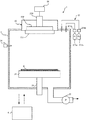
図1に示すように、成膜装置1は、密閉容器であるチャンバ2の底部付近に、ワークWが載置されるステージ21が設置されている。ワークWの種類は特定のものに限られないが、例えばポリカーボネート基板である。
As shown in FIG. 1, in the
ステージ21は円盤状であり、チャンバ2の底面から延びるシャフト22に連結され支持されている。シャフト22は、チャンバ2の底面を気密に貫通し、外部に連通している。チャンバ2には、排気装置25と圧力計26が設けられている。排気装置25は、例えばポンプであり、チャンバ2の内部を常時排気して、減圧状態に保つ。圧力計26はチャンバ2の圧力を計測する。
The
チャンバ2には、ワークWの搬入口20(図2参照)が設けられている。搬入口20は、不図示のロードロック室に接続され、ワークWは装置の外部から、ロードロック室を介してチャンバ2の内部に搬入される。ロードロック室にも排気装置が備えられており、ワークWの搬入する際に、ロードロック室を予め設定した圧力まで減圧してから搬入口20を開くことによって、チャンバ2の圧力の上昇を低減することができる。チャンバ2の圧力上昇の低減が目的であるため、予め設定するロードロック室の圧力は、大気圧よりは低いが、チャンバ2の圧力よりも高い圧力で良い。ロードロック室に備える排気装置は、チャンバ2の排気装置25よりも、排気性能が低いものであっても良い。
The
チャンバ2の上部には、スパッタ源23が配置されている。スパッタ源23は、ワークWに堆積されて膜となる成膜材料の供給源である。スパッタ源23は、ターゲット231、バッキングプレート232及び導電部材233から構成され、電源装置24に接続されている。
A sputtering
ターゲット231は、例えばチャンバ2の上面に取り付けられ、その表面がチャンバ2の底部付近に設置されたステージ21に対向するように配置されている。ターゲット231は成膜材料からなり、周知のあらゆる成膜材料を適用可能である。例えば、ITO膜を成膜する場合には、ターゲット231は酸化インジウムスズを含むものを使用する。ターゲット231の形状は、例えば、円柱形状である。但し、長円柱形状、角柱形状等、他の形状であってもよい。
The
バッキングプレート232は、ターゲット231のステージ21側とは反対側の面を保持する部材である。導電部材233は、バッキングプレート232と電源装置24を接続する部材である。なお、スパッタ源23には、必要に応じてマグネット、冷却機構などが設けられている。
The
電源装置24は、導電部材233及びバッキングプレート232を介して、ターゲット231に電圧を印加する構成部である。つまり、電源装置24は、ターゲット231に電圧を印加することにより、ターゲット231の周囲に導入されたスパッタガスをプラズマ化させ、成膜材料をワークWに堆積させる。本実施形態における電源装置24は、例えば、高電圧を印加するDC電源である。なお、高周波スパッタを行う装置の場合には、RF電源とすることもできる。
The
また、チャンバ2にはスパッタガス導入部27が設けられている。このスパッタガス導入部27から、チャンバ2の内部にスパッタガスを導入する。スパッタガスは特定のものに限定されないが、ITO膜の成膜には、例えば、アルゴン等の不活性ガスと酸素との混合ガスを用いることができる。混合ガスを用いる場合に、スパッタガス導入部は、チャンバ2に導入するスパッタガスにおけるアルゴンガスと酸素の導入分圧を制御する。具体的には、スパッタガス導入部27はアルゴンガス導入部271aと酸素導入部272aとから構成される。アルゴンガス導入部271aと酸素導入部272aにはそれぞれ流量制御計271b,272bが設置されている。流量制御計271b,272bは、アルゴンガスと酸素の流量を測定することにより、スパッタガスにおけるアルゴンガス分圧と酸素分圧をそれぞれ制御する。
The
制御装置4は、成膜装置1の各部の動作を制御する装置である。この制御装置4は、例えば、専用の電子回路若しくは所定のプログラムで動作するコンピュータ等によって構成できる。制御装置4には、各部の制御内容がプログラムされており、PLCやCPUなどの処理装置により実行される。このため、多種多様な成膜仕様に対応可能である。
The
このような制御装置4の構成を、仮想的な機能ブロック図である図2を参照して説明する。すなわち、制御装置4は、機構制御部41、酸素分圧決定部42、記憶部43、計時部44、警報生成部45、入出力制御部46を有する。
The configuration of the
機構制御部41は、成膜装置1の各部の機構を制御する処理部である。制御としては、例えば、ロードロック室の開閉及び内部圧力の制御、搬入口20の開閉、排気装置25の排気速度、スパッタガス導入部27のタイミング及び導入量の制御、電源装置24における電圧印加のタイミングと供給電力量の制御等が挙げられる。
The mechanism control unit 41 is a processing unit that controls the mechanism of each unit of the
酸素分圧決定部42は、チャンバ2の圧力を測定する圧力計26から圧力計26で測定されたベース圧力を取得する。酸素分圧決定部42は、記憶部43に記憶された最適酸素分圧のデータを参照して、取得したベース圧力に対応する最適酸素分圧を決定する。ベース圧力とは、スパッタガスを導入する前のチャンバ2の圧力であり、具体的には、チャンバ2にワークWを搬入して搬入口20を閉じてから、排気装置25によって予め設定された時間で排気を行った後の圧力である。この予め設定された時間を、以降は「排気時間t」という。最適酸素分圧とは、スパッタガスにおける酸素分圧の最適値である。
The oxygen partial
機構制御部41は、スパッタガスにおける酸素分圧が、酸素分圧決定部42で決定された最適酸素分圧となるように、制御信号を生成して酸素導入部272aの流量制御計272bに送信する。酸素導入部272aの流量制御計272bは、受信した制御信号に従って酸素の流量を調整して、スパッタガスにおける酸素分圧が最適酸素分圧となるように制御する。なお、本実施形態において、アルゴンガス分圧は固定とするため、アルゴンガスの流量制御計271bは予め決定されたアルゴンガス分圧に基づいて流量を調整する。
The mechanism control unit 41 generates a control signal and transmits it to the
記憶部43は、本実施形態の制御に必要な各種の情報を記憶するが、上述したように、本実施形態では最適酸素分圧のデータを記憶している。最適酸素分圧のデータは、予め試験等を行って得ることができるが、ベース圧力が上昇するにしたがって最適酸素分圧が減少する傾向となっている。ここで、ベース圧力の値が上昇するにしたがって、最適酸素分圧が減少する理由について説明する。
The
図3に、成膜処理におけるチャンバ2内部の圧力の変化を示している。成膜処理はワークWを入れ替えて繰り返し行われる。グラフでは、成膜を開始後のチャンバ2内部にITO膜が付着していない初期の状態の圧力の変化を実線で示し、成膜を繰り返してチャンバ2内部にITO膜が付着した後期の状態の圧力の変化を破線で示している。
FIG. 3 shows a change in pressure inside the
初期においても後期においても、圧力は全体的には同様の推移を示す。ワークWをチャンバ2の内部に搬入するときには、チャンバ2の圧力よりもロードロック室の圧力が高い状態で搬入口20を開放するため、圧力が上昇する(図中(1))。搬入口20を閉じた後、チャンバ2を所定の排気時間tだけ排気して、ベース圧力まで減圧する(図中(2))。その後、スパッタガスを導入することによって、圧力は上昇する(図中(3))。成膜処理中は、スパッタガスの量が一定に保たれるように、排気とスパッタガスの供給が行われる。(図中(4))。成膜完了後は、スパッタガスの導入を止めるため、圧力が減少する。
In the early and late stages, the pressure generally shows the same transition. When the work W is carried into the
しかしながら、ワークW搬入後に同じ排気時間tで排気した場合でも、後期の方が初期よりもベース圧力が高くなっている。これは、成膜によってチャンバ2の内壁に付着したITO膜に、ワークWの搬入時に入り込んだ外部の空気や空気中の水蒸気等のガスが吸着するためと考えられる。吸着したガスは、チャンバ2をベース圧力に減圧するときにアウトガスとしてチャンバ2の内部に放出される。成膜を繰り返すと付着するITO膜の量も増えるため、アウトガスの量も増えていく。そのため、同じ排気時間tで排気した場合、放出されるアウトガスの分だけ、ベース圧力が高くなる。
However, even if the exhaust is performed at the same exhaust time t after the work W is carried in, the base pressure is higher in the latter period than in the initial period. This is presumably because gas such as external air that has entered the work W when it is carried in or water vapor in the air is adsorbed to the ITO film attached to the inner wall of the
アウトガスには酸素が含まれるため、スパッタガスにおける酸素分圧を一定にしたままであれば、スパッタガスの酸素とアウトガスに含まれる酸素との和が次第に大きくなっていく。結果として成膜処理の際にプラズマ化される酸素の量が多くなる。 Since the outgas contains oxygen, if the oxygen partial pressure in the sputtering gas remains constant, the sum of the oxygen in the sputtering gas and the oxygen contained in the outgas gradually increases. As a result, the amount of oxygen that is converted into plasma during the film forming process increases.
成膜処理における酸素が適正量を超えると、製品における抵抗値も増加する。図4は、スパッタガスにおける酸素分圧を一定にしたままで成膜装置1を稼働し続けた場合の、ITO膜の抵抗値の変化を模式的に示したグラフである。図4に示すように、酸素分圧を一定にしたまま装置を稼働し続けると、ITO膜の抵抗値は比例的に増加する。抵抗値が一定以上になると、製品として不良品と判定される可能性がある。
When the oxygen in the film forming process exceeds an appropriate amount, the resistance value in the product also increases. FIG. 4 is a graph schematically showing a change in the resistance value of the ITO film when the
しかしながら、アウトガスにおける酸素の増加量に応じて、スパッタガスの酸素分圧を減少させれば、成膜処理における酸素を適正量に保ち、抵抗値の増加を抑えることができる。アウトガスにおける酸素の増加量は測定することが困難であるが、上述したように、アウトガスの量の増加に応じてベース圧力が上昇する。すなわち、圧力計26で測定することができるベース圧力の上昇に応じてスパッタガスにおける酸素分圧を減少させることによって、成膜処理の際の酸素量を適正量に保つことができる。そのような観点から、予め試験等を行い、ベース圧力に応じた最適酸素分圧のデータを作成して、記憶部43に保存する。
However, if the oxygen partial pressure of the sputtering gas is reduced in accordance with the amount of oxygen increase in the outgas, it is possible to maintain an appropriate amount of oxygen in the film formation process and suppress an increase in resistance value. Although it is difficult to measure the increase amount of oxygen in the outgas, as described above, the base pressure increases as the amount of outgas increases. That is, by reducing the oxygen partial pressure in the sputtering gas in accordance with the increase in the base pressure that can be measured by the
記憶部43にはまた、ベース圧力の上限値も記憶しておくと良い。ベース圧力が上昇し続ける、すなわち、アウトガスの量が増加し続けると、アウトガスに含まれる酸素のみで成膜処理に必要な酸素の量を超える可能性がある。さらに、チャンバ2の圧力が高くなりすぎると、ITO膜の密度や均質性に影響を与える。結果として、スパッタガスの酸素分圧を減らしたとしても、ITO膜の抵抗値の上昇を防げなくなってしまう。そのような場合はチャンバ2内の清掃を行ってチャンバ2の内壁に付着したITO膜を除去する必要がある。上限値は、予め試験等を行って決定すると良いが、例えば6×10⁻³[Pa]としても良い。
The
計時部44は、時間をカウントするタイマーである。機構制御部41は、計時部44でカウントされる時間に基づいて、ワークWの搬入及び搬出のタイミング、スパッタガスの導入及び停止のタイミング、電圧印加のタイミング等を制御する。また、酸素分圧決定部42は、ワークWを搬入し搬入口20を閉じてから、計時部44によってカウントされる時間が所定の排気時間tを経過したところで、圧力計26からベース圧力の測定値を取得する。
The
警報生成部45は、圧力計26から取得されるベース圧力が、記憶部43に記憶された上限値を超えたとき、警報を生成する。警報は、例えば、ベース圧力の値とチャンバ2内の清掃が必要となった旨を報知するものとしても良い。
The
入出力制御部46は、制御対象となる各部との間での信号の変換や入出力を制御するインタフェースである。
The input /
さらに、制御装置4には、入力装置47、出力装置48が接続されている。入力装置47は、オペレータが、制御装置4を介して成膜装置1を操作するためのスイッチ、タッチパネル、キーボード、マウス等の入力手段である。上述した最適酸素分圧のデータは、入力装置47から所望の値を入力することができる。
Furthermore, an
出力装置48は、装置の状態を確認するための情報を、オペレータが視認可能な状態とするディスプレイ、ランプ、メータ等の出力手段である。出力装置48は、例えば、警報生成部45で生成された警報を出力する。
The
[動作]
次に、本実施形態に係る成膜装置1の動作及び成膜方法について説明する。以下に述べる成膜装置1の動作は、制御装置4の機構制御部41によって制御されるものである。ワークWは、大気圧の外部からロードロック室に搬入される。ロードロック室を予め設定された圧力まで減圧してから搬入口20を開き、チャンバ2の内部にワークWを搬入する。ロードロック室の圧力はチャンバ2の圧力よりも高いため、搬入口20を開いたときにチャンバ2の圧力は一時的に上昇する。搬入したワークWはステージ21に載置する。ワークWの搬入は、不図示の搬送装置で行う。ステージ21に載置した後は、搬入口20を閉じてチャンバ2を密閉する。チャンバ2は排気装置25によって常時排気されているため、搬入口20を閉じることによってチャンバ2は減圧される。
[Operation]
Next, the operation and film forming method of the
制御装置4の酸素分圧決定部42は、搬入口20を閉じてから、計時部44によってカウントされる時間が所定の排気時間tを経過した時点で、圧力計26からベース圧力の値を取得する。
The oxygen partial
酸素分圧決定部42は、記憶部43の最適酸素分圧のデータを参照し、圧力計26から取得したベース圧力に対応する最適酸素分圧の値を決定する。機構制御部41は、酸素分圧決定部42で決定された最適酸素分圧に基づいて制御信号を生成し、酸素導入部272aの流量制御計272bに送信する。流量制御計272bは、スパッタガスにおける酸素分圧が最適酸素分圧となるように流量を調整する。
The oxygen partial
スパッタガス導入部27からスパッタガスをチャンバ2の内部に導入して、電源装置24からターゲット231に直流電圧を印加する。直流電圧の印加によってスパッタガスがプラズマ化し、イオンが発生する。発生したイオンがターゲット231に衝突すると、ターゲット231の成膜材料の粒子が飛び出す。飛び出した粒子がステージ21に載置されたワークWに堆積することで、ワークW上に薄膜が形成される。
A sputtering gas is introduced into the
成膜処理が完了すると、スパッタガスの導入を停止し、搬入口20を開放して成膜したワークWをチャンバ2内部から搬出し、次のワークWを搬入する。後続するワークWについても、最初のワークWと同様の工程で、順次成膜処理を行っていく。ただし、成膜処理を繰り返すとITO膜がチャンバ2内部に付着してアウトガスが発生するため、圧力計26で測定されるベース圧力の値は徐々に上昇する。酸素分圧決定部42は記憶部43の最適酸素分圧のデータを参照して、上昇したベース圧力に対応する最適酸素分圧を決定する。したがって、スパッタガスにおける酸素分圧は徐々に減少していくため、成膜処理における酸素の量が適正な範囲に保たる。これによって、成膜処理を繰り返しても、ベース圧力が上限値を超えるまで、膜の品質を保った成膜が行われる。
When the film forming process is completed, the introduction of the sputtering gas is stopped, the
圧力計26で測定されるベース圧力の値が、上限値を超えた場合、警報生成部45は警報を生成して、出力装置48に出力する。警報を出力した時点で、成膜処理を中断させても良く、あるいは警報を出力した上で成膜処理を継続させても良い。
When the value of the base pressure measured by the
[実施例]
上述の実施形態の成膜装置1において、以下の条件で成膜処理を行った。
・DC電力[kW]: 3.5
・Arガス圧力[Pa]: 1.46(420sccm)
・O2圧力[Pa]: 0.037(12.5sccm)
・成膜圧力(Ar+O2)[Pa]: 1.50
・放電電圧[V]: 398
・排気時間[s]:23.4
・成膜時間[s]: 5.2
・成膜速度[nm/s]: 7.7
・ターゲット231:酸化インジウムスズ(ITO)
・膜厚[nm]:40
・ワークW:ポリカーボネート基板
[Example]
In the
・ DC power [kW]: 3.5
Ar gas pressure [Pa]: 1.46 (420 sccm)
・ O 2 pressure [Pa]: 0.037 (12.5sccm)
Film forming pressure (Ar + O 2 ) [Pa]: 1.50
・ Discharge voltage [V]: 398
・ Exhaust time [s]: 23.4
・ Deposition time [s]: 5.2
・ Deposition rate [nm / s]: 7.7
Target 231: Indium tin oxide (ITO)
Film thickness [nm]: 40
・ Work W: Polycarbonate substrate
上記条件で複数枚のワークWに対して連続して成膜処理を行った。各成膜処理において、ワークWをチャンバ2内に搬入してから排気時間が経過した時点で、ベース圧力を測定した。初期のベース圧力は、2×10⁻³[Pa]であったが、成膜処理を繰り返すとベース圧力が上昇した。図5のグラフに示すように、ベース圧力の上昇に応じて酸素分圧を減少させた。
Film formation processing was continuously performed on a plurality of workpieces W under the above conditions. In each film forming process, the base pressure was measured when the exhaust time elapsed after the work W was carried into the
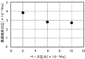
2×10⁻³[Pa]、6×10⁻³[Pa]、10×10−3[Pa]のベース圧力でそれぞれ成膜を行ったワークWに対して、80℃で92時間の加熱試験を行い、加熱後の抵抗値を測定した。加熱試験の結果を、図6のグラフに示している。ベース圧力6×10⁻³[Pa]で成膜を行ったITO膜は、初期のベース圧力2×10⁻³[Pa]に対する抵抗増加率が低い。すなわち、スパッタガスの酸素分圧を減少させたことで、成膜処理における酸素が適正量に保たれていることがわかる。一方、ベース圧力10×10−3[Pa]では、酸素分圧を減少させているが、初期のベース圧力2×10⁻³[Pa]に対する抵抗増加率が大きい。これは、アウトガスに含まれる酸素が、スパッタガスの酸素分圧の減少によって調整可能な量を超えたか、チャンバ2の圧力が高くなり、膜の密度や均質性に影響を与えたためと考えられる。
A heating test for 92 hours at 80 ° C. on the workpiece W on which the film was formed at a base pressure of 2 × 10 −3 [Pa], 6 × 10 −3 [Pa], and 10 × 10 −3 [Pa] The resistance value after heating was measured. The result of the heating test is shown in the graph of FIG. An ITO film formed at a base pressure of 6 × 10 −3 [Pa] has a low resistance increase rate with respect to an initial base pressure of 2 × 10 −3 [Pa]. That is, it can be seen that the oxygen in the film forming process is maintained at an appropriate amount by reducing the oxygen partial pressure of the sputtering gas. On the other hand, at the base pressure of 10 × 10 −3 [Pa], the oxygen partial pressure is decreased, but the resistance increase rate with respect to the initial base pressure of 2 × 10 −3 [Pa] is large. This is presumably because the oxygen contained in the outgas exceeded the amount that can be adjusted by reducing the oxygen partial pressure of the sputtering gas, or the pressure in the
[効果]
(1)本実施形態の成膜装置1は、成膜材料からなるターゲット231が配置され、内部にワークWが搬入される密閉容器であるチャンバ2と、ワークWの搬入後、チャンバ2を所定の排気時間、排気してベース圧力にする排気装置25と、ベース圧力に排気されたチャンバ2の内部に、酸素を含むスパッタガスを導入するスパッタガス導入部27と、を備える。スパッタガス導入部27は、チャンバ2の内部に付着する成膜材料の増加によるベース圧力の上昇に応じて、チャンバ2に導入するスパッタガスの酸素分圧を減少させる。
[effect]
(1) The
アウトガスの発生によって上昇するベース圧力を基準として、スパッタガス中の酸素の導入分圧を調整することで、チャンバ2内における酸素を適正量に保って成膜を行うことができる。これによって、良好な品質で、かつ品質のバラつきが少ない成膜を行うことができる、信頼性の高い成膜装置1及び成膜方法を提供することができる。
By adjusting the partial pressure of oxygen introduced into the sputtering gas with reference to the base pressure that rises as a result of outgas generation, film formation can be performed while maintaining an appropriate amount of oxygen in the
成膜装置1は、ベース圧力を計測する圧力計26と、圧力計26で測定されたベース圧力に応じて、スパッタガス導入部27が導入するスパッタガスの酸素分圧を決定する制御装置4と、を備える。圧力計26はチャンバ2の圧力管理のために通常設置されるものであり、ベース圧力は圧力計26から容易に取得できる。よって、高精度な計器等を必要とせずに酸素分圧を制御することができ、経済性が高い。
The
[第2の実施形態]
本発明の第2の実施形態について、図面を参照して説明する。なお、第1の実施形態の構成要素と同一の構成要素については、同一の符号を付与し詳細な説明を省略する。
[Second Embodiment]
A second embodiment of the present invention will be described with reference to the drawings. In addition, about the component same as the component of 1st Embodiment, the same code | symbol is provided and detailed description is abbreviate | omitted.
第2の実施形態の成膜装置1の全体的な構成は、第1の実施形態と同様である。第2の実施形態の成膜装置1の制御装置4の機能構成を、図7に示している。制御装置4は、第1の実施形態と同様の構成に加え、ベース圧力決定部49を備えている。第1の実施形態では、機構制御部41が圧力計26で測定されたベース圧力の値を取得していたが、第2の実施形態では、電源装置24からターゲット231に供給された積算電力量に基づいてベース圧力を決定する。
The overall configuration of the
積算電力量とは、ワークWを入れ替えて成膜処理を連続して行う場合に、各成膜処理において電源装置24からターゲット231に供給された電力の積算量である。図8に示すように、積算電力量は、成膜処理を繰り返すごとに増加していく。第1の実施形態でも述べたように、ベース圧力も、成膜処理を繰り返すごとに増加していく。すなわち、積算電力量の増加に応じて、ベース圧力も増加していく。そこで、予め試験等を行って、積算電力量に対応するベース圧力のデータを作成し、記憶部43に記憶させる。
The integrated power amount is an integrated amount of power supplied from the
上述したように、機構制御部41は、電源装置24における電圧印加のタイミングと供給電力量を制御する。ベース圧力決定部49は、機構制御部41から供給電力量を取得して積算電力量を算出する。そして、記憶部43に記憶させたベース圧力のデータを参照し、算出した積算電力量に対応するベース圧力を決定する。
As described above, the mechanism control unit 41 controls the voltage application timing and the power supply amount in the
酸素分圧決定部42は、記憶部43に記憶された最適酸素分圧のデータを参照して、ベース圧力決定部49で決定されたベース圧力に対応する最適酸素分圧を決定する。機構制御部41は、スパッタガスにおける酸素分圧が、酸素分圧決定部42で決定された最適酸素分圧となるように、制御信号を生成して酸素導入部272aの流量制御計272bに送信する。酸素導入部272aの流量制御計272bは、受信した制御信号に従ってチャンバ2に導入する酸素の流量を調整する。
The oxygen partial
以上述べたように、第2の実施形態では、制御装置4は、電源装置24からターゲット231に供給された積算電力量に基づいて決定したベース圧力に応じて、スパッタガス導入部27におけるスパッタガスの酸素分圧を決定する。チャンバ2内部の環境や成膜状況等の事情によって、ベース圧力が測定できない場合であっても、積算電力量からベース圧力を決定することができ、第1の実施形態と同様にスパッタガスの酸素分圧を調整し、酸素を適正量に保って成膜を行うことができる
As described above, in the second embodiment, the
[その他の実施形態]
本発明は、上記の実施形態に限定されるものではない。例えば、上述した成膜装置1は、スパッタリング等の成膜処理とエッチング等の膜処理を行う複数のチャンバを備えた、マルチチャンバ型のプラズマ処理装置に適用しても良い。
[Other Embodiments]
The present invention is not limited to the above embodiment. For example, the
また、上述の実施形態では、搬入口20にロードロック室が接続されている例を説明したが、これに限定されず、外部から搬入口20に直接ワークWを搬入しても良い。ロードロック室を使用しないと、ワークWの搬入時に入り込む外部の空気が増え、結果としてチャンバ2の内壁に付着したITO膜からのアウトガスの量は増加する可能性があるため、例えば、排気時間tを長くして、入り込んだ外部の空気が排気されるようにすると良い。また、ロードロック室を使用しない場合は、搬入口20を開くとチャンバ2の内部が大気圧まで上昇するため、搬入口20を開いている間は排気装置25を停止させ、搬入口を閉じた後に排気装置25を稼働して排気を開始しても良い。
In the above-described embodiment, an example in which the load lock chamber is connected to the carry-in
以上、本発明の実施形態及び各部の変形例を説明したが、この実施形態や各部の変形例は、一例として提示したものであり、発明の範囲を限定することは意図していない。上述したこれら新規な実施形態は、その他の様々な形態で実施されることが可能であり、発明の要旨を逸脱しない範囲で、種々の省略、置き換え、変更を行うことができる。これら実施形態やその変形は、発明の範囲や要旨に含まれるとともに、特許請求の範囲に記載された発明に含まれる。 As mentioned above, although embodiment of this invention and the modification of each part were demonstrated, this embodiment and the modification of each part are shown as an example, and are not intending limiting the range of invention. These novel embodiments described above can be implemented in various other forms, and various omissions, replacements, and changes can be made without departing from the spirit of the invention. These embodiments and modifications thereof are included in the scope and gist of the invention and included in the invention described in the claims.
1 成膜装置
2 チャンバ
20 搬入口
21 ステージ
22 シャフト
23 スパッタ源
231 ターゲット
232 バッキングプレート
233 導電部材
24 電源装置
25 排気装置
26 圧力計
27 スパッタガス導入部
271a アルゴンガス導入部
272a 酸素導入部
271b,272b 流量制御計
4 制御装置
41 機構制御部
42 酸素分圧決定部
43 記憶部
44 計時部
45 警報生成部
46 入出力制御部
47 入力装置
48 出力装置
49 ベース圧力決定部
W ワーク
DESCRIPTION OF
Claims (5)
成膜材料からなるターゲットが配置され、内部に前記ワークが搬入される密閉容器と、
前記ワークの搬入後、前記密閉容器を所定時間排気してベース圧力にする排気装置と、
前記ベース圧力に排気された前記密閉容器の内部に、酸素を含むスパッタガスを導入するスパッタガス導入部と、を備え、
前記スパッタガス導入部は、前記密閉容器内部に付着する前記成膜材料の増加による前記ベース圧力の上昇に応じて、前記密閉容器に導入する前記スパッタガスの酸素分圧を減少させることを特徴とする成膜装置。 A film forming apparatus for forming a film on a workpiece using plasma,
A sealed container in which a target made of a film forming material is arranged, and the workpiece is carried inside;
An exhaust device for exhausting the sealed container for a predetermined time to bring the base pressure to the base pressure after the work is loaded;
A sputtering gas introduction part for introducing a sputtering gas containing oxygen into the sealed container evacuated to the base pressure;
The sputtering gas introduction unit reduces the oxygen partial pressure of the sputtering gas introduced into the sealed container in accordance with an increase in the base pressure due to an increase in the film forming material adhering to the inside of the sealed container. A film forming apparatus.
前記圧力計で測定された前記ベース圧力に応じて、前記スパッタガス導入部が導入する前記スパッタガスの酸素分圧を決定する制御装置と、を備えることを特徴とする請求項1記載の成膜装置。 A pressure gauge for measuring the base pressure;
The film forming apparatus according to claim 1, further comprising: a control device that determines an oxygen partial pressure of the sputtering gas introduced by the sputtering gas introduction unit in accordance with the base pressure measured by the pressure gauge. apparatus.
前記電源装置から前記ターゲットに供給された電力の積算量に基づいて決定した前記ベース圧力に応じて、前記スパッタガス導入部が導入する前記スパッタガスの酸素分圧を決定する制御装置と、を備えることを特徴とする請求項1記載の成膜装置。 A power supply device for applying a voltage to the target;
A control device that determines an oxygen partial pressure of the sputtering gas introduced by the sputtering gas introduction unit according to the base pressure determined based on an integrated amount of power supplied from the power supply device to the target. The film forming apparatus according to claim 1.
成膜材料からなるターゲットが配置された密閉容器の内部に前記ワークを搬入し、
前記ワークの搬入後、前記密閉容器を所定時間排気してベース圧力にし、
前記ベース圧力に排気された前記密閉容器の内部に、酸素を含むスパッタガスを導入し、
前記密閉容器内部に付着する前記成膜材料の増加による前記ベース圧力の上昇に応じて、前記密閉容器に導入する前記スパッタガスの酸素分圧を減少させることを特徴とする成膜方法。 A film forming method for forming a film on a workpiece using plasma,
The work is carried into a sealed container in which a target made of a film forming material is placed,
After carrying in the workpiece, the sealed container is evacuated for a predetermined time to a base pressure,
Introducing a sputtering gas containing oxygen into the sealed container evacuated to the base pressure,
A film forming method comprising: reducing an oxygen partial pressure of the sputtering gas introduced into the sealed container in accordance with an increase in the base pressure due to an increase in the film forming material adhering to the inside of the sealed container.
Priority Applications (5)
| Application Number | Priority Date | Filing Date | Title |
|---|---|---|---|
| JP2016053446A JP6775972B2 (en) | 2016-03-17 | 2016-03-17 | Film formation equipment and film formation method |
| KR1020170023939A KR101976254B1 (en) | 2016-03-17 | 2017-02-23 | Film forming apparatus and film forming method |
| CN201710148173.1A CN107201503B (en) | 2016-03-17 | 2017-03-13 | Film forming apparatus and film forming method |
| TW106108632A TWI641711B (en) | 2016-03-17 | 2017-03-16 | Film forming device and film forming method |
| US15/461,906 US10260145B2 (en) | 2016-03-17 | 2017-03-17 | Film formation apparatus and film formation method |
Applications Claiming Priority (1)
| Application Number | Priority Date | Filing Date | Title |
|---|---|---|---|
| JP2016053446A JP6775972B2 (en) | 2016-03-17 | 2016-03-17 | Film formation equipment and film formation method |
Related Child Applications (1)
| Application Number | Title | Priority Date | Filing Date |
|---|---|---|---|
| JP2020170135A Division JP7100098B2 (en) | 2020-10-07 | 2020-10-07 | Film forming equipment and film forming method |
Publications (2)
| Publication Number | Publication Date |
|---|---|
| JP2017166032A true JP2017166032A (en) | 2017-09-21 |
| JP6775972B2 JP6775972B2 (en) | 2020-10-28 |
Family
ID=59848328
Family Applications (1)
| Application Number | Title | Priority Date | Filing Date |
|---|---|---|---|
| JP2016053446A Active JP6775972B2 (en) | 2016-03-17 | 2016-03-17 | Film formation equipment and film formation method |
Country Status (5)
| Country | Link |
|---|---|
| US (1) | US10260145B2 (en) |
| JP (1) | JP6775972B2 (en) |
| KR (1) | KR101976254B1 (en) |
| CN (1) | CN107201503B (en) |
| TW (1) | TWI641711B (en) |
Families Citing this family (5)
| Publication number | Priority date | Publication date | Assignee | Title |
|---|---|---|---|---|
| KR102077224B1 (en) | 2018-08-14 | 2020-02-13 | 농업회사법인 한국도시농업 주식회사 | Chain conveyor type unmanned automatic crop cultivating machine for increase of production volume |
| KR102219858B1 (en) | 2018-08-27 | 2021-02-24 | 농업회사법인 한국도시농업 주식회사 | Autonomous rotating irrigation system of cultivating equipment of cone type crop |
| KR20200061256A (en) | 2018-11-23 | 2020-06-02 | 김근우 | Irrigation circulation system of cultivating equipment of cone type crop |
| KR102143699B1 (en) | 2018-11-23 | 2020-08-12 | (주)케이피 | Irrigation system of cultivating equipment of cone type crop |
| CN114277349A (en) * | 2021-12-28 | 2022-04-05 | 无锡展硕科技有限公司 | Novel physical vapor deposition equipment capable of adjusting chamber temperature |
Family Cites Families (10)
| Publication number | Priority date | Publication date | Assignee | Title |
|---|---|---|---|---|
| US4331856A (en) * | 1978-10-06 | 1982-05-25 | Wellman Thermal Systems Corporation | Control system and method of controlling ion nitriding apparatus |
| JPS56133459A (en) * | 1980-03-21 | 1981-10-19 | Agency Of Ind Science & Technol | Vapor-depositing apparatus |
| JPS5894703A (en) | 1981-11-30 | 1983-06-06 | 松下電器産業株式会社 | Method of producing transparent electrode and device for producing same |
| KR100207279B1 (en) * | 1996-01-31 | 1999-07-15 | 김희용 | Method of coloring the metal product |
| DE102004014855A1 (en) * | 2004-03-26 | 2004-10-21 | Applied Films Gmbh & Co. Kg | Device for reactive sputtering comprises a controllable valve to control the total gas flow into a sputtering chamber, and a control unit for keeping the ratio of the partial pressures of at least two gases constant |
| JP5570951B2 (en) * | 2009-12-26 | 2014-08-13 | キヤノンアネルバ株式会社 | Reactive sputtering method and reactive sputtering apparatus |
| JP5598407B2 (en) | 2011-04-05 | 2014-10-01 | 株式会社島津製作所 | Film forming apparatus and film forming method |
| EP2770083B1 (en) * | 2013-02-20 | 2015-11-18 | University of West Bohemia in Pilsen | High-rate reactive sputtering of dielectric stoichiometric films |
| JP6101533B2 (en) * | 2013-03-27 | 2017-03-22 | 株式会社Screenホールディングス | Aluminum oxide film formation method |
| JP2015021173A (en) * | 2013-07-19 | 2015-02-02 | 日東電工株式会社 | Film deposition apparatus |
-
2016
- 2016-03-17 JP JP2016053446A patent/JP6775972B2/en active Active
-
2017
- 2017-02-23 KR KR1020170023939A patent/KR101976254B1/en active IP Right Grant
- 2017-03-13 CN CN201710148173.1A patent/CN107201503B/en active Active
- 2017-03-16 TW TW106108632A patent/TWI641711B/en active
- 2017-03-17 US US15/461,906 patent/US10260145B2/en active Active
Also Published As
| Publication number | Publication date |
|---|---|
| US20170268098A1 (en) | 2017-09-21 |
| TW201734242A (en) | 2017-10-01 |
| KR20170108819A (en) | 2017-09-27 |
| CN107201503B (en) | 2020-06-23 |
| US10260145B2 (en) | 2019-04-16 |
| CN107201503A (en) | 2017-09-26 |
| KR101976254B1 (en) | 2019-05-07 |
| JP6775972B2 (en) | 2020-10-28 |
| TWI641711B (en) | 2018-11-21 |
Similar Documents
| Publication | Publication Date | Title |
|---|---|---|
| CN107201503B (en) | Film forming apparatus and film forming method | |
| JP6667343B2 (en) | Plasma processing apparatus and plasma processing method | |
| JP2008526026A5 (en) | ||
| TW201714244A (en) | Substrate transport device and substrate transport method | |
| KR20140027202A (en) | Improved method of controlling lithium uniformity | |
| JP5661452B2 (en) | Sputtering method | |
| JPH0772307A (en) | Method and device for forming thin film | |
| JP6202098B2 (en) | Film forming apparatus and film forming method | |
| JP7100098B2 (en) | Film forming equipment and film forming method | |
| JP2006328510A (en) | Plasma treatment method and device | |
| JP2015101768A (en) | Film deposition apparatus | |
| JP5433786B2 (en) | Sputtering equipment production return method | |
| JP2019094534A (en) | Sputtering device and method of manufacturing film | |
| JP2011168825A (en) | Substrate treatment device and method for manufacturing semiconductor device | |
| JP6608537B2 (en) | Film forming apparatus and film forming method | |
| JP2014114497A (en) | Sputtering equipment | |
| JP2015113513A (en) | Film deposition apparatus and film deposition method | |
| JPH11304629A (en) | Leak detecting method for vacuum container, monitoring apparatus for film formation quality and continuous vacuum film formation apparatus | |
| JP2015151618A (en) | Film deposition apparatus | |
| JP2007031815A (en) | Planer magnetron sputtering apparatus and planer magnetron sputtering film deposition method | |
| JP2024056319A (en) | Film forming apparatus and film forming method | |
| JP5533569B2 (en) | Plasma processing apparatus and processing method | |
| WO2006129671A1 (en) | Film forming apparatus and method | |
| JP2003034857A (en) | Sputtering apparatus and method | |
| JP6513514B2 (en) | Temperature measurement method |
Legal Events
| Date | Code | Title | Description |
|---|---|---|---|
| A621 | Written request for application examination |
Free format text: JAPANESE INTERMEDIATE CODE: A621 Effective date: 20190131 |
|
| A977 | Report on retrieval |
Free format text: JAPANESE INTERMEDIATE CODE: A971007 Effective date: 20191122 |
|
| A131 | Notification of reasons for refusal |
Free format text: JAPANESE INTERMEDIATE CODE: A131 Effective date: 20191203 |
|
| A521 | Request for written amendment filed |
Free format text: JAPANESE INTERMEDIATE CODE: A523 Effective date: 20200128 |
|
| A131 | Notification of reasons for refusal |
Free format text: JAPANESE INTERMEDIATE CODE: A131 Effective date: 20200630 |
|
| A521 | Request for written amendment filed |
Free format text: JAPANESE INTERMEDIATE CODE: A523 Effective date: 20200827 |
|
| TRDD | Decision of grant or rejection written | ||
| A01 | Written decision to grant a patent or to grant a registration (utility model) |
Free format text: JAPANESE INTERMEDIATE CODE: A01 Effective date: 20200908 |
|
| A61 | First payment of annual fees (during grant procedure) |
Free format text: JAPANESE INTERMEDIATE CODE: A61 Effective date: 20201007 |
|
| R150 | Certificate of patent or registration of utility model |
Ref document number: 6775972 Country of ref document: JP Free format text: JAPANESE INTERMEDIATE CODE: R150 |