JP2017165135A - Method for production of pneumatic tire - Google Patents
Method for production of pneumatic tire Download PDFInfo
- Publication number
- JP2017165135A JP2017165135A JP2016049740A JP2016049740A JP2017165135A JP 2017165135 A JP2017165135 A JP 2017165135A JP 2016049740 A JP2016049740 A JP 2016049740A JP 2016049740 A JP2016049740 A JP 2016049740A JP 2017165135 A JP2017165135 A JP 2017165135A
- Authority
- JP
- Japan
- Prior art keywords
- layer
- tie rubber
- rubber layer
- tire
- partial tie
- Prior art date
- Legal status (The legal status is an assumption and is not a legal conclusion. Google has not performed a legal analysis and makes no representation as to the accuracy of the status listed.)
- Granted
Links
Images


Classifications
-
- B—PERFORMING OPERATIONS; TRANSPORTING
- B29—WORKING OF PLASTICS; WORKING OF SUBSTANCES IN A PLASTIC STATE IN GENERAL
- B29D—PRODUCING PARTICULAR ARTICLES FROM PLASTICS OR FROM SUBSTANCES IN A PLASTIC STATE
- B29D30/00—Producing pneumatic or solid tyres or parts thereof
- B29D30/06—Pneumatic tyres or parts thereof (e.g. produced by casting, moulding, compression moulding, injection moulding, centrifugal casting)
- B29D30/08—Building tyres
- B29D30/34—Building tyres by jointly covering two bead-rings, located parallel to each other at a distance apart, with fabric or cord layers
-
- B—PERFORMING OPERATIONS; TRANSPORTING
- B29—WORKING OF PLASTICS; WORKING OF SUBSTANCES IN A PLASTIC STATE IN GENERAL
- B29D—PRODUCING PARTICULAR ARTICLES FROM PLASTICS OR FROM SUBSTANCES IN A PLASTIC STATE
- B29D30/00—Producing pneumatic or solid tyres or parts thereof
- B29D30/06—Pneumatic tyres or parts thereof (e.g. produced by casting, moulding, compression moulding, injection moulding, centrifugal casting)
- B29D30/08—Building tyres
-
- B—PERFORMING OPERATIONS; TRANSPORTING
- B60—VEHICLES IN GENERAL
- B60C—VEHICLE TYRES; TYRE INFLATION; TYRE CHANGING; CONNECTING VALVES TO INFLATABLE ELASTIC BODIES IN GENERAL; DEVICES OR ARRANGEMENTS RELATED TO TYRES
- B60C5/00—Inflatable pneumatic tyres or inner tubes
- B60C5/12—Inflatable pneumatic tyres or inner tubes without separate inflatable inserts, e.g. tubeless tyres with transverse section open to the rim
- B60C5/14—Inflatable pneumatic tyres or inner tubes without separate inflatable inserts, e.g. tubeless tyres with transverse section open to the rim with impervious liner or coating on the inner wall of the tyre
- B60C5/142—Inflatable pneumatic tyres or inner tubes without separate inflatable inserts, e.g. tubeless tyres with transverse section open to the rim with impervious liner or coating on the inner wall of the tyre provided partially, i.e. not covering the whole inner wall
-
- B—PERFORMING OPERATIONS; TRANSPORTING
- B60—VEHICLES IN GENERAL
- B60C—VEHICLE TYRES; TYRE INFLATION; TYRE CHANGING; CONNECTING VALVES TO INFLATABLE ELASTIC BODIES IN GENERAL; DEVICES OR ARRANGEMENTS RELATED TO TYRES
- B60C9/00—Reinforcements or ply arrangement of pneumatic tyres
- B60C9/02—Carcasses
- B60C9/04—Carcasses the reinforcing cords of each carcass ply arranged in a substantially parallel relationship
- B60C9/08—Carcasses the reinforcing cords of each carcass ply arranged in a substantially parallel relationship the cords extend transversely from bead to bead, i.e. radial ply
-
- B—PERFORMING OPERATIONS; TRANSPORTING
- B60—VEHICLES IN GENERAL
- B60C—VEHICLE TYRES; TYRE INFLATION; TYRE CHANGING; CONNECTING VALVES TO INFLATABLE ELASTIC BODIES IN GENERAL; DEVICES OR ARRANGEMENTS RELATED TO TYRES
- B60C9/00—Reinforcements or ply arrangement of pneumatic tyres
- B60C9/02—Carcasses
- B60C9/14—Carcasses built-up with sheets, webs, or films of homogeneous material, e.g. synthetics, sheet metal, rubber
-
- B—PERFORMING OPERATIONS; TRANSPORTING
- B60—VEHICLES IN GENERAL
- B60C—VEHICLE TYRES; TYRE INFLATION; TYRE CHANGING; CONNECTING VALVES TO INFLATABLE ELASTIC BODIES IN GENERAL; DEVICES OR ARRANGEMENTS RELATED TO TYRES
- B60C9/00—Reinforcements or ply arrangement of pneumatic tyres
- B60C9/18—Structure or arrangement of belts or breakers, crown-reinforcing or cushioning layers
-
- B—PERFORMING OPERATIONS; TRANSPORTING
- B29—WORKING OF PLASTICS; WORKING OF SUBSTANCES IN A PLASTIC STATE IN GENERAL
- B29D—PRODUCING PARTICULAR ARTICLES FROM PLASTICS OR FROM SUBSTANCES IN A PLASTIC STATE
- B29D30/00—Producing pneumatic or solid tyres or parts thereof
- B29D30/06—Pneumatic tyres or parts thereof (e.g. produced by casting, moulding, compression moulding, injection moulding, centrifugal casting)
- B29D30/08—Building tyres
- B29D30/10—Building tyres on round cores, i.e. the shape of the core is approximately identical with the shape of the completed tyre
- B29D30/16—Applying the layers; Guiding or stretching the layers during application
- B29D2030/1664—Details, accessories or auxiliary operations not provided for in the other subgroups of B29D30/00
- B29D2030/1678—Details, accessories or auxiliary operations not provided for in the other subgroups of B29D30/00 the layers being applied being substantially continuous, i.e. not being cut before the application step
-
- B—PERFORMING OPERATIONS; TRANSPORTING
- B29—WORKING OF PLASTICS; WORKING OF SUBSTANCES IN A PLASTIC STATE IN GENERAL
- B29D—PRODUCING PARTICULAR ARTICLES FROM PLASTICS OR FROM SUBSTANCES IN A PLASTIC STATE
- B29D30/00—Producing pneumatic or solid tyres or parts thereof
- B29D30/06—Pneumatic tyres or parts thereof (e.g. produced by casting, moulding, compression moulding, injection moulding, centrifugal casting)
- B29D30/48—Bead-rings or bead-cores; Treatment thereof prior to building the tyre
- B29D2030/487—Forming devices for manufacturing the beads
-
- B—PERFORMING OPERATIONS; TRANSPORTING
- B60—VEHICLES IN GENERAL
- B60C—VEHICLE TYRES; TYRE INFLATION; TYRE CHANGING; CONNECTING VALVES TO INFLATABLE ELASTIC BODIES IN GENERAL; DEVICES OR ARRANGEMENTS RELATED TO TYRES
- B60C9/00—Reinforcements or ply arrangement of pneumatic tyres
- B60C9/02—Carcasses
- B60C9/14—Carcasses built-up with sheets, webs, or films of homogeneous material, e.g. synthetics, sheet metal, rubber
- B60C2009/145—Carcasses built-up with sheets, webs, or films of homogeneous material, e.g. synthetics, sheet metal, rubber at the inner side of the carcass structure
Abstract
Description
本発明は、カーカス層とインナーライナー層との層間の一部に選択的に配置される部分タイゴム層を備えた空気入りタイヤおよびその製造方法に関し、更に詳しくは、部分タイゴム層を採用した場合に懸念される加硫故障を防止し、且つ、部分タイゴム層を採用することによるタイヤ重量や転がり抵抗の低減を充分に発揮することを可能にした空気入りタイヤおよびその製造方法に関する。 The present invention relates to a pneumatic tire including a partial tie rubber layer that is selectively disposed in a part of an interlayer between a carcass layer and an inner liner layer, and a manufacturing method thereof, and more specifically, when a partial tie rubber layer is employed. The present invention relates to a pneumatic tire that can prevent a vulcanization failure that is a concern, and that can sufficiently reduce the tire weight and rolling resistance by employing a partial tie rubber layer, and a method for manufacturing the same.
空気入りタイヤでは、一般的に、タイヤ製造時に未加硫タイヤをインフレートする際に、カーカスコードがインナーライナー層に喰い込むことを防止するために、カーカス層とインナーライナー層との層間にタイゴム層が配置される。このようなタイゴム層として、従来は、カーカス層とインナーライナー層との層間の全域に配置される所謂フルタイゴム層が採用されてきた。これに対して、近年では、カーカス層とインナーライナー層との層間の全域ではなく一部に選択的に配置された部分タイゴム層を採用することが提案されている(例えば、特許文献1,2を参照)。このような部分タイゴム層は、従来のフルタイゴム層に比べてゴムの使用量が少ないので、タイヤ重量や転がり抵抗の低減を図るには有利である。 In pneumatic tires, tie rubber is generally provided between the carcass layer and the inner liner layer in order to prevent the carcass cord from biting into the inner liner layer when the unvulcanized tire is inflated during tire manufacture. Layers are placed. As such a tie rubber layer, conventionally, a so-called full tie rubber layer disposed in the entire region between the carcass layer and the inner liner layer has been employed. On the other hand, in recent years, it has been proposed to employ a partial tie rubber layer that is selectively disposed in a part rather than the entire region between the carcass layer and the inner liner layer (for example, Patent Documents 1 and 2). See). Such a partial tie rubber layer is advantageous in reducing the tire weight and rolling resistance because the amount of rubber used is smaller than that of a conventional full tie rubber layer.
しかしながら、このような部分タイゴム層は、タイゴム層としての機能を充分に発揮するために、主として、タイヤ赤道の両側(ショルダー領域等)に一対が設けられるので、従来のフルタイゴム層に比べてカーカス層とインナーライナー層との層間に位置する端末が増加することになる。即ち、従来のフルタイゴム層では、1層のフルタイゴム層の両端末(2つの端末)が、それぞれビード部近傍に配置されるが、一対の部分タイゴム層では、各部分タイゴム層の両端末(合計で4つの端末)が、それぞれサイドウォール部やトレッド部に配置されることになる。これにより、部分タイゴム層を採用した場合には、タイヤ製造時にタイヤ構成部材(インナーライナー層、部分タイゴム層、カーカス層)が積層される際に、部分タイゴム層によって段差や空隙が形成されて、エア溜まりを生じ易くなる可能性が高いという問題がある。そのため、部分タイゴム層を採用する場合であっても、エア溜まり等の加硫故障を防止することを可能にする改善が求められている。 However, such a partial tie rubber layer is provided with a pair mainly on both sides (shoulder region, etc.) of the tire equator in order to fully function as a tie rubber layer. The terminal located between the inner liner layer and the inner liner layer increases. That is, in the conventional full tie rubber layer, both ends (two ends) of one full tie rubber layer are arranged in the vicinity of the bead portion, but in the pair of partial tie rubber layers, both ends of each partial tie rubber layer (in total) 4 terminals) are respectively arranged in the sidewall portion and the tread portion. Thereby, when the partial tie rubber layer is adopted, when the tire component (inner liner layer, partial tie rubber layer, carcass layer) is laminated at the time of tire manufacture, a step or gap is formed by the partial tie rubber layer, There is a problem that there is a high possibility that air will easily accumulate. Therefore, even when a partial tie rubber layer is employed, there is a demand for an improvement that can prevent vulcanization failure such as air accumulation.
本発明の目的は、部分タイゴム層を採用した場合に懸念される加硫故障を防止し、且つ、部分タイゴム層を採用することによるタイヤ重量や転がり抵抗の低減を充分に発揮することを可能にした空気入りタイヤおよびその製造方法を提供することにある。 An object of the present invention is to prevent a vulcanization failure which is a concern when a partial tie rubber layer is employed, and to sufficiently exhibit reduction in tire weight and rolling resistance due to the adoption of a partial tie rubber layer. An object of the present invention is to provide a pneumatic tire and a manufacturing method thereof.
上記目的を達成するための本発明の空気入りタイヤは、タイヤ周方向に延在して環状をなすトレッド部と、該トレッド部の両側に配置された一対のサイドウォール部と、これらサイドウォール部のタイヤ径方向内側に配置された一対のビード部とを備え、該一対のビード部間に装架されたカーカス層と、前記トレッド部における該カーカス層の外周側に配置されたベルト層と、前記カーカス層に沿ってタイヤ内面に配置されたインナーライナー層と、前記カーカス層と前記インナーライナー層との層間であって、前記トレッド部のセンター領域を除くタイヤ幅方向両側の領域のそれぞれに選択的に配置された部分タイゴム層とを有する空気入りタイヤにおいて、前記部分タイゴム層のタイヤ幅方向両側の端部がそれぞれ前記部分タイゴム層の前記カーカス層側の面に対して鋭角をなす傾斜面をなし、該傾斜面の前記部分タイゴム層の前記カーカス層側の面に対する傾斜角度が20°〜60°であることを特徴とする。 In order to achieve the above object, a pneumatic tire according to the present invention includes a tread portion that extends in the tire circumferential direction to form an annular shape, a pair of sidewall portions disposed on both sides of the tread portion, and the sidewall portions. A pair of bead portions disposed on the inner side in the tire radial direction, a carcass layer mounted between the pair of bead portions, a belt layer disposed on an outer peripheral side of the carcass layer in the tread portion, An inner liner layer disposed on the inner surface of the tire along the carcass layer, and an interlayer between the carcass layer and the inner liner layer, each of the regions on both sides in the tire width direction excluding the center region of the tread portion. In the pneumatic tire having the partial tie rubber layer disposed on the side, both ends of the partial tie rubber layer in the tire width direction of the partial tie rubber layer None an inclined surface at an acute angle to the plane of the serial carcass layer side, the inclination angle with respect to the surface of the carcass layer side of the portion tie rubber layer of the inclined surface is characterized by a 20 ° to 60 °.
また、上記目的を達成するための本発明の空気入りタイヤの製造方法は、未加硫のインナーライナー層またはカーカス層における加硫後のタイヤのトレッド部のセンター領域を除くタイヤ幅方向両側の領域に対応する部位にそれぞれ未加硫の部分タイゴム層が選択的に載置され、該未加硫の部分タイゴム層を介して前記未加硫のインナーライナー層上に未加硫のカーカス層が積層されたグリーンタイヤを成形し、該グリーンタイヤを内側からブラダーで押圧しながら加硫する空気入りタイヤの製造方法において、前記未加硫の部分タイゴム層の幅方向両端部にそれぞれ前記未加硫の部分タイゴム層の一方の面に対して鋭角をなす傾斜面を形成し、該傾斜面の前記一方の面に対する傾斜角度を20°〜60°とし、前記一方の面が前記未加硫のカーカス層側となる向きで前記未加硫の部分タイゴム層を前記未加硫のインナーライナー層と前記未加硫のカーカス層との間に積層することを特徴とする。 In addition, the method for producing a pneumatic tire according to the present invention for achieving the above object includes a region on both sides in the tire width direction excluding a center region of a tread portion of a tire after vulcanization in an unvulcanized inner liner layer or carcass layer. The unvulcanized partial tie rubber layer is selectively placed on the portions corresponding to the unvulcanized partial tie rubber layer, and the unvulcanized carcass layer is laminated on the unvulcanized inner liner layer via the unvulcanized partial tie rubber layer. In the method for producing a pneumatic tire, in which the green tire is molded and vulcanized while pressing the green tire with a bladder from the inside, the unvulcanized partial tie rubber layers are respectively uncured at both ends in the width direction. An inclined surface that forms an acute angle with respect to one surface of the partial tie rubber layer is formed, an inclination angle of the inclined surface with respect to the one surface is set to 20 ° to 60 °, and the one surface is the unvulcanized cover. The unvulcanized partial tie rubber layer is laminated between the unvulcanized inner liner layer and the unvulcanized carcass layer in a direction toward the cusp layer side.
本発明の空気入りタイヤでは、部分タイゴム層を採用して、フルタイゴム層を有する従来の空気入りタイヤに比べてタイヤ重量を軽減し、転がり抵抗を低減するにあたって、部分タイゴム層の端部を上述のように特定の角度を有する傾斜面に形成しているので、タイヤ製造時にタイヤ構成部材を積層する際にインナーライナー層とカーカス層と部分タイゴム層の端部との間にエア溜まりの原因となる段差や空隙が形成されることを抑制することができ、加硫故障の発生を防止することができる。 The pneumatic tire of the present invention employs a partial tie rubber layer to reduce the tire weight and reduce rolling resistance as compared with a conventional pneumatic tire having a full tie rubber layer. In this way, when the tire constituent members are laminated at the time of manufacturing the tire, it causes air accumulation between the inner liner layer, the carcass layer, and the end portion of the partial tie rubber layer. The formation of steps or voids can be suppressed, and the occurrence of vulcanization failure can be prevented.
本発明の空気入りタイヤの製造方法では、未加硫の部分タイゴム層の端部を上述のように特定の角度を有する傾斜面に形成し、部分タイゴム層を積層する際の向きを特定しているので、タイヤ製造時にタイヤ構成部材がブラダーで押圧される際に、インナーライナー層とカーカス層と部分タイゴム層の端部との間にエア溜まりの原因となる段差や空隙が形成され難くなり、加硫故障の発生を防止することができる。 In the method for manufacturing a pneumatic tire according to the present invention, the end portion of the unvulcanized partial tie rubber layer is formed on the inclined surface having a specific angle as described above, and the direction when the partial tie rubber layer is laminated is specified. Therefore, when the tire component is pressed by the bladder during tire manufacture, it is difficult to form a step or a gap that causes air accumulation between the inner liner layer, the carcass layer, and the end of the partial tie rubber layer, Occurrence of vulcanization failure can be prevented.
本発明においては、部分タイゴム層を構成するゴムの硬度が50〜70であることが好ましい。このように部分タイゴム層の硬度を設定することで、部分タイゴム層の形状を良好に保つことが可能になり、エア抜け性を改善して加硫故障を防止するには有利になる。尚、本発明における「ゴムの硬度」とは、JIS K6253に準拠しデュロメータのタイプAにより温度20℃で測定された硬さ(所謂、JIS‐A硬度)である。 In this invention, it is preferable that the hardness of the rubber which comprises a partial tie rubber layer is 50-70. By setting the hardness of the partial tie rubber layer in this way, it becomes possible to keep the shape of the partial tie rubber layer favorable, which is advantageous for improving air bleeding and preventing vulcanization failure. The “rubber hardness” in the present invention is a hardness (so-called JIS-A hardness) measured at a temperature of 20 ° C. by a durometer type A in accordance with JIS K6253.
本発明においては、部分タイゴム層の厚さが0.1mm〜1.0mmであることが好ましい。このように部分タイゴム層の厚さを設定することで、部分タイゴム層の形状を良好に保つことが可能になり、エア抜け性を改善して加硫故障を防止するには有利になる。 In the present invention, the partial tie rubber layer preferably has a thickness of 0.1 mm to 1.0 mm. By setting the thickness of the partial tie rubber layer in this way, it becomes possible to keep the shape of the partial tie rubber layer favorable, and it is advantageous for improving air bleeding and preventing vulcanization failure.
本発明においては、部分タイゴム層のペリフェリ長さが30mm〜120mmであることが好ましい。このように部分タイゴム層の長さを適切な範囲に設定し、最適化することで、タイヤ重量や転がり抵抗の低減と加硫故障の防止とを高度に両立することが可能になる。尚、本発明において「ペリフェリ長さ」とは、タイヤ子午線断面において、各タイヤ構成要素(部分タイゴム層)の延長方向に沿って測定される長さである。 In the present invention, the peripheral length of the partial tie rubber layer is preferably 30 mm to 120 mm. Thus, by setting the length of the partial tie rubber layer in an appropriate range and optimizing it, it becomes possible to achieve both high reduction in tire weight and rolling resistance and prevention of vulcanization failure. In the present invention, the “periphery length” is a length measured along the extending direction of each tire component (partial tie rubber layer) in the tire meridian cross section.
以下、本発明の構成について添付の図面を参照しながら詳細に説明する。 Hereinafter, the configuration of the present invention will be described in detail with reference to the accompanying drawings.
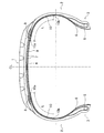
図1に示すように、本発明の空気入りタイヤは、タイヤ周方向に延在して環状をなすトレッド部1と、このトレッド部1の両側に配置された一対のサイドウォール部2と、サイドウォール部2のタイヤ径方向内側に配置された一対のビード部3とを備えている。尚、図1において、CLはタイヤ赤道を示す。
As shown in FIG. 1, the pneumatic tire of the present invention includes a tread portion 1 that extends in the tire circumferential direction and has an annular shape, a pair of
左右一対のビード部3間にはカーカス層4が装架されている。このカーカス層4は、タイヤ径方向に延びる複数本の補強コードを含み、各ビード部3に配置されたビードコア5の廻りに車両内側から外側に折り返されている。また、ビードコア5の外周上にはビードフィラー6が配置され、このビードフィラー6がカーカス層4の本体部と折り返し部とにより包み込まれている。一方、トレッド部1におけるカーカス層4の外周側には複数層(図1〜3では2層)のベルト層7が埋設されている。各ベルト層7は、タイヤ周方向に対して傾斜する複数本の補強コードを含み、かつ層間で補強コードが互いに交差するように配置されている。これらベルト層7において、補強コードのタイヤ周方向に対する傾斜角度は例えば10°〜40°の範囲に設定されている。更に、ベルト層7の外周側にはベルト補強層8が設けられている。ベルト補強層8は、タイヤ周方向に配向する有機繊維コードを含む。ベルト補強層8において、有機繊維コードはタイヤ周方向に対する角度が例えば0°〜5°に設定されている。
A
また、タイヤ内面にはインナーライナー層9が設けられている。このインナーライナー層9は空気透過防止性能を有するブチルゴムを主体とするゴム組成物で構成され、タイヤ内に充填された空気がタイヤ外に透過することを防いでいる。
An
このようなインナーライナー層9とカーカス層4との間には部分タイゴム層10が配置されている。インナーライナー層9とカーカス層4との間に配置されるタイゴム層とは、タイヤ製造時に未加硫の空気入りタイヤをインフレートする際にカーカスコードがインナーライナー層9に喰い込むことを防止するための層であり、製造後のタイヤにおいては空気透過防止性やドライ路面における操縦安定性に寄与するものであり、従来はカーカス層4とインナーライナー層9との層間の全域を覆うように設けられるものであったが(フルタイゴム層)、本発明では、部分タイゴム層10として、トレッド部1のセンター領域とビード部3とを除く領域に選択的に設けられる。即ち、図1に示すように、タイヤ赤道CLのタイヤ幅方向両側において、トレッド部1のショルダー領域とサイドウォール部2とからなる領域内にそれぞれ部分タイゴム層10が設けられている。
A partial
この部分タイゴム層10は、図2に拡大して示すように、タイヤ幅方向両側の端部(タイヤ幅方向内側の端部10aおよびタイヤ幅方向外側の端部10b)がそれぞれ部分タイゴム層10のカーカス層4側の面に対して鋭角をなす傾斜面をなしている。これら傾斜面の部分タイゴム層10のカーカス層4側の面に対する傾斜角度θはそれぞれ20°〜60°である。
As shown in an enlarged view in FIG. 2, the partial
尚、本発明において、傾斜角度θは、図3に示すように測定される。即ち、図3(a)に示すように、子午線断面において、部分タイゴム層10のカーカス層4側の面およびインナーライナー層9側の面と傾斜面とのエッジが明瞭である場合には、これらエッジどうしを結んだ線と部分タイゴム層10のカーカス層4側の面とがなす角度を傾斜角度θとする。また、図3(b)に示すように、子午線断面において、部分タイゴム層10のカーカス層4側の面と傾斜面とのエッジが不明瞭である場合には、傾斜面が直線的に延びる部分を延長した仮想線と、部分タイゴム層10のカーカス層4側の面の延長線とがなす角度を傾斜角度θとする。
In the present invention, the inclination angle θ is measured as shown in FIG. That is, as shown in FIG. 3A, in the meridian cross section, when the edges of the surface of the partial
このように部分タイゴム層10の両端部10a,10bを特定の角度を有する傾斜面に形成しているので、タイヤ製造時にタイヤ構成部材を積層する際にインナーライナー層9とカーカス層4と部分タイゴム層10の端部10a,10bとの間にエア溜まりの原因となる段差や空隙が形成されることを抑制することができ、加硫故障の発生を防止することができる。このように端部構造を特定することで加硫故障を防止しているので、部分タイゴム層10を採用することによる効果は維持することができる。即ち、フルタイゴム層を有する従来の空気入りタイヤに比べてタイヤ重量を軽減し、且つ、転がり抵抗を低減することができる。
Since both
このとき、傾斜面の傾斜方向が逆であると(傾斜面がインナーライナー層9側の面に対して鋭角をなしていると)、部分タイゴム層10の端部構造が適切でないため、エア抜け性を充分に高めることが難しくなる。また、傾斜角度θが20°よりも小さいと、部分タイゴム層10の端末が薄くなり過ぎて、タイゴム層としての機能が阻害される虞がある。傾斜角度θが60°よりも大きいと、充分な傾斜がないため、傾斜面による効果が充分に得られない。尚、傾斜角度θは好ましくは35°〜55°であるとよい。
At this time, if the inclined direction of the inclined surface is reversed (if the inclined surface forms an acute angle with respect to the surface on the
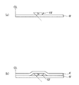
このような形状の部分タイゴム層10を備える空気入りタイヤは、例えば以下のように製造される。まず、図4(a)に示すように、未加硫のインナーライナー層9’における加硫後のタイヤのトレッド部1のセンター領域を除くタイヤ幅方向両側の領域に対応する部位にそれぞれ未加硫の部分タイゴム層10’が選択的に載置される。次いで、図4(b)に示すように、未加硫の部分タイゴム層10’を介して未加硫のインナーライナー層9’上に未加硫のカーカス層4’が積層される。この後、他のタイヤ構成部材が積層されてグリーンタイヤが成形される。そして、このグリーンタイヤを内側からブラダーで押圧しながら加硫することで、空気入りタイヤが製造される。このとき、未加硫の部分タイゴム層10’の幅方向両端部は、図示のように、それぞれ未加硫の部分タイゴム層10’の一方の面に対して鋭角をなす傾斜面となっている。そして、この傾斜面の一方の面に対する傾斜角度θ’は20°〜60°に設定されている。また、図示のように、未加硫の部分タイゴム層10’が未加硫のインナーライナー層9’上に積層される際には、一方の面が未加硫のカーカス層4’側となる向きで未加硫の部分タイゴム層10’は未加硫のインナーライナー層9’上に積層される。
A pneumatic tire including the partial
このようにすることで、図4(b)に示したように、これらタイヤ構成部材を単純に積層しただけの状態では、インナーライナー層9’とカーカス層4’と部分タイゴム層10’の端末との間に空隙が形成されているが、ブラダーで押圧しながら加硫される工程では、補強コード(カーカスコード)が埋設されたカーカス層4’よりも柔らかいインナーライナー層9’が部分タイゴム層10’の傾斜面に沿うように変形して、その際に図4(b)に示された空隙内のエアは押し出されていき、加硫後のタイヤでは図2等に示すように空隙は残存しなくなる。そのため、エア抜きが良好に行われて、エア溜まりは発生しなくなり、加硫故障を効果的に防止することができる。
In this way, as shown in FIG. 4 (b), in the state where these tire constituent members are simply laminated, the terminals of the
尚、図4の例では未加硫のインナーライナー層9’の上に未加硫の部分タイゴム層10’を載置してから順次他のタイヤ構成部材(未加硫のカーカス層4’等)を積層しているが、本発明では、未加硫のインナーライナー層9’と未加硫の部分タイゴム層10’と未加硫のカーカス層4’とが積層された状態において、未加硫の部分タイゴム層10’の幅方向両端部が、それぞれ未加硫の部分タイゴム層10’の一方の面に対して鋭角をなす傾斜面となっていればよいので、未加硫のカーカス層4’の上に未加硫の部分タイゴム層10’を載置するようにしてもよい。
In the example of FIG. 4, after placing the unvulcanized partial tie rubber layer 10 'on the unvulcanized inner liner layer 9', other tire components (unvulcanized carcass layer 4 ', etc.) In the present invention, an unvulcanized
部分タイゴム層10の物性は特に限定されないが、ゴム硬度が好ましくは50〜70、より好ましくは55〜65であるとよい。このように部分タイゴム層10の硬度を設定することで、部分タイゴム層10の形状を良好に保つことが可能になり、エア抜け性を改善して加硫故障を防止するには有利になる。このとき、ゴム硬度が50よりも小さいと、部分タイゴム層10の剛性が著しく小さいため、部分タイゴム層10の形状を維持することが難しくなり、エア抜け性が低下するため、加硫故障を充分に防止することが難しくなる。部分タイゴム層10の硬度が70よりも大きいと、サイドウォール部2の剛性が高くなり過ぎるため、空気入りタイヤの本来の性能に悪影響が出る虞がある。
The physical properties of the partial
部分タイゴム層10は、タイゴム層としての機能(タイヤ製造時におけるインナーライナー層9へのカーカスコードの喰い込みを防止すること等)を充分に発揮するために充分な厚さを有することが求められるが、その一方で、タイヤ重量の軽減のために使用量を抑えることが好ましい。また、部分タイゴム層10の形状を維持して良好なエア抜けを可能にするために適度な厚さを有することも求められる。そのため、本発明では、部分タイゴム層10の厚さTを、好ましくは0.1mm〜1.0mm、より好ましくは0.3mm〜0.7mmに設定するとよい。これにより、タイゴム層としての機能を充分に発揮しながら、タイヤ重量の軽減効果も充分に発揮することができ、更に、加硫故障にも有利になる。このとき、部分タイゴム層10の厚さTが0.1mmよりも小さいと、部分タイゴム層10が薄過ぎるため、部分タイゴム層10がタイゴム層として充分に機能しなくなり、タイヤ製造時におけるインナーライナー層9へのカーカスコードの喰い込みを防止する効果が限定的になる。また、部分タイゴム層10の形状維持が難しくなり、エア抜け性が低下するため、加硫故障を充分に防止することが難しくなる。部分タイゴム層10の厚さTが1.0mmよりも大きいと、部分タイゴム層10が厚くなり過ぎて使用量が増大するため、タイヤ重量の軽減効果が限定的になる。
The partial
部分タイゴム層10は、前述のように、タイヤ製造時におけるインナーライナー層9へのカーカスコードの喰い込みを防止するものであるので、カーカス層4とインナーライナー層9との間の適度な領域を覆うことが好ましい。そのため、本発明では、部分タイゴム層10のペリフェリ長さを、好ましくは30mm〜120mm、より好ましくは40mm〜80mmにするとよい。これにより、部分タイゴム層10のペリフェリ長さを最適化することができ、タイゴム層としての機能とタイヤ重量や転がり抵抗の低減とをバランスよく両立するには有利になる。このとき、部分タイゴム層10のペリフェリ長さL3が30mmよりも小さいと、部分タイゴム層10によってカーカス層4とインナーライナー層9との間の適度な領域を覆うことが難しくなり、タイゴム層としての機能を充分に発揮することが難しくなる。部分タイゴム層10のペリフェリ長さL3が120mmよりも大きいと、部分タイゴム層10の使用量が増加するため、タイヤ重量の軽減効果が限定的になる。
As described above, the partial
タイヤサイズが195/65R15であり、図1に示す基本構造を有し、タイゴム層の構造、部分タイゴム層の端部に形成された傾斜面の傾斜角度θ、部分タイゴム層のゴム硬度、部分タイゴム層のゴム厚さ、部分タイゴム層のペリフェリ長さをそれぞれ表1〜2のように設定した従来例1、比較例1〜4、実施例1〜16の21種類の空気入りタイヤを作製した。 The tire size is 195 / 65R15, and has the basic structure shown in FIG. 1. The structure of the tie rubber layer, the inclination angle θ of the inclined surface formed at the end of the partial tie rubber layer, the rubber hardness of the partial tie rubber layer, and the partial tie rubber 21 types of pneumatic tires of Conventional Example 1, Comparative Examples 1 to 4, and Examples 1 to 16, in which the rubber thickness of the layer and the peripheral length of the partial tie rubber layer were set as shown in Tables 1 and 2 were prepared.
尚、表1〜2の「タイゴム層の構造」の欄について、タイゴム層がフルタイゴム層である場合は「フル」、部分タイゴム層である場合は「部分」と記載した。 In the column of “structure of tie rubber layer” in Tables 1 and 2, “full” was described when the tie rubber layer was a full tie rubber layer, and “part” when it was a partial tie rubber layer.
これら21種類の空気入りタイヤについて、下記の評価方法により、タイゴム使用量、空気透過防止性、ドライ路面における操縦安定性(操縦安定性)を評価し、その結果を表1〜5に併せて示した。 About these 21 types of pneumatic tires, the amount of tie rubber used, the air permeation prevention property, and the steering stability on the dry road surface (steering stability) were evaluated by the following evaluation methods, and the results are also shown in Tables 1 to 5. It was.
タイゴム使用量
各試験タイヤにおけるタイゴムの使用量を測定した。評価結果は、従来例1の測定値を100とする指数にて示した。この指数値が小さいほどタイゴム使用量が少なく、タイヤ重量を軽減できることを意味する。尚、この指数値が「85」以下であると、タイゴム使用量が充分に少ないと言え、優れたタイヤ重量の軽減効果が得られている。逆に、この指数値が「85」を超えると、タイゴム使用量は充分に低減できておらず、タイヤ重量の軽減効果は実質的に得られていないことになる。特に、この指数値が「70」以下であると、タイヤ重量の軽減効果が大きく優れている。
Amount of tie rubber used The amount of tie rubber used in each test tire was measured. The evaluation results are shown as an index with the measured value of Conventional Example 1 being 100. The smaller the index value, the smaller the amount of tie rubber used, which means that the tire weight can be reduced. When the index value is “85” or less, it can be said that the amount of tie rubber used is sufficiently small, and an excellent tire weight reduction effect is obtained. On the contrary, if this index value exceeds “85”, the amount of tie rubber used cannot be sufficiently reduced, and the tire weight reducing effect is not substantially obtained. In particular, when the index value is “70” or less, the effect of reducing the tire weight is greatly excellent.
転がり抵抗
各試験タイヤを、リムサイズ15×6Jのホイールに組み付け、ISO28580に準拠して、ドラム径1707.6mmのドラム試験機を用い、空気圧210kPa、荷重4.82kN、速度80km/hの条件で転がり抵抗を測定した。評価結果は、従来例1の測定値の逆数を100とする指数にて示した。この指数値が大きいほど転がり抵抗が低いことを意味する。
Rolling resistance Each test tire is assembled on a wheel with a rim size of 15 × 6J, and in accordance with ISO28580, using a drum testing machine with a drum diameter of 1707.6 mm, rolling under conditions of air pressure 210 kPa, load 4.82 kN, speed 80 km / h. Resistance was measured. The evaluation results are shown as an index with the reciprocal of the measured value of Conventional Example 1 being 100. It means that rolling resistance is so low that this index value is large.
故障発生率
各試験タイヤをそれぞれ100本ずつ製造し、成形・加硫後のタイヤの内面を観察し、成形・加硫工程での内面故障の有無を目視で確認し、故障発生率(各試験タイヤの総数に対する内面故障が発生したタイヤの本数の割合)を測定した。評価結果は、従来例1の測定値の逆数を100とする指数にて示した。この指数値が大きいほど内面故障の発生率が小さいことを意味する。
Failure occurrence rate 100 test tires were manufactured for each, and the inner surface of the molded and vulcanized tire was observed, and whether there was an inner surface failure during the molding and vulcanization process was visually confirmed. The ratio of the number of tires having an internal failure to the total number of tires) was measured. The evaluation results are shown as an index with the reciprocal of the measured value of Conventional Example 1 being 100. A larger index value means a lower incidence of internal failure.

表1〜2から明らかなように、実施例1〜16はいずれも、従来例1に対して、タイゴム使用量を低減し、転がり抵抗を低減すると共に、故障発生率を改善した。 As is clear from Tables 1 and 2, all of Examples 1 to 16 reduced the amount of tie rubber used, reduced rolling resistance, and improved the failure rate relative to Conventional Example 1.
一方、比較例1は、傾斜角度θが90°であり、部分タイゴム層の端末が傾斜していないので、傾斜面によるエア抜け性の改善は見込めず、故障発生率が悪化した。比較例2は、傾斜角度θが135°であり、部分タイゴム層の向きが逆転しているので、傾斜面によるエア抜け性の改善は見込めず、故障発生率が悪化した。比較例3は、傾斜角度θが小さ過ぎるため、故障発生率を充分に維持することができなかった。比較例4は、傾斜角度θが大き過ぎるため、実質的に比較例1と同等であり、故障発生率を改善することはできなかった。 On the other hand, in Comparative Example 1, since the inclination angle θ is 90 ° and the end of the partial tie rubber layer is not inclined, the improvement of the air escape property due to the inclined surface cannot be expected, and the failure occurrence rate deteriorated. In Comparative Example 2, since the inclination angle θ is 135 ° and the direction of the partial tie rubber layer is reversed, the improvement of the air escape property due to the inclined surface cannot be expected, and the failure occurrence rate deteriorated. In Comparative Example 3, since the inclination angle θ was too small, the failure occurrence rate could not be sufficiently maintained. In Comparative Example 4, since the inclination angle θ is too large, it is substantially equivalent to Comparative Example 1, and the failure occurrence rate could not be improved.
1 トレッド部
2 サイドウォール部
3 ビード部
4 カーカス層
5 ビードコア
6 ビードフィラー
7 ベルト層
8 ベルト補強層
9 インナーライナー層
10 部分タイゴム層
CL タイヤ赤道
DESCRIPTION OF SYMBOLS 1
本発明は、カーカス層とインナーライナー層との層間の一部に選択的に配置される部分タイゴム層を備えた空気入りタイヤの製造方法に関し、更に詳しくは、部分タイゴム層を採用した場合に懸念される加硫故障を防止し、且つ、部分タイゴム層を採用することによるタイヤ重量や転がり抵抗の低減を充分に発揮することを可能にした空気入りタイヤの製造方法に関する。 The present invention relates to a method of manufacturing a selectively placed pneumatic tire having a partial tie rubber layer is in a part of the interlayer between the carcass layer and the inner liner layer, more particularly, in the case of employing the partial tie rubber layer preventing concerned vulcanization failure, and relates to a method of manufacturing a pneumatic tire which makes it possible to sufficiently exhibit a reduction in tire weight and rolling resistance by adopting the partial tie rubber layer.
本発明の目的は、部分タイゴム層を採用した場合に懸念される加硫故障を防止し、且つ、部分タイゴム層を採用することによるタイヤ重量や転がり抵抗の低減を充分に発揮することを可能にした空気入りタイヤの製造方法を提供することにある。 An object of the present invention is to prevent a vulcanization failure which is a concern when a partial tie rubber layer is employed, and to sufficiently exhibit reduction in tire weight and rolling resistance due to the adoption of a partial tie rubber layer. It is to provide a the manufacturing method of a pneumatic tire.
上記目的を達成するための本発明の空気入りタイヤの製造方法は、未加硫のインナーライナー層またはカーカス層における加硫後のタイヤのトレッド部のセンター領域を除くタイヤ幅方向両側の領域に対応する部位にそれぞれ未加硫の部分タイゴム層が選択的に載置され、該未加硫の部分タイゴム層を介して前記未加硫のインナーライナー層上に未加硫のカーカス層が積層されたグリーンタイヤを成形し、該グリーンタイヤを内側からブラダーで押圧しながら加硫する空気入りタイヤの製造方法において、前記部分タイゴム層を構成するゴムの硬度を50〜70とし、前記未加硫の部分タイゴム層の幅方向両端部にそれぞれ前記未加硫の部分タイゴム層の一方の面に対して鋭角をなす傾斜面を形成し、該傾斜面の前記一方の面に対する傾斜角度を35°〜55°とし、前記一方の面が前記未加硫のカーカス層側となる向きで前記未加硫の部分タイゴム層を前記未加硫のインナーライナー層と前記未加硫のカーカス層との間に積層することを特徴とする。 The pneumatic tire manufacturing method of the present invention for achieving the above Symbol purpose, the area of the tire width direction on both sides except for the center region of the tread portion of the tire after vulcanization in the uncured inner liner layer or a carcass layer An unvulcanized partial tie rubber layer is selectively placed on the corresponding part, and an unvulcanized carcass layer is laminated on the unvulcanized inner liner layer via the unvulcanized partial tie rubber layer. In the method of manufacturing a pneumatic tire in which a green tire is molded and vulcanized while pressing the green tire with a bladder from the inside , the hardness of the rubber constituting the partial tie rubber layer is 50 to 70, and the unvulcanized tire An inclined surface forming an acute angle with respect to one surface of the unvulcanized partial tie rubber layer is formed at each of both ends in the width direction of the partial tie rubber layer, and the inclined angle of the inclined surface with respect to the one surface Was a 35 ° to 55 °, the unvulcanized inner liner layer and the unvulcanized carcass layer the unvulcanized portions tie rubber layer in the direction in which the the one surface becomes a carcass layer side of the unvulcanized It is characterized by being laminated between.
本発明によって製造される空気入りタイヤでは、部分タイゴム層を採用して、フルタイゴム層を有する従来の空気入りタイヤに比べてタイヤ重量を軽減し、転がり抵抗を低減するにあたって、部分タイゴム層の端部を上述のように特定の角度を有する傾斜面に形成しているので、タイヤ製造時にタイヤ構成部材を積層する際にインナーライナー層とカーカス層と部分タイゴム層の端部との間にエア溜まりの原因となる段差や空隙が形成されることを抑制することができ、加硫故障の発生を防止することができる。 The pneumatic tire manufactured according to the present invention employs a partial tie rubber layer to reduce the tire weight and reduce rolling resistance as compared with a conventional pneumatic tire having a full tie rubber layer. Is formed on an inclined surface having a specific angle as described above, so that when the tire constituent members are laminated at the time of manufacturing the tire, there is an air pool between the inner liner layer, the carcass layer, and the end of the partial tie rubber layer. It is possible to suppress the formation of steps and gaps that cause the occurrence of vulcanization failure.
本発明においては、部分タイゴム層を構成するゴムの硬度が50〜70であるので、部分タイゴム層の形状を良好に保つことが可能になり、エア抜け性を改善して加硫故障を防止するには有利になる。尚、本発明における「ゴムの硬度」とは、JIS K6253に準拠しデュロメータのタイプAにより温度20℃で測定された硬さ(所謂、JIS‐A硬度)である。 In the present invention, since the hardness of the rubber constituting the partial tie rubber layer is 50 to 70, it is possible to maintain the shape of the portion tie rubber layer satisfactorily prevents vulcanization failure to improve the air removability Is advantageous. The “rubber hardness” in the present invention is a hardness (so-called JIS-A hardness) measured at a temperature of 20 ° C. by a durometer type A in accordance with JIS K6253.
図1に示すように、本発明によって製造される空気入りタイヤは、タイヤ周方向に延在して環状をなすトレッド部1と、このトレッド部1の両側に配置された一対のサイドウォール部2と、サイドウォール部2のタイヤ径方向内側に配置された一対のビード部3とを備えている。尚、図1において、CLはタイヤ赤道を示す。
As shown in FIG. 1, a pneumatic tire manufactured according to the present invention includes a tread portion 1 that extends in the tire circumferential direction and has an annular shape, and a pair of
この部分タイゴム層10は、図2に拡大して示すように、タイヤ幅方向両側の端部(タイヤ幅方向内側の端部10aおよびタイヤ幅方向外側の端部10b)がそれぞれ部分タイゴム層10のカーカス層4側の面に対して鋭角をなす傾斜面をなしている。これら傾斜面の部分タイゴム層10のカーカス層4側の面に対する傾斜角度θはそれぞれ少なくとも20°〜60°に設定されるが、本発明では特に35°〜55°に設定される。
As shown in an enlarged view in FIG. 2, the partial
このとき、傾斜面の傾斜方向が逆であると(傾斜面がインナーライナー層9側の面に対して鋭角をなしていると)、部分タイゴム層10の端部構造が適切でないため、エア抜け性を充分に高めることが難しくなる。また、傾斜角度θが20°よりも小さいと、部分タイゴム層10の端末が薄くなり過ぎて、タイゴム層としての機能が阻害される虞がある。傾斜角度θが60°よりも大きいと、充分な傾斜がないため、傾斜面による効果が充分に得られない。
At this time, if the inclined direction of the inclined surface is reversed (if the inclined surface forms an acute angle with respect to the surface on the
このような形状の部分タイゴム層10を備える空気入りタイヤは、以下のように製造される。まず、図4(a)に示すように、未加硫のインナーライナー層9’における加硫後のタイヤのトレッド部1のセンター領域を除くタイヤ幅方向両側の領域に対応する部位にそれぞれ未加硫の部分タイゴム層10’が選択的に載置される。次いで、図4(b)に示すように、未加硫の部分タイゴム層10’を介して未加硫のインナーライナー層9’上に未加硫のカーカス層4’が積層される。この後、他のタイヤ構成部材が積層されてグリーンタイヤが成形される。そして、このグリーンタイヤを内側からブラダーで押圧しながら加硫することで、空気入りタイヤが製造される。このとき、未加硫の部分タイゴム層10’の幅方向両端部は、図示のように、それぞれ未加硫の部分タイゴム層10’の一方の面に対して鋭角をなす傾斜面となっている。そして、この傾斜面の一方の面に対する傾斜角度θ’は35°〜55°に設定されている。また、図示のように、未加硫の部分タイゴム層10’が未加硫のインナーライナー層9’上に積層される際には、一方の面が未加硫のカーカス層4’側となる向きで未加硫の部分タイゴム層10’は未加硫のインナーライナー層9’上に積層される。
A pneumatic tire provided with a partial
部分タイゴム層10の物性としては、ゴム硬度が50〜70、好ましくは55〜65である。このように部分タイゴム層10の硬度を設定することで、部分タイゴム層10の形状を良好に保つことが可能になり、エア抜け性を改善して加硫故障を防止するには有利になる。このとき、ゴム硬度が50よりも小さいと、部分タイゴム層10の剛性が著しく小さいため、部分タイゴム層10の形状を維持することが難しくなり、エア抜け性が低下するため、加硫故障を充分に防止することが難しくなる。部分タイゴム層10の硬度が70よりも大きいと、サイドウォール部2の剛性が高くなり過ぎるため、空気入りタイヤの本来の性能に悪影響が出る虞がある。
The physical properties of the partial
タイヤサイズが195/65R15であり、図1に示す基本構造を有し、タイゴム層の構造、部分タイゴム層の端部に形成された傾斜面の傾斜角度θ、部分タイゴム層のゴム硬度、部分タイゴム層のゴム厚さ、部分タイゴム層のペリフェリ長さをそれぞれ表1〜2のように設定した従来例1、比較例1〜8、実施例1〜12の21種類の空気入りタイヤを作製した。 The tire size is 195 / 65R15, and has the basic structure shown in FIG. 1. The structure of the tie rubber layer, the inclination angle θ of the inclined surface formed at the end of the partial tie rubber layer, the rubber hardness of the partial tie rubber layer, and the partial tie rubber 21 types of pneumatic tires of Conventional Example 1, Comparative Examples 1 to 8 and Examples 1 to 12 , in which the rubber thickness of the layer and the peripheral length of the partial tie rubber layer were respectively set as shown in Tables 1 and 2 were produced.
これら21種類の空気入りタイヤについて、下記の評価方法により、タイゴム使用量、空気透過防止性、ドライ路面における操縦安定性(操縦安定性)を評価し、その結果を表1〜2に併せて示した。 About these 21 types of pneumatic tires, the following evaluation methods were used to evaluate the amount of tie rubber used, air permeation prevention, and steering stability (steering stability) on dry road surfaces. The results are also shown in Tables 1-2. It was.
表1〜2から明らかなように、実施例1〜12はいずれも、従来例1に対して、タイゴム使用量を低減し、転がり抵抗を低減すると共に、故障発生率を改善した。 As is clear from Tables 1 and 2, all of Examples 1 to 12 reduced the amount of tie rubber used, reduced rolling resistance, and improved the failure rate compared to Conventional Example 1.
Claims (5)
前記部分タイゴム層のタイヤ幅方向両側の端部がそれぞれ前記部分タイゴム層の前記カーカス層側の面に対して鋭角をなす傾斜面をなし、該傾斜面の前記部分タイゴム層の前記カーカス層側の面に対する傾斜角度が20°〜60°であることを特徴とする空気入りタイヤ。 An annular tread portion extending in the tire circumferential direction, a pair of sidewall portions disposed on both sides of the tread portion, and a pair of bead portions disposed on the inner side in the tire radial direction of the sidewall portions. A carcass layer mounted between the pair of bead portions; a belt layer disposed on an outer peripheral side of the carcass layer in the tread portion; and an inner liner layer disposed on a tire inner surface along the carcass layer And a partial tie rubber layer selectively disposed in each of the regions on the both sides in the tire width direction excluding the center region of the tread portion between the carcass layer and the inner liner layer. ,
The ends of the partial tie rubber layer on both sides in the tire width direction form inclined surfaces that form an acute angle with respect to the surface of the partial tie rubber layer on the carcass layer side, and the inclined tie rubber layer on the carcass layer side of the partial tie rubber layer A pneumatic tire having an inclination angle with respect to a surface of 20 ° to 60 °.
前記未加硫の部分タイゴム層の幅方向両端部にそれぞれ前記未加硫の部分タイゴム層の一方の面に対して鋭角をなす傾斜面を形成し、該傾斜面の前記一方の面に対する傾斜角度を20°〜60°とし、前記一方の面が前記未加硫のカーカス層側となる向きで前記未加硫の部分タイゴム層を前記未加硫のインナーライナー層と前記未加硫のカーカス層との間に積層することを特徴とする空気入りタイヤの製造方法。 Unvulcanized partial tie rubber layers are selectively placed on the portions corresponding to the regions on both sides of the tire width direction excluding the center region of the tire tread after vulcanization in the unvulcanized inner liner layer or carcass layer. Then, a green tire in which an unvulcanized carcass layer is laminated on the unvulcanized inner liner layer through the unvulcanized partial tie rubber layer is molded, and the green tire is vulcanized while being pressed from the inside with a bladder. In the manufacturing method of the pneumatic tire to be vulcanized,
An inclined surface that forms an acute angle with respect to one surface of the unvulcanized partial tie rubber layer is formed at each of both end portions in the width direction of the unvulcanized partial tie rubber layer, and the inclined angle of the inclined surface with respect to the one surface Of the unvulcanized partial tie rubber layer with the uncured inner liner layer and the uncured carcass layer in a direction in which the one surface is on the uncured carcass layer side. A method for manufacturing a pneumatic tire, comprising:
Priority Applications (6)
| Application Number | Priority Date | Filing Date | Title |
|---|---|---|---|
| JP2016049740A JP6304291B2 (en) | 2016-03-14 | 2016-03-14 | Pneumatic tire manufacturing method |
| DE112017001294.5T DE112017001294T5 (en) | 2016-03-14 | 2017-02-20 | Pneumatic tires and method of making same |
| US16/084,953 US11453187B2 (en) | 2016-03-14 | 2017-02-20 | Pneumatic tire and method for manufacturing same |
| CN201780016826.9A CN108778779B (en) | 2016-03-14 | 2017-02-20 | Pneumatic tire and method for manufacturing same |
| KR1020187029438A KR102132667B1 (en) | 2016-03-14 | 2017-02-20 | Pneumatic tire and its manufacturing method |
| PCT/JP2017/006117 WO2017159220A1 (en) | 2016-03-14 | 2017-02-20 | Pneumatic tire and method for producing same |
Applications Claiming Priority (1)
| Application Number | Priority Date | Filing Date | Title |
|---|---|---|---|
| JP2016049740A JP6304291B2 (en) | 2016-03-14 | 2016-03-14 | Pneumatic tire manufacturing method |
Publications (2)
| Publication Number | Publication Date |
|---|---|
| JP2017165135A true JP2017165135A (en) | 2017-09-21 |
| JP6304291B2 JP6304291B2 (en) | 2018-04-04 |
Family
ID=59852181
Family Applications (1)
| Application Number | Title | Priority Date | Filing Date |
|---|---|---|---|
| JP2016049740A Expired - Fee Related JP6304291B2 (en) | 2016-03-14 | 2016-03-14 | Pneumatic tire manufacturing method |
Country Status (6)
| Country | Link |
|---|---|
| US (1) | US11453187B2 (en) |
| JP (1) | JP6304291B2 (en) |
| KR (1) | KR102132667B1 (en) |
| CN (1) | CN108778779B (en) |
| DE (1) | DE112017001294T5 (en) |
| WO (1) | WO2017159220A1 (en) |
Cited By (2)
| Publication number | Priority date | Publication date | Assignee | Title |
|---|---|---|---|---|
| EP3611036A1 (en) * | 2018-08-15 | 2020-02-19 | Continental Reifen Deutschland GmbH | Commercial vehicle tyres |
| JP7315818B2 (en) | 2019-03-18 | 2023-07-27 | 横浜ゴム株式会社 | pneumatic tire |
Families Citing this family (1)
| Publication number | Priority date | Publication date | Assignee | Title |
|---|---|---|---|---|
| JP6424919B2 (en) * | 2017-04-19 | 2018-11-21 | 横浜ゴム株式会社 | Pneumatic tire and method of manufacturing the same |
Citations (5)
| Publication number | Priority date | Publication date | Assignee | Title |
|---|---|---|---|---|
| JPH115261A (en) * | 1997-06-18 | 1999-01-12 | Yokohama Rubber Co Ltd:The | Manufacture of pneumatic tire |
| WO2005007423A1 (en) * | 2003-07-17 | 2005-01-27 | The Yokohama Rubber Co., Ltd. | Pneumatic tire with improved durability |
| JP2009279974A (en) * | 2008-05-19 | 2009-12-03 | Yokohama Rubber Co Ltd:The | Pneumatic tire |
| JP5723086B2 (en) * | 2009-05-12 | 2015-05-27 | 住友ゴム工業株式会社 | Pneumatic tire |
| JP2015174594A (en) * | 2014-03-17 | 2015-10-05 | 住友ゴム工業株式会社 | pneumatic tire |
Family Cites Families (9)
| Publication number | Priority date | Publication date | Assignee | Title |
|---|---|---|---|---|
| US3682221A (en) * | 1969-03-14 | 1972-08-08 | Alfred Marzocchi | Tire construction with improved reinforcement |
| JPS5239507B2 (en) | 1973-06-15 | 1977-10-05 | ||
| JPS5723086B2 (en) * | 1974-03-20 | 1982-05-17 | ||
| GB9801224D0 (en) * | 1998-01-21 | 1998-03-18 | Sumitomo Rubber Ind | Improvements to tyres |
| EP1524132B1 (en) * | 1998-12-17 | 2012-04-18 | Bridgestone Corporation | Pneumatic tire |
| EP1623821B1 (en) * | 2004-08-03 | 2007-10-03 | Sumitomo Rubber Industries, Ltd. | Manufacturing method of a rubber member for tire |
| US20110139328A1 (en) * | 2008-08-11 | 2011-06-16 | Pirelli Tyre S.P.A. | Process for building green tyre for vehicle wheels and tyres built by said process |
| DE102008038764A1 (en) * | 2008-08-12 | 2010-02-18 | Continental Reifen Deutschland Gmbh | Vehicle tires |
| US8413700B2 (en) * | 2010-02-04 | 2013-04-09 | Bridgestone Americas Tire Operations, Llc | Tire having staggered turn-ups |
-
2016
- 2016-03-14 JP JP2016049740A patent/JP6304291B2/en not_active Expired - Fee Related
-
2017
- 2017-02-20 KR KR1020187029438A patent/KR102132667B1/en active IP Right Grant
- 2017-02-20 US US16/084,953 patent/US11453187B2/en active Active
- 2017-02-20 CN CN201780016826.9A patent/CN108778779B/en active Active
- 2017-02-20 DE DE112017001294.5T patent/DE112017001294T5/en active Pending
- 2017-02-20 WO PCT/JP2017/006117 patent/WO2017159220A1/en active Application Filing
Patent Citations (6)
| Publication number | Priority date | Publication date | Assignee | Title |
|---|---|---|---|---|
| JPH115261A (en) * | 1997-06-18 | 1999-01-12 | Yokohama Rubber Co Ltd:The | Manufacture of pneumatic tire |
| WO2005007423A1 (en) * | 2003-07-17 | 2005-01-27 | The Yokohama Rubber Co., Ltd. | Pneumatic tire with improved durability |
| JP2009279974A (en) * | 2008-05-19 | 2009-12-03 | Yokohama Rubber Co Ltd:The | Pneumatic tire |
| JP5239507B2 (en) * | 2008-05-19 | 2013-07-17 | 横浜ゴム株式会社 | Pneumatic tire |
| JP5723086B2 (en) * | 2009-05-12 | 2015-05-27 | 住友ゴム工業株式会社 | Pneumatic tire |
| JP2015174594A (en) * | 2014-03-17 | 2015-10-05 | 住友ゴム工業株式会社 | pneumatic tire |
Cited By (2)
| Publication number | Priority date | Publication date | Assignee | Title |
|---|---|---|---|---|
| EP3611036A1 (en) * | 2018-08-15 | 2020-02-19 | Continental Reifen Deutschland GmbH | Commercial vehicle tyres |
| JP7315818B2 (en) | 2019-03-18 | 2023-07-27 | 横浜ゴム株式会社 | pneumatic tire |
Also Published As
| Publication number | Publication date |
|---|---|
| CN108778779B (en) | 2020-10-13 |
| WO2017159220A1 (en) | 2017-09-21 |
| DE112017001294T5 (en) | 2018-12-06 |
| JP6304291B2 (en) | 2018-04-04 |
| US11453187B2 (en) | 2022-09-27 |
| CN108778779A (en) | 2018-11-09 |
| KR20180120764A (en) | 2018-11-06 |
| US20190077105A1 (en) | 2019-03-14 |
| KR102132667B1 (en) | 2020-07-10 |
Similar Documents
| Publication | Publication Date | Title |
|---|---|---|
| JP6304291B2 (en) | Pneumatic tire manufacturing method | |
| JP5211707B2 (en) | Rehabilitated tire and tire rehabilitation method | |
| US10308082B2 (en) | Run-flat tire | |
| JP6135719B2 (en) | Pneumatic tire | |
| US20060185780A1 (en) | Pneumatic tire for passenger cars | |
| EP2671729A1 (en) | Pneumatic tire and method for manufacturing same | |
| JP2005193758A (en) | Pneumatic tire | |
| JP2007216634A (en) | Reclaimed tire and manufacturing method of the same | |
| WO2018193865A1 (en) | Pneumatic tire and method for manufacturing same | |
| JP2021116043A (en) | Pneumatic radial tire, pneumatic radial tire manufacturing method, and tire vulcanization die | |
| JP6376210B2 (en) | Pneumatic tire | |
| JP5084255B2 (en) | Manufacturing method of pneumatic radial tire | |
| KR101566183B1 (en) | Bladder of Tire Vulcanizing | |
| JP2011255858A (en) | Pneumatic tire and method for manufacturing the same | |
| KR101982844B1 (en) | Pneumatic tire | |
| JP2014189050A (en) | Pneumatic tire | |
| JP6838366B2 (en) | How to make a pneumatic tire | |
| JP6690487B2 (en) | Pneumatic tire | |
| JP2018008619A (en) | Pneumatic tire | |
| JP2014080160A (en) | Pneumatic radial tire and method for manufacturing the same | |
| JP2008037156A (en) | Pneumatic tire and manufacturing method thereof | |
| JP2004034613A (en) | Method for manufacturing pneumatic radial tire and pneumatic radial tire manufactured by the method | |
| JP2004224112A (en) | Pneumatic tire and its manufacturing method | |
| JP2014080161A (en) | Pneumatic radial tire and method for manufacturing the same | |
| JP2012121150A (en) | Method for producing emergency tire, and tire |
Legal Events
| Date | Code | Title | Description |
|---|---|---|---|
| A521 | Request for written amendment filed |
Free format text: JAPANESE INTERMEDIATE CODE: A523 Effective date: 20170713 |
|
| A02 | Decision of refusal |
Free format text: JAPANESE INTERMEDIATE CODE: A02 Effective date: 20171003 |
|
| A521 | Request for written amendment filed |
Free format text: JAPANESE INTERMEDIATE CODE: A523 Effective date: 20171227 |
|
| A911 | Transfer to examiner for re-examination before appeal (zenchi) |
Free format text: JAPANESE INTERMEDIATE CODE: A911 Effective date: 20180109 |
|
| TRDD | Decision of grant or rejection written | ||
| A01 | Written decision to grant a patent or to grant a registration (utility model) |
Free format text: JAPANESE INTERMEDIATE CODE: A01 Effective date: 20180206 |
|
| A61 | First payment of annual fees (during grant procedure) |
Free format text: JAPANESE INTERMEDIATE CODE: A61 Effective date: 20180219 |
|
| R150 | Certificate of patent or registration of utility model |
Ref document number: 6304291 Country of ref document: JP Free format text: JAPANESE INTERMEDIATE CODE: R150 |
|
| R250 | Receipt of annual fees |
Free format text: JAPANESE INTERMEDIATE CODE: R250 |
|
| LAPS | Cancellation because of no payment of annual fees |