JP5723086B2 - Pneumatic tire - Google Patents
Pneumatic tire Download PDFInfo
- Publication number
- JP5723086B2 JP5723086B2 JP2009115721A JP2009115721A JP5723086B2 JP 5723086 B2 JP5723086 B2 JP 5723086B2 JP 2009115721 A JP2009115721 A JP 2009115721A JP 2009115721 A JP2009115721 A JP 2009115721A JP 5723086 B2 JP5723086 B2 JP 5723086B2
- Authority
- JP
- Japan
- Prior art keywords
- tire
- groove
- carcass
- shoulder
- tread
- Prior art date
- Legal status (The legal status is an assumption and is not a legal conclusion. Google has not performed a legal analysis and makes no representation as to the accuracy of the status listed.)
- Active
Links
- 229920001971 elastomer Polymers 0.000 claims description 55
- 239000005060 rubber Substances 0.000 claims description 55
- 239000011324 bead Substances 0.000 claims description 18
- 238000004804 winding Methods 0.000 claims description 3
- 238000004519 manufacturing process Methods 0.000 description 7
- 238000012360 testing method Methods 0.000 description 6
- 239000000835 fiber Substances 0.000 description 3
- -1 for example Polymers 0.000 description 3
- 239000000203 mixture Substances 0.000 description 3
- 229920000297 Rayon Polymers 0.000 description 2
- 229910000831 Steel Inorganic materials 0.000 description 2
- 239000004760 aramid Substances 0.000 description 2
- 229920003235 aromatic polyamide Polymers 0.000 description 2
- 229920005549 butyl rubber Polymers 0.000 description 2
- 230000000052 comparative effect Effects 0.000 description 2
- 239000000463 material Substances 0.000 description 2
- 229920000642 polymer Polymers 0.000 description 2
- 239000002964 rayon Substances 0.000 description 2
- 239000010959 steel Substances 0.000 description 2
- 229920001875 Ebonite Polymers 0.000 description 1
- 244000043261 Hevea brasiliensis Species 0.000 description 1
- 239000004677 Nylon Substances 0.000 description 1
- 238000013459 approach Methods 0.000 description 1
- 229920005557 bromobutyl Polymers 0.000 description 1
- 229920005556 chlorobutyl Polymers 0.000 description 1
- 238000007796 conventional method Methods 0.000 description 1
- 238000013461 design Methods 0.000 description 1
- 230000006866 deterioration Effects 0.000 description 1
- 238000009826 distribution Methods 0.000 description 1
- 238000000034 method Methods 0.000 description 1
- 229920003052 natural elastomer Polymers 0.000 description 1
- 229920001194 natural rubber Polymers 0.000 description 1
- 229920001778 nylon Polymers 0.000 description 1
- 229920000728 polyester Polymers 0.000 description 1
- 230000001105 regulatory effect Effects 0.000 description 1
- 238000005096 rolling process Methods 0.000 description 1
- 238000000926 separation method Methods 0.000 description 1
- 238000010998 test method Methods 0.000 description 1
Images

Description
本発明は、カーカスとインナーライナとの間に配されるタイゴムの外端位置を規制することにより、重量増加を防止しつつ、ユニフォミティの低下を抑制しうる空気入りタイヤに関する。 The present invention relates to a pneumatic tire that can suppress a decrease in uniformity while preventing an increase in weight by regulating an outer end position of a tie rubber disposed between a carcass and an inner liner.
従来、チューブレスタイプの空気入りタイヤでは、転動時のタイヤの変形等により、タイヤ内腔面をなすインナーライナが、その外側に配されるカーカスプライのカーカスコード間にめり込み、その部分でセパレーション等の損傷が生じ易いという問題があった。このような問題を解決すべく、カーカスとインナーライナとの間に、例えばカーカスコードとの接着性に優れたゴム材からなるタイゴムが配された空気入りタイヤが提案されている(例えば、特許文献1参照)。このようなタイゴムは、接着性の低いインナーライナとカーカスコードとの直接接触を防ぎ、耐久性を向上させる。 Conventionally, in tubeless type pneumatic tires, due to deformation of the tire during rolling, the inner liner that forms the inner surface of the tire is indented between the carcass cords of the carcass ply arranged on the outer side, and separation is performed at that portion. There was a problem that the damage was likely to occur. In order to solve such problems, there has been proposed a pneumatic tire in which a tie rubber made of a rubber material having excellent adhesion to a carcass cord, for example, is disposed between a carcass and an inner liner (for example, Patent Documents). 1). Such a tie rubber prevents direct contact between the inner liner having low adhesiveness and the carcass cord, and improves durability.
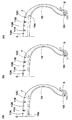
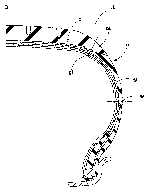
また、図5に示されるように、タイヤ転動時に比較的変形の大きいベルト層bの端部btからタイヤ最大幅部wまでのバットレス領域cに、タイゴムgが配された空気入りタイヤtが提案されている(例えば、特許文献2参照)。この空気入りタイヤtは、タイゴムgの使用領域を減じ、重量増加を抑制するのに役立つ。 Further, as shown in FIG. 5, the pneumatic tire t in which the tie rubber g is arranged in the buttress region c from the end bt of the belt layer b that is relatively deformed when the tire rolls to the tire maximum width w. It has been proposed (see, for example, Patent Document 2). This pneumatic tire t is useful for reducing the use area of the tie rubber g and suppressing the weight increase.
しかしながら、タイヤ製造工程において、例えば、タイゴムgのタイヤ半径方向の外端gtの位置は、タイヤ半径方向にばらつきやすい。そして、タイゴムgの外端gtの位置のバラツキは、厚さが比較的小さいバットレス領域cの重量分布の不均一性に大きな影響を与え、タイヤのユニフォミティが大幅に低下するという問題があった。 However, in the tire manufacturing process, for example, the position of the outer end gt of the tie rubber g in the tire radial direction tends to vary in the tire radial direction. The variation in the position of the outer end gt of the tie rubber g has a problem that the uniformity of the tire is greatly lowered due to the large influence on the non-uniformity of the weight distribution of the buttress region c having a relatively small thickness.
本発明は、以上のような実状に鑑み案出されたもので、各タイゴムのタイヤ半径方向の外端を、トレッド部のショルダー縦溝とミドル縦溝との間のミドル陸部のタイヤ半径方向内方で終端させることを基本として、重量増加を防止しつつ、ユニフォミティの低下を抑制しうる空気入りタイヤを提供することを主たる目的としている。 The present invention has been devised in view of the actual situation as described above, and the outer end of each tie rubber in the tire radial direction is arranged in the tire radial direction of the middle land portion between the shoulder vertical groove and the middle vertical groove of the tread portion. The main purpose is to provide a pneumatic tire capable of suppressing a decrease in uniformity while preventing an increase in weight, based on termination inward.
本発明のうち請求項1記載の発明は、トレッド部からサイドウォール部をへてビード部のビードコアに至るカーカスと、前記カーカスのタイヤ半径方向外側かつ前記トレッド部の内方に配されたベルト層と、前記カーカスの内側に配されるインナーライナと、前記カーカスとインナーライナとの間に配されかつサイドウォール部をタイヤ半径方向内外にのびる一対のタイゴムとを有する空気入りタイヤであって、前記トレッド部の外面には、最もトレッド端側をタイヤ周方向に連続してのびる一対のショルダー縦溝と、各ショルダー縦溝にタイヤ軸方向内側で隣り合いかつタイヤ周方向に連続してのびる一対のミドル縦溝とが形成されるとともに、前記ショルダー縦溝と前記ミドル縦溝との間のミドル陸部は、ミドルブロックがタイヤ周方向に並ぶブロック列であり、前記各タイゴムのタイヤ半径方向の外端は、前記ミドル陸部のタイヤ半径方向内方、かつ、前記ミドル縦溝の溝中心線と前記ショルダー縦溝の溝中心線の中間位置から、タイヤ軸方向に、前記溝中心線間の距離L1の±10%の領域で終端することを特徴とする。
The invention according to claim 1 of the present invention includes a carcass extending from the tread portion through the sidewall portion to the bead core of the bead portion, and a belt layer disposed on the outer side in the tire radial direction of the carcass and inside the tread portion. A pneumatic tire having an inner liner disposed inside the carcass, and a pair of tie rubbers disposed between the carcass and the inner liner and extending a sidewall portion inward and outward in a tire radial direction, On the outer surface of the tread portion, a pair of shoulder longitudinal grooves extending continuously in the tire circumferential direction at the end of the tread, and a pair of tire longitudinal grooves adjacent to each other in the tire axial direction and continuously extending in the tire circumferential direction. with the middle longitudinal groove is formed, the middle land portion between the middle circumferential groove and said shoulder longitudinal groove, middle blocks the tire circumferential direction Lined a block row, the radially outer end of each tie rubber is radially inward of the middle portion, and an intermediate groove center line of the shoulder circumferential groove and the groove center line of the middle longitudinal groove It is characterized by terminating in the region of ± 10% of the distance L1 between the groove center lines in the tire axial direction from the position .
また、請求項2記載の発明のように、前記ショルダー縦溝の溝中心線は、タイヤ赤道からの距離L2がトレッド幅の20〜40%であるとともに、前記ミドル縦溝の溝中心線は、前記タイヤ赤道からの距離L3がトレッド幅の5〜20%であることが望ましい。
Further, as in the invention according to claim 2 , the groove center line of the shoulder longitudinal groove has a distance L2 from the tire equator of 20 to 40% of the tread width, and the groove center line of the middle longitudinal groove is The distance L3 from the tire equator is desirably 5 to 20% of the tread width.
また、請求項3記載の発明のように、前記タイゴムは、リボン状の未加硫のゴムストリップをタイヤ周方向に螺旋状に巻き付けることによりシート状に形成されたストリップ積層体からなることが望ましい。
According to a third aspect of the present invention, the tie rubber is preferably composed of a strip laminate formed in a sheet shape by spirally winding a ribbon-shaped unvulcanized rubber strip in the tire circumferential direction. .
本発明の空気入りタイヤは、各タイゴムの外端が、ショルダー縦溝とミドル縦溝との間のミドル陸部のタイヤ半径方向内方で終端する。ミドル陸部を含むトレッド部は、バットレス領域に比べて、厚さ及び重量が大きく形成される。従って、タイヤ製造工程において、タイゴムの外端位置が多少ばらついても、重量アンバランスに与える影響が小さい。従って、本実施形態の空気入りタイヤは、ユニフォミティの低下が抑制される。しかも、タイゴムの外端間を離間させることができるので、その使用量を減じ、重量増加も抑制しうる。 In the pneumatic tire of the present invention, the outer end of each tie rubber terminates in the tire radial direction inward of the middle land portion between the shoulder longitudinal groove and the middle longitudinal groove. The tread portion including the middle land portion has a larger thickness and weight than the buttress region. Therefore, even if the outer end position of the tie rubber varies somewhat in the tire manufacturing process, the influence on the weight imbalance is small. Therefore, in the pneumatic tire according to this embodiment, a decrease in uniformity is suppressed. In addition, since the outer ends of the tie rubber can be separated, the amount of use can be reduced and the increase in weight can be suppressed.
以下、本発明の実施の一形態が図面に基づき説明される。
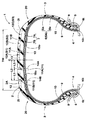
図1には、本実施形態の空気入りタイヤ1の正規状態における断面図が示される。ここで、正規状態とは、タイヤを正規リム(図示省略)にリム組みし、かつ、正規内圧を充填した無負荷の状態とし、以下特に言及しない場合、タイヤの各部の寸法等はこの正規状態で測定された値とする。
Hereinafter, an embodiment of the present invention will be described with reference to the drawings.
FIG. 1 shows a cross-sectional view of the pneumatic tire 1 of the present embodiment in a normal state. Here, the normal state is a state in which the tire is assembled to a normal rim (not shown) and filled with a normal internal pressure and is in a no-load state. Unless otherwise specified, the dimensions of each part of the tire are the normal state. The value measured at.
また前記「正規リム」とは、タイヤが基づいている規格を含む規格体系において、当該規格がタイヤ毎に定めるリムであり、例えばJATMAであれば "標準リム" 、TRAであれば "Design Rim" 、ETRTOであれば "Measuring Rim" とする。さらに「正規内圧」とは、タイヤが基づいている規格を含む規格体系において、各規格がタイヤ毎に定めている空気圧であり、JATMAであれば "最高空気圧" 、TRAであれば表 "TIRE LOAD LIMITS AT VARIOUS COLD INFLATION PRESSURES" に記載の最大値、ETRTOであれば "INFLATION PRESSURE" とするが、タイヤが乗用車用である場合には180kPaとする。 The “regular rim” is a rim determined for each tire in the standard system including the standard on which the tire is based. For example, “Standard Rim” for JATMA and “Design Rim” for TRA. For ETRTO, use "Measuring Rim". Furthermore, “regular internal pressure” is the air pressure that each standard defines for each tire in the standard system including the standard on which the tire is based. “JAMATA” is the “highest air pressure”, TRA is the table “TIRE LOAD” The maximum value described in “LIMITS AT VARIOUS COLD INFLATION PRESSURES”, “INFLATION PRESSURE” for ETRTO, but 180 kPa for tires for passenger cars.
本実施形態の空気入りタイヤ1は、トレッド部2からサイドウォール部3を経てビード部4のビードコア5に至るカーカス6と、このカーカス6のタイヤ半径方向外側かつトレッド部2の内部に配されたベルト層7と、前記カーカス6の内側に配されるインナーライナ9と、前記カーカス6とインナーライナ9との間に配されかつサイドウォール部3をタイヤ半径方向内外にのびる一対のタイゴム10、10とが設けられており、この例では乗用車用のラジアルタイヤが例示される。
The pneumatic tire 1 of the present embodiment is arranged in a
また、前記トレッド部2の外面2Aには、タイヤ周方向に連続してのびる溝幅が3mm以上の縦溝11と、この縦溝11を交わる向きにのびる横溝13とが、複数本形成されている。
The
前記縦溝11は、最もトレッド端2t側をタイヤ周方向に連続してのびる一対のショルダー縦溝11Bと、各ショルダー縦溝11Bにタイヤ軸方向内側で隣り合いかつタイヤ周方向に連続してのびる一対のミドル縦溝11Aとを含む。そして、トレッド部2の外面2Aには、一対のミドル縦溝11A、11Aによって区分されるクラウン陸部12A、ショルダー縦溝11Bとミドル縦溝11Aとによって区分されるミドル陸部12B、及びショルダー縦溝11Bよりも外側をなすショルダー陸部12Cが形成される。
The
本実施形態のクラウン陸部12Aには、横溝13によってタイヤ周方向に区分されたセンターブロックB1が複数形成される。また、ミドル陸部12B及びショルダー陸部12Cも同様に、横溝13によってタイヤ周方向に区分されたミドルブロックB2及びショルダーブロックB3がそれぞれ形成される。このように、各陸部12A、12B、12Cは、各ブロックB1、B2、B3がタイヤ周方向に並ぶブロック列として形成される。
In the
前記カーカス6は、カーカスコードをタイヤ赤道Cに対して例えば80゜〜90゜の角度で配列したラジアル構造の1枚以上、本例では1枚のカーカスプライ6Aにより構成されている。カーカスコードとしては、例えばポリエステル、ナイロン、レーヨン、アラミドなどの有機繊維コードや必要によりスチールコードが採用される。なお、本実施形態では、有機繊維コードが採用される。
The
またカーカスプライ6Aは、トレッド部2からサイドウォール部3を経てビード部4のビードコア5に至る本体部6aと、この本体部6aからのびて前記ビードコア5の廻りでタイヤ軸方向内側から外側に折り返された折返し部6bとを有する。
The
前記カーカスプライ6Aの本体部6aと折返し部6bとの間には、ビードコア5からタイヤ半径方向外側にのびかつ硬質ゴムからなるビードエーペックス8が配され、ビード部4が適宜補強される。
A
前記ベルト層7は、ベルトコードをタイヤ赤道Cに対して例えば10〜40°の小角度で傾けて配列した少なくとも2枚、本例ではタイヤ半径方向内、外2枚のベルトプライ7A、7Bを前記コードが互いに交差する向きに重ね合わせて構成される。ベルトコードは、本例ではスチールコードが採用されているが、アラミド、レーヨン等の高弾性の有機繊維コードも必要に応じて用いることができる。
The
前記インナーライナ9は、ゴムポリマー100質量部中に対して50質量部以上、好ましくは60質量部以上のブチル系ゴム、たとえば、ブチルゴム又はクロロブチルゴムやブロモブチルゴムなどのハロゲン化ブチルを含む空気非透過性に優れたゴム組成物からなり、タイヤ内腔面の空気漏れを防止する。
The
前記タイゴム10は、例えば、カーカスコード及び/又はトッピングゴムとの接着性に優れたゴム材から形成される。本実施形態のタイゴム10は、それぞれのタイヤ半径方向の内端10iが、カーカス6のタイヤ半径方向の内端6tまでのびるとともに、そのタイヤ半径方向の外端10oが、ミドル陸部12Bのタイヤ半径方向内方で終端する。本実施形態のタイゴム10は、タイヤ赤道Cに関して実質的に対称に配置されている。
The
本実施形態のタイゴム10としては、例えば、ゴムポリマー100質量部中に天然ゴムを例えば50質量部以上、好ましくは60質量部以上、より好ましくは65質量部以上を含む配合が好適に採用される。
As the
本実施形態のミドル陸部12Bは、バットレス領域20に比べて、その厚さが大きく形成されるとともに、ブロック列として形成される。このため、タイヤ製造工程中にタイゴム10の外端10oの位置がタイヤ軸方向に多少ばらついても、該ミドル陸部12Bの重量バランスに与える影響が比較的小さい。また、各タイゴム10のタイヤ半径方向の外端10oは、剛性が大きいベルト層7のタイヤ半径方向内方で終端することにもなる。よって、タイゴム10の位置のバラツキが、ミドル陸部12Bの剛性に与える影響も小さい。従って、本実施形態の空気入りタイヤ1は、タイゴム10を設けたことによるタイヤのユニフォミティの低下が抑制される。しかも、タイゴム10の外端10o間は、互いに離間させることができるので、その間の重量の増加を抑制しうる。
The
また、タイゴム10のタイヤ半径方向の外端10oは、ミドル縦溝11Aの溝中心線14A、とショルダー縦溝11Bの溝中心線14Bの中間位置から、タイヤ軸方向に、溝中心線14A、14B間の距離L1の±10%の領域で終端するのが好ましい。これにより、タイゴム10の外端10oは、厚さの小さい溝底から確実に離間させることができ、より一層タイヤのユニフォミティの低下が抑制される。
Further, the outer end 10o of the
なお、ショルダー縦溝11Bの溝中心線14Bは、例えば、タイヤ赤道Cからの距離L2がトレッド幅TWの20〜40%であるのが望ましく、またミドル縦溝11Aの溝中心線14Aは、タイヤ赤道Cからの距離L3がトレッド幅TWの5〜20%であることが好ましい。
The groove center line 14B of the shoulder
前記距離L2がトレッド幅TWの20%未満、又は前記距離L3がトレッド幅TWの5%未満であると、タイゴム10がタイヤ赤道C近傍まで配されるため、タイヤ重量が増加するおそれがある。逆に、距離L2がトレッド幅TWの40%を超える場合、又は、距離L3がトレッド幅TWの20%を超える場合、タイゴム10の外端10oが、比較的厚さの小さなバットレス領域20に近づくため、タイヤのユニフォミティが低下するおそれがある。
If the distance L2 is less than 20% of the tread width TW, or the distance L3 is less than 5% of the tread width TW, the
以上のような観点により、前記距離L2は、トレッド幅TWの好ましくは20%以上、さらに好ましくは25%以上が望ましく、また、トレッド幅TWの好ましくは40%以下、さらに好ましくは35%以下が望ましい。また、距離L3は、トレッド幅TWの好ましくは5%以上、さらに好ましくは10%以上が望ましく、また、トレッド幅TWの好ましくは20%以下、さらに好ましくは15%以下が望ましい。 From the above viewpoint, the distance L2 is preferably 20% or more of the tread width TW, more preferably 25% or more, and preferably 40% or less, more preferably 35% or less of the tread width TW. desirable. The distance L3 is preferably 5% or more of the tread width TW, more preferably 10% or more, and preferably 20% or less, more preferably 15% or less of the tread width TW.
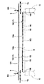
図2には、本実施形態の空気入りタイヤ1の製造工程の一例を示す。本実施形態のタイゴム10は、リボン状の未加硫のゴムストリップ16をタイヤ周方向へ螺旋状に巻き付けることによりシート状に形成されたストリップ積層体17からなる。このようなタイゴム10は、その厚さ及び長さが、タイヤサイズ等に応じて自在に形成できる点で望ましい。
In FIG. 2, an example of the manufacturing process of the pneumatic tire 1 of this embodiment is shown. The
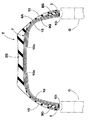
図2に示す工程では、円筒状の成形ドラムDの上に巻回された未加硫のインナーライナゴム9Gの上に、ゴムストリップ16が、例えば外端10oから内端10iに向かって螺旋状に巻回されて、タイゴム10が形成される。この外端10oの位置は、予めミドル陸部の内方となる既知の位置である。そして、インナーライナゴム9G及びタイゴム10の外側に、サイドウォールゴム15及びカーカスプライ6Aが順次巻回され、その両側から、ビードエーペックスゴム8Gを取付けたビードコア5が軸方向外側から嵌め込まれる。以後は常法に従って、図3のような生タイヤTが成形され、かつ図1のように加硫される。このような製造工程により、本実施形態の空気入りタイヤ1が製造される。
In the process shown in FIG. 2, the
以上、本発明の特に好ましい実施形態について詳述したが、本発明は図示の実施形態に限定されることなく、種々の態様に変形して実施しうる。 As mentioned above, although especially preferable embodiment of this invention was explained in full detail, this invention is not limited to embodiment of illustration, It can deform | transform and implement in a various aspect.
タイヤサイズが245/45R19の乗用車用空気入りタイヤを、表1の仕様に基づいて試作するとともに、各タイヤをリム組みし(リムサイズ19×8.0J、内圧200kPa)、それらの性能を比較した。また、表2には、インナーライナ、タイゴム及びカーカスプライのトッピングゴムの配合を示す。テスト方法は次のとおりである。 A pneumatic tire for a passenger car having a tire size of 245 / 45R19 was prototyped based on the specifications shown in Table 1, and each tire was assembled with a rim (rim size 19 × 8.0 J, internal pressure 200 kPa), and their performance was compared. Table 2 shows the composition of the inner liner, tie rubber, and carcass ply topping rubber. The test method is as follows.
<タイヤのユニフォミティ>
各テストタイヤについて、JASO C607:2000のユニフォミティ試験条件に準拠して、回転時のタイヤ半径方向の力の変動成分であるラジアルフォースバリエーション(RFV)及び回転時の前後方向の力の変動成分であるタンジェンシャルフォースバリエーション(TFV)がそれぞれ測定された。RFVについては、高速回転時(120km/H)の1次の値が計測された。TFVについては、高速回転時の1次及び2次が測定された。結果は、各テストタイヤ5本の平均値を求め、比較例1の各平均値を100とする指数で表示した。数値が小さいほどユニフォミティに優れていることを示す。
テストの結果を表1に示す。
<Tire uniformity>
For each test tire, in accordance with JASO C607: 2000 uniformity test conditions, radial force variation (RFV) which is a fluctuation component of force in the tire radial direction during rotation and a fluctuation component of force in the front-rear direction during rotation Tangential force variation (TFV) was measured respectively. For RFV, the primary value at high speed rotation (120 km / H) was measured. For TFV, the primary and secondary during high speed rotation were measured. The result was obtained by calculating an average value of five test tires and displaying the average value of Comparative Example 1 as 100. The smaller the value, the better the uniformity.
The test results are shown in Table 1.
<タイヤ重量>
タイヤ1本当たりの重量を測定し、比較例1を100とする指数で表示している。指数は小さい方が良好である。
<Tire weight>
The weight per tire was measured and displayed as an index with Comparative Example 1 taken as 100. A smaller index is better.
テストの結果を表1に示す。 The test results are shown in Table 1.
テストの結果、実施例の空気入りタイヤは、重量の増加を抑制しつつ、ユニフォミティの低下を抑制できることが確認できた。 As a result of the test, it was confirmed that the pneumatic tire of the example can suppress a decrease in uniformity while suppressing an increase in weight.
1 空気入りタイヤ
2 トレッド部
2A 外面
2t トレッド端
3 サイドウォール部
4 ビード部
5 ビードコア
6 カーカス
7 ベルト層
8 ビードエーペックス
9 インナーライナ
10 タイゴム
11A ミドル縦溝
11B ショルダー縦溝
12B ミドル陸部
DESCRIPTION OF SYMBOLS 1 Pneumatic tire 2
Claims (3)
前記トレッド部の外面には、最もトレッド端側をタイヤ周方向に連続してのびる一対のショルダー縦溝と、各ショルダー縦溝にタイヤ軸方向内側で隣り合いかつタイヤ周方向に連続してのびる一対のミドル縦溝とが形成されるとともに、
前記ショルダー縦溝と前記ミドル縦溝との間のミドル陸部は、ミドルブロックがタイヤ周方向に並ぶブロック列であり、
前記各タイゴムのタイヤ半径方向の外端は、前記ミドル陸部のタイヤ半径方向内方、かつ、前記ミドル縦溝の溝中心線と前記ショルダー縦溝の溝中心線の中間位置から、タイヤ軸方向に、前記溝中心線間の距離L1の±10%の領域で終端することを特徴とする空気入りタイヤ。 A carcass extending from the tread portion through the sidewall portion to the bead core of the bead portion, a belt layer disposed outside the carcass in the tire radial direction and inside the tread portion, and an inner liner disposed inside the carcass And a pneumatic tire having a pair of tie rubbers disposed between the carcass and the inner liner and extending a sidewall portion inward and outward in the tire radial direction,
On the outer surface of the tread portion, a pair of shoulder vertical grooves extending continuously in the tire circumferential direction on the most tread end side, and a pair extending adjacent to each shoulder vertical groove in the tire axial direction and continuously extending in the tire circumferential direction With the middle vertical groove of
The middle land portion between the shoulder longitudinal groove and the middle longitudinal groove is a block row in which middle blocks are arranged in the tire circumferential direction,
The outer end of each tie rubber in the tire radial direction is inward of the tire in the tire radial direction of the middle land portion , and from the middle position between the groove center line of the middle vertical groove and the groove center line of the shoulder vertical groove, in the tire axial direction. Further, the pneumatic tire terminates in a region of ± 10% of the distance L1 between the groove center lines .
3. The pneumatic tire according to claim 1, wherein the tie rubber is formed of a strip laminated body formed in a sheet shape by spirally winding a ribbon-shaped unvulcanized rubber strip in the tire circumferential direction .
Priority Applications (1)
| Application Number | Priority Date | Filing Date | Title |
|---|---|---|---|
| JP2009115721A JP5723086B2 (en) | 2009-05-12 | 2009-05-12 | Pneumatic tire |
Applications Claiming Priority (1)
| Application Number | Priority Date | Filing Date | Title |
|---|---|---|---|
| JP2009115721A JP5723086B2 (en) | 2009-05-12 | 2009-05-12 | Pneumatic tire |
Publications (2)
| Publication Number | Publication Date |
|---|---|
| JP2010264792A JP2010264792A (en) | 2010-11-25 |
| JP5723086B2 true JP5723086B2 (en) | 2015-05-27 |
Family
ID=43362199
Family Applications (1)
| Application Number | Title | Priority Date | Filing Date |
|---|---|---|---|
| JP2009115721A Active JP5723086B2 (en) | 2009-05-12 | 2009-05-12 | Pneumatic tire |
Country Status (1)
| Country | Link |
|---|---|
| JP (1) | JP5723086B2 (en) |
Cited By (2)
| Publication number | Priority date | Publication date | Assignee | Title |
|---|---|---|---|---|
| JP2017149214A (en) * | 2016-02-23 | 2017-08-31 | 横浜ゴム株式会社 | Pneumatic tire |
| JP2017165135A (en) * | 2016-03-14 | 2017-09-21 | 横浜ゴム株式会社 | Method for production of pneumatic tire |
Families Citing this family (5)
| Publication number | Priority date | Publication date | Assignee | Title |
|---|---|---|---|---|
| JP2012166712A (en) * | 2011-02-15 | 2012-09-06 | Sumitomo Rubber Ind Ltd | Pneumatic radial tire |
| JP6306975B2 (en) * | 2014-08-12 | 2018-04-04 | 住友ゴム工業株式会社 | Pneumatic tire manufacturing method |
| JP6376210B2 (en) * | 2016-11-22 | 2018-08-22 | 横浜ゴム株式会社 | Pneumatic tire |
| JP6424919B2 (en) * | 2017-04-19 | 2018-11-21 | 横浜ゴム株式会社 | Pneumatic tire and method of manufacturing the same |
| JP2022038812A (en) * | 2020-08-27 | 2022-03-10 | 住友ゴム工業株式会社 | tire |
Family Cites Families (5)
| Publication number | Priority date | Publication date | Assignee | Title |
|---|---|---|---|---|
| JP3372340B2 (en) * | 1994-02-22 | 2003-02-04 | 住友ゴム工業株式会社 | Pneumatic tire |
| JP3774116B2 (en) * | 2000-11-28 | 2006-05-10 | 住友ゴム工業株式会社 | Pneumatic tire |
| JP2002178714A (en) * | 2000-12-08 | 2002-06-26 | Sumitomo Rubber Ind Ltd | Pneumatic tire |
| JP2004276759A (en) * | 2003-03-17 | 2004-10-07 | Yokohama Rubber Co Ltd:The | Pneumatic tire |
| JP4262286B1 (en) * | 2007-10-23 | 2009-05-13 | 住友ゴム工業株式会社 | Pneumatic tire |
-
2009
- 2009-05-12 JP JP2009115721A patent/JP5723086B2/en active Active
Cited By (6)
| Publication number | Priority date | Publication date | Assignee | Title |
|---|---|---|---|---|
| JP2017149214A (en) * | 2016-02-23 | 2017-08-31 | 横浜ゴム株式会社 | Pneumatic tire |
| US11498363B2 (en) | 2016-02-23 | 2022-11-15 | The Yokohama Rubber Co., Ltd. | Pneumatic tire |
| JP2017165135A (en) * | 2016-03-14 | 2017-09-21 | 横浜ゴム株式会社 | Method for production of pneumatic tire |
| CN108778779A (en) * | 2016-03-14 | 2018-11-09 | 横滨橡胶株式会社 | Pneumatic tire and its manufacturing method |
| CN108778779B (en) * | 2016-03-14 | 2020-10-13 | 横滨橡胶株式会社 | Pneumatic tire and method for manufacturing same |
| US11453187B2 (en) | 2016-03-14 | 2022-09-27 | The Yokohama Rubber Co., Ltd. | Pneumatic tire and method for manufacturing same |
Also Published As
| Publication number | Publication date |
|---|---|
| JP2010264792A (en) | 2010-11-25 |
Similar Documents
| Publication | Publication Date | Title |
|---|---|---|
| KR101972175B1 (en) | Run flat tire | |
| US10434823B2 (en) | Pneumatic radial tire for a passenger vehicle and method of using the same | |
| US9272578B2 (en) | Pneumatic tire | |
| JP5723086B2 (en) | Pneumatic tire | |
| JP5986513B2 (en) | Heavy duty tire | |
| US20150165822A1 (en) | Pneumatic Tire | |
| WO2020066906A1 (en) | Pneumatic tire | |
| JP4933824B2 (en) | Run-flat tire and manufacturing method thereof | |
| JP6059429B2 (en) | Pneumatic tire | |
| JP5816214B2 (en) | Pneumatic tire | |
| JP5357933B2 (en) | Pneumatic tire | |
| WO2013047192A1 (en) | Run-flat tire | |
| JP2013035348A (en) | Pneumatic tire | |
| JP5559235B2 (en) | Pneumatic tire | |
| JP4944487B2 (en) | Run-flat tire and manufacturing method thereof | |
| JP7200680B2 (en) | pneumatic tire | |
| US20140290821A1 (en) | Run flat tire | |
| JP2018111356A (en) | Pneumatic tire | |
| JP7031397B2 (en) | Run flat tire | |
| JP5654868B2 (en) | Pneumatic tire | |
| JP2012040780A (en) | Method of manufacturing pneumatic tire, and pneumatic tire | |
| WO2019111876A1 (en) | Pneumatic tire | |
| JP3771545B2 (en) | Pneumatic tire | |
| JP6455095B2 (en) | Pneumatic tire | |
| JP4486408B2 (en) | Pneumatic tire |
Legal Events
| Date | Code | Title | Description |
|---|---|---|---|
| A621 | Written request for application examination |
Free format text: JAPANESE INTERMEDIATE CODE: A621 Effective date: 20120328 |
|
| A977 | Report on retrieval |
Free format text: JAPANESE INTERMEDIATE CODE: A971007 Effective date: 20130517 |
|
| A131 | Notification of reasons for refusal |
Free format text: JAPANESE INTERMEDIATE CODE: A131 Effective date: 20130521 |
|
| A02 | Decision of refusal |
Free format text: JAPANESE INTERMEDIATE CODE: A02 Effective date: 20131119 |
|
| A521 | Request for written amendment filed |
Free format text: JAPANESE INTERMEDIATE CODE: A523 Effective date: 20150123 |
|
| A61 | First payment of annual fees (during grant procedure) |
Free format text: JAPANESE INTERMEDIATE CODE: A61 Effective date: 20150327 |
|
| R150 | Certificate of patent or registration of utility model |
Ref document number: 5723086 Country of ref document: JP Free format text: JAPANESE INTERMEDIATE CODE: R150 |
|
| R250 | Receipt of annual fees |
Free format text: JAPANESE INTERMEDIATE CODE: R250 |
|
| R250 | Receipt of annual fees |
Free format text: JAPANESE INTERMEDIATE CODE: R250 |
|
| R250 | Receipt of annual fees |
Free format text: JAPANESE INTERMEDIATE CODE: R250 |
|
| R250 | Receipt of annual fees |
Free format text: JAPANESE INTERMEDIATE CODE: R250 |
|
| R250 | Receipt of annual fees |
Free format text: JAPANESE INTERMEDIATE CODE: R250 |
|
| R250 | Receipt of annual fees |
Free format text: JAPANESE INTERMEDIATE CODE: R250 |
|
| R250 | Receipt of annual fees |
Free format text: JAPANESE INTERMEDIATE CODE: R250 |