JP2017164242A - Game machine - Google Patents
Game machine Download PDFInfo
- Publication number
- JP2017164242A JP2017164242A JP2016051722A JP2016051722A JP2017164242A JP 2017164242 A JP2017164242 A JP 2017164242A JP 2016051722 A JP2016051722 A JP 2016051722A JP 2016051722 A JP2016051722 A JP 2016051722A JP 2017164242 A JP2017164242 A JP 2017164242A
- Authority
- JP
- Japan
- Prior art keywords
- displacement member
- game
- state
- display
- privilege
- Prior art date
- Legal status (The legal status is an assumption and is not a legal conclusion. Google has not performed a legal analysis and makes no representation as to the accuracy of the status listed.)
- Pending
Links
- 230000000694 effects Effects 0.000 claims description 727
- 230000001976 improved effect Effects 0.000 abstract description 26
- 238000000034 method Methods 0.000 description 1617
- 230000008569 process Effects 0.000 description 1591
- 238000006073 displacement reaction Methods 0.000 description 1493
- 238000012546 transfer Methods 0.000 description 394
- 230000000875 corresponding effect Effects 0.000 description 381
- 238000012545 processing Methods 0.000 description 351
- 239000000872 buffer Substances 0.000 description 304
- 230000008859 change Effects 0.000 description 294
- 238000003860 storage Methods 0.000 description 224
- 238000010586 diagram Methods 0.000 description 216
- 230000005540 biological transmission Effects 0.000 description 205
- 230000002730 additional effect Effects 0.000 description 166
- 230000015654 memory Effects 0.000 description 114
- 238000004519 manufacturing process Methods 0.000 description 112
- 230000002829 reductive effect Effects 0.000 description 78
- 230000001965 increasing effect Effects 0.000 description 66
- 230000007704 transition Effects 0.000 description 61
- 230000009471 action Effects 0.000 description 51
- 230000007246 mechanism Effects 0.000 description 49
- 230000036544 posture Effects 0.000 description 46
- 230000009467 reduction Effects 0.000 description 41
- 238000005034 decoration Methods 0.000 description 39
- 230000033001 locomotion Effects 0.000 description 36
- 230000036961 partial effect Effects 0.000 description 32
- 230000002093 peripheral effect Effects 0.000 description 31
- 238000005096 rolling process Methods 0.000 description 31
- 230000004048 modification Effects 0.000 description 29
- 238000012986 modification Methods 0.000 description 29
- 238000001514 detection method Methods 0.000 description 27
- 230000005484 gravity Effects 0.000 description 26
- 238000012790 confirmation Methods 0.000 description 25
- 238000005259 measurement Methods 0.000 description 23
- 239000000758 substrate Substances 0.000 description 22
- 238000007792 addition Methods 0.000 description 21
- 230000002441 reversible effect Effects 0.000 description 21
- 230000006378 damage Effects 0.000 description 20
- 238000001125 extrusion Methods 0.000 description 17
- 238000003780 insertion Methods 0.000 description 17
- 230000037431 insertion Effects 0.000 description 17
- 238000011084 recovery Methods 0.000 description 17
- 238000012544 monitoring process Methods 0.000 description 16
- 239000000463 material Substances 0.000 description 15
- 238000013459 approach Methods 0.000 description 14
- 238000005452 bending Methods 0.000 description 14
- 238000005192 partition Methods 0.000 description 14
- 238000009826 distribution Methods 0.000 description 13
- 238000010304 firing Methods 0.000 description 13
- 210000000078 claw Anatomy 0.000 description 11
- 230000006870 function Effects 0.000 description 11
- 238000003825 pressing Methods 0.000 description 11
- 239000011347 resin Substances 0.000 description 11
- 229920005989 resin Polymers 0.000 description 11
- 230000004044 response Effects 0.000 description 11
- 230000000007 visual effect Effects 0.000 description 11
- 230000015572 biosynthetic process Effects 0.000 description 10
- 230000003247 decreasing effect Effects 0.000 description 9
- 230000001105 regulatory effect Effects 0.000 description 9
- 238000009877 rendering Methods 0.000 description 9
- 230000000717 retained effect Effects 0.000 description 9
- 230000001788 irregular Effects 0.000 description 8
- 238000002156 mixing Methods 0.000 description 8
- 230000008093 supporting effect Effects 0.000 description 8
- 241000283973 Oryctolagus cuniculus Species 0.000 description 7
- 230000005856 abnormality Effects 0.000 description 7
- 230000008901 benefit Effects 0.000 description 7
- 230000001276 controlling effect Effects 0.000 description 7
- 230000008878 coupling Effects 0.000 description 6
- 238000010168 coupling process Methods 0.000 description 6
- 238000005859 coupling reaction Methods 0.000 description 6
- 238000007654 immersion Methods 0.000 description 6
- 239000007788 liquid Substances 0.000 description 6
- 239000002184 metal Substances 0.000 description 6
- 229910052751 metal Inorganic materials 0.000 description 6
- 230000008450 motivation Effects 0.000 description 6
- 238000011144 upstream manufacturing Methods 0.000 description 6
- 230000002950 deficient Effects 0.000 description 5
- 230000003111 delayed effect Effects 0.000 description 5
- 239000000284 extract Substances 0.000 description 5
- 230000001771 impaired effect Effects 0.000 description 5
- 230000002452 interceptive effect Effects 0.000 description 5
- 239000004973 liquid crystal related substance Substances 0.000 description 5
- 230000004323 axial length Effects 0.000 description 4
- 238000012937 correction Methods 0.000 description 4
- 230000001186 cumulative effect Effects 0.000 description 4
- 230000007547 defect Effects 0.000 description 4
- 238000013461 design Methods 0.000 description 4
- 238000007599 discharging Methods 0.000 description 4
- 230000007774 longterm Effects 0.000 description 4
- 230000001360 synchronised effect Effects 0.000 description 4
- 238000010276 construction Methods 0.000 description 3
- 230000003028 elevating effect Effects 0.000 description 3
- 239000011521 glass Substances 0.000 description 3
- 230000009191 jumping Effects 0.000 description 3
- 238000007726 management method Methods 0.000 description 3
- 238000000465 moulding Methods 0.000 description 3
- 230000004043 responsiveness Effects 0.000 description 3
- 238000007789 sealing Methods 0.000 description 3
- 238000004904 shortening Methods 0.000 description 3
- XEEYBQQBJWHFJM-UHFFFAOYSA-N Iron Chemical compound [Fe] XEEYBQQBJWHFJM-UHFFFAOYSA-N 0.000 description 2
- 241001465754 Metazoa Species 0.000 description 2
- 230000003321 amplification Effects 0.000 description 2
- 230000001174 ascending effect Effects 0.000 description 2
- 230000008602 contraction Effects 0.000 description 2
- 238000000354 decomposition reaction Methods 0.000 description 2
- 230000007423 decrease Effects 0.000 description 2
- 230000006866 deterioration Effects 0.000 description 2
- 230000002708 enhancing effect Effects 0.000 description 2
- 238000005286 illumination Methods 0.000 description 2
- 230000006872 improvement Effects 0.000 description 2
- 230000007257 malfunction Effects 0.000 description 2
- 230000013011 mating Effects 0.000 description 2
- 238000003199 nucleic acid amplification method Methods 0.000 description 2
- 238000002360 preparation method Methods 0.000 description 2
- 238000010079 rubber tapping Methods 0.000 description 2
- 230000007480 spreading Effects 0.000 description 2
- 238000003892 spreading Methods 0.000 description 2
- QNRATNLHPGXHMA-XZHTYLCXSA-N (r)-(6-ethoxyquinolin-4-yl)-[(2s,4s,5r)-5-ethyl-1-azabicyclo[2.2.2]octan-2-yl]methanol;hydrochloride Chemical compound Cl.C([C@H]([C@H](C1)CC)C2)CN1[C@@H]2[C@H](O)C1=CC=NC2=CC=C(OCC)C=C21 QNRATNLHPGXHMA-XZHTYLCXSA-N 0.000 description 1
- KRQUFUKTQHISJB-YYADALCUSA-N 2-[(E)-N-[2-(4-chlorophenoxy)propoxy]-C-propylcarbonimidoyl]-3-hydroxy-5-(thian-3-yl)cyclohex-2-en-1-one Chemical compound CCC\C(=N/OCC(C)OC1=CC=C(Cl)C=C1)C1=C(O)CC(CC1=O)C1CCCSC1 KRQUFUKTQHISJB-YYADALCUSA-N 0.000 description 1
- 229910001369 Brass Inorganic materials 0.000 description 1
- 241000274965 Cyrestis thyodamas Species 0.000 description 1
- 241000196324 Embryophyta Species 0.000 description 1
- JOYRKODLDBILNP-UHFFFAOYSA-N Ethyl urethane Chemical compound CCOC(N)=O JOYRKODLDBILNP-UHFFFAOYSA-N 0.000 description 1
- 241000406668 Loxodonta cyclotis Species 0.000 description 1
- 241000282320 Panthera leo Species 0.000 description 1
- 206010044565 Tremor Diseases 0.000 description 1
- 241001314440 Triphora trianthophoros Species 0.000 description 1
- 230000004308 accommodation Effects 0.000 description 1
- 238000009825 accumulation Methods 0.000 description 1
- 229920000122 acrylonitrile butadiene styrene Polymers 0.000 description 1
- 230000003213 activating effect Effects 0.000 description 1
- 230000002238 attenuated effect Effects 0.000 description 1
- 230000006399 behavior Effects 0.000 description 1
- OMFRMAHOUUJSGP-IRHGGOMRSA-N bifenthrin Chemical compound C1=CC=C(C=2C=CC=CC=2)C(C)=C1COC(=O)[C@@H]1[C@H](\C=C(/Cl)C(F)(F)F)C1(C)C OMFRMAHOUUJSGP-IRHGGOMRSA-N 0.000 description 1
- 230000033228 biological regulation Effects 0.000 description 1
- 230000004397 blinking Effects 0.000 description 1
- 239000010951 brass Substances 0.000 description 1
- 238000006243 chemical reaction Methods 0.000 description 1
- 239000003086 colorant Substances 0.000 description 1
- 239000012141 concentrate Substances 0.000 description 1
- 238000012217 deletion Methods 0.000 description 1
- 230000037430 deletion Effects 0.000 description 1
- 230000005489 elastic deformation Effects 0.000 description 1
- 230000001747 exhibiting effect Effects 0.000 description 1
- 238000000605 extraction Methods 0.000 description 1
- 230000004438 eyesight Effects 0.000 description 1
- 238000001914 filtration Methods 0.000 description 1
- 239000005357 flat glass Substances 0.000 description 1
- 230000003760 hair shine Effects 0.000 description 1
- 238000009434 installation Methods 0.000 description 1
- 229910052742 iron Inorganic materials 0.000 description 1
- 238000012423 maintenance Methods 0.000 description 1
- 230000014759 maintenance of location Effects 0.000 description 1
- 239000007769 metal material Substances 0.000 description 1
- 239000000203 mixture Substances 0.000 description 1
- 230000001151 other effect Effects 0.000 description 1
- 230000000149 penetrating effect Effects 0.000 description 1
- 230000000737 periodic effect Effects 0.000 description 1
- 230000010363 phase shift Effects 0.000 description 1
- 238000004886 process control Methods 0.000 description 1
- 230000001681 protective effect Effects 0.000 description 1
- 230000008707 rearrangement Effects 0.000 description 1
- 230000008439 repair process Effects 0.000 description 1
- 230000000630 rising effect Effects 0.000 description 1
- 239000011435 rock Substances 0.000 description 1
- 238000009751 slip forming Methods 0.000 description 1
- 239000000126 substance Substances 0.000 description 1
- 230000002195 synergetic effect Effects 0.000 description 1
- 238000003786 synthesis reaction Methods 0.000 description 1
- 238000002834 transmittance Methods 0.000 description 1
- 230000001960 triggered effect Effects 0.000 description 1
- 239000002023 wood Substances 0.000 description 1
Images


Abstract
Description
本発明は、パチンコ機などの遊技機に関するものである。 The present invention relates to a gaming machine such as a pachinko machine.
パチンコ機等の遊技機には、始動入賞口への遊技球の入賞に基づいて行われる抽選の結果が当たりだった場合に、当たり状態へと移行するものがある。かかる遊技機の中には、当たり状態の終了を契機として、当たり状態が通常の確率で抽選される通常状態と、当たり状態が通常状態よりも高い確率で抽選される確率変動状態とのいずれかに設定されるものがある。 Some gaming machines such as pachinko machines shift to a winning state when the result of a lottery performed based on the winning of a game ball at the start winning opening is a win. Among such gaming machines, one of a normal state in which the winning state is drawn with a normal probability and a probability fluctuation state in which the winning state is drawn with a higher probability than the normal state, triggered by the end of the winning state Some are set to.
しかしながら、更に興趣の向上することができる遊技機が求められていた。 However, there is a need for a gaming machine that can further enhance interest.
本発明は、上記例示した問題点等を解決するためになされたものであり、遊技者の遊技に対する興趣を向上させることができる遊技機を提供することを目的とする。 The present invention has been made in order to solve the above-described problems and the like, and an object thereof is to provide a gaming machine that can improve the interest of a player in games.
この目的を達成するために請求項1記載の遊技機は、判別条件の成立に基づいて判別を実行する判別手段と、その判別手段による判別で特定の判別結果となったことに基づいて、異なる複数の特典遊技のうち、1の特典遊技を実行する特典遊技実行手段と、その特典遊技実行手段により実行される前記特典遊技の種別を設定する特典種別設定手段と、を有し、前記特典種別設定手段は、前記判別手段の判別結果に基づいて、少なくとも遊技者に所定の特典を付与する第1特典種別、または、その第1特典種別よりも遊技者に有利となる特定の特典を付与する第2特典種別のうち何れかを設定するものであり、前記判別手段による判別の結果に基づく情報を前記特典種別設定手段により設定される前記特典種別を識別困難に表示する表示手段と、を備えている。
In order to achieve this object, the gaming machine according to
請求項2記載の遊技機は、請求項1記載の遊技機において、前記特典遊技実行手段により前記特典遊技が実行された場合に、遊技球が入球困難な第1状態からその第1状態よりも入球し易い第2状態へと所定条件が成立するまで可変する可変入球手段と、その可変入球手段に遊技球が入球したことに基づいて実行条件の成立を判別する条件判別手段と、その条件判別手段により実行条件が成立したと判別された場合に演出を実行可能な演出実行手段と、前記特典遊技実行手段により実行される前記特典遊技の種別に基づいて、前記実行条件が成立する割合を可変して設定する割合可変手段と、を有するものである。
The gaming machine according to
請求項3記載の遊技機は、請求項2記載の遊技機において、前記可変入球手段に遊技球が入球したことに基づいて、予め定められた所定数の遊技球を賞球として遊技者に払い出す払出手段を有し、前記演出は、前記払出手段により払い出される前記賞球の数に基づいて設定されるものである。
The gaming machine according to
請求項4記載の遊技機は、請求項2または3記載の遊技機において、前記特典遊技実行手段は、前記可変入球手段に遊技球が入球し易い第1特典遊技と、その第1特典遊技よりも遊技球の入球が困難となる第2特典遊技と、を少なくとも実行可能であり、前記割合可変手段は、前記第1特典遊技が実行される場合には、前記第2特典遊技が実行される場合よりも前記割合を低く設定するものである。 According to a fourth aspect of the present invention, in the gaming machine according to the second or third aspect, the privilege game execution means includes a first privilege game in which a game ball can easily enter the variable entry means, and the first privilege. At least a second bonus game that makes it difficult to enter a game ball than a game, and when the first bonus game is executed, the ratio variable means can execute the second bonus game. The said ratio is set lower than the case where it is performed.
請求項5記載の遊技機は、請求項2から4のいずれかに記載の遊技機において、前記演出は、演出態様の少なくとも一つとして表示態様を表示手段に表示するものである。 A gaming machine according to a fifth aspect is the gaming machine according to any one of the second to fourth aspects, wherein the effect is displayed on the display means as at least one of the effect modes.
請求項1記載の遊技機によれば、判別条件の成立に基づいて判別を実行する判別手段と、その判別手段による判別で特定の判別結果となったことに基づいて、異なる複数の特典遊技のうち、1の特典遊技を実行する特典遊技実行手段と、その特典遊技実行手段により実行される前記特典遊技の種別を設定する特典種別設定手段と、を有し、前記特典種別設定手段は、前記判別手段の判別結果に基づいて、少なくとも遊技者に所定の特典を付与する第1特典種別、または、その第1特典種別よりも遊技者に有利となる特定の特典を付与する第2特典種別のうち何れかを設定するものであり、前記判別手段による判別の結果に基づく情報を前記特典種別設定手段により設定される前記特典種別を識別困難に表示する表示手段と、を備えている。 According to the gaming machine of the first aspect, the discriminating means for executing discrimination based on the establishment of the discriminating condition, and a plurality of different privilege games based on the fact that the discrimination by the discriminating means results in a specific discrimination result Among them, it has a privilege game executing means for executing one privilege game, and a privilege type setting means for setting the type of the privilege game executed by the privilege game executing means, Based on the determination result of the determining means, at least a first privilege type that gives a predetermined privilege to the player, or a second privilege type that gives a specific privilege that is more advantageous to the player than the first privilege type. Any one of which is set, and includes display means for displaying information based on the result of determination by the determination means so as to make it difficult to identify the privilege type set by the privilege type setting means.
これにより、遊技の興趣を向上できるという効果がある。 Thereby, there is an effect that the interest of the game can be improved.
請求項2記載の遊技機によれば、請求項1記載の遊技機の奏する効果に加え、次の効果を奏する。即ち、特典遊技実行手段により前記特典遊技が実行された場合に、遊技球が入球困難な第1状態からその第1状態よりも入球し易い第2状態へと所定条件が成立するまで可変する可変入球手段と、その可変入球手段に遊技球が入球したことに基づいて実行条件の成立を判別する条件判別手段と、その条件判別手段により実行条件が成立したと判別された場合に演出を実行可能な演出実行手段と、前記特典遊技実行手段により実行される前記特典遊技の種別に基づいて、前記実行条件が成立する割合を可変して設定する割合可変手段と、を有するものである。 According to the gaming machine of the second aspect, in addition to the effect of the gaming machine of the first aspect, the following effect can be obtained. That is, when the privilege game is executed by the privilege game execution means, the game ball is variable from the first state in which the game ball is difficult to enter to the second state in which the game ball is easier to enter than the first state until a predetermined condition is satisfied. A variable entry means that determines whether the execution condition is satisfied based on the fact that a game ball has entered the variable entry means, and the condition determination means determines that the execution condition is satisfied. Production execution means capable of executing the production, and ratio variable means for variably setting the ratio at which the execution condition is established based on the type of the bonus game executed by the bonus game execution means. It is.
これにより、遊技の興趣を向上できるという効果がある。 Thereby, there is an effect that the interest of the game can be improved.
請求項3記載の遊技機によれば、請求項2記載の遊技機の奏する効果に加え、次の効果を奏する。即ち、前記可変入球手段に遊技球が入球したことに基づいて、予め定められた所定数の遊技球を賞球として遊技者に払い出す払出手段を有し、前記演出は、前記払出手段により払い出される前記賞球の数に基づいて設定されるものである。 According to the gaming machine of the third aspect, in addition to the effect produced by the gaming machine according to the second aspect, the following effect is produced. That is, it has payout means for paying a player a predetermined number of game balls as prize balls based on the fact that a game ball has entered the variable ball entry means, and the effect is the payout means Is set based on the number of prize balls to be paid out.
これにより、遊技の興趣を向上できるという効果がある。 Thereby, there is an effect that the interest of the game can be improved.
請求項4記載の遊技機によれば、請求項2または3記載の遊技機の奏する効果に加え、次の効果を奏する。即ち、前記特典遊技実行手段は、前記可変入球手段に遊技球が入球し易い第1特典遊技と、その第1特典遊技よりも遊技球の入球が困難となる第2特典遊技と、を少なくとも実行可能であり、前記割合可変手段は、前記第1特典遊技が実行される場合には、前記第2特典遊技が実行される場合よりも前記割合を低く設定するものである。 According to the gaming machine of the fourth aspect, in addition to the effect produced by the gaming machine of the second or third aspect, the following effect is produced. That is, the privilege game execution means includes a first privilege game in which a game ball can easily enter the variable entry means, a second privilege game in which entry of the game ball is more difficult than the first privilege game, The ratio variable means sets the ratio lower when the first privilege game is executed than when the second privilege game is executed.
これにより、遊技の興趣を向上できるという効果がある。 Thereby, there is an effect that the interest of the game can be improved.
請求項5記載の遊技機によれば、請求項2から4のいずれかに記載の遊技機の奏する効果に加え、次の効果を奏する。即ち、前記演出は、演出態様の少なくとも一つとして表示態様を表示手段に表示するものである。 According to the gaming machine of the fifth aspect, in addition to the effect produced by the gaming machine according to any one of the second to fourth aspects, the following effect is achieved. That is, the effect is to display the display mode on the display means as at least one of the effect modes.
これにより、遊技の興趣を向上できるという効果がある。 Thereby, there is an effect that the interest of the game can be improved.
<第1実施形態>
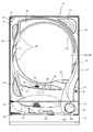
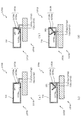
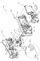
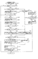
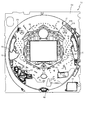
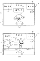
以下、本発明の実施形態について、添付図面を参照して説明する。まず、図1から図60を参照し、第1実施形態として、本発明をパチンコ遊技機(以下、単に「パチンコ機」という)10に適用した場合の一実施形態について説明する。図1は、第1実施形態におけるパチンコ機10の正面図であり、図2はパチンコ機10の遊技盤13の正面図であり、図3はパチンコ機10の背面図である。
<First Embodiment>
Embodiments of the present invention will be described below with reference to the accompanying drawings. First, with reference to FIG. 1 to FIG. 60, an embodiment in which the present invention is applied to a pachinko gaming machine (hereinafter simply referred to as “pachinko machine”) 10 will be described as a first embodiment. 1 is a front view of a
図1に示すように、パチンコ機10は、略矩形状に組み合わせた木枠により外殻が形成される外枠11と、その外枠11と略同一の外形形状に形成され外枠11に対して開閉可能に支持された内枠12とを備えている。外枠11には、内枠12を支持するために正面視(図1参照)左側の上下2カ所に金属製のヒンジ18が取り付けられ、そのヒンジ18が設けられた側を開閉の軸として内枠12が正面手前側へ開閉可能に支持されている。
As shown in FIG. 1, the
内枠12には、多数の釘や入賞口63,64等を有する遊技盤13(図2参照)が裏面側から着脱可能に装着される。この遊技盤13の前面を球(遊技球)が流下することにより弾球遊技が行われる。なお、内枠12には、球を遊技盤13の前面領域に発射する球発射ユニット112a(図4参照)やその球発射ユニット112aから発射された球を遊技盤13の前面領域まで誘導する発射レール(図示せず)等が取り付けられている。
A game board 13 (see FIG. 2) having a large number of nails, winning
内枠12の前面側には、その前面上側を覆う前面枠14と、その下側を覆う下皿ユニット15とが設けられている。前面枠14および下皿ユニット15を支持するために正面視(図1参照)左側の上下2カ所に金属製のヒンジ19が取り付けられ、そのヒンジ19が設けられた側を開閉の軸として前面枠14および下皿ユニット15が正面手前側へ開閉可能に支持されている。なお、内枠12の施錠と前面枠14の施錠とは、シリンダ錠20の鍵穴21に専用の鍵を差し込んで所定の操作を行うことでそれぞれ解除される。
On the front side of the
前面枠14は、装飾用の樹脂部品や電気部品等を組み付けたものであり、その略中央部には略楕円形状に開口形成された窓部14cが設けられている。前面枠14の裏面側には2枚の板ガラス16aを有するガラスユニット16が配設され、そのガラスユニット16を介して遊技盤13の前面がパチンコ機10の正面側に視認可能となっている。
The
前面枠14には、球を貯留する上皿17が前方へ張り出して上面を開放した略箱状に形成されており、この上皿17に賞球や貸出球などが排出される。上皿17の底面は正面視(図1参照)右側に下降傾斜して形成され、その傾斜により上皿17に投入された球が球発射ユニット112a(図4参照)へと案内される。また、上皿17の上面には、枠ボタン22が設けられている。この枠ボタン22は、例えば、第3図柄表示装置81(図2参照)で表示される演出のステージを変更したり、スーパーリーチの演出内容を変更したりする場合などに、遊技者により操作される。
On the
前面枠14には、その周囲(例えばコーナー部分)に各種ランプ等の発光手段が設けられている。これら発光手段は、大当たり時や所定のリーチ時等における遊技状態の変化に応じて、点灯又は点滅することにより発光態様が変更制御され、遊技中の演出効果を高める役割を果たす。窓部14cの周縁には、LED等の発光手段を内蔵した電飾部29〜33が設けられている。パチンコ機10においては、これら電飾部29〜33が大当たりランプ等の演出ランプとして機能し、大当たり時やリーチ演出時等には内蔵するLEDの点灯や点滅によって各電飾部29〜33が点灯または点滅して、大当たり中である旨、或いは大当たり一歩手前のリーチ中である旨が報知される。また、前面枠14の正面視(図1参照)左上部には、LED等の発光手段が内蔵され賞球の払い出し中とエラー発生時とを表示可能な表示ランプ34が設けられている。
The
また、右側の電飾部32下側には、前面枠14の裏面側を視認できるように裏面側より透明樹脂を取り付けて小窓35が形成され、遊技盤13前面の貼着スペースK1(図2参照)に貼付される証紙等がパチンコ機10の前面から視認可能とされている。また、パチンコ機10においては、より煌びやかさを醸し出すために、電飾部29〜33の周りの領域にクロムメッキを施したABS樹脂製のメッキ部材36が取り付けられている。
In addition, a
窓部14cの下方には、貸球操作部40が配設されている。貸球操作部40には、度数表示部41と、球貸しボタン42と、返却ボタン43とが設けられている。パチンコ機10の側方に配置されるカードユニット(球貸しユニット)(図示せず)に紙幣やカード等を投入した状態で貸球操作部40が操作されると、その操作に応じて球の貸出が行われる。具体的には、度数表示部41はカード等の残額情報が表示される領域であり、内蔵されたLEDが点灯して残額情報として残額が数字で表示される。球貸しボタン42は、カード等(記録媒体)に記録された情報に基づいて貸出球を得るために操作されるものであり、カード等に残額が存在する限りにおいて貸出球が上皿17に供給される。返却ボタン43は、カードユニットに挿入されたカード等の返却を求める際に操作される。なお、カードユニットを介さずに球貸し装置等から上皿17に球が直接貸し出されるパチンコ機、いわゆる現金機では貸球操作部40が不要となるが、この場合には、貸球操作部40の設置部分に飾りシール等を付加して部品構成は共通のものとしても良い。カードユニットを用いたパチンコ機と現金機との共通化を図ることができる。
A ball
上皿17の下側に位置する下皿ユニット15には、その中央部に上皿17に貯留しきれなかった球を貯留するための下皿50が上面を開放した略箱状に形成されている。下皿50の右側には、球を遊技盤13の前面へ打ち込むために遊技者によって操作される操作ハンドル51が配設される。
In the
操作ハンドル51の内部には、球発射ユニット112aの駆動を許可するためのタッチセンサ51aと、押下操作している期間中には球の発射を停止する発射停止スイッチ51bと、操作ハンドル51の回動操作量(回動位置)を電気抵抗の変化により検出する可変抵抗器(図示せず)などが内蔵されている。操作ハンドル51が遊技者によって右回りに回動操作されると、タッチセンサ51aがオンされると共に可変抵抗器の抵抗値が回動操作量に対応して変化し、その可変抵抗器の抵抗値に対応した強さ(発射強度)で球が発射され、これにより遊技者の操作に対応した飛び量で遊技盤13の前面へ球が打ち込まれる。また、操作ハンドル51が遊技者により操作されていない状態においては、タッチセンサ51aおよび発射停止スイッチ51bがオフとなっている。
Inside the
下皿50の正面下方部には、下皿50に貯留された球を下方へ排出する際に操作するための球抜きレバー52が設けられている。この球抜きレバー52は、常時、右方向に付勢されており、その付勢に抗して左方向へスライドさせることにより、下皿50の底面に形成された底面口が開口して、その底面口から球が自然落下して排出される。この球抜きレバー52の操作は、通常、下皿50の下方に下皿50から排出された球を受け取る箱(一般に「千両箱」と称される)を置いた状態で行われる。下皿50の右方には、上述したように操作ハンドル51が配設され、下皿50の左方には灰皿53が取り付けられている。
In the lower part of the front of the
図2に示すように、遊技盤13は、正面視略正方形状に切削加工したベース板60に、球案内用の多数の釘(図示せず)や風車の他、レール61,62、一般入賞口63、第1入球口64、第2入球口1640、可変入賞装置65、第1スルーゲート66、第2スルーゲート67、可変表示装置ユニット80等を組み付けて構成され、その周縁部が内枠12(図1参照)の裏面側に取り付けられる。ベース板60は薄い板材を張り合わせた木材からなり、その正面側からベース板60の背面側に配設された各種構造体を遊技者に目視できないように形成される。一般入賞口63、第1入球口64、第2入球口1640、可変入賞装置65、可変表示装置ユニット80は、ルータ加工によってベース板60に形成された貫通穴に配設され、遊技盤13の前面側からタッピングネジ等により固定されている。
As shown in FIG. 2, the
遊技盤13の前面中央部分は、前面枠14の窓部14c(図1参照)を通じて内枠12の前面側から視認することができる。以下に、主に図2を参照して、遊技盤13の構成について説明する。
The front center portion of the
遊技盤13の前面には、帯状の金属板を略円弧状に屈曲加工して形成した外レール62が植立され、その外レール62の内側位置には外レール62と同様に帯状の金属板で形成した円弧状の内レール61が植立される。この内レール61と外レール62とにより遊技盤13の前面外周が囲まれ、遊技盤13とガラスユニット16(図1参照)とにより前後が囲まれることにより、遊技盤13の前面には、球の挙動により遊技が行われる遊技領域が形成される。遊技領域は、遊技盤13の前面であって2本のレール61,62とレール間を繋ぐ樹脂製の外縁部材73とにより区画して形成される領域(入賞口等が配設され、発射された球が流下する領域)である。
An
2本のレール61,62は、球発射ユニット112a(図4参照)から発射された球を遊技盤13上部へ案内するために設けられたものである。内レール61の先端部分(図2の左上部)には戻り球防止部材68が取り付けられ、一旦、遊技盤13の上部へ案内された球が再度球案内通路内に戻ってしまうといった事態が防止される。外レール62の先端部(図2の右上部)には、球の最大飛翔部分に対応する位置に返しゴム69が取り付けられ、所定以上の勢いで発射された球は、返しゴム69に当たって、勢いが減衰されつつ中央部側へ跳ね返される。
The two
遊技領域の正面視左側下部(図2の左側下部)には、発光手段である複数のLEDおよび7セグメント表示器を備える第1図柄表示装置37A,37Bが配設されている。第1図柄表示装置37A,37Bは、主制御装置110(図4参照)で行われる各制御に応じた表示がなされるものであり、主にパチンコ機10の遊技状態の表示が行われる。本実施形態では、第1図柄表示装置37A,37Bは、球が、第1入球口64へ入賞したか、第2入球口1640へ入賞したかに応じて使い分けられるように構成されている。具体的には、球が第1入球口64へ入賞した場合には、第1図柄表示装置37Aが作動し、一方で、球が第2入球口1640へ入賞した場合には、第1図柄表示装置37Bが作動するように構成されている。
A first
また、第1図柄表示装置37A,37Bは、LEDにより、パチンコ機10が確変中か時短中か通常中であるかを点灯状態により示したり、変動中であるか否かを点灯状態により示したり、停止図柄が確変大当たりに対応した図柄か普通大当たりに対応した図柄か外れ図柄であるかを点灯状態により示したり、保留球数を点灯状態により示すと共に、7セグメント表示装置により、大当たり中のラウンド数やエラー表示を行う。なお、複数のLEDは、それぞれのLEDの発光色(例えば、赤、緑、青)が異なるよう構成され、その発光色の組み合わせにより、少ないLEDでパチンコ機10の各種遊技状態を示唆することができる。
In addition, the first
なお、本パチンコ機10では、第1入球口64、第2入球口1640のいずれかに入賞があったことを契機として抽選が行われる。パチンコ機10は、その抽選において、大当たりか否かの当否判定(大当たり抽選)を行うと共に、大当たりと判定した場合はその大当たり種別の判定も行う。ここで判定される大当たり種別としては、15R確変大当たり、4R確変大当たり、15R通常大当たりが用意されている。第1図柄表示装置37A,37Bには、変動終了後の停止図柄として抽選の結果が大当たりであるか否かが示されるだけでなく、大当たりである場合はその大当たり種別に応じた図柄が示される。
In the
ここで、「15R確変大当たり」とは、最大ラウンド数が15ラウンドの大当たりの後に高確率状態へ移行する確変大当たりのことであり、「4R確変大当たり」とは、最大ラウンド数が4ラウンドの大当たりの後に高確率状態へ移行する確変大当たりのことである。また、「15R通常大当たり」は、最大ラウンド数が15ラウンドの大当たりの後に、低確率状態へ移行すると共に、所定の変動回数の間(例えば、100変動回数)は時短状態となる大当たりのことである。 Here, the “15R probability variation jackpot” is a probability variation jackpot in which the maximum number of rounds shifts to a high probability state after a jackpot of 15 rounds, and “4R probability variation jackpot” is a jackpot with a maximum number of rounds of four. It is a probabilistic jackpot that shifts to a high probability state after. In addition, “15R normal jackpot” is a jackpot that shifts to a low probability state after the maximum number of rounds of 15 rounds and hits a short time during a predetermined number of fluctuations (for example, 100 fluctuations). is there.
また、「高確率状態」とは、大当たり終了後に付加価値としてその後の大当たり確率がアップした状態、いわゆる確率変動中(確変中)の時をいい、換言すれば、特別遊技状態へ移行し易い遊技の状態のことである。本実施形態における高確率状態(確変中)は、後述する第2図柄の当たり確率がアップして第2入球口1640へ球が入賞し易い遊技の状態を含む。「低確率状態」とは、確変中でない時をいい、大当たり確率が通常の状態、即ち、確変の時より大当たり確率が低い状態をいう。また、「低確率状態」のうちの時短状態(時短中)とは、大当たり確率が通常の状態であると共に、大当たり確率がそのままで第2図柄の当たり確率のみがアップして第2入球口1640へ球が入賞し易い遊技の状態のことをいう。一方、パチンコ機10が通常中とは、確変中でも時短中でもない遊技の状態(大当たり確率も第2図柄の当たり確率もアップしていない状態)である。
In addition, the “high probability state” means a state in which the jackpot probability thereafter increases as an added value after the jackpot ends, that is, when the probability change is in progress (probability change), in other words, a game that easily shifts to the special game state. It is a state of. The high probability state (during probability change) in this embodiment includes a game state in which the hit probability of the second symbol, which will be described later, is increased and the ball is likely to win the
確変中や時短中は、第2図柄の当たり確率がアップするだけではなく、第2入球口1640に付随する電動役物1640aが開放される時間も変更され、通常中と比して長い時間が設定される。電動役物1640aが開放された状態(開放状態)にある場合は、その電動役物1640aが閉鎖された状態(閉鎖状態)にある場合と比して、第2入球口1640へ球が入賞しやすい状態となる。よって、確変中や時短中は、第2入球口1640へ球が入賞し易い状態となり、大当たり抽選が行われる回数を増やすことができる。
During the probability change and during the short time, not only does the probability of hitting the second symbol increase, but the time for opening the
なお、確変中や時短中において、第2入球口1640に付随する電動役物1640aの開放時間を変更するのではなく、または、その開放時間を変更することに加えて、1回の当たりで電動役物1640aが開放する回数を通常中よりも増やす変更を行うものとしてもよい。また、確変中や時短中において、第2図柄の当たり確率は変更せず、第2入球口1640に付随する電動役物1640aが開放される時間および1回の当たりで電動役物1640aが開放する回数の少なくとも一方を変更するものとしてもよい。また、確変中や時短中において、第2入球口1640に付随する電動役物1640aが開放される時間や、1回の当たりで電動役物1640aを開放する回数はせず、第2図柄の当たり確率だけを、通常中と比してアップするよう変更するものであってもよい。
In addition, during the change of probability or during the short time, the opening time of the
遊技領域には、球が入賞することにより5個から15個の球が賞球として払い出される複数の一般入賞口63が配設されている。また、遊技領域の中央部分には、可変表示装置ユニット80が配設されている。可変表示装置ユニット80には、第1入球口64、第2入球口1640のいずれかの入賞(始動入賞)をトリガとして、第1図柄表示装置37A,37Bにおける変動表示と同期させながら、第3図柄の変動表示を行う液晶ディスプレイ(以下単に「表示装置」と略す)で構成された第3図柄表示装置81と、第1スルーゲート66および第2スルーゲート67の球の通過をトリガとして第2図柄を変動表示するLEDで構成される第2図柄表示装置(図示せず)とが設けられている。
The game area is provided with a plurality of general winning
また、可変表示装置ユニット80には、第3図柄表示装置81の外周を囲むようにして、センターフレーム86が配設されている。このセンターフレーム86の中央に開口される開口部から第3図柄表示装置81が視認可能とされる。また、後述する回転体昇降ユニット300,中央遊動ユニット400および左右回転ユニット500が動作されると、それらの相対変位部材450や従動部材560の少なくとも一部がセンターフレーム86の開口部内に張り出し、開口部を介して視認可能とされる。
The variable
第3図柄表示装置81は9インチサイズの大型の液晶ディスプレイで構成されるものであり、表示制御装置114(図4参照)によって表示内容が制御されることにより、例えば上、中および下の3つの図柄列が表示される。各図柄列は複数の図柄(第3図柄)によって構成され、これらの第3図柄が図柄列毎に横スクロールして第3図柄表示装置81の表示画面上にて第3図柄が可変表示されるようになっている。本実施形態の第3図柄表示装置81は、主制御装置110(図4参照)の制御に伴った遊技状態の表示が第1図柄表示装置37A,37Bで行われるのに対して、その第1図柄表示装置37A,37Bの表示に応じた装飾的な表示を行うものである。なお、表示装置に代えて、例えばリール等を用いて第3図柄表示装置81を構成するようにしても良い。
The third
第2図柄表示装置は、球が第1スルーゲート66および第2スルーゲート67を通過する毎に表示図柄(第2図柄(図示せず))としての「○」の図柄と「×」の図柄とを所定時間交互に点灯させる変動表示を行うものである。パチンコ機10では、球が第1スルーゲート66および第2スルーゲート67を通過したことが検出されると、当たり抽選が行われる。その当たり抽選の結果、当たりであれば、第2図柄表示装置において、第2図柄の変動表示後に「○」の図柄が停止表示される。また、当たり抽選の結果、外れであれば、第2図柄表示装置において、第3図柄の変動表示後に「×」の図柄が停止表示される。
Each time the sphere passes through the first through
パチンコ機10は、第2図柄表示装置における変動表示が所定図柄(本実施形態においては「○」の図柄)で停止した場合に、第2入球口1640に付随された電動役物1640aが所定時間だけ作動状態となる(開放される)よう構成されている。
In the
第2図柄の変動表示にかかる時間は、遊技状態が通常中の場合よりも、確変中または時短中の方が短くなるように設定される。これにより、確変中および時短中は、第2図柄の変動表示が短い時間で行われるので、当たり抽選を通常中よりも多く行うことができる。よって、当たり抽選において当たりとなる機会が増えるので、第2入球口1640の電動役物1640aが開放状態となる機会を遊技者に多く与えることができる。よって、確変中および時短中は、第2入球口1640へ球が入賞しやすい状態とすることができる。
The time required for the variable display of the second symbol is set to be shorter during the probability change or during the shorter time than when the game state is normal. As a result, during the probability change and during the time reduction, since the variation display of the second symbol is performed in a short time, the winning lottery can be performed more than during normal. Therefore, since the chance of winning in the winning lottery increases, it is possible to give the player many opportunities for the
なお、確変中または時短中において、当たり確率を高める、1回に当たりに対する電動役物1640aの開放時間や開放回数を増やすなど、その他の方法によっても、確変中または時短中に第2入球口1640へ球が入賞しやすい状態としている場合は、第2図柄の変動表示にかかる時間を遊技状態にかかわらず一定としてもよい。一方、第2図柄の変動表示にかかる時間を、確変中または時短中において通常中よりも短く設定する場合は、当たり確率を遊技状態にかかわらず一定にしてもよいし、また、1回の当たりに対する電動役物1640aの開放時間や開放回数を遊技状態にかかわらず一定にしてもよい。
It should be noted that the
第1スルーゲート66は、可変表示装置ユニット80の左側の領域において遊技盤に組み付けられ、第2スルーゲート67は、可変表示装置ユニット80の右側の領域において遊技盤に組み付けられる。第1スルーゲート66および第2スルーゲート67は、遊技盤に発射された球のうち、遊技盤を流下する球の一部が通過可能に構成されている。第1スルーゲート66および第2スルーゲート67を球が通過すると、第2図柄の当たり抽選が行われる。当たり抽選の後、第2図柄表示装置にて変動表示を行い、当たり抽選の結果が当たりであれば、変動表示の停止図柄として「○」の図柄を表示し、当たり抽選の結果が外れであれば、変動表示の停止図柄として「×」の図柄を表示する。
The first through
球の第1スルーゲート66および第2スルーゲート67の通過回数は、合計で最大4回まで保留され、その保留球数が上述した第1図柄表示装置37A,37Bにより表示されると共に第2図柄保留ランプ(図示せず)においても点灯表示される。第2図柄保留ランプは、最大保留数分の4つ設けられ、第3図柄表示装置81の下方に左右対称に配設されている。
The number of passages of the first through
なお、第2図柄の変動表示は、本実施形態のように、第2図柄表示装置において複数のランプの点灯と非点灯を切り換えることにより行うものの他、第1図柄表示装置37A,37Bおよび第3図柄表示装置81の一部を使用して行うようにしても良い。同様に、第2図柄保留ランプの点灯を第3図柄表示装置81の一部で行うようにしても良い。また、第1スルーゲート66および第2スルーゲート67の球の通過に対する最大保留球数は4回に限定されるものでなく、3回以下、又は、5回以上の回数(例えば、8回)に設定しても良い。また、スルーゲートの組み付け数は2つに限定されるものではなく、3つ以上の複数であっても良い。また、スルーゲートの組み付け位置は可変表示装置ユニット80の左右両側に限定されるものではなく、例えば、可変表示装置ユニット80の下方でも良い。また、第1図柄表示装置37A,37Bにより保留球数が示されるので、第2図柄保留ランプにより点灯表示を行わないものとしてもよい。
In addition, the variable display of the second symbol is performed by switching on and off of a plurality of lamps in the second symbol display device as in the present embodiment, as well as the first
可変表示装置ユニット80の下方には、球が入賞し得る第1入球口64が配設されている。この第1入球口64へ球が入賞すると遊技盤13の裏面側に設けられる第1入球口スイッチ(図示せず)がオンとなり、その第1入球口スイッチのオンに起因して主制御装置110(図4参照)で大当たりの抽選がなされ、その抽選結果に応じた表示が第1図柄表示装置37Aで示される。
Below the
一方、第1入球口64の正面視右方には、第2入球口1640が配設されている。第2入球口1640へ球が入賞すると遊技盤13の裏面側に設けられる第2入球口スイッチ(図示せず)がオンとなり、その第2入球口スイッチのオンに起因して主制御装置110(図4参照)で大当たりの抽選がなされ、その抽選結果に応じた表示が第1図柄表示装置37Bで示される。
On the other hand, a
また、第1入球口64は、球が入賞(入球)すると3個の球が賞球として払い出される入賞口となっており、第2入球口1640は、球が入賞(入球)すると1個の球が賞球として払い出される入賞口の1つになっている。なお、本実施形態においては、第1入球口64へ球が入賞した場合に払い出される賞球数と第2入球口1640へ球が入賞した場合に払い出される賞球数とを異ならせたが、第1入球口64へ球が入賞した場合に払い出される賞球数と第2入球口1640へ球が入賞した場合に払い出される賞球数と同一の数(例えば、共に5個)として構成してもよい。
The
また、第2入球口1640には電動役物1640aが付随されている。この電動役物1640aは開閉可能に構成されており、通常は電動役物1640aが閉鎖状態(縮小状態)となって、球が第2入球口1640へと入賞しにくい状態となっている。一方、第2スルーゲート67への球の通過を契機として行われる第2図柄の変動表示の結果、「○」の図柄が第2図柄表示装置に表示された場合、電動役物1640aが開放状態(拡大状態)となり、球が第2入球口1640へ入賞しやすい状態となる。
Further, the
上述した通り、確変中および時短中は、通常中と比して第2図柄の当たり確率が高く、また、第2図柄の変動表示にかかる時間も短いので、第2図柄の変動表示において「○」の図柄が表示され易くなって、電動役物1640aが開放状態(拡大状態)となる回数が増える。更に、確変中または時短中は、電動役物1640aが開放される時間も、通常中より長くなる。よって、確変中または時短中は、通常時と比して、第2入球口1640へ球が入賞しやすい状態を作ることができる。
As described above, the probability of hitting the second symbol is higher than that during normal change during the probability change and the short time, and the time required for the variation display of the second symbol is short. "Is easily displayed, and the number of times that the
ここで、第1入球口64に球が入賞した場合と第2入球口1640へ球が入賞した場合とで、大当たりとなる確率は、低確率状態であっても高確率状態でも同一である。しかしながら、大当たりとなった場合に選定される大当たりの種別として15R確変大当たりとなる確率は、第2入球口1640へ球が入賞した場合のほうが第1入球口64へ球が入賞した場合よりも高く設定されている。一方、第1入球口64は、第2入球口1640にあるような電動役物1640aは有しておらず、球が常時入賞可能な状態となっている。
Here, the probability of winning a big hit between the case where the ball is won at the
よって、通常中においては、第2入球口1640に付随する電動役物が閉鎖状態にある場合が多く、第2入球口1640に入賞しづらいので、電動役物のない第1入球口64へ向けて、可変表示装置ユニット80の左方を球が通過するように球を発射し(所謂「左打ち」)、第1入球口64への入賞によって大当たり抽選の機会を多く得て、大当たりとなることを狙った方が、遊技者にとって有利となる。
Therefore, during normal times, the electric accessory associated with the
一方、確変中や時短中は、第2スルーゲート67に球を通過させることで、第2入球口1640に付随する電動役物1640aが開放状態となりやすく、第2入球口1640に入賞しやすい状態であるので、第2入球口1640へ向けて、可変表示装置80の右方を球が通過するように球を発射し(所謂「右打ち」)、第2スルーゲート67を通過させて電動役物1640aを開放状態にすると共に、第2入球口1640への入賞によって15R確変大当たりとなることを狙った方が、遊技者にとって有利となる。
On the other hand, during probability change and time reduction, by passing the ball through the second through
このように、本実施形態のパチンコ機10は、パチンコ機10の遊技状態(確変中であるか、時短中であるか、通常中であるか)に応じて、遊技者に対し、球の発射の仕方を「左打ち」と「右打ち」とに変えさせることができる。よって、遊技者に対して、球の打ち方に変化をもたらすことができるので、遊技を楽しませることができる。
As described above, the
第2入球口1640の上側には可変入賞装置65が配設されており、その右側には、閉鎖状態となることで可変入賞装置65の内部へと球が入球することを妨げる開閉板65f1が設けられている。パチンコ機10においては、第1入球口64、または第2入球口1640への入賞に起因して行われた大当たり抽選が大当たりとなると、所定時間(変動時間)が経過した後に、大当たりの停止図柄となるよう第1図柄表示装置37A又は第1図柄表示装置37Bを点灯させると共に、その大当たりに対応した停止図柄を第3図柄表示装置81に表示させて、大当たりの発生が示される。その後、球が入賞し易い特別遊技状態(大当たり)に遊技状態が遷移する。この特別遊技状態として、通常時には閉鎖されている開閉板65f1が、所定時間(例えば、30秒経過するまで、或いは、球が5個入賞するまで)開放される。
A variable winning
この開閉板65f1は、所定時間が経過すると閉鎖され、その閉鎖後、再度、その開閉板65f1が所定時間開放される。この開閉板65f1の開閉動作は、最高で例えば15回(15ラウンド)繰り返し可能にされている。この開閉動作が行われている状態が、遊技者にとって有利な特別遊技状態の一形態であり、遊技者には、遊技上の価値(遊技価値)の付与として通常時より多量の賞球の払い出しが行われる。 The opening / closing plate 65f1 is closed when a predetermined time elapses. After the closing, the opening / closing plate 65f1 is opened again for a predetermined time. The opening / closing operation of the opening / closing plate 65f1 can be repeated up to 15 times (15 rounds), for example. The state in which the opening / closing operation is performed is one form of a special gaming state that is advantageous to the player. Is done.
可変入賞装置65は、具体的には、可変入賞装置65の入り口部分(特定入賞口65a)への入球を妨げる開閉板65f1と、その開閉板の下辺を軸として右方側に開閉駆動するための大開放口ソレノイド(図示せず)とを備えている。開閉板65f1は、通常時は、球が入賞できないか又は入賞し難い閉状態になっている。大当たりの際には大開放口ソレノイドを駆動して開閉板を前面下側に傾倒し、球が特定入賞口65aに入賞しやすい開状態を一時的に形成し、その開状態と通常時の閉状態との状態を交互に繰り返すように作動する。
Specifically, the variable winning
なお、上記した形態に特別遊技状態は限定されるものではない。特定入賞口65aとは別に開閉される大開放口を遊技領域に設け、第1図柄表示装置37A,37Bにおいて大当たりに対応したLEDが点灯した場合に、特定入賞口65aが所定時間開放され、その特定入賞口65aの開放中に、球が可変入賞装置65内へ入賞することを契機として特定入賞口65aとは別に設けられた大開放口が所定時間、所定回数開放される遊技状態を特別遊技状態として形成するようにしても良い。また、可変入賞装置65は1つに限られるものではなく、複数(例えば3つ)配置しても良い。また、配置位置も第2入球口1640の上方に限られず、例えば、可変表示装置ユニット80の左方でも良い。
Note that the special gaming state is not limited to the above-described form. When the game area is provided with a large opening that is opened and closed separately from the specific winning
遊技盤13の下側における右隅部には、証紙や識別ラベル等を貼着するための貼着スペースK1が設けられ、貼着スペースK1に貼られた証紙等は、前面枠14の小窓35(図1参照)を通じて視認することができる。
A sticking space K1 for sticking a certificate paper, an identification label or the like is provided at the lower right corner of the
遊技盤13には、第1アウト口71が設けられている。遊技領域を流下する球であって、いずれの入賞口63,64,65a,640,82,にも入賞しなかった球は、第1アウト口71を通って図示しない球排出路へと案内される。第1アウト口71は、第1入球口64の下方に配設される。
The
遊技盤13には、球の落下方向を適宜分散、調整等するために多数の釘が植設されているとともに、風車等の各種部材(役物)とが配設されている。
A number of nails are planted on the
図3に示すように、パチンコ機10の背面側には、制御基板ユニット90,91と、裏パックユニット94とが主に備えられている。制御基板ユニット90は、主基板(主制御装置110)と音声ランプ制御基板(音声ランプ制御装置113)と表示制御基板(表示制御装置114)とが搭載されてユニット化されている。制御基板ユニット91は、払出制御基板(払出制御装置111)と発射制御基板(発射制御装置112)と電源基板(電源装置115)とカードユニット接続基板116とが搭載されてユニット化されている。
As shown in FIG. 3,
裏パックユニット94は、保護カバー部を形成する裏パック92と払出ユニット93とがユニット化されている。また、各制御基板には、各制御を司る1チップマイコンとしてのMPU、各種機器との連絡をとるポート、各種抽選の際に用いられる乱数発生器、時間計数や同期を図る場合などに使用されるクロックパルス発生回路等が、必要に応じて搭載されている。
The
なお、主制御装置110、音声ランプ制御装置113および表示制御装置114、払出制御装置111および発射制御装置112、電源装置115、カードユニット接続基板116は、それぞれ基板ボックス100〜104に収納されている。基板ボックス100〜104は、ボックスベースと該ボックスベースの開口部を覆うボックスカバーとを備えており、そのボックスベースとボックスカバーとが互いに連結されて、各制御装置や各基板が収納される。
The
また、基板ボックス100(主制御装置110)および基板ボックス102(払出制御装置111および発射制御装置112)は、ボックスベースとボックスカバーとを封印ユニット(図示せず)によって開封不能に連結(かしめ構造による連結)している。また、ボックスベースとボックスカバーとの連結部には、ボックスベースとボックスカバーとに亘って封印シール(図示せず)が貼着されている。この封印シールは、脆性な素材で構成されており、基板ボックス100,102を開封するために封印シールを剥がそうとしたり、基板ボックス100,102を無理に開封しようとすると、ボックスベース側とボックスカバー側とに切断される。よって、封印ユニット又は封印シールを確認することで、基板ボックス100,102が開封されたかどうかを知ることができる。
In addition, the substrate box 100 (main control device 110) and the substrate box 102 (dispensing
払出ユニット93は、裏パックユニット94の最上部に位置して上方に開口したタンク130と、タンク130の下方に連結され下流側に向けて緩やかに傾斜するタンクレール131と、タンクレール131の下流側に縦向きに連結されるケースレール132と、ケースレール132の最下流部に設けられ、払出モータ216(図4参照)の所定の電気的構成により球の払出を行う払出装置133とを備えている。タンク130には、遊技ホールの島設備から供給される球が逐次補給され、払出装置133により必要個数の球の払い出しが適宜行われる。タンクレール131には、当該タンクレール131に振動を付加するためのバイブレータ134が取り付けられている。
The
また、払出制御装置111には状態復帰スイッチ120が設けられ、発射制御装置112には可変抵抗器の操作つまみ121が設けられ、電源装置115にはRAM消去スイッチ122が設けられている。状態復帰スイッチ120は、例えば、払出モータ216(図4参照)部の球詰まり等、払出エラーの発生時に球詰まりを解消(正常状態への復帰)するために操作される。操作つまみ121は、発射ソレノイドの発射力を調整するために操作される。RAM消去スイッチ122は、パチンコ機10を初期状態に戻したい場合に電源投入時に操作される。
The
次に、図4を参照して、本パチンコ機10の電気的構成について説明する。図4は、パチンコ機10の電気的構成を示すブロック図である。
Next, the electrical configuration of the
主制御装置110には、演算装置である1チップマイコンとしてのMPU201が搭載されている。MPU201には、該MPU201により実行される各種の制御プログラムや固定値データを記憶したROM202と、そのROM202内に記憶される制御プログラムの実行に際して各種のデータ等を一時的に記憶するためのメモリであるRAM203と、そのほか、割込回路やタイマ回路、データ送受信回路などの各種回路が内蔵されている。主制御装置110では、MPU201によって、大当たり抽選や第1図柄表示装置37A,37Bおよび第3図柄表示装置81における表示の設定、第2図柄表示装置における表示結果の抽選といったパチンコ機10の主要な処理を実行する。
The
なお、払出制御装置111や音声ランプ制御装置113などのサブ制御装置に対して動作を指示するために、主制御装置110から該サブ制御装置へ各種のコマンドがデータ送受信回路によって送信されるが、かかるコマンドは、主制御装置110からサブ制御装置へ一方向にのみ送信される。
Various commands are transmitted from the
RAM203は、各種エリア、カウンタ、フラグのほか、MPU201の内部レジスタの内容やMPU201により実行される制御プログラムの戻り先番地などが記憶されるスタックエリアと、各種のフラグおよびカウンタ、I/O等の値が記憶される作業エリア(作業領域)とを有している。なお、RAM203は、パチンコ機10の電源の遮断後においても電源装置115からバックアップ電圧が供給されてデータを保持(バックアップ)できる構成となっており、RAM203に記憶されるデータは、すべてバックアップされる。
The
停電などの発生により電源が遮断されると、その電源遮断時(停電発生時を含む。以下同様)のスタックポインタや、各レジスタの値がRAM203に記憶される。一方、電源投入時(停電解消による電源投入を含む。以下同様)には、RAM203に記憶される情報に基づいて、パチンコ機10の状態が電源遮断前の状態に復帰される。RAM203への書き込みはメイン処理(図示せず)によって電源遮断時に実行され、RAM203に書き込まれた各値の復帰は電源投入時の立ち上げ処理(図示せず)において実行される。なお、MPU201のNMI端子(ノンマスカブル割込端子)には、停電等の発生による電源遮断時に、停電監視回路252からの停電信号SG1が入力されるように構成されており、その停電信号SG1がMPU201へ入力されると、停電時処理としてのNMI割込処理(図示せず)が即座に実行される。
When the power is shut down due to the occurrence of a power failure or the like, the stack pointer and the value of each register when the power is shut off (including when the power failure occurs, the same applies hereinafter) are stored in the
主制御装置110のMPU201には、アドレスバスおよびデータバスで構成されるバスライン204を介して入出力ポート205が接続されている。入出力ポート205には、払出制御装置111、音声ランプ制御装置113、第1図柄表示装置37A,37B、第2図柄表示装置、第2図柄保留ランプ、可変入賞装置65の開閉板65fの下辺を軸として右方側に開閉駆動するための大開放口ソレノイドや電動役物を駆動するためのソレノイドなどからなるソレノイド209が接続され、MPU201は、入出力ポート205を介してこれらに対し各種コマンドや制御信号を送信する。
An input /
また、入出力ポート205には、図示しないスイッチ群およびスライド位置検出センサSや回転位置検出センサRを含むセンサ群などからなる各種スイッチ208、電源装置115に設けられた後述のRAM消去スイッチ回路253が接続され、MPU201は各種スイッチ208から出力される信号や、RAM消去スイッチ回路253より出力されるRAM消去信号SG2に基づいて各種処理を実行する。
The input /
払出制御装置111は、払出モータ216を駆動させて賞球や貸出球の払出制御を行うものである。演算装置であるMPU211は、そのMPU211により実行される制御プログラムや固定値データ等を記憶したROM212と、ワークメモリ等として使用されるRAM213とを有している。
The
払出制御装置111のRAM213は、主制御装置110のRAM203と同様に、MPU211の内部レジスタの内容やMPU211により実行される制御プログラムの戻り先番地などが記憶されるスタックエリアと、各種のフラグおよびカウンタ、I/O等の値が記憶される作業エリア(作業領域)とを有している。RAM213は、パチンコ機10の電源の遮断後においても電源装置115からバックアップ電圧が供給されてデータを保持(バックアップ)できる構成となっており、RAM213に記憶されるデータは、すべてバックアップされる。なお、主制御装置110のMPU201と同様、MPU211のNMI端子にも、停電等の発生による電源遮断時に停電監視回路252から停電信号SG1が入力されるように構成されており、その停電信号SG1がMPU211へ入力されると、停電時処理としてのNMI割込処理(図示せず)が即座に実行される。
The
払出制御装置111のMPU211には、アドレスバスおよびデータバスで構成されるバスライン214を介して入出力ポート215が接続されている。入出力ポート215には、主制御装置110や払出モータ216、発射制御装置112などがそれぞれ接続されている。また、図示はしないが、払出制御装置111には、払い出された賞球を検出するための賞球検出スイッチが接続されている。なお、該賞球検出スイッチは、払出制御装置111に接続されるが、主制御装置110には接続されていない。
An input /
発射制御装置112は、主制御装置110により球の発射の指示がなされた場合に、操作ハンドル51の回動操作量に応じた球の打ち出し強さとなるよう球発射ユニット112aを制御するものである。球発射ユニット112aは、図示しない発射ソレノイドおよび電磁石を備えており、その発射ソレノイドおよび電磁石は、所定条件が整っている場合に駆動が許可される。具体的には、遊技者が操作ハンドル51に触れていることをタッチセンサ51aにより検出し、球の発射を停止させるための発射停止スイッチ51bがオフ(操作されていないこと)を条件に、操作ハンドル51の回動操作量(回動位置)に対応して発射ソレノイドが励磁され、操作ハンドル51の操作量に応じた強さで球が発射される。
The
音声ランプ制御装置113は、音声出力装置(図示しないスピーカなど)226における音声の出力、ランプ表示装置(電飾部29〜33、表示ランプ34など)227における点灯および消灯の出力、変動演出(変動表示)や予告演出といった表示制御装置114で行われる第3図柄表示装置81の表示態様の設定などを制御するものである。演算装置であるMPU221は、そのMPU221により実行される制御プログラムや固定値データ等を記憶したROM222と、ワークメモリ等として使用されるRAM223とを有している。
The sound
音声ランプ制御装置113のMPU221には、アドレスバスおよびデータバスで構成されるバスライン224を介して入出力ポート225が接続されている。入出力ポート225には、主制御装置110、表示制御装置114、音声出力装置226、ランプ表示装置227、その他装置228、枠ボタン22などがそれぞれ接続されている。その他装置228には、駆動モータ420,530,630が含まれる。
An input /
音声ランプ制御装置113は、主制御装置110から受信した各種のコマンド(変動パターンコマンド、停止種別コマンド等)に基づいて、第3図柄表示装置81の表示態様を決定し、決定した表示態様をコマンド(表示用変動パターンコマンド、表示用停止種別コマンド等)によって表示制御装置114へ通知する。また、音声ランプ制御装置113は、枠ボタン22からの入力を監視し、遊技者によって枠ボタン22が操作された場合は、第3図柄表示装置81で表示されるステージを変更したり、スーパーリーチ時の演出内容を変更したりするように、表示制御装置114へ指示する。ステージが変更される場合は、変更後のステージに応じた背面画像を第3図柄表示装置81に表示させるべく、変更後のステージに関する情報を含めた背面画像変更コマンドを表示制御装置114へ送信する。ここで、背面画像とは、第3図柄表示装置81に表示させる主要な画像である第3図柄の背面側に表示される画像のことである。表示制御装置114は、この音声ランプ制御装置113から送信されるコマンドに従って、第3図柄表示装置81に各種の画像を表示する。
The sound
また、音声ランプ制御装置113は、表示制御装置114から第3図柄表示装置81の表示内容を表すコマンド(表示コマンド)を受信する。音声ランプ制御装置113では、表示制御装置114から受信した表示コマンドに基づき、第3図柄表示装置81の表示内容に合わせて、その表示内容に対応する音声を音声出力装置226から出力し、また、その表示内容に対応させてランプ表示装置227の点灯および消灯を制御する。
Further, the sound
表示制御装置114は、音声ランプ制御装置113および第3図柄表示装置81が接続され、音声ランプ制御装置113より受信したコマンドに基づいて、第3図柄表示装置81における第3図柄の変動演出などの表示を制御するものである。また、表示制御装置114は、第3図柄表示装置81の表示内容を通知する表示コマンドを適宜音声ランプ制御装置113へ送信する。音声ランプ制御装置113は、この表示コマンドによって示される表示内容にあわせて音声出力装置226から音声を出力することで、第3図柄表示装置81の表示と音声出力装置226からの音声出力とをあわせることができる。
The
電源装置115は、パチンコ機10の各部に電源を供給するための電源部251と、停電等による電源遮断を監視する停電監視回路252と、RAM消去スイッチ122(図3参照)が設けられたRAM消去スイッチ回路253とを有している。電源部251は、図示しない電源経路を通じて、各制御装置110〜114等に対して各々に必要な動作電圧を供給する装置である。その概要としては、電源部251は、外部より供給される交流24ボルトの電圧を取り込み、各種スイッチ208などの各種スイッチや、ソレノイド209などのソレノイド、モータ等を駆動するための12ボルトの電圧、ロジック用の5ボルトの電圧、RAMバックアップ用のバックアップ電圧などを生成し、これら12ボルトの電圧、5ボルトの電圧およびバックアップ電圧を各制御装置110〜114等に対して必要な電圧を供給する。
The
停電監視回路252は、停電等の発生による電源遮断時に、主制御装置110のMPU201および払出制御装置111のMPU211の各NMI端子へ停電信号SG1を出力するための回路である。停電監視回路252は、電源部251から出力される最大電圧である直流安定24ボルトの電圧を監視し、この電圧が22ボルト未満になった場合に停電(電源断、電源遮断)の発生と判断して、停電信号SG1を主制御装置110および払出制御装置111へ出力する。停電信号SG1の出力によって、主制御装置110および払出制御装置111は、停電の発生を認識し、NMI割込処理を実行する。なお、電源部251は、直流安定24ボルトの電圧が22ボルト未満になった後においても、NMI割込処理の実行に充分な時間の間、制御系の駆動電圧である5ボルトの電圧の出力を正常値に維持するように構成されている。よって、主制御装置110および払出制御装置111は、NMI割込処理(図示せず)を正常に実行し完了することができる。
The power
RAM消去スイッチ回路253は、RAM消去スイッチ122(図3参照)が押下された場合に、主制御装置110へ、バックアップデータをクリアさせるためのRAM消去信号SG2を出力するための回路である。主制御装置110は、パチンコ機10の電源投入時に、RAM消去信号SG2を入力した場合に、バックアップデータをクリアすると共に、払出制御装置111においてバックアップデータをクリアさせるための払出初期化コマンドを払出制御装置111に対して送信する。
The RAM erase
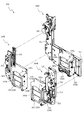
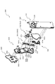
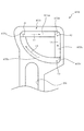
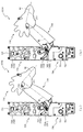
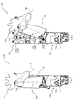
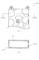
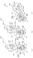
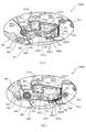
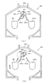
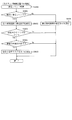
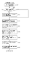
次いで、図5から図8を参照して、動作ユニット200の概略構成について説明する。図5は、動作ユニット200の正面斜視図であり、図6は、動作ユニット200の分解正面斜視図である。また、図7及び図8は、動作ユニット200の正面図である。
Next, a schematic configuration of the
なお、図7では、回転体昇降ユニット300が下降位置に、中央回転ユニット500、右回転ユニット600及び左回転ユニット700が張出位置に、それぞれ配置された状態が図示され、図8では、回転体昇降ユニット300が上昇位置に、中央回転ユニット500、右回転ユニット600及び左回転ユニット700が退避位置に、それぞれ配置された状態が図示される。
7 illustrates a state in which the rotating
図5から図8に示すように、動作ユニット200は、箱状に形成される背面ケース210を備え、その背面ケース210の内部空間には、その下方に回転体昇降ユニット300が、上方に発光装飾ユニット400及び中央回転ユニット500が、左右に右回転ユニット600及び左回転ユニット700が、それぞれ配設される。
As shown in FIG. 5 to FIG. 8, the
背面ケース210は、底壁部211及びその底壁部211の外縁から立設される外壁部212を備え、これら各壁部211,212により一面側(図6紙面左手前側)が開放された箱状に形成される。背面ケース210の底壁部211には、その中央に矩形状の開口211aが開口形成され、背面ケース210が正面視矩形の枠状に形成される。なお、開口211aは、第3図柄表示装置81(図2参照)の外形に対応した(即ち、第3図柄表示装置81を配設可能な)大きさに形成される。
The
回転体昇降ユニット300は、複数(本実施形態では3個)が幅方向に並設される箱状の収容体330と、それら各収容体330にそれぞれ収容される複数(本実施形態では2個)の回転体(第1回転体340a及び第2回転体340b)とを主に備える。
The rotary body lifting / lowering
複数の収容体330は、それぞれ独立して上下方向(図7及び図8の上下方向)に昇降可能に形成される。この場合、下降位置では(図7参照)、第1回転体340a及び第2回転体340bが遊技盤13の背面側に配置され遊技者から視認不能とされる。一方、上昇位置では(図8参照)、第1回転体340a及び第2回転体340bが遊技盤13(センターフレーム86)の開口部まで上昇され、かかる開口部を介して遊技者が視認可能とされる。
The plurality of
第1回転体340a及び第2回転体340bは、収容体330に回転可能に軸支され、その回転により外周面に描かれた複数(本実施形態では3個)の図形を順に遊技者に視認させる。なお、第1回転体340a及び第2回転体340bは、断面三角形の柱状体として形成され、外周の3面にそれぞれ異なる図形が描かれる。
The
本実施形態では、第1回転体340a及び第2回転体340bの駆動源を1の駆動モータ350で共用して、部品コストを削減可能としつつも、これら第1回転体340a及び第2回転体340bの図形の組み合わせを変更可能として、合計9種類の組み合わせを遊技者に視認させることができる(図20参照)。なお、詳細については後述する。
In the present embodiment, the drive source of the
発光装飾ユニット400は、ベース体410と、そのベース体410の中央部分に配設される発光装置420とを主に備え、発光装置420の内部に配設された複数のLED421から発光する光の態様(例えば、照射するLED421の数)を変更することで、発光による演出を行う。なお、詳細については後述する。
The light emitting
中央回転ユニット500は、背面ベース510と、その背面ベース510に基端側が回転可能に軸支される一対の変位部材530とを備え、発光装飾ユニット400の背面側に配設される。一対の変位部材530は、遊技盤13(センターフレーム86)の開口部内に張り出す張出位置(図7参照)と、発光装飾ユニット400の背面側に退避して遊技者から視認不能とされる退避位置(図8参照)との間で回転される。なお、詳細については後述する。
The
右回転ユニット600は、回転体昇降ユニット300の正面ベース315の前面に配設されるベース体(背面ベース610及び正面ベース620)と、そのベース体に基端側が回転可能に軸支される変位部材(第1変位部材630及び第2変位部材640)とを備える。一方、左回転ユニット700は、回転体昇降ユニット300の正面ベース317の前面に配設されるベース体(背面ベース610及び正面ベース620)と、そのベース体に基端側が回転可能に軸支される変位部材(第1変位部材630及び第2変位部材640)とを備える。各変位部材は、遊技盤13(センターフレーム86)の開口部内に張り出す張出位置(図7参照)と、遊技盤13の背面側に退避して遊技者から視認不能とされる退避位置(図8参照)との間で回転される。なお、詳細については後述する。
The
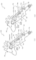
次いで、図9から図60を参照して、回転体昇降ユニット300、発光装飾ユニット400、中央回転ユニット500、右回転ユニット600及び左回転ユニット700の詳細構成を説明する。まず、図9から図22を参照して、回転体昇降ユニット300の詳細構成について説明する。
Next, with reference to FIG. 9 to FIG. 60, detailed configurations of the rotating body lifting / lowering
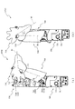
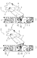
図9は、回転体昇降ユニット300の正面図である。また、図10は、回転体昇降ユニット300の分解正面斜視図であり、図11は、回転体昇降ユニット300の分解背面斜視図である。
FIG. 9 is a front view of the rotating
図9から図11に示すように、回転体昇降ユニット300は、中央の収容体330を昇降させるための中央ユニット300Cと、左右の収容体330をそれぞれ昇降させるための左ユニット300L及び右ユニット300Rとの3ユニットから形成される。左ユニット300Lは、中央ユニット300Cの前面側に重ね合わされ、右ユニット300Rは、中央ユニット300Cの右側端部に連結され、これにより、3個の収容体330が幅方向に並設される。
As shown in FIGS. 9 to 11, the rotary
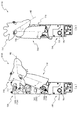
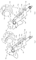
ここで、図12から図19を参照して、中央ユニット300C、左ユニット300L及び右ユニット300Rの詳細構成について説明する。まず、中央ユニット300Cについて、図12及び図13を参照して説明する。図12は、中央ユニット300Cの分解正面斜視図であり、図13は、中央ユニット300Cの分解背面斜視図である。
Here, with reference to FIG. 12 to FIG. 19, the detailed configuration of the
図12及び図13に示すように、中央ユニット300Cは、正面視L字状の背面ベース311と、その背面ベース311の正面側に重ね合わされる正面ベース312と、その正面ベース312の正面側に配設される駆動モータ320と、その駆動モータ320の駆動力により背面ベース311及び正面ベース312に対して昇降される収容体330と、その収容体330に収容される第1回転体340a及び第2回転体340bと、背面ベース311及び正面ベース312の対向面間に収容され駆動モータ320の駆動力を収容体330に伝達する伝達機構と、を主に備える。
As shown in FIGS. 12 and 13, the
中央ユニット300Cにおける伝達機構は、駆動モータ320の駆動軸に固着される駆動ギヤ321と、その駆動ギヤ321に歯合される伝達ギヤ322と、その伝達ギヤ322に歯合されるピニオンギヤ323と、そのピニオンギヤ323に歯合されると共に平板状の部材の側面に歯切りがされたラックとして形成されるラックギヤ324と、そのラックギヤ324が一側に配設されると共に他側に収容体330が配設される連結部材325とを備える。
The transmission mechanism in the
背面ベース311の正面には、一対の軸が突設され、これら各軸に伝達ギヤ322及びピニオンギヤ323が回転可能に軸支される。また、背面ベース311の正面には、スライドガイド351,352が案内方向を上下方向(図12上下方向)とする姿勢で平行に配設され、これらスライドガイド351,352によって連結部材325(ラックギヤ324)及び収容体330が上下方向に案内される。即ち、連結部材325及び収容体330の移動方向が上下方向に規制される。
A pair of shafts project from the front surface of the
よって、駆動モータ320の回転駆動力が、駆動ギヤ321及び伝達ギヤ322を介してピニオンギヤ323に伝達され、ピニオンギヤ323が回転されると、そのピニオンギヤ323の回転運動がラックギヤ324の直線運動に変換され、そのラックギヤ324の直線運動に伴って、連結部材325と共に収容体330が上下方向に変位(昇降)される(図7及び図8参照)。
Therefore, the rotational driving force of the
この場合、連結部材325は、ラックギヤ324が配設される縦長形状の部分と、収容体330が配設される縦長形状の部分とを、それらの下端側どうしを横長形状の部分で連結することで、正面視コ字状に形成される。これにより、左の収容体330が下降位置に配置された状態で、中央の収容体330が上昇位置に配置された場合でも、連結部材325の横長形状の部分を正面ベース312の背面に位置させ、遊技者から視認されることを回避できる。
In this case, the connecting
なお、スライドガイド351は、背面ベース311の正面に形成される案内溝と、その案内溝に沿って摺動可能に形成されると共に連結部材325の背面に固着される摺動体とからなる直線案内機構として形成される。後述する左ユニット300L及び右ユニット300Rにおいても同様である。また、スライドガイド352は、背面ベース311に固着される第1レールと、連結部材325又は収容体330に固着される第2レールと、それら第1レール及び第2レールの間に介在され両者の長手方向への相対変位を許容するための中間レールとからなる伸縮式の直線案内機構として形成される。
The
ここで、中央の収容体330の側方(図12左側)には、左の収容体330が並設されることから(図9参照)、その分、連結部材325の横幅(図12左右方向)寸法が長くなる。更に、上述した通り、遊技者からの視認を回避するために、横長形状の部分が介在されるため、連結部材325が正面視コ字状に形成され、その剛性が低下される。そのため、中央の収容体330の姿勢が不安定となりやすい(左右方向への揺れが発生しやすい)。
Here, since the
これに対し、本実施形態では、中央の収容体330の背面側には、伸縮式の直線案内機構(スライドガイド352)を配設するので、中央の収容体330が上昇位置に配置された状態でも、伸長したスライドガイド352により左右方向への揺れを規制して、中央の収容体330の姿勢を安定させることができる。一方で、中央の収容体330が下降位置に配置された状態では(図9参照)、スライドガイド352を短縮させ、遊技者から視認されることを回避できる。
On the other hand, in this embodiment, the telescopic linear guide mechanism (slide guide 352) is disposed on the back side of the
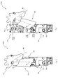
次いで、左ユニット300Lについて、図14及び図15を参照して説明する。図14は、左ユニット300Lの分解正面斜視図であり、図15は、左ユニット300Lの分解背面斜視図である。
Next, the
図14及び図15に示すように、左ユニット300Lは、正面視縦長に形成され中央ユニット300Cの正面ベース312(図12参照)の正面に配設される背面ベース313と、その背面ベース313の正面側に重ね合わされる中間ベース314と、その中間ベース314の正面側に重ね合わされる正面ベース315と、中間ベース314の背面側に配設される駆動モータ320と、その駆動モータ320の駆動力により各ベース313〜315に対して昇降される収容体330と、その収容体330に収容される第1回転体340a及び第2回転体340bと、各ベース313〜315の各対向面間に収容され駆動モータ320の駆動力を収容体330に伝達する伝達機構と、を主に備える。
As shown in FIGS. 14 and 15, the
左ユニット300Lにおける伝達機構は、駆動モータ320の駆動軸に固着される駆動ギヤ321と、その駆動ギヤ321に歯合される伝達ギヤ322a,322bと、伝達ギヤ322bに同軸に固着されるピニオンギヤ323と、そのピニオンギヤ323に歯合されると共に平板状の部材の側面に歯切りがされたラックとして形成されるラックギヤ324と、そのラックギヤ324を収容体330に連結する連結部材326とを備える。
The transmission mechanism in the
中間ベース314の正面には、軸が突設され、この軸に伝達ギヤ322aが回転可能に軸支される。また、中間ベース314には、軸支孔が穿設され、その軸支孔に伝達ギヤ322b及びピニオンギヤ323が同軸に固着された状態で回転可能に軸支される。
A shaft protrudes from the front surface of the
背面ベース313の正面には、スライドガイド351が案内方向を上下方向(図14上下方向)とする姿勢で配設され、このスライドガイド351によって連結部材326(ラックギヤ324)が上下方向に案内される。また、中央ユニット300の正面ベース312(図12参照)の正面には、ガイド板353が締結固定される。ガイド板353には、長穴状の開口である案内溝353aが上下方向に沿って延設され、この案内溝353aには、収容体330の下端側に位置する突出ピンがカラーCを介して内挿される。よって、収容体330は、ガイド板353の案内溝353aに沿って上下方向に案内される。即ち、連結部材326及び収容体330の移動方向が上下方向に規制される。
A
よって、駆動モータ320の回転駆動力が、駆動ギヤ321及び伝達ギヤ322a,322bを介してピニオンギヤ323に伝達され、ピニオンギヤ323が回転されると、そのピニオンギヤ323の回転運動がラックギヤ324の直線運動に変換され、そのラックギヤ324の直線運動に伴って、連結部材326と共に収容体330が上下方向に変位(昇降)される(図7及び図8参照)。
Therefore, the rotational driving force of the
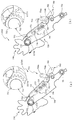
次いで、右ユニット300Rについて、図16を参照して、説明する。図16は、右ユニット300Rの分解正面斜視図である。
Next, the
図16に示すように、右ユニット300Lは、正面略L字状に形成され中央ユニット300Cの背面ベース311(図12参照)の右側端部に連結される配設される背面ベース316と、その背面ベース313の正面側に重ね合わされる正面ベース317と、正面ベース317の正面側に配設される駆動モータ320と、その駆動モータ320の駆動力により背面ベース316及び正面ベース317に対して昇降される収容体330と、その収容体330に収容される第1回転体340a及び第2回転体340bと、背面ベース316及び正面ベース317の対向面間に収容され駆動モータ320の駆動力を収容体330に伝達する伝達機構と、を主に備える。
As shown in FIG. 16, the
右ユニット300Rにおける伝達機構は、駆動モータ320の駆動軸に固着される駆動ギヤ321と、その駆動ギヤ321に歯合されるピニオンギヤ323と、そのピニオンギヤ323に歯合されると共に平板状の部材の側面に歯切りがされたラックとして形成されるラックギヤ324と、そのラックギヤ324を収容体330に連結する連結部材327とを備える。
The transmission mechanism in the
背面ベース316の正面には、軸が突設され、この軸にピニオンギヤ323が回転可能に軸支される。背面ベース316の正面には、スライドガイド351が案内方向を上下方向(図16上下方向)とする姿勢で配設され、このスライドガイド351によって連結部材327(ラックギヤ324)が上下方向に案内される。また、正面ベース316には、長穴状の開口である案内溝316aが上下方向に沿って延設され、この案内溝316aには、収容体330の下端側に位置する突出ピンがカラー(図示せず)を介して内挿される。よって、収容体330は、背面ベース316の案内溝316aに沿って上下方向に案内される。即ち、連結部材327及び収容体330の移動方向が上下方向に規制される。
A shaft protrudes from the front surface of the
よって、駆動モータ320の回転駆動力が、駆動ギヤ321を介してピニオンギヤ323に伝達され、ピニオンギヤ323が回転されると、そのピニオンギヤ323のzがラックギヤ324の直線運動に変換され、そのラックギヤ324の直線運動に伴って、連結部材327と共に収容体330が上下方向に変位(昇降)される(図7及び図8参照)。
Therefore, the rotational driving force of the
上述したように、中央ユニット300Cでは、連結部材325の横幅寸法が長くなり(図12参照)、中央の収容体330の姿勢が不安定となりやすい(左右方向への揺れが発生しやすい)。これに対し、左ユニット300L及び右ユニット300Rでは、左の収容体330及び右の収容体330の側面の近接する位置にラックギヤ323を設けるので、連結部材326,327の横幅(図14及び図16左右方向)寸法を短くして、その剛性を高めることができる。よって、左右の収容体330の姿勢を安定させる(左右方向に揺れ難くする)ことができる。
As described above, in the
これに伴って、左右の収容体330の背面側には、伸縮式の直線案内機構(スライドガイド352)を配設する必要がなく、ガイド板353又は背面ベース316の案内溝353a,316aによる案内により十分に姿勢を安定化できる。その結果、部品コストの削減を図ることができる。
Accordingly, it is not necessary to provide an extendable linear guide mechanism (slide guide 352) on the back side of the left and
次いで、収容体330及びその収容体330に収容される第1回転体340a及び第2回転体340bについて、図17から図19を参照して説明する。
Next, the
図17は、収容体330の分解正面斜視図である。また、図18(a)は、図17の矢印XVIIIa方向視における収容体330の側面図であり、図18(b)は、図18(a)の矢印XVIIIb方向視における収容体330の正面図である。なお、図18(a)及び図18(b)では、側壁体332、隔壁体334及び装飾体335が取り外された状態が図示される。
FIG. 17 is an exploded front perspective view of the
図17及び図18に示すように、収容体330は、基体331と、その基体331の左右に配設される左右の側壁体332,333と、左の側壁体332の内面側に配設される隔壁体334と、基体331の前面に配設される装飾体335とを備え、これら各部331〜335が締結固定により一体化されることで、箱状に形成される。
As shown in FIGS. 17 and 18, the
基体331は、収容体330の背面(図18(b)紙面奥側)、上面および下面(図18(b)上側および下側)を形成する部材であり、3枚の板状の部材を組み合わせて一体に形成される。収容体330の背面を形成する部分には、可視光を反射する鏡として形成される反射部RFが正面に配設される。
The
反射部RFは、正面視矩形状に形成され、第1回転体340a及び第2回転体340bを正面視した場合に、それら両回転体340a,340bよりも少なくとも上下方向に張り出す大きさを有して形成される(図18(b)参照)。
The reflection part RF is formed in a rectangular shape in front view, and has a size that protrudes at least in the vertical direction from both of the
側壁体332,333は、収容体330の左右の側面を形成する矩形板状の部材であり、それぞれ2箇所に保持孔332a,333aが穿設される。保持孔332a,333aは、第1回転体340a及び第2回転体340bの後述する固定軸341が挿通される孔であり、かかる固定軸341を回転不能に保持する。なお、保持孔332a,333aは、その内周面の軸直断面形状が、円形からその円周上の2点を直線で接続して区画される一方を取り除いた形状とされる。
The
隔壁体334は、側壁体332と略同一の外形を有する矩形板状の部材であり、側壁体332との対向面間に伝達ギヤ352及び中間ギヤ354を回転可能に軸支する。また、隔壁体334には、第1ギヤ353及び第2ギヤ355を挿通させるための挿通孔334aが2箇所に穿設される。
The
装飾体335は、収容体330の正面を装飾する部材であり、中央に矩形状の開口335aが形成されることで正面視枠状に形成される。遊技者は、開口335を介して第1回転体340a及び第2回転体340bの回転の態様やそれら両回転体340a,340bの外周面に描かれた図形を視認することができる(図9参照)。
The
このように形成される収容体330には、隔壁体334に配設される駆動モータ350と、その駆動モータ350の駆動力により回転される第1回転体340a及び第2回転体340bと、駆動モータ350の駆動力を第1回転体340a及び第2回転体340bに伝達する伝達機構と、第1回転体340aの回転位置を検出する検出機構とが主に収納される。
The
収容体330における伝達機構は、駆動モータ350の駆動軸に固着される駆動ギヤ351と、その駆動ギヤ351に順に歯合される伝達ギヤ352、第1ギヤ353、中間ギヤ354及び第2ギヤ355からなる歯車列とを備える。伝達ギヤ352及び中間ギヤ354は、側壁体332及び隔壁体334の対向面間に回転可能に保持され、第1ギヤ353及び第2ギヤ355は、第1回転体340a及び第2回転体340bの軸方向端面にそれぞれ固着される。
The transmission mechanism in the
ここで、図19を参照して、第1回転体340a及び第2回転体340bの詳細構成について説明する。図19は、第1回転体340aの分解正面斜視図である。
Here, with reference to FIG. 19, the detailed structure of the 1st
なお、第1回転体340aと第2回転体340bとは、外周面に描かれる図形が異なる点を除き、実質的に同一の構成であるので、以下においては、第1回転体340aを代表例として説明し、第2回転体340bの説明は省略する。
In addition, since the 1st
図19に示すように、第1回転体340aは、固定軸341と、その固定軸341の軸方向両端(軸部341a)に回転可能に軸支される一対の端面板342と、それら一対の端面板342の間に架設される3枚の表示板(第1表示板343A、第2表示板343B及び第3表示板343C)とを主に備える。
As shown in FIG. 19, the first
固定軸341は、胴部341bと、その胴部341bの軸方向両端に連設される軸部341aとを備える。固定軸341は、収容体330の側壁体332,333(図17参照)に回転不能に保持される部位であり、軸方向両端に位置する一対の軸部341aと、一対の軸部341aを接続する胴部341bとを備える。
The fixed
軸部341aは、その軸直断面形状が、円形からその円周上の2点を直線で接続して区画される一方を取り除いた形状(円柱の外周面の一部を平面で面取りした形状)とされ、側壁体332,333の保持孔332a,333a(図17参照)に対して若干小さな相似形状とされる。よって、かかる軸部341aが側壁体332,333の保持孔332a,333aに挿通されることで、固定軸341を収容体330(側壁体332,333)に回転不能に保持することができる。
胴部341bには、複数(本実施形態では4個)のLED344が取着され、そのLED344から発光された光を第1表示板343A〜第3表示板343Cの内面に照射可能とされる。
A plurality (four in this embodiment) of
この場合、胴部341bは、軸部341aが側壁体332,333の保持孔332a,333aに挿通されて回転不能に保持された状態では、LED344の照射方向を収容体330の前面(装飾体335の開口335a、図18(b)紙面手前側の面)へ向けた姿勢(回転位置)で配置される。よって、LED344から発光された光を、第1表示板343A〜第3表示板343Cのうちの収容体330の前面(後述する「視認位置」)に配置された表示板の内面に照射することができる。
In this case, in the state where the
なお、固定軸341(軸部341a、胴部341b)は、軸方向両端が開口した中空の円筒状に形成されるので、かかる内部空間を利用してLED344の配線を取り回すと共にその配線を軸方向端部の開口から収容体330の外部へ引き出すことができる。また、固定軸341は、上述したように、収容体330に対して回転不能とされるので、第1回転体340aが回転されても、LED344の配線に捩じりや引っ張りの外力が作用することを回避できる。
The fixed shaft 341 (the
端面板342は、正面視三角形状に形成される部材であり、中央に軸直断面が円形の軸支孔342aが穿設される。軸支孔342aの内径寸法は、固定軸341の軸部341aの外径寸法よりも若干大きな寸法に設定される。よって、軸支孔342aに軸部341aが挿通されることで、固定軸341に対して端面板342が回転可能に軸支される。これにより、端面板342は、固定軸341を介して、収容体330の内部に回転可能に保持される。
The
ここで、固定軸341は、軸部341aよりも胴部341bが大径に形成されるので、収容体330の側壁体332,333と固定軸341の胴部341bとの間で端面板342の軸方向位置を規定できると共に、端面板342を介して固定軸341を一対の側壁体332,333の間で保持できる。
Here, the fixed
一対の端面板342の一方には、伝達機構における第1ギヤ353が、他方には検出機構における後述する基部ギヤ361が、それぞれ固着される。なお、第2回転体340bには、一対の端面板342の一方には、伝達機構における第2ギヤ355が固着されるが、他方への基部ギヤ361の装着は省略される(図17及び図18参照)。
A
第1表示板343A〜第3表示板343Cは、それぞれ正面視略矩形の板状の部材であり、長手方向両端の外縁を端面板342の外縁(3辺)にそれぞれ接続することで、一対の端面板342の間に架設され、かかる端面板342と共に三角柱状体を形成する。
Each of the
これら第1表示板343A〜第3表示板343Cには、その外面にそれぞれ図形が描かれている。よって、三角柱状体が回転されると、各表示板343A〜343Cの外面にそれぞれ描かれた図形が装飾体335の開口335aを介して順に遊技者に視認可能とされる。
Each of the
第1表示板343A〜第3表示板343Cの外面の少なくとも一部は、固定軸341の軸方向視において、外方へ凸となる円弧状に湾曲して形成される。これにより、後述するように、第1回転体340aと第2回転体340bとの間に回転位置の所定回転角度(例えば、12度)のずれが存在する状態であっても、各表示板343A〜343Cの外面に描かれた図形を視認する遊技者に対し、所定回転角度のずれの認識を困難とさせることができる。
At least a part of the outer surfaces of the
なお、本実施形態では、固定軸341の軸方向視において、第1表示板343A〜第3表示板343Cの幅方向端部が外方へ凸となる円弧状に湾曲して形成される一方、幅方向中央部分が略平坦面状に形成される。これにより、図形の視認性の確保と、回転体340a,340b間のずれの認識を困難とさせることとの両立を図ることができる。また、湾曲して形成される円弧状部分の円弧の半径は、固定軸341の軸心から各表示板343A〜343Cの外面までの最大距離よりも大きくな値(例えば、2倍以上かつ4倍以下)に設定される。
In the present embodiment, when the fixed
ここで、以下においては、三角柱状体が回転される際の第1表示板343A〜第3表示板343Cの配設位置として、収容体330の前面(図18(b)紙面手前側の面)に外面を向けその外面に描かれる図形が装飾体335の開口335aを介して遊技者から視認可能となる位置を「視認位置」と称し、収容体330(基体331)の内面に外面を向けその外面に描かれる図形が装飾体335の開口335aを介して遊技者から視認不能となる位置を「遮蔽位置」と称す。
Here, in the following, as the arrangement positions of the
よって、例えば、第1表示板343Aが視認位置に配置されると、第2表示板343B及び第3表示板343Cが遮蔽位置に配置される(図18(a)及び図18(b)参照)。この状態から三角柱状体が120度だけ正方向または逆方向へ回転されると、第2表示板343B又は第3表示板343Cの一方が視認位置に配置され、第2表示板343B又は第3表示板343Cの他方と第1表示板343Aとが遮蔽位置に配置される。
Therefore, for example, when the
この場合、本実施形態では、第1表示板343Aは、その全体が光を透過させない形態に形成される一方、第2表示板343B及び第3表示板343Cは、光が透過可能な透過部PNを一部に備えて形成される。また、第1表示板343Aの内面には、可視光を反射する鏡として形成される反射部RFが配設される。
In this case, in the present embodiment, the
上述したように、LED344は、第1表示板343A〜第3表示板343Cのうちの視認位置に配置された表示板の内面を照射可能な位置に配置される。よって、視認位置に第2表示板343B又は第3表示板343Cが配置された状態では、LED344から発光された光を、各表示板343B,343Cの透過部PNを透過させて遊技者に直接視認させることができる。
As described above, the
一方、視認位置に第1表示板343Aが配置された状態では(図18(a)及び図18(b)参照)、LED344から発光された光を、第1表示板343Aの内面の反射部RFで反射させ、第2表示板343B又は第3表示板343Cの透過部PNを透過させた後、収容体330の基体331における反射部RFで反射させ、この基体331の反射部RFからの反射光として遊技者に間接的に視認させることができる。
On the other hand, in the state where the
例えば、第1表示板343Aが視認位置に配置される回転位置で第1回転体340aを停止させ、LED344を発光させることで、収容体330の基体331における反射部RFで反射した反射光を視認した遊技者に、その遊技者から視認不能な位置(遮蔽位置)に配置された第2表示板343B又は第3表示板343Cの図形を連想させることができる。これにより、第2表示板343B又は第3表示板343Cの図形が視認可能となる位置に第1回転体340aが回転されることを遊技者に期待させる又は示唆することができる。
For example, the first
特に、本実施形態では、第1回転体340a及び第2回転体340bが断面三角形状に形成されるので、各回転体340a,340bが回転される際には、その回転に伴って、反射板RFと各回転体340a,340bの外面(各表示板343A〜343C)との間の間隔、各回転体340a,340bどうしの外面の間の間隔(図18(b)上下方向間隔)、或いは、各回転体340a,340bの見かけの直径(図18(b)上下方向寸法)を増減させることができると共に、反射板RFに対する各回転体340a,340bの外面(各表示板343Aから343C)の対向角度を変化させることができる。即ち、両回転体340a,340bの回転に伴い、LED344から発光され透過部PNから照射された光を、基体331の反射部RFからの反射光として視認する遊技者に対して、その反射光の態様(例えば、光が視認される領域の大きさ)を周期的に変化させることができる。
In particular, in the present embodiment, the
図17及び図18に戻って説明する。検出機構は、第1回転体340aの端面板342に固着される基部ギヤ361と、その基部ギヤ361に歯合される中間ギヤ362と、その中間ギヤ362に歯合されるギヤであって径方向外方に張り出す被検出板363aを備える末端ギヤ363と、その末端ギヤ363の被検出板363aを検出するセンサ装置364とを備える。
Returning to FIG. 17 and FIG. The detection mechanism includes a
中間ギヤ362及び末端ギヤ363は、側壁体333に回転可能に保持され、センサ装置364は、被検出板363aの移動軌跡上に検出領域を配置した状態で、基体331に配設される。よって、センサ装置364は、被検出板363aの検出状態に基づいて、第1回転体340aの回転位置を検出することができる。即ち、センサ装置364の検出結果に基づいて、第1回転体340a及び第2回転体340bの回転位置を制御する(例えば、任意位置で停止させる)ことができる。
The
次いで、第1回転体340a及び第2回転体340bの回転動作について説明する。駆動モータ350が回転されると、その回転が伝達機構を介して第1回転体340a及び第2回転体340bに伝達され、これら両回転体340a,340bが回転される。
Next, the rotation operation of the
具体的には、駆動モータ350が回転されると、その回転が駆動ギヤ351及び伝達ギヤ352を介して第1ギヤ353に伝達され、第1ギヤ353が回転される。これにより、第1回転体340aが回転される。また、第1ギヤ353が回転されると、その回転が中間ギヤ354を介して第2ギヤ355に伝達され、第2ギヤ355が回転される。これにより、第2回転体340bが第1回転体340aと同方向に回転される。また、駆動モータ350の回転方向が反転されると、第1回転体340a及び第2回転体340bが上述した場合とは逆方向に回転される。
Specifically, when the
その結果、遊技者に視認される第1回転体340aの図形と第2回転体340bの図形との組み合わせが順に変更される。この場合、両回転体340a,340bの図形の組み合わせは、従来品では、3組に限定されていた。
As a result, the combination of the graphic of the
即ち、第1回転体340aと第2回転体340bとが1の駆動モータにより同期して回転駆動されるため、形成可能な組み合わせは、例えば、第1回転体340aの第1表示板343Aと第2回転体340bの第1表示板343Aとを表示位置に配置する第1の組み合わせ、第1回転体340aの第2表示板343Bと第2回転体340bの第2表示板343Bとを表示位置に配置する第2の組み合わせ、第1回転体340aの第3表示板343Cと第2回転体340bの第3表示板343Cとを表示位置に配置する第3の組み合わせの3組のみであった。
That is, since the
一方で、第1回転体340aと第2回転体340bとをそれぞれ異なる駆動モータにより独立して回転駆動する構造を採用することで、最大9組の組み合わせを形成することができると共に、その組み合わせを任意に現出させることができる。しかしながら、この場合には、2個の駆動モータを必要とする分、部品コストの増加を招く。
On the other hand, by adopting a structure in which the
これに対し、本実施形態では、駆動モータ350の数を1個のみに抑えつつ、第1回転体340a及び第2回転体340bの図形の組み合わせを9組形成することができると共に、その組み合わせを任意に現出させることができる。また、本実施形態では、第1回転体340a及び第2回転体340bの回転位置の完全一致を要求せず、回転位置の所定量のずれを許容することで、9組の組み合わせを速やかに現出させることができる。この両回転体340a,340bの図形の組み合わせについて、図20及び図21を参照して説明する。
On the other hand, in the present embodiment, nine combinations of figures of the first
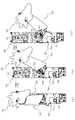
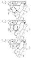
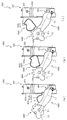
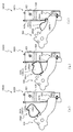
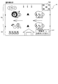
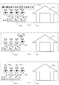
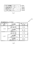
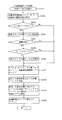
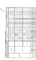
図20は、第1回転体340a及び第2回転体340bの図形の組み合わせを示すテーブルである。また、図21及び図22は、第1回転体340a及び第2回転体340bが回転される際の遷移状態を示す第1回転体340a及び第2回転体340bの側面模式図であり、図21(a)から図21(e)は、図20にNo.1〜5として示す状態に、図22(a)から図22(e)は、図20にNo.6〜10として示す状態に、それぞれ対応する。
FIG. 20 is a table showing combinations of figures of the first
なお、図20では、第1回転体340a及び第2回転体340bの図形の組み合わせとして、視認位置に第1表示板343Aが配置された状態が符号「A」又は「A’」により、視認位置に第2表示板343Bが配置された状態が符号「B」又は「B’」により、視認位置に第3表示板343Cが配置された状態が符号「C」又は「C’」により、それぞれ表される。
In FIG. 20, as a combination of figures of the first
例えば、図20のNo.10「A,C’」で表される状態は、第1回転体340aの第1表示板343Aと第2回転体340bの第3表示板343Cとがそれぞれ視認位置に配置され、第1回転体340aからは第1表示板343Aに描かれる図形が、第2回転体340bからは第3表示板343Cに描かれる図形が、それぞれ遊技者に視認される状態に対応する。
For example, in FIG. 10 "A, C '" indicates that the
また、図21では、図面を簡素化して、理解を容易とするために、第1回転体340aの第1表示板343A〜第3表示板343Cを符号「A〜C」を用いて、第2回転体340bの第1表示板343A〜第3表示板343Cを符号「A’〜C’」を用いて、それぞれ図示する。
In FIG. 21, in order to simplify the drawing and facilitate understanding, the first display plate 343 </ b> A to the third display plate 343 </ b> C of the first
ここで、第1回転体340a及び第2回転体340bは、それぞれに固着される第1ギヤ353及び第2ギヤ355の歯数が異なる値に設定される。本実施形態では、第1ギヤ353の歯数が14に、第2ギヤ355の歯数が20とされる、第1回転体340aを120度回転させると、第2回転体340bが108度回転するように形成される。
Here, the first
図20のNo.1及び図21(a)に示すように、第1回転体340aの第1表示板343A及び第2回転体340bの第1表示板343Aをそれぞれ視認位置に配置した状態から(図20のNo.1「A’,A」、第1の組み合わせ)、第1回転体340aを120度回転させその第2表示板343Bを視認位置に配置させると、図20のNo.2及び図21(b)に示すように、第2回転体340bは第2表示板343Bを視認位置に配置させる。これにより、第2の組み合わせ(図20のNo.2「B’,B」)を形成することができる。
No. in FIG. As shown in FIG. 1 and FIG. 21A, the
この場合、第1回転体340aの120度の回転に対し、第2回転体340bの回転は108度であるので、両者の回転位置に12度の差異(ずれ)が生じるが、各回転体340a,340bを軸直角方向から視認する遊技者が、その12度の回転角度の差異を認識することは困難であり、その結果、第1回転体340a及び第2回転体340bの各第2表示板343Bの外面に描かれた図形がそれぞれ視認位置に配置された(第2の組み合わせが形成された)と認識させることができる。
In this case, since the rotation of the second
特に、本実施形態では、上述したように、第1表示板343A〜第3表示板343Cの外面が、固定軸341の軸方向視において、外方へ凸となる円弧状に湾曲して形成される(即ち、図形が描かれる面が各回転体340a,340bの回転方向に沿って湾曲される)ので、これら各表示板343A〜343Cの外面に描かれた図形を正面視する遊技者に対し、第1回転体340a及び第2回転体340bの回転位置の相違(ずれ)を認識させることを困難とさせることができる。
In particular, in the present embodiment, as described above, the outer surfaces of the
図20のNo.2及び図21(b)に示す状態から、第1回転体340aを120度回転させその第3表示板343Cを視認位置に配置させると、図20のNo.3及び図21(c)に示すように、第2回転体340bはその回転位置を第1回転体340aに対して位置ずれされた位置に配置する。即ち、この状態では、両者の間に24度の回転角度の差異が形成されるため、遊技者に図形のずれ(組み合わせの非成立、図20のNo.3「−,C」)を認識させることができる。
No. in FIG. 2 and the state shown in FIG. 21B, when the first
同様に、図20のNo.4及び図21(d)に示す状態から図20のNo.9及び図22(d)に示す状態までの区間の回転では、第1回転体340aは、その120度の回転毎に各表示板343A〜343Cを視認位置に配置させる一方で、第2回転体340bはその回転位置を第1回転体340aに対して位置ずれさせた位置に配置する。その結果、遊技者に図形のずれ(組み合わせの非成立、図20のNo.4「−,A」〜No.9「−,C」)を認識させることができる。
Similarly, in FIG. 4 and the state shown in FIG. 9 and the rotation of the section up to the state shown in FIG. 22 (d), the first
図20のNo.9及び図22(d)に示す状態から(図20のNo.9「−,C」)、第1回転体340aを120度回転させその第1表示板343Aを視認位置に配置させると、図20のNo.10及び図22(e)に示すように、第2回転体340bは第3表示板343Cを視認位置に配置させる。これにより、第3の組み合わせ(図20のNo.10「C’,A」)を形成することができる。
No. in FIG. 9 and FIG. 22 (d) (No. 9 “−, C” in FIG. 20), the first
なお、本実施形態によれば、図形のずれ(組み合わせの非成立、図20のNo.3「−,C」〜No.9「−,C」)が形成される区間においても、第2回転体340bの回転を継続させ、遊技者から視認される図形を切り替え続けることができるため、第3の組み合わせにおいて、いずれの図形が組み合わされるのかを遊技者に予測困難とさせることができる。
Note that, according to the present embodiment, the second rotation is also performed in the section in which the figure shift (combination failure, No. 3 “−, C” to No. 9 “−, C” in FIG. 20) is formed. Since the rotation of the
以降は、上述した態様(図20のNo.1及び図21(a)に示す状態から図20のNo.9及び図22(e)に示す状態までの区間の回転)と実質的に同一の態様が、更に2回繰り返されることで、1サイクルが完了される(テーブルが始点から終点まで一巡される)。 Thereafter, substantially the same as the above-described mode (the rotation of the section from the state shown in No. 1 and FIG. 21A of FIG. 20 to the state shown in No. 9 and FIG. 22E of FIG. 20). By repeating the mode twice more, one cycle is completed (the table is cycled from the start point to the end point).
この場合、図20のNo.11〜No.20に示す状態の区間では、図21及び図22における第1回転体340aの位相を120度異ならせた状態に置き換えて考えれば良く、第4の組み合わせ(図20のNo.11「A’,B」)、第5の組み合わせ(図20のNo.12「B’,C」)及び第6の組み合わせ(図20のNo.20「C’,B」)を形成することができる。
In this case, no. 11-No. 20 may be replaced with a state in which the phase of the first
また、図20のNo.21〜No.30に示す状態の区間では、図21及び図22における第1回転体340aの位相を240度異ならせた状態に置き換えて考えれば良く、第7の組み合わせ(図20のNo.21「A’,C」)、第8の組み合わせ(図20のNo.22「B’,A」)及び第9の組み合わせ(図20のNo.30「C’,C」)を形成することができる。
In addition, in FIG. 21-No. 30 may be replaced with a state in which the phase of the first
以上のように、本実施形態によれば、駆動モータ350の回転を第1回転体340a及び第2回転体340bのそれぞれへ伝達する伝達機構が、複数の歯車(駆動ギヤ351〜第2ギヤ355の5枚の歯車)からなる歯車列として形成され、駆動モータ350の回転を、第1回転体340a及び第2回転体340bへそれぞれ異なる回転比で伝達可能に形成される。
As described above, according to the present embodiment, the transmission mechanism that transmits the rotation of the
これにより、第1回転体340aの回転周期と第2回転体340bの回転周期とを異ならせることができる。その結果、1個の駆動モータ350のみであっても、第1回転体340a及び第2回転体340bの図形の組み合わせを9組形成することができると共に、その組み合わせを任意に変更できる(所望の組み合わせを任意に現出させることができる)。
Thereby, the rotation period of the 1st
また、伝達機構が歯車列として形成されることで、構造を簡素化して、部品コストの削減と耐久性および信頼性の向上とを図ることができるだけでなく、各歯車が常に歯合されているので、駆動モータ350の回転方向を正逆切り替えることで、図20に示すテーブルの進行方向を切り替えることができる。
In addition, since the transmission mechanism is formed as a gear train, not only can the structure be simplified, the cost of parts can be reduced and the durability and reliability can be improved, but the gears are always meshed. Therefore, the traveling direction of the table shown in FIG. 20 can be switched by switching the rotation direction of the
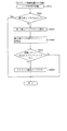
よって、例えば、図20のテーブルを正方向(図20下方向)へ進行し、図形のずれ(組み合わせの非成立)が形成される区間(例えば、図20のNo.3〜No.9)を経て、第3の組み合わせ(図20のNo.10「C’,A」)を現出させた後または現出させた直前で、駆動モータ350の回転方向を逆転させ、図20のテーブルを逆方向(図20上方向)へ戻るという一連の動作を繰り返すことができ、これにより、第3の組み合わせの現出を遊技者に期待させるという演出を行うことができる。
Therefore, for example, the table in FIG. 20 proceeds in the forward direction (downward in FIG. 20), and sections (for example, No. 3 to No. 9 in FIG. 20) in which a graphic shift (combination of combinations) is formed. Then, after the third combination (No. 10 “C ′, A” in FIG. 20) appears or just before it appears, the rotation direction of the
或いは、例えば、第1の組み合わせ(図20のNo.1「A’,A」)が形成された状態から、第9の組み合わせ(図20のNo.30「C’,C」)を現出させる必要がある場合に、図20のテーブルを正方向(図20下方向)へ進行して、第9の組み合わせを現出させることに加え、図20のテーブルを逆方向(図20上方向)へ進行して、第9の組み合わせを現出させることもできる。即ち、前者の場合には、第1回転体340aの120度の回転を30回繰り返すことが必要となるのに対し、後者の場合には、第1回転体340aの120度の回転を1回行えば良いので、所望の図形の組み合わせを速やかに現出させることができる。
Alternatively, for example, the ninth combination (No. 30 “C ′, C” in FIG. 20) appears from the state in which the first combination (No. 1 “A ′, A” in FIG. 20) is formed. 20 is advanced in the forward direction (downward in FIG. 20) and the ninth combination appears in addition to the table in FIG. 20 in the reverse direction (upward in FIG. 20). To the 9th combination. That is, in the former case, the 120-degree rotation of the first
ここで、第1回転体340aの120度の回転に対して、第2回転体340bを60度回転させる構成とした場合(即ち、第2回転体340bの回転を、第1回転体340aの回転に対し、「1/整数」倍に設定した場合)には、第1回転体340a及び第2回転体340bの回転位置に差異(ずれ)を発生させることなく、図形の組み合わせを複数形成することができる。しかしながら、この場合には、図形の組み合わせ可能な数が最大3組となる。
Here, when the second
これに対し、本実施形態では、上述したように、第1、第4及び第7の組み合わせ(図20のNo.1「A’,A」、No.11「A’,B」及びNo.21「A’,C」)を除き、残りの6組の組み合わせ(第2、第3、第5、第6、第8及び第9の組み合わせ)において、第1回転体340a及び第2回転体340bの回転位置に所定回転角度の差異(ずれ)が発生することを許容する。これにより、図形の組み合わせ可能な数を9組とすることができる。
On the other hand, in the present embodiment, as described above, the first, fourth and seventh combinations (No. 1 “A ′, A”, No. 11 “A ′, B” and No. 11 in FIG. 21 “A ′, C”), and the remaining six combinations (second, third, fifth, sixth, eighth, and ninth combinations), the first
即ち、第1回転体340a及び第2回転体340bを1の駆動モータ350により回転させる構造において、図形の組み合わせ可能な数を9組とすることは、駆動モータ350の回転を第1回転体340a及び第2回転体340bのそれぞれへ伝達する伝達機構が歯車列として形成されるだけでは達成不可能であり、本実施形態のように、第1回転体340a及び第2回転体340bの回転位置に所定回転角度の差異(ずれ)が生じることを許容することで初めて可能となったものである。これにより、図形の組み合わせ可能数の増加による演出効果の向上を図りつつ、駆動モータ350の必要数を抑制して、製品コストの削減を図ることができる。
That is, in the structure in which the
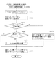
この場合、第1回転体340a及び第2回転体340bの回転位置に所定回転角度の差異(ずれ)が生じる図形の組み合わせ(第2、第3、第5、第6、第8及び第9の組み合わせ)では、第1回転体340a及び第2回転体340bを停止させる停止位置を補正するようにしても良い。
In this case, combinations of figures (second, third, fifth, sixth, eighth, and ninth) that cause a difference (shift) in a predetermined rotation angle at the rotation positions of the first
例えば、第2、第5及び第8の組み合わせ(図20のNo.2「B’,B」、No.12「B’,C」及びNo.22「B’,A」)では、図21(b)に示すように、第2回転体340bの位相が遅れるので、第1回転体340aを所定角度だけ位相を進めた回転位置で停止させる。即ち、基準面からの位置ずれが第2回転体340bのみに集中されているので、図21(a)に示す状態から第1回転体340aを120度回転させた回転位置で停止させるのではなく、例えば、126度回転させた回転位置で停止させる。これにより、基準面からの位置ずれを第1回転体340a及び第2回転体340bに分散させて、目立たなくすることができる。
For example, in the second, fifth and eighth combinations (No. 2 “B ′, B”, No. 12 “B ′, C” and No. 22 “B ′, A” in FIG. 20), FIG. As shown in (b), since the phase of the
同様に、例えば、第3、第6及び第9の組み合わせ(図20のNo.10「C’,A」、No.20「C’,B」及びNo.30「C’,C」)では、図22(e)に示すように、第2回転体340bの位相が先行されるので、第1回転体340aを所定角度だけ位相を遅らせた回転位置で停止させる。即ち、基準面からの位置ずれが第2回転体340bのみに集中されているので、図22(d)に示す状態から第1回転体340aを120度回転させた回転位置で停止させるのではなく、例えば、114度回転させた回転位置で停止させる。これにより、基準面からの位置ずれを第1回転体340a及び第2回転体340bに分散させて、目立たなくすることができる。
Similarly, for example, in the third, sixth and ninth combinations (No. 10 “C ′, A”, No. 20 “C ′, B” and No. 30 “C ′, C” in FIG. 20), As shown in FIG. 22E, since the phase of the second
上述したように、回転体昇降ユニット300は、各収容体300が上下方向に昇降可能に形成され、下降位置では(図7参照)、第1回転体340a及び第2回転体340bを遊技盤13の背面に位置させて遊技者から視認不能とできる。よって、第1回転体340aの図形と第2回転体340bの図形との組み合わせのうちの所望の組み合わせを必要なタイミングで速やかに現出させることができる。
As described above, the rotary body lifting / lowering
即ち、本実施形態では、9組の図形の組み合わせが形成可能であるが故に、テーブルが長くなる(図20のテーブルの段数が多くなる)ため、所望の組み合わせを現出させるためには、第1回転体340a及び第2回転体340bを比較的多く回転させる必要があり、その分、時間が嵩む。
That is, in this embodiment, since nine combinations of figures can be formed, the table becomes long (the number of stages of the table in FIG. 20 increases). It is necessary to rotate the 1st
これに対し、本実施形態では、各収容体300を下降位置に配置することで(図7参照)、第1回転体340a及び第2回転体340bを遊技者から視認不能な位置に退避させることができる。これにより、第1回転体340a及び第2回転体340bの回転を遊技者に認識されることなく、その回転位置を所定の回転位置まで事前に回転させておくことができ、その結果、必要なタイミングが到来した際には、各収容体300を上昇位置に配置し(図8参照)、第1回転体340a及び第2回転体340bの残りの回転を実行することで、所望の組み合わせを速やかに現出させることができる。
On the other hand, in this embodiment, by disposing each
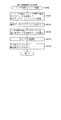
なお、各収容体300の下降位置への配置は、特定の変動パターンで第1回転体340a及び第2回転体340bを回転させる際にのみ行うようにしても良い。例えば、第1回転体340a及び第2回転体340bの回転の開始から結果の表示(回転の停止)までの時間が比較的短い変動パターンでは、各収容体300を下降位置へ配置せず、各回転体340a,340bの回転の開始から停止を、遊技者から視認可能な位置で行う一方、各回転体340a,340bの回転の開始から結果の表示(回転の停止)までの時間が比較的長い変動パターンでは、各回転体340a,340bの事前の回転を遊技者から視認不能な位置で行うようにしても良い。
In addition, you may make it arrange | position to the descending position of each
この場合、本実施形態では、第1回転体340a及び第2回転体340bの下降位置における事前の回転は、所定の動作手段が動作される場合に行われる。これにより、第1回転体340a及び第2回転体340bの事前の回転が遊技者に認識されることを抑制することができる。
In this case, in the present embodiment, the advance rotation at the lowered position of the first
即ち、第1回転体340a及び第2回転体340bを回転させる際には、比較的大きな音が発生するため、下降位置に移動されて、遊技者から視認不能とされたとしても、その回転時に発生する音によって第1回転体340a及び第2回転体340bが事前に回転されていることを、遊技者に認識させてしまうおそれがある。
That is, when the
これに対し、第1回転体340a及び第2回転体340bの回転を、所定の動作手段の動作時に行うことで、その動作に紛れ込ませることができる。その結果、第1回転体340a及び第2回転体340bの事前の回転を遊技者に認識させ難くすることができる。
On the other hand, when the rotation of the first
なお、動作手段としては、例えば、払出装置133、音声出力装置226、或いは、球発射ユニット112a(いずれも図3又は図4参照)が例示される。これらの動作手段が動作されている状態では、例えば、球の払出、音声の出力、或いは、球の発射に伴い、比較的大きな音が発生する。よって、遊技者に第1回転体340a及び第2回転体340bの事前の回転を認識させ難くできる。
In addition, as an operation | movement means, the
なお、これに代えて、或いは、これに加えて、第3図柄表示装置81(図2参照)において表示される演出が所定の演出である場合に、第1回転体340a及び第2回転体340bの事前の回転を行うようにしても良い。第3図柄表示装置81に表示される演出が所定の演出である場合には、その所定の演出に遊技者の意識を集中させることができるため、その分、第1回転体340a及び第2回転体340bの事前の回転を遊技者に認識させ難くできる。
Instead of or in addition to this, when the effect displayed on the third symbol display device 81 (see FIG. 2) is a predetermined effect, the
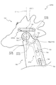
次いで、図23から図25を参照して、発光装飾ユニット400について説明する。図23は、発光装飾ユニット400の正面図である。また、図24は、発光装飾ユニット400の分解正面斜視図であり、図25は、発光装飾ユニット400の分解背面斜視図である。
Next, the light emitting
図23から図25に示すように、発光装飾ユニット400は、背面ケース210の底壁部211(図6参照)に配設される正面視横長矩形のベース体410と、そのベース体410の幅方向中央前面に配設される発光装置420と、その発光装置420の前面に覆設される遮光部材430と、その遮光部材430の前面に覆設されると共に光透過性材料からなるカバー部材440と、それら発光装置420、遮光部材430及びカバー部材440の周囲を取り囲む正面視円環状の外周装飾体450,460と、を主に備える。
As shown in FIGS. 23 to 25, the light emitting
発光装置420の前面側には、複数(本実施形態では15個)の発光体(LED421)が全面にわたって分散された状態で配設され、遮光部材430の背面へ光を照射可能に形成される。ここで、遮光部材430は、遮光材料(光非透過性材料)から形成される本体部431と、その本体部431の前面および背面から立設される区画壁432とを備える。
On the front side of the
遮光部材430の本体部431には、正面視円形の開口431aが複数箇所(本実施形態では15箇所)に開口形成される。これら複数の開口431aは、正面視において、発光装置420の複数のLED421のそれぞれに対応する位置に配設される。よって、LED421から発光された光を、遮光部材430の開口431aを通して、カバー440の背面へ到達させることができる。
In the
区画壁432は、本体部431よりも小径となる正面視円環形状に形成され、本体部431の中心から偏心した位置に配設される。これにより、発光装置420とカバー体440との間の空間が、区画壁432により囲まれる正面視円形の第1の空間と、区画壁431の外周側に位置にする正面視略三日月状の第2の空間とに区画される。
The
このように、区画壁431による区画が形成されることで、カバー部材440から視認される光の輪郭を明確にすることができる。即ち、第1の空間内のLED421のみを発光した場合には円形を、第2の空間内のLED421のみを発光した場合には三日月形状を、視認させることができる。
In this way, by forming the partition by the
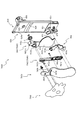
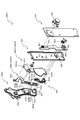
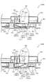
次いで、図26から図28を参照して、中央回転ユニット500について説明する。図26(a)は、退避位置に配置された状態における中央回転ユニット500の正面図であり、図26(b)は、張出位置に配置された状態における中央回転ユニット500の正面図である。また、図27は、中央回転ユニット500の分解正面斜視図であり、図28は、中央回転ユニット500の分解背面斜視図である。
Next, the
図26から図28に示すように、中央回転ユニット500は、背面ケース210の底壁部211(図6参照)に配設される背面ベース510と、その背面ベース510の正面に重ね合わされる正面ベース520と、それら背面ベース510及び正面ベース520に基端側が回転可能に軸支される一対の変位部材530と、その変位部材530を回転駆動するための駆動力を発生する駆動モータ540と、その駆動モータ540の駆動力を変位部材530へ伝達する伝達機構と、を主に備える。
As shown in FIGS. 26 to 28, the central
背面ベース510の正面および正面ベース520の背面には、変位部材530の基端側(回転軸531)を回転可能に軸支するための軸支孔511,521がそれぞれ凹設される。また、背面ベース510の正面には、伝達機構におけるクランク歯車542を回転可能に軸支するための支持軸512が突設される。
Shaft support holes 511 and 521 for rotatably supporting the base end side (rotating shaft 531) of the
変位部材530は、先端側の正面に装飾が施された部材であり、回転軸531と、連結歯車532と、クランク溝533と、を主に備える。回転軸531は、上述したように、背面ベース510及び正面ベース520の軸支孔511,521に軸支される軸であり、変位部材530の基端側における正面および背面から突設される。
The
連結歯車532は、変位部材530の基端側の外周面に回転軸531を回転中心として刻設される歯車である。連結歯車532は、一方の変位部材530が回転軸531を中心として回転された場合に、その回転を相手の連結歯車532へ伝達して回転させる。これにより、他方の変位部材530が回転軸531を中心として回転される。
The
クランク溝533は、伝達機構の後述するクランク歯車542の連結ピン542aが摺動可能に挿通される正面視直線状の溝であり、一対の変位部材530のうちの一方(図27左側、図28右側)の変位部材530の背面に凹設される。後述するように、クランク歯車542の回転が連結ピン542aを介してクランク溝533に伝達されることで、一方の変位部材530が回転軸531を中心として回転される。
The
伝達機構は、上述したように、駆動モータ540の駆動力を変位部材530へ伝達するための機構であり、駆動モータ540の駆動軸に固着されるピニオン541と、そのピニオン541に歯合されるクランク歯車542と、を主に備える。クランク歯車542は、その回転中心(支持軸512)から偏心する位置に突設され変位部材530のクランク溝533に挿通される連結ピン542aを備える。
As described above, the transmission mechanism is a mechanism for transmitting the driving force of the
このように構成される中央回転ユニット500によれば、駆動モータ540の駆動軸の回転が、ピニオン541を介してクランク歯車542に伝達され、クランク歯車542が回転されると、そのクランク歯車542の回転に伴って、連結ピン542aが円弧状の軌跡を描きつつ変位され、その連結ピン542aの変位がクランク溝533の内壁面に作用することで、一方(図27左側、図28右側)の変位部材530が回転軸531を回転中心として回転される。この場合、連結歯車532を介して、他方の変位部材530も同期して回転される。その結果、一対の変位部材530が、遊技盤13(センターフレーム86)の開口部内に張り出す張出位置(図7及び図26(a)参照)と、発光装飾ユニット400の背面に退避される退避位置(図8及び図26(b)参照)との間で回転可能とされる。
According to the
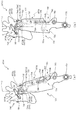
次いで、図29から図40を参照して、右回転ユニット600について説明する。図29は、右回転ユニット600の分解正面斜視図であり、図30及び図31は、右回転ユニット600の分解背面斜視図である。なお、図31では、右回転ユニット600の一部が組み立てられた状態が図示される。
Next, the
図29から図31に示すように、右回転ユニット600は、背面ベース610及び正面ベース620からなるベース体と、そのベース体の正面ベース620の正面側に変位可能に配設される第1変位部材630及び第2変位部材640と、それら第1変位部材630及び第2変位部材640を変位させるための駆動力を発生すると共に背面ベース610の背面に配設される駆動モータ650と、その駆動モータ650の駆動力を伝達する伝達機構と、を主に備える。
As shown in FIGS. 29 to 31, the
背面ベース610及び正面ベース620の対向面間には、伝達機構の一部(第1ピニオン651、ラック部材652及び第2ピニオン653)が収納される。正面ベース620の背面には、第1ピニオン651を回転可能に軸支するための軸受凹部621が凹設されると共に、ラック部材652の移動方向を規定するためにそのラック部材652の摺動溝652aに挿通される一対の挿通ピン622が突設される。
A part of the transmission mechanism (the
また、正面ベース620には、第1変位部材630の回転軸631及び伝達部材654の回転軸654aをそれぞれ回転可能に軸支するために貫通形成される正面視円形の軸支孔624,625が正面ベース620の幅方向(短手方向)に所定の間隔を隔てつつ並設される。
Further, the
なお、第1変位部材630を軸支する軸支孔624が、伝達部材654を軸支する軸支孔625よりも遊技盤13の開口側(第1変位部材630の張出位置側、図29左側)に配設されるので、後述するように、張出位置において、第1変位部材630及び第2変位部材640が遊技盤13の開口側へ張り出す張り出し面積を確保できる一方で、退避位置および張出位置の間で、第1変位部材630の背面に伝達部材654を隠しやすくすることができる。
It should be noted that the
正面ベース620の正面には、凸条626及び軸受部627が突設される。凸条626は、正面ベース620の幅方向に沿って延設される横長の突部であり、断面が略三角形状に形成される。凸条626は、その頂部が、正面視において、軸支孔624を中心とする円弧状に湾曲して形成される。第2変位部材640(連結変位部材642)が変位する際には、凸条626の頂部を接触させることができ、後述するように、正面ベース620の正面が全面で面当たりする場合と比較して、接触面積を小さくして、摺動抵抗を抑制することができると共に、光透過性材料からなる連結変位部材642に擦れにより曇りが形成されることを抑制できる。
On the front surface of the
正面ベース620の正面視左側(図29左側、即ち、遊技盤13の開口側)には、その側面および前面の稜線部分を面取りすることで傾斜して形成される傾斜面620aが配設される。よって、後述するように、退避位置へ退避する際に、第2変位部材640(連結変位部材642)が正面ベース620の側面に係止されて変位できなくなることを抑制できる(図33参照)。
On the left side of the
軸受部627は、軸支孔624と同心の筒状体として形成され、その内周面で第1変位部材630の回転軸631を軸支孔624と共に回転可能に軸支する。軸受部627の外周面からは、突出部628が径方向外方であって正面ベース620の下方へ向けて突出して形成される。突出部628によって、第1変位部材630の回転を所定範囲に規制する共に、第1変位部材630の前方への傾倒を抑制することができる。その詳細については後述する(図40参照)。
The bearing
なお、本実施形態では、正面ベース620の背面に軸受凹部621が凹設されることで、かかる軸受凹部621を利用して、第1ピニオン651を背面ベース610及び正面ベース620の対向面間に回転可能に保持できる。そのため、第1ピニオン651を駆動モータ650の駆動軸に締結固定することを不要とできるので、部品点数を削減して、部品コスト及び組立コストの削減を図ることができる。
In the present embodiment, since the
一方で、正面ベース620の背面に軸受凹部621が凹設されると、その凹設に伴い、正面ベース620の正面から突出部分623が突出される。本実施形態では、第1変位部材630の先端側に第2変位部材640の一部が軸支されるため、第1変位部材630及び第2変位部材640が変位される際には、前後方向に揺れが生じやすく、よって、突出部分623に第2変位部材640が干渉する恐れがあるが、かかる干渉を凸条626により抑制可能に形成される。その詳細については後述する(図39参照)。
On the other hand, when the
伝達機構は、駆動モータ650の駆動軸に装着される第1ピニオン651と、伝達部材654の回転軸654aに締結固定される第2ピニオン653と、それら第1ピニオン651及び第2ピニオン653が歯合されるラックギヤを平板状の部材の側面に歯切りしたラックとして形成されるラック部材652と、を備える。
The transmission mechanism includes a
ラック部材652は、その長手方向に沿って延設される正面視長穴状の摺動溝652aを2本備え、これら各摺動溝652aに正面ベース620の一対の挿通ピン622がそれぞれ挿通されることで、その移動方向が規定された状態で保持される。即ち、背面ベース610及び正面ベース620の対向面間にラック部材652が直線運動可能に保持される。
The
伝達部材654は、一端側の背面から突設される回転軸654aと、その回転軸654aと反対側となる他端側の正面から突設される駆動ピン654bと、それら回転軸654a及び駆動ピン654bの間を正面視円弧状に凹欠して形成される凹欠部654cとを備え、回転軸654aが軸支孔625に挿通されることで、正面ベース620の正面側に回転可能に軸支される。
The
駆動ピン654bは、断面円形の軸状体であり、第1変位部材630及び第2変位部材640の後述する第1溝635及び第2溝641bに挿通される。凹欠部654cの正面視における円弧形状は、正面ベース620の軸受部627の外形に対応する形状(即ち、軸受部627をその内周側に受け入れ可能な形状)に形成される。
The
よって、伝達部材654の回転軸654aの配設位置を第1変位部材630の回転軸631の配設位置に近接させつつ、正面ベース620の軸受部627に干渉することを抑制して、伝達部材654の回転可能範囲を大きくできる。従って、後述するように、右回転ユニット600全体の小型化を図りつつ、第1変位部材630及び第2変位部材640をより大きく変位させることができる(図37及び図38参照)。
Accordingly, the
伝達機構によれば、駆動モータ650の回転駆動力により第1ピニオン651が回転されると、その第1ピニオン651の回転が、ラック部材652の直線運動を介して、第2ピニオン653に伝達され、第2ピニオン653が回転されることで、伝達部材654が正面ベース620の軸支孔625を回転中心として回転される。後述するように、伝達部材654を回転させ、その駆動ピン654bを第1溝635及び第2溝641bに作用させることで、第1溝635及び第2溝641bの形状に応じた変位を、第1変位部材630及び第2変位部材640のそれぞれに独立して行わせることができる(図37及び図38参照)。
According to the transmission mechanism, when the
第1変位部材630の背面には、回転軸631、支持軸632,633及び当接部634がそれぞれ突設されると共に、第1溝635が凹設される。回転軸631は、上述したように、正面ベース620の軸支孔624に挿通される軸状体であり、かかる回転軸631及び軸支孔624を介して、第1変位部材630が正面ベース620に回転可能に軸支される。なお、回転軸631の軸方向端面には、軸支孔624の内径よりも大径の保持体Cが締結固定され、これにより、回転軸631の軸支孔624からの抜け出しが規制される。
On the back surface of the
支持軸632、633は、第2変位部材640の被駆動部材641及び連結変位部材642をそれぞれ回転可能に軸支するための断面円形の軸状体である。即ち、第2変位部材640の被駆動部材641及び連結変位部材642は、支持軸632、633を介して、第1変位部材630の背面にそれぞれ回転可能に保持される。
The
当接部634は、回転軸631を中心として周方向に所定の間隔を隔てつつ一対が配設される。これら一対の当接部634の間には、正面ベース620に第1変位部材630が組み付けられた状態において、正面ベース620の突出部628が配設される。よって、後述するように、正面ベース620に対して第1変位部材630が回転軸631を中心として回転される場合に、当接部634が正面ベース620の突出部628の側面に当接されることで、正面ベース620に対する第1変位部材630の回転を所定の範囲内に規制できる。
A pair of abutting
第1溝635は、伝達部材654の駆動ピン654bが摺動可能に挿通される凹溝であり、正面視略くの字状に屈曲して形成される。詳細には、第1溝635は、第1変位部材630の長手方向に沿って直線状に延設される作用区間635aと、回転軸631側を凹とする円弧状に湾曲しつつ第1変位部材630の幅方向に沿って延設される(即ち、回転軸631と同心の円環形状を分断した形状に形成される)非干渉区間635bとを備える。なお、後述するように、作用区間635aは、伝達部材654の駆動ピン654bから作用を受ける区間であり、非干渉区間635bは、伝達部材654の駆動ピン654bが干渉しない区間である。
The
第2変位部材640は、被駆動部材641と連結変位部材642との2部材に分割して形成される。被駆動部材641には、長手方向中央に軸支孔641aが貫通形成されると共に、長手方向一端側および他端側に第2溝641b及び連結溝641cがそれぞれ開口形成される。なお、連結変位部材642は、光透過性の樹脂材料から形成される。
The
軸支孔641aは、上述したように、第1変位部材630の支持軸632が回転可能に挿通される断面円形の孔であり、かかる支持軸632を介して、被駆動部材641が第1変位部材630の背面に回転可能に軸支される。なお、支持軸632の軸方向端面には、軸支孔641aの内径よりも大径の頭部を有するねじが締結され、これにより、支持軸632の軸支孔641aからの抜け出しが規制される。
As described above, the
第2溝641bは、伝達部材654の駆動ピン654bが摺動可能に挿通される溝状の開口であり、被駆動部材641の長手方向に沿って直線状に延設される。被駆動部材641が第1変位部材630の背面に軸支された状態では、第2溝641bが第1変位部材630の第1溝635に重ね合わされる。よって、第2溝641bを介して、第1溝635に伝達部材654の駆動ピン654bが挿通可能とされる。なお、第2溝641bは、後述するように、伝達部材654の駆動ピン654bから作用を受ける作用区間として形成される。
The
連結溝641cは、被駆動部材641の長手方向に沿って直線状に延設される溝状の開口であり、後述する連結変位部材642の連結ピン643が摺動可能に挿通される。即ち、第2変位部材640は、連結溝641c及び連結ピン643を介して、被駆動部材641の回転を連結変位部材642へ伝達可能に形成される。
The
連結変位部材642には、軸支孔642aが貫通形成されると共に、その軸支孔642aを挟んで装飾部分642b及び張出部分642cが外方へ張り出して形成される。また、連結変位部材642には、その前面側へ向けて突出される連結ピン643が配設される。
A
軸支孔642aは、上述したように、第1変位部材630の支持軸633が回転可能に挿通される断面円形の孔であり、かかる支持軸633を介して、連結変位部材642が第1変位部材630の背面に回転可能に軸支される。なお、支持軸633の軸方向端面には、軸支孔642aの内径よりも大径の保持体Cが締結固定され、これにより、回転軸633の軸支孔642aからの抜け出しが規制される。
As described above, the
連結ピン643は、上述したように、被駆動部材641の連結溝641cに挿通され、これにより、被駆動部材641の回転が連結変位部材642へ伝達可能とされる。即ち、支持軸632を回転中心として被駆動部材641を回転させることで、連結変位部材642の支持軸633を回転中心とする回転を形成することができる。
As described above, the connecting
このように、第2変位部材640は、被駆動部材641及び連結変位部材642に2分割されると共に、これら駆動部材641及び連結変位部材642が連結溝641c及び連結ピン643により連結されつつ第2変位部材640に回転可能に軸支されることで、リンク機構を構成するので、そのリンク機構の増幅効果を利用して、後述するように、連結変位部材642(装飾部分642b)の第1変位部材630に対する相対変位量を大きくすることができる(図37参照)。その結果、演出効果を高めることができる。
As described above, the
ここで、連結変位部材642の詳細構成について、図32を参照して説明する。図32(a)は、連結変位部材642の正面図であり、図32(b)は、図32(a)の矢印XXXIIb方向視における連結変位部材642の側面図であり、図32(c)は、図32(a)のXXXIIa−XXXIIa線における連結変位部材642の断面図である。
Here, a detailed configuration of the connecting
図32に示すように、連結変位部材642には、軸支孔642aを挟んで装飾部分642bと反対側に張出部分642cが張り出して形成されるので、後述するように、装飾部分642bを上方へ持ち上げる際や持ち上げた後にバランスを取るための錘としての役割を張出部分642cに担わせることができる。
As shown in FIG. 32, the connecting
この場合、張出部分642cは、装飾部分642bよりも正面側(図32(b)下側)は突出して形成され、第1変位部材630の背面に当接可能に形成されるので、後述するように、第2変位部材640が変位(回転)する際に、連結変位部材642の第1変位部材630に対するがたつきを抑制できる。また、張出部分642cに錘としての役割と第1変位部材630への当接部分としての役割とを兼用させるので、その分、構造を簡素化して、部品コストの削減を図ることができる。
In this case, the overhanging
更に、張出部分642cは、連結変位部材642の正面側(第1変位部材630の背面に対面する側)をなす底壁の4辺から4枚の側壁が背面側に立設されることで、背面側が開放された箱状に形成される。よって、その外形を小さくしつつ、重量と剛性とを確保できる。従って、後述するように、第2変位部材640が変位(回転)する際に、張出部分642cを第1変位部材630の背面に隠した状態(即ち、正面から視認不能とした状態)を確保しつつ、錘としての機能と第1変位部材630に当接してがたつきを抑制する機能とを確実に発揮させることができる。
Further, the overhanging
なお、張出部分642cには、その底壁から突設され軸支孔642aを中心とする円弧に沿って延設される凸条642c1が形成され、かかる凸条642c1の頂部が第1変位部材630の背面に当接可能に形成される。よって、張出部分642cの底壁の全面が第1変位部材630の背面に面当たりする場合と比較して、摺動抵抗を抑制することができる。
The protruding
連結ピン643は、金属材料(本実施形態では真鍮材料)から形成され、樹脂材料よりも硬度が高くされると共に、その後端面(図32(c)上側の面)が連結変位部材642の背面(即ち、正面ベース620に対面する側の面)から露出する態様で、連結変位部材642に埋設(インサート成形)される。
The
この場合、正面ベース620の凸条626は、その頂部が、連結変位部材642の変位される際の連結ピン643の変位軌跡に沿って延設されるので、正面ベース620の凸条626の頂部には連結ピン643の後端面を主に当接させることができる。よって、光透過性の樹脂材料からなる連結変位部材642に正面ベース620の凸条626との間での擦れによって曇りが形成されることを抑制できる。従って、連結変位部材642に光を透過させることによる演出効果を継続的に発揮させることができる。
In this case, since the top of the
次いで、図33から図39を参照して、右回転ユニット600の動作について説明する。図33及び図34は、退避位置および張出位置の間で動作する際の各状態における右回転ユニット600の正面図であり、図35及び図36は、退避位置および張出位置の間で動作する際の各状態における右回転ユニット600の背面図である。また、図37及び図38は、退避位置および張出位置の間で動作する際の各状態における右回転ユニット600の背面模式図である。
Next, the operation of the
なお、図33(a)は、図35(a)及び図37(a)と、図33(b)は、図35(b)及び図37(b)と、図33(c)は、図35(c)及び図37(c)と、それぞれ同一の状態であり、図34(a)は、図36(a)及び図38(a)と、図34(b)は、図36(b)及び図38(b)と、図34(c)は、図36(c)及び図38(c)と、それぞれ同一の状態である。この場合、図33(c)は、図34(a)と、図35(c)は、図36(a)と、図37(c)は、図38(a)と、それぞれ同一の図である。 FIG. 33 (a) is a diagram of FIGS. 35 (a) and 37 (a), FIG. 33 (b) is a diagram of FIGS. 35 (b) and 37 (b), and FIG. 33 (c) is a diagram of FIG. 35 (c) and FIG. 37 (c) are in the same state. FIG. 34 (a) is the same as FIG. 36 (a), FIG. 38 (a), and FIG. ), FIG. 38 (b), and FIG. 34 (c) are the same as FIG. 36 (c) and FIG. 38 (c), respectively. In this case, FIG. 33 (c) is the same as FIG. 34 (a), FIG. 35 (c) is the same as FIG. 36 (a), and FIG. 37 (c) is the same as FIG. is there.
図33(a)、図35(a)及び図37(a)に示すように、退避位置では、第1変位部材630が起立状態とされ、第1変位部材630及び第2変位部材640が正面ベース620の正面に配設される。
As shown in FIGS. 33 (a), 35 (a) and 37 (a), in the retracted position, the
この状態から、伝達部材654が正方向(図37(a)時計回り)に回転駆動されると、第1変位部材630の第1溝635(作用区間635a)及び第2変位部材640の第2溝641bの内壁面が、伝達部材654の駆動ピン654bによって張出方向(図37(a)右側)へ押されることで、図33(b)、図35(b)及び図37(b)に示すように、第1変位部材630が回転軸631を回転軸として張出方向へ回転される。この場合、第2変位部材640は、第2溝641bが第1溝635の作用区間635bと同じ外形を有していることから、第1変位部材630に対して相対変位せず、第1変位部材630と一体となって変位される。
From this state, when the
図33(b)、図35(b)及び図37(b)に示す状態から、伝達部材654が正方向(図37(b)時計回り)に更に回転駆動されると、上述した場合と同様に、第1変位部材630の第1溝635(作用区間635a)及び第2変位部材640の第2溝641bの内壁面が、伝達部材654の駆動ピン654bによって張出方向(図37(b)右側)へ押され、これにより、第1変位部材630が回転軸631を回転軸として張出方向へ回転されると共に、その第1変位部材630と一体に第2変位部材640が変位される。
When the
図33(b)、図35(b)及び図37(b)に示す状態を経て、図33(c)、図35(c)及び図37(c)に示す状態(即ち、図34(a)、図36(a)及び図38(a)に示す状態)に達すると、伝達部材654の駆動ピン654bが、第1変位部材630の第1溝635における作用区間635aと非干渉区間635bとの接続部分に到達される。
After the states shown in FIGS. 33 (b), 35 (b) and 37 (b), the states shown in FIGS. 33 (c), 35 (c) and 37 (c) (ie, FIG. 34 (a)). 36 (a) and FIG. 38 (a)), the
なお、図33(c)、図35(c)及び図37(c)(即ち、図34(a)、図36(a)及び図38(a))に示す状態では、第1変位部材630の一対の当接部634のうちの一方の当接部634が、正面ベース620の突出部628の一方の側面に当接されることで、第1変位部材630の張出方向への回転が規制される。
In addition, in the state shown to FIG.33 (c), FIG.35 (c), and FIG.37 (c) (namely, FIG.34 (a), FIG.36 (a), and FIG.38 (a)), the
よって、図34(a)、図36(a)及び図38(a)に示す状態から、伝達部材654が正方向(図38(a)時計回り)に回転駆動されると、伝達部材654の駆動ピン654bは、第1変位部材630の第1溝635に対しては、その内壁面に干渉することなく、非干渉区間635bに沿って移動する。これにより、第1変位部材630は、図38(a)に示す状態(位置)に維持される。
Therefore, when the
これに対し、第2変位部材640は、その第2溝641bの内壁面が、伝達部材654の駆動ピン654bによって下方(図38(a)下側)へ押し下げられることで、図34(b)、図36(b)及び図38(b)に示すように、被駆動部材641が支持軸632を中心として連結溝641cを上昇させる方向(図38(b)反時計回り)に回転される。この被駆動部材641の回転が、連結溝641c及び連結ピン643の連結を介して、連結変位部材642に伝達され、かかる連結変位部材642が支持軸633を回転中心として装飾部分642bを持ち上げる方向(図38(b)時計回り)に回転される。即ち、第1変位部材630が停止されつつ、その第1変位部材630に対して第2変位部材640(連結変位部分642)が相対変位される。
In contrast, in the
図34(b)、図36(b)及び図38(b)に示す状態から、伝達部材654が正方向(図38(b)時計回り)に更に回転駆動されると、上述した場合と同様に、第1変位部材630が停止されつつ、その第1変位部材630に対して第2変位部材640(連結変位部分642)が相対変位される。その後、伝達部材654の駆動ピン654bが、第1変位部材630の第1溝635における非干渉区間635b及び第2変位部材640の第2溝641bの終端に到達されることで、図34(c)、図36(c)及び図38(c)に示すように、第1変位部材630及び第2変位部材640が張出位置に配置される。
When the
上述した場合とは逆に、図34(c)、図36(c)及び図38(c)に示す張出位置から、伝達部材654が逆方向(図38(c)反時計回り)に回転駆動されると、伝達部材654の駆動ピン654bが、第1変位部材630の第1溝635における非干渉区間635bに沿って移動することで、第1変位部材630は、図38(c)に示す状態(位置)に維持される。
Contrary to the case described above, the
これに対し、第2変位部材640は、その第2溝641bの内壁面が、伝達部材654の駆動ピン654bによって上方(図38(c)上側)へ押し上げられることで、図34(b)、図36(b)及び図38(b)に示すように、被駆動部材641が支持軸632を中心として連結溝641cを下降させる方向(図38(b)時計回り)に回転され、連結変位部材642が支持軸633を回転中心として装飾部分642bを振り下ろす方向(図38(b)反時計回り)に回転される。即ち、第1変位部材630が停止されつつ、その第1変位部材630に対して第2変位部材640(連結変位部分642)が相対変位される。
In contrast, in the
図34(b)、図36(b)及び図38(b)に示す状態から、伝達部材654が逆方向(図38(b)反時計回り)に更に回転駆動されると、上述した場合と同様に、第1変位部材630が停止されつつ、その第1変位部材630に対して第2変位部材640(連結変位部分642)が装飾部分642bを振り下ろす方向へ相対変位される。
When the
図34(b)、図36(b)及び図38(b)に示す状態を経て、図34(a)、図36(a)及び図38(a)に示す状態(即ち、図33(c)、図35(c)及び図37(c)に示す状態)に達すると、伝達部材654の駆動ピン654bが、第1変位部材630の第1溝635における作用区間635aと非干渉区間635bとの接続部分に到達される。
After the states shown in FIGS. 34B, 36B, and 38B, the states shown in FIGS. 34A, 36A, and 38A (ie, FIG. 33C). ), The state shown in FIG. 35C and FIG. 37C), the
よって、図33(c)、図35(c)及び図37(c)に示す状態から、伝達部材654が逆方向(図37(c)反時計回り)に回転駆動されると、第1変位部材630の第1溝635(作用区間635a)及び第2変位部材640の第2溝641bの内壁面が、伝達部材654の駆動ピン654bによって起立方向(図37(c)左側)へ押されることで、図33(b)、図35(b)及び図37(b)に示すように、第1変位部材630が回転軸631を回転軸として起立方向へ回転される。この場合、第2変位部材640は、第2溝641bが第1溝635の作用区間635bと同じ外形を有していることから、第1変位部材630に対して相対変位せず、第1変位部材630と一体となって変位される。
Therefore, when the
図33(b)、図35(b)及び図37(b)に示す状態から、伝達部材654が逆方向(図37(b)時計回り)に更に回転駆動されると、上述した場合と同様に、第1変位部材630が回転軸631を回転軸として起立方向へ回転されると共に、その第1変位部材630と一体に第2変位部材640が変位される。その後、伝達部材654の駆動ピン654bが、第1変位部材630の第1溝635における作用区間635a及び第2変位部材640の第2溝641bの始端に到達されることで、図33(a)、図35(a)及び図37(a)に示すように、第1変位部材630及び第2変位部材640が退避位置に配置される。
When the
なお、図33(a)、図35(a)及び図37(a)に示す起立位置では、第1変位部材630の一対の当接部634のうちの他方の当接部634が、正面ベース620の突出部628の他方の側面に当接されることで、第1変位部材630の起立方向への回転が規制される。
33A, FIG. 35A, and FIG. 37A, the
このように、右回転ユニット600は、第1溝635及び第2溝641bが厚み方向(例えば、図33及び図34紙面垂直方向)に重ね合わされた(重畳された)姿勢で第1変位部材630及び第2変位部材640が正面ベース620の正面側に配設されるので、第1溝および第2溝が同一平面内で並設される従来品の場合と比較して、これら第1溝635及び第2溝641b(即ち、第1変位部材630及び第2変位部材640)の配設に要する平面スペースを抑制することができる。その結果、正面視における外形(平面スペース)の小型化を図ることができる。
As described above, the
ここで、パチンコ機10では、表示装置(第3図柄表示装置81)の大型化が要請される。しかし、この場合であっても、厚み方向(前後方向、例えば、図10及び図11紙面垂直方向)のスペースには比較的余裕がある。よって、本実施形態のように、第1溝635及び第2溝641bを重ね合わせ、比較的余裕のある厚み方向のスペースを利用する構成であれば、右回転ユニット600の正面視における外形の小型化を図ることができ、表示装置の大型化に対して特に有効となる。
Here, in the
また、第1溝635及び第2溝641bを重ね合わせる構成であれば、1の駆動ピン654bにより、伝達部材654の回転駆動力を第1変位部材630及び第2変位部材640のそれぞれに伝達することができ、従来品のように、第1溝および第2溝のそれぞれに対して駆動ピン(伝達部材)を個別に設けることを不要とできる。即ち、部品を兼用することができ、その分、部品コストを削減することができる。
If the
第2変位部材640は、上述したように、被駆動部材641及び連結変位部材642に2分割されると共に、これら被駆動部材641及び連結変位部材642が連結溝641c及び連結ピン643により連結されつつ第1変位部材630の支持軸632,633にそれぞれ回転可能に軸支されることで、リンク機構を構成するので、そのリンク機構の増幅効果を利用することができる。よって、図34、図36及び図38に示すように、連結変位部材642(装飾部分642b)の第1変位部材630に対する相対変位量を大きくすることができる。その結果、演出効果を高めることができる。
As described above, the
この場合、本実施形態では、第2変位部材640を被駆動部材641及び連結変位部材642に分割し、リンク機構を形成すると共に、それら被駆動部材641及び連結変位部材642を軸支する支持軸632,633を、第1変位部材630の長手方向に沿って配設することで、図33(a)、図35(a)及び図37(a)に示すように、退避位置において、被駆動部材641と連結変位部材642とが重ね合わされた姿勢を形成することができる。
In this case, in the present embodiment, the
これにより、第2変位部材640を第1変位部材630の背面側に隠しやすくする(遊技者から視認不能としやすくする)ことができる。よって、退避位置において、右回転ユニット600の正面視における外形の小型化を図ることができるだけでなく(図33(a)参照)、第1変位部材630が起立姿勢から張り出し姿勢へ傾倒される際には(図33(a)から図33(c)参照)、第2変位部材640(装飾部分642b)の存在を遊技者から隠しつつ、第1変位部材630が張り出し姿勢に傾倒された後に、その第1変位部材630の背面から第2変位部材640を飛び出させることができ(図34(a)から図34(c)参照)、遊技者にインパクトを与える演出を行いやすくできる。
Thereby, the
上述したように、図33(a)に示す退避位置から図34(c)に示す張出位置までの第1変位部材630及び第2変位部材640の動作は、まず、図33(a)から図33(c)に示すように、第1変位部材630及び第2変位部材640が一体のまま張出方向(即ち、倒れ込む方向、「第1方向」と称す)へ変位(回転)され、図33(c)及び図34(a)に示すように、第1変位部材630の変位(回転)が停止された後、図34(a)から図34(c)に示すように、第2変位部材640の連結変位部材642がその装飾部分642bを持ち上げる方向(「第2方向」と称す)へ変位(回転)させる動作とされる。即ち、第1方向と第2方向とが逆方向とされる。
As described above, the operation of the
これにより、第1方向へ変位されていた第1変位部材630の停止に伴う慣性力を、第2変位部材640が第2方向への変位を開始する際の慣性力により打ち消し合わせることができる。その結果、退避位置から張出位置までの一連の動作を円滑に行わせることができ、演出効果を高めることができるだけでなく、慣性力の作用による部品の負荷を軽減して、耐久性の向上を図ることができる。
Thereby, the inertial force accompanying the stop of the
この場合、本実施形態では、第1変位部材630の重量が、第2変位部材640の重量よりも重くされるので、図33(a)に示す退避位置から図34(c)に示す張出位置まで第1変位部材630及び第2変位部材640を変位させる動作において、重量が重い第1変位部材630を先に停止させ、重量が軽い第2変位部材640を最後に停止させることができる。これにより、駆動モータ650及び伝達機構における歯車(第1ピニオン651、ラック部材652及び第2ピニオン653、図29及び図30参照)が受ける負担を軽減することができる。
In this case, in the present embodiment, the weight of the
即ち、上述した、第1変位部材630及び第2変位部材640が一体のまま張出方向(第1方向)へ変位される状態(図33(a)から図33(c)参照)から、第1変位部材630の変位が停止され(図33(c)及び図34(a)参照)、且つ、第2変位部材640の連結変位部材642がその装飾部分642bを持ち上げる方向(第2方向)へ変位される状態(図34(a)から図34(c)参照)への遷移は、伝達部材654の駆動ピン654bが、第1溝635の作用区間635aから非干渉区間635bへ移行することで行われるので、駆動モータ650及び伝達機構における歯車(第1ピニオン651、ラック部材652及び第2ピニオン653)の回転を継続させることができる。よって、かかる状態の遷移の途上において、第1変位部材630が停止されたとしても、その停止に伴う駆動モータ650伝達機構の歯車への負担を回避できる。
That is, from the state in which the
一方で、第1変位部材630の変位が停止され(図33(c)及び図34(a)参照)、且つ、第2変位部材640の連結変位部材642がその装飾部分642bを持ち上げる方向(第2方向)へ変位される状態(図34(a)から図34(c)参照)から、第2変位部材640が停止される状態(図34(c)参照)への遷移は、駆動モータ650及び伝達機構の歯車(第1ピニオン651、ラック部材652及び第2ピニオン653)の回転を停止することが行う必要があり、第2変位部材640が停止される際の慣性力が歯車に作用されるところ、この場合に停止される部材は、重量が軽い第2変位部材640のみであるので、その分、歯車への負担を軽減できる。
On the other hand, the displacement of the
ここで、第2変位部材640の連結変位部材642は、上述したように、第1変位部材630に軸支される部分(軸支孔642a)を挟んで装飾部分642bと反対側に外方へ張り出して形成される張出部分642cを備え(図32参照)、かかる張出部分642cに錘の役割を担わせることが可能に形成される。
Here, as described above, the connecting
これにより、図34、図36及び図38に示すように、連結変位部材642を回転させてその装飾部分642bを上方へ持ち上げる際には、装飾部分642bと反対側に張出部分642cが形成されていることで、かかる張出部分642cの重みを利用して、装飾部分642bを上方へ持ち上げやすくすることができる。よって、装飾部分642bを速やかに持ち上げることを可能として、演出効果を高めることができると共に、持ち上げ動作に必要とされる駆動モータ650の駆動力を抑制できる。
Thus, as shown in FIGS. 34, 36, and 38, when the connecting
また、図34(c)、図36(c)及び図38(c)に示すように、装飾部分642bが持ち上げられた後は、装飾部分642bの重みと張出部分642cの重みとを吊り合わせることができるので、装飾部分642bのみが形成された片持ち状態の場合と比較して、装飾部分642bが持ち上げられた姿勢を安定化させることができると共に、その姿勢を維持するために必要とされる駆動モータ650の駆動力を抑制できる。
Further, as shown in FIGS. 34 (c), 36 (c) and 38 (c), after the
この場合、連結変位部材642の張出部分642cは、上述したように、その底壁(凸条642c1、図32参照)を、第1変位部材630の背面に当接可能に形成されるので、図34、図36及び図38に示すように、連結変位部材642を変位(回転)させる際には、その張出部分642cが第1変位部材630の背面に当接されることで、連結変位部材642(装飾部分642b)のがたつきを抑制できる。よって、装飾部分642bの変位の際の姿勢を安定化させて、演出効果を高めることができると共に、がたつきによる軸支部分の摩耗や破損を抑制することができる。
In this case, as described above, the overhanging
また、張出部分642cが、錘としての役割に加え、第1変位部材630へ当接してがたつきを抑制する役割を兼用するので、これら両役割のための部位をそれぞれ個別に設けることを不要とでき、その分、連結変位部材642の構造を簡素化できる。その結果、部品コストの削減を図ることができる。
In addition, since the overhanging
更に、連結変位部材642の張出部分642cは、上述したように、略箱状に形成される(図32参照)。これにより、その張出部分642cの外形を小さくしつつ、重みと剛性とを確保することができる。よって、図34、図36及び図38に示すように、張出部分642cを第1変位部材630の背面に隠した状態で(即ち、正面の遊技者から視認不能とした状態で)、連結変位部材642(装飾部分642b)を変位することを確保しつつ、張出部分642cに、錘としての機能と第1変位部材630の背面に当接してがたつきを抑制する機能とを確実に発揮させることができる。
Furthermore, the overhanging
ここで、正面ベース620には、上述したように、第1変位部材630を軸支する軸支孔624が、伝達部材654を軸支する軸支孔625よりも遊技盤13の開口側(第1変位部材630の張出位置側)に配設されるので(図29から図31参照)、図33から図38に示すように、張出位置において、第1変位部材630及び第2変位部材640が遊技盤13の開口側へ張り出す張り出し面積を確保できる一方で、退避位置から張出位置に変位する間、第1変位部材630の背面に伝達部材654を隠しやすくすることができる。
Here, in the
この場合、正面ベース620は、上述したように、第1変位部材630の回転軸631を軸支する軸受部627を備え(図29参照)、伝達部材654は、図38(a)から図38(c)に示すように、第2変位部材640を張出位置に変位させた際に、軸受部627に当接可能に形成されるので、第2変位部材640の第1変位部材630に対する相対回転を所定の範囲内に規制することができる。即ち、駆動モータ650の駆動力を伝達する役割の伝達部材654に、第2変位部材640の第1変位部材630に対する相対回転を所定の範囲内に規制するストッパとしての役割を兼用させることができるので、構造を簡素化して、その分、部品コストの削減を図ることができる。
In this case, as described above, the
また、軸受部627は、第1変位部材630を正面ベース620から嵩上げして、第1変位部材630と第2変位部材640とを重ね合わせた姿勢で配設するための部位であるため(図29参照)、比較的剛性が高くされると共に、その外周側にデッドスペースが形成されるところ、図38(c)に示すように、かかる軸受部627に伝達部材654を当接させる構成とすることで、第2変位部材640の第1変位部材630に対する相対回転を規制する部分の剛性を確保して、耐久性の向上を図ることができると共に、デッドスペースを有効に利用でき、その分、小型化を図ることができる。
Further, the bearing
更に、伝達部材654には、上述したように、軸受部627の外形に対応した凹欠部654cが凹設され(図29から図31参照)、図38(c)に示すように、第2変位部材640が張出位置に張り出される場合には、軸受部627を凹欠部654c内に受け入れ可能に形成されるので、その分、伝達部材654の可動範囲を大きくすることができる。よって、その分、第1変位部材630及び第2変位部材640の変位量を確保できる。言い換えると、伝達部材654の可動範囲を確保しつつ、かかる伝達部材654の回転軸654aの位置を軸受部627に近接させることができるので、第1変位部材630の外形を抑制しつつ、図37及び図38に示すように、第1変位部材630及び第2変位部材640が退避位置および張出位置の間で変位する間、伝達部材654を第1変位部材630の背面に隠した状態(即ち、正面の遊技者から視認不能とした状態)を形成しやすくすることができる。
Further, as described above, the
正面ベース620は、上述したように、その正面視左側(遊技盤13の開口側、例えば、図33(c)左側)に、その側面および前面の稜線部分を面取りすることで傾斜して形成される傾斜面620aが配設される。よって、図34(c)に示す状態から連結変位部材642が装飾部分642bを下降させる方向へ変位(回転)され、図34(b)に示す状態を経て、図34(a)に示す状態を形成する場合には、連結変位部材642が正面ベース620の側面に係止されて変位できなくなることを、傾斜面620aによって抑制できる。同様に、図33(c)に示す状態から第1変位部材630と一体となって第2変位部材640(連結変位部材642)が退避位置へ向けて変位(回転)され、図33(b)に示す状態を経て、図33(a)に示す状態を形成する場合にも、連結変位部材642が正面ベース620の側面に係止されて変位できなくなることを、傾斜面620aによって抑制できる。
As described above, the
特に、本実施形態では、第1変位部材630がその回転軸631を支点として片持ち状態で配設される上に、その第1変位部材630には第2変位部材640が配設され、重量が嵩むため、第1変位部材630に前後方向(図33紙面垂直方向)の揺れ(即ち、連結変位部材642を正面ベース620へ近接離間させる方向の揺れ)が発生しやすく、連結変位部材642が正面ベース620の側面に係止されやすい。よって、正面ベース620に傾斜面620aを設ける構成が特に有効となる。
In particular, in the present embodiment, the
また、正面ベース620は、上述したように、その前面から突出され第1変位部材630の変位方向(回転方向)に沿って延設される凸条626を備える。よって、図33、図35及び図37に示すように、第1変位部材630と一体となって第2変位部材640が変位される場合には、凸条626の頂部のみを第2変位部材640に接触させることができる。よって、正面ベース620の前面の全体が第2変位部材640に面当たりする場合と比較して、接触面積を小さくして、摺動抵抗を抑制することができる。その結果、第1変位部材630及び第2変位部材640をスムーズに変位させることができると共に、駆動モータ650に必要とされる駆動力を抑制できる。
Further, as described above, the
ここで、この正面ベース620の凸条626と第2変位部材640(連結変位部材642)との関係について、図39を参照して説明する。図39(a)は、正面ベース620及び連結変位部材642の位置関係を説明するための正面模式図であり、図39(b)は、図39(a)のXXXIXb−XXXIXb線における正面ベース620及び連結変位部材642の断面模式図である。
Here, the relationship between the
上述したように、第2変位部材640の連結変位部材642は、光透過性の樹脂材料から形成される。そのため、発光体や表示装置から照射される光を透過させて装飾効果を高めることができる。一方で、連結変位部材642は、正面ベース620に対面して配設される部材であるため(図29から図31参照)、第2変位部材640が変位される際の揺れやがたつきの発生に伴い、正面ベース620の正面に当接される。この場合、正面ベース620の前面が連結変位部材642に面当たりすると、正面ベース620の前面との間での擦れによって連結変位部材642に曇りが形成され、光の透過性が損なわれる。
As described above, the connecting
これに対し、本実施形態では、上述したように、正面ベース620の前面には、凸条626が形成され、かかる凸条626の頂部のみを連結変位部材642に当接させることができるため、連結変位部材642に形成される擦れによる曇り(光の透過性が損なわれる部分)を部分的に抑制することができる。
On the other hand, in the present embodiment, as described above, the
更に、本実施形態では、図39に示すように、第2変位部材640は、被駆動部材641と連結変位部材642とを連結するための金属製の連結ピン643が、連結変位部材642に設けられ、正面ベース620の凸条626は、第1変位部材630と一体となって第2変位部材640が変位される際(図33、図35及び図37参照)の連結ピン643の軌跡に沿って延設される。
Furthermore, in the present embodiment, as shown in FIG. 39, the
これにより、第1変位部材630と一体となって第2変位部材640が変位される際には、連結ピン642の後端面(図39(b)右側の面)を凸条626の頂部に当接させることができる。よって、凸条626の頂部から連結変位部材642に作用する面圧を、連結ピン642の後端面に受け持たせ、その分、連結変位部材642の他の部分に作用する面圧を弱めることができる。その結果、連結変位部材642の他の部分に、凸条626との間での擦れによって曇りが形成されることを抑制して、その光を透過させる機能が損なわれることを抑制できる。
Thus, when the
次いで、図40を参照して、正面ベース620の突出部628の機能について説明する。図40(a)は、正面ベース620及び第1変位部材630の位置関係を説明するための正面模式図であり、図40(b)は、図40(a)の矢印XLb方向視における正面ベース620及び第1変位部材630の側面模式図であり、図40(c)は、図40(a)のXLc−XLc線における正面ベース620及び第1変位部材630の断面模式図である。
Next, the function of the protruding
図40に示すように、正面ベース620は、第1変位部材630を回転可能に軸支する軸受部627を備え、軸受部627の高さの分、第1変位部材630を正面ベース620の正面から嵩上げした状態で軸支するので、正面ベース620の正面と第1変位部材630の背面との間に第2変位部材640を配設する空間を形成することができる。即ち、上述したように、第1変位部材630の背面に第2変位部材640を重ね合わせて配設することできる(図29から図31参照)。
As shown in FIG. 40, the
上述したように、正面ベース620は、軸受部627の外周面から径方向外方へ向けて突出して形成される張出部628を備えると共に、第1変位部材630は、その背面から突設される当接部634を備え、正面ベース620の突出部628に第1変位部材630の当接部634が当接されることで、第1変位部材630の正面ベース620に対する相対回転を所定の範囲内に規制できる。
As described above, the
この場合、正面ベース620の軸受部627は、大径の円筒体として正面ベース620の正面から立設され、その剛性が高くされると共に、外周側にデッドスペースを形成するところ、本実施形態では、軸受部627の外周面から径方向外方へ向けて突出部628を突設し、その突出部628に第1変位部材630の当接部634を当接させる構成とすることで、第1変位部材630の正面ベース620に対する相対回転を規制する部分の剛性を確保して、耐久性の向上を図ることができると共に、デッドスペースを有効に利用でき、その分、小型化を図ることができる。
In this case, the bearing
更に、本実施形態では、第1変位部材630の下方側(図40(a)下側)部分の外形が、正面視において、正面ベース620の突出部628を含む大きさに設定される。即ち、第1変位部材630の背面に正面ベース620の突出部628の正面(図40(a)紙面手前側面)が当接可能に形成される。これにより、第1変位部材630が変位される際のがたつきや、第1変位部材630が前方(図40(c)の矢印Fr方向)へ傾倒することを抑制できる。
Furthermore, in the present embodiment, the outer shape of the lower side (lower side in FIG. 40A) portion of the
また、正面ベース620の突出部628に、その側面で第1変位部材630の当接部634を受け止めて相対変位を規制するストッパとしての役割に加え、その正面で第1変位部材630の背面を受け止めてがたつきや傾倒を抑制するための役割を兼用させることができるので、これら両役割のための部位をそれぞれ個別に設けることを不要とでき、その分、構造を簡素化できる。その結果、部品コストの削減を図ることができる。
In addition, the
特に、本実施形態では、第1変位部材630がその回転軸631(正面ベース620の軸受部627)を支点として片持ち状態で配設される上に、その第1変位部材630には第2変位部材640が配設され、重量が嵩むため、第1変位部材630に前後方向(図40(a)紙面垂直方向)の揺れが発生しやすい。第1変位部材630が正面ベース620へ近接する方向(図40(c)の矢印Xと反対方向)への揺れは、第2変位部材640(連結変位部材642)の正面ベース620(凸条626の頂部)への当接により規制できるが、第1変位部材630が正面ベース620から離間する方向(図40(c)の矢印Fr方向)への揺れは、規制できず、上述の通り自重が嵩むことから、支点近傍の破損を招きやすい。そのため、正面ベース620の突出部628の正面を第1変位部材630の背面に当接させ、第1変位部材630の前方への揺れ(傾倒)を抑制できる構成が特に有効となる。
In particular, in the present embodiment, the
この場合、正面ベース620の突出部628は、軸受部627の外周面から突設されると共に正面ベース620の正面に連設されるので、かかる突出部628の剛性を高めることができる。特に、第1変位部材630が前方(図40(c)の矢印Fr方向)へ傾倒する場合に、その傾倒を支える方向(即ち、突出部628が第1変位部材630の背面と正面ベース620の正面との間で挟まれる方向)の剛性を高めることができるので、第1変位部材630の前方への傾倒を効果的に抑制することができる。
In this case, since the
次いで、図41から図48を参照して、左回転ユニット700について説明する。図41は、左回転ユニット700の分解正面斜視図であり、図42は、左回転ユニット700の分解背面斜視図である。また、図43は、左回転ユニット700の部分分解斜視図である。
Next, the
図41から図43に示すように、左回転ユニット700は、背面ベース710及び正面ベース720からなるベース体と、そのベース体の正面ベース720の正面側に基端側が変位可能に配設される第1変位部材730と、その第1変位部材730の先端側に変位可能に配設される第2変位部材740と、それら第1変位部材730及び第2変位部材740を変位させるための駆動力を発生すると共に背面ベース710の背面に配設される駆動モータ750と、その駆動モータ750の駆動力を伝達する伝達機構と、正面ベース720及び第2変位部材740の間を連結する連結部材(連結第1部材760及び連結第2部材770)と、正面ベース720の下端側正面に覆設されるカバー体780と、を主に備える。
As shown in FIG. 41 to FIG. 43, the
背面ベース710及び正面ベース720の対向面間には、伝達機構の一部(第1ピニオン751、ラック部材752及び第2ピニオン753)が収納される。正面ベース720の背面には、ラック部材752の移動方向を規定するためにそのラック部材752の摺動溝752aに挿通される一対の挿通ピン722が突設される。
A part of the transmission mechanism (the
正面ベース720には、正面視円形の軸支孔723,724,725が貫通形成され、これら各軸支孔723,724,725には、第1変位部材730の回転軸731、伝達部材754の回転軸754a及び連結第1部材760の回転軸761がそれぞれ回転可能に軸支される。同様に、カバー体780には、正面視円形の軸支孔781が貫通形成され、この軸支孔781には、第1変位部材730の回転軸731が回転可能に軸支される。
The
また、正面ベース720の正面には、ベース側係合部材726が突設されると共に、受入凹部727が凹設される。ベース側係合部材726は、正面ベース720の正面から立設される基部726aと、その基部726aの先端を屈曲させて形成され内面が係合面とされる屈曲部726bとを備え、退避位置において、第2変位部材740の後述する変位側係合部材742との間で係合面どうしを係合可能に形成される。これにより、後述するように、正面ベース720に対する第1変位部材730及び第2変位部材740の前方への傾倒を抑制できる(図47参照)。
In addition, a base-
受入凹部727は、ベース側係合部材726の屈曲部726bに対面する位置に凹設される正面視略矩形の凹部であり、第2変位部材740の変位側係合部材742における屈曲部742bの外形よりも大きな開口面積を有して形成されることで、変位側係合部材742の屈曲部742bを受け入れ可能に形成される。これにより、後述するように、退避位置において、正面ベース720に対する第2変位部材730の近接方向への相対変位を許容して、衝突による破損を抑制できる(図47(c)参照)。
The receiving
伝達機構は、駆動モータ750の駆動軸に装着される第1ピニオン751と、伝達部材754の回転軸754aに締結固定される第2ピニオン753と、それら第1ピニオン751及び第2ピニオン753が歯合されるラックギヤを平板状の部材の側面に歯切りしたラックとして形成されるラック部材752と、を備える。
The transmission mechanism includes a
ラック部材752は、その長手方向に沿って延設される正面視長穴状の摺動溝752aを2本備え、これら各摺動溝752aに正面ベース720の一対の挿通ピン722がそれぞれ挿通されることで、その移動方向が規定された状態で保持される。即ち、背面ベース710及び正面ベース720の対向面間にラック部材752が直線運動可能に保持される。
The
伝達部材754は、一端側の背面から突設される回転軸754aと、その回転軸754aと反対側となる他端側の正面から突設される駆動ピン754bと、を備え、回転軸754aが軸支孔724に挿通されることで、正面ベース720の正面側に回転可能に軸支される。駆動ピン754bは、断面円形の軸状体であり、連結第1部材760の後述する駆動溝762に挿通される。
The
伝達機構によれば、駆動モータ750の回転駆動力により第1ピニオン751が回転されると、その第1ピニオン751の回転が、ラック部材752の直線運動を介して、第2ピニオン753に伝達され、第2ピニオン753が回転されることで、伝達部材754が正面ベース720の軸支孔724を回転中心として回転される。
According to the transmission mechanism, when the
伝達部材754が回転されると、後述するように、伝達部材754の駆動ピン754bが連結第1部材760の駆動溝762に作用し、連結第1部材760及び連結第2部材770が駆動される。その結果、これら連結第1部材760及び連結第2部材770を介して、第1変位部材730に対して第2変位部材740を相対変位させつつ、これら第1変位部材730及び第2変位部材740を正面ベース720に対して変位させることができる(図46参照)。
When the
第1変位部材730は、その長手方向一端側(図42下側)に回転軸731が突設されると共に、その回転軸731と反対側となる長手方向他端側(図42上側)に軸支孔732が貫通形成され、第1変位部材730の背面には、正面視長円形の摺動溝733が凹設されると共に、連結ピン734が突設される。また、第1変位部材730の長手方向他端側の外縁であって、軸支孔732の側方には、被係合部735が形成される。
The
回転軸731は、上述したように、正面ベース720の軸支孔723及びカバー体780の軸支孔781に挿通される軸状体であり、第1変位部材730は、その回転軸731が軸支孔723,781に挿通されることで、正面ベース720の前面側に回転可能に軸支される。即ち、第1変位部材730は、正面ベース720及びカバー体780の対向面間に基端側が回転可能に軸支される。
As described above, the
軸支孔732は、正面視円形の孔であり、第2変位部材740の回転軸741を回転可能に軸支する。摺動溝733は、第1変位部材730の長手方向に沿って延設される凹溝であり、連結軸790の端部が摺動可能に挿通される。なお、連結軸790は、連結第1部材760及び連結第2部材770の他端どうしを相対回転可能に軸支する。後述するように、連結第1部材760及び連結第2部材770が駆動される際に、連結軸790が第1変位部材730に対する摺動溝733に作用することで、第1変位部材730が正面ベース720に対して変位(回転)される(図45参照)。
The
連結ピン734は、連結第2部材770の後述する摺動溝772に挿通される断面円形の軸状体であり、第1変位部材730の摺動溝733をその延設方向に延長した延長線上に配置される。よって、連結軸790が第1変位部材730の摺動溝733に沿って摺動する方向と連結ピン734が連結第2部材770の摺動溝772に沿って摺動する方向とを一致させることができる。即ち、後述するように、連結第1部材760及び連結第2部材770が駆動される際に、第1変位部材730に対する連結第2部材770の相対変位の形態を直線運動(スライド変位)とすることができる(図45参照)。
The
被係合部735は、第2変位部材740と背面視において重なる位置まで張り出す第1変位部材730の外縁に形成される部位であり、張出位置において、第2変位部材740の後述する変位側係合部材742(屈曲部742bの係合面)が係合可能に形成される(図48参照)。これにより、後述するように、張出位置において、第1変位部材730に対する第2変位部材740のがたつきを抑制できる(図48参照)。
The engaged
第2変位部材740は、その背面に突設される回転軸741及び変位側係合部742と、その背面に凹設される受入凹部743と、回転軸741の端面に締結固定されるフランジ部材744と、を備える。
The
回転軸741は、上述したように、第1変位部材730の軸支孔732に挿通される軸状体であり、この回転軸741が軸支孔732に挿通されることで、第1変位部材730の長手方向先端側に第2変位部材740が回転可能に軸支される。フランジ部材744は、回転軸741に締結固定される基端側が軸支孔732の内径よりも大径に形成され、これにより、回転軸741の軸支孔732からの抜け出しが規制される。
As described above, the
フランジ部材744の背面には、回転軸741の軸心から偏心する位置に連結ピン744aが突設される。連結ピン744aは、断面円形の軸状体であり、連結第2部材770の後述する連結溝772に挿通される。後述するように、連結第1部材760及び連結第2部材770が駆動される際に、フランジ部材744の連結ピン744aが連結第2部材770の連結溝772から作用を受けることで、第2変位部材740が第1変位部材730に対して相対変位(相対回転)される(図46参照)。
On the back surface of the
変位側係合部材742は、第2変位部材740の背面から立設される基部742aと、その基部742aの先端を屈曲させて形成され内面が係合面とされる屈曲部742bとを備え、上述したように、退避位置において、正面ベース720の変位側係合部材726との間で係合面どうしを係合可能に形成されると共に、張出位置において、第1変位部材730の被係合部735に係合面を係合可能に形成される。
The displacement
受入凹部743は、変位側係合部材742の屈曲部742bに対面する位置に凹設される正面視略矩形の凹部であり、正面ベース720のベース側係合部材726における屈曲部726bの外形よりも大きな開口面積を有して形成されることで、ベース側係合部材726の屈曲部726bを受け入れ可能に形成される。これにより、後述するように、退避位置において、正面ベース720に対する第2変位部材730の近接方向への相対変位を許容して、衝突による破損を抑制できる(図47(c)参照)。
The receiving
連結第1部材760には、長手方向一端側(図42下側)の背面から回転軸761が突設されると共に長手方向略中央部分に摺動溝762が開口され、連結第2部材770には、長手方向一端側(図42上側)及び長手方向中央部分に連結溝771及び摺動溝772がそれぞれ開口される。
The connecting
連結第1部材760の回転軸761は、正面ベース720の軸支孔725に回転可能に軸支され、連結第2部材770の連結溝771には、第2変位部材740のフランジ部材744における連結ピン744aが挿通される。また、連結第1部材760及び連結第2部材770の長手方向他端どうしは、第1変位部材730の摺動溝733に挿通される連結軸790により相対回転可能に軸支される。
The
即ち、連結第1部材760の長手方向一端側が正面ベース720に、連結第2部材770の長手方向一端側が第2変位部材740に、それぞれ変位可能に連結されると共に、これら連結第1部材760及び連結第2部材770の長手方向他端どうしの連結部分(連結ピン790)が第1変位部材730に変位可能に連結される。
That is, one end of the connecting
これにより、後述するように、第1変位部材730及び第2変位部材740の互いの相対変位および正面ベース720に対する相対変位を可能としつつ、連結第1部材760及び連結第2部材770を第1変位部材730の背面に隠して、遊技者から視認し難くすることができる。その結果、張出位置において、連結第1部材760及び連結第2部材770が露出されて、外観が損なわれることを抑制できる(図44(c)及び図45c(c)参照)。
As a result, as described later, the first connecting
なお、上述したように、連結第1部材760の駆動溝762には、伝達部材754の駆動ピン754bが挿通されると共に、連結第2部材770の摺動溝772には、第1変位部材730の連結ピン734が挿通される。
As described above, the
次いで、図44から図46を参照して、左回転ユニット700の動作について説明する。図44は、退避位置および張出位置の間で動作する際の各状態における左回転ユニット700の正面図であり、図45は、退避位置および張出位置の間で動作する際の各状態における左回転ユニット700の背面図である。また、図46は、退避位置および張出位置の間で動作する際の各状態における左回転ユニット700の背面模式図である。
Next, the operation of the
なお、図44では、カバー体780が省略された状態が図示される。また、図44(a)は、図45(a)及び図46(a)と、図44(b)は、図45(b)及び図46(b)と、図44(c)は、図45(c)及び図46(c)と、それぞれ同一の状態である。
FIG. 44 shows a state where the
図44(a)、図45(a)及び図46(a)に示すように、退避位置では、第1変位部材730及び第2変位部材740が起立状態とされ、正面ベース720の正面に配設される。
As shown in FIGS. 44 (a), 45 (a) and 46 (a), at the retracted position, the
この状態から、伝達部材754が正方向(図46(a)時計回り)に回転駆動されると、連結第1部材760の駆動溝762の内壁面が、伝達部材754の駆動ピン754bによって張出方向(図46(a)左側)へ押されることで、かかる連結第1部材760がその回転軸761を回転中心として張出方向(図46(a)反時計回り)に回転される。
From this state, when the
連結第1部材760が張出方向へ回転されると、第1変位部材730の摺動溝733の内壁面が、連結第1部材760及び連結第2部材770の他端どうしを連結する連結軸790によって張出方向(図46(a)左側)へ押されることで、図44(b)、図45(b)及び図6(b)に示すように、第1変位部材730がその回転軸731を回転中心として張出方向(図46(a)反時計回り)に回転される。
When the connecting
また、連結第1部材760が張出方向へ回転されると、その連結第1部材760と他端どうしが連結軸790で連結された連結第2部材770が下方(図46(a)下側)へ引き寄せられ、その連結第2部材770の連結溝771の内壁面が、第2変位部材740のフランジ部材744における連結ピン744aを押し下げることで、図44(b)、図45(b)及び図46(b)に示すように、第1変位部材730に対して第2変位部材740がその回転軸741を回転中心として第1方向(図46(a)時計回り)へ相対変位(相対回転)される。
Further, when the connection
なお、この場合、連結第2部材770は、第1変位部材730の摺動溝733及び連結第2部材770の摺動溝772の延設方向に沿って、連結軸790及び第1変位部材730の連結ピン734がそれぞれ摺動されることで、第1変位部材730の長手方向に沿って直線運動(スライド変位)される。
In this case, the connecting
図44(b)、図45(b)及び図46(b)に示す状態から、伝達部材754が正方向(図46(b)時計回り)に更に回転駆動され、連結第1部材760がその回転軸761を回転中心として張出方向(図46(b)反時計回り)に回転されると、上述した場合と同様に、第1変位部材730がその回転軸731を回転中心として張出方向(図46(b)反時計回り)に回転されると共に、第1変位部材730に対して第2変位部材740がその回転軸741を回転中心として第1方向(図46(b)時計回り)へ相対変位(相対回転)される。
44 (b), 45 (b) and 46 (b), the
その後、伝達部材754がその可動範囲の終端に到達されることで、図44(c)、図45(c)及び図46(c)に示すように、第1変位部材730が傾倒され、第1変位部材730及び第2変位部材740が張出位置に配置されると共に、第1変位部材730に対して第2変位部材740が最大に相対変位(相対回転)された状態が形成される。
Thereafter, when the
上述した場合とは逆に、図44(c)、図45(c)及び図46(c)に示す張出位置から、伝達部材754が逆方向(図46(c)反時計回り)に回転駆動されると、連結第1部材760の駆動溝762の内壁面が、伝達部材754の駆動ピン754bによって退避方向(図46(c)右側)へ押されることで、かかる連結第1部材760がその回転軸761を回転中心として退避方向(図46(c)時計回り)に回転される。
Contrary to the case described above, the
連結第1部材760が退避方向へ回転されると、第1変位部材730の摺動溝733の内壁面が、連結第1部材760及び連結第2部材770の他端どうしを連結する連結軸790によって退避方向(図46(c)右側)へ押されることで、図44(b)、図45(b)及び図6(b)に示すように、第1変位部材730がその回転軸731を回転中心として退避方向(図46(c)時計回り)に回転される。
When the connection
また、連結第1部材760が退避方向へ回転されると、その連結第1部材760と他端どうしが連結軸790で連結された連結第2部材770が上方(図46(c)上側)へ押し上げられ、その連結第2部材770の摺動溝772の内壁面が、第2変位部材740のフランジ部材744における連結ピン744aを押し上げることで、図44(b)、図45(b)及び図6(b)に示すように、第1変位部材730に対して第2変位部材740がその回転軸741を回転中心として第2方向(図46(b)反時計回り)へ相対変位(相対回転)される。
When the first connecting
図44(b)、図45(b)及び図46(b)に示す状態から、伝達部材754が逆方向(図46(b)反時計回り)に更に回転駆動され、連結第1部材760がその回転軸761を回転中心として退避方向(図46(b)時計回り)に回転されると、上述した場合と同様に、第1変位部材730がその回転軸731を回転中心として退避方向(図46(b)時計回り)に回転されると共に、第1変位部材730に対して第2変位部材740がその回転軸741を回転中心として第2方向(図46(b)反時計回り)へ相対変位(相対回転)される。
44 (b), 45 (b) and 46 (b), the
その後、伝達部材754がその可動範囲の始端に到達されることで、図44(a)、図45(a)及び図46(a)に示すように、第1変位部材730が起立され、第1変位部材730及び第2変位部材740が退避位置に配置されると共に、第1変位部材730に対して第2変位部材740の相対変位(相対回転)が最少とされた状態が形成される。
Thereafter, when the
このように、左回転ユニット700によれば、正面ベース720と第2変位部材740との間を連結する連結部材(連結第1部材760及び連結第2部材770)を備えるので、かかる連結部材を正面ベース720と第2変位部材740との間で作用させることで、第1変位部材730の変位(回転)に伴い、第2変位部材730を第1変位部材730に対して相対変位(相対回転)させることができる。
As described above, according to the
この場合、連結部材が正面ベース720と第2変位部材740との間に架設される従来品では、第1変位部材730が正面ベース720から張り出して離間される方向(張出方向)へ変位されると、連結部材が、正面ベース720と第2変位部材740との間に露出され、遊技者から視認可能となるため、外観が損なわれる。
In this case, in the conventional product in which the connecting member is installed between the
これに対し、本実施形態によれば、連結部材を連結第1部材760及び連結第2部材770の2部材に分割し、連結第1部材760の長手方向一端を正面ベース720に連結すると共に、連結第2部材770の長手方向他端を第2変位部材740に連結し、これら連結第1部材760及び連結第2部材770の長手方向他端どうしを相対変位可能に連結し、且つ、その連結部分(連結軸790)を第1変位部材730に変位可能に連結するので、第1変位部材730が正面ベース720から張り出して離間される方向(張出方向)へ変位された場合でも、連結部材(連結第1部材760及び連結第2部材770)を第1変位部材の背面に隠して、遊技者から視認し難くすることができる。その結果、連結部材が露出されて、外観が損なわれることを抑制できる。
On the other hand, according to the present embodiment, the connecting member is divided into two members, a first connecting
この場合、連結第2部材770は、上述したように、第1変位部材730の長手方向に沿って直線運動(スライド変位)する形態で第1変位部材730に保持されるので、第1変位部材730が正面ベース720から張り出して離間される方向(張出方向)へ変位(回転)される変位量(回転角度)が大きい(即ち、連結第1部材760及び連結第2部材770の変位量を大きくする必要がある)場合であっても、連結第2部材770が第1変位部材730の背面に隠された状態を維持して、遊技者から視認されることを回避できる。その結果、連結部材が露出されて、外観が損なわれることを抑制できる。
In this case, as described above, the second connecting
ここで、本実施形態では、第2変位部材740が発光体(図示せず)を備え、その発光体に電力を供給する電気的な接続線Wが第1変位部材730の背面に配線される(図45参照)。この場合、接続線Wは、第2変位部材740のフランジ部材744の背面に形成された開口から導入され、発光体に接続される。そのため、接続線Wは、第1変位部材730の背面に第1変位部材730の長手方向に沿って配線される。よって、第1変位部材730の背面において連結部材が変位する場合、かかる連結部材が干渉して接続線Wに損傷を与えるおそれがある。
Here, in the present embodiment, the
この場合、連結部材(連結第2部材770)は、上述したように、第1変位部材730の長手方向に沿って直線運動(スライド変位)する形態で第1変位部材730に配設されるので、連結第2部材770が接続線Wに干渉することを抑制できる。よって、接続線Wを配線するためのスペース(即ち、第1変位部材730の幅方向の寸法)を大きく確保しなくても、連結第2部材770との干渉を避けることができるので、かかる接続線Wの配設のためのスペースを小さくでき、その分、第1変位部材730の正面視形状(特に、幅方向の寸法)の小型化を図ることができる。
In this case, the connecting member (the connected second member 770) is disposed on the
ここで、上述した連結部材(連結第1部材760及び連結第2部材770)を備えれば、駆動モータ750の駆動力を第1変位部材730に付与する構成(即ち、第1変位部材730に駆動溝を設け、その駆動溝に伝達部材754の駆動ピン754bを連結する構成)であっても、上述した場合と同様の動作を第1変位部材730及び第2変位部材740に行わせることができる。
Here, if the above-described connecting members (the first connecting
しかしながら、この構成の場合には、第1変位部材730の正面視形状の大型化を招く。即ち、連結部材は、連結第1部材760及び連結第2部材770の他端どうしの連結部分を、第1変位部材730の摺動溝733に変位可能に連結する必要があり、そのため、第1変位部材730と正面ベース720との対向面間に配置される。よって、第1変位部材730に駆動溝を設け、その駆動溝に伝達部材754の駆動ピン754b連結する場合には、伝達部材754と連結部材(連結第1部材760及び連結第2部材770)との干渉を避けるために、連結部材の変位軌跡と重ならない位置において、駆動溝を第1変位部材730に設ける必要がある。そのため、第1変位部材730の正面視形状を、連結部材の変位軌跡と駆動溝との両者を含む大きさ(面積)とする必要があり、その分、第1変位部材730の正面視形状が大型化する。
However, in the case of this configuration, the size of the
これに対し、本実施形態では、連結第1部材760に駆動溝762を設け、その連結第1部材760の駆動溝762に伝達部材754の駆動ピン754bを連結して、駆動モータ750の駆動力を連結第1部材760に付与する構成であるので、第1変位部材730の正面視形状の小型化を図ることができる。
On the other hand, in the present embodiment, the driving
即ち、伝達部材754と連結部材(連結第1部材760及び連結第2部材770)との干渉を避ける必要がなく、第1変位部材730の正面視形状を、連結部材の変位軌跡のみに対応する大きさ(面積)とすれば良く、駆動溝を含む大きさ(面積)とする必要がないので、その分、第1変位部材730の正面視形状を小型化できる。
That is, it is not necessary to avoid interference between the
次いで、図47及び図48を参照して、ベース側係合部材726及び変位側係合部材742による係合作用について説明する。
Next, with reference to FIG. 47 and FIG. 48, the engaging action by the base
図47は、ベース側係合部材726及び変位側係合部材742による係合作用を説明するための左回転ユニット700の断面図であり、図45(a)のXLVIIa−XLVIIa線における断面に対応する。
FIG. 47 is a cross-sectional view of the
なお、図47(a)は、第1変位部材730及び第2変位部材740が退避位置に配設される直前の状態が図示され、図47(b)は、第1変位部材730及び第2変位部材740が退避位置に配設された状態が図示される。また、図47(c)は、図47(b)において、第1変位部材730及び第2変位部材740が正面ベース720へ近接する方向へ変位された状態が図示される。
47A shows a state immediately before the
上述したように、正面ベース720の正面には、ベース側係合部材726が突設されると共に、第2変位部材740の背面には、変位側係合部材742が突設され、これらベース側係合部材726及び変位側係合部材742は、その開放側(屈曲部726bの先端側)を互いに向い合せた姿勢で配設される(図41から図43参照)。
As described above, the base
よって、図47(a)に示すように、正面ベース720に対して第1変位部材730及び第2変位部材740が退避方向(図47上側)へ向けて変位されると、互いの屈曲部726b,742bを相手の屈曲部726b,742bの内面側へ進入させることができると共に、図47(b)に示すように、第1変位部材730及び第2変位部材740が退避位置に配設されると、互いの屈曲部726b,742bの内面(係合面)どうしを係合させることができる。
Therefore, as shown in FIG. 47 (a), when the
ここで、連結部材が正面ベース720と第2変位部材740との間に架設される従来品では、第1変位部材730の回転軸731から比較的離れた位置において、正面ベース720と第2変位部材740とが連結部材により連結される。よって、退避位置において、第1変位部材730がその回転軸731と反対側の先端部分(即ち、第2変位部材740)を正面ベース720から離間する方向(前方)へ傾倒させようとしても、正面ベース720と第2変位部材740との間に介在される連結部材の作用により、その傾倒を抑制することができる。
Here, in the conventional product in which the connecting member is installed between the
しかしながら、本実施形態では、連結第2部材770の長手方向一端が第2変位部材740に連結される一方、連結第1部材760の長手方向一端が第1変位部材730の回転軸731に比較的近い位置において正面ベース720に連結される。そのため、退避位置では、第1変位部材730の回転軸731が基端(支点)となり、その回転軸731と反対側の先端部分(即ち、第2変位部材740側)が自由端となる片持ち状態で第1変位部材730及び第2変位部材740が起立姿勢となる。よって、第1変位部材730は、自身の重みや第2変位部材740の重みにより、自由端となる先端側(第1変位部材730の回転軸731と反対側、即ち、第2変位部材740側)を正面ベース720から離間させる方向(前方、図47(b)右側)へ傾倒しやすい。
However, in the present embodiment, one end in the longitudinal direction of the connecting
これに対し、第1変位部材730及び第2変位部材740が退避位置に配置された状態では、図47(b)に示すように、正面ベース720のベース側係合部材726に第2変位部材740の変位側係合部材742を係合させることができるので、第1変位部材730の回転軸731と反対側の先端部分(第2変位部材740)が正面ベース720から離間する方向(前方、図47(b)右側)へ傾倒することを抑制できる。
On the other hand, in the state where the
なお、変位側係合部材742は、第1変位部材730の背面から突設されても良いところ、本実施形態では、かかる変位側係合部材742が、第2変位部材740の背面から突設される。よって、ベース側係合部材726と変位側係合部材742との係合位置を、第1変位部材730の回転軸731から離れた位置とすることができる。これにより、第1変位部材730の回転軸731と反対側の先端部分(第2変位部材740)が正面ベース720から離間する方向(前方、図47(b)右側)へ傾倒することを効果的に抑制できる。
Note that the displacement-
一方で、変位側係合部材742が第2変位部材740に形成される場合、かかる変位側係合部材742が第1変位部材730の回転軸731から離れた位置となるため、第1変位部材730の前後方向(図47左右方向)の揺れの影響を受けやすくなり、ベース側係合部材726と変位側係合部材742との位置関係が不安定となる。そのため、第1変位部材730及び第2変位部材740が退避位置へ向けて変位される際に、ベース側係合部材726と変位側係合部材742とを係合させることが困難となる。
On the other hand, when the displacement-
これに対し、本実施形態では、変位側係合部材742は、屈曲部742bの内面の係合面が、その屈曲部742bの先端側から基端側(基部742a側)へ向かうに従って、第2変位部材740の背面に近接する方向に傾斜して形成される。これにより、変位側係合部材742の受入側(屈曲部742bの先端側、図47(a)上側)において、係合面と第2変位部材740の背面との間の間隔を広くできるので、第1変位部材730及び第2変位部材740が退避位置へ向けて変位される際に、揺れが生じたとしても、ベース側係合部材726と変位側係合部材742とを係合させやすくできる。
On the other hand, in the present embodiment, the displacement-
このように、ベース側係合部材726と変位側係合部材742とを係合させやすくしつつ、これらの係合が開始されると、第1変位部材730及び第2変位部材740が退避位置へ向けて変位されるに従って、ベース側係合部材742(屈曲部742b)における係合面の傾斜に伴って、第2変位部材740を正面ベース720側(図47(b)左側)へ近接させることができる。
As described above, when the engagement of the base-
これにより、退避位置において、第1変位部材730の回転軸731を支点として、第1変位部材730及び第2変位部材740がその先端部分(第2変位部材740側)を正面ベース720から離間する方向(前方、図47(b)右側)へ傾倒することを抑制できるだけでなく、第2変位部材740の正面ベース720からの突出寸法を抑制することができると共に、上記傾斜に伴う正面ベース720への近接により、第1変位部材730及び第2変位部材740が全体として若干の弾性変形を伴うことで、その弾性回復力を利用して、第1変位部材730及び第2変位部材740の正面ベース720に対するがたつきを抑制して、その姿勢を停止状態に安定して維持することができる。
Thereby, in the retracted position, the
一方で、第1変位部材730及び第2変位部材740が、第1変位部材730の回転軸731を支点として、その先端部分(第2変位部材740側)を正面ベース720へ近接する方向(前方、図47(b)左側)へ傾倒することは許容される。この場合、ベース側係合部材726及び変位側係合部材742は、断面略くの字状に屈曲された板状体であり、上記傾倒の際に、第2変位部材740の背面または正面ベース720の正面に衝突されると、折れ曲がる方向へ変性されるので、折損する恐れが高い。
On the other hand, the
これに対し、本実施形態によれば、上述したように、正面ベース720の前面および第2変位部材740の背面には、相手の屈曲部726b,742bを受け入れるための受入凹部727,743が凹設(開口形成)されるので、図47(c)に示すように、第1変位部材730及び第2変位部材740が正面ベース720へ近接する方向(前方、図47(b)左側)へ傾倒される際には、相手の屈曲部726b,742bを受入凹部727,743に受け入れさせることができる。これにより、ベース側係合部材726及び変位側係合部材742の衝突による折損を抑制できる。
On the other hand, according to the present embodiment, as described above, the receiving
なお、上記傾倒の際に、正面ベース720の正面には、その正面に平行に対面する連結第2部材770の背面が全面にわたって面当たりの態様で衝突されるので、衝突時の面圧を低減(分散)することができる。よって、破損を抑制できる。
During the tilting, the back surface of the second connecting
図48(a)は、図45(c)のXLVIIIa部における第1変位部材730及び第2変位部材740の部分拡大図であり、図48(b)は、図48(a)の矢印XLVIIIb方向視における第1変位部材730及び第2変位部材740の側面図である。
48A is a partially enlarged view of the
上述したように、左回転ユニット700は、退避位置から張出位置へ移行される際には、第1変位部材730が張り出されると共に、その第1変位部材730に対して第2変位部材740がその回転軸741を回転中心として相対的に変位(回転)される(図45(a)から図45(c)参照)。
As described above, when the
図48(a)及び図48(b)に示すように、本実施形態によれば、第1変位部材730及び第2変位部材740が張出位置に配設されると(図45(c)参照)、変位側係合部材742(屈曲部742b)の係合面が、第1変位部材730の被係合部735に係合され、これにより、第1変位部材730と第2変位部材740とを結合させることができる。よって、張出位置において、第2変位部材740が第1変位部材730に対してがたつくことを抑制できる。
As shown in FIGS. 48 (a) and 48 (b), according to the present embodiment, when the
特に、変位側係合部材742の係合面は、上述のように、傾斜されているため、その傾斜の分、第1変位部材730及び第2変位部材740を若干の弾性変形を伴わせつつ互いに近接する方向へ変位させることができる。よって、退避位置において、第1変位部材730及び第2変位部材740の間でのがたつきを抑制して、その姿勢を停止状態に安定して維持することができる。
In particular, since the engaging surface of the displacement
また、変位側係合部材742に、退避位置において正面ベース720のベース側係合部材726と係合して、第2変位部材740を正面ベース720に結合させる役割に加え、張出位置において第1変位部材730の被係合部735と係合して、第2変位部材740を第1変位部材730に結合させる役割を兼用させることができるので、これら両役割のための部位をそれぞれ個別に設けることを不要とでき、その分、構造を簡素化できる。その結果、部品コストの削減を図ることができる。
In addition to engaging the displacement-
次いで、図49から図55を参照して、入賞装置65について説明する。図49は、入賞装置65の分解正面斜視図であり、図50は、入賞装置65の分解背面斜視図である。図51(a)は、入賞装置65の正面図であり、図51(b)は、入賞装置65の背面図であり、図51(c)は、入賞装置65の上面図である。
Next, the winning
また、図52(a)及び図52(b)は、図51のLIIa−LIIa線における入賞装置65の断面図であり、図53(a)及び図53(b)は、図52(a)及び図52(b)のLIIIa−LIIIa線およびLIIIb−LIIIb線における入賞装置65の断面模式図である。
52 (a) and 52 (b) are cross-sectional views of the winning
なお、図51では、開閉板860の図示が、図53では案内リブ813aの図示が、それぞれ省略される。また、図52(a)では、シーソー部材840が第1状態を形成した状態が、図52(b)では、シーソー部材840が第2状態を形成した状態が、それぞれ図示される。
51, the opening /
図49から図51に示すように、入賞装置65は、正面ベース810と、その正面ベース810の背面側に重ね合わされる中間ベース820と、その中間ベース820の背面側に重ね合わされる背面ベース830と、前面ベース810及び中間ベース820の対向面間に配設されるシーソー部材840及び従動部材850と、入賞口65aを開閉する開閉板860と、を主に備えて形成される。
As shown in FIGS. 49 to 51, the winning
入賞装置65は、正面ベース810、正面ベース820及び背面ベース830によって内部空間を有する箱状に形成され、その内部空間には、入賞口65aから入賞された球が案内されて通過する案内通路が形成され、その案内通路を遊技球が通過する際に、遊技球の重みがシーソー部材840に作用するように形成される。
The winning
シーソー部材840は、遊技球の重みが作用されない状態では、一端側(一端装飾部853)が下降されると共に他端側(他端装飾部843)が上昇された第1状態を形成し(図52(a)参照)、遊技球の重みが他端側に作用されると、一端側が上昇されると共に他端側が下降された第2状態を形成する(図52(b)参照)。
The
即ち、入賞装置65は、案内通路を通過する遊技球の重みを利用して、シーソー部材840に第1状態と第2状態とを交互に現出させ、かかるシーソー部材840の一端側(一端装飾体853)及び他端側(他端側装飾体843)を上下に変位させる演出を実行可能に形成される。
That is, the winning
ここで、シーソー部材840は、後述するように、その一端側と他端側とを結ぶ方向において、受け面844の長さ寸法よりも、傾斜面845及び排出面846の長さ寸法が大きくされる。よって、複数の球が連続して通過する場合には、傾斜面845及び排出面846上に遊技球が滞留して、第2状態が維持されやすい。これに対し、本実施形態では、複数の遊技球が連続して通過する場合でも、遊技球の重みでシーソー部材840が第2状態のままとなることを抑制し、第1状態と第2状態とを交互に現出させる演出を確実に実行できるように構成される。以下、かかる演出を行うための入賞装置65の構成について説明する。
Here, as will be described later, the
正面ベース810は、その前面を形成する正面基板811と、その正面基板811の背面から突出される正面第1側壁812、正面第2側壁813、正面第1底壁814及び正面第2底壁815と、を主に備える。
The
正面ベース810には、その下縁側を凹欠して形成される凹欠部811a,811bが幅方向に所定間隔を隔てつつ並設され、これら凹欠部811a,811bを介して、シーソー部材840及び従動部材850の一部(一端側装飾部853及び他端側装飾部843)が遊技者に視認可能に露出される。
The
正面第1側壁812及び正面第2側壁813は、遊技球を案内する案内通路の側壁を形成する部位であり、所定間隔を隔てつつ互いに対向して配設される。正面第1底壁814及び正面第2底壁815は、案内通路の底壁を形成する部位であり、正面第1側壁812及び正面第2側壁813の下端側にそれぞれ連結される。
The front
正面第1側壁812及び正面第2側壁813の対向間であって、その上端側の開放部分が入賞口65aとされ、かかる開放部分(入賞口65a)から遊技球が案内通路へ流入される。この場合、正面第2側壁813は略垂直に形成される一方、正面第1側壁812及び正面第1底壁814は、正面第2底壁815へ向けて下降傾斜されると共に、正面第1底壁814よりも正面第2底壁815が低い位置に配置される。よって、入賞口65aから案内通路に流入された遊技球を、正面第1側壁812及び正面第1底壁814の下降傾斜により、正面第2底壁815に案内できる。
Between the front
正面第2底壁815には、正面基板811から離間する側(即ち、中間ベース830側)へ向けて下降傾斜する案内底面815aが形成される。よって、正面第2底壁815に案内された遊技球は、案内底面815aをその下降傾斜に沿って転動して、中間ベース830の案内通路(受入口821b)へ案内される。
The front second
なお、正面第2側壁813には、案内リブ813aが複数箇所(本実施形態では3箇所)に立設される。案内リブ813aは、正面ベース811から離間されるに従って正面第2側壁813からの立設高さが低くされる形状に形成されることで、その立設先端面が傾斜面とされる。これにより、例えば、入賞口65aから案内通路へ流入(落下)される際に正面第1側壁812に衝突して跳ね返された結果、その遊技球が比較的速い速度で正面第2側壁813へ進行する場合でも、かかる遊技球を案内リブ813aの立設先端の傾斜面によって、中間ベース830の案内通路へ向けてスムーズに案内することができる。
The front
中間ベース820は、前面ベース810の正面基板811に所定間隔を隔てつつ対向する中間基板821と、その中間基板821の背面から突出される中間第1側壁822、中間第2側壁823及び中間底壁824と、を主に備える。
The
中間基板821には、開閉板進退口821aと、受入口821bと、送出口821cと、排出口821dとが開口形成される共に、中間基板821の正面には、支持軸821eと、軸受821fと、ストッパ部821g,821hと、が突設される。
The
中間基板821の開閉板進退口821aは、開閉板860の進退を許容するための開口であり、開閉板進退口821aから開閉板860が正面ベース810側へ前進(突出)されることで、入賞口65aが閉鎖されると共に、開閉板進退口821aまで開閉板860が後退(退避)されることで、入賞口65aが開放される。
The opening / closing plate advancing / retreating
中間基板821の受入口821bは、正面ベース810の正面第2底壁815(案内底面815a)から案内される遊技球を中間ベース820側の案内通路に受け入れるための開口であり、その開口の底面(受入底面821b1)が正面第2底壁815の案内底面815aに連なって形成される。
The
中間基板821の送出口821cは、中間ベース820側の案内通路からシーソー部材840の受け面844へ遊技球を送り出すための開口であり、その開口の底面が中間底壁824の後述する案内底面824aにより形成される。即ち、中間ベース820側の案内通路を通過した遊技球は、中間底壁824の案内底面824a上を転動し、送出口821cからシーソー部材840の受け面844に送り出される。
The
中間基板821の排出口821dは、シーソー部材840の排出面846から排出された遊技球を受け入れるための開口であり、その開口の底面が排出底壁825により形成される。シーソー部材840の排出面846から排出され排出口821dに受け入れられた遊技球は、排出底壁825上を転動して、背面ベース830の背面側に接続される排出通路(図示せず)へ送り出される。
The
中間基板821の支持軸821eは、シーソー部材840を回転可能に軸支するための軸状体であり、シーソー部材840の軸受841に挿通される。中間基板821の軸受821fは、従動部材850を回転可能に軸支するための軸孔であり、従動部材850の回転軸851が挿通される。
The
中間基板821のストッパ部821g,821hは、シーソー部材840の下面に当接してそのシーソー部材840の回転を規制するための部位であり、ストッパ部821gは、シーソー部材840の長手方向他端側の下面(排出面846と反対側の面)に当接可能に形成され、ストッパ部821hは、シーソー部材840の長手方向一端側の下面(受け面844と反対側の面)に当接可能に形成される。
The
なお、シーソー部材840の第1状態は、かかるシーソー部材840の回転がストッパ部821hにより規制されることで形成され(図52(a)参照)、第2状態は、シーソー部材840の回転がストッパ部821gにより規制されることで形成される(図52(b)参照)。
The first state of the
ここで、ストッパ部821gは、上述したように、シーソー部材840の排出面846と反対側となる下面に当接可能な位置に形成されるので、遊技球の排出を安定化させることができる。即ち、シーソー部材840の排出面846に遊技球が載置されその重みで第2状態が形成される場合に、排出面846と反対側の下面をストッパ部821gが支えるので、例えば、ストッパ部821hのように支持軸821eに近い位置(例えば、傾斜面845と反対側の下面)をストッパ部821gが支える場合と比較して、シーソー部材840の排出面846側の揺れを抑制できる。その結果、排出面846からの遊技球の排出を安定化できる。
Here, as described above, the
中間第1側壁822及び中間第2側壁823は、中間ベース820側の案内通路(受入口821bから受け入れた遊技球を送出口821cまで案内する通路)の側壁を形成する部位であり、所定間隔を隔てつつ互いに対向して配設される。即ち、中間第1側壁822及び中間第2側壁823は、正面ベース810側の案内通路から水平方向(図52(a)左右方向)に沿って送出された遊技球を受入口821bから受け入れると共にその受け入れた遊技球を中間底壁824へ向けて略垂直方向(図52(a)上下方向)に沿って案内する。
The intermediate
中間底壁824は、中間ベース820側の案内通路の底壁を形成する部位であり、中間第1側壁822及び中間第2側壁823の下端側にそれぞれ連結される。中間底壁824には、送出口821c側(即ち、シーソー部材840の受け面844)へ向けて下降傾斜する案内底面824aが形成される。中間ベース820側の案内通路を案内される遊技球は、中間底壁824の案内底面824a上を転動して、送出口821cを介して、シーソー部材840の受け面844へ略水平方向(図52(a)左右方向)に沿って送り出される。
The
このように、中間ベース820側の案内通路には、中間底壁824(案内底面824a)が設けられ、その案内底面824aを転動した遊技球をシーソー部材840の受け面844へ略水平方向横側から案内するので、かかる受け面844へ遊技球を1球ずつ順に案内することができ、受け面844の上方から遊技球を落下させる形態の場合のように、受け面844上に複数の遊技球が積み重なることを回避できる。これにより、後述するように、複数の遊技球が連続して案内通路を通過する場合であっても、シーソー部材840の第1状態と第2状態との交互の切り替えを行いやすくできる。
As described above, the
ここで、中間ベース820側の案内通路のうちのシーソー部材840の受け面844へ向けて略水平方向に沿って遊技球を案内する案内通路の延設長さは、遊技球の直径の2倍以下に設定されることが好ましい。本実施形態では、案内底面824aの延設先端から背面ベース830の後述する背面壁831までの水平方向の距離寸法L(図52(a)参照)が遊技球の直径の1.5倍に設定される。これにより、後述するように、案内通路を複数の遊技球が連続して通過する場合でも、シーソー部材840の受け面844に遊技球を1球ずつ間隔を隔てさせつつ案内することができる。
Here, the extended length of the guide passage for guiding the game ball along the substantially horizontal direction toward the receiving
また、中間第1側壁822及び中間第2側壁823の対向間隔は、遊技球の直径と同等の寸法に設定される。よって、これら中間第1側壁822及び中間第2側壁823の対向面の間で遊技球の位置を規定できるので、案内底面824aを転動して送出口821cから送り出される遊技球を常にシーソー部材840の受け面844に受け取らせる(受け面844の同一位置に案内する)ことができる。
Moreover, the opposing space | interval of the intermediate | middle
この場合、中間底壁824の案内底面824aは、第1状態では、その下降傾斜終端の高さ位置がシーソー部材840の受け面844の高さ位置よりも高い位置となるように形成される(図53(a)参照)。これにより、後述するように、案内底面824aからシーソー部材840の受け面844へ遊技球をスムーズに案内でき、第2状態への移行を速やかに行わせることができる。
In this case, the
一方、第2状態では、その下降傾斜終端の高さ位置が、シーソー部材840の受け面844の高さ位置よりも低い位置となるように形成される(図53(b)参照)。これにより、後述するように、案内底面824aとシーソー部材840の受け面844との間に形成される段差を利用して、シーソー部材840の受け面844を下降させやすくでき、第1状態を形成しやすくすることができる。
On the other hand, in the second state, the height position of the descending slope end is formed to be lower than the height position of the receiving
背面ベース830は、背面壁831と、排出側壁832と、排出天井壁833と、を主に備える。背面壁831は、中間ベース体820の中間第1側壁822、中間第2側壁823及び中間底壁824の背面側の端面に当接される(即ち、背面側の開放部分に覆設される)部位であり、案内通路の背面側の壁(背面壁)を形成する。
The
排出側壁832及び排出天井壁833は、中間ベース820の排出口821dから排出通路(図示せず)まで遊技球を案内するための案内通路の側壁および天井壁を形成する部位であり、排出口821dの外縁に沿って延設される。即ち、中間ベース820の排出底壁825と背面ベース830の排出側壁832及び排出天井壁833とにより取り込まれる案内通路の断面形状が、中間ベース820の排出口821dの形状と略同一の形状とされる。これにより、かかる案内通路の横幅を確保できるので、複数の遊技球をスムーズに案内できる。また、シーソー部材840の排出面846で先の遊技球に後の遊技球が衝突して跳ね上げられる場合でも、後の遊技球をスムーズに案内できる。詳細については、後述する。
The
シーソー部材840は、その長手方向略中央部分に形成される軸受841と、長手方向一端側に形成される連結ピン842と、長手方向他端側に形成される他端装飾部843と、上面に形成される受け面844、傾斜面845及び排出面846と、排出面846に立設される爪部847と、を主に備える。
The
軸受841は、上述したように、中間ベース820の中間基板821から突設される支持軸821eが回転可能に挿通される断面円形の孔であり、支持軸821e及び軸受841を介して、シーソー部材840が正面ベース810及び中間ベース820の対向面間に回転可能に軸支される。
As described above, the
連結ピン842は、断面円形の軸状体であり、従動部材850の後述する連結溝852に摺動可能に挿通される。これにより、シーソー部材840の回転が従動部材850へ伝達可能とされる。即ち、支持軸821eを回転中心としてシーソー部材840が回転されると、連結ピン842が連結溝852に作用することで、従動部材850の回転軸851を回転中心とする回転を形成することができる。
The
他端装飾部843は、正面に図柄などの装飾が施された部位であり、上述したように、正面ベース810の凹欠部811bを介して遊技者に視認可能に露出される。
The other end
受け面844は、中間ベース820の案内通路において、その案内底面824aを転動して送出口821cから送り出された遊技球を受け取る平坦面状の部位であり、傾斜面845は、受け面844が受け取った遊技球を排出面846まで転動させるための平坦面状の部位である。
The receiving
これら受け面844及び傾斜面845は、シーソー部材840の回転位置によらず、即ち、遊技球がシーソー部材840に載置されていない無負荷状態(即ち、第1状態、図52(a)参照)であっても、排出面846へ向けて下降傾斜を有する形状に形成される。よって、第1状態または第2状態のいずれの状態においても、受け面644が受け取った遊技球を、受け面644及び傾斜面643から排出面646へ向けて転動させることができる。
The receiving
ここで、本実施形態では、受け面844は、軸受841の軸心よりもシーソー部材840の長手方向一端側(図52(a)左側)に位置するので、第2状態(他端側が下降されると共に一端側が上昇された状態、図52(b)参照)において、受け面844が遊技球を受け取った場合に、その受け取った遊技球の重みにより、長手方向一端側(受け面844側)を下降させることができる。その結果、後述するように、複数の遊技球が連続して落下される場合であっても、第1状態と第2状態とを交互に切り替えやすくすることができる。
Here, in the present embodiment, the receiving
排出面846は、遊技球をシーソー部材840から中間ベース820の排出口821dへ送り出す(排出する)ための平坦面状の部位であり、正面ベース810側から中間ベース820側(図52(b)紙面手前側から奥側)へ向けて下降傾斜して形成される。よって、排出面846まで遊技球が転動されると、その排出面846の下降傾斜により遊技球を中間ベース820の排出口821dへ向けて転動させることができる。
The
爪部847は、シーソー部材840の長手方向に沿って遊技球が排出面846上を転動する際に、その遊技球の転動方向を、中間ベース820の排出口821dへ向かう方向へ切り替えるための部位であり、当接された遊技球を排出口821dへ向けて案内する傾斜面として形成される案内面847aを備える。これにより、排出面846を転動する遊技球を排出口821dへ速やかに流入させやすくできる。よって、後述するように、シーソー部材840の排出面846に遊技球が載置されている時間(即ち、第2状態が形成されている時間)を短くして、第1状態と第2状態との交互の切り替えを円滑に行わせることができる。
When the game ball rolls on the
この場合、爪部847は、シーソー部材840の長手方向他端側に形成されると共に、シーソー部材840の幅方向において、正面ベース810に近接する側(排出口821dと反対側)に偏って配設される。これにより、後述するように、被出面846を転動する遊技球の位置がシーソー部材840の幅方向にばらつく場合に、シーソー部材840の排出面846に遊技球が載置されている時間(即ち、第2状態が形成されている時間)を一定としやすくでき、その結果、第1状態と第2状態との交互の切り替えを円滑に行わせることができる。
In this case, the
従動部材850は、その従動部材850の長手方向他端側の背面から突設される回転軸851と、その回転軸851の下方に並設されると共に従動部材850の背面に正面視長穴状の溝として凹設される連結溝852と、従動部材850の正面に形成されると共に正面ベース810の凹欠部811bを介して遊技者に視認可能に露出される一端装飾部853と、を主に備える。
The driven
回転軸851は、上述したように、中間ベース820の中間基板821から突設される軸受821fに回転可能に挿通される軸状体であり、回転軸851及び軸受821fを介して、従動部材850が正面ベース810及び中間ベース820の対向面間に回転可能に軸支される。
As described above, the
連結溝852は、上述したように、シーソー部材840の連結ピン842が摺動可能に挿通される凹溝であり、連結溝852の延設方向に沿って連結ピン842が摺動されることで、シーソー部材840の回転に伴って従動部材850が回転される。
As described above, the connecting
なお、シーソー部材840が第1状態から第2状態へ遷移されると、シーソー部材840の連結ピン842により連結溝852の内壁面が押し上げられ、従動部材850が回転軸851を回転中心として図52(a)時計回りに回転されることで、連従動部材850(一端装飾部853)が上昇される(図52(b)参照)。一方、シーソー部材840が第2状態から第1状態へ遷移されると、シーソー部材840の連結ピン842により連結溝852の内壁面が押し下げられ、従動部材850が回転軸851を回転中心として図52(a)時計回りに回転されることで、連従動部材850(一端装飾部853)が下降される(図52(a)参照)。
When the
本実施形態では、このように、シーソー部材840の連結ピン842を従動部材850の連結溝852に連結し、シーソー部材840の回転に伴って従動部材850を回転させるリンク機構を構成するところ、かかるリンク機構のリンク比が、シーソー部材840の回転角度に対して従動部材850の回転角度を増幅させる比率に設定される。これにより、従動部材850(一端装飾部853)の可動範囲を拡大して、その変位に伴う演出効果を高めることができる。
In this embodiment, the
ここで、第1状態から第2状態への遷移は、遊技球の重みを利用してシーソー部材840を回転させられるため、その動作を高速としやすく、比較的短時間で行うことができる。これに対し、第2状態から第1状態への遷移は、シーソー部材840の回転をその自重のみで行う必要があるため、動作が低速となり、時間が嵩む。複数の遊技球が連続して案内通路を通過する場合に、シーソー部材840の第1状態と第2状態との交互の切り替えを確実に行うためには、第2状態から第1状態への遷移を速やかに行わせることが必要となる。
Here, since the
この場合、本実施形態によれば、シーソー部材840の長手方向一端側には、従動部材850が連結されるので、かかる従動部材850の重みを、シーソー部材840の長手方向一端側を下降させる外力(即ち、第2状態から第1状態へ遷移させるための補助力)として利用することができる。これにより、第2状態から第1状態への遷移に要する時間を短縮することができ、その結果、複数の遊技球が連続して案内通路を通過する場合であっても、シーソー部材840の第1状態と第2状態との交互の切り替えを行いやすくすることができる。
In this case, according to the present embodiment, the driven
次いで、入賞装置65の動作について説明する。入賞口65aから遊技球が正面ベース810側の案内通路に流入されると、かかる遊技球は、正面第2底壁815に集められ、かかる正面第2底壁815の案内底面815a上を転動することで、略水平方向(図53(a)及び図53(b)の右方向)に案内され、中間ベース820の受入口821bから中間ベース820側の案内通路に流入される。
Next, the operation of the winning
中間ベース820側の案内通路に流入された遊技球は、中間第1側壁822及び中間第2側壁823の対向面間を略垂直方向(図53(a)及び図53(b)の下方向)に案内され、中間底壁824に到達される。中間底壁824に到達された遊技球は、その案内方向が切り替えられる。即ち、遊技球は、中間底壁824の案内底面824a上を転動することで、略水平方向(図53(a)及び図53(b)の左方向)に案内され、中間ベース820の送出口821cからシーソー部材840の受け面844へ送り出される。
The game ball that has flowed into the guide passage on the side of the
図52(a)に示すように、第1状態を形成するシーソー部材840がその受け面844で遊技球を受け取ると、かかる遊技球が受け面844及び傾斜面845を排出面846へ向けて転動され、その遊技球の重みでシーソー部材840が回転軸841を回転中心として図52(a)時計回りに回転され(長手方向他端側(他端装飾部843側)が下降され)、図52(b)に示すように、第2状態が形成される。但し、図52(b)では、遊技球の図示が省略される。
As shown in FIG. 52A, when the
排出面846から遊技球が中間ベース820の排出口821dへ排出され、シーソー部材840に遊技球の重みが作用されない無負荷状態が形成されると、シーソー部材840がその自重により回転軸841を回転中心として図52(b)反時計回りに回転され(長手方向他端側(他端装飾部843側)が上昇され)、図52(a)に示すように、第1状態が形成される(シーソー部材840が第1状態に復帰される)。
When the game ball is discharged from the
この場合、シーソー部材840に複数の遊技球が連続して案内されると、遊技球の重みにより、シーソー部材840が第2状態(長手方向他端側(他端装飾部843側)が下降された状態)に維持され、第1状態と第2状態とを交互に切り替えることができない恐れが生じる。
In this case, when a plurality of game balls are continuously guided to the
これに対し、本実施形態によれば、シーソー部材840は、その受け面844が回転軸841よりも長手方向一端側(図52(b)左側)に位置されるので、図52(b)に示すように、第2状態を形成するシーソー部材840がその受け面844で遊技球を受け取った場合でも、その受け面844が支える遊技球の重みにより、長手方向一端側を下降させることができる。即ち、シーソー部材840を回転軸841を回転中心として図52(b)反時計回りに回転させ(長手方向他端側(他端装飾部843側)を上昇させ)、図52(b)に示す第2状態を形成する(形成しやすくする)ことができる。その結果、複数の遊技球が連続して案内される場合であっても、第1状態と第2状態とを交互に切り替えやすくすることができる。
On the other hand, according to the present embodiment, the
ここで、本実施形態では、上述のように、正面ベース810、中間ベース820及び背面ベース830の内部空間に遊技球を案内する案内通路が形成されるので、入賞口65aから複数の遊技球が連続して流入される場合であっても、案内通路を利用して、複数の遊技球を貯留することができると共に、それら複数の遊技球をシーソー部材840の受け面844へ順に案内することができる。
Here, in the present embodiment, as described above, the guide passage for guiding the game balls is formed in the internal space of the
但し、このように、案内通路を利用して複数の遊技球を貯留すると共にシーソー部材840の案内面844へ遊技球を順に案内する場合であっても、遊技球がシーソー部材840の受け面844にその上方から落下により案内される形態では、これら複数の遊技球が受け面844上に積み重なりやすく、遊技球を受け面844から傾斜面845へ転動させることが阻害されるため、シーソー部材840の第1状態と第2状態との交互の切り替えを行うことができない。
However, even when a plurality of game balls are stored using the guide passage and the game balls are sequentially guided to the
これに対し、本実施形態では、案内通路の終端側(送出口821b側)には、略水平方向に延設されると共に遊技球が転動する案内底面824aを有する水平通路(中間底壁824)が形成され、その水平通路の案内底面824aを転動した遊技球を、シーソー部材840の受け面844へ略水平方向(図53(a)及び図5(b)左右方向)から案内することができる。これにより、水平通路からシーソー部材840の受け面844へ遊技球を1球ずつ順に案内することができ(即ち、受け面844が水平通路から1球ずつ順に遊技球を受け取ることができ)、かかる受け面844に複数の遊技球が上下に積み重なることを回避できる。よって、シーソー部材840の第1状態と第2状態との交互の切り替えを行いやすくできる。
In contrast, in the present embodiment, a horizontal passage (intermediate bottom wall 824) having a
この場合、上述したように、中間ベース820側の案内通路は、中間第1側壁822及び中間第2側壁823の対向面間により遊技球を略垂直方向(図52(a)上下方向)に沿って案内する通路(上流通路)を備えると共に、その下流側に水平通路(中間底壁824)が連結され、その水平通路の延設長さが遊技球の直径の2倍よりも短くされる。これにより、案内通路に複数の遊技球が貯留される場合でも、シーソー部材840の受け面844に遊技球を1球ずつ間隔を隔てさせつつ案内することができる。
In this case, as described above, the guide path on the side of the
即ち、水平通路(中間底壁824)の延設長さが遊技球の直径の2倍よりも小さい寸法に設定されることで(なお、本実施形態では、案内底面824aの延設先端から背面ベース830の後述する背面壁831までの水平方向の距離寸法Lが遊技球の直径の略1.5倍とされる)、かかる水平通路には1の遊技球のみが存在する状態とでき、また、水平通路の延設方向と上流通路の延設方向とが異なる方向とされるので、上流通路から水平通路へ球が流入する際には、その流入方向を変える必要を生じさせ、その方向転換の分、水平通路への流入に要する時間を嵩ませることができる。
In other words, the extension length of the horizontal passage (intermediate bottom wall 824) is set to a dimension smaller than twice the diameter of the game ball (in this embodiment, from the extension tip of the
よって、水平通路(中間底壁824)に存在する先の遊技球がシーソー部材840の受け面844に案内されると、上流通路の後の遊技球(次の遊技球)が、方向転換に時間を要しつつ、水平通路へ流入され、かかる後の遊技球が水平通路からシーソー部材840の受け面844へ案内される。即ち、後の遊技球が、先の遊技球との間に間隔を隔てる。その結果、シーソー部材840の受け面844に遊技球を1球ずつ間隔を隔てさせつつ案内することができる。
Therefore, when the previous game ball existing in the horizontal passage (intermediate bottom wall 824) is guided to the receiving
シーソー部材840の受け面844は、図52(b)及び図53(b)に示すように、第2状態では、水平通路(中間底壁824)の案内底面824aの下降傾斜端よりも上方に位置するので、受け面844と案内底面824aとの間に高さ方向(図53(b)上下方向)の段差を形成できる。これにより、第2状態において、水平通路の案内底面824aを転動させて遊技球をシーソー部材840の受け面844に案内する際には、かかる遊技球を受け面844に乗り上げさせる(段差に衝突させる)ことができ、この乗り上げ動作(衝突)を利用して、シーソー部材840の受け面844を下降(図53(b)下方向へ移動)させやすくすることができる。即ち、シーソー部材840の長手方向一端側を下降させやすくでき、第1状態を形成しやすくすることができ、その結果、複数の遊技球が連続して案内される場合であっても、第1状態と第2状態とを交互に切り替えやすくすることができる。
As shown in FIGS. 52 (b) and 53 (b), the receiving
一方、シーソー部材840が第1状態を形成する場合は(図52(a)及び図53(a)参照)、シーソー部材840が無負荷状態にあり、水平通路(中間底壁824)の案内底面824aから案内されて受け面844で受け取った遊技球を傾斜面845及び排出面846側へ速やかに転動させ、その遊技球の重みを作用させることで、シーソー部材840の長手方向他端側を下降させる(第2状態を形成する)ことが求められている。
On the other hand, when the
この場合、シーソー部材840の受け面844は、図52(a)及び図53(a)に示すように、第1状態では、水平通路(中間底壁824)の案内底面824aの下降傾斜端よりも下方に位置するので、上述した第2状態の場合のように、遊技球が受け面844に乗り上げる(段差に衝突する)必要がなく、かかる動作でタイムラグが生じることを回避できる。よって、遊技球を受け面844から傾斜面845及び排出面846側へ速やかに転動させて、第2状態を形成しやすくすることができる。
In this case, the receiving
なお、かかる第1状態では、シーソー部材840の受け面844が水平通路(中間底壁824)の案内底面824aの下降傾斜端と同一の高さ位置(面一となる位置)となるように形成することが好ましい。シーソー部材840の受け面844が水平通路の案内底面824aよりも下方に位置する場合には、案内底面824aから受け面844へ遊技球が落下されるため、遊技球がバウンドして、その分、タイムラグが生じると共に、落下の衝撃によりシーソー部材840の回転軸841の負荷が大きくなるところ、同一の高さ位置であれば、これらを解消できるからである。
In the first state, the receiving
次いで、シーソー部材840の爪部847について、図54を参照して説明する。図54は、図52(b)のLIV−LIV線における入賞装置65の部分拡大断面図である。
Next, the
図54に示すように、シーソー部材840には、その排出面846から爪部847が立設される。爪部847は、傾斜面825側から他端装飾部843側へ向かうに従って排出口821dへ近接するように傾斜して形成される案内面847aを備える。これにより、遊技球が、シーソー部材840の長手方向(図54左右方向)に沿って排出面846上を他端装飾部843側(図54右側)へ向けて転動する場合に、その遊技球を爪部847の案内面847aに当接させて、その転動方向を中間ベース820の排出口821dへ向かう方向(図54上方)へ切り替えることができる。シーソー部材840の排出面846に遊技球が載置されている時間(即ち、第2状態が形成されている時間)を短くでき、その結果、第1状態と第2状態との交互の切り替えを円滑に行わせることができる。
As shown in FIG. 54, the
この場合、爪部847は、上述したように、排出面846において、シーソー部材840の長手方向他端側(他端装飾部843側、図54右側)であって、シーソー部材840の幅方向(図54上下方向)において、正面ベース810に近接する側(排出口821dと反対側、図54下側)に偏って配設される。これにより、被出面846を転動する遊技球の位置がシーソー部材840の幅方向にばらつく場合に、シーソー部材840の排出面846に遊技球が載置されている時間(即ち、第2状態が形成されている時間)を一定としやすくでき、その結果、第1状態と第2状態との交互の切り替えを円滑に行わせることができる。
In this case, as described above, the
即ち、シーソー部材840の幅方向(図54上下方向)において、正面ベース810に近接する側(排出口821dと反対側、図54下側)で排出面846を転動する遊技球は、排出口821dまでの距離が長く、中間ベース820に近接する側(排出口821dに近接する側、図54上側)で排出面846を転動する遊技球は、排出口821dまでの距離が短くなる。
That is, in the width direction of the seesaw member 840 (the vertical direction in FIG. 54), the game ball rolling on the
よって、爪部847を、シーソー部材840の幅方向において、正面ベース810に近接する側(排出口821dと反対側、図54下側)に偏って配設することで、正面ベース810に近接する側(図54下側)で排出面846を転動する前者の遊技球については、爪部847の案内面847aに早い段階で衝突させ、排出面846から排出口821dへ排出する一方、中間ベース820に近接する側(図54上側)で排出面846を転動する後者の遊技球については、爪部847の案内面847aへの衝突を遅らせる又は衝突させないようにできる。これにより、前者および後者のそれぞれにおいて、遊技球が排出面846を転動している総時間を同等に近づけることができる。その結果、遊技球の転動する位置がシーソー部材840の幅方向にばらつく場合であっても、遊技球の重みが排出面846に作用している時間を一定としやすくできる。
Therefore, the
次いで、中間ベース820の排出口821dについて、図55を参照して説明する。図55は、入賞装置65の背面模式図であり、図55(a)は、図52(a)に示す第1状態に、図55(b)は、図52(b)に示す第2状態に、それぞれ対応する。
Next, the
図55(a)及び図55(b)に示すように、排出口821dの横幅寸法(図55(a)及び図55(b)の左右方向寸法)は、遊技球の直径の2倍よりも大きな寸法(本実施形態では、略2.5倍)に設定される。これにより、シーソー部材840の長手方向他端側(図55(a)及び図55(b)の左側)に先の遊技球が存在する状態で、次の遊技球が更に長手方向他端側へ向けて転動される場合であっても、これら各遊技球のそれぞれを排出口821dへスムーズに流入させることができる。
As shown in FIGS. 55 (a) and 55 (b), the horizontal width dimension of the
例えば、排出面846上を転動する先の遊技球に後の遊技球が衝突して、後の遊技球が転動方向と反対側へ跳ね返されつつ(即ち、両遊技球の間隔(図55(a)及び図55(b)の左右方向間隔)が排出口821dの幅方向に拡大されつつ)、これら各遊技球が排出口821dへ排出される場合でも、排出口821の幅寸法が十分に確保されていることで、それぞれをスムーズに流入させることができる。
For example, a later game ball collides with a previous game ball that rolls on the
また、排出口821dの高さ寸法(図55(a)及び図55(b)の上下方向寸法)は、シーソー部材840の排出面846側における高さ寸法よりも傾斜面845側の高さ寸法の方が大きな寸法に設定される。これによっても、シーソー部材840の長手方向他端側(図55(a)及び図55(b)の左側)に先の遊技球が存在する状態で、次の遊技球が更に長手方向他端側へ向けて転動される場合であっても、これら各遊技球のそれぞれを排出口821dへスムーズに流入させることができる。
The height dimension of the
即ち、排出面846上を転動する先の遊技球に後の遊技球が衝突して、後の遊技球が上方に跳ね上げられた、或いは、転動方向と反対側へ跳ね返されて傾斜面845で上方に跳ね上げられた場合でも、傾斜面845側における排出口821dの高さ寸法を利用して、後の遊技球を排出口821へスムーズに流入させることができる。一方で、先の遊技球は、後の遊技球に衝突されたとしても、跳ね上げられ難いため、排出面846側における排出口821dの高さ寸法を低く抑えることで、排出口821dに要するスペースを抑制して、その分、他の部材を配設するためのスペースを確保することができる。
That is, the following game ball collides with the previous game ball that rolls on the
次いで、図56から図60を参照して、遊技領域について説明する。図56及び図57は、図2のLVI部を部分的に拡大した遊技盤13の部分拡大図である。なお、図57では、センターフレーム86が取り外された状態が図示される。
Next, the game area will be described with reference to FIGS. 56 to 60. 56 and 57 are partially enlarged views of the
図56及び図57に示すように、遊技盤13は、木製のベース板60に、釘や風車、内レール61、外レール62、各種入賞口(図2参照)、センターフレーム86などを組み付けられて形成され、上述したように、遊技盤13の前面であって内レール12によって区画された領域が遊技領域(釘や入賞口等が配設され、発射された球が流下する領域)とされる。
As shown in FIGS. 56 and 57, the
遊技盤13には、中央に開口部が形成され、表示装置である第3図柄表示装置81が視認可能とされる。この場合、従来より、遊技盤13の開口部を第3図柄表示装置81の外形よりも大きくして、その分、遊技盤13(ベース板60)の背面側に変位可能に配置される演出装置が視認可能な領域を確保することが行われている。しかしながら、球が流下するための領域を確保する必要があることから、遊技盤13の開口部を大きくすることには限界があった。
The
これに対し、本実施形態では、遊技盤13の開口部(ベース板60の開口部60a)に内装されるセンターフレーム86を光透過性材料から形成すると共に、そのセンターフレーム86の一部(以下「領域形成部R」と称す)が、遊技領域の一部を形成する。これにより、センターフレーム86の領域形成部Rを介して(透かして)、演出装置(本実施形態では、左回転ユニット700)を視認可能とできる。よって、球が流下するための領域を確保しつつ、左回転ユニット700を視認可能な領域を大きくできる。但し、図56では、図面を簡素化するために、領域形成部Rを透かして視認される左回転ユニット700の図示が省略される。
On the other hand, in the present embodiment, the
この場合、本実施形態では、遊技盤13の開口部(ベース板60の開口部60a)は、その内縁が、遊技領域の外縁(即ち、内レール61)に達して形成されるので、センターフレーム86の領域形成部Rを介して演出装置(左回転ユニット700)を視認可能な領域を最大限確保できる。
In this case, in the present embodiment, the opening of the game board 13 (the
一方で、センターフレーム86の領域形成部Rは、その幅寸法が、1の遊技球のみの通過を許容する大きさに設定されるので、センターフレーム86の開口部を介して(即ち、領域形成部Rを介さずに)、演出装置(左回転ユニット700)を直接視認可能な領域を最大限確保できる。
On the other hand, the width of the region forming portion R of the
以下、センターフレーム86における領域形成部Rの詳細構成について、図58から図60を参照して説明する。図58は、センターフレーム86の正面斜視図であり、図59は、領域形成部Rの正面図である。また、図60は、図59のLX−LX線における領域形成部Rの断面図である。なお、図60では、左回転ユニット700が模式的に図示される。
Hereinafter, the detailed configuration of the region forming portion R in the
図58に示すように、センターフレーム86は、正面視枠状に形成される枠板基部910と、その枠板基部910の背面から立設されベース板60の開口部60aに内嵌される内嵌壁部920と、その内嵌壁部920とは反対側となる枠基部910の前面から立設され遊技領域の内縁を規定する内縁規定壁部930と、を主に備える。
As shown in FIG. 58, the
枠板基部910は、ベース板60の前面に重畳される部位であり、その前面側が遊技球が流下される領域とされる。枠板基部910には、センターフレーム86をベース板60に締結固定するタッピングねじを挿通するための挿通孔911が複数箇所に穿設される。また、枠板基部910の外縁は、ベース板60の前面に滑らかに連なるように下降傾斜して形成される。この傾斜により、遊技球の転動を円滑とできる。
The frame
図59及び図60に示すように、センターフレーム86の領域形成部Rには、枠板基部910の前面から柱状部940、側壁部950及び下流壁部960が立設される。
As shown in FIGS. 59 and 60, the
柱状部940は、断面略菱形の柱状体として形成され、内レール61と内縁規定壁部930との間の中間位置に配置される(図56参照)。これにより、領域形成部Rの上流部分には、柱状体940と内レール61との間に第1経路M1が区画されると共に、柱状体940と内縁規定壁部930との間に第2経路M2が区画される。
The
側壁部950は、柱状体940よりも下流側において、内レール61に並設される壁部として形成され、内縁規定壁部930との間に第3経路M3を区画する。この場合、内縁規定壁部930は、側壁部950に対向する部分が、柱状体940に対向する部分よりも内レール61側に近接される。
The
これにより、第2経路M2の下流側が内レール61側(側壁部450側)へ向けて屈曲して形成される。一方、第1経路M1及び第3経路M3は、内レール61に沿って形成される経路であるため、互いに略一直線状に連なる。また、第1経路M1及び第3経路M3は、正面視において、傾斜した方向へ向けて球を流下させる直線状の経路として形成される。
Accordingly, the downstream side of the second path M2 is formed to be bent toward the
枠板基部910の前面には、凹溝971が凹設される。凹溝971は、遊技球の流下速度を抑制するための部位であり、断面逆三角形状の凹部として形成されると共に、正面視鋸刃状に左右に屈曲を繰り返しつつ、第1経路M1及び第3経路M3の経路方向に沿って延設される。
A
側壁部950及び内縁規定壁部930の互いの対向面には、突起972がそれぞれ突設される。突起972は、遊技球の流下速度を抑制するための部位であり、断面略半円形に形成され、両壁部930,950の立設方向に沿って延設される。これら各突起972は、第3経路M3の経路方向に沿って、凹溝971の屈曲部分と位相をずらした位置に配設される。
下流壁部960は、側壁部950の下流側端部に連結される壁部として形成され、第3経路M3の下流側に対面される。詳細には、第3経路M3の流下方向に略直交する壁部として形成される。この場合、内縁規定壁部930は、下流壁部940に対応する部分が、その下流壁部960に沿って形成され、これにより、内縁規定壁部930と下流壁部940との間に第4経路M4が区画される。
The
なお、第1経路M1の幅寸法(内レール61及び柱状体640の対向間隔)、第2経路M2の幅寸法(柱状体640及び内縁規定壁部930の対向間隔)、第3経路M3の幅寸法(側壁部950及び内縁規定壁部930の対向間隔)及び、第4経路M4の幅寸法(下流壁部960及び内縁規定壁部930の対向間隔)が、1の遊技球のみが通過可能な幅寸法にそれぞれ設定される。本実施形態では、遊技球の直径の略1.2倍に設定される。
The width dimension of the first path M1 (opposite distance between the
次いで、このように形成された領域形成部Rが流下する遊技球に対して及ぼす作用について説明する。内レール61及び外レール62に案内され、遊技領域の上方領域から流下される遊技球は、釘に跳ね返されたり、内縁規定壁部930に沿って転動された後、第1経路M1又は第2経路M2のいずれかから領域形成部Rに流入される。第1経路M1又は第2経路M2を通過して、第3経路M3を流下する遊技球は、下流壁部960に衝突され、第4経路M4を経て、遊技領域の下方領域へ流下される。
Next, the action of the region forming portion R formed in this way on the flowing down game ball will be described. The game balls guided by the
ここで、領域形成部Rは、センターフレーム86の一部であり、樹脂材料から形成されるため、釘を植設できない。そのため、遊技球の流下速度を低減させることができず、流下する遊技球を遊技者が視認し難くなるおそれがある。
Here, since the region forming portion R is a part of the
これに対し、本実施形態では、領域形成部Rには、第3経路M3の下流側(第3経路M3と第4経路M4との合流部分)に下流壁部960が立設されるので、かかる下流壁部960との衝突により遊技球の流下速度を低減させて、流下する遊技球を遊技者に視認させやすくすることができる。
On the other hand, in the present embodiment, in the region forming portion R, the
この場合、下流壁部960は、枠板基板910から立設される、即ち、センターフレーム86に一体に形成されるので、金型による樹脂成形により容易に成形することができ、下流壁部960を別部品として形成して枠板基板910に締結固定するなどの煩雑な作業を行う必要がない。よって、その分、製造コストを低減することができる。
In this case, since the
一方、第3経路M3は直線状に形成され、遊技球の流下速度が比較的速くなるところ、かかる遊技球が繰り返し衝突される部分を、樹脂材料から形成される下流壁部960に担わせると、破損の恐れが生じる。これに対し、下流壁部960は、側壁部950の下流側に連結されているので、下流壁部960の剛性を高めることができ、かかる下流壁部960の破損を抑制できる。
On the other hand, when the third path M3 is formed in a straight line and the flow velocity of the game ball is relatively high, the
この場合、側壁部950と下流壁部960との連結部分には、第4経路M4へ向けて傾斜する傾斜面961が形成される。これにより、側壁部950と下流壁部960との連結部分を図59に示すように正面視三角形状とすることができるので、その分、下流壁部960の剛性を高めることができる。
In this case, an
また、第3経路M3を流下した遊技球が、傾斜面961に衝突した後に下流壁部960に衝突する場合には、遊技球が第3経路M3を逆流する方向へバウンドすることを抑制できると共に、その流下速度を低減させつつ第3経路M3の出口へ向けて流下させることができる。これにより、第4経路M4へ遊技球をスムーズに案内できると共に、下流壁部960の負担を軽減することができる。よって、この点からも下流壁部960の破損を抑制できる。
In addition, when the game ball that has flowed down the third path M3 collides with the
なお、側壁部950もセンターフレーム86に一体に形成される部位であり、金型による樹脂成形により容易に成形することができるので、下流壁部960の場合と同様に、別部品として形成して枠板基板910に締結固定するなどの煩雑な作業を行う必要がなく、その分、製造コストを低減することができる。また、第3経路M3を区画する役割の側壁部950に、下流壁部960の剛性を高めるための役割を兼用させることができるので、構造を簡素化して、その分、部品コストを低減することができる。
The
ここで、従来の遊技機では、遊技領域を流下する遊技球が内レール61に衝突する態様は、釘に衝突して跳ねた後に衝突するものであるため、速度が比較的遅く、この衝突が内レール61の損傷を招くことは生じ難かった。
Here, in the conventional gaming machine, the manner in which the game ball flowing down the game area collides with the
これに対し、本実施形態では、上述したように、センターフレーム86の開口部を介して(即ち、領域形成部Rを介さずに)、演出装置(左回転ユニット700)を直接視認可能な領域を最大限確保するために、領域形成部Rの幅が狭い寸法(本実施形態では、第3経路M3が1が1の遊技球のみの通過を許容する幅寸法)に設定される。即ち、遊技領域の幅が領域形成部Rで絞られる。そのため、領域形成部Rの上流側において、遊技領域を流下してきた遊技球の流下方向を大きく変化させる必要が生じる(本実施形態では、第2経路M2を形成する必要が生じる)。かかる形態では、遊技球の一部(第2経路M2を流下する遊技球)が、比較的速い速度で内レール61に衝突するため、内レール61の損傷(衝突により曲がり)を招く恐れがある。
In contrast, in the present embodiment, as described above, an area in which the effect device (the left rotation unit 700) can be directly visually recognized through the opening of the center frame 86 (that is, without the area forming portion R). In order to ensure the maximum, the width of the region forming portion R is set to a narrow dimension (in this embodiment, the third path M3 is a width dimension that allows only 1 game ball to pass through 1). That is, the width of the game area is narrowed by the area forming portion R. Therefore, it is necessary to greatly change the flow direction of the game ball that has flowed down the game area on the upstream side of the area forming portion R (in the present embodiment, it is necessary to form the second path M2). In this form, a part of the game balls (game balls flowing down the second path M2) collide with the
これに対し、本実施形態によれば、側壁部750が内レール61に並設されるので、第2経路M2を流下した遊技球を側壁部950で受け止めて、内レール61に衝突することを回避できる。その結果、内レール61に損傷(衝突による曲がり)が生じることを抑制できる。
On the other hand, according to the present embodiment, since the
即ち、側壁部750を形成せず、内レール61に第3経路M3を区画する役割を兼用させることも考えられるが、この場合には、遊技球の内レール61への衝突を避ける必要があるため、領域形成部Rの上流側において、その幅を絞ることができず、センターフレーム86の開口部(内縁規定壁部930)を内レール61から離間する方向に配設しなければならなくなる。よって、その分、演出装置(左回転ユニット700)を直接視認可能な領域が減少する。従って、側壁部750を内レール61に並設させる本実施形態が、結果として、演出装置(左回転ユニット700)を直接視認可能な領域を最大限確保することとなる。
That is, it is conceivable that the
上述したように、側壁部750は、光透過性材料からなるセンターフレーム86の一部として一体に形成されるので、センターフレーム86(側壁部950、凹溝971など)の背面側の発光体から発光された光Pを遊技領域へ導く導光体として機能することができる。例えば、背面側から発光され側壁部950内に導入された光Pを、側壁部950の立設端面(図60上側の面)まで導光して、かかる立設端面から照射することで、導光された光Pによる演出効果を発揮することができるだけでなく、側壁部950の側面(内縁規定壁部930との対向面)まで導光された光Pを、その側壁部950の側面から照射することができる。これにより、枠板基部910の正面(図60上側面)及び内縁規定壁部930の側面(側壁部950との対向面)まで導光され、その上面または側面から照射される光Pと共に、遊技球が転動する領域(遊技球が転動する場合をその遊技球)を光らせる光Pによる演出効果を発揮することができる。
As described above, the
特に、本実施形態では、側壁部950が内レール61に並設されるので、センターフレーム86の背面側から発光され側壁部750内に導入された光Pが、内レール61側(内縁規定壁部930と反対側)の側面から外部へ漏出されることを、内レール61により低減することができる。即ち、内レール61が光Pを立設端面または側面(内縁規定壁部930に対向する側の側面)へ向けて反射させることができる。よって、側壁部950の立設端面または側面から照射できる光量を増加させることができ、その結果、導光された光Pによる演出効果を高めることができる。
In particular, in the present embodiment, since the
なお、発光体は、左回転ユニット700に配設されると共に(図示せず)、左回転ユニット700の退避位置は、領域形成部Rの背面とされる。よって、左回転ユニット700が退避位置に配置された状態では、領域形成部Rを介して左回転ユニット700を視認可能としつつ、発光体から発光された光Pを側壁部950を介して導光させた上で遊技者に視認させることができる。即ち、領域形成部Rを介して視認される左回転ユニット700の形状と、側壁部950の立設端面から照射される光Pとを関連付けて、遊技者に視認させることができ、その結果、光Pによる演出効果を高めることができる。
The light emitter is disposed in the left rotation unit 700 (not shown), and the retracted position of the
ここで、側壁部950及び内縁規定壁部930の対向面からは、上述したように、それぞれ突起972が突設される。よって、第3経路M3を流下する遊技球を突起972に衝突させて、その流下を阻害することができる。これにより、釘を植設できない領域形成部Rにおいて、遊技球の流下速度を遅くして、流下する遊技球を遊技者に視認させやすくできる。
Here, as described above, the
この場合、側壁部950から突設される突起972と、内縁規定壁部930から突設される突起972は、第3経路M3の経路方向に沿って、互いに位相をずらして配設される。即ち、左右の対向面に千鳥状に配置される。よって、第3経路M3を遊技球が流下する場合には、その遊技球を左右の突起972に交互に衝突させて、かかる遊技球を左右に蛇行させることができる。これにより、遊技球の流下速度を遅くしやすくできると共に、遊技球に流下方向(第3経路M3の経路方向)と直交する方向の変位成分を付与して、遊技球の動きに変化を与えることができる。
In this case, the
更に、枠板基部910の前面には、上述したように、正面視鋸刃状に形成される凹溝971が凹設される。よって、第3経路M3を遊技球が流下する場合に、その遊技球を凹溝971の内面に沿って案内して左右に蛇行させることができる。よって、これによっても、遊技球の流下速度を遅くしやすくできると共に、遊技球に流下方向(第3経路M3の経路方向)と直交する方向の変位成分も付与して、遊技球の動きに変化を与えることができる。
Further, a
また、領域形成部Rの背面側から発光された光を遊技領域の前面へ向けて導光させる場合には、枠板基部910の前面に凹設された凹溝971を、光を拡散または集光させるレンズとして利用することができるので、導光された光による演出効果を高めることができる。
In addition, when light emitted from the back side of the region forming portion R is guided toward the front surface of the game region, the light is diffused or collected in the
この場合、凹溝971の屈曲部分は、側壁部950から突設される突起972及び内縁規定壁部930から突設される突起972に対いて、第3経路M3の経路方向に沿って、位相をずらして配設される。よって、第3経路M3を遊技球が流下する場合には、凹溝971の内面に案内されて左右に蛇行する遊技球を、左右の突起972に交互に衝突させやすくすることができ、凹溝971による作用と突起972による作用との両者を利用して相乗効果を得ることができる。その結果、遊技球の流下速度をより遅くしやすくできると共に、遊技球の動きの変化をより大きなものとすることができる。
In this case, the bent portion of the
なお、これら突起972及び凹溝971は、第3経路M3を流下する遊技球の流下速度を遅くするので、下流壁部960の破損の抑制と、第3経路M3から第4経路M4への遊技球のスムーズな案内とに寄与する。
The
また、凹溝971の終端側(傾斜面961に並設される部分)は、その延長方向が下流壁部960に重なると共に、第3経路M3の出口を指向する。これにより、かかる凹溝971の終端側に案内された遊技球を、下流壁部960に対して斜め方向から衝突させることができる。よって、遊技球が第3経路M3を逆流する方向へバウンドすることを抑制できると共に、その流下速度を低減させつつ第3経路M3の出口へ向けて流下させることができる。これにより、第4経路M4へ遊技球をスムーズに案内できると共に、下流壁部960の負担を軽減することができる。
Further, the end side of the concave groove 971 (the portion arranged in parallel with the inclined surface 961) has its extending direction overlapped with the
<第2実施形態>
次いで、図61を参照して、第2実施形態について説明する。図61は、第2実施形態における遊技盤2013の正面図である。なお、上記第1実施形態と同一の部分には同一の符号を付して、その説明は省略する。
Second Embodiment
Next, a second embodiment will be described with reference to FIG. FIG. 61 is a front view of the
図61に示すように、第2実施形態における遊技盤2013は、第1実施形態における遊技盤13に対して、領域形成部Rの形成範囲が遊技領域の略最上部まで拡大される。その結果、センターフレーム2086の開口部を介して(即ち、領域形成部Rを介さずに)、演出装置(本実施形態では、中央回転ユニット400、中央回転ユニット500及び左回転ユニット700)を直接視認可能な領域を第1実施形態の場合よりも更に拡大することができる。
As shown in FIG. 61, in the
領域形成部材Rは、柱状体940(図59参照)の形成が省略されると共に、内縁規定壁部2930が、外レール62に沿って延設される。これにより、戻り球防止部材68よりも上方となる領域において、外レール62と内縁規定壁部2930との間に第5経路M5及び第6経路M6が区画される。
In the region forming member R, the formation of the columnar body 940 (see FIG. 59) is omitted, and the inner edge defining
なお、外レール62と内縁規定壁部2930との間の対向間隔は、遊技球の直径の2倍よりも大きく且つ3倍よりも小さい寸法に設定される。本実施形態では、遊技球の直径の略2.5倍に設定される。これにより、外レール62及び内縁規定壁部2930の対向間に、遊技球どうしが衝突することなくすれ違うことのできる通路(第5経路M5及び第6経路M6)を形成しつつ、センターフレーム2086の開口部を介して演出装置を直接視認可能な上述した領域を最大限に確保することができる。
Note that the facing distance between the
また、風車WMは、その回転軸が外レール62と内縁規定壁部2930との対向間の略中央に配設される。これにより、外レール62と風車WMの回転軸との間、及び、風車WMの回転軸と内縁規定壁部2930との間をそれぞれ遊技球が通過可能とされる。
Further, the wind turbine WM has a rotational axis disposed substantially at the center between the
このように形成される領域形成部Rによれば、球発射ユニットから発射され、内レール61及び外レール62によって遊技領域の上方領域に案内された遊技球は、外レール62に沿って案内されることで、風車WMを通過した後、第5経路M5を移動される。この場合、発射強度を基準値よりも大きな値に設定することで、遊技領域の上方頂部を越えて右側領域に遊技球を流下させることができる一方、発射強度を基準値よりも小さな値に設定することで、遊技領域の上方頂部を越えさせず、内縁規定壁部2930に沿って遊技球を流下させる(第6経路M6を移動させる)ことができる。第6経路M6を移動した遊技球は、風車WMを通過した後、第3経路M3へ流下される。
According to the region forming portion R formed in this way, the game balls launched from the ball launch unit and guided to the upper region of the game region by the
<第3実施形態>
次いで、図62から図67を参照して、第3実施形態について説明する。第1実施形態の右回転ユニット600では、伝達部材654の変位に伴って、第1変位部材630及び第2変位部材640(連結変位部材642)の2つの部材が変位可能とされる場合を説明したが、第3実施形態における右回転ユニット3600は、伝達部材654の変位に伴って、第1変位部材3630、第2変位部材3640(連結変位部材642)及び第3変位部材3660の3つの部材が変位可能とされる。なお、上記各実施形態と同一の部分には同一の符号を付して、その説明は省略する。
<Third Embodiment>
Next, a third embodiment will be described with reference to FIGS. In the
図62は、第3実施形態における右回転ユニット3600の分解正面斜視図であり、図63は、右回転ユニット3600の分解背面斜視図である。なお、図62及び図63では、右回転ユニット3600の一部(背面ベース610及び正面ベース620)が組み立てられた状態が図示される。
FIG. 62 is an exploded front perspective view of the
図62及び図63に示すように、第3実施形態における右回転ユニット3600は、第1変位部材3630の一端側(図62上側)正面にスライド変位可能に配設される第3変位部材3660を備える。後述するように、第1変位部材3630に開口形成された貫通溝3636を介して、第2変位部材3640(被駆動部材3641)の連結ピン3641dの先端が第3変位部材3660の摺動溝3661に挿通されており、被駆動部材3641が第1変位部材3630に対して相対回転されることで、第3変位部材3660を第1変位部材3630に対して相対変位(スライド変位)させることができる。
As shown in FIGS. 62 and 63, the
貫通溝3636は、支持軸632を中心とする円弧状に湾曲して形成される溝状の開口であり、その溝幅が、被駆動部材3641の連結ピン3641dの直径よりも若干大きな寸法に設定される。よって、貫通溝3636の延設方向に沿って連結ピン3641dが変位されることで、第1変位部材3630の支持軸632を中心とする被駆動部材3641の回転が許容される。
The through-
連結ピン3641dは、貫通溝3636に挿通される断面円形の軸状体であり、その突設高さが、第1変位部材3630の正面から突出可能な寸法に設定される。即ち、組立状態では、第1変位部材3630の貫通溝3636を介して、連結ピン3641dの先端側が第3変位部材3660の後述する摺動溝3661に挿通可能とされる。
The connecting
第3変位部材3660の背面には、摺動溝3661が凹設されると共に、その摺動溝3661の上方にスライドレール3662が配設される。摺動溝3661は、上述したように、被駆動部材3641の連結ピン3641dが摺動可能に挿通される凹溝であり、一定の溝幅で直線状に形成されると共に、その溝幅が、被駆動部材3641の連結ピン3641dの直径よりも若干大きな寸法に設定される。
A sliding
スライドレール3662は、第1変位部材3630と第3変位部材3660との間に介設される伸縮式の直線案内機構であり、第1変位部材3630に固着される背面側レールと、その背面側レールの正面側において長手方向への相対変位が可能に連結される正面側レールとからなる。背面側レール及び正面側レールの長手方向への相対変位によりスライドレール3662が伸縮されることで、第3変位部材3660が第1変位部材3630に対してスライド変位可能とされる。
The
第3変位部材3660が第1変位部材3630の正面側に配設された状態では、摺動溝3661の一部のみが第1変位部材3630の貫通溝3636に重ね合わされる(摺動溝3661と貫通溝3636とが交差される)。よって、第1変位部材3630の支持軸632を中心として被駆動部材3641を回転させ、連結ピン3641dを貫通溝3636の延設方向に沿って変位させることで、その連結ピン3641dを第3変位部材3660の摺動溝3661の内壁面に作用させ(連結ピン3641dによって摺動溝3661の内壁面を押圧させ)、第3変位部材3660を第1変位部材3630に対してスライド変位させることができる。
In a state where the
次いで、図64から図67を参照して、右回転ユニット3600の動作について説明する。図64及び図65は、退避位置および張出位置の間で動作する際の各状態における右回転ユニット3600の正面図であり、図66及び図67は、退避位置および張出位置の間で動作する際の各状態における右回転ユニット3600の背面模式図である。
Next, with reference to FIGS. 64 to 67, the operation of the
なお、図64(a)から図64(c)は、図66(a)から図66(c)と、図65(a)から図65(c)は、図67(a)から図67(c)と、それぞれ同一の状態である。この場合、図64(c)は、図65(a)と、図66(c)は、図67(a)と、それぞれ同一の図である。 FIGS. 64 (a) to 64 (c) are FIGS. 66 (a) to 66 (c), and FIGS. 65 (a) to 65 (c) are FIGS. 67 (a) to 67 (c). c) and the same state. In this case, FIG. 64C is the same as FIG. 65A, and FIG. 66C is the same as FIG. 67A.
ここで、第3実施形態では、伝達部材654の駆動ピン654bが第1変位部材3630の第1溝635を摺動することで、第1変位部材3630、第2変位部材3640及び第3変位部材3660がそれぞれ変位されるところ、第1変位部材3630及び第2変位部材3640の変位の態様は、上述した第1実施形態の場合と同一であるので、その詳細な説明は省略する。
Here, in the third embodiment, the
図64(a)及び図66(a)に示すように、退避位置では、第3変位部材3660のスライドレール3662が短縮された状態とされ、第2変位部材3640における被駆動部材3641の連結ピン3641dが第3変位部材3660の摺動溝3661の一端側(支持軸632及び軸支孔641aから遠い側の端部、図66(a)右側)に位置される。なお、この場合、第1変位部材3630の基端から第3変位部材3660の先端までの長さが寸法h1とされる。
As shown in FIGS. 64 (a) and 66 (a), in the retracted position, the
この状態から、伝達部材654が正方向(図66(a)時計回り)に回転駆動されると、図64(b)及び図66(b)に示す状態を経て、図64(c)及び図66(c)に示すように、第1変位部材3630が回転軸631を回転軸として張出方向へ回転される。この場合、上述したように、第2変位部材3640は、第1変位部材3630に対して相対変位せず、第1変位部材3630と一体となって変位される。
From this state, when the
よって、第2変位部材3640は、第3変位部材3660に対しても相対変位しない。従って、第2変位部材3640における被駆動部材3641の連結ピン3641dが、第3変位部材3660の摺動溝3661を摺動しないので、第3変位部材3660も第1変位部材3630と一体となって変位される。即ち、図64(a)から図64(c)及び図66(a)から図66(c)に示す区間では、第1変位部材3630の基端から第3変位部材3660の先端までの長さが寸法h1のまま維持される。
Therefore, the
図65(a)及び図67(a)に示す状態から、伝達部材654が正方向(図67(a)時計回り)に回転駆動されると、第1変位部材3630が図67(a)に示す状態(位置)に維持されつつ、その第1変位部材3630に対して第2変位部材3640(連結変位部材642)が相対変位され、図65(b)及び図67(b)に示す状態を経た後、図65(c)及び図67(c)に示す張出位置に配置される。
When the
この場合、被駆動部材3641が支持軸632を中心として回転されるところ、この被駆動部材3641の回転は、連結ピン3641dを、第3変位部材3660における摺動溝3661の他端側(支持軸632及び軸支孔641aに近い側の端部、図67(a)左側)へ向けて摺動させる方向(図67(a)反時計回り)の回転とされる。
In this case, when the driven
よって、第3変位部材3660における摺動溝3661の内壁面(支持軸632及び軸支孔641aから遠い側の内壁面、図67(a)上側)が、被駆動部材3641の連結ピン3641dによって、スライドレール3662(図63参照)を伸長させる方向へ押し上げられる。これにより、第3変位部材3660が第1変位部材3630に対してスライド変位され、図65(a)から図65(c)及び図67(a)から図67(c)に示す区間では、第1変位部材3630の基端から第3変位部材3660の先端までの長さが寸法h1から寸法h2を経て寸法h3に変化(増加)される(h1<h2<h3)。
Therefore, the inner wall surface of the sliding
上述した場合とは逆に、図65(c)及び図67(c)に示す状態から、伝達部材654が逆方向(図67(c)反時計回り)に回転駆動されると、第1変位部材3630が図67(c)に示す状態(位置)に維持されつつ、その第1変位部材3630に対して第2変位部材3640(連結変位部材642)が逆方向に相対変位され、図65(b)及び図67(b)に示す状態を経た後、図65(a)及び図67(a)に示す状態に配置される。
Contrary to the case described above, when the
この場合、被駆動部材3641の支持軸632を中心とする回転は、連結ピン3641dを、第3変位部材3660における摺動溝3661の一端側(支持軸632及び軸支孔641aから遠い側の端部、図67(c)右側)へ摺動させる方向(図67(c)時計回り)の回転とされる。
In this case, the rotation of the driven
よって、第3変位部材3660における摺動溝3661の内壁面(支持軸632及び軸支孔641aに近い側の内壁面、図67(c)下側)が、被駆動部材3641の連結ピン3641dによってスライドレール3662(図63参照)を短縮させる方向へ押し下げられるため、第3変位部材3660が第1変位部材3630に対してスライド変位され、第1変位部材3630の基端から第3変位部材3660の先端までの長さが寸法h1に短縮される。
Therefore, the inner wall surface of the sliding
図64(c)及び図66(c)に示す状態から、伝達部材654が更に逆方向(図66(c)反時計回り)に回転駆動されると、第1変位部材3630が回転軸631を回転軸として起立方向へ回転され、図64(a)及び図66(a)に示す退避位置に配置される。この場合、上述したように、第2変位部材3640は、第1変位部材3630に対して相対変位せず、よって、被駆動部材3641の連結ピン3641dが、第3変位部材3660の摺動溝3661を摺動しないので、第2変位部材3640及び第3変位部材3660が第1変位部材3630と一体となって変位される。
When the
このように、本実施形態によれば、第1変位部材3630に対して、第2変位部材3640及び第3変位部材3660を相対変位させず、これら第1変位部材3630、第2変位部材3640及び第3変位部材3660を一体に変位させる形態(図64及び図66参照)と、第1変位部材3630を停止状態に維持しつつ、その第1変位部材3630に対して、第2変位部材3640及び第3変位部材3660をそれぞれ個別に相対変位させる形態(図65及び図67参照)とを形成することができる。
Thus, according to the present embodiment, the
<第4実施形態>
次いで、図68から図73を参照して、第4実施形態について説明する。第3実施形態では、第1変位部材3630に対して第3変位部材3660がスライド変位可能に右回転ユニット3600が形成される場合を説明したが、第4実施形態における右回転ユニット4600は、第1変位部材4630に対して第3変位部材4660が回転可能とされる。なお、上記各実施形態と同一の部分には同一の符号を付して、その説明は省略する。
<Fourth embodiment>
Next, a fourth embodiment will be described with reference to FIGS. In the third embodiment, the case where the
図68は、第4実施形態における右回転ユニット4600の分解正面斜視図であり、図69は、右回転ユニット4600の分解背面斜視図である。なお、図68及び図69では、右回転ユニット4600の一部(背面ベース610及び正面ベース620)が組み立てられた状態が図示される。
68 is an exploded front perspective view of the
図68及び図69に示すように、第4実施形態における右回転ユニット4600は、第1変位部材4630の一端側(図68上側)正面に回転可能に軸支される第3変位部材4660を備える。後述するように、第1変位部材4630に開口形成された貫通溝3636を介して、第2変位部材3640(被駆動部材3641)の連結ピン3641dの先端が第3変位部材4660の摺動溝4661に挿通されており、被駆動部材3641が第1変位部材4630に対して相対回転されることで、第3変位部材4660を第1変位部材4630に対して相対変位(回転)させることができる。
As shown in FIGS. 68 and 69, the
第3変位部材4660の背面には、摺動溝4661が凹設されると共に、その摺動溝4661の上方に回転軸4662が突設される。摺動溝4661は、上述したように、被駆動部材3641の連結ピン3641dが摺動可能に挿通される凹溝であり、一定の溝幅で直線状に形成されると共に、その溝幅が、被駆動部材3641の連結ピン3641dの直径よりも若干大きな寸法に設定される。
A sliding
回転軸4662は、第1変位部材4630の一端側(図68上側)に穿設された軸支孔4637に挿通される軸状体であり、かかる回転軸4662及び軸支孔4637を介して、第3変位部材4660が第1変位部材4630に回転可能に軸支される。なお、回転軸4662の軸方向端面には、軸支孔4637の内径よりも大径の保持体Cが締結固定され、これにより、回転軸4662の軸支孔4637からの抜け出しが規制される。
The
第3変位部材4660が第1変位部材4630の正面側に配設(軸支)された状態では、摺動溝4661の一部のみが第1変位部材4630の貫通溝3636に重ね合わされる(摺動溝4661と貫通溝3636とが交差される)。よって、第1変位部材4630の支持軸632を中心として被駆動部材3641を回転させ、連結ピン3641dを貫通溝3636の延設方向に沿って変位させることで、その連結ピン3641dを第3変位部材4660の摺動溝4661の内壁面に作用させ(連結ピン3641dによって摺動溝4661の内壁面を押圧させ)、第3変位部材4660を第1変位部材4630に対して回転させることができる。
In a state where the
次いで、図70から図73を参照して、右回転ユニット4600の動作について説明する。図70及び図71は、退避位置および張出位置の間で動作する際の各状態における右回転ユニット4600の正面図であり、図72及び図73は、退避位置および張出位置の間で動作する際の各状態における右回転ユニット4600の背面模式図である。
Next, the operation of the
なお、図70(a)から図70(c)は、図72(a)から図72(c)と、図71(a)から図71(c)は、図73(a)から図73(c)と、それぞれ同一の状態である。この場合、図70(c)は、図71(a)と、図72(c)は、図73(a)と、それぞれ同一の図である。 70 (a) to 70 (c) are illustrated in FIGS. 72 (a) to 72 (c), and FIGS. 71 (a) to 71 (c) are illustrated in FIGS. 73 (a) to 73 (c). c) and the same state. In this case, FIG. 70C is the same as FIG. 71A, and FIG. 72C is the same as FIG. 73A.
ここで、第4実施形態では、伝達部材654の駆動ピン654bが第1変位部材4630の第1溝635を摺動することで、第1変位部材4630、第2変位部材3640及び第3変位部材4660がそれぞれ変位されるところ、第1変位部材4630及び第2変位部材3640の変位の態様は、上述した第1実施形態の場合と同一であるので、その詳細な説明は省略する。
Here, in the fourth embodiment, the
図70(a)及び図72(a)に示すように、退避位置では、軸支孔4637(回転軸4662)の軸心を通過すると共に第1変位部材4630の長手方向に沿う仮想線L1と、軸支孔4637(回転軸4662)の軸心を通過すると共に第3変位部材4660の長手方向に沿う仮想線L2とのなす角度が、交差角θ1とされる。
As shown in FIGS. 70 (a) and 72 (a), in the retracted position, an imaginary line L1 that passes through the axial center of the shaft support hole 4737 (rotary shaft 4661) and extends in the longitudinal direction of the
この状態から、伝達部材654が正方向(図72(a)時計回り)に回転駆動されると、図70(b)及び図72(b)に示す状態を経て、図70(c)及び図72(c)に示すように、第1変位部材4630が回転軸631を回転軸として張出方向へ回転される。この場合、上述したように、第2変位部材3640は、第1変位部材4630に対して相対変位せず、第1変位部材4630と一体となって変位される。
From this state, when the
よって、第2変位部材3640は、第3変位部材4660に対しても相対変位せず、その第2変位部材3640における被駆動部材3641の連結ピン3641dが、第3変位部材4660の摺動溝4661を摺動しないので、第3変位部材4660も第1変位部材4630と一体となって変位される。即ち、図70(a)から図70(c)及び図72(a)から図72(c)に示す区間では、第1変位部材4630(仮想線L1)と、第3変位部材4660(仮想線L2)とのなす角度が、交差角θ1のまま維持される。
Therefore, the
図71(a)及び図73(a)に示す状態から、伝達部材654が正方向(図73(a)時計回り)に回転駆動されると、第1変位部材4630が図73(a)に示す状態(位置)に維持されつつ、その第1変位部材4630に対して第2変位部材3640(連結変位部材642)が相対変位され、図71(b)及び図73(b)に示す状態を経た後、図71(c)及び図73(c)に示す張出位置に配置される。
When the
この場合、被駆動部材3641が支持軸632を中心として回転されるところ、この被駆動部材3641の回転は、第3変位部材4660における摺動溝4661の内壁面(連結ピン3641dの進行方向側の内壁面、図73(a)上側)が、被駆動部材3641の連結ピン3641dによって押し上げられる方向とされる。
In this case, when the driven
これにより、第3変位部材4660が第1変位部材4630に対して相対的に回転され、図71(a)から図71(c)及び図73(a)から図73(c)に示す区間では、第1変位部材4630(仮想線L1)と第3変位部材4660(仮想線L2)とのなす角度が、交差角θ1から交差角θ2を経て交差角θ3に変化(減少)される(θ3<θ2<θ1)。
Thereby, the
上述した場合とは逆に、図71(c)及び図73(c)に示す状態から、伝達部材654が逆方向(図73(c)反時計回り)に回転駆動されると、第1変位部材4630が図73(c)に示す状態(位置)に維持されつつ、その第1変位部材4630に対して第2変位部材3640(連結変位部材642)が逆方向に相対変位され、図71(b)及び図73(b)に示す状態を経た後、図71(a)及び図73(a)に示す状態に配置される。
Contrary to the case described above, when the
この場合、被駆動部材3641の支持軸632を中心とする回転は、第3変位部材4660における摺動溝4661の内壁面(連結ピン3641dの進行方向側の内壁面、図73(c)下側)が、被駆動部材3641の連結ピン3641dによって押し下げられる方向とされる。よって、第3変位部材4660が第1変位部材4630に対して相対的に回転され、第1変位部材4630(仮想線L1)と第3変位部材4660(仮想線L2)とのなす角度が、交差角θ1に増加される。
In this case, the rotation of the driven
図70(c)及び図72(c)に示す状態から、伝達部材654が更に逆方向(図72(c)反時計回り)に回転駆動されると、第1変位部材4630が回転軸631を回転軸として起立方向へ回転され、図70(a)及び図72(a)に示す退避位置に配置される。この場合、上述したように、第2変位部材3640は、第1変位部材4630に対して相対変位せず、よって、被駆動部材3641の連結ピン3641dが、第3変位部材4660の摺動溝4661を摺動しないので、第2変位部材3640及び第3変位部材4660が第1変位部材4630と一体となって変位される。
When the
このように、本実施形態によれば、第1変位部材4630に対して、第2変位部材3640及び第3変位部材4660を相対変位させず、これら第1変位部材4630、第2変位部材3640及び第3変位部材4660を一体に変位させる形態(図70及び図71参照)と、第1変位部材4630を停止状態に維持しつつ、その第1変位部材4630に対して、第2変位部材3640及び第3変位部材4660をそれぞれ個別に相対変位させる形態(図71及び図73参照)とを形成することができる。
Thus, according to the present embodiment, the
<第5実施形態>
次いで、図74から図81を参照して、第5実施形態について説明する。第3実施形態では、第1変位部材3630に対して第3変位部材3660がスライド変位可能に右回転ユニット3600が形成される場合を説明したが、第5実施形態における右回転ユニット5600は、第1変位部材5630に対して第3変位部材5660が前後方向へ出没可能とされる。なお、上記各実施形態と同一の部分には同一の符号を付して、その説明は省略する。
<Fifth Embodiment>
Next, a fifth embodiment will be described with reference to FIGS. 74 to 81. In the third embodiment, the case where the
図74は、第5実施形態における右回転ユニット5600の分解正面斜視図であり、図75は、右回転ユニット5600の分解背面斜視図である。なお、図74及び図75では、右回転ユニット5600の一部(背面ベース610及び正面ベース620)が組み立てられた状態が図示される。
FIG. 74 is an exploded front perspective view of the
図74及び図75に示すように、第5実施形態における右回転ユニット5600は、第1変位部材5630の一端側(図74上側)正面に第3変位部材5660が前後方向(例えば、図76(a)紙面垂直方向)へ出没可能に配設される。後述するように、第1変位部材5630に開口形成された貫通溝3636を介して、第2変位部材5640(被駆動部材5641)の連結ピン5641dの先端が第3変位部材5660の摺動傾斜部5663の背面に当接されており、被駆動部材5641が第1変位部材5630に対して相対回転されることで、第3変位部材5660を第1変位部材5630に対して相対変位(前後方向へ出没)させることができる。
As shown in FIGS. 74 and 75, in the
第1変位部材5630には、一対の摺動孔5638が穿設される。摺動孔5638は、第3変位部材5660の後述する摺動ガイド棒5664が挿通される断面円形の孔であり、その内径が、摺動ガイド棒5664の外径よりも若干大きな寸法に設定される。即ち、摺動ガイド棒5664が摺動孔5638の穿設方向に沿って摺動可能に支持され、これにより、第3変位部材5660が第1変位部材5630に対して前後方向に出没可能に支持される。
A pair of sliding
連結ピン5641dは、貫通溝3636に挿通される断面円形の軸状体であり、先端が貫通溝3636内に位置する突設高さに設定される。即ち、組立状態では、第1変位部材5630の貫通溝3636内において、連結ピン5641dの先端が、第3変位部材5660の摺動傾斜部5663に当接される。
The connecting
第3変位部材5660の背面には、摺動傾斜部5663及び摺動ガイド棒5664が突設される。摺動傾斜部5663は、上述したように、被駆動部材5641の連結ピン5641dが摺動される板状の部位であり、連結ピン5641dが摺動される背面は、一端(図75右側)から他端(図75左側)へ向かって上昇傾斜する傾斜面として形成される。即ち、第3変位部材5660からの摺動傾斜部5663の突設高さが一端から他端へ向かうに従って漸次高くされる。よって、被駆動部材5641の回転に伴って、その連結ピン5641dが摺動傾斜部5663の背面を一端から他端へ向かって(又はその逆方向へ向かって)摺動されると、被駆動部材5641と第3変位部材5660との間の間隔が拡大(縮小)される。
On the back surface of the
ここで、摺動傾斜部5663は、その板厚が、貫通溝3636の溝幅よりも若干小さな寸法に設定されると共に、背面視形状が、貫通溝3636に対応した湾曲形状に形成される。即ち、組立状態では、摺動傾斜部5663の突設先端側が、前後方向に摺動可能な状態で貫通溝3636に挿通される。よって、第1変位部材5630に対して第3変位部材5660が前後方向へ出没される際には、摺動ガイド棒5664だけでなく、摺動傾斜部5663によっても、第3変位部材5660の摺動を支持する(即ち、3カ所で支持する)ことができるので、第3変位部材5660が前傾することを抑制し、その出没動作を安定させることができる。
Here, the sliding
摺動ガイド棒5664は、上述したように、第1変位部材5630の摺動孔5638に摺動可能に支持される断面円形の軸状体であり、そ軸方向端面には、摺動孔5638の内径よりも大径の保持体Cが締結固定され、これにより、摺動ガイド棒5664の摺動孔5638からの抜け出しが規制される。
As described above, the sliding
この場合、保持体Cと第1変位部材5630との間には、コイルスプリングとして形成される付勢部材Sが弾性的に圧縮された状態(全長が短縮された状態)で介設され、付勢部材Sの弾性回復力が保持体Cを第1変位部材5630の背面から離間させる方向へ作用される。これにより、第3変位部材5660が第1変位部材5630へ近接する方向へ付勢され、摺動傾斜部5663が貫通溝3636に挿通される。
In this case, the biasing member S formed as a coil spring is interposed between the holding body C and the
よって、第1変位部材5630の支持軸632を中心として被駆動部材5641を回転させ、連結ピン5641dを貫通溝3636の延設方向に沿って変位させることで、その連結ピン5641dの先端を、第3変位部材5660の摺動傾斜部5663の背面に作用させ(連結ピン5641dを摺動傾斜部5663の背面に沿って摺動させ)、第3変位部材5660を第1変位部材5630に対して前後方向に出没させることができる。
Therefore, by rotating the driven member 5461 around the
次いで、図76から図80を参照して、右回転ユニット5600の動作について説明する。図76及び図77は、退避位置および張出位置の間で動作する際の各状態における右回転ユニット5600の正面図であり、図78及び図79は、退避位置および張出位置の間で動作する際の各状態における右回転ユニット5600の背面模式図である。また、図80及び図81は、退避位置および張出位置の間で動作する際の各状態における右回転ユニット5600の上面図である。
Next, with reference to FIGS. 76 to 80, the operation of the
なお、図76(a)から図76(c)は、図78(a)から図78(c)及び図80(a)から図80(c)と、図77(a)から図77(c)は、図79(a)から図79(c)及び図81(a)から図81(c)と、それぞれ同一の状態である。この場合、図76(c)は、図77(a)と、図78(c)は、図79(a)と、図80(c)は、図81(a)と、それぞれ同一の図である。 76 (a) to 76 (c) are shown in FIGS. 78 (a) to 78 (c), 80 (a) to 80 (c), and FIGS. 77 (a) to 77 (c). ) Is the same as FIGS. 79 (a) to 79 (c) and FIGS. 81 (a) to 81 (c). In this case, FIG. 76 (c) is the same as FIG. 77 (a), FIG. 78 (c) is FIG. 79 (a), and FIG. 80 (c) is the same as FIG. is there.
ここで、第5実施形態では、伝達部材654の駆動ピン654bが第1変位部材5630の第1溝635を摺動することで、第1変位部材5630、第2変位部材5640及び第3変位部材5660がそれぞれ変位されるところ、第1変位部材5630及び第2変位部材5640の変位の態様は、上述した第1実施形態の場合と同一であるので、その詳細な説明は省略する。
Here, in the fifth embodiment, the
図76(a)、図78(a)及び図80(a)に示すように、退避位置では、第3変位部材5660が第1変位部材5630に近接された状態とされ、第2変位部材5640における被駆動部材5641の連結ピン5641dが、第3変位部材5660の摺動傾斜部5663の一端側(第3変位部材5660の背面からの突設高さが低い側の端部、図78(a)及び図80(a)の右側)に位置される。この場合、第1変位部材5630の正面からの第3変位部材5660の正面までの突出量が寸法J1とされる。
As shown in FIGS. 76 (a), 78 (a), and 80 (a), at the retracted position, the
この状態から、伝達部材654が正方向(図78(a)時計回り)に回転駆動されると、図76(b)、図78(b)及び図80(b)に示す状態を経て、図76(c)、図78(c)及び図80(c)に示すように、第1変位部材5630が回転軸631を回転軸として張出方向へ回転される。この場合、上述したように、第2変位部材5640は、第1変位部材5630に対して相対変位せず、第1変位部材5630と一体となって変位される。
From this state, when the
よって、第2変位部材5640は、第3変位部材5660に対しても相対変位しない。従って、第2変位部材5640における被駆動部材5641の連結ピン5641dが、第3変位部材5660の摺動傾斜部5663の背面を摺動しないので、第3変位部材5660も第1変位部材5630と一体となって変位される。即ち、図76(a)から図76(c)、図78(a)から図78(c)及び図80(a)から図80(c)に示す区間では、第3変位部材5660は、第1変位部材5630に最も近接した状態(突出量が寸法J1とされる状態)に維持される。
Therefore, the
図77(a)、図79(a)及び図81(a)に示す状態から、伝達部材654が正方向(図67(a)時計回り)に回転駆動されると、第1変位部材5630が図79(a)に示す状態(位置)に維持されつつ、その第1変位部材5630に対して第2変位部材5640(連結変位部材642)が相対変位され、図77(b)、図79(b)及び図81(b)に示す状態を経た後、図77(c)、図79(c)及び図81(c)に示す張出位置に配置される。
When the
この場合、被駆動部材5641が支持軸632を中心として回転されるところ、この被駆動部材5641の回転は、連結ピン5641dの先端を、第3変位部材5660における摺動傾斜部5663の背面の他端側(第3変位部材5660の背面からの突設高さが高い側の端部、図79(a)左上側、図81(a)左側)へ向けて摺動させる方向(図79(a)反時計回り)の回転とされる。
In this case, when the driven member 5461 is rotated about the
よって、第3変位部材5660における摺動傾斜部5663の背面が、被駆動部材5641の連結ピン5641dによって、前方(図81(a)上側)へ押し出される。これにより、第3変位部材5660が第1変位部材5630に対して前方へ突出され、図77(a)から図77(c)、図79(a)から図79(c)及び図81(a)から図81(c)に示す区間では、第1変位部材5630の正面から第3変位部材5660の正面までの突出量が寸法J1から寸法J2を経て寸法J3に変化(増加)される(J1<J2<J3)。
Therefore, the back surface of the sliding
上述した場合とは逆に、図77(c)、図79(c)及び図81(c)に示す状態から、伝達部材654が逆方向(図79(c)反時計回り)に回転駆動されると、第1変位部材5630が図79(c)に示す状態(位置)に維持されつつ、その第1変位部材5630に対して第2変位部材5640(連結変位部材642)が逆方向に相対変位され、図77(b)、図79(b)及び図81(b)に示す状態を経た後、図77(a)、図79(a)及び図81(a)に示す状態に配置される。
Contrary to the case described above, the
この場合、被駆動部材5641の支持軸632を中心とする回転は、連結ピン5641dを、第3変位部材5660における摺動傾斜部5663の背面の一端側(第3変位部材5660の背面からの突設高さが低い側の端部、図79(c)右下側、図81(c)右側)へ摺動させる方向(図79(c)時計回り)の回転とされる。
In this case, the rotation of the driven member 5461 around the
よって、第3変位部材5660における摺動傾斜部5663の背面の一端側に連結ピン5641dが移動されることで、その分、摺動傾斜部5663が後方(背面側)へ後退(没入)することが許容されるので、付勢部材Sの弾性回復力により、第3変位部材5660が第1変位部材5630に対して近接され、第1変位部材5630の正面から第3変位部材5660の正面までの突出量が寸法J1に短縮される。
Therefore, when the connecting pin 5461d is moved to one end of the back surface of the sliding
図76(c)、図78(c)及び図80(c)に示す状態から、伝達部材654が更に逆方向(図78(c)反時計回り)に回転駆動されると、第1変位部材5630が回転軸631を回転軸として起立方向へ回転され、図76(a)、図78(a)及び図80(a)に示す退避位置に配置される。この場合、上述したように、第2変位部材5640は、第1変位部材5630に対して相対変位せず、よって、被駆動部材5641の連結ピン5641dが、第3変位部材5660の摺動傾斜部5663の背面を摺動しないので、第2変位部材5640及び第3変位部材5660が第1変位部材5630と一体となって変位される。
When the
このように、本実施形態によれば、第1変位部材5630に対して、第2変位部材5640及び第3変位部材5660を相対変位させず、これら第1変位部材5630、第2変位部材5640及び第3変位部材5660を一体に変位させる形態(図76、図78及び図81参照)と、第1変位部材5630を停止状態に維持しつつ、その第1変位部材5630に対して、第2変位部材5640及び第3変位部材5660をそれぞれ個別に相対変位させる形態(図77、図79及び図81参照)とを形成することができる。特に、第5実施形態によれば、第3変位部材5660の変位方向が前後方向とされるので、隣接する他のユニットにおける変位との干渉を避けることができ、かかる他のユニットにおける可動範囲を確保することができる。また、第3変位部材5660の前方への突出により、かかる第3変位部材5660を遊技者へ近づけることができ、迫力を持たせた演出を行うことができる。
As described above, according to this embodiment, the
<第6実施形態>
次いで、図82から図88を参照して、第6実施形態について説明する。第3実施形態では、第2変位部材3640が変位する期間と第3変位部材3660が変位する期間とが一致するように右回転ユニット3600が形成される場合を説明したが、第6実施形態における右回転ユニット6600は、第2変位部材6640が変位する期間と第3変位部材4660が変位する期間とが異なる。なお、上記各実施形態と同一の部分には同一の符号を付して、その説明は省略する。
<Sixth Embodiment>
Next, a sixth embodiment will be described with reference to FIGS. In the third embodiment, the case where the
図82は、第6実施形態における右回転ユニット6600の分解正面斜視図であり、図83は、右回転ユニット6600の分解背面斜視図である。なお、図82及び図83では、右回転ユニット6600の一部(背面ベース610及び正面ベース620)が組み立てられた状態が図示される。
82 is an exploded front perspective view of the
図82及び図83に示すように、第6実施形態における右回転ユニット6600は、第4実施形態の場合と同様に、第1変位部材4630の一端側(図82上側)正面に第3変位部材4660が回転可能に軸支され、被駆動部材6641が第1変位部材4630に対して相対回転されることで、第2変位部材6640(連結変位部材642)及び第3変位部材4660が第1変位部材4630に対して相対変位(回転)される。
As shown in FIGS. 82 and 83, the
この場合、第4実施形態では、被駆動部材3641の連結溝641cが直線状に形成されたのに対し、第6実施形態における被駆動部材6641の連結溝6641cは、後述するように作用区間6641c1及び非干渉区間6641c2とから正面視略くの字状に屈曲して形成される。
In this case, in the fourth embodiment, the connecting
これにより、連結ピン643が作用区間6641c1を通過する間は、第2変位部材6640(連結変位部材642)及び第3変位部材4660の両者を第1変位部材4630に対して回転させる一方、連結ピン643が非干渉区間6641c2を通過する期間は、第2変位部材6640は停止させつつ、第3変位部材4660のみを第1変位部材4630に対して回転させることができる。
Thus, while the connecting
連結溝6641cは、連結変位部材642の連結ピン643が摺動可能に挿通される溝状の開口であり、被駆動部材6641の長手方向に沿って直線状に延設される作用区間6641c1と、軸支孔641a(支持軸632)側を凹とする円弧状に湾曲しつつ被駆動部材6641の幅方向に沿って延設される(即ち、回転軸631と同心の円環形状を分断した形状に形成される)非干渉区間6641c2とを備える。
The
なお、後述するように、作用区間6641c1は、連結変位部材642の連結ピン643に作用を及ぼす区間であり、非干渉区間6641c2は、連結変位部材642の連結ピン643と干渉しない区間である。
As will be described later, the action section 6641c1 is a section that acts on the
次いで、図84から図87を参照して、右回転ユニット6600の動作について説明する。図84及び図85は、退避位置および張出位置の間で動作する際の各状態における右回転ユニット6600の正面図であり、図86及び図87は、退避位置および張出位置の間で動作する際の各状態における右回転ユニット6600の背面模式図である。
Next, with reference to FIGS. 84 to 87, the operation of the
なお、図84(a)から図84(c)は、図86(a)から図86(c)と、図85(a)から図85(c)は、図87(a)から図87(c)と、それぞれ同一の状態である。この場合、図84(c)は、図85(a)と、図86(c)は、図87(a)と、それぞれ同一の図である。 84 (a) to 84 (c) are FIGS. 86 (a) to 86 (c), and FIGS. 85 (a) to 85 (c) are FIGS. 87 (a) to 87 (c). c) and the same state. In this case, FIG. 84 (c) is the same as FIG. 85 (a), and FIG. 86 (c) is the same as FIG. 87 (a).
ここで、第6実施形態における右回転ユニット6600は、第4実施形態における右回転ユニット4600に対し、被駆動部材6641の連結溝6641cの形状が相違する点を除き、他の構成は実質的に同一に形成されるので、その同一の部分についての説明は省略する。
Here, the
図84及び図86に示すように、図84(a)及び図86(a)に示す退避位置から、伝達部材654が正方向(図86(a)時計回り)に回転駆動される場合、上述したように、伝達部材654の駆動ピン654bが第1溝635の作用区間635aを通過する間は、第2変位部材6640(被駆動部材6641)の第1変位部材4630に対する相対変位が形成されないため、第2変位部材6640及び第3変位部材4660が第1変位部材4630と一体となって変位される。
As shown in FIGS. 84 and 86, when the
即ち、図84(a)から図84(c)及び図86(a)から図86(c)に示す区間では、上述した第4実施形態の場合と同様に、第1変位部材4630(仮想線L1)と、第3変位部材4660(仮想線L2)とのなす角度が、交差角θ1のまま維持される。 That is, in the sections shown in FIGS. 84 (a) to 84 (c) and FIGS. 86 (a) to 86 (c), the first displacement member 4630 (imaginary line) is the same as in the case of the fourth embodiment described above. L1) and the third displacement member 4660 (imaginary line L2) are maintained at the intersection angle θ1.
図85(a)及び図87(a)に示す状態では、連結変位部材642の連結ピン643が、被駆動部材6641の連結溝6641cにおける作用区間6641c1の始端(作用区間6641c及び非干渉区間6641c2の接続部分と反対側の端部、図87(a)右側)に位置される。なお、この場合、伝達部材654の駆動ピン654bは、第1溝635の作用区間635a及び非干渉区間635bの接続部分に位置する。
In the state shown in FIGS. 85A and 87A, the connecting
図85(a)及び図87(a)に示す状態から、伝達部材654が正方向(図87(a)時計回り)に回転駆動されると、第1変位部材4630が図87(a)に示す状態(位置)に維持されつつ、第2溝641bの内壁面が伝達部材654の駆動ピン654bによって下方(図87(a)下側)へ押し下げられた被駆動部材6641が、支持軸632を中心として連結溝6641cを上昇させる方向(図87(b)反時計回り)に回転される。
When the
この被駆動部材6641の回転により、連結変位部材642の連結ピン643が、被駆動部材6641の連結溝6641cにおける作用区間6641c1を摺動しつつ、その作用区間6641c1の内壁面によって上方へ押し上げられる。これにより、連結変位部材642が支持軸633を回転中心として装飾部分642bを持ち上げる方向(図87(a)時計回り)に回転される。その結果、連結ピン643が連結溝6641cの作用区間6641c1及び非干渉区間6641c2の接続部分に到達され、図85(b)及び図87(b)に示す状態(装飾部分642bが最上方へ持ち上げられた状態)が形成される。
By the rotation of the driven
この場合、連結変位部材642の連結ピン643は、軸支孔642aに対して装飾部分642b(即ち、連結変位部材642の重心位置)と同じ側(図87(b)左側)に配設され、被駆動部材6641の連結溝6641cは、非干渉区間6641c2の内壁面が連結ピン643を下方から支持可能に形成される。即ち、非干渉区間6641c2は、その内壁面が、連結変位部材642が軸支孔642aを中心として自重により回転する際の連結ピン643の移動方向と所定の角度を有して交差する面として形成される。
In this case, the
よって、図85(b)及び図87(b)に示す状態では、非干渉区間6641c2の内壁面が連結ピン643を下方から支持する(連結ピン643の移動を規制する)ことで、連結変位部材642が軸支孔642aを中心として自重により回転することを規制できる。即ち、第1変位部材4630に対して連結変位部材642を停止状態に維持できる。
Therefore, in the state shown in FIG. 85B and FIG. 87B, the inner wall surface of the non-interference section 6641c2 supports the
なお、図85(b)及び図87(b)に示す状態では、第3変位部材4660は、上述したように、摺動溝4661の内壁面が、被駆動部材6641の連結ピン3641dによって押し上げられることで、第1変位部材4630に対して相対的に回転され、第1変位部材4630(仮想線L1)と第3変位部材4660(仮想線L2)とのなす角度が、交差角θ2に変化(減少)される(θ2<θ1)。
85B and 87B, in the
図85(b)及び図87(b)に示す状態から、伝達部材654が正方向(図87(b)時計回り)に回転駆動されると、第3変位部材4660における摺動溝4661の内壁面が、被駆動部材6641の連結ピン3641dによって押し上げられ、図85(c)及び図87(c)に示すように、第1変位部材4630(仮想線L1)と第3変位部材4660(仮想線L2)とのなす角度が交差角θ3に変化(減少)される(θ3<θ2<θ1)。
When the
この場合、連結溝6641cの非干渉区間6641c2は、支持軸632(軸支孔641a)を中心とする円弧状に湾曲されているので、被駆動部材6641が支持軸632(軸支孔641a)を中心として図87(b)反時計回りに回転されても、非干渉区間6641c2の内壁面は、連結変位部材642の連結ピン643を下方から支持して、連結変位部材642が軸支孔642aを中心として自重により回転することを規制するが、連結ピン643を上方へ押し上げず、よって、連結変位部材642を支持軸633を回転中心として装飾部分642bを持ち上げる方向へ回転されることはない。即ち、連結変位部材642を略停止状態に維持し、かつ、第3変位部材4660の回転を継続させることができる。
In this case, the non-interference section 6641c2 of the connecting
上述した場合とは逆に、図85(c)及び図87(c)に示す状態から、伝達部材654が逆方向(図87(c)反時計回り)に回転駆動されると、連結変位部材642の連結ピン643が非干渉区間6641c2を通過する間は、連結変位部材642が、図85(c)及び図87(c)に示す状態(位置)に維持される一方(図85(b)及び図87(b)参照)、連結変位部材642の連結ピン643が作用区間6641c1を通過する間は、作用区間6641c1の内壁面により連結ピン643が押下げられることで、装飾部分642bを下降させる方向へ連結変位部材642が支持軸633を回転中心として回転される。
Contrary to the case described above, when the
このように形成される第6実施形態における右回転ユニット6600の動作態様を、第4実施形態における右回転ユニット4600の動作態様と比較して、図88を参照して説明する。
The operation mode of the
図88(a)から図88(c)は、第4実施形態における右回転ユニット4600の正面模式図であり、図88(d)から図88(g)は、第6実施形態における右回転ユニット6600の正面模式図であり、それぞれ退避位置および張出位置の間で動作する際の各状態が図示される。
88 (a) to 88 (c) are schematic front views of the
第4実施形態における右回転ユニット4600では、上述したように、第1変位部材4630に対して、第2変位部材3640及び第3変位部材4660を相対変位させず、これら第1変位部材4630、第2変位部材3640及び第3変位部材4660を一体に変位させる形態(図88(a)と図88(b)との間の形態)と、第1変位部材4630を停止状態に維持しつつ、その第1変位部材4630に対して、第2変位部材3640及び第3変位部材4660を相対変位させる形態(図88(b)と図88(c)との間の形態)と、を形成することができる。この場合、後者の形態では、第2変位部材3640の変位の期間(始期および終期)は、第3変位部材4660の変位の期間(始期および終期)と略一致される。
In the
これに対し、第6実施形態における右回転ユニット6600では、第1変位部材4630、第2変位部材6640及び第3変位部材4660を一体に変位させる形態(図88(d)と図88(e)との間の形態)と、第1変位部材4630を停止状態に維持しつつ、その第1変位部材4630に対して、第2変位部材6640及び第3変位部材4660を相対変位させる形態(図88(e)と図88(f)との間の形態)と、第1変位部材4630及び第2変位部材6640を停止状態に維持しつつ、それら第1変位部材4630及び第2変位部材6640に対して、第3変位部材4660を相対変位させる形態(図88(f)と図88(g)との間の形態)と、を形成することができる。
On the other hand, in the
即ち、第6実施形態では、第2変位部材6640の変位の期間(始期および終期)と、第3変位部材4660の変位の期間(始期および終期)とを異ならせることができる。より詳細には、第2変位部材6640及び第3変位部材4660の変位を同時に開始させる一方、それら第2変位部材6640及び第3変位部材4660の変位を停止するタイミングをずらす(第2変位部材6640の変位を先に停止させ、その後、第3変位部材4660の変位を停止させる)ことができる。
That is, in the sixth embodiment, the displacement period (start and end) of the
<第7実施形態>
次いで、図89から図94を参照して、第7実施形態について説明する。第3実施形態では、連結変位部材642及び第3変位部材3660が第1変位部材3630にそれぞれ変位可能に配設されて右回転ユニット3600が形成される場合を説明したが、第7実施形態における右回転ユニット7600は、第1変位部材7630に第3変位部材7660が変位可能に配設されると共に、第3変位部材7660に連結変位部材642が変位可能に配設される。なお、上記各実施形態と同一の部分には同一の符号を付して、その説明は省略する。
<Seventh embodiment>
Next, a seventh embodiment will be described with reference to FIGS. 89 to 94. In the third embodiment, the
図89は、第7実施形態における右回転ユニット7600の分解正面斜視図であり、図90は、右回転ユニット7600の分解背面斜視図である。なお、図89及び図90では、右回転ユニット7600の一部(背面ベース610及び正面ベース620)が組み立てられた状態が図示される。
FIG. 89 is an exploded front perspective view of the
図89及び図90に示すように、第7実施形態における右回転ユニット7600は、第1変位部材7630の一端側(図89上側)正面に第3変位部材7660が回転可能に軸支されると共に、その第3変位部材7660に連結変位部材642が回転可能に軸支される。後述するように、被駆動部材7641が第1変位部材7630に対して相対回転され、第3変位部材7660が第1変位部材7630に対して回転されると、その第3変位部材7660の回転に伴って、連結変位部材642がその回転中心の位置を曲線状の軌跡で変化させつつ回転される。
As shown in FIGS. 89 and 90, in the
第1変位部材7630は、一端側(図90上側)の縁部に切り欠き部7639が切り欠き形成され、その切り欠き部7639により生じた空間が、後述する第3変位部材7660の支持軸7665の配設スペースとされる。第2変位部材7640の被駆動部材7641には、連結溝7641cが穿設される。連結溝7641cは、被駆動部材7641の長手方向に沿って直線状に延設される溝状の開口であり、連結変位部材642の連結ピン643が摺動可能に挿通される。
The
なお、連結溝7641cの溝幅は、連結ピン643の直径よりも若干大きな寸法に設定される。また、連結溝7641cの全長(溝長さ)は、第4実施形態における連結溝641cと比較して長くされる。これにより、被駆動部材7641に対する連結変位部材642の相対変位量(相対回転角度)を確保できる。
Note that the groove width of the connecting
第3変位部材7660の背面には、支持軸7665が突設される。支持軸7665は、連結変位部材642の軸支孔642aに挿通される断面円形の軸状体であり、これら支持軸7665及び軸支孔642aを介して、連結変位部材642が第3変位部材7660の背面に回転可能に軸支される。
A
なお、支持軸7665の軸方向端面には、軸支孔642aの内径よりも大径の保持体Cが締結固定され、これにより、指示軸7665の軸支孔642aからの抜け出しが規制される。また、支持軸7665は、基部側に大径部が、先端側に大径部よりも小径の小径部が、それぞれ形成され、小径部が軸支孔642aに挿通される。即ち、大径部は、連結変位部材642を第3変位部材7660の背面から嵩上げするための部位であり、この大径部の嵩上げにより、被駆動部材7641に対する連結変位部材642の前後方向(例えば、図91(a)紙面垂直方向)における位置関係が、第4実施形態の場合と同一に設定される。
Note that a holding body C having a diameter larger than the inner diameter of the
次いで、図91から図94を参照して、右回転ユニット7600の動作について説明する。図91及び図92は、退避位置および張出位置の間で動作する際の各状態における右回転ユニット7600の正面図であり、図93及び図94は、退避位置および張出位置の間で動作する際の各状態における右回転ユニット7600の背面模式図である。
Next, the operation of the
なお、図91(a)から図91(c)は、図93(a)から図93(c)と、図92(a)から図92(c)は、図94(a)から図94(c)と、それぞれ同一の状態である。この場合、図91(c)は、図92(a)と、図93(c)は、図94(a)と、それぞれ同一の図である。 91 (a) through 91 (c) are shown in FIGS. 93 (a) through 93 (c), and FIGS. 92 (a) through 92 (c) are shown in FIGS. 94 (a) through 94 (c). c) and the same state. In this case, FIG. 91C is the same as FIG. 92A, and FIG. 93C is the same as FIG. 94A.
ここで、第7実施形態では、伝達部材654の駆動ピン654bが第1変位部材7630の第1溝635を摺動することで、第1変位部材7630、第2変位部材7640及び第3変位部材7660がそれぞれ変位されるところ、第1変位部材7630及び第3変位部材7660の変位の態様は、上述した第4実施形態の場合と同一であるので、その詳細な説明は省略する。
Here, in the seventh embodiment, the
図91及び図93に示すように、図91(a)及び図93(a)に示す退避位置から、伝達部材654が正方向(図93(a)時計回り)に回転駆動される場合、上述したように、伝達部材654の駆動ピン654bが第1溝635の作用区間635aを通過する間は、第2変位部材7640(被駆動部材7641)の第1変位部材7630に対する相対変位が形成されないため、第2変位部材7640及び第3変位部材7660が第1変位部材7630と一体となって変位される。
As shown in FIGS. 91 and 93, when the
即ち、図91(a)から図91(c)及び図93(a)から図93(c)に示す区間では、上述した第4実施形態の場合と同様に、第1変位部材7630(仮想線L1)と、第3変位部材7660(仮想線L2)とのなす角度が、交差角θ1のまま維持される。 That is, in the sections shown in FIGS. 91 (a) to 91 (c) and FIGS. 93 (a) to 93 (c), as in the case of the fourth embodiment described above, the first displacement member 7630 (imaginary line). L1) and the third displacement member 7660 (imaginary line L2) are maintained at the intersection angle θ1.
図92(a)及び図94(a)に示す状態から、伝達部材654が正方向(図94(a)時計回り)に回転駆動されると、伝達部材654の駆動ピン654bが第1溝635の非干渉区間635bを通過することで、第1変位部材7630が図94(a)に示す状態(位置)に維持されつつ、被駆動部材7641が支持軸632(軸支孔641a)を回転中心として連結溝7641c及び連結ピン3641dを持ち上げる方向(図94(a)反時計回り方向)に回転される。
When the
これにより、第3変位部材7660における摺動溝4661の内壁面が、被駆動部材7641の連結ピン3641dによって、連結変位部材642の連結ピン643が、被駆動部材7641の連結溝7641cの内壁面によって、それぞれ上方(図94(a)上側)へ向けて押し上げられる。
Accordingly, the inner wall surface of the sliding
よって、図92及び図94に示すように、第3変位部材7660が第1変位部材7630に対して相対的に回転され、第1変位部材7630(仮想線L1)と第3変位部材7660(仮想線L2)とのなす角度が、交差角θ1から交差角θ2を経て交差角θ3に変化(減少)されると共に(θ3<θ2<θ1)、連結変位部材642が支持軸7665(軸支孔642a)を回転中心として図94(a)時計回り方向へ回転され、装飾部分642bを上方へ持ち上げる。
Therefore, as shown in FIGS. 92 and 94, the
この場合、第3変位部材7660は、回転軸4662を回転中心として、支持軸7665を上方へ持ち上げる方向へ回転されるので、第3変位部材7660の回転を利用して、その第3変位部材7660の支持軸7665に軸支される連結変位部材642自体を上方へ持ち上げることができる。
In this case, the
即ち、第7実施形態によれば、連結変位部材642を、第3変位部材7660に対して、支持軸7665を回転中心として回転させつつ、第1変位部材7630に対して、円弧状の軌跡で上方へ変位させる(持ち上げる)ことができる。その結果、連結変位部材642(装飾部分642b)の変位を第3変位部材7660の変位と連動させて、より複雑な態様とすることができると共に、装飾部分642bの上方への張り出し量(第1変位部材4630(仮想線L1)に対して、軸支孔642a(支持軸7665)の軸心を通過するすると共に連結変位部材64の長手方向に沿う仮想線L3がなす角度である交差角θ4)を拡大して、より上方へ張り出させた姿勢とすることができる。
That is, according to the seventh embodiment, the
<第8実施形態>
次いで、図95から図105を参照して、第8実施形態について説明する。第1実施形態では、第1変位部材730に対する第2変位部材740の相対変位の態様が、退避位置から張出位置へ向かう往路と張出位置から退避位置へ向かう復路とにおいて、同一の態様となるように左回転ユニット700が形成される場合を説明したが、第8実施形態における左回転ユニット8700では、第1変位部材730に対する第2変位部材740の相対変位の態様が、往路と復路とで異なる。なお、上記各実施形態と同一の部分には同一の符号を付して、その説明は省略する。
<Eighth Embodiment>
Next, an eighth embodiment will be described with reference to FIGS. 95 to 105. In the first embodiment, the mode of relative displacement of the
図95は、第8実施形態における左回転ユニット8700の分解正面斜視図であり、図96は、左回転ユニット8700の分解背面斜視図である。また、図97は、案内部8773の正面図である。なお、図95及び図96では、左回転ユニット8700の一部(背面ベース710及び正面ベース720)が組み立てられた状態が図示される。
FIG. 95 is an exploded front perspective view of the
図95から図97に示すように、第8実施形態における左回転ユニット8700は、連結第2部材8770の長手方向一端側(図95上側)の正面に案内部8773が凹設される。後述するように、案内部8773は、周回経路として形成され、かかる案内部8773に沿ってフランジ部材8744の連結ピン8744aが案内されることで、第1変位部材730に対する第2変位部材740の相対変位の形態を、往路と復路とで異なる形態とすることができる。
As shown in FIGS. 95 to 97, in the
連結ピン8744aは、フランジ部材8744の背面から突設されると共に回転軸741の軸心から偏心して配置される断面円形の軸状体であり、その直径が、案内部8773の溝幅よりも若干小さな寸法に設定されることで、案内部8773に沿って移動可能とされる。なお、連結第2部材8770には、コイルスプリングからなる弾性体(図示せず)が弾性的に圧縮された状態で収納され、その弾性体の弾性回復力が連結ピン8744aを連結第2部材8770の背面から突出させる方向へ作用される。よって、連結ピン8744aが案内部8773に沿って移動する際には、連結ピン8744aの先端が案内部8773の底面へ当接された状態が維持される。
The connecting
案内部8773は、連結ピン8744aを案内するための断面略コ字状の凹溝であり、周回経路として形成されると共に、その経路中に複数の段差(第1〜第3段差8773h〜8773j)が方向性を有して形成される(図97参照)。
The
詳細には、案内部8773は、位置P1を始端として連結第2部材8770の幅方向(長手方向と略直交する方向、図97左右方向)に沿って正面視略直線状に延設される第1溝8773aと、その第1溝8773aの終端に接続されると共に位置P2を始端として連結第2部材8770の長手方向(図97上下方向)に沿って正面視略直線状に延設される第2溝8773bと、その第2溝8773bの終端に接続されると共に位置P3を始端として円弧状(本実施形態では位置P2から離間する方向へ凸となる円弧状)に湾曲しつつ延設されその終端が第1溝8773aの始端に接続される第3溝8773cとから形成される。
More specifically, the
第1溝8773aと第2溝8773bとの接続部分には、第1段差8773hが形成される。第1段差8773hは、第2溝8773bの始端側(位置P2)の底面が、第1溝8773aの終端側の底面よりも低くされる(図97紙面奥側に位置される)ことで、それら底面どうしを連結する垂直面である。これにより、第1溝8773aの終端から第2溝8773bの始端への連結ピン8744aの移動は許容する一方、第2溝8773bの始端から第1溝8773aの終端への連結ピン8744aの移動は第1段差8773hによって規制することができる。
A
同様に、第2溝8773bと第3溝8773cとの接続部分、及び、第3溝8773cと第1溝8773aとの接続部分には、第2段差8773i及び第3段差8773jがそれぞれ形成される。第2段差8773iは、第3溝8773cの始端側(位置P3)の底面が、第2溝8773bの終端側の底面よりも低くされることで、第3段差8773jは、第1溝8773aの始端側(位置P1)の底面が、第3溝8773cの終端側の底面よりも低くされることで、それぞれ形成される。
Similarly, a
これにより、第2溝8773b(第3溝8773c)の終端から第3溝8773c(第1溝8773a)の始端への連結ピン8744aの移動は許容する一方、第3溝8773c(第1溝8773a)の始端から第2溝8773b(第3溝8773c)の終端への連結ピン8744aの移動は第2段差8773i(第3段差8773j)によって規制することができる。
Thereby, the movement of the connecting
即ち、連結ピン8744aは、案内部8773を、矢印L1、矢印L2及び矢印L3の方向に沿って第1溝8773a、第2溝8773b及び第3溝8773cを順に移動する周回移動のみが許容される。
That is, the connecting
次いで、図98から図105を参照して、左回転ユニット8700の動作について説明する。
Next, the operation of the
ここで、第8実施形態では、伝達部材754の駆動ピン754bが連結第1部材760の駆動溝762を摺動する(内壁面を押圧する)ことで、連結第1部材760及び連結第2部材8770と第1変位部材730及び第2変位部材740とがそれぞれ変位されるところ、連結第1部材760及び連結第2部材8770と第1変位部材730との変位の態様は、上述した第1実施形態の場合と同一であるので、その詳細な説明は省略する。
Here, in the eighth embodiment, the
まず、図98から図101を参照して、退避位置から張出位置へ向けて往路を動作する際の左回転ユニット8700の動作について説明する。
First, with reference to FIG. 98 to FIG. 101, the operation of the
図98及び図99は、退避位置から張出位置へ向けて往路を動作する際の各状態における左回転ユニット8700の正面図であり、図100及び図101は、退避位置から張出位置へ向けて往路を動作する際の各状態における左回転ユニット8700の背面模式図である。
98 and 99 are front views of the
図98(a)及び図100(a)に示すように、退避位置では、第1変位部材730及び第2変位部材740が起立状態とされ、正面ベース720の正面に配設される。
As shown in FIGS. 98 (a) and 100 (a), in the retracted position, the
この場合、軸支孔732(回転軸741)の軸心を通過すると共に第1変位部材730の長手方向に沿う仮想線M1と、軸支孔732(回転軸741)の軸心を通過すると共に第2変位部材740の長手方向に沿う仮想線M2とのなす角度が、交差角α1とされる。また、フランジ部材8744の連結ピン8744aは、案内部8773の位置P1(第1溝8773aの始端)に位置され(図97参照)、連結第2部材8770は、最も上方(図100(a)上側)へ押し上げられた状態とされる。
In this case, while passing through the shaft center of the shaft support hole 732 (rotary shaft 741) and passing through the imaginary line M1 along the longitudinal direction of the
この状態から、伝達部材754が正方向(図100(a)時計回り)に回転駆動されると、連結第1部材760が回転軸761を回転中心として張出方向(図100(a)反時計回り)に回転されることで、第1変位部材730が回転軸731を回転中心として張出方向(図100(a)反時計回り)に回転される。これにより、第1変位部材730が、図98(b)及び図100(b)に示すように、張り出し方向へ傾倒される。
From this state, when the
また、連結第1部材760が張出方向へ回転されると、連結第2部材8770が下方(図101(a)下側)へ引き寄せられ、その連結第2部材8770の案内部8773(第1溝8773a)の内壁面が、第2変位部材740のフランジ部材8744における連結ピン8744aを下方へ押し下げることで、位置P1に配置されていた連結ピン8744aが、案内部8773を第1溝8773aに沿って矢印L1方向へ案内される(図97参照)。
Further, when the connection
これにより、図98(b)及び図100(b)に示すように、第1変位部材730に対して第2変位部材740が回転軸741を回転中心として第1方向(図100(a)時計回り)へ相対変位(相対回転)され、第1変位部材730(仮想線M1)と第2変位部材740(仮想線M2)とのなす角度が、交差角α1から交差角α2に変化(増加)される(α1<α2)。
As a result, as shown in FIGS. 98B and 100B, the
図98(b)及び図100(b)に示す状態から、伝達部材754が正方向(図100(b)時計回り)に更に回転駆動されると、上述した場合と同様に、連結第1部材760が回転軸761を回転中心として張出方向(図100(b)反時計回り)に回転されることで、第1変位部材730が回転軸731を回転中心として張出方向(図100(b)反時計回り)に回転され、図99(a)及び図101(a)に示すように、張り出し方向へ更に傾倒される。
When the
また、連結第1部材760が張出方向へ回転されると、連結第2部材8770が下方(図101(b)右下側)へ更に引き寄せられ、その連結第2部材8770の案内部8773(第1溝8773a)の内壁面が、第2変位部材740のフランジ部材8744における連結ピン8744aを下方へ押し下げることで、連結ピン8744aが、案内部8773を第1溝8773aに沿って矢印L1方向へ更に案内される(図97参照)。
Further, when the first connecting
これにより、図99(a)及び図101(a)に示すように、第1変位部材730に対して第2変位部材740が回転軸741を回転中心として第1方向(図100(b)時計回り)へ更に相対変位(相対回転)され、第1変位部材730(仮想線M1)と第2変位部材740(仮想線M2)とのなす角度が、交差角α2から交差角α3に変化(増加)される(α1<α2<α3)。
As a result, as shown in FIGS. 99A and 101A, the
その後、伝達部材754がその可動範囲の終端に到達されることで、図99(b)及び図101(b)に示すように、第1変位部材730が最大に傾倒されると共に、第1変位部材730に対して第2変位部材740が最大に相対変位(相対回転)された状態が形成される。即ち、第1変位部材730及び第2変位部材740が張出位置に配置される。
Thereafter, when the
この場合、連結ピン8744aは、案内部8773を第1溝8773aに沿って矢印L1方向へ案内され、第1段差8773hを通過した(飛び降りた)後、第2溝8773bの内壁面に突き当たることで、位置P2に位置される(図97参照)。これにより、第1変位部材730(仮想線M1)と第2変位部材740(仮想線M2)とのなす角度が、交差角α3から交差角α4に変化(増加)される(α1<α2<α3<α4)。
In this case, the connecting
次いで、図102から図105を参照して、張出位置から退避位置へ向けて復路を動作する際の左回転ユニット8700の動作について説明する。
Next, the operation of the
図102及び図103は、張出位置から退避位置へ向けて復路を動作する際の各状態における左回転ユニット8700の正面図であり、図104及び図105は、張出位置から退避位置へ向けて復路を動作する際の各状態における左回転ユニット8700の背面模式図である。なお、図98(a)は、図103(b)と、図99(b)は、図102(a)と、それぞれ同一の図である。
102 and 103 are front views of the
ここで、図102(b)及び図104(b)に示す第1変位部材730の回転位置は、図99(a)及び図101(a)に示す第1変位部材730の回転位置と同一であり、図103(a)及び図105(a)に示す第1変位部材730の回転位置は、図98(b)及び図100(b)に示す第1変位部材730の回転位置と同一である。
Here, the rotational position of the
また、図102(a)及び図104(a)に示すように、張出位置では、フランジ部材8744の連結ピン8744aが、案内部8773の位置P2(第2溝8773bの始端)に位置され(図97参照)、連結第2部材8770は、最も下方(図104(a)右下側)へ引き寄せられた状態とされる。
Further, as shown in FIGS. 102A and 104A, in the extended position, the connecting
上述した場合(図98から図101に示す往路)とは逆に、図102(a)及び図104(a)に示す張出位置から、伝達部材754が逆方向(図104(a)反時計回り)に回転駆動されると、連結第1部材760が回転軸761を回転中心として退避方向(図104(a)時計回り)に回転されることで、第1変位部材730が回転軸731を回転中心として退避方向(図104(a)時計回り)に回転される。これにより、第1変位部材730が、図102(b)及び図104(b)に示すように、退避方向へ回転(起立)される。
Contrary to the case described above (outward path shown in FIGS. 98 to 101), the
また、連結第1部材760が退避方向へ回転されると、連結第2部材8770が上方(図104(a)左上側)へ押し上げられ、位置P2に配置されていた連結ピン8744aが、案内部8773を第2溝8773bに沿って矢印L2方向へ案内される(図97参照)。この場合、第2溝8773bは、上述したように、連結第2部材8770の長手方向に沿って延設されると共に、第1変位部材730に対する連結第2部材8770の相対変位は、互いの長手方向に沿った方向への直線運動(スライド変位)とされる。
Further, when the first connecting
よって、図102(b)及び図104(b)に示すように、連結ピン8744aが第2溝8773bに沿って案内される区間では(図97参照)、第1変位部材730に対する第2変位部材740の回転軸741を回転中心する相対変位(相対回転)が形成されない。これにより、第1変位部材730(仮想線M1)と第2変位部材740(仮想線M2)とのなす角度が、交差角α4に維持される。
Therefore, as shown in FIGS. 102 (b) and 104 (b), in the section where the connecting
図102(b)及び図104(b)に示す状態から、伝達部材754が逆方向(図104(b)反時計回り)に更に回転駆動されると、上述した場合と同様に、連結第1部材760が回転軸761を回転中心として退避方向(図104(b)時計回り)に回転されることで、第1変位部材730が回転軸731を回転中心として退避方向(図104(b)時計回り)に回転され、図103(a)及び図105(a)に示すように、退避方向へ更に回転(起立)される。
When the
また、連結第1部材760が退避方向へ回転されると、連結第2部材8770が上方(図104(b)左上側)へ更に押し上げられることで、連結ピン8744aが、案内部8773を第2溝8773bに沿って矢印L2方向へ更に案内され、第2段差8773iを通過した(飛び降りた)後、第3溝8773cの内壁面に突き当たることで、位置P3に位置される(図97参照)。
Further, when the first connecting
上述したように、連結ピン8744aが第2溝8773bに沿って案内される区間では第1変位部材730に対する第2変位部材740の回転軸741を回転中心する相対変位(相対回転)が形成されない。よって、図103(a)及び図105(a)に示すように、第1変位部材730(仮想線M1)と第2変位部材740(仮想線M2)とのなす角度が、交差角α4に維持される。
As described above, relative displacement (relative rotation) around the
その後、伝達部材754がその可動範囲の終端に到達されることで、図103(b)及び図105(b)に示すように、第1変位部材730が最大に起立されると共に、第1変位部材730に対する第2変位部材740の相対変位(相対回転)が最少とされた状態が形成される。即ち、第1変位部材730及び第2変位部材740が退避位置に配置される。
Thereafter, when the
この場合には、連結第2部材8770が最上方まで押し上げられることで、連結ピン8744aが、案内部8773を第3溝8773cに沿って矢印L3方向へ案内され、第3段差8773jを通過した(飛び降りた)後、第1溝8773aの内壁面に突き当たることで、位置P1に位置(復帰)される(図97参照)。これにより、第1変位部材730(仮想線M1)と第2変位部材740(仮想線M2)とのなす角度が、交差角α4から交差角α1に復帰(減少)される。
In this case, the connecting
このように、本実施形態によれば、退避位置から張出位置へ向かう往路と張出位置から退避位置へ向かう復路とにおいて、背面ベース710及び正面ベース720に対する第1変位部材730の変位(回転)の態様は同一とできる一方、第1変位部材730に対する第2変位部材740の相対変位の態様を異ならせることができる。
Thus, according to the present embodiment, the displacement (rotation) of the
詳細には、往路においては、第1変位部材730(仮想線M1)と第2変位部材740(仮想線M2)とのなす角度を、背面ベース710及び正面ベース720に対する第1変位部材730の変位量(回転量)に比例させて漸次増加させる一方、復路においては、第1変位部材730(仮想線M1)と第2変位部材740(仮想線M2)とのなす角度を、交差角α4に維持しつつ退避位置へ向けて変位させ、退避位置に配置される直前において交差角α4から交差角α1に短時間で減少させる態様を形成できる。
Specifically, in the forward path, the angle formed by the first displacement member 730 (imaginary line M1) and the second displacement member 740 (virtual line M2) is the displacement of the
また、連結ピン8744aが案内部8773の各溝8773a〜8773cに沿って案内されるので、伝達部材754(第1変位部材730)を比較的高速で回転駆動(変位)させる場合であっても、第1変位部材730に対する第2変位部材740のがたつきを抑制できる。
Further, since the connecting
<第9実施形態>
次いで、図106から図115を参照して、第9実施形態について説明する。第8実施形態では、断面コ字状の凹溝を無端状に連続させた周回経路として案内部8773が形成される場合を説明したが、第9実施形態における案内部9773は、連結ピン744aが遊嵌される開口として形成される。なお、上記各実施形態と同一の部分には同一の符号を付して、その説明は省略する。
<Ninth Embodiment>
Next, a ninth embodiment will be described with reference to FIGS. In the eighth embodiment, the case where the
図106は、第9実施形態における左回転ユニット9700の分解正面斜視図であり、図107は、左回転ユニット9700の分解背面斜視図である。なお、図106及び図107では、左回転ユニット9700の一部(背面ベース710及び正面ベース720)が組み立てられた状態が図示される。
FIG. 106 is an exploded front perspective view of the
図106及び図107に示すように、第9実施形態における左回転ユニット9700は、連結第2部材9770の長手方向一端側(図106上側)に案内部9773が開口形成される。後述するように、案内部9773内をフランジ部材744の連結ピン744aが変位されることで、第1変位部材730に対する第2変位部材740の相対変位の形態を、往路と復路とで異なる形態とすることができる。
As shown in FIGS. 106 and 107, in the
案内部9773は、連結第2部材9770の幅方向(長手方向と略直交する方向)に沿って正面視略直線状に延設される第1内壁9773aと、その第1内壁9773aの終端に接続されると共に連結第2部材9770の長手方向(図106上下方向)に沿って正面視略直線状に延設される第2内壁9773bと、その第2内壁9773bの終端に接続されると共に円弧状(本実施形態では第1内壁9773a及び第2内壁9773bの接続部分から離間する方向へ凸となる円弧状)に湾曲しつつ延設されその終端が第1内壁9773aの始端に接続される第3内壁9773cとが内壁面とされる開口として形成される。
The
次いで、図108から図115を参照して、左回転ユニット9700の動作について説明する。
Next, the operation of the
ここで、第9実施形態では、伝達部材754の駆動ピン754bが連結第1部材760の駆動溝762を摺動する(内壁面を押圧する)ことで、連結第1部材760及び連結第2部材9770と第1変位部材730及び第2変位部材740とがそれぞれ変位されるところ、連結第1部材760及び連結第2部材9770と第1変位部材730との変位の態様は、上述した第1実施形態の場合と同一であるので、その詳細な説明は省略する。
Here, in the ninth embodiment, the
まず、図108から図111を参照して、退避位置から張出位置へ向けて往路を動作する際の左回転ユニット9700の動作について説明する。
First, the operation of the
図108及び図109は、退避位置から張出位置へ向けて往路を動作する際の各状態における左回転ユニット9700の正面図であり、図110及び図111は、退避位置から張出位置へ向けて往路を動作する際の各状態における左回転ユニット9700の背面模式図である。
108 and 109 are front views of the
図108(a)及び図110(a)に示すように、退避位置では、第1変位部材730及び第2変位部材740が起立状態とされ、正面ベース720の正面に配設される。
As shown in FIGS. 108 (a) and 110 (a), at the retracted position, the
この場合、軸支孔732(回転軸741)の軸心を通過すると共に第1変位部材730の長手方向に沿う仮想線M1と、軸支孔732(回転軸741)の軸心を通過すると共に第2変位部材740の長手方向に沿う仮想線M2とのなす角度が、交差角β1とされる。また、フランジ部材744の連結ピン744aは、案内部9773の第1内壁9773a及び第3内壁9773cの接続部分(第1内壁9773aの始端)に位置され、連結第2部材9770は、最も上方(図110(a)上側)へ押し上げられた状態とされる。
In this case, while passing through the shaft center of the shaft support hole 732 (rotary shaft 741) and passing through the imaginary line M1 along the longitudinal direction of the
また、第2変位部材740の質量中心(第2変位部材740に作用する重力の合力の作用点)である重心Gは、回転軸741(軸支孔732)の軸心方向視(即ち、図110(a)の状態)において、回転軸741(軸支孔732)の軸心を通過すると共に重力方向に平行な垂直線Zを挟んで、連結ピン744aと反対側(図110(a)左側)に位置される。
The center of gravity G, which is the center of mass of the second displacement member 740 (the point of action of the resultant force of gravity acting on the second displacement member 740), is viewed in the axial direction of the rotation shaft 741 (the shaft support hole 732) (ie, 110 (a)) on the opposite side of the connecting
よって、第2変位部材740は、その自重によって、回転軸741を回転中心として、連結ピン744aを上方へ持ち上げる方向(図110(a)反時計回り)へ回転される。この第2変位部材740の自重による回転に伴って、連結ピン744aは、案内部9773の第1内壁9773aに当接される(押し付けられる)。
Therefore, the
この状態から、伝達部材754が正方向(図110(a)時計回り)に回転駆動されると、連結第1部材760が回転軸761を回転中心として張出方向(図110(a)反時計回り)に回転されることで、第1変位部材730が回転軸731を回転中心として張出方向(図110(a)反時計回り)に回転される。これにより、第1変位部材730が、図108(b)及び図110(b)に示すように、張り出し方向へ傾倒される。
From this state, when the
また、連結第1部材760が張出方向へ回転されると、連結第2部材9770が下方(図110(a)下側)へ引き寄せられ、その連結第2部材9770の案内部9773の内壁面(第1内壁9773a)が、第2変位部材740のフランジ部材744における連結ピン744aを下方へ押し下げることで、連結ピン744aが、案内部9773を第1内壁9773aに沿って第2内壁9773bへ向かう方向へ案内される。
When the first connecting
これにより、図108(b)及び図110(b)に示すように、第1変位部材730に対して第2変位部材740が回転軸741を回転中心として第1方向(図110(a)時計回り)へ相対変位(相対回転)され、第1変位部材730(仮想線M1)と第2変位部材740(仮想線M2)とのなす角度が、交差角β1から交差角β2に変化(増加)される(β1<β2)。
As a result, as shown in FIGS. 108 (b) and 110 (b), the
図108(b)及び図110(b)に示す状態から、伝達部材754が正方向(図110(b)時計回り)に更に回転駆動されると、上述した場合と同様に、連結第1部材760が回転軸761を回転中心として張出方向(図110(b)反時計回り)に回転されることで、第1変位部材730が回転軸731を回転中心として張出方向(図110(b)反時計回り)に回転され、図109(a)及び図111(a)に示すように、張り出し方向へ更に傾倒される。
When the
また、連結第1部材760が張出方向へ回転されると、連結第2部材9770が下方(図110(b)右下側)へ更に引き寄せられ、その連結第2部材9770の案内部9773の内壁面(第1内壁9773a)が、第2変位部材740のフランジ部材744における連結ピン744aを下方へ押し下げることで、連結ピン744aが、案内部9773を第1内壁9773aに沿って第2内壁9773bへ向かう方向へ更に案内される。
Further, when the first connecting
これにより、図109(a)及び図111(a)に示すように、第1変位部材730に対して第2変位部材740が回転軸741を回転中心として第1方向(図110(b)時計回り)へ更に相対変位(相対回転)され、第1変位部材730(仮想線M1)と第2変位部材740(仮想線M2)とのなす角度が、交差角β2から交差角β3に変化(増加)される(β1<β2<β3)。
As a result, as shown in FIGS. 109A and 111A, the
その後、伝達部材754がその可動範囲の終端に到達されることで、図109(b)及び図111(b)に示すように、第1変位部材730が最大に傾倒されると共に、第1変位部材730に対して第2変位部材740が最大に相対変位(相対回転)された状態が形成される。即ち、第1変位部材730及び第2変位部材740が張出位置に配置される。
Thereafter, when the
この場合、連結ピン744aは、案内部9773を第1内壁9773aに沿って案内され、第2内壁9773bの内壁面に突き当たることで、第1内壁9773a及び第2内壁9773bの接続部分(第2内壁9773bの始端)に位置される。これにより、第1変位部材730(仮想線M1)と第2変位部材740(仮想線M2)とのなす角度が、交差角β3から交差角β4に変化(増加)される(β1<β2<β3<β4)。
In this case, the connecting
次いで、図112から図115を参照して、張出位置から退避位置へ向けて復路を動作する際の左回転ユニット9700の動作について説明する。
Next, with reference to FIGS. 112 to 115, the operation of the
図112及び図113は、張出位置から退避位置へ向けて復路を動作する際の各状態における左回転ユニット9700の正面図であり、図114及び図115は、張出位置から退避位置へ向けて復路を動作する際の各状態における左回転ユニット9700の背面模式図である。なお、図112(a)は、図109(b)と、図113(b)は、図108(a)と、それぞれ同一の図である。
112 and 113 are front views of the
ここで、図112(b)及び図114(b)に示す第1変位部材730の回転位置は、図109(a)及び図111(a)に示す第1変位部材730の回転位置と同一であり、図113(a)及び図115(a)に示す第1変位部材730の回転位置は、図108(b)及び図110(b)に示す第1変位部材730の回転位置と同一である。
Here, the rotational position of the
また、図112(a)及び図114(a)に示すように、張出位置では、フランジ部材744の連結ピン744aが、案内部9773の第1内壁9773a及び第2内壁9773bの接続部分(第2内壁9773bの始端)に位置され、連結第2部材9770は、最も下方(図114(a)右下側)へ引き寄せられた状態とされる。
112 (a) and 114 (a), in the extended position, the connecting
また、第2変位部材740の重心Gは、回転軸741(軸支孔732)の軸心方向視(即ち、図114(a)の状態)において、垂直線Zに対して、連結ピン744aと同じ側(図114(a)右側)に位置される。よって、第2変位部材740は、その自重によって、回転軸741を回転中心として、連結ピン744aを下方へ押し下げる方向(図114(a)時計回り)へ回転される。この第2変位部材740の自重による回転に伴って、連結ピン744aは、案内部9773の第2内壁9773bに当接される(押し付けられる)。
Further, the center of gravity G of the
この状態から、上述した場合(図108から図111に示す往路)とは逆に、図112(a)及び図114(a)に示す張出位置から、伝達部材754が逆方向(図114(a)反時計回り)に回転駆動されると、連結第1部材760が回転軸761を回転中心として退避方向(図114(a)時計回り)に回転されることで、第1変位部材730が回転軸731を回転中心として退避方向(図114(a)時計回り)に回転される。これにより、第1変位部材730が、図112(b)及び図114(b)に示すように、退避方向へ回転(起立)される。
From this state, in contrast to the case described above (outward path shown in FIGS. 108 to 111), the
また、連結第1部材760が退避方向へ回転されると、連結第2部材9770が上方(図114(a)左上側)へ押し上げられる。上述したように、連結ピン744aは、第2変位部材740の自重による回転に伴って、案内部9773の第2内壁9773bに当接された(押し付けられた)状態にあるので、案内部9773を第2内壁9773bに沿って第3内壁9773cへ向かう方向へ案内される。
When the first connecting
この場合、第2内壁9773bは、上述したように、連結第2部材9770の長手方向に沿って延設されると共に、第1変位部材730に対する連結第2部材9770の相対変位は、互いの長手方向に沿った方向への直線運動(スライド変位)とされる。
In this case, as described above, the second
よって、図112(b)及び図114(b)に示すように、連結ピン744aが第2内壁9773bに沿って案内される区間では、第1変位部材730に対する第2変位部材740の回転軸741を回転中心する相対変位(相対回転)が形成されない。これにより、第1変位部材730(仮想線M1)と第2変位部材740(仮想線M2)とのなす角度が、交差角β4に維持される。
Therefore, as shown in FIGS. 112 (b) and 114 (b), in the section where the connecting
図112(b)及び図114(b)に示す状態から、伝達部材754が逆方向(図114(b)反時計回り)に更に回転駆動されると、上述した場合と同様に、連結第1部材760が回転軸761を回転中心として退避方向(図114(b)時計回り)に回転されることで、第1変位部材730が回転軸731を回転中心として退避方向(図114(b)時計回り)に回転され、図113(a)及び図115(a)に示すように、退避方向へ更に回転(起立)される。
When the
また、連結第1部材760が退避方向へ回転されると、連結第2部材9770が上方(図114(b)左上側)へ更に押し上げられることで、連結ピン744aが、案内部9773を第2内壁9773bに沿って第3内壁9773cへ向かう方向へ更に案内され、第3内壁9773cの内壁面に突き当たることで、第2内壁9773b及び第3内壁9773cの接続部分(第3内壁9773cの始端)に位置される。
When the first connecting
上述したように、連結ピン744aが第2内壁9773bに沿って案内される区間では第1変位部材730に対する第2変位部材740の回転軸741を回転中心する相対変位(相対回転)が形成されない。よって、図113(a)及び図115(a)に示すように、第1変位部材730(仮想線M1)と第2変位部材740(仮想線M2)とのなす角度が、交差角β4に維持される。
As described above, relative displacement (relative rotation) around the
その後、伝達部材754がその可動範囲の終端に到達されることで、図113(b)及び図115(b)に示すように、第1変位部材730が最大に起立されると共に、第1変位部材730に対する第2変位部材740の相対変位(相対回転)が最少とされた状態が形成される。即ち、第1変位部材730及び第2変位部材740が退避位置に配置される。
Thereafter, when the
この場合には、連結第2部材9770が最上方まで押し上げられることで、連結ピン744aが、案内部9773を第3内壁9773cに沿って第1内壁9773aへ向かう方向へ案内され、第1内壁9773aの内壁面に突き当たることで、第1内壁9773a及び第3内壁9773cの接続部分(第1内壁9773aの始端)に位置(復帰)される。これにより、第1変位部材730(仮想線M1)と第2変位部材740(仮想線M2)とのなす角度が、交差角β4から交差角β1に復帰(減少)される。
In this case, the connecting
本実施形態では、図115(a)に示す状態から図115(b)に示す状態へ移行する際に、第2変位部材740の重心Gが垂直線Zを横切るため、第2変位部材740を、連結第2部材9770による押し上げに先行して、回転させることができる。
In the present embodiment, the center of gravity G of the
詳細には、第2変位部材740の重心Gが、垂直線Zに対して、連結ピン744aと同じ側(図115(a)右側)に位置されている状態では、第2変位部材740は、自重による回転により、連結ピン744aを第3内壁9773cへ押し付けているため、連結第2部材9770の上方への押し上げに伴って(同期して)、図115(a)反時計回りへ徐々に回転される一方、この回転により、第2変位部材740の重心Gが、垂直線Zを越えて、連結ピン744aと反対側(図115(a)左側)に位置されると、第2変位部材740は、その自重によって連結ピン744aを上方へ持ち上げる方向へ回転される。即ち、連結第2部材9770による押し上げに先行して、回転される。
Specifically, in a state where the center of gravity G of the
よって、本実施形態によれば、退避位置から張出位置へ向かう往路と張出位置から退避位置へ向かう復路とにおいて、背面ベース710及び正面ベース720に対する第1変位部材730の変位(回転)の態様は同一とできる一方、第1変位部材730に対する第2変位部材740の相対変位の態様を異ならせることができるだけでなく、復路においては、第1変位部材730(仮想線M1)と第2変位部材740(仮想線M2)とのなす角度を、交差角β4に維持しつつ退避位置へ向けて変位させ、退避位置に配置される直前において交差角β4から交差角β1へ高速(短時間)で減少させる態様を形成できる。
Therefore, according to the present embodiment, the displacement (rotation) of the
<第10実施形態>
次いで、図116及び図117を参照して、第10実施形態について説明する。なお、上記各実施形態と同一の部分には同一の符号を付して、その説明は省略する。
<Tenth Embodiment>
Next, a tenth embodiment will be described with reference to FIGS. 116 and 117. In addition, the same code | symbol is attached | subjected to the part same as each said embodiment, and the description is abbreviate | omitted.
ここで、第10実施形態における左回転ユニット10700は、保持器10746を備える点のみが第9実施形態における左回転ユニット9700と異なり、他は同一の構成であるので、その説明は省略する。
Here, the
図116は、第10実施形態における左回転ユニット10700の背面模式図であり、第2変位部材740の重心Gが垂直線Z上に位置する状態が図示される。図116に示すように、第10実施形態における左回転ユニット10700には、第2変位部材740の背面に保持器10746が配設される。ここで、図117を参照して、保持器10746について説明する。
FIG. 116 is a schematic rear view of the
図117(a)は、保持器10746の正面図であり、図117(b)は、図117(a)のCXVIIb−CXVIIb線における保持器10746の断面図であり、図117(c)は、図117(a)のCXVIIc−CXVIIc線における保持器10746の断面図である。
117 (a) is a front view of the
図117に示すように、保持器10746は、断面円形の内部空間を有する筒状に形成され、その内部空間に所定の重量物が変位可能に収納される。なお、本実施形態では、所定の重量物が液体LQとされ、内部空間の体積の約1/3に液体LQが充填される。よって、保持器10746の傾斜に従って、液体LQが保持器10746の長手方向一端側または他端側(図117(c)右側または左側)へ変位可能とされる(図118から図121参照)。
As shown in FIG. 117, the
図116に戻って説明する。保持器10746は、回転軸741(軸支孔732)の軸心方向視(即ち、図116の状態)において、その長手方向(図116左右方向)が垂直線Zに直交する姿勢(水平姿勢)であって、その長手方向中央が第2変位部材740の重心Gに一致する位置において、第2変位部材740の背面に配設される。
Returning to FIG. The
よって、第2変位部材740が回転軸741を回転中心として一側または他側へ回転されると、水平姿勢にある保持器10746が長手方向一側または他側を下方へ位置させる傾斜姿勢とされ、収容されている重量物(液体LQ)を長手方向一側または他側(即ち、重心Gの移動方向と同じ側)へ変位させる。
Therefore, when the
これにより、第2変位部材740が回転軸741を回転中心として回転される際に、保持器10746が配設されない場合と比較して、第2変位部材740と保持器10746と両者を一体の部材とみなした際の質量中心(重心G’)の位置の変化量をより大きくすることができる。
Accordingly, when the
次いで、図118から図121を参照して、左回転ユニット10700の動作について説明する。図118及び図119は、退避位置から張出位置へ向けて往路を動作する際の各状態における左回転ユニット10700の背面模式図であり、図120及び図121は、張出位置から退避位置へ向けて復路を動作する際の各状態における左回転ユニット10700の背面模式図である。
Next, the operation of the
図118から図121に示すように、伝達部材754が正方向または逆方向へ回転駆動され、背面ベース710及び正面ベース720に対して第1変位部材730が回転されると共に、その第1変位部材730に対して第2変位部材740が相対変位(回転)される際には、第2変位部材740の回転位置に応じて、保持器10746を傾斜させ、その内部空間に充填される液体LQを保持器10746の長手方向一端または他端へ変位させることができる。
118 to 121, the
これにより、第2変位部材740及び保持器10746の重心G’の位置を、保持器10746が配設されない場合と比較して、垂直線Zからより遠い位置に配置することができる。
Thereby, the position of the center of gravity G ′ of the
よって、連結ピン744aを案内部9773の第1〜第3内壁9773a〜9773cに沿って変位させる区間では、重心G’を利用した第2変位部材740の自重による回転を確実化して、連結ピン744aが第1〜第3内壁9773a〜9773cに当接された状態を維持しやすくできる。その結果、第1変位部材730に対する第2変位部材740のがたつきを抑制し、その相対変位(回転)を安定化させることができる。
Therefore, in the section in which the connecting
一方、連結第2部材9770による押し上げに先行して、第2変位部材740を自重により回転させる区間では、重心G’を利用してその第2変位部材740の先行を確実化できる。その結果、退避位置に配置される直前において、交差角β4から交差角β1への回転をより高速(短時間)で行わせることができる。
On the other hand, in a section where the
<第11実施形態>
次いで、図122から図130を参照して、第11実施形態について説明する。第1実施形態では、退避位置から張出位置へ向かう往路と張出位置から退避位置へ向かう復路と両者において、第1変位部材730に対する第2変位部材740の相対変位が形成される場合を説明したが、第11実施形態における左回転ユニット11700では、第1変位部材730に対する第2変位部材740の相対変位が、往路でのみ形成され、復路では形成されない。なお、上記各実施形態と同一の部分には同一の符号を付して、その説明は省略する。
<Eleventh embodiment>
Next, an eleventh embodiment will be described with reference to FIGS. 122 to 130. In the first embodiment, a case where relative displacement of the
図122は、第11実施形態における左回転ユニット11700の分解背面斜視図である。なお、図122では、左回転ユニット11700の一部(背面ベース710及び正面ベース720)が組み立てられた状態が図示される。
FIG. 122 is an exploded rear perspective view of the
図122に示すように、第11実施形態における左回転ユニット11700は、第2変位部材740と連結第2部材11770とがピニオンギヤ11747とラックギヤ11774とからなるラック・ピニオン機構により連結される。この場合、後述するように、ピニオンギヤ11747がワンウェイクラッチとして構成されるため、往路では、連結第2部材11770の直線運動を第2変位部材740の回転運動に変換する一方、復路では、連結第2部材11770の直線運動が第2変位部材740の回転運動へ変換されることを規制して、第1変位部材730に対する第2変位部材740の相対変位を、往路でのみ形成することができる。
As shown in FIG. 122, in the
ピニオンギヤ11747は、内輪および外輪の間にローラー及びスプリングを介在させたカム式のワンウェイクラッチとして形成され、内輪に第2変位部材740の回転軸741が締結固定されると共に、外輪の外周にラックギヤ11774に歯合されるギヤが刻設される。この場合、ピニオンギヤ11747は、第2変位部材740の背面視において、外輪が時計回りに回転されると、その回転を内輪(第2変位部材740)へ伝達する一方、外輪が反時計回りに回転されると、その回転の内輪(第2変位部材740)への伝達を切断する。
The
ラックギヤ11774は、連結第2部材11770の側面に刻設されたギヤであり、ピニオンギヤ11747に歯合される。なお、ラックギヤ11774の刻設範囲は、連結第2部材11770が下方へ最大に引き寄せられた状態において、ピニオンギヤ11747との歯合が解除される範囲とされる(図126(b)及び図129参照)。
The
第1変位部材730と第2変位部材740との間には、金属製のねじりばねとして形成される付勢ばねSPが介在される。付勢ばねSPは、コイル部が回転軸741に外嵌され、弾性的にねじり変形された状態で、コイル部の一端から延設されるアームが第1変位部材730に係止されると共に、コイル部の他端から延設されるアームが第2変位部材740に係止され、その弾性回復力を、第1変位部材730(仮想線M1)と第2変位部材740(仮想線M2)とのなす角度を交差角γ1に維持させる方向へ作用させる。
A biasing spring SP formed as a metal torsion spring is interposed between the
次いで、図123から図130を参照して、左回転ユニット11700の動作について説明する。
Next, the operation of the
ここで、第11実施形態では、伝達部材754の駆動ピン754bが連結第1部材760の駆動溝762を摺動する(内壁面を押圧する)ことで、連結第1部材760及び連結第2部材11770と第1変位部材730及び第2変位部材740とがそれぞれ変位されるところ、連結第1部材760及び連結第2部材11770と第1変位部材730との変位の態様は、上述した第1実施形態の場合と同一であるので、その詳細な説明は省略する。
Here, in the eleventh embodiment, the
まず、図123から図126を参照して、退避位置から張出位置へ向けて往路を動作する際の左回転ユニット11700の動作について説明する。
First, with reference to FIGS. 123 to 126, the operation of the
図123及び図124は、退避位置から張出位置へ向けて往路を動作する際の各状態における左回転ユニット11700の正面図であり、図125及び図126は、退避位置から張出位置へ向けて往路を動作する際の各状態における左回転ユニット11700の背面模式図である。
123 and 124 are front views of the
図123(a)及び図125(a)に示すように、退避位置では、第1変位部材730(仮想線M1)と、第2変位部材740(仮想線M2)とのなす角度が、交差角γ1とされる。この場合、連結第2部材11770は、最も上方(図125(a)上側)へ押し上げられた状態とされる。
As shown in FIGS. 123 (a) and 125 (a), at the retracted position, the angle formed by the first displacement member 730 (virtual line M1) and the second displacement member 740 (virtual line M2) is an intersection angle. γ1. In this case, the connection
この状態から、伝達部材754が正方向(図125(a)時計回り)に回転駆動されると、連結第1部材760が回転軸761を回転中心として張出方向(図125(a)反時計回り)に回転されることで、第1変位部材730が回転軸731を回転中心として張出方向(図110(a)反時計回り)に回転される。これにより、第1変位部材730が、図123(b)及び図125(b)に示す状態を経て、図124(a)及び図126(a)に示すように、張り出し方向へ傾倒される。
From this state, when the
また、連結第1部材760が張出方向へ回転されると、連結第2部材11770が下方(図125(a)下側)へ引き寄せられることで、その連結第2部材11770のラックギヤ11774がピニオンギヤ11747(外輪)を図125(a)時計回りへ回転させる。かかる方向への外輪の回転は、その回転を内輪(第2変位部材740)へ伝達する方向の回転とされる。
Further, when the connecting
よって、図123(b)及び図125(b)に示す状態を経て、図124(a)及び図126(a)に示すように、第2変位部材740が、付勢ばねSP(図122参照)を更にねじり方向へ弾性変形させつつ、第1変位部材730に対して相対回転され、第1変位部材730(仮想線M1)と第2変位部材740(仮想線M2)とのなす角度が、交差角γ1から交差角γ2を経て交差角γ3へ変化(増加)される(γ1<γ2<γ3)。
Therefore, after the state shown in FIGS. 123 (b) and 125 (b), as shown in FIGS. 124 (a) and 126 (a), the
その後、伝達部材754がその可動範囲の終端に到達されることで、図124(b)及び図126(b)に示すように、第1変位部材730が最大に張り出され、第1変位部材730及び第2変位部材740が張出位置に配置される。
Thereafter, when the
この場合、本実施形態では、図124(b)及び図126(b)に示すように、連結第2部材11770が最下方まで引き寄せられると、ラックギヤ11774及びピニオンギヤ11747の歯合が解除される。これにより、第2変位部材740が、付勢ばねSP(図122参照)の弾性回復力を受けて、初期位置へ復帰される。即ち、第1変位部材730(仮想線M1)と第2変位部材740(仮想線M2)とのなす角度が、交差角γ3から交差角γ1に復帰(減少)される。
In this case, in this embodiment, as shown in FIGS. 124 (b) and 126 (b), when the connecting
次いで、図127から図130を参照して、張出位置から退避位置へ向けて復路を動作する際の左回転ユニット11700の動作について説明する。
Next, the operation of the
図127及び図128は、張出位置から退避位置へ向けて復路を動作する際の各状態における左回転ユニット11700の正面図であり、図129及び図130は、張出位置から退避位置へ向けて復路を動作する際の各状態における左回転ユニット11700の背面模式図である。なお、図127(a)は、図124(b)と、図128(b)は、図123(a)と、それぞれ同一の図である。
127 and 128 are front views of the
ここで、図127(b)及び図129(b)に示す第1変位部材730の回転位置は、図124(a)及び図126(a)に示す第1変位部材730の回転位置と同一であり、図128(a)及び図130(a)に示す第1変位部材730の回転位置は、図123(b)及び図125(b)に示す第1変位部材730の回転位置と同一である。
Here, the rotational position of the
上述した場合(図123から図126に示す往路)とは逆に、図127(a)及び図129(a)に示す張出位置から、伝達部材754が逆方向(図129(a)反時計回り)に回転駆動されると、連結第1部材760が回転軸761を回転中心として退避方向(図129(a)時計回り)に回転されることで、第1変位部材730が回転軸731を回転中心として退避方向(図129(a)時計回り)に回転される。これにより、第1変位部材730が、図127(b)及び図128(a)と図129(b)及び図130(a)とに示す状態を経て、図128(b)及び図130(b)に示すように、退避位置に配置(起立)される。
Contrary to the above-described case (outward path shown in FIGS. 123 to 126), the
また、連結第1部材760が退避方向へ回転されると、連結第2部材11770が上方(図129(a)左上側)へ押し上げられることで、図127(b)及び図129(b)に示すように、ラックギヤ11774がピニオンギヤ11747に歯合され、連結第2部材11770が更に上方へ押し上げられることで、ラックギヤ11774がピニオンギヤ11747(外輪)を図129(b)反時計回りへ回転させる。かかる方向への外輪の回転は、その回転の内輪(第2変位部材740)への伝達を切断する方向の回転とされる。
Further, when the connecting
よって、図127(b)及び図129(b)に示す状態から、図128(a)及び図130(a)に示す状態を経て、図128(b)及び図130(b)に示す退避位置に配置されるまでの区間では、第2変位部材740が第1変位部材730に対して相対回転されず、第1変位部材730(仮想線M1)と第2変位部材740(仮想線M2)とのなす角度が、交差角γ1に維持される。
Therefore, from the state shown in FIGS. 127 (b) and 129 (b), through the state shown in FIGS. 128 (a) and 130 (a), the retracted position shown in FIGS. 128 (b) and 130 (b). The
このように、本実施形態によれば、往路では、背面ベース710及び正面ベース720に対する第1変位部材730の張出方向への回転(傾倒)に伴って、第1変位部材730に対して第2変位部材740を徐々に相対変位させ、それら第1変位部材730(仮想線M1)と第2変位部材740(仮想線M2)とのなす角度を交差角γ1から交差角γ3へ増加させると共に、張出位置において、交差角γ1へ変化させる変位態様を形成する一方、復路では、第1変位部材730に対する第2変位部材740の相対変位を形成せず(即ち、第1変位部材730(仮想線M1)と第2変位部材740(仮想線M2)とのなす角度を交差角γ1に維持しつつ)、背面ベース710及び正面ベース720に対して第1変位部材730が退避方向へ回転(起立)する変位態様を形成することができる。
As described above, according to the present embodiment, in the forward path, the
<第12実施形態>
次いで、図131から図133を参照して、第12実施形態について説明する。第1実施形態では、ベース側係合部材726が正面ベース720の正面から突出された状態で固設される場合を説明したが、第12実施形態におけるベース側係合部材12726は、正面ベース12720の正面に出没可能に配設される。なお、上記各実施形態と同一の部分には同一の符号を付して、その説明は省略する。
<Twelfth embodiment>
Next, a twelfth embodiment will be described with reference to FIGS. 131 to 133. In the first embodiment, the case where the base
図131は、第12実施形態における左回転ユニット12700の部分分解斜視図である。図132(a)は、正面ベース12720の部分拡大正面図であり、図132(b)は、図132(a)におけるCXXXIIb−CXXXIIb線における正面ベース12720の断面図である。
FIG. 131 is a partially exploded perspective view of a
図131及び図132に示すように、第12実施形態における左回転ユニット12700は、正面ベース12720の内部空間に、ベース側係合部材12726と伝達部材12728とが収納されると共に、第2変位部材12740の背面に、挿入部材12745が配設される。
As shown in FIGS. 131 and 132, in the
ベース側係合部材12726は、正面ベース12720の図示しない案内溝に沿って前後方向(図132(a)紙面垂直方向、図132(b)上下方向)にスライド変位可能に配設されるスライド部12726cを備え、そのスライド部12726cの正面(図132(a)紙面手前側および図132(b)下側の面)に基部726a及び屈曲部726bが形成される。
The base-
ベース側係合部材12726は、スライド部12726cが図示しない案内溝に沿って正面へ向けてスライド変位されることで、基部726a及び屈曲部726bを受入凹部727から正面側(図132(a)紙面手前側および図132c(b)下側)へ突出させると共に、スライド部12726cが図示しない案内溝に沿って背面側(図132(a)紙面奥側および図132(b)上側)へ向けてスライド変位されることで、基部726a及び屈曲部726bを受入凹部727内に没入させることができる。
The base
この場合、スライド部12726cの正面と正面ベース12720の背面との間には、コイルスプリングからなる付勢ばねSP1が弾性的に圧縮変形された状態で配設され、その付勢ばねSP1の弾性回復力によって、ベース側係合部材12726が没入状態(図132(b)に示す状態)に維持される。なお、この没入状態では、屈曲部726bの正面と正面ベース12720の正面とが面一に配置され、ベース側係合部材12726の存在を遊技者に認識させ難くできる。
In this case, an urging spring SP1 made of a coil spring is disposed between the front surface of the
スライド部12726cの側面(図132(b)左側)は、背面側へ向かうに従って伝達部材12728から離間する方向へ傾斜された傾斜面として形成され、その傾斜面には、伝達部材12728の傾斜面が当接される。
The side surface (left side of FIG. 132 (b)) of the
伝達部材12728は、正面ベース12720の図示しない案内溝に沿って左右方向(図132(a)左右方向、図132(b)左右方向)にスライド変位可能に配設され、一端側(図132(b)右側)が、正面ベース12720の側面に開口形成される挿入口12720aから露出される。また、伝達部材12728の他端側(図132(b)左側)には、正面側へ向かうに従ってベース側係合部材12726から離間する方向へ傾斜された傾斜面が形成され、その傾斜面には、ベース側係合部材12726の傾斜面が当接される。
The
よって、ベース側係合部材12726及び伝達部材12728の傾斜面どうしの作用により、伝達部材12728をベース側係合部材12726へ近接する方向へスライド変位させることで、ベース側係合部材12726を正面側へスライド変位(突出)させることができると共に、伝達部材12728をベース側係合部材12726から離間する方向へスライド変位させることで、ベース側係合部材12726を背面側(受入凹部727内)へスライド変位(没入)させることができる。
Therefore, the base-
なお、伝達部材12728と正面ベース12720との間には、コイルスプリングからなる付勢ばねSP2が弾性的に引張変形された状態で配設され、その付勢ばねSP2の弾性回復力によって、伝達部材12728が、ベース側係合部材12726から離間された位置(図132(b)に示す位置、即ち、ベース側係合部材12726が没入された位置)に維持される。
An urging spring SP2 made of a coil spring is disposed between the
押圧部材12745は、第2変位部材12740の背面から立設される基部12745aと、その基部12745aの先端を屈曲させて形成される挿入部12745bとを備える。押圧部材12745は、挿入部12745bが、正面ベース12720の挿入口12720aに挿入可能となるように、基部12745aの立設高さが、変位側係合部材742の基部の立設高さよりも高くされると共に、挿入部12745bの延設方向が、変位側係合部材742の屈曲部742bの延設方向と同方向(平行)とされる。
The pressing
次いで、図133を参照して、ベース側係合部材12726及び変位側係合部材742による係合作用について説明する。
Next, with reference to FIG. 133, the engaging action by the base
図133は、ベース側係合部材12726及び変位側係合部材742による係合作用を説明するための左回転ユニット12700の部分断面模式図であり、第2変位部材12740が退避位置へ向けて変位される際の遷移状態が模式的に図示される。なお、図133(a)に示す状態から図133(c)に示す状態に向かうに従って、第2変位部材12740が退避位置に近づき、図133(d)に示す状態が、第2変位部材12740が退避位置に配置された状態に対応する。
FIG. 133 is a partial cross-sectional schematic view of the
図133(a)に示すように、正面ベース12720に対して第2変位部材12740が退避方向(図133(a)左側)へ向けて変位されると、まず、押圧部材12745の挿入部12745bの先端が、正面ベース12720の挿入口12720aを介して、伝達部材12728の一端側に当接される。
As shown in FIG. 133 (a), when the
図133(a)に示す状態から、正面ベース12720に対して第2変位部材12740が更に退避方向(図133(a)左側)へ向けて変位されると、押圧部材12745の挿入部12745bが、付勢ばねSP1,SP2の付勢力に抗して、挿入口12720aから正面ベース12720の内部へ挿入されることで、伝達部材12728がベース側係合部材12726へ近接する方向へ押し込まれる(スライド変位される)。
When the
これにより、図133(b)及び図133(c)に示すように、ベース側係合部材12726が正面ベース12720の正面へ徐々に突出されると共に、そのベース側係合部材12726へ向けて変位側係合部材742が近接され、互いの屈曲部726b,742bが相手の屈曲部726b,742bの内面側へ進入される。よって、図133(d)に示すように、第2変位部材12740が退避位置に配設されると、互いの屈曲部726b,742bの内面(係合面)どうしを係合させることができる。その結果、第1変位部材730及び第2変位部材12740が正面ベース12720から離間する方向へ傾倒することを抑制できる。
As a result, as shown in FIGS. 133 (b) and 133 (c), the base
特に、本実施形態では、第1変位部材730及び第2変位部材12740が張出位置へ張り出されると、付勢ばねSP1,SP2の弾性回復力により、ベース側係合部材12726を受入凹部727内に没入させることができる。即ち、その没入状態では、ベース側係合部材12726の屈曲部726bの正面を、正面ベース12720の正面に対して、面一に配置できる。これにより、正面ベース12720の正面が露出される場合でも、ベース側係合部材12726を遊技者から視認され難くして、外観の向上を図ることができる。
In particular, in the present embodiment, when the
<第13実施形態>
次いで、図134から図136を参照して、第13実施形態について説明する。第1実施形態では、第2変位部材740の変位側係合部材742が、正面ベース720の正面に突設されたベース側係合部材726に係合される場合を説明したが、第13実施形態における第2変位部材13740の変位側係合部材13742は、正面ベース13720の正面側の壁面に係合される。なお、上記各実施形態と同一の部分には同一の符号を付して、その説明は省略する。
<13th Embodiment>
Next, a thirteenth embodiment will be described with reference to FIGS. 134 to 136. In the first embodiment, the case where the displacement
図134は、第13実施形態における左回転ユニット13700の部分分解斜視図である。図135(a)は、正面ベース13720の部分拡大正面図であり、図135(b)は、図135(a)におけるCXXXVb−CXXXVb線における正面ベース13720の断面図である。
FIG. 134 is a partially exploded perspective view of the
図134及び図135に示すように、第13実施形態における左回転ユニット13700は、正面ベース13720に、その正面側(図135(a)紙面手前側、図135(b)下側)及び側面側(図135(a)及び図135(b)右側)に連なる開口13720aが開口形成されると共に、その開口13720aにより形成される空間に回動部材13726が回動可能に配設される。
As shown in FIGS. 134 and 135, the
回動部材13726は、開口13720aのうちの正面ベース13720の側面側を塞ぐ側面部13726aと正面ベース13720の正面側を塞ぐ正面部13726bとから断面視くの字状に形成され、側面部13726aの一辺側(正面部13726bの反対側)が回動可能に軸支される。
The rotating
即ち、回動部材13726は、側面部13726aの軸支部分を中心に一側へ回動されることで、開口13720aを塞ぐ初期位置(図134及び図135に示す位置)に配置されると共に、側面部13726aの軸支部分を中心に他側へ回動されることで、正面ベース13720内へ没入される。
That is, the turning
この場合、正面ベース13720と回動部材13726との間には、ねじりばねからなる付勢ばねSP3が弾性的にねじり変形された状態で配設され、その付勢ばねSP3の弾性回復力によって、回動部材13726が初期位置に維持される。なお、この初期位置では、正面部13726bの正面および側面部13726aの側面と正面ベース13720の正面および側面とがそれぞれ面一に配置され、回動部材13726の存在を遊技者に認識させ難くできる。
In this case, an urging spring SP3 made of a torsion spring is disposed between the
変位側係合部材13742は、第2変位部材13740の背面から立設される基部13742aと、その基部13742aの先端を屈曲させて形成され内面が係合面とされる屈曲部742bとを備える。なお、基部13742aの立設高さは、屈曲部742bが回動部材13726の側面部13726aに当接可能な高さに設定される。これにより、第2変位部材13740が退避方向へ変位されると、その変位に伴って、屈曲部742bが回動部材13726を没入方向へ回動させることができる(図136参照)。
The displacement-
次いで、図136を参照して、正面ベース13720及び変位側係合部材13742による係合作用について説明する。
Next, with reference to FIG. 136, the engaging action by the
図136は、正面ベース13720及び変位側係合部材13742による係合作用を説明するための左回転ユニット13700の部分断面模式図であり、第2変位部材13740が退避位置へ向けて変位される際の遷移状態が模式的に図示される。なお、図136(a)に示す状態から図136(b)に示す状態に向かうに従って、第2変位部材13740が退避位置に近づき、図136(c)に示す状態が、第2変位部材13740が退避位置に配置された状態に対応する。
FIG. 136 is a partial schematic cross-sectional view of the
図136(a)に示すように、正面ベース13720に対して第2変位部材13740が退避方向(図136(a)左側)へ向けて変位されると、変位側係合部材13742の屈曲部742bの先端が、回動部材13726の側面部13726aに当接される。
As shown in FIG. 136 (a), when the
図136(a)に示す状態から、正面ベース13720に対して第2変位部材13740が更に退避方向(図136(a)左側)へ向けて変位されると、変位側係合部材13742の屈曲部742bが、付勢ばねSP3の付勢力に抗して、回動部材13726を没入方向へ押し込む(回動させる)。
When the
これにより、図136(b)に示すように、変位側係合部材13742の屈曲部742bが、開口13720aを介して、正面ベース13720の内部空間へ徐々に進入され、図136(c)に示すように、第2変位部材13740が退避位置に配置されると、変位側係合部材13742の屈曲部742bの内面を、正面ベース13720の背面に、係合可能に対面させることができる。その結果、第1変位部材730及び第2変位部材13740が正面ベース13720から離間する方向へ傾倒することを抑制できる。
As a result, as shown in FIG. 136 (b), the
特に、本実施形態では、第1変位部材730及び第2変位部材13740が張出位置へ張り出されると、付勢ばねSP3の弾性回復力により、回動部材13726を初期位置に配置(復帰)させることができる。即ち、その初期位置では、正面部13726bの正面および側面部13726aの側面を、正面ベース13720の正面および側面に対して、それぞれ面一に配置できる。これにより、正面ベース13720の正面および側面が露出される場合でも、開口13720a及び回動部材13726を遊技者から視認され難くして、外観の向上を図ることができる。
In particular, in this embodiment, when the
<第14実施形態>
次いで、図137から図139を参照して、第14実施形態について説明する。第1実施形態では、ベース側係合部材726が正面ベース720の正面から突出された状態で固設される場合を説明したが、第14実施形態におけるベース側係合部材14726は、正面ベース14720の正面に出没可能に配設される。なお、上記各実施形態と同一の部分には同一の符号を付して、その説明は省略する。
<Fourteenth embodiment>
Next, a fourteenth embodiment will be described with reference to FIGS. 137 to 139. In the first embodiment, the case where the base
図137は、第14実施形態における左回転ユニット14700の部分分解斜視図である。図138(a)は、第2変位部材740が退避位置に配置された状態における左回転ユニット14700の部分拡大正面図であり、図138(b)は、図138(a)のCXXXVIIIb−CXXXVIIIb線における左回転ユニット14700の部分拡大断面模式図である。また、図139(a)は、第2変位部材740が張出位置に配置された状態における左回転ユニット14700の部分拡大正面図であり、図139(b)は、図139(a)のCXXXIXb−CXXXIXb線における左回転ユニット14700の部分拡大断面模式図である。
FIG. 137 is a partially exploded perspective view of the
図137から図139に示すように、第14実施形態における左回転ユニット14700は、正面ベース14720の内部空間に、ベース側係合部材14726が収納されると共に、ラック部材14752の長手方向一端側(図137上側)の正面に伝達部14752bが形成される。
As shown in FIGS. 137 to 139, in the
ベース側係合部材14726は、正面ベース14720の図示しない案内溝に沿って前後方向(図138(b)及び図139(b)左右方向)にスライド変位可能に配設されるスライド部14726cを備え、そのスライド部14726cの正面(図138(b)及び図139(b)左側の面)に基部726a及び屈曲部726bが形成される。
The base-
ベース側係合部材14726は、スライド部14726cが図示しない案内溝に沿って正面へ向けてスライド変位されることで、基部726a及び屈曲部726bを受入凹部727から正面側(図138(b)左側)へ突出させると共に(図138参照)、スライド部14726cが図示しない案内溝に沿って背面側(図139(b)右側)へ向けてスライド変位されることで、基部726a及び屈曲部726bを受入凹部727内に没入させることができる(図139参照)。
The base-
この場合、スライド部14726cの背面と背面ベース710の正面との間には、コイルスプリングからなる付勢ばねSP4が弾性的に引張変形された状態で配設され、その付勢ばねSP4の弾性回復力によって、ベース側係合部材14726が没入状態(図139(b)に示す状態)に維持される。なお、この没入状態では、屈曲部726bの正面と正面ベース14720の正面とが面一に配置され、ベース側係合部材14726の存在を遊技者に認識させ難くできる。
In this case, an urging spring SP4 made of a coil spring is disposed between the back surface of the
スライド部14726cの背面(図138(b)及び図139(b)右側)は、上方(図138(b)及び図139(b)上側)へ向かうに従ってラック部材14752から離間する方向へ傾斜された傾斜面として形成され、その傾斜面には、ラック部材14752の伝達部14752bにおける傾斜面(正面)が当接される。
The back surface (the right side of FIGS. 138 (b) and 139 (b)) of the
伝達部14752bの正面(図138(b)及び図139(b)左側)には、下方(図138(b)及び図139(b)下側)へ向かうに従ってベース側係合部材14726(スライド部14726c)から離間する方向へ傾斜された傾斜面が形成され、その傾斜面には、スライド部14726cの傾斜面が当接される。
A base side engaging member 14726 (sliding portion) is provided on the front side (the left side in FIGS. 138 (b) and 139 (b)) of the
よって、ベース側係合部材14726及び伝達部14752bの傾斜面どうしの作用により、ラック部材14752を下方へ変位させるに従って、ベース側係合部材14726を正面側(受入凹部727から突出する方向)へスライド変位させることができると共に、ラック部材14752を上方へ変位させるに従って、ベース側係合部材14726を背面側(受入凹部727内へ没入する方向)へスライド変位させることができる。
Therefore, as the
その結果、図138に示すように、ラック部材14752が最下方へ変位され、第2変位部材740が退避位置に配置された際には、屈曲部726b,742bの内面(係合面)どうしを係合させることができ、第1変位部材730及び第2変位部材740が正面ベース14720から離間する方向へ傾倒することを抑制できる。
As a result, as shown in FIG. 138, when the
一方、図139に示すように、ラック部材14752が最上方へ変位され、第2変位部材740が張出位置に配置された際には、付勢ばねSP4の弾性回復力により、ベース側係合部材14726を受入凹部727内に没入させることができる。即ち、その没入状態では、ベース側係合部材14726の屈曲部726bの正面を、正面ベース14720の正面に対して、面一に配置できる。これにより、正面ベース14720の正面が露出される場合でも、ベース側係合部材14726を遊技者から視認され難くして、外観の向上を図ることができる。
On the other hand, as shown in FIG. 139, when the
<第15実施形態>
次いで、図140から図142を参照して、第15実施形態について説明する。第1実施形態では、ベース側係合部材726が正面ベース720の正面から突出された状態で固設される場合を説明したが、第15実施形態におけるベース側係合部材15726は、正面ベース15720の正面にスライド変位可能に配設される。なお、上記各実施形態と同一の部分には同一の符号を付して、その説明は省略する。
<Fifteenth embodiment>
Next, a fifteenth embodiment will be described with reference to FIGS. 140 to 142. In the first embodiment, the case where the base-
図140は、第15実施形態における左回転ユニット15700の部分分解斜視図である。図141(a)は、正面ベース15720の部分拡大正面図であり、図134(b)は、図141(a)におけるCXLIb−CXLIb線における正面ベース15720の断面図である。
FIG. 140 is a partially exploded perspective view of the
図140及び図141に示すように、第15実施形態における左回転ユニット15700は、正面ベース15720に、その正面側(図141(a)紙面手前側、図141(b)下側)及び側面側(図141(a)及び図141(b)右側)に連なる開口15720aが開口形成されると共に、その開口15720aにより形成される空間における正面ベース15720の正面側(図141(b)下側)の部分にベース側係合部材15726がスライド変位可能に配設される。
As shown in FIGS. 140 and 141, the
ベース側係合部材15726は、開口15720aのうちの正面ベース15720の正面側と略同形状(即ち、開口15720aを正面視において塞ぐ形状)の平板形状に形成され、正面ベース15720に形成される第1案内溝15720b1及び第2案内溝15720b2に沿って左右方向(図141(a)及び図141(b)左右方向)にスライド変位可能に配設される。
The base
第1案内溝15720b1は、図141(b)に示す上面視において、正面ベース15720の左右方向(図141(b)左右方向)に対して第1の傾斜角度を有して形成され、第2案内溝15720b2は、正面ベース15720の左右方向(図141(b)左右方向)に対して、第1案内溝15720b1の傾斜角度よりも小さな傾斜角度(第2の傾斜角度)を有して形成される。なお、本実施形態では、第2の傾斜角度が0°とされる。即ち、第2案内溝15720b2は、正面ベース15720の左右方向に平行に形成される。
The first guide groove 15720b1 is formed with a first inclination angle with respect to the left-right direction of the front base 15720 (FIG. 141 (b) left-right direction) in the top view shown in FIG. 141 (b). The guide groove 15720b2 is formed with an inclination angle (second inclination angle) smaller than the inclination angle of the first guide groove 15720b1 with respect to the left-right direction of the front base 15720 (FIG. 141 (b) left-right direction). The In the present embodiment, the second inclination angle is 0 °. That is, the second guide groove 15720b2 is formed in parallel to the left-right direction of the
よって、ベース側係合部材15726は、図141(b)に示す初期位置から、第1案内溝15720b1に沿って案内されることで、正面ベース15720の斜め後方の背面側(図141(b)左上側)へ向けてスライド変位されると共に、その後、第2案内溝15720b2に沿って案内されることで、正面ベース15720の側方(図141(b)左側)へ向けてスライド変位され、正面ベース15720の内部に没入される。
Therefore, the base-
この場合、正面ベース15720とベース側係合部材15726との間には、コイルスプリングからなる付勢ばね(図示せず)が弾性的に引張変形された状態で配設され、その付勢ばねの弾性回復力によって、ベース側係合部材15726が初期位置に維持される。なお、この初期位置では、ベース側係合部材15726の正面(図141(a)紙面手前側および図141(b)下側の面)と正面ベース15720の正面とが面一に配置され、ベース側係合部材15726の存在を遊技者に認識させ難くできる。
In this case, a biasing spring (not shown) made of a coil spring is disposed between the
次いで、図142を参照して、ベース側係合部材15726及び変位側係合部材742による係合作用について説明する。
Next, with reference to FIG. 142, the engaging action by the base
図142は、ベース側係合部材15726及び変位側係合部材742による係合作用を説明するための左回転ユニット15700の部分断面模式図であり、第2変位部材740が退避位置へ向けて変位される際の遷移状態が模式的に図示される。なお、図142(a)に示す状態から図142(c)に示す状態に向かうに従って、第2変位部材740が退避位置に近づき、図142(d)に示す状態が、第2変位部材740が退避位置に配置された状態に対応する。
FIG. 142 is a partial schematic cross-sectional view of the
図142(a)及び図142(b)に示すように、正面ベース15720に対して第2変位部材740が退避方向(図142(a)左側)へ向けて変位されると、変位側係合部材742の屈曲部742bの先端が、開口15720aから正面ベース15720の内部へ挿通されると共に、変位側係合部材742の基部742aがベース側係合部材15726の側面に当接される。
As shown in FIGS. 142 (a) and 142 (b), when the
図142(b)に示す状態から、正面ベース15720に対して第2変位部材740が更に退避方向(図142(b)左側)へ向けて変位されると、図142(c)に示すように、変位側係合部材742の基部742aが、付勢ばねの付勢力に抗して、ベース側係合部材15726を第1案内溝15720b1に沿って没入方向へ押し込む(スライド変位させる)。図142(c)に示す状態から、第2変位部材740が退避方向へ向けて更に変位されると、ベース側係合部材15726が第2案内溝15720b2に沿って没入方向へ押し込まれる(スライド変位される)。
When the
これにより、図142(d)に示すように、第2変位部材740が退避位置に配置されると、変位側係合部材742の屈曲部742bの内面を、ベース側係合部材15726の背面に、係合可能に対面させることができる。その結果、第1変位部材730及び第2変位部材740が正面ベース15720から離間する方向(図142(c)下側)へ傾倒することを抑制できる。
Thereby, as shown in FIG. 142 (d), when the
特に、本実施形態では、第1変位部材730及び第2変位部材740が張出位置へ張り出されると、付勢ばねの弾性回復力により、ベース側係合部材15726を初期位置に配置(復帰)させることができる。即ち、その初期位置では、ベース側係合部材15726の正面を、正面ベース15720の正面に対して面一に配置できる。これにより、正面ベース15720の正面が露出される場合でも、開口15720a及びベース側係合部材15726を遊技者から視認され難くして、外観の向上を図ることができる。
In particular, in the present embodiment, when the
<第16実施形態>
次いで、図143から図145を参照して、第16実施形態について説明する。第1実施形態では、第2変位部材740の変位側係合部材742が、正面ベース720の正面に突設されたベース側係合部材726に係合される場合を説明したが、第16実施形態における第2変位部材16740の変位側係合部材16742は、正面ベース16720の開口16720aの内縁に係合される。なお、上記各実施形態と同一の部分には同一の符号を付して、その説明は省略する。
<Sixteenth Embodiment>
Next, the sixteenth embodiment will be described with reference to FIGS. 143 to 145. In the first embodiment, the case where the displacement
図143は、第16実施形態における左回転ユニット16700の部分分解斜視図である。図144(a)は、正面ベース16720の部分拡大正面図であり、図144(b)は、図144(a)におけるCXLIVb−CXLIVb線における正面ベース16720の断面図である。
FIG. 143 is a partially exploded perspective view of the
また、図145は、正面ベース16720(開口16720a)及び変位側係合部材16742による係合作用を説明するための左回転ユニット16700の部分断面模式図であり、第2変位部材16740が退避位置へ向けて変位される際の遷移状態が模式的に図示される。なお、図145(a)に示す状態から図145(b)に示す状態に向かうに従って、第2変位部材16740が退避位置に近づき、図145(c)に示す状態が、第2変位部材16740が退避位置に配置された状態に対応する。
FIG. 145 is a partial schematic cross-sectional view of the
図143から図145に示すように、第16実施形態における左回転ユニット16700は、正面ベース16720の側面(図135(a)及び図135(b)右側の面)に開口16720aが開口形成される。
As shown in FIGS. 143 to 145, in the
変位側係合部材16742は、第2変位部材16740の背面から立設される基部16742aと、その基部16742aの先端を屈曲させて形成され内面が係合面とされる屈曲部742bとを備える。なお、基部16742aの立設高さは、屈曲部742bを正面ベース16720の開口16720aに挿通可能な高さに設定される。
The displacement-
これにより、本実施形態によれば、第2変位部材16740が退避方向へ変位されると、その変位に伴って、変位側係合部材16742の屈曲部742bを、開口16720aを介して、正面ベース16720の内部空間へ徐々に進入させ、第2変位部材16740が退避位置に配置されると、変位側係合部材16742の屈曲部742bの内面を、正面ベース16720の開口16720aの内縁に、係合可能に対面させることができる。その結果、第1変位部材730及び第2変位部材16740が正面ベース16720から離間する方向へ傾倒することを抑制できる。
Thus, according to the present embodiment, when the
特に、本実施形態では、正面ベース16720に開口16720aを開口させれば良く、ベース側係合部材を設ける必要がないので、構造を簡素化して、製品コストの削減を図ることができる。また、開口16720aは、正面ベース16720の側面に配設されるので、第2変位部材16740が張り出し方向へ変位され、正面ベース16720の正面が露出される場合に、開口16720aを遊技者から視認され難くして、外観の向上を図ることができる。
In particular, in the present embodiment, it is only necessary to open the
<第17実施形態>
次いで、図146及び図147を参照して、第17実施形態について説明する。第1実施形態では、第2変位部材740の変位側係合部材742が、正面ベース720の正面に突設されたベース側係合部材726に係合される場合を説明したが、第17実施形態における第2変位部材17740の変位側係合部材17742は、背面ベース710の背面に係合される。なお、上記各実施形態と同一の部分には同一の符号を付して、その説明は省略する。
<Seventeenth Embodiment>
Next, a seventeenth embodiment will be described with reference to FIGS. 146 and 147. In the first embodiment, the case where the displacement
図146は、第17実施形態における左回転ユニット17700の部分分解斜視図である。また、図147は、背面ベース710及び変位側係合部材17742による係合作用を説明するための左回転ユニット17700の上面模式図であり、第2変位部材17740が退避位置へ向けて変位される際の遷移状態が模式的に図示される。
FIG. 146 is a partially exploded perspective view of the
なお、図147(a)に示す状態から図147(b)に示す状態に向かうに従って、第2変位部材17740が退避位置に近づき、図147(c)に示す状態が、第2変位部材17740が退避位置に配置された状態に対応する。
As the state shown in FIG. 147 (a) moves from the state shown in FIG. 147 (b) to the state shown in FIG. 147 (b), the
図146及び図147に示すように、第17実施形態における左回転ユニット17700は、正面ベース17720の長手方向一端側(図146上側)の正面および側面の全体が装飾面として形成される。即ち、正面ベース17720は、第1実施における正面ベース720に対して、ベース側係合部材726及び受入凹部727が省略された形状に形成される。
As shown in FIGS. 146 and 147, in the
変位側係合部材17742は、第2変位部材17740の背面から立設される基部17742aと、その基部17742aの先端を屈曲させて形成され内面が係合面とされる屈曲部742bとを備える。なお、基部17742aの立設高さは、屈曲部742bの内面が背面ベース710の背面に所定の間隔を隔てて対面可能な高さに設定される。
The displacement-
これにより、本実施形態によれば、第2変位部材17740が退避方向へ変位されると、その変位に伴って、変位側係合部材17742の屈曲部742bを、背面ベース710の背面側へ徐々に進入させ、第2変位部材17740が退避位置に配置されると、変位側係合部材17742の屈曲部742bの内面を、背面ベース710の背面に、係合可能に対面させることができる。その結果、第1変位部材730及び第2変位部材17740が正面ベース17720から離間する方向へ傾倒することを抑制できる。
Thus, according to the present embodiment, when the
特に、本実施形態では、正面ベース17720にベース側係合部材を設ける必要がないので、構造を簡素化して、製品コストの削減を図ることができる。
In particular, in this embodiment, since it is not necessary to provide the base-side engaging member on the
更に、正面ベース17720の側面に開口を開口形成する必要がないので、装飾とは無関係な機能的な部分が遊技者に視認されることを回避して、正面ベース17720の外観の向上を図ることができる。言い換えれば、張出位置に配置された第2変位部材17740によって正面ベース17720の側面を遊技者から見え難くする必要がないので、第2変位部材17740の張り出し量を大きくして、演出効果を高めることができる。
Furthermore, since it is not necessary to form an opening in the side surface of the
<第18実施形態>
次いで、図148から図151を参照して、第18実施形態について説明する。第1実施形態の右回転ユニット600では、張り出し方向へ傾倒された第1変位部材630を退避位置へ向けて変位(起立)させる動作(第1変位部材630の起立動作)が、駆動モータ650の回転駆動力のみにより行われる場合を説明したが、第18実施形態の右回転ユニット18600における第1変位部材630の起立動作は、駆動モータ650の回転駆動力に加え、慣性力の作用を利用して行われる。なお、上記各実施形態と同一の部分には同一の符号を付して、その説明は省略する。
<Eighteenth embodiment>
Next, an eighteenth embodiment will be described with reference to FIGS. 148 to 151. In the
図148は、第18実施形態における右回転ユニット18600の分解斜視図である。図149は、張出位置から退避位置へ向けて動作する際の前半区間での各状態における右回転ユニット18600の正面図であり、図150は、張出位置から退避位置へ向けて動作する際の前半区間での各状態における右回転ユニット18600の背面図である。
FIG. 148 is an exploded perspective view of the
なお、図149(a)及び図150(a)は、第1変位部材630及び第2変位部材18640が張出位置に配置された状態(即ち、図34(c)及び図36(c))に対応する。また、図149(b)及び図150(b)は、図34(b)及び図36(b)に対応し、図149(c)及び図150(c)は、図34(a)及び図36(a)に対応する。
149 (a) and 150 (a) show a state in which the
また、図151は、張出位置から退避位置へ向けて動作する際の前半区間での各状態における右回転ユニット18600の背面模式図であり、図151(a)、図151(b)及び図151(c)は、図150(a)、図150(b)及び図150(c)にそれぞれ対応する。
FIG. 151 is a schematic back view of the
図148に示すように、第18実施形態における右回転ユニット18600は、正面ベース18620の正面から略直方体状の被当接部18629が、第2変位部材18640の連結変位部材18642における装飾部分642bの背面から略円柱状の当接部18644が、それぞれ突設される。当接部18644は、連結変位部材18642の長手方向において、軸支孔642a(支持軸633)と反対側の端部に配設される。
As shown in FIG. 148, the
図149から図151に示すように、被当接部18629及び当接部18644は、第1変位部材630及び第2変位部材18640が張出位置から退避位置へ向けて変位される際の途中の所定区間において、被当接部18629の上面(図148上側の面)に当接部18644の外周面が当接可能に形成される。
As shown in FIGS. 149 to 151, the abutted
詳細には、図149(a)、図150(a)及び図151(a)に示す張出位置から、図149(b)、図150(b)及び図151(b)に示すように、連結変位部材18642が支持軸633(軸支孔642a)を回転中心として第1変位部材630の背面に退避される方向へ回転され、図149(c)、図150(c)及び図151(c)に示すように、連結変位部材18642が支持軸633(軸支孔642a)を回転中心として最大に回転されると、被当接部18629の上面に当接部18644が当接される。
Specifically, as shown in FIGS. 149 (b), 150 (b), and 151 (b) from the overhang positions shown in FIGS. 149 (a), 150 (a), and 151 (a), The connecting
図149(c)、図150(c)及び図151(c)に示す状態から、第1変位部材630の回転軸631を回転中心とする退避位置へ向けての回転(起立)が開始されると(図33(b)、図35(b)及び図37(b)参照)、被当接部18629の上面から当接部18644が離間され、これら被当接部18629及び当接部18644の当接が解除される。
From the states shown in FIGS. 149 (c), 150 (c), and 151 (c), the rotation (standing) of the
この場合、当接部18644が被当接部18629に当接されるまでの区間(即ち、図149、図150及び図151に示す区間)では、駆動モータ650は、第2変位部材18640のみを回転駆動すれば良く、駆動負荷が比較的小さい。即ち、この区間は、伝達部材654の駆動ピン654bが、第1変位部材630の第1溝635における非干渉区間635bを通過する区間であるため、第2変位部材18640の重量分だけが回転駆動の負荷とされる。また、連結変位部材18642の変位方向が重力方向下方へ下降する方向であるため、その点からも駆動モータ650の負荷は小さくされる。
In this case, in the section until the
一方、当接部18644が被当接部18629に当接された状態では、伝達部材654の駆動ピン654bが、第1変位部材630の第1溝635における作用区間635aに到達される。そのため、かかる状態からは、第2変位部材18640の重量分だけでなく、第1変位部材630の重量分も、駆動モータ650の回転駆動の負荷として加算される。特に、かかる状態からは、第1変位部材630を重力に逆らって起立させる動作であるため、その点からも駆動モータ650の負荷が急激に大きくされる。
On the other hand, in a state where the
これに対し、本実施形態によれば、連結変位部材18642の軸支孔642a(支持軸633)と反対側の端部に当接部18644が設けられ、連結変位部材18642が支持軸633を回転中心として回転される際に、かかる当接部18644が、正面ベース18620の被当接部18629に当接される(図151(c)参照)。
On the other hand, according to the present embodiment, the
即ち、連結変位部材18642の支持軸633を回転中心とする回転を、被当接部18629及び当接部18644の当接により規制して、連結変位部材18642の回転を急停止させることができると共に、その急停止により生じる連結変位部材18642の慣性力を、第1変位部材630を回転軸631を回転中心として退避方向へ変位させる(即ち、起立させる)方向の力(図151(c)の矢印F)として、第1変位部材630に作用させることができる。
That is, the rotation of the connecting
その結果、伝達部材654の駆動ピン654bが、第1変位部材630の第1溝635における作用区間635aに到達され、第2変位部材18640の重量分だけでなく、第1変位部材630の重量分も、駆動モータ650の回転駆動の負荷として加算される際に、上述した慣性力を、駆動モータ650の回転駆動力を補助する力として、働かせることができる。よって、駆動モータ650の負荷が急激に変化(大きく)されることを抑制でき、各変位部材630,18640の張出位置から退避位置へ向けての変位を安定化できると共に、駆動モータ650の耐久性の向上を図ることができる。
As a result, the
<第19実施形態>
次いで、図152から図160を参照して、第19実施形態について説明する。第18実施形態の右回転ユニット18600では、連結変位部材18642の当接部18644が正面ベース18620の被当接部18629に当接される場合を説明したが、第19実施形態における連結変位部材19642の当接部19644は、第1変位部材19630に設けられた被当接部19639に当接される。なお、上記各実施形態と同一の部分には同一の符号を付して、その説明は省略する。
<Nineteenth embodiment>
Next, a nineteenth embodiment will be described with reference to FIGS. 152 to 160. In the
図152は、第19実施形態における右回転ユニット19600の分解正面斜視図であり、図153は、右回転ユニット19600の分解背面斜視図である。
152 is an exploded front perspective view of the
図152及び図153に示すように、第19実施形態における右回転ユニット19600は、第2変位部材19640の被駆動部材19641及び連結変位部材19642の連結部分(連結溝641c及び連結ピン643)が第1実施形態(図29及び図30参照)の場合と異なる位置に設定される。
As shown in FIGS. 152 and 153, the
詳細には、被駆動部材19641の長手方向一端側(軸支孔641aを挟んで第2溝641bと反対側、図152及び図153上側)が円弧状に湾曲しつつ延設され、その湾曲部分の延設先端側に連結溝641cが配設される。この湾曲部分によって、被駆動部材19641と連結変位部材19642の軸支孔642aとの干渉が回避される。連結変位部材19642は、軸支孔642aから板状の張出部分19642cが外方へ張り出して形成され、その張出部分19642cの正面側に連結ピン643が突設される。
Specifically, one end in the longitudinal direction of the driven member 19641 (on the opposite side to the
この場合、上述した第1実施形態では、被駆動部材641の軸支孔641a(支持軸632)の軸心を中心とし、且つ、連結変位部材19642の軸支孔642a(支持軸633)の軸心を通過する仮想円の内側(中心側)に、被駆動部材641及び連結変位部材642の連結部分(連結溝641c及び連結ピン643)が位置される。
In this case, in the first embodiment described above, the shaft center of the
これに対し、本実施形態では、被駆動部材19641の軸支孔641a(支持軸632)の軸心を中心とし連結変位部材19642の軸支孔642a(支持軸633)の軸心を通過する仮想円の外側に、被駆動部材19641及び連結変位部材19642の連結部分(連結溝641c及び連結ピン643)が位置される。
On the other hand, in the present embodiment, a hypothesis passing through the axis of the
よって、連結変位部材19642の第1変位部材19630に対する相対回転の方向が、第1実施形態の場合とは逆方向とされる。ここで、かかる逆方向への相対回転について、図154から図157を参照して説明する。
Therefore, the direction of relative rotation of the connecting
図154及び図155は、退避位置および張出位置の間で動作する際の各状態における右回転ユニット19600の正面図であり、図156及び図157は、退避位置および張出位置の間で動作する際の各状態における右回転ユニット19600の背面模式図である。
154 and 155 are front views of the
なお、図154(a)、図154(b)及び図154(c)は、図156(a)、図156(b)及び図156(c)とそれぞれ同一の状態であり、図155(a)、図155(b)及び図155(c)は、図157(a)、図157(b)及び図157(c)とそれぞれ同一の状態である。また、図154(c)は図155(a)と、図156(c)は図157(a)と、それぞれ同一の図である。 Note that FIGS. 154 (a), 154 (b), and 154 (c) are the same as FIGS. 156 (a), 156 (b), and 156 (c), respectively, and FIG. ), FIG. 155 (b) and FIG. 155 (c) are the same states as FIG. 157 (a), FIG. 157 (b) and FIG. 157 (c), respectively. 154 (c) is the same as FIG. 155 (a), and FIG. 156 (c) is the same as FIG. 157 (a).
ここで、第19実施形態における右回転ユニット19600は、上述した連結部分(連結溝641c及び連結ピン643)の位置の相異に起因して、連結変位部材19642の第1変位部材19630に対する相対回転の方向が、第1実施形態の場合とは逆方向とされる点を除き、他の動作態様は実質的に同一に形成されるので、その同一の部分についての説明は省略する。
Here, the
図154及び図156に示すように、退避位置において、伝達部材654が正方向(図156(a)時計回り)に回転駆動され、その伝達部材654の駆動ピン654bが、第1溝635(作用区間635a)及び第2溝641bの内壁面を張り出し方向へ押し下げることで、第1変位部材19630が第2変位部材19640と一体の状態で張り出し方向へ回転(傾倒)される。
As shown in FIGS. 154 and 156, in the retracted position, the
図155(a)及び図157(a)に示す状態から、伝達部材654が正方向(図157(a)時計回り)へ更に回転駆動されると、その駆動ピン654bが、第1変位部材19630の第1溝635における非干渉区間635bを通過しつつ、被駆動部材19641の第2溝641bの内壁面を下方(図157(a)下側)へ押し下げる。
When the
これにより、図155(b)及び図157(b)に示すように、被駆動部材19641が支持軸632を中心として連結溝641cを上昇させる方向(図157(b)反時計回り)に回転され、この被駆動部材19641の回転が、連結溝641c及び連結ピン643の連結を介して、連結変位部材19642に伝達され、かかる連結変位部材19642が支持軸633を回転中心として装飾部分642bを下降させる方向(図108(b)反時計回り)に回転される。
As a result, as shown in FIGS. 155 (b) and 157 (b), the driven
即ち、第1変位部材19630が停止されつつ、その第1変位部材19630に対して連結変位部分19642が第1実施形態の場合とは逆方向へ相対変位(回転)される。その後、図155(c)及び図157(c)に示すように、伝達部材654の駆動ピン654bが、第1変位部材19630の第1溝635における非干渉区間635b及び第2変位部材19640の第2溝641bの終端に到達されることで、第1変位部材19630及び第2変位部材19640が張出位置に配置される。
That is, while the
図152及び図153に戻って説明する。本実施形態では、第1変位部材19630の背面から略直方体状の被当接部19639が、連結変位部材19642の装飾部分642bの正面から略円柱状の当接部19644が、それぞれ突設される。被当接部19639は、第1変位部材19630の長手方向において、回転軸631と支持軸632との間に配設される。
Returning to FIG. 152 and FIG. In the present embodiment, a substantially rectangular parallelepiped contacted
これら被当接部19639及び当接部19644は、第1変位部材19630及び第2変位部材19640が張出位置から退避位置へ向けて変位される際の途中の所定区間において、被当接部19639の側面(図153右側の面)に当接部19644の外周面が当接可能に形成される。ここで、被当接部19639及び当接部19644の当接による作用について、図158から図160を参照して説明する。
The abutted
図158は、張出位置から退避位置へ向けて動作する際の前半区間での各状態における右回転ユニット19600の正面図であり、図159は、張出位置から退避位置へ向けて動作する際の前半区間での各状態における右回転ユニット19600の背面図である。
158 is a front view of the
なお、図158(a)及び図159(a)は、第1変位部材19630及び第2変位部材19640が張出位置に配置された状態(即ち、図155(c)及び図157(c))に対応する。また、図158(b)及び図159(b)は、図155(b)及び図157(b)に対応し、図158(c)及び図159(c)は、図155(a)及び図157(a)に対応する。
158 (a) and 159 (a) show a state in which the
また、図160は、張出位置から退避位置へ向けて動作する際の前半区間での各状態における右回転ユニット19600の背面模式図であり、図160(a)、図160(b)及び図160(c)は、図159(a)、図159(b)及び図159(c)にそれぞれ対応する。
FIG. 160 is a schematic rear view of the
図158(a)、図159(a)及び図160(a)に示す張出位置から、図158(b)、図159(b)及び図160(b)に示すように、連結変位部材19642が支持軸633(軸支孔642a)を回転中心として第1変位部材19630の背面に退避される方向へ回転され、図158(c)、図159(c)及び図160(c)に示すように、連結変位部材19642が支持軸633(軸支孔642a)を回転中心として最大に回転されると、被当接部19639の下面に当接部19644が当接される。
As shown in FIGS. 158 (b), 159 (b) and 160 (b) from the overhanging position shown in FIGS. 158 (a), 159 (a) and 160 (a), the connecting
この場合、当接部19644が被当接部19639に当接されるまでの区間(即ち、図158、図159及び図160に示す区間)では、駆動モータ650は、第2変位部材19640のみを回転駆動すれば良く、駆動負荷が比較的小さい。即ち、この区間は、伝達部材654の駆動ピン654bが、第1変位部材19630の第1溝635における非干渉区間635bを通過する区間であるため、第2変位部材19640の重量分だけが回転駆動の負荷とされる。
In this case, in the section until the
一方、当接部19644が被当接部19639に当接された状態では、伝達部材654の駆動ピン654bが、第1変位部材19630の第1溝635における作用区間635aに到達される。そのため、かかる状態からは、第2変位部材19640の重量分だけでなく、第1変位部材19630の重量分も、駆動モータ650の回転駆動の負荷として加算される。特に、かかる状態からは、第1変位部材19630を重力に逆らって起立させる動作であるため、駆動モータ650の負荷が急激に大きくされる。
On the other hand, in a state where the
これに対し、本実施形態によれば、連結変位部材19642の装飾部分642bに当接部19644が設けられ、連結変位部材19642が支持軸633を回転中心として回転され、かかる連結変位部材19642の回転に伴って上方へ持ち上げられた当接部19644が、第1変位部材19630の被当接部19639の下面に当接される(図160(c)参照)。
On the other hand, according to the present embodiment, the
即ち、連結変位部材19642の支持軸633を回転中心とする回転を、被当接部19639及び当接部19644の当接により規制して、連結変位部材19642の回転を急停止させることができると共に、その急停止により生じる連結変位部材19642の慣性力を、第1変位部材19630を回転軸631を回転中心として退避方向へ変位させる(即ち、起立させる)方向の力(図160(c)の矢印F)として、第1変位部材19630に作用させることができる。
In other words, the rotation of the
その結果、伝達部材654の駆動ピン654bが、第1変位部材19630の第1溝635における作用区間635aに到達され、第2変位部材19640の重量分だけでなく、第1変位部材19630の重量分も、駆動モータ650の回転駆動の負荷として加算される際に、上述した慣性力を、駆動モータ650の回転駆動力を補助する力として、働かせることができる。よって、駆動モータ650の負荷が急激に変化(大きく)されることを抑制でき、各変位部材19630,19640の張出位置から退避位置へ向けての変位を安定化できると共に、駆動モータ650の耐久性の向上を図ることができる。
As a result, the
<第20実施形態>
次いで、図161及び図162を参照して、第20実施形態について説明する。第1実施形態の入賞装置65では、送出口821cからシーソー部材840(受け面844)への遊技球の送り出しが、シーソー部材840の状態に関わらず(即ち、第1状態または第2状態のいずれの状態で)、許容される場合を説明したが、第20実施形態における入賞装置20065は、少なくとも第2状態では、送出口821cからシーソー部材20840(受け面844)への遊技球の送り出しが規制される。なお、上記各実施形態と同一の部分には同一の符号を付して、その説明は省略する。
<20th Embodiment>
Next, a twentieth embodiment will be described with reference to FIGS. 161 and 162. In the winning
図161は、第20実施形態における入賞装置20065の分解正面斜視図である。また、図162(a)は、シーソー部材20840が第1状態を形成した状態における入賞装置20065の断面図であり、図162(b)は、シーソー部材20840が第2状態を形成した状態における入賞装置20065の断面図である。なお、図162(a)及び図162(b)は、それぞれ図52(a)及び図52(b)に対応する。
FIG. 161 is an exploded front perspective view of the winning
図161に示すように、第20実施形態における入賞装置20065は、シーソー部材20840に規制部20848が形成される。規制部20848は、傾斜面845と反対側となる受け面844の縁部から上方(図161上側)へ向けて立設される正面視略三角形状の部位として形成される。
As shown in FIG. 161, in the
図162(a)に示すように、シーソー部材20840が第1状態を形成した状態では、規制部20848は、送出口821cの開口領域の外方に位置され、これにより、送出口821cの開口幅(図162(a)左右方向寸法)が遊技球の直径よりも大きな寸法W1に維持される。よって、送出口821cから受け面844への遊技球の送り出しが許容される。
As shown in FIG. 162 (a), in the state where the
一方、図162(b)に示すように、シーソー部材20840が第2状態を形成した状態では、規制部20848は、シーソー部材20840の回転に伴い、送出口821c側へ近接され、規制部20848の一部が送出口821cの開口領域の内方に位置される(即ち、規制部20848の一部が送出口821cの開口領域に重なる)。これにより、送出口821cの開口幅が遊技球の直径よりも小さな寸法である寸法W2に縮小される(W2<W1)。よって、送出口821cから受け面844への遊技球の送り出しが規制(禁止)される。
On the other hand, as shown in FIG. 162 (b), in the state where the
このように、本実施形態によれば、中間ベース820の案内通路(送出口821c)からシーソー部材20840の受け面844への遊技球の送り出しを、シーソー部材20840の状態に応じて、制御(許容または規制)することができる。
As described above, according to the present embodiment, the delivery of the game ball from the guide passage (sending
即ち、第1状態では、送出口821cから受け面844へ遊技球を送り出し、その遊技球を受け面844から傾斜面845、排出面846へ向けて転動させることで、シーソー部材20840を回転させ、第2状態を速やかに形成可能とする。
That is, in the first state, the
ここで、シーソー部材20840が第2状態へ向けて回転を開始した後も、送出口821cから受け面844へ更に遊技球が連なって送り出されると、先に送り出された(受け面844が受け取った)遊技球が傾斜面845及び排出面846を未だ転動している状態が形成され、シーソー部材20840が第2状態に維持されやすい。
Here, even after the
これに対し、本実施形態では、シーソー部材20840が第2状態へ向けて回転を開始されると、規制部20848が送出口821cの開口幅を寸法W2に狭めることで、送出口821cから受け面844への遊技球の送り出しを規制(禁止)して、傾斜面845及び排出面846を転動している遊技球を排出口821dへ排出するための時間を確保することができる。
On the other hand, in this embodiment, when the
即ち、傾斜面845及び排出面846から排出口821dへの遊技球の排出が完了して、シーソー部材20840上の遊技球が無くなるまで、送出口821cから受け面844への遊技球の送り出しを待機させることができる。その結果、複数の遊技球が連続して案内される場合であっても、第1状態と第2状態とを交互に切り替えやすくすることができる。
In other words, waiting for the game ball to be delivered from the
なお、寸法W2は、寸法W1よりも小さな寸法であれば、遊技球の直径よりも大きな寸法であっても良い。即ち、寸法W2は、送出口821cから受け面844への遊技球の送り出しを許容する寸法であっても良い。この場合でも、規制部20848により送出口821cの開口幅が狭くされることで、遊技球が通過し難くでき、その分、送出口821cから受け面844への遊技球の送り出しに要する時間を増加させる(遊技球の通過を遅らせる)ことができる。その結果、複数の遊技球が連続して案内される場合であっても、第1状態と第2状態とを交互に切り替えやすくすることができる。
Note that the dimension W2 may be larger than the diameter of the game ball as long as the dimension W2 is smaller than the dimension W1. That is, the dimension W2 may be a dimension that allows the game ball to be sent from the
<第21実施形態>
次いで、図163を参照して、第21実施形態について説明する。第1実施形態の入賞装置65では、シーソー部材840の傾斜面845及び排出面846の下降傾斜を沿って転動することで、遊技球が排出口821dへ排出される場合を説明したが、第21実施形態における入賞装置21065は、遊技球を押し出して排出口821dへ排出するための回転部材21870を備える。なお、上記各実施形態と同一の部分には同一の符号を付して、その説明は省略する。
<Twenty-first embodiment>
Next, a twenty-first embodiment will be described with reference to FIG. In the winning
図163(a)及び図163(b)は、第21実施形態における入賞装置21065の部分拡大断面図であり、図54に対応する。
FIG. 163 (a) and FIG. 163 (b) are partial enlarged cross-sectional views of the winning
図163に示すように、第21実施形態における入賞装置21065は、シーソー部材840の上方に回転部材21870を備える。なお、回転部材21870は、シーソー部材840が第1状態または第2状態のいずれの状態を形成しても、かかるシーソー部材840と干渉せず、かつ、シーソー部材840上の遊技球とは当接可能な高さ位置に配置される。
As shown in FIG. 163, the winning
回転部材21870は、軸支ピン(図示せず)が挿通されて正面ベース810の背面に回転可能に軸支される軸支部21871と、その軸支部21871から一側へ張り出されると共に送出口821cに対面される板状の受け板21872と、その受け板21872に対して反対側となる他側へ軸支部21871から張り出されると共に排出口821dに対面される板状の受け板21872及び押出板21873とを備える。
The
軸支部21871は、その軸心方向が重力方向(図163(a)紙面垂直方向)に沿う(即ち、シーソー部材840の回転軸(支持軸821e)と直交する)姿勢で配設される。受け板21872及び押出板21873は、軸支部21871を交差中心として所定の交差角度を有して連結される。よって、回転部材21870は、軸支部21871(重力)方向視において、略くの字状に屈曲して形成される。
The
この場合、回転部材21870は、押出板21873がシーソー部材840の長手方向(図163(a)左右方向)に沿う回転位置では、図163(a)に示すように、受け板21872がシーソー部材840の受け面844の上方(図163(a)紙面手前側)に突出された姿勢とされ、受け板21872がシーソー部材840の長手方向に沿う回転位置では、図163(b)に示すように、押出板21873がシーソー部材840の傾斜面845及び(又は)排出面846の上方に突出された姿勢とされる。
In this case, the rotating
即ち、回転部材21870は、押出板21873が排出口821dと反対側(図163(a)下側)へ後退された回転位置では、図163(a)に示すように、受け板21872が送出口821cへ近接する側へ前進された姿勢とされ、受け板21872が送出口821cと反対側(図163(b)下側)へ後退された回転位置では、図163(b)に示すように、押出板21873が排出口821dへ近接する側へ前進された姿勢とされる。
In other words, the rotating
よって、本実施形態によれば、例えば、図163(a)に示すように、シーソー部材840の傾斜面845又は排出面846上を遊技球が未だ転動している状態で、送出口821cからシーソー部材840の受け面844へ遊技球が送り出されると、送出口821cから受け面844へ送り出された遊技球を、回転部材21870の受け板21872が受け止め、かかる回転部材21870が、その押出板21873を傾斜面845及び排出面846の上方に突出させる方向へ回転される。この回転により、図163(b)に示すように、傾斜面845又は排出面846上を転動している遊技球を、押出板21873によって押し出して、排出口821dへ排出させることができる。
Therefore, according to the present embodiment, for example, as shown in FIG. 163 (a), the game ball is still rolling on the
その結果、傾斜面845又は排出面846を転動する遊技球を排出口821dへ速やかに排出させやすくできる。よって、シーソー部材840の傾斜面845又は排出面846に遊技球が載置されている時間(即ち、第2状態が形成されている時間)を短くして、第1状態と第2状態との交互の切り替えを円滑に行わせることができる。
As a result, the game ball rolling on the
なお、送出口821cから送り出された遊技球を回転部材21870の受け板21872が受け止めて、かかる回転部材21870が、その押出板21873が傾斜面845及び排出面846の上方に突出された姿勢(即ち、図163(b)に示す姿勢)に配置されても、受け板21872で受け止めた遊技球(図163(b)左側に示す遊技球)が、押出板21873を後退させつつ、傾斜面845及び排出面846に沿って転動されるので、受け板21872を受け面844の上方へ突出させた姿勢(即ち、図163(a)に示す姿勢)に回転部材21870を復帰させることができる。
The game ball delivered from the
このように、回転部材21870は、遊技球の転動を利用して、初期位置(遊技球の受け板21872で受け止めて、押出板21873で遊技球を押し出すことが可能な位置、即ち、図163(a)に示す位置)に復帰することができる。よって、駆動手段による駆動やセンサ装置による検出を不要とできるので、その分、製品コストの削減を図ることができる。
In this way, the rotating
<第22実施形態>
次いで、図164及び図165を参照して、第22実施形態について説明する。なお、上記各実施形態と同一の部分には同一の符号を付して、その説明は省略する。
<Twenty-second embodiment>
Next, a twenty-second embodiment will be described with reference to FIGS. 164 and 165. In addition, the same code | symbol is attached | subjected to the part same as each said embodiment, and the description is abbreviate | omitted.
図164(a)及び図164(b)は、第22実施形態における入賞装置22065の部分拡大断面図であり、図54に対応する。また、図165(a)及び図165(b)は、入賞装置22065の部分拡大断面図であり、図52に対応する。
FIG. 164 (a) and FIG. 164 (b) are partial enlarged sectional views of the winning
ここで、第22実施形態における入賞装置22065は、第21実施形態における入賞装置21065に対し、シーソー部材22840に開口形成される開口部22849と、回転部材22870から突設される突片22874とを更に備える点のみが異なり、他の構成は同一であるため、その説明は省略する。
Here, the
図164及び図165に示すように、回転部材22870は、押出板21873の下側(シーソー部材22840側、図165下側)の側面から複数(本実施形態では3本)の突片22874が突設される。一方、シーソー部材22840の傾斜面845及び排出面846が形成される板状の部分に、突片22874を受け入れるための開口部22849が複数(本実施形態では3カ所に)開口形成される。
As shown in FIGS. 164 and 165, the rotating
突片22874は、正面視(シーソー部材22840の回転軸(支持軸821e)方向視、即ち、図165に示す状態)において、シーソー部材22840の回転軸を中心とする円弧状に湾曲して形成される。一方、開口部22849は、正面視(回転部材22870の回転軸(軸支部21871)方向視、即ち、図164に示す状態)において、回転部材22870の回転軸を中心とする円弧状に湾曲して形成される。
The projecting
よって、シーソー部材22840が支持軸821e(軸受841)を回転中心として第1状態と第2状態との間を回転され、かつ、回転部材22870が軸支部21871を回転中心としてその可動範囲を回転される場合に、いずれの状態においても、突片22874が開口部22849の内縁に干渉されることを抑制できる。その結果、シーソー部材22840及び回転部材22870を互いに独立したものとして、それぞれを円滑に回転させることができる。
Therefore, the seesaw member 22840 is rotated between the first state and the second state with the
ここで、上述した第21実施形態の場合のように、回転部材21870の押出板21873が突片を備えない場合には、シーソー部材840が第2状態を形成する状態(又はそれに近い状態)で、そのシーソー部材840の傾斜面845又は排出面846を転動する遊技球を押出板21873によって排出口821dへ押し出そうとすると、押出板21873と傾斜面845又は排出面846との間の間隔が大きいため、遊技球の上側部分(図163(a)紙面手前側部分)に押出板21873の下方部分が当接されることとなる。そのため、押出板21873が遊技球の上側部分に当接するまでの時間が嵩み、その分、遊技球を排出口821dへ速やかに排出することが困難となる。また、受け板21872で遊技球を受け止めることで形成される回転部材21870の回転のエネルギーを押出板21873を介して遊技球に十分に与えることが困難となる。
Here, as in the case of the twenty-first embodiment described above, when the
これに対し、本実施形態によれば、回転部材22870の押出板21873には突片22874が下方(シーソー部材22840)へ向けて突設されているので、例えば、図165(b)に示すように、シーソー部材22840が第2状態を形成する状態では、シーソー部材22840の傾斜面845又は排出面846を転動する遊技球を、突片22874によって排出口821dへ押し出すことができる。
On the other hand, according to this embodiment, since the protruding
よって、この場合には、突片22874を、遊技球の側方部分(図164(a)下側部分)に当接させることができる。従って、突片22874が遊技球の側方部分に当接するまでの時間を短縮して、その分、遊技球を排出口821dへ速やかに排出する(押し出す)ことができる。また、受け板21872で遊技球を受け止めることで形成される回転部材22870の回転のエネルギーを突片22874を介して遊技球に十分に与えることができる。
Therefore, in this case, the projecting
その結果、傾斜面845又は排出面846を転動する遊技球を排出口821dへ速やかに排出させやすくできる。よって、シーソー部材840の傾斜面845又は排出面846に遊技球が載置されている時間(即ち、第2状態が形成されている時間)を短くして、第1状態と第2状態との交互の切り替えを円滑に行わせることができる。
As a result, the game ball rolling on the
<第23実施形態>
次いで、図166及び図167を参照して、第23実施形態について説明する。第21実施形態では、回転部材21870が正面ベース810に配設(回転可能に軸支)される場合を説明したが、第23実施形態の回転部材23870は、シーソー部材840に配設(回転可能に軸支)される。なお、上記各実施形態と同一の部分には同一の符号を付して、その説明は省略する。
<23rd Embodiment>
Next, a twenty-third embodiment will be described with reference to FIGS. 166 and 167. In the twenty-first embodiment, the case where the rotating
図166は、第23実施形態における入賞装置23065の分解背面斜視図である。図167(a)及び図167(b)は、入賞装置23065の部分拡大断面図であり、図54に対応する。また、図168(a)及び図168(b)は、入賞装置23065の部分拡大断面図であり、図52に対応する。
FIG. 166 is an exploded rear perspective view of the winning
ここで、第23実施形態における入賞装置23065は、第21実施形態における入賞装置21065に対し、回転部材23870が配設される位置とストッパ部23875の有無とが異なり、他の構成は同一であるため、その説明は省略する。
Here, the winning
図166から図168に示すように、第23実施形態における回転部材23870は、軸支部21871に挿通された軸支ピン23876によってシーソー部材840の上面に回転可能に軸支される。この場合、本実施形態では、回転部材23870は、軸支部21871の軸心方向が、シーソー部材840の回転軸(支持軸821e)と直交する姿勢で配設されると共に、押出板21873の下方の側面が、シーソー部材840の傾斜面845及び排出面846に略平行に対向される。
As shown in FIGS. 166 to 168, the rotating
このように、本実施形態によれば、回転部材23870がシーソー部材840に配設されるので、図168(a)及び図168(b)に示すように、シーソー部材840が第1状態または第2状態のいずれの状態を形成する場合であっても、シーソー部材840の傾斜面845又は排出面846を転動する遊技球に対して、押出板21873を対面させることができる。
As described above, according to the present embodiment, since the rotating
よって、上述した第21実施形態の場合(即ち、遊技球の上側部分(図163(a)紙面手前側部分)に押出板21873の下方部分が当接される形態)とは異なり、押出板21873を遊技球の側方部分(図167(a)下側部分)に当接させることができる。従って、押出板21873が遊技球の側方部分に当接するまでの時間を短縮して、その分、遊技球を排出口821dへ速やかに排出する(押し出す)ことができる。また、受け板21872で遊技球を受け止めることで形成される回転部材23870の回転のエネルギーを押出板21873を介して遊技球に十分に与えることができる。
Therefore, unlike the above-described twenty-first embodiment (that is, the lower plate portion of the
その結果、傾斜面845又は排出面846を転動する遊技球を排出口821dへ速やかに排出させやすくできる。よって、シーソー部材840の傾斜面845又は排出面846に遊技球が載置されている時間(即ち、第2状態が形成されている時間)を短くして、第1状態と第2状態との交互の切り替えを円滑に行わせることができる。
As a result, the game ball rolling on the
ここで、本実施形態の回転部材23870は、押出板21873の背面(遊技球を押し出す側と反対側の面)にストッパ部23875が突設され、かかるストッパ部23875が正面ベース810の背面に当接可能とされる。ストッパ部23875が正面ベース810の背面に当接された状態では(図167(a)参照)、回転部材23870は、押出板21873がシーソー部材840の長手方向(図167(a)左右方向)に沿う回転位置に配置される。
Here, in the rotating
よって、ストッパ部23875が省略され、正面ベース810の背面と当接する位置まで押出板21873が後退される場合と比較して、傾斜面845又は排出面846を転動する遊技球の近くに押出板21873を待機させ、かかる押出板21873が遊技球に当接するまでの時間を短縮することができる。その結果、遊技球を排出口821dへ速やかに排出する(押し出す)ことができる。
Accordingly, the
ここで、上述したように、回転部材23870が、その押出板21873が傾斜面845及び排出面846の上方に突出された姿勢(即ち、図167(b)に示す姿勢)に配置されても、受け板21872で受け止めた遊技球(図167(b)左側に示す遊技球)が、押出板21873を後退させつつ、傾斜面845及び排出面846に沿って転動されることで、受け板21872を受け面844の上方へ突出させた姿勢(即ち、図167(a)に示す姿勢)に回転部材23870を復帰させることができる。
Here, as described above, even if the rotating
この場合、本実施形態では、回転部材23870がシーソー部材840に配設されるため、押出板21873と正面ベース810との間に所定の隙間が形成される。そのため、押出板21873が正面ベース810の背面に当接される位置まで後退されると、遊技球が排出口821dから離れる方向へ転動することが発生し、遊技球の転動軌跡が嵩むことで、排出口821dへの排出が遅れる。
In this case, in this embodiment, since the rotating
これに対し、押出板21873の背面からストッパ部23875を突設することで、受け板21872で受け止めた遊技球(図167(b)左側に示す遊技球)が、傾斜面845及び排出面846に沿って転動される際に、押出板21873が正面ベース810の背面側へ後退され過ぎることを抑制できる(図167(a)参照)。即ち、遊技球が排出口821dから離れる方向へ無駄に転動することを抑制して、排出口821dへ速やかに排出しやすくできる。
On the other hand, by providing the
一方で、本実施形態では、受け板21872の背面にはストッパ部が形成されないので、かかる受け板21872を、正面ベース810の背面に当接される位置まで後退させることができる(図167(b)参照)。即ち、回転部材23870をシーソー部材840に配設したが故に形成される正面ベース810との間の隙間を利用して、受け板21872が遊技球を受け止めて回転部材23870が回転される際の回転部材23870の回転角度(図167(a)に示す回転位置から図167(b)に示す回転位置までの回転角度)を増加させることができる。
On the other hand, in this embodiment, since the stopper portion is not formed on the back surface of the receiving
その結果、送出口821cから送り出された遊技球が受け板21872に当接している時間を長く(即ち、遊技球から回転部材23870が受ける力積を大きく)できる。よって、受け板21872で遊技球を受け止めることで形成される回転部材23870の回転のエネルギーを大きくでき、傾斜面845又は排出面846を、複数の遊技球が転動する場合であっても、それら複数の遊技球を押出板21873の押し出しにより、排出口821dへ排出させやすくできる。従って、シーソー部材840の傾斜面845又は排出面846に遊技球が載置されている時間(即ち、第2状態が形成されている時間)を短くして、第1状態と第2状態との交互の切り替えを円滑に行わせることができる。
As a result, the time during which the game ball sent out from the
<第24実施形態>
次いで、図169から図173を参照して、第24実施形態について説明する。第1実施形態では、シーソー部材840がその回転軸を水平姿勢に維持したまま回転される場合を説明したが、第24実施形態におけるシーソー部材840は、その回転に伴って回転軸の姿勢が傾倒される。なお、上記各実施形態と同一の部分には同一の符号を付して、その説明は省略する。
<24th Embodiment>
Next, a twenty-fourth embodiment will be described with reference to FIGS. 169 to 173. In the first embodiment, the case where the
図169は、第24実施形態における入賞装置24065の分解正面斜視図であり、図170は、入賞装置24065の分解背面斜視図である。
FIG. 169 is an exploded front perspective view of the winning
図169及び図170に示すように、第24実施形態における入賞装置24065は、正面ベース24810の背面および中間ベース24820の正面に軸受部24816,24826がそれぞれ突設される。軸受部24816,24826は、その内周面で回転軸24877の両端をそれぞれ回転可能に軸支する部位であり、上方(図169及び図170上側)が開放された正面視略U字形状の突部として形成される。
As shown in FIGS. 169 and 170, in the
本実施形態では、正面ベース24810の軸受部24816は、中間ベース24820の軸受部24826に対して、内周面の半径が大きくされる。これにより、後述するように、回転軸24877の軸方向一端(カム部24877bが形成される側の端部)の回転が許容される。
In the present embodiment, the bearing
回転軸24877は、正面ベース24810及び中間ベース24820に対してシーソー部材840を回転可能に軸支するための軸状体である。ここで、図171を参照して、回転軸24877について説明する。
The
図171(a)は、回転軸24877の正面図であり、図171(b)は、図171(a)の矢印CLXXIb方向視における回転軸24877の側面図である。
FIG. 171 (a) is a front view of the
図171に示すように、回転軸24877は、断面円形の軸状体として形成される本体部24877aと、その本体部24877aの軸方向端部に形成されるカム部24877bとを備える。カム部24877bは、本体部24877aの外周面から径方向外方へ張り出して形成される(即ち、本体部24877aの軸心からカム部24877bの外周面までの距離が回転角度に応じて変化される)いわゆる円板カムとして形成される。
As shown in FIG. 171, the
図170及び図171に戻って説明する。回転軸24877は、本体部24877aの軸方向長さが、シーソー部材840の軸受841の軸方向長さよりも大きな寸法に設定される。よって、回転軸24877の本体部24877aがシーソー部材840の軸受841に内嵌され、軸受841の軸方向両端から突出されたカム部24877b及び本体部24877aが、正面ベース24810の軸受部24816及び中間ベース24820の軸受部24826にそれぞれ軸支される(図173参照)。なお、回転軸24877は、シーソー部材840の軸受841に、所定の位相(回転位置)に位置決めされた上で、固着される。
Returning to FIG. 170 and FIG. The
次いで、シーソー部材840が回転される際の回転軸24877におけるカム部24877bの作用について説明する。
Next, the operation of the
図172(a)は、シーソー部材840が第1状態を形成した状態における入賞装置24065の断面図であり、図172(b)は、シーソー部材840が第2状態を形成した状態における入賞装置24065の断面図である。また、図173(a)は、図172(a)におけるCLXXIIIa−CLXXIIIa線における入賞装置24065の断面図であり、図173(b)は、図172(b)におけるCLXXIIIb−CLXXIIIb線における入賞装置24065の断面図である。なお、図172(a)及び図172(b)は、それぞれ図52(a)及び図52(b)に対応する。
FIG. 172 (a) is a cross-sectional view of the winning
図172(a)及び図173(a)に示すように、第1状態では、回転軸24877の軸心が水平方向(図173(a)左右方向)と平行となる姿勢で、回転軸24877の軸方向両端が正面カバー24810の軸受部24816及び中間カバー24820の軸受部24826にそれぞれ軸支される。この場合、シーソー部材840の排出面846は、中間ベース24820の排出口821dへ向けて第1の傾斜角度で下降傾斜される。
As shown in FIGS. 172 (a) and 173 (a), in the first state, the axis of the
図172(a)及び図173(a)に示す第1状態からシーソー部材840が第2状態へ向けて回転されると、その回転角度の増加に従って、回転軸24877の軸方向一端におけるカム部24877bが、正面カバー24810の軸受部24816の内周面に徐々に作用することで、回転軸24877の軸方向一端側(カム部24877bの形成側)の高さ位置が徐々に高くされる。
When the
図172(b)及び図173(b)に示すように、シーソー部材840が第2状態に達すると、回転軸24877の軸方向一端側(カム部24877bの形成側)の高さ位置が最大とされ、回転軸24877の軸心が正面ベース24810から中間ベース24820へ向けて下降傾斜された姿勢とされる。その結果、シーソー部材840の排出面846は、中間ベース24820の排出口821dへ向けて下降傾斜される傾斜角度が、上述した第1の傾斜角度よりも大きな第2の傾斜角度に増加される。
As shown in FIGS. 172 (b) and 173 (b), when the
このように、本実施形態によれば、シーソー部材840が、第1状態から第2状態へ向かって回転されるに従って、排出面846の下降傾斜の傾斜角度を増加させることができる。
Thus, according to the present embodiment, as the
ここで、上述した第1実施形態のように、シーソー部材840がその回転軸を水平姿勢に維持したまま回転される場合(即ち、排出面846の下降傾斜の傾斜角度が所定角度に維持される場合)、排出面846の下降傾斜の傾斜角度が強い(大きい)と、排出面846からの遊技球の排出が早まり、第2状態を確実に形成できない一方、排出面846の下降傾斜の傾斜角度が緩い(小さい)と、排出面846からの遊技球の排出が遅くなり、その滞留時間が長くなるため、第1状態と第2状態との交互の切り替えが円滑に行われなくなる。
Here, as in the first embodiment described above, when the
これに対し、本実施形態によれば、シーソー部材840が、第1状態から第2状態へ向けて回転される際、その初期段階では、排出面846の下降傾斜を比較的緩く(小さく)しておくことができるので、排出面846からの遊技球の排出が早まることを抑制して(即ち、排出面846に遊技球を留まらせて)、第2状態を確実に形成しやすくすることができる。
On the other hand, according to the present embodiment, when the
一方、終期段階では、排出面846の下降傾斜の傾斜角度を比較的強く(大きく)して、排出面846から遊技球を排出口821dへ速やかに排出することができるので、排出面846に遊技球が載置されている時間(即ち、第2状態が形成されている時間)を短くして、第1状態と第2状態との交互の切り替えを円滑に行わせることができる。
On the other hand, at the final stage, the inclination angle of the descending inclination of the
<第25実施形態>
次いで、図174から図177を参照して、第25実施形態について説明する。第1実施形態では、シーソー部材840がその回転軸を水平姿勢に維持したまま回転される場合を説明したが、第25実施形態におけるシーソー部材840は、その回転に伴って回転軸の姿勢が傾倒される。なお、上記各実施形態と同一の部分には同一の符号を付して、その説明は省略する。
<25th Embodiment>
Next, a twenty-fifth embodiment will be described with reference to FIGS. 174 to 177. In the first embodiment, the case where the
図174は、第25実施形態における入賞装置25065の分解正面斜視図であり、図175は、入賞装置25065の分解背面斜視図である。
FIG. 174 is an exploded front perspective view of the winning
図174及び図175に示すように、第25実施形態における入賞装置25065は、正面ベース25810の背面および中間ベース24820の正面に軸受部25816,24826がそれぞれ突設される。これら軸受部25816,24826は、その内周面で回転軸25877の両端をそれぞれ回転可能に軸支する部位であり、互いに同一の形状に形成される。
As shown in FIGS. 174 and 175, in the
回転軸25877は、正面ベース25810及び中間ベース24820に対してシーソー部材840を回転可能に軸支するための断面円形の軸状体であり、その軸方向長さが、シーソー部材840の軸受841の軸方向長さよりも大きな寸法に設定される。よって、回転軸25877がシーソー部材840の軸受841に内嵌され、軸受841の軸方向両端から突出された部分が、正面ベース25810の軸受部25816及び中間ベース25820の軸受部24826にそれぞれ軸支される(図177参照)。
The
また、正面ベース25810の背面には、軸受部25816の側方に押し上げ部25817が突設される。押し上げ部25817は、シーソー部材840が第1状態から第2状態へ向けて回転される際の排出面846形成部分の移動軌跡上に位置され、シーソー部材840が第2状態へ近づいた際に排出面846形成部分の下面に当接される。この当接により、後述するように、シーソー部材840の一側が押し上げ部25817によって押し上げられて、排出面846の下降傾斜の傾斜角度が大きくされる。
Further, a push-up
次いで、シーソー部材840が回転される際の押し上げ部25817の作用について説明する。
Next, the operation of the push-up
図176(a)は、シーソー部材840が第1状態を形成した状態における入賞装置25065の断面図であり、図176(b)は、シーソー部材840が第2状態を形成した状態における入賞装置25065の断面図である。
FIG. 176 (a) is a cross-sectional view of the winning
また、図177(a)は、図176(a)におけるCLXXVIIa−CLXXVIIa線における入賞装置25065の断面図であり、図177(b)は、図176(a)におけるCLXXVIIb−CLXXVIIb線における入賞装置25065の断面図であり、図177(c)は、図176(b)におけるCLXXVIIc−CLXXVIIc線における入賞装置25065の断面図であり、図177(d)は、図176(b)におけるCLXXVIId−CLXXVIId線における入賞装置25065の断面図である。なお、図176(a)及び図176(b)は、それぞれ図52(a)及び図52(b)に対応する。
FIG. 177 (a) is a cross-sectional view of the winning
図176(a)、図177(a)及び図177(b)に示すように、第1状態では、シーソー部材840と押し上げ部25817との間には間隔が隔てられているため、回転軸25877の軸心が水平方向(図177(a)左右方向)と平行となる姿勢で、回転軸25877の軸方向両端が正面カバー25810の軸受部25816及び中間カバー24820の軸受部24826にそれぞれ軸支される。この場合、シーソー部材840の排出面846は、中間ベース24820の排出口821dへ向けて第1の傾斜角度で下降傾斜される。
As shown in FIGS. 176 (a), 177 (a), and 177 (b), in the first state, the
図176(a)、図177(a)及び図177(b)に示す第1状態からシーソー部材840が第2状態へ向けて回転され、シーソー部材840の排出面846形成部分が下降されると、かかる排出面846形成部分の下面が、押し上げ部25817の上面に当接される(図示せず)。
When the
この状態から、シーソー部材840が第2状態へ向けて更に回転されると、排出面846形成部分の下面が押し上げ部25817の上面に当接されていることから、シーソー部材840は、回転軸25877の軸方向一端側(図174左手前側、図177(a)左側)を持ち上げつつ、回転され、排出面846形成部分は、押し上げ部25817の上面に当接されていない側(図174右奥側、図177(b)右側)を下降させる。
From this state, when the
その結果、図176(b)、図27(c)及び図177(d)に示すように、シーソー部材840が第2状態に達すると、回転軸25877の軸方向一端側が軸受部25816の内周底面から持ち上げられ、回転軸25877の軸心が正面ベース25810から中間ベース24820へ向けて下降傾斜された姿勢とされる。その結果、シーソー部材840の排出面846は、中間ベース24820の排出口821dへ向けて下降傾斜される傾斜角度が、上述した第1の傾斜角度よりも大きな第2の傾斜角度に増加される。
As a result, as shown in FIGS. 176 (b), 27 (c), and 177 (d), when the
このように、本実施形態によれば、シーソー部材840が第1状態から第2状態へ向かって回転される際、初期段階(排出面846形成部分の下面が押し上げ部25817に当接されるまでの区間)では、排出面846の下降傾斜の傾斜角度を第1の傾斜角度に維持しつつ(即ち、排出面846の下降傾斜の傾斜角度を変化させず)、終期段階(排出面846形成部分の下面が押し上げ部25817に当接された後の区間)では、排出面846の下降傾斜の傾斜角度を第2の傾斜角度へ急激に増加させることができる。
As described above, according to the present embodiment, when the
これにより、初期段階では、排出面846からの遊技球の排出が早まることを抑制しやすくできる(即ち、排出面846に遊技球を留まらせやすくできる)ので、第2状態をより確実に形成できる。一方、終期段階では、排出面846から遊技球を排出口821dへ速やかに排出しやすくすることができるので、排出面846に遊技球が載置されている時間(即ち、第2状態が形成されている時間)をより短くして、第1状態と第2状態との交互の切り替えをより円滑に行わせることができる。
Thereby, at the initial stage, it is possible to easily suppress the discharge of the game ball from the discharge surface 846 (that is, it is easy to make the game ball stay on the discharge surface 846), and thus the second state can be more reliably formed. . On the other hand, at the final stage, it is possible to facilitate the quick discharge of the game ball from the
以上、上記実施形態に基づき本発明を説明したが、本発明は上記形態に何ら限定されるものではなく、本発明の趣旨を逸脱しない範囲内で種々の変形改良が可能であることは容易に推察できるものである。 Although the present invention has been described based on the above embodiment, the present invention is not limited to the above embodiment, and various modifications can be easily made without departing from the spirit of the present invention. It can be guessed.
上記各実施形態において、1の実施形態の一部または全部を他の1又は複数の実施形態の一部または全部と入れ替えて又は組み合わせて、遊技機を構成しても良い。 In each of the above embodiments, a gaming machine may be configured by replacing or combining part or all of one embodiment with part or all of another one or more embodiments.
上記各実施形態では、第3経路M3において、枠板基板910の前面に凹溝971が凹設される場合を説明したが、必ずしもこれに限られるものではなく、枠板基板910の前面から突設されると共に正面視略鋸刃状に延設される凸条を設けても良い。この場合には、凹溝971の場合と同様に、第3経路M3を流下する遊技球を、凸条の外面に沿って案内して左右に蛇行させることができる。よって、遊技球の流下速度を遅くできると共に、遊技球の動きに変化を与えることができる。また、光を拡散または集光させるレンズとして凸条を利用することもできる。
In each of the above embodiments, the case where the
上記各実施の形態では、第2状態において、シーソー部材840の受け面844が、中間底壁824の案内底面824aの下降傾斜端よりも上方に位置する場合を説明したが、必ずしもこれに限られるものではなく、第2状態において、シーソー部材840の受け面844が、中間底壁824の案内底面824aの下降傾斜端と高さ方向に一致する又は案内底面824aの下降傾斜端よりも下方に位置するように形成しても良い。
In each of the above-described embodiments, the case where the receiving
上記第3実施形態では、スライドレール3662の伸縮動作を利用して、第1変位部材3630に対して第3変位部材3660を相対的にスライド変位させる場合を説明したが、必ずしもこれに限られるものではなく、第1変位部材3630又は第3変位部材3660の一方に溝を設けると共にその溝に沿って摺動するピンを第1変位部材3630又は第3変位部材3660の他方に設け、溝に対するピンの摺動を利用して、第1変位部材3630に対して第3変位部材3660を相対的にスライド変位させるものであっても良い。
In the third embodiment, the case where the
上記第8実施形態では、第1変位部材730に対する第2変位部材740の相対回転が第2変位部材740の自重(重力の作用)により行われる場合を説明したが、必ずしもこれに限られるものではなく、コイルばねやねじりばねなどの弾性ばね或いはゴムやウレタンなどの弾性体の弾性力を利用して、第1変位部材730に対して第2変位部材740を一方向または他方向のいずれか一方に付勢しても良い。これにより、第1変位部材730に対する第2変位部材740の相対回転を安定させることができる。
In the eighth embodiment, the case where the relative rotation of the
上記第10実施形態では、所定の重量物として、液体LQを利用する場合を説明したが、必ずしもこれに限られるものではない。他の重量物は、保持器10746の姿勢変化に伴って保持器10746の内部空間を長手方向に沿って変位(例えば、転動や摺動)可能なものであれば良く、例えば、鉄や鉛製の球体や円柱状体などが例示される。なお、その場合には、保持器10746の内部空間は密閉されている必要はない。
In the tenth embodiment, the case where the liquid LQ is used as the predetermined heavy object has been described. However, the present invention is not necessarily limited thereto. Other heavy objects may be used as long as they can displace (for example, roll or slide) the inner space of the
上記第10実施形態では、所定の重量物を保持器10746の内部空間に保持する場合を説明したが、必ずしもこれに限られるものではなく、所定の重量物を、紐やリンクを介して、重心Gを通過する垂直線Z上のいずれかの位置から第2変位部材740に吊り下げても良い。これによっても、第2変位部材740が回転軸741を回転中心として一側または他側へ回転される際に、所定の重量物を重心Gの移動方向と同じ側へ変位させることができる。
In the tenth embodiment, the case where a predetermined heavy object is held in the internal space of the
上記第10実施形態では、保持器10746を、その長手方向中央が第2変位部材740の重心Gに一致する位置に配設される場合を説明したが、必ずしもこれに限られるものではない。但し、重心Gを通過する垂直線Z上に、保持器10746の長手方向中央を位置させることが好ましい。
In the tenth embodiment, the case has been described in which the
上記第11実施形態では、第1変位部材730に対する第2変位部材740の交差角γ1への復帰動作が、付勢ばねSPの弾性回復力を利用して行われる場合を説明したが、必ずしもこれに限られるものではなく、付勢ばねSPを省略して、第2変位部材740の自重(重力の作用)により行われるものであっても良い。
In the eleventh embodiment, the case where the return operation of the
上記第24及び第25実施形態では、第1状態において、回転軸24877が、その軸心を水平方向(図173(a)左右方向)と平行となる姿勢で軸支される場合を説明したが、必ずしもこれに限られるものではなく、第1状態において、回転軸24877の軸方向一端(カム部24877bの形成側)の高さ位置が、軸方向他端側よりも高い(又は低い)高さ位置に設定されていても良い。即ち、上述した第1の傾斜角度(第1状態におけるシーソー部材840の排出面846が中間ベース24820の排出口821dへ向けて下降傾斜される傾斜角度)が、上述した第2の傾斜角度(第2状態におけるシーソー部材840の排出面846が中間ベース24820の排出口821dへ向けて下降傾斜される傾斜角度)よりも大きな傾斜角度に増加可能に形成されれば足りる。
In the twenty-fourth and twenty-fifth embodiments, the case has been described where, in the first state, the
上記第21及び第22実施形態では、回転部材21870,22870と正面ベース810との間に十分な隙間が形成されない場合を説明したが、必ずしもこれに限られるものではない。受け板21872及び押出板21873と正面ベース810との間に所定の隙間を設けても良い。この場合には、受け板21872側のみに所定の隙間を設けることが好ましい。これにより、第23実施形態の場合と同様の効果が得られる。
In the twenty-first and twenty-second embodiments, the case where a sufficient gap is not formed between the
<第1制御例>
次いで、上述した各実施形態におけるパチンコ機10の第1制御例について、図178〜図257を参照して説明する。本第1制御例では、通常状態(特別図柄の低確率状態、且つ、普通図柄の通常状態)、確変状態(特別図柄の高確率状態、且つ、普通図柄の時短状態)、および潜確状態(特別図柄の高確率状態、且つ、普通図柄の通常状態)の3つの遊技状態を設けている。そして、潜確状態が遊技者にとって最も有利な遊技状態となるように構成している。より具体的には、潜確状態において、第2入球口1640へと球が入球したことに基づいて実行される変動表示の変動時間を、他の遊技状態よりも短くする(600秒→0.5秒)構成としている。また、普通図柄の通常状態(低確率状態)と普通図柄の時短状態(高確率状態)とで、普通図柄の当たり確率がほぼ同等(231/240→232/240)となるように構成し、普通図柄の当たりとなった場合における電動役物1640aの開放期間を共通(1秒間×2回)としている。これにより、普通図柄の通常状態が設定される潜確状態では、第1入球口64を狙って球を打ち出す(所謂、左打ちを行う)よりも、第2入球口1640を狙って球を打ち出す(所謂、右打ちを行う)ことで、特別図柄の抽選をより効率良く実行させることができるようになる。以降、第1入球口64へと球が入球したことに基づいて実行される特別図柄の抽選のことを、第1特別図柄の抽選と称し、第2入球口1640へと球が入球したことに基づいて実行される特別図柄の抽選のことを第2特別図柄の抽選と称する。
<First control example>
Next, a first control example of the
本第1制御例では、第1特別図柄の抽選よりも、第2特別図柄の抽選の方が遊技者に有利となる。具体的には、第2特別図柄の抽選では、外れの一部で特定入賞口65aが所定期間(1.648秒×1回、0.06秒×6回、または0.06秒×8回)開放される。このため、第2特別図柄の抽選で大当たりにならなくても、球を特定入賞口65aへと入球させて賞球を獲得する機会が多く与えられるので、第1特別図柄の抽選よりも有利となる。以降、説明の簡略化のため、特定入賞口65aが開放される外れ抽選結果のことを「小当たり」と称する。
In the first control example, the lottery of the second special symbol is more advantageous to the player than the lottery of the first special symbol. Specifically, in the lottery of the second special symbol, the special winning
第2特別図柄の抽選で大当たりに加え、小当たりとなった場合にも特定入賞口65aを開放する構成とすることで、第2特別図柄の変動時間が短い潜確状態において、賞球を増加させ続けることができる。よって、潜確状態となることを期待して遊技を行わせることができる。なお、詳細については後述するが、通常状態や確変状態では、第2特別図柄の変動時間が極端に長くなるため、大当たりや小当たりになって特定入賞口65aが開放される頻度が潜確状態に比較して大幅に低下する。よって、通常状態や確変状態では、右打ちを行ったとしても、賞球よりも遊技に用いる球の方が多くなる。よって、通常状態や確変状態では、左打ちを行った方が有利となる。一般的な遊技機では、確変状態が最も有利な遊技状態となるが、本制御例では、確変状態よりも潜確状態の方が有利となるので、斬新な遊技性を提供することができる。
In addition to the big win in the second special symbol lottery, the special winning
なお、本第1制御例では、第1特別図柄の抽選に基づく変動表示と、第2特別図柄の抽選に基づく変動表示とを同時に(並列して)実行可能に構成している(所謂、同時変動方式を採用している)。これにより、一方の特別図柄の変動表示が実行中でも、その変動表示の終了を待たずに他方の特別図柄の変動表示を実行することができるので、より効率良く特別図柄の抽選を実行させることができる。また、第1特別図柄と第2特別図柄とが同時変動を行っている場合において、一方が大当たり又は小当たりの停止図柄で変動停止した場合には、他方の変動表示が残りの変動時間や抽選結果に関係なく外れの停止図柄で停止表示される。これにより、大当たりや小当たりの実行中に、他方の変動表示が当たり又は小当たりで確定表示され、大当たりや小当たりが重複して開始されてしまう不具合を防止することができる。 In the first control example, the variable display based on the lottery of the first special symbol and the variable display based on the lottery of the second special symbol can be executed simultaneously (in parallel) (so-called simultaneous). Using a variable method). As a result, even when the variation display of one special symbol is being executed, the variation display of the other special symbol can be performed without waiting for the end of the variation display, so that the special symbol lottery can be executed more efficiently. it can. In addition, when the first special symbol and the second special symbol are changing at the same time, if one of them stops changing with a big hit or small hit stop symbol, the other change display shows the remaining change time or lottery Regardless of the result, it is stopped and displayed with an outlier stop symbol. Thus, during execution of the big hit or the small hit, it is possible to prevent the problem that the other variation display is fixedly displayed with the hit or the small hit and the big hit or the small hit is started in an overlapping manner.
まず、図178〜図180を参照して、本制御例における可変入賞装置65の詳細について説明する。図178は、本制御例におけるパチンコ機10のセンターフレーム86の正面図である。図178に示した通り、センターフレーム86の右側には、第2スルーゲート67が配設され、その第2スルーゲート67の左下側には、可変入賞装置65が配設されている。これらの第2スルーゲート67、および可変入賞装置65に対しては、遊技者が右打ちを行った場合に球が到達する可能性がある。なお、図178では、可変入賞装置65の構造の理解を容易にするために可変入賞装置65に対して正面視手前側に設けられていたカバー体のうち、外周部分以外を削除して図示している(図178のCLXXIX部)。
First, with reference to FIGS. 178 to 180, details of the variable winning
ここで、図179(a),(b)を参照して、可変入賞装置65の構成について詳細に説明する。図179は、図178におけるCLXXIX部の拡大図である。図179(a),(b)に示すように、可変入賞装置65には、遊技球が入球可能な開口部である特定入賞口65aが形成されている。特定入賞口65aの下方には、遊技球の入賞を検知するための磁気センサで構成された検出口65a1が配置されている。この検出口65a1を通過した遊技球は、その下流側に設けられた通常排出流路65e1、または特別排出流路65e2のいずれかに振り分けられる。
Here, the configuration of the variable winning
なお、図179(a),(b)に示すように特定入賞口65aの開口は、開閉板65f1により遊技球が入球可能な開放状態と、入球不可能(入球困難)な閉鎖状態とに可変される。閉鎖状態では、開口が開閉板65f1によって覆われ、開閉板65f1の右側を球が流下可能に構成される。また、開放状態では、開閉板65f1は、正面視右側に向けて傾倒することにより特定入賞口65aの開口が開放されるように構成されている。
As shown in FIGS. 179 (a) and 179 (b), the opening of the specific winning
このように構成することで、可変入賞装置65の開口が閉鎖されている場合には、遊技球が可変入賞装置65の正面視右側の流路を流下して、第2入球口1640側へと誘導されるように構成されている。よって、最も有利な潜確状態では、第2入球口1640へと遊技球を入球させて第2特別図柄の抽選を行わせることと、小当たりや大当たりとなった場合に特定入賞口65aへと球を入球させて賞球を獲得することとを、単に右打ちを行い続けることにより実現できる。従って、潜確状態において、遊技者がより楽に遊技を行うことができる。
By configuring in this way, when the opening of the variable winning
次に、図179(a)、(b)を参照し、開閉板65f1が開放され、特定入賞口65aに入賞した遊技球が、後述する通常排出流路65e1と特別排出流路65e2とに振り分けられる構成について説明する。
Next, with reference to FIGS. 179 (a) and 179 (b), the opening / closing plate 65f1 is opened, and the game balls that have won the specific winning
まず、図179(a)を参照して、通常排出流路65e1へと遊技球が誘導される場合について説明する。図179(a)は、流路ソレノイド65kが非作動であり、切替部材65hが正面視左側(球が流下する流路側)に突出した状態となっていることにより特別排出流路65e2の入り口の開口面を塞いでいる状態を示す図である。
First, with reference to FIG. 179 (a), a case where a game ball is guided to the normal discharge flow path 65e1 will be described. In FIG. 179 (a), the flow path solenoid 65k is inactive, and the switching
開閉板65f1が開放されると、特定入賞口65aへと入球した遊技球は検出口65a1を流下する。そして、検出口65a1より振り分け流路に誘導された遊技球は、切替部材65hの上面に誘導され、その切替部材65hによって特別排出流路65e2を流下することが阻害された結果、通常排出流路65e1に誘導される。この通常排出流路65e1の端部には遊技球の通過を検出可能な磁気センサで構成された排出確認スイッチ65e4が設けられている。この排出確認スイッチ65e4により、通常排出流路65e1からアウト球としてパチンコ機10の外部へと排出されたアウト球の個数を正確に検出することができる。
When the opening / closing plate 65f1 is opened, the game ball that has entered the specific winning
次に、図179(b)を参照して、特別排出流路65e2へと遊技球が誘導される場合について説明する。図179(b)は、流路ソレノイド65kが作動し、切替部材65hが正面視右方に没入することにより、特別排出流路65e2の入り口の開口面が開放されている状態を示す図である。
Next, with reference to FIG. 179 (b), a case where the game ball is guided to the special discharge channel 65e2 will be described. FIG. 179 (b) is a diagram illustrating a state in which the opening surface of the entrance of the special discharge flow path 65e2 is opened by operating the flow path solenoid 65k and immersing the switching
図179(b)に示すように、検出口65a1を通過した遊技球は、外周壁に沿って流下し、特別排出流路65e2に誘導される。特別排出流路65e2へと誘導された遊技球は、その特別排出流路65e2に設けられ、遊技球の通過を検出可能な磁気センサで構成されたV通過スイッチ65e3により検出されて、アウト球としてパチンコ機10の外部へ排出される。これにより、可変入賞装置65内に入球した遊技球が全て排出されたかを、V通過スイッチ65e3により検出されたアウト球と、排出確認スイッチ65e4により検出されたアウト球との合計により判別できる。よって、可変入賞装置65内で球詰まり等の不具合が発生した場合に、その不具合を早期に発見することができる。
As shown in FIG. 179 (b), the game ball that has passed through the detection port 65a1 flows down along the outer peripheral wall and is guided to the special discharge channel 65e2. The game ball guided to the special discharge flow path 65e2 is detected by the V passage switch 65e3 which is provided in the special discharge flow path 65e2 and is configured by a magnetic sensor capable of detecting the passage of the game ball, and is used as an out ball. It is discharged outside the
ここで、詳細については後述するが、本制御例におけるパチンコ機10では、大当たり遊技中に上記したV通過スイッチ65e3を遊技球が通過することにより、大当たり後の遊技状態が特別図柄の確変状態(確変状態、または潜確状態)に設定される。即ち、V通過スイッチ65e3は、特別図柄の確変状態を付与するための入賞口として構成されている。また、切替部材65hは、大当たり後の遊技状態を特別図柄の低確率状態か確変状態かに振り分けるための構成となる。
Here, although details will be described later, in the
このように、大当たり遊技中に特定入賞口65aに入賞した遊技球の流下ルートにより大当たり遊技後に設定される遊技状態が可変されるので、大当たり遊技中にも遊技者の興趣を向上させることができる。なお、可変入賞装置65の開口から特別排出流路65e2の入り口(切替部材65hにより閉鎖さる開口面)を通過するのに必要な時間は、最長でも1秒で構成されている。切替部材65hの作動は、大当たりが開始してからの経過時間に対応付けて作動タイミングと作動時間が設定されている。詳細については図180を参照して後述するが、本制御例では、大当たりの1ラウンド目が開始されてから4秒間の間、切替部材65hが作動し、V通過スイッチ65e3へと続く特別排出流路65e2を遊技球が通過可能な状態になる。
As described above, the game state set after the jackpot game is changed by the flow route of the game balls that won the
このように、可変入賞装置65内に特定入賞口65aに入賞した遊技球が検出口65a1により検出されたことに基づいて、遊技者に特典として賞球(本制御例では1球入賞に対して15個の賞球)を払い出すことができる。また、その検出口65a1により検出された後の遊技球を利用して、V通過スイッチ65e3に通過するか否かを振り分け可能に構成することで、特別図柄の確変状態を付与するか否かの抽選も実行できる。よって、特別図柄の確変状態を付与するための専用の入賞口を可変入賞装置65とは別に設ける必要がなく、遊技盤13のスペースを有効に利用することができる。
Thus, based on the fact that the game ball that has won the specific winning
次に、図180を参照して、1の大当たりにおける流路ソレノイド65kの動作と、開閉板65f1の開閉動作との対応関係について説明する。本制御例では、大当たりの1ラウンド目における開閉板65f1の開閉パターンを、大当たり種別に応じて可変させることにより、特別排出流路65e2に対する球の流下し易さを可変させる構成としている。本制御例では、開閉板65f1の開閉パターンとして2種類のパターン(特定入賞口65aへと入球困難なパターン、および入球容易なパターン)が設けられている。
Next, a correspondence relationship between the operation of the flow path solenoid 65k in one big hit and the opening / closing operation of the opening / closing plate 65f1 will be described with reference to FIG. In this control example, the opening / closing pattern of the opening / closing plate 65f1 in the first round of jackpot is made variable according to the jackpot type, thereby making it easy to flow the sphere down the special discharge channel 65e2. In this control example, two types of patterns (a pattern that makes it difficult to enter the specific winning
図180は、流路ソレノイド65kの動作の計時変化と、大当たり種別毎の開閉板65f1の開閉タイミングとの計時変化を模式的に示した図である。図180(a)に示した通り、流路ソレノイド65kは、大当たりの1ラウンドが開始される前はオフ状態に保たれている。即ち、1ラウンドの開始前は、通常排出流路65e1へ球が流下可能な状態(図179(a)参照)となる。このオフ状態は、1ラウンドが開始するまで継続する。そして、1ラウンド目が開始されると、流路ソレノイド65kが4秒間だけオン状態に設定される。即ち、特別排出流路65e2へ球が流下可能な状態(図179(a)参照)となる。4秒間のオン状態の期間が終了すると、再度、流路ソレノイド65kがオフ状態に設定され(通常排出流路65e1へ球が流下可能な状態に設定され)、以降は大当たりが終了するまでオフ状態に保たれる。 FIG. 180 is a diagram schematically showing a time change of the operation of the flow path solenoid 65k and a time change of the opening / closing timing of the opening / closing plate 65f1 for each jackpot type. As shown in FIG. 180 (a), the flow path solenoid 65k is kept in the OFF state before one round of jackpot is started. That is, before the start of one round, the sphere can flow down to the normal discharge flow path 65e1 (see FIG. 179 (a)). This off state continues until one round starts. When the first round is started, the flow path solenoid 65k is set to the on state for 4 seconds. That is, the ball can flow down to the special discharge channel 65e2 (see FIG. 179 (a)). When the four-second on-state period ends, the flow path solenoid 65k is set to the off state again (the sphere can be allowed to flow into the normal discharge flow path 65e1), and thereafter the off-state is maintained until the big hit ends. To be kept.
また、図180(b)に示した通り、大当たりCになった場合には、1ラウンドが開始すると、閉鎖されていた開閉板65f1が開放される。開閉板65f1が開放されることにより、可変入賞装置65の内部へと球が入球可能となる。この開放状態は0.2秒間のみ継続する。開閉板65f1が開放されてから0.2秒が経過して以降は、1ラウンド開始からの経過時間が2.9秒となるまで開閉板65f1が閉鎖状態に保たれる。そして、1ラウンド開始から2.9秒経過時点で再度、開閉板65f1が開放状態に設定される。この開放状態は0.1秒間のみ継続し、以降は1ラウンドが終了し、5秒間のインターバル期間を経て2ラウンドが開始されるまで開閉板65f1が閉鎖状態に保たれる。なお、本制御例における1ラウンドは、球が特定入賞口65aへと10個入球するか、或いは、1ラウンドが開始されてから3秒間が経過することにより終了する。0.2秒間の開放期間、および0.1秒間の開放期間中に球を特定入賞口65aへと入球させることは非常に困難であるので、大当たりCになった場合には、基本的に、特別排出流路65e2へと球を流下させることができずに大当たりが終了する。即ち、大当たり中に球をV通過スイッチ65e3に通過させることができないため、大当たり終了後に特別図柄の確変状態が付与されない。よって、大当たりCになると、他の大当たり種別に比較して大当たり後の遊技状態が遊技者にとって不利となる。なお、確率は低いが、開閉板65f1が開放される0.2秒、または0.1秒間の間に球を特定入賞口65aへと入球し、球がV通過スイッチ65e3を通過した場合には、大当たりの終了後に特別図柄の確変状態へと移行させることができる。よって、大当たり種別が大当たりCであった場合にも、大当たりの終了後に特別図柄の確変状態が設定されることを期待して遊技を行わせることができる。
Further, as shown in FIG. 180 (b), when the big hit C is reached, when one round starts, the closed opening / closing plate 65f1 is opened. When the opening / closing plate 65f1 is opened, a ball can enter the variable winning
また、図180(c)に示した通り、大当たりA,B,D〜Gのいずれかとなった場合には、大当たりの1ラウンド目が開始されてから3秒間、開閉板65f1が開放される。即ち、1ラウンド目において球を特定入賞口65aへと入球させることが容易な開閉パターンが設定される。よって、大当たりCに比較して長い3秒間の開放期間の間に球を特定入賞口65aへと入球させることにより、容易にV通過スイッチ65e3を通過させることができる。よって、大当たりA,B,E〜Gとなった場合には、大当たり中にV通過スイッチ65e3を球が容易に通過可能となるため、1ラウンド目に球を可変入賞装置65へ向けて打ち出しさえすれば、大当たり後に特別図柄の確変状態へと移行させることができる。
As shown in FIG. 180 (c), when the jackpot is A, B, or D to G, the opening / closing plate 65f1 is opened for 3 seconds after the first round of jackpot is started. In other words, an opening / closing pattern that makes it easy for the ball to enter the specific winning
なお、流路ソレノイド65kのオン期間が、開閉板65f1の開放期間よりも1秒間長くなっているのは、特定入賞口65aへと入球してから特別排出流路65e2へと球が到達するまでに、最大で1秒間を要するためである。即ち、大当たりの1ラウンド目の終了間際に特定入賞口65aへと入球した球が、最大の流下時間で流下したとしても、その球がV通過スイッチ65e3を通過可能に構成するためである。これにより、大当たりの1ラウンド目に球が特定入賞口65aへと入球した場合に、入球タイミングに関係なく、大当たり後に特別図柄の確変状態を付与することができる。
The ON period of the flow path solenoid 65k is longer by 1 second than the opening period of the opening / closing plate 65f1 because the ball reaches the special discharge flow path 65e2 after entering the specific winning
このように、本制御例では、大当たり種別に応じて確変状態への移行し易さを異ならせている。これにより、確変状態へと移行させ易い開閉パターンが設定されることを期待して遊技を行わせることができる。 Thus, in this control example, the ease of shifting to the probable change state varies depending on the jackpot type. Thereby, a game can be performed in anticipation that an opening / closing pattern that is easy to shift to a probability change state is set.
次に、図181を参照して、本第1制御例におけるパチンコ機10の遊技状態の移行について説明する。図181は、本制御例におけるパチンコ機10に設定されている3種類の遊技状態について、1の遊技状態から他の遊技状態への移行方法を模式的に示した模式図である。
Next, with reference to FIG. 181, transition of the gaming state of the
まず、通常状態に滞在している場合における遊技状態の移行方法について説明する。上述した通り、通常状態では、右打ちで遊技を行うよりも左打ちで遊技を行った方が特別図柄の抽選頻度が高くなり易いため、左打ちの方が遊技者にとって有利となる。左打ちを行った場合、第1入球口64へと入球し易くなるためである。なお、上述した通り、第1入球口64へと球が入球することに基づいて実行される第1特別図柄の抽選では、小当たりが抽選されないため、大当たりにならない限り持ち球が延々と減り続ける不利な状態となる。この通常状態では、大当たりとなった場合にのみ、他の遊技状態へと移行する可能性がある。なお、第1特別図柄の抽選で当選し得る大当たり種別としては、大当たりA〜Dの4種類が設けられている。これらの大当たり種別の詳細については、図192(a)を参照して後述する。
First, a game state transition method in the case of staying in a normal state will be described. As described above, in the normal state, the left-handed game is more advantageous for the player because the left-handed game is more likely to be drawn more frequently than the right-handed game because the special symbol lottery frequency is likely to increase. This is because it becomes easier to enter the
図181の左側に示した通り、通常遊技状態ST1(通常状態)において第1特別図柄の抽選で大当たりとなった場合に32%の割合で決定される大当たりAになると、大当たり終了後に、図181の中央に示した確変遊技状態ST2(確変状態)へと移行する。また、通常遊技状態ST1(通常状態)において第1特別図柄の抽選で大当たりとなった場合に合計58%の割合で決定される大当たりB,Dの何れかになると、大当たり終了後に、図181の右側に示した潜伏確変遊技状態ST3(潜確状態)へと移行する。これに対して、第1特別図柄の抽選で大当たりとなった場合に10%の割合で決定される大当たりCになると、大当たり終了後の遊技状態として通常状態が再度設定される(通常状態をループする)。 As shown on the left side of FIG. 181, when a big hit A determined at a rate of 32% when a big win is won in the first special symbol lottery in the normal gaming state ST1 (normal state), after the jackpot ends, FIG. It shifts to the probability variation gaming state ST2 (probability variation state) shown in the center of. Also, in the normal gaming state ST1 (normal state), when the big bonus is won in the lottery of the first special symbol, if either of the big hits B, D determined at a total rate of 58%, after the jackpot ends, in FIG. Transition to the latent probability changing gaming state ST3 (latent probability state) shown on the right side. On the other hand, if the jackpot C is determined at a rate of 10% in the case of the jackpot in the first special symbol lottery, the normal state is set again as the gaming state after the jackpot ends (the normal state is looped). To do).
上述した通り、潜確状態では、第2特別図柄の変動時間が短くなり、右打ちを行った場合の遊技効率が高くなるため、遊技者にとって有利となる。一方で、通常状態や確変状態では、第2特別図柄の変動時間が長くなるため、右打ちを行った場合の遊技効率が極端に低下し、潜確状態に比較して不利な遊技状態となる。よって、通常状態では、有利な潜確状態に移行する契機となる大当たりB,Dとなることを期待して遊技を行わせることができる。 As described above, in the latent state, the variation time of the second special symbol is shortened, and the gaming efficiency is increased when the player makes a right strike, which is advantageous for the player. On the other hand, in the normal state and the probability variation state, the variation time of the second special symbol becomes long, so that the gaming efficiency when making a right strike is extremely reduced, and the gaming state becomes disadvantageous compared to the latent state. . Therefore, in the normal state, the game can be performed in the expectation that the big hits B and D will be the opportunity to shift to an advantageous latent state.
なお、通常状態では左打ちにより第1入球口64を狙って遊技を行うのが通常であるが、遊技者が故意に右打ちを行って球が第2入球口1640へと入球したり、左打ちを行った球の一部が第2入球口1640へと入球した結果、第2特別図柄の抽選で大当たりになる可能性もある。この場合には、全ての大当たり種別(大当たりE〜G)で共通して、大当たり終了後に確変遊技状態ST2(確変状態)へと移行する。通常状態で第1特別図柄の抽選により大当たりとなった場合には、58%の割合(大当たりB,D)で有利な潜確状態へと移行する可能性がある一方で、通常状態で第2特別図柄の抽選により大当たりとなった場合には、有利な潜確状態へと移行する可能性が0となる。よって、通常状態において右打ちを行うことにより第2特別図柄の抽選を実行させる変則的な遊技方法を行った場合のデメリットを大きくすることができるので、変則遊技に対する抑制を図ることができる。
In the normal state, it is normal to play the game by aiming at the
また、上述した通り、大当たりA,B,D〜Gになった場合でも、大当たり中に球を打ち出さなかった等により大当たり中に球をV通過スイッチ65e3に通過させることができなかった場合には、大当たり終了後の遊技状態が最も不利な通常状態に設定される(通常状態をループする)。一方、最も不利な大当たりCになった場合でも、大当たり中に球がV通過スイッチ65e3を通過すれば、大当たり終了後の遊技状態が最も有利な潜確状態に設定される。 Further, as described above, even when the jackpot is A, B, D to G, when the ball cannot be passed through the V passing switch 65e3 during the jackpot because the ball was not launched during the jackpot. The gaming state after the jackpot is set to the most disadvantageous normal state (loops the normal state). On the other hand, even when the most unfavorable jackpot C is reached, if the ball passes the V-pass switch 65e3 during the jackpot, the gaming state after the jackpot is set to the most advantageous latent state.
次に、確変状態に滞在している場合における遊技状態の移行方法について説明する。上述した通り、確変状態では、通常状態と同様に右打ちで遊技を行うよりも左打ちで遊技を行った方が特別図柄の抽選頻度が高くなり易いため、左打ちの方が遊技者にとって有利となる。なお、確変状態では、通常状態に比較して特別図柄の大当たり確率がアップするため、通常状態に比較すると有利となるが、潜確状態に比べると不利になる。確変遊技状態ST2(確変状態)では、大当たりとなるか、確変状態となってから規定回数(120回)の特別図柄の抽選に渡って連続して外れとなった場合に他の遊技状態へと移行する。 Next, the transition method of the gaming state when staying in the probability variation state will be described. As described above, in the probability variation state, the left-handed game is more advantageous for the player because the left-handed game is more likely to be drawn more frequently than the right-handed game. It becomes. In the probability variation state, the jackpot probability of the special symbol is increased compared to the normal state, which is advantageous compared to the normal state, but disadvantageous compared to the latent state. In the probability variation gaming state ST2 (probability variation state), if it becomes a big hit, or if it falls out continuously over the special symbol lottery of the specified number of times (120 times) after becoming the probability variation state, it will enter another gaming state Transition.
具体的には、図181の中央部分に示した通り、第1特別図柄の抽選で大当たりとなった場合に10%の割合で決定される大当たりCになると、大当たりの終了後に、図181の左側に示した通常遊技状態ST1(通常状態)へと移行する。一方、第1特別図柄の抽選で大当たりとなった場合に合計58%の割合で決定される大当たりB,Dの何れかになると、大当たり終了後に、図181の右側に示した潜伏確変遊技状態ST3(潜確状態)へと移行する。これらに対して、第1特別図柄の抽選で大当たりとなった場合に32%の割合で決定される大当たりAになると、大当たりの終了後に再度、確変状態が設定される(確変状態をループする)。また、確変状態において規定回数(120回)の特別図柄の抽選に渡って連続して外れになると、その規定回数の経過後に通常遊技状態ST1(通常状態)へと移行する。 Specifically, as shown in the center part of FIG. 181, when the jackpot C is determined at a rate of 10% when the jackpot is won in the first special symbol lottery, the left side of FIG. Transition to the normal gaming state ST1 (normal state) shown in FIG. On the other hand, if the jackpot B or D is determined in a ratio of 58% in the case of the jackpot in the first special symbol lottery, after the jackpot ends, the latent probability change gaming state ST3 shown on the right side of FIG. Transition to (latent state). On the other hand, when the jackpot A is determined at a rate of 32% when the first special symbol is a lottery, the probability variation state is set again after the jackpot is ended (the probability variation state is looped). . In addition, when the number of special symbols lottery continues for a specified number of times (120 times) in the probability variation state, the game state shifts to the normal gaming state ST1 (normal state) after the specified number of times have passed.
なお、確変状態では、通常状態と同様に左打ちにより第1入球口64を狙って遊技を行うのが通常であるが、第2入球口1640へと球が入球して第2特別図柄の抽選により大当たりとなる可能性もある。この場合には、全ての大当たり種別(大当たりE〜G)で共通して、大当たり終了後に確変遊技状態ST2(確変状態)をループする。確変状態で第1特別図柄の抽選により大当たりとなった場合には、通常状態と同様に58%の割合(大当たりB,D)で有利な潜確状態へと移行する可能性がある一方で、確変状態で第2特別図柄の抽選により大当たりとなった場合には、有利な潜確状態へと移行する可能性が0となる。よって、確変状態において右打ちを行うことにより第2特別図柄の抽選を実行させる変則的な遊技方法を行った場合のデメリットを大きくすることができるので、変則遊技に対する抑制を図ることができる。
In the probability variation state, it is normal to play the game by aiming at the
次に、潜確状態に滞在している場合における遊技状態の移行方法について説明する。上述した通り潜確変状態では、通常状態や確変状態と異なり、第2特別図柄の変動時間が短くなるので、右打ちで遊技を行うことにより第2特別図柄の抽選を効率よく行わせることができる。よって、左打ちよりも右打ちの方が遊技者にとって有利となる。潜伏確変遊技状態ST3(潜確状態)では、主として潜確状態となってから規定回数(120回)の特別図柄の抽選に渡って連続して外れとなった場合に他の遊技状態へと移行する。 Next, a game state transition method in the case where the user stays in the latent state will be described. As described above, in the latent probability variation state, unlike the normal state and the probability variation state, the variation time of the second special symbol is shortened, so that the second special symbol can be efficiently drawn by playing the game with the right hand. . Therefore, it is more advantageous for the player to make a right strike than to make a left strike. In the latent probability changing gaming state ST3 (latent probability state), when the player is continuously out of the special symbol lottery for the specified number of times (120 times) after entering the latent probability state, a transition is made to another gaming state. To do.
具体的には、図181の右側に示した通り、潜確状態が設定されてから規定回数(120回)の特別図柄の抽選に渡って連続して外れになると、その規定回数の経過後に通常遊技状態ST1(通常状態)へと移行する。一方で、右打ちで遊技を行う(第2特別図柄の抽選が実行され易い)潜確状態において第2特別図柄の抽選が実行されて大当たりになると、大当たり後は基本的に(大当たり中に特定入賞口65aを狙って球を打ち出していれば)、大当たり終了後に再度、潜伏確変遊技状態ST3(潜確状態)が設定される。このため、潜確状態では、120回連続して外れとなるよりも前に大当たりに当選し続けることで、有利な潜確状態と、賞球を多量に獲得し得る大当たりとが繰り返されるので、遊技者にとって極めて有利な遊技状態となる。なお、詳細については後述するが、潜確状態(特別図柄の高確率状態)で特別図柄の抽選が実行された場合に、大当たりに当選する確率は1/80である。1/80の大当たり抽選で120回連続して外れとなる確率は約22%(79/80の120乗)なので、潜確状態において120回以内に大当たりとなる割合は約78%である。従って、一旦、潜確状態になると、大当たりと潜確状態とが約78%でループする極めて有利な状態となる。
Specifically, as shown on the right side of FIG. 181, when the latent state is set and the number of special symbols drawn out continuously over the specified number of times (120 times), it is normal after the specified number of times have passed. Transition to the gaming state ST1 (normal state). On the other hand, when the game is played with a right-hand hit (the second special symbol lottery is easy to be executed) and the second special symbol lottery is executed and the big hit is made, If the ball is launched aiming at the winning
なお、潜確状態では右打ちで遊技を行うのが通常であるため、基本的に第1入球口64へと球が入球して第1特別図柄の抽選が実行されることはないが、遊技者が打ち出し方向を誤った場合や、通常状態において第1特別図柄の保留球が残ったまま潜確状態へと移行した場合等には、潜確状態であっても第1特別図柄の抽選が実行される可能性がある。この場合に大当たりになると、他の遊技状態へと移行する可能性がある。具体的には、潜確状態において第1特別図柄の抽選で大当たりC(振り分け10%)になると、その大当たり後に通常状態に移行する。一方、第1特別図柄の抽選で大当たりA,B,Dになった場合は、大当たり後も潜確状態が再度設定される。
In the latent state, it is normal to play a right-handed game, so basically, a ball does not enter the
なお、通常状態や確変状態とは異なり、大当たりAの終了後にも潜確状態が設定されるのは、潜確状態へと移行する前に貯まっていた第1特別図柄の保留球によって、潜確状態移行後に第1特別図柄の抽選が実行されて大当たりとなった場合に、不利な確変状態へと移行してしまう可能性を低減するためである。潜確状態へと移行した直後に、保留されていた第1特別図柄の抽選が行われて大当たりになり、確変状態に移行してしまうと、潜確状態の恩恵を受けることなく不利な状態に転落してしまうため、遊技者の遊技に対するモチベーションを低下させてしまう虞がある。これに対して本第1制御例では、有利な潜確状態において第1特別図柄の抽選で大当たりとなった場合に、大当たり後に潜確状態をループする割合が通常状態や確変状態よりも高くなるように設定している。これにより、有利な潜確状態に移行してから即座に第1特別図柄の抽選で大当たりとなった場合にも、高い割合(90%)で再度潜確状態が設定される。よって、遊技者の遊技に対するモチベーションが低下してしまうことを防止(抑制)できる。 Unlike the normal state and the probability change state, the latent state is set even after the jackpot A is over because the first special symbol holding ball accumulated before the transition to the latent state is performed. This is to reduce the possibility of shifting to an unfavorable probability change state when the lottery of the first special symbol is executed after the state transition and a big hit is made. Immediately after the transition to the latent state, the first special symbol that was put on hold will be a big win, and if it shifts to the probable state, it will be in a disadvantaged state without receiving the benefits of the latent state. Since it falls, there is a possibility that the player's motivation for the game is reduced. On the other hand, in the first control example, when the big win is obtained by the lottery of the first special symbol in the advantageous latent state, the ratio of looping the latent state after the big win is higher than that in the normal state or the probability variation state. It is set as follows. As a result, even if the first special symbol lottery is immediately won after the shift to the advantageous latent state, the latent state is set again at a high rate (90%). Therefore, it can prevent (suppress) that the motivation with respect to a player's game falls.
次に、図182〜図189を参照して、第3図柄表示装置81の表示内容について説明を行う。図182は、第3図柄表示装置81の表示画面を説明するための図面であり、図182(a)は、表示画面の領域区分設定と有効ライン設定とを模式的に示した図であり、図182(b)は、実際の表示画面を例示した図である。
Next, the display content of the third
第3図柄は、「1」から「9」の数字を付した9種類の主図柄で構成されている。各主図柄は、各種の動物を模した後方図柄の上に「1」から「9」の数字を付して構成されている。具体的には、例えば、象を模した後方図柄に対して「1」の数字が付され、ライオンを模した後方図柄に対して「2」の数字が付されている。 The third symbol is composed of nine types of main symbols with numbers “1” to “9”. Each main symbol is configured by attaching numbers “1” to “9” on the rear symbol imitating various animals. Specifically, for example, a number “1” is assigned to a rear symbol that imitates an elephant, and a number “2” is assigned to a rear symbol that imitates a lion.
また、本制御例のパチンコ機10においては、主制御装置110により行われる特別図柄の抽選結果が大当たりであった場合に、同一の主図柄が揃う変動表示が行われ、その変動表示が終わった後に大当たりが発生するよう構成されている。一方、特別図柄の抽選結果が外れであった場合は、同一の主図柄が揃わない変動表示が行われる。
Further, in the
図182(a)に示すように、第3図柄表示装置81の表示画面は、大きくは上下に2分割され、上側の約3/4が第3図柄を変動表示する主表示領域Dm、それ以外の下側の約1/4が予告演出、キャラクタおよび保留球数などを表示する副表示領域Dsとなっている。
As shown in FIG. 182 (a), the display screen of the third
主表示領域Dmは、上、中、下の3つの図柄列L1,L2,L3が表示される。各図柄列L1〜L3には、上述した第3図柄が規定の順序で表示される。即ち、各図柄列L1〜L3には、数字の昇順または降順に主図柄が配列され、図柄列L1〜L3毎に周期性をもって左右方向へとスクロールして変動表示が行われる。特に、上図柄列L1においては主図柄の数字が降順に現れるように配列され、中図柄列L2及び下図柄列L3においては主図柄の数字が昇順に現れるように配列されている。 In the main display area Dm, the upper, middle, and lower three symbol rows L1, L2, and L3 are displayed. In each of the symbol rows L1 to L3, the above-described third symbols are displayed in a prescribed order. That is, the main symbols are arranged in the ascending or descending order of the numbers in each of the symbol rows L1 to L3, and the symbol rows L1 to L3 are scrolled in the left-right direction with periodicity to perform the variable display. In particular, the upper symbol row L1 is arranged so that the numbers of the main symbols appear in descending order, and the middle symbol row L2 and the lower symbol row L3 are arranged so that the numbers of the main symbols appear in ascending order.
また、主表示領域Dmには、図柄列L1〜L3毎に左・中・右の3段に第3図柄が表示される。この主表示領域Dmの左側の縦のライン、中段の縦のライン、右側の縦のラインがそれぞれ有効ラインV1〜V3として設定されている。加えて、主表示領域Dmにおける右下がりの斜めのライン、および右上がりの斜めのラインがそれぞれ有効ラインV4,V5として設定されている。毎回の遊技に際して、上図柄列L1→下図柄列L3→中図柄列L2の順に、有効ラインV1〜V5上に第3図柄が停止表示される。この停止表示状態は最低1秒間保持される。このように、停止した第3図柄を一定期間(1秒以上)表示させておくことで、遊技者が大当たりに対応する第3図柄の組み合わせであるか否か(特別図柄の抽選結果が大当たりであるか否か)を見落としてしまうことを抑制することができる。また、第3図柄の停止時に有効ラインV1〜V5上に大当たり図柄の組合せ(本制御例では、同一の主図柄の組合せ)が揃えば、大当たりとして大当たり動画(オープニング演出)が表示される。 In the main display area Dm, the third symbols are displayed in three stages of left, middle, and right for each of the symbol rows L1 to L3. The left vertical line, the middle vertical line, and the right vertical line of the main display area Dm are set as effective lines V1 to V3, respectively. In addition, the right-down diagonal lines and the right-up diagonal lines in the main display area Dm are set as effective lines V4 and V5, respectively. In each game, the third symbol is stopped and displayed on the effective lines V1 to V5 in the order of the upper symbol row L1, the lower symbol row L3, and the middle symbol row L2. This stop display state is maintained for at least 1 second. In this way, by displaying the stopped third symbol for a certain period (1 second or longer), whether or not the player is a combination of the third symbol corresponding to the jackpot (the lottery result of the special symbol is a jackpot) It is possible to suppress overlooking. If the combination of jackpot symbols (in the present control example, the same main symbol combination) is aligned on the effective lines V1 to V5 when the third symbol is stopped, a jackpot movie (opening effect) is displayed as a jackpot.
また、停止表示された第3図柄の組み合わせが外れに対応する組み合わせであって、保留球が存在する場合は、1秒間の停止表示後に、保留球に基づく抽選に対応する変動表示が開始される。なお、複数の保留球が存在する場合は、時間的に最も古い入球に対応する保留球に基づいて抽選が実行される。 Further, when the combination of the 3rd symbols displayed in a stopped state is a combination corresponding to detachment and there is a holding ball, a variable display corresponding to the lottery based on the holding ball is started after the stopping display for 1 second. . If there are a plurality of holding balls, a lottery is executed based on the holding ball corresponding to the oldest ball in time.
一方、保留球が存在しない状態で、特別図柄の外れに対応する組み合わせの第3図柄が1秒間停止表示された場合は、その後も第3図柄が停止表示された状態が継続する。この状態は、所定時間(例えば、30秒)が経過するか、または、第1入球口64、および第2入球口1640のどちらかに対して新たに球が入球するまで継続する。そして、第3図柄が停止表示されてから所定時間(例えば、30秒)が経過した場合は、遊技が実行されていないことを示すデモ演出(客待ちデモ画面)が表示される(図186参照)。遊技者が球を所定時間(例えば、30秒)連続して発射させているにも関わらず、第1入球口64、および第2入球口1640への入球が無いという状況は稀であり、第3図柄が停止表示された状態が所定時間(例えば、30秒)継続する場合の多くは、遊技者が遊技を辞めたことで、パチンコ機10による遊技が全く行われていないことに起因する。よって、本制御例のパチンコ機10では、第3図柄が停止表示されてから所定時間(例えば、30秒)が経過した時点で、遊技者が遊技を行っていないと判断し、デモ演出を開始する。これにより、遊技を開始するためにパチンコ機10を選択しようとしている遊技者が、デモ演出の表示の有無に基づいて遊技が行われているか否かを容易に判断することができる。一方、所定時間(例えば、30秒)が経過する前に第1入球口64、および第2入球口1640に対して新たに球が入球した場合は、その新たな入球に対応する第3図柄の変動表示が実行される。
On the other hand, when the third symbol of the combination corresponding to the special symbol detachment is stopped and displayed for one second in a state where there is no reserved ball, the state in which the third symbol is stopped and displayed continues thereafter. This state continues until a predetermined time (for example, 30 seconds) elapses or a new ball enters the
副表示領域Dsは、主表示領域Dmよりも下方に横長に設けられている。この副表示領域Dsは、第1入球口64に入球された球のうち変動が未実行である球(保留球)の数である保留球数を表示する領域である。本制御例では、第3図柄表示装置81(第1図柄表示装置37)にて第1特別図柄の抽選に基づく変動表示が行われている間に球が第1入球口64へ入球した場合に、その入球回数は最大4回まで保留され、その保留球数は第1図柄表示装置37により示されると共に、副表示領域Dsの小領域Ds1においても示される。この副表示領域Dsに表示される保留図柄の数によって、遊技者に対して現在変動表示が保留されている保留球数を明確に認識させることができる。なお、本制御例では、第1特別図柄の変動表示のみが保留可能に構成されており、第2特別図柄の変動表示は保留記憶しない構成としている。このため、副表示領域Dsには、第1特別図柄の保留球数に応じた数の保留図柄のみが表示される。
The sub display area Ds is horizontally long below the main display area Dm. The sub display area Ds is an area for displaying the number of reserved balls, which is the number of balls that have not been changed (reserved balls) among the balls that have entered the
次に、図182(b)を参照して、第3図柄表示装置81に対して実際に表示される表示内容の一例について説明する。実際の表示画面では、図182(b)に示すように、主表示領域Dmに第3図柄の主図柄および副図柄が合計9個表示される。また、表示領域Dmの右側および左側には、主図柄および副図柄の一部が3個ずつ表示される。これらは、通常状態、および確変状態における第1特別図柄の抽選結果を示している。更に、主表示領域Dmの上部中央部分には、第2特別図柄の抽選結果を示す第3図柄を表示させるための小領域Dm1が表示される。この小領域Dm1では、「1」〜「9」のいずれかの数字のみで構成された簡素な態様の3つの第3図柄の変動表示が実行される。この小領域Dm1においても、同一の数字で構成される3つの第3図柄が停止表示されることにより、大当たりが開始される。なお、第2特別図柄の抽選結果を示す第3図柄を、第1特別図柄の抽選結果を示す第3図柄に比べて簡素な態様で表示させているのは、通常状態や確変状態において基本的に第1特別図柄の抽選が実行され、第2特別図柄の抽選はほとんど実行される機会が無いためである。よって、主として実行される第1特別図柄の変動表示をより大きな表示領域に表示させる構成とすることで、遊技結果をより明確に表示させている。なお、以降の説明では、各遊技状態において主として実行される特別図柄の変動表示(通常状態や確変状態では、第1特別図柄の変動表示が該当)のことを主変動と称し、各遊技状態において正規の遊技方法を行った場合にほとんど実行されない特別図柄の変動表示(通常状態や確変状態では、第2特別図柄の変動表示が該当)のことを副変動と称す。
Next, an example of display contents actually displayed on the third
副表示領域Dsにおける小領域Ds1においては、鳥の顔を模した保留図柄が、第1図柄の保留球数と同じ個数だけ表示される。この保留図柄は、それぞれに対応する保留球に基づく変動表示の開始時に、小領域Ds1における右方に表示された家屋の内部へと入っていく演出が実行される。これにより、保留球に対応する変動表示が開始されたことを遊技者に対して容易に理解させることができる。また、小領域Ds1では、時として保留図柄が特別な動作をしたり、別のキャラクタが現出する等して予告演出が行われる。 In the small area Ds1 in the sub display area Ds, the same number of reserved symbols simulating a bird's face are displayed as the number of reserved balls in the first symbol. At the start of the variable display based on the corresponding holding balls, the reserved symbols are executed to enter the house displayed on the right side in the small area Ds1. This makes it possible for the player to easily understand that the change display corresponding to the holding ball has started. Further, in the small area Ds1, a notice effect is sometimes performed, for example, when a reserved symbol performs a special action or another character appears.
なお、本制御例においては、第1入球口64への入球は、最大4回まで保留されるように構成したが、最大保留球数は4回に限定されるものでなく、3回以下、又は、5回以上の回数(例えば、8回)に設定しても良い。また、第2入球口1640への入球を保留可能に構成してもよい。また、小領域Ds1における保留球数図柄の表示に代えて、保留球数を第3図柄表示装置81の一部に数字で、或いは、4つに区画された領域を保留球数分だけ異なる態様(例えば、色や点灯パターン)にして表示するようにしても良い。また、第1図柄表示装置37により保留球数が示されるので、第3図柄表示装置81に保留球数を表示させないものとしてもよい。更に、可変表示装置ユニット80に、保留球数を示す保留ランプを最大保留数分の4つ設け、点灯状態の保留ランプの数に応じて、保留球数を表示するものとしてもよい。
In the present control example, the ball entering the
次に、図183(a),(b)を参照して、本制御例における第3図柄の変動表示演出(変動パターン演出)について説明する。図183(a)は、変動表示演出において、上、中、下の全ての図柄列が変動中の場合における表示内容の一例を示した図である。各図柄列が変動中の場合には、各図柄列が画面の右側から左側に向けてスクロール表示(変動表示)される。変動表示が実行されることにより、特別図柄の抽選が新たに実行されたことを遊技者に対して容易に認識させることができる。よって、変動表示演出の終了後に大当たりの停止図柄となること(同一の数字が付された主図柄が有効ラインV1〜V5の何れかに揃うこと)を期待して遊技を行わせることができる。 Next, with reference to FIGS. 183 (a) and (b), the variation display effect (variation pattern effect) of the third symbol in this control example will be described. FIG. 183 (a) is a diagram showing an example of display contents when all the upper, middle, and lower symbol strings are changing in the variable display effect. When each symbol sequence is fluctuating, each symbol sequence is scroll-displayed (variable display) from the right side to the left side of the screen. By executing the variable display, the player can easily recognize that the special symbol lottery has been newly executed. Therefore, it is possible to play a game in anticipation of becoming a jackpot stop symbol after the end of the variable display effect (a main symbol having the same number is aligned with any of the effective lines V1 to V5).
図183(b)は、第3図柄の変動表示演出において、大当たりの停止図柄が停止表示される可能性が高いことを遊技者に示唆するリーチ演出が発生した場合における表示内容の一例を示した図である。 FIG. 183 (b) shows an example of display contents when a reach effect is generated that suggests to the player that there is a high possibility that the jackpot stop symbol is stopped and displayed in the variable symbol display effect of the third symbol. FIG.
ここで、リーチとは、変動表示において上図柄列L1、および下図柄列L3が停止表示され、中図柄列L2のみが変動表示されている状態で、且つ、いずれかの有効ラインV1〜V5上に同一の数字が付された主図柄が停止表示された状態を示し、同一の数字が付された主図柄が有効ラインL1上に揃うチャンスであることを示唆する態様である。図183(b)に示した例では、有効ラインV4上に「1」の数字が付された主図柄が2つ停止表示されており、且つ、有効ラインV5上に「2」の数字が付された主図柄が2つ停止表示されている状態を示している。この場合には、中図柄列L2の中段に「1」、または「2」の数字が付された主図柄が停止表示されることにより大当たりの停止図柄となるので、遊技者に対して大当たりとなることを期待させることができる。 Here, the reach is a state in which the upper symbol row L1 and the lower symbol row L3 are stopped and displayed in the variable display, and only the middle symbol row L2 is variably displayed, and on any of the effective lines V1 to V5. Is a state in which the main symbols with the same numbers are stopped and displayed, and it is suggested that the main symbols with the same numbers are chances to be aligned on the effective line L1. In the example shown in FIG. 183 (b), two main symbols with the number “1” attached on the effective line V4 are stopped and displayed, and the number “2” is attached on the effective line V5. This shows a state in which two main symbols that have been displayed are stopped. In this case, since the main symbol having the number “1” or “2” attached to the middle row of the middle symbol row L2 is stopped and displayed, the jackpot is stopped. Can be expected to be.
上図柄L1と、下図柄列L3とが停止表示され、リーチが発生すると、図183(b)に示した通り、変動中の中図柄列L2の上側に「リーチ!」という文字が表示される。この文字が表示されることにより、遊技者に対してリーチの発生をより確実に認識させることができる。よって、リーチの発生した変動演出の終了時に大当たりの停止図柄が停止表示されることを期待させることができる。 When the upper symbol L1 and the lower symbol row L3 are stopped and reach is generated, as shown in FIG. 183 (b), the characters “reach!” Are displayed above the changing middle symbol row L2. . By displaying these characters, it is possible to make the player more reliably recognize the occurrence of reach. Therefore, it can be expected that the jackpot stop symbol is stopped and displayed at the end of the variation production in which the reach has occurred.
次に、図184、および図185を参照して、本第1制御例におけるパチンコ機10で実行されるリーチ演出の一種である特殊リーチ演出について説明する。この特殊リーチ演出は、一旦全ての図柄列L1〜L3が外れに対応する停止図柄の組み合わせで停止表示されたかのような演出(仮停止演出)が実行された後で、図柄列L1〜L3とは異なる図柄列が新たに表示され、その新たに表示された図柄列と、停止表示された図柄列L1〜L3のうち一部(2つ)の図柄列とでリーチが発生する特殊な態様のリーチ演出である。この特殊リーチ演出は、リーチ演出の一部で選択され、通常のリーチ演出よりも大当たりとなる期待度が高くなる(特別図柄の抽選結果が外れの場合に選択され難くなる)ように設定されている。
Next, with reference to FIG. 184 and FIG. 185, a special reach effect that is a kind of reach effect executed by the
図184(a)に示した通り、特殊リーチ演出が実行されると、まず、各図柄列がリーチを伴わずに外れの停止図柄で停止表示(仮停止)される。この場合の外れの停止図柄は、上図柄列L1の更に上側にもう1つの図柄列が存在する場合に、上図柄列L1と中図柄列L2とでリーチとなる組み合わせの停止図柄が停止表示される。図184(a)の例では、上図柄列L1の中段と、中図柄列L2の左側とに「1」の数字が付された主図柄が表示されている。つまり、仮に上図柄列L1よりも更に上側に図柄列が存在した場合に、その図柄列の右側に「1」の図柄が付された主図柄が停止表示すると、同一の数字である「1」が付された主図柄が一直線上に揃う並び順で停止表示される。なお、特殊リーチ演出における仮停止の態様としては、上図柄列L1の左側と、中図柄列L2の中段とで右上がりに同一の数字が付された主図柄が並ぶ態様以外にも複数の態様が設けられている。例えば、上図柄列L1と中図柄列L2とで、左側、中段、および右側のいずれかに同じ数字が付された主図柄が縦方向に並ぶ態様や、上図柄列L1の中段と、中図柄列L2の右側とに同一の数字が付された主図柄が右上がりに並ぶ態様も設けられている。 As shown in FIG. 184 (a), when the special reach effect is executed, first, each symbol row is stopped and displayed (temporarily stopped) with a stop symbol out of reach without being reached. In this case, when there is another symbol row above the upper symbol row L1, the stop symbol of the combination that reaches the upper symbol row L1 and the middle symbol row L2 is stopped and displayed. The In the example of FIG. 184 (a), the main symbols with the number “1” attached to the middle stage of the upper symbol row L1 and the left side of the middle symbol row L2. In other words, if a symbol row exists further above the upper symbol row L1, and the main symbol with the symbol “1” attached to the right side of the symbol row is stopped and displayed, the same number “1” is displayed. The main symbols marked with are stopped and displayed in the order in which they are aligned on a straight line. In addition, as a mode of temporary stop in the special reach production, there are a plurality of modes other than the mode in which the main symbols with the same numbers attached to the left are arranged on the left side of the upper symbol row L1 and the middle stage of the middle symbol row L2. Is provided. For example, in the upper symbol row L1 and the middle symbol row L2, the main symbols having the same number on the left side, the middle row, and the right side are arranged in the vertical direction, or the middle symbol of the upper symbol row L1 and the middle symbol row A mode is also provided in which the main symbols having the same numbers attached to the right side of the row L2 are arranged in an upward direction.
特殊リーチ演出において、各図柄列L1〜L3の第3図柄が仮停止された後は、図184(b)に示した通り、上図柄列L1、および中図柄列L2に表示された各第3図柄のうち、主図柄が上方向を見上げる態様に変化する。態様が変化することにより、今回の変動表示演出が終了していないことを遊技者に対して容易に認識させることができる。 In the special reach production, after the third symbols of the symbol rows L1 to L3 are temporarily stopped, as shown in FIG. 184 (b), the third symbols displayed in the upper symbol row L1 and the middle symbol row L2 are displayed. Of the symbols, the main symbol changes to look up. By changing the aspect, it is possible to make the player easily recognize that the current variation display effect has not ended.
各主図柄が上方向を見上げる態様に変更された後は、図185(a)に示した通り、各主図柄の見上げる方向(上方向)に向かって画面のアングル(カメラアングル)をシフトさせる演出が実行される。この画面のアングルをシフトさせる演出が行われると、シフトした先に変動中の新たな図柄列L4が表示される(新たな図柄列L4がフレームインする)。これに伴って、下図柄列L4は画面からフレームアウトする。 After each main symbol has been changed to look up, the screen angle (camera angle) is shifted toward the main symbol looking up direction (upward) as shown in FIG. 185 (a). Is executed. When the effect of shifting the angle of the screen is performed, a new symbol row L4 that is changing is displayed at the end of the shift (a new symbol row L4 is framed in). Accordingly, the lower symbol row L4 is out of frame from the screen.
そして、図185(b)に示したように、新たな図柄列L4が出現(フレームイン)したことで、その新たな図柄列L4と、上図柄列L1の中段に表示された「1」の数字が付された主図柄と、中図柄列L2の左側に表示された「1」の数字が付された主図柄とによってリーチ状態を構成する。これに伴って、リーチが掛かっている主図柄(「1」の数字が付された主図柄)がオーラを纏った態様に変更され、新たな図柄列L4の上側に「リーチ!」という文字が表示される。これにより、仮に新たな図柄列L4の変動停止時に、右側に「1」の数字が付された主図柄が停止表示されれば、新たな有効ラインV6上に同一の数字が付された主図柄が3つ揃う(大当たりの停止図柄となる)ので、大当たりとなるチャンスであることを遊技者に対して明確に示唆することができる。 Then, as shown in FIG. 185 (b), when a new symbol row L4 appears (frame-in), the new symbol row L4 and “1” displayed in the middle of the upper symbol row L1 are displayed. The reach state is configured by the main symbol to which numbers are attached and the main symbol to which the number “1” is displayed on the left side of the middle symbol row L2. Along with this, the main symbol to which the reach is applied (the main symbol with the numeral “1”) is changed to a mode in which the aura is put together, and the character “Leach!” Is displayed above the new symbol row L4. Is displayed. As a result, if the main symbol with the number “1” on the right side is stopped and displayed when the variation of the new symbol row L4 is stopped, the main symbol with the same number on the new effective line V6 is displayed. Since all three are (it will be a jackpot stop symbol), it can be clearly suggested to the player that it is a chance to win a jackpot.
このように、本第1制御例では、リーチ演出の一種として、第3図柄が一旦外れの組み合わせで停止表示された後で、新たな図柄列が表示されてリーチが発生する特殊リーチが設けられている。これにより、外れの組み合わせで停止表示された場合にも、特殊リーチ演出に発展することを期待して停止図柄の組み合わせを確認させることができる。即ち、特殊リーチ演出に発展し得る停止図柄の組み合わせ(仮に新たな図柄列L4が表示された場合にリーチとなる組み合わせ)となっているかに着目して停止図柄の組み合わせを確認させることができる。よって、変動表示において外れの組み合わせで停止表示される毎に、特殊リーチ演出への発展を期待させることができるので、遊技者の遊技に対する興趣を向上させることができる。 As described above, in the first control example, as a kind of reach effect, a special reach is provided in which a new symbol row is displayed and a reach is generated after the third symbol is temporarily stopped and displayed in a combination of detachment. ing. As a result, even when the stop display is performed with a combination of detachment, the combination of stop symbols can be confirmed in anticipation of developing into a special reach effect. That is, the combination of stop symbols can be confirmed by paying attention to whether or not the combination of stop symbols that can develop into a special reach effect (a combination that becomes reach when a new symbol row L4 is displayed). Therefore, every time the variable display is stopped and displayed with a combination of deviations, it can be expected to develop into a special reach effect, so that the player's interest in the game can be improved.
なお、本第1制御例では、特殊リーチ演出が実行された場合に、新たな図柄列L4が上図柄列L1の上側に表示される構成としていたが、これに限られるものではない。例えば、下図柄列L3の下側に新たな図柄列L4が表示される構成とし、中図柄列L2と、下図柄列L3と、新たな図柄列L4とでリーチを形成する構成としてもよい。また、例えば、各図柄列の間に新たな図柄列L4が表示される構成としてもよい。即ち、上図柄列L1と、中図柄列L2との間に新たな図柄列L4が出現し、上図柄列L1と、中図柄列L2と、新たな図柄列L4とでリーチを形成する構成としてもよい。また、本第1制御例では、新たな図柄列L4が表示される場合に下図柄列L3を消去することで、第3図柄表示装置81に表示される図柄列の数を変更すること無く、表示される図柄列の種別を変更する構成としているため、特殊リーチ演出中に表示される各図柄の大きさと特殊リーチ演出前に表示される各図柄の大きさを統一することができるようにしているが、これに限ること無く、第3図柄表示装置81に表示される図柄列の数が増えるように新たな図柄列L4を表示してもよい。
In the first control example, when the special reach effect is executed, the new symbol row L4 is displayed on the upper side of the upper symbol row L1, but the present invention is not limited to this. For example, a new symbol row L4 may be displayed below the lower symbol row L3, and a reach may be formed by the middle symbol row L2, the lower symbol row L3, and the new symbol row L4. For example, it is good also as a structure by which the new symbol row | line | column L4 is displayed between each symbol row | line | column. That is, a new symbol row L4 appears between the upper symbol row L1 and the middle symbol row L2, and the upper symbol row L1, the middle symbol row L2, and the new symbol row L4 form a reach. Also good. Further, in the first control example, when the new symbol row L4 is displayed, the lower symbol row L3 is erased without changing the number of symbol rows displayed on the third
次に、図186を参照して、本第1制御例におけるデモ演出(客待ちデモ画面)について説明する。図186(a)は、通常状態や確変状態において、第1特別図柄の変動表示の結果が外れとなった状態を示した図である。第1特別図柄の保留が存在しない場合(保留球数が0の場合)には、第1入球口64へと球が入球しない限り、変動停止時の第3図柄の組み合わせが30秒間に渡って表示され続ける。そして、30秒間が経過すると、図186(b)に示した客待ちデモ画面に切り替わる。図186(b)の例では、客待ちデモ画面として、山に対して日が沈んでいくムービーが表示される。このムービーでは、時間の経過とともに表示内容が変化し、例えば、経過時間に応じて、図186(c)に示したように3羽の鳥が山の手前を通過する表示内容となる。この客待ちデモ画面に切り替わることにより、遊技を行っていない遊技者は、空き台であるか否かを容易に判別することができる。なお、客待ちデモ画面に切り替わった場合には、第1特別図柄の停止図柄が第3図柄表示装置81の表示画面の左上に簡略化して(数字のみで)表示される。
Next, with reference to FIG. 186, a demonstration effect (customer waiting demonstration screen) in the first control example will be described. FIG. 186 (a) is a diagram showing a state in which the result of fluctuation display of the first special symbol is out of place in the normal state or the probability variation state. When there is no hold of the first special symbol (when the number of held balls is 0), the combination of the third symbol at the time of the fluctuation stop is 30 seconds unless the ball enters the
また、図186(c)に示した通り、通常状態や確変状態では、客待ちデモ画面が表示されている状態で第2特別図柄の抽選結果に対応する第3図柄の変動表示(副変動)が開始された場合や、第1特別図柄の抽選結果に対応する第3図柄が停止表示され、副変動のみが実行されている状態で30秒間が経過した場合にも、客待ちデモ画面が表示されるように構成している。上述した通り、通常状態や確変状態では、第2特別図柄の変動時間を極端に長く(600秒)設定することで、右打ちよりも左打ちを行った方が、遊技効率がよくなる構成としている。このため、通常状態や確変状態において遊技者が誤って右打ちしてしまい、第2特別図柄の変動表示(副変動)が開始された後、すぐに遊技者が遊技を辞めてしまった場合には、約600秒間、副変動が実行され続けることになる。この状況下において、仮に副変動の実行中には客待ちデモ画面を表示させない仕様にすると、最大で約600秒間の間、誰も遊技していないにも拘らず、第3図柄表示装置81の表示内容が遊技中であるかのような内容となってしまう虞がある。よって、副変動が終了するまで、他の遊技者がパチンコ機10で遊技を開始することをためらってしまう場合があり、パチンコ機10の稼働率が低下してしまう可能性がある。
Further, as shown in FIG. 186 (c), in the normal state or the probability variation state, the variation display (sub variation) of the third symbol corresponding to the lottery result of the second special symbol in the state where the customer waiting demonstration screen is displayed. The customer waiting demonstration screen is also displayed when the 3rd symbol corresponding to the lottery result of the first special symbol is stopped and 30 seconds elapses when only the secondary variation is executed. It is configured to be. As described above, in the normal state and the probability variation state, by setting the variation time of the second special symbol to be extremely long (600 seconds), the game efficiency is improved when the left strike is made rather than the right strike. . For this reason, when the player accidentally hits the right in the normal state or the probable change state, and the player quits the game immediately after the change display (secondary change) of the second special symbol is started. Will continue to perform sub-variations for approximately 600 seconds. Under this situation, if the specification is made so that the customer waiting demonstration screen is not displayed during the execution of the sub-variation, the 3rd
これに対して本第1制御例では、主変動が終了してから30秒間が経過した後は、副変動が実行中であるか否かに拘わらず、客待ちデモ画面に切り替える構成としている。そして、この客待ちデモ画面は、副変動が実行中であるか否かに拘わらず、次に第1特別図柄の抽選が実行されるまで(主変動が開始されるまで)表示させ続ける構成としている。このように構成することで、遊技者が第2入球口1640へと球を入球させ、600秒間の変動表示が開始されてから、すぐに遊技を辞めてしまったとしても、約30秒後には客待ちデモ画面を表示させることができる。よって、客待ちデモ画面を確認した他の遊技者に対して、パチンコ機10が空き台であることを容易に理解させることができるので、パチンコ機10で遊技を開始させることができる。従って、パチンコ機10の稼働率が低下してしまうことを防止(抑制)することができる。なお、本第1制御例では、図186(b)に示す通り、第1特別図柄および第2特別図柄が停止表示されている場合のデモ表示画面において、第1特別図柄に対応する停止図柄と第2特別図柄に対応する停止図柄とを略同一の大きさで表示しているが、例えば、主変動となる側の特別図柄の大きさを副変動となる側の特別図柄の大きさよりも大きく表示するようにしてもよい。また、図186(b)に示す表示画面では、左上に第1特別図柄を停止表示し、中央上に第2特別図柄を停止表示させているが、例えば、その遊技状態において主変動となる側の特別図柄が表示画面の左上に停止表示し、副変動となる側の特別図柄を表示画面の中央上に停止表示するように構成してもよい。これにより、遊技状態に関わらず、表示画面の特定箇所を確認するだけで、主変動の変動状況を容易に把握することができる。
On the other hand, in the first control example, after 30 seconds have elapsed from the end of the main change, the display is switched to the customer waiting demonstration screen regardless of whether or not the sub change is being executed. The customer-waiting demonstration screen is configured to continue to be displayed until the next lottery of the first special symbol is executed (until the main change is started) regardless of whether or not the sub-change is being executed. Yes. By configuring in this way, even if the player enters the ball into the
次に、図187を参照して、潜確状態における表示態様について説明する。上述した通り、本第1制御例では、潜確状態を最も有利な状態としている。この潜確状態では、主表示領域Dm1において、通常の変動表示とは異なる態様の演出(ウサギを模したキャラクタ811が疾走する演出)が行われる。
Next, with reference to FIG. 187, a display mode in the latent state will be described. As described above, in the first control example, the latent state is the most advantageous state. In this latent state, in the main display area Dm1, an effect (an effect in which a
図187(a)に示した通り、潜確状態では、主表示領域Dmの中央部分にウサギを模したキャラクタ811が表示される。そして、第1特別図柄の抽選結果に対応する変動表示(潜確状態における副変動)が第3図柄表示装置81の画面上部中央に表示されると共に、第2特別図柄の抽選結果に対応する変動表示(潜確状態における主変動)が画面右上に表示される。なお、上述した通り、潜確状態では、右打ちにより第2入球口1640を狙って遊技を行うのが正規の遊技方法なので、第2特別図柄の抽選結果に対応する変動表示(主変動)の方が第1特別図柄の抽選結果に対応する変動表示(副変動)よりも大きな表示領域で表示される。つまり、遊技状態が通常状態から潜確状態へと移行することに基づいて主変動となる特別図柄が第1特別図柄から第2特別図柄へと変更され、副変動となる特別図柄が第2特別図柄から第1特別図柄へと変更されたとしても、副変動が表示される領域が第3図柄表示装置81の画面上部中央から変更されないように構成している。これにより、副変動に関する表示(変動表示またはデモ表示)を実行するデータの少なくとも一部を共有して使用することができる。
As shown in FIG. 187 (a), in the latent state, a
また、第2特別図柄の抽選結果に対応する変動表示(主変動)を表示する領域の下側には、「右打」という文字が表示される。この文字を表示しておくことで、遊技者に対して右打ちが正規の遊技方法であることを容易に認識させることができる。 In addition, a character “right-handed” is displayed below the area for displaying the variation display (main variation) corresponding to the lottery result of the second special symbol. By displaying this character, the player can easily recognize that the right-handed game is an authorized game method.
更に、主表示領域Dmの左上に表示される残回数表示領域D1には、潜確状態の残り回数の目安(通常状態へと移行するまでの抽選回数の目安)が表示される。図187(a)の例では、「残り40回」と表示され、40回連続で特別図柄の抽選が外れとなった場合に、通常状態へと移行してしまう可能性があることを遊技者に示唆している。この残回数表示領域D1に表示される残り回数は、他の遊技状態(通常状態、または確変状態)から潜確状態へと最初に移行した場合に、潜確状態の継続回数である120回が表示され、第1特別図柄、または第2特別図柄の抽選結果を示す変動表示が開始されるのに連動して値が1ずつ減算表示される。 Further, the remaining number display area D1 displayed at the upper left of the main display area Dm displays a guideline for the remaining number of times of the latent state (a guideline for the number of lotteries until the transition to the normal state). In the example shown in FIG. 187 (a), “the remaining 40 times” is displayed, and it is possible that the player may move to the normal state when the special symbol lottery is lost for 40 consecutive times. To suggest. The remaining number displayed in the remaining number display area D1 is 120 times, which is the number of times the latent state is continued when the game state (normal state or probability change state) first shifts to the latent state. The value is subtracted and displayed one by one in conjunction with the start of the variable display indicating the lottery result of the first special symbol or the second special symbol.
なお、本制御例では、特別図柄の抽選で大当たりになっても、残回数表示領域D1に表示された残り回数をリセットせずに、大当たりとなる前の回数を大当たり終了後も表示させ続ける(即ち、大当たりになると、表示される回数と実際の残り回数とがずれる)構成としている。表示されている指示(「右打」の文字)に従って遊技者が右打ちをし続けていれば、第2特別図柄の抽選で大当たりになった場合に球をV通過スイッチ65e3に通過させることができるので、その大当たり終了後に新たに120回の潜確状態が設定される。よって、潜確状態中に大当たりになると、残回数表示領域D1に表示される残り回数よりも、実際に潜確状態が継続する回数の方が多くなる。詳細については後述するが、この表示上の潜確状態の残り回数と、実際の潜確状態の残り回数との差分は、表示上の残り回数が0回になった場合に表示上の残り回数に追加(上乗せ)される(図189参照)。これにより、表示上の残り回数が0に近づいても、表示上の残り回数が0回になった場合に回数が追加されることを期待して遊技を行わせることができる。 In this control example, even if a special symbol lottery is won, the remaining number displayed in the remaining number display area D1 is not reset, and the number of times before the big hit is displayed even after the end of the jackpot ( In other words, when the jackpot is reached, the number of times displayed is shifted from the actual number of remaining times). If the player continues to make a right stroke according to the displayed instruction (the character “right stroke”), the ball can be passed to the V passage switch 65e3 when a big win is won in the second special symbol lottery. Since it is possible, 120 latent states are newly set after the end of the jackpot. Therefore, when a big hit is made during the latent state, the number of times that the latent state actually continues is larger than the remaining number displayed in the remaining number display area D1. Although details will be described later, the difference between the remaining number of times of the latent state on the display and the remaining number of times of the actual latent state is the remaining number of times on the display when the remaining number of times on the display becomes zero. Is added (added) (see FIG. 189). Thereby, even if the remaining number of times on display approaches 0, a game can be played in anticipation that the number of times will be added when the remaining number of times on display becomes zero.
なお、上述した通り、第2特別図柄の抽選では小当たりに当選し易くなるので、開閉板65f1が開放状態に可動(可変)したとしても、大当たりに当選したことで可動したのか、小当たりに当選して可動したのかを遊技者が判別し難くなる。加えて、本制御例では、大当たりになった場合も、小当たりになった場合も、第3図柄表示装置81の表示態様が同様となるように構成している。具体的には、大当たりや小当たりになっても、その大当たりまたは小当たりの間、キャラクタ811が疾走する表示態様のままにしておくことで、第3図柄表示装置81の見た目から大当たりとなったのか小当たりとなったのかを判別することが困難となるように構成している。よって、潜確状態において、表示上の残り回数と、実際の残り回数とに差分が生じているのか否かを遊技者に認識され難くすることができるので、表示上の残り回数が0回になった場合に残り回数が上乗せして表示されるのか否かを予測し難くすることができる。従って、表示上の残り回数が0回となった場合に、残り回数が上乗せして表示されることをより強く期待して遊技を行わせることができるので、遊技者の遊技に対する興趣を向上させることができる。
As mentioned above, the second special symbol lottery makes it easy to win a small hit, so even if the open / close plate 65f1 is movable (variable) to the open state, whether it was moved by winning the big win or not It becomes difficult for the player to determine whether the player has won and moved. In addition, this control example is configured so that the display mode of the third
なお、上述した通り、可変入賞装置65と、第2入球口1640とは、共に右打ちを行うことにより球が入球し易い位置に配設されているので、大当たりおよび小当たり中の表示態様を、第3図柄の変動中や第3図柄の停止表示中と同様の表示態様にしたとしても、遊技者が大当たりまたは小当たりの賞球を獲得し逃すことを防止(抑制)できる。よって、遊技者に損をさせずに、表示上の残り回数が0回になった場合に、回数が上乗せして表示されることをより強く期待させることができる。
Note that, as described above, the variable winning
図187(b)は、第2特別図柄の抽選結果に対応する変動表示が終了してから30秒以内の場合における第3図柄表示装置81の表示内容の一例を示した図である。この場合は、第2特別図柄の抽選結果に対応する図柄が停止表示されている点以外、変動中と同一の表示態様(ウサギを模したキャラクタ811が疾走する表示態様)が表示される。ここで、本第1制御例では、第2特別図柄の変動表示を保留する機能を有さない上に、潜確状態では第2特別図柄の変動時間が極端に短くなる(0.5秒となる)ため、変動停止状態となる頻度が極めて高くなる。この状況下において図柄の変動中と、変動停止中とで表示態様を異ならせる(切り替える)構成にしてしまうと、表示態様が頻繁に切り替わってしまい、遊技者を混乱させてしまう虞がある。また、表示態様を切り替える頻度が高くなれば、パチンコ機10の処理負荷も増大してしまう虞がある。
FIG. 187 (b) is a diagram showing an example of the display content of the third
そこで、本第1制御例では、図柄の変動表示中と、停止表示中とで、主表示領域Dmの表示態様を共通化している。これにより、表示態様が頻繁に切り替わることを抑制できるので、遊技者が混乱してしまうことを防止(抑制)することができる。また、パチンコ機10の処理負荷を軽減することができる。
Therefore, in the first control example, the display mode of the main display area Dm is shared between the symbol variation display and the stop display. Thereby, since it can suppress that a display mode switches frequently, it can prevent (suppress) that a player will be confused. Moreover, the processing load of the
また、潜確状態において変動停止状態のまま30秒が経過した場合は、ウサギを模したキャラクタ811が立ち止まる表示態様(潜確用デモ表示)に切り替わる。表示態様が切り替わることで、変動停止状態が長く(30秒以上)続いていることを容易に認識させることができる。また、潜確状態において変動停止状態となってから30秒が経過した場合に、客待ちデモ画面(図186(b)参照)とは異なる画面(潜確用デモ表示)を表示させることにより、現在の遊技状態が潜確状態中であることを容易に認識させることができる。よって、例えば、潜確状態で遊技中の遊技者が休憩等により一時的にパチンコ機10から離れた場合に、他の遊技者がパチンコ機10で遊技を開始してしまうトラブルを防止(抑制)することができる。潜確状態は、本パチンコ機10において最も有利な状態であり、潜確状態中に遊技を辞めるとは考え難いため、遊技を行っていた遊技者が一時的に離席しているに過ぎないと他の遊技者に認識させることができるからである。
Further, when 30 seconds have passed in the latent state in the variation stop state, the display mode (latent probability demonstration display) in which the
更に、本第1制御例における潜確状態では、第2特別図柄の変動時間が極めて短くなるため、客待ちデモ画面(図187(b)参照)を表示させてしまうと、その後に第2入球口1640へと球が入球した場合に、画面の切り替え処理に時間が掛かってしまった場合に、入球に伴う演出を表示させる前に変動時間が終了してしまう虞がある。よって、球が第2入球口1640へと入球したにも拘らず、演出が実行されないことに対して遊技者が不信感を抱いてしまう虞がある。これに対して本制御例では、潜確状態において客待ちデモ画面(図187(b)参照)に代えて、変動中と同じキャラクタ811が表示され続ける潜確用デモ表示(図187(c)参照)を行う構成としているので、第2入球口1640への入球を検出した場合に、スムーズに表示態様(演出態様)の切り替えを行うことができる。よって、遊技者に対して不信感を抱かせてしまうことを抑制することができる。
Furthermore, in the latent state in the first control example, since the variation time of the second special symbol is extremely short, if the customer waiting demonstration screen (see FIG. 187 (b)) is displayed, then the second input When a ball enters the ball opening 1640, if the switching process of the screen takes time, there is a possibility that the variation time may end before displaying the effect accompanying the ball. Therefore, even though the ball has entered the
次に、図188(a)を参照して、潜確状態が終了した場合に表示される潜確状態終了画面について説明する。図188(a)は、この潜確状態終了画面を示した図である。この潜確状態終了画面は、潜確状態の残りの抽選回数が0回になった場合に表示される。 Next, with reference to FIG. 188 (a), a latent probability state end screen displayed when the latent probability state ends will be described. FIG. 188 (a) is a diagram showing this latent state end screen. This latent state completion screen is displayed when the remaining number of lotteries in the latent state is zero.
図188(a)に示した通り、潜確状態終了画面が表示されると、ウサギを模したキャラクタ811が地面に倒れ込む態様に切り替わると共に、キャラクタ811の上側に、「終了 左打ちに戻してね!」という文字が表示された表示領域812が表示される。これにより、有利な潜確状態が終了してしまったことを遊技者に対して容易に認識させることができる。また、キャラクタ811の右側には、「左打ちに戻して」という文字が表示される。この表示により、遊技者に対してより確実に左打ちに戻させることができる。なお、この潜確状態終了画面は、第1入球口64への入球を検出し、変動表示が開始されるか、または、潜確状態が終了してから第1特別図柄が変動停止状態のままで30秒間が経過するまで表示され続ける。そして、これらの2つの条件のうち、何れかが成立した場合に、潜確状態中に獲得した賞球や、潜確状態が継続したトータルの回数を示すリザルト画面が表示される。このリザルト画面の詳細について、図188(b)を参照して説明する。
As shown in FIG. 188 (a), when the latent state end screen is displayed, the
図188(b)は、潜確状態が終了後に表示されるリザルト画面の一例を示した図である。図188(b)に示した通り、潜確状態が終了してから、最初に第1入球口64への入球を検出して第1特別図柄の変動表示が開始されると、その変動時間を用いて潜確状態の結果を示すリザルト画面が表示される。具体的には、図188(b)に示した通り、潜確状態が継続した回数(潜確状態中に実行された特別図柄の抽選回数)として「456GAME」という文字が表示され、その継続回数を示す文字の下方に、潜確状態中に払い出されたトータルの賞球数を示す「10030ポイント獲得!」という文字が表示される。これらの文字を表示させることにより、遊技者に対して潜確状態がどれだけの回数継続し、どれだけの量の賞球を獲得できたのかを明確に理解させることができる。よって、終了した潜確状態に対して疑問を抱くことなく、遊技者に通常状態における遊技を行わせることができる。また、毎回の潜確状態の終了後にリザルト画面を表示させることにより、遊技者に対して、次回の潜確状態でより良い結果となることを目指して遊技を行わせることができる。よって、遊技者の遊技に対する興趣を向上させることができる。
FIG. 188 (b) is a diagram showing an example of a result screen displayed after the latent state is completed. As shown in FIG. 188 (b), after the latent state is completed, when the first entrance to the
なお、潜確状態の結果(リザルト)を潜確状態中に表示させるのでなく、潜確状態が終了した後、最初に実行される第1特別図柄の変動時間中に表示させる構成としているのは、潜確状態中の第2特別図柄の変動時間が極めて短いためである。よって、仮に潜確状態において最後に実行される変動表示中に潜確状態の結果(リザルト)を表示させる構成にしてしまうと、極めて短い時間のみしか結果を表示させることができなくなってしまう。これに対して本第1制御例では、潜確状態の終了後、最初に実行された第1特別図柄の変動表示中に潜確状態の結果(リザルト)を表示させる構成としているので、潜確状態の結果を十分長い時間表示させることができる。なお、詳細については後述するが、本第1制御例では、潜確状態の結果をより確実に遊技者に対して確認させるために、潜確状態が終了してから2回の特別図柄の抽選に渡って、第1特別図柄の抽選結果とは関係なく固定の変動時間(12秒)が設定されるように構成している。このように構成することで、毎回のリザルト表示を固定の変動時間内で行うことができるので、より確実に遊技者にリザルト表示を確認させることができる。 Note that the result (result) of the latent state is not displayed during the latent state, but is displayed during the first special symbol variation time that is executed first after the latent state ends. This is because the variation time of the second special symbol in the latent state is extremely short. Therefore, if a configuration in which the result (result) of the latent state is displayed during the variation display executed last in the latent state, the result can be displayed only for a very short time. On the other hand, in the first control example, since the result (result) of the latent state is displayed during the first special symbol variation display that is executed first after the latent state is completed, the latent state is displayed. The result of the state can be displayed for a sufficiently long time. Although details will be described later, in the first control example, in order to make the player confirm the result of the latent probability state more reliably, two special symbol lotteries are performed after the latent state ends. The fixed variation time (12 seconds) is set regardless of the lottery result of the first special symbol. With this configuration, each time result display can be performed within a fixed fluctuation time, so that the player can confirm the result display more reliably.
なお、潜確状態が終了してから30秒が経過しても、第1入球口64への入球が検出されなかった(第1特別図柄の変動表示が開始されなかった)場合には、客待ちデモ画面に代えて、リザルト表示が行われる。この場合のリザルト表示は、その後、最初に第1入球口64への入球が検出されて実行される第1特別図柄の変動表示が終了するまで表示され続ける。これにより、潜確状態が終了した直後に休憩等によりパチンコ機10を離れた遊技者に対しても、潜確状態の結果を確実に確認させることができる。
In addition, when 30 seconds have passed since the latent state is finished, no entry into the
なお、本第1制御例では、第1特別図柄の変動表示が開始されるまでリザルトが表示されないように構成していたが、これに限られるものではない。例えば、潜確状態が終了した直後に潜確状態のリザルトを表示させる構成としてもよい。そして、その表示を、最初の第1特別図柄の変動表示が終了するまで継続させる構成としてもよい。潜確状態が終了した後、即座にリザルトを表示させる構成とすることにより、終了した潜確状態の結果を遊技者が即座に知ることができる。よって、遊技者が左打ちに戻してから第1入球口64へと球が入球するまでに時間を要したとしても、潜確状態の結果が表示されずに遊技者にストレスを与えてしまうことを防止(抑制)することができる。
In the first control example, the result is not displayed until the variable display of the first special symbol is started. However, the present invention is not limited to this. For example, the result of the latent state may be displayed immediately after the latent state is completed. The display may be continued until the first variable display of the first special symbol is completed. By configuring the result to be displayed immediately after the latent state is completed, the player can immediately know the result of the completed latent state. Therefore, even if it takes time for the ball to enter the
また、潜確状態が終了した直後に潜確状態のリザルトを表示させる場合には、潜確状態が終了してからの期間を計測する計測手段を設け、その計測手段により所定期間(例えば、12秒)が経過するまでの間リザルトを表示させる構成としてもよい。この場合、所定期間が経過するまでに第1特別図柄の変動が開始される場合はその変動が終了するまでリザルトを継続して表示させ、所定期間経過後に第1特別図柄の変動が開始される場合はその変動においてリザルト表示ではない通常表示を実行するように構成してもよい。 In addition, when displaying the result of the latent state immediately after the latent state is completed, a measurement unit that measures a period after the completion of the latent state is provided, and the measurement unit provides a predetermined period (for example, 12 The result may be displayed until the second) elapses. In this case, when the variation of the first special symbol starts before the predetermined period elapses, the result is continuously displayed until the variation ends, and the variation of the first special symbol is started after the elapse of the predetermined period. In such a case, the normal display that is not the result display may be executed in the change.
さらに、潜確状態のリザルトを表示させる第1特別図柄の変動が当たりに当選している場合は、リザルトの表示態様を変更させるとよい。例えば、図188(b)に表示される通常のリザルト表示画面に当たりに当選していることを示唆する示唆表示として「10030ポイント以上獲得!!」と表示するとよい。このように、潜確状態のリザルト内容を用いて特別図柄の当否判定結果を表示することにより、潜確状態のリザルト表示と特別図柄の当否判定結果とを違和感無く遊技者に報知することができる。また、潜確状態のリザルト表示が実行されている期間中に大当たりに当選し、再度潜確状態へと移行する場合は、前回の潜確状態におけるリザルト内容を引き継いで更新されるように構成するとよい。これにより、潜確状態におけるリザルト表示が実行されている期間において、遊技者に意欲的に遊技を行わせることができる。 Furthermore, when the change of the 1st special symbol which displays the result of a latent state is winning, it is good to change the display mode of a result. For example, “10030 points or more acquired!” May be displayed as a suggestion display that suggests that the player has won the normal result display screen displayed in FIG. 188 (b). In this way, by displaying the result determination result of the special symbol using the result contents of the latent state, it is possible to notify the player of the result display of the latent state and the result of the determination of the special symbol without a sense of incongruity. . In addition, when winning the jackpot during the period when the result display of the latent state is executed, and when shifting to the latent state again, it is configured to be updated by taking over the result contents in the previous latent state Good. This makes it possible for the player to play the game eagerly during the period in which the result display in the latent state is being executed.
加えて、潜確状態中の演出として、1回の特別図柄変動または複数回の特別図柄変動の期間を用いて、潜確状態終了後に表示される潜確状態のリザルトの表示画面と同様の表示画面が表示される演出(疑似終了演出)を用いても良い。これにより遊技者に意外性のある演出を提供することができるとともに、実際に潜確状態が終了し、潜確状態のリザルト表示が実行された場合においても、遊技者に潜確状態が継続すること期待させることができるようになる。 In addition, the display similar to the display screen of the result of the latent state displayed after the completion of the latent state, using the period of one special symbol variation or a plurality of special symbol variations as an effect during the latent state. An effect (pseudo end effect) in which the screen is displayed may be used. As a result, an unexpected performance can be provided to the player, and the latent state continues to the player even when the latent state is actually finished and the latent state result display is executed. You will be able to expect that.
次に、図189を参照して、潜確状態中に実行される演出の一種である復活演出について説明する。この復活演出は、第3図柄表示装置81の残回数表示領域D1に表示される潜確状態の残りの抽選回数が0回になった場合に表示される可能性がある演出である。より具体的には、実際の潜確状態の残り回数が1以上の状態において、表示上の残りの抽選回数が0となった場合に、実際の残り回数を表示上の残り回数に上乗せして表示させる演出である。
Next, with reference to FIG. 189, a revival effect which is a kind of effect executed during the latent state will be described. This revival effect is an effect that may be displayed when the remaining number of lotteries in the latent state displayed in the remaining number display area D1 of the third
この復活演出が実行されると、まず、潜確状態終了画面(図188(a)参照)が表示された場合と同様に、残回数表示領域D1に表示された残り回数が0回になると共に、ウサギを模したキャラクタ811が地面に倒れ込む演出が実行される。そして、図189に示した通り、一旦地面に倒れ込んだキャラクタ811が、立ち上がると共に、キャラクタ811の周囲に「復活」という文字が表示される。この態様の演出を実行することにより、遊技者に対して有利な潜確状態が継続することを認識させることができるので、遊技者を喜ばせることができる。また、キャラクタ811が立ち上がる演出が行われるのにあわせて、実際の残りの潜確状態の回数が残回数表示領域D1に上乗せして表示される。図189では、実際の残りの潜確状態の回数が10回残っていたために、残回数表示領域D1の表示が「残り10回」という内容に更新された場合を例示している。
When this revival effect is executed, first, the remaining number of times displayed in the remaining number display area D1 becomes zero as in the case where the latent state end screen (see FIG. 188 (a)) is displayed. The effect that the
このように、本第1制御例では、潜確状態中に第2特別図柄の抽選で大当たりになり、潜確状態の残り回数(実際の残り回数)が120回に更新された場合に、残回数表示領域D1に表示される残り回数(表示上の残り回数)をリセットせずに、大当たり前の表示内容を引き継ぐ構成としている。そして、実際の残り回数と表示上の残り回数とに差分が生じた状態で、表示上の残り回数が0回となった場合には、実際の残り回数との差分を上乗せして報知する復活演出を実行する構成としている。このように構成することで、表示上の残り回数が0回に近づいた場合にも、復活演出が実行されることを期待して遊技を行わせることができる。よって、潜確状態中における遊技者の遊技に対する興趣を向上させることができる。 In this way, in the first control example, when the second special symbol is drawn in a lottery during the latent state, the remaining number of times (actual remaining number) in the latent state is updated to 120. It is configured to take over the display content of the big hit without resetting the remaining number of times (remaining number of times on display) displayed in the number display area D1. Then, when there is a difference between the actual remaining number and the remaining number on the display, and the remaining number on the display becomes 0, the difference is added to the actual remaining number to notify the resurrection. It is set as the structure which performs production. By configuring in this way, even when the remaining number of times on display approaches 0, it is possible to play a game with the expectation that a rebirth effect will be executed. Therefore, it is possible to improve the interest of the player in the latent state.
なお、本制御例では、復活演出において潜確状態の実際の残り回数と、表示上の残り回数との差分を上乗せして表示する構成としているが、これに限られるものではない。最初に実行される復活演出では、差分よりも少なめの値を上乗せして表示する構成とし、一度復活演出が実行された場合には必ず複数回の復活演出が実行される構成としてもよい。これにより、1の潜確状態において復活演出が最初に実行されると、その復活演出で上乗せされた残り回数が終了しても、更に復活演出が実行されることが確定するので、次に復活演出が行われるまで安心して遊技を行わせることができる。また、復活演出が何回行われるのかを楽しみに遊技を行わせることができる。また、この復活演出が実行される場合には、潜確状態が終了した場合に表示されるリザルト表示を実行し、その後、復活演出を実行するように構成するとよい。これにより、遊技者に意外性のある演出を提供することができる。 In the present control example, the difference between the actual remaining number of latent states and the remaining number on the display in the revival effect is displayed, but the present invention is not limited to this. The revival effect that is executed first may be configured to display a value that is slightly smaller than the difference, and when the revival effect is executed once, the revival effect may be executed multiple times. As a result, when the revival effect is first executed in one latent state, it is determined that the revival effect will be executed even if the remaining number of times added in the revival effect is completed. The game can be played with peace of mind until the performance is performed. In addition, it is possible to make the game look forward to how many times the revival performance is performed. Moreover, when this revival effect is performed, it is good to comprise the result display displayed when a latent state is complete | finished, and performing a revival effect after that. As a result, an unexpected effect can be provided to the player.
<第1制御例における電気的構成について>
次に、図190〜図207を参照して、第1制御例におけるパチンコ機10の電気的構成について説明する。まず、パチンコ機10に設けられた主制御装置110(図4参照)の詳細について説明する。
<Electric Configuration in First Control Example>
Next, the electrical configuration of the
主制御装置110では、大当たり抽選や第1図柄表示装置37および第3図柄表示装置81における表示の設定、第2図柄表示装置83における表示結果の抽選といったパチンコ機10の主要な処理を実行する。RAM203には、これらの処理を制御するための各種カウンタを格納するカウンタ用バッファ(図190参照)が設けられている。
The
ここで、図190を参照して、主制御装置110のRAM203内に設けられるカウンタ等について説明する。これらのカウンタ等は、大当たり抽選や第1図柄表示装置37および第3図柄表示装置81の表示の設定、第2図柄表示装置83の表示結果の抽選などを行うために、主制御装置110のMPU201で使用される。
Here, with reference to FIG. 190, a counter and the like provided in the
大当たり抽選や第1図柄表示装置37および第3図柄表示装置81の表示の設定には、大当たり(および小当たり)の抽選に使用する第1当たり乱数カウンタC1と、大当たり種別(大当たり図柄)の選択に使用する第1当たり種別カウンタC2と、変動パターンの選択に使用する変動種別カウンタCS1と、第1当たり乱数カウンタC1の初期値設定に使用する第1初期値乱数カウンタCINI1とが用いられる。また、普通図柄(第2図柄表示装置83)の抽選には、第2当たり乱数カウンタC4が用いられ、第2当たり乱数カウンタC4の初期値設定には第2初期値乱数カウンタCINI2が用いられる。また、小当たり種別の選択には、小当たり種別カウンタC5が用いられる。これら各カウンタは、更新の都度前回値に1が加算され、最大値に達した後0に戻るループカウンタとなっている。
For the jackpot lottery and display settings of the first
各カウンタは、例えば、タイマ割込処理(図208参照)の実行間隔である2ミリ秒間隔で更新され、また、一部のカウンタは、メイン処理(図227参照)の中で不定期に更新されて、その更新値がRAM203の所定領域に設定されたカウンタ用バッファに適宜格納される。詳細については後述するが、RAM203には、第1入球口64に対する入賞について各カウンタ値が格納される第1特別図柄保留球格納エリア203aと第2入球口1640に対する入賞について各カウンタ値が格納される第2特別図柄実行エリア203bとが設けられている。本制御例では、第1入球口64には、保留球が最大4個まで設けられている。このため、特別図柄が変動表示中でない場合や、特別図柄の大当たり遊技中でない場合等の特別図柄の抽選が可能な期間に、球が第1入球口64に入賞すると、各カウンタ値が第1特別図柄保留球格納エリア203aに格納され、第2入球口1640に遊技球が入賞すると、各カウンタ値が第2特別図柄実行エリア203bに格納される。その後、第1特別図柄保留球格納エリア203aに格納された各カウンタ値が第1特別図柄保留球格納エリア203a内に設けられた実行エリアに移動されて、第1特別図柄を変動表示(動的表示)するための各種設定や制御処理が実行される。また、第2特別図柄実行エリア203bに格納された各カウンタ値は、そのまま第2特別図柄を変動表示するための各種設定や制御処理に用いられる。
Each counter is updated, for example, at an interval of 2 milliseconds, which is the execution interval of the timer interrupt process (see FIG. 208), and some counters are updated irregularly in the main process (see FIG. 227). Then, the updated value is appropriately stored in a counter buffer set in a predetermined area of the
一方、第1特別図柄の変動表示中や第1特別図柄または第2特別図柄の大当たり遊技中等の第1特別図柄の抽選が不可能な期間に、球が第1入球口64に入賞し、且つ、第1入球口64の保留球数が上限値(本制御例では、4個)未満である場合には、各カウンタ値の取得がされ、第1特別図柄保留球格納エリア203aに記憶される。また、第1入球口64に対する保留個数が上限値(本制御例では、4個)以上である場合には、各カウンタ値等の取得はされずに賞球(本実施例では、5個の賞球)のみが遊技者に払い出される無効球として扱われる。また、第2特別図柄の変動表示中や第1特別図柄または第2特別図柄の大当たり遊技中等の第2特別図柄の抽選が不可能な期間に、球が第2入球口1640に入賞した場合には、各カウンタ値等の取得はされずに賞球(本実施例では、5個の賞球)のみが遊技者に払い出される無効球として扱われる。
On the other hand, during the period when the first special symbol lottery is not possible, such as during the fluctuation display of the first special symbol or during the jackpot game of the first special symbol or the second special symbol, the ball wins the
なお、本制御例では、保留球数の上限値は、第1入球口64に対して4個としたが、これに限られず、4個より少なく(例えば3個)してもよいし、4個より多く(例えば、8個)してもよい。また、上限値を設けない構成としてもよい。また、本制御例では、第2入球口1640に対する入球(第2特別図柄の抽選に基づく変動表示)が保留されない構成としていたが、第1入球口64と同様に保留記憶が可能に構成してもよい。
In this control example, the upper limit value of the number of reserved balls is four for the
図190を参照して、各カウンタについて詳しく説明する。第1当たり乱数カウンタC1は、所定の範囲(例えば、0〜479)内で順に1ずつ加算され、最大値(例えば、0〜479の値を取り得るカウンタの場合は479)に達した後0に戻る構成となっている。特に、第1当たり乱数カウンタC1が1周した場合、その時点の第1初期値乱数カウンタCINI1の値が当該第1当たり乱数カウンタC1の初期値として読み込まれる。 Each counter will be described in detail with reference to FIG. The first per-random number counter C1 is incremented by 1 within a predetermined range (for example, 0 to 479) and reaches 0 after reaching the maximum value (for example, 479 in the case of a counter that can take a value of 0 to 479). It is the composition which returns to. In particular, when the first random number counter C1 makes one round, the value of the first initial value random number counter CINI1 at that time is read as the initial value of the first random number counter C1.
また、第1初期値乱数カウンタCINI1は、第1当たり乱数カウンタC1と同一範囲で更新されるループカウンタとして構成される。即ち、例えば、第1当たり乱数カウンタC1が0〜479の値を取り得るループカウンタである場合には、第1初期値乱数カウンタCINI1もまた、0〜479の範囲のループカウンタである。この第1初期値乱数カウンタCINI1は、タイマ割込処理(図208参照)の実行毎に1回更新されると共に、メイン処理(図227参照)の残余時間内で繰り返し更新される。 The first initial value random number counter CINI1 is configured as a loop counter that is updated in the same range as the first random number counter C1. That is, for example, when the first random number counter C1 is a loop counter that can take a value of 0 to 479, the first initial value random number counter CINI1 is also a loop counter in the range of 0 to 479. The first initial value random number counter CINI1 is updated once every time the timer interrupt process (see FIG. 208) is executed, and is repeatedly updated within the remaining time of the main process (see FIG. 227).
第1当たり乱数カウンタC1の値は、例えば定期的に(本制御例ではタイマ割込処理毎に1回)更新され、球が第1入球口64または第2入球口1640に入賞したタイミングでRAM203の第1特別図柄保留球格納エリア203aまたは第2特別図柄実行エリア203bに格納される。そして、特別図柄の大当たりとなる乱数の値は、主制御装置110のROM202に格納される第1当たり乱数テーブル202a(図192(a)参照)に規定されており、第1当たり乱数カウンタC1の値が、第1当たり乱数テーブル202aに規定された大当たりとなる乱数の値と一致する場合に、特別図柄の大当たりと判定する。また、特別図柄の小当たりとなる乱数の値は、主制御装置110のROM202に格納される小当たり乱数テーブル202b(図192(b)参照)に規定されている。
The value of the first random number counter C1 is updated, for example, periodically (once every timer interrupt process in this control example), and the timing at which the ball wins the
ここで、図192(a)を参照して、第1当たり乱数テーブル202aについて説明する。第1当たり乱数テーブル202aは、第1特別図柄または第2特別図柄の抽選において、各遊技状態で当たりと判定される乱数値(判定値)が設定されたテーブルである。具体的には、図192(a)に示した通り、遊技状態が低確率遊技状態である場合には、第1特別図柄、または第2特別図柄の抽選において、取得した第1当たり乱数カウンタC1の値が「7,8」のいずれかであるかが判別されて、「7,8」のいずれかであれば、大当たりであると判別される。また、遊技状態が高確率遊技状態である場合には、第1特別図柄、または第2特別図柄の抽選において、取得した第1当たり乱数カウンタC1の値が「0〜5」の範囲内であるか判別されて、「0〜5」の範囲内であれば、大当たりであると判別される。 Here, the first random number table 202a will be described with reference to FIG. The first winning random number table 202a is a table in which random numbers (determination values) determined to be winning in each gaming state in the lottery of the first special symbol or the second special symbol are set. Specifically, as shown in FIG. 192 (a), when the gaming state is a low-probability gaming state, the first per-random number counter C1 acquired in the first special symbol or the second special symbol lottery Is determined to be one of “7, 8”, and if it is “7, 8”, it is determined that it is a big hit. When the gaming state is a high probability gaming state, the value of the first random number counter C1 obtained in the lottery of the first special symbol or the second special symbol is in the range of “0 to 5”. If it is in the range of “0 to 5”, it is determined that it is a big hit.
次に、図192(b)を参照して、小当たり乱数テーブル202bについて説明する。小当たり乱数テーブル202bは、特別図柄の抽選において、小当たりと判定される乱数値(判定値)が設定されたテーブルである。具体的には、図192(b)に示した通り、第1特別図柄の抽選では、小当たりとなる乱数値が規定されていない。即ち、第1特別図柄の抽選では小当たりにならない。一方、第2特別図柄の抽選では、遊技状態に関係なく、取得した第1当たり乱数カウンタC1の値が「212〜432」の範囲内であるかが判別されて、「212〜432」の範囲内であれば、小当たりであると判別される。 Next, the small random number table 202b will be described with reference to FIG. 192 (b). The small hit random number table 202b is a table in which random numbers (determination values) determined to be small hits are set in the special symbol lottery. Specifically, as shown in FIG. 192 (b), the random number value that is a small hit is not defined in the lottery of the first special symbol. In other words, the first special symbol lottery does not win. On the other hand, in the lottery of the second special symbol, it is determined whether the acquired value of the first random number counter C1 is within the range of “212 to 432” regardless of the gaming state, and the range of “212 to 432” is determined. If it is within, it is determined that it is a small hit.
ここで、第1特別図柄保留球格納エリア203aの実行エリア、または第2特別図柄実行エリア203bに格納された第1当たり乱数カウンタC1の値が、小当たりとなる乱数であれば、第1図柄表示装置37に表示される停止図柄に対応した表示態様は、特別図柄の小当たり時のものとなる。
Here, if the value of the first per random number counter C1 stored in the execution area of the first special symbol reserved
一方で、第1特別図柄保留球格納エリア203aの実行エリア、または第2特別図柄実行エリア203bに格納された第1当たり乱数カウンタC1の値が、特別図柄の大当たりとなる乱数であれば、第1図柄表示装置37に表示される停止図柄に対応した表示態様は、特別図柄の大当たり時のものとなる。この場合、その大当たり時の具体的な表示態様は、同じ実行エリアに格納されている第1当たり種別カウンタC2の値が示す表示態様となる。
On the other hand, if the value of the first random number counter C1 stored in the execution area of the first special symbol reserved
本制御例のパチンコ機10における第1当たり乱数カウンタC1は、0〜479の範囲の2バイトのループカウンタとして構成されている。上述した通り、特別図柄の低確率状態において、特別図柄の大当たりとなる第1当たり乱数カウンタC1の値は2個あり、その乱数値である「7,8」は、前述したように第1当たり乱数テーブル202aに格納されている。このように乱数値の総数が480ある中で、大当たりとなる乱数値の総数が2なので、特別図柄の大当たりとなる確率は、「1/240」となる。一方、特別図柄の高確率状態において、特別図柄の大当たりとなる第1当たり乱数カウンタC1の値は4個あり、その乱数値である「0〜5」は、前述したように第1当たり乱数テーブル202aに格納されている。このように乱数値の総数が480ある中で、大当たりとなる乱数値の総数が6なので、特別図柄の大当たりとなる確率は、「1/80」となる。
The first random number counter C1 in the
更に、上述した通り、第2特別図柄の抽選で小当たりとなる第1当たり乱数カウンタC1の値は221個あり、その乱数値である「212〜432」は、小当たり乱数テーブル202bに格納されている。このように乱数値の総数が480ある中で、小当たりとなる乱数値の総数が221なので、特別図柄の小当たりとなる確率は「221/480」(約46%)である。 Furthermore, as described above, there are 221 values of the first per-random number counter C1 that will be a small hit in the lottery of the second special symbol, and the random values “212 to 432” are stored in the small hit random number table 202b. ing. Thus, since the total number of random numbers that are small hits is 221 among the total number of random numbers being 480, the probability of hitting special symbols is “2211/480” (about 46%).
図190に戻って説明を続ける。第1当たり種別カウンタC2の値は、0〜99の範囲のループカウンタとして構成されている。そして、特別図柄の抽選結果が大当たりとなった場合に、この第1当たり種別カウンタC2の値と大当たり種別選択テーブル202d(図193(a)参照)とに基づいて、大当たり種別が選択されることとなる。具体的には図193(a)を参照して後述する。 Returning to FIG. 190, the description will be continued. The value of the first hit type counter C2 is configured as a loop counter in the range of 0-99. Then, when the lottery result of the special symbol is a jackpot, the jackpot type is selected based on the value of the first hit type counter C2 and the jackpot type selection table 202d (see FIG. 193 (a)). It becomes. The details will be described later with reference to FIG.
小当たり種別カウンタC5は、0〜99の範囲のループカウンタとして構成されている。そして、特別図柄の抽選結果が小当たりとなった場合に、この小当たり種別カウンタの値と小当たり種別選択テーブル202e(図193(b)参照)とに基づいて、小当たり種別(小当たりA〜C)が選択されることとなる。具体的には、図193(b)を参照して後述する。 The small hit type counter C5 is configured as a loop counter in the range of 0-99. When the lottery result of the special symbol is a small hit, the small hit type (small hit A ~ C) will be selected. Specifically, this will be described later with reference to FIG.
変動種別カウンタCS1は、例えば0〜198の範囲内で順に1ずつ加算され、最大値(つまり198)に達した後0に戻る構成となっている。変動種別カウンタCS1によって、設定されている変動パターン選択テーブルより1の変動パターンが決定される。この変動パターンには、変動時間(動的表示期間)が設定されており、変動種別カウンタCS1は、変動時間を決定するカウンタでもある。変動種別カウンタCS1の値は、後述するメイン処理(図227参照)が1回実行される毎に1回更新され、当該メイン処理内の残余時間内でも繰り返し更新される。尚、変動種別カウンタCS1の値(乱数値)から、図柄変動の変動時間を一つ決定する乱数値を格納した変動パターン選択テーブル202f(図194〜図196参照)は、主制御装置110のROM202内に設けられている。
The variation type counter CS1 is, for example, incremented by 1 within a range of 0 to 198, and returns to 0 after reaching the maximum value (that is, 198). The fluctuation type counter CS1 determines one fluctuation pattern from the set fluctuation pattern selection table. In this variation pattern, a variation time (dynamic display period) is set, and the variation type counter CS1 is also a counter that determines the variation time. The value of the variation type counter CS1 is updated once every time a main process (see FIG. 227) described later is executed once, and is repeatedly updated even within the remaining time in the main process. A variation pattern selection table 202f (see FIGS. 194 to 196) storing a random number value for determining one variation time of symbol variation from the value of the variation type counter CS1 (random number value) is the
変動パターン選択テーブル202fには、変動パターンを選択するためのデータテーブルが複数規定されている(図194〜196参照)。この変動パターン選択テーブル202fには、遊技状態に応じた複数の変動パターン選択テーブルが設定されており、それぞれに対して、当否判定結果別に変動パターン選択テーブルが設定されている。各変動パターン選択テーブルの詳細については、図194〜図196を参照して後述する。 A plurality of data tables for selecting a variation pattern are defined in the variation pattern selection table 202f (see FIGS. 194 to 196). In the variation pattern selection table 202f, a plurality of variation pattern selection tables corresponding to the gaming state are set, and a variation pattern selection table is set for each of the determination results. Details of each variation pattern selection table will be described later with reference to FIGS. 194 to 196.
第2当たり乱数カウンタC4は、例えば0〜239の範囲内で順に1ずつ加算され、最大値(つまり239)に達した後0に戻るループカウンタとして構成されている。また、第2当たり乱数カウンタC4が1周した場合、その時点の第2初期値乱数カウンタCINI2の値が当該第2当たり乱数カウンタC4の初期値として読み込まれる。第2当たり乱数カウンタC4の値は、本制御例ではタイマ割込処理(図208参照)毎に、例えば定期的に更新され、球が左右何れかの普通始動口(スルーゲート)67を通過したことが検知された時に取得され、RAM203の第2図柄保留球実行エリアに格納される。
The second random number counter C4 is configured as a loop counter that is incremented one by one within a range of, for example, 0 to 239 and returns to 0 after reaching the maximum value (that is, 239). Further, when the second random number counter C4 makes one round, the value of the second initial value random number counter CINI2 at that time is read as the initial value of the second random number counter C4. In the present control example, the value of the second per-random number counter C4 is periodically updated, for example, every timer interrupt process (see FIG. 208), and the ball has passed through the normal starting port (through gate) 67 on either the left or right side. Is detected and stored in the second symbol holding ball execution area of the
そして、普通図柄の当たりとなる乱数の値は、主制御装置のROM202に格納される第2当たり乱数テーブル202c(図192(c)参照)に規定されており、第2当たり乱数カウンタC4の値が、第2当たり乱数テーブル202cに規定された当たりとなる乱数の値と一致する場合に、普通図柄(第2図柄)の当たりと判定する。この第2当たり乱数テーブル202cの詳細について、図192(c)を参照して説明する。
The random number value that is a normal symbol is defined in the second random number table 202c (see FIG. 192 (c)) stored in the
図192(c)は、第2当たり乱数テーブル202cの内容を模式的に示した模式図である。この第2当たり乱数テーブル202cにおいて、普通図柄の低確率時(普通図柄の通常状態中)に、普通図柄の当たりとなる乱数値は231個あり、その範囲は「0〜230」となっている。第2当たり乱数カウンタC4の取り得る乱数値の総数が240個ある中で、当たりとなる乱数値の総数が231個なので、普通図柄の当たりとなる確率は、「231/240」となる。 FIG. 192 (c) is a schematic diagram schematically showing the contents of the second random number table 202c. In this second random number table 202c, there are 231 random numbers that are hit by the normal symbol when the normal symbol has a low probability (during the normal state of the normal symbol), and the range is “0 to 230”. . Among the total number of random number values that can be taken by the second per-random number counter C4, the total number of random number values that can be won is 231. Therefore, the probability of winning a normal symbol is “231/240”.
一方、普通図柄の高確率時(普通図柄の時短状態中)に、普通図柄の当たりとなる乱数値は232個あり、その範囲は「0〜231」となっている。第2当たり乱数カウンタC4の取り得る乱数値の総数が240個ある中で、当たりとなる乱数値の総数が232個なので、普通図柄の当たりとなる確率は、「232/240」となる。このように、本制御例では、普通図柄の当たりとなる乱数値が、普通図柄の低確率状態と、普通図柄の高確率状態とで1つしか異ならないため、当たり確率はほぼ同等となっている。また、普通図柄の変動時間や、普通図柄の当たりとなった場合における第2入球口1640に付随する電動役物1640aの開放時間も同等となっている。このため、普通図柄の低確率状態と、普通図柄の高確率状態とで、第2入球口1640への入球し易さが同等となる。しかしながら、本制御例におけるパチンコ機10では、上述した通り、通常状態、および確変状態における第2特別図柄の変動時間が、潜確状態における変動時間に対して極端に長く(600秒に)なる。これにより、通常状態や確変状態において、潜確状態よりも第2特別図柄の抽選が実行され難くなるので、通常状態や確変状態では、遊技者に対して第1入球口64を狙って遊技を行わせることができる。
On the other hand, when the normal symbol has a high probability (during the short time state of the normal symbol), there are 232 random numbers that are hit by the normal symbol, and the range is “0 to 231”. Among the total number of random number values that can be taken by the second per-random number counter C4, since the total number of random number values that can be hit is 232, the probability of hitting a normal symbol is “232/240”. In this way, in this control example, since the random number value that hits the normal symbol is only one difference between the low probability state of the normal symbol and the high probability state of the normal symbol, the hit probability is almost equal. Yes. Also, the variation time of the normal symbol and the opening time of the
球が普通始動口67を通過すると、第2当たり乱数カウンタC4の値が取得されると共に、第2図柄表示装置83において普通図柄の変動表示が3秒間実行される。そして、普通図柄の低確率状態において、取得された第2当たり乱数カウンタC4の値が「0〜230」の範囲内であれば当たりと判定されて、第2図柄表示装置83における変動表示が終了した後に、停止図柄(第2図柄)として「○」の図柄が点灯表示されると共に、第2入球口1640が「1秒間×2回」だけ開放される。一方、普通図柄の高確率状態において、取得された第2当たり乱数カウンタC4の値が「0〜231」の範囲であれば当たりと判定されて、第2図柄表示装置83における変動表示が終了した後に、停止図柄(第2図柄)として「○」の図柄が点灯表示されると共に、第2入球口1640が「1秒間×2回」だけ開放される。尚、本制御例では、普通図柄の変動時間や、普通電動役物開放時間や開放回数については、遊技性を損なわない範囲で適宜変更してもよい。
When the ball passes through the
普図変動種別カウンタCS2は、0〜198の範囲で順に1ずつ加算され、最大値(つまり198)に達した後0に戻るループカウンタとして構成されている。第1スルーゲート66、または第2スルーゲート67を遊技球が通過した場合に、この普図変動種別カウンタCS2の値に基づいて、普通図柄の変動パターンを選択するための普図変動パターンテーブル202g(図197参照)は、主制御装置110のROM202に規定されている。この普図変動パターンテーブル202gの詳細については、図197を参照して後述する。
The normal variation type counter CS2 is configured as a loop counter that is incremented by 1 in the range of 0 to 198 and returns to 0 after reaching the maximum value (that is, 198). When the game ball passes through the first through
第2初期値乱数カウンタCINI2は、第2当たり乱数カウンタC4と同一範囲で更新されるループカウンタとして構成され(値=0〜239)、タイマ割込処理(図208参照)毎に1回更新されると共に、メイン処理(図227参照)の残余時間内で繰り返し更新される。 The second initial value random number counter CINI2 is configured as a loop counter that is updated within the same range as the second random number counter C4 (value = 0 to 239), and is updated once for each timer interrupt process (see FIG. 208). And repeatedly updated within the remaining time of the main process (see FIG. 227).
このように、RAM203には種々のカウンタ等が設けられており、主制御装置110では、このカウンタ等の値に応じて大当たり抽選や第1図柄表示装置37および第3図柄表示装置81における表示の設定、第2図柄表示装置83における表示結果の抽選といったパチンコ機10の主要な処理を実行することができる。
As described above, the
次に、図191〜図197を参照して、本制御例における主制御装置110のMPU201のROM202の内容について説明する。図191は、本制御例における主制御装置110のMPU201におけるROM202の内容を模式的に示した模式図である。ROM202には、既に上述した第1当たり乱数テーブル202aと、小当たり乱数テーブル202bと、第2当たり乱数テーブル202cとに加え、大当たり種別選択テーブル202dと、小当たり種別選択テーブル202eと、変動パターン選択テーブル202fと、普図変動パターン選択テーブル202gとが少なくとも設けられている。
Next, the contents of the
まず、図193(a)を参照し、大当たり種別選択テーブル202dの詳細について説明する。大当たり種別選択テーブル202d(図193(a)参照)は、大当たり種別を決定するための判定値が特別図柄の種別毎に記憶されているデータテーブルであり、第1当たり種別カウンタC2の判定値が、各大当たり種別に対応付けて規定されている。本制御例のパチンコ機10では、特別図柄の大当たりと判定された場合に、始動入賞に基づいて取得した第1当たり種別カウンタC2の値と、大当たり種別選択テーブル202dとが比較され、第1当たり種別カウンタC2の値に対応する大当たり種別が選択される。
First, the details of the jackpot type selection table 202d will be described with reference to FIG. The jackpot type selection table 202d (see FIG. 193 (a)) is a data table in which determination values for determining the jackpot type are stored for each type of special symbol, and the determination value of the first hit type counter C2 is Are defined in association with each jackpot type. In the
図193(a)に示した通り、第1特別図柄に対して、第1当たり種別カウンタC2の値が「0〜31」の範囲には、「大当たりA」が対応付けられて規定されている。この「大当たりA」は、ラウンド数が15ラウンドであり、開閉板65f1の開閉パターンとして、大当たりの1ラウンド目にV通過スイッチ65e3を通過可能(容易)な開閉パターン(図180(c)参照)が設定される。第1当たり種別カウンタC2の取り得る100個のカウンタ値のうち、「大当たりA」となるカウンタ値は32個なので、第1特別図柄の抽選で大当たりとなった場合に「大当たりA」が決定される割合は32%(32/100)である。 As shown in FIG. 193 (a), for the first special symbol, the range of the value of the first hit type counter C2 “0 to 31” is defined in association with “big hit A”. . This “big hit A” has 15 rounds, and as an open / close pattern of the open / close plate 65f1, an open / close pattern that can pass through the V pass switch 65e3 in the first round of big hit (easy) (see FIG. 180 (c)). Is set. Of the 100 counter values that the first hit type counter C2 can take, there are 32 counter values that become “big hit A”, so “big hit A” is determined when the big win is won in the first special symbol lottery. The ratio is 32% (32/100).
なお、「大当たりA」になった場合に、普通図柄の時短状態が付与されるか否かは、「大当たりA」に当選した時点の遊技状態、および大当たり中にV通過スイッチ65e3を通過したか否かによって異なる。具体的には、図193(a)に示した通り、通常状態、および確変状態で「大当たりA」になり、且つ、大当たり中にV通過スイッチ65e3を球が通過していれば、大当たり終了時に120回の時短回数が設定される。一方、それ以外の場合(大当たり中にV通過スイッチe3を通過しなかった場合、または潜確状態で大当たりになり、大当たり中にV通過スイッチ65e3を通過した場合)には、時短回数が設定されない(0回に設定される)。よって、通常状態や確変状態で「大当たりA」になると、多くの場合、大当たり中にV通過スイッチ65e3を球が通過することにより、120回の確変回数、および120回の時短回数が設定され、大当たり後の遊技状態が確変状態となる。一方、潜確状態で「大当たりA」になると、大当たり中にV通過スイッチ65e3を球が通過することにより、120回の確変回数(および0回の時短回数)が設定され、大当たり後の遊技状態が潜確状態となる。これらに対し、大当たり中に遊技者が球を打ち出さなかった等により、V通過スイッチ65e3を球が通過しなかった場合には、大当たり後の遊技状態として遊技者に最も不利な通常状態が設定される。 In addition, when it becomes "big hit A", whether or not the short time state of the normal symbol is given, whether the game state at the time of winning the "big hit A" and whether it passed the V pass switch 65e3 during the big hit It depends on whether or not. Specifically, as shown in FIG. 193 (a), if the jackpot is “big hit A” in the normal state and the probability variation state, and the ball passes through the V passing switch 65e3 during the jackpot, A short time of 120 times is set. On the other hand, in other cases (when the V pass switch e3 is not passed during the big hit, or when the big hit is made in the latent state and the V pass switch 65e3 is passed during the big hit), the number of time reductions is not set. (Set to 0 times). Therefore, when “big hit A” is obtained in the normal state or the probable change state, in many cases, the ball passes through the V passing switch 65e3 during the big hit, so that the probability change number of 120 times and the number of time reductions of 120 times are set. The gaming state after the big hit becomes a promiscuous state. On the other hand, when the game is in the state of big hit, the ball passes through the V passing switch 65e3 during the big hit, so that the number of times of probability change (and the number of time reductions of 0) is set to 120, and the gaming state after the big hit Becomes a latent state. On the other hand, if the ball does not pass through the V passing switch 65e3 due to the player not hitting the ball during the jackpot, the normal state that is most disadvantageous to the player is set as the gaming state after the jackpot. The
「大当たりA」は、ラウンド数が最も多い大当たり種別の一つなので、獲得できる賞球数の面では有利になるが、通常状態や確変状態では、基本的に大当たり終了後の遊技状態として確変状態が設定される(有利な潜確状態が付与されない)ので、大当たり後の遊技状態の面では遊技者に不利となる。一方、潜確状態で「大当たりA」になると、基本的に大当たり終了後も潜確状態をループするので、潜確状態では遊技者にとって最も有利な大当たり種別の一種である。 “Big Bonus A” is one of the types of jackpots with the most rounds, so it is advantageous in terms of the number of winning balls that can be earned, but in a normal state or a probable state, it is basically a promising state as a gaming state after the end of the jackpot. Is set (the advantageous latent state is not given), which is disadvantageous to the player in terms of the gaming state after the big hit. On the other hand, since the latent probability state is basically looped even after the big hit is completed when the big probability is “big hit A” in the latent state, this is a kind of jackpot type that is most advantageous to the player in the latent state.
第1当たり種別カウンタC2の値が「32〜80」の範囲には、「大当たりB」が対応付けられて規定されている。この「大当たりB」は、ラウンド数が7ラウンドであり、開閉板65f1の開閉パターンとして、大当たりの1ラウンド目にV通過スイッチ65e3を通過可能(容易)な開閉パターン(図180(c)参照)が設定される。また、「大当たりB」の終了後は、時短状態が付与されない(時短回数が0回に設定される)。よって、「大当たりB」の終了後は、基本的に潜確状態(確変回数120回、時短回数0回)が設定される。第1当たり種別カウンタC2の取り得る100個のカウンタ値のうち、「大当たりB」となるカウンタ値は48個なので、第1特別図柄の抽選で大当たりとなった場合に「大当たりB」が決定される割合は48%(48/100)である。
In the range where the value of the first hit type counter C2 is “32 to 80”, “big hit B” is associated and defined. This “big hit B” has seven rounds, and as an open / close pattern of the open / close plate 65f1, an open / close pattern that can pass through the V pass switch 65e3 in the first round of big hit (easy) (see FIG. 180 (c)). Is set. In addition, after the “big hit B” is completed, the time reduction state is not given (the number of time reductions is set to 0). Therefore, after completion of the “big hit B”, a latent state (
「大当たりB」は、ラウンド数が最も少ない大当たり種別の一つなので、獲得できる賞球数の面では不利になるが、大当たり中に可変入賞装置65に向けて球を打ち出していれば(右打ちを行っていれば)、遊技状態に関係なく遊技者に有利な潜確状態へと移行するので、遊技状態の面では有利となる。なお、大当たり中に球を打ち出さなかった等により大当たり中にV通過スイッチ65e3を球が通過しなかった場合には、当選時の遊技状態に関係なく大当たり後の遊技状態が通常状態に設定される。
“Big Bonus B” is one of the types of jackpots with the least number of rounds, so it is disadvantageous in terms of the number of winning balls that can be obtained, but if the ball is launched toward the variable winning
第1当たり種別カウンタC2の値が「81〜90」の範囲には、「大当たりC」が対応付けられて規定されている。この「大当たりC」は、ラウンド数が7ラウンドであり、開閉板65f1の開閉パターンとして、大当たりの1ラウンド目にV通過スイッチ65e3を通過困難な開閉パターン(図180(b)参照)が設定される。また、「大当たりC」の終了後は、時短状態が付与されない(時短回数が0回に設定される)。よって、「大当たりC」の終了後は、基本的に通常状態(確変回数、時短回数として共に0回)が設定される。第1当たり種別カウンタC2の取り得る100個のカウンタ値のうち、「大当たりC」となるカウンタ値は10個なので、第1特別図柄の抽選で大当たりとなった場合に「大当たりC」が決定される割合は10%(10/100)である。 In the range where the value of the first hit type counter C2 is “81 to 90”, “big hit C” is associated and defined. This “big hit C” has seven rounds, and as the open / close pattern of the open / close plate 65f1, an open / close pattern (see FIG. 180 (b)) that is difficult to pass through the V pass switch 65e3 is set in the first big hit. The In addition, after the “big hit C” is completed, the time reduction state is not given (the number of time reductions is set to 0). Therefore, after the “big hit C” is completed, the normal state (both as the number of times of probability change and the number of time reductions is set to 0) is basically set. Of the 100 counter values that the first hit type counter C2 can take, there are 10 counter values that become “big hit C”, so “big hit C” is determined when the big win is won in the first special symbol lottery. The ratio is 10% (10/100).
「大当たりC」は、ラウンド数が最も少ない上に、当選時の遊技状態に関係なく、大当たり終了後は基本的に最も不利な通常状態が設定されるので、遊技者にとって最も不利な大当たり種別である。なお、可能性は低いが、特定入賞口65aが開放される短時間の間に球を特定入賞口65aへと入賞させることができれば、球がV通過スイッチ65e3を通過する。この場合には、大当たり後に最も有利な潜確状態が設定される。
“Big jackpot C” has the least number of rounds, and basically the most unfavorable normal state is set after the jackpot regardless of the game state at the time of winning, so it is the most unfavorable jackpot type for the player. is there. Although the possibility is low, the ball passes the V pass switch 65e3 if the ball can be awarded to the
第1当たり種別カウンタC2の値が「80〜99」の範囲には、「大当たりD」が対応付けられて規定されている。この「大当たりD」は、ラウンド数が15ラウンドであり、開閉板65f1の開閉パターンとして、大当たりの1ラウンド目にV通過スイッチ65e3を通過可能(容易)な開閉パターン(図180(c)参照)が設定される。また、「大当たりD」の終了後は、時短状態が付与されない(時短回数が0回に設定される)。よって、「大当たりD」の終了後は、基本的に潜確状態(確変回数120回、時短回数0回)が設定される。第1当たり種別カウンタC2の取り得る100個のカウンタ値のうち、「大当たりD」となるカウンタ値は10個なので、第1特別図柄の抽選で大当たりとなった場合に「大当たりD」が決定される割合は10%(10/100)である。
In the range where the value of the first hit type counter C2 is “80 to 99”, “big hit D” is associated and defined. This “big hit D” has 15 rounds, and as an open / close pattern of the open / close plate 65f1, an open / close pattern that can pass through the V pass switch 65e3 in the first round of big hit (easy) (see FIG. 180 (c)). Is set. Also, after the “big hit D” is completed, the time reduction state is not given (the number of time reductions is set to 0). Therefore, after completion of the “big hit D”, a latent state (
「大当たりD」は、ラウンド数が最も多い上に、当選時の遊技状態に関係なく、大当たり終了後は基本的に最も有利な潜確状態が設定されるので、遊技者にとって最も有利な大当たり種別の一つである。なお、大当たり中に球を打ち出さなかった等により大当たり中にV通過スイッチ65e3を球が通過しなかった場合には、当選時の遊技状態に関係なく大当たり後の遊技状態が通常状態に設定される。 “Big jackpot D” has the most rounds and the most advantageous latent state is basically set after the jackpot regardless of the gaming state at the time of winning, so the jackpot type that is most advantageous to the player one of. If the ball does not pass through the V-pass switch 65e3 during the jackpot because the ball was not launched during the jackpot, the gaming state after the jackpot is set to the normal state regardless of the gaming state at the time of winning. .
一方、第2特別図柄の抽選による大当たりの種別として、第1当たり種別カウンタC2の値が「0〜79」の範囲には、「大当たりE」が対応付けられて規定されている。この「大当たりE」は、ラウンド数が7ラウンドであり、開閉板65f1の開閉パターンとして、大当たりの1ラウンド目にV通過スイッチ65e3を通過可能(容易)な開閉パターン(図180(c)参照)が設定される。また、時短回数は、「大当たりA」と同一の条件で設定される。つまり、通常状態、または確変状態で「大当たりE」となり、大当たり中にV通過スイッチ65e3を球が通過した場合は、120回の時短回数が設定されて、大当たり後の遊技状態が確変状態となる。また、潜確状態で「大当たりE」に当選し、大当たり中にV通過スイッチ65e3を球が通過した場合は、時短回数が0回に設定されるので、大当たり後の遊技状態が潜確状態となる(潜確状態をループする)。また、大当たり中にV通過スイッチ65e3を球が通過しなかった場合には、当選時の遊技状態によらず時短回数が0回に設定されるので、大当たり後の遊技状態が通常状態となる。第1当たり種別カウンタC2の取り得る100個のカウンタ値のうち、「大当たりE」となるカウンタ値は80個なので、第1特別図柄の抽選で大当たりとなった場合に「大当たりE」が決定される割合は80%(80/100)である。 On the other hand, as a jackpot type by lottery of the second special symbol, the range of the value of the first hit type counter C2 “0 to 79” is defined in association with “Big Jack E”. This “big hit E” has seven rounds, and as an open / close pattern of the open / close plate 65f1, an open / close pattern that can pass through the V pass switch 65e3 in the first round of big hit (easy) (see FIG. 180 (c)). Is set. The number of time reductions is set under the same conditions as “big hit A”. In other words, when the ball passes the V passing switch 65e3 during the big hit, the game time after the big hit becomes the probabilistic state when the ball passes the V passing switch 65e3 during the big hit. . In addition, if the player wins the “big hit E” in the latent state and the ball passes the V passing switch 65e3 during the big hit, the number of time reductions is set to 0, so the gaming state after the big hit is the latent state. (Loops the latent state). Further, when the ball does not pass through the V passing switch 65e3 during the big hit, the number of time reductions is set to 0 regardless of the gaming state at the time of winning, so that the gaming state after the big hit becomes the normal state. Of the 100 counter values that the first hit type counter C2 can take, there are 80 counter values that are “big hit E”, so “big hit E” is determined when the big win is won in the first special symbol lottery. The ratio is 80% (80/100).
この「大当たりE」は、6種類の大当たり種別の中でラウンド数が最も少ないので、賞球数の面では不利となる。一方、第2特別図柄の抽選は基本的に潜確状態で行われ、潜確状態で「大当たりE」になると、基本的に大当たり後も潜確状態をループするので、大当たり後の遊技状態としては遊技者に有利となる。 This “big hit E” is disadvantageous in terms of the number of winning balls because the number of rounds is the smallest among the six types of big hit types. On the other hand, the lottery of the second special symbol is basically performed in the latent state, and if the “big hit E” in the latent state, basically the latent state is looped even after the big hit, Is advantageous to the player.
なお、通常状態や確変状態で「大当たりE」になり、V通過スイッチ65e3を球が通過した場合に確変状態に移行させる構成としているのは、通常状態や確変状態でも常時右打ちを行う変則的な遊技方法を抑制するためである。即ち、仮に通常状態や確変状態で「大当たりE」になった場合にも、大当たり後に潜確状態が設定される構成とすると、有利な潜確状態へと移行することを期待して通常状態や確変状態でも第2特別図柄の抽選を実行させる(右打ちを行う)変則的な遊技方法が遊技者により行われる可能性がある。そこで、本制御例では、通常状態や確変状態で第2特別図柄の大当たり(大当たりE〜G)となり、大当たり中にV通過スイッチ65e3を球が通過した場合に、大当たり後の遊技状態として確変状態が設定されるように構成している。これにより、通常状態や確変状態で第2特別図柄の抽選を行うメリットを無くすことができるので、常時右打ちを行う変則的な遊技方法を防止(抑制)することができる。 In addition, when the ball is passed through the V passing switch 65e3 in the normal state or the probability variation state, and the sphere passes, the transition to the probability variation state is an irregularity that always makes a right-hand turn even in the normal state or the probability variation state. This is to suppress a serious game method. That is, even if the “big hit E” is set in the normal state or the probability change state, if the latent state is set after the big hit, the normal state or the expectation is expected to shift to an advantageous latent state. There is a possibility that the player may perform an irregular gaming method that causes the second special symbol lottery to be executed (right-handed) even in the probability variation state. Therefore, in this control example, the second special symbol big hit (big hit E to G) in the normal state or the probable change state, and when the ball passes through the V pass switch 65e3 during the big hit, the probable change state as the gaming state after the big hit Is configured to be set. Thereby, since the merit of performing the lottery of the second special symbol in the normal state or the probability variation state can be eliminated, an irregular gaming method in which the player always makes a right turn can be prevented (suppressed).
第1当たり種別カウンタC2の値が「80〜95」の範囲には、「大当たりF」が対応付けられて規定されている。この「大当たりF」は、ラウンド数が15ラウンドであり、開閉板65f1の開閉パターンとして、大当たりの1ラウンド目にV通過スイッチ65e3を通過可能(容易)な開閉パターン(図180(c)参照)が設定される。また、時短回数は、「大当たりA」や「大当たりE」と同一の条件で設定される。即ち、通常状態や確変状態で「大当たりF」に当選し、大当たり中にV通過スイッチ65e3を球が通過した場合は、120回の時短回数が設定される。一方、それ以外の場合には時短回数が設定されない(0回に設定される)。第1当たり種別カウンタC2の取り得る100個のカウンタ値のうち、「大当たりF」となるカウンタ値は15個なので、第1特別図柄の抽選で大当たりとなった場合に「大当たりF」が決定される割合は15%(15/100)である。 In the range where the value of the first hit type counter C2 is “80 to 95”, “big hit F” is associated and defined. This “big hit F” has 15 rounds, and as an open / close pattern of the open / close plate 65f1, an open / close pattern that can pass through the V pass switch 65e3 in the first round of big hit (easy) (see FIG. 180 (c)). Is set. The number of time reductions is set under the same conditions as “big hit A” and “big hit E”. That is, if the “big hit F” is won in the normal state or the probable change state, and the ball passes through the V passing switch 65e3 during the big hit, 120 time reductions are set. On the other hand, in other cases, the number of time reductions is not set (set to 0). Of the 100 counter values that the first hit type counter C2 can take, there are 15 counter values that are “big hit F”, so “big hit F” is determined when the big win is won in the first special symbol lottery The ratio is 15% (15/100).
この「大当たりF」は、ラウンド数は多いものの、1ラウンド目以外の各ラウンドにおける開閉板65f1の開閉パターンが他の大当たり種別とは異なっている。より具体的には、「大当たりF」の2〜15ラウンドでは、それぞれ最大0.06秒のみ開閉板65f1が開放される開閉パターン(特殊開閉パターン)が設定される。0.06秒間の間に球を特定入賞口65aへと入賞させるのは困難なので、「大当たりF」の2〜15ラウンドでは賞球を獲得することが困難になる。このように、「大当たりF」となった場合に、特殊開閉パターンを設定しているのは、潜確状態において開閉板65f1が開放された場合に、小当たりであるか、「大当たりF」であるかを曖昧とするためである。詳細については後述するが、本制御例の小当たりは、開閉板65f1が比較的長い時間(1.648秒)、1回のみ開放される小当たりAと、短時間(0.06秒)の開放動作を複数回繰り返す小当たりB,Cとが設けられている。よって、「大当たりF」となった場合に特殊開閉パターンを設定することにより、小当たりAになった後に小当たりBや小当たりCになった場合と、開閉板65f1の動作を類似させることができる。これにより、潜確状態中に「大当たりF」となって、120回の潜確状態が再設定されたのか、小当たりに連続して当選し、回数が減算されたのかを識別することが困難にできる。よって、表示上の残りの潜確状態の回数が実際の残り回数と一致しているのか否か(表示上の残り回数が0回になったら潜確状態が終了してしまうのか否か)を見た目から判別し難くできるので、表示上の残り回数が0回に近づいた場合に、復活演出(図189参照)が行われて表示上の残り回数が上乗せ表示されることを期待して遊技を行わせることができる。よって、遊技者の潜確状態中における遊技に対する興趣を向上させることができる。
Although this “big hit F” has a large number of rounds, the open / close pattern of the open / close plate 65f1 in each round other than the first round is different from other big hit types. More specifically, in 2 to 15 rounds of “big hit F”, an open / close pattern (special open / close pattern) in which the open / close plate 65f1 is opened only for a maximum of 0.06 seconds is set. Since it is difficult to win a ball into the specific winning
第1当たり種別カウンタC2の値が「95〜99」の範囲には、「大当たりG」が対応付けられて規定されている。この「大当たりG」は、ラウンド数が15ラウンドであり、開閉板65f1の開閉パターンとして、大当たりの1ラウンド目にV通過スイッチ65e3を通過可能(容易)な開閉パターン(図180(c)参照)が設定される。また、時短回数は、「大当たりA」,「大当たりE」,「大当たりF」と同一の条件で設定される。即ち、通常状態や確変状態で「大当たりG」に当選し、大当たり中にV通過スイッチ65e3を球が通過した場合は、120回の時短回数が設定される。一方、それ以外の場合には時短回数が設定されない(0回に設定される)。第1当たり種別カウンタC2の取り得る100個のカウンタ値のうち、「大当たりG」となるカウンタ値は5個なので、第1特別図柄の抽選で大当たりとなった場合に「大当たりG」が決定される割合は5%(5/100)である。 In the range where the value of the first hit type counter C2 is “95 to 99”, “big hit G” is associated and defined. This “big hit G” has 15 rounds, and as an open / close pattern of the open / close plate 65f1, an open / close pattern that can pass through the V pass switch 65e3 in the first round of big hit (easy) (see FIG. 180 (c)). Is set. The number of time reductions is set under the same conditions as “big hit A”, “big hit E”, and “big hit F”. That is, if the “big hit G” is won in the normal state or the probable change state, and the ball passes through the V passing switch 65e3 during the big hit, 120 time reductions are set. On the other hand, in other cases, the number of time reductions is not set (set to 0). Of the 100 counter values that the first hit type counter C2 can take, there are five counter values that are “big hit G”, so “big hit G” is determined when the big win is won in the first special symbol lottery. The ratio is 5% (5/100).
この「大当たりG」は、6種類の大当たり種別の中でラウンド数が最も多いので、賞球数の面で有利となる。また、第2特別図柄の抽選は基本的に潜確状態で行われ、潜確状態で「大当たりG」になると、基本的に大当たり後も潜確状態をループするので、大当たり後の遊技状態としても遊技者に有利となる。 This “big hit G” is advantageous in terms of the number of winning balls because the number of rounds is the largest among the six types of big hit types. In addition, the lottery of the second special symbol is basically performed in the latent state, and if the “big hit G” in the latent state, basically the latent state is looped even after the big hit, so as a gaming state after the big hit Will also be advantageous to the player.
このように、本制御例では、通常状態や確変状態において左打ちを行い、第1特別図柄の抽選で大当たりとなった場合に、58%の割合(大当たりB,D)で有利な潜確状態へと移行するように構成されている。そして、潜確状態で右打ちを行い、第2特別図柄の抽選で大当たりとなった場合に、100%の割合(大当たりE〜G)で有利な潜確状態をループする構成としている。よって、一旦潜確状態(特別図柄の確変状態、且つ、普通図柄の通常状態)が設定されると、右打ちにより第2入球口1640へと入賞させることにより、第2特別図柄の抽選が実行され易く、大当たり確率が高い状態と、第2特別図柄の大当たりとが繰り返され易くなる。このため、遊技者に対して、潜確状態へと移行させることを一つの目的として遊技を行わせることができるので、遊技者の遊技に対する興趣を向上させることができる。
As described above, in this control example, when the left hand is made in the normal state or the probability variation state, and a big hit is made in the lottery of the first special symbol, the latent probability state is advantageous at a ratio of 58% (big hit B, D). Is configured to migrate to. Then, when the player makes a right strike in the latent state and wins a big hit in the second special symbol lottery, the advantageous latent state is looped at a rate of 100% (big hit E to G). Thus, once the latent state (special symbol probability change state and normal symbol normal state) is set, the second special symbol lottery is made by winning to the
次に、図193(b)を参照して、小当たり種別選択テーブル202eの詳細について説明する。この小当たり種別選択テーブル202eは、第1特別図柄の抽選で小当たりとなった場合において、小当たりの種別を決定するために参照されるデータテーブルである。この小当たり種別選択テーブル202eには、小当たり種別カウンタC5の値の範囲毎に、対応する小当たり種別が規定されている。 Next, with reference to FIG. 193 (b), details of the small hit type selection table 202e will be described. This small hitting type selection table 202e is a data table that is referred to in order to determine the type of small hitting when the first special symbol lottery is won. In the small hit type selection table 202e, a corresponding small hit type is defined for each range of values of the small hit type counter C5.
図193(b)に示した通り、小当たり種別カウンタC5の値が「0〜93」の範囲には、「小当たりA」が対応付けて規定されている。この「小当たりA」は、小当たり遊技中に可変入賞装置65の開閉板65f1が1.648秒間×1回のみ、開放状態に設定される小当たり種別である。小当たり種別カウンタC5の取り得る100個の乱数値のうち、「小当たりA」となる乱数値が94個なので、第2特別図柄の抽選で小当たりとなった場合に、「小当たりA」が決定される割合は94%(94/100)である。
As shown in FIG. 193 (b), “small hit A” is defined in association with the range where the value of the small hit type counter C5 is “0 to 93”. This “small hit A” is a small hit type in which the opening / closing plate 65f1 of the variable winning
また、小当たり種別カウンタC5の値が「94〜98」の範囲には、「小当たりB」が対応付けて規定されている。この「小当たりB」は、小当たり遊技中に開閉板65f1が0.06秒間×6回開放状態に設定される小当たり種別である。小当たり種別カウンタC5の取り得る100個の乱数値のうち、「小当たりB」となる乱数値が5個なので、第2特別図柄の抽選で小当たりとなった場合に、「小当たりB」が決定される割合は5%(5/100)である。 Further, in the range where the value of the small hit type counter C5 is “94 to 98”, “small hit B” is defined in association with it. This “small hit B” is a small hit type in which the opening / closing plate 65f1 is set to be opened for 0.06 seconds × 6 times during the small hit game. Of the 100 random number values that can be taken by the small hitting type counter C5, there are five random number values that are “small hit B”. Is determined to be 5% (5/100).
更に、小当たり種別カウンタC5の値「99」には、「小当たりC」が対応付けて規定されている。この「小当たりC」は、小当たり遊技中に開閉板65f1が0.06秒×8回開放状態に設定される小当たり種別である。小当たり種別カウンタC5の取り得る100個の乱数値のうち、「小当たりC」となる乱数値が1個なので、特別図柄の抽選で小当たりとなった場合に、「小当たりC」となる割合は1%(1/100)である。 Furthermore, “small hit C” is defined in association with the value “99” of the small hit type counter C5. The “small hit C” is a small hit type in which the opening / closing plate 65f1 is set to be opened 0.06 seconds × 8 times during the small hit game. Of the 100 random number values that can be taken by the small hitting type counter C5, there is one random number value that becomes “small hitting C”, so when the special symbol lottery is won, it becomes “small hitting C”. The ratio is 1% (1/100).
このように、本制御例では、特別図柄の抽選で小当たりとなることを契機として、開閉板65f1が開閉動作を1または複数回行う小当たり遊技が実行される。これにより、潜確状態において、開閉板65f1が開閉動作を行った場合に、その開閉動作が大当たりに当選したことによるものであるか、小当たりに当選したものであるかを判別し難くすることができる。よって、潜確状態中に実行された第2特別図柄の抽選で一度も大当たりになっていなくても、表示上の潜確状態の残り回数が0に近づいた場合に、復活演出が行われることを期待させることができる。なお、本制御例では、第2特別図柄の抽選が行われた場合に小当たりとなる割合が約46%である。このため、潜確状態として設定される120回の特別図柄の抽選において、小当たりに55回前後当選する。よって、潜確状態中に頻繁に開閉板65f1が開閉されるので、遊技者に対して大当たりか小当たりかを判別され難くできる。 Thus, in this control example, a small hit game in which the opening / closing plate 65f1 performs an opening / closing operation once or a plurality of times is executed in response to a special symbol lottery. As a result, when the opening / closing plate 65f1 performs an opening / closing operation in the latent state, it is difficult to determine whether the opening / closing operation is a result of winning a jackpot or a winning combination. Can do. Therefore, even when the second special symbol lottery executed during the latent state has never been a big hit, the rebirth effect is performed when the remaining number of latent states on the display approaches zero. Can be expected. In this control example, when the second special symbol lottery is performed, the ratio of the small hit is about 46%. For this reason, in the special symbol lottery of 120 times set as the latent state, winning is made around 55 times per hit. Accordingly, since the opening / closing plate 65f1 is frequently opened and closed during the latent state, it is difficult for the player to determine whether the game is a big hit or a small hit.
次に、図194〜図196を参照して、変動パターン選択テーブル202fの詳細について説明する。この変動パターン選択テーブル202fは、上述した通り、変動種別カウンタCS1の値(乱数値)から、変動表示の変動パターン(変動時間)を決定する乱数値が規定されている。 Next, details of the variation pattern selection table 202f will be described with reference to FIGS. As described above, the variation pattern selection table 202f defines a random value for determining a variation pattern (variation time) for variation display from the value (random number value) of the variation type counter CS1.
図194に示した通り、変動パターン選択テーブル202fは、通常状態において変動パターン(変動時間)を決定するための通常用テーブルA202f1、および通常用テーブルB202f2と、確変状態において変動パターンを決定するための確変用テーブル202f3と、潜確状態において変動パターンを決定するための潜確用テーブル202f4とが少なくとも含まれる。これらのテーブルの具体的な内容について、図195、および図196を参照して説明する。なお、図195、および図196に図示した各テーブルにおいて、変動時間をミリ秒単位で表記しているが、以下の説明では理解を容易にするために、変動時間を秒単位で表記する。 As shown in FIG. 194, the variation pattern selection table 202f includes a normal table A202f1 and a normal table B202f2 for determining a variation pattern (variation time) in the normal state, and a variation pattern for determining the variation pattern in the probability variation state. A probability variation table 202f3 and a latent probability table 202f4 for determining a variation pattern in the latent probability state are included at least. Specific contents of these tables will be described with reference to FIGS. 195 and 196. In each table shown in FIGS. 195 and 196, the variation time is expressed in milliseconds, but in the following description, the variation time is expressed in seconds for easy understanding.
まず、図195を参照して、通常用テーブルA202f1について説明する。この通常用テーブルAは、遊技状態が通常状態であり、且つ、潜伏確変状態の終了直後2回以外の特別図柄の抽選が実行された場合に参照されるテーブルである。図195は、この通常用テーブルA202f1の内容を模式的に示した模式図である。図195に示した通り、通常用テーブルA202f1は、特別図柄の種別、および特別図柄の停止種別毎に、変動パターンの種別(変動時間)を決定するための乱数値(変動種別カウンタ値CS1のカウンタ値)が規定されている。 First, the normal table A202f1 will be described with reference to FIG. The normal table A is a table that is referred to when the gaming state is the normal state and a special symbol lottery other than twice is executed immediately after the end of the latent probability changing state. FIG. 195 is a schematic diagram schematically showing the contents of the normal table A202f1. As shown in FIG. 195, the normal table A202f1 includes a random number (variation type counter value CS1 counter) for determining the variation pattern type (variation time) for each special symbol type and special symbol stop type. Value).
具体的に、第1特別図柄の抽選で大当たりとなった場合に決定される変動パターンとしては、変動種別カウンタCS1の値が「0〜50」の範囲に当たりノーマルリーチ(20秒)が対応付けられ、「51〜100」の範囲に当たりスーパーリーチA(30秒)が対応付けられ、「101〜150」の範囲に当たりスーパーリーチB(30秒)が対応付けられ、「151〜198」の範囲に当たりスーパーリーチC(30秒)が対応付けられている。 Specifically, as a variation pattern determined when the first special symbol lottery is a big hit, the value of the variation type counter CS1 is in the range of “0 to 50”, and normal reach (20 seconds) is associated. Super reach A (30 seconds) is associated with the range “51-100”, super reach B (30 seconds) is associated with the range “101-150”, and super reach A is associated with the range “151-198”. C (30 seconds) is associated.
一方、第1特別図柄の抽選で外れとなり、この通常用テーブルA202f1が参照された場合には、保留球数に応じて変動種別カウンタCS1の値と、選択される変動パターンとの対応関係が可変する。具体的には、図195に示した通り、保留球数が0個または1個の範囲内の場合には、変動種別カウンタCS1の値として「0〜70」の範囲に長外れ(10秒)の変動パターンが対応付けられ、「71〜150」の範囲に外れノーマルリーチ(20秒)が対応付けられている。また、変動種別カウンタCS1の値として「151〜170」の範囲に外れスーパーリーチA(30秒)が対応付けられ、「171〜198」の範囲には外れスーパーリーチB(30秒)が対応付けられている。 On the other hand, if the first special symbol is not selected and the normal table A202f1 is referenced, the correspondence between the value of the variation type counter CS1 and the selected variation pattern is variable according to the number of reserved balls. To do. Specifically, as shown in FIG. 195, when the number of reserved balls is in the range of 0 or 1, the value of the variation type counter CS1 is out of the range of “0 to 70” (10 seconds). Fluctuation patterns are associated with each other, and a normal reach (20 seconds) is associated with a range of “71 to 150”. Further, the value of the variation type counter CS1 is associated with outlier super reach A (30 seconds) in the range of “151 to 170”, and the outage super reach B (30 seconds) is associated with the range of “171 to 198”. It has been.
これに対して、保留球数が2個または3個の場合には、変動種別カウンタCS1の値として「0〜70」の範囲に短外れ(8秒)の変動パターンが対応付けられ、変動種別カウンタCS1の値として「71〜150」の範囲に長外れ(10秒)の変動パターンが対応付けられ、「151〜170」の範囲に外れノーマルリーチ(20秒)が対応付けられている。また、変動種別カウンタCS1の値として「171〜185」の範囲に外れスーパーリーチA(30秒)が対応付けられ、「185〜198」の範囲には外れスーパーリーチB(30秒)が対応付けられている。なお、この通常用テーブルA202f1を参照して第1特別図柄の変動パターンを選択する処理(S210のS307参照)は、第1特別図柄の保留球を減算する処理(図210のS303参照)よりも後段で実行される。よって、保留球が4個の状態で通常用テーブルA202fが参照されることはない。
On the other hand, when the number of reserved balls is two or three, a fluctuation pattern of a short deviation (8 seconds) is associated with the range of “0 to 70” as the value of the fluctuation type counter CS1, and the fluctuation type As the value of the counter CS1, the fluctuation pattern of long deviation (10 seconds) is associated with the range of “71 to 150”, and the deviation of normal reach (20 seconds) is associated with the range of “151 to 170”. Further, the value of the variation type counter CS1 is associated with the outlier super reach A (30 seconds) in the range of “171 to 185”, and the out of
このように、保留球数が少ない(0個、または1個)場合には、保留球数が多い(2個、または3個)場合に比べて長い変動時間の変動パターンが選択され易くなる。このように構成することで、保留球数が少ない場合には、保留球を貯める時間を確保して、変動表示が途切れ難くすることができる。よって、遊技者が遊技に飽きてしまうことを防止(抑制)することができる。一方、保留球数が多い場合には、変動時間が短くなることで保留が貯まり難くなるので、保留球数が上限値(4個)になった状態で更に第1入球口64へと球が入球してしまうことを防止(抑制)できる。よって、遊技者に損をしたと感じさせ難くすることができる。
Thus, when the number of reserved balls is small (0 or 1), a variation pattern with a long variation time is easily selected as compared with the case where the number of reserved balls is large (2 or 3). By configuring in this way, when the number of reserved balls is small, it is possible to secure time for storing the reserved balls and make it difficult for the fluctuation display to be interrupted. Therefore, it is possible to prevent (suppress) the player from getting bored with the game. On the other hand, when the number of balls on hold is large, the fluctuation time becomes short, and it becomes difficult to store the balls on hold. Therefore, the ball enters the
これに対して、第2特別図柄の抽選が実行され、通常用テーブルA202f1が参照された場合には、抽選結果に関係なく、変動時間として600秒(10分間)が設定される。即ち、第2特別図柄の抽選結果が大当たりの場合には、変動種別カウンタCS1の取り得る値の全範囲(0〜198)の値に対して当たりロング変動A(600秒)が対応付けられ、第2特別図柄の抽選結果が小当たりの場合には、変動種別カウンタCS1の取り得る値の全範囲(0〜198)の値に対して小当たりロング変動A(600秒)が対応付けられ、第2特別図柄の抽選結果が外れの場合には、変動種別カウンタCS1の取り得る値の全範囲(0〜198)の値に対して外れロング変動A(600秒)が対応付けられている。これにより、通常状態において右打ちを行い、第2特別図柄の抽選が実行された場合には、毎回600秒の変動時間が設定されるので、左打ちを行うよりも遊技効率が極めて悪化する。このように構成することで、通常時に右打ちを行う変則的な遊技方法を抑制することができる。 On the other hand, when the lottery for the second special symbol is executed and the normal table A202f1 is referred to, 600 seconds (10 minutes) is set as the variation time regardless of the lottery result. That is, when the lottery result of the second special symbol is a jackpot, the long variation A (600 seconds) is associated with the value of the whole range (0 to 198) of the variation type counter CS1. When the lottery result of the second special symbol is small hit, the small hit long fluctuation A (600 seconds) is associated with the value of the whole range (0 to 198) of the value that the fluctuation type counter CS1 can take, When the lottery result of the second special symbol is out of place, the outlier long fluctuation A (600 seconds) is associated with the value of the whole range (0 to 198) of the value that the fluctuation type counter CS1 can take. As a result, when the right hand is made in the normal state and the lottery of the second special symbol is executed, the variation time of 600 seconds is set every time, so that the game efficiency is much worse than when the left hand is made. By configuring in this way, it is possible to suppress an irregular gaming method in which the player makes a right turn at normal times.
次に、図196(a)を参照して、通常用テーブルB202f2の詳細について説明する。この通常用テーブルB202f2は、遊技状態が通常状態で、且つ、潜確状態が終了した後、特別図柄の抽選回数が2回以内の場合にのみ参照されるテーブルである。 Next, the details of the normal table B202f2 will be described with reference to FIG. 196 (a). This normal table B202f2 is a table that is referred to only when the gaming state is the normal state and the number of lotteries for the special symbol is two or less after the latent state is completed.
図196(a)に示した通り、この通常用テーブルB202f2が参照されると、第1特別図柄の抽選結果や保留球数とは関係なく、同一の変動時間が設定される。具体的には、第1特別図柄の抽選結果が大当たりの場合には、変動種別カウンタCS1の取り得る値の全範囲(0〜198)に対して当たりST後変動(12秒)が対応付けられている。また、第1特別図柄の抽選結果が外れの場合には、変動種別カウンタCS1の取り得る値の全範囲(0〜198)に対して外れST後変動(12秒)が対応付けられている。このため、潜確状態が終了してから1回目、または2回目の特別図柄の抽選が第1特別図柄の抽選だった場合は、抽選結果によらずに12秒の変動時間が設定される。なお、この12秒間の間に、上述した潜確状態のリザルト表示(図188(b)参照)を行う構成としている。固定の変動時間を選択する構成とすることにより、リザルト表示を行うのに十分な時間を確保することができる。よって、遊技者に対して潜確状態の結果を十分に確認させることができる。 As shown in FIG. 196 (a), when the normal table B202f2 is referred to, the same variation time is set regardless of the lottery result of the first special symbol and the number of reserved balls. Specifically, when the lottery result of the first special symbol is a big hit, the fluctuation after counter ST (12 seconds) is associated with the entire range of values (0 to 198) that the fluctuation type counter CS1 can take. ing. Further, when the lottery result of the first special symbol is out, the out-of-ST variation (12 seconds) is associated with the entire range of values (0 to 198) that the variation type counter CS1 can take. For this reason, when the first or second special symbol lottery after the completion of the latent state is the first special symbol lottery, a 12-second variation time is set regardless of the lottery result. In addition, it is set as the structure which performs the result display (refer FIG. 188 (b)) of the latent state mentioned above during these 12 seconds. By adopting a configuration in which a fixed variation time is selected, it is possible to secure a sufficient time for performing the result display. Therefore, it is possible to cause the player to sufficiently confirm the result of the latent state.
また、図196(a)に示した通り、第2特別図柄の抽選に対しては、通常用テーブルA202f1と同様に、抽選結果によらず600秒の変動時間が設定される。内容は図195を参照して上述した通常用テーブルA202f1と同一であるため、その詳細な説明については省略する。 Further, as shown in FIG. 196 (a), for the second special symbol lottery, similarly to the normal table A202f1, a variation time of 600 seconds is set regardless of the lottery result. Since the contents are the same as those of the normal table A 202f1 described above with reference to FIG. 195, detailed description thereof will be omitted.
なお、潜確終了後、1回目の特別図柄の抽選だけでなく、2回目の特別図柄の抽選が第1特別図柄の抽選だった場合にも12秒の変動時間を設定する構成としているのは、潜確状態が終了してから左打ちに戻すまでの間に第2入球口1640へと球が入球し、第2特別図柄の抽選が先に実行される可能性があるためである。本制御例のように、潜確終了後2回目の特別図柄の抽選でも12秒の変動時間を設定する構成としておけば、第2特別図柄の変動表示が先に開始されてしまった場合でも、その後に第1特別図柄の抽選が実行されることにより12秒間の変動時間を設定することができるので、先に実行されたのが第1特別図柄の抽選であるか否かに拘わらず、毎回の潜確状態の終了後に同じ時間だけリザルト表示を行うことができる。また、潜確状態において、第1特別図柄の抽選が実行されずに2回連続で第2特別図柄の抽選が実行される場合も考えられる。しかしながら、上述した通り、潜確状態が終了してから第1特別図柄の変動停止状態が30秒以上継続した場合(即ち、主変動が30秒間開始されなかった場合)にはリザルト表示が行われる構成としている。よって、この場合にも十分長い時間、リザルト表示を行うことができる。
In addition, not only the first special symbol lottery but also the second special symbol lottery is the first special symbol lottery after the end of the latent, the 12-second variation time is set. This is because there is a possibility that the ball enters the
なお、潜確状態の結果(リザルト)を潜確状態中に表示させるのでなく、潜確状態が終了した後、最初に実行される第1特別図柄の変動時間中に表示させる構成としているのは、潜確状態中の第2特別図柄の変動時間が極めて短いためである。よって、仮に潜確状態において最後に実行される変動表示中に潜確状態の結果(リザルト)を表示させる構成にしてしまうと、極めて短い時間のみしか結果を表示させることができなくなってしまう。これに対して本第1制御例では、潜確状態の終了後、最初に実行された第1特別図柄の変動表示中に潜確状態の結果(リザルト)を表示させる構成としているので、潜確状態の結果を十分長い時間表示させることができる。なお、詳細については後述するが、本第1制御例では、潜確状態の結果をより確実に遊技者に対して確認させるために、潜確状態が終了してから2回の特別図柄の抽選に渡って、第1特別図柄の抽選結果とは関係なく固定の変動時間(12秒)が設定されるように構成している。このように構成することで、毎回のリザルト表示を固定の変動時間内で行うことができるので、より確実に遊技者にリザルト表示を確認させることができる。 Note that the result (result) of the latent state is not displayed during the latent state, but is displayed during the first special symbol variation time that is executed first after the latent state ends. This is because the variation time of the second special symbol in the latent state is extremely short. Therefore, if a configuration in which the result (result) of the latent state is displayed during the variation display executed last in the latent state, the result can be displayed only for a very short time. On the other hand, in the first control example, since the result (result) of the latent state is displayed during the first special symbol variation display that is executed first after the latent state is completed, the latent state is displayed. The result of the state can be displayed for a sufficiently long time. Although details will be described later, in the first control example, in order to make the player confirm the result of the latent probability state more reliably, two special symbol lotteries are performed after the latent state ends. The fixed variation time (12 seconds) is set regardless of the lottery result of the first special symbol. With this configuration, each time result display can be performed within a fixed fluctuation time, so that the player can confirm the result display more reliably.
なお、本制御例では、第1特別図柄の抽選結果とは関係なく固定の変動時間(12秒)が設定されるように構成しているが、実行されるリザルト表示の表示内容を、第1特別図柄の抽選結果に基づいて設定してもよく、例えば、第1特別図柄の抽選結果が当たりの場合は、リザルト表示の表示内容に加えて当たりを示唆する表示を実行してもよい。加えて、第1特別図柄の変動に基づいてリザルト表示が実行されている第1特別図柄の変動と同時に(並行して)変動が実行される第2特別図柄の抽選結果が当たりの場合も、第1特別図柄の変動に基づいて実行されるリザルト表示の表示内容に加えて、当たりを示唆する表示を実行してもよい。このように構成することで、潜確状態の遊技結果と特別図柄の抽選結果とを遊技者に分かり易く表示することができる。 In this control example, the fixed variation time (12 seconds) is set regardless of the lottery result of the first special symbol, but the display contents of the result display to be executed are the first For example, when the lottery result of the first special symbol is winning, a display that suggests winning may be executed in addition to the display contents of the result display. In addition, when the lottery result of the second special symbol in which the variation is executed simultaneously (in parallel) with the variation of the first special symbol in which the result display is executed based on the variation of the first special symbol is also win, In addition to the display content of the result display that is executed based on the variation of the first special symbol, a display that suggests a win may be executed. With this configuration, the game result in the latent state and the lottery result of the special symbol can be displayed in an easy-to-understand manner for the player.
また、本制御例では潜確状態が終了してから第1特別図柄の変動が2回連続で実行された場合には、1回目の変動のみリザルト表示が実行されるように構成されており、2回目の変動では特別図柄の抽選結果に基づいた変動表示が実行される。これにより、潜確状態の遊技結果を過剰に表示してしまい、特別図柄の抽選結果に基づく変動表示が実行されなくなる事態を抑制することができる。 Further, in this control example, when the variation of the first special symbol is executed twice after the latent state is finished, the result display is executed only for the first variation, In the second variation, variation display based on the lottery result of the special symbol is executed. Accordingly, it is possible to suppress a situation in which the game result in the latent state is excessively displayed and the variable display based on the special symbol lottery result is not executed.
また、確変用テーブル202f3については、通常用テーブルA202f1とほぼ同様の構成であるため、簡単に説明するが、第1特別図柄の抽選で大当たりとなった場合には、通常用テーブルA202f1と同一の選択比率で各変動パターン(当たりノーマルリーチ、当たりスーパーリーチA〜C)が選択される。また、第2特別図柄の抽選が実行された場合にも、通常状態と同様に、抽選結果に拘わらず600秒の変動時間が設定される。一方、第1特別図柄の抽選で外れになった場合には、通常状態に比較して短い変動時間の変動パターンが選択され易くなるように構成されている。これは、確変状態では大当たり確率がアップするため、外れにも拘らず長い変動時間の変動パターンが頻発すると、遊技者に対して不快感を抱かせてしまう虞があるためである。よって、本第1制御例では、確変状態中に第1特別図柄の抽選で外れとなった場合に、短い変動時間の変動パターンが選択され易くなるように構成し、長い変動時間の変動パターンが選択された場合に大当たりとなることをより強く遊技者に期待させる構成としている。 The probability variation table 202f3 has almost the same configuration as the normal table A202f1, and will be described briefly. However, if the first special symbol is a lottery, it is the same as the normal table A202f1. Each variation pattern (per normal reach, per super reach A to C) is selected at the selection ratio. Also, when the lottery of the second special symbol is executed, a variation time of 600 seconds is set regardless of the lottery result as in the normal state. On the other hand, when the first special symbol is not selected by lottery, a variation pattern having a short variation time is easily selected as compared with the normal state. This is because the jackpot probability is increased in the probability variation state, and if a variation pattern with a long variation time occurs frequently even though it is missed, there is a possibility that the player may feel uncomfortable. Therefore, in the first control example, when the first special symbol lottery is lost during the probability variation state, a variation pattern with a short variation time is easily selected, and a variation pattern with a long variation time is displayed. When selected, the player is strongly expected to win a big hit.
次に、図196(b)を参照して、潜確用テーブル202f4の詳細について説明を行う。この潜確用テーブル202f4は、潜確状態において特別図柄の抽選が実行された場合に、抽選結果に対応する変動パターンを選択するために参照されるテーブルである。 Next, details of the latent probability table 202f4 will be described with reference to FIG. 196 (b). This latent probability table 202f4 is a table that is referred to in order to select a variation pattern corresponding to the lottery result when a special symbol lottery is executed in the latent state.
図196(b)に示した通り、第1特別図柄の大当たりには、変動種別カウンタCS1の取り得る値の全範囲(0〜198)に対して当たりミドル変動(60秒)が対応付けて規定されている。また、第1特別図柄の外れには、変動種別カウンタCS1の取り得る値の全範囲(0〜198)に対して外れ超ショート変動A(0.5秒)が対応付けて規定されている。 As shown in FIG. 196 (b), the jackpot of the first special symbol is specified in association with the middle range (60 seconds) corresponding to the entire range (0 to 198) of the value that the fluctuation type counter CS1 can take. Has been. Further, the outlier of the first special symbol is defined in association with the outlier super short fluctuation A (0.5 seconds) with respect to the entire range of values (0 to 198) that the fluctuation type counter CS1 can take.
また、図196(b)に示した通り、第2特別図柄の大当たりには、変動種別カウンタCS1の取り得る値の全範囲(0〜198)に対して当たり超ショート変動(0.5秒)が対応付けて規定され、第2特別図柄の小当たりには、変動種別カウンタCS1の取り得る値の全範囲(0〜198)に対して小当たり超ショート変動(0.5秒)が対応付けて規定され、第2特別図柄の外れには、変動種別カウンタCS1の取り得る値の全範囲(0〜198)に対して外れ超ショート変動(0.5秒)が対応付けて規定されている。即ち、潜確状態で第2特別図柄の抽選が実行されると、抽選結果に拘わらず、0.5秒の変動時間が設定される。 Further, as shown in FIG. 196 (b), the second special symbol jackpot has a very short fluctuation (0.5 seconds) with respect to the entire range of possible values (0 to 198) of the fluctuation type counter CS1. Are defined in association with each other, and the small special per short fluctuation (0.5 seconds) is associated with the small range of the second special symbol with respect to the entire range of possible values (0 to 198) of the variation type counter CS1. The deviation from the second special symbol is defined in such a way that an extra short fluctuation (0.5 seconds) is associated with the entire range (0 to 198) of the value that the fluctuation type counter CS1 can take. . That is, when the lottery of the second special symbol is executed in the latent state, a variation time of 0.5 seconds is set regardless of the lottery result.
潜確状態では、基本的に第2特別図柄の抽選が行われるので、変動時間はほぼ0.5秒となる。よって、有利な潜確状態において、右打ちを行うことで効率よく(スピーディーに)遊技を行わせることができる。また、潜確状態で第1特別図柄の抽選が外れになった場合にも、変動時間として0.5秒が選択されるので、例えば、第1特別図柄の保留が1又は複数存在する状態で潜確状態に突入した場合に、第1特別図柄の保留球を迅速に消化させることができる。よって、遊技者に対して潜確状態における主変動である第2特別図柄の変動表示に集中して遊技を行わせることができる。 In the latent state, the lottery of the second special symbol is basically performed, so that the variation time is approximately 0.5 seconds. Therefore, in an advantageous latent state, it is possible to play a game efficiently (speedy) by making a right strike. Also, when the first special symbol lottery is missed in the latent state, since the variation time is selected as 0.5 seconds, for example, in a state where there is one or more holding of the first special symbol When entering the latent state, the reserved ball of the first special symbol can be quickly digested. Therefore, it is possible to cause the player to concentrate on the change display of the second special symbol, which is the main change in the latent state, to play the game.
なお、潜確状態において第1特別図柄の抽選で大当たりとなった場合に、比較的長い変動時間(60秒)を設定しているのは、潜確状態で第1特別図柄の大当たりになると、潜確状態が終了してしまう可能性があるためである。具体的には、潜確状態において大当たりCになると、開閉板65f1に対してV通過スイッチ65e3を球が通過し難い開閉パターン(図180(b)参照)が設定されるため、基本的に大当たり終了後の遊技状態が通常状態となる。このような事態が生じると、遊技者の遊技に対するモチベーションを低下させてしまう虞がある。そこで、本制御例では、第1特別図柄の抽選で大当たりとなった場合に比較的長い変動時間を設定することで、第1特別図柄の大当たり変動中に右打ちを行うことで、第2特別図柄の抽選を複数回実行できるように構成している。上述した通り、第2特別図柄の抽選では、約2回に1回(約46%で)小当たりに当選するので、第1特別図柄の大当たり変動が終了するよりも前に、第2特別図柄の小当たり変動を高確率で終了させることができる。上述した通り、本制御例では、第1特別図画柄の抽選と、第2特別図柄の抽選とを同時並行して実行可能な同時変動方式を採用している。加えて、同時変動中に一方の特別図柄の変動表示が大当たり又は小当たりの停止図柄で確定表示された場合には、他方の特別図柄の変動表示は、残りの変動時間や変動開始時の抽選結果に関係なく、外れの停止図柄で強制停止される。よって、第1特別図柄の大当たり変動中であっても、先に第2特別図柄の小当たり変動により小当たりの停止図柄が確定表示されることで、第1特別図柄の大当たりを破棄することができる。これにより、潜確状態が終了してしまう可能性がある第1特別図柄の大当たりが開始されることを高確率で防止(抑制)できるので、遊技者に対してより確実に潜確状態を楽しませることができる。 In addition, when a big hit is made by lottery of the first special symbol in the latent state, the relatively long variation time (60 seconds) is set when the big bonus of the first special symbol is set in the latent state. This is because the latent state may end. Specifically, when a big hit C is obtained in the latent state, an open / close pattern (see FIG. 180 (b)) that makes it difficult for the ball to pass through the V-pass switch 65e3 is set with respect to the open / close plate 65f1, and thus basically a big hit. The game state after the end becomes the normal state. When such a situation occurs, there is a possibility that the player's motivation for the game is reduced. Therefore, in this control example, by setting a relatively long variation time in the case of a big win in the lottery of the first special symbol, by making a right turn during the big hit variation of the first special symbol, the second special symbol It is configured so that symbol lottery can be executed multiple times. As described above, in the lottery of the second special symbol, since it wins a small hit about once every 2 times (about 46%), before the big hit fluctuation of the first special symbol ends, the second special symbol It is possible to end the small hitting fluctuation of with high probability. As described above, in the present control example, the simultaneous variation method is employed in which the lottery of the first special symbol and the lottery of the second special symbol can be executed simultaneously. In addition, if the change display of one special symbol is confirmed and displayed as a big win or small stop symbol during simultaneous change, the change display of the other special symbol will be drawn by the remaining change time and lottery at the start of the change. Regardless of the result, it is forcibly stopped with an outlier stop symbol. Therefore, even if the jackpot variation of the first special symbol is in progress, the jackpot of the first special symbol can be discarded by confirming and displaying the small bonus stop symbol by the small bonus variation of the second special symbol first. it can. As a result, it is possible to prevent (suppress) the jackpot of the first special symbol that may end the latent state with high probability, so that the player can enjoy the latent state more reliably. I can do it.
なお、本制御例では、潜確状態に対応して設定される第2特別図柄の変動時間として0.5秒が選択されるように構成しているが、少ない確率(例えば「1/199」)で長変動時間(例えば、12秒)が選択されるように構成してもよい。さらに、長変動時間が選択された場合には、第3図柄表示装置81の表示画面に上述した潜確状態の遊技結果(実際には、潜確状態遊技中の遊技結果)を示すリザルト表示が表示されるようにするとよい。これにより、潜確状態中に潜確状態が終了したと思わせる演出を実行することができ、遊技者に意外性のある演出を提供することが可能となり、演出効果を高めることができるという効果がある。
In this control example, 0.5 second is selected as the variation time of the second special symbol set corresponding to the latent state, but a small probability (for example, “1/199”). ) May be configured such that a long variation time (for example, 12 seconds) is selected. Further, when the long variation time is selected, a result display indicating the above-described game result in the latent state (actually, the game result in the latent state game) is displayed on the display screen of the third
次に、図197を参照して、普図変動パターンテーブル202gの詳細について説明する。上述した通り、普図変動パターンテーブル202gは、普通図柄の抽選が実行された場合に、普通図柄の変動パターンを選択するために参照されるテーブルである。図197に示した通り、この普図変動パターンテーブル202gには、普通図柄の抽選が実行された時点の遊技状態毎に、普図変動種別カウンタCS2の値の範囲と、変動パターン(変動時間)とが対応付けて規定されている。 Next, with reference to FIG. 197, details of the common map variation pattern table 202g will be described. As described above, the normal pattern variation pattern table 202g is a table that is referred to in order to select the variation pattern of the normal symbol when the normal symbol lottery is executed. As shown in FIG. 197, the normal variation pattern table 202g includes a range of values of the general variation type counter CS2 and a variation pattern (variation time) for each gaming state at the time when the normal symbol lottery is executed. Are defined in association with each other.
より具体的には、図197に示した通り、遊技状態が通常状態の場合には、普図変動種別カウンタCS2の取り得る値の全範囲(0〜198)に対して変動時間が3秒の変動パターンが対応付けられている。また、遊技状態が確変状態の場合にも同様に、普図変動種別カウンタCS2の取り得る値の全範囲(0〜198)に対して変動時間が3秒の変動パターンが対応付けられている。 More specifically, as shown in FIG. 197, when the gaming state is the normal state, the variation time is 3 seconds with respect to the entire range (0 to 198) of the values that can be taken by the general variation type counter CS2. A variation pattern is associated. Similarly, when the gaming state is a probable variation state, a variation pattern having a variation time of 3 seconds is associated with the entire range (0 to 198) of values that can be taken by the normal variation type counter CS2.
これに対して遊技状態が潜確状態の場合には、普図変動種別カウンタCS2の値が「0〜190」の範囲に変動時間が3秒の変動パターンが対応付けられ、普図変動種別カウンタCS2の値が「191〜198」の範囲には変動時間が1秒の変動パターンが対応付けられている。潜確状態において普通図柄の抽選が実行された場合に、普通図柄の変動時間をバラつかせることにより、普通図柄の抽選が実行されてから電動役物1640aが開放されるまでの時間を予測し難くすることができる。よって、第1スルーゲート66、又は第2第1スルーゲート66、または第2スルーゲート67へと1球ずつ球を打ち出し、何れかのスルーゲートを球が通過した場合に、普通図柄の当たりとなった場合に電動役物1640aが開放されるタイミングを予測して球を打ち出す変則的な遊技方法を抑制し、潜確状態中に連続して右打ちを行わせることができる。
On the other hand, when the gaming state is the latent state, a fluctuation pattern with a fluctuation time of 3 seconds is associated with the range of the normal figure fluctuation type counter CS2 in the range of “0 to 190”. A variation pattern with a variation time of 1 second is associated with a range of CS2 values of “191 to 198”. When the normal symbol lottery is executed in the latent state, the time from the execution of the normal symbol lottery to the release of the
なお、本第1制御例では、潜確状態の場合にのみ複数の変動パターンのバリエーションを設ける構成としたが、これに限られるものではない。通常状態や確変状態でも、普通図柄の変動パターン(変動時間)にバリエーションを持たせてもよい。 In the first control example, a plurality of variation pattern variations are provided only in the latent state. However, the present invention is not limited to this. Even in the normal state or the probability variation state, the variation pattern (variation time) of the normal symbol may be varied.
また、本制御例では、潜確状態において普通図柄の抽選が実行された場合に、変動時間として1秒または3秒の2種類のうち何れかを設定する構成としているが、変動時間は2種類に限られず、より多くの変動時間を選択可能に構成してもよい。変動時間にバリエーションを持たせる程、遊技者に変動時間を予測され難くなるので、潜確状態中により確実に連続して右打ちを行わせることができる。 In this control example, when a normal symbol lottery is executed in the latent state, one of two types of 1 second or 3 seconds is set as the variable time, but there are two types of variable time. However, the present invention is not limited to this, and more variable time may be selected. The more variation the variation time has, the less likely the player will be able to predict the variation time, so that it is possible to make the right handing more reliably and continuously in the latent state.
さらに、本制御例では、普通図柄の変動時間を遊技状態と取得した普図変動種別カウンタCS2の値とに基づいて設定する構成としているが、それ以外にも、普通図柄の保留球数に基づいて変動時間を変更する構成や、特別図柄の抽選回数に基づいて変動時間を変更する構成や、上述した各種構成を組み合わせた方法で普通図柄の変動時間を設定する構成を用いても良い。具体的には、遊技状態が潜確状態に移行してから特別図柄の抽選が所定回数(例えば50回)実行されるまでは、普通図柄の変動時間として1秒が設定され、それ以降(51回〜120回まで)は、普通図柄の変動時間として3秒が設定されるように構成してもよい。また、遊技状態が潜確状態に移行してから偶数回数目の特別図柄の抽選が実行されている間は、普通図柄の変動時間として1秒が設定され、それ以外(奇数回数目)は、普通図柄の変動時間として3秒が設定されるように構成してもよい。このように、特別図柄の抽選が実行される回数に基づいて普通図柄の変動時間を変更するように構成することで、遊技者に変動時間を予測され難くなるので、潜確状態中により確実に連続して右打ちを行わせることができる。なお、この場合、特別図柄の抽選が実行されていない状態では普通図柄の変動時間が長くなる(特別図柄の抽選が実行されている場合に比べて長くなる)ように構成したり、特別図柄の抽選を保留記憶している数が少ないほど普通図柄の変動時間が長くなるように構成したりするとよい。 Further, in this control example, the variation time of the normal symbol is set based on the gaming state and the value of the acquired common symbol variation type counter CS2, but other than that, it is based on the number of reserved balls of the normal symbol. Alternatively, a configuration in which the variation time is changed, a configuration in which the variation time is changed based on the number of times of drawing a special symbol, or a configuration in which the variation time of the normal symbol is set by a method combining the various configurations described above may be used. Specifically, until the special symbol lottery is executed a predetermined number of times (for example, 50 times) after the gaming state shifts to the latent state, 1 second is set as the normal symbol variation time, and thereafter (51 Times to 120 times) may be configured such that 3 seconds is set as the normal symbol variation time. In addition, while the lottery of the even number of special symbols has been executed after the game state has shifted to the latent state, 1 second is set as the variation time of the normal symbol, otherwise (odd number of times) You may comprise so that 3 second may be set as a fluctuation time of a normal symbol. In this way, by changing the variation time of the normal symbol based on the number of times that the special symbol lottery is executed, it becomes difficult for the player to predict the variation time. It is possible to make a right turn continuously. In this case, the special symbol lottery time is set to be longer in the state where the special symbol lottery is not executed (in comparison with the case where the special symbol lottery is executed) It may be configured such that the variation time of the normal symbol becomes longer as the number of lotteries stored on hold is smaller.
また、普通図柄の保留球数に基づいて普通図柄の変動時間を設定する場合には、普通図柄の保留球数が多い程、長い変動時間が選択され易くなるように構成するとよい。このように構成することで、普通図柄の保留球数が貯まりにくい調整がされているパチンコ機10と普通図柄の保留球数が貯まりやすい調整がされているパチンコ機10とで、単位時間当たりの普通図柄抽選回数の均一化を図ることができる。
In addition, when the variation time of the normal symbol is set based on the number of reserved balls of the normal symbol, it may be configured such that a longer variation time becomes easier to select as the number of retained balls of the normal symbol increases. By configuring in this way, the
次に、RAM203の詳細について、図198を参照して説明する。図198は、主制御装置110のRAM203の構成を示すブロック図である。図198に示した通り、RAM203は、第1特別図柄保留球格納エリア203a、第2特別図柄実行エリア203b、普通図柄保留球格納エリア203c、第1特別図柄保留球数カウンタ203d、普通図柄保留球数カウンタ203e、V入賞フラグ203f、時短カウンタ203g、入賞カウンタ203h、特図1待受フラグ203i、特図2待受フラグ203j、確変カウンタ203k、大当たりフラグ203m、当選時状態格納エリア203n、小当たりフラグ203o、特図2変動停止フラグ203p、先読み保留記憶エリア203r、特図1変動タイマ203s、特図2変動タイマ203t、大当たり中フラグ203u、小当たり中フラグ203v、その他メモリエリア203zを少なくとも有している。
Next, details of the
第1特別図柄保留球格納エリア203aは、1つの実行エリア(第1特別図柄実行エリア)と、4つの保留エリア(保留第1エリア〜保留第4エリア)とを有しており、これらの各エリアには、第1当たり乱数カウンタC1、第1当たり種別カウンタC2、小当たり種別カウンタC5、変動種別カウンタCS1の各値がそれぞれ格納される。
The first special symbol reservation
より具体的には、球が第1入球口64へ入賞(始動入賞)したタイミングで、各カウンタの値が取得され、その取得されたデータが、4つの保留エリア(保留第1エリア〜保留第4エリア)の空いているエリアの中で、エリア番号(第1〜第4)の小さいエリアから順番に記憶される。つまり、エリア番号の小さいエリアほど、時間的に古い入賞に対応するデータが記憶され、保留第1エリアには、時間的に最も古い入賞に対応するデータが記憶される。なお、4つの保留エリアの全てにデータが記憶されている場合には、新たに何も記憶されない。 More specifically, the value of each counter is acquired at the timing when the ball wins the first entrance 64 (start winning), and the acquired data is stored in four reservation areas (holding first area to holding). Among the vacant areas of the (fourth area), the areas are stored in order from the area with the smallest area number (first to fourth). That is, as the area number is smaller, the data corresponding to the winning that is older in time is stored, and the data corresponding to the winning that is older in time is stored in the first reserved area. If data is stored in all four reserved areas, nothing is newly stored.
その後、主制御装置110において、特別図柄の抽選が行われる場合には、第1特別図柄保留球格納エリア203aの保留第1エリアに記憶されている各カウンタC1〜C3の各値が、実行エリアへシフトされ(移動させられ)、その実行エリアに記憶された各カウンタC1〜C3の各値に基づいて、特別図柄の抽選などの判定が行われる。
Thereafter, when the special control lottery is performed in the
なお、保留第1エリアから実行エリアへデータをシフトすると、保留第1エリアが空き状態となる。そこで、他の保留エリア(保留第2エリア〜保留第4エリア)に記憶されている入賞のデータを、エリア番号の1小さい保留エリア(保留第1エリア〜保留第3エリア)に詰めるシフト処理が行われる。本制御例では、第1特別図柄保留球格納エリア203aにおいて、入賞のデータが記憶されている保留エリア(保留第2エリア〜保留第4エリア)についてのみデータのシフトが行われる。
Note that when data is shifted from the reserved first area to the execution area, the reserved first area becomes empty. Therefore, a shift process is performed in which winning data stored in other reserved areas (holding second area to holding fourth area) is packed into a holding area having a smaller area number (holding first area to holding third area). Done. In this control example, in the first special symbol reserved
第2特別図柄実行エリア203bは、第1特別図柄保留球格納エリア203aの第1特別図柄実行エリアと同様に、特別図柄の抽選を実行するための判定値(カウンタ値)が格納される。この第2特別図柄実行エリア203bには、第2入球口1640への始動入賞が検出されたタイミングで取得される各カウンタ値が記憶される。
Similar to the first special symbol execution area of the first special symbol reservation
普通図柄保留球格納エリア203cは、第1特別図柄保留球格納エリア203aと同様に、1つの実行エリア(普通図柄保留球実行エリア)と、4つの保留エリア(保留第1エリア〜保留第4エリア)とを有している。これらの各エリアには、第2当たり乱数カウンタC4が格納される。
Similarly to the first special symbol reserved
より具体的には、球が第1スルーゲート66、または第2スルーゲート67のいずれかを通過したタイミングで、第2当たり乱数カウンタC4の値が取得され、その取得されたデータが、4つの保留エリア(保留第1エリア〜保留第4エリア)の空いているエリアの中で、エリア番号(第1〜第4)の小さいエリアから順番に記憶される。つまり、第1特別図柄保留球格納エリア203aと同様に、入賞した順序が保持されつつ、入賞に対応するデータが格納される。尚、4つの保留エリアの全てにデータが記憶されている場合には、新たに何も記憶されない。
More specifically, the value of the second random number counter C4 is acquired at the timing when the sphere passes through either the first through
その後、主制御装置110において、普通図柄の当たりの抽選が行われる場合には、普通図柄保留球格納エリア203cの保留第1エリアに記憶されているカウンタC4の値が、実行エリアへシフトされ(移動させられ)、その実行エリアに記憶されたカウンタC4の値に基づいて、普通図柄の当たりの抽選などの判定が行われる。
Thereafter, when the
なお、保留第1エリアから実行エリアへデータをシフトすると、保留第1エリアが空き状態となるので、第1特別図柄保留球格納エリア203aの場合と同様に、他の保留エリアに記憶されている入賞のデータを、エリア番号の1小さい保留エリアに詰めるシフト処理が行われる。また、データのシフトも、入賞のデータが記憶されている保留エリアについてのみ行われる。
When the data is shifted from the reserved first area to the execution area, the reserved first area becomes empty, so that it is stored in another reserved area as in the case of the first special symbol reserved
第1特別図柄保留球数カウンタ203dは、第1入球口64への入球(始動入賞)に基づいて第1図柄表示装置37で行われる特別図柄の変動表示(第1図柄表示装置37、第3図柄表示装置81で行われる変動表示)の保留球数(待機回数)を最大4回まで計数するカウンタである。この第1特別図柄保留球数カウンタ203dは、初期値がゼロに設定されており、第1入球口64へ球が入球して変動表示の保留球数が増加する毎に、最大値4まで1ずつ加算される(図222のS1504参照)。一方、第1特別図柄保留球数カウンタ203dは、新たに特別図柄の変動表示が実行される毎に、1減算される(図210のS303参照)。
The first special symbol reserved
この第1特別図柄保留球数カウンタ203dの値(第1特別図柄における変動表示の保留回数N1)は、保留球数コマンドによって音声ランプ制御装置113に通知される(図210のS304、図222のS1505参照)。保留球数コマンドは、第1特別図柄保留球数カウンタ203dの値が変更される度に、主制御装置110から音声ランプ制御装置113に対して送信されるコマンドである。
The value of the first special symbol reserved
音声ランプ制御装置113は、第1特別図柄保留球数カウンタ203dの値が変更される度に、主制御装置110より送信される保留球数コマンドによって、主制御装置110に保留された変動表示の保留球数そのものの値を取得することができる。これにより、音声ランプ制御装置113の第1特別図柄保留球数カウンタ223cによって管理される変動表示の保留球数が、ノイズ等の影響によって、主制御装置110に保留された実際の変動表示の保留球数からずれてしまった場合であっても、次に受信する保留球数コマンドによって、そのずれを修正することができる。
The voice
なお、音声ランプ制御装置113は、保留球数コマンドに基づいて保留球数を管理し、保留球数が変化する度に表示制御装置114に対して、保留球数を通知するための表示用保留球数コマンドを送信する。表示制御装置114は、この表示用保留球数コマンドによって通知された保留球数を基に、第3図柄表示装置81に保留球数図柄を表示する。
The voice
普通図柄保留球数カウンタ203eは、第1スルーゲート66、または第2スルーゲート67における球の通過に基づいて第2図柄表示装置83で行われる普通図柄(第2図柄)の変動表示の保留球数(待機回数)を最大4回まで計数するカウンタである。この普通図柄保留球数カウンタ203eの値(普通図柄における変動表示の保留回数M)は、初期値がゼロに設定されており、球が第1スルーゲート66、または第2スルーゲート67を通過して変動表示の保留球数が増加する毎に、最大値4まで1加算される(図224のS1704参照)。一方、普通図柄保留球数カウンタ203eは、新たに普通図柄(第2図柄)の変動表示が実行される毎に、1減算される(図223のS1605参照)。
The normal symbol holding
球が第1スルーゲート66、または第2スルーゲート67を通過した場合に、この普通図柄保留球数カウンタ203eの値(普通図柄における変動表示の保留回数M)が4未満であれば、第2当たり乱数カウンタC4の値が取得され、その取得されたデータが、普通図柄保留球格納エリア203cに記憶される(図224のS1705参照)。一方、球が第1スルーゲート66、または第2スルーゲート67を通過した場合に、この普通図柄保留球数カウンタ203eの値が4であれば普通図柄保留球格納エリア203cには新たに何も記憶されない(図224のS1703:No参照)。
When the ball passes through the first through
V入賞フラグ203fは、大当たり遊技後の遊技状態を確変状態に移行させるか否かを示すフラグである。本パチンコ機10では、遊技状態が確変状態に設定されるか否かは、大当たり遊技中にV通過スイッチ65e3(図179(b)参照)を球が通過したか否かにより決定される。ここで、このV通過スイッチ65e3を球が通過するとV入賞フラグ203fがオンに設定される(図231のS2410参照)。一方、このV入賞フラグ203fは、大当たりの終了時にオフに設定される(図230のS2307参照)。なお、このV入賞フラグ203fは、電源断時にはバックアップされ、復帰時(電源投入時)には電源断直前の状態に設定される。また、パチンコ機10が初期化された状態ではオフに設定される。
The
なお、電源投入時にV入賞フラグ203fがオンに設定されている場合には、V通過スイッチ65e3に電源断前に通過したかを判別して、通過していると判別できた場合に、V入賞フラグ203fを正式にオンに設定して復帰するように構成してもよい。この場合、電源断前にV通過スイッチ65e3を通過しているかの判別は、後述する確変通過カウンタ203iが0より大きい値であるかにより判別できる。このように構成することで、電源断されている状態で、V入賞フラグ203fのみをオンに書き換えて電源を再投入されるような不正を判別して、遊技店側の被害を低減することができる。
If the
時短カウンタ203gは、時短状態における残りの特別図柄の変動回数をカウントするためのカウンタである。この時短カウンタ203gは、通常状態、または確変状態において大当たりA,E〜Gのいずれかに当選し、大当たり遊技終了時にV入賞フラグ203fがオンである場合に、120が設定される。また、時短カウンタ203gは、第1特別図柄、または第2特別図柄の変動表示の開始を設定した直後に実行される遊技状態更新処理の中で1ずつ減算される(図213のS607参照)。普通図柄の抽選を行う場合に、この時短カウンタ203gの値が1以上であれば、普通図柄の時短状態と判別され、高確率時用のテーブルを参照して普通図柄の当否判定が実行される(図223のS1610参照)。一方、時短カウンタ203gの値が0であれば、普通図柄の通常状態と判別され、低確率時用のテーブルを参照して普通図柄の当否判定が実行される(図223のS1611参照)。
The
入賞カウンタ203hは、大当たりの各ラウンドにおいて特定入賞口65aへと入賞(入球)した球の個数をカウントするカウンタである。この入賞カウンタ203hの値が上限値である5となった場合に、ラウンドの終了条件が成立したと判定されてラウンドが終了される(図231のS2406参照)。なお、大当たりの各ラウンドにおいて、入賞カウンタ203hの値が5に満たない場合でも、ラウンド毎に設定されたラウンド期間に達した場合はラウンドが終了される。この入賞カウンタ203hは、大当たりのラウンド有効期間中に特定入賞口65aに対する入球を検出する毎に値が1加算される。また、各ラウンドの終了時に値が0にリセットされる。
The winning
特図1待受フラグ203iは、第1特別図柄が変動停止状態であるか否かを示すフラグである。この特図1待受フラグ203iがオンであれば、第1特別図柄が変動停止状態であることを示し、オフであれば第1特別図柄が変動中であるか、または第1特別図柄の保留球に基づく変動表示を開始する直前の状態であることを意味する。この特図1待受フラグ203iは、第1特別図柄が変動中でなく、且つ、保留球数が0の場合にオンに設定される(図210のS311参照)。一方、第1特別図柄の変動開始が設定されるとオフに設定される(図210のS309参照)。
The special figure 1
特図2待受フラグ203jは、第2特別図柄が変動停止状態であるか否かを示すフラグである。この特図1待受フラグ203jがオンであれば、第2特別図柄が変動停止状態であることを示し、オフであれば第2特別図柄が変動中であることを意味する。この特図2待受フラグ203jは、第2特別図柄が変動中でなく、第2入球口1640に対する始動入賞も検出されていない場合にオンに設定される(図215のS809参照)。一方、第2特別図柄の変動開始が設定されるとオフに設定される(図215のS807参照)。
The special figure 2
確変カウンタ203kは、パチンコ機10が特別図柄の確変状態(特別図柄の高確率状態)であるか否かを示すカウンタである。この確変カウンタ203kの値が1以上であれば、パチンコ機10が特別図柄の確変状態であることを示し、確変カウンタ203kの値が0であれば、パチンコ機10が特別図柄の通常状態(特別図柄の低確率状態)であることを示す。
The
確変カウンタ203kは、初期値が0に設定されており、大当たり中にV通過スイッチ65e3を球が通過した場合に、その大当たりの終了時に120が設定される(図230のS2304参照)。また、第1特別図柄の変動表示、または第2特別図柄の変動表示の開始を設定した直後に実行される遊技状態更新処理(図213参照)において、値が1ずつ減算される(図213のS602参照)。また、確変カウンタ203kは、大当たり遊技が開始される場合に値が0にリセット設定される(図214のS708、図220のS1309参照)。この確変カウンタ203kは、第1特別図柄大当たり判定処理(図211参照)、および第2特別図柄大当たり判定処理(図216参照)において、特別図柄の確変状態であるか否かを判別するために参照される(図211のS402、図216のS902参照)。
The initial value of the
大当たりフラグ203mは、第1入球口64または第2入球口1640に入球したことに基づいて取得した第1当たり乱数カウンタC1の値が、変動開始時に大当たり判定値に一致すると判定された場合に、オンに設定されるフラグである(図211のS406、図216のS906参照)。この大当たりフラグ203mは、大当たりに対応する停止図柄の表示を設定する際にオフに設定される(図214のS708、図220のS1309参照)。なお、この大当たりフラグ203mには、2ビットの記憶領域が割り当てられており、上位ビットに第1特別図柄、下位ビットに第2特別図柄に対応する情報が格納される。より具体的には、大当たりフラグ203mが「10B」であれば、第1特別図柄の抽選で大当たりとなり、その抽選結果を示す変動表示中であることを示す。一方、大当たりフラグ203mが「01B」であれば、第2特別図柄の抽選で大当たりとなり、その抽選結果を示す変動表示中であることを示す。これに対し、大当たりフラグ203mが「00B」であれば、大当たり変動が実行されていないことを示す。
The
この大当たりフラグ203mがオンの状態で、オンに対応する特別図柄の変動表示の変動時間が終了すると、他方の特別図柄を外れ図柄で強制停止させる処理が実行される(図214のS705、図220のS1306参照)。これにより、第1特別図柄と第2特別図柄とで、一方の大当たりの実行中に他方が大当たり又は小当たりとなってしまう不具合を防止できる。
When the
当選時状態格納エリア203nは、大当たりに当選した時点における遊技状態を示す情報を格納するための記憶領域である。具体的には、大当たりに当選した時点の遊技状態が通常状態であれば(時短カウンタ203g、確変カウンタ203kの値が共に0であれば)、この当選時状態格納エリア203nに、通常状態を示す情報として「00H」が格納される。一方、大当たりに当選した時点の遊技状態が確変状態であれば(時短カウンタ203g、確変カウンタ203kの値が共に1以上であれば)、この当選時状態格納エリア203nに、確変状態を示す情報として「01H」が格納される。また、大当たりに当選した時点の遊技状態が潜確状態であれば(時短カウンタ203gの値が0で、確変カウンタ203kの値が1以上であれば)、この当選時状態格納エリア203nに、潜確状態を示す情報として「02H」が格納される。
The winning
この当選時状態格納エリア203nに格納された情報は、大当たりの終了時まで保持され、大当たりが終了した後の時短遊技を設定する際に参照される(図230のS2301参照)。上述した通り、大当たりA,E〜Gになり、大当たり中にV通過スイッチ65e3を球が通過した場合は、当選時の遊技状態が潜確状態であるか否かによって大当たり後の遊技状態を異ならせている。本制御例では、この当選時状態格納エリア203nに大当たり当選時の遊技状態に応じた情報を格納しておき、大当たり終了時に参照することで、大当たり種別、および大当たり当選時の遊技状態に応じた適切な遊技状態を設定することができる。
The information stored in the winning
小当たりフラグ203oは、第2入球口1640に入球したことに基づいて取得した第1当たり乱数カウンタC1の値が、変動開始時に小当たり判定値に一致すると判定された場合に、オンに設定されるフラグである(図217のS1002参照)。この小当たりフラグ203oは、小当たりに対応する停止図柄の表示を設定する際にオフに設定される(図220のS1405参照)。この小当たりフラグ203oがオンの状態で、第2特別図柄の変動表示の変動時間が終了すると、他方の特別図柄を外れ図柄で強制停止させる処理が実行される(図221のS1403参照)。これにより、第2特別図柄の小当たりを実行中に、第1特別図柄の抽選で大当たりとなり、小当たり中に大当たりが開始されてしまう不具合が発生してしまうことを防止(抑制)することができる。
The small hit flag 203o is turned on when it is determined that the value of the first hit random number counter C1 acquired based on having entered the
特図2変動停止フラグ203pは、第1特別図柄の変動が大当たりの停止図柄で停止表示(確定表示)されてから、大当たりを開始させるまでの間の期間であることを示すフラグである。この特図2変動停止フラグ203pがオンに設定されている場合には、第2入球口1640に対して新たな入球があった場合にも、第2特別図柄の変動表示の実行が回避される(図215のS801:Yes参照)。この特図2変動停止フラグ203pは、第2特別図柄を外れ図柄で強制停止させる場合にオンに設定され(図214のS703参照)、第2特別図柄の変動表示を実行するための処理を回避した場合にオフに設定される(図215のS811)。
The special figure 2
先読み保留記憶エリア203rは、本来の特別図柄の抽選が行われるタイミングよりも前に、特別図柄の抽選結果を予測した場合に、その予測結果を記憶しておくための記憶領域である。本制御例のパチンコ機10では、球が第1入球口64へ入賞(始動入賞)し、各カウンタ値が取得された直後に、本来の特別図柄の抽選とは別に、その取得された各カウンタ値から、本来の抽選が行われた場合に得られる各種情報が予測(推定)される。このように、本来の特別図柄の抽選が行われる前に、本来の抽選が行われた場合に得られる各種情報を予測することを、以後、「先読み」と称する。先読み保留記憶エリア203rには、第1入球口64に対する始動入賞に基づいて各カウンタ値が取得されたタイミングで、そのカウンタ値に基づく先読み結果(特別図柄の抽選の当否判定結果、大当たりの場合の大当たり種別、および変動パターン)が格納される。また、この先読み保留記憶エリア203rには、保留球数と同数(即ち、最大4個)の先読み結果を記憶しておくことができる。
The prefetch
特図1変動タイマ203s、および特図2変動タイマ203tは、それぞれ第1特別図柄、および第2特別図柄の変動時間を計時するためのタイマであり、第1特別図柄、および第2特別図柄の変動パターンが選択された場合に、選択された変動パターンに対応する変動時間が設定される。この特図1変動タイマ203s、および特図2変動タイマ203tの計時結果によって各特別図柄の変動時間が終了したか否かが判別される(図214のS701、図220のS1301参照)。
The special figure 1 variation timer 203s and the special figure 2
大当たり中フラグ203uは、大当たり中であるか否かを示すフラグである。この大当たり中フラグ203uがオンであれば、パチンコ機10が大当たり中であることを示し、オフであれば、大当たり中ではないことを示す。この大当たり中フラグ203uは、大当たりの開始を設定した場合にオンに設定される(図214のS709、図220のS1310参照)。一方、大当たりの終了時に実行される大当たり終了処理の中でオフに設定される(図230のS2307参照)。
The
小当たり中フラグ203vは、小当たり中であるか否かを示すフラグである。この小当たり中フラグ203vがオンであれば、パチンコ機10が小当たり中であることを示し、オフであれば、小当たり中ではないことを示す。この小当たり中フラグ203vは、小当たりの開始を設定した場合にオンに設定される(図221のS1406参照)。一方、小当たりの終了時にオフに設定される(図232のS2512参照)。
The small hitting
その他メモリエリア203zは、主制御装置110のMPU201が使用するその他カウンタ値等を一時的に記憶しておくためのエリアである。
The
このように、本第1制御例のパチンコ機10には、様々なフラグやカウンタ等が設けられている。ROM202に設けられた各種テーブルと、RAM203に設けられたフラグやカウンタ等とに基づいて、パチンコ機10の基本的な機能や、図181に示した斬新な状態移行を実現することができる。
Thus, the
次に、図199、および図200を参照して、音声ランプ制御装置113の電気的構成の詳細について説明する。図199(a)は、音声ランプ制御装置113のMPU221に設けられたROM222の内容を模式的に示した模式図である。図199(a)に示した通り、ROM222は、変動パターン選択テーブル222aと、画面表示選択テーブル222bとを少なくとも有している。
Next, with reference to FIG. 199 and FIG. 200, details of the electrical configuration of the sound
変動パターン選択テーブル222aは、音声ランプ制御装置113は主制御装置110から出力された変動パターンコマンドに基づいて、その変動パターンコマンドが示す大まかな変動内容(変動時間、変動種別(リーチ、外れ等))から、第3図柄表示装置81に表示させる詳細な変動表示の内容を決定するために用いられる。これにより、さらに多様な変動態様を決定することができる。ここでは、主制御装置110から指示された大まかな変動内容に対して、抽選により複数種類のうち1の変動態様が決定される。なお、上述した特殊リーチ演出の態様(図184、図185参照)も、この変動パターン選択テーブル222aに規定されており、変動パターンコマンドが示す変動内容が当たりスーパーリーチA、または外れスーパーリーチAだった場合の一部で選択される。
The variation pattern selection table 222a is based on the variation pattern command output from the
画面表示選択テーブル222bは、第1特別図柄、または第2特別図柄の変動停止状態となってから30秒が経過した場合における表示内容を規定したテーブルである。上述した通り、本制御例では、同時変動方式を採用しており、一方の特別図柄が変動停止状態であっても、他方の特別図柄が変動中という状況が頻繁に発生する。また、遊技状態に応じて、第1特別図柄の変動表示が主変動となったり、第2特別図柄の変動表示が主変動となったりし、遊技者に対して注目させるべき特別図柄が切り替わる。この画面表示選択テーブル222bは、各遊技状態において主図柄の変動表示を適切に表示させつつ、主変動が停止している状態において、遊技状態に対応するデモ表示を設定するために参照される。この画面表示選択テーブル222bの詳細について、図200を参照して説明する。 The screen display selection table 222b is a table that defines the display contents when 30 seconds have elapsed since the first special symbol or the second special symbol has entered the variable stop state. As described above, in the present control example, the simultaneous variation method is adopted, and even when one special symbol is in a variable stop state, a situation in which the other special symbol is fluctuating frequently occurs. Further, depending on the gaming state, the variation display of the first special symbol becomes the main variation, the variation display of the second special symbol becomes the main variation, and the special symbol to be noticed by the player is switched. This screen display selection table 222b is referred to in order to set a demonstration display corresponding to the gaming state in a state where the main variation is stopped while appropriately displaying the variation display of the main symbol in each gaming state. Details of the screen display selection table 222b will be described with reference to FIG.
図200は、画面表示選択テーブル222bの規定内容を示した図である。図200に示した通り、この画面表示選択テーブル222bは、遊技状態と、特図1待機フラグ223sの状態と、特図2待機フラグ223tの状態との組み合わせに対応付けて、第3図柄表示装置81に表示させるべき表示内容(画面表示種別)が規定されている。なお、特図1待機フラグ223s、および特図2待機フラグ223tは、それぞれ第1特別図柄、および第2特別図柄が変動停止状態となってから所定時間(30秒間)が経過したか否かを示すフラグである。各フラグは、オンの場合に所定時間が経過したことを示し、オフであれば、対応する特別図柄の抽選結果に基づく変動表示中であるか、或いは、変動停止状態となってから所定時間(30秒間)以内であることを示す。
FIG. 200 is a diagram showing the specified contents of the screen display selection table 222b. As shown in FIG. 200, the screen display selection table 222b is associated with the combination of the gaming state, the state of the special figure 1
図200に示した通り、遊技状態が通常状態、または確変状態の場合には、特図1待機フラグ223sがオフ、特図2待機フラグ223tがオンの組み合わせに対して、表示内容(画面表示種別)として通常表示が規定されている。この通常表示は、第1特別図柄の抽選結果を示す第3図柄と、第2特別図柄の抽選結果を示す第3図柄とが通常状態における通常の態様(図182(b)参照)で表示される表示内容である。通常状態では、第1特別図柄の抽選結果に基づく変動表示が主変動であるため、通常表示に設定しておくことで、主変動を確実に表示させることができる。
As shown in FIG. 200, when the gaming state is the normal state or the probability change state, the display content (screen display type) is displayed for the combination in which the special figure 1
通常状態、または確変状態において、特図1待機フラグ223sがオン、特図2待機フラグ223tがオフの組み合わせに対しては、デモ表示が対応付けられている。このデモ表示が決定されると、客待ちデモ画面(図186(b),(c)参照)が設定される。主変動である第1特別図柄の変動が終了してから30秒間が経過した後は、副変動が実行中であるか否かに拘わらず、デモ表示(客待ちデモ画面)に切り替える構成とすることで、遊技者が第2入球口1640へと球を入球させ、600秒間の変動表示が開始されてから、すぐに遊技を辞めてしまったとしても、所定時間(30秒)経過後には客待ちデモ画面を表示させることができる。よって、客待ちデモ画面を確認した他の遊技者に対して、パチンコ機10が空き台であることを容易に理解させることができるので、パチンコ機10で遊技を開始させることができる。従って、パチンコ機10の稼働率が低下してしまうことを防止(抑制)することができる。
In the normal state or the probability change state, a demonstration display is associated with a combination in which the special figure 1
通常状態、または確変状態において、特図1待機フラグ223s、特図2待機フラグ223tが共にオフの組み合わせに対しても、デモ表示が対応付けられている。よって、この場合にも客待ちデモ画面(図186(b),(c)参照)が設定される。これにより、客待ちデモ画面を確認した他の遊技者に対して、パチンコ機10が空き台であることを容易に理解させることができる。
In the normal state or the probability change state, a demonstration display is also associated with a combination in which both the special figure 1
一方、遊技状態が潜確状態の場合には、特図1待機フラグ223sがオフ、特図2待機フラグ223tがオンの組み合わせに対して、特殊表示が対応付けられている。この特殊表示は、上述した潜確用デモ表示(図187(c)参照)を意味し、変動中と同じキャラクタ811が表示され続ける特殊な態様のデモ表示が設定される。これにより、その後に第2入球口1640への入球を検出した場合に、スムーズに表示態様(演出態様)の切り替えを行うことができる。なお、特図1待機フラグ223s、特図2待機フラグ223tが共にオンとなる組み合わせの場合にも、特殊表示が設定される。即ち、潜確状態における副変動に相当する第1特別図柄の状況に関係なく、主変動に相当する第2特別図柄が変動停止状態となってから30秒以上経過していれば、特殊表示が設定される。
On the other hand, when the gaming state is the latent state, a special display is associated with a combination in which the special figure 1
潜確状態において、特図1待機フラグ223sがオン、特図2待機フラグ223tがオフの組み合わせに対して、通常表示が対応付けられている。よって、潜確状態では、第1特別図柄が変動停止状態になってから30秒以上経過していても、第2特別図柄の抽選結果に対応する変動表示または停止表示が通常通り表示され続ける。
In the latent state, the normal display is associated with the combination in which the special figure 1
次に、図199を参照して、音声ランプ制御装置113のMPU221におけるRAM223について説明する。図199は、RAM223の内容を示したブロック図である。RAM223には、コマンド記憶領域223aと、入賞情報格納エリア223bと、第1特別図柄保留球数カウンタ223cと、特図1変動開始フラグ223dと、特図2変動開始フラグ223eと、特図1停止種別選択フラグ223fと、特図2停止種別選択フラグ223gと、演出カウンタ223hと、状態設定エリア223iと、サブ特図1待受フラグ223jと、特図1待受カウンタ223kと、サブ特図2待受フラグ223mと、特図2待受カウンタ223nと、残確変回数エリア223oと、演出確変回数エリア223pと、残時短回数エリア223qと、特図1待機フラグ223sと、特図2待機フラグ223tと、その他メモリエリア223zとが少なくとも設けられている。
Next, the
コマンド記憶領域223aは、主制御装置110から音声ランプ制御装置113へ出力された各種コマンドがそのコマンドに対する処理が実行されるまで一時的に記憶され領域である。詳細には、リングバッファで構成され、FIFO(First In First Out)方式によってデータの読み書きが行われる。音声ランプ制御装置113のコマンド判定処理(図238参照)が実行されると、コマンド記憶領域223aに記憶された未処理のコマンドのうち、最初に格納されたコマンドが読み出され、コマンド判定処理によって、そのコマンドが解析されて、そのコマンドに応じた処理が行われる。
The
入賞情報格納エリア223aは、1つの実行エリアと、4つのエリア(第1エリア〜第4エリア)とを有しており、これらの各エリアには、入賞情報がそれぞれ格納される。本パチンコ機10では、主制御装置110において第1入球口64に対する始動入賞が検出された場合に、その始動入賞に応じて取得された第1当たり乱数カウンタC1、第1当たり種別カウンタC2、小当たり種別カウンタC5、及び変動種別カウンタCS1の各値から、その始動入賞に対応する特別図柄の抽選が行われた場合に得られる各種情報(当否、大当たりの場合の大当たり種別、変動パターン)が主制御装置110において予測(推定)され、その予測された各種情報が、主制御装置110から音声ランプ制御装置113へ入賞情報コマンドによって通知される。
The winning
音声ランプ制御装置113では、入賞情報コマンドが受信されると、その入賞情報コマンドにより通知された各種情報(当否、大当たりの場合の大当たり種別、変動パターン)が入賞情報として抽出されて、その入賞情報が、入賞情報格納エリア223aに記憶される。より具体的には、抽出された入賞情報が、4つのエリア(第1エリア〜第4エリア)の空いているエリアの中で、エリア番号(第1〜第4)の小さいエリアから順番に記憶される。つまり、エリア番号の小さいエリアほど、時間的に古い入賞に対応するデータが記憶され、第1エリアには、時間的に最も古い入賞に対応するデータが記憶される。
When the winning information command is received, the sound
第1特別図柄保留球数カウンタ223cは、第1図柄表示装置37(および第3図柄表示装置81)で行われる第1特別図柄の変動演出(変動表示)であって、主制御装置110において保留されている第1特別図柄の変動演出の保留球数(待機回数)を特別図柄の種別毎に最大4回まで計数するカウンタである。
The first special symbol reserved
上述したように、音声ランプ制御装置113は、主制御装置110に直接アクセスして、主制御装置110のRAM203に格納されている第1特別図柄保留球数カウンタ203dの値を取得することができない。よって、音声ランプ制御装置113では、主制御装置110から送信される保留球数コマンドに基づいて保留球数をカウントし、第1特別図柄保留球数カウンタ223cにて、その保留球数を特別図柄の種別毎に管理するようになっている。
As described above, the sound
具体的には、主制御装置110では、第1入球口64への入球によって変動表示の保留球数が加算された場合、又は、主制御装置110において特別図柄における変動表示が実行されて保留球数が減算された場合に、加算後または減算後の第1特別図柄保留球数カウンタ203dの値を示す保留球数コマンドを、音声ランプ制御装置113へ送信する。
Specifically, in the
音声ランプ制御装置113は、主制御装置110より送信される保留球数コマンドを受信すると、その保留球数コマンドから、主制御装置110の第1特別図柄保留球数カウンタ203dの値を取得して、第1特別図柄保留球数カウンタ223cに格納する(図238のS4310参照)。このように、音声ランプ制御装置113では、主制御装置110より送信される保留球数コマンドに従って、第1特別図柄保留球数カウンタ223cの値を更新するので、主制御装置110の第1特別図柄保留球数カウンタ203dの値と同期させながら、その値を更新することができる。
When the sound
第1特別図柄保留球数カウンタ223cの値は、第3図柄表示装置81における保留球数図柄の表示に用いられる。即ち、音声ランプ制御装置113は、保留球数コマンドの受信に応じて、そのコマンドにより示される保留球数を第1特別図柄保留球数カウンタ223cに格納すると共に、格納後の第1特別図柄保留球数カウンタ223cの値を表示制御装置114に通知するべく、表示用保留球数コマンドを表示制御装置114に対して送信する。
The value of the first special symbol reserved
表示制御装置114では、この表示用保留球数コマンドを受信すると、そのコマンドにより示される保留球数の値、即ち、音声ランプ制御装置113の第1特別図柄保留球数カウンタ223cの値分の保留球数図柄を第3図柄表示装置81の副表示領域Dsに表示するように、画像の描画を制御する。上述したように、第1特別図柄保留球数カウンタ223cは、主制御装置110の第1特別図柄保留球数カウンタ203dと同期しながら、その値が変更される。従って、第3図柄表示装置81の副表示領域Dsに表示される保留球数図柄の数も、主制御装置110の第1特別図柄保留球数カウンタ203dの値に同期させながら、変化させることができる。よって、第3図柄表示装置81には、変動表示が保留されている保留球の数を正確に表示させることができる。
When the
特図1変動開始フラグ223d、および特図2変動開始フラグ223eは、主制御装置110から送信される第1特別図柄の変動パターンコマンド、および第2特別図柄の変動パターンコマンドを受信した場合にそれぞれオンされ(図238のS4304,S4307参照)、第3図柄表示装置81における変動表示の設定がなされるときにオフされる(図243のS4702,S4706参照)。特図1変動開始フラグ223d、および特図2変動開始フラグ223eがオンになると、受信した変動パターンコマンドから抽出された変動パターンに基づいて、表示用変動パターンコマンドが設定される。
The special figure 1
ここで設定された表示用変動パターンコマンドは、RAM223に設けられたコマンド送信用のリングバッファに記憶され、MPU221により実行されるメイン処理(図236参照)のコマンド出力処理(S4102)の中で、表示制御装置114に向けて送信される。表示制御装置114では、この表示用変動パターンコマンドを受信することによって、この表示用変動パターンコマンドによって示される変動パターンで、第3図柄表示装置81において第3図柄の変動表示が行われるように、その変動演出の表示制御が開始される。
The display variation pattern command set here is stored in the command transmission ring buffer provided in the
特図1停止種別選択フラグ223f、および特図2停止種別選択フラグ223gは、主制御装置110から送信される第1特別図柄の停止種別コマンド、および第2特別図柄の停止種別コマンドを受信した場合にそれぞれオンされ(図239のS4401参照)、第3図柄表示装置81における停止種別の設定がなされるときにオフされる(図243のS4710参照)。特図1停止種別選択フラグ223f、または特図2停止種別選択フラグ223gがオンになると、受信した停止種別コマンドから抽出された停止種別(大当たりの場合には大当たり種別)に基づいて、停止種別が決定される。
Special figure 1 stop
演出カウンタ223hは、変動パターンの選択や、各種演出の選択等に使用されるカウンタである。この演出カウンタ223hは、0から198の範囲で更新される1バイトのループカウンタで構成されており、例えば、メイン処理(図236参照)が実行される毎に、値が1ずつ加算されて更新される。
The
状態設定エリア223iは、パチンコ機10の遊技状態に応じた情報が格納される記憶領域である。この状態設定エリア223iには、主制御装置110から出力される状態コマンドを受信する毎に、その状態コマンドにより示されるパチンコ機10の状態に対応した情報に更新される(図235のS4011、図240のS4506参照)。より具体的には、状態設定エリア223iは、2ビットの記憶領域が割り当てられており、上位ビットから順に、特別図柄の確変状態であるか否か、普通図柄の時短状態であるか否かを示す値が格納される。例えば、状態設定エリア223iの値が「11B」であれば、特別図柄の確変状態、且つ、普通図柄の時短状態(即ち、確変状態)であることを意味し、「10B」であれば、特別図柄の確変状態、且つ、普通図柄の通常状態(即ち、潜確状態)であることを意味する。一方、「00H」であれば、通常状態であることを意味する。
The
主制御装置110から出力される状態コマンドに応じて、状態設定エリア223iを更新していくことにより、音声ランプ制御装置113において、パチンコ機10の状態を正確に把握することができる。
By updating the
サブ特図1待受フラグ223j、およびサブ特図2待受けフラグ223mは、それぞれ第1特別図柄、および第2特別図柄が変動停止状態であるか否かを示すフラグである。これらのフラグがオンであれば、対応する特別図柄が変動停止状態であることを意味し、オフであれば変動中であることを意味する。これらは、主制御装置110の特図1待受フラグ203i、特図2待受フラグ203jの状態に同期して更新される。
The sub special figure 1
特図1待受カウンタ223k、および特図2待受カウンタ223nは、それぞれ第1特別図柄、および第2特別図柄が変動停止状態となってからの経過時間をカウントするためのカウンタである。この特図1待受カウンタ223k、および特図2待受カウンタ223nのうち、現在の遊技状態において主変動となる特別図柄に対応するカウント値が30秒に対応する値となった場合に、遊技状態に応じたデモ演出が設定される(図237のS4211参照)。
The special figure 1
残確変回数エリア223o、および残時短回数エリア223qは、それぞれ特別図柄の確変状態、普通図柄の時短状態の残り回数を格納する記憶領域である。この残確変回数エリア223o、残時短回数エリア223qは、それぞれ主制御装置110において確変カウンタ203k、時短カウンタ203gの値が更新される毎に出力される残確変回数コマンド、残時短回数コマンドにより通知された回数に更新される(図242のS4652,S4662参照)。これにより、主制御装置110の確変カウンタ203k、時短カウンタ203gの値に同期して、残確変回数エリア223o、残時短回数エリア223qに格納される値を更新することができるので、音声ランプ制御装置113の把握する残りの確変回数、および時短回数を、主制御装置110により更新される実際の確変回数、および時短回数と一致させることができる。
The remaining probability variation count area 223o and the remaining short
演出確変回数エリア223pは、潜確状態において第3図柄表示装置81の残回数表示領域D1に表示される潜確状態の残り回数の目安を格納するための記憶領域である。この演出確変回数エリア223pには、他の遊技状態から潜確状態へと移行した場合に120が設定される(図240のS4505参照)。また、潜確状態において特別図柄の変動が実行される毎に値が1ずつ減算される(図242のS4657参照)。
The effect probability
特図1待機フラグ223s、特図2待機フラグ223tは、それぞれ第1特別図柄、および第2特別図柄の変動停止状態が30秒以上継続しているか否かを示すフラグであり、オンであれば対応する特別図柄の変動停止状態が30秒以上継続していることを示す。一方、オフであれば、対応する特別図柄が変動中であるか、または、変動停止状態となってから3秒以内であることを示す。これらの特図1待機フラグ223s、特図2待機フラグ223tは、それぞれ特図1待受カウンタ223k、特図2待受カウンタ223nのカウント値が30秒に対応する値となった場合にオンに設定される(図237のS4204,S4208参照)。
The special figure 1
待機設定済フラグ223uは、第1特別図柄、または第2特別図柄の変動停止状態となってから30秒が経過したことに伴い、画面表示選択テーブル222b(図200参照)を参照してデモ演出(図186(b),(c)、図187(c)参照)等の画面表示を設定したか否かを示すフラグである。この待機設定済フラグ223uは、客待演出処理(図237参照)の中で、画面表示選択テーブル223bを参照して画面表示を新たに設定した場合にオンに設定される(図237のS4212参照)。また、新たに特図1待受フラグ223s、または特図2待受フラグ223tがオンに設定された場合や(図237のS4204,S4208参照)、特図1待受フラグ223s、または特図2待受フラグ223tが新たにオフに設定された場合に、この待機設定済フラグ223uがオフに設定される。
The standby setting completed
電源断フラグ223yは、瞬間的な停電があったか否かを判別するために用いられるフラグである。この電源断フラグ223yは、主制御装置110から電源断コマンドを受信し、電源断処理が実行される前にオンに設定される(図236のS4115参照)。その後、RAM223は揮発性メモリであるため、RAM223の情報は一定時間(100ミリ秒)経過後に全て消えてしまう。よって、音声ランプ制御装置113の立ち上げ処理(図235参照)において、電源断フラグ223yがオンである場合は(図42の1508:Yes参照)、電源断フラグ223yがオンに設定されてから一定時間(100ミリ秒)経過前に音声ランプ制御装置113が立ち上がった場合、即ち、瞬間的な停電があった場合である。この場合には、RAM223の情報は全て消えておらず、RAM223の作業領域に不要な情報(または、一部の情報のみが消えてしまったことで不完全となった情報など)が残っている場合があるので、RAM223の作業領域の情報をクリアする(図235のS4009参照)。これにより、不要(または、不完全)な情報に基づいて処理が実行されることがなくなるので、音声ランプ制御装置113の各処理を正常に動作させることができる。
The power-
その他メモリエリア223zは上述したデータ以外のデータを格納する領域として設けられており、音声ランプ制御装置113のMPU221が使用するその他カウンタ値などを一時的に記憶しておくための領域である。
The
次に、図201を参照して、表示制御装置114の電気的構成について説明する。図201は、表示制御装置114の電気的構成を示すブロック図である。表示制御装置114は、MPU231と、ワークRAM233と、キャラクタROM234と、常駐用ビデオRAM235と、通常用ビデオRAM236と、画像コントローラ237と、入力ポート238と、出力ポート239と、バスライン240,241とを有している。
Next, the electrical configuration of the
入力ポート238の入力側には音声ランプ制御装置113の出力側が接続され、入力ポート238の出力側には、MPU231、ワークRAM233、キャラクタROM234、画像コントローラ237がバスライン240を介して接続されている。画像コントローラ237には、常駐用ビデオRAM235及び通常用ビデオRAM236が接続されると共に、バスライン241を介して出力ポート239が接続されている。また、出力ポート239の出力側には、第3図柄表示装置81が接続されている。
The input side of the
なお、パチンコ機10は、特別図柄の大当たりとなる抽選確率や、1回の特別図柄の大当たりで払い出される賞球数が異なる別機種であっても、第3図柄表示装置81で表示される図柄構成が全く同じ仕様の機種があるので、表示制御装置114は共通部品化されコスト低減が図られている。
It should be noted that the
以下では、先にMPU231、キャラクタROM234、画像コントローラ237、常駐用ビデオRAM235、通常用ビデオRAM236について説明し、次いで、ワークRAM233について説明する。
In the following, the
まず、MPU231は、主制御装置110の変動パターンコマンドに基づく音声ランプ制御装置113から出力された表示用変動パターンコマンドに基づいて、第3図柄表示装置81の表示内容を制御するものである。MPU231は、命令ポインタ231aを内蔵しており、命令ポインタ231aで示されるアドレスに格納された命令コードを読み出してフェッチし、その命令コードに従って各種処理を実行する。MPU231には、電源投入(停電からの復電を含む。以下、同じ。)直後に、電源装置115からシステムリセットがかけられるようになっており、そのシステムリセットが解除されると、命令ポインタ231aは、MPU231のハードウェアによって自動的に「0000H」に設定される。そして、命令コードがフェッチされる度に、命令ポインタ231aは、その値が1ずつ加算される。また、MPU231が命令ポインタの設定命令を実行した場合は、その設定命令により指示されたポインタの値が命令ポインタ231aにセットされる。
First, the
なお、詳細については後述するが、本実施形態において、MPU231によって実行される制御プログラムや、その制御プログラムで使用される各種の固定値データは、従来の遊技機のように専用のプログラムROMを設けて記憶させるのではなく、第3図柄表示装置81に表示させる画像のデータを記憶させるために設けられたキャラクタROM234に記憶させている。
Although details will be described later, in this embodiment, the control program executed by the
詳細については後述するが、キャラクタROM234は、小面積で大容量化を図ることが可能なNAND型フラッシュメモリ234aによって構成されている。これにより、画像データだけでなく制御プログラム等を十分に記憶させておくことができる。そして、キャラクタROM234に制御プログラム等を記憶させておけば、制御プログラム等を記憶する専用のプログラムROMを設ける必要がない。よって、表示制御装置114における部品点数を削減することができ、製造コストを削減できるほか、部品数増加による故障発生率の増加を抑制することができる。
As will be described in detail later, the
一方で、一般的にNAND型フラッシュメモリは、特にランダムアクセスを行う場合において読み出し速度が遅くなるという問題点がある。例えば、複数のページに連続して並んだデータの読み出しを行う場合において、2ページ目以降のデータは高速読み出しが可能であるが、最初の1ページ目のデータの読み出しには、アドレスが指定されてからデータが出力されるまでに大きな時間を要する。また、連続していないデータを読み出す場合は、そのデータを読み出す度に大きな時間を要する。このように、NAND型フラッシュメモリは、その読み出しに係る速度が遅いため、MPU231が直接キャラクタROM234から制御プログラムを読み出して各種処理を実行するように構成すると、制御プログラムを構成する命令の読み出しに時間がかかる場合が発生し、MPU231として高性能のプロセッサを用いても、表示制御装置114の処理性能を悪化させてしまうおそれがある。
On the other hand, in general, the NAND flash memory has a problem that the reading speed is slow particularly when random access is performed. For example, in the case of reading data continuously arranged on a plurality of pages, the data on the second and subsequent pages can be read at high speed, but an address is specified for reading the data on the first page. It takes a long time for the data to be output. Further, when reading non-continuous data, a long time is required every time the data is read. As described above, since the NAND flash memory is slow in reading, if the
そこで、本実施形態では、MPU231のシステムリセットが解除されると、まず、キャラクタROM234のNAND型フラッシュメモリ234aに記憶されている制御プログラムを、各種データの一時記憶用に設けたワークRAM233に転送して格納する。そして、MPU231はワークRAM233に格納された制御プログラムに従って、各種処理を実行する。ワークRAM233は、後述するようにDRAM(Dynamic RAM)によって構成され、高速でデータの読み書きが行われるので、MPU231は遅滞なく制御プログラムを構成する命令の読み出しを行うことができる。よって、表示制御装置114において高い処理性能を保つことができ、第3図柄表示装置81を用いて、多様化、複雑化させた演出を容易に実行することができる。
Therefore, in this embodiment, when the system reset of the
キャラクタROM234は、MPU231において実行される制御プログラムや、第3図柄表示装置81に表示される画像のデータを記憶したメモリであり、MPU231とバスライン240を介して接続されている。MPU231は、バスライン240を介してシステムリセット解除後にキャラクタROM234に直接アクセスし、そのキャラクタROM234の後述する第2プログラム記憶エリア234a1に記憶された制御プログラムを、ワークRAM233のプログラム格納エリア233aへ転送する。また、バスライン240には画像コントローラ237も接続されており、画像コントローラ237はキャラクタROM234の後述するキャラクタ記憶エリア234a2に格納された画像データを、画像コントローラ237に接続されている常駐用ビデオRAM235や通常用ビデオRAM236へ転送する。
The
このキャラクタROM234は、NAND型フラッシュメモリ234a、ROMコントローラ234b、バッファRAM234c、NOR型ROM234dをモジュール化して構成されている。
The
NAND型フラッシュメモリ234aは、キャラクタROM234におけるメインの記憶部として設けられる不揮発性のメモリであり、MPU231によって実行される制御プログラムの大部分や第3図柄表示装置81を駆動させるための固定値データを記憶する第2プログラム記憶エリア234a1と、第3図柄表示装置81に表示させる画像(キャラクタ等)のデータを格納するキャラクタ記憶エリア234a2とを少なくとも有する。
The
ここで、NAND型フラッシュメモリは、小さな面積で大きな記憶容量が得られる特徴を有しており、キャラクタROM234を容易に大容量化することができる。これにより、本パチンコ機において、例えば2ギガバイトの容量を持つNAND型フラッシュメモリ234aを用いることにより、第3図柄表示装置81に表示させる画像として、多くの画像をキャラクタ記憶エリア234a2に記憶させることができる。よって、遊技者の興趣をより高めるために、第3図柄表示装置81に表示される画像を多様化、複雑化することができる。
Here, the NAND flash memory has a feature that a large storage capacity can be obtained with a small area, and the capacity of the
また、NAND型フラッシュメモリ234aは、多くの画像データをキャラクタ記憶エリア234a2に記憶させた状態で、更に、制御プログラムや固定値データも第2プログラム記憶エリア234a1に記憶させることができる。このように、制御プログラムや固定値データを、従来の遊技機のように専用のプログラムROMを設けて記憶させることなく、第3図柄表示装置81に表示させる画像のデータを記憶させるために設けられたキャラクタROM234に記憶させることができるので、表示制御装置114における部品点数を削減することができ、製造コストを削減できるほか、部品数増加による故障発生率の増加を抑制することができる。
In addition, the
ROMコントローラ234bは、キャラクタROM234の動作を制御するためのコントローラであり、例えば、バスライン240を介してMPU231や画像コントローラ237から伝達されたアドレスに基づいて、NAND型フラッシュメモリ234a等から該当するデータを読み出し、バスライン240を介してMPU231又は画像コントローラ237へ出力する。
The
ここで、NAND型フラッシュメモリ234aは、その性質上、データの書き込み時にエラービット(誤ったデータが書き込まれたビット)が比較的多く発生したり、データを書き込むことができない不良データブロックが発生したりする。そこで、ROMコントローラ234bは、NAND型フラッシュメモリ234aから読み出したデータに対して公知の誤り訂正を施し、また、不良データブロックを避けてNAND型フラッシュメモリ234aへのデータの読み書きが行われるように公知のデータアドレスの変換を実行する。
Here, because of the nature of the
このROMコントローラ234bにより、エラービットを含むNAND型フラッシュメモリ234aから読み出されたデータに対して誤り訂正が行われるので、キャラクタROM234としてNAND型フラッシュメモリ234aを用いたとしても、誤ったデータに基づいてMPU231が処理を行ったり、画像コントローラ237が各種画像を生成したりすることを抑制することができる。
Since the
また、ROMコントローラ234bによってNAND型フラッシュメモリ234aの不良データブロックが解析され、その不良データブロックへのアクセスが回避されるので、MPU231や画像コントローラ237は、個々のNAND型フラッシュメモリ234aで異なる不良データブロックのアドレス位置を考慮することなく、キャラクタROM234へのアクセスを容易に行うことができる。よって、キャラクタROM234にNAND型フラッシュメモリ234aを用いても、キャラクタROM234へのアクセス制御が複雑化することを抑制することができる。
In addition, since the
バッファRAM234cは、NAND型フラッシュメモリ234aから読み出したデータを一時的に記憶するバッファとして用いられるメモリである。MPU231や画像コントローラ237からバスライン240を介してキャラクタROM234に割り振られたアドレスが指定されると、ROMコントローラ234bは、その指定されたアドレスに対応するデータを含む1ページ分(例えば、2キロバイト)のデータがバッファRAM234cにセットされているか否かを判断する。そして、セットされていなければ、その指定されたアドレスに対応するデータを含む1ページ分(例えば、2キロバイト)のデータをNAND型フラッシュメモリ234a(またはNOR型ROM234d)より読み出してバッファRAM234cに一旦セットする。そして、ROMコントローラ234bは、公知の誤り訂正処理を施した上で、指定されたアドレスに対応するデータを、バスライン240を介してMPU231や画像コントローラ237に出力する。
The
このバッファRAM234cは、2バンクで構成されており、1バンク当たりNAND型フラッシュメモリ234aの1ページ分のデータがセットできるようになっている。これにより、ROMコントローラ234bは、例えば、一方のバンクにデータをセットした状態のまま他方のバンクを使用して、NAND型フラッシュメモリ234aのデータを外部に出力したり、MPU231や画像コントローラ237より指定されたアドレスに対応するデータを含む1ページ分のデータをNAND型フラッシュメモリ234aから一方のバンクに転送してセットする処理と、MPU231や画像コントローラ237によって指定されたアドレスに対応するデータを他方のバンクから読み出してMPU231や画像コントローラ237に対して出力する処理とを、並列して処理したりすることができる。よって、キャラクタROM234の読み出しにおける応答性を向上させることができる。
The
NOR型ROM234dは、キャラクタROM234におけるサブの記憶部として設けられる不揮発性のメモリであり、NAND型フラッシュメモリ234aを補完することを目的にそのNAND型フラッシュメモリ234aよりも極めて小容量(例えば、2キロバイト)に構成されている。このNOR型ROM234dには、キャラクタROM234に記憶される制御プログラムのうち、NAND型フラッシュメモリ234aの第2プログラム記憶エリア234a1に記憶されていないプログラム、具体的には、MPU231においてシステムリセット解除後に最初に実行されるブートプログラムの一部を格納する第1プログラム記憶エリア234d1が少なくとも設けられている。
The NOR ROM 234d is a non-volatile memory provided as a sub storage unit in the
ブートプログラムは、第3図柄表示装置81に対する各種制御が実行可能となるように表示制御装置114を起動するための制御プログラムであり、システムリセット解除後にMPU231が先ずこのブートプログラムを実行する。これにより、表示制御装置114において各種制御が実行可能に状態とすることができる。第1プログラム記憶エリア234d1は、このブートプログラムのうち、バッファRAM234cの1バンク分(即ち、NAND型フラッシュメモリ234aの1ページ分)の容量の範囲で、システムリセット解除後にMPU231によって最初に処理すべき命令から所定数の命令(例えば、1ページの容量が2キロバイトであれば、1024ワード(1ワード=2バイト)分の命令)を格納する。なお、第1プログラム記憶エリア234d1に格納されるブートプログラムの命令数は、バッファRAM234cの1バンク分の容量以下に収まっていればよく、表示制御装置114の仕様に合わせて適宜設定されるものであってもよい。
The boot program is a control program for activating the
MPU231は、システムリセットが解除されると、ハードウェアによって命令ポインタ231aの値を「0000H」に設定すると共に、バスライン240に対して命令ポインタ231aにて示されるアドレス「0000H」を指定するように構成されている。一方、キャラクタROM234のROMコントローラ234bは、バスライン240にアドレス「0000H」が指定されたことを検知すると、NOR型ROM234dの第1プログラム記憶エリア234d1に記憶されたブートプログラムをバッファRAM234cの一方のバンクにセットして、対応するデータ(命令コード)をMPU231へ出力する。
When the system reset is released, the
MPU231は、キャラクタROM234から受け取った命令コードをフェッチすると、そのフェッチした命令コードに従って各種処理を実行するとともに、命令ポインタ231aを1だけ加算し、命令ポインタ231aにて示されるアドレスをバスライン240に対して指定する。そして、キャラクタROM234のROMコントローラ234bは、バスライン240によって指定されたアドレスがNOR型ROM234dに記憶されたプログラムを指し示すアドレスである間、先にNOR型ROM234dからバッファRAM234cにセットされたプログラムの中から、対応するアドレスの命令コードをバッファRAM234cより読み出して、MPU231に対して出力する。
When the
ここで、本実施形態において、制御プログラムを全てNAND型フラッシュメモリ234aに格納するのではなく、ブートプログラムのうち、システムリセット解除後にMPU231によって最初に処理すべき命令から所定数の命令をNOR型ROM234dに格納するのは、次の理由による。即ち、NAND型フラッシュメモリ234aは、上述したように、最初の1ページ目のデータの読み出しにおいて、アドレスを指定してからデータが出力されるまでに大きな時間を要する、というNAND型フラッシュメモリ特有の問題がある。
In this embodiment, instead of storing all the control programs in the
このようなNAND型フラッシュメモリ234aに対して制御プログラムを全て格納すると、システムリセット解除後にMPU231が最初に実行すべき命令コードをフェッチするためにMPU231からバスライン240を介してアドレス「0000H」が指定された場合、キャラクタROM234はアドレス「0000H」に対応するデータ(命令コード)を含む1ページ分のデータをNAND型フラッシュメモリ234aから読み出してバッファRAM234cにセットしなければならい。そして、NAND型フラッシュメモリ234aの性質上、その読み出しからバッファRAM234cへのセットに多大な時間を要することになるので、MPU231は、アドレス「0000H」を指定してからアドレス「0000H」に対応する命令コードを受け取るまでに多くの待ち時間を消費する。よって、MPU231の起動にかかる時間が長くなるので、結果として、表示制御装置114における第3図柄表示装置81の制御が即座に開始されないおそれがあるという問題点が生じる。
When all the control programs are stored in the
これに対し、NOR型ROMは高速にデータを読み出すことが可能なメモリであるので、ブートプログラムのうち、システムリセット解除後にMPU231によって最初に処理すべき命令から所定数の命令をNOR型ROM234dに格納することによって、システムリセット解除後にMPU231からバスライン240を介してアドレス「0000H」が指定されると、キャラクタROM234は即座にNOR型ROM234dの第1プログラム記憶エリア234d1に記憶されたブートプログラムをバッファRAM234cにセットして、対応するデータ(命令コード)をMPU231へ出力することができる。よって、MPU231は、アドレス「0000H」を指定してから短い時間でアドレス「0000H」に対応する命令コードを受け取ることができ、MPU231の起動を短時間で行うことができる。従って、読み出し速度の遅いNAND型フラッシュメモリ234aで構成されたキャラクタROM234に制御プログラムを格納しても、表示制御装置114における第3図柄表示装置81の制御を即座に開始することができる。
On the other hand, since the NOR-type ROM is a memory that can read data at high speed, a predetermined number of instructions from the first instruction to be processed by the
さて、ブートプログラムは、NAND型フラッシュメモリ234aの第2プログラム記憶エリア234a1に記憶されている制御プログラム、即ち、NOR型ROM234dの第1プログラム記憶エリア234d1に記憶されているブートプログラムを除く制御プログラムや、その制御プログラムで用いられる固定値データ(例えば、後述する表示データテーブル、転送データテーブルなど)を、所定量(例えば、NAND型フラッシュメモリ234aの1ページ分の容量)ずつワークRAM233のプログラム格納エリア233aやデータテーブル格納エリア233bへ転送するようにプログラミングされている。そして、MPU231は、まず、システムリセット解除後に第1プログラム記憶エリア234d1から読み出したブートプログラムに従って、第2プログラム記憶エリア234a1に記憶されている制御プログラムを、第1プログラム記憶エリア234d1のブートプログラムがセットされているバッファRAM234cのバンクとは異なるバンクを使用しながら、所定量だけプログラム格納エリア233aに転送し、格納する。
The boot program is a control program other than the control program stored in the second program storage area 234a1 of the
ここで、第1プログラム記憶エリア234d1に記憶されているブートプログラムは、上述したように、バッファRAM234cの1バンク分に相当する容量で構成されているので、内部バスのアドレスが「0000H」に指定されたことを受けて第1プログラム記憶エリア234d1のブートプログラムがバッファRAM234cにセットされる場合、そのブートプログラムはバッファRAM234cの一方のバンクにのみセットされる。よって、第1プログラム記憶エリア234d1のブートプログラムに従って、第2プログラム記憶エリア234a1に記憶されている制御プログラムをプログラム格納エリア233aに転送する場合は、バッファRAM234cの一方のバンクにセットされた第1プログラム記憶エリア234d1のブートプログラムを残したまま、他方のバンクを使用してその転送処理を実行することができる。従って、その転送処理後に、第1プログラム記憶エリア234d1のブートプログラムを再度バッファRAM234cにセットし直すといった処理が不要であるので、ブート処理に係る時間を短くすることができる。
Here, since the boot program stored in the first program storage area 234d1 has a capacity corresponding to one bank of the
第1プログラム記憶エリア234d1に記憶されているブートプログラムは、第2プログラム記憶エリア234a1に記憶されている制御プログラムを所定量だけプログラム格納エリア233aに転送すると、命令ポインタ231aをプログラム格納エリア233a内の第1の所定番地に設定するようにプログラミングされている。これにより、システムリセット解除後、MPU231によって第2プログラム記憶エリア234a1に記憶されている制御プログラムが所定量だけプログラム格納エリア233aに転送されると、命令ポインタ231aがプログラム格納エリア233aの第1の所定番地に設定される。
When the boot program stored in the first program storage area 234d1 transfers a predetermined amount of the control program stored in the second program storage area 234a1 to the
よって、第2プログラム記憶エリア234a1に記憶されている制御プログラムのうち所定量のプログラムがプログラム格納エリア233aに格納されると、MPU231は、そのプログラム格納エリア233aに格納された制御プログラムを読み出して、各種処理を実行することができる。即ち、MPU231は、第2プログラム記憶エリア234a1を有するNAND型フラッシュメモリ234aから制御プログラムを読み出して命令フェッチするのではなく、プログラム格納エリア233aを有するワークRAM233に転送された制御プログラムを読み出して命令フェッチし、各種処理を実行することになる。後述するように、ワークRAM233はDRAMによって構成されるため、高速に読み出し動作が行われる。よって、制御プログラムの殆どを読み出し速度の遅いNAND型フラッシュメモリ234aに記憶させた場合であっても、MPU231は高速に命令をフェッチし、その命令に対する処理を実行することができる。
Therefore, when a predetermined amount of programs stored in the second program storage area 234a1 is stored in the
ここで、第2プログラム記憶エリア234a1に記憶されている制御プログラムには、第1プログラム記憶エリア234d1に記憶されていない残りのブートプログラムが含まれている。一方、第1プログラム記憶エリア234d1に記憶されているブートプログラムは、ワークRAM233のプログラム格納エリア233aに所定量だけ第2プログラム記憶エリア234a1から転送される制御プログラムの中に、その残りのブートプログラムが含まれるようにプログラミングされていると共に、プログラム格納エリア233aに格納されたその残りのブートプログラムの先頭アドレスを第1の所定番地として命令ポインタ231aを設定するようにプログラミングされている。
Here, the control program stored in the second program storage area 234a1 includes the remaining boot programs that are not stored in the first program storage area 234d1. On the other hand, the boot program stored in the first program storage area 234d1 is the control program transferred from the second program storage area 234a1 by a predetermined amount to the
これにより、MPU231は、第1プログラム記憶エリア234d1に記憶されているブートプログラムによって、第2プログラム記憶エリア234a1に記憶されている制御プログラムを所定量だけプログラム格納エリア233aに転送した後、その転送した制御プログラムに含まれる残りのブートプログラムを実行する。
Thereby, the
この残りのブートプログラムでは、プログラム格納エリア233aに転送されていない残りの制御プログラムやその制御プログラムで用いられる固定値データ(例えば、後述する表示データテーブル、転送データテーブルなど)を全て第2プログラム記憶エリア234a1から所定量ずつプログラム格納エリア233a又はデータテーブル格納エリア233bに転送する処理を実行する。また、ブートプログラムの最後で、命令ポインタ231aをプログラム格納エリア233a内の第2の所定番地に設定する。具体的には、この第2の所定番地として、プログラム格納エリア233aに格納された、ブートプログラムによるブート処理(図244のS6001参照)の終了後に実行される初期設定処理(図244のS6002参照)に対応するプログラムの先頭アドレスを設定する。
In this remaining boot program, the remaining control program that has not been transferred to the
MPU231は、この残りのブートプログラムを実行することによって、第2プログラム記憶エリア234a1に記憶されている制御プログラムや固定値データが全てプログラム格納エリア233a又はデータテーブル格納エリア233bに転送される。そして、ブートプログラムがMPU231により最後まで実行されると、命令ポインタ231aが第2の所定番地に設定され、以後、MPU231は、NAND型フラッシュメモリ234aを参照することなく、プログラム格納エリア233aに転送された制御プログラムを用いて各種処理を実行する。
By executing the remaining boot program, the
よって、制御プログラムの殆どを読み出し速度の遅いNAND型フラッシュメモリ234aによって構成されるキャラクタROM234に記憶させた場合であっても、システムリセット解除後にその制御プログラムをワークRAM233のプログラム格納エリア233aに転送することで、MPU231は、読み出し速度が高速なDRAMによって構成されるワークRAMから制御プログラムを読み出して各種制御を行うことができる。従って、表示制御装置114において高い処理性能を保つことができ、第3図柄表示装置81を用いて、多様化、複雑化させた演出を容易に実行することができる。
Therefore, even when most of the control program is stored in the
また、上述したように、NOR型ROM234dにブートプログラムを全て格納せずに、システムリセット解除後にMPU231によって最初に処理すべき命令から所定数の命令を格納しておき、残りのブートプログラムについては、NAND型フラッシュメモリ234aの第2プログラム記憶エリア234a1に記憶させても、第2プログラム記憶エリア234a1に記憶されている制御プログラムを確実にプログラム格納エリア233aに転送することができる。よって、キャラクタROM234は、極めて小容量のNOR型ROM234dを追加するだけで、MPU231の起動を短時間で行うことができるようになるので、その短時間化に伴うキャラクタROM234のコスト増加を抑制することができる。
Further, as described above, a predetermined number of instructions are stored from the first instruction to be processed by the
画像コントローラ237は、画像を描画し、その描画した画像を所定のタイミングで第3図柄表示装置81に表示させるデジタル信号プロセッサ(DSP)である。画像コントローラ237は、MPU231から送信される後述の描画リスト(図207参照)に基づき1フレーム分の画像を描画して、後述する第1フレームバッファ236bおよび第2フレームバッファ236cのいずれか一方のフレームバッファに描画した画像を展開すると共に、他方のフレームバッファにおいて先に展開された1フレーム分の画像情報を第3図柄表示装置81へ出力することによって、第3図柄表示装置81に画像を表示させる。画像コントローラ237は、この1フレーム分の画像の描画処理と1フレーム分の画像の表示処理とを、第3図柄表示装置81における1フレーム分の画像表示時間(本実施形態では、20ミリ秒)の中で並列処理する。
The
画像コントローラ237は、1フレーム分の画像の描画処理が完了する20ミリ秒毎に、MPU231に対して垂直同期割込信号(以下、「V割込信号」と称す)を送信する。MPU231は、このV割込信号を検出する度に、V割込処理(図246(b)参照)を実行し、画像コントローラ237に対して、次の1フレーム分の画像の描画を指示する。この指示により、画像コントローラ237は、次の1フレーム分の画像の描画処理を実行すると共に、先に描画によって展開された画像を第3図柄表示装置81に表示させる処理を実行する。
The
このように、MPU231は、画像コントローラ237からのV割込信号に伴ってV割込処理を実行し、画像コントローラ237に対して描画指示を行うので、画像コントローラ237は、画像の描画処理および表示処理間隔(20ミリ秒)毎に、画像の描画指示をMPU231より受け取ることができる。よって、画像コントローラ237では、画像の描画処理や表示処理が終了していない段階で、次の画像の描画指示を受け取ることがないので、画像の描画途中で新たな画像の描画を開始したり、表示中の画像情報が格納されているフレームバッファに、新たな描画指示に伴って画像が展開されたりすることを防止することができる。
As described above, the
画像コントローラ237は、また、MPU231からの転送指示や、描画リストに含まれる転送データ情報に基づいて、画像データをキャラクタROM234から常駐用ビデオRAM235や通常用ビデオRAM236に転送する処理も実行する。
The
なお、画像の描画は、常駐用ビデオRAM235および通常用ビデオRAM236に格納された画像データを用いて行われる。即ち、描画の際に必要となる画像データは、その描画が行われる前に、MPU231からの指示に基づき、キャラクタROM234から常駐用ビデオRAM235または通常用ビデオRAM236へ転送される。
The image drawing is performed using image data stored in the
ここで、一般的にNAND型フラッシュメモリは、ROMの大容量化を容易にする一方、読み出し速度がその他のROM(マスクROMやEEPROMなど)と比して遅い。これに対し、表示制御装置114では、MPU231が、キャラクタROM234に格納されている画像データのうち一部の画像データを電源投入後に常駐用ビデオRAM235に転送するように、画像コントローラ237に対して指示するよう構成されている。そして、後述するように、常駐用ビデオRAM235に格納された画像データは、上書きされることなく常駐されるように制御される。
Here, in general, the NAND flash memory facilitates an increase in the capacity of the ROM, but the reading speed is slower than other ROMs (mask ROM, EEPROM, etc.). On the other hand, in the
これにより、電源が投入されてから常駐用ビデオRAM235に常駐すべき画像データの転送が終了した後は、常駐用ビデオRAM235に常駐された画像データを使用しながら、画像コントローラ237にて画像の描画処理を行うことができる。よって、描画処理に使用する画像データが常駐用ビデオRAM235に常駐されていれば、画像描画時に読み出し速度の遅いNAND型フラッシュメモリ234aで構成されたキャラクタROM234から対応する画像データを読み出す必要がないため、その読み出しにかかる時間を省略でき、画像の描画を即座に行って第3図柄表示装置81に描画した画像を表示することができる。
Thus, after the transfer of the image data to be resident in the
特に、常駐用ビデオRAM235には、頻繁に表示される画像の画像データや、主制御装置110または表示制御装置114によって表示が決定された後、即座に表示すべき画像の画像データを常駐させるので、キャラクタROM234をNAND型フラッシュメモリ234aで構成しても、第3図柄表示装置81に何らかの画像を表示させるまでの応答性を高く保つことができる。
In particular, the
また、表示制御装置114は、常駐用ビデオRAM235に非常駐の画像データを用いて画像の描画を行う場合は、その描画が行われる前に、キャラクタROM234から通常用ビデオRAM236に対して描画に必要な画像データを転送するように、MPU231が画像コントローラ237に対して指示するよう構成されている。後述するように、通常用ビデオRAM236に転送された画像データは、画像の描画に用いられた後、上書きによって削除される可能性はあるものの、画像描画時には、読み出し速度の遅いNAND型フラッシュメモリ234aで構成されたキャラクタROM234から対応する画像データを読み出す必要がなく、その読み出しにかかる時間を省略できるので、画像の描画を即座に行って第3図柄表示装置81に描画した画像を表示することができる。
Further, when the image is drawn using the non-resident image data in the
また、通常用ビデオRAM236にも画像データを格納することによって、全ての画像データを常駐用ビデオRAM235に常駐させておく必要がないため、大容量の常駐用ビデオRAM235を用意する必要がない。よって、常駐用ビデオRAM235を設けたことによるコスト増大を抑えることができる。
Further, by storing the image data in the
画像コントローラ237は、NAND型フラッシュメモリ234aの1ブロック分の容量である132キロバイトのSRAMによって構成されたバッファRAM237aを有している。
The
MPU231が、転送指示や描画リストの転送データ情報によって画像コントローラ237に対して行う画像データの転送指示には、転送すべき画像データが格納されているキャラクタROM234の先頭アドレス(格納元先頭アドレス)と最終アドレス(格納元最終アドレス)、転送先の情報(常駐用ビデオRAM235及び通常用ビデオRAM236のいずれに転送するかを示す情報)、及び転送先(常駐用ビデオRAM235又は通常用ビデオRAM236)の先頭アドレスが含まれる。なお、格納元最終アドレスに代えて、転送すべき画像データのデータサイズを含めてもよい。
In the image data transfer instruction that the
画像コントローラ237は、この転送指示の各種情報に従って、キャラクタROM234の所定アドレスから1ブロック分のデータを読み出して一旦バッファRAM237aに格納し、常駐用ビデオRAM235または通常用ビデオRAM236の未使用時に、バッファRAM237aに格納された画像データを常駐RAM235または通常用ビデオRAM236に転送する。そして、転送指示により示された格納元先頭アドレスから格納元最終アドレスに格納された画像データが全て転送されるまで、その処理を繰り返し実行する。
The
これにより、キャラクタROM234から時間をかけて読み出された画像データを一旦そのバッファRAM237aに格納し、その後、その画像データをバッファRAM237aから常駐用ビデオRAM235又は通常用ビデオRAM236へ短時間で転送することができる。よって、キャラクタROM234から画像データが常駐用ビデオRAM235又は通常用ビデオRAM236へ転送される間に、常駐用ビデオRAM235又は通常用ビデオRAM236が、その画像データの転送で長時間占有されるのを防止することができる。従って、画像データの転送により常駐用ビデオRAM235や通常用ビデオRAM236が占有されることで、画像の描画処理にそれらのビデオRAM235,236が使用できず、結果として必要な時間までに画像の描画や、第3図柄表示装置81への表示が間に合わないことを防止することができる。
Thus, the image data read from the
また、バッファRAM234cから常駐用ビデオRAM235又は通常用ビデオRAM236への画像データへの転送は、画像コントローラ237によって行われるので、常駐用ビデオRAM235及び通常用ビデオRAM236が画像の描画処理や第3図柄表示装置81への表示処理に未使用である期間を容易に判定することができ、処理の単純化を図ることができる。
In addition, since the
常駐用ビデオRAM235は、キャラクタROM234より転送された画像データが、電源投入中、上書きされることがなく保持され続けるように用いられ、電源投入時主画像エリア235a、背面画像エリア235c、キャラクタ図柄エリア235e、エラーメッセージ画像エリア235fが設けられているほか、電源投入時変動画像エリア235b、第3図柄エリア235dが少なくとも設けられている。
The
電源投入時主画像エリア235aは、電源が投入されてから常駐用ビデオRAM235に常駐すべき全ての画像データが格納されるまでの間に第3図柄表示装置81に表示する電源投入時主画像に対応するデータを格納する領域である。また、電源投入時変動画像エリア235bは、第3図柄表示装置81に電源投入時主画像が表示されている間に遊技者によって遊技が開始され、第1入球口64、または第2入球口1640への入球が検出された場合に、主制御装置110において行われた抽選結果を変動演出によって表示する電源投入時変動画像に対応する画像データを格納する領域である。
The power-on
MPU231は、電源部251から電源供給が開始されたときに、キャラクタROM234から電源投入時主画像および電源投入時変動画像に対応する画像データを電源投入時主画像エリア235aへ転送するように、画像コントローラ237へ転送指示を送信する(図244のS6003,S6004参照)。
When the power supply from the
ここで、図202を参照して、電源投入時変動画像について説明する。図202は、表示制御装置114が電源投入直後において、常駐用ビデオRAM235に対して格納すべき画像データをキャラクタROM234から転送している間に、第3図柄表示装置81にて表示される電源投入時画像を説明する説明図である。
Here, with reference to FIG. 202, the power-on variation image will be described. FIG. 202 shows that the
表示制御装置114は、電源投入直後に、キャラクタROM234から電源投入時主画像および電源投入時変動画像に対応する画像データを、電源投入時主画像エリア235aおよび電源投入時変動画像エリア235bへ転送すると、続いて、常駐用ビデオRAM235に格納すべき残りの画像データを、キャラクタROM234から常駐用ビデオRAM235に対して転送する。この残りの画像データの転送が行われている間、表示制御装置114は、先に電源投入時主画像エリア235aに格納された画像データを用いて、図202(a)に示す電源投入時主画像を第3図柄表示装置81に表示させる。
The
このとき、変動開始の指示コマンドである主制御装置110からの変動パターンコマンドに基づき音声ランプ制御装置113から送信される表示用変動パターンコマンドを受信すると、表示制御装置114は、図202(b)に示すように、電源投入時主画像の表示画面上に、画面に向かって右下の位置に「○」図柄の電源投入時変動画像と、図202(c)に示すように、「○」図柄と同位置に「×」図柄の電源投入時変動画像とを、変動期間中、交互に繰り返して表示する。そして、主制御装置110からの変動パターンコマンドや停止種別コマンドに基づき音声ランプ制御装置113から送信される表示用変動パターンコマンドおよび表示用停止種別コマンドから、主制御装置110にて行われた抽選の結果を判断し、「特別図柄の大当たり」である場合は図202(b)に示す画像を変動演出の停止後に一定期間表示させ、「特別図柄の外れ」である場合は図202(c)に示す画像を変動演出の停止後に一定期間表示させる。
At this time, when the display variation pattern command transmitted from the sound
MPU231は、常駐用ビデオRAM235に常駐すべき全ての画像データが常駐用ビデオRAM235に対して転送されるまで、画像コントローラ237に対し、電源投入時主画像エリア235aに格納された画像データを用いて電源投入時主画像の描画を行うよう指示する。これにより、残りの常駐すべき画像データが常駐用ビデオRAM235に転送されている間、遊技者やホール関係者は、第3図柄表示装置81に表示された電源投入時主画像を確認することができる。よって、表示制御装置114は、電源投入時主画像を第3図柄表示装置81に表示させている間に、時間をかけて残りの常駐すべき画像データをキャラクタROM234から常駐用ビデオRAM235に転送することができる。また、遊技者等は、電源投入時主画像が第3図柄表示装置81に表示されている間、何らかの処理が行われていることを認識できるので、残りの常駐用ビデオRAM235に常駐すべき画像データが、キャラクタROM234から常駐用ビデオRAM235に転送されるまでの間、動作が停止していないか、といった不安を持つことなく、常駐用ビデオRAM235への画像データの転送が完了するまで待機することができる。
The
また、製造時の工場等における動作チェックにおいても、電源投入時主画像がすぐに第3図柄表示装置81に表示されることによって、第3図柄表示装置81が電源投入によって問題なく動作が開始されていることをすぐに確認することができ、更に、キャラクタROM234に読み出し速度の遅いNAND型フラッシュメモリ234aを用いることにより動作チェックの効率が悪化することを抑制できる。
Also, in the operation check at the factory or the like at the time of manufacture, the main image at power-on is immediately displayed on the third
また、電源投入時主画像が第3図柄表示装置81に表示されている間に遊技者が遊技を開始し、第1入球口64、または第2入球口1640に入球が検出された場合は、電源投入時変動画像エリア235bに常駐された電源投入時変動画像に対応する画像データを用いて電源投入時変動画像が描画され、図202(b)及び(c)に示す画像が交互に第3図柄表示装置81に表示されるように、MPU231から画像コントローラ237に対して指示される。これにより、電源投入時変動画像を用いて簡単な変動演出を行うことができる。よって、遊技者は、電源投入時主画像が第3図柄表示装置81に表示されている間であっても、その簡単な変動演出によって確実に抽選が行われたことを確認することができる。
In addition, the player started playing while the main image was displayed on the 3rd
また、電源投入時主画像が第3図柄表示装置81に表示される段階で、すでに電源投入時変動演出画像に対応する画像データが電源投入時変動画像エリア235bに常駐されているので、電源投入時主画像が第3図柄表示装置81に表示されている間に第1入球口64、または第2入球口1640に入球が検出された場合は、対応する変動演出を第3図柄表示装置81に即座に表示させることができる。
Further, when the main image at power-on is displayed on the third
図201に戻って、説明を続ける。背面画像エリア235cは、第3図柄表示装置81に表示される背面画像に対応する画像データを格納する領域である。ここで、図203を参照して、背面画像と、その背面画像のうち、背面画像エリア235cに格納される背面画像の範囲について説明する。図203は、4種類の背面画像と、各背面画像に対して常駐用ビデオRAM235の背面画像エリア235cに格納される背面画像の範囲を説明する説明図であり、図203(a)は、「街中ステージ」に対応する背面Aに対して、図203(b)は、「森ステージ」、「川ステージ」、および「空ステージ」に対応する背面B〜Dに対してそれぞれ示したものである。また、図204は、「島ステージ」に対応する背面Eに対して示したものである。
Returning to FIG. 201, the description will be continued. The
各背面A〜Dに対応する背面画像は、図203に示すように、いずれも第3図柄表示装置81において表示される表示領域よりも水平方向に長い画像が、キャラクタROM234に用意されている。画像コントローラ237は、その画像を水平方向に左から右へスクロールさせながら背面画像が第3図柄表示装置81に表示されるように、画像の描画をおこなう。
As shown in FIG. 203, the back images corresponding to the respective back surfaces A to D are prepared in the
各背面A〜Dに用意された画像(以下、「スクロール用画像」と称す。)は、いずれも位置aおよび位置cのところで背面画像が連続するように画像が構成されている。そして、位置cから位置dの間の画像および位置aから位置a’の間の画像は、表示領域の水平方向の幅分の画像によって構成されており、位置cから位置dの間にある画像が表示領域として第3図柄表示装置81に表示された後に、位置aから位置a’の間にある画像を表示領域として第3図柄表示装置81に表示させると、第3図柄表示装置81にスムーズなつながりで背面画像がスクロール表示されるようになっている。
The images prepared on the rear surfaces A to D (hereinafter referred to as “scroll images”) are configured such that the rear images are continuous at the positions a and c. The image between the position c and the position d and the image between the position a and the position a ′ are composed of images corresponding to the horizontal width of the display area, and an image between the position c and the position d. Is displayed on the third
背面種別選択テーブル222bに基づいて背面種別の変更が決定され、ステージが「街中ステージ」、「森ステージ」、「川ステージ」、または「空ステージ」に変更されると、MPU231は、対応する背面画像のまず位置aから位置a’の間を表示領域の初期位置として設定し、その初期位置の画像が第3図柄表示装置81に表示されるように、画像コントローラ237を制御する。そして、時間の経過とともに、表示領域をスクロール用画像に対して左から右に移動させ、順次その表示領域が第3図柄表示装置81に表示されるように画像コントローラ237を制御し、更に、表示領域が位置cから位置dの間の画像に到達した場合、再び表示領域を位置aから位置a’の画像として第3図柄表示装置81に表示されるように画像コントローラ237を制御する。よって、第3図柄表示装置81には、位置a〜位置cの間の画像を、左方向に向かって流れるように、スムーズなつながりで繰り返しスクロールされて表示させることができる。
When the change of the back face type is determined based on the back face type selection table 222b and the stage is changed to “city stage”, “forest stage”, “river stage”, or “empty stage”, the
一方、背面Eにおける背面画像は、図204に示すように、時間の経過とともに、図204の(a)→(b)→(c)→(a)→・・・の順で、第3図柄表示装置81に表示される。具体的には、背面Eは、島にそびえる山の画像と、山のふもとに広がる砂浜の画像と、島を囲む海の画像とが、その表示される位置が固定された状態で第3図柄表示装置81に表示される。一方、山の上に広がる空の画像は、その色調が時間経過とともに変化する。
On the other hand, as shown in FIG. 204, the rear image on the rear surface E is the third symbol in the order of (a) → (b) → (c) → (a) →. It is displayed on the
ステージが「島ステージ」に変更されると、背面Eの初期背面画像として、図204(a)に示す背面画像が表示される。この図204(a)に示す背面画像では、朝やけを示すオレンジ色の空が表示される。そして、時間の経過とともに空の色調がオレンジ色から徐々に鮮やかな青色に変化して、所定時間経過後、図204(b)に示す背面画像が表示される。図204(b)に示す背面画像では、昼を示す鮮やかな青色の空が表示される。次に、時間の経過とともに空の色調が鮮やかな青色から徐々に黒色に変化して、所定時間経過後、図204(c)に示す背面画像が表示される。図204(c)に示す背面画像では、夜を示す黒色の空が表示される。その後、時間の経過とともに空の色調が黒色から徐々に白みはじめ更にオレンジ色に変化する。そして、所定時間経過後、図204(a)に示す背面画像に戻って、再び図204(a)〜(c)の背面画像が第3図柄表示装置81に表示される。
When the stage is changed to “island stage”, the rear image shown in FIG. 204A is displayed as the initial rear image of the rear surface E. In the rear image shown in FIG. 204 (a), an orange sky indicating the morning glow is displayed. Then, with the passage of time, the color of the sky gradually changes from orange to vivid blue, and after a predetermined time has elapsed, the rear image shown in FIG. 204 (b) is displayed. In the rear image shown in FIG. 204 (b), a bright blue sky indicating the daytime is displayed. Next, with the passage of time, the color of the sky gradually changes from bright blue to black, and after a predetermined time has elapsed, the rear image shown in FIG. 204 (c) is displayed. In the rear image shown in FIG. 204 (c), a black sky indicating night is displayed. After that, as the time passes, the color of the sky gradually begins to white from black and then changes to orange. Then, after a predetermined time has elapsed, the back image shown in FIG. 204 (a) is restored, and the back images shown in FIGS. 204 (a) to 204 (c) are displayed on the third
次いで、各背面画像において、背面画像エリア235cに格納される背面画像の範囲について説明する。初期ステージである街中ステージに対応する背面Aは、図203(a)に示すように、その背面Aの全範囲、即ち、位置aから位置dに対応する画像データが全て常駐用ビデオRAM235の背面画像エリア235cに格納される。通常、初期ステージである「街中ステージ」を表示させたまま、ステージを変更せずに遊技が行われる場合が多いので、多頻度で表示される「街中ステージ」に対応する背面Aの画像データを全て背面画像エリア235cに常駐させておくことで、キャラクタROM234へのデータアクセス回数を減らすことができる。よって、表示制御装置114にかかる処理負荷を軽減することができる。
Next, the range of the back image stored in the
一方、「森ステージ」に対応する背面B、「川ステージ」に対応する背面C、および「空ステージ」に対応する背面Dは、図203(b)に示すように、その背面の一部領域、即ち、位置aから位置bの間の画像に対応する画像データだけが常駐用ビデオRAM235の背面画像エリア235cに格納される。また、島ステージに対応する背面Eは、図204(a)を含み、図204(b)を除く図204(a)〜(b)の間の背面画像に対応する画像データが、電源投入後の立ち上げ処理の中で常駐用ビデオRAM235の背面画像エリア235cに格納され、常駐される。
On the other hand, a back surface B corresponding to the “forest stage”, a back surface C corresponding to the “river stage”, and a back surface D corresponding to the “empty stage”, as shown in FIG. That is, only the image data corresponding to the image between the position a and the position b is stored in the
ここで、即座に背面画像を変更するためには、全ての背面画像について全範囲の画像データを常駐用ビデオRAM235に常駐させておくことが理想的であるが、そのようにすると常駐用ビデオRAM235として非常に大きな容量のRAMを用いなければならず、コストの増大につながるおそれがある。
Here, in order to immediately change the rear image, it is ideal that the entire range of image data for all the rear images is made resident in the
これに対し、本パチンコ機10では、ステージが変更された場合に最初に表示される背面画像の初期位置を、位置aから位置a’の範囲(または図204(a)〜(b)の範囲)に固定し、その初期位置を含む位置aから位置bの間の画像(または図204(a)〜(b)の間の画像)に対応する画像データを常駐用ビデオRAM235の背面画像エリア235cに格納しておく構成としているので、キャラクタROM234を読み出し速度の遅いNAND型フラッシュメモリ234aで構成しても、変動開始時の抽選によりステージの変更が決定された場合に、常駐用ビデオRAM235の背面画像エリア235cに常駐されている画像データを用いることによって、即座にその背面B〜Dの初期位置を第3図柄表示装置81に表示させることができ、また、時間経過とともにスクロール表示または色調を変化させながら表示させることができる。また、背面B〜Dについては、一部範囲の画像に対応する画像データだけを格納するので、常駐用ビデオRAM235の記憶容量の増大を抑制でき、コストの増大を抑えることができる。
On the other hand, in the
また、背面B〜Dは、初期位置の画像が表示された後、常駐用ビデオRAM235の背面画像エリア235cに常駐された画像データを用いて位置aから位置bの範囲を左から右に向けてスクロールさせている間に、位置b’から位置dの画像に対応する画像データをキャラクタROM234から通常用RAM236へ転送完了できるように、その位置aから位置bの範囲が設定されている。これにより、位置aから位置bの範囲をスクロールさせる間に位置b’から位置dの画像データを通常用ビデオRAM236へ転送できるので、常駐用ビデオRAM235の背面画像エリア235cに格納された画像データを用いて位置aから位置bの範囲をスクロールさせた後、遅滞なく通常用ビデオRAM236に格納された背面画像に対応する画像データを用いて、位置b’から位置dの範囲をスクロールさせて第3図柄表示装置81に表示させることができる。
On the back side B to D, after the image at the initial position is displayed, the range from the position a to the position b is set from left to right using image data resident in the
同様に、背面Eは、初期位置の画像が表示された後、常駐用ビデオRAM235の背面画像エリア235cに常駐された画像データを用いて図204(a)〜(b)の画像を表示させている間に、図204(b)〜(c)および図204(c)〜(a)に対応する画像の画像データがキャラクタROM234から通常用RAM236へ転送が完了できるように、図204(a)〜(b)の範囲が設定されている。これにより、図204(a)〜(b)の画像を表示させている間に図204(b)〜(c)および図204(c)〜(a)の画像に対応する画像データを通常用ビデオRAM236へ転送できるので、常駐用ビデオRAM235の背面画像エリア235cに常駐された画像データを用いて図204(a)〜(b)の画像を表示させた後、遅滞なく通常用ビデオRAM236に格納された背面画像に対応する画像データを用いて、図204(b)〜(c)および図204(c)〜(a)の画像を時間経過とともに、順次、第3図柄表示装置81に表示させることができる。
Similarly, after the image at the initial position is displayed on the back E, the images in FIGS. 204A to 204B are displayed using the image data resident in the
なお、背面B〜Eにおいて、通常用ビデオRAM236に格納される画像データは、通常用ビデオRAM236の画像格納エリア236a(図201参照)に設けられた背面画像専用のサブエリアに格納される。これにより、背面画像専用のサブエリアに格納された背面画像データが、他の画像データによって上書きされることがないので、背面画像を確実に表示させることができる。
Note that the image data stored in the
また、背面B〜Dにおいて、常駐用ビデオRAM235の背面画像エリア235cに格納される画像データと、通常用ビデオRAM236に格納される画像データとでは、位置b’から位置bの間の画像に対応する画像データが重複して格納される。そして、MPU231による画像コントローラ237の制御により、常駐用ビデオRAM235の背面画像エリア235cに格納された画像データを用いて位置bまでの画像を第3図柄表示装置81に表示させ、次いで、通常用ビデオRAM236に格納された画像データを用いて位置b’からの画像を第3図柄表示装置81に表示させることで、第3図柄表示装置81にスムーズなつながりで背面画像がスクロール表示されるようになっている。
In addition, on the rear surfaces B to D, the image data stored in the
更に、MPU231は、通常用ビデオRAM236の画像データを用いて、位置cから位置dの間の画像を表示領域として第3図柄表示装置81に表示されるように画像コントローラ237を制御すると、次いで、MPU231は、常駐用ビデオRAM235の背面画像エリア235cの画像データを用いて、位置aから位置a’の間の画像を表示領域として第3図柄表示装置81に表示されるように画像コントローラ237を制御する。これにより、第3図柄表示装置81には、位置a〜位置cの間の画像が、左方向に向かって流れるように、スムーズなつながりで繰り返しスクロールされて表示させることができる。
Further, the
図201に戻って、説明を続ける。第3図柄エリア235dは、第3図柄表示装置81に表示される変動演出において使用される第3図柄を常駐するためのエリアである。即ち、第3図柄エリア235dには、第3図柄である「0」から「9」の数字を付した上述の10種類の主図柄に対応する画像データが常駐される。これにより、第3図柄表示装置81にて変動演出を行う場合、逐一キャラクタROM234から画像データを読み出す必要がないので、キャラクタROM234にNAND型フラッシュメモリ234aを用いても、第3図柄表示装置81において素早く変動演出を開始することができる。よって、第1入球口64、または第2入球口1640への入球が発生してから、第1図柄表示装置37では変動演出が開始されているにも関わらず、第3図柄表示装置81において変動演出が即座に開始されないような状態が発生するのを抑制することができる。
Returning to FIG. 201, the description will be continued. The
また、第3図柄エリア235dには、「0」から「9」の数字が付されていない主図柄として、木箱といった後方図柄からなる主図柄や、後方図柄とかんな,風呂敷,ヘルメット等のキャラクタを模した付属図柄とからなる主図柄に対応する画像データも常駐される。これらの画像データは、一の変動演出が停止してから所定時間経過しても、始動入賞に伴う次の変動演出が開始されない場合に、第3図柄表示装置81に表示されるデモ演出に用いられる。これにより、デモ演出が第3図柄表示装置81に表示されると、そのデモ演出において、第3図柄として数字の付されていない主図柄が表示される。よって、遊技者は、数字の付されていない主図柄を第3図柄表示装置81の表示画像から視認することによって、当該パチンコ機10がデモ状態にあることを容易に認識することができる。
In addition, in the
キャラクタ図柄エリア235eは、第3図柄表示装置81に表示される各種演出で使用されるキャラクタ図柄に対応する画像データを格納する領域である。本パチンコ機10では、「少年」や「老人」、「少女」をはじめとする様々なキャラクタが各種演出にあわせて表示されるようになっており、これらに対応するデータがキャラクタ図柄エリア235eに常駐されることにより、表示制御装置114は、音声ランプ制御装置113より受信したコマンドの内容に基づいてキャラクタ図柄を変更する場合、キャラクタROM234から対応の画像データを新たに読み出すのではなく、常駐用ビデオRAM235のキャラクタ図柄エリア235eに予め常駐されている画像データを読み出すことによって、画像コントローラ237にて所定の画像を描画できるようになっている。これにより、キャラクタROM234から対応の画像データを読み出す必要がないので、キャラクタROM234に読み出し速度の遅いNAND型フラッシュメモリ234aを用いても、キャラクタ図柄を即座に変更することができる。
The
エラーメッセージ画像エリア235fは、パチンコ機10内にエラーが発生した場合に表示されるエラーメッセージに対応する画像データを格納する領域である。本パチンコ機10では、例えば、遊技盤13の裏面に取り付けられた振動センサ(図示せず)の出力から、音声ランプ制御装置113によって振動を検出すると、音声ランプ制御装置113は振動エラーの発生をエラーコマンドによって表示制御装置114に通知する。また、音声ランプ制御装置113により、その他のエラーの発生が検出された場合にも、音声ランプ制御装置113は、エラーコマンドによって、そのエラーの発生をそのエラー種別と共に表示制御装置114へ通知する。表示制御装置114では、エラーコマンドを受信すると、その受信したエラーに対応するエラーメッセージを第3図柄表示装置81に表示させるように構成されている。
The error
ここで、エラーメッセージは、遊技者の不正防止やエラーに対する遊技者の保護の観点から、エラーの発生とほぼ同時に表示されることが求められる。本パチンコ機10では、エラーメッセージ画像エリア235fに、各種エラーメッセージに対応する画像データが予め常駐されているので、表示制御装置114は、受信したエラーコマンドに基づいて、常駐用ビデオRAM235のエラーメッセージ画像エリア235fに予め常駐されている画像データを読み出すことによって、画像コントローラ237にて各エラーメッセージ画像を即座に描画できるようになっている。これにより、キャラクタROM234から逐次エラーメッセージに対応する画像データを読み出す必要がないので、キャラクタROM234に読み出し速度の遅いNAND型フラッシュメモリ234aを用いても、エラーコマンドを受信してから対応するエラーメッセージを即座に表示させることができる。
Here, the error message is required to be displayed almost simultaneously with the occurrence of the error from the viewpoint of preventing the player's fraud and protecting the player against the error. In the
通常用ビデオRAM236は、データが随時上書きされ更新されるように用いられるもので、画像格納エリア236a、第1フレームバッファ236b、第2フレームバッファ236cが少なくとも設けられている。
The
画像格納エリア236aは、第3図柄表示装置81に表示させる画像の描画に必要な画像データのうち、常駐用ビデオRAM235に常駐されていない画像データを格納するためのエリアである。画像格納エリア236aは、複数のサブエリアに分割されており、サブエリア毎に、そのサブエリアに格納される画像データの種別が予め定められている。
The image storage area 236a is an area for storing image data that is not resident in the
MPU231は、常駐用ビデオRAM235に常駐されていない画像データのうち、その後の画像の描画で必要となる画像データを、キャラクタROM234から通常用ビデオRAM236の画像格納エリア236aに設けられたサブエリアのうち、その画像データの種別を格納すべき所定のサブエリアに転送するように、画像コントローラ237に対して指示をする。これにより画像コントローラ237は、MPU231により指示された画像データをキャラクタROM234から読み出し、バッファRAM237aを介して、画像格納エリア236aの指定された所定のサブエリアにその読み出した画像データを転送する。
The
なお、画像データの転送指示は、MPU231が画像コントローラ237に対して画像の描画を指示する後述の描画リストの中に、転送データ情報を含めることによって行われる。これにより、MPU231は、画像の描画指示と、画像データの転送指示とを、描画リストを画像コントローラ237に送信するだけで行うことができるので、処理負荷を低減することができる。
The image data transfer instruction is performed by including transfer data information in a drawing list (described later) in which the
第1フレームバッファ236bおよび第2フレームバッファ236cは、第3図柄表示装置81に表示すべき画像を展開するためのバッファである。画像コントローラ237は、MPU231からの指示に従って描画した1フレーム分の画像を、第1フレームバッファ236bおよび第2フレームバッファ236cのいずれか一方のフレームバッファに書き込むことによって、そのフレームバッファに1フレーム分の画像を展開すると共に、その一方のフレームバッファに画像を展開している間、他方のフレームバッファから先に展開された1フレーム分の画像情報を読み出し、駆動信号と共に第3図柄表示装置81に対してその画像情報を送信することによって、第3図柄表示装置81に、その1フレーム分の画像を表示させる処理を実行する。
The
このように、フレームバッファとして、第1フレームバッファ236bおよび第2フレームバッファ236cの2つを設けることによって、画像コントローラ237は、一方のフレームバッファに描画した1フレーム分の画像を展開しながら、同時に、他方のフレームバッファから先に展開された1フレーム分の画像を読み出して、第3図柄表示装置81にその読み出した1フレーム分の画像を表示させることができる。
As described above, by providing the
そして、1フレーム分の画像を展開するフレームバッファと、第3図柄表示装置81に画像を表示させるために1フレーム分の画像情報が読み出されるフレームバッファとは、1フレーム分の画像の描画処理が完了する20ミリ秒毎に、MPU231によって、それぞれ第1フレームバッファ236bおよび第2フレームバッファ236cのいずれかが交互に入れ替えて指定される。
A frame buffer for developing an image for one frame and a frame buffer for reading out image information for one frame for displaying an image on the third
即ち、あるタイミングで、1フレーム分の画像を展開するフレームバッファとして第1フレームバッファ236bが指定され、1フレーム分の画像情報が読み出されるフレームバッファとして第2フレームバッファ236cが指定されて、画像の描画処理および表示処理が実行されると、1フレーム分の画像の描画処理が完了する20ミリ秒後に、1フレーム分の画像を展開するフレームバッファとして第2フレームバッファ236cが指定され、1フレーム分の画像情報が読み出されるフレームバッファとして第1フレームバッファ236bが指定される。これにより、先に第1フレームバッファ236bに展開された画像の画像情報が読み出されて第3図柄表示装置81に表示させることができると同時に、第2フレームバッファ236cに新たな画像が展開される。
That is, at a certain timing, the
そして、更に次の20ミリ秒後には、1フレーム分の画像を展開するフレームバッファとして第1フレームバッファ236bが指定され、1フレーム分の画像情報が読み出されるフレームバッファとして第2フレームバッファ236cが指定される。これにより、先に第2フレームバッファ236cに展開された画像の画像情報が読み出されて第3図柄表示装置81に表示させることができると同時に、第1フレームバッファ236bに新たな画像が展開される。以後、1フレーム分の画像を展開するフレームバッファと、1フレーム分の画像情報が読み出されるフレームバッファとを、20ミリ秒毎に、それぞれ第1フレームバッファ236bおよび第2フレームバッファ236cのいずれかを交互に入れ替えて指定することによって、1フレーム分の画像の描画処理を行いながら、1フレーム分の画像の表示処理を20ミリ秒単位で連続的に行わせることができる。
Further, after the next 20 milliseconds, the
ワークRAM233は、キャラクタROM234に記憶された制御プログラムや固定値データを格納したり、MPU231による各種制御プログラムの実行時に使用されるワークデータやフラグを一時的に記憶するためのメモリであり、DRAMによって構成される。このワークRAM233は、プログラム格納エリア233a、データテーブル格納エリア233b、簡易画像表示フラグ233c、表示データテーブルバッファ233d、転送データテーブルバッファ233e、ポインタ233f、描画リストエリア233g、計時カウンタ233h、格納画像データ判別フラグ233i、描画対象バッファフラグ233j、背面画像変更フラグ233w、背面画像判別フラグ233x、デモ表示フラグ233y、確定表示フラグ233zを少なくとも有している。
The
プログラム格納エリア233aは、MPU231によって実行される制御プログラムを格納するためのエリアである。MPU231は、システムリセットが解除されると、キャラクタROM234から制御プログラムを読み出してワークRAM233へ転送し、このプログラム格納エリア233aに格納する。そして、全ての制御プログラムをプログラム格納エリア233aに格納すると、以後、MPU231はプログラム格納エリア233aに格納された制御プログラムを用いて各種制御を実行する。上述したように、ワークRAM233はDRAMによって構成されるため、高速に読み出し動作が行われる。よって、制御プログラムを読み出し速度の遅いNAND型フラッシュメモリ234aによって構成されるキャラクタROM234に記憶させた場合であっても、表示制御装置114において高い処理性能を保つことができ、第3図柄表示装置81を用いて、多様化、複雑化させた演出を容易に実行することができる。
The
データテーブル格納エリア233bは、主制御装置110からのコマンドに基づき表示させる一の演出に対し、時間経過に伴い第3図柄表示装置81に表示すべき表示内容を記載した表示データテーブルと、表示データテーブルにより表示される一の演出において使用される画像データのうち常駐用ビデオRAM235に常駐されていない画像データの転送データ情報ならびに転送タイミングを規定した転送データテーブルとが格納される領域である。
The data
これらのデータテーブルは、通常、キャラクタROM234のNAND型フラッシュメモリ234aに設けられた第2プログラム記憶エリア234a1に固定値データの一種として記憶されており、システムリセット解除後にMPU231によって実行されるブートプログラムに従って、これらのデータテーブルがキャラクタROM234からワークRAM233へ転送され、このデータテーブル格納エリア233bに格納される。そして、全てのデータテーブルがデータテーブル格納エリア233bに格納されると、以後、MPU231は、データテーブル格納エリア233bに格納されたデータテーブルを用いて第3図柄表示装置81の表示を制御する。上述したように、ワークRAM233はDRAMによって構成されるため、高速に読み出し動作が行われる。よって、各種データテーブルを読み出し速度の遅いNAND型フラッシュメモリ234aによって構成されるキャラクタROM234に記憶させた場合であっても、表示制御装置114において高い処理性能を保つことができ、第3図柄表示装置81を用いて、多様化、複雑化させた演出を容易に実行することができる。
These data tables are normally stored as a kind of fixed value data in the second program storage area 234a1 provided in the
ここで、各種データテーブルの詳細について説明する。まず、表示データテーブルは、主制御装置110からのコマンドに基づいて第3図柄表示装置81に表示される各演出の演出態様毎に1つずつ用意されるもので、例えば、変動演出、オープニング演出、ラウンド演出、エンディング演出、デモ演出に対応する表示データテーブルが用意されている。
Here, details of various data tables will be described. First, the display data table is prepared for each effect mode of each effect displayed on the third
変動演出は、音声ランプ制御装置113からの表示用変動パターンコマンドを受信した場合に、第3図柄表示装置81おいて開始される演出である。なお、表示用変動パターンコマンドが受信される場合には、変動演出の停止種別を示す表示用停止種別コマンドも受信される。例えば、変動演出が開始された場合に、その変動演出の停止種別が外れであれば、外れを示す停止図柄が最終的に停止表示される一方、その変動演出の停止種別が大当たりA、大当たりBのいずれかであれば、それぞれの大当たり示す停止図柄が最終的に停止表示される。遊技者は、この変動演出における停止図柄を視認することで大当たり種別を認識でき、大当たり種別に応じて付与される遊技価値を容易に判断することができる。
The variation effect is an effect that is started in the third
オープニング演出は、これからパチンコ機10が特別遊技状態へ移行して、通常時には閉鎖されている大開放口が繰り返し開放されることを遊技者に報知するための演出であり、ラウンド演出は、これから開始されるラウンド数を遊技者に報知するための演出である。エンディング演出は、特別遊技状態の終了を遊技者に報知するための演出である。
The opening effect is an effect for informing the player that the
なお、デモ演出は、上述したように、一の変動演出が停止してから所定時間経過しても、始動入賞に伴う次の変動演出が開始されない場合に、第3図柄表示装置81に表示される演出であり、「0」から「9」の数字が付されていない主図柄からなる第3図柄が停止表示されると共に、背面画像のみが変化する。第3図柄表示装置81にデモ演出が表示されていれば、遊技者やホール関係者が、当該パチンコ機10において遊技が行われていないことを認識することができる。
As described above, the demonstration effect is displayed on the third
データテーブル格納エリア233bには、オープニング演出、ラウンド演出、エンディング演出およびデモ演出に対応する表示データテーブルをそれぞれ1つずつ格納する。また、変動演出用の表示データテーブルである変動表示データテーブルは、設定される変動演出パターンが32パターンあれば、1変動演出パターンに1テーブル、合計で32テーブルが用意される。
In the data
ここで、図205を参照して、表示データテーブルの詳細について説明する。図205は、表示データテーブルのうち、変動表示データテーブルの一例を模式的に示した模式図である。表示データテーブルは、第3図柄表示装置81において1フレーム分の画像が表示される時間(本実施形態では、20ミリ秒)を1単位として表したアドレスに対応させて、その時間に表示すべき1フレーム分の画像の内容(描画内容)を詳細に規定したものである。 Here, the details of the display data table will be described with reference to FIG. FIG. 205 is a schematic diagram schematically showing an example of the variable display data table in the display data table. The display data table should be displayed at the time corresponding to the address in which the time for displaying an image for one frame on the third symbol display device 81 (in this embodiment, 20 milliseconds) is represented as one unit. The content (drawing content) of an image for one frame is defined in detail.
描画内容には、1フレーム分の画像を構成する表示物であるスプライト毎に、そのスプライトの種別を規定すると共に、そのスプライトの種別に応じて、表示位置座標、拡大率、回転角度、半透明値、αブレンディング情報、色情報、フィルタ指定情報といった、スプライトを第3図柄表示装置81に描画させるための描画情報が規定されている。
The drawing content specifies the type of sprite for each sprite that is a display object constituting an image for one frame, and the display position coordinates, magnification, rotation angle, and translucency according to the type of sprite. Drawing information for drawing the sprite on the third
スプライトの種別は、表示すべきスプライトを特定するための情報である。表示位置座標は、そのスプライトを表示すべき第3図柄表示装置81上の座標を特定するための情報である。拡大率は、そのスプライトに対して予め設定された標準的な表示サイズに対する拡大率を指定するための情報で、その拡大率に従って表示されるスプライトの大きさが特定される。なお、拡大率が100%より大きい場合は、そのスプライトが標準的な大きさよりも拡大されて表示され、拡大率が100%未満の場合は、そのスプライトが標準的な大きさもよりも縮小されて表示される。
The type of sprite is information for specifying the sprite to be displayed. The display position coordinates are information for specifying coordinates on the third
回転角度は、スプライトを回転させて表示させる場合の回転角度を特定するための情報である。半透明値は、スプライト全体の透明度を特定するためのものであり、半透明値が高いほど、スプライトの背面側に表示される画像が透けて見えるように画像が表示される。αブレンディング情報は、他のスプライトとの重ね合わせ処理を行う場合に用いられる既知のαブレンディング係数を特定するための情報である。色情報は、表示すべきスプライトの色調を指定するための情報である。そして、フィルタ指定情報は、指定されたスプライトを描画する場合に、そのスプライトに対して施すべき画像フィルタを指定するための情報である。 The rotation angle is information for specifying the rotation angle when the sprite is rotated and displayed. The translucency value is for specifying the transparency of the entire sprite. The higher the translucency value, the more the image is displayed so that the image displayed on the back side of the sprite can be seen through. The α blending information is information for specifying a known α blending coefficient used when performing superimposition processing with other sprites. The color information is information for designating the color tone of the sprite to be displayed. The filter designation information is information for designating an image filter to be applied to the sprite when the designated sprite is drawn.
変動表示データテーブルでは、各アドレスに対応して規定される1フレーム分の描画内容として、1つの背面画像、9個の第3図柄(図柄1,図柄2,・・・)、その画像において光の差し込みなどを表現するエフェクト、少年画像や文字などの各種演出に用いられるキャラクタといった各スプライトに対する描画情報が、アドレス毎に規定されている。なお、エフェクトやキャラクタに関する情報は、そのフレームに表示すべき内容に合わせて、1つ又は複数規定される。
In the variable display data table, as a drawing content for one frame defined corresponding to each address, one back image, nine third symbols (
ここで、背面画像は、表示位置は第3図柄表示装置81の画面全体に固定され、拡大率、回転角度、半透明値、αブレンディング情報、色情報およびフィルタ指定情報は、時間経過に対して一定とされるので、変動表示データテーブルでは、背面画像の種別を特定するための情報である背面種別のみが規定されている。この背面種別は、遊技者によって選択されているステージ(「街中ステージ」、「森ステージ」、「川ステージ」、「空ステージ」、「島ステージ」のいずれか)に対応する背面A〜Eのいずれかを表示させるか、背面A〜Eとは異なる背面画像を表示させるかを特定する情報が記載されている。また、背面種別は、背面A〜Eとは異なる背面画像を表示させることを特定する場合、どの背面画像を表示させるかを特定する情報も合わせて記載されている。
Here, the display position of the back image is fixed to the entire screen of the third
MPU231は、この背面種別によって、背面A〜Eのいずれかを表示させることが特定される場合は、背面A〜Eのうち抽選により決定されたステージに対応する背面画像を描画対象として特定し、また、そのフレームに対して表示すべき背面画像の範囲を時間経過に合わせて特定する。一方、背面A〜Eとは異なる背面画像を表示させることが特定される場合は、背面種別から表示させるべき背面画像を特定する。
When the
なお、本実施形態では、表示データテーブルにおいて、背面画像の描画内容として背面種別のみを規定する場合について説明するが、これに代えて、背面種別と、その背面種別に対応する背面画像のどの範囲を表示すべきかを示す位置情報とを規定するようにしてもよい。この位置情報は、例えば、初期位置に対応する範囲の背面画像が表示されてからの経過時間を示す情報であってもよい。この場合、MPU231は、そのフレームに対して表示すべき背面画像の範囲を、位置情報により示される初期位置に対応する範囲の背面画像が表示されてからの経過時間に基づいて特定する。
In this embodiment, the case where only the back surface type is specified as the rendering content of the back image in the display data table will be described, but instead, the back surface type and which range of the back image corresponding to the back surface type Position information indicating whether or not should be displayed may be defined. This position information may be, for example, information indicating the elapsed time since the rear image in the range corresponding to the initial position is displayed. In this case, the
また、位置情報は、この表示データテーブルに基づく画像の描画(もしくは、第3図柄表示装置81の表示)が開始されてからの経過時間を示す情報であってもよい。この場合、MPU231は、そのフレームに対して表示すべき背面画像の範囲を、表示用データベースに基づき画像の描画(もしくは、第3図柄表示装置81の表示)が開始された段階で表示されていた背面画像の位置と、位置情報により示される該画像の描画(もしくは、第3図柄表示装置81の表示)が開始されてからの経過時間とに基づいて特定する。
Further, the position information may be information indicating an elapsed time from the start of image drawing (or display on the third symbol display device 81) based on the display data table. In this case, the
更に、位置情報は、背面種別に応じて、初期位置に対応する範囲の背面画像が表示されてからの経過時間を示す情報および表示データテーブルに基づく画像の描画(もしくは、第3図柄表示装置81の表示)が開始されてからの経過時間を示す情報のいずれかを示すものであってもよいし、背面種別および位置情報とともに、その位置情報の種別情報(例えば、初期位置に対応する範囲の背面画像が表示されてからの経過時間を示す情報であるか、表示用データベースに基づく画像の描画(もしくは、第3図柄表示装置81の表示)が開始されてからの経過時間を示す情報であるかを示す情報)を、背面画像の描画内容として規定してもよい。その他、位置情報は、経過時間を示す情報ではなく、表示すべき背面画像の範囲が格納されたアドレスを示す情報であってもよい。
Further, the position information includes information indicating the elapsed time since the rear image in the range corresponding to the initial position is displayed and the drawing of the image based on the display data table (or the third
第3図柄(図柄1,図柄2,・・・)は、表示すべき第3図柄を特定するための図柄種別情報として、図柄種別オフセット情報が記載されている。このオフセット情報は、各第3図柄に付された数字の差分を表す情報である。第3図柄の種別を直接特定するのではなく、オフセット情報を特定するのは、変動演出における第3図柄の表示は、1つ前に行われた変動演出の停止図柄および今回行われる変動演出の停止図柄に応じて変わるためであり、変動が開始されてから所定時間経過するまでの図柄オフセット情報では、1つ前に行われた変動演出の停止図柄からのオフセット情報を記載する。これにより、1つ前の変動演出における停止図柄から変動演出が開始される。
In the third symbol (
一方、変動が開始されてから所定時間経過後は、音声ランプ制御装置113を介して主制御装置110より受信した停止種別コマンド(表示用停止種別コマンド)に応じて設定される停止図柄からのオフセット情報を記載する。これにより、変動演出を、主制御装置110より指定された停止種別に応じた停止図柄で停止させることができる。
On the other hand, after a lapse of a predetermined time from the start of the fluctuation, an offset from the stop symbol set according to the stop type command (display stop type command) received from the
なお、各第3図柄には固有の数字が付されているので、1つ前の変動演出における変動図柄や、主制御装置110より指定された停止種別に応じた停止図柄を、その第3図柄に付された数字で管理し、また、オフセット情報を、各第3図柄に付された数字の差分で表すことにより、そのオフセット情報から容易に表示すべき第3図柄を特定することができる。
In addition, since a unique number is attached to each 3rd symbol, the 3rd symbol is displayed as a variation symbol in the previous variation effect or a stop symbol corresponding to the stop type specified by the
また、図柄オフセット情報において、1つ前に行われた変動演出の停止図柄のオフセット情報から今回行われている変動演出の停止図柄のオフセット情報に切り替えられる所定時間は、第3図柄が高速に変動表示されている時間となるように設定されている。第3図柄が高速に変動表示されている間は、その第3図柄が遊技者に視認不能な状態であるので、その間に、図柄オフセット情報を1つ前に行われた変動演出の停止図柄のオフセット情報から今回行われている変動演出の停止図柄のオフセット情報に切り替えることによって、第3図柄の数字の連続性が途切れても、その数字の連続性の途切れを遊技者に認識させないようにすることができる。
Also, in the symbol offset information, the third symbol fluctuates at a high speed for a predetermined time during which the offset information of the stop symbol of the variation effect performed immediately before is changed to the offset information of the stop symbol of the variation effect currently performed. It is set to be the displayed time. While the third symbol is variably displayed at a high speed, the third symbol is invisible to the player, and during that time, the symbol of the change effect that was performed immediately before the symbol offset information is displayed. By switching from the offset information to the offset information of the stop symbol of the variation effect being performed this time, even if the continuity of the
表示データテーブルの先頭アドレスである「0000H」には、データテーブルの開始を示す「Start」情報が記載され、表示データテーブルの最終アドレス(図205の例では、「02F0H」)には、データテーブルの終了を示す「End」情報が記載されている。そして、「Start」情報が記載されたアドレス「0000H」と「End」情報が記載されたアドレスとの間の各アドレスに対して、その表示データテーブルで規定すべき演出態様に対応させた描画内容が記載されている。 “Start” information indicating the start of the data table is described in “0000H” which is the top address of the display data table, and the data table is included in the last address of the display data table (“02F0H” in the example of FIG. 205). "End" information indicating the end of is described. Then, for each address between the address “0000H” in which “Start” information is described and the address in which “End” information is described, the rendering contents corresponding to the rendering mode to be specified in the display data table Is described.
MPU231は、主制御装置110からのコマンド等に基づき音声ランプ制御装置113から送信されるコマンド(例えば、表示用変動パターンコマンド)等に応じて、使用する表示データテーブルを選定し、その選定した表示データテーブルをデータテーブル格納エリア233bから読み出して、表示データテーブルバッファ233dに格納すると共に、ポインタ233fを初期化する。そして、1フレーム分の描画処理が完了する度にポインタ233fを1加算し、表示データテーブルバッファ233dに格納された表示データテーブルにおいて、ポインタ233fが示すアドレスに規定された描画内容に基づき、次に描画すべき画像内容を特定して後述する描画リスト(図207参照)を作成する。この描画リストを画像コントローラ237に送信することで、その画像の描画指示を行う。これにより、ポインタ233fの更新に従って、表示データテーブルで規定された順に描画内容が特定されるので、その表示データテーブルで規定された通りの画像が第3図柄表示装置81に表示される。
The
このように、本パチンコ機10では、表示制御装置114において、主制御装置110からのコマンド等に基づき音声ランプ制御装置113から送信されるコマンド(例えば、表示用変動パターンコマンド)等に応じて、MPU231により実行すべきプログラムを変更するのではなく、表示データテーブルを表示データテーブルバッファ233dに適宜置き換えるという単純な操作だけで、第3図柄表示装置81に表示すべき演出画像を変更することができる。
As described above, in the
ここで、従来のパチンコ機のように、第3図柄表示装置81に表示させる演出画像を変更する度にMPU231で実行されるプログラムを起動するように構成した場合、演出画像の多種多様化に伴って複雑かつ膨大化するプログラムの起動や実行の処理に多大な負荷がかかるため、表示制御装置114における処理能力が制限となって、制御可能な演出画像の多様化に限界が生じてしまうおそれがあった。これに対し、本パチンコ機10では、表示データテーブルを表示データテーブルバッファ233dに適宜置き換えるという単純な操作だけで、第3図柄表示装置81に表示すべき演出画像を変更することができるので、表示制御装置114の処理能力に関係なく、多種多様な演出画像を第3図柄表示装置81に表示させることができる。
Here, when the program executed by the
また、このように各演出態様に対応して表示データテーブルを用意し、表示すべき演出態様に応じた表示データテーブルバッファを設定して、その設定されたデータテーブルに従い、1フレームずつ描画リストを作成することができるのは、パチンコ機10では、始動入賞に基づいて行われる抽選の結果に基づいて、予め第3図柄表示装置81に表示させる演出が決定されるためである。これに対し、パチンコ機といった遊技機を除くゲーム機などでは、ユーザの操作に基づいてその場その場で表示内容が変わるため、表示内容を予測することができず、よって、上述したような各演出態様に対応する表示データテーブルを持たせることはできない。このように、各演出態様に対応して表示データテーブルを用意し、表示すべき演出態様に応じた表示データテーブルバッファを設定して、その設定されたデータテーブルに従い、1フレームずつ描画リストを作成する構成は、パチンコ機10が、始動入賞に基づいて行われる抽選の結果に基づき予め第3図柄表示装置81に表示させる演出態様を決定する構成であることに基づいて初めて実現できるものである。
Also, in this way, a display data table is prepared corresponding to each effect mode, a display data table buffer corresponding to the effect mode to be displayed is set, and a drawing list is displayed frame by frame according to the set data table. The reason that the
次いで、図206を参照して、転送データテーブルの詳細について説明する。図206は、転送データテーブルの一例を模式的に示した模式図である。転送データテーブルは、演出毎に用意された表示データテーブルに対応して用意されるもので、上述したように、表示データテーブルで規定されている演出において使用されるスプライトの画像データのうち、常駐用ビデオRAM235に常駐されていない画像データをキャラクタROM234から通常用ビデオRAM236の画像格納エリア236aに転送するための転送データ情報ならびにその転送タイミングが規定されている。
Next, details of the transfer data table will be described with reference to FIG. FIG. 206 is a schematic diagram schematically showing an example of the transfer data table. The transfer data table is prepared in correspondence with the display data table prepared for each presentation. As described above, the transfer data table is resident among the sprite image data used in the presentation specified in the display data table. Transfer data information and transfer timing for transferring image data not resident in the
なお、表示データテーブルに規定された演出において使用されるスプライトの画像データが、全て常駐用ビデオRAM235に格納されていれば、その表示データテーブルに対応する転送データテーブルは用意されていない。これにより、データテーブル格納エリア233bの容量増大を抑制することができる。
If all the sprite image data used in the production defined in the display data table is stored in the
転送データテーブルは、表示データテーブルにおいて規定されるアドレスに対応させて、そのアドレスで示される時間に転送を開始すべきスプライトの画像データ(以下、「転送対象画像データ」と称す)の転送データ情報が記載されている(図206のアドレス「0001H」及び「0097H」が該当)。ここで、表示データテーブルに従って所定のスプライトの描画が開始されるまでに、その所定のスプライトに対応する画像データが画像格納エリア236aに格納されるように、その転送対象画像データの転送開始タイミングが設定されており、転送データテーブルでは、その転送開始タイミングに対応するアドレスに対応させて、転送対象画像データの転送データ情報が規定される。 The transfer data table corresponds to an address defined in the display data table, and transfer data information of sprite image data (hereinafter referred to as “transfer target image data”) to be transferred at the time indicated by the address. (Addresses “0001H” and “0097H” in FIG. 206 correspond). Here, the transfer start timing of the transfer target image data is set so that the image data corresponding to the predetermined sprite is stored in the image storage area 236a before the drawing of the predetermined sprite is started according to the display data table. In the transfer data table, the transfer data information of the transfer target image data is defined in correspondence with the address corresponding to the transfer start timing.
一方、表示データテーブルにおいて規定されるアドレスで示される時間に、転送を開始すべき転送対象画像データが存在しない場合は、そのアドレスに対応して転送を開始すべき転送対象画像データが存在しないことを意味するNullデータが規定される(図206のアドレス「0002H」が該当)。 On the other hand, if there is no transfer target image data to be transferred at the time indicated by the address specified in the display data table, there is no transfer target image data to be transferred corresponding to the address. Is defined (corresponding to the address “0002H” in FIG. 206).
転送データ情報としては、その転送対象画像データが格納されているキャラクタROM234の先頭アドレス(格納元先頭アドレス)と最終アドレス(格納元最終アドレス)、及び、転送先(通常用ビデオRAM236)の先頭アドレスが含まれる。
As the transfer data information, the start address (storage source start address) and the end address (storage source end address) of the
なお、転送データテーブルの先頭アドレスである「0000H」には、表示データテーブルと同様に、データテーブルの開始を示す「Start」情報が記載され、転送データテーブルの最終アドレス(図206の例では、「02F0H」)には、データテーブルの終了を示す「End」情報が記載されている。そして、「Start」情報が記載されたアドレス「0000H」と「End」情報が記載されたアドレスとの間の各アドレスに対して、その転送データテーブルで規定すべき転送対象画像データの転送データ情報が記載されている。 Note that “0000H”, which is the start address of the transfer data table, describes “Start” information indicating the start of the data table, similarly to the display data table, and the final address of the transfer data table (in the example of FIG. 206, “02F0H”) describes “End” information indicating the end of the data table. For each address between the address “0000H” in which “Start” information is described and the address in which “End” information is described, transfer data information of transfer target image data to be defined in the transfer data table Is described.
MPU231は、主制御装置110からのコマンド等に基づき音声ランプ制御装置113から送信されるコマンド(例えば、表示用変動パターンコマンド)等に応じて、使用する表示データテーブルを選定すると、その表示データテーブルに対応する転送データテーブルが存在する場合は、その転送データテーブルをデータテーブル格納エリア233bから読み出して、後述するワークRAM233の転送データテーブルバッファ233eに格納する。そして、ポインタ233fの更新毎に、表示データテーブルバッファ233dに格納された表示データテーブルから、ポインタ233fが示すアドレスに規定された描画内容を特定して、後述する描画リスト(図207参照)を作成すると共に、転送データテーブルバッファ233eに格納された転送データテーブルから、その時点において転送を開始すべき所定のスプライトの画像データの転送データ情報を取得して、その転送データ情報を作成した描画リストに追加する。
When the
例えば、図206の例では、ポインタ233fが「0001H」や「0097H」となった場合に、MPU231は、転送データテーブルの当該アドレスに規定された転送データ情報を、表示データテーブルに基づいて作成した描画リストに追加して、その追加後の描画リストを画像コントローラ237へ送信する。一方、ポインタ233fが「0002H」である場合、転送データテーブルのアドレス「0002H」には、Nullデータが規定されているので、転送を開始すべき転送対象画像データが存在しないと判断し、生成した描画リストに転送データ情報を追加せずに、描画リストを画像コントローラ237へ送信する。
For example, in the example of FIG. 206, when the
そして、画像コントローラ237は、MPU231より受信した描画リストに転送データ情報が記載されていた場合、その転送データ情報に従って、転送対象画像データを、キャラクタROM234から画像格納エリア236aの所定のサブエリアに転送する処理を実行する。
When the transfer data information is described in the drawing list received from the
ここで、上述したように、表示データテーブルに従って所定のスプライトの描画が開始されるまでに、その所定のスプライトに対応する画像データが画像格納エリア236aに格納されるように、転送データテーブルでは、転送対象画像データの転送データ情報が所定のアドレスに対して規定されているので、この転送データテーブルに規定された転送データ情報に従って、画像データをキャラクタROM234から画像格納エリア236aに転送することにより、表示データテーブルに従って所定のスプライトを描画する場合に、そのスプライトの描画に必要な常駐用ビデオRAM235に常駐されていない画像データを、必ず画像格納エリア236aに格納させておくことができる。そして、その画像格納エリア236aに格納された画像データを用いて、表示データテーブルに基づき、所定のスプライトの描画を行うことができる。
Here, as described above, in the transfer data table, the image data corresponding to the predetermined sprite is stored in the image storage area 236a by the time the drawing of the predetermined sprite is started according to the display data table. Since the transfer data information of the transfer target image data is defined for a predetermined address, the image data is transferred from the
これにより、読み出し速度の遅いNAND型フラッシュメモリ234aによってキャラクタROM234を構成しても、遅滞なく表示に必要な画像を予めキャラクタROM234から読み出し、通常用ビデオRAM236へ転送しておくことができるので、表示データテーブルで指定された各スプライトの画像を描画しながら、対応する演出を第3図柄表示装置81に表示させることができる。また、転送データテーブルの記載によって、常駐用ビデオRAM235に非常駐の画像データだけを容易に且つ確実にキャラクタROM234から通常用ビデオRAM236へ転送することができる。
As a result, even if the
また、本パチンコ機10では、表示制御装置114において、主制御装置110からのコマンド等に基づき音声ランプ制御装置113から送信されるコマンド(例えば、表示用変動パターンコマンド)等に応じて、表示データテーブルを表示データテーブルバッファ233dに設定するのに合わせて、その表示データテーブルに対応する転送データテーブルが転送データテーブルバッファ233eに設定されるので、その表示データテーブルで用いられるスプライトの画像データを、所望のタイミングで確実にキャラクタROM234から通常用ビデオRAM236へ転送することができる。
Further, in the
また、転送データテーブルでは、スプライトに対応する画像データ毎にキャラクタROM234から通常用ビデオRAM236へ画像データが転送されるように、その転送データ情報を規定する。これにより、その画像データの転送をスプライト毎に管理し、また、制御することができるので、その転送に係る処理を容易に行うことができる。そして、スプライト単位でキャラクタROM234から通常用ビデオRAM236への画像データの転送を制御することにより、その処理を容易にしつつ、詳細に画像データの転送を制御できる。よって、転送にかかる負荷の増大を効率よく抑制することができる。
In the transfer data table, the transfer data information is defined so that the image data is transferred from the
また、転送データテーブルは、表示データテーブルと同様のデータ構造を有し、表示データテーブルにおいて規定されるアドレスに対応させて、そのアドレスで示される時間に転送を開始すべき転送対象画像データの転送データ情報が規定されているので、表示データテーブルバッファ233dに設定された表示データテーブルに基づいて所定のスプライトの画像データが用いられる前に、確実にその画像データが通常用ビデオRAM236へ格納されるように、転送開始のタイミングを指示することができるので、読み出し速度の遅いNAND型フラッシュメモリ234aによってキャラクタROM234を構成しても、多種多様な演出画像を容易に第3図柄表示装置81に表示させることができる。
The transfer data table has a data structure similar to that of the display data table, and transfers image data to be transferred that should start transfer at the time indicated by the address corresponding to the address defined in the display data table. Since the data information is defined, the image data is surely stored in the
簡易画像表示フラグ233cは、第3図柄表示装置81に、図202(a)〜(c)に示す電源投入時画像(電源投入時主画像および電源投入時変動画像)を表示するか否かを示すフラグである。この簡易画像表示フラグ233cは、電源投入時主画像および電源投入時変動画像に対応する画像データが常駐用ビデオRAMの電源投入時主画像エリア235a又は電源投入時変動画像エリア235bに転送された後に、MPU231により実行されるメイン処理(図244参照)の中でオンに設定される(図244のS6005参照)。そして、画像転送処理の常駐画像転送処理によって、全ての常駐対象画像データが常駐用ビデオRAM235に格納された段階で、第3図柄表示装置81に電源投入時画像以外の画像を表示させるために、オフに設定される(図255(b)のS7605参照)。
The simple
この簡易画像表示フラグ233cは、画像コントローラ237から送信されるV割込信号を検出する毎にMPU231によって実行されるV割込処理の中で参照され(図246(b)のS6301参照)、簡易画像表示フラグ233cがオンである場合は、電源投入時画像が第3図柄表示装置81に表示されるように、簡易コマンド判定処理(図246(b)のS6308参照)および簡易表示設定処理(図246(b)のS6309参照)が実行される。一方、簡易画像表示フラグ233cがオフである場合は、主制御装置110からのコマンド等に基づき音声ランプ制御装置113から送信されるコマンドに応じて、種々の画像が表示されるように、コマンド判定処理(図247〜図251参照)および表示設定処理(図252〜図254参照)が実行される。
The simple
また、簡易画像表示フラグ233cは、V割込処理の中でMPU231により実行される転送設定処理の中で参照され(図255(a)のS7501参照)、簡易画像表示フラグ233cがオンである場合は、常駐用ビデオRAM235に格納されていない常駐対象画像データが存在するため、常駐対象画像データをキャラクタROM234から常駐用ビデオRAM235へ転送する常駐画像転送設定処理(図255(b)参照)を実行し、簡易画像表示フラグ233cがオフである場合は、描画処理に必要な画像データをキャラクタROM234から通常用ビデオRAM236へ転送する通常画像転送設定処理(図256参照)を実行する。
The simple
表示データテーブルバッファ233dは、主制御装置110からのコマンド等に基づき音声ランプ制御装置113から送信されるコマンド等に応じて第3図柄表示装置81に表示させる演出態様に対応する表示データテーブルを格納するためのバッファである。MPU231は、その音声ランプ制御装置113から送信されるコマンド等に基づいて、第3図柄表示装置81に表示させる演出態様を判断し、その演出態様に対応する表示データテーブルをデータテーブル格納エリア233bから選定して、その選定された表示データテーブルを表示データテーブルバッファ233dに格納する。そして、MPU231は、ポインタ233fを1ずつ加算しながら、表示データテーブルバッファ233dに格納された表示データテーブルにおいてそのポインタ233fで示されるアドレスに規定された描画内容に基づき、1フレーム毎に画像コントローラ237に対する画像描画の指示内容を記載した後述の描画リスト(図207参照)を生成する。これにより、第3図柄表示装置81には、表示データテーブルバッファ233dに格納された表示データテーブルに対応する演出が表示される。
The display
MPU231は、ポインタ233fを1ずつ加算しながら、表示データテーブルバッファ233dに格納された表示データテーブルにおいてそのポインタ233fで示されるアドレスに規定された描画内容に基づき、1フレーム毎に画像コントローラ237に対する画像描画の指示内容を記載した後述の描画リスト(図207参照)を生成する。これにより、第3図柄表示装置81には、表示データテーブルに対応する演出が表示される。
The
転送データテーブルバッファ233eは、主制御装置110からのコマンド等に基づき音声ランプ制御装置113から送信されるコマンド等に応じて、表示データテーブルバッファ233dに格納された表示データテーブルに対応する転送データテーブルを格納するためのバッファである。MPU231は、表示データテーブルバッファ233dに表示データテーブルを格納するのに合わせて、その表示データテーブルに対応する転送データテーブルをデータテーブル格納エリア233bから選定して、その選定された転送データテーブルを転送データテーブルバッファ233eに格納する。なお、表示データテーブルバッファ233dに格納される表示データテーブルにおいて用いられるスプライトの画像データが全て常駐用ビデオRAM235に格納されている場合は、その表示データテーブルに対応する転送データテーブルが用意されていないので、MPU231は、転送データテーブルバッファ233eに転送対象画像データが存在しないことを意味するNullデータを書き込むことで、その内容をクリアする。
The transfer
そして、MPU231は、ポインタ233fを1ずつ加算しながら、転送データテーブルバッファ233eに格納された転送データテーブルにおいてそのポインタ233fで示されるアドレスに規定された転送対象画像データの転送データ情報が規定されていれば(即ち、Nullデータが記載されていなければ)、1フレーム毎に生成される画像コントローラ237に対する画像描画の指示内容を記載した後述の描画リスト(図207参照)に、その転送データ情報を追加する。
Then, the
これにより、画像コントローラ237は、MPU231より受信した描画リストに転送データ情報が記載されていた場合、その転送データ情報に従って、転送対象画像データを、キャラクタROM234から画像格納エリア236aの所定のサブエリアに転送する処理を実行する。ここで、上述したように、表示データテーブルに従って所定のスプライトの描画が開始されるまでに、その所定のスプライトに対応する画像データが画像格納エリア236aに格納されるように、転送データテーブルでは、転送対象画像データの転送データ情報が所定のアドレスに対して規定されている。よって、この転送データテーブルに規定された転送データ情報に従って、画像データをキャラクタROM234から画像格納エリア236aに転送することにより、表示データテーブルに従って所定のスプライトを描画する場合に、そのスプライトの描画に必要な常駐用ビデオRAM235に常駐されていない画像データを、必ず画像格納エリア236aに格納させておくことができる。
Thereby, when the transfer data information is described in the drawing list received from the
これにより、読み出し速度の遅いNAND型フラッシュメモリ234aによってキャラクタROM234を構成しても、遅滞なく表示に必要な画像を予めキャラクタROM234から読み出し、通常用ビデオRAM236へ転送しておくことができるので、表示データテーブルで指定された各スプライトの画像を描画しながら、対応する演出を第3図柄表示装置81に表示させることができる。また、転送データテーブルの記載によって、常駐用ビデオRAM235に非常駐の画像データだけを容易に且つ確実にキャラクタROM234から通常用ビデオRAM236へ転送することができる。
As a result, even if the
ポインタ233fは、表示データテーブルバッファ233dおよび転送データテーブルバッファ233eの各バッファにそれぞれ格納された表示データテーブルおよび転送データテーブルから、対応する描画内容もしくは転送対象画像データの転送データ情報を取得すべきアドレスを指定するためのものである。MPU231は、表示データテーブルバッファ233dに表示データテーブルが格納されるのに合わせて、ポインタ233fを一旦0に初期化する。そして、画像コントローラ237から1フレーム分の画像の描画処理が完了する20ミリ秒ごとに送信されるV割込信号に基づいてMPU231により実行されるV割込処理の表示設定処理(図246(b)のS6303参照)の中で、ポインタ更新処理(図252のS7205参照)が実行され、ポインタ233fの値が1ずつ加算される。
The
MPU231は、このようなポインタ233fの更新が行われる毎に、表示データテーブルバッファ233dに格納された表示データテーブルから、ポインタ233fが示すアドレスに規定された描画内容を特定して、後述する描画リスト(図207参照)を作成すると共に、転送データテーブルバッファ233eに格納された転送データテーブルから、その時点において転送を開始すべき所定のスプライトの画像データの転送データ情報を取得して、その転送データ情報を作成した描画リストに追加する。
Each time the
これにより、表示データテーブルバッファ233dに格納された表示データテーブルに対応する演出が第3図柄表示装置81に表示される。よって、表示データテーブルバッファ233dに格納する表示データテーブルを変更するだけで、容易に第3図柄表示装置81に表示させる演出を変更することができる。従って、表示制御装置341の処理能力に関わらず、多種多様な演出を表示させることができる。
Thereby, the effect corresponding to the display data table stored in the display
また、転送データテーブルバッファ233eに格納された転送データテーブルが格納されている場合は、その転送データテーブルに基づいて、対応する表示データテーブルによって所定のスプライトの描画が開始されるまでに、そのスプライトの描画で用いられる常駐用ビデオRAM235に常駐されていない画像データを、必ず画像格納エリア236aに格納させておくことができる。これにより、読み出し速度の遅いNAND型フラッシュメモリ234aによってキャラクタROM234を構成しても、遅滞なく表示に必要な画像を予めキャラクタROM234から読み出し、通常用ビデオRAM236へ転送しておくことができるので、表示データテーブルで指定された各スプライトの画像を描画しながら、対応する演出を第3図柄表示装置81に表示させることができる。また、転送データテーブルの記載によって、常駐用ビデオRAM235に非常駐の画像データだけを容易に且つ確実にキャラクタROM234から通常用ビデオRAM236へ転送することができる。
Further, when the transfer data table stored in the transfer
描画リストエリア233gは、表示データテーブルバッファ233dに格納された表示データテーブル、及び、転送データテーブルバッファ233eに格納された転送データテーブルに基づいて生成される、1フレーム分の画像の描画を画像コントローラ237に指示する描画リストを格納するためのエリアである。
The
ここで、図207を参照して、描画リストの詳細について説明する。図207は、描画リストの内容を模式的に示した模式図である。描画リストは、画像コントローラ237に対して、1フレーム分の画像の描画を指示する指示表であり、図207に示すように、1フレームの画像で使用する背面画像、第3図柄(図柄1,図柄2,・・・)、エフェクト(エフェクト1,エフェクト2,・・・)、キャラクタ(キャラクタ1,キャラクタ2,・・・,保留球数図柄1,保留球数図柄2,・・・,エラー図柄)といったスプライト毎に、そのスプライトの詳細な描画情報(詳細情報)を記述したものである。また、描画リストには、画像コントローラ237に対して所定の画像データをキャラクタROM234から通常用ビデオRAM236へ転送させるための転送データ情報もあわせて記述される。
Here, the details of the drawing list will be described with reference to FIG. FIG. 207 is a schematic diagram schematically showing the contents of the drawing list. The drawing list is an instruction table for instructing the
各スプライトの詳細な描画情報(詳細情報)には、対応するスプライト(表示物)の画像データが格納されているRAM種別(常駐用ビデオRAM235か、通常用ビデオRAM236か)を示す情報と、そのアドレスとが記述されており、画像コントローラ237は、そのRAM種別およびアドレスによって指定されるメモリ領域から、当該スプライトの画像データを取得する。また、その詳細な描画情報(詳細情報)には、表示位置座標、拡大率、回転角度、半透明値、αブレンディング情報、色情報およびフィルタ指定情報が含まれており、画像コントローラ237は、各種ビデオRAMより読み出した当該スプライトの画像データにより生成される標準的な画像に対し、拡大率に応じて拡大縮小処理を施し、回転角度に応じて回転処理を施し、半透明値に応じて半透明化処理を施し、αブレンディング情報に応じて他のスプライトとの合成処理を施し、色情報に応じて色調補正処理を施し、フィルタ指定情報に応じてその情報により指定された方法でフィルタリング処理を施した上で、表示位置座標に示される表示位置に各種処理を施して得られた画像を描画する。そして、描画した画像は、画像コントローラ237によって、描画対象バッファフラグ233jで指定される第1フレームバッファ236b又は第2フレームバッファ236cのいずれかに展開される。
Detailed drawing information (detailed information) of each sprite includes information indicating the RAM type (
MPU231は、表示データテーブルバッファ233dに格納された表示データテーブルにおいて、ポインタ233fによって示されるアドレスに規定された描画内容と、その他の描画すべき画像の内容(例えば、保留球数図柄を表示する保留画像や、エラーの発生を通知する警告画像など)とに基づき、1フレーム分の画像の描画に用いられる全スプライトに対する詳細な描画情報(詳細情報)を生成すると共に、その詳細情報をスプライト毎に並び替えることによって描画リストを作成する。
In the display data table stored in the display
ここで、各スプライトの詳細情報のうち、スプライト(表示物)のデータの格納RAM種別とアドレスとは、表示データテーブルに規定されるスプライト種別や、その他の画像の内容から特定されるスプライト種別に応じて生成される。即ち、スプライト毎に、そのスプライトの画像データが格納される常駐用ビデオRAM235のエリア、又は、通常用ビデオRAM236の画像格納エリア236aのサブエリアが固定されているので、MPU231は、スプライト種別に応じて、そのスプライトの画像データが格納されている格納RAM種別とアドレスとを即座に特定し、それらの情報を描画リストの詳細情報に容易に含めることができる。
Here, among the detailed information of each sprite, the storage RAM type and address of the data of the sprite (display object) are the sprite type specified in the display data table and the sprite type specified from the contents of other images. Is generated accordingly. That is, for each sprite, the area of the
また、MPU231は、各スプライトの詳細情報のうち、その他の情報(表示位置座標、拡大率、回転角度、半透明値、αブレンディング情報、色情報およびフィルタ指定情報)について、表示データテーブルに規定されるそれらの情報をそのままコピーする。
In addition, the
また、MPU231は、描画リストを生成するにあたり、1フレーム分の画像の中で、最も背面側に配置すべきスプライトから前面側に配置すべきスプライト順に並び替えて、それぞれのスプライトに対する詳細な描画情報(詳細情報)を記述する。即ち、描画リストでは、最初に背面画像に対応する詳細情報が記述され、次いで、第3図柄(図柄1,図柄2,・・・)、エフェクト(エフェクト1,エフェクト2,・・・)、キャラクタ(キャラクタ1,キャラクタ2,・・・,保留球数図柄1,保留球数図柄2,・・・,エラー図柄)の順に、それぞれのスプライトに対応する詳細情報が記述される。
Further, when generating the drawing list, the
画像コントローラ237では、描画リストに記述された順番に従って、各スプライトの描画処理を実行し、フレームバッファにその描画されたスプライトを上書きによって展開していく。従って、描画リストによって生成した1フレーム分の画像において、最初に描画したスプライトが最も背面側に配置させ、最後に描画したスプライトが最も前面側に配置させることができるのである。
The
また、MPU231は、転送データテーブルバッファ233eに格納された転送データテーブルにおいて、ポインタ233fによって示されるアドレスに転送データ情報が記載されている場合、その転送データ情報(転送対象画像データが格納されたキャラクタROM234における格納元先頭アドレスおよび格納元最終アドレスと、その転送対象画像データを格納すべき画像格納エリア236aに設けられたサブエリアの格納先先頭アドレス)を、描画リストの最後に追加する。画像コントローラ237は、描画リストにこの転送データ情報が含まれていれば、その転送データ情報に基づいて、キャラクタROM234の所定の領域(格納元先頭アドレスおよび格納元最終アドレスによって示される領域)から画像データを読み出して、通常用ビデオRAM236の画像格納エリア236aに設けられた所定のサブエリア(格納先アドレス)に、転送対象となる画像データを転送する。
In addition, when the transfer data information is described at the address indicated by the
計時カウンタ233hは、表示データテーブルバッファ233dに格納された表示データテーブルにより第3図柄表示装置81にて表示される演出の演出時間をカウントするカウンタである。MPU231は、表示データテーブルバッファ233dに一の表示データテーブルを格納するのに合わせて、その表示データテーブルに基づいて表示される演出の演出時間を示す時間データを設定する。この時間データは、演出時間を第3図柄表示装置81における1フレーム分の画像表示時間(本実施形態では、20ミリ秒)で割った値である。
The
そして、1フレーム分の画像の描画処理および表示処理が完了する20ミリ秒毎に画像コントローラ237から送信されるV割込信号に基づいて、MPU231により実行されるV割込処理(図246(b)参照)の表示設定処理が実行される度に、計時カウンタ233hが1ずつ減算される(図252のS7207参照)。その結果、計時カウンタ233hの値が0以下となった場合、MPU231は、表示データテーブルバッファ233dに格納された表示データテーブルにより表示される演出が終了したことを判断し、演出終了に合わせて行うべき種々の処理を実行する。
Then, the V interrupt process executed by the
格納画像データ判別フラグ233iは、対応する画像データが常駐用ビデオRAM235に常駐されない全てのスプライトに対して、それぞれ、そのスプライトに対応する画像データが通常用ビデオRAM236の画像格納エリア236aに格納されているか否かを表す格納状態を示すフラグである。
The stored image
この格納画像データ判別フラグ233iは、電源投入時にメイン処理の中でMPU231により実行される初期設定処理(図244のS6002参照)によって生成される。ここで生成される格納画像データ判別フラグ233iは、全てのスプライトに対する格納状態が、画像格納エリア236aに格納されていないことを示す「オフ」に設定される。
The stored image
そして、格納画像データ判別フラグ233iの更新は、MPU231により実行される通常画像転送設定処理(図256参照)の中で、一のスプライトに対応する転送対象画像データの転送指示を設定した場合に行われる。この更新では、転送指示が設定された一のスプライトに対応する格納状態を、対応する画像データが画像格納エリア236aに格納されていることを示す「オン」に設定する。また、その一のスプライトと同じ画像格納エリア236aのサブエリアに格納されることになっているその他のスプライトの画像データは、一のスプライトの画像データが格納されることによって必ず未格納状態となるので、その他のスプライトに対応する格納状態を「オフ」に設定する。
The stored image
また、MPU231は、常駐用ビデオRAM235に画像データが常駐されていないスプライトの画像データをキャラクタROM234から通常用ビデオRAM236へ転送する際に、格納画像データ判別フラグ233iを参照し、転送対象のスプライトの画像データが、既に通常用ビデオRAM236の画像格納エリア236aに格納されているか否かを判断する(図256のS7713参照)。そして、転送対象のスプライトに対応する格納状態が「オフ」であり、対応する画像データが画像格納エリア236aに格納されていなければ、その画像データの転送指示を設定し(図256のS7714参照)、画像コントローラ237に対して、その画像データをキャラクタROM234から画像格納エリア236aの所定サブエリアに転送させる。一方、転送対象のスプライトに対応する格納状態が「オン」であれば、既に対応する画像データが画像格納エリア236aに格納されているので、その画像データの転送処理を中止する。これにより、無駄にキャラクタROM234から通常用ビデオRAM236に対して転送されるのを抑制することができ、表示制御装置114の各部における処理負担の軽減や、バスライン240におけるトラフィックの軽減を図ることができる。
Further, the
描画対象バッファフラグ233jは、2つのフレームバッファ(第1フレームバッファ236bおよび第2フレームバッファ236c)の中から、画像コントローラ237によって描画された画像を展開するフレームバッファ(以下、「描画対象バッファ」と称す)を指定するためのフラグで、描画対象バッファフラグ233jが0である場合は描画対象バッファとして第1フレームバッファ236bを指定し、1である場合は第2フレームバッファ236cを指定する。そして、この指定された描画対象バッファの情報は、描画リストと共に画像コントローラ237に送信される(図257のS7802参照)。
The drawing
これにより、画像コントローラ237は、描画リストに基づいて描画した画像を、指定された描画対象バッファ上に展開する描画処理を実行する。また、画像コントローラ237は、描画処理と同時並列的に、描画対象バッファとは異なるフレームバッファから先に展開済みの描画画像情報を読み出し、駆動信号と共に第3図柄表示装置81に対して、その画像情報を転送することで、第3図柄表示装置81に画像を表示させる表示処理を実行する。
As a result, the
描画対象バッファフラグ233jは、描画対象バッファ情報が描画リストと共に画像コントローラ237に対して送信されるのに合わせて、更新される。この更新は、描画対象バッファフラグ233jの値を反転させることにより、即ち、その値が「0」であった場合は「1」に、「1」であった場合は「0」に設定することによって行われる。これにより、描画対象バッファは、描画リストが送信される度に、第1フレームバッファ236bと第2フレームバッファ236cとの間で交互に設定される。また、描画リストの送信は、1フレーム分の画像の描画処理および表示処理が完了する20ミリ秒毎に画像コントローラ237から送信されるV割込信号に基づいて、MPU231により実行されるV割込処理の描画処理(図246(b)のS6306参照)が実行される度に行われる。
The drawing
即ち、あるタイミングで、1フレーム分の画像を展開するフレームバッファとして第1フレームバッファ236bが指定され、1フレーム分の画像情報が読み出されるフレームバッファとして第2フレームバッファ236cが指定されて、画像の描画処理および表示処理が実行されると、1フレーム分の画像の描画処理が完了する20ミリ秒後に、1フレーム分の画像を展開するフレームバッファとして第2フレームバッファ236cが指定され、1フレーム分の画像情報が読み出されるフレームバッファとして第1フレームバッファ236bが指定される。これにより、先に第1フレームバッファ236bに展開された画像の画像情報が読み出されて第3図柄表示装置81に表示させることができると同時に、第2フレームバッファ236cに新たな画像が展開される。
That is, at a certain timing, the
そして、更に次の20ミリ秒後には、1フレーム分の画像を展開するフレームバッファとして第1フレームバッファ236bが指定され、1フレーム分の画像情報が読み出されるフレームバッファとして第2フレームバッファ236cが指定される。これにより、先に第2フレームバッファ236cに展開された画像の画像情報が読み出されて第3図柄表示装置81に表示させることができると同時に、第1フレームバッファ236bに新たな画像が展開される。以後、1フレーム分の画像を展開するフレームバッファと、1フレーム分の画像情報が読み出されるフレームバッファとを、20ミリ秒毎に、それぞれ第1フレームバッファ236bおよび第2フレームバッファ236cのいずれかを交互に入れ替えて指定することによって、1フレーム分の画像の描画処理を行いながら、1フレーム分の画像の表示処理を20ミリ秒単位で連続的に行わせることができる。
Further, after the next 20 milliseconds, the
背面画像変更フラグ233wは、第3図柄表示装置81に表示される背面画像の種別を変更するか否かを判別するためのフラグである。この背面画像変更フラグ233wがオンであれば、背面画像の種別を変更することを意味し、オフであれば変更を行わないことを意味する。背面画像変更フラグ233wは、音声ランプ制御装置113から送信される背面画像変更コマンドを受信した場合にオンに設定される(図251(a)のS7001参照)。また、この背面画像変更フラグ233wは、通常画像転送設定処理において参照され(図256のS7709参照)、背面画像の変更処理が実行される際にオフに設定される(図256のS7710参照)。これにより、音声ランプ制御装置113から受信した背面画像変更コマンドや演出モード変更コマンドに対応した背面画像を表示することができる。
The back
背面画像判別フラグ233xは、設定されている背面画像種別を示すフラグである。このフラグは、例えば1バイトで構成されており、各ビットに対して各背面種別が対応付けられている。この背面画像判別フラグ233xのうち、いずれかのビットがオンであれば、そのオンのビットに対応する背面種別が現在の背面種別として設定されていることを意味する。例えば、背面画像判別フラグ233xの0ビット目がオンであれば、背面Aが設定されていることを意味する。この背面画像判別フラグ233xは、音声ランプ制御装置113から送信される背面画像変更コマンドを受信した場合に、そのコマンドにより通知された背面画像に対応するビットがオンに設定される(図251(a)のS7002参照)。この際、他のビットは全てオフに設定される。この背面画像判別フラグ233xにより、容易に現在設定されている背面種別を特定することができる。
The back
デモ表示フラグ233yは、デモ演出中であるか否かを示すフラグである。このデモ表示フラグ233yがオンであればデモ演出中であることを意味し、オフであればデモ演出中でないことを意味する。このデモ表示フラグ233yは、表示設定処理(図252参照)において、デモ用表示データテーブルを表示データテーブルバッファ233dに設定した場合にオンに設定され(図252のS7221参照)、デモ用表示データテーブル以外の他の表示データテーブルが表示データテーブルバッファ233dに対して設定された場合にオフに設定される(図248(a)のS6505、図249(a)のS6705、図249(b)のS6805、図250のS6905参照)。このデモ表示フラグ233yにより、現在がデモ演出中であるか否かを容易に判別することができる。
The demonstration display flag 233y is a flag indicating whether or not a demonstration effect is being performed. If this demo display flag 233y is on, it means that the demonstration is being performed, and if it is off, it means that the demonstration is not being performed. The demonstration display flag 233y is set to ON when the display data table for demonstration is set in the display
確定表示フラグ233zは、確定表示演出の実行中であるか否かを示すフラグである。ここで、確定表示演出とは、変動パターン後に停止図柄を所定期間(例えば、1秒)停止表示(確定表示)する演出を示す。この確定表示フラグ233zがオンであれば、確定表示演出中であることを意味し、オフであれば、確定表示演出中でないことを意味する。確定表示フラグ233zは、表示設定処理(図252参照)の中で、確定表示データテーブルを表示データテーブルバッファ233dに設定した場合にオンに設定され(図252のS7214)、確定表示データテーブル以外の他の表示データテーブルが表示データテーブルバッファ233dに対して設定された場合にオフに設定される(図248(a)のS6505、図249(a)のS6705、図249(b)のS6805、図250のS6905参照)。この確定表示フラグ233zにより、現在が確定表示演出中であるか否かを容易に判別することができる。
The confirmed
<第1制御例における主制御装置の制御処理について>
次に、図208〜図234のフローチャートを参照して、主制御装置110内のMPU201により実行される各制御処理を説明する。かかるMPU201の処理としては大別して、電源投入に伴い起動される立ち上げ処理と、その立ち上げ処理後に実行されるメイン処理と、定期的に(本制御例では2m秒間隔で)起動されるタイマ割込処理と、NMI端子への停電信号SG1の入力により起動されるNMI割込処理とがあり、説明の便宜上、はじめにタイマ割込処理とNMI割込処理とを説明し、その後、立ち上げ処理とメイン処理とを説明する。
<Regarding Control Process of Main Controller in First Control Example>
Next, each control process executed by the MPU 201 in the
図208は、主制御装置110内のMPU201により実行されるタイマ割込処理を示すフローチャートである。タイマ割込処理は、例えば2ミリ秒毎に実行される定期処理である。タイマ割込処理では、まず各種入賞スイッチの読み込み処理を実行する(S101)。即ち、主制御装置110に接続されている各種スイッチの状態を読み込むと共に、当該スイッチの状態を判定して検出情報(入賞検知情報)を保存する。
FIG. 208 is a flowchart showing timer interrupt processing executed by the MPU 201 in the
次に、第1初期値乱数カウンタCINI1と第2初期値乱数カウンタCINI2の更新を実行する(S102)。具体的には、第1初期値乱数カウンタCINI1を1加算すると共に、そのカウンタ値が最大値(本制御例では479)に達した際、0にクリアする。そして、第1初期値乱数カウンタCINI1の更新値を、RAM203の該当するバッファ領域に格納する。同様に、第2初期値乱数カウンタCINI2を1加算すると共に、そのカウンタ値が最大値(本制御例では232)に達した際、0にクリアし、その第2初期値乱数カウンタCINI2の更新値をRAM203の該当するバッファ領域に格納する。
Next, the first initial value random number counter CINI1 and the second initial value random number counter CINI2 are updated (S102). Specifically, the first initial value random number counter CINI1 is incremented by 1 and cleared to 0 when the counter value reaches the maximum value (479 in this control example). Then, the updated value of the first initial value random
更に、第1当たり乱数カウンタC1、第1当たり種別カウンタC2、第2当たり乱数カウンタC4及び小当たり種別カウンタC5の更新を実行する(S103)。具体的には、第1当たり乱数カウンタC1、第1当たり種別カウンタC2、第2当たり乱数カウンタC4及び小当たり種別カウンタC5をそれぞれ1加算すると共に、それらのカウンタ値が最大値(本制御例ではそれぞれ、479,99,232,99)に達した際、それぞれ0にクリアする。そして、各カウンタC1,C2,C4,C5の更新値を、RAM203の対応するバッファ領域に格納する。
Further, the first hit random number counter C1, the first hit type counter C2, the second hit random number counter C4, and the small hit type counter C5 are updated (S103). Specifically, each of the first per-random number counter C1, the first per-type counter C2, the second per-random number counter C4, and the small hit type counter C5 is incremented by 1 and those counter values are the maximum values (in this control example). When 479, 99, 232, 99) are reached, each is cleared to 0. Then, the updated values of the counters C1, C2, C4, and C5 are stored in the corresponding buffer areas of the
次に、第1図柄表示装置37において表示を行うための処理であると共に、第3図柄表示装置81による第3図柄の変動パターンなどを設定する特別図柄変動処理を実行する(S104)。その後、第1入球口64への入賞(始動入賞)に伴う始動入賞処理を実行する(S105)。尚、特別図柄変動処理、始動入賞処理の詳細は、図209〜図222を参照して後述する。
Next, a special symbol variation process for setting a variation pattern of the third symbol and the like by the third
始動入賞処理を実行した後は、第2図柄表示装置83において表示を行うための処理と、普通図柄始動口(スルーゲート)67における球の通過に伴う処理を行う普通図柄変動処理を実行する(S106)。尚、普通図柄変動処理(S106)の詳細については、図223を参照して後述する。普通図柄変動処理を実行した後は、発射制御処理を実行し(S108)、更に、定期的に実行すべきその他の処理を実行して(S109)、タイマ割込処理を終了する。なお、発射制御処理は、遊技者が操作ハンドル51に触れていることをタッチセンサ51aにより検出し、且つ、発射を停止させるための打ち止めスイッチ51bが操作されていないことを条件に、球の発射のオン/オフを決定する処理である。主制御装置110は、球の発射がオンである場合に、発射制御装置112に対して球の発射指示をする。
After the start winning process is executed, a process for displaying on the second symbol display device 83 and a normal symbol variation process for executing a process associated with the passage of the ball at the normal symbol start port (through gate) 67 are executed ( S106). The details of the normal symbol variation process (S106) will be described later with reference to FIG. After executing the normal symbol variation process, the firing control process is executed (S108), and other processes to be executed periodically are executed (S109), and the timer interrupt process is terminated. In the launch control process, the ball is fired on the condition that the
次に、図209を参照して、主制御装置110内のMPU201により実行されるタイマ割込処理の一処理である特別図柄変動処理(S104)を説明する。図209は、この特別図柄変動処理(S104)を示すフローチャートである。特別図柄変動処理(図209、S104)は、第1入球口64、および第2入球口1640への入球に基づいて取得した各カウンタ値に基づいて、各種判定や決定を行い、所定の制御によりその決定された変動表示態様で、第1図柄表示装置37と第3図柄表示装置81とで同時に変動表示を可能に制御したり、判定結果を示す表示態様で停止表示させるための制御が実行される。以下、特別図柄変動処理(図209、S104)について説明する。
Next, with reference to FIG. 209, a special symbol variation process (S104) which is one process of the timer interrupt process executed by the MPU 201 in the
特別図柄変動処理(図209、S104)では、まず、大当たり遊技中であるか否か(大当たり中フラグ203uがオンであるか否か)を判定し(S201)、大当たり中である(大当たり中フラグ203uがオンである)と判定した場合には(S201:Yes)、特別図柄の抽選や変動表示の停止等を設定する必要が無いので、そのまま本処理を終了する。一方、大当たり中でない(大当たり中フラグ203uがオフである)と判定した場合には(S201:No)、小当たり遊技中であるか否か(小当たり中フラグ203vがオンであるか否か)を判定する(S202)。S202の処理において、小当たり中である(小当たり中フラグ203vがオンである)と判定された場合には(S202:Yes)、そのまま本処理を終了する。一方、小当たり中でない(小当たり中フラグ203vがオフである)と判定した場合には(S202:No)、第1特別図柄の変動表示中であるか否かを判定する(S203)。第1特別図柄の変動表示中であると判定した場合には(S203:Yes)、第1特別図柄変動停止処理(S205)では、変動表示中の第1特別図柄の変動時間が経過した場合に、第1特別図柄の抽選結果を示す停止図柄を停止表示するための第1特別図柄変動停止処理を実行し(S205)、処理をS206へと移行する。なお、この第1特別図柄変動停止処理(S205)では、第1特別図柄の大当たりに対応する停止図柄を停止表示させる場合に、あわせて第2特別図柄を外れに対応する停止図柄で強制的に停止表示する処理が実行される。この第1特別図柄変動停止処理(S205)の詳細については、図214を参照して後述する。
In the special symbol variation process (FIG. 209, S104), first, it is determined whether or not the big hit game is being played (whether or not the
一方、S203の処理において、第1特別図柄が変動表示中でないと判定した場合には(S203:No)、第1特別図柄保留球格納エリア203aに少なくとも1の保留データ(各種カウンタ値)が記憶されていることを条件に、その保留データに基づいた大当たり判定や変動パターンの選択処理を実行するための第1特別図柄変動開始処理を実行し(S204)、処理をS206へと移行する。この第1特別図柄変動開始処理(S204)の詳細については、図210〜図213を参照して後述する。
On the other hand, if it is determined in the process of S203 that the first special symbol is not being displayed in a variable manner (S203: No), at least one reserved data (various counter values) is stored in the first special symbol reserved
第1特別図柄変動開始処理(S204)、または第1特別図柄変動停止処理(S205)が実行された後に実行されるS206の処理では、第2特別図柄が変動表示中であるか否か判定し(S206)、第2特別図柄の変動表示中であれば(S206:Yes)、第2特別図柄変動停止処理を実行し(S208)、本処理を終了する。この第2特別図柄変動停止処理(S208)は、第1特別図柄変動停止処理(S205)と同様に、変動表示中の第2特別図柄の規定の変動時間が経過した場合に、第2特別図柄の抽選結果を示す停止図柄の停止表示を設定するための処理である。この第2特別図柄変動停止処理(S208)の詳細については、図220および図221を参照して後述する。 In the process of S206, which is executed after the first special symbol fluctuation start process (S204) or the first special symbol fluctuation stop process (S205) is executed, it is determined whether or not the second special symbol is in a variable display. (S206) If the variation display of the second special symbol is being performed (S206: Yes), the second special symbol variation stop process is executed (S208), and this process is terminated. This second special symbol fluctuation stop process (S208) is similar to the first special symbol fluctuation stop process (S205), when the specified fluctuation time of the second special symbol during fluctuation display has elapsed. It is a process for setting the stop display of the stop symbol which shows the lottery result. Details of the second special symbol variation stopping process (S208) will be described later with reference to FIGS. 220 and 221.
一方、S206の処理において、第2特別図柄が変動表示中でないと判定した場合には(S206:No)、第2入球口1640への新たな始動入賞を検出したことを条件に、第2特別図柄の抽選を実行して新たな変動表示の開始を設定するための第2特別図柄変動開始処理を実行し(S207)、本処理を終了する。この第2特別図柄変動開始処理(S207)の詳細については、図215〜図219を参照して後述する。
On the other hand, in the process of S206, if it is determined that the second special symbol is not being displayed in a variable manner (S206: No), the second special symbol is detected on the condition that a new start winning is detected at the
次に、図210を参照して、特別図柄変動処理(図209、S104)の一処理である第1特別図柄変動開始処理(S204)について説明する。図210は、この第1特別図柄変動開始処理(S204)を示すフローチャートである。 Next, the first special symbol variation start process (S204), which is a process of the special symbol variation process (FIG. 209, S104), will be described with reference to FIG. FIG. 210 is a flowchart showing the first special symbol variation start process (S204).
第1特別図柄変動開始処理(図210、S204)では、まず、第1特別図柄保留球数カウンタ203dの値(N1)を取得し(S301)、取得した第1特別図柄保留球数カウンタの値(N1)が0より大きい値であるか判別する(S302)。S302の処理において、第1特別図柄保留球数カウンタ203dの値(N1)が0より大きいと判別した場合には(S302:Yes)、第1特別図柄保留球数カウンタ203dの値(N1)を1減算して(S303)、減算後の第1特別図柄保留球数カウンタ203dの値を示す保留球数コマンドを、音声ランプ制御装置113に通知するための保留球数コマンドを設定する(S304)。
In the first special symbol variation starting process (FIG. 210, S204), first, the value (N1) of the first special symbol reserved
ここで設定された保留球数コマンドは、RAM203に設けられたコマンド送信用のリングバッファに記憶され、MPU201により実行される後述のメイン処理(図227参照)の外部出力処理(S2001)において、音声ランプ制御装置113に向けて送信される。音声ランプ制御装置113は、保留球数コマンドを受信すると、その保留球数コマンドから第1特別図柄保留球数カウンタ203dの値を抽出し、抽出した値をRAM223の第1特別図柄保留球数カウンタ223cに格納する。このように、音声ランプ制御装置113では、主制御装置110より送信される保留球数コマンドに従って、第1特別図柄保留球数カウンタ223cの値を更新するので、主制御装置110の第1特別図柄保留球数カウンタ203dの値と同期させながら、その値を更新することができる。
The reserved ball number command set here is stored in a ring buffer for command transmission provided in the
S304の処理が終了すると、次に、第1特別図柄保留球格納エリア203aのデータを一つ前のデータにシフトする(S305)。より具体的には、保留エリア1→実行エリア、保留エリア2→保留エリア1、保留エリア3→保留エリア2、保留エリア4→保留エリア3といった具合に各エリア内のデータをシフトする。
When the process of S304 is completed, the data in the first special symbol reserved
S305の処理が終了すると、次いで、第1特別図柄大当たり判定処理を実行する(S306)。この第1特別図柄大当たり判定処理(図211、S306)については、詳しく後述するが、第1特別図柄保留球格納エリア203aの実行エリアにシフトされた第1当たり乱数カウンタC1の値に基づいて、設定されている遊技状態に基づいて、大当たりか否かの大当たり判定を実行するための処理である。
When the process of S305 ends, the first special symbol jackpot determination process is then executed (S306). The first special symbol jackpot determination process (FIG. 211, S306) will be described in detail later, based on the value of the first per random number counter C1 shifted to the execution area of the first special symbol reservation
S306の処理が終了すると、次に、第1特別図柄変動パターン選択処理を実行する(図212、S307)。詳細については後述するが、この第1特別図柄変動パターン選択処理(S307)は、第1特別図柄の当否判定結果、および第1特別図柄保留球格納エリア203aの実行エリアに格納された変動種別カウンタCS1の値に基づいて変動パターンを選択するための処理である。
When the process of S306 is completed, next, a first special symbol variation pattern selection process is executed (FIG. 212, S307). Although details will be described later, the first special symbol variation pattern selection process (S307) is performed in the first special symbol determination result and the variation type counter stored in the execution area of the first special symbol reserved
第1特別図柄変動パターン選択処理(S307)が終了すると、次いで、遊技状態更新処理を実行する(S308)。この遊技状態更新処理(図213、S308)は、詳細については後述するが、パチンコ機10の状態を示す各種カウンタ(確変カウンタ203k、時短カウンタ203g)の値を更新することにより、パチンコ機10の状態を更新するための処理である。S308の処理が終了すると、特図1待受フラグ203iをオフに設定すると共に、オフを示す特図1待機コマンドを設定して(S309)、本処理を終了する。
When the first special symbol variation pattern selection process (S307) is completed, a gaming state update process is then executed (S308). The game state update process (FIG. 213, S308) will be described in detail later, but by updating the values of various counters (
一方、S302の処理において、第1特別図柄保留球数カウンタ203dの値(N1)が0であると判別した場合は(S302:No)、特図1待受フラグ203iがオンであるか否か判別し(S310)、オンであると判別した場合は(S310:Yes)、本処理を終了する。S310の処理において、オフである(即ち、オンでない)と判別した場合は(S310:No)、特図1待受フラグ203iをオンに設定し(S311)、オンを示す特図1待機コマンドを設定(S312)した後、本処理を終了する。
On the other hand, in the process of S302, if it is determined that the value (N1) of the first special symbol reserved
次に、図211を参照して、第1特別図柄変動開始処理(図210、S204)の一処理である第1特別図柄大当たり判定処理(S306)について説明する。図211は、この第1特別図柄大当たり判定処理(S306)を示すフローチャートである。 Next, the first special symbol jackpot determination process (S306), which is one process of the first special symbol variation start process (FIG. 210, S204), will be described with reference to FIG. FIG. 211 is a flowchart showing the first special symbol jackpot determination process (S306).
第1特別図柄大当たり判定処理(図211、S306)では、まず、第1特別図柄保留球格納エリア203aの実行エリアに記憶されている各カウンタ値を取得する(S401)。次いで、確変カウンタ203kの値が1以上であるか否かを判別する(S402)。即ち、高確率状態(特別図柄の確変状態)であるか否かを判別する。確変カウンタ203kの値が1以上である(即ち、特別図柄の確変状態である)と判別した場合には(S402:Yes)、高確率時用の第1当たり乱数テーブル202aに規定された大当たりとなる乱数値と、カウンタ用バッファより取得された第1当たり乱数カウンタC1の値とが一致するか否か判別し、その判別結果(抽選結果)を取得する(S403)。一方、S402の処理において、確変カウンタ203kが0である(即ち、特別図柄の低確率状態である)と判別した場合には(S402:No)、低確率時用の第1当たり乱数テーブル202aに規定された大当たりとなる乱数値と、カウンタ用バッファより取得された第1当たり乱数カウンタC1の値とが一致するか否か判別し、その抽選結果を取得する(S404)。
In the first special symbol jackpot determination process (FIG. 211, S306), first, each counter value stored in the execution area of the first special symbol reservation
そして、S403またはS404で取得した抽選結果が大当たりであるかを判定し(S405)、抽選結果が大当たりであれば(S405:Yes)、第1特別図柄に対して大当たりフラグ203mをオンに設定し(S406)、第1特別図柄の抽選結果を大当たりに設定する(S407)。そして、取得した当たり種別カウンタの値に基づいて、第1図柄表示装置37に表示する第1特別図柄の大当たり図柄をセットし(S408)、現在の遊技状態に応じた値を当選時状態格納エリア203nに格納して(S409)、本処理を終了する。
Then, it is determined whether the lottery result acquired in S403 or S404 is a big hit (S405). If the lottery result is a big hit (S405: Yes), the
一方、S405の処理において、抽選結果が外れであると判別された場合には(S405:No)、第1図柄表示装置37に表示する第1特別図柄の外れ図柄をセットし(S410)、その後、本処理を終了する。
On the other hand, when it is determined in the process of S405 that the lottery result is out (S405: No), the out symbol of the first special symbol displayed on the first
次に、図212を参照して、第1特別図柄変動開始処理(図210、S204)の一処理である第1特別図柄変動パターン選択処理(S307)について説明する。図212はこの第1特別図柄変動パターン選択処理(S307)を示すフローチャートである。 Next, with reference to FIG. 212, the first special symbol variation pattern selection process (S307), which is one process of the first special symbol variation start process (FIG. 210, S204), will be described. FIG. 212 is a flowchart showing the first special symbol variation pattern selection process (S307).
第1特別図柄変動パターン選択処理(図212、S307)では、まず、第1特別図柄大当たり判定処理(図211、S306)において、第1特別図柄の抽選結果が大当たりと判定されたか、即ち、第1特別図柄の大当たりが設定されているか否かを判別する(S501)。ここで、大当たりであるか否かの判定は、第1特別図柄に対して大当たりフラグ203mがオンであるか否かで判別される。この大当たりフラグ203mは、上述した第1特別図柄大当たり判定処理(図211参照)におけるS406の処理でオンに設定されるものである。
In the first special symbol variation pattern selection process (FIG. 212, S307), first, in the first special symbol jackpot determination process (FIG. 211, S306), whether the lottery result of the first special symbol has been determined to be a jackpot, It is determined whether or not a special symbol jackpot is set (S501). Here, whether or not the jackpot is determined is determined by whether or not the
S501の処理において、第1特別図柄の大当たりが設定されていると判別された場合には(S501:Yes)、上述した第1特別図柄大当たり判定処理(図211参照)におけるS401の処理で取得した第1当たり種別カウンタC2の値に基づいて、大当たり種別選択テーブル202d(図193(a)参照)より大当たり種別を決定し(S502)、S503の処理へ移行する。 In the process of S501, if it is determined that the first special symbol jackpot is set (S501: Yes), it is acquired in the process of S401 in the first special symbol jackpot determination process (see FIG. 211) described above. Based on the value of the first hit type counter C2, the big hit type is determined from the big hit type selection table 202d (see FIG. 193 (a)) (S502), and the process proceeds to S503.
一方、S501の処理において、第1特別図柄の抽選結果が外れである(即ち、第1特別図柄に対する大当たりフラグ203mがオフである)と判別した場合には(S501:No)、S502の処理をスキップして、S503の処理へ移行する。
On the other hand, in the process of S501, when it is determined that the lottery result of the first special symbol is out (that is, the
S503の処理では、第1特別図柄保留球格納エリア203aの実行エリアから変動種別カウンタCS1の値を取得する(S503)。次いで、遊技状態に応じた変動パターン選択テーブル(図194〜196参照)を読み出して(S504)、S505の処理へ移行する。なお、遊技状態は、確変カウンタ203kの値と、時短カウンタ203gの値とに基づいて判別される。S505の処理では、読み出した変動パターン選択テーブルから変動種別カウンタCS1の値に対応する変動パターンを選択し(S505)、その後、選択した変動パターンに基づいて、特図1変動パターンコマンドを設定する(S506)。
In the process of S503, the value of the variation type counter CS1 is acquired from the execution area of the first special symbol reserved
S506の処理が終了すると、停止図柄を示す特図1停止種別コマンドを設定する(S507)。次いで、第1図柄表示装置37で第1特別図柄の変動開始を設定し(S508)、本処理を終了する。
When the process of S506 is completed, a special figure 1 stop type command indicating a stop symbol is set (S507). Next, the first
次に、図213を参照して、第1特別図柄変動開始処理(図210参照)の一処理である遊技状態更新処理(S308)について説明する。図213は、この遊技状態更新処理(S308)を示すフローチャートである。 Next, with reference to FIG. 213, the game state update process (S308), which is one process of the first special symbol variation start process (see FIG. 210), will be described. FIG. 213 is a flowchart showing the game state update process (S308).
遊技状態更新処理(図213参照)が開始されると、まず、確変カウンタ203kの値が0より大きいか否かを判別する(S601)。確変カウンタ203kの値が0であると判別した場合には(S601:No)、S602〜S605の処理をスキップし、S606の処理へ移行する。一方、確変カウンタ203kの値が0より大きいと判別した場合には(S601:Yes)、確変カウンタの値を1減算して(S602)、確変カウンタの値を示す残確変回数コマンドを設定する(S603)。
When the game state update process (see FIG. 213) is started, first, it is determined whether or not the value of the
ここで設定された残確変回数コマンドは、RAM203に設けられたコマンド送信用のリングバッファに記憶され、MPU201により実行される後述のメイン処理(図227参照)の外部出力処理(S2001)において、音声ランプ制御装置113に向けて送信される。音声ランプ制御装置113は、残確変回数コマンドを受信すると、その残確変回数コマンドから確変カウンタ203kの値を抽出し、抽出した値をRAM223の残確変回数エリア223oに格納する。このように、音声ランプ制御装置113では、主制御装置110より送信される保留球数コマンドに従って、残確変回数エリア223oの値を更新するので、主制御装置110の確変カウンタ203kの値と同期させながら、その値を更新することができる。これにより、潜確状態であるか否かを音声ランプ制御装置113側で正確に把握して、対応する演出を実行することができる。
The remaining probability variation command set here is stored in a ring buffer for command transmission provided in the
S603の処理が終了すると、減算後の確変カウンタ203kの値が0であるか否かを判別し(S604)、減算後の値が0でないと判別した場合には(S604:No)、S605の処理をスキップし、S606の処理へ移行する。一方、確変カウンタ203kの値が0であると判別した場合には(S604:Yes)、通常状態を示す状態コマンドを設定し(S605)、S606の処理へ移行する。
When the processing of S603 ends, it is determined whether or not the value of the
S606の処理では、時短カウンタ203gの値が0より大きいか否かを判別し(S606)、時短カウンタ203gの値が0の場合は(S606:No)、そのまま本処理を終了する。一方、S606の処理において、時短カウンタ203gが0より大きいと判別した場合は(S606:Yes)、時短カウンタ203gの値を1減算し(S607)、時短カウンタの値を示す残時短回数コマンドを設定(S608)した後、本処理を終了する。
In the process of S606, it is determined whether or not the value of the hour /
ここで設定された残時短回数コマンドは、RAM203に設けられたコマンド送信用のリングバッファに記憶され、MPU201により実行される後述のメイン処理(図227参照)の外部出力処理(S2001)において、音声ランプ制御装置113に向けて送信される。音声ランプ制御装置113は、残時短回数コマンドを受信すると、その残時短回数コマンドから時短カウンタ203gの値を抽出し、抽出した値をRAM223の残時短回数エリア223qに格納する。このように、音声ランプ制御装置113では、主制御装置110より送信される保留球数コマンドに従って、残時短回数エリア223qの値を更新するので、主制御装置110の時短カウンタ203gの値と同期させながら、その値を更新することができる。
The short remaining time command set here is stored in a ring buffer for command transmission provided in the
次に、図214を参照して、特別図柄変動処理(図209、S104)の一処理である第1特別図柄変動停止処理(S205)について説明する。図214はこの第1特別図柄変動停止処理(S205)を示すフローそうチャートである。 Next, with reference to FIG. 214, the first special symbol variation stop process (S205), which is a process of the special symbol variation process (FIG. 209, S104), will be described. FIG. 214 is a flowchart showing the first special symbol variation stopping process (S205).
第1特別図柄変動停止処理(図214、S205)では、まず、第1特別図柄の変動表示の終了タイミングであるか否かを判別し(S701)、終了タイミングであると判別した場合には(S701:Yes)、第1特別図柄(特図1)に対して、大当たりフラグ203mがオンに設定されているか判別する(S702)。第1特別図柄に対して大当たりフラグ203mがオンに設定されていると判別した場合には(S702:Yes)、特図2変動停止フラグ203pをオンに設定し(S703)、特図2変動停止フラグ203pがオンになったことを示す特図2変動停止コマンドを設定する(S704)。次いで、第1図柄表示装置37の第2特別図柄を外れ図柄で停止表示する(S705)。
In the first special symbol variation stop process (FIG. 214, S205), first, it is determined whether or not it is the end timing of the first special symbol variation display (S701), and if it is determined that it is the end timing ( S701: Yes), it is determined whether or not the
S705の処理を終えると、選択されている大当たり種別に対応する大当たりシナリオを設定し(S706)、大当たりフラグ203m、確変カウンタ203k、および時短カウンタ203gをリセットする(S707)。次いで、大当たり中フラグ203uをオンに設定し(S708)、S709の処理へ移行する。
When the processing of S705 is completed, a jackpot scenario corresponding to the selected jackpot type is set (S706), and the
一方、S702の処理において、第1特別図柄に対して大当たりフラグ203mがオフに設定されていれば(S702:No)、S703〜S708の処理をスキップし、S709の処理へ移行する。
On the other hand, if the
S709の処理では、第1特別図柄を確定停止することを音声ランプ制御装置113に対して通知するための特図1確定コマンドを設定する(S709)。その後、第1特別図柄表示装置37で変動表示している第1特別図柄の変動表示を停止する処理を実行し(S710)、本処理を終了する。
In the process of S709, a special figure 1 confirmation command for notifying the sound
一方、S701の処理において、実行中の第1特別図柄の変動表示の終了タイミングでないと判別した場合には(S701:No)、第1図柄表示装置37の第1特別図柄の表示を更新し(S711)、本処理を終了する。
On the other hand, if it is determined in the processing of S701 that it is not the end timing of the variable display of the first special symbol being executed (S701: No), the display of the first special symbol on the first
このように、第1特別図柄停止処理(S205)では、変動表示中の第1特別図柄の規定の変動時間が経過した場合に(S701:Yes)、第1抽選遊技の判定結果を示す図柄で変動表示を停止する処理(S703〜S710)が実行される。また、第1特別図柄の抽選結果が大当たりと判別された場合に(S702:Yes)、変動表示中の第2特別図柄を強制的に停止する処理(S703,S704)が実行される。 As described above, in the first special symbol stop process (S205), when the specified variation time of the first special symbol during the variation display has elapsed (S701: Yes), the symbol indicating the determination result of the first lottery game is used. Processing for stopping the variable display (S703 to S710) is executed. In addition, when the lottery result of the first special symbol is determined to be a big win (S702: Yes), processing for forcibly stopping the second special symbol during the variable display (S703, S704) is executed.
なお、本第1制御例では、第1特別図柄の停止図柄を大当たり図柄で停止表示させる場合に、変動表示中の第2特別図柄を外れ図柄で強制的に停止表示させる構成としているが、これに限られるものではない。例えば、第1特別図柄の大当たり図柄を停止表示させる時点で、第2特別図柄の変動表示を中断(仮停止)するように構成してもよい。そして、第1特別図柄の大当たりが終了した後で、第2特別図柄の変動表示を再開する構成としてもよい。これにより、外れで強制停止させる場合に比較して、自然な態様の演出にすることができる。また、本制御例では、第1特別図柄大当たり判定処理(図211参照)にて当選時状態格納エリア203nに格納された遊技状態に基づいて、S706の処理にて大当たりシナリオを設定しているが、例えば、大当たり遊技のオープニング期間を用いて第1特別図柄大当たり判定処理(図211参照)にて当選時状態格納エリア203nに格納された遊技状態に基づいて、S706の処理にて大当たりシナリオを設定するようにしてもよい。
In the first control example, when the stop symbol of the first special symbol is stopped and displayed as a jackpot symbol, the second special symbol during the variable display is removed and the stop symbol is forcibly stopped and displayed. It is not limited to. For example, the variable display of the second special symbol may be interrupted (temporarily stopped) when the jackpot symbol of the first special symbol is stopped and displayed. And it is good also as a structure which restarts the fluctuation | variation display of a 2nd special symbol after the jackpot of a 1st special symbol is complete | finished. Thereby, compared with the case where it stops compulsorily by off, it can be set as a natural aspect effect. In this control example, the jackpot scenario is set in the process of S706 based on the gaming state stored in the winning
次に、図215を参照して、特別図柄変動処理(図209、S104)の一処理である第2特別図柄変動開始処理(S207)について説明する。図215はこの第2特別図柄変動開始処理(S207)を示すフローチャートである。 Next, with reference to FIG. 215, the second special symbol variation start process (S207), which is one process of the special symbol variation process (FIG. 209, S104), will be described. FIG. 215 is a flowchart showing the second special symbol variation start process (S207).
第2特別図柄変動開始処理(図215、S207)では、まず、特図2変動停止フラグ203pがオンに設定されているかを判別する(S801)。特図2変動停止フラグ203pがオンに設定されていると判別した場合には(S801:Yes)、特図2変動停止フラグ203pをオフに設定し、本処理を終了する。特図2変動停止フラグ203pは、上述した通り、第1特別図柄の大当たり変動が終了する際に、第2特別図柄を外れに対応する停止図柄で停止表示させると共にオンに設定されるフラグである。即ち、特図2変動停止フラグ203pがオンであれば、大当たりが開始されることを意味するので、第2特別図柄の変動開始を設定すべきではない。このため、S801の処理で特図2変動停止フラグ203pがオンの場合は、変動開始を設定するS802〜S810の各処理を実行せずに、そのまま本処理を終了する構成としている。
In the second special symbol fluctuation start process (FIG. 215, S207), first, it is determined whether or not the special figure 2
一方、S801の処理において、特図2変動停止フラグ203pがオフに設定されている(即ち、オンに設定されていない)と判別した場合には(S801:No)、第2入球口1640に対する入賞を検出したか否かを判定する(S802)。第2入球口1640への入賞を検出していれば(S802:Yes)、次に、第1当たり乱数カウンタC1、第1当たり種別カウンタC2、変動種別カウンタCS1、及び、小当たり種別カウンタC5の各値を取得して第2特別図柄実行エリア203bに格納し(S803)、格納した各カウンタ値に基づいて第2特別図柄の大当たり判定を実行するための第2特別図柄大当たり判定処理を実行する(S804)。この第2特別図柄大当たり判定処理の詳細については、図216を参照して後述する。
On the other hand, in the process of S801, when it is determined that the special figure 2
S804の処理が終了すると、次いで、第2特別図柄の抽選結果、およびS803の処理で取得した変動種別カウンタCS1の値に基づいて、変動パターンを選択するための第2特別図柄変動パターン選択処理を実行する(S805)。この第2特別図柄変動パターン選択処理(S805)の詳細については、図218を参照して後述する。S805の処理が終了した後は、上述した遊技状態更新処理(図213参照)を実行し(S806)、特図2待受フラグ203jをオフに設定すると共に、オフを示す特図2待機コマンドを設定して(S807)、本処理を終了する。
When the process of S804 is completed, a second special symbol variation pattern selection process for selecting a variation pattern is then performed based on the lottery result of the second special symbol and the value of the variation type counter CS1 acquired in the process of S803. Execute (S805). Details of the second special symbol variation pattern selection process (S805) will be described later with reference to FIG. After the process of S805 is completed, the above-described gaming state update process (see FIG. 213) is executed (S806), the special figure 2
一方、S801の処理において、第2入球口1640に対する入賞を検出していないと判別した場合は(S801:No)、特図2待受フラグ203jがオンであるか否かを判別し(S808)、オンであれば(S808:Yes)、そのまま本処理を終了する。一方、S808の処理において、特図2待受フラグ203jがオフであると判別した場合は、特図2待受フラグ203jをオンに設定し(S809)、第2特別図柄が変動停止状態となったことを音声ランプ制御装置113に通知するための特図2待機コマンドを設定して(S810)、本処理を終了する。
On the other hand, in the process of S801, when it is determined that the winning for the
次に、図216を参照して、第2特別図柄変動開始処理(図215、S207)の一処理である第2特別図柄大当たり判定処理(S804)について説明する。図216はこの第2特別図柄大当たり判定処理(S804)を示すフローチャートである。 Next, with reference to FIG. 216, the second special symbol jackpot determination process (S804), which is one process of the second special symbol variation start process (FIG. 215, S207), will be described. FIG. 216 is a flowchart showing the second special symbol jackpot determination process (S804).
この第2特別図柄大当たり判定処理(図216、S804)では、上述した第1特別図柄大当たり判定処理(図211参照)と同様の処理が実行されるので、第1特別図柄大当たり判定処理(図211参照)との相違点について中心に説明する。 In the second special symbol jackpot determination process (FIG. 216, S804), the same processing as the first special symbol jackpot determination process (see FIG. 211) described above is executed, so the first special symbol jackpot determination process (FIG. 211). The difference from the reference will be mainly described.
第2特別図柄大当たり判定処理(S804)が実行されると、第2特別図柄保留球実行エリア203bに格納された各カウンタ値を取得する(S901)。そして、取得した各カウンタ値と、確変カウンタ203kの値とに基づいて大当たりか否かの抽選結果を取得するためのS902〜S904の処理を実行する。これらの各処理では、抽選(判定)に用いるカウンタ値を第2特別図柄実行エリア203bから取得する点が相違するのみで、その他については第1特別図柄大当たり判定処理(図211参照)と同一の制御が実行される。
When the second special symbol jackpot determination process (S804) is executed, each counter value stored in the second special symbol reservation
S903、またはS904の処理が終了すると、取得した抽選結果が大当たりであるか否かを判別し(S905)、大当たりであると判別した場合は(S905:Yes)、第2特別図柄の抽選結果を大当たりに設定するためのS906〜S909の処理を実行し、本処理を終了する。これらのS906〜S909の各処理では、それぞれ第1特別図柄大当たり判定処理(図211参照)において第1特別図柄の抽選結果を大当たりに設定するためのS406〜S409の各処理と同様の処理が実行される。 When the processing of S903 or S904 ends, it is determined whether or not the acquired lottery result is a jackpot (S905). If it is determined that the lottery is a jackpot (S905: Yes), the lottery result of the second special symbol is displayed. The processing of S906 to S909 for setting the jackpot is executed, and this processing is terminated. In the processes of S906 to S909, the same processes as the processes of S406 to S409 for setting the lottery result of the first special symbol as a jackpot in the first special symbol jackpot determination process (see FIG. 211) are executed. Is done.
一方、S905の処理において、取得した第2特別図柄の抽選結果が大当たりでないと判別した場合は(S905:No)、第2特別図柄の小当たり、または外れに対応する停止図柄を設定するための特図2外れ変動処理を実行し(S910)、本処理を終了する。この特図2外れ変動処理の詳細について、図217を参照して説明する。図217は、この特図2外れ変動処理(S909)を示すフローチャートである。 On the other hand, in the process of S905, when it is determined that the acquired lottery result of the second special symbol is not a big win (S905: No), a stop symbol corresponding to the small special hit or miss of the second special symbol is set. The special figure 2 deviation variation process is executed (S910), and this process is terminated. Details of the special figure 2 deviation variation processing will be described with reference to FIG. FIG. 217 is a flowchart showing the special figure 2 deviation variation process (S909).
特図2外れ変動処理(S909)では、まず、図216のS903、またはS904の処理で取得した抽選結果が第2特別図柄の小当たりであるかを判定し(S1001)、抽選結果が小当たりであれば(S1001:Yes)、小当たりフラグ203oをオンに設定して(S1002)、第2特別図柄の抽選結果を小当たりに設定する(S1003)。そして、取得した小当たり種別カウンタC5の値に対応する小当たり種別を示す小当たり図柄を、第1図柄表示装置37に表示する停止図柄としてセットし(S1004)、本処理を終了する。 In the special figure 2 deviation variation process (S909), first, it is determined whether or not the lottery result acquired in the process of S903 or S904 in FIG. 216 is a small hit of the second special symbol (S1001), and the lottery result is a small hit. If so (S1001: Yes), the small hit flag 203o is set to ON (S1002), and the lottery result of the second special symbol is set to the small hit (S1003). Then, a small hit symbol indicating the small hit type corresponding to the value of the acquired small hit type counter C5 is set as a stop symbol to be displayed on the first symbol display device 37 (S1004), and this process is terminated.
一方、S1001の処理において抽選結果が外れであると判別された場合には(S1001:No)、第1図柄表示装置37に表示する第2特別図柄の外れ図柄をセットし(S1005)、その後、本処理を終了する。
On the other hand, when it is determined that the lottery result is out in the process of S1001 (S1001: No), the outlier of the second special symbol displayed on the first
次に、図218を参照して、第2特別図柄変動開始処理(図215、S805)の一処理である第2特別図柄変動パターン選択処理(S805)について説明する。図218はこの第2特別図柄変動パターン選択処理(S805)を示すフローチャートである。 Next, the second special symbol variation pattern selection process (S805), which is one process of the second special symbol variation start process (FIG. 215, S805), will be described with reference to FIG. FIG. 218 is a flowchart showing the second special symbol variation pattern selection process (S805).
第1特別図柄変動パターン選択処理(図212、S307)では、まず、第2特別図柄実行エリア203bから、変動種別カウンタCS1の値を取得する(S1101)。次いで、第1特別図柄大当たり判定処理(図216、S804)において、第2特別図柄の抽選結果が大当たりであるか否か、即ち、第2特別図柄の大当たりが設定されているか否かを判別する(S1102)。ここで、大当たりであるか否かの判定は、第2特別図柄に対して大当たりフラグ203mがオンであるか否かで判別される。この大当たりフラグ203mは、上述した第2特別図柄大当たり判定処理(図216参照)におけるS906の処理でオンに設定されるものである。
In the first special symbol variation pattern selection process (FIG. 212, S307), first, the value of the variation type counter CS1 is acquired from the second special
S1102の処理において、第2特別図柄の大当たりが設定されていると判別された場合には(S1102:Yes)、現在の遊技状態に対応した変動パターン選択テーブル(図195および図1196参照)を読み出す(S1103)。そして、上述した第2特別図柄大当たり判定処理(図216参照)におけるS901の処理で取得した第1当たり種別カウンタC2の値に基づいて、大当たり種別選択テーブル202d(図193(a)参照)より大当たり種別を決定する(S1105)。 If it is determined in the process of S1102 that the big special symbol of the second special symbol is set (S1102: Yes), the variation pattern selection table (see FIGS. 195 and 1196) corresponding to the current gaming state is read out. (S1103). Then, based on the value of the first hit type counter C2 acquired in the process of S901 in the second special symbol jackpot determination process (see FIG. 216) described above, the big hit from the big hit type selection table 202d (see FIG. 193 (a)). The type is determined (S1105).
S1105の処理が終了すると、読み出した変動パターン選択テーブルから変動種別カウンタCS1の値に対応する変動パターンを選択し(S1105)、その後、選択した変動パターンに基づいて、特図2変動パターンコマンドを設定する(S1106)。そして、S1108の処理へ移行する。 When the process of S1105 is completed, a fluctuation pattern corresponding to the value of the fluctuation type counter CS1 is selected from the read fluctuation pattern selection table (S1105), and then a special figure 2 fluctuation pattern command is set based on the selected fluctuation pattern. (S1106). Then, the process proceeds to S1108.
一方、S1102の処理において、第2特別図柄の大当たりが設定されていないと判別された場合には(S1102:No)、特図2外れ変動パターン選択処理(S1107)を実行し、S1108の処理へ移行する。 On the other hand, when it is determined in the process of S1102 that the second special symbol jackpot is not set (S1102: No), the special figure 2 deviation variation pattern selection process (S1107) is executed, and the process proceeds to S1108. Transition.
S1108の処理では、停止図柄を示す特図2停止種別コマンドを設定する(S1108)。次いで、第1図柄表示装置37で第2特別図柄の変動開始を設定し(S1109)、その後、本処理を終了する。
In the process of S1108, a special figure 2 stop type command indicating a stop symbol is set (S1108). Next, the first
次に、図219を参照して、この特図2外れ変動パターン選択処理(S1107)について説明する。図219は、特図2外れ変動パターン選択処理(S1107)の内容を示したフローチャートである。 Next, with reference to FIG. 219, the special figure 2 deviation variation pattern selection processing (S1107) will be described. FIG. 219 is a flowchart showing the contents of the special figure 2 deviation variation pattern selection processing (S1107).
特図2外れ変動パターン選択処理(図219、S1107)では、まず、第2特別図柄の抽選結果は、小当たりであるか判別する(S1201)。ここでは、小当たりフラグ203oがオンに設定されているか判別する(S1201)。小当たりフラグ203oがオンであると判別した場合には(S1201:Yes)、第2特別図柄実行エリアから小当たり種別カウンタC5の値を取得する(S1202)。そして、取得した小当たり種別カウンタC5の値と小当たり種別選択テーブル202e(図192(b)参照)に基づいて、小当たり種別を選択する(S1203)。 In the special figure 2 deviation variation pattern selection process (FIG. 219, S1107), first, it is determined whether the lottery result of the second special symbol is a small hit (S1201). Here, it is determined whether or not the small hit flag 203o is set to ON (S1201). When it is determined that the small hit flag 203o is on (S1201: Yes), the value of the small hit type counter C5 is acquired from the second special symbol execution area (S1202). Then, based on the acquired value of the small hit type counter C5 and the small hit type selection table 202e (see FIG. 192 (b)), the small hit type is selected (S1203).
次に、現在の遊技状態に対応した変動パターン選択テーブル(図195および図1196参照)を読み出し(S1204)、読み出した変動パターン選択テーブルから、変動種別カウンタCS1の値に対応する小当たりの変動パターンを選択する(S1205)。その後、選択した小当たり変動パターンを示す特図2変動パターンコマンドを設定し(S1206)、本処理を終了する。 Next, the variation pattern selection table (see FIGS. 195 and 1196) corresponding to the current gaming state is read (S1204), and the small variation pattern corresponding to the value of the variation type counter CS1 is read from the variation pattern selection table thus read. Is selected (S1205). Thereafter, a special figure 2 variation pattern command indicating the selected small hit variation pattern is set (S1206), and this processing is terminated.
一方、S1201の処理において、第2特別図柄の抽選結果が小当たりでない(即ち、外れである)と判別した場合には(S1201:No)、現在の遊技状態に対応した変動パターン選択テーブル(図195および図1196参照)を読み出し(S1207)、読み出した変動パターン選択テーブルより、変動種別カウンタCS1の値に対応する外れの変動パターンを選択する(S1208)。その後、選択した外れの変動パターンに基づいて、特図2変動パターンコマンドを設定し(S1209)、本処理を終了する。 On the other hand, in the process of S1201, when it is determined that the lottery result of the second special symbol is not a small hit (that is, missed) (S1201: No), the variation pattern selection table corresponding to the current gaming state (FIG. 195 and FIG. 1196) are read out (S1207), and an outlier fluctuation pattern corresponding to the value of the fluctuation type counter CS1 is selected from the read fluctuation pattern selection table (S1208). Thereafter, based on the selected deviation pattern, a special figure 2 fluctuation pattern command is set (S1209), and this process is terminated.
次に、図220を参照して、特別図柄変動処理(図209、S104)の一処理である第2特別図柄変動停止処理(S208)について説明する。図220はこの第2特別図柄変動停止処理(S208)を示すフローチャートである。 Next, with reference to FIG. 220, the second special symbol variation stop process (S208), which is one process of the special symbol variation process (FIG. 209, S104), will be described. FIG. 220 is a flowchart showing the second special symbol variation stopping process (S208).
第2特別図柄変動停止処理(S208)では、まず、実行中の第2特別図柄に基づく変動の終了タイミングであるか否かを判別する(S1301)。S1301の処理において、実行中の第2特別図柄に基づく変動の終了タイミングであると判別した場合には(S1301:Yes)、第2特別図柄(特図2)に対して、大当たりフラグ203mがオンに設定されているか判別する(S1303)。第2特別図柄に対して大当たりフラグ203mがオンに設定されていると判別した場合には(S1303:Yes)、特図1の変動停止を示す特図1変動停止コマンドを設定し(S1305)、S1306の処理へ移行する。
In the second special symbol variation stop process (S208), first, it is determined whether or not it is the end timing of the variation based on the second special symbol being executed (S1301). In the process of S1301, when it is determined that the end timing of the fluctuation based on the second special symbol being executed (S1301: Yes), the
次に、S1306以降の処理は、上記した、第1特別図柄変動停止処理(図214、S205)のS705以降の処理に対して、次の点で相違する。S705およびS711の処理に対応するS1306およびS1312の処理で、第1特別図柄が第2特別図柄に変更される点と、S710の処理に対応するS1311の処理で、特図1確定コマンドが特図2確定コマンドに変更される点とでそれぞれ相違する。その他の点は同一であるので、詳細な説明は省略する。 Next, the process after S1306 is different from the process after S705 of the first special symbol variation stop process (FIG. 214, S205) described above in the following points. In the processing of S1306 and S1312 corresponding to the processing of S705 and S711, the first special symbol is changed to the second special symbol, and in the processing of S1311 corresponding to the processing of S710, the special figure 1 confirmation command is a special symbol. 2 is different in that it is changed to a confirmation command. Since other points are the same, detailed description is omitted.
一方、S1301の処理において、実行中の第2特別図柄に基づく変動の終了タイミングでないと判別した場合には(S1301:No)、第1図柄表示装置37の第2特別図柄の表示を更新し(S1302)、本処理を終了する。また、S1303の処理において、第2特別図柄に対して大当たりフラグ203mがオフに設定されていれば(S1303:No)、特図2外れ停止処理を実行し(S1304)、本処理を終了する。
On the other hand, if it is determined in the processing of S1301 that it is not the end timing of the fluctuation based on the second special symbol being executed (S1301: No), the display of the second special symbol on the first
次に、図221を参照して、第2特別図柄変動停止処理(図220、S208)の一処理である特図2外れ停止処理(S1304)について説明する。図221はこの特図2外れ停止処理(S1304)を示すフローチャートである。 Next, with reference to FIG. 221, the special figure 2 off stop process (S1304), which is one process of the second special symbol variation stop process (FIG. 220, S208), will be described. FIG. 221 is a flowchart showing the special figure 2 stoppage processing (S1304).
特図2外れ停止処理(図221、S1304)では、まず、小当たりフラグ203oがオンに設定されているか判別する(S1401)。小当たりフラグ203oがオンに設定されていると判別した場合には(S1401:Yes)、特図1の変動停止を示す特図1変動停止コマンドを設定する(S1402)。次いで、第1図柄表示装置37の第1特別図柄を外れ図柄で停止表示する(S1403)。
In the special figure 2 off stop process (FIG. 221, S1304), first, it is determined whether or not the small hit flag 203o is set to ON (S1401). When it is determined that the small hit flag 203o is set to ON (S1401: Yes), a special figure 1 fluctuation stop command indicating a fluctuation stop of the special figure 1 is set (S1402). Next, the first special symbol of the first
S1403の処理を終えると、選択されている小当たり種別に基づいた小当たりシナリオを設定する(S1404)。その後、小当たりフラグ203oをオフに設定し(S140し、小当たり中フラグ203vをオンに設定する(S1406)。
When the processing of S1403 is completed, a small hit scenario based on the selected small hit type is set (S1404). Thereafter, the small hit flag 203o is set to OFF (S140, and the small hit
S1406の処理が終了すると、第2特別図柄を確定停止することを音声ランプ制御装置113に対して指示するための特図2確定コマンドを設定する(S1407)。その後、第1特別図柄表示装置37で変動表示している第2特別図柄を小当たり図柄で変動停止し(S1408)、本処理を終了する。
When the process of S1406 ends, a special figure 2 confirmation command for instructing the voice
一方、S1401の処理において、小当たりフラグ203oがオフである(即ち、第2特別図柄の抽選結果が外れである)と判別された場合は(S1401:No)、第2特別図柄を確定停止することを音声ランプ制御装置113に対して指示するための特図2確定コマンドを設定する(S1409)。その後、第1特別図柄表示装置37で変動表示している第2特別図柄を外れ図柄で変動停止し(S1410)、本処理を終了する。
On the other hand, if it is determined in the processing of S1401 that the small hit flag 203o is off (that is, the lottery result of the second special symbol is out) (S1401: No), the second special symbol is confirmed and stopped. A special figure 2 confirmation command for instructing the voice
以上のように、第1特別図柄と第2特別図柄との変動表示の制御はそれぞれ独立して並行して実行可能に構成されているので、第1特別図柄と第2特別図柄とを同時に変動表示させることができる。よって、所定時間内に、より多くの特別図柄の抽選遊技を実行させることができ、遊技者に大当たりが所定時間内に付与される確率が高くできる。従って、遊技者は、効率よく遊技を行うことができる。 As described above, the variable display control of the first special symbol and the second special symbol can be executed independently and in parallel, so the first special symbol and the second special symbol can be changed simultaneously. Can be displayed. Therefore, a lottery game with more special symbols can be executed within a predetermined time, and the probability that a big hit will be given to the player within the predetermined time can be increased. Therefore, the player can play a game efficiently.
なお、本制御例では、第1特別図柄と第2特別図柄とのどちらか一方で大当たりまたは小当たりの停止表示とされる場合に、他方の特別図柄を強制的に停止表示させるように構成したが、それに限らず、他方の特別図柄を仮停止または変動時間の計測を中断した状態で変動表示するように構成してもよい。このような場合では、仮停止した特別図柄は、仮停止中であることが遊技者に分かる表示態様または報知態様で停止されているので、遊技者は変動表示途中であった抽選遊技が消滅していないことを把握することができ、安心して大当たり遊技を行うことができる。 In this control example, when either the first special symbol or the second special symbol is displayed as a big hit or a small hit stop display, the other special symbol is forcibly stopped and displayed. However, the present invention is not limited to this, and the other special symbol may be variably displayed in a state where the temporary stop or the measurement of the variation time is suspended. In such a case, the special symbol that has been temporarily stopped is stopped in a display mode or a notification mode that allows the player to know that the temporary stop is in progress, so that the player loses the lottery game that was in the middle of the variable display. You can grasp what is not, you can play the jackpot game with confidence.
次に、図222を参照して、主制御装置110内のMPU201により実行されるタイマ割込処理(図208)の一処理である始動入賞処理(S105)を説明する。図222は、この始動入賞処理(S105)を示すフローチャートである。始動入賞処理(図222、S105)は、第1始動口(第1入球口)64に遊技球が入賞したか判別して、入賞した場合には、保留上限個数(第1始動口64に最大4個)まで、取得した各カウンタ値を第1特別図柄保留球格納エリア203aに格納する処理である。また、保留球に基づいて取得された各カウンタ値が、第1特別図柄保留球格納エリア203aに記憶されると、第1特別図柄保留球格納エリア203aに記憶されている各カウンタ値に基づいて、事前に当否判定結果や選択される変動パターン等を予測する処理が実行される。以下、始動入賞処理(図222、S105)について説明する。
Next, with reference to FIG. 222, the start winning process (S105), which is one process of the timer interrupt process (FIG. 208) executed by the
始動入賞処理(図222、S105)では、まず、球が第1始動口である第1始動口64に入賞(始動入賞)したか否かを判別する(S1101)。ここでは、第1入球口64への入賞を検出する。球が第1始動口64に入賞した(始動入賞があった)と判別されると(S1501:Yes)、第1特別図柄保留球数カウンタ203dの値(N1)が取得される(S1502)。取得した値(N1)は4未満であるか判別される(S1503)。これは、第1始動口64に対する保留個数の上限値である4個未満であるか(即ち、保留個数が上限値まで記憶されていないか)が判別される。取得した値(N1)は4未満であるか判別された場合には(S1503:Yes)、第1特別図柄保留球数カウンタ203dの値(N1)に1加算される(1504)。音声ランプ制御装置113に対して保留個数を通知するための保留球数コマンドが設定される(S1505)。各種カウンタ値である、第1当たり乱数カウンタC1、第1当たり種別カウンタC2、変動種別カウンタCS1の各値をカウンタ用バッファから読み出し(取得して)、RAM203の第1特別図柄保留球格納エリア203aの対応する保留球数の記憶エリアに各々保留(格納)する(S1506)。
In the start winning process (FIG. 222, S105), first, it is determined whether or not the ball has won (start winning) in the
次に、格納した各カウンタ値に基づいて、第1特別図柄の当否判定結果、決定される当たり種別、および、変動パターンを予測する(S1507)。そして、予測した第1特別図柄の当否判定結果、当たり種別、および、変動パターンを含む入賞情報コマンドを設定し(S1508)、この処理を終了する。 Next, on the basis of each stored counter value, the determination result of the first special symbol, the determined hit type, and the variation pattern are predicted (S1507). Then, a winning information command including the predicted determination result of the first special symbol, the winning type, and the variation pattern is set (S1508), and this process is terminated.
このように、本制御例では、第1始動口(第1入球口)64に遊技球が入賞して、新たに保留記憶されると、その保留記憶された情報に基づいて、当否判定結果が変動開始前に判別されて音声ランプ制御装置113に対して通知される。これにより、保留記憶されている当否判定結果に基づいて、保留球の表示態様を可変させて(例えば、保留球の色を通常とは異なる色で可変して)表示させたり、変動開始前に予告図柄等を表示して遊技者に当否判定結果を示唆する演出を実行できる。
As described above, in this control example, when a game ball wins the first start port (first entrance port) 64 and is newly reserved and stored, the determination result is based on the stored information. Is determined before the start of fluctuation and is notified to the sound
次に、図223を参照して、主制御装置110内のMPU201により実行されるタイマ割込処理の一処理である普通図柄変動処理(S106)について説明する。図223は、この普通図柄変動処理(S106)を示すフローチャートである。普通図柄変動処理(S106)は、第2図柄表示装部88において行う第2図柄の変動表示や、電動役物1640aの開放時間などを制御するための処理である。
Next, with reference to FIG. 223, the normal symbol variation process (S106) which is one process of the timer interrupt process executed by the
この普通図柄変動処理(図223、S106)では、まず、今現在が、普通図柄(第2図柄)の当たり中であるか判別される。(S1601)。普通図柄(第2図柄)の当たり中としては、第2図柄表示装置(図示せず)において当たりを示す表示がなされてから電動役物1640aの開閉制御がなされている最中までが含まれる。普通図柄(第2図柄)の当たり中であると判別された場合には(S1601:Yes)、そのまま本処理を終了する。
In the normal symbol variation process (FIG. 223, S106), first, it is determined whether the current symbol is hitting the normal symbol (second symbol). (S1601). The normal symbol (second symbol) hitting includes the period from when the second symbol display device (not shown) displays a hit to the middle of the opening / closing control of the
一方、普通図柄(第2図柄)の当たり中でないと判別された場合には(S1601:No)、第2図柄表示装置の普通図柄が変動表示中であるか判別される(S1602)。普通図柄(第2図柄)が変動表示中であると判別された場合には(S1602:Yes)、第2図柄表示装置において実行している普通図柄の変動時間が経過したか判別される(S1618)。尚、ここでの変動時間は、第2図柄表示装部(図示せず)において変動表示が開始される前に、後述する、S1617の処理によって予め設定された時間である。 On the other hand, if it is determined that the normal symbol (second symbol) is not being hit (S1601: No), it is determined whether the normal symbol of the second symbol display device is in a variable display (S1602). If it is determined that the normal symbol (second symbol) is being displayed in a variable manner (S1602: Yes), it is determined whether the variation time of the normal symbol executed in the second symbol display device has elapsed (S1618). ). The variation time here is a time set in advance by the processing of S1617, which will be described later, before the variable display is started in the second symbol display unit (not shown).
S1011の処理において、変動時間が経過していなければ(S1618:No)、本処理を終了する。一方、S1618の処理において、変動表示している普通図柄の変動時間が経過していると判別された場合には(S1618:Yes)、第2図柄表示装置の停止表示を設定する(S1619)。S1619の処理では、普通図柄の抽選が当たりとなって、S1613の処理により表示態様が設定されていれば、第2図柄として第2図柄表示装置(図示せず)には「○」図柄が停止表示(点灯表示)されるように設定される。一方、普通図柄の抽選が外れとなって、S1615の処理により外れ時の表示態様が設定されていれば、第2図柄として第2図柄表示装置(図示せず)には「×」図柄が、停止表示(点灯表示)されるように設定される。S1619の処理により、停止表示が設定されると、第2図柄表示装置における変動表示が終了し、S1613の処理、S1615の処理で設定された表示態様で、停止図柄(第2図柄)が第2図柄表示装置に停止表示(点灯表示)される。 If the variation time has not elapsed in the processing of S1011 (S1618: No), this processing ends. On the other hand, when it is determined in the processing of S1618 that the fluctuation time of the normal symbol that is variably displayed has elapsed (S1618: Yes), the stop display of the second symbol display device is set (S1619). In the process of S1619, if the normal symbol lottery is won and the display mode is set by the process of S1613, the symbol “○” is stopped on the second symbol display device (not shown) as the second symbol. It is set to be displayed (lighted display). On the other hand, if the normal symbol lottery is lost and the display mode at the time of removal is set by the processing of S1615, the symbol “x” is displayed on the second symbol display device (not shown) as the second symbol, It is set to stop display (lighted display). When the stop display is set by the process of S1619, the variable display on the second symbol display device is terminated, and the stop symbol (second symbol) is the second display pattern set in the processes of S1613 and S1615. The symbol display device is stopped (lighted).
次に、今回の普通図柄の抽選結果は当たりであるかが判別される(S1620)。今回の普通図柄の抽選結果は当たりであると判別された場合には(S1620:Yes)、電動役物1640aの開閉制御開始が設定される(S1621)。一方、今回の普通図柄の抽選結果は外れであると判別された場合には(S1620:No)、本処理を終了する。
Next, it is determined whether the current normal symbol lottery result is a win (S1620). When it is determined that the current normal symbol lottery result is a win (S1620: Yes), the opening / closing control start of the
一方、S1602の処理において、普通図柄が変動表示中でないと判別された場合には(S1602:No)、普通図柄保留球数カウンタ203eの値(普通図柄における変動表示の保留回数M)を取得する(S1603)。
On the other hand, if it is determined in the processing of S1602 that the normal symbol is not being displayed in a variable manner (S1602: No), the value of the normal symbol holding
次に、普通図柄保留球数カウンタ203eの値(M)が0よりも大きいか否かを判別し(S1604)、普通図柄保留球数カウンタ203eの値(M)が0であると判別した場合には(S1604:No)、そのまま本処理を終了する。一方、普通図柄保留球数カウンタ203eの値(M)が0でないと判別した場合には(S1604:Yes)、普通図柄保留球数カウンタ203eの値(M)を1減算する(S1605)。
Next, it is determined whether or not the value (M) of the normal symbol reserved
次に、普通図柄保留球格納エリア203cに格納されたデータをシフトする(S1606)。S1606の処理では、普通図柄保留球格納エリア203cの普通図柄保留第1〜第4エリアに格納されているデータを、実行エリア側に順にシフトさせる処理を行う。より具体的には、普通図柄保留第1エリア→実行エリア、普通図柄保留第2エリア→普通図柄保留第1エリア、普通図柄保留第3エリア→普通図柄保留第2エリア、普通図柄保留第4エリア→普通図柄保留第3エリアといった具合に各エリア内のデータをシフトする。データをシフトした後は、普通図柄保留球格納エリア203cに格納されている第2当たり乱数カウンタC4の値を取得する(S1607)。
Next, the data stored in the normal symbol reserved
次に、遊技状態が時短状態中であるか判別される(S1608)。より具体的には、時短中カウンタ203gの値が1以上である場合に、時短状態であると判別する。S1608の処理において、時短状態中ではないと判別した場合には(S1608:No)、低確率時用の普通図柄当たり乱数テーブル(図192(c)参照)の当たり判定値に基づいて、当否判定結果を取得する(S1611)。一方、S1608の処理において、時短遊技中であると判別した場合には(S1608:Yes)、第1特別図柄または第2特別図柄の大当たり中であるか判別する(S1609)。S1609の処理において、第1特別図柄または第2特別図柄の大当たり中であると判別した場合には(S1609:Yes)、S1611の処理が実行される。一方、第1特別図柄または第2特別図柄の大当たり中でないと判別された場合には(S1609:No)、高確率時用の普通図柄当たり乱数テーブル(図192(c)参照)の当たり判定値に基づいて、当否判定結果が取得される(S1610)。
Next, it is determined whether or not the gaming state is in the short time state (S1608). More specifically, when the value of the
次に、第2図柄(普通図柄)の抽選結果が当たりであるか判別し(S1612)、第2図柄(普通図柄)の抽選結果が当たりでない(即ち、外れである)と判別した場合には(S1612:No)、外れ時の表示態様である「×」の表示態様を設定し(S1615)、S1616の処理へ移行する。一方、S1612の処理において、第2図柄(普通図柄)の抽選結果が当たりである(即ち、当たりである)と判別した場合には(S1612:Yes)、当たり時の表示態様である「○」の表示態様を設定する(S1613)。 Next, it is determined whether or not the lottery result of the second symbol (ordinary symbol) is a win (S1612), and if it is determined that the lottery result of the second symbol (ordinary symbol) is not a hit (ie, it is out of place) (S1612: No), the display mode of "x" which is the display mode at the time of detachment is set (S1615), and the process proceeds to S1616. On the other hand, in the process of S1612, when it is determined that the lottery result of the second symbol (ordinary symbol) is a win (that is, a win) (S1612: Yes), the display mode of winning is “◯”. Is set (S1613).
次いで、電動役物1640aの開放期間を1秒間、開放回数を2回に設定する(S1614)。そして、S1614またはS1615の処理を実行した後に実行するS1616の処理では、普図変動パターンテーブル202g(図197参照)を読み出し(S1616)、読み出した普図変動パターンテーブル202gから普図変動種別カウンタCS2の値に対応する変動時間を設定して(S1617)、本処理を終了する。
Next, the opening period of the
次に、図224のフローチャートを参照して、主制御装置110内のMPU201により実行されるスルーゲート通過処理(S107)を説明する。図224は、このスルーゲート通過処理(S107)を示すフローチャートである。このスルーゲート通過処理(S107)は、タイマ割込処理(図208参照)の中で実行され、普通入球口(スルーゲート)67における遊技球の通過の有無を判断し、遊技球の通過があった場合に、第2当たり乱数カウンタC4が示す値を取得し保留するための処理である。
Next, the through-gate passage process (S107) executed by the
スルーゲート通過処理(図224、S107)では、まず、遊技球が普通入球口(スルーゲート)67を通過したか否かを判別する(S1701)。ここでは、普通入球口(スルーゲート)67における遊技球の通過を3回のタイマ割込処理にわたって検出する。そして、遊技球が普通入球口(スルーゲート)67を通過したと判別されると(S1701:Yes)、普通図柄保留球数カウンタ203eの値(普通図柄における変動表示の保留回数M)を取得する(S1702)。そして、普通図柄保留球数カウンタ203eの値(M)が上限値(本制御例では4)未満であるか否かを判別する(S1703)。
In the through gate passing process (FIG. 224, S107), first, it is determined whether or not the game ball has passed through the normal entrance (through gate) 67 (S1701). Here, the passage of the game ball at the normal entrance (through gate) 67 is detected over three timer interruption processes. When it is determined that the game ball has passed through the normal entrance (through gate) 67 (S1701: Yes), the value of the normal symbol holding
遊技球が普通入球口(スルーゲート)67を通過していないか(S1701:No)、或いは、遊技球が普通入球口(スルーゲート)67を通過していても普通図柄保留球数カウンタ203eの値(M)が4未満でなければ(S1703:No)、本処理を終了する。一方、遊技球が普通入球口(スルーゲート)67を通過し(S1701:Yes)、且つ、普通図柄保留球数カウンタ203eの値(M)が4未満であれば(S1703:Yes)、普通図柄保留球数カウンタ203eの値(M)を1加算する(S1704)。
Whether the game ball has not passed through the normal entrance (through gate) 67 (S1701: No), or even if the game ball has passed through the normal entrance (through gate) 67, the normal symbol holding ball counter If the value (M) of 203e is not less than 4 (S1703: No), this process ends. On the other hand, if the game ball passes through the normal entrance (through gate) 67 (S1701: Yes) and the value (M) of the normal symbol holding
S1704の処理を終えると、上述したタイマ割込処理(図208参照)のS103で更新した第2当たり乱数カウンタC4の値を、RAM203の普通図柄保留球格納エリア203cの空き保留エリア(保留第1エリア〜保留第4エリア)のうち最初のエリアに格納すし(S1705)、本処理を終了する。尚、S1705の処理では、普通図柄保留球カウンタ203eの値を参照し、その値が1であれば、保留第1エリアを最初のエリアとする。同様に、その値が1であれば保留第2エリアを、その値が2であれば保留第3エリアを、その値が3であれば保留第4エリアを、それぞれ最初のエリアとする。
When the processing of S1704 is completed, the value of the second per-random number counter C4 updated in S103 of the above-described timer interrupt processing (see FIG. 208) is used as the free reserved area (holding first) in the normal symbol holding
詳細については後述するが、本制御例では第1特別図柄に基づく抽選よりも第2特別図柄に基づく抽選のほうが遊技者に有利となるよう設定されている。よって、普通図柄(第2図柄)の抽選結果が当たりとなることで提供される第2入球口1640に球が入球可能な状態は、通常の遊技状態に比べ有利な遊技状態となる。
Although details will be described later, in this control example, the lottery based on the second special symbol is set to be more advantageous to the player than the lottery based on the first special symbol. Therefore, a state in which a ball can enter the
このような遊技状態が提供されるタイミングを普図の事前判定結果に基づいて示すことにより、遊技者は通常の遊技状態よりも有利な遊技状態を見逃すことなく遊技を行うことができる。なお、このような普図の事前判定結果を用いて演出を行う場合は普図の当否判定結果に基づく演出だけではなく、普図が当たりと判定された場合における電動役物1640aが開放動作されるタイミングを示唆する演出を行うと良い。このようにすることで、通常の遊技状態は遊技盤13の左側の遊技領域を狙った遊技を行い、第2入球口1640(電動役物1640aが付随する入球口)が遊技盤13の右側に配設されていたとしても、電動役物1640aが開放動作を行う前に、遊技盤13の右側を狙う遊技(所謂、右打ち)に切り替えることが可能となり、通常の遊技状態であっても第2入球口1640への球が入球する可能性を高めることができるという効果がある。
By indicating the timing at which such a gaming state is provided based on the usual prior determination result, the player can play a game without missing a gaming state that is more advantageous than the normal gaming state. In addition, when performing an effect using the result of prior determination of such a normal map, not only the effect based on the determination result of the normal map but also the
図225は、主制御装置110内のMPU201により実行されるNMI割込処理を示すフローチャートである。NMI割込処理は、停電の発生等によるパチンコ機10の電源遮断時に、主制御装置110のMPU201により実行される処理である。このNMI割込処理により、電源断の発生情報がRAM203に記憶される。即ち、停電の発生等によりパチンコ機10の電源が遮断されると、停電信号SG1が停電監視回路252から主制御装置110内のMPU201のNMI端子に出力される。すると、MPU201は、実行中の制御を中断してNMI割込処理を開始し、電源断の発生情報の設定として、電源断の発生情報をRAM203に記憶し(S1801)、NMI割込処理を終了する。
FIG. 225 is a flowchart showing an NMI interrupt process executed by the
なお、上記のNMI割込処理は、払出制御装置111でも同様に実行され、かかるNMI割込処理により、電源断の発生情報がRAM213に記憶される。即ち、停電の発生等によりパチンコ機10の電源が遮断されると、停電信号SG1が停電監視回路252から払出制御装置111内のMPU211のNMI端子に出力され、MPU211は実行中の制御を中断して、NMI割込処理を開始するのである。
The NMI interrupt process is also executed in the
次に、図226を参照して、主制御装置110に電源が投入された場合に主制御装置110内のMPU201により実行される立ち上げ処理について説明する。図226は、この立ち上げ処理を示すフローチャートである。
Next, a startup process executed by the
この立ち上げ処理は電源投入時のリセットにより起動される。立ち上げ処理(図226)では、まず、電源投入に伴う初期設定処理を実行する(S1901)。例えば、スタックポインタに予め決められた所定値を設定する。次いで、サブ側の制御装置(音声ランプ制御装置113、払出制御装置111等の周辺制御装置)が動作可能な状態になるのを待つために、ウエイト処理(本制御例では1秒)を実行する(S1902)。そして、RAM203のアクセスを許可する(S1903)。
This start-up process is activated by a reset at power-on. In the start-up process (FIG. 226), first, an initial setting process associated with power-on is executed (S1901). For example, a predetermined value set in advance for the stack pointer is set. Next, a wait process (1 second in this control example) is executed to wait for the sub-side control devices (peripheral control devices such as the sound
その後は、電源装置115に設けたRAM消去スイッチ(図3132)がオンされているか否かを判別し(S1904)、オンされていれば(S1904:Yes)、処理をS1910へ移行する。一方、RAM消去スイッチ(図3132)がオンされていなければ(S1904:No)、更にRAM203に電源断の発生情報が記憶されているか否かを判別し(S1905)、記憶されていなければ(S1905:No)、前回の電源遮断時の処理が正常に終了しなかった可能性があるので、この場合も、処理をS1910へ移行する。
Thereafter, it is determined whether or not the RAM erase switch (FIG. 3132) provided in the
RAM203に電源断の発生情報が記憶されていれば(S1905:Yes)、RAM判定値を算出し(S1906)、算出したRAM判定値が正常でなければ(S1907:No)、即ち、算出したRAM判定値が電源遮断時に保存したRAM判定値と一致しなければ、バックアップされたデータは破壊されているので、かかる場合にも処理をS1910へ移行する。なお、RAM判定値は、例えばRAM203の作業領域アドレスにおけるチェックサム値である。このRAM判定値に代えて、RAM203の所定のエリアに書き込まれたキーワードが正しく保存されているか否かによりバックアップの有効性を判断するようにしても良い。
If the power failure occurrence information is stored in the RAM 203 (S1905: Yes), a RAM determination value is calculated (S1906). If the calculated RAM determination value is not normal (S1907: No), that is, the calculated RAM If the determination value does not match the RAM determination value stored at the time of power-off, the backed up data has been destroyed, and the process moves to S1910 even in such a case. The RAM determination value is, for example, a checksum value at the work area address of the
S1910の処理では、サブ側の制御装置(周辺制御装置)となる払出制御装置111を初期化するために払出初期化コマンドを送信する(S1910)。払出制御装置111は、この払出初期化コマンドを受信すると、RAM213のスタックエリア以外のエリア(作業領域)をクリアし、初期値を設定して、遊技球の払い出し制御を開始可能な状態となる。主制御装置110は、払出初期化コマンドの送信後は、RAM203の初期化処理(S1911、S1912)を実行する。
In the process of S1910, a payout initialization command is transmitted in order to initialize the
上述したように、本パチンコ機10では、例えばホールの営業開始時など、電源投入時にRAMデータを初期化する場合にはRAM消去スイッチ(図3132)を押しながら電源が投入される。従って、立ち上げ処理の実行時にRAM消去スイッチ(図3132)が押されていれば、RAM203の初期化処理(S1911、S1912)を実行する。
As described above, in the
また、電源断の発生情報が設定されていない場合や、RAM判定値(チェックサム値等)によりバックアップの異常が確認された場合も同様に、RAM203の初期化処理(S1911、S1912)を実行する。RAMの初期化処理(S1911、S1912)では、RAM203の使用領域を0クリアし(S1911)、その後、RAM203の初期値を設定する(S1912)。RAM203の初期化処理の実行後は、S1913の処理へ移行する。
Similarly, initialization processing (S1911, S1912) of the
一方、RAM消去スイッチ(図3132)がオンされておらず(S1904:No)、電源断の発生情報が記憶されており(S1905:Yes)、更にRAM判定値(チェックサム値等)が正常であれば(S1907:Yes)、RAM203にバックアップされたデータを保持したまま、電源断の発生情報をクリアする(S1908)。次に、サブ側の制御装置(周辺制御装置)を駆動電源遮断時の遊技状態に復帰させるための復電時の払出復帰コマンドを送信し(S1909)、S1910の処理へ移行する。払出制御装置111は、この払出復帰コマンドを受信すると、RAM213に記憶されたデータを保持したまま、遊技球の払い出し制御を開始可能な状態となる。
On the other hand, the RAM erase switch (FIG. 3132) is not turned on (S1904: No), information on occurrence of power interruption is stored (S1905: Yes), and the RAM judgment value (checksum value etc.) is normal. If there is (S1907: Yes), the power-off occurrence information is cleared while the backed up data is held in the RAM 203 (S1908). Next, a payout return command at the time of power recovery for returning the sub-side control device (peripheral control device) to the gaming state when the drive power supply is cut off is transmitted (S1909), and the process proceeds to S1910. When the
次に、音声ランプ制御装置113に対して、各種演出を実行することを許可する演出許可コマンドを出力する(S1913)。その後、確変カウンタ203kおよび時短カウンタ203gの各値を読み出し(S1914)、読み出したカウンタ値に基づき、状態コマンドを設定する(S1915)。S1915の処理が終了すると、割込みを許可し(S1916)、後述するメイン処理に移行する。
Next, an effect permission command for permitting execution of various effects is output to the sound lamp control device 113 (S1913). Thereafter, each value of the
次に、図227を参照して、上記した立ち上げ処理後に主制御装置110内のMPU201により実行されるメイン処理(S2000)について説明する。図227は、このメイン処理(S2000)を示すフローチャートである。このメイン処理(S2000)では、大別して、カウンタの更新処理と、電源断時処理とが実行される。
Next, with reference to FIG. 227, the main process (S2000) executed by the
メイン処理(図227、S2000)においては、まず、タイマ割込処理(図208参照)の中でRAM223に設けられたコマンド送信用のリングバッファに記憶されたコマンド等の出力データをサブ側の各制御装置(周辺制御装置)に送信する外部出力処理を実行する(S2001)。
In the main processing (FIG. 227, S2000), first, output data such as commands stored in the command transmission ring buffer provided in the
次に、変動種別カウンタCS1の値を更新する(S2002)。具体的には、変動種別カウンタCS1を1加算すると共に、そのカウンタ値が最大値(本制御例では198)に達した際、0にクリアする。そして、変動種別カウンタCS1の更新値を、RAM203のカウンタ用バッファに格納する。
Next, the value of the variation type counter CS1 is updated (S2002). Specifically, the variation type counter CS1 is incremented by 1 and cleared to 0 when the counter value reaches the maximum value (198 in this control example). Then, the update value of the variation
変動種別カウンタCS1の更新が終わると、払出制御装置111より受信した賞球計数信号や払出異常信号を読み込み(S2003)を実行する。大当たり制御処理が実行される(S2004)。この大当たり制御処理(S2004)については、図228を参照して、詳細について後述するが、大当たり遊技における可変入賞装置65の作動を設定する処理が実行される。
When the update of the variation type counter CS1 is completed, the prize ball counting signal and the payout abnormality signal received from the
大当たり遊技処理(S2004)が実行された後には、小当たり制御処理(S2005)が実行される。この小当たり制御処理については、図232を参照して後述する。その後、電動役物開閉処理が実行される(S2006)。この電動役物開閉処理(S2006)では、電動役物1640aの開閉処理が実行される。その後、第1図柄表示装置37の表示制御処理が実行される(S2007)。
After the big hit game process (S2004) is executed, the small hit control process (S2005) is executed. This small hitting control process will be described later with reference to FIG. Thereafter, the electric accessory opening / closing process is executed (S2006). In the electric accessory opening / closing process (S2006), the opening / closing process of the
次に、第2図柄表示装置83による第2図柄(例えば「○」又は「×」の図柄)の表示制御処理を実行する(S2008)。簡単に説明すると、球が普通入球口(スルーゲート)67を通過したことを条件に、その通過したタイミングで第2当たり乱数カウンタC4の値が取得されると共に、第2図柄表示装置83にて第2図柄(普通図柄)の変動表示が実施される。そして、第2当たり乱数カウンタC4の値により第2図柄(普通図柄)の抽選が実施され、第2図柄(普通図柄)の当たり状態になると、電動役物1640aが所定時間開放される。
Next, display control processing of the second symbol (for example, “◯” or “x” symbol) by the second symbol display device 83 is executed (S2008). Briefly, on the condition that the ball has passed through the normal entrance (through gate) 67, the value of the second random number counter C4 is acquired at the timing of the passage, and the second symbol display device 83 receives the value. The second symbol (ordinary symbol) is displayed in a variable manner. Then, the lottery of the second symbol (ordinary symbol) is performed based on the value of the second random number counter C4. When the winning state of the second symbol (ordinary symbol) is reached, the
その後は、RAM203に電源断の発生情報が記憶されているか否かを判別し(S2009)、RAM203に電源断の発生情報が記憶されていなければ(S2009:No)、停電監視回路252から停電信号SG1は出力されておらず、電源は遮断されていない。よって、かかる場合には、次のメイン処理の実行タイミングに至ったか否か、即ち前回のメイン処理の開始から所定時間(本制御例では4m秒)が経過したか否かを判別し(S2010)、既に所定時間(4ms)が経過していれば(S2010:Yes)、処理をS2001へ移行し、上述したS2001以降の各処理を繰り返し実行する。
Thereafter, it is determined whether or not the power failure occurrence information is stored in the RAM 203 (S2009). If the power failure occurrence information is not stored in the RAM 203 (S2009: No), a power failure signal is output from the power
一方、今回のメイン処理の開始から未だ所定時間が経過していなければ(S2010:No)、所定時間に至るまで間、即ち、次のメイン処理の実行タイミングに至るまでの残余時間内において、第1初期値乱数カウンタCINI1及び第2初期値乱数カウンタCINI2及び変動種別カウンタCS1の更新を繰り返し実行する(S2011)。 On the other hand, if the predetermined time has not yet elapsed from the start of the current main process (S2010: No), the first time is reached until the predetermined time, that is, within the remaining time until the next main process execution timing. The initial value random number counter CINI1, the second initial value random number counter CINI2, and the variation type counter CS1 are repeatedly updated (S2011).
まず、第1初期値乱数カウンタCINI1と第2初期値乱数カウンタCINI2との更新を実行する(S2011)。具体的には、第1初期値乱数カウンタCINI1と第2初期値乱数カウンタCINI2を1加算すると共に、そのカウンタ値が最大値(本制御例では479、232)に達した際、0にクリアする。そして、第1初期値乱数カウンタCINI1と第2初期値乱数カウンタCINI2の更新値を、RAM203のカウンタ用バッファにそれぞれ格納する。次に、変動種別カウンタCS1の更新を、S2002の処理と同一の方法によって実行する(S2012)。
First, the first initial value random number counter CINI1 and the second initial value random number counter CINI2 are updated (S2011). Specifically, the first initial value random number counter CINI1 and the second initial value random number counter CINI2 are incremented by 1 and cleared to 0 when the counter values reach the maximum values (479 and 232 in this control example). . Then, the updated values of the first initial value random number counter CINI1 and the second initial value random number counter CINI2 are stored in the counter buffer of the
ここで、S2001〜S2008の各処理の実行時間は遊技の状態に応じて変化するため、次のメイン処理の実行タイミングに至るまでの残余時間は一定でなく変動表示する。故に、かかる残余時間を使用して第1初期値乱数カウンタCINI1と第2初期値乱数カウンタCINI2の更新を繰り返し実行することにより、第1初期値乱数カウンタCINI1と第2初期値乱数カウンタCINI2(即ち、第1当たり乱数カウンタC1の初期値、第2当たり乱数カウンタC4の初期値)をランダムに更新することができ、同様に変動種別カウンタCS1についてもランダムに更新することができる。 Here, since the execution time of each process of S2001-S2008 changes according to the state of the game, the remaining time until the next main process execution timing is not constant but is displayed in a variable manner. Therefore, by repeatedly executing the update of the first initial value random number counter CINI1 and the second initial value random number counter CINI2 using the remaining time, the first initial value random number counter CINI1 and the second initial value random number counter CINI2 (that is, , The initial value of the first random number counter C1 and the initial value of the second random number counter C4) can be updated at random. Similarly, the variation type counter CS1 can be updated at random.
また、S2009の処理において、RAM203に電源断の発生情報が記憶されていれば(S2009:Yes)、停電の発生または電源のオフにより電源が遮断され、停電監視回路252から停電信号SG1が出力された結果、図225のNMI割込処理が実行されたということなので、S2013以降の電源遮断時の処理が実行される。まず、各割込処理の発生を禁止し(S2013)、電源が遮断されたことを示す電源断コマンドを他の制御装置(払出制御装置111や音声ランプ制御装置113等の周辺制御装置)に対して送信する(S2014)。そして、RAM判定値を算出して、その値を保存し(S2015)、RAM203のアクセスを禁止して(S2016)、電源が完全に遮断して処理が実行できなくなるまで無限ループを継続する。ここで、RAM判定値は、例えば、RAM203のバックアップされるスタックエリア及び作業エリアにおけるチェックサム値である。
In the processing of S2009, if the occurrence information of power interruption is stored in the RAM 203 (S2009: Yes), the power supply is shut down due to the occurrence of a power failure or power off, and the power
なお、S2009の処理は、S2001〜S2008で行われる遊技の状態変化に対応した一連の処理の終了時、又は、残余時間内に行われるS2011とS2012の処理の1サイクルの終了時となるタイミングで実行されている。よって、主制御装置110のメイン処理において、各設定が終わったタイミングで電源断の発生情報を確認しているので、電源遮断の状態から復帰する場合には、立ち上げ処理の終了後、処理をS2001の処理から開始することができる。即ち、立ち上げ処理において初期化された場合と同様に、処理をS2001の処理から開始することができる。よって、電源遮断時の処理において、MPU201が使用している各レジスタの内容をスタックエリアへ退避したり、スタックポインタの値を保存しなくても、初期設定の処理(図226、S1901)において、スタックポインタが所定値(初期値)に設定されることで、S2001の処理から開始することができる。従って、主制御装置110の制御負担を軽減することができると共に、主制御装置110が誤動作したり暴走することなく正確な制御を行うことができる。
Note that the processing of S2009 is performed at the timing when the series of processing corresponding to the game state change performed in S2001 to S2008 ends, or at the end of one cycle of the processing of S2011 and S2012 performed within the remaining time. It is running. Therefore, in the main process of the
次に、図228のフローチャートを参照して、主制御装置110内のMPU201により実行される大当たり制御処理(S2004)を説明する。図228は、この大当たり制御処理(S2004)を示すフローチャートである。この大当たり制御処理(S2004)は、メイン割込処理(図227参照)の中で実行され、パチンコ機10が特別図柄の大当たり状態である場合に、大当たりに応じた各種演出の実行や、特定入賞口(大開放口)65aを開放又は閉鎖するための処理である。
Next, the jackpot control process (S2004) executed by the
大当たり制御処理(図228、S2004)では、まず、大当たりシナリオが設定されているかを判別する(S2101)。大当たりシナリオが設定されていないと判別された場合は(S2101:No)、そのまま本処理を終了する。一方、S2101の処理において、大当たりシナリオが設定されていると判別された場合は(S2101:Yes)、大当たりシナリオを更新し(S2102)、大当たりシナリオのオープニング開始のタイミングであるかを判別する(S2103)。より具体的には、S2102の処理において、大当たりシナリオカウンタ(図示せず)のカウンタ値に1を加算し、S2103の処理において、大当たりシナリオカウンタ(図示せず)のカウンタ値が大当たりシナリオのオープニング開始に該当する値であるかを判別する。 In the jackpot control process (FIG. 228, S2004), first, it is determined whether a jackpot scenario is set (S2101). If it is determined that the jackpot scenario is not set (S2101: No), this processing is terminated as it is. On the other hand, if it is determined in the processing of S2101 that a jackpot scenario is set (S2101: Yes), the jackpot scenario is updated (S2102), and it is determined whether it is the start timing of the jackpot scenario (S2103). ). More specifically, in the process of S2102, 1 is added to the counter value of the jackpot scenario counter (not shown), and in the process of S2103, the counter value of the jackpot scenario counter (not shown) starts the opening of the jackpot scenario It is determined whether the value falls within the range.
S2103の処理において、大当たりシナリオのオープニング開始のタイミングであると判別された場合は(S2103:Yes)、大当たり用オープニングコマンドを設定し(S2104)、本処理を終了する。一方、大当たりシナリオのオープニング開始のタイミングないと判別した場合は(S2103:No)、次いで、大当たりシナリオの新たなラウンドの開始タイミングであるかを判別する(S2105)。 In the process of S2103, when it is determined that it is the opening start timing of the jackpot scenario (S2103: Yes), a jackpot opening command is set (S2104), and this process ends. On the other hand, if it is determined that the opening timing of the jackpot scenario is not reached (S2103: No), it is then determined whether it is the start timing of a new round of the jackpot scenario (S2105).
S2105の処理において、大当たりシナリオの新たなラウンドの開始タイミングであると判別した場合は(S2105:Yes)、大当たり動作設定処理を実行し(S2106)、本処理を終了する。この大当たり動作設定処理(S2106)の詳細については、図229を参照して後述する。 In the process of S2105, when it is determined that it is the start timing of a new round of the jackpot scenario (S2105: Yes), the jackpot operation setting process is executed (S2106), and this process is terminated. Details of the jackpot operation setting process (S2106) will be described later with reference to FIG.
一方、S2105の処理において、大当たりシナリオの新たなラウンドの開始タイミングではないと判別した場合は(S2105:No)、次に、現在実行されているラウンドのラウンド終了条件が成立したかを判別する(S2107)。ここで、本制御例では、特定入賞口65aが開放されている間に、合計で球が所定数(例えば、5個)入賞した場合、または、特定入賞口65aの開放期間が所定時間経過している場合に、ラウンド終了条件が成立したと判別する。特定入賞口65aのラウンド終了条件が成立していると判定した場合は(S2107:Yes)、S2108の処理にて特定入賞口65aが閉鎖されるよう設定し(第1特定入賞口65aの開閉板65f1が閉状態となるようソレノイドをオフに設定し)、本処理を終了する。なお、上述したS2105〜S2107までの判別処理は、大当たりシナリオに設定されている大当たりのラウンド数分繰り返し実行される。
On the other hand, if it is determined in the processing of S2105 that it is not the start timing of a new round of the jackpot scenario (S2105: No), it is next determined whether or not the round end condition of the currently executed round is satisfied ( S2107). Here, in this control example, when the total number of balls (for example, five) is won while the specific winning
一方、S2107の処理において、現在実行されているラウンドのラウンド終了条件が成立していないと判別した場合は(S2107:No)、エンディング演出の開始タイミングであるかを判別し(S2109)、エンディング演出の開始タイミングであれば(S2109:Yes)、大当たり用エンディングコマンドを設定し(S2110)、本処理を終了する。ここで設定されたエンディングコマンドは、RAM203に設けられたコマンド送信用のリングバッファに記憶され、MPU201により実行されるメイン処理(図227参照)の外部出力処理(S2001)の中で、音声ランプ制御装置113に向けて送信される。音声ランプ制御装置113は、エンディングコマンドを受信すると、表示用エンディングコマンドを表示制御装置114へ送信する。表示制御装置114によって表示用エンディングコマンドが受信されると、第3図柄表示装置81において大当たりの終了を示すエンディング演出が開始される。
On the other hand, if it is determined in the process of S2107 that the round end condition of the currently executed round is not satisfied (S2107: No), it is determined whether it is the start timing of the ending effect (S2109), and the ending effect is determined. Is the start timing (S2109: Yes), a jackpot ending command is set (S2110), and this process ends. The ending command set here is stored in a ring buffer for command transmission provided in the
一方、S2109の処理において、エンディング演出の開始タイミングでないと判別した場合は(S2109:No)、大当たりの終了タイミングであるかを判別する(S2111)。ここで、大当たりの終了タイミングとは、エンディング演出の実行期間が経過した場合を示す。S2111の処理において、大当たりの終了タイミングであると判別した場合は(S2111:Yes)、大当たり終了後の遊技状態を設定するための大当たり終了処理を実行し(S2112)、本処理を終了する。この大当たり終了処理(S2112)の詳細については、図230を参照して後述する。 On the other hand, if it is determined in the processing of S2109 that it is not the start timing of the ending effect (S2109: No), it is determined whether it is the jackpot end timing (S2111). Here, the jackpot end timing indicates a case where an ending effect execution period has elapsed. In the process of S2111, when it is determined that it is the jackpot end timing (S2111: Yes), a jackpot end process for setting the gaming state after the jackpot ends is executed (S2112), and this process ends. Details of the jackpot end process (S2112) will be described later with reference to FIG.
一方、大当たりの終了タイミングでなければ(S2111:No)、第1入賞処理を実行し(S2113)、本処理を終了する。この第1入賞処理(S2113)の詳細については、図231を参照して後述する。 On the other hand, if it is not the jackpot end timing (S2111: No), the first winning process is executed (S2113), and this process is terminated. Details of the first winning process (S2113) will be described later with reference to FIG.
次に、図229を参照して、大当たり制御処理(図228、S2004)内の一処理である大当たり動作設定処理(S2106)について説明する。図229は、この大当たり動作設定処理(S2106)の内容を示したフローチャートである。大当たり動作設定処理(図229、S2106)では、まず、開始する大当たりのラウンド数に対応した開放動作が設定されている開放シナリオを読み込む(S2201)。流路ソレノイド(確変ソレノイド)65k(図179参照)の開放動作をS2201で読み込んだデータに基づいて設定する(S2202)その後、特定入賞口65a(に付随する開閉板65f1(図179参照))の開放動作をS2201の処理で読み込んだデータにより設定し(S2203)、この処理を終了する。
Next, with reference to FIG. 229, the jackpot operation setting process (S2106) which is one process in the jackpot control process (FIG. 228, S2004) will be described. FIG. 229 is a flowchart showing the contents of the jackpot operation setting process (S2106). In the jackpot operation setting process (FIG. 229, S2106), first, an opening scenario in which an opening operation corresponding to the number of starting jackpot rounds is set is read (S2201). The opening operation of the flow path solenoid (probability changing solenoid) 65k (see FIG. 179) is set based on the data read in S2201 (S2202), and then the specific winning
このように、各ラウンドの開始毎に、可変入賞装置65の各動作が設定されるので、予期せぬ電源断が大当たり遊技中に発生しても、大当たり遊技が途中で終了してしまうような不具合を抑制できる。
In this way, each operation of the variable winning
なお、本制御例では、小当たり遊技の場合には、確変ソレノイド65kの動作は設定されず、開閉板65f1の開放動作のみが設定される。小当たりでは、2ラウンドで構成され、各ラウンドで、1秒間、開閉板65f1が開放動作される。 In this control example, in the case of a small hit game, the operation of the probability changing solenoid 65k is not set, but only the opening operation of the opening / closing plate 65f1 is set. The small hits consist of two rounds, and the open / close plate 65f1 is opened for one second in each round.
次に、図230を参照して、主制御装置110のMPU201により実行される大当たり制御処理(図228、S2004)内の一処理である大当たり終了処理(S2112)について説明する。この大当たり終了処理(S2112)は、上述した通り、大当たり終了後の遊技状態を設定するための処理である。図230は、この大当たり終了処理(S2112)の内容を示したフローチャートである。
Next, with reference to FIG. 230, the jackpot end process (S2112) which is one process in the jackpot control process (FIG. 228, S2004) executed by the
大当たり終了処理(図230、S2112)では、まず、当選時状態格納エリア203nに基づいて、当選時の遊技状態を特定する(S2301)。次いで、当選時の遊技状態が潜確状態でないかを判別する(S2302)。S2302の処理において、当選時の遊技状態が潜確状態でないと判別した場合は(S2302:No)、V入賞フラグ203fはオンであるか判別する(S2303)。S2303の処理において、V入賞フラグ203fがオンであると判別された場合は(S2303:Yes)、今回の大当たり中に球がV通過スイッチ65e3を通過したことを意味するので、確変カウンタ203kの値を120に設定する(S2304)。
In the jackpot ending process (FIG. 230, S2112), first, the gaming state at the time of winning is specified based on the winning
次いで、今回の大当たり種別が大当たりB〜Dであるかを判別する(S2305)。大当たりB〜Dでなければ(S2305:No)、時短カウンタ203gの値に120を設定し(S2306)、S2307の処理へ移行する。
Next, it is determined whether the current jackpot type is jackpot B to D (S2305). If the jackpot is not B to D (S2305: No), the value of the hour /
一方、S2302の処理において、当選時の遊技状態が潜確状態であると判別した場合(S2302:Yes)、または、S2303の処理において、V入賞フラグ203fがオフである(即ち、オンでない)と判別された場合は(S2303:No)、または、S2305の処理において、大当たりB〜Dでない場合は(S2305:No)、S307の処理へ移行する。これにより、当選時の遊技状態が潜確状態でない場合、および、大当たり中に遊技球がV通過スイッチ65e3を通過しなかった場合は、大当たり後の遊技状態が通常状態に設定される。また、遊技球がV通過スイッチ65e3を通過し、当たり種別が大当たりB〜Dである場合は、大当たり後に120回の確変状態が設定される。一方、遊技球がV通過スイッチ65e3を通過し、当たり種別が大当たりAである場合は、大当たり後に120回の確変状態および100回の時短状態が設定される。
On the other hand, when it is determined in the process of S2302 that the gaming state at the time of winning is a latent state (S2302: Yes), or in the process of S2303, the
S2307の処理では、大当たり中フラグ203u、およびV入賞フラグ203fを共にオフに設定し、当選時状態格納エリア203nをクリアする(S2207)。その後、設定した遊技状態に応じた状態コマンドを設定し(S2308)、本処理を終了する。
In the process of S2307, the big hit
このように、本制御例では、大当たり遊技の終了時に、確変設定フラグ203hがオンであるか判別されて、オンであれば、確変フラグ203gがオンに設定される。よって、大当たり遊技の終了時に、V通過スイッチ65e3を遊技球が通過しているかを判別して高確率遊技状態を設定できる。よって、大当たり遊技が終了するまで、高確率遊技状態(潜伏確変遊技状態ST2または確変遊技状態ST3)へ移行することを遊技者に期待させ続けることができる。さらには、V通過スイッチ65e3に遊技球が大当たり遊技中に通過させることができれば、高確率遊技状態(潜伏確変遊技状態ST2または確変遊技状態ST3)が大当たり遊技後に付与されるので、大当たり遊技中にもV通過スイッチ65e3に遊技球が通過するか否かに関心を持って遊技を行うことができる。
Thus, in this control example, at the end of the jackpot game, it is determined whether the probability
次に、図231を参照して、主制御装置110内のMPU201により実行される第1入賞処理(S2113)の詳細について説明する。図49は、この第1入賞処理(S2113)を示すフローチャートである。この第1入賞処理(S2113)は、大当たり制御処理(図228参照)の中で実行され、上述した通り、特定入賞口(大開放口)65aへの入賞に応じた制御を行うための処理である。
Next, with reference to FIG. 231, details of the first winning process (S2113) executed by the
この第1入賞処理(図231、S2113)では、まず、現在がラウンド有効期間であるかを判別する(S2401)。ここで、ラウンド有効期間とは、ラウンド遊技が設定されている期間、即ち、特定入賞口(大開放口)65aが開放状態に設定されてから、インターバル期間(5秒)が終了するまでの期間である。S2401の処理において、ラウンド有効期間でなければ(S2401:No)、入賞カウンタ203hをリセットし(S2402)、そのまま本処理を終了する。
In the first winning process (FIG. 231, S2113), first, it is determined whether or not the present is the round effective period (S2401). Here, the round effective period is a period during which a round game is set, that is, a period from when the specific winning opening (large opening) 65a is set to the open state until the interval period (5 seconds) ends. It is. In the process of S2401, if it is not the round effective period (S2401: No), the winning
一方、S2401の処理において、現在がラウンド有効期間であると判別した場合は(S2401:Yes)、次いで、特定入賞口(大開放口)65aへの入賞を検出したかを判別し(S2403)、特定入賞口(大開放口)65aへの入賞を検出していなければ(S2403:No)、そのまま本処理を終了する。 On the other hand, if it is determined in the processing of S2401 that the current is the round effective period (S2401: Yes), it is then determined whether or not a winning to the specific winning opening (large opening) 65a is detected (S2403), If no winning at the specific winning opening (large opening) 65a is detected (S2403: No), this processing is terminated as it is.
一方、S2403の処理において、特定入賞口(大開放口)65aに対する入賞を検出していれば(S2403:Yes)、入賞カウンタ203hの値に1を加算して更新する(S2404)。そして、入賞カウンタ203hの値が上限値(本制御例では、5)以上であるかを判別し(S2405)、入賞カウンタ203hの値が上限値(本制御例では、5)以下であれば(S2405:No)、そのまま本処理を終了する。
On the other hand, in the process of S2403, if a winning for the specific winning opening (large opening) 65a is detected (S2403: Yes), 1 is added to the value of the winning
一方、入賞カウンタ203hの値が上限値(本制御例では、5)以上であれば(S2405:Yes)、特定入賞口(大開放口)65a(に付随する開閉板65f1)の閉鎖を設定する(S2406)。次いで、大当たりシナリオをラウンドの終了に更新し(S2407)、V入賞フラグ203fがオンであるかを判別する(S2408)。V入賞フラグ203fがオンである場合は(S2408:Yes)、そのまま本処理を終了する。
On the other hand, if the value of the winning
一方、V入賞フラグ203fがオフである(即ち、オンでない)場合は(S2408:No)、V通過スイッチ65e3がオンであるかを判別する(S2409)。S2409の処理において、V通過スイッチ65e3がオフである(即ち、オンでない)場合は(S2409:No)、そのまま本処理を終了する。
On the other hand, if the
S2409の処理において、V通過スイッチ65e3がオンである場合は(S2409:Yes)、V入賞フラグをオンに設定する。そして、V入賞コマンドを設定し、本処理を終了する。 In the processing of S2409, when the V pass switch 65e3 is on (S2409: Yes), the V winning flag is set to on. Then, a V winning command is set and the process is terminated.
次に、図232を参照して、主制御装置110のMPU201により実行されるメイン処理(図227参照)内の一処理である小当たり制御処理(S2005)について説明する。図227は、この小当たり制御処理(S2005)の内容を示したフローチャートである。
Next, with reference to FIG. 232, the small hit control process (S2005), which is one process in the main process (see FIG. 227) executed by the
小当たり制御処理(図232、S2005)では、まず、小当たりシナリオが設定されているかを判別する(S2501)。具体的には、特図2外れ停止処理(図221参照)のS1404の処理が実行され、小当たりシナリオが設定されているかを判別する。S2501の処理において、小当たりシナリオが設定されていなければ(S2501:No)、そのまま本処理を終了する。 In the small hit control process (FIG. 232, S2005), first, it is determined whether a small hit scenario is set (S2501). Specifically, the process of S1404 of the special figure 2 off stop process (see FIG. 221) is executed to determine whether or not the small hit scenario is set. If the small hit scenario is not set in the processing of S2501 (S2501: No), this processing is terminated as it is.
一方、S2501の処理において、小当たりシナリオが設定されていれば(S2501:Yes)、小当たりシナリオを更新し(S2502)、小当たりシナリオのオープニング開始のタイミングであるかを判別する(S2503)。より具体的には、S2502の処理において、小当たりシナリオカウンタ(図示せず)のカウンタ値に1を加算し、S2503の処理において、小当たりシナリオカウンタ(図示せず)のカウンタ値が小当たりシナリオのオープニング開始に該当する値であるかを判別する。 On the other hand, if the small hit scenario is set in the processing of S2501 (S2501: Yes), the small hit scenario is updated (S2502), and it is determined whether it is the opening start timing of the small hit scenario (S2503). More specifically, in the process of S2502, 1 is added to the counter value of the small hit scenario counter (not shown), and in the process of S2503, the counter value of the small hit scenario counter (not shown) is changed to the small hit scenario. It is determined whether the value corresponds to the start of the opening.
S2503の処理において、小当たりシナリオのオープニング開始のタイミングであると判別した場合は(S2503:Yes)、小当たり用オープニングコマンドを設定し(S2504)、本処理を終了する。一方、小当たりシナリオのオープニング開始のタイミングでないと判別した場合は(S2503:No)、次いで、小当たりシナリオのラウンド開始のタイミングであるかを判別する(S2505)。 In the processing of S2503, when it is determined that it is the opening start timing of the small hit scenario (S2503: Yes), the small hit opening command is set (S2504), and this processing ends. On the other hand, if it is determined that it is not the timing for starting the opening of the small hit scenario (S2503: No), it is then determined whether it is the timing for starting the round of the small hit scenario (S2505).
S2505の処理において、小当たりシナリオのラウンド開始のタイミングであると判別した場合は(S2505:Yes)、小当たり動作設定処理を実行し(S2506)、本処理を終了する。なお、小当たり動作設定処理(S2506)の詳細については、図233を参照して後述する。一方、小当たりシナリオのラウンド開始のタイミングでないと判別した場合は(S2505:No)、次いで、現在実行されているラウンドのラウンド終了条件が成立したかを判別する(S2507)。ここで、本制御例では、特定入賞口65aが開放されている間に、合計で球が所定数(例えば、5個)入賞した場合、または、特定入賞口65aの開放期間が所定時間経過している場合に、ラウンド終了条件が成立したと判別する。
In the process of S2505, when it is determined that it is the timing for starting the round of the small hit scenario (S2505: Yes), the small hit operation setting process is executed (S2506), and this process ends. Details of the small hitting operation setting process (S2506) will be described later with reference to FIG. On the other hand, if it is determined that it is not the timing for starting the round of the small hit scenario (S2505: No), it is then determined whether the round end condition for the currently executed round is satisfied (S2507). Here, in this control example, when the total number of balls (for example, five) is won while the specific winning
S2507の処理において、現在実行されているラウンドのラウンド終了条件が成立していると判定した場合は(S2507:Yes)、S2108の処理にて特定入賞口65aが閉鎖されるよう設定し(第1特定入賞口65aの開閉板65f1が閉状態となるようソレノイドをオフに設定し)、本処理を終了する。一方、特定入賞口65aのラウンド終了条件が成立していないと判別した場合は(S2507:No)、エンディング演出の開始のタイミングであるかを判別する(S2509)。
In the process of S2507, when it is determined that the round end condition of the currently executed round is satisfied (S2507: Yes), the specific winning
S2509の処理において、エンディング演出の開始のタイミングであると判別した場合は(S2509:Yes)、小当たり用エンディングコマンドを設定し(S2510)、本処理を終了する。ここで設定されたエンディングコマンドは、RAM203に設けられたコマンド送信用のリングバッファに記憶され、MPU201により実行されるメイン処理(図227参照)の外部出力処理(S2001)の中で、音声ランプ制御装置113に向けて送信される。音声ランプ制御装置113は、エンディングコマンドを受信すると、表示用エンディングコマンドを表示制御装置114へ送信する。表示制御装置114によって表示用エンディングコマンドが受信されると、第3図柄表示装置81において大当たりの終了を示すエンディング演出が開始される。
In the process of S2509, when it is determined that it is the start timing of the ending effect (S2509: Yes), a small hitting ending command is set (S2510), and this process ends. The ending command set here is stored in a ring buffer for command transmission provided in the
一方、S2509の処理において、エンディング演出の開始タイミングでないと判別した場合は(S2509:No)、小当たりの終了タイミングであるかを判別する(S2511)。ここで、小当たりの終了タイミングとは、エンディング演出の実行期間が経過した場合を示す。 On the other hand, in the process of S2509, when it is determined that it is not the start timing of the ending effect (S2509: No), it is determined whether it is the small hit end timing (S2511). Here, the small hit end timing indicates a case where the execution period of the ending effect has elapsed.
S2511の処理において、小当たりの終了タイミングであると判別した場合は(S2511:Yes)、小当たり中フラグ203vをオフに設定し(S2512)、本処理を終了する。一方、小当たりの終了タイミングでなければ(S2511:No)、第2入賞処理を実行し(S2513)、本処理を終了する。この第2入賞処理(S2513)の詳細については、図234を参照して後述する。
If it is determined in the processing of S2511 that it is the small hitting end timing (S2511: Yes), the small hitting
次に、図233を参照して、小当たり制御処理(図232、S2005)内の一処理である小当たり動作設定処理(S2506)について説明する。図233は、この小当たり動作設定処理(S2506)の内容を示したフローチャートである。小当たり動作設定処理(図233、S2506)では、まず、開始する小当たりのラウンド数に対応した開放動作が設定されている開放シナリオを読み込む(S2601)。特定入賞口65a(に付随する開閉板65f1(図179参照))の開放動作をS2601の処理で読み込んだデータにより設定し(S2602)、この処理を終了する。
Next, with reference to FIG. 233, the small hitting operation setting process (S2506) which is one process in the small hitting control process (FIG. 232, S2005) will be described. FIG. 233 is a flowchart showing the contents of the small hitting action setting process (S2506). In the small hit operation setting process (FIG. 233, S2506), first, an open scenario in which an open operation corresponding to the number of small rounds to be started is set is read (S2601). The opening operation of the specific winning
このように、各ラウンドの開始毎に、可変入賞装置65の各動作が設定されるので、予期せぬ電源断が大当たり遊技中に発生しても、大当たり遊技が途中で終了してしまうような不具合を抑制できる。
In this way, each operation of the variable winning
次に、図234を参照して、主制御装置110内のMPU201により実行される第2入賞処理(S2513)の詳細について説明する。図234は、この第2入賞処理(S2513)を示すフローチャートである。この第2入賞処理(S2513)は、小当たり制御処理(図232参照)の中で実行され、上述した通り、特定入賞口65aへの入賞に応じた制御を行うための処理である。
Next, with reference to FIG. 234, details of the second winning process (S2513) executed by the
この第2入賞処理(図234、S2513)では、まず、現在がラウンド有効期間であるかを判別する(S2701)。ここで、ラウンド有効期間とは、ラウンド遊技が設定されている期間、即ち、特定入賞口65aが開放状態に設定されてから、インターバル期間(5秒)が終了するまでの期間である。S2401の処理において、ラウンド有効期間でなければ(S2701:No)、入賞カウンタ203hをリセットし(S2702)、そのまま本処理を終了する。
In the second winning process (FIG. 234, S2513), first, it is determined whether or not the present is the round effective period (S2701). Here, the round effective period is a period during which the round game is set, that is, a period from when the specific winning
一方、S2701の処理において、現在がラウンド有効期間であると判別した場合は(S2701:Yes)、次いで、特定入賞口65aへの入賞を検出したかを判別し(S2703)、特定入賞口65aへの入賞を検出していなければ(S2703:No)、そのまま本処理を終了する。
On the other hand, if it is determined in the process of S2701 that the current period is the round effective period (S2701: Yes), it is then determined whether a winning at the specific winning
一方、S2703の処理において、特定入賞口65aに対する入賞を検出していれば(S2703:Yes)、入賞カウンタ203hの値に1を加算して更新する(S2704)。そして、入賞カウンタ203hの値が上限値(本制御例では、5)以上であるかを判別し(S2705)、入賞カウンタ203hの値が上限値(本制御例では、5)以下であれば(S2705:No)、そのまま本処理を終了する。
On the other hand, in the process of S2703, if a winning for the specific winning
一方、入賞カウンタ203hの値が上限値(本制御例では、5)以上であれば(S2705:Yes)、特定入賞口65a(に付随する開閉板65f1)の閉鎖を設定する(S2706)。次いで、小当たりシナリオをラウンドの終了に更新し(S2707)、本処理を終了する。
On the other hand, if the value of the winning
<第1制御例における音声ランプ制御装置の制御処理について>
次に、図235から図243を参照して、音声ランプ制御装置113内のMPU221により実行される各制御処理を説明する。かかるMPU221の処理としては大別して、電源投入に伴い起動される立ち上げ処理と、その立ち上げ処理後に実行されるメイン処理とがある。
<Regarding Control Process of Sound Lamp Control Device in First Control Example>
Next, with reference to FIGS. 235 to 243, each control process executed by the
まず、図235を参照して、音声ランプ制御装置113内のMPU221により実行される立ち上げ処理を説明する。図235は、この立ち上げ処理を示したフローチャートである。この立ち上げ処理は電源投入時に起動される。
First, a startup process executed by the
立ち上げ処理が実行されると、まず、電源投入に伴う初期設定処理を実行する(S4001)。具体的には、スタックポインタに予め決められた所定値を設定する。その後、電源断処理中フラグがオンしているか否かによって、今回の立ち上げ処理が瞬間的な電圧降下(瞬間的な停電、所謂「瞬停」)によって、S4116の電源断処理(図236参照)の実行途中に開始されたものであるか否かが判断される(S4002)。図236を参照して後述する通り、音声ランプ制御装置113は、主制御装置110から電源断の発生情報を受信すると(図236、S4113参照)、S4116の電源断処理を実行する。かかる電源断処理の実行前に、電源断処理中フラグがオンされ、該電源断処理の終了後に、電源断処理中フラグはオフされる。よって、S4116の電源断処理が実行途中であるか否かは、電源断処理中フラグの状態によって判断できる。
When the start-up process is executed, first, an initial setting process associated with power-on is executed (S4001). Specifically, a predetermined value set in advance for the stack pointer is set. Thereafter, depending on whether or not the power-off processing flag is turned on, the current power-off processing in S4116 is performed by an instantaneous voltage drop (momentary power failure, so-called “momentary power failure”) (see FIG. 236). ) Is determined during execution (S4002). As will be described later with reference to FIG. 236, when the sound
電源断処理中フラグがオフであれば(S4002:No)、今回の立ち上げ処理は、電源が完全に遮断された後に開始されたか、瞬間的な停電が生じた後であってS4116の電源断処理の実行を完了した後に開始されたか、或いは、ノイズなどによって音声ランプ制御装置113のMPU221にのみリセットがかかって(主制御装置110からの電源断コマンドを受信することなく)開始されたものである。よって、これらの場合には、RAM223のデータが破壊されているか否かを確認する(S4003)。
If the power-off process flag is off (S4002: No), the current start-up process is started after the power supply is completely shut off or after a momentary power failure occurs and the power-off process at S4116 is performed. It was started after the execution of the process was completed, or started only after the
RAM223のデータ破壊の確認は、次のように行われる。即ち、RAM223の特定の領域には、S4006の処理によって「55AAh」のキーワードとしてのデータが書き込まれている。よって、その特定領域に記憶されるデータをチェックし、該データが「55AAh」であればRAM223のデータ破壊は無く、逆に「55AAh」でなければRAM223のデータ破壊を確認することができる。RAM223のデータ破壊が確認されれば(S4003:Yes)、S2004へ移行して、RAM223の初期化を開始する。一方、RAM223のデータ破壊が確認されなければ(S4003:No)、S4008へ移行する。
Confirmation of data destruction of the
なお、今回の立ち上げ処理が、電源が完全に遮断された後に開始された場合には、RAM223の特定領域に「55AAh」のキーワードは記憶されていないので(電源断によってRAM223の記憶は喪失するから)、RAM223のデータ破壊と判断され(S4003:Yes)、S4004へ移行する。一方、今回の立ち上げ処理が、瞬間的な停電が生じた後であってS4116の電源断処理の実行を完了した後に開始されたか、或いは、ノイズなどによって音声ランプ制御装置113のMPU221にのみリセットがかかって開始された場合には、RAM223の特定領域には「55AAh」のキーワードが記憶されているので、RAM223のデータは正常と判断されて(S4003:No)、S4008へ移行する。
If the current start-up process is started after the power supply is completely shut down, the keyword “55AAh” is not stored in the specific area of the RAM 223 (the memory in the
電源断処理中フラグがオンであれば(S4002:Yes)、今回の立ち上げ処理は、瞬間的な停電が生じた後であって、S4116の電源断処理の実行途中に、音声ランプ制御装置113のMPU221にリセットがかかって開始されたものである。かかる場合は電源断処理の実行途中なので、RAM223の記憶状態は必ずしも正しくない。よって、かかる場合には制御を継続することはできないので、処理をS4004へ移行して、RAM223の初期化を開始する。
If the power-off process flag is on (S4002: Yes), the startup process this time is after an instantaneous power failure has occurred and during the execution of the power-off process in S4116, the sound
S4004の処理では、RAM223の全範囲の記憶領域をチェックする(S4004)。チェック方法としては、まず、1バイト毎に「0FFh」を書き込み、それを1バイト毎に読み出して「0FFh」であるか否かを確認し、「0FFh」であれば正常と判別する。かかる1バイト毎の書き込み及び確認を、「0FFh」に次いで、「55h」、「0AAh」、「00h」の順に行う。このRAM223の読み書きチェックにより、RAM223のすべての記憶領域が0クリアされる。
In the process of S4004, the entire storage area of the
RAM223のすべての記憶領域について、読み書きチェックが正常と判別されれば(S4005:Yes)、RAM223の特定領域に「55AAh」のキーワードを書き込んで、RAM破壊チェックデータを設定する(S4006)。この特定領域に書き込まれた「55AAh」のキーワードを確認することにより、RAM223にデータ破壊があるか否かがチェックされる。一方、RAM223のいずれかの記憶領域で読み書きチェックの異常が検出されれば(S4005:No)、RAM223の異常を報知して(S4007)、電源が遮断されるまで無限ループする。RAM223の異常は、表示ランプ34により報知される。なお、音声出力装置226により音声を出力してRAM223の異常報知を行うようにしても良いし、表示制御装置114にエラーコマンドを送信して、第3図柄表示装置81にエラーメッセージを表示させるようにしてもよい。
If it is determined that the read / write check is normal for all the storage areas of the RAM 223 (S4005: Yes), the keyword “55AAh” is written in the specific area of the
S4008の処理では、電源断フラグがオンされているか否かを判別する(S4008)。電源断フラグはS4116の電源断処理の実行時にオンされる(図236、S4115参照)。つまり、電源断フラグは、S4116の電源断処理が実行される前にオンされるので、電源断フラグがオンされた状態でS4008の処理に至るのは、今回の立ち上げ処理が、瞬間的な停電が生じた後であってS4116の電源断処理の実行を完了した状態で開始された場合である。従って、かかる場合には(S4008:Yes)、音声ランプ制御装置113の各処理を初期化するためにRAMの作業エリアをクリアし(S4009)、RAM223の初期値を設定した後(S4010)、状態コマンドに基づいて状態設定エリアを更新する(S4011)。次いで、割込み許可を設定して(S4011)、メイン処理へ移行する。なお、RAM223の作業エリアとしては、主制御装置110から受信したコマンド等を記憶する領域以外の領域をいう。
In the process of S4008, it is determined whether or not the power-off flag is turned on (S4008). The power-off flag is turned on when the power-off process in S4116 is executed (see S236 in FIG. 236). In other words, since the power-off flag is turned on before the power-off process in S4116 is executed, the current start-up process is instantaneous because the power-off flag is turned on to reach the process in S4008. This is a case where the process is started after a power failure has occurred and the execution of the power-off process in S4116 is completed. Therefore, in such a case (S4008: Yes), the RAM work area is cleared to initialize each process of the sound lamp control device 113 (S4009), and the initial value of the
一方、電源断フラグがオフされた状態でS4008の処理に至るのは、今回の立ち上げ処理が、例えば電源が完全に遮断された後に開始されたためにS4004からS4006の処理を経由してS4008の処理へ至ったか、或いは、ノイズなどによって音声ランプ制御装置113のMPU221にのみリセットがかかって(主制御装置110からの電源断コマンドを受信することなく)開始された場合である。よって、かかる場合には(S4008:No)、RAM223の作業領域のクリア処理であるS4009をスキップして、処理をS4010へ移行し、RAM223の初期値を設定する(S4010)。
On the other hand, when the power-off flag is turned off, the process of S4008 is reached because the current start-up process is started after the power supply is completely shut down, for example, through the processes of S4004 to S4006. This is a case where the processing has been reached, or the
なお、S4009のクリア処理をスキップするのは、S4004からS4006の処理を経由してS4008の処理へ至った場合には、S4004の処理によって、既にRAM223のすべての記憶領域はクリアされているし、ノイズなどによって音声ランプ制御装置113のMPU221にのみリセットがかかって、立ち上げ処理が開始された場合には、RAM223の作業領域のデータをクリアせず保存しておくことにより、音声ランプ制御装置113の制御を継続できるからである。
Note that the reason for skipping the clear process of S4009 is that when the process from S4004 to S4006 is reached via the process of S4006, all the storage areas of the
次に、図236を参照して、音声ランプ制御装置113の立ち上げ処理後に音声ランプ制御装置113内のMPU221により実行されるメイン処理について説明する。図236は、このメイン処理を示したフローチャートである。メイン処理が実行されると、まず、該メイン処理が開始されてから、又は、前回S4101の処理が実行されてから1ミリ秒以上が経過したか否かが判別され(S4101)、1ミリ秒以上経過していなければ(S4101:No)、S4102〜S4110の処理を行わずにS4111の処理へ移行する。S4101の処理で、1ミリ秒経過したか否かを判別するのは、S4102〜S4110が表示(演出)に関する処理であり、短い周期(1ミリ秒以内)で編集する必要がないのに対して、S4111のコマンド判定処理やS4112の変動表示設定処理を短い周期で実行する方が好ましいからである。S4111の処理が短い周期で実行されることにより、主制御装置110から送信されるコマンドの受信洩れを防止でき、S4111の処理が短い周期で実行されることにより、コマンド判定処理によって受信されたコマンドに基づき、変動表示演出に関する設定を遅滞なく行うことができる。
Next, a main process executed by the
S4101の処理で1ミリ秒以上経過していれば(S4101:Yes)、まず、S4103〜S4112の処理によって設定された、表示制御装置114に対する各種コマンドを、表示制御装置114に対して送信する(S4102)。次いで、表示ランプ34の点灯態様の設定や後述するS4108の処理で編集されるランプの点灯態様となるよう各ランプの出力を設定し(S4103)、その後電源投入報知処理を実行する(S4104)。電源投入報知処理は、電源が投入された場合に所定の時間(例えば30秒)電源が投入されたことを知らせる報知を行うものであり、その報知は音声出力装置226やランプ表示装置227により行われる。また、第3図柄表示装置81の画面において電源が供給されたことを報知するようコマンドを表示制御装置114に送信するものとしても良い。なお、電源投入時でなければ、電源投入報知処理による報知は行わずにS4105の処理へ移行する。
If one millisecond or more has elapsed in the processing of S4101 (S4101: Yes), first, various commands for the
S4105の処理では客待ち演出が実行され、その後、保留個数表示更新処理が実行される(S4106)。客待ち演出では、パチンコ機10が遊技者により遊技されない時間が所定時間経過した場合に、第3図柄表示装置81の表示をタイトル画面に切り替える設定などが行われ、その設定がコマンドとして表示制御装置114に送信される。
In the process of S4105, a customer waiting effect is executed, and thereafter, a hold number display update process is executed (S4106). In the customer waiting effect, when a time during which the
その後、枠ボタン入力監視・演出処理が実行される(S4107)。この枠ボタン入力監視・演出処理では、演出効果を高めるために遊技者に操作される枠ボタン22が押されたか否かの入力を監視し、枠ボタン22の入力が確認された場合に対応した演出を行うよう設定する処理である。この処理では、枠ボタン22の遊技者による操作が検出されると、表示制御装置114に対して枠ボタン22が操作されたことを通知する枠ボタン操作コマンドを設定する。
Thereafter, the frame button input monitoring / effect process is executed (S4107). This frame button input monitoring / production process monitors the input of whether or not the
枠ボタン入力監視・演出処理が終わると、次いで、ランプ編集処理を実行し(S4108)、その後音編集・出力処理を実行する(S4109)。ランプ編集処理では、第3図柄表示装置81で行われる表示に対応するよう電飾部29〜33の点灯パターンなどが設定される。音編集・出力処理では、第3図柄表示装置81で行われる表示に対応するよう音声出力装置226の出力パターンなどが設定され、その設定に応じて音声出力装置226から音が出力される。
When the frame button input monitoring / production process ends, the lamp editing process is then executed (S4108), and then the sound editing / output process is executed (S4109). In the lamp editing process, lighting patterns and the like of the
S4109の処理後、液晶演出実行管理処理が実行される(S4110)。この後、S4111の処理へ移行する。液晶演出実行管理処理では、主制御装置110から送信される変動パターンコマンドに基づいて第3図柄表示装置81で行われる変動表示に要する時間と同期した時間が設定される。この液晶演出実行監視処理で設定された時間に基づいてS4108のランプ編集処理が実行される。なお、S4109の音編集・出力処理も第3図柄表示装置81で行われる変動表示に要する時間と同期した時間で実行される。
After the process of S4109, the liquid crystal effect execution management process is executed (S4110). Thereafter, the process proceeds to S4111. In the liquid crystal effect execution management process, a time synchronized with the time required for the variable display performed by the third
その後、主制御装置110より受信したコマンドに応じた処理を行うコマンド判定処理(S4111)が実行され、S4112の処理へ移行する。このコマンド判定処理(S4111)の詳細については、図238を参照して後述する。
Thereafter, a command determination process (S4111) for performing a process according to the command received from the
S4112の処理では、第3図柄表示装置81において変動表示演出を表示させるために、主制御装置110より受信した変動パターンコマンドに基づいて表示用変動パターンコマンドを生成し、そのコマンドを表示制御装置114に送信するために設定する処理である変動表示設定処理を実行する。この変動表示設定処理の詳細については、図243を参照して後述する。
In the process of S4112, in order to display the variable display effect on the third
S4112の処理が終わると、ワークRAM233に電源断の発生情報が記憶されているか否かを判別する(S4113)。電源断の発生情報は、主制御装置110から電源断コマンドを受信した場合に記憶される。S4113の処理で電源断の発生情報が記憶されていれば(S4113:Yes)、電源断フラグ及び電源断処理中フラグを共にオンして(S4115)、電源断処理を実行する(S4116)。電源断処理の実行後は、電源断処理中フラグをオフし(S4117)、その後、処理を、無限ループする。電源断処理では、割込処理の発生を禁止すると共に、各出力ポートをオフして、音声出力装置226およびランプ表示装置227からの出力をオフする。また、電源断の発生情報の記憶も消去する。
When the processing of S4112 is completed, it is determined whether or not the information on occurrence of power interruption is stored in the work RAM 233 (S4113). The information on the occurrence of power-off is stored when a power-off command is received from the
一方、S4113の処理で電源断の発生情報が記憶されていなければ(S4113:No)、RAM223に記憶されるキーワードに基づき、RAM223が破壊されているか否かが判別され(S4114)、RAM223が破壊されていなければ(S4114:No)、S4101の処理へ戻り、繰り返しメイン処理が実行される。一方、RAM223が破壊されていれば(S4114:Yes)、以降の処理の実行を停止させるために、処理を無限ループする。ここで、RAM破壊と判別されて無限ループするとメイン処理が実行されないので、その後、第3図柄表示装置81による表示が変化しない。よって、遊技者は、異常が発生したことを知ることができるので、ホールの店員などを呼びパチンコ機10の修復などを頼むことができる。また、RAM223が破壊されていると確認された場合に、音声出力装置226やランプ表示装置227によりRAM破壊の報知を行うものとしても良い。
On the other hand, if the occurrence information of the power interruption is not stored in the process of S4113 (S4113: No), it is determined whether or not the
次に、図237を参照して、音声ランプ制御装置113内のMPU221により実行される客待演出処理(S4105)について説明する。図237は、客待演出処理(S4105)を示したフローチャートである。この客待演出処理(S4105)は、主制御装置110から出力される特図1待機コマンドまたは特図2待機コマンドを受信した場合にオンに設定されるサブ特図1待受フラグ223j、サブ特図2待受フラグ223mの設定状況に基づいて、待機表示画面を設定する処理を実行するものである。以下、客待演出処理(S4105)の詳細を説明する。
Next, with reference to FIG. 237, the customer waiting effect process (S4105) executed by the
客待演出処理(図237、S4105)では、まず、サブ特図1待受フラグ223jがオンに設定されているか否かを判別する(S4201)。サブ特図1待受フラグ223jがオンに設定されていると判別した場合には(S4201:Yes)、特図1待受カウンタ223kの値を更新する(S4202)。そして、特図1待受カウンタ223kの値が上限値であるか否かを判別する(S4203)。ここで、本制御例では特図1待受カウンタ223kの上限値として30秒に対応する値(30000)が設定されている。つまり、特図1の変動が停止してから30秒経過した場合に(特図1待受カウンタ223kの値が上限値に到達した場合に)特図1待機フラグがオンに設定されるよう構成されている。
In the customer waiting effect process (FIG. 237, S4105), first, it is determined whether or not the sub special figure 1
特図1待受カウンタ223kの値が上限値未満である場合は(S4203:No)、S4205の処理へ移行する。
When the value of the special figure 1
一方、S4203の処理において、特図1待受カウンタ223kの値が上限値である場合は(S4203:Yes)、特図1待機フラグ223sをオンに設定し、サブ特図1待受フラグ223j、および、待受設定済フラグ223uをオフに設定し(S4204)、S4205の処理へ移行する。S4204の処理において待受設定済フラグ223uをオフに設定することにより、例えば、後述する特図2待機フラグ223tがオンに設定されたことに基づいて表示用待機表示コマンドが設定されている状態で、特図1待機フラグ223sがオンに設定された場合に、再度待機表示種別を決定することができるようになる。よって、各特図(特図1、特図2)の変動状況(待機状況)に応じた待機表示を適切に実行することができる。
On the other hand, in the process of S4203, when the value of the special figure 1
また、S4201の処理において、サブ特図1待受フラグ223jがオフに設定されている(即ち、オンに設定されていない)と判別した場合には(S4201:No)、S4202〜S4204の処理をスキップし、S4205の処理へ移行する。
Also, in the process of S4201, if it is determined that the sub special figure 1
S4205の処理では、サブ特図2待受フラグ223mがオンに設定されているか否かを判別する(S4205)。サブ特図2待受フラグ223mがオンに設定されていると判別した場合には(S4205:Yes)、特図2待受カウンタ223nの値を更新する(S4206)。そして、特図2待受カウンタ223nの値が上限値(30000)であるか否かを判別する(S4207)。特図2待受カウンタ223nの値が上限値未満である場合は(S4207:No)、S4209の処理へ移行する。
In the process of S4205, it is determined whether or not the sub special figure 2
一方、S4207の処理において、特図2待受カウンタ223nの値が上限値である場合は(S4207:Yes)、特図2待機フラグ223tをオンに設定し、サブ特図2待受フラグ223m、および、待受設定済フラグ223uをオフに設定して(S4208)、S4209の処理へ移行する。S4208の処理において待受設定済フラグ223uをオフに設定することにより、例えば、特図1待機フラグ223sがオンに設定されたことに基づいて表示用待機表示コマンドが設定されている状態で、特図2待機フラグ223tがオンに設定された場合に、再度待機表示種別を決定することができるようになる。よって、各特図(特図1、特図2)の変動状況(待機状況)に応じた待機表示を適切に実行することができる。
On the other hand, if the value of the special figure 2
また、S4205の処理において、サブ特図2待受フラグ223mがオフに設定されている(即ち、オンに設定されていない)と判別した場合には(S4205:No)、S4206、および、S4207の処理をスキップし、S4209の処理へ移行する。
Also, in the process of S4205, when it is determined that the sub special figure 2
S4209の処理では、待受設定済フラグ223uがオンに設定されているか否かを判別する(S4209)。待受設定済フラグ223uがオンに設定されていると判別した場合には(S4209:Yes)、待機表示種別を設定するためのS4211〜S4214の処理をスキップして本処理を終了する。つまり、待機設定済フラグ223uがオンに設定されている状態は、既に待機表示種別が設定されている状態から各特図の変動状況(待機フラグの設定状況)が変更されていない状態である。よって、そのような状態であると判別された場合に待機表示種別を設定するための処理を実行しないように構成することで待機表示種別を設定するための処理の負荷を軽減することができる。
In the process of S4209, it is determined whether or not the
なお、詳細は図241を参照して後述するが、本制御例では待機フラグ(特図1待機フラグ223sまたは特図2待機フラグ223t)がオンに設定されている状態で新たな特図変動が開始されたことを示すコマンド(オフを示す特図待機コマンド)を受信した場合にも、待機設定済フラグ223uをオフに設定する処理が実行される。よって、特図1または特図2の変動状況(待機フラグの設定状況)が変更される度に必ず待機表示種別を再設定することができるため、各特図(特図1、特図2)の変動状況(待機状況)に応じた待機表示をより適切に実行することができる。
The details will be described later with reference to FIG. 241, but in this control example, a new special figure fluctuation occurs when the standby flag (the special figure 1
一方、待受設定済フラグ223uがオフに設定されている(即ち、オンに設定されていない)と判別した場合には(S4209:No)、特図1待機フラグ223sまたは特図2待機フラグ223tがオンに設定されているか否かを判別する(S4210)。
On the other hand, if it is determined that the
S4210の処理において、特図1待機フラグ223sまたは特図2待機フラグ223tがオフに設定されている(即ち、オンに設定されていない)と判別した場合には(S4210:No)、本処理を終了する。一方、特図1待機フラグ223sまたは特図2待機フラグ223tがオンに設定されていると判別した場合には(S4210:Yes)、状態設定エリア223iに設定されている遊技状態を読み出す(S4211)。そして、読み出した遊技状態と、特図1待機フラグ223sおよび特図2待機フラグ223tの設定状況に基づいて、画面表示選択テーブル222b(図200参照)より待機表示種別を決定する(S4212)。
In the process of S4210, when it is determined that the special figure 1
次いで、決定した待機表示種別に基づいて、表示制御装置114に対して待機表示種別を通知するための表示用待機表示コマンドを設定する(S4213)。その後、待受設定済フラグ223uをオンに設定し(S4214)、本処理を終了する。
Next, a display standby display command for notifying the
次に、図238を参照して、音声ランプ制御装置113内のMPU221により実行されるコマンド判定処理(S4111)について説明する。図238は、このコマンド判定処理(S4111)を示したフローチャートである。このコマンド判定処理(S4111)は、音声ランプ制御装置113内のMPU221により実行されるメイン処理(図236参照)の中で実行され、上述したように、主制御装置110から受信したコマンドを判定する。以下、コマンド判定処理(S4111)の詳細を説明する。
Next, command determination processing (S4111) executed by the
コマンド判定処理(S2111)では、まず、RAM223に設けられたコマンド記憶領域223aから、未処理のコマンドのうち主制御装置110より受信した最初のコマンドを読み出して解析し、主制御装置110より特図1停止種別コマンド、または特図2停止種別コマンドを受信したか否かを判別する(S4301)。特図1停止種別コマンド、または特図2停止種別コマンドのいずれかを受信したと判別した場合は(S4301:Yes)、停止種別コマンド受信処理を実行し(S4302)、本処理を終了する。この停止種別コマンド受信処理の詳細については図239を参照して後述する。
In the command determination process (S2111), first, the first command received from the
一方、S4301の処理において、特図1停止種別コマンドも、特図2停止種別コマンドも受信していないと判別した場合は(S4301:No)、特図1変動パターンコマンドを受信したか否かを判別する(S4303)。ここで、特図1変動パターンコマンドは、第1特別図柄の変動パターン(変動時間)を通知するためのコマンドである。 On the other hand, if it is determined in step S4301 that neither the special figure 1 stop type command nor the special figure 2 stop type command has been received (S4301: No), whether or not a special figure 1 variation pattern command has been received is determined. It is determined (S4303). Here, the special figure 1 variation pattern command is a command for notifying the variation pattern (variation time) of the first special symbol.
S4303の処理において、特図1変動パターンコマンドを受信したと判別された場合には(S4303:Yes)、RAM223に設けられた特図1変動開始フラグ223dをオンに設定し(S4304)、受信した特図1変動パターンコマンドから変動パターン種別を抽出して(S4305)、本処理を終了する。ここで抽出された変動パターン種別は、RAM223のその他メモリエリア223zに、第1特別図柄の変動パターン種別であることを識別可能な形式で記憶され、後述の変動表示設定処理(図243参照)において、表示制御装置114に対して第1特別図柄の変動表示演出の開始と、その第1特別図柄の変動表示演出の表示態様とを通知する場合(第1特別図柄の表示用変動パターンコマンドを設定する場合)に用いられる。
In the process of S4303, when it is determined that the special figure 1 fluctuation pattern command is received (S4303: Yes), the special figure 1
一方、特図1変動パターンコマンドを受信していないと判別した場合には(S4303:No)、主制御装置110より特図2変動パターンコマンドを受信したか否かを判別する(S4306)。なお、特図2変動パターンコマンドは、第2特別図柄の変動パターン(変動時間)を通知するためのコマンドである。 On the other hand, when it is determined that the special figure 1 variation pattern command has not been received (S4303: No), it is determined whether or not the special figure 2 variation pattern command has been received from the main controller 110 (S4306). The special figure 2 variation pattern command is a command for notifying the variation pattern (variation time) of the second special symbol.
S4306の処理において、特図2変動パターンコマンドを受信したと判別した場合には(S4306:Yes)、RAM223に設けられた特図2変動開始フラグ223eをオンに設定し(S4307)、受信した特図2変動パターンコマンドから変動パターン種別を抽出して(S4308)、本処理を終了する。ここで抽出された変動パターン種別は、RAM223のその他メモリエリア223zに、第2特別図柄の変動パターン種別であることが識別可能な形式で記憶され、後述の変動表示設定処理(図243参照)において、表示制御装置114に対して第2特別図柄の変動表示演出の開始と、その第2特別図柄の変動表示演出の表示態様とを通知する場合(第2特別図柄の表示用変動パターンコマンドを設定する場合)に用いられる。
In the process of S4306, when it is determined that the special figure 2 fluctuation pattern command has been received (S4306: Yes), the special figure 2
S4306の処理において、特図2変動パターンコマンドを受信していないと判別した場合には(S4306:No)、主制御装置110より保留球数コマンドを受信したか判別される(S4309)。保留球数コマンドを受信したと判別された場合には(S4309:Yes)、受信した保留球数コマンドに含まれる主制御装置110の第1特別図柄保留球数カウンタ203dの値(即ち、第1特別図柄の変動表示の保留球数)を抽出し、その抽出したカウンタ値に合わせて、音声ランプ制御装置113のRAM223に設けられた第1特別図柄保留球数カウンタ223cの値を更新して(S4310)、本処理を終了する。なお、本制御例では第2特別図柄(特図2)の抽選を保留記憶する構成を有していないため、S4310の処理では第1特別図柄(特図1)保留球数カウンタ223cの値を更新する処理のみが実行される。
In the process of S4306, if it is determined that the special figure 2 fluctuation pattern command has not been received (S4306: No), it is determined whether a reserved ball number command has been received from the main controller 110 (S4309). When it is determined that the reserved ball number command has been received (S4309: Yes), the value of the first special symbol reserved
ここで、保留球数コマンドは、球が第1入球口64に入賞(始動入賞)したときに主制御装置110から送信されるものであるので、始動入賞がある毎に、S4310の処理によって、音声ランプ制御装置113の第1特別図柄保留球数カウンタ223cの値を、主制御装置110の第1特別図柄保留球数カウンタ203dの値に合わせることができる。よって、ノイズなどの影響により、音声ランプ制御装置113の第1特別図柄保留球数カウンタ223cの値が、主制御装置110の第1特別図柄保留球数カウンタ203dの値とずれしまっても、始動入賞をしたことに基づいて保留球数コマンドが通知されれば、音声ランプ制御装置113の第1特別図柄保留球数カウンタ223cの値を修正し、主制御装置110の第1特別図柄保留球数カウンタ203dの値に合わせることができる。
Here, the held ball number command is transmitted from the
また、S4309の処理において、保留球数コマンドを受信していないと判別した場合は(S4309:No)、主制御装置110より入賞情報コマンドを受信したか判別する(S4311)。S4311の処理において、入賞情報コマンドを受信したと判別した場合は(S4311:Yes)、受信した入賞情報コマンドの情報(特別図柄の抽選の当否、当たり種別、および、変動パターン)を対応する入賞情報格納エリア223bに設定し(S4312)、本処理を終了する。
If it is determined in the process of S4309 that the pending ball number command has not been received (S4309: No), it is determined whether or not a winning information command has been received from the main controller 110 (S4311). If it is determined in the process of S4311 that a winning information command has been received (S4311: Yes), the information of the received winning information command (whether special symbol lottery, winning type, and variation pattern) corresponding winning information The
一方、S4311の処理において、入賞情報コマンドを受信していないと判別した場合は(S4311:No)、状態コマンドを受信したか判別する(S4313)。状態コマンドを受信していると判別した場合には(S4313:Yes)、状態コマンド処理(S4314)を実行する。この状態コマンド処理(S4314)の詳細については、図240を参照して説明するが、主制御装置110から出力される状態コマンドに基づいてパチンコ機10の遊技状態(通常状態、確変状態、潜確状態)を状態設定エリア223iに設定する処理が実行される。
On the other hand, if it is determined in the process of S4311 that no winning information command has been received (S4311: No), it is determined whether a status command has been received (S4313). If it is determined that the status command is received (S4313: Yes), status command processing (S4314) is executed. Details of this state command processing (S4314) will be described with reference to FIG. 240, but based on the state command output from
S4313の処理において、状態コマンドを受信していないと判別した場合には(S4313:No)、主制御装置110より特図1待機コマンド、または特図2待機コマンドを受信したか判別する(S4315)。S4315の処理において、特図1待機コマンド、または特図2待機コマンドのいずれかを受信したと判別した場合は(S4315:Yes)、客待コマンド処理(S4316)を実行する。この客待コマンド処理(S4316)の詳細については、図241を参照して説明するが、主制御装置110から出力される特図1待機コマンド、または特図2待機コマンドに基づいて、特図1待機フラグ223sまたは特図2待機フラグ223tを設定するための処理が実行される。
If it is determined in S4313 that the status command has not been received (S4313: No), it is determined whether a special figure 1 standby command or a special figure 2 standby command has been received from the main control device 110 (S4315). . In the process of S4315, when it is determined that either the special figure 1 standby command or the special figure 2 standby command has been received (S4315: Yes), the customer standby command process (S4316) is executed. Details of the customer waiting command processing (S4316) will be described with reference to FIG. 241, but based on the special Fig. 1 standby command or the special Fig. 2 standby command output from the
S4315の処理において、特図1待機コマンドも、特図2待機コマンドも受信していないと判別した場合は(S4315:No)、主制御装置110より残確変回数コマンド、または残時短回数コマンドを受信したか判別する(S4317)。S4315の処理において、残確変回数コマンド、または残時短回数コマンドのいずれかを受信したと判別した場合は(S4317:Yes)、残回数更新処理(S4318)を実行する。この残回数更新処理(S4318)の詳細については、図242を参照して説明するが、主制御装置110から出力される残確変回数コマンドまたは残時短回数コマンドに基づいて、第3図柄表示装置81に表示するための演出表示の内容を設定する処理が実行される。
In the process of S4315, when it is determined that neither the special figure 1 standby command nor the special figure 2 standby command has been received (S4315: No), the remaining probability variation number command or the remaining short time number command is received from the
S4317の処理において、残確変回数コマンドも、残時短回数コマンドも受信していないと判別した場合は(S4317:No)、その他のコマンドに応じた処理を実行して(S4319)、本処理を終了する。S4319の処理では、その他のコマンドが、音声ランプ制御装置113で用いるコマンドであればそのコマンドに対応した処理を行い、処理結果をRAM223に記憶し、表示制御装置114で用いるコマンドであればそのコマンドを表示制御装置114に送信するように、コマンドの設定を行うものである。
In the process of S4317, when it is determined that neither the remaining probability variable number command nor the remaining short number of times command is received (S4317: No), the process according to the other command is executed (S4319), and this process is terminated. To do. In the process of S4319, if the other command is a command used in the sound
次に、図239を参照して、音声ランプ制御装置113内のMPU221により実行される停止種別コマンド受信処理(S4302)について説明する。図239は、この停止種別コマンド受信処理(S4302)を示したフローチャートである。この停止種別コマンド受信処理(S4302)は、音声ランプ制御装置113内のMPU221により実行されるコマンド判定処理(図238参照)の中で実行される。以下、停止種別コマンド受信処理(S4302)の詳細を説明する。
Next, the stop type command reception process (S4302) executed by the
停止種別コマンド受信処理(図239、S4302)では、まず、受信したコマンドに対応して、特図1停止種別コマンドを受信した場合には、特図1停止種別選択フラグ223fをオンに設定し、特図2停止種別コマンドを受信した場合には、特図2停止種別選択フラグ223gをオンに設定する。(S4401)。次に、受信した特図1停止種別コマンドまたは特図2停止種別コマンドから停止種別(大当たりA〜大当たりG、小当たりA〜小当たりC,外れ、リーチ外れ等)を抽出し(S4402)、本処理を終了する。
In the stop type command reception process (FIG. 239, S4302), first, when the special figure 1 stop type command is received in response to the received command, the special figure 1 stop
S4402において抽出した停止種別は、音声ランプ制御装置113のMPU221のRAM223のその他メモリエリア223zに記憶される。なお、特図1停止種別コマンドから抽出された停止種別は、第1特別図柄の停止種別であることを識別可能に、特図2停止種別コマンドから抽出された停止種別は、第2特別図柄の停止種別であることを識別可能にそれぞれ記憶される。これにより、第1特別図柄(特図1)と第2特別図柄(特図2)とが同時に変動を開始したとしても停止種別をそれぞれ管理することが可能となり、適切な変動表示を実行することができる。
The stop type extracted in S4402 is stored in the
次に、図240を参照して、音声ランプ制御装置113内のMPU221により実行される状態コマンド処理(S4314)について説明する。図240は、この状態コマンド処理(S4314)を示したフローチャートである。この状態コマンド処理(S4314)は、音声ランプ制御装置113内のMPU221により実行されるコマンド判定処理(図238参照)の中で実行される。以下、状態コマンド処理(S4314)の詳細を説明する。
Next, with reference to FIG. 240, the state command process (S4314) executed by the
状態コマンド処理(図240、S4314)では、まず、RAM223に設けられた状態設定エリア223iの値から、状態コマンドを受信する前の遊技状態を判別する(S4501)。即ち、どの遊技状態で状態コマンドを受信したのかを判別する。次いで、状態コマンドを受信する前の遊技状態が潜確状態であるかを判別する(S4502)。状態コマンドを受信する前の遊技状態が潜確状態でないと判別した場合は(S4502:No)、受信したコマンドが潜確状態への移行を示す状態コマンドであるか判別する(S4503)。S4503の処理において、受信したコマンドが潜確状態への移行を示す状態コマンドである場合は(S4503:Yes)、潜確状態の突入を報知する潜確報知演出を設定する(S4504)。そして、演出確変回数エリア223pに120を設定し(S4505)、S4506の処理へ移行する。
In the state command process (FIG. 240, S4314), first, the gaming state before receiving the state command is determined from the value of the
一方、4502の処理において、状態コマンドを受信する前の遊技状態が潜確状態であると判別した場合(S4502:Yes)、または、4503の処理において、受信したコマンドが潜確状態への移行を示す状態コマンドでない場合は(S4503:No)、S4506の処理へ移行する。 On the other hand, when it is determined in the process of 4502 that the gaming state before receiving the state command is the latent state (S4502: Yes), or in the process of 4503, the received command shifts to the latent state. If it is not the status command shown (S4503: No), the process proceeds to S4506.
S4506の処理では、受信した状態コマンドにより通知された遊技状態に対応する値を、状態設定エリア223iに格納して(S4506)、本処理を終了する。
In the process of S4506, a value corresponding to the gaming state notified by the received state command is stored in the
以上、説明をしたように、本制御例における状態コマンド処理(S4314)は、状態設定エリア223iに設定されている遊技状態と主制御装置110から出力された状態コマンドが示す遊技状態とに基づいて、潜確状態以外の遊技状態から潜確状態へと移行したことを判別し、潜確状態以外の遊技状態から潜確状態へと移行した場合に、第3図柄表示装置81の残回数表示領域D1(図187(a)参照)に初期値として「120」を制御する処理が実行される。一方、潜確状態中に大当たりに当選し、大当たり遊技終了後に再度潜確状態が設定される場合は、S4502の処理において、状態設定エリア223iに潜確状態が設定されていると判別され(S4502:Yes)、S4504,S4505の処理をスキップするため、第3図柄表示装置81の残回数表示領域D1(図187(a)参照)に表示されている演出確変回数が加算(再設定)されることがない。これにより、潜確状態中に大当たりに当選し、実際の確変回数が再設定(120回に設定)されたとしても、演出確変回数の表示は大当たりに当選する前に表示されていた値が引き続き表示されることになる。よって、実際の確変回数の残り(残確変回数)と第3図柄表示装置81の残回数表示領域D1(図187(a)参照)に表示されている演出確変回数の残り(演出残確変回数)とを異ならせることができ、遊技者に対して、潜確状態が終了するタイミングを分かり難くさせることができる。
As described above, the state command process (S4314) in this control example is based on the gaming state set in the
なお、上述した状態コマンド処理(図240のS4314)では、新たに潜確状態へ突入した場合に、実際の確変回数(120回)と同一の回数(120回)が第3図柄表示装置81の残回数表示領域D1に表示されるよう構成しているが、それ以外の構成でもよく、例えば、実際の確変回数よりも少ない回数が残回数表示領域D1に表示されるようにしてもよい。
In the state command process (S4314 in FIG. 240) described above, when the latent state is newly entered, the same number of times (120 times) as the actual number of times of probability change (120 times) is displayed on the third
次に、図241を参照して、待機コマンド処理(S4316)について説明する。図241は、この待機コマンド処理(S4316)を示したフローチャートである。この状態コマンド処理(S4314)は、音声ランプ制御装置113内のMPU221により実行されるコマンド判定処理(図238参照)の中で実行されるものであり、主制御装置110から出力された各待機コマンド(特図1待機コマンド、特図2待機コマンド)に基づいて、特図1待機フラグ223sおよび特図2待機フラグ223tをオンに設定したりオフに設定したりする処理が実行される。この特図1待機フラグ223sおよび特図2待機フラグ223tの設定状況は、上述した客待演出処理(図237のS4105参照)にて参照される。
Next, the standby command process (S4316) will be described with reference to FIG. FIG. 241 is a flowchart showing this standby command processing (S4316). This state command process (S4314) is executed in the command determination process (see FIG. 238) executed by the
待機コマンド処理(S4316)が実行されると、まず、特図1待機コマンドを受信したか判別する(S4601)。S4601の処理において、特図1待機コマンドを受信したと判別した場合は(S4601:Yes)、サブ特図1待受フラグ223jをオンに設定し(S4602)、本処理を終了する。
When the standby command process (S4316) is executed, it is first determined whether or not a special figure 1 standby command has been received (S4601). If it is determined in step S4601 that the special figure 1 standby command has been received (S4601: Yes), the sub special figure 1
一方、S4601の処理において、特図1待機コマンドを受信していないと判別した場合は(S4601:No)、特図1待受フラグ203iのオフを示す特図1待機コマンドを受信したか判別する(S4603)。S4603の処理において、特図1待受フラグ203iのオフを示す特図1待機コマンドを受信したと判別した場合は(S4603:Yes)、サブ特図1待受フラグ223jをオフに設定し(S4604)、特図1待受カウンタ223kをリセットする(S4605)。その後、特図1待機フラグ223sはオンに設定されているかを判別する(S4606)。
On the other hand, if it is determined in step S4601 that a special figure 1 standby command has not been received (S4601: No), it is determined whether a special figure 1 standby command indicating that the special figure 1
S4606の処理において、特図1待機フラグ223sはオフに設定されている(即ち、オンに設定されていない)と判別した場合は(S4606:No)、本処理を終了する。一方、S4606の処理において、特図1待機フラグ223sはオンに設定されていると判別した場合は(S4606:Yes)、特図1待機フラグ223s、および、待機設定済フラグ223uをオフに設定し(S4607)、本処理を終了する。
In the process of S4606, when it is determined that the special figure 1
即ち、特図1待機フラグ223sがオンに設定されている状態(特図1が変動することなく30秒以上経過している状態)において、特図1待受フラグ203iがオフに設定されたこと(特図1の変動が実行されたこと)を示す特図1待機コマンドを受信した場合には、特図1待機フラグ223sをオフに設定するとともに、待機設定済フラグ223uをオフに設定するため、客待演出処理(図237のS4105参照)において、特図1待機フラグ223sがオフに設定された場合に対応する待機表示種別が設定されることになる。よって、各特図の変動状況(待機フラグの設定状況)に応じた待機表示種別を適切に設定することができる。
That is, in the state where the special figure 1
一方、S4603の処理において、特図1待受フラグ203iのオフを示す特図1待機コマンドを受信していないと判別した場合は(S4603:No)、特図2待機コマンドを受信したか判別する(S4608)。S4608の処理において、特図2待機コマンドを受信したと判別した場合は(S4608:Yes)、サブ特図2待受フラグ223mをオンに設定し(S4609)、本処理を終了する。
On the other hand, in the process of S4603, when it is determined that the special figure 1 standby command indicating that the special figure 1
一方、S4608の処理において、特図2待機コマンドを受信していないと判別した場合は(S4608:No)、特図2待受フラグ203jのオフを示す特図2待機コマンドを受信したか判別する(S4610)。S4610の処理において、特図2待受フラグ203jのオフを示す特図2待機コマンドを受信したと判別した場合は(S4610:Yes)、サブ特図2待受フラグ223mをオフに設定し(S4611)、特図2待受カウンタ223nをリセットする(S4612)。その後、特図2待機フラグ223tはオンに設定されているかを判別する(S4613)。
On the other hand, if it is determined in step S4608 that a special figure 2 standby command has not been received (S4608: No), it is determined whether a special figure 2 standby command indicating that the special figure 2
S4613の処理において、特図2待機フラグ223tはオフに設定されている(即ち、オンに設定されていない)と判別した場合は(S4613:No)、本処理を終了する。一方、S4613の処理において、特図2待機フラグ223tはオンに設定されていると判別した場合は(S4613:Yes)、特図1待機フラグ223s、および、待機設定済フラグ223uをオフに設定し(S4614)、本処理を終了する。
If it is determined in the process of S4613 that the special figure 2
即ち、特図2待機フラグ223tがオンに設定されている状態(特図2が変動することなく30秒以上経過している状態)において、特図2待受フラグ203jがオフに設定されたこと(特図2の変動が実行されたこと)を示す特図2待機コマンドを受信した場合には、特図2待機フラグ223tをオフに設定するとともに、待機設定済フラグ223uをオフに設定するため、客待演出処理(図237のS4105参照)において、特図2待機フラグ223tがオフに設定された場合に対応する待機表示種別が設定されることになる。よって、各特図の変動状況(待機フラグの設定状況)に応じた待機表示種別を適切に設定することができる。
That is, in the state where the special figure 2
一方、S4610の処理において、特図2待受フラグ203jのオフを示す特図2待機コマンドを受信していないと判別した場合は(S4610:No)、本処理を終了する。
On the other hand, in the process of S4610, when it is determined that the special figure 2 standby command indicating that the special figure 2
次に、図242を参照して、残回数更新処理(S4318)について説明する。図242は、この残回数更新処理(S4318)の内容を示したフローチャートである。この残回数更新処理(S4318)は、音声ランプ制御装置113内のMPU221により実行されるコマンド判定処理(図238参照)の中で実行されるものであって、主制御装置110から残確変回数コマンドまたは残時短回数コマンドを受信したことに基づいて。残確変回数エリア223o、演出確変階数エリア223p、残時短階数エリア223qに設定される内容を更新する処理が実行される。
Next, the remaining number update process (S4318) will be described with reference to FIG. FIG. 242 is a flowchart showing the contents of the remaining number update process (S4318). This remaining number update process (S4318) is executed in the command determination process (see FIG. 238) executed by the
残回数更新処理(S4318)では、まず、主制御装置110より残確変回数コマンドを受信したか判別する(S4651)。S4651の処理において、残確変回数コマンドを受信したと判別した場合は(S4651:Yes)、受信したコマンドに対応する値を残確変回数エリア223oに格納する(S4652)。次いで、状態設定エリア223iに、潜確状態を示すデータが格納されているか判別する(S4653)。
In the remaining number update process (S4318), first, it is determined whether or not a remaining probability variation number command has been received from the main controller 110 (S4651). If it is determined in the process of S4651 that the remaining probability variation number command has been received (S4651: Yes), the value corresponding to the received command is stored in the remaining probability variation number area 223o (S4652). Next, it is determined whether or not data indicating the latent state is stored in the
つまり、S4653の処理では、現在設定されている遊技状態が潜確状態または確変状態の何れであるかを判別し、潜確状態であると判別した場合には後述する潜確状態専用の演出表示を実行するための処理が実行されることになる。一方、確変状態であると判別した場合は、本制御例のパチンコ機10は確変状態と通常状態とで同様の演出表示が実行されるため、専用の演出表示を実行することなく本処理を終了する。
That is, in the process of S4653, it is determined whether the currently set gaming state is the latent probability state or the probability variation state, and if it is determined that it is the latent probability state, an effect display dedicated to the latent probability state, which will be described later. The process for executing is executed. On the other hand, if the
S4653の処理において、状態設定エリア223iに潜確状態を示すデータが格納(設定)されていると判別した場合は(S4653:Yes)、主制御装置110より通知された(受信した)残確変回数は0回であるか判別する(S4654)。S4654の処理において、主制御装置110より通知された(受信した)残確変回数が0回と判別した場合は(S4654:Yes)、第3図柄表示装置81に表示する潜確状態の終了演出を設定する(S4657)。そして、状態設定エリア223iに通常状態を示すデータを上書きし、S4661の処理へ移行する。
In the process of S4653, when it is determined that the data indicating the latent state is stored (set) in the
一方、S4654の処理において、主制御装置110より通知された(受信した)残確変回数が1回以上である(即ち、0回でない)と判別した場合は(S4654:No)、演出確変回数エリア223pに格納された表示回数を1減算する(S4657)。そして、減算後の演出確変回数は0回であるか判別する(S4658)。S4658の処理において、減算後の演出確変回数が0回であると判別した場合は(S4658:Yes)、残確変回数エリア223oの回数を演出確変回数エリア223pに設定する(S4659)。その後、演出確変回数エリア223pに設定した回数を通知する復活演出を設定し(S4660)、S4661の処理へ移行する。
On the other hand, in the process of S4654, when it is determined that the remaining variation count notified (received) from the
即ち、残確変回数エリアに格納(設定)されている実際の残確変回数(実質残確変回数)が1以上である状態で、演出確変回数(演出残確変回数)が0となった場合には、遊技者に対して潜確状態が継続することを報知するために、演出残確変回数の値を実質残確変回数の値に更新し、その値が第3図柄表示装置81の残回数表示領域D1に表示される演出(復活演出)が実行される。
That is, when the actual probability variation count (actual residual probability variation count) stored (set) in the residual probability variation count area is 1 or more and the production probability variation count (actual residual probability variation count) becomes zero. In order to notify the player that the latent state continues, the value of the effect remaining probability variation number is updated to the value of the actual remaining probability variation number, and the value is the remaining number display area of the third
このような演出を実行することにより、遊技者に対して潜確状態が終了するタイミングを分かり難くすることができるとともに、潜確状態が終了したと思わせた後に再度演出残確変回数を増加させるため、遊技者に対して意外性のある演出を提供することができる。 By executing such an effect, it is possible to make it difficult for the player to know the timing at which the latent state ends, and to increase the remaining number of remaining effects after making the player think that the latent state has ended. Therefore, an unexpected effect can be provided to the player.
なお、本制御例では、この復活演出が実行されるタイミングを演出確変回数(演出残確変回数)が0となった場合としているが、それ以外の構成を用いてもよく、例えば、演出確変回数(演出残確変回数)が所定回数以下(例えば、5)であることを条件に、復活演出を実行するか否かの抽選を行い、その抽選結果に基づいて復活演出が実行されるように構成してもよい。これにより、遊技者に対してどのタイミング(特図変動)で復活演出が発生するのかを予測させながら遊技を行わせることができるため、遊技の興趣を向上させることができる。 In the present control example, the timing at which this revival effect is executed is assumed to be the case where the number of effect probability changes (the number of remaining effect changes) is 0, but other configurations may be used. On the condition that (the number of remaining production changes) is equal to or less than a predetermined number (for example, 5), a lottery is performed to determine whether or not to perform the revival effect, and the revival effect is executed based on the lottery result. May be. Thereby, the game can be performed while predicting at which timing (special figure fluctuation) the revival effect will occur with respect to the player, so that the interest of the game can be improved.
また、復活演出を特図変動に基づいて実行するのではなく、例えば小当たり遊技のエンディング期間を用いて実行するようにしてもよい。この場合、演出確変回数(演出残確変回数)が0(又は、潜確状態が継続することが確定していないことを示す表示態様が表示されている状態)となっていることを条件に、復活演出を実行することが望ましい。このように構成することで、潜確状態における特図変動時間として復活演出が実行可能な長変動時間を設定する必要がなくなり、潜確状態の遊技をスムーズに提供することができる。 Further, the revival effect may not be executed based on the special figure fluctuation, but may be executed, for example, using the ending period of the small hit game. In this case, on the condition that the production probability variation number (production residual variation number) is 0 (or a state in which a display mode indicating that the latent state is not confirmed is displayed), It is desirable to perform a revival effect. By configuring in this way, it is not necessary to set a long variation time during which the restoration effect can be executed as the special figure variation time in the latent state, and the game in the latent state can be provided smoothly.
また、潜確状態のうち終盤(例えば、実質残確変回数が10回以下)、にのみ特図変動時間として復活演出が実行可能な長変動時間が設定されるように構成してもよい。これにより、復活演出が実行可能となる表示状態(演出確変回数(演出残確変回数)が0(又は、潜確状態が継続することが確定していないことを示す表示態様が表示されている状態))が実行されにくい、潜確状態の序盤において、復活演出が実行可能な長変動時間を設定する必要がなくなり、潜確状態の遊技をスムーズに提供することができる。 Further, it may be configured such that the long variation time during which the revival effect can be executed is set as the special figure variation time only in the final stage (for example, the actual remaining probability variation number is 10 or less) in the latent state. As a result, a display state in which the revival effect can be executed (a state in which a display state indicating that the probability probability variation number (the effect residual variation number) is 0 (or that the latent probability state has not been determined) is displayed is displayed. )) Is less likely to be executed, it is not necessary to set a long variation time during which the rebirth effect can be executed in the early stage of the latent state, and the game in the latent state can be provided smoothly.
次に、図243を参照して、音声ランプ制御装置113内のMPU221により実行される変動表示設定処理(S4112)について説明する。図243は、この変動表示設定処理(S4112)を示したフローチャートである。この変動表示設定処理(図243、S4112)は、音声ランプ制御装置113内のMPU221により実行されるメイン処理(図236参照)の一処理である。上述したように、変動表示設定処理(図243、S4112)は、第3図柄表示装置81において変動表示演出を表示させるために、主制御装置110より受信した第1または特図2変動パターンコマンドに基づいて、第1特別図柄または第2特別図柄の表示用変動パターンコマンドを設定し、そのコマンドを表示制御装置114に送信する処理を実行する。また、抽出した停止種別(大当たりA〜大当たりG)に基づいて、その停止種別を表示制御装置114に通知するための表示用特図1または特図2停止種別コマンドを設定する処理を実行する。
Next, with reference to FIG. 243, the variable display setting process (S4112) executed by the
変動表示設定処理(図243、S4112)では、まず、RAM223に設けられた特図1変動開始フラグ223dがオンに設定されているか判別する(S4701)。そして、特図1変動開始フラグ223dがオフであると判別した場合には(S4701:No)、主制御装置110より特図1変動パターンコマンドを受信していない状態であるので、S4705の処理へ移行する。一方、特図1変動開始フラグ223dがオンであると判別した場合には(S4701:Yes)、特図1変動開始フラグ223dをオフに設定する(S4702)。
In the fluctuation display setting process (FIG. 243, S4112), first, it is determined whether or not the special figure 1
次に、S4703の処理では、コマンド判定処理(図238、S4111)のS4303の処理において特図1変動パターンコマンドより抽出された第1特別図柄の変動表示演出における変動パターンを、RAM223のその他メモリエリア223zより取得して、第1特別図柄の表示用変動パターンコマンドを生成する(S4703)。なお、第1特別図柄の表示用変動パターンコマンドは、第1特別図柄に対応する表示用変動パターンコマンドであるか第2特別図柄の変動パターンコマンドであるかを識別可能に構成されている。具体的には、2バイト構成の表示用変動パターンコマンドの上位バイトの上位2ビットが「10」であれば、第1特別図柄に対応することを示し、「01」であれば第2特別図柄に対応することを示すように構成されている。
Next, in the process of S4703, the change pattern in the change display effect of the first special symbol extracted from the special figure 1 change pattern command in the process of S4303 of the command determination process (FIG. 238, S4111) is displayed in the other memory area of the
S4703の処理で設定された第1特別図柄の表示用変動パターンコマンドは、RAM223に設けられたコマンド送信用リングバッファに一旦格納し、メイン処理(図236参照)のコマンド出力処理(S4102)により表示用制御装置114に対して送信する。表示制御装置114では、この第1特別図柄の表示用変動パターンコマンドを受信することによって、この表示用変動パターンコマンドによって示される第1特別図柄の変動パターンで第3図柄表示装置81に対応する特別図柄の変動表示が行われるように、その変動表示演出の表示制御を開始する。
The variation pattern command for display of the first special symbol set in the processing of S4703 is temporarily stored in the command transmission ring buffer provided in the
第1特別図柄の表示用変動パターンコマンドの設定に伴い、その設定された表示用変動パターンコマンドに対応する特別図柄の保留球が消費される(即ち、第1特別図柄の保留球に対応する変動表示の設定が行われた)のに合わせて、入賞情報格納エリア223bのうち、第1特別図柄に対応するデータをシフトする(S4704)。
With the setting of the display variation pattern command for the first special symbol, the reserved ball of the special symbol corresponding to the set display variation pattern command is consumed (that is, the variation corresponding to the retention ball of the first special symbol). The data corresponding to the first special symbol in the winning
次に、RAM223に設けられた特図2変動開始フラグ223eがオンに設定されているか判別する(S4705)。そして、特図2変動開始フラグ223eがオンではない(即ち、オフである)と判別した場合には(S4705:No)、主制御装置110より特図2変動パターンコマンドを受信していない状態であるので、S4709の処理を実行する。一方、特図2変動開始フラグ223eがオンであると判別した場合には(S4705:Yes)、特図2変動開始フラグ223eをオフに設定する(S4706)。コマンド判定処理(図238、S4111)のS4306の処理において、特図2変動パターンコマンドより抽出された第2特別図柄の変動表示演出における変動パターンを、RAM223のその他メモリエリア223zより取得して、第2特別図柄の表示用変動パターンコマンドを設定する(S4707)。
Next, it is determined whether or not the special figure 2
S4707の処理で設定された第2特別図柄の表示用変動パターンコマンドは、RAM223に設けられたコマンド送信用リングバッファに一旦格納され、メイン処理(図236参照)のコマンド出力処理(S4102)により表示用制御装置114に対して送信する。表示制御装置114では、この第2特別図柄の表示用変動パターンコマンドを受信することによって、この表示用変動パターンコマンドによって示される第2特別図柄の変動パターンで第3図柄表示装置81に対応する特別図柄の変動表示が行われるように、その変動表示演出の表示制御を開始する。そして、入賞情報格納エリア223bのうち、第2特別図柄に対応するデータをシフトする(S4708)。
The variation pattern command for display of the second special symbol set in the process of S4707 is temporarily stored in the command transmission ring buffer provided in the
次に、特図1停止種別選択フラグ223fまたは特図2停止種別選択フラグ223gがオンに設定されているか判別する(S4709)。特図1停止種別選択フラグ223f及び特図2停止種別選択フラグ223gがオンに設定されていない(即ち、オフである)と判別した場合には(S4709:No)、この処理を終了する。
Next, it is determined whether or not the special figure 1 stop
一方、特図1停止種別選択フラグ223fまたは特図2停止種別選択フラグ223gがオンであると判別した場合には(S2709:Yes)、特図1停止種別選択フラグ223fがオンであった場合には、特図1停止種別選択フラグ223fをオフに設定し、特図2停止種別選択フラグ223gがオンであった場合には、特図2停止種別選択フラグ223gをオフに設定する(S4710)。
On the other hand, when it is determined that the special figure 1 stop
コマンド判定処理(図238、S4111)のS4301の処理において、受信した特図1停止種別コマンドまたは特図2停止種別コマンドより抽出された停止種別を設定し(S4711)、本処理を終了する。抽出した停止種別が第1特別図柄の停止種別である場合には、その停止種別に基づいて、表示制御装置114に停止種別を通知するための表示用特図1停止種別コマンドを設定する。また、抽出した停止種別が第2特別図柄の停止種別である場合には、その停止種別に基づいて、表示制御装置114に停止種別を通知するための表示用特図2停止種別コマンドを設定する。なお、主制御装置110から通知される特図1または特図2停止種別コマンドは、大当たりとなった場合に、その大当たり種別を通知するものであり、判定結果が外れの場合であっても通知される。判定結果が外れである場合には、その停止種別は参照されることなく、外れ図柄が設定されるものである。
In the process of S4301 of the command determination process (FIG. 238, S4111), the stop type extracted from the received special figure 1 stop type command or special figure 2 stop type command is set (S4711), and this process ends. When the extracted stop type is the stop type of the first special symbol, a display special figure 1 stop type command for notifying the
<第1制御例における表示制御装置の制御処理について>
次に、図244から図257を参照して、表示制御装置114のMPU231により実行される各制御について説明する。かかるMPU231の処理としては大別して、電源投入後から繰り返し実行されるメイン処理と、音声ランプ制御装置113よりコマンドを受信した場合に実行されるコマンド割込処理と、画像コントローラ237より1フレーム分の画像の描画処理が完了する20ミリ秒毎に送信されるV割込信号をMPU231が検出した場合に実行されるV割込処理とがある。MPU231は、通常、メイン処理を実行し、コマンドの受信やV割込信号の検出に合わせて、コマンド割込処理やV割込処理を実行する。なお、コマンドの受信とV割込信号の検出とが同時に行われた場合は、コマンド受信処理を優先的に実行する。これにより、音声ランプ制御装置113より受信したコマンドの内容を素早く反映して、V割込処理を実行させることができる。
<Regarding Control Processing of Display Control Device in First Control Example>
Next, with reference to FIGS. 244 to 257, each control executed by the
まず、図244を参照して、表示制御装置114内のMPU231により実行されるメイン処理について説明する。図244は、このメイン処理を示したフローチャートである。メイン処理は、電源投入時の初期化処理を実行するものである。
First, the main process executed by the
このメイン処理の起動は、具体的には、以下の流れに従って行われる。電源回路115から表示制御装置114に対して電源が投入され、システムリセットが解除されると、MPU231は、そのハードウェア構成によって、MPU231内に設けられた命令ポインタ231aを「0000H」に設定すると共に、命令ポインタ231aにて示されるアドレス「0000H」をバスライン240に対して指定する。キャラクタROM234のROMコントローラ234bは、バスライン240に指定されたアドレスが「0000H」であることを検知すると、NOR型ROM234dの第1プログラム記憶エリア234d1に記憶されたブートプログラムをバッファRAM234cにセットして、対応するデータ(命令コード)をMPU231へ出力する。そして、MPU231は、キャラクタROM234から受け取った命令コードをフェッチし、そのフェッチした命令に応じた処理の実行を開始することで、メイン処理を起動する。
Specifically, the main process is activated according to the following flow. When power is turned on from the
ここで、仮にシステムリセット解除後にMPU231によって最初に処理されるブートプログラムを全てNAND型フラッシュメモリ234aに記憶させた場合、キャラクタROM234は、バスライン240に指定されたアドレスが「0000H」であることを検知すると、アドレス「0000H」に対応するデータ(命令コード)を含む1ページ分のデータをNAND型フラッシュメモリ234aから読み出してバッファRAM234cにセットしなければならない。そして、NAND型フラッシュメモリ234aの性質上、その読み出しからバッファRAM234cへのセットに多大な時間を要するので、MPU231は、アドレス「0000H」を指定してからアドレス「0000H」に対応する命令コードを受け取るまでに多くの待ち時間を消費することとなる。よって、MPU231の起動にかかる時間が長くなるので、結果として、表示制御装置114における第3図柄表示装置81の制御が即座に開始されないおそれがあるという問題点が生じる。
Here, if all the boot programs processed first by the
これに対し、本制御例のように、ブートプログラムのうち、システムリセット解除後にMPU231によって最初に処理すべき命令から所定数の命令がNOR型ROM234dに格納されることにより、NOR型ROMは高速にデータを読み出すことが可能なメモリであるため、システムリセット解除後にMPU231からバスライン240を介してアドレス「0000H」が指定されると、キャラクタROM234は即座にNOR型ROM234dの第1プログラム記憶エリア234d1に記憶されたブートプログラムをバッファRAM234cにセットして、対応するデータ(命令コード)をMPU231へ出力することができる。よって、MPU231は、アドレス「0000H」を指定してから短い時間でアドレス「0000H」に対応する命令コードを受け取ることができるので、MPU231においてメイン処理の起動を短時間で行うことができる。従って、読み出し速度の遅いNAND型フラッシュメモリ234aで構成されたキャラクタROM234に制御プログラムを格納しても、表示制御装置114における第3図柄表示装置81の制御を即座に開始することができる。
On the other hand, as in this control example, a predetermined number of instructions from the instruction to be processed first by the
以上のようにしてメイン処理が実行されると、まず、ブートプログラムによって実行されるブート処理を実行し(S6001)、第3図柄表示装置81に対する各種制御が実行可能となるように表示制御装置114を起動する。
When the main processing is executed as described above, first, the boot processing executed by the boot program is executed (S6001), and the
ここで、図245を参照して、ブート処理(S6001)について説明する。図245は、表示制御装置114のMPU231において、メイン処理の中で実行されるブート処理(S6001)を示すフローチャートである。
Here, the boot process (S6001) will be described with reference to FIG. FIG. 245 is a flowchart showing a boot process (S6001) executed in the main process in the
上述したように、本制御例では、MPU231によって実行される制御プログラムや固定値データは、従来の遊技機のように専用のプログラムROMを設けて記憶させるのではなく、第3図柄表示装置81に表示させる画像のデータを記憶させるために設けられたキャラクタROM234に記憶させている。そしてキャラクタROM234は、小面積で大容量化を図ることが可能なNAND型フラッシュメモリ234aによって構成されているため、画像データだけでなく制御プログラム等を十分に記憶させておくことができる一方、制御プログラム等を記憶する専用のプログラムROMを設ける必要がない。よって、表示制御装置114における部品点数を削減することができ、製造コストを削減できるほか、部品数増加による故障発生率の増加を抑制することができる。
As described above, in this control example, the control program and fixed value data executed by the
一方、NAND型フラッシュメモリは、特にランダムアクセスを行う場合において読み出し速度が遅いため、MPU231がNAND型フラッシュメモリ234aに格納された制御プログラムや固定値データを直接読み出して処理していては、MPU231として高性能のプロセッサを用いても、表示制御装置114の処理性能を悪化させてしまうおそれがある。そこで、本ブート処理では、NAND型フラッシュメモリ234aの第2プログラム記憶エリア234a1に記憶されている制御プログラム及び固定値データを、DRAMによって構成されるワークRAM233に設けられたプログラム格納エリア233aやデータテーブル格納エリア233bへ転送し格納する処理を実行する。
On the other hand, the NAND type flash memory has a low reading speed especially when random access is performed. Even if a high-performance processor is used, the processing performance of the
具体的には、まず、上述のMPU231及びキャラクタROM234のハードウェアによる動作に基づき、システムリセット解除後にNOR型ROM234dの第1プログラム記憶エリア234d1より読み出されバッファRAM234cにセットされたブートプログラムに従って、第2プログラム記憶エリア234a1に記憶されている制御プログラムのうち、所定量だけプログラム格納エリア233aへ転送する(S6101)。ここで転送される所定量の制御プログラムには、第1プログラム記憶エリア234d1に記憶されていない残りのブートプログラムが含まれる。
Specifically, first, based on the above-described hardware operations of the
そして、命令ポインタ231aをプログラム格納エリア233aの第1の所定番地、即ち、プログラム格納エリア233aに格納されたその残りのブートプログラムの先頭アドレスを設定する(S6102)。これにより、MPU231は、S6101の処理によってプログラム格納エリア233aに転送され格納された制御プログラムに含まれる残りのブートプログラムの実行を開始する。
Then, the
また、S6102の処理により命令ポインタ231aをプログラム格納エリア233aの所定番地に設定することで、MPU231は、そのワークRAM233のプログラム格納エリア233aに格納された制御プログラムを読み出しながら、各種処理を実行することになる。即ち、MPU231は、第2プログラム記憶エリア234a1を有するNAND型フラッシュメモリ234aから制御プログラムを読み出して命令フェッチするのではなく、プログラム格納エリア233aを有するワークRAM233に転送された制御プログラムを読み出して命令フェッチし、各種処理を実行する。上述したように、ワークRAM233はDRAMによって構成されるため、高速に読み出し動作が行われる。よって、制御プログラムを読み出し速度の遅いNAND型フラッシュメモリ234aによって構成されるキャラクタROM234に記憶させた場合であっても、MPU231は高速に命令をフェッチし、その命令に対する処理を実行することができる。
Also, by setting the
S6102の処理により命令ポインタ231aが設定されると、続いて、その設定された命令ポインタ231aによって実行が開始される残りのブートプログラムに従って、NAND型フラッシュメモリ234aの第2プログラム記憶エリア234a1に記憶されている制御プログラムのうちプログラム格納エリア233aに未転送である残りの制御プログラムと固定値データとを、所定量ずつプログラム格納エリア233a又はデータテーブル格納エリア233bへ転送する(S6103)。具体的には、制御プログラムおよび一部の固定データを、ワークRAM233のプログラム格納エリア233aに格納し、また、固定値データのうち上述の各種データテーブル(表示データテーブル、転送データテーブル)をデータテーブル格納エリア233bに転送する。
When the
そして、ブート処理に必要なその他の処理を実行(S6104)した後、命令ポインタ231aをプログラム格納エリア233aの第2の所定番地、即ち、このブート処理(図244のS6001参照)の終了後に実行すべき初期化処理(図244のS6002参照)に対応するプログラムの先頭アドレスを設定することで(S6105)、ブートプログラムの実行を終え、本ブート処理を終了する。
Then, after executing other processes necessary for the boot process (S6104), the
このように、ブート処理(S6001)が実行されることによって、NAND型フラッシュメモリ234aの第2プログラム記憶エリア234a1に記憶されている制御プログラム及び固定値データは、全てDRAMによって構成されたワークRAM233のプログラム格納エリア233a及びデータテーブル格納エリア233bに転送され、格納される。そして、ブート処理の終了時に、命令ポインタ231aが上述の第2の所定番地に設定され、以後、MPU231は、NAND型フラッシュメモリ234aを参照することなく、プログラム格納エリア233aに転送された制御プログラムを用いて各種処理を実行する。
As described above, by executing the boot process (S6001), the control program and the fixed value data stored in the second program storage area 234a1 of the
よって、制御プログラムを読み出し速度の遅いNAND型フラッシュメモリ234aによって構成されるキャラクタROM234に記憶させた場合であっても、システムリセット解除後にその制御プログラムや固定値データをワークRAM233のプログラム格納エリア233a及びデータテーブル格納エリア233bに転送することで、MPU231は、読み出し速度が高速なDRAMによって構成されるワークRAMから制御プログラムや固定値データを読み出して各種制御を行うことができるので、表示制御装置114において高い処理性能を保つことができ、補助演出部を用いて多様化、複雑化させた演出を容易に実行することができる。
Therefore, even when the control program is stored in the
一方、NOR型ROM234dにブートプログラムを全て格納せずに、システムリセット解除後にMPU231によって最初に処理すべき命令から所定数の命令を格納しておき、残りのブートプログラムについては、NAND型フラッシュメモリ234aの第2プログラム記憶エリア234a1に記憶させても、第2プログラム記憶エリア234a1に記憶されている制御プログラムを確実にプログラム格納エリア233aに転送することができる。よって、キャラクタROM234は、極めて小容量のNOR型ROM234dを追加するだけで、MPU231の起動を短時間で行うことができるようになるので、その短時間化に伴うキャラクタROM234のコスト増加を抑制することができる。
On the other hand, not all boot programs are stored in the NOR-type ROM 234d, but a predetermined number of instructions are stored from the instruction to be processed first by the
なお、図245に示すブート処理では、S6101の処理によってプログラム格納エリア233aに転送される所定量の制御プログラムに、第1プログラム記憶エリア234d1に記憶されていない残りのブートプログラムが全て含まれるように構成されているが、必ずしもこれに限られるものではなく、S6101の処理によってプログラム格納エリア233aに転送される所定量の制御プログラムは、S6102の処理に続いて処理すべきブート処理を実行するブートプログラムの一部としてもよい。ここで転送されるブートプログラムは、残りのブートプログラムを全て含む制御プログラムを所定量だけプログラム格納エリア233aに転送し、更に、これによりプログラム格納エリア233aに格納されたブートプログラムの先頭アドレスを命令ポインタ231aに設定する処理を実行するものであってもよい。そして、プログラム格納エリア233aに格納された残り全てのブートプログラムによって、S6103〜S6105の処理を実行するようにしてもよい。
In the boot process shown in FIG. 245, the predetermined amount of control program transferred to the
また、S6101の処理によって転送されるブートプログラムは、残りのブートプログラムの一部を更に所定量だけプログラム格納エリア233aに転送し、続いて、これによりプログラム格納エリア233aに格納されたブートプログラムの先頭アドレスを命令ポインタ231aに設定する処理を実行するものであってもよい。また、この処理によってプログラム格納エリア233aに格納された一部のブートプログラムは、更に残りのブートプログラムの一部を所定量だけプログラム格納エリア233aに転送し、続いて、これによりプログラム格納エリア233aに格納されたブートプログラムの先頭アドレスを命令ポインタ231aに設定する処理を実行するものであってもよい。そして、残りのブートプログラムの一部を所定量だけプログラム格納エリア233aに転送し、続いて、これによりプログラム格納エリア233aに格納されたブートプログラムの先頭アドレスを命令ポインタ231aに設定する処理を、S6101及びS6102の処理を含めて複数回繰り返した後、S6103〜S6105の処理を実行するようにしてもよい。
In addition, the boot program transferred by the processing of S6101 further transfers a part of the remaining boot program by a predetermined amount to the
これにより、ブートプログラムのプログラムサイズが大きく、第1プログラム記憶エリア234d1に記憶されていない残りのブートプログラムが一度にプログラム格納エリア233aへ転送できなくても、MPU231はプログラム格納エリア233aに既に格納されたブートプログラムを使用して、所定量ずつプログラム格納エリア233aに転送することができる。
Thus, even if the boot program has a large program size and the remaining boot programs not stored in the first program storage area 234d1 cannot be transferred to the
また、本制御例では、第1プログラム記憶エリア234d1に、ブートプログラムのうち、システムリセット解除時にまずMPU231によって実行されるブートプログラムの一部を記憶させる場合について説明したが、全てのブートプログラムを第1プログラム記憶エリア234d1に記憶させてもよい。この場合、MPU231は、ブート処理を開始すると、S6101及びS6102の処理を行わずに、S6103〜S6105の処理を実行してもよい。これにより、ブートプログラムをプログラム格納エリア233aへ転送する処理が不要となるので、キャラクタROM234かプログラム格納エリア233aへのプログラムの転送処理回数が減るため、ブート処理の処理時間を減らすことができる。よって、ブート処理後に可能となるMPU231における補助演出部の制御の開始をより早く行うことができる。
In the present control example, a case has been described in which a part of the boot program executed by the
ここで、図244の説明に戻る。ブート処理を終了すると、次いで、ワークRAM233のプログラム格納エリア233aに転送され格納された制御プログラムに従って、初期設定処理を実行する(S6002)。具体的には、スタックポインタの値をMPU231内に設定すると共に、MPU231内のレジスタ群や、I/O装置等に対する各種の設定などを行う。また、ワークRAM233、常駐用ビデオRAM235、通常用ビデオRAM236の記憶をクリアする処理などが行われる。更に、ワークRAM233に各種フラグを設け、それぞれのフラグに初期値を設定する。なお、各フラグの初期値として、特に明示した場合を除き、「オフ」又は「0」が設定される。
Here, the description returns to FIG. When the boot process is completed, an initial setting process is executed in accordance with the control program transferred and stored in the
更に、初期設定処理では、画像コントローラ237の初期設定を行った後、第3図柄表示装置81に特定の色の画像が画面全体に表示されるように、画像コントローラ237に対して、画像の描画および表示処理の実行を指示する。これにより、電源投入直後において、第3図柄表示装置81には、まず、特定の色の画像が画面全体に表示される。ここで、電源投入直後に第3図柄表示装置81の画面全体に表示される画像の色が、パチンコ機の機種に応じて異なる色となるように設定されている。これにより、製造時の工場等における動作チェックにおいて、電源投入直後に、その機種に応じた色の画像が第3図柄表示装置81に表示されるか否かを検査することで、パチンコ機10が正常に起動開始できるか否かを簡易かつ即座に判断することができる。
Further, in the initial setting process, after the initial setting of the
次いで、電源投入時主画像に対応する画像データを常駐用ビデオRAM235の電源投入時主画像エリア235aへ転送するように、画像コントローラ237に対して転送指示を送信する(S6003)。この転送指示には、電源投入時主画像に対応する画像データが格納されているキャラクタROM234の先頭アドレスおよび最終アドレスと、転送先の情報(ここでは、常駐用ビデオRAM235)と、転送先である電源投入時主画像エリア235aの先頭アドレスとが含まれており、画像コントローラ237は、この転送指示に従って、電源投入時主画像に対応する画像データがキャラクタROM234から常駐用ビデオRAM235の電源投入時主画像エリア235aに転送される。
Next, a transfer instruction is transmitted to the
そして、転送指示により示された画像データの転送が全て完了すると、画像コントローラ237は、MPU231に対して転送終了を示す転送終了信号を送信する。MPU231はこの転送終了信号を受信することにより、転送指示で指定した画像データの転送が終了したことを把握することができる。なお、画像コントローラ237は、転送指示により示された画像データの転送を全て完了した場合、画像コントローラ237の内部に設けられたレジスタまたは内蔵メモリの一部領域に、転送終了を示す転送終了情報を書き込むようにしてもよい。そして、MPU231は随時このレジスタまたは内蔵メモリの一部領域の情報を読み出し、画像コントローラ237による転送終了情報の書き込みを検出することによって、転送指示で指定した画像データの転送が終了したことを把握するようにしてもよい。
When the transfer of the image data indicated by the transfer instruction is completed, the
電源投入時主画像エリア235aに転送された画像データは、電源が遮断されるまで上書きされないように保持される。S6003の処理により画像コントローラ237に対して送信された転送指示に基づき、電源投入時主画像に対応する画像データの電源投入時主画像エリア235aへの転送が終了すると、次いで、電源投入時変動画像に対応する画像データを常駐用ビデオRAM235の電源投入時変動画像エリア235bへ転送するように、画像コントローラに対して転送指示を送信する(S6004)。この転送指示には、電源投入時変動画像に対応する画像データが格納されているキャラクタROM234の先頭アドレスと、その画像データのデータサイズと、転送先の情報(ここでは、常駐用ビデオRAM235)と、転送先である電源投入時変動画像エリア235bの先頭アドレスとが含まれており、画像コントローラは、この転送指示に従って、電源投入時変動画像に対応する画像データがキャラクタROM234から常駐用ビデオRAM235の電源投入時変動画像エリア235bに転送される。そして、電源投入時変動画像エリア235bに転送された画像データは、電源が遮断されるまで上書きされないように保持される。
The image data transferred to the
S6004の処理により画像コントローラ237に対して送信された転送指示に基づき、電源投入時変動画像に対応する画像データの電源投入時変動画像エリア235bへの転送が終了すると、次いで、簡易画像表示フラグ233cをオンする(S6005)。これにより、簡易画像表示フラグ233cがオンの間は、後述する転送設定処理(図255(a)参照)において、常駐用ビデオRAM235に常駐すべき全ての画像データをキャラクタROM234から常駐用ビデオRAM235へ転送するように画像コントローラ237へ転送を指示する常駐画像転送設定処理が実行される(図255(a)のS7502参照)。
When the transfer of the image data corresponding to the power-on variation image to the power-on
また、簡易画像表示フラグ233cは、この常駐画像転送設定処理による画像コントローラ237への転送指示に基づき、常駐用ビデオRAM235に常駐すべき全ての画像データのキャラクタROM234から常駐用ビデオRAM235への転送が終了するまでの間、オンに維持される。これにより、その間は、V割込処理(図246(b)参照)において、電源投入時画像(電源投入時主画像や電源投入時変動画像)(図示せず)が描画されるように、簡易コマンド判定処理(図246(b)のS6308参照)および簡易表示設定処理(図246(b)のS6309参照)が実行される。
The simple
上述したように、本パチンコ機10では、キャラクタROM234にNAND型フラッシュメモリ234aを用いているため、その読み出し速度が遅いことに起因して、常駐用ビデオRAM235に格納すべき全ての画像データが、キャラクタROM234から常駐用ビデオRAM235に転送されるまでに多くの時間を要する。そこで、本メイン処理のように、電源が投入された後、まず先に電源投入時主画像および電源投入時変動画像をキャラクタROM234から常駐用ビデオRAM235へ転送し、電源投入時主画像を第3図柄表示装置81に表示することで、残りの常駐すべき画像データが常駐用ビデオRAM235に転送されている間、遊技者やホール関係者は、第3図柄表示装置81に表示された電源投入時主画像を確認することができる。よって、表示制御装置114は、電源投入時主画像を第3図柄表示装置114に表示させている間に、時間をかけて残りの常駐すべき画像データをキャラクタROM234から常駐用ビデオRAM235に転送することができる。一方、遊技者等は、電源投入時主画像が第3図柄表示装置81に表示されている間、何らかの初期化処理が行われていることを認識できるので、残りの常駐用ビデオRAM235に常駐すべき画像データがキャラクタROM234から常駐用ビデオRAM235に転送されるまでの間、動作が停止していないか、といった不安を持つことなく、初期化が完了するまで待機することができる。
As described above, since the
また、製造時の工場等における動作チェックにおいても、電源投入時主画像がすぐに第3図柄表示装置81に表示されることによって、第3図柄表示装置81が電源投入によって問題なく動作が開始されていることをすぐに確認することができ、キャラクタROM234に読み出し速度の遅いNAND型フラッシュメモリ234aを用いることにより動作チェックの効率が悪化することを抑制できる。
Also in the operation check at the factory or the like at the time of manufacturing, the main image at the time of turning on the power is immediately displayed on the third
また、パチンコ機10の表示制御装置114では、電源投入後に電源投入時主画像とあわせて電源投入時変動画像もキャラクタROM234から常駐用ビデオRAM235へ転送するので、電源投入時主画像が第3図柄表示装置81に表示されている間に遊技者が遊技を開始したことにより、第1入球口64、または第2入球口640へ入球(始動入賞)があり、変動演出の開始指示が主制御装置110より音声ランプ制御装置113を介してあった場合、即ち、表示用変動パターンコマンドを受信した場合は、電源投入時変動画像をその変動演出期間中に即座に表示させ、簡単な変動演出を行うことができる。よって、遊技者は、電源投入時主画像が第3図柄表示装置81に表示されている間であっても、その簡単な変動演出によって確実に抽選が行われたことを確認することができる。
In the
また、上述したように、残りの常駐すべき画像データがキャラクタROM234から常駐用ビデオRAM235に転送されている間は、第3図柄表示装置81に電源投入時主画像が表示され続けるが、キャラクタROM234は読み出し速度の遅いNAND型フラッシュメモリ234aによって構成されており、その転送に時間がかかるので、電源投入後、電源投入時主画像が表示され続ける時間も長くなる。しかしながら、本パチンコ機10では、電源投入後に常駐用ビデオRAM235に転送された電源投入時変動画像を用いて簡易的な変動演出を行うことができるので、電源が投入された直後、例えば、停電復帰直後などにおいて、電源投入時主画像が表示されている間であっても、遊技者に安心して遊技を行わせることができる。
As described above, while the remaining image data to be resident is transferred from the
S6005の処理の後、割込許可を設定し(S6006)、以後、メイン処理は電源が切断されるまで、無限ループ処理を実行する。これにより、S6006の処理によって割込許可が設定されて以降、コマンドの受信およびV割込信号の検出に従って、コマンド割込処理およびV割込処理を実行する。 After the process of S6005, interrupt permission is set (S6006), and thereafter, the main process executes an infinite loop process until the power is turned off. Thereby, after the interrupt permission is set by the process of S6006, the command interrupt process and the V interrupt process are executed in accordance with the reception of the command and the detection of the V interrupt signal.
次いで、図246(a)を参照して、表示制御装置114のMPU231で実行されるコマンド割込処理について説明する。図246(a)は、そのコマンド割込処理を示すフローチャートである。上述したように、音声ランプ制御装置113からコマンドを受信すると、MPU231によってコマンド割込処理が実行される。
Next, a command interrupt process executed by the
このコマンド割込処理では、受信したコマンドデータを抽出し、ワークRAM233に設けられたコマンドバッファ領域に、その抽出したコマンドデータを順次格納して(S6201)、終了する。このコマンド割込処理によってコマンドバッファ領域に格納された各種コマンドは、後述するV割込処理のコマンド判定処理または簡易コマンド判定処理によって読み出され、そのコマンドに応じた処理が行われる。 In this command interruption process, the received command data is extracted, the extracted command data is sequentially stored in the command buffer area provided in the work RAM 233 (S6201), and the process is terminated. Various commands stored in the command buffer area by the command interrupt process are read by a command determination process or a simple command determination process of a V interrupt process described later, and a process corresponding to the command is performed.
次いで、図246(b)を参照して、表示制御装置114のMPU231で実行されるV割込処理について説明する。図246(b)は、そのV割込処理を示すフローチャートである。このV割込処理では、コマンド割込処理によってコマンドバッファ領域に格納されたコマンドに対応する各種処理を実行すると共に、第3図柄表示装置81に表示させる画像を特定した上で、その画像の描画リストを作成し、その描画リストを画像コントローラ237に送信することで、画像コントローラ237に対し、その画像の描画処理および表示処理の実行を指示するものである。
Next, the V interrupt process executed by the
上述したように、このV割込処理は、画像コントローラ237からのV割込信号が検出されることによって実行が開始される。このV割込信号は、画像コントローラ237において、1フレーム分の画像の描画処理が完了する20ミリ秒毎に生成され、MPU231に対して送信される信号である。よって、このV割込信号に同期させてV割込処理を実行することにより、画像コントローラ237に対して描画指示が、1フレーム分の画像の描画処理が完了する20ミリ秒毎に行われることになる。よって、画像コントローラ237では、画像の描画処理や表示処理が終了していない段階で、次の画像の描画指示を受け取ることがないので、画像の描画途中で新たな画像の描画を開始したり、表示中の画像情報が格納されているフレームバッファに、新たな描画指示に伴って画像が展開されたりすることを防止することができる。
As described above, the execution of this V interrupt process is started when the V interrupt signal from the
ここでは、まず、V割込処理のフローの概略について説明し、次いで、各処理の詳細について他の図面を参照して説明する。このV割込処理では、図246(b)に示すように、まず、簡易画像表示フラグ233cがオンであるか否かを判別し(S6301)、簡易画像表示フラグ233cがオンではない、即ち、オフであれば(S6301:No)、常駐用ビデオRAM235に常駐すべき全ての画像データの転送が完了していることを意味するので、電源投入時画像ではなく、通常の演出画像を第3図柄表示装置81に表示させるべく、コマンド判定処理(S6302)を実行し、次いで、表示設定処理(S6303)を実行する。
Here, the outline of the flow of the V interrupt process will be described first, and then the details of each process will be described with reference to other drawings. In this V interrupt process, as shown in FIG. 246 (b), first, it is determined whether or not the simple
コマンド判定処理(S6302)では、コマンド割込処理によってコマンドバッファ領域に格納された音声ランプ制御装置113からのコマンドの内容を解析し、そのコマンドに応じた処理を実行すると共に、表示用デモコマンドや表示用変動パターンコマンドが格納されていた場合は、デモ用表示データテーブル又は変動パターン種別に応じた変動表示データテーブルを表示データテーブルバッファ233dに設定すると共に、設定された表示データテーブルに対応する転送データテーブルを転送データテーブルバッファ233eに設定する。
In the command determination process (S6302), the contents of the command from the voice
このコマンド判定処理では、その時点でコマンドバッファ領域に格納されている全てのコマンドを解析して、処理を実行する。これは、コマンド判定処理が、V割込処理の実行される20ミリ秒間隔で行われるため、その20ミリ秒の間に複数のコマンドがコマンドバッファ領域に格納されている可能性が高いためである。特に、主制御装置110において、変動演出の開始が決定された場合、表示用変動パターンコマンドや表示用停止種別コマンドなどが同時にコマンドバッファ領域に格納されている可能性が高い。従って、これらのコマンドを一度に解析して実行することによって、主制御装置110や音声ランプ制御装置113によって選定された変動演出の態様や停止種別を素早く把握し、その態様に応じた演出画像を第3図柄表示装置81に表示させるように、画像の描画を制御することができる。なお、このコマンド判定処理の詳細については、図247〜図251を参照して後述する。
In this command determination process, all commands stored in the command buffer area at that time are analyzed and the process is executed. This is because the command determination process is performed at intervals of 20 milliseconds when the V interrupt process is executed, and it is highly likely that a plurality of commands are stored in the command buffer area during the 20 milliseconds. is there. In particular, when the
表示設定処理(S6303)では、コマンド判定処理(S6302)などによって表示データテーブルバッファ233dに設定された表示データテーブルの内容に基づき、第3図柄表示装置81において次に表示すべき1フレーム分の画像の内容を具体的に特定する。また、処理の状況などに応じて、第3図柄表示装置81に表示すべき演出態様を決定し、その決定した演出態様に対応する表示データテーブルを表示データテーブルバッファ233dに設定する。なお、この表示設定処理の詳細については、図252〜図254を参照して後述する。
In the display setting process (S6303), an image for one frame to be displayed next on the third
表示設定処理が実行された後、次いで、タスク処理を実行する(S6304)。このタスク処理では、表示設定処理(S6303)もしくは簡易表示設定処理(S6309)によって特定された、第3図柄表示装置81に表示すべき次の1フレーム分の画像の内容に基づき、その画像を構成するスプライト(表示物)の種別を特定すると共に、各スプライト毎に、表示座標位置や拡大率、回転角度といった描画に必要な各種パラメータを決定する。
After the display setting process is executed, a task process is then executed (S6304). In this task process, the image is constructed based on the content of the next one frame image to be displayed on the third
次に、転送設定処理を実行する(S6305)。この転送設定処理では、簡易画像表示フラグ233cがオンである間は、画像コントローラ237に対して、常駐用ビデオRAM235に常駐すべき画像データをキャラクタROM234から常駐用ビデオRAM235の所定エリアへ転送させる転送指示を設定する。また、簡易画像表示フラグ233cがオフである間は、転送データテーブルバッファ233eに設定される転送データテーブルの転送データ情報に基づき、画像コントローラ237に対して、所定の画像データをキャラクタROM234から通常用ビデオRAM236の画像格納エリア236aの所定サブエリアへ転送させる転送指示を設定すると共に、音声ランプ制御装置113から連続予告コマンドや背面画像変更コマンドを受信した場合にも、画像コントローラ237に対して、連続予告演出で使用する連続予告画像の画像データや変更後の背面画像の画像データをキャラクタROM234から通常用ビデオRAM236の画像格納エリア236aの所定サブエリアへ転送させる転送指示を設定する。なお、転送設定処理の詳細については、図255および図256を参照して後述する。
Next, a transfer setting process is executed (S6305). In this transfer setting process, while the simple
次いで、描画処理を実行する(S6306)。この描画処理では、タスク処理(S6304)で決定された、1フレームを構成する各種スプライトの種別やそれぞれのスプライトの描画に必要なパラメータと、転送設定処理(S6305)により設定された転送指示とから、図207に示す描画リストを生成し、描画対象バッファ情報と共に、その描画リストを画像コントローラ237に対して送信する。これにより、画像コントローラ237では、描画リストに従って、画像の描画処理を実行する(S6306)。なお、描画処理の詳細については、図257を参照して後述する。
Next, a drawing process is executed (S6306). In this drawing process, the types of sprites constituting one frame determined in the task process (S6304), parameters necessary for drawing each sprite, and the transfer instruction set in the transfer setting process (S6305) are used. 207 is generated, and the drawing list is transmitted to the
次いで、表示制御装置114に設けられた各種カウンタの更新処理を実行する(S6307)。そして、V割込処理を終了する。S6307の処理によって更新されるカウンタとしては、例えば、停止図柄を決定するための停止図柄カウンタ(図示せず)がある。この停止図柄カウンタの値は、ワークRAM233に格納され、V割込処理が実行される度に、更新処理が行われる。そして、コマンド判定処理において、表示用停止種別コマンドの受信が検出されると、表示用停止種別コマンドにより示される停止種別(大当たりA、大当たりB、前後外れリーチ、前後外れ以外リーチ、完全外れ)に対応する停止種別テーブルと停止種別カウンタとが比較され、第3図柄表示装置81に表示される変動演出後の停止図柄が最終的に設定される。
Next, update processing of various counters provided in the
一方、S6301の処理において、簡易画像表示フラグ233cがオンであると判別されると(S6301:Yes)、常駐用ビデオRAM235に常駐すべき全ての画像データの転送が完了していないことを意味するので、電源投入時画像を第3図柄表示装置81に表示させるべく、簡易コマンド判定処理(S6308)を実行し、次いで、簡易表示設定処理(S6309)を実行して、S6304の処理へ移行する。
On the other hand, if it is determined in the process of S6301 that the simple
次いで、図247〜図251を参照して、表示制御装置114のMPU231で実行されるV割込処理の一処理である上述のコマンド判定処理(S6302)の詳細について説明する。まず、図247は、このコマンド判定処理を示すフローチャートである。
Next, with reference to FIGS. 247 to 251, details of the above-described command determination process (S6302), which is one process of the V interrupt process executed by the
このコマンド判定処理では、図247に示すように、まず、コマンドバッファ領域に未処理の新規コマンドがあるか否かを判別し(S6401)、未処理の新規コマンドがなければ(S6401:No)、コマンド判定処理を終了してV割込処理に戻る。一方、未処理の新規コマンドがあれば(S6401:Yes)、オン状態で新規コマンドを処理したことを表示設定処理(S6303)に通知する新規コマンドフラグをオンに設定し(S6402)、次いで、コマンドバッファ領域に格納されている未処理のコマンドすべてについて、そのコマンドの種別を解析する(S6403)。 In this command determination process, as shown in FIG. 247, first, it is determined whether or not there is an unprocessed new command in the command buffer area (S6401). If there is no unprocessed new command (S6401: No), The command determination process is terminated and the process returns to the V interrupt process. On the other hand, if there is an unprocessed new command (S6401: Yes), the new command flag for notifying the display setting process (S6303) that the new command has been processed in the ON state is set to ON (S6402), and then the command For all unprocessed commands stored in the buffer area, the command type is analyzed (S6403).
そして、未処理のコマンドの中に、表示用変動パターンコマンドがあるか否かを判別する(S6404)。そして、表示用変動パターンコマンドがあれば(S6404:Yes)、変動パターンコマンド処理を実行して(S6405)、S6401の処理へ戻る。 Then, it is determined whether or not there is a display variation pattern command among the unprocessed commands (S6404). If there is a display variation pattern command (S6404: Yes), the variation pattern command processing is executed (S6405), and the processing returns to S6401.
ここで、図248(a)を参照して、変動パターンコマンド処理(S6405)の詳細について説明する。図248(a)は、変動パターンコマンド処理(S6405)を示すフローチャートである。この変動パターンコマンド処理(S6405)は、音声ランプ制御装置114より受信した表示用変動パターンコマンドに対応する処理を実行するものである。
Here, with reference to FIG. 248 (a), the details of the variation pattern command processing (S6405) will be described. FIG. 248 (a) is a flowchart showing the variation pattern command processing (S6405). This variation pattern command processing (S6405) executes processing corresponding to the variation pattern command for display received from the sound
変動パターンコマンド処理では、まず、表示用変動パターンコマンドによって示される変動演出パターンに対応した変動表示データテーブルを決定し、その決定した変動表示データテーブルをデータテーブル格納エリア233bから読み出して、表示データテーブルバッファ233dに設定する(S6501)。
In the variation pattern command processing, first, a variation display data table corresponding to the variation effect pattern indicated by the display variation pattern command is determined, the determined variation display data table is read from the data
ここで、主制御装置110において変動の開始の判断は、必ず数秒以上離れて行われるので、20ミリ秒以内に2以上の表示用変動パターンコマンドを受信することはなく、したがって、コマンド判定処理を実行する場合に、コマンドバッファ領域に2以上の表示用変動パターンコマンドが格納されている場合はあり得ないが、ノイズ等の影響によってコマンドの一部が変化し、別のコマンドが誤って表示用変動パターンコマンドとして解釈されるおそれもあり得る。S6501の処理では、このような場合に備え、2以上の表示用変動パターンコマンドがコマンドバッファ領域に格納されていると判断される場合は、変動時間が最も短い変動パターンに対応する変動表示データテーブルを表示データテーブルバッファ233dに設定する。
Here, since the determination of the start of fluctuation is always performed several seconds or more in the
仮に、変動時間の長い変動パターンに対応する変動表示データテーブルを表示データテーブルバッファ233dに設定してしまうと、実際には、設定した表示データテーブルよりも短い変動時間を有する変動演出が主制御装置110によって指示されていた場合に、設定された変動表示データテーブルに従った変動演出を第3図柄表示装置81に表示させている最中に主制御装置110から次の表示用変動パターンコマンドを受信することとなり、別の変動表示が急に開始されてしまうので、遊技者に対して違和感を持たせるおそれがあった。
If a change display data table corresponding to a change pattern with a long change time is set in the display
これに対し、本制御例のように、変動時間が最も短い変動パターンに対応する変動表示データテーブルを表示データテーブルバッファ233dに設定することで、実際には、設定した表示データテーブルよりも長い変動時間を有する変動演出が主制御装置110によって指示されていた場合であっても、後述するように、表示データテーブルバッファ233dに従った変動演出が終了したのち、主制御装置110から次の表示用パターンコマンドを受信するまでの間、デモ演出が表示されるように、表示設定処理によって、第3図柄表示装置81の表示が制御されるので、遊技者は違和感なく第3図柄表示装置81における第3図柄の変動を見続けることができる。
On the other hand, as shown in this control example, by setting the change display data table corresponding to the change pattern with the shortest change time in the display
次いで、S6501で設定された表示データテーブルに対応する転送データテーブルを決定してデータテーブル格納エリア233bから読み出し、それを転送データテーブルバッファ233eに設定する(S6502)。そして、S6501の処理によって表示データテーブルバッファ233dに設定された変動表示データテーブルに対応する変動パターンの変動時間を基に、その変動時間を表す時間データを計時カウンタ233hに設定し(S6503)、ポインタ233fを0に初期化する(S6504)。そして、デモ表示フラグおよび確定表示フラグをいずれもオフに設定して(S6505)、変動パターンコマンドを終了し、コマンド判定処理に戻る。
Next, a transfer data table corresponding to the display data table set in S6501 is determined and read from the data
この変動パターンコマンド処理が実行されることにより、表示設定処理では、S6505の処理によって初期化されたポインタ233fを更新しながら、S6501の処理によって表示データテーブルバッファ233dに設定された変動表示データテーブルから、ポインタ233fに示されるアドレスに規定された描画内容を抽出し、第3図柄表示装置81において次に表示すべき1フレーム分の画像の内容を特定すると同時に、S6502の処理によって転送データテーブルバッファ233eに設定された転送データテーブルから、ポインタ233fに示されるアドレスに規定された転送データ情報を抽出し、設定された変動表示データテーブルにおいて必要なスプライトの画像データが、予めキャラクタROM234から通常用ビデオRAM236の画像格納エリア236aに転送されるように、画像コントローラ237を制御する。
By executing this variation pattern command processing, in the display setting processing, while updating the
また、表示設定処理では、S6503の処理によって時間データが設定された計時カウンタ233hを用いて、変動表示データテーブルで規定された変動演出の時間を計時し、変動表示データテーブルにおける変動演出が終了すると判断された場合、主制御装置110からの表示用停止種別コマンドに応じた停止図柄を第3図柄表示装置81に表示するように、その停止表示の設定を制御する。
Further, in the display setting process, the time of the variation effect defined in the variation display data table is measured using the
ここで、図247の説明に戻る。S6404の処理において、表示用変動パターンコマンドがないと判別されると(S6404:No)、次いで、未処理のコマンドの中に、表示用停止種別コマンドがあるか否かを判別し(S6406)、表示用停止種別コマンドがあれば(S6406:Yes)、停止種別コマンド処理を実行して(S6407)、S6401の処理へ戻る。 Here, the description returns to FIG. 247. If it is determined in the process of S6404 that there is no display variation pattern command (S6404: No), then it is determined whether there is a display stop type command among the unprocessed commands (S6406). If there is a display stop type command (S6406: Yes), stop type command processing is executed (S6407), and the process returns to S6401.
ここで、図248(b)を参照して、停止種別コマンド処理(S6407)の詳細について説明する。図248(b)は、停止種別コマンド処理を示すフローチャートである。この停止種別コマンド処理は、音声ランプ制御装置114より受信した表示用変動種別コマンドに対応する処理を実行するものである。
Here, the details of the stop type command processing (S6407) will be described with reference to FIG. 248 (b). FIG. 248 (b) is a flowchart showing stop type command processing. This stop type command process executes a process corresponding to the display variation type command received from the sound
停止種別コマンド処理(S6407)では、まず、表示用停止種別コマンドによって示される停止種別情報(大当たりA〜G、小当たりA〜C、リーチ外れ、完全外れ、のいずれか)に対応する停止種別テーブルを決定し(S6601)、その停止種別テーブルと、V割込処理(図246(b)参照)が実行されるたびに更新される停止種別カウンタの値とを比較して、第3図柄表示装置81に表示される変動演出後の停止図柄を最終的に設定する(S6602)。 In the stop type command processing (S6407), first, the stop type table corresponding to the stop type information (one of big hits A to G, small hits A to C, out of reach, or out of complete) indicated by the display stop type command. (S6601), the stop type table is compared with the value of the stop type counter updated each time the V interrupt process (see FIG. 246 (b)) is executed, and the third symbol display device The stop symbol after the fluctuating effect displayed in 81 is finally set (S6602).
そして、各停止図柄毎に設けられた停止図柄判別フラグのうち、S6602の処理によって設定された停止図柄に対応する停止図柄判別フラグをオンすると共に、その他の停止図柄に対応する停止図柄判別フラグをオンに設定し(S6603)、コマンド判定処理に戻る。 Then, among the stop symbol determination flags provided for each stop symbol, the stop symbol determination flag corresponding to the stop symbol set by the processing of S6602 is turned on, and the stop symbol determination flags corresponding to other stop symbols are set. It is set to ON (S6603), and the process returns to the command determination process.
ここで、上述したように、変動表示データテーブルでは、そのデータテーブルに基づく変動が開始されてから所定時間経過後において、第3図柄表示装置81に表示すべき第3図柄を特定する種別情報として、S6602の処理によって設定された停止図柄からのオフセット情報(図柄オフセット情報)が記載されている。上述のタスク処理(S6304)では、変動が開始されてから所定時間が経過した後、S6603によって設定された停止図柄判別フラグからS6602の処理によって設定された停止図柄を特定すると共に、その特定した停止図柄に対して表示設定処理により取得された図柄オフセット情報を加算することによって、実際に表示すべき第3図柄を特定する。そして、この特定された第3図柄に対応する画像データが格納されたアドレスを特定する。第3図柄に対応する画像データは、上述したように、常駐用ビデオRAM235の第3図柄エリア235dに格納されている。
Here, as described above, in the variation display data table, as the type information for specifying the third symbol to be displayed on the third
なお、主制御装置110において変動の開始の判断は、必ず数秒以上離れて行われるので、20ミリ秒以内に2以上の表示用停止種別コマンドを受信することはなく、したがって、コマンド判定処理を実行する場合に、コマンドバッファ領域に2以上の表示用停止種別コマンドが格納されている場合はあり得ないが、ノイズ等の影響によってコマンドの一部が変化し、別のコマンドが誤って表示用停止種別コマンドとして解釈されるおそれもあり得る。S6601の処理では、このような場合に備え、2以上の表示用停止種別コマンドがコマンドバッファ領域に格納されていると判断される場合は、停止種別が完全外れであると仮定して、停止種別テーブルを決定する。これにより、完全外れに対応する停止図柄がS6602の処理によって設定される。
In addition, since the determination of the start of fluctuation is always performed several seconds or more in the
仮に、「特別図柄の大当たり」に対応する停止図柄が設定されてしまうと、実際には、「特別図柄の外れ」であった場合であっても、第3図柄表示装置81には「特別図柄の大当たり」に対応する停止図柄が表示されることとなり、遊技者にパチンコ機10が「特別図柄の大当たり」となったと勘違いさせてしまい、パチンコ機10の信頼性を低下させるおそれがあった。これに対し、本制御例のように、完全外れに対応する停止図柄が設定されることで、実際には、「特別図柄の大当たり」であれば、第3図柄表示装置81に完全外れの停止図柄が表示されても、パチンコ機10が「特別図柄の大当たり」になるので、遊技者を喜ばせることができる。
If the stop symbol corresponding to the “special symbol jackpot” is set, the third
図247に戻り、説明を続ける。S6406の処理において、表示用停止種別コマンドがないと判別されると(S6406:No)、次いで、未処理のコマンドの中に、表示用オープニングコマンドがあるか否かを判別し(S6408)、表示用オープニングコマンドがあれば(S6408:Yes)、オープニングコマンド処理を実行して(S6409)、S6401の処理へ戻る。 Returning to FIG. 247, the description will be continued. If it is determined in the processing of S6406 that there is no display stop type command (S6406: No), it is then determined whether there is a display opening command among the unprocessed commands (S6408). If there is an opening command (S6408: Yes), the opening command process is executed (S6409), and the process returns to S6401.
ここで、図249(a)を参照して、オープニングコマンド処理(S6409)の詳細について説明する。図249(a)は、オープニングコマンド処理を示すフローチャートである。このオープニングコマンド処理は、音声ランプ制御装置114より受信したオープニングコマンドに対応する処理を実行するものである。
Here, the details of the opening command process (S6409) will be described with reference to FIG. 249 (a). FIG. 249 (a) is a flowchart showing the opening command process. This opening command process executes a process corresponding to the opening command received from the sound
オープニングコマンド処理では、まず、オープニング表示データテーブルを表示データテーブルバッファ233dに設定する(S6701)。その後、オープニング表示データテーブルに対応する転送データテーブルを転送データテーブルバッファ233eに設定し(S6702)、設定したオープニング表示データテーブルを基に、時間データを計時カウンタ233hに設定する(S6703)。その後、ポインタ233fを0に初期化する(S6704)。そして、デモ表示フラグ233y、および確定表示フラグ233zをいずれもオフに設定して(S6705)、オープニングコマンドを終了し、コマンド判定処理に戻る。
In the opening command process, first, an opening display data table is set in the display
図247に戻り、説明を続ける。S6408の処理において、表示用オープニングコマンドがないと判別されると(S6408:No)、次いで、未処理のコマンドの中に、表示用ラウンド数コマンドがあるか否かを判別し(S6410)、表示用ラウンド数コマンドがあれば(S6410:Yes)、ラウンド数コマンド処理を実行して(S6411)、S6401の処理へ戻る。 Returning to FIG. 247, the description will be continued. If it is determined in the process of S6408 that there is no display opening command (S6408: No), it is then determined whether or not there is a display round number command among the unprocessed commands (S6410). If there is a round number command for use (S6410: Yes), the round number command processing is executed (S6411), and the processing returns to S6401.
ここで、図249(b)を参照して、ラウンド数コマンド処理(S6411)の詳細について説明する。図249(b)は、ラウンド数コマンド処理を示すフローチャートである。このラウンド数コマンド処理は、音声ランプ制御装置114より受信した表示用ラウンド数コマンドに対応する処理を実行するものである。
Here, with reference to FIG. 249 (b), the details of the round number command processing (S6411) will be described. FIG. 249 (b) is a flowchart showing round number command processing. This round number command processing is to execute processing corresponding to the display round number command received from the sound
ラウンド数コマンド処理では、まず、表示用ラウンド数コマンドによって示されるラウンド数に対応したラウンド数表示データテーブルを決定し、その決定したラウンド数表示データテーブルをデータテーブル格納エリア233bから読み出して、表示データテーブルバッファ233dに設定する(S6801)。次いで、転送データテーブルバッファ233eにNullデータを書き込むことで、その内容をクリアする(S6802)。
In the round number command processing, first, a round number display data table corresponding to the round number indicated by the display round number command is determined, and the determined round number display data table is read from the data
そして、S6801の処理によって表示データテーブルバッファ233dに設定されたラウンド数表示データテーブルを基に、その演出時間を表す時間データを計時カウンタ233hに設定し(S6803)、ポインタ233fを0に初期化する(S6804)。そして、デモ表示フラグ233y、および確定表示フラグ233zをいずれもオフに設定して(S6805)、ラウンド数コマンド処理を終了し、コマンド判定処理に戻る。
Then, based on the round number display data table set in the display
図247に戻って説明を続ける。S6410の処理において、表示用ラウンド数コマンドがないと判別されると(S6410:No)、次いで、未処理のコマンドの中に、表示用エンディングコマンドがあるか否かを判別し(S6412)、表示用エンディングコマンドがあれば(S6412:Yes)、エンディングコマンド処理を実行して(S6413)、S6401の処理へ戻る。 Returning to FIG. 247, the description will be continued. If it is determined in the processing of S6410 that there is no display round number command (S6410: No), then it is determined whether or not there is a display ending command among the unprocessed commands (S6412). If there is an ending command for use (S6412: Yes), the ending command process is executed (S6413), and the process returns to S6401.
ここで、図250を参照して、エンディングコマンド処理(S6413)の詳細について説明する。図250は、エンディングコマンド処理を示すフローチャートである。このエンディングコマンド処理は、音声ランプ制御装置114より受信した表示用エンディングコマンドに対応する処理を実行するものである。
Details of the ending command process (S6413) will be described with reference to FIG. FIG. 250 is a flowchart showing the ending command process. This ending command process is to execute a process corresponding to the display ending command received from the sound
エンディングコマンド処理では、まず、表示用エンディングコマンドによって示されるエンディング演出の表示態様に対応したエンディング表示データテーブルを決定し、その決定したエンディング表示データテーブルをデータテーブル格納エリア233bから読み出して、表示データテーブルバッファ233dに設定する(S6901)。次いで、転送データテーブルバッファ233eにNullデータを書き込むことで、その内容をクリアする(S6902)。
In the ending command processing, first, an ending display data table corresponding to the display mode of the ending effect indicated by the display ending command is determined, the determined ending display data table is read from the data
次いで、S6901の処理によって表示データテーブルバッファ233dに設定されたエンディング表示データテーブルを基に、その演出時間を表す時間データを計時カウンタ233hに設定し(S6903)、ポインタ233fを0に初期化する(S6904)。そして、デモ表示フラグ233y、および確定表示フラグ233zをいずれもオフに設定して(S6905)、エンディングコマンド処理を終了し、コマンド判定処理に戻る。
Next, based on the ending display data table set in the display
図247に戻り、説明を続ける。S6412の処理において、表示用エンディングコマンドがないと判別されると(S6412:No)、次いで、未処理のコマンドの中に、背面画像変更コマンドがあるか否かを判別し(S6414)、背面画像変更コマンドがあれば(S6414:Yes)、背面画像変更コマンド処理を実行して(S6415)、S6401の処理へ戻る。 Returning to FIG. 247, the description will be continued. If it is determined in the process of S6412 that there is no display ending command (S6412: No), it is then determined whether or not there is a back image change command among the unprocessed commands (S6414). If there is a change command (S6414: Yes), the rear image change command process is executed (S6415), and the process returns to S6401.
ここで、図251を参照して、背面画像変更コマンド処理(S6415)の詳細について説明する。図251は、背面画像変更コマンド処理を示すフローチャートである。この背面画像変更コマンド処理は、音声ランプ制御装置114より受信した背面画像変更コマンドに対応する処理を実行するものである。
Details of the rear image change command process (S6415) will be described with reference to FIG. FIG. 251 is a flowchart showing the rear image change command processing. This rear image change command processing is to execute processing corresponding to the rear image change command received from the sound
背面画像変更コマンド処理では、まず、オン状態で背面画像変更コマンドを受信したことに伴う背面画像の変更を通常画像転送設定処理(S7503)に通知する背面画像変更フラグ233wをオンに設定する(S7001)。そして、背面画像種別(背面A,B)毎に設けられた背面画像判別フラグ233xの各ビットのうち、背面画像変更コマンドによって示された背面画像種別に対応するビットをオンに設定すると共に、その他の背面画像種別に対応するビットをオフに設定して(S7002)、この背面画像変更コマンド処理を終了し、コマンド判定処理に戻る。
In the back image change command process, first, the back
通常画像転送設定処理では、S7001の処理により設定される背面画像変更フラグ233wがオンされていることを検出すると、S7002の処理によって設定される背面画像判別フラグ233xから、変更後の背面画像種別を特定する。
In the normal image transfer setting process, when it is detected that the back
また、タスク処理では、表示データテーブルに規定された背面画像の背面種別によって、背面A,Bのいずれかを表示させることが規定されていた場合、S7002によって設定された背面画像判別フラグ233xから、その時点において表示すべき背面画像種別を特定し、更に、表示すべき背面画像の範囲を時間経過に合わせて特定して、その背面画像の範囲に対応する画像データが格納されているRAM種別(常駐用ビデオRAM235か、通常用ビデオRAM236か)と、そのRAMのアドレスを特定する。
Further, in the task processing, when it is specified to display either the back A or B according to the back type of the back image specified in the display data table, from the back
なお、遊技者が枠ボタン22を20ミリ秒以下で連続して操作することはないので、20ミリ秒以内に2以上の背面画像変更コマンドを受信することはなく、したがって、コマンド判定処理を実行する場合に、コマンドバッファ領域に2以上の背面画像変更コマンドが格納されている場合はないはずであるが、ノイズ等の影響によってコマンドの一部が変化し、別のコマンドが誤って背面画像変更コマンドとして解釈されるおそれもあり得る。S7002の処理では、2以上の背面画像コマンドがコマンドバッファ領域に格納されていると判断される場合、先に受信した背面画像コマンドによって示される背面画像種別に対応する背面画像判別フラグ233xをオンしてもよいし、後に受信した背面画像コマンドによって示される背面画像種別に対応する背面画像判別フラグ233xをオンしてもよい。また、任意の1の背面画像変更コマンドを抽出し、そのコマンドによって示される背面画像種別に対応する背面画像判別フラグ233xをオンしてもよい。この背面画像の変更は、パチンコ機10における遊技価値の直接影響を与えるものではないので、パチンコ機10の特性や操作性に応じて、適宜設定するのが好ましい。
Since the player does not continuously operate the
ここで、図247の説明に戻る。S6414の処理において、背面画像変更コマンドがないと判別されると(S6414:No)、次いで、未処理のコマンドの中に、エラーコマンドがあるか否かを判別し(S6416)、エラーコマンドがあれば(S6416:Yes)、エラーコマンド処理を実行して(S6417)、S6401の処理へ戻る。 Here, the description returns to FIG. 247. If it is determined in step S6414 that there is no rear image change command (S6414: No), it is then determined whether there is an error command among unprocessed commands (S6416). If this is the case (S6416: Yes), error command processing is executed (S6417), and processing returns to S6401.
ここで、図251(b)を参照して、エラーコマンド処理(S6417)の詳細について説明する。図251(b)は、エラーコマンド処理を示すフローチャートである。このエラーコマンド処理は、音声ランプ制御装置114より受信したエラーコマンドに対応する処理を実行するものである。
Details of the error command process (S6417) will be described here with reference to FIG. FIG. 251 (b) is a flowchart showing error command processing. This error command processing is to execute processing corresponding to the error command received from the sound
エラーコマンド処理では、まず、オン状態でエラーが発生していることを示すエラー発生フラグをオンに設定する(S7101)。そして、エラー種別毎に設けられたエラー判別フラグのうち、エラーコマンドによって示されるエラー種別に対応するエラー判別フラグをオンすると共に、その他のエラー判別フラグをオフに設定して(S7102)、エラーコマンド処理を終了し、コマンド判定処理に戻る。 In the error command processing, first, an error occurrence flag indicating that an error has occurred in the ON state is set to ON (S7101). Then, among the error determination flags provided for each error type, the error determination flag corresponding to the error type indicated by the error command is turned on, and the other error determination flags are set to OFF (S7102). The process ends, and the process returns to the command determination process.
表示設定処理では、S7101の処理によって設定されたエラー発生フラグに基づいて、エラーの発生を検出すると、S7102の処理によって設定されたエラー判別フラグから発生したエラー種別を判断し、そのエラー種別に対応する警告画像を第3図柄表示装置81に表示させるように処理を実行する。
In the display setting process, when the occurrence of an error is detected based on the error occurrence flag set by the process of S7101, the error type generated from the error determination flag set by the process of S7102 is determined, and the error type is dealt with. The processing is executed so that the warning image to be displayed is displayed on the third
なお、2以上のエラーコマンドがコマンドバッファ領域に格納されていると判断される場合、S7102に処理では、それぞれのエラーコマンドによって示される全てのエラー種別に対応するエラー判別フラグをオンに設定する。これにより、全てのエラー種別に対応する警告画像が第3図柄表示装置81に表示されるので、遊技者やホール関係者が、エラーの発生状況を正しく把握することができる。
If it is determined that two or more error commands are stored in the command buffer area, in step S7102, the error determination flags corresponding to all error types indicated by the respective error commands are set to ON. As a result, warning images corresponding to all error types are displayed on the third
ここで、図247の説明に戻る。S6416の処理において、エラーコマンドがないと判別されると(S6416:No)、次いで、その他の未処理のコマンドに対応する処理を実行し(S6418)、S6401の処理へ戻る。 Here, the description returns to FIG. 247. If it is determined that there is no error command in the process of S6416 (S6416: No), the process corresponding to the other unprocessed command is executed (S6418), and the process returns to S6401.
各コマンドの処理が実行された後に再び実行されるS6401の処理では、再度、コマンドバッファ領域に未処理の新規コマンドがあるか否かを判別し、未処理の新規コマンドがあれば(S6401:Yes)、再びS6402〜S6418の処理を実行する。そして、コマンドバッファ領域に未処理の新規コマンドがなくなるまで、S6401〜S6418の処理が繰り返し実行され、S6401の処理で、コマンドバッファ領域に未処理の新規コマンドがないと判別されると、このコマンド判定処理を終了する。 In the process of S6401, which is executed again after the process of each command is executed, it is determined again whether there is an unprocessed new command in the command buffer area, and if there is an unprocessed new command (S6401: Yes). ), The processing of S6402 to S6418 is executed again. Then, the processing of S6401 to S6418 is repeatedly executed until there is no unprocessed new command in the command buffer area. When it is determined in S6401 that there is no unprocessed new command, this command determination The process ends.
なお、V割込処理(図246(b)参照)において簡易画像表示フラグ233cがオンの場合に実行される簡易コマンド判定処理(S6308)も、コマンド判定処理と同様の処理が行われる。ただし、簡易コマンド判定処理では、コマンドバッファ領域に格納されている未処理のコマンドから、電源投入時画像を表示するのに必要なコマンド、即ち、表示用変動パターンコマンドおよび表示用停止種別コマンドだけを抽出して、それぞれのコマンドに対応する処理である、変動パターンコマンド処理(図248(a)参照)および停止種別コマンド処理(図248(b)参照)を実行すると共に、その他のコマンドについては、そのコマンドに対応する処理を実行せずに破棄する処理を行う。
Note that the simple command determination process (S6308) executed when the simple
ここで、この場合に実行される、変動パターンコマンド処理(図248(a)参照)では、S6501の処理で、電源投入時変動画像の表示に対応した表示データテーブルバッファが表示データテーブルバッファ233dに設定され、また、その場合に必要となる電源投入時主画像および電源投入時変動画像の画像データは常駐用ビデオRAM235の電源投入時主動画像エリア235aおよび電源投入時変動動画像エリア235bに格納されているので、S6502の処理では、転送データテーブルバッファ233bにはNullデータを書き込み、その内容をクリアする処理が行われる。
Here, in the variation pattern command process (see FIG. 248 (a)) executed in this case, the display data table buffer corresponding to the display of the variation image at power-on is displayed in the display
次いで、図252〜図254を参照して、表示制御装置114のMPU231で実行されるV割込処理の一処理である上述の表示設定処理(S6303)の詳細について説明する。図252は、この表示設定処理を示すフローチャートである。
Next, with reference to FIGS. 252 to 254, the details of the display setting process (S6303) described above, which is one process of the V interrupt process executed by the
この表示設定処理では、図252に示すように、まず、新規コマンドフラグがオンであるか否かを判別し(S7201)、新規コマンドフラグがオンではない、即ち、オフであれば(S7201:No)、先に実行されるコマンド判定処理において新規コマンドが処理されていないと判断して、S7202〜S7204の処理をスキップし、S7205の処理へ移行する。一方、新規コマンドフラグがオンであれば(S7201:Yes)、先に実行されるコマンド判定処理において新規コマンドが処理されたと判断し、新規コマンドフラグをオフに設定した後(S7202)、S7203〜S7204の処理によって、新規コマンドに対応する処理を実行する。 In this display setting process, as shown in FIG. 252, it is first determined whether or not the new command flag is on (S7201), and if the new command flag is not on, that is, off (S7201: No). ), It is determined that the new command is not processed in the command determination process executed first, the process of S7202 to S7204 is skipped, and the process proceeds to S7205. On the other hand, if the new command flag is on (S7201: Yes), it is determined that a new command has been processed in the command determination process executed first, the new command flag is set to off (S7202), and then S7203 to S7204. By this process, the process corresponding to the new command is executed.
S7203の処理では、エラー発生フラグがオンであるか否かを判別する(S7203)。そして、エラー発生フラグがオンであれば(S7203:Yes)、警告画像設定処理を実行する(S7204)。 In the process of S7203, it is determined whether or not the error occurrence flag is ON (S7203). If the error occurrence flag is on (S7203: Yes), warning image setting processing is executed (S7204).
ここで、図253を参照して、警告画像設定処理の詳細について説明する。図253は、警告画像設定処理を示すフローチャートである。この処理は、発生したエラーに対応する警告画像を第3図柄表示装置81に表示させる画像データを展開するための処理で、まず、エラー判別フラグを参照し、オンが設定された全てのエラー判別フラグに対応したエラーの警告画像を第3図柄表示装置81に表示させる警告画像データを展開する(S7301)。
Here, the details of the warning image setting process will be described with reference to FIG. FIG. 253 is a flowchart illustrating the warning image setting process. This process is a process for developing image data that causes the third
タスク処理(S6304)では、この展開された警告画像データを元に、その警告画像を構成するスプライト(表示物)の種別を特定すると共に、各スプライト毎に、表示座標位置や拡大率、回転角度といった描画に必要な各種パラメータを決定する。 In the task processing (S6304), the type of sprite (display object) constituting the warning image is specified based on the developed warning image data, and the display coordinate position, the enlargement ratio, and the rotation angle for each sprite. Various parameters necessary for drawing are determined.
そして、警告画像設定処理では、S7301の処理の後、エラー発生フラグをオフに設定して(S7302)、表示設定処理に戻る。 In the warning image setting process, after the process of S7301, the error occurrence flag is set to OFF (S7302), and the process returns to the display setting process.
ここで、図252の説明に戻る。警告画像設定処理(S7204)の後、又は、S7203の処理において、エラー発生フラグがオンではない、即ち、オフであると判別されると(S7203:No)、次いで、S7205の処理へ移行する。 Here, the description returns to FIG. After the warning image setting process (S7204) or in the process of S7203, if it is determined that the error occurrence flag is not on, that is, is off (S7203: No), the process proceeds to S7205.
S7205では、ポインタ更新処理を実行する(S7205)。ここで、図254を参照して、ポインタ更新処理の詳細について説明する。図254は、ポインタ更新処理を示すフローチャートである。このポインタ更新処理は、表示データテーブルバッファ233dおよび転送データテーブルバッファ233eの各バッファにそれぞれ格納された表示データテーブルおよび転送データテーブルから、対応する描画内容もしくは転送対象画像データの転送データ情報を取得すべきアドレスを指定するポインタ233fの更新を行う処理である。
In S7205, pointer update processing is executed (S7205). Here, the details of the pointer update processing will be described with reference to FIG. FIG. 254 is a flowchart illustrating pointer update processing. This pointer update processing acquires the corresponding drawing content or transfer data information of the transfer target image data from the display data table and transfer data table respectively stored in the display
このポインタ更新処理では、まず、ポインタ233fに1を加算する(S7401)。即ち、ポインタ233fは、原則、V割込処理が実行される度に1だけ加算されるように更新処理が行われる。また、上述したように、各種データテーブルは、アドレス「0000H」には、Start情報が記載されており、それぞれのデータの実体はアドレス「0001H」以降に規定されているところ、表示データテーブルが表示データテーブルバッファ233dに格納されるのに合わせてポインタ233fの値が0に初期化された場合は、このポインタ更新処理によってその値が1に更新されるので、アドレス「0001H」から順に、それぞれのデータテーブルから実体的なデータを読み出すことができる。
In this pointer update process, first, 1 is added to the
S7401の処理によって、ポインタ233fの値を更新した後、次いで、表示データテーブルバッファ233dに設定された表示データテーブルにおいて、その更新後のポインタ233fで示されるアドレスのデータがEnd情報であるか否かを判別する(S7402)。その結果、End情報であれば(S7402:Yes)、表示データテーブルバッファ233dに設定された表示データテーブルにおいて、その実体データが記載されたアドレスを過ぎてポインタ233fが更新されたことを意味する。
After updating the value of the
そこで、表示データテーブルバッファ233dに格納されている表示データテーブルがデモ用表示データテーブルであるか否かを判別して(S7403)、デモ用表示データテーブルであれば(S7403:Yes)、表示データテーブルバッファ233dに設定されているデモ用表示データテーブルの演出時間に対応する時間データを計時カウンタ233hに設定し(S7404)、ポインタ233fを1に設定して初期化し(S7405)、本処理を終了し、表示設定処理に戻る。これにより、表示設定処理では、デモ用表示データテーブルの先頭から順に描画内容を展開することができるので、第3図柄表示装置81には、デモ演出を繰り返し表示させることができる。
Therefore, it is determined whether or not the display data table stored in the display
一方、S7403の処理において、表示データテーブルバッファ233dに格納されている表示データテーブルがデモ用表示データテーブルでないと判別された場合は(S7403:No)、ポインタ233fの値を1だけ減算して(S7406)、本処理を終了し、表示設定処理に戻る。これにより、表示設定処理では、表示データテーブルバッファ233dにデモ用表示データテーブル以外の表示データテーブル、例えば、変動表示データテーブルが設定されている場合は、End情報が記載された1つ前のアドレスの描画内容が常に展開されるので、第3図柄表示装置81には、その表示データテーブルで規定される最後の画像を停止させた状態で表示させることができる。一方、S7402の処理において、更新後のポインタ233fで示されるアドレスのデータがEnd情報でなければ(S7402:No)、本処理を終了し、表示設定処理に戻る。
On the other hand, in the process of S7403, when it is determined that the display data table stored in the display
ここで、図252に戻り説明を続ける。ポインタ更新処理の後、表示データテーブルバッファ233dに設定されている表示データテーブルから、ポインタ更新処理によって更新されたポインタ233fで示されるアドレスの描画内容を取得する(S7206)。タスク処理(S6304)では、先に展開された警告画像などと共に、S7206の処理で展開された描画内容を元に、画像を構成するスプライト(表示物)の種別を特定すると共に、各スプライト毎に、表示座標位置や拡大率、回転角度といった描画に必要な各種パラメータを決定する。
Here, returning to FIG. 252, the description will be continued. After the pointer update process, the drawing content at the address indicated by the
次いで、計時カウンタ233hの値を1だけ減算し(S7207)、減算後の計時カウンタ233hの値が0以下であるか否かを判別する(S7208)。そして、計時カウンタ233hの値が1以上である場合は(S7208:No)、そのまま表示設定処理を終了してV割込処理に戻る。一方、計時カウンタ233hの値が0以下である場合は(S7208:Yes)、表示データテーブルバッファ233dに設定されている表示データテーブルに対応する演出の演出時間が経過したことを意味する。このとき、表示データテーブルバッファ233dに変動表示データテーブルが設定されている場合は、その変動表示を終了すると共に停止表示を行うタイミングであるので、確定表示フラグがオンであるか否かを確認する(S7209)。
Next, 1 is subtracted from the value of the
その結果、確定表示フラグがオフであれば(S7209:No)、まだ確定表示の演出を行っておらず、確定表示の演出を行うタイミングなので、まず、確定表示データテーブルを表示データテーブルバッファ233dに設定し(S7210)、次いで、転送データテーブルバッファ233eにNullデータを書き込むことで、その内容をクリアする(S7211)。そして、確定表示データテーブルの演出時間に対応する時間データを計時カウンタ233hに設定し(S7212)、更に、ポインタ233fの値を0に初期化する(S7213)。そして、オン状態で確定表示演出中であることを示す確定表示フラグをオンに設定した後(S7214)、停止図柄判別フラグの内容をそのままワークRAM233に設けられた前回停止図柄判別フラグにコピーして(S7215)、V割込処理に戻る。
As a result, if the confirmation display flag is off (S7209: No), the confirmation display effect is not yet performed and the confirmation display effect is performed. Therefore, first, the confirmation display data table is stored in the display
これにより、表示データテーブルバッファ233dに変動表示データテーブルが設定されている場合などにおいて、その演出の終了に合わせて、変動演出における停止図柄の確定表示演出が第3図柄表示装置81に表示されるように、その描画内容を設定することができる。また、表示データテーブルバッファ233dに設定される表示データテーブルを確定表示データテーブルに変更するだけで、容易に、第3図柄表示装置81に表示させる演出を確定表示演出に変更することができる。そして、従来のように、別のプログラムを起動させることによって表示内容を変更する場合と比較して、プログラムが複雑かつ肥大化することなく、よって、MPU231に多大な負荷がかかることがないので、表示制御装置114の処理能力に関係なく、多種多様な演出画像を第3図柄表示81に表示させることができる。
As a result, when the variable display data table is set in the display
なお、S7215の処理によって設定された前回停止図柄判別フラグは、次に行われる変動演出において第3図柄表示装置81に表示すべき第3図柄を特定するために用いられる。即ち、上述したように、変動演出における第3図柄の表示は、1つ前に行われた変動演出の停止図柄に応じて変わるためであり、変動表示データテーブルでは、そのデータテーブルに基づく変動が開始されてから所定時間経過するまでは、1つ前に行われた変動演出の停止図柄からの図柄オフセット情報が記載されている。タスク処理(S6304)では、変動が開始されてから所定時間が経過するまで、S7215によって設定された前回停止図柄判別フラグから、1つ前に行われた変動演出の停止図柄を特定すると共に、その特定した停止図柄に対して表示設定処理により取得された図柄オフセット情報を加算することによって、実際に表示すべき第3図柄を特定する。これにより、1つ前の変動演出における停止図柄から変動演出が開始される。
The previous stop symbol determination flag set by the process of S7215 is used to specify the third symbol to be displayed on the third
一方、S7209の処理において、確定表示フラグがオンであれば(S7209:Yes)、デモ表示フラグがオンであるか否かを判別する(S7216)。そして、デモ表示フラグがオフであれば(S7216:No)、確定表示演出の終了に伴って計時カウンタ233hの値が0以下になったことを意味するので、確定表示演出の終了から一定時間経過後に、第3図柄表示装置81にデモ演出を表示させるための処理を行う。
On the other hand, if the confirmation display flag is on in the process of S7209 (S7209: Yes), it is determined whether or not the demo display flag is on (S7216). If the demo display flag is off (S7216: No), it means that the value of the
まず、デモ表示データテーブルを取得して表示データテーブルバッファ233dへ設定し(S7217)、転送データテーブルバッファ233eにNullデータを書き込むことで、その内容をクリアする(S7218)。そして、デモ表示データテーブルの演出時間に対応する時間データを計時カウンタ233hに設定する(S7219)。そして、ポインタ233fを0に初期化し(S7220)、オン状態でデモ演出中であることを示すデモ表示フラグをオンに設定して(S7221)、本処理を終了し、V割込処理に戻る。
First, the demo display data table is acquired and set in the display
これにより、確定表示演出が終了した後に、次の変動演出開始を示す表示用変動パターンコマンドを受信しなかった場合には、自動的に、第3図柄表示装置81にデモ演出が表示されるように、その描画内容を設定することができる。
Thus, when the display variation pattern command indicating the start of the next variation effect is not received after the final display effect is finished, the demonstration effect is automatically displayed on the third
S7216の処理において、デモ表示フラグがオンであれば(S7216:Yes)、確定表示演出が終了した後にデモ演出が行われ、そのデモ演出が終了したことを意味するので、そのまま表示設定処理を終了し、V割込処理に戻る。そして、この場合、次回のV割込処理の中で実行されるポインタ更新処理によって、上述したように、再びデモ演出が開始されるように、各種設定が行われるので、音声ランプ制御装置113より新たな表示用変動パターンコマンドを受信するまでは、デモ演出を繰り返し第3図柄表示装置81に表示させることができる。
In the process of S7216, if the demo display flag is on (S7216: Yes), it means that the demonstration effect is performed after the final display effect is ended, and the demonstration effect is ended. Then, the process returns to the V interrupt process. In this case, as described above, various settings are made so that the demonstration effect is started again by the pointer update process executed in the next V interrupt process. The demonstration effect can be repeatedly displayed on the third
なお、V割込処理(図246(b)参照)において簡易画像表示フラグ233cがオンの場合に実行される簡易表示設定処理(S6309)でも、表示設定処理と同様の処理が行われる。ただし、簡易表示設定処理では、電源投入時変動画像による変動演出の演出時間が終了した後、所定時間、表示用停止種別コマンドに基づいて設定された停止図柄に応じた電源投入時変動画像の一方の画像を停止表示させることを規定した表示データテーブルを、表示データテーブルバッファ233dに設定する処理が行われる。
In the V interrupt process (see FIG. 246 (b)), the same process as the display setting process is also performed in the simple display setting process (S6309) executed when the simple
次いで、図255及び図256を参照して、表示制御装置114のMPU231で実行されるV割込処理の一処理である上述の転送設定処理(S6305)の詳細について説明する。まず、図255(a)は、この転送設定処理を示すフローチャートである。
Next, with reference to FIG. 255 and FIG. 256, details of the transfer setting process (S6305) described above, which is one process of the V interrupt process executed by the
この転送設定処理では、まず、簡易画像表示フラグ233cがオンか否かを判別する(S7501)。そして、簡易画像表示フラグ233cがオンであれば、(S7501:Yes)、常駐用ビデオRAM235に常駐すべき全ての画像データがキャラクタROM234から常駐用ビデオRAM235に転送されていないので、常駐画像転送設定処理を実行して(S7502)、転送設定処理を終了し、V割込処理へ戻る。これにより、画像コントローラ237に対して、常駐用ビデオRAM235に常駐すべき画像データをキャラクタROM234から常駐用ビデオRAM235へ転送させるための転送指示が設定される。なお、常駐画像転送設定処理の詳細については、図255(b)を参照して後述する。
In this transfer setting process, first, it is determined whether or not the simple
一方、S7501の処理の結果、簡易画像表示フラグ233cがオンではない、即ち、オフであれば、(S7501:No)、常駐用ビデオRAM235に常駐すべき全ての画像データがキャラクタROM234から常駐用ビデオRAM235に転送されている。この場合は、通常画像転送設定処理を実行し(S7503)、転送設定処理を終了して、V割込処理へ戻る。これにより、以後のキャラクタROM234からの画像データの転送は、通常用ビデオRAM236に対して行われるように転送指示が設定される。なお、通常画像転送設定処理の詳細については、図256を参照して後述する。
On the other hand, if the simple
次いで、図255(b)を参照して、表示制御装置114のMPU231で実行される転送設定処理(S6305)の一処理である常駐画像転送設定処理(S7502)について説明する。図255(b)は、この常駐画像転送設定処理(S7502)を示すフローチャートである。
Next, the resident image transfer setting process (S7502), which is one process of the transfer setting process (S6305) executed by the
この常駐画像転送設定処理では、まず、画像コントローラ237に対して、未転送の画像データの転送指示をしているか否かを判別し(S7601)、転送指示を送信していれば(S7601:Yes)、更に、その転送指示に基づき画像コントローラ237により行われる画像データの転送処理が終了したか否かを判別する(S7602)。このS7602の処理では、画像コントローラ237に対して画像データの転送指示を行った後、画像コントローラ237から、転送処理の終了を示す転送終了信号を受信した場合に、転送処理が終了したと判断する。そして、S7602の処理により、転送処理が終了していないと判別される場合(S7602:No)、画像コントローラ237において画像の転送処理が継続して行われているので、この常駐画像転送設定処理を終了する。一方、転送処理が終了したと判別される場合(S7602:Yes)、S7603の処理へ移行する。また、S7601の処理の結果、画像コントローラ237に対して、未転送の画像データの転送指示を送信していない場合も(S7601:No)、S7603の処理へ移行する。
In this resident image transfer setting process, first, it is determined whether or not an instruction to transfer untransferred image data is issued to the image controller 237 (S7601), and if a transfer instruction is transmitted (S7601: Yes). Further, based on the transfer instruction, it is determined whether or not the image data transfer process performed by the
S7603の処理では、常駐用ビデオRAM235に常駐すべき全ての常駐対象画像データを転送したか否かを判別し(S7603)、未転送の常駐対象画像データがあれば(S7603:No)、その未転送の常駐対象画像データをキャラクタROM234から常駐用ビデオRAM235へ転送するように、画像コントローラ237に対する転送指示を設定し(S7604)、本処理を終了する。
In the process of S7603, it is determined whether or not all resident target image data that should reside in the
これにより、描画処理において画像コントローラ237に対して送信される描画リストに、未転送の常駐対象画像データに関する転送データ情報が含められることになり、画像コントローラ237は、その描画リストに記載された転送データ情報を基に、常駐対象画像データをキャラクタROM234から常駐用ビデオRAM235へ転送することができる。なお、転送データ情報には、常駐対象画像データが格納されているキャラクタROM234の先頭アドレスと最終アドレス、転送先の情報(この場合は、常駐用ビデオRAM235)、及び転送先(ここで転送される常駐対象画像データを格納すべき常駐用ビデオRAM235に設けられたエリア)の先頭アドレスが含められる。画像コントローラ237は、この転送データ情報に基づいて画像転送処理を実行し、転送処理で指定された画像データをキャラクタROM234から読み出して一旦バッファRAM237aに格納した後、常駐用ビデオRAM235の未使用期間中に、常駐用ビデオRAM235の指定されたアドレスに転送する。そして、転送が完了すると、MPU231に対して、転送終了信号を送信する。
As a result, transfer data information relating to untransferred resident object image data is included in the drawing list transmitted to the
S7603の処理の結果、全ての常駐対象画像データが転送されていれば(S7603:Yes)、簡易画像表示フラグ233cをオフに設定して(S7605)、本処理を終了する。これにより、V割込処理(図246(b)参照)において、簡易コマンド判定処理(図246(b)のS6308参照)および簡易表示設定処理(図246(b)のS6309参照)ではなく、コマンド判定処理(図247〜図251参照)および表示設定処理(図252〜図254参照)が実行されるので、通常時の画像の描画が設定されることになり、第3図柄表示装置81には通常時の画像が表示される。また、以後のキャラクタROM234からの画像データの転送は、通常画像転送設定処理(図256参照)により、通常用ビデオRAM236に対して行われる(図255(a)のS7501:No参照)。
If all the resident target image data has been transferred as a result of the process of S7603 (S7603: Yes), the simple
MPU231は、この常駐画像転送設定処理を実行することにより、既にメイン処理の中で転送されている電源投入時主画像および電源投入時変動画像を除く、常駐用ビデオRAM235に常駐すべき全ての常駐対象画像データをキャラクタROM234から常駐用ビデオRAM235に対して転送することができる。そして、MPU231は、常駐用ビデオRAM235に転送された画像データを、電源投入中、上書きすることなく保持され続けるよう制御する。これにより、常駐画像転送設定処理によって常駐用ビデオRAM235に転送された画像データは、電源投入中、常駐用ビデオRAM235に常駐されることになる。
By executing this resident image transfer setting process, the
よって、常駐用ビデオRAM235に常駐すべき全ての画像データが常駐用ビデオRAM235に転送された後、表示制御装置114は、この常駐用ビデオRAM235に常駐された画像データを使用しながら、画像コントローラ237にて画像の描画処理を行うことができる。これにより、描画処理に使用する画像データが常駐用ビデオRAM235に常駐されていれば、画像描画時に読み出し速度の遅いNAND型フラッシュメモリ234aで構成されたキャラクタROM234から対応する画像データを読み出す必要がないため、その読み出しにかかる時間を省略でき、画像の描画を即座に行って第3図柄表示装置81に描画した画像を表示することができる。
Therefore, after all image data to be resident in the
特に、常駐用ビデオRAM235には、背面画像や、第3図柄、キャラクタ図柄、エラーメッセージといった、頻繁に表示される画像の画像データや、主制御装置110、音声ランプ制御装置113や表示制御装置114などによって表示が決定された後、即座に表示すべき画像の画像データを常駐させるので、キャラクタROM234をNAND型フラッシュメモリ234aで構成しても、遊技者によって任意のタイミングで行われる種々の操作から、第3図柄表示装置81に何らかの画像を表示させるまでの応答性を高く保つことができる。
In particular, in the
次いで、図256を参照して、表示制御装置114のMPU231で実行される転送設定処理(S6305)の一処理である通常画像転送設定処理(S7503)について説明する。図256は、この通常画像転送設定処理(S7503)を示すフローチャートである。
Next, the normal image transfer setting process (S7503), which is one process of the transfer setting process (S6305) executed by the
この通常画像転送設定処理では、まず、転送データテーブルバッファ233eに設定されている転送データテーブルから、先に実行された表示設定処理(S6303)のポインタ更新処理(S7205)によって更新されたポインタ233fで示されるアドレスに記載された情報を取得する(S7701)。そして、取得した情報が転送データ情報であるか否かを判別し(S7702)、転送データ情報であれば(S7702:Yes)、その転送データ情報から、転送対象画像データが格納されているキャラクタROM234の先頭アドレス(格納元先頭アドレス)と最終アドレス(格納元最終アドレス)、及び、転送先(通常用ビデオRAM236)の先頭アドレスを抽出して、ワークRAM233に設けられた転送データバッファに格納し(S7703)、更に、ワークRAM233に設けられ、オン状態で転送開始すべき画像データが存在することを示す転送開始フラグをオンに設定して(S7704)、S7705の処理へ移行する。
In this normal image transfer setting process, first, from the transfer data table set in the transfer
また、S7702の処理において、取得した情報が転送データ情報ではなく、Nullデータであれば(S7702:No)、S7703及びS7704の処理をスキップして、S7705の処理へ移行する。S7705の処理では、画像コントローラ237に対して、前回行われた画像データの転送が終了した後に、新たに画像データの転送指示を設定したか否かを判別し(S7705)、転送指示を設定していれば(S7705:Yes)、更に、その転送指示に基づき画像コントローラ237により行われる画像データの転送が終了したか否かを判別する(S7706)。
In the process of S7702, if the acquired information is not transfer data information but Null data (S7702: No), the processes of S7703 and S7704 are skipped, and the process proceeds to S7705. In the process of S7705, it is determined whether or not a new image data transfer instruction has been set for the
このS7706の処理では、画像コントローラ237に対して画像データの転送指示を設定した後、画像コントローラ237から、転送処理の終了を示す転送終了信号を受信した場合に、転送処理が終了したと判断する。そして、S7706の処理により、転送処理が終了していないと判別される場合(S7706:No)、画像コントローラ237において画像の転送処理が継続して行われているので、この通常画像転送設定処理を終了する。一方、転送処理が終了したと判別される場合(S7706:Yes)、S7707の処理へ移行する。また、S7705の処理の結果、前回の転送処理の終了後に、画像コントローラ237に対して画像データの転送指示を設定していない場合も(S7705:No)、S7707の処理へ移行する。
In the process of S7706, when an image data transfer instruction is set to the
S7707の処理では、転送開始フラグがオンか否かを判別し(S7707)、転送開始フラグがオンであれば(S7707:Yes)、転送開始すべき画像データが存在しているので、転送開始フラグをオフにし(S7708)、S7703の処理によって転送データバッファに格納した各種情報によって示されるスプライトの画像データを転送対象画像データに設定した上で、S7713の処理へ移行する。一方、転送開始フラグがオンではなく、オフであれば(S7707:No)、次いで、背面画像変更フラグ233wはオンか否かを判別する(S7709)。そして、背面画像変更フラグ233wがオンではなく、オフであれば(S7709:No)、転送開始すべき画像データが存在していないので、そのまま通常画像転送設定処理を終了する。
In the process of S7707, it is determined whether or not the transfer start flag is on (S7707). If the transfer start flag is on (S7707: Yes), there is image data to be transferred, so the transfer start flag is present. (S7708), the image data of the sprite indicated by the various information stored in the transfer data buffer by the process of S7703 is set as the transfer target image data, and the process proceeds to S7713. On the other hand, if the transfer start flag is not on but off (S7707: No), it is then determined whether or not the back
一方、背面画像変更フラグ233wがオンであれば(S7709:Yes)、背面画像の変更を意味するので、背面画像変更フラグ233wをオフに設定した後(S7710)、背面画像種別毎に設けられた背面画像判別フラグ233xのうち、オン状態にある背面画像判別フラグ233xに対応する背面画像の画像データを特定し、その画像データを転送対象画像データに設定する(S7711)。更に、オン状態にある背面画像判別フラグ233xに対応する背面画像の画像データが格納されているキャラクタROM234の先頭アドレス(格納元先頭アドレス)と最終アドレス(格納元最終アドレス)、及び、転送先(通常用ビデオRAM236)の先頭アドレスを取得し(S7712)、S7713の処理へ移行する。
On the other hand, if the back
S7713の処理では、転送対象画像データが通常用ビデオRAM236に既に格納されているか否かを判別する(S7713)。このS7713の処理における判別では、格納画像データ判別フラグ233iを参照することによって行われる。即ち、転送対象画像データとされたスプライトに対応する格納状態を格納画像データ判別フラグ233iより読み出して、その格納状態が「オン」であれば、転送対象となったスプライトの画像データが通常用ビデオRAM236に格納されていると判断し、格納状態が「オフ」であれば、転送対象となったスプライトの画像データが通常用ビデオRAM236に格納されていないと判断する。
In the process of S7713, it is determined whether or not the transfer target image data is already stored in the normal video RAM 236 (S7713). The determination in the process of S7713 is performed by referring to the stored image
そして、S7713の処理の結果、転送対象画像データが通常用ビデオRAM236に格納されていれば(S7713:Yes)、キャラクタROM234から通常用ビデオRAM236に対して、その画像データを転送する必要がないので、そのまま通常画像転送設定処理を終了する。これにより、無駄に画像データがキャラクタROM234から通常用ビデオRAM236に対して転送されるのを抑制することができ、表示制御装置114の各部における処理負担の軽減や、バスライン240におけるトラフィックの軽減を図ることができる。
If the transfer target image data is stored in the
一方、S7713の処理の結果、転送対象画像データが通常用ビデオRAM236に格納されていなければ(S7713:No)、その転送対象画像データの転送指示を設定する(S7714)。これにより、描画処理において画像コントローラ237に対して送信される描画リストに、転送対象画像データの転送データ情報が含められることになり、画像コントローラ237は、その描画リストに記載された転送データ情報を基に、転送対象画像の画像データをキャラクタROM234から通常用ビデオRAM236へ転送することができる。なお、転送データ情報には、転送対象画像の画像データが格納されているキャラクタROM234の先頭アドレスと最終アドレス、転送先の情報(この場合は、通常用ビデオRAM236)、及び転送先(ここで転送される転送対象画像の画像データを格納すべき通常用ビデオRAM236の画像格納エリア236aに設けられたサブエリア)の先頭アドレスが含められる。画像コントローラ237は、この転送データ情報に基づいて画像転送処理を実行し、転送処理で指定された画像データをキャラクタROM234から読み出して、指定されたビデオRAM(ここでは、通常用ビデオRAM236)の指定されたアドレスに転送する。そして、転送が完了すると、MPU231に対して、転送終了信号を送信する。
On the other hand, if the transfer target image data is not stored in the
S7714の処理の後、格納画像データ判別フラグ233iを更新し(S7715)、この通常用転送設定処理を終了する。格納画像データ判別フラグ233iの更新は、上述したように、転送対象画像データとなったスプライトに対応する格納状態を「オン」に設定し、また、その一のスプライトと同じ画像格納エリア236aのサブエリアに格納されることになっているその他のスプライトに対応する格納状態を「オフ」に設定することによって行われる。
After the process of S7714, the stored image
このように、この通常用画像転送処理を実行することによって、先に実行されたコマンド判定処理の中で、表示用停止種別コマンドに対応する処理が実行され、その結果、表示用停止種別コマンドによって示される停止種別情報が大当たりの停止種別であると判別された場合は、ファンファーレ演出において使用する画像データを遅滞なくキャラクタROM234から通常用ビデオRAM236に転送させることができる。また、先に実行されたコマンド判定処理の中で背面画像変更コマンドの受信に基づいて背面画像の変更が行われた場合は、その背面画像で用いられる画像データのうち、常駐用ビデオRAM235の背面画像エリア235cに格納されていない画像データを、遅滞なく、キャラクタROM234から通常用ビデオRAM236に転送させることができる。
As described above, by executing the normal image transfer process, the process corresponding to the display stop type command is executed in the command determination process executed earlier, and as a result, the display stop type command is used. When it is determined that the stop type information shown is a jackpot stop type, the image data used in the fanfare effect can be transferred from the
また、本制御例では、主制御装置110からのコマンド等に基づき音声ランプ制御装置113から送信されるコマンド(例えば、表示用変動パターンコマンド)等に応じて、表示データテーブルが表示データテーブルバッファ233dに設定されるのに合わせて、その表示データテーブルに対応する転送データテーブルが転送データテーブルバッファ233eに設定される。そして、MPU231は、通常画像転送設定処理を実行することにより、転送データテーブルバッファ233eに設定された転送データテーブルのポインタ233fで示されるエリアに記載されている転送データ情報に従って、画像コントローラ237に対し転送対象画像データの転送指示を設定するので、表示データテーブルバッファ233dに設定された表示データテーブルで用いられるスプライトの画像データを、所望のタイミングで確実にキャラクタROM234から通常用ビデオRAM236へ転送することができる。
In this control example, the display data table is displayed in the display
ここで、表示データテーブルに従って所定のスプライトの描画が開始されるまでに、その所定のスプライトに対応する画像データが画像格納エリア236aに格納されるように、転送データテーブルでは、転送対象画像データの転送データ情報が所定のアドレスに対して規定されているので、この転送データテーブルに規定された転送データ情報に従って、画像データをキャラクタROM234から画像格納エリア236aに転送することにより、表示データテーブルに従って所定のスプライトを描画する場合に、そのスプライトの描画に必要な常駐用ビデオRAM235に常駐されていない画像データを、必ず画像格納エリア236aに格納させておくことができる。
In the transfer data table, the image data corresponding to the predetermined sprite is stored in the image storage area 236a by the time the drawing of the predetermined sprite is started according to the display data table. Since the transfer data information is specified for a predetermined address, the image data is transferred from the
これにより、読み出し速度の遅いNAND型フラッシュメモリ234aによってキャラクタROM234を構成しても、遅滞なく表示に必要な画像を予めキャラクタROM234から読み出し、通常用ビデオRAM236へ転送しておくことができるので、表示データテーブルで指定された各スプライトの画像を描画しながら、対応する演出を第3図柄表示装置81に表示させることができる。また、転送データテーブルの記載によって、常駐用ビデオRAM235に非常駐の画像データだけを容易に且つ確実にキャラクタROM234から通常用ビデオRAM236へ転送することができる。
As a result, even if the
また、転送データテーブルでは、スプライトに対応する画像データ毎にキャラクタROM234から通常用ビデオRAM236へ画像データが転送されるように、その転送データ情報を規定する。これにより、その画像データの転送をスプライト毎に管理し、また、制御することができるので、その転送に係る処理を容易に行うことができる。そして、スプライト単位でキャラクタROM234から通常用ビデオRAM236への画像データの転送を制御することにより、その処理を容易にしつつ、詳細に画像データの転送を制御できる。よって、転送にかかる負荷の増大を効率よく抑制することができる。
In the transfer data table, the transfer data information is defined so that the image data is transferred from the
次いで、図257を参照して、表示制御装置114のMPU231で実行されるV割込処理の一処理である上述の描画処理(S6306)の詳細について説明する。図257は、この描画処理を示すフローチャートである。
Next, with reference to FIG. 257, details of the above-described drawing process (S6306), which is one process of the V interrupt process executed by the
描画処理では、タスク処理(S6304)で決定された1フレームを構成する各種スプライトの種別ならびにそれぞれのスプライトの描画に必要なパラメータ(表示位置座標、拡大率、回転角度、半透明値、αブレンディング情報、色情報、フィルタ指定情報)、及び、転送設定処理(S6305)により設定された転送指示から、描画リスト(図207)を生成する(S7801)。即ち、S7801の処理では、タスク処理(S6304)で決定された1フレームを構成する各種スプライトの種別から、各スプライト毎に、そのスプライトの画像データが格納されている格納RAM種別とアドレスとを特定し、その特定された格納RAM種別とアドレスとに対して、タスク処理で決定されたそのスプライトに必要なパラメータを対応付ける。そして、各スプライトを、1フレーム分の画像の中で最も背面側に配置すべきスプライトから前面側に配置すべきスプライト順に並び替えた上で、その並び替え後のスプライト順に、それぞれのスプライトに対する詳細な描画情報(詳細情報)として、スプライトの画像データが格納されている格納RAM種別ならびにアドレスおよびそのスプライトの描画に必要なパラメータを記述することで、描画リストを生成する。また、転送設定処理(S6305)により転送指示が設定された場合は、その描画リストの末尾に、転送データ情報として、転送対象画像データが格納されているキャラクタROM234の先頭アドレス(格納元先頭アドレス)と最終アドレス(格納元最終アドレス)、及び、転送先(通常用ビデオRAM236)の先頭アドレスを追記する。
In the drawing process, various sprite types constituting one frame determined in the task process (S6304) and parameters necessary for drawing each sprite (display position coordinates, enlargement ratio, rotation angle, translucency value, α blending information) , Color information, filter designation information), and a transfer list (FIG. 207) are generated from the transfer instruction set by the transfer setting process (S6305) (S7801). That is, in the process of S7801, the storage RAM type and address in which the image data of the sprite is stored are specified for each sprite from the types of various sprites constituting one frame determined in the task process (S6304). Then, the parameters necessary for the sprite determined by the task processing are associated with the specified storage RAM type and address. Then, after rearranging each sprite in the order of the sprite that should be placed on the front side from the sprite that should be placed on the back side in the image for one frame, the details for each sprite in the order of the sprite after the rearrangement As a drawing information (detailed information), a drawing list is generated by describing a storage RAM type and address where sprite image data is stored, and parameters necessary for drawing the sprite. If a transfer instruction is set by the transfer setting process (S6305), the head address (storage head address) of the
なお、上述したように、スプライト毎に、そのスプライトの画像データが格納される常駐用ビデオRAM235のエリア、又は、通常用ビデオRAM236の画像格納エリア236aのサブエリアが固定されているので、MPU231は、スプライト種別に応じて、そのスプライトの画像データが格納されている格納RAM種別とアドレスとを即座に特定し、それらの情報を描画リストの詳細情報に容易に含めることができる。
As described above, since the area of the
描画リストを生成すると、その生成した描画リストと、描画対象バッファフラグ233jによって特定される描画対象バッファ情報とを画像コントローラへ送信する(S7802)。ここでは、描画対象バッファフラグ233jが0である場合は、描画対象バッファ情報として第1フレームバッファ236bに描画された画像を展開するよう指示する情報を含め、描画対象バッファフラグ233jが1である場合は、描画対象バッファ情報として第2フレームバッファ236cに描画された画像を展開するよう指示する情報を含める。
When the drawing list is generated, the generated drawing list and the drawing target buffer information specified by the drawing
画像コントローラ237は、MPU231より受信した描画リストに基づいて、その描画リストの先頭に記述されたスプライトから順に画像を描画し、それを描画対象バッファ情報によって指示されたフレームバッファに上書きによって展開する。これにより、描画リストによって生成された1フレーム分の画像において、最初に描画したスプライトが最も背面側に配置させ、最後に描画したスプライトが最も前面側に配置させることができる。
Based on the drawing list received from the
また、描画リストに転送データ情報が含まれている場合は、その転送データ情報から、転送対象画像データが格納されているキャラクタROM234の先頭アドレス(格納元先頭アドレス)と最終アドレス(格納元最終アドレス)、及び、転送先(通常用ビデオRAM236)の先頭アドレスを抽出し、その格納元先頭アドレスから格納元最終アドレスまでに格納された画像データを順にキャラクタROM234から読み出してバッファRAM237aに一時的に格納した後、通常用ビデオRAM236が未使用状態にあるときを見計らって、バッファRAM237aに格納した画像データを通常用ビデオRAM236の転送先先頭アドレスによって示されるエリアに順次転送する。そして、この通常用ビデオRAM236に格納された画像データは、その後にMPU231より送信される描画リストに基づいて使用され、描画リストに従った画像の描画が行われる。
Further, when transfer data information is included in the drawing list, the start address (storage source start address) and the final address (storage source final address) of the
なお、画像コントローラ237は、描画対象バッファ情報によって指示されたフレームバッファとは異なるフレームバッファから、先に展開された画像の画像情報を読み出して、駆動信号と共にその画像情報を第3図柄表示装置81に送信する。これにより、第3図柄表示装置81に対して、フレームバッファに展開した画像を表示させることができる。また、一方のフレームバッファに描画した画像を展開しながら、一方のフレームバッファから展開した画像を第3図柄表示81に表示させることができ、描画処理と表示処理とを同時並列的に処理することができる。
The
描画処理は、S7802の処理の後、描画対象バッファフラグ233jを更新する(S7803)。そして、描画処理を終了して、V割込処理に戻る。描画対象バッファフラグ233jの更新は、その値を反転させることにより、即ち、値が「0」であった場合は「1」に、「1」であった場合は「0」に設定することによって行われる。これにより、描画対象バッファは、描画リストが送信される度に、第1フレームバッファ236bと第2フレームバッファ236cとの間で交互に設定される。
In the drawing process, after the process of S7802, the drawing
ここで、描画リストの送信は、1フレーム分の画像の描画処理および表示処理が完了する20ミリ秒毎に画像コントローラ237から送信されるV割込信号に基づいて、MPU231により実行されるV割込処理(図246(b)参照)の描画処理が実行される度に、行われることになる。これにより、あるタイミングで、1フレーム分の画像を展開するフレームバッファとして第1フレームバッファ236bが指定され、1フレーム分の画像情報が読み出されるフレームバッファとして第2フレームバッファ236cが指定されて、画像の描画処理および表示処理が実行されると、1フレーム分の画像の描画処理が完了する20ミリ秒後に、1フレーム分の画像を展開するフレームバッファとして第2フレームバッファ236cが指定され、1フレーム分の画像情報が読み出されるフレームバッファとして第1フレームバッファ236bが指定される。よって、先に第1フレームバッファ236bに展開された画像の画像情報が読み出されて第3図柄表示装置81に表示させることができると同時に、第2フレームバッファ236cに新たな画像が展開される。
Here, the drawing list is transmitted based on the V interrupt signal executed by the
そして、更に次の20ミリ秒後には、1フレーム分の画像を展開するフレームバッファとして第1フレームバッファ236bが指定され、1フレーム分の画像情報が読み出されるフレームバッファとして第2フレームバッファ236cが指定される。よって、先に第2フレームバッファ236cに展開された画像の画像情報が読み出されて第3図柄表示装置81に表示させることができると同時に、第1フレームバッファ236bに新たな画像が展開される。以後、1フレーム分の画像を展開するフレームバッファと、1フレーム分の画像情報が読み出されるフレームバッファとを、20ミリ秒毎に、それぞれ第1フレームバッファ236bおよび第2フレームバッファ236cのいずれかを交互に指定することによって、1フレーム分の画像の描画処理を行いながら、1フレーム分の画像の表示処理を20ミリ秒単位で連続的に行わせることができる。
Further, after the next 20 milliseconds, the
以上説明した通り、本第1制御例におけるパチンコ機10では、通常状態、確変状態、および潜確状態の3つの遊技状態を、大当たり等を契機に行き来する構成としている。そして、潜確状態を最も有利な遊技状態に設定している。具体的には、第1特別図柄の抽選に比較して、第2特別図柄の抽選で小当たりとなる割合を高くした上で(0%→約46%)、潜確状態では、他の遊技状態に比べて第2特別図柄の抽選が実行され易くなる構成としている。これにより、潜確状態では、第2特別図柄の抽選を行わせれば高確率で小当たりとなる上に、大当たりとなる確率もアップするので、特定入賞口65aへと球を入賞させて賞球を獲得する機会を他の遊技状態よりも多くすることができる。よって、潜確状態へと移行させることを期待して遊技を行わせることができる。
As described above, in the
また、本第1制御例では、遊技状態に応じて抽選が実行され易い特別図柄の種別を切り替える(主変動と副変動とを切り替える)構成としている。具体的には、通常状態や確変状態では第1特別図柄の変動表示を主変動とし、潜確状態では第2特別図柄の変動表示を主変動としている。そして、各遊技状態において、主変動が停止してからの経過時間が所定時間(30秒)以上となった場合には、例え副変動の実行中であっても、遊技状態に応じたデモ表示(客待ちデモ画面、潜確用デモ表示)を表示させる構成としている。ここで、パチンコ機等の遊技機において、変動停止状態となってから一定時間が経過した場合に、遊技者が遊技を行っていないと判別して、デモ表示を行うものがある。かかる従来型の遊技機では、デモ表示の有無により、遊技を行っているか否かを容易に認識させることができるので、空き台を探している遊技者に対してデモ表示が行われている遊技機で遊技を開始させることができる。これにより、遊技機の稼働率向上を図ることができる。 Further, in the first control example, the type of special symbol that is likely to be lottery is switched according to the gaming state (switching between main variation and sub variation). Specifically, the variation display of the first special symbol is the main variation in the normal state and the probability variation state, and the variation display of the second special symbol is the main variation in the latent certain state. In each gaming state, if the elapsed time after the main variation has stopped is equal to or longer than the predetermined time (30 seconds), even if the secondary variation is being executed, a demonstration display corresponding to the gaming state is displayed. (Customer waiting demonstration screen, latent demonstration display) is displayed. Here, in a gaming machine such as a pachinko machine, when a certain time has elapsed since entering a variable stop state, it is determined that the player is not playing a game and a demonstration display is performed. In such a conventional gaming machine, it is possible to easily recognize whether or not a game is being performed based on the presence or absence of a demonstration display, so a game in which a demonstration display is being performed for a player who is looking for a vacant board The game can be started on the machine. Thereby, the operating rate improvement of a gaming machine can be aimed at.
しかしながら、かかる従来型の遊技機では、複数の図柄が同時に変動する仕様の遊技機に適用した場合に、一部の図柄が変動停止状態になったとしても、他の図柄が変動している限り、デモ表示を実行することができなかった。よって、空き台を探す遊技者が、表示内容から空き台であるか否かを判別することが困難となってしまう場合があった。 However, in such a conventional gaming machine, when applied to a gaming machine having a specification in which a plurality of symbols change at the same time, even if some symbols are in a variable stop state, as long as other symbols change , Could not run the demo display. Therefore, it may be difficult for a player who searches for a vacant stand to determine whether or not it is a vacant stand from the display content.
これに対して本第1制御例では、通常状態や確変状態において、主変動の状況のみに応じて(副変動の状況に関係なく)客待ちデモ画面を表示させるか否か判別する構成としている。これにより、遊技者が第2入球口1640へと球を入球させ、600秒間の変動表示が開始されてから、すぐに遊技を辞めてしまったとしても、所定時間(30秒)経過後には客待ちデモ画面を表示させることができる。よって、客待ちデモ画面を確認した他の遊技者に対して、パチンコ機10が空き台であることを容易に理解させることができるので、パチンコ機10で遊技を開始させることができる。従って、パチンコ機10の稼働率が低下してしまうことを防止(抑制)できる。
On the other hand, in the first control example, in the normal state or the probability variation state, it is configured to determine whether or not to display the customer waiting demonstration screen according to only the main variation state (regardless of the sub variation state). . As a result, even if the player puts the ball into the
また、本制御例では、潜確状態において主変動が停止状態となってから30秒以上が経過した場合に、変動中と同じキャラクタ811が表示され続ける特殊な態様のデモ表示(特殊表示)が設定される構成としている。即ち、通常表示中とデモ表示中とで、同系統の表示内容となる構成としている。これにより、その後に第2入球口1640への入球を検出した場合に、スムーズに表示態様(演出態様)の切り替えを行うことができるので、パチンコ機10の処理負荷を軽減することができる。
Further, in this control example, when 30 seconds or more have elapsed since the main fluctuation has been stopped in the latent state, a demonstration display (special display) of a special mode in which the
また、本第1制御例では、リーチ演出の一種として、第3図柄が一旦外れの組み合わせで停止表示された後で、新たな図柄列が表示されてリーチが発生する特殊リーチが設けられている。ここで、パチンコ機等の遊技機において、複数の図柄を変動表示させ、各図柄が予め定めた組み合わせで停止表示された場合に、遊技者にとって有利な当たり状態が付与されるものがある。かかる遊技機では、1の図柄が変動中、他の図柄が停止表示されている状態において、停止表示されている図柄が予め定めた組み合わせの一部を構成するリーチ状態を発生させ、当たりとなることを遊技者に期待させることにより興趣向上を図っている。 Further, in the first control example, as a kind of reach effect, a special reach is provided in which a new symbol sequence is displayed and reach is generated after the third symbol is stopped and displayed once in a combination of detachment. . Here, in a gaming machine such as a pachinko machine, when a plurality of symbols are variably displayed and each symbol is stopped and displayed in a predetermined combination, a hit state advantageous to the player is given. In such a gaming machine, when one symbol is fluctuating and the other symbols are stopped and displayed, a reach state is generated in which the symbols that are stopped and displayed constitute a part of a predetermined combination. We are trying to improve the interest by making the players expect this.
しかしながら、かかる従来型の遊技機では、リーチ状態が発生しなかった場合に、全ての図柄が停止表示されなくても、その時点で当たり状態となる可能性が無くなってしまい、遊技者の遊技に対する興趣を損ねてしまう虞があった。これに対して本制御例では、第3図柄が一旦外れの組み合わせで停止表示された後で、新たな図柄列がフレームインしてリーチ演出に発展する特殊リーチ演出を設ける構成としている。これにより、一旦外れの組み合わせで第3図柄が停止表示されたとしても、特殊リーチ演出に発展することを期待させることができる。即ち、特殊リーチ演出に発展し得る停止図柄の組み合わせ(仮に新たな図柄列L4が表示された場合にリーチとなる組み合わせ)となっているかに着目して停止図柄の組み合わせを確認させることができる。よって、変動表示において外れの組み合わせで停止表示される毎に、特殊リーチ演出への発展を期待させることができるので、遊技者の遊技に対する興趣を向上させることができる。 However, in such a conventional gaming machine, if the reach state does not occur, even if all symbols are not stopped and displayed, there is no possibility of being in a hit state at that time, and the player's game There was a risk of losing interest. On the other hand, in the present control example, after the third symbol is stopped and displayed once in a combination of detachment, a special reach effect is developed in which a new symbol sequence enters the frame and develops into a reach effect. As a result, even if the third symbol is stopped and displayed by a combination of detachment, it can be expected to develop into a special reach effect. That is, the combination of stop symbols can be confirmed by paying attention to whether or not the combination of stop symbols that can develop into a special reach effect (a combination that becomes reach when a new symbol row L4 is displayed). Therefore, every time the variable display is stopped and displayed with a combination of deviations, it can be expected to develop into a special reach effect, so that the player's interest in the game can be improved.
なお、本第1制御例では、第1特別図柄と第2特別図柄との変動表示を同時並行して実行可能に構成していたが、これに限られるものではない。例えば、第1特別図柄であるか、第2特別図柄であるかに関係なく、1の変動表示が実行されている状態では、他の変動表示を実行不可能に構成してもよい。そして、保留球が存在する場合には、始動入賞が時間的に古い保留球から順番に変動表示を実行する構成としてもよい。このように構成することで、制御を単純にすることができるので、処理負荷を軽減することができる。 In the first control example, the variable display of the first special symbol and the second special symbol can be executed simultaneously in parallel. However, the present invention is not limited to this. For example, regardless of whether the symbol is the first special symbol or the second special symbol, in the state where one variation display is being executed, another variation display may not be executed. And when a holding ball exists, it is good also as a structure which performs a variable display in an order from a holding ball in which a start winning is temporally old. With this configuration, the control can be simplified, and the processing load can be reduced.
本第1制御例では、潜確状態を最も有利な状態に設定していたが、これに限られるものではない。例えば、確変状態を最も有利な状態に設定してもよい。即ち、確変状態では、第2入球口1640へと球が入球し易くなるように構成し、通常状態や潜確状態では第2入球口1640よりも第1入球口64へと球が入球し易くなるように構成してもよい。具体的には、例えば、通常状態や潜確状態では、第2特別図柄の抽選が実行された場合に変動パターンとして変動時間が600秒の変動パターンが選択されるように構成し、確変状態では、変動時間が極めて短い(0.5秒の)変動パターンが選択されるように構成してもよい。即ち、上記第1制御例における確変用テーブル202f3と、潜確用テーブル202f4との規定内容を入れ替えてもよい。また、確変状態で第2特別図柄の大当たり(大当たりE〜F)となり、大当たり中に球がV通過スイッチ65e3を通過した場合は、時短回数120回を設定し、通常状態や潜確状態では、時短回数0回を設定する構成としてもよい。これにより、確変状態で第2特別図柄の大当たりとなった場合に、大当たり後の遊技状態が再度確変状態に設定され易くなる(確変状態をループし易くなる)ので、確変状態の優位性を高めることができる。
In the first control example, the latent state is set to the most advantageous state, but the present invention is not limited to this. For example, the probability variation state may be set to the most advantageous state. That is, it is configured so that the ball easily enters the
また、潜確状態や確変状態でなく、通常状態を最も有利な状態に設定してもよい。具体的には、例えば、上記第1制御例における通常用テーブルA202f1と、潜確用テーブル202f4との規定内容を入れ替えると共に、通常状態における大当たりでは通常状態をループし易い(V通過スイッチ65e3を球が通過し難い)大当たり種別に当選し易くなるように構成し、潜確状態や確変状態では、V通過スイッチ65e3を球が通過し易い開閉パターンの大当たり種別に当選し易くなるように構成してもよい。 Further, the normal state may be set to the most advantageous state instead of the latent state or the probability variation state. Specifically, for example, the specified contents of the normal table A 202f1 and the latent probability table 202f4 in the first control example are switched, and the normal state is easily looped in the big hit in the normal state (the V pass switch 65e3 is It is configured so that it is easy to win the jackpot type that is difficult to pass), and in the latent state or probability change state, the V pass switch 65e3 is configured to easily win the jackpot type of the opening / closing pattern in which the ball easily passes. Also good.
本第1制御例では、開閉板65f1に対して設定する開閉パターンのうち、V通過スイッチ65e3を球が通過し難いパターンとして、1ラウンドの開始後0.2秒間、開閉板65f1が開状態に設定される開閉パターンを設ける構成としていたが、開放状態となる期間をより短くし、球が特定入賞口65へと入球することを確実に防止する構成としてもよい。
In the first control example, among the open / close patterns set for the open / close plate 65f1, the ball does not easily pass through the V passing switch 65e3, and the open / close plate 65f1 is opened for 0.2 seconds after the start of one round. The open / close pattern to be set is provided, but the open period may be shortened to reliably prevent the ball from entering the specific winning
本第1制御例では、特殊リーチ演出が実行され、各図柄列L1〜L3が仮停止された場合に、上図柄列L1と中図柄列L2に仮停止された全ての主図柄が新たな図柄列L4の方向を向く構成としているが、これに限られるものではない。例えば、新たな図柄列L4が出現(フレームイン)することによりリーチがかかる主図柄(図185(a)の例では、「1」の数字が付された主図柄)のみが新たな図柄列L4の方向を見上げるように構成してもよい。また、例えば、リーチが掛かる主図柄以外の主図柄のうち、新たな図柄列L4を見上げる態様の主図柄の個数によって大当たりとなる期待度を示唆する構成としてもよい。即ち、新たな図柄列L4の方向を見上げる主図柄の数が多いほど、特殊リーチ演出において大当たりとなる期待度が高くなるように構成してもよい。この場合において、全ての主図柄が新たな図柄列L4を見上げた場合には、大当たりが確定する(例えば、当たりスーパーリーチの場合にのみ選択される)構成としてもよい。このように構成することにより、変動していた図柄が外れの組み合わせで停止表示された場合に、各主図柄の態様により注目させることができるので、遊技者の遊技に対する興趣を向上させることができる。 In the first control example, when the special reach effect is executed and each symbol row L1 to L3 is temporarily stopped, all the main symbols temporarily stopped in the upper symbol row L1 and the middle symbol row L2 are new symbols. Although it is configured to face the direction of the row L4, it is not limited to this. For example, only a main symbol that is reached when a new symbol column L4 appears (frame-in) (in the example of FIG. 185 (a), the main symbol with the number “1”) is the new symbol column L4. You may comprise so that it may look up at. Further, for example, the main symbol other than the main symbol to which the reach is applied may be configured to suggest a degree of expectation that is a big hit depending on the number of main symbols in a form in which a new symbol row L4 is looked up. That is, it may be configured such that the greater the number of main symbols looking up in the direction of the new symbol row L4, the higher the degree of expectation that will be a big hit in the special reach production. In this case, when all the main symbols look up to a new symbol row L4, the jackpot may be determined (for example, selected only in the case of winning super reach). By configuring in this way, when a symbol that has been changed is stopped and displayed in a combination of detachment, attention can be paid to the aspect of each main symbol, so that the player's interest in games can be improved. .
本第1制御例では、特殊リーチ演出が実行された場合に、上図柄列L1と中図柄列L2に仮停止された全ての主図柄が新たな図柄列L4の方向を向く構成としているが、これに限られるものではない。主図柄だけでなく、保留図柄も新たな図柄列L4の方向を向く構成としてもよい。この場合において、新たな図柄列L4の方向を向く保留図柄の個数によって、特殊リーチ演出で大当たりとなる期待度を示唆する構成としてもよい。即ち、新たな図柄列L4の方向を向く保留図柄の数が多いほど、大当たりとなる期待度が高くなる構成としてもよい。また、保留図柄の個数で特殊リーチ演出における大当たりの期待度を示唆することに代えて、保留図柄に対応する保留球が大当たりとなる期待度を示唆する構成としてもよい。例えば、入賞情報格納エリア223aに格納された入賞情報から、各保留球の変動パターンを先読みし、保留球の中にスーパーリーチ演出に発展する変動パターン(外れスーパーリーチ、または当たりスーパーリーチ)の保留球が含まれていると判別した場合には、そのスーパーリーチ演出に発展する保留球に対応する保留図柄が、特殊リーチ演出における仮停止時に、新たな図柄列L4の方向を向く演出を実行する構成としてもよい。これにより、特殊スーパーリーチ演出における仮停止時において、保留図柄にも注目して遊技を行わせることができるので、遊技者の遊技に対する興趣を向上させることができる。
In the first control example, when the special reach effect is executed, all the main symbols temporarily stopped in the upper symbol row L1 and the middle symbol row L2 are directed to the direction of the new symbol row L4. It is not limited to this. Not only the main symbol but also the reserved symbol may be configured to face the direction of the new symbol row L4. In this case, a configuration that suggests the degree of expectation that will be a big hit in the special reach effect may be made based on the number of reserved symbols that face the direction of the new symbol row L4. In other words, the higher the number of reserved symbols facing the direction of the new symbol row L4, the higher the degree of expectation that will be a big hit. Moreover, it is good also as a structure which suggests the expectation degree by which the reservation ball | bowl corresponding to a reservation symbol becomes a big hit instead of suggesting the big hit expectation degree in a special reach production with the number of reservation symbols. For example, from the winning information stored in the winning
本第1制御例では、特殊リーチ演出が実行された場合に表示される新たな図柄列L4が、各図柄列L1〜L3と並行にスクロール表示される構成としているが、新たな図柄列L4は、必ずしも各図柄列L1〜L3と並行にスクロール表示させる必要はない。例えば、新たな図柄列L4を、各図柄列L1〜L3の右側、または左側に表示させ、縦方向(各図柄列L1〜L3に対して垂直方向)にスクロール表示させる構成としてもよい。これにより、特殊リーチ演出が選択された場合における演出の自由度をより高めることができる。また、新たな図柄列は1つに限られず、特殊リーチ演出が実行された場合には複数の図柄列を新たに表示させる構成としてもよい。複数の図柄列を表示させる構成とすることで、特殊リーチへと発展し得る仮停止時の主図柄の組み合わせを増加させることができる。よって、外れに対応する停止図柄で停止した場合に、特殊リーチへと発展する可能性がある停止図柄となる可能性を高めることができるので、遊技者に対して特殊リーチ演出への発展をより高い頻度で期待させることができる。よって、遊技者の遊技に対する興趣を向上させることができる。 In the first control example, the new symbol row L4 displayed when the special reach effect is executed is configured to be scrolled in parallel with the symbol rows L1 to L3, but the new symbol row L4 is However, it is not always necessary to scroll and display the symbol rows L1 to L3. For example, a new symbol row L4 may be displayed on the right side or the left side of each symbol row L1 to L3 and scrolled in the vertical direction (perpendicular to each symbol row L1 to L3). Thereby, the freedom degree of the effect when the special reach effect is selected can be further increased. Further, the number of new symbol sequences is not limited to one, and a plurality of symbol sequences may be newly displayed when a special reach effect is executed. By adopting a configuration in which a plurality of symbol rows are displayed, it is possible to increase combinations of main symbols at the time of temporary stop that can be developed into special reach. Therefore, it is possible to increase the possibility of becoming a stop symbol that can develop into a special reach when stopping at a stop symbol corresponding to a departure, so that the player can further develop into a special reach effect. Can be expected with high frequency. Therefore, the interest in the game of the player can be improved.
本第1制御例では、潜確状態が終了してから基本的に第1特別図柄の変動表示が開始されるまで潜確状態の結果を示すリザルト表示(図188(b)参照)が行われないように構成していたが、これに限られるものではない。例えば、潜確状態が終了した直後に潜確状態のリザルト表示を行う構成としてもよい。そして、その表示を、最初の第1特別図柄の変動表示が終了するまで継続させる構成としてもよい。潜確状態が終了した後、即座にリザルトを表示させる構成とすることにより、終了した潜確状態の結果を遊技者が即座に知ることができる。よって、遊技者が左打ちに戻してから第1入球口64へと球が入球するまでに時間を要したとしても、潜確状態の結果が表示されずに遊技者にストレスを与えてしまうことを防止(抑制)することができる。
In the first control example, a result display (see FIG. 188 (b)) showing the result of the latent state is basically performed from the end of the latent state until the first special symbol variation display is started. However, the present invention is not limited to this. For example, a result display of the latent state may be performed immediately after the latent state is completed. The display may be continued until the first variable display of the first special symbol is completed. By configuring the result to be displayed immediately after the latent state is completed, the player can immediately know the result of the completed latent state. Therefore, even if it takes time for the ball to enter the
本第1制御例では、潜確状態が終了した後、2回の特別図柄の抽選に渡り、第1特別図柄の変動時間を12秒固定としたが、12秒に限られるものではなく、リザルト表示が十分に遊技者に確認可能な範囲で任意(例えば、10秒や20秒)に定めてもよい。 In the first control example, after the latent state is finished, the variation time of the first special symbol is fixed to 12 seconds over the two special symbol lotteries. However, this is not limited to 12 seconds. The display may be arbitrarily set (for example, 10 seconds or 20 seconds) as long as the display can be sufficiently confirmed by the player.
本第1制御例では、第1特別図柄と第2特別図柄とのどちらか一方で大当たりまたは小当たりの停止表示がされる場合に、他方の特別図柄を強制的に停止表示させるように構成したが、それに限らず、他方の特別図柄を仮停止または変動時間の計測を中断した状態で変動表示するように構成してもよい。また、第1特別図柄と第2特別図柄のどちらか一方で大当たりまたは小当たりに当選した場合に、その大当たりまたは小当たりの停止表示がされるまでの間、他方の特別図柄が大当たりまたは小当たりに当選することの無い強制抽選を実行させ、抽選結果が必ず外れとなるように構成してもよい。これにより、第1特別図柄と第2特別図柄とが共に大当たりまたは小当たりに当選する事態を抑制することができる。なお、この場合、強制抽選が実行された回数に基づいて残確変回数や残時短回数が減算されないように構成するとよい。これにより、遊技者に対して公平な遊技を提供することができる。 In the first control example, when either the first special symbol or the second special symbol is displayed with either a big hit or a small hit, the other special symbol is forcibly stopped and displayed. However, the present invention is not limited to this, and the other special symbol may be variably displayed in a state where the temporary stop or the measurement of the variation time is interrupted. In addition, when either the first special symbol or the second special symbol is won for the big hit or the small hit, the other special symbol is the big hit or the small hit until the stoppage of the big hit or the small hit is displayed. For example, it may be configured such that a forced lottery that is not won is executed and the lottery result is surely missed. Thereby, the situation where both the 1st special symbol and the 2nd special symbol win a big hit or a small hit can be suppressed. In this case, it may be configured such that the remaining probability variation number and the remaining short time number are not subtracted based on the number of times that the forced lottery is executed. Thereby, a fair game can be provided to the player.
<第2制御例>
次に、図258から図289を参照して、第2制御例におけるパチンコ機10について説明する。上述した第1制御例では、左打ちにより球が入球し易い第1入球口64と、右打ちにより球が入球し易い第2入球口1640とを設ける構成とし、左打ち遊技が実行される通常状態および確変状態では、第1入球口64への球の入球に基づく第1特別図柄(以下、特図1と称す)の抽選が主に実行される遊技(特図1実質変動遊技)が、右打ち遊技が実行される潜確状態では、第2入球口1640への球の入球に基づく第2特別図柄(以下、特図2と称す)の抽選が主に実行される遊技(特図2実質変動遊技)が実行されるように構成していた。そして、右打ち遊技が実行される潜確状態において、第2入球口1640へと球が入球したことに基づいて実行される特図2の抽選に、可変入賞装置65が所定期間(例えば、約1.65秒)開放状態となる小当たりが設定されており(抽選確率は約1/2)、小当たりによる出玉獲得が期待できるように構成されていた。
<Second control example>
Next, the
これに対して第2制御例におけるパチンコ機10では、右打ちにより特図1の抽選、および特図2の抽選の両方が実行可能となるように構成し、潜確状態における各特図の変動時間を特図1の変動時間よりも特図2の変動時間を短く設定することで、潜確状態で特図1よりも特図2の抽選が実行され易くなるよう構成している。加えて、確変状態(特別図柄の高確率状態、且つ、普通図柄の時短状態)において付与される時短回数を、特別図柄の高確率状態が設定される回数(例えば、120回)よりも短い回数(例えば、100回)に設定し、確変状態において特図の抽選回数(特図の変動回数)が100回を超えた場合に、確変状態から潜確状態へと移行するように構成している。
On the other hand, the
さらに、確変状態における第2特別図柄の変動時間に長変動(180秒)と短変動(3秒)を設定しており、確変状態から潜確状態へと移行するタイミングにおける第2特別図柄の変動状況に応じて潜確状態における小当たりの発生度合いを異ならせるように構成している。具体的には、第2特別図柄が長変動(180秒)を開始して直ぐのタイミングで潜確状態へ移行した場合、次に第2特別図柄が変動を開始するまで第1特別図柄による変動が実行されるため、潜確状態中における第2特別図柄の抽選回数が少なくなり、結果として小当たりの発生度合いを低下させることができる。一方、第2特別図柄が短変動(3秒)中、または、長変動(180秒)の終了タイミング付近で潜確状態へ移行した場合には、潜確状態への移行後すぐに第2特別図柄の変動が開始されるため、結果として小当たりの発生度合いを高めることができる。加えて、詳細は後述するが、右打ちにより球が発射される領域(右打ち領域)には、球を右第1入球口64bと第2入球口1640bとに交互に入球させる機構が設けられており、片方の入球口(例えば、第2入球口1640a)にのみ球を入球させることが出来ないように(困難となるように)構成している。
In addition, long fluctuation (180 seconds) and short fluctuation (3 seconds) are set for the variation time of the second special symbol in the probability variation state, and the variation of the second special symbol at the timing of transition from the probability variation state to the latent certain state. The degree of occurrence of the small hit in the latent state is varied depending on the situation. Specifically, if the second special symbol shifts to the latent state immediately after starting the long fluctuation (180 seconds), the fluctuation due to the first special symbol will continue until the second special symbol starts to fluctuate next time. Is executed, the number of lotteries of the second special symbol in the latent state is reduced, and as a result, the degree of occurrence of a small hit can be reduced. On the other hand, if the second special symbol is in the short fluctuation (3 seconds), or if it shifts to the latent state near the end timing of the long fluctuation (180 seconds), the second special symbol is immediately after the transition to the latent state. Since the change of the symbol is started, the occurrence degree of the small hits can be increased as a result. In addition, as will be described in detail later, a mechanism that alternately enters the right
このように構成することで、上述した第1制御例と同様に遊技者に最も有利となる遊技状態である潜確状態への移行契機を増加させ、遊技者の遊技に対するモチベーションを向上させることができる。さらに、確変状態から潜確状態へと移行した場合の有利度合い(小当たり発生度合い)を状態移行のタイミングによって異ならせることができるため、遊技者により複雑な遊技性を提供することができ、遊技に早期に飽きてしまうことを抑制することができる。また、入球することで第1特別図柄の抽選を実行する右第1入球口64bと、入球することで第2特別図柄の抽選を実行する第2入球口1640bとに交互に球が入球する構成を右打ち領域に設けたため、遊技者に有利となる第2特別図柄の抽選のみが実行されることを抑制することが可能となり、遊技者に対して過度に有利な状態を付与してしまうことを抑制することができる。
By configuring in this way, as in the first control example described above, it is possible to increase the opportunity to shift to the latent state that is the most advantageous game state for the player and improve the player's motivation for the game. it can. Furthermore, since the degree of advantage (the degree of occurrence of small hits) when changing from the probabilistic state to the latent state can be made different depending on the timing of the state transition, it is possible to provide more complex gaming characteristics to the player, Can be prevented from getting bored early. In addition, balls are alternately placed in the right
さらに、第1制御例では第1特別図柄と第2特別図柄とが同時に抽選を実行(変動を実行)するように構成し、何れか一方の特別図柄(例えば、第2特別図柄)の抽選結果が当たり(大当たりまたは小当たり)となり、その当たりの抽選結果を示す図柄が停止表示されるタイミングで(当たりが確定するタイミングで)、他方の特別図柄(例えば、第1特別図柄)の変動が外れ図柄で強制停止されるように構成されていた。 Further, in the first control example, the first special symbol and the second special symbol are configured to execute a lottery (execution of fluctuation) at the same time, and the lottery result of one of the special symbols (for example, the second special symbol) Is a win (big win or small win), and when the symbol indicating the lottery result is stopped and displayed (at the timing when the winning is determined), the fluctuation of the other special symbol (for example, the first special symbol) is off It was configured to be forcibly stopped with symbols.
これに対して、第2制御例におけるパチンコ機10では、何れか一方の特別図柄(例えば、第2特別図柄)の抽選結果が当たり(大当たりまたは小当たり)となり、その当たりの抽選結果を示す図柄が停止表示されるタイミングで(当たりが確定するタイミングで)、他方の特別図柄(例えば、第1特別図柄)の変動に対する変動時間の計測(カウント)を中断し、一方の特別図柄の抽選結果に基づく当たり遊技が終了したタイミング(特別図柄の変動が可能となるタイミング)で、中断されていた他方の特別図柄の変動に対する変動時間の計測(カウント)を再開するように構成している。
On the other hand, in the
これにより、第1特別図柄と第2特別図柄が同時に抽選を実行(変動を実行)する場合において、各特別図柄の抽選結果を確実に遊技者に提供することが可能となり、遊技者が遊技に対して不満を感じさせないようにすることができる。 As a result, when the first special symbol and the second special symbol execute a lottery simultaneously (execution of fluctuation), it becomes possible to reliably provide the player with the lottery result of each special symbol, so that the player can play the game. It can be made not to be dissatisfied with it.
この第2制御例におけるパチンコ機10が、第1制御例におけるパチンコ機10と構成上において相違する点は、遊技盤13において、可変入賞装置65の配置位置を右打ち領域から左打ちされた球および右打ちされた球が入球可能な領域である中央下方領域へと移動した点、第2入球口1640に代えて振り分けユニット660を設けた点、第2入球口1640への球の入球を規制する電動役物1640aに代えて振り分けユニット660への球の入球を規制する電動役物660fを設けた点、主制御装置110に設けられたROM202の内容が一部変更となっている点、主制御装置110に設けられたRAM203の内容が一部変更となっている点、主制御装置110のMPU201により実行される一部処理が第1制御例におけるパチンコ機10から変更されている点、音声ランプ制御装置113に設けられたROM222の内容が一部変更となっている点、音声ランプ制御装置113に設けられたRAM223の内容が一部変更となっている点、および、音声ランプ制御装置113のMPU221により実行される一部処理が第1制御例におけるパチンコ機10から変更されている点である。その他の構成や、主制御装置110のMPU201によって実行されるその他の処理、音声ランプ制御装置113のMPU221によって実行されるその他の処理、および表示制御装置114のMPU231によって実行される各種処理については、第1制御例におけるパチンコ機10と同一である。以下、第1制御例と同一の要素には同一の符号を付し、その図示と説明とを省略する。
The
まず、図258を参照して、第2制御例におけるパチンコ機10の遊技盤13について説明する。図258は、第2制御例における盤面13の正面図である。図258に示した通り、本第2制御例では、第1制御例において可変入賞装置65が配設されていた位置(可変表示装置ユニット80の右方(右打ち領域))に振り分けユニット660が配設されている点、その振り分けユニット660の上方に電動役物660fを配設した点、第1制御例において右打ち領域下流側(盤面13の右下側)に配設された第2入球口1640を削除した点、可変入賞装置65を盤面の中央領域下方(第1入球口64の下方)に配設した点で相違している。詳細については後述するが、この振り分けユニット660は、その上部に設けられた通過口を介して球が入球可能に構成されている。振り分けユニット660の内部には、球が入球することで第1特別図柄の抽選が実行される右第1入球口64bと、球が入球することで第2特別図柄の抽選が実行される第2入球口1640bとが設けられており、通過口を介して振り分けユニット660の内部へと入球した球は、これらのいずれかの入球口へと振り分けられる。よって、右打ちにより振り分けユニット660を狙って球を打ち出すことにより、第1特別図柄の抽選と、第2特別図柄の抽選とを実行させることができる。
First, with reference to FIG. 258, the
さらに、振り分けユニット660の上方には振り分けユニット660の上部に設けられた通過口へ球が流入することを許容する許容位置と規制する規制位置とに可変可能な電動役物660fが配設されている。この電動役物660fは、上述した第1制御例の電動役物640aと同じくスルーゲート67を球が通過したことに基づいて実行される普通図柄の抽選の結果が当たりとなった場合に所定期間(1秒間×2回)許容位置に可変するように制御される。これにより、通常状態において左打ちを実行する遊技(以下、左打ち遊技と称す)により第1入球口64を狙うほうが右打ちを実行する遊技(以下、右打ち遊技と称す)により右第1入球口64bを狙うよりも、効率よく第1特別図柄を変動させることができるように構成している。
Further, above the
ここで、図259を参照して、振り分けユニット660の構成について説明する。図259(a),(b)は、振り分けユニット660の内部の構造を示した図である。実際には、この前面側にカバー体が配置されており、そのカバー体は、内部が透視可能な部材で構成されており、渦巻き状の柄が表面に内部が透視不可能または困難な着色されており、内部が視認し難くなるように構成されている。
Here, the configuration of the
図259(a),(b)に示した通り、振り分けユニット660の上部には、球が入球可能な通過口が設けられており、その通過口を球が通過したことを検知可能な透過型の入球センサ660aが配置されている。通過口の下方には、球を右第1入球口64b、または第2入球口1640bへと振り分けるための振分部材900が設けられている。振分部材900の正面視左下方向には、右第1入球口64bが配設され、振分部材900の正面視右下方向には、第2入球口1640bが配設されている。通過口を通過した球は、振分部材900によって、右第1入球口64bと第2入球口1640bとに交互に振り分けられる。
As shown in FIGS. 259 (a) and (b), a passing port through which a sphere can enter is provided in the upper part of the
振分部材900は、収容部900aまたは900cにより、振り分けユニット660へと入球した球を受け止めることが可能に構成されている。収容部900aで球を受けた場合には、球の重さによって、振り分け部材900全体が、正面視反時計回りに回転する。これにより、収容部900aが、左下方向へと下る向きに傾斜した状態(図89(b)参照)となり、振分部材900に対して正面視左下方向に配設されている右第1入球口64bへ向かって球が落下する(右第1入球口64bに球が誘導される)。
The sorting
ここで、振分部材900は、正面視時計周り、および反時計回りにそれぞれ約15度回動可能に構成されており、収容部900aと収容部900bとの境界壁には磁石900bが設けられている。一方、振り分けユニット660の背面側に設けられるベース体には、振分部材900が時計回りにも反時計回りにも回動していない状態(収容部900aおよび収容部900cを構成する底面が水平となる状態)において、磁石900bが配置される位置の背面側(通過口の中央線上)の位置に、ベース側磁石901が配置されている。
Here, the sorting
振分部材900の磁石900bとベース側磁石901とは互いに反発する極性となるように構成されている。詳細には、ベース側磁石901は、ベース体に固定された棒状の磁石で構成されており、先端部に磁極(S極またはN極)が発生するように構成されている。ベース側磁石901は、先端部が振分部材900側に向くように配置されて固定されている。磁石900bもベース側磁石901と同様に棒状で構成された磁石で構成され、先端部がベース側磁石901側に向くように、振分部材900に固定されている。振分部材900が回動し、収容部900aと収容部900cの境界壁が真上(通過口の遊技球が約1球分入球可能な間隔の中心線上)に来る位置で、ベース側磁石901と振分部材900の磁石900bとが最も接近する(先端部同士が向かい合う)位置となる。ここで、互いの磁石は、極性が同じ(例えば、N極とN極)となるように配置されているので反発し、振分部材900の境界壁が真上を向く位置で停止することが無く、左右どちらかに回動した位置に維持されることとなる。
The
これにより、振分部材900は、磁石900bが通過口の中心線上となる位置(上方となる位置)になると、磁石900bとベース側磁石901とが反発することにより、振分部材900が左右どちらかに回転し、収容部900aと収容部900cとのどちらかが、振り分けユニット660に入球してくる球を受ける側(振り分けユニット660の通過口側)を向くようになる。よって、振り分けユニット660に入球した球を確実に右第1入球口64bと第2入球口1640bとに振り分けることができる。
As a result, when the sorting
また、磁石900bとベース側磁石901とが反発することで、例えば、収容部900aが球を受けて左に約30度回転して、球を右第1入球口64bへ誘導した後に、振分部材900が右回転する(収容部900aが上方を向く)のを防止することができる。これにより、球を右第1入球口64bへ誘導した後には、収容部900cが上方を向いた状態となり、次に振り分けユニット660に入球した球を、収容部900cが受け、受けた球の重さにより振分部材900が時計回りに約30度回転して、収容部900cが、正面視右下方向に傾斜する向きに傾いた状態となるので、球が収容部900cから落下して、第2入球口1640bへと入球する(球が第2入球口1640bに誘導される)。このように、振分部材900は、振り分けユニット660に入球する球を右第1入球口64bと第2入球口1640bとに交互に誘導することができるので、右第1入球口64bと第2入球口1640bとに球を均等に振り分けて入賞させることができる。これにより、第1特別図柄の抽選と、第2特別図柄の抽選とを同時並行して実行させることができる。
In addition, the
なお、振分部材900と右第1入球口64bとの間には収容部900aに収容された球を右第1入球口64bに誘導させるための誘導板900z1が設けられて、振分部材900と第2入球口1640bとの間には収容部900aに収容された球を第2入球口1640bに誘導させるための誘導板900Z2が設けられている。これにより、振分部材900により振分けられた球を円滑に各入球口へと誘導させることができる。
A guide plate 900z1 is provided between the sorting
さらに、各誘導板900z1,900z2の上端側(振分部材900側)には、振分部材900の回動範囲を規制する規制部材(図示しない)が設けられており、振分部材900と規制部材とが当接することで回動範囲を規制している。これにより、収容部900aに収容された球の自重により振分部材900が過剰に回転(図259(b)に示す状態よりもさらに反時計方向に回転)することを抑制することができるため、振分部材900により振分けられた球を円滑に各入球口へと誘導させることができる。
Further, a restricting member (not shown) for restricting the rotation range of the distributing
<第2制御例の遊技説明>
つぎに、図260から図268を参照して、本第2制御例における遊技の内容について説明をする。第2制御例では、上述した第1制御例に対して各遊技状態(通常状態、確変状態、潜確状態)への移行割合を変更した点と、確変状態において付与される時短回数を変更した点と、確変状態および潜確状態における各特別図柄の変動時間を変更した点と、第1特別図柄と第2特別図柄とが同時に変動している場合において、一方の特別図柄が当たり図柄で停止表示されたタイミング(当たりが確定したタイミグ)にて他方の特別図柄の変動に対する変動時間の計測を中断(仮停止)し、一方の特別図柄の抽選結果に基づく当たり遊技終了後に、中断した変動時間の計測を再開する構成を用いた点で相違する。
<Game description of second control example>
Next, the contents of the game in the second control example will be described with reference to FIGS. 260 to 268. In the second control example, the transition rate to each game state (normal state, probability variation state, latent probability state) was changed with respect to the first control example described above, and the number of time reductions given in the probability variation state was changed. When the change time of each special symbol in the probabilistic state and the latent state and the first special symbol and the second special symbol are changing at the same time, one special symbol will stop at the winning symbol Suspended (temporary stop) measurement of the variation time for the variation of the other special symbol at the displayed timing (timing when the winning is determined), and suspended variation time after the winning game ended based on the lottery result of one special symbol This is different in that a configuration for restarting the measurement is used.
まず、図260を参照して、本第2制御例における遊技状態移行の流れについて説明をする。図260は第2制御例における遊技状態移行の流れを模式的に示した模式図である。図260に示す通り、本第2制御例のパチンコ機10は、上述した第1制御例のパチンコ機10と同様に3つの遊技状態(通常状態、確変状態、潜確状態)を移行するように構成されている。
First, with reference to FIG. 260, the flow of the game state transition in the second control example will be described. FIG. 260 is a schematic diagram schematically showing the flow of game state transition in the second control example. As shown in FIG. 260, the
上述した3つの遊技状態のうち、通常状態(通常遊技状態)では、各特別図柄(第1特別図柄および第2特別図柄)の変動パターン(変動時間)が上述した第1制御例と同様に設定されている。よって、通常状態は第1特別図柄(特図1)の抽選がメインに行われる遊技状態となる(実質特図1変動)。また、本制御例では第1特別図柄(特図1)の抽選結果に小当たりが設定されていないため、小当たり遊技が実行されることがない。 Of the three gaming states described above, in the normal state (normal gaming state), the variation pattern (variation time) of each special symbol (first special symbol and second special symbol) is set in the same manner as in the first control example described above. Has been. Therefore, the normal state is a gaming state in which the lottery of the first special symbol (special figure 1) is mainly performed (substantially special figure 1 variation). Further, in this control example, since the small hit is not set in the lottery result of the first special symbol (special figure 1), the small hit game is not executed.
次に、確変状態(確変遊技状態)では、上述した第1制御例に対して第2特別図柄の変動時間が短く設定されており、盤面13の右側領域(可変表示装置ユニット80の右側の領域)を狙う遊技(以下、右打ち遊技と称す)が実行され、振り分けユニット660へ球を流入させて第1特別図柄と第2特別図柄の両方を同時に変動させる遊技が実行される。第2特別図柄の変動時間についての詳細は図270(b)を参照して後述するが、本制御例では確変状態における第2特別図柄(特図2)の変動時間として第1特別図柄(特図1)の変動時間よりも短い短時間変動(3秒)と、特図1の変動時間よりも長い長時間変動(180秒)が設定されており、選択される変動時間に応じて確変状態において実行される抽選(変動)の割合が異なるように設定されている。
Next, in the probability variation state (probability variation gaming state), the variation time of the second special symbol is set shorter than in the first control example described above, and the right region of the board surface 13 (the region on the right side of the variable
さらに、本制御例では、確変状態中の時短回数として確変状態が設定される回数(120回)よりも少ない回数(100回)が設定されるように構成されている。よって、確変状態において、特別図柄の大当たりに当選することなく特別図柄の変動が100回を超えた場合に、遊技状態が確変状態から潜確状態(20回)へと移行するように構成されている。これにより、例えば、通常状態にて当選した大当たり遊技の終了後に、遊技者に最も有利となる潜確状態では無く確変状態へと移行した場合であっても、特別図柄の大当たりを経由することなく潜確状態へと移行することが可能となるため、遊技者に対して期待感を継続して持たせることができる。 Further, in this control example, the number of times (100 times) smaller than the number of times the probability variation state is set (120 times) is set as the number of time reductions in the probability variation state. Therefore, in the probability variation state, when the variation of the special symbol exceeds 100 times without winning the jackpot of the special symbol, the gaming state is changed from the probability variation state to the latent probability state (20 times). Yes. Thus, for example, even after the end of the jackpot game won in the normal state, even if it shifts to the probable change state instead of the latent probability state that is most advantageous to the player, it does not go through the special symbol jackpot Since it becomes possible to shift to the latent state, it is possible to keep the player having a sense of expectation.
なお、上述したように本制御例では確変状態中における第2特別図柄の変動時間として、短時間変動(3秒)と長時間変動(180秒)が設定されているため、確変状態中に特別図柄の変動回数が100回を超え、遊技状態が確変状態から潜確状態(20回)へと移行した場合の第2特別図柄の変動状況によって、潜確状態(20回)中に小当たりに当選する回数に差を持たせることができる。具体的には、例えば、第2特別図柄の長時間変動(180秒)が開始することで時短状態が終了し、遊技状態が確変状態から潜確状態へと移行する場合、第2特別図柄の次変動が実行されるタイミングが180秒後になる。一方、第1特別図柄の変動時間は、確変状態で10秒(図270(b)参照)、潜確状態で5秒(図271参照)に設定されているため、第2特別図柄の次変動が実行されるまでの180秒が経過するまでに、第1特別図柄が20回変動可能に設定されている。 As described above, in this control example, the short-time fluctuation (3 seconds) and long-time fluctuation (180 seconds) are set as the fluctuation time of the second special symbol in the probability variation state. When the number of symbol changes exceeds 100 and the game state transitions from the probabilistic state to the latent state (20 times), depending on the second special symbol's state of change, a small hit will occur during the latent state (20 times). You can make a difference in the number of times you win. Specifically, for example, when the short-time state ends when the long-time fluctuation (180 seconds) of the second special symbol starts and the gaming state shifts from the probabilistic state to the latent state, The timing at which the next change is executed is 180 seconds later. On the other hand, since the variation time of the first special symbol is set to 10 seconds (see FIG. 270 (b)) in the probability variation state and 5 seconds (see FIG. 271) in the latent certain state, the next variation of the second special symbol. The first special symbol is set so as to be able to fluctuate 20 times before 180 seconds elapse until.
さらに、本制御例では右打ち遊技が実行された場合に球が振り分けユニット660へ流入し、右第1入球口64bと第2入球口1640bとに交互に入球するように構成されているため、第2特別図柄のみ変動させ続けることが不可能(困難)である。よって、潜確状態(20回)中に実行される各特別図柄(第1特別図柄および第2特別図柄)の変動回数により差を設け易くすることができる。
Furthermore, in this control example, when a right-handed game is executed, the ball flows into the
潜確状態(潜確遊技状態)では、上述した第1制御例に対して、第1特別図柄の変動時間が短く設定されており、第1特別図柄の抽選(変動)と第2特別図柄の抽選(変動)が共に実行されるように構成されている(特図1特図2実質変動)。それ以外の要素は上述した第1制御例と同一であるため詳細な説明を省略する。 In the latent probability state (latent probability gaming state), the variation time of the first special symbol is set shorter than the first control example described above, and the lottery (variation) of the first special symbol and the second special symbol The lottery (fluctuation) is configured to be executed together (special figure 1 special figure 2 substantial fluctuation). Since other elements are the same as those in the first control example described above, detailed description thereof is omitted.
以上、説明をしたように、本第2制御例では遊技者に最も有利な遊技状態である潜確状態へと特別図柄の大当たりに当選することなく移行する契機を設けたため、遊技者の遊技意欲を継続して高めることができるという効果がある。さらに、特別図柄の大当たりに当選することなく潜確状態へと移行した場合には、その移行タイミングと第2特別図柄の変動状況によって潜確状態における有利度合いを異ならせることが可能であるため、遊技者に対して多彩な遊技性を提供することができ、遊技に早期に飽きてしまうことを抑制することができるという効果がある。 As described above, in the second control example, the player is motivated to move to the latent state which is the most advantageous game state for the player without winning the special symbol jackpot. The effect is that it can be continuously increased. In addition, when transitioning to a latent state without winning a special symbol jackpot, it is possible to vary the degree of advantage in the latent state depending on the transition timing and the variation status of the second special symbol, There are effects that it is possible to provide a variety of playability to the player and to prevent the player from getting bored early.
また、潜確状態において、抽選結果に小当たりが設定されている第2特別図柄の変動(抽選)と抽選結果に小当たりが設定されていない第1特別図柄の変動(抽選)とが実行される構成であるため、過度に小当たり遊技が発生する事態を抑制することができるという効果がある。 Further, in the latent state, the variation of the second special symbol (lottery) in which the lottery is set for the lottery result and the variation of the first special symbol (lottery) in which the lottery is not set for the lottery result are executed. Therefore, there is an effect that it is possible to suppress an excessive occurrence of a small hit game.
加えて、右打ち遊技が実行される遊技状態(確変状態、潜確状態)において第1特別図柄の変動(抽選)と第2特別図柄の変動(抽選)との変動割合が、各特別図柄の変動に設定される変動時間によって異なるように設定している。よって、同一の遊技状態であっても、設定される各特別図柄の変動時間によって有利度合いが異なるため、遊技者に有利な第2特別図柄の変動が多く実行されることを期待させながら遊技を行わせることができるという効果がある。 In addition, in the gaming state in which a right-handed game is executed (probability variation state, latent probability state), the variation ratio between the variation of the first special symbol (lottery) and the variation of the second special symbol (lottery) It is set differently depending on the variation time set for the variation. Therefore, even in the same gaming state, since the degree of advantage differs depending on the set variation time of each special symbol, the game can be played while expecting that the variation of the second special symbol advantageous to the player is executed frequently. There is an effect that it can be done.
なお、本制御例では、第1特別図柄の抽選結果に小当たりを設定していないが、第1特別図柄の抽選よりも第2特別図柄の抽選のほうが遊技者に有利となるように構成されていればよく、例えば、第2特別図柄の小当たり当選確率よりも低い当選確率で小当たりが当選するように第1特別図柄の抽選結果を設定してもよい。また、第1特別図柄と第2特別図柄とで小当たり当選確率を同一に設定し、小当たりに当選した場合に実行される小当たり遊技として第1特別図柄で小当たりに当選した場合よりも、第2特別図柄で小当たりに当選したほうが、小当たり遊技中に可変入賞装置65へ球を入球し易い小当たり遊技を提供するようにしてもよい。この場合、可変入賞装置65の開放期間や開放パターンが異なる小当たり遊技を複数設定しておき、第1特別図柄で小当たりに当選した場合よりも、第2特別図柄で小当たりに当選した場合のほうが可変入賞装置65の開放期間を長くしたり、球が入球しやすい開放パターンが選択されたりするように構成するとよい。
In this control example, the small win is not set for the lottery result of the first special symbol, but the lottery of the second special symbol is more advantageous to the player than the lottery of the first special symbol. For example, the lottery result of the first special symbol may be set so that the small win is won with the winning probability lower than the small special winning probability of the second special symbol. Compared to the case where the first special symbol and the second special symbol are set to the same winning probability as the small bonus, and the small bonus is won as the small bonus game executed when the small bonus is won. In addition, it is also possible to provide a small hit game in which a player who wins a small hit with the second special symbol can easily enter a ball into the variable winning
次に、図261を参照して、本第2制御例のパチンコ機10において特図1と特図2とが同時に変動している状態において、いずれか一方(特図2)が当たり(大当たり又は小当たり)となった場合の各特図変動と演出表示(第3図柄表示装置81で表示される演出表示)の流れについて説明をする。図261は各特図変動の流れの一例を示したタイミングチャートであり、第3図柄表示装置81にて特図1の変動に基づく演出表示(第3図柄を用いた演出表示)が実行される確変状態において、特図1の変動(10秒)と特図2の変動(3秒)とが同時に実行され、そのうち、特図2が小当たりに当選していた場合の流れを示している。
Next, with reference to FIG. 261, in the
ここで、本第2制御例のパチンコ機10のように特図1と特図2とが同時に変動(抽選)可能な遊技機では、第3図柄表示装置81にて各特図の変動に対応した演出表示が実行されるものがある。本制御例では、各特図(特図1または特図2)のうち、何れか一方の特図変動に対応した変動表示(主変動)と、他方の特図変動に対応した変動表示(副変動)とが第3図柄表示装置81にて実行される(図182参照)。
Here, in the gaming machine in which the special figure 1 and the special figure 2 can be changed at the same time (lottery) like the
この主変動と副変動とは、遊技状態に応じて対応する特図変動が切り替わるように構成されており、例えば、通常状態では実質変動である特図1に対応した変動表示が主変動となり、特図2に対応した変動表示が副変動となるように設定されている。このように、特図1変動と特図2変動のうち、設定されている遊技状態にて実質的に実行される特図変動を主変動として変動表示させることで、遊技者は第3図柄表示装置81に表示されるに遊技の結果を分かりやすく表示することができる。
The main variation and the sub-variation are configured so that the corresponding special figure fluctuation is switched according to the gaming state. For example, the fluctuation display corresponding to the special figure 1 which is a substantial fluctuation in the normal state becomes the main fluctuation, The variation display corresponding to the special figure 2 is set to be a sub-variation. In this way, the player can display the third symbol display by displaying, as the main variation, the special diagram variation that is substantially executed in the set gaming state among the special diagram 1 variation and the special diagram 2 variation. The game result can be displayed in an easy-to-understand manner while being displayed on the
なお、本第2制御例では、遊技状態に応じて各特図(特図1または特図2)の変動表示を主変動と副変動とに切り替えて設定する例を示したが、これに限ること無く、特図1変動に対応する変動表示と特図2変動に対応する変動表示とがランダムに主変動と副変動とに切り替わるように構成にしてもよいし、所定の法則(例えば、交互)に切り替わる構成にしてもよい。また、遊技者が選択可能な構成にしてもよい。このような構成であっても、第3図柄表示装置81にて実行される主変動に対応しない側の特図変動にて当たりに当選した場合には同様の課題が発生するものである。
In the second control example, an example is shown in which the change display of each special figure (special figure 1 or special figure 2) is switched between the main change and the sub-variation according to the gaming state, but this is not the only example. The fluctuation display corresponding to the special figure 1 fluctuation and the fluctuation display corresponding to the special figure 2 fluctuation may be switched randomly between the main fluctuation and the sub fluctuation, or a predetermined law (for example, alternating ) May be used. Further, the player may select a configuration. Even with such a configuration, a similar problem occurs when a win is won by special figure fluctuation on the side not corresponding to the main fluctuation executed by the third
図261に戻り説明を続ける。まず、特図1および特図2の変動が同時に開始されるとともに、特図1の変動開始タイミングに合わせて特図1演出表示(10秒)が第3図柄表示装置81で実行される。そして、各特図の変動が開始されてから3秒後(特図2の変動時間経過後)に、特図2が小当たりに当選したことを示す図柄で停止表示され、特図1の変動に対する変動時間の計測が中断される。なお、詳細は図275を参照して後述するが、特図1の変動に対する変動時間の計測が中断されている期間(図261の中断期間)中は、変動時間の計測が中断されるが第1図柄表示装置37では特図1の変動が継続して実行されるように構成されている。このように構成することで、小当たり遊技が実行された場合に特図1の変動が強制停止されていないことを遊技者に報知することができる。
Returning to FIG. First, the fluctuations of special figure 1 and special figure 2 are started simultaneously, and special figure 1 effect display (10 seconds) is executed on third
一方、本第2制御例では、上述した第1制御例の変動表示設定処理(図243のS4112参照)と同一の処理が実行されるように構成されているため、第3図柄表示装置81にて実行される第3図柄の変動表示(又は演出表示)は特図変動が中断(特図変動時間の計測が中断)されたとしても予め定められた期間(特図変動の変動時間に対応する8秒間)継続して実行されるように構成している。これにより、特図変動が中断(特図変動時間の計測が中断)された場合に、その特図変動の中断に合わせて第3図柄表示装置81にて実行される第3図柄の変動表示(又は演出表示)が中断してしまい、遊技者に違和感を与える事態を抑制することができる。
On the other hand, in the second control example, the same process as the above-described variable display setting process (see S4112 in FIG. 243) of the first control example is executed. The variation display (or effect display) of the third symbol executed in this manner corresponds to the predetermined period (the variation time of the special diagram variation) even if the special diagram variation is suspended (measurement of the special diagram variation time is suspended). It is configured to be executed continuously for 8 seconds. Thereby, when the special figure fluctuation is interrupted (measurement of the special figure fluctuation time is interrupted), the fluctuation display of the third symbol executed by the third
ここで、上述したように特図変動が中断(特図変動時間の計測が中断)された場合において、第3図柄表示装置81にて実行される第3図柄の変動表示(又は演出表示)を継続して実行する場合には、中断した特図変動が再開され、その再開された特図変動が終了するタイミングと第3図柄表示装置81にて実行される第3図柄の変動表示(又は演出表示)が終了するタイミングとに所定期間(特図変動の中断期間)分の誤差が生じてしまうという問題があった。
Here, when the special figure change is interrupted (measurement of the special figure change time is interrupted) as described above, the third symbol change display (or effect display) executed by the third
本第2制御例のパチンコ機10では、上述した第1制御例のパチンコ機10と同様に、変動表示設定処理(図243のS412参照)により設定された変動パターン(第3図柄の変動表示または演出表示)の実行が終了してから主制御装置110から出力される図柄確定コマンドを受信するまでの間、第3図柄表示装置81にて表示される第3図柄を完全に停止表示させずに、各図柄を若干揺動させる揺れ演出が実行されるように構成している。よって、上述した特図変動が終了するタイミングと第3図柄表示装置81にて実行される第3図柄の変動表示(又は演出表示)が終了するタイミングとに生じる所定期間(特図変動の中断期間)分の誤差期間の間、第3図柄表示装置81にて第3図柄に対して揺れ演出が継続されてしまい、パチンコ機10に不具合が発生したと思わせることで遊技者の遊技意欲を低下させてしまうという問題があった。
In the
これに対して、本第2制御例では、上述した誤差期間を利用して追加演出を実行可能に構成することで、上述した問題を解決している。つまり、本第2制御例のパチンコ機10は、図261に示した通り、第3図柄表示装置81にて実行される特図1演出表示として8秒間の通常演出が終了したタイミングで、小当たり遊技状態が終了していない場合は、小当たり遊技状態が終了するまでの期間(1秒間)の間、第3図柄表示装置81にて特図1に対応する第3図柄を揺動させる揺れ演出が実行され、その後、小当たり遊技状態が終了し、特図1変動が再開された時点で再開後の特図1変動期間に対応した追加演出が実行されるように構成している。このように構成することで、中断した特図変動が再開され、その再開された特図変動が終了するタイミングと第3図柄表示装置81にて実行される第3図柄の変動表示(又は演出表示)が終了するタイミングとに生じる誤差期間(図261では6秒間)の間、第3図柄が継続して揺動表示されてしまう事態を抑制することができるため、遊技者の遊技意欲が低下してしまう事態を抑制することができる。
On the other hand, in the second control example, the above-described problem is solved by configuring such that an additional effect can be executed using the error period described above. In other words, as shown in FIG. 261, the
なお、詳細は後述するが、本第2制御例では、上述した誤差期間の長さを算出し、その誤差期間に応じて実行される追加演出の内容を異ならせるように構成している。これにより、遊技者に対してより好適な演出表示を実行することができる。 Although details will be described later, in the second control example, the length of the error period described above is calculated, and the contents of the additional effects executed in accordance with the error period are configured to be different. Thereby, a more suitable effect display can be executed for the player.
次に、図262から図264を参照して、第3図柄表示装置81にて実行される追加演出の内容について説明をする。詳細は図273(b)を参照して後述するが、本制御例では追加演出を実行する期間の長さに基づいて実行される追加演出の種別を異ならせるように構成している。これにより、副変動の抽選結果に関わらず継続して主変動に対応する演出表示を実行した場合に発生する残余期間にて実行される演出表示(追加演出表示)に対しても遊技者に違和感を与えることを抑制することができる。
Next, with reference to FIGS. 262 to 264, the contents of the additional effect executed by the third
図262(a)は、残余期間にて追加演出を実行しない場合における表示画面を示す模式図である。詳細は図273(b)を参照して後述するが、本制御例では残余期間が所定期間未満(2秒未満)である一部の場合には、追加演出が実行されないように構成している。これは、残余期間が追加演出の内容を遊技者が把握困難なほど短期間の場合に追加演出を実行してしまうと、逆に遊技者に違和感を与えてしまうことになるため、意図的に追加演出が実行されないようにしているものである。この場合、図262(a)に示す通り、主制御装置110からの停止コマンドを受信するまでの間(図261の地点D〜地点E参照)、主変動に対応する演出が終了した状態で揺れ停止表示される。 FIG. 262 (a) is a schematic diagram showing a display screen when no additional effect is executed in the remaining period. Although details will be described later with reference to FIG. 273 (b), in this control example, in some cases where the remaining period is less than a predetermined period (less than 2 seconds), an additional effect is not executed. . This is because if the remaining period is so short that it is difficult for the player to grasp the contents of the additional effect, the player will feel uncomfortable on the contrary. The additional production is not executed. In this case, as shown in FIG. 262 (a), until the stop command is received from the main controller 110 (see point D to point E in FIG. 261), the effect corresponding to the main fluctuation is shaken in a state where the effect has been completed. Stopped display.
次に、図262(b)は、残余期間中に追加演出の種別として追加演出Aが実行される場合における表示画面を示す模式図である。詳細は図273(b)を参照して後述するが、本制御例では残余期間が所定期間未満(2秒未満)である一部の場合に、追加演出Aが実行されるように構成している。図262(b)に示す通り、この追加演出Aでは、主変動に対応する演出が終了した状態において各図柄に付して表示される数字(識別情報)が「?」に変更された状態で揺れ停止表示される。これにより、遊技者に対して残余期間が経過するまでの間に主変動の結果が把握されることを抑制することができる。 Next, FIG. 262 (b) is a schematic diagram showing a display screen when the additional effect A is executed as the type of additional effect during the remaining period. The details will be described later with reference to FIG. 273 (b). In this control example, the additional effect A is executed when the remaining period is less than a predetermined period (less than 2 seconds). Yes. As shown in FIG. 262 (b), in this additional effect A, the number (identification information) displayed on each symbol is changed to “?” In the state where the effect corresponding to the main variation is finished. The shaking stop is displayed. Thereby, it can suppress that the result of the main fluctuation | variation is grasped | ascertained until the remaining period passes with respect to a player.
なお、本制御例では、各図柄に付される数字のみを隠す表示態様を用いているが、例えば、各図柄のキャラクタ(「動物」等)も隠す表示態様を用いても良い。このようにすることで、遊技者に対して残余期間が経過するまでの間に主変動の結果が把握されることをより抑制することができる。また、この追加演出Aは、実行された主変動に対応する演出の一部の表示態様(図柄の表示態様)を変更しただけの演出であるため、残余期間が短い場合に実行されたとしても遊技者に対して違和感を与えてしまうことを抑制することができる。 In this control example, a display mode that hides only the numbers attached to each symbol is used. However, for example, a display mode that also hides characters (such as “animals”) of each symbol may be used. By doing in this way, it can suppress more that the result of the main fluctuation | variation is grasped | ascertained until the remaining period passes with respect to a player. Moreover, since this additional effect A is an effect which only changed the display mode (symbol display mode) of the effect corresponding to the executed main variation, even if it is executed when the remaining period is short It can be suppressed that the player feels uncomfortable.
図263(a)は、残余期間中に追加演出の種別として追加演出Bが実行される場合における表示画面を示す模式図である。詳細は図273(b)を参照して後述するが、本制御例では残余期間が所定期間(2秒〜6秒)である一部の場合に、追加演出Bが実行されるように構成している。図263(a)に示す通り、この追加演出Bは、主表示領域Dmには図262(a)と同一の表示が実行され、副表示領域Dsには遊技者に対して変動が実行されていることを報知するためのテロップが小領域Ds5に表示される。これにより、主変動が揺れ停止表示されている状態が継続している状態であっても遊技者に対して変動中であることを容易に把握させることができる。 FIG. 263 (a) is a schematic diagram showing a display screen when additional effect B is executed as the type of additional effect during the remaining period. Although details will be described later with reference to FIG. 273 (b), this control example is configured such that the additional effect B is executed when the remaining period is a predetermined period (2 to 6 seconds). ing. As shown in FIG. 263 (a), in this additional effect B, the same display as in FIG. 262 (a) is executed in the main display area Dm, and the player is changed in the sub display area Ds. Is displayed in the small area Ds5. Thereby, even if the state where the main fluctuation is shaken and stopped and displayed is continued, the player can easily grasp that the fluctuation is in progress.
なお、本制御例では追加演出Bとして、主表示領域Dmの表示を図262(a)と同一の表示、つまり、主表示領域Dmの表示に対して演出が追加されないように構成し、追加演出を実行する際の制御負荷を軽減させているが、これに限ること無く例えば、追加演出Bとして、主表示領域Dmの表示を図262(b)と同一の表示を実行するようにしてもよい。これにより、第3図柄表示装置81の全領域を用いて追加演出を実行することが可能となり、遊技者に追加演出が実行されていることを容易に把握させることができるという効果がある。
In this control example, the additional display B is configured such that the display of the main display area Dm is the same display as in FIG. 262 (a), that is, the display is not added to the display of the main display area Dm. However, the present invention is not limited to this. For example, as the additional effect B, the display of the main display area Dm may be executed in the same way as in FIG. 262 (b). . Thereby, it becomes possible to execute an additional effect using the entire area of the third
次に、図263(b)は、残余期間中に追加演出の種別として追加演出Cが実行される場合における表示画面を示す模式図である。詳細は図273(b)を参照して後述するが、本制御例では残余期間が所定期間(2秒〜6秒)である一部の場合に、追加演出Cが実行されるように構成している。図263(b)に示す通り、この追加演出Cは、主表示領域Dmの正面視右上部の小領域Dm5に主変動表示が縮小表示され、主表示領域Dmの中央部では、パチンコ機10の遊技説明が表示される。このように、主変動演出が終了した後の残余期間中に主変動の抽選結果を示唆する情報とは異なる情報を遊技者に提供する構成とすることで、遊技者に対して違和感を与えること無く主変動の残余期間を消化することができる。また、副表示領域Dsでは、図263(a)と同様に、小領域Ds5にて遊技者に対して変動が実行されていることを報知するためのテロップが表示される。これにより、遊技者に対して変動中であることを容易に把握させることができる。 Next, FIG. 263 (b) is a schematic diagram showing a display screen when the additional effect C is executed as the type of the additional effect during the remaining period. Although details will be described later with reference to FIG. 273 (b), this control example is configured such that the additional effect C is executed when the remaining period is a predetermined period (2 to 6 seconds). ing. As shown in FIG. 263 (b), in this additional effect C, the main variation display is reduced and displayed in the small area Dm5 in the upper right part of the main display area Dm in front view, and in the center of the main display area Dm, the pachinko machine 10 A game description is displayed. In this way, the player is given a sense of incongruity by providing the player with information different from the information suggesting the lottery result of the main variation during the remaining period after the main variation effect ends. It is possible to digest the remaining period of the main fluctuation. In the sub display area Ds, as in FIG. 263 (a), a telop for notifying the player that the change is being performed in the small area Ds5 is displayed. Thereby, it can be made easy to grasp that the player is changing.
図264は、残余期間中に追加演出の種別として追加演出Dが実行される場合における表示画面を示す模式図である。詳細は図273(b)を参照して後述するが、本制御例では残余期間が所定期間以上(6秒以上)である場合に、追加演出Dが実行されるように構成している。図264に示す通り、この追加演出Dは、図263(b)に示す追加演出Cと同様に、主表示領域Dmの正面視右上部の小領域Dm5に主変動表示が縮小表示され、主表示領域Dmの中央部では、主変動演出が再度表示(リプレイ表示)される。このように、追加演出が実行される期間(残余期間)が所定期間以上(6秒以上)ある場合には、追加演出専用の演出(リプレイ表示演出)を遊技者に違和感を与えること無く実行することができるため、残余期間を用いた演出効果を高めることができる。 FIG. 264 is a schematic diagram illustrating a display screen when the additional effect D is executed as the type of additional effect during the remaining period. Details will be described later with reference to FIG. 273 (b). In this control example, the additional effect D is executed when the remaining period is equal to or longer than a predetermined period (6 seconds or longer). As shown in FIG. 264, in the additional effect D, as in the additional effect C shown in FIG. 263 (b), the main variation display is reduced and displayed in the small area Dm5 in the upper right part of the main display area Dm in front view. In the central part of the region Dm, the main variation effect is displayed again (replay display). As described above, when the period (remaining period) during which the additional effect is executed is equal to or longer than the predetermined period (6 seconds or more), the effect dedicated to the additional effect (replay display effect) is executed without causing the player to feel uncomfortable. Therefore, it is possible to enhance the production effect using the remaining period.
以上、説明をしたように、本第2制御例では、各特図(特図1、特図2)の変動が同時に実行される構成において、何れか一方の特図が当たりを示す図柄で停止表示された場合に、他方の特図の変動時間の計測を停止し、当たり遊技が終了した後に、特図の変動時間の計測を再開するように構成しているため、上述した第1制御例のように、特図の変動を強制停止させることなく遊技を実行することが可能となり、遊技者が遊技内容に対して違和感を覚えることを抑制することができる。 As described above, in the second control example, in the configuration in which the fluctuations of each special figure (special figure 1 and special figure 2) are executed at the same time, one of the special figures is stopped at the symbol indicating the win. When displayed, the measurement of the variation time of the other special figure is stopped, and after the winning game is finished, the measurement of the variation time of the special figure is resumed. As described above, the game can be executed without forcibly stopping the fluctuation of the special figure, and the player can be prevented from feeling uncomfortable with the game content.
さらに、第3図柄表示装置81にて実行される特図変動に対応する変動表示(例えば、主変動)は、特図の変動時間の計測が停止される場合であっても、予め設定されている期間(特図の変動時間に対応した期間)継続して実行されるため、一方の特図の抽選結果により、他方の特図変動に対応する変動表示が途切れてしまうことを抑制することができる。これにより、例えば、他方の特図変動に対応する変動表示として、ストーリー性のある演出が実行されている場合に、一方の特図変動にて当たりに当選し当たり遊技が開始された場合であっても、他方の特図変動に対応するストーリー性のある演出を途切らせる事無く実行することが可能となる。よって、遊技の演出効果を高めることができるという効果がある。
Further, the fluctuation display (for example, main fluctuation) corresponding to the special figure fluctuation executed by the third
さらに、他方の特図の変動時間の計測が停止された場合には、他方の特図の変動が完了するまでの期間と、第3図柄表示装置81にて実行される他方の特図変動に対応する変動表示が完了する期間とが相違することになるが、その相違する期間(余り期間)を用いて追加演出を実行するように構成しているため、遊技者に対して特図の変動期間と特図変動に対応する変動表示の期間とが相違することにより違和感を与えることを抑制することができる。
Furthermore, when the measurement of the fluctuation time of the other special figure is stopped, the period until the fluctuation of the other special figure is completed and the other special figure fluctuation executed by the third
また、本第2制御例では、特図の変動期間と特図変動に対応する変動表示の期間とが相違した場合に実行される追加演出を、その相違する期間(余り期間)の長さに応じて変更するように構成しているため、遊技者に違和感を与えることをより抑制することができる。 Further, in the second control example, the additional effect executed when the fluctuation period of the special figure and the fluctuation display period corresponding to the special figure fluctuation are different from each other in the length of the different period (remainder period). Since it changes so that it may change according to it, giving an uncomfortable feeling to a player can be suppressed more.
具体的には、余り期間が所定期間未満(例えば2秒未満)の場合は、実行される追加演出に対して遊技者が違和感を与えないように、意図的に追加演出が実行されないようにしたり、特図変動に対応する変動表示が終了したことを示す表示内容の一部のみを変更した追加演出(短期間追加演出)が実行されるように構成している。これにより、遊技者に対して追加演出を提供することが困難な余り期間が生じた場合であっても遊技者に違和感を与えることを抑制することができる。なお、本第2制御例では、特図変動に対応する変動表示が終了したことを示す表示内容の一部のみを変更した追加演出として、特図変動に対応する変動表示のうち、特図の抽選結果を示す表示態様が変更される追加演出が実行されるように構成している。これにより、特図の変動期間が終了する前に、特図変動に対応する変動表示によって特図変動の抽選結果を遊技者が把握してしまう事態を抑制することができる。 Specifically, when the remaining period is less than a predetermined period (for example, less than 2 seconds), the additional effect is intentionally prevented from being executed so that the player does not feel uncomfortable with the additional effect to be executed. The additional effect (short-term additional effect) in which only a part of the display content indicating that the variation display corresponding to the special figure variation is completed is executed. Thereby, even if it is a case where the extra period for which it is difficult to provide an additional effect with respect to a player arises, it can suppress giving an uncomfortable feeling to a player. In the second control example, as an additional effect in which only a part of the display content indicating that the fluctuation display corresponding to the special figure fluctuation has been completed is changed, the special figure of the fluctuation figure corresponding to the special figure fluctuation is displayed. An additional effect in which the display mode indicating the lottery result is changed is configured to be executed. Accordingly, it is possible to suppress a situation in which the player grasps the lottery result of the special figure fluctuation by the fluctuation display corresponding to the special figure fluctuation before the special figure fluctuation period ends.
また、余り期間が所定期間(例えば、2秒から〜6秒)の場合は、追加演出の実行されている期間(特図変動の変動表示は終了したが、特図の変動が完了していない期間)は、新たな特図変動が実行されないため、遊技者がパチンコ機10の故障を疑う可能性がある。よって、本制御例では、余り期間が所定期間である場合は、第3図柄表示装置81にて特図が変動していることを遊技者に報知するための表示(「変動中表示))が為される。これにより、新たな特図変動が実行されない状態が正常な状態であることを遊技者に容易に把握させることができる。なお、本題2制御例では、余り期間が所定期間である場合に実行される追加演出が開始されると同時に上述した「変動中表示」が表示されるように構成しているが、例えば、追加演出が実行されてから所定期間(例えば、2秒)経過後に「変動中表示」が実行されるように構成してもよい。このように構成することで、追加演出が実行された直後(例えば、開始から2秒間)は、上述した短期間追加演出と同様の演出を実行することになるため、追加演出の実行期間を遊技者に把握されることを抑制することができる。
In addition, when the remaining period is a predetermined period (for example, from 2 seconds to 6 seconds), the period during which the additional effect is executed (the fluctuation display of the special figure fluctuation is completed, but the fluctuation of the special figure is not completed). During the period), since a new special figure change is not executed, the player may suspect that the
また、本第2制御例では所定期間(2秒〜6秒)の余り期間が設定される場合に、特図の抽選結果とは関係の無い情報(例えば、遊技内容を説明する情報等)を第3図柄表示装置81に表示する追加演出も実行されるように構成されている。このように構成することで、第3図柄表示装置81上の表示にて新たな特図変動が開始されない期間を有効に利用して遊技者に遊技に関する情報を報知することができる。さらに、特図の抽選結果とは関係の無い情報を表示することにより、余り期間が生じたことにより遊技者に違和感を与えることを抑制することができる。なお、本第2制御例では、特図の抽選結果とは関係の無い情報として、遊技内容を説明する情報を表示するように構成しているが、それ以外の情報を表示するようにしてもよく、例えば、過去の遊技履歴を表示したり、遊技自体に関係のない情報(占いやゲーム等)を表示したりしてもよい。
Further, in the second control example, when a surplus period of a predetermined period (2 to 6 seconds) is set, information not related to the lottery result of the special figure (for example, information explaining the game content) is displayed. An additional effect displayed on the third
加えて、本第2制御例では、同時に変動が実行される特図1変動と特図2変動のうち、遊技者が抽選結果をより期待する特図変動を主変動、それ以外を副変動と設定し、遊技者が主変動の内容を容易に把握できるように、第3図柄表示装置81にて副変動が実行される領域よりも主変動が実行される領域が大きくなるように構成している。これにより、遊技者は主変動の変動内容を容易に把握することができる。
In addition, in the second control example, out of the special figure 1 fluctuation and the special figure 2 fluctuation that are simultaneously executed, the special figure fluctuation that the player expects from the lottery result is the main fluctuation, and the other is the sub fluctuation. Set so that the area where the main variation is executed is larger than the area where the sub-variation is executed in the third
さらに、本第2制御例では、遊技状態に応じて遊技者が抽選結果に期待する特図(実質変動対象となる特図)が切り替わるように構成されているが、実質変動対象となる特図が主変動として実行されるため、遊技者に対して遊技内容を分かりやすく表示(報知)することができる。 Furthermore, in the second control example, a special figure (a special figure that is subject to substantial variation) that the player expects in the lottery result is switched according to the gaming state, but the special figure that is subject to substantial variation. Is executed as the main variation, the game content can be displayed (notified) in an easy-to-understand manner for the player.
次に、図265を参照して、本第2制御例における遊技状態が潜確状態から通常状態へと移行する際の各特図(特図1または特図2)の変動の流れについて説明をする。図265(a)は、潜確状態終了後1回転目(前回の大当たり終了後121回転目)の特図変動が特図2である場合の流れを示すタイミングチャートであり、図265(b)は、潜確状態終了後1回転目(前回の大当たり終了後121回展目)の特図変動が特図1である場合の流れを示すタイミングチャートである。 Next, with reference to FIG. 265, the flow of fluctuation of each special figure (special figure 1 or special figure 2) when the gaming state in the second control example shifts from the latent state to the normal state will be described. To do. FIG. 265 (a) is a timing chart showing the flow when the special figure fluctuation at the first rotation after the end of the latent state (the 121st rotation after the end of the previous jackpot) is the special figure 2, FIG. 265 (b). These are timing charts showing the flow when the special figure fluctuation of the first rotation after the end of the latent state (the 121st exhibition after the end of the previous jackpot) is the special figure 1. FIG.
図265(a)および(b)に示すように、特図1と特図2とが同時に変動可能なパチンコ機10において、遊技者が有利となる有利状態(潜確状態)が所定回数(例えば120回)に限定されて設定される場合には、有利状態中に特図変動(特図1変動または特図2変動)が実行される際に有利状態が設定される回数(即ち、確変回数)が減算されていく。この場合、有利状態の終了後1回転目(図265の変動回数「121」)に実行される特図変動が特図1変動になる場合(図265(b)参照)と、特図2変動になる場合(図265(a)参照)とが発生する。
As shown in FIGS. 265 (a) and (b), in the
さらに、本第2制御例のパチンコ機10では、潜確状態中の遊技を効率良く消化(実行)するために、潜確状態中の特図変動時間として短時間の変動時間が設定されており(図270(b)参照)、潜確状態が終了した場合に表示される遊技結果(図188(b)参照)を、潜確状態終了後に実行される特図変動中に表示するように構成している。具体的には、潜確状態から通常状態へと移行した後に最初に実行される特図1変動(通常状態における主変動)の変動時間が遊技結果(図188(b)を遊技者に把握させるのに十分な時間(本制御例では12秒)となるようにしている。
Further, in the
しかし、上述したように、本第2制御例のパチンコ機10では、潜確状態から通常状態へと移行した後に最初に実行される特図1変動が潜確状態終了後1回転目の特図変動になるのか2回転目の特図変動になるのかが潜確状態中の遊技状況によって可変するため、潜確状態終了後1回転目の特図変動時間を12秒に設定するだけでは潜確状態の遊技結果を遊技者に把握させることができないという問題があった。
However, as described above, in the
そこで、本第2制御例では、潜確状態終了後の2回転分の変動時間を遊技結果(図188(b)を遊技者に把握させるのに十分な時間(本制御例では12秒)に設定し、何れかの特図変動において特図1の変動が実行された場合に、その変動時間を用いて遊技結果を報知するように構成している。これにより、遊技者に確実に潜確状態の遊技結果を報知することができる。 Therefore, in this second control example, the fluctuation time for two rotations after the completion of the latent state is set to a time sufficient for allowing the player to grasp the game result (FIG. 188 (b) (12 seconds in this control example)). It is configured to notify the game result using the fluctuation time when the fluctuation of the special figure 1 is executed in any of the special figure fluctuations. The game result of the state can be notified.
つまり、図265(a)に示した場合では、潜確状態終了後2回転目(変動回数「122」)の特図変動が特図1変動となり、その変動時間を用いて遊技結果が報知され、図265(b)に示した場合では、潜確状態終了後1回転目(変動回数「121」)の特図変動が特図1変動となり、その変動時間を用いて遊技結果が報知される。 In other words, in the case shown in FIG. 265 (a), the special figure fluctuation in the second rotation (the number of fluctuations “122”) after the completion of the latent state becomes the special figure 1 fluctuation, and the game result is notified using the fluctuation time. In the case shown in FIG. 265 (b), the special figure fluctuation at the first rotation (the number of fluctuations “121”) after the completion of the latent state becomes the special figure fluctuation, and the game result is notified using the fluctuation time. .
なお、図265(a)に示した場合において、潜確状態から通常状態へと移行してから、通常状態で主変動となる特図1変動が開始されるまでの期間を用いて遊技結果を報知する構成としてもよい。 Note that, in the case shown in FIG. 265 (a), the game result is obtained using the period from the transition from the latent state to the normal state until the start of the special figure 1 change which is the main change in the normal state. It is good also as a structure to alert | report.
次に、図266および図267を参照して、特図1待機フラグ223sおよび特図2待機フラグ223tの設定状況に基づいて設定される画面表示内容について説明をする。図266(a)は、デモ表示Aの内容を模式的に示す模式図であり、図266(b)は、デモ表示Bの内容を模式的に示す模式図であり、図267(a)は、特殊表示Aの内容を模式的に示す模式図であり、図267(b)は、特殊表示Bの内容を模式的に示す模式図である。
Next, with reference to FIG. 266 and FIG. 267, the screen display contents set based on the setting status of the special figure 1
<第2制御例における電気的構成について>
次に、図268から図271を参照して、本第2制御例における主制御装置110に設けられたROM202、およびRAM203の構成について説明する。本第2制御例のROM202では、上述した第1制御例のROM202の構成に対し、大当たり種別選択テーブル202dの内容が一部変更されている点、変動パターン選択テーブル202fの内容が一部変更されている点で相違する。
<Electric Configuration in Second Control Example>
Next, with reference to FIGS. 268 to 271, the configurations of the
まず、図268(a)を参照して、本第2制御例における大当たり種別選択テーブル202dの内容について説明をする。図268(a)は大当たり種別選択テーブル202dの内容を模式的に示した模式図である。 First, the contents of the jackpot type selection table 202d in the second control example will be described with reference to FIG. 268 (a). FIG. 268 (a) is a schematic diagram schematically showing the contents of the jackpot type selection table 202d.
本第2制御例で用いられる大当たり種別選択テーブル202dは、上述した第1制御例で用いられる大当たり種別選択テーブル202d(図193参照)に対して、各大当たり種別が規定される第1当たり種別カウンタC2の値を変更した点と、図柄種別が特図2である場合に選択される大当たり種別である大当たりGに代えて大当たりHを規定した点と、一部の大当たり種別でV入賞した場合に付与される時短回数を120回に代えて100回に規定した点とで相違する。それ以外は上述した第1制御例と同一であり、同一の要素についてはその詳細な説明を省略する。 The jackpot type selection table 202d used in the second control example is a first jackpot type counter in which each jackpot type is defined with respect to the jackpot type selection table 202d (see FIG. 193) used in the first control example. When the value of C2 is changed, when the jackpot H is specified in place of the jackpot G that is the jackpot type selected when the symbol type is special figure 2, and when a V win is won with some jackpot types This is different from the point that the assigned short time is set to 100 instead of 120. The rest is the same as in the first control example described above, and the detailed description of the same elements is omitted.
図268(a)に示す通り、図柄種別が特図1であって、第1当たり種別カウンタC2の値が「0〜29」の場合には、大当たり種別として大当たりAが選択され、第1当たり種別カウンタC2の値が「30〜79」の場合には、大当たり種別として大当たりBが選択され、第1当たり種別カウンタC2の値が「80〜89」の場合には、大当たり種別として大当たりCが選択され、第1当たり種別カウンタC2の値が「90〜99」の場合には、大当たり種別として大当たりDが選択される。 As shown in FIG. 268 (a), when the symbol type is special figure 1 and the value of the first hit type counter C2 is “0 to 29”, the big hit A is selected as the big hit type, and the first hit When the value of the type counter C2 is “30 to 79”, the jackpot B is selected as the jackpot type. When the value of the first hit type counter C2 is “80 to 89”, the jackpot C is set as the jackpot type. When it is selected and the value of the first hit type counter C2 is “90 to 99”, the big hit D is selected as the big hit type.
また、図柄種別が特図2であって、第1当たり種別カウンタC2の値が「0〜44」の場合には、大当たり種別として大当たりEが選択され、第1当たり種別カウンタC2の値が「45〜49」の場合には、大当たり種別として大当たりFが選択され、第1当たり種別カウンタC2の値が「50〜99」の場合には、大当たり種別として大当たりHが選択される。 When the symbol type is special figure 2 and the value of the first hit type counter C2 is “0 to 44”, the big hit E is selected as the big hit type, and the value of the first hit type counter C2 is “ In the case of 45 to 49 ", the jackpot F is selected as the jackpot type, and in the case where the value of the first hit type counter C2 is" 50 to 99 ", the jackpot H is selected as the jackpot type.
ここで、本第2制御例の大当たり種別選択テーブル202dに規定される大当たり種別である大当たりHについて説明をする。この大当たりHは2ラウンド(R)の大当たり遊技が実行される大当たりであり、大当たり遊技中に実行される可変入賞装置65の開放パターンとして小当たり遊技と同一の開放パターンが設定されるものである。これにより、可変入賞装置65の開放パターンが同一の大当たり遊技と小当たり遊技とを実行することが可能となり、可変入賞装置65の開放パターンを把握することで当たり遊技の種別(大当たり遊技または小当たり遊技)を識別することを困難にすることができる。
Here, the jackpot H that is a jackpot type defined in the jackpot type selection table 202d of the second control example will be described. The jackpot H is a jackpot in which two rounds (R) of jackpot game are executed, and the same opening pattern as the jackpot game is set as the opening pattern of the variable winning
よって、例えば、潜確状態中に当たり遊技が実行された場合に、その当たり遊技が実質残確変回数の値を初期値(120回)に再設定する当たり遊技(即ち、大当たり遊技H)であるか、実質残確変回数の値を変更することが無い当たり遊技(即ち、小当たり遊技)であるかを遊技者に対して識別し難くすることができるため、遊技者に対して有利な遊技状態である潜確状態が継続する期間を把握し難くし、潜確状態が継続する期間を予測させながら遊技を行わせることができる。 Therefore, for example, when a winning game is executed during the latent probability state, is the winning game (ie, jackpot game H) that resets the value of the actual residual probability change count to the initial value (120 times)? Since it is possible to make it difficult for the player to identify whether the game is a hit game that does not change the value of the actual remaining probability variation number (that is, a small hit game), the game state is advantageous to the player. It is difficult to grasp the period during which a certain latent state continues, and the game can be performed while predicting the period during which the latent state continues.
また、本第2制御例では、確変状態(高確・時短有状態)に移行した場合に設定される時短回数を、確変状態が継続する回数(120回)よりも少ない100回としているため、確変状態において大当たりに当選することなく特図変動が100回を超えた場合に、遊技状態を確変状態から潜確状態へと移行する。このように構成することで、遊技者にとって有利な遊技状態である潜確状態へと移行する移行契機として、特図で大当たりに当選する契機以外の契機を設定することができ、遊技の興趣を向上することができる。 Further, in the second control example, the number of time reductions set when the state is changed to the probability variation state (high accuracy / short time presence state) is set to 100 times less than the number of times the probability variation state continues (120 times). When the special figure variation exceeds 100 times without winning a jackpot in the probability variation state, the gaming state is shifted from the probability variation state to the latent probability state. By configuring in this way, it is possible to set an opportunity other than the opportunity to win a jackpot with a special figure as a transition opportunity to shift to a latent state that is a gaming state advantageous for the player, Can be improved.
次に、図268(b)を参照して、本第2制御例の変動パターンテーブル202fの内容について説明する。図268(b)は、変動パターンテーブル202fに規定されている内容を模式的に示した模式図である。図268(b)に示す通り、本第2制御例では、上述した第1制御例の変動パターンテーブル202f(図194参照)に対して、通常用テーブルA202f1が参照される期間を、潜確状態終了後3回転目以降に代えて潜確状態終了後9回転目以降とした点と、通常用テーブルB202f2に代えて通常用テーブルBb202fb2を設けた点と、確変用テーブル202f3に代えて確変用テーブルb202fb3を設けた点と、潜確用テーブル202f4に代えて潜確用テーブルb202fb4を設けた点と、潜確状態終了後3回転目〜8回転目の期間で参照される通常用テーブルCb202fb5を設けた点とで相違する。 Next, the contents of the variation pattern table 202f of the second control example will be described with reference to FIG. 268 (b). FIG. 268 (b) is a schematic diagram schematically showing the contents defined in the fluctuation pattern table 202f. As shown in FIG. 268 (b), in the second control example, the period in which the normal table A 202f1 is referred to the variation pattern table 202f (see FIG. 194) of the first control example described above is set in the latent state. After the completion of the third rotation after the end, the ninth and subsequent rotations after the completion of the latent state, the normal table Bb202fb2 is provided instead of the normal table B202f2, and the probability change table 202f3 is used instead of the probability change table 202f3. a point provided with b202fb3, a point provided with a latent probability table b202fb4 instead of the latent probability table 202f4, and a normal table Cb202fb5 referred to in the period of the third to eighth rotations after completion of the latent probability state. It is different in point.
ここで、本第2制御例の特徴的な遊技性(上述した第1制御例とは異なる遊技性)に対して設定される特徴的な変動パターンについて説明をする。本第2制御例は上述したように、特図2の抽選を最大で4つ保留記憶させることが可能に構成されている。よって、例えば、潜確状態中に右打ち遊技を実行し、特図2の抽選を4つ保留記憶させている状態で遊技状態が潜確状態から通常状態へと移行した場合には、保留記憶されている特図2の抽選を遊技状態として通常状態が設定されている状態で実行することになる。 Here, a characteristic variation pattern set for the characteristic game characteristics of the second control example (game characteristics different from the first control example described above) will be described. As described above, the second control example is configured so that a maximum of four lotteries shown in FIG. Thus, for example, when a right-handed game is executed during the latent state and the lottery of FIG. 2 is stored in a reserved state, the stored state is stored when the game state shifts from the latent state to the normal state. The lottery shown in FIG. 2 is executed in the state where the normal state is set as the gaming state.
また、本第2制御例においても上述した第1制御例と同様に通常状態において特図2の抽選が頻繁に実行されてしまうことを抑制するために通常状態では変動時間が長い変動パターン(例えば、変動時間が10分の変動パターン)が選択されるように設定されていることから、潜確状態中に保留記憶された特図2の抽選が通常状態で実行されてしまうという問題があった。 Also in the second control example, as in the first control example described above, in order to prevent the lottery shown in FIG. Since the fluctuation pattern is set so that the fluctuation time is 10 minutes), the lottery of FIG. 2 that is held and stored during the latent state is executed in the normal state. .
そこで、本第2制御例では潜確状態中に保留記憶された特図2の抽選が通常状態中に実行されたとしても長い変動時間の特図変動が実行されることを抑制するために、遊技状態が潜確状態から通常状態へと移行してからの所定期間(特図抽選が8回実行されるまでの期間)は、特図2の抽選に対する変動時間が短くなるように設定している。これにより、遊技者が適正な遊技を実行しているにも関わらず、特図2が長時間変動してしまう事態が発生することを抑制することができる。
Therefore, in this second control example, in order to suppress execution of the special figure fluctuation with a long fluctuation time even if the lottery of the special figure 2 held and stored during the latent state is executed during the normal state, The predetermined period after the game state transitions from the latent state to the normal state (the period until the special drawing lottery is executed eight times) is set so that the fluctuation time for the lottery of the
さらに、本第2制御例では上述したように一方の特図が当たり(大当たりまたは小当たり)を示す図柄で停止した場合に、その当たりに基づく当たり遊技が終了するまでの間(当たり遊技が終了し、特図変動が実行可能となるまでの間)、他方の特図変動を一旦停止する(特図変動時間の減算を一旦停止する)構成であるため、特図2の長時間変動が実行されてしまうと、特図1の抽選で大当たりに当選し遊技状態が通常状態から潜確状態へと移行した場合であっても、長時間変動が終了するまでの期間は特図2の抽選が実行されず、遊技者に有利な遊技状態を提供することができなくなる虞があった。 Further, in the second control example, as described above, when one special figure stops at a symbol indicating a win (big hit or small win), until the hit game based on the hit ends (the win game ends) However, since the special figure fluctuation is temporarily stopped (subtraction of the special figure fluctuation time is temporarily stopped), the long-time fluctuation of special figure 2 is executed. If it is, even if the big win is won in the lottery of the special figure 1 and the gaming state shifts from the normal state to the latent state, the lottery of the special figure 2 will be in the period until the long-term fluctuation ends. There is a possibility that the game state which is not executed and which is advantageous to the player cannot be provided.
このような問題に対しても、遊技状態が潜確状態から通常状態へと移行してからの所定期間(特図抽選が8回実行されるまでの期間)は、通常状態におけるそれ以降の期間(特図抽選が8回実行された後の期間)に対して短い変動時間の変動パターンが選択されるように構成することで、上述した問題を解決することができる。 Against such a problem, a predetermined period after the game state shifts from the latent state to the normal state (a period until the special drawing lottery is executed eight times) is a subsequent period in the normal state. By configuring so that a variation pattern with a short variation time is selected for (a period after the special drawing lottery is executed eight times), the above-described problem can be solved.
ここで、図269(a)を参照して、通常用テーブルBb202fb2について説明をする。図269(a)は、通常用テーブルBb202fb2に規定されている内容を模式的に示した模式図である。この通常用テーブルBb202fb2は、上述した第1制御例の通常用テーブルB202f2に対して、一部の変動パターンに規定される変動時間が変更されている点で相違し、それ以外は同一である。同一の要素については、その詳細な説明を省略する。 Here, the normal table Bb202fb2 will be described with reference to FIG. 269 (a). FIG. 269 (a) is a schematic diagram schematically showing the contents defined in the normal table Bb202fb2. This normal table Bb202fb2 is different from the normal table B202f2 in the first control example described above in that the variation time defined in a part of the variation pattern is changed, and other than that is the same. Detailed description of the same elements is omitted.
上述した第1制御例との相違点を具体的に説明すると、通常用テーブルBb202fb2では、図柄種別が特図2の場合に選択される何れの変動パターンでも「12000ミリ秒(12秒)」の変動時間が規定されている。つまり、遊技状態が潜確状態から通常状態へと移行してから特図抽選が2回実行されるまでは、図柄種別および当否判定結果に関わらず、「12000ミリ秒(12秒)」の変動時間が設定されることになる。 Specifically, the difference from the first control example described above will be described. In the normal table Bb202fb2, any variation pattern selected when the symbol type is special figure 2 is “12000 milliseconds (12 seconds)”. Variable time is specified. In other words, until the special drawing lottery is executed twice after the game state shifts from the latent state to the normal state, the fluctuation of “12000 milliseconds (12 seconds)” regardless of the symbol type and the determination result. Time will be set.
このように構成することで、遊技状態が潜確状態から通常状態へと移行してからの2変動のうち、何れかを特図1の変動とすることができる。よって、例えば、特図1の変動に対応させて潜確状態中の遊技結果を報知する場合に、遊技結果を報知する期間を確実に確保することができるという効果がある。 By configuring in this way, any one of the two fluctuations after the gaming state shifts from the latent state to the normal state can be made the fluctuation of FIG. Therefore, for example, when the game result in the latent state is notified in correspondence with the fluctuation of FIG. 1, there is an effect that it is possible to reliably ensure the period for notifying the game result.
なお、本第2制御例では、遊技状態が潜確状態から通常状態へと移行してからの所定期間(特図変動が2回実行されるまでの期間)のみ参照される通常用テーブルBb202fb2において、図柄種別や当否判定結果に関わらず全て同一の変動時間(12秒)が設定されるように規定しているが、全ての変動時間を同一に設定する必要はなく、それ以外の変動時間を設定するように構成してもよい。この場合、特図2の変動時間を特図1の変動時間よりも長く設定するとよい(例えば、15秒)。これにより、遊技状態が潜確状態から通常状態へと移行した後に実行される特図1の変動中に、大当たりに当選した特図2の変動が停止表示され大当たり遊技が開始されてしまう事態を抑制することができ、特図1の変動に対応して実行される演出表示を所定期間(12秒間)表示させやすくすることができる。 In the second control example, in the normal table Bb202fb2 that is referenced only for a predetermined period after the game state shifts from the latent state to the normal state (a period until the special figure change is executed twice). Although it is stipulated that the same variation time (12 seconds) is set regardless of the symbol type or the result of the determination, it is not necessary to set all the variation times to be the same. You may comprise so that it may set. In this case, it is preferable to set the fluctuation time of special figure 2 longer than the fluctuation time of special figure 1 (for example, 15 seconds). As a result, during the fluctuation of the special figure 1 executed after the game state shifts from the latent state to the normal state, the fluctuation of the special figure 2 won in the jackpot is stopped and the jackpot game is started. Therefore, it is possible to easily display the effect display executed in response to the fluctuation of FIG. 1 for a predetermined period (12 seconds).
なお、本第2制御例では、特図1と特図2とが同時に変動可能なパチンコ機10において、特図1の変動に対応して実行される演出表示(例えば、潜確状態中の遊技結果を示す結果表示)を所定期間(例えば12秒)実行させるために、遊技状態が潜確状態から通常状態へと移行した後の特図変動2回分の期間において、各特図(特図1または特図2)の変動時間が所定期間(例えば12秒)となるように構成することで、特図1と特図2との変動が開始されるタイミングに関わらず特図1を12秒間変動させることができるようにし、特図1の変動に対応して12秒間の所定の演出表示(例えば、潜確状態中の遊技結果を示す結果表示)が実行されるようにしているが、例えば、遊技状態が潜確状態から通常状態へと移行した後に、連続して特図1が変動する場合には、最初の特図1変動に対応させて所定の演出表示(例えば、潜確状態中の遊技結果を示す結果表示)を実行し、2回目の特図1変動は対応する抽選結果を遊技者に示唆する通常の演出表示が実行されるようにするとよい。
In the second control example, in the
次に、図269(b)を参照して、通常用テーブルCb202fb5について説明をする。この図269(b)は、通常用テーブルCb202fb5の内容を模式的に示す模式図である。この通常用テーブルCb202fb5は、潜確状態が終了してから3回転目〜8回転目までの変動パターンを選択する際に参照されるテーブルである。 Next, the normal table Cb202fb5 will be described with reference to FIG. 269 (b). FIG. 269 (b) is a schematic diagram schematically showing the contents of the normal table Cb202fb5. The normal table Cb202fb5 is a table that is referred to when selecting a variation pattern from the third rotation to the eighth rotation after the latent state is completed.
この通常用テーブルCb202fb5は、上述した通常用テーブルBb202fb2に対して、図柄種別が特図2の場合に選択される変動パターンに対して設定される変動時間が短くなるように設定されている。具体的には、図柄種別が特図2の場合に選択される変動時間が当否判定結果に関わらず0.5秒(500ミリ秒)となるように設定されている。このように構成することで、潜確状態中において保留記憶された特図2の抽選を遊技状態が通常状態へと移行してからの所定期間内(特図変動8回転以内)で全て消化させることが可能となる。これにより、適正な遊技を実行しているにも関わらず遊技状態が移行した場合に長時間変動が実行されてしまい遊技者のモチベーションを低下させてしまうことを抑制することができる。 The normal table Cb202fb5 is set so that the variation time set for the variation pattern selected when the symbol type is Special Figure 2 is shorter than the normal table Bb202fb2 described above. Specifically, the variation time selected when the symbol type is Special Figure 2 is set to be 0.5 seconds (500 milliseconds) regardless of the determination result. By configuring in this way, the lottery of the special figure 2 held and stored in the latent state is fully consumed within a predetermined period (within the special figure fluctuation of 8 rotations) after the game state has shifted to the normal state. It becomes possible. Thereby, it is possible to prevent the player's motivation from being reduced due to long-term fluctuations when the game state is shifted despite the appropriate game being executed.
なお、本制御例では、潜確状態中に保留記憶された特図2の抽選が長時間変動(約10分)で実行されてしまうことを防止するために、特図1の最大保留記憶数(4個)と特図2の最大保留記憶数(4個)とを合算した8個分の特図抽選が実行される期間中に特殊変動パターンが選択されるように構成しているが、潜確状態中に保留記憶された特図2の抽選が長時間変動(約10分)で実行されてしまうことを防止できればよく、例えば、通常用テーブルBb202fb2に規定される特図1に対応する最短変動時間を、通常用テーブルBb202fb2に規定される特図2に対応する最長変動時間よりも4倍以上長くなるように構成することで、通常用テーブルBb202fb2を参照して変動パターンが設定された特図1の変動(抽選)が終了するまでに、保留記憶されている特図2の抽選が全て実行されるようにしてもよい。このようにすることで、より短期間で保留記憶された特図2の抽選を消化することができる。
In this control example, in order to prevent the lottery of FIG. 2 held and stored during the latent state from being executed with long-term fluctuations (about 10 minutes), the maximum number of reserved memories of FIG. The special variation pattern is selected during the period in which the special drawing lottery corresponding to the sum of (4) and the maximum reserved storage number (4) of the
また、遊技状態が潜確状態から通常状態に移行してから特図2の保留記憶された抽選が全て消化(抽選が実行)されるまでの期間を潜確状態の結果を表示する特殊演出期間にし、第3図柄表示装置81にて専用の演出を実行するようにしてもよい。これにより、例えば潜確状態中に抽選結果が大当たりである特図2の抽選が保留記憶され、その抽選が通常状態で実行されたとしても、特殊演出期間中に大当たりが停止表示されることになるため、演出効果を高めることが可能となる。
Further, a special performance period for displaying the result of the latent state after the game state has shifted from the latent state to the normal state until the lottery stored in FIG. Alternatively, the third
さらに、特殊演出期間が終了した後に(特図2の保留記憶が全て消化された後に)、通常状態の演出表示が実行されるように構成することで、通常状態の演出表示が実行されている間に特図2の抽選が実行(変動が実行)されないようにするとよい。これにより、通常状態の演出表示が第3図柄表示装置81にて実行されている最中に特図2が変動表示されている状態を、適正な遊技を実行していない状態とホール店員が容易に判別することができる。よって、ホール店員が遊技者に対して適切な対応を行うことができる。
Furthermore, after the special effect period ends (after all the reserved memory in FIG. 2 is exhausted), the effect display in the normal state is executed, so that the effect display in the normal state is executed. It is preferable not to execute the lottery shown in FIG. This makes it easier for hall clerk to display a state in which the special figure 2 is variably displayed while the effect display in the normal state is being executed on the third
次に、図270(a)を参照して、本第2制御例における確変用テーブルb202fb3の内容について説明をする。図270(a)は、確変用テーブルb202fb3の内容を模式的に示した模式図である。この確変用テーブルb202fb3は、遊技状態が確変状態の場合に参照されるテーブルである。 Next, with reference to FIG. 270 (a), the contents of the probability variation table b202fb3 in the second control example will be described. FIG. 270 (a) is a schematic diagram schematically showing the contents of the probability variation table b202fb3. This probability change table b202fb3 is a table that is referred to when the gaming state is a probability change state.
図270(a)に示した通り、本制御例のパチンコ機10では確変状態における特図1の変動時間として、保留球数と当否判定結果とに関わらず同一の変動時間が設定されるよう構成している。具体的には、特図1の当否判定結果が当たり(大当たり)の場合には、当たり確変変動(変動時間10秒)が規定されており、特図1の当否判定結果が外れの場合には、外れ確変変動(変動時間10秒)が規定されている。
As shown in FIG. 270 (a), the
また、特図2の変動時間としては、特図1の変動時間よりも長いロング変動と、特図1の変動時間よりも短いショート変動とが各当否判定結果に対して設定されるよう構成している。具体的には、特図2の当否判定結果が当たり(大当たり)の場合には、変動種別カウンタCS1の値として「0〜159」の範囲に当たり確変ロング変動(変動時間180秒(3分))が対応付けられ、「160〜198」の範囲に当たり確変ショート変動(変動時間3秒)が対応付けられている。
Also, as the fluctuation time of the special figure 2, a long fluctuation longer than the fluctuation time of the special figure 1 and a short fluctuation shorter than the fluctuation time of the special figure 1 are set for each of the determination results. ing. More specifically, when the result of the determination in FIG. Are associated, and the probability variation short variation (
特図2の当否判定結果が小当たりの場合には、変動種別カウンタCS1の値として「0〜159」の範囲に小当たり確変ロング変動(変動時間180秒(3分))が対応付けられ、「160〜198」の範囲に小当たり確変ショート変動(変動時間3秒)が対応付けられている。さらに、特図2の当否判定結果が外れの場合には、変動種別カウンタCS1の値として「0〜159」の範囲に外れ確変ロング変動(変動時間180秒(3分))が対応付けられ、「160〜198」の範囲に外れ確変ショート変動(変動時間3秒)が対応付けられている。
When the determination result of special figure 2 is a small hit, the small hit probability variation long fluctuation (
ここで、本第2制御例における確変状態における遊技内容と上述した各特図(特図1または特図2)に設定される変動時間との関係について説明する。本第2制御例は、図260を参照して上述したように、高確率状態(120回)のうち、最初の100回に対して時短が付与される確変状態が設定され、高確率状態において大当たりに当選することなく特図抽選回数が100回を超えると時短が付与されない潜確状態が設定されるように構成されている。 Here, the relationship between the game contents in the probability variation state in the second control example and the variation time set in each of the above-described special figures (Special Figure 1 or Special Figure 2) will be described. In the second control example, as described above with reference to FIG. 260, among the high probability states (120 times), a probability variation state in which time is given to the first 100 times is set. If the number of special drawing lotteries exceeds 100 without winning a jackpot, a latent state in which no time is given is set.
さらに、本第2制御例では右打ち領域に振り分けユニット660が設けられており、右打ち遊技を実行することで、右第1入球口64bと第2入球口1640bとに交互に球が入球するように構成されている(図258参照)。そして、本第2制御例のパチンコ機10では、上述したように確変状態中に特図1および特図2の抽選が共に実行可能となるよう変動時間が設定されているため、上述した第1制御例とは異なり、確変状態中に右打ち遊技が実行可能となる。
Further, in the second control example, a
即ち、本第2制御例では、確変状態中に右打ち遊技を実行し、右第1入球口64bと第2入球口1640bとに交互に球を入球させる遊技が実行され、特図1と特図2との抽選が設定される変動時間に基づいて実行されるため、例えば、特図2の変動パターンとして変動時間が3秒の変動パターンが連続して設定されることで、特図1よりも特図2に基づく抽選(変動)を多く実行することが可能となり、一方、特図2の変動パターンとして変動時間が3分の変動パターンが設定されることで、特図2よりも特図1に基づく抽選(変動)が多く実行されることになる。
That is, in the second control example, a right-handed game is executed during the probability change state, and a game is executed in which a ball is alternately entered into the right
このように、設定される変動時間によって、遊技者にとって有利な特図変動(特図2の変動)が実行される割合を異ならせることで、遊技者に対して緊張感を持たせた遊技を実行することが可能となる。なお、本制御例は、特図1の変動時間を1種類(10秒)、特図2の変動時間を2種類(3秒、3分)で構成しているが、遊技者にとって有利となる特図変動(特図2の変動)の最短変動時間を、遊技者にとって不利となる特図変動(特図1の変動)の最短変動時間よりも短くし、且つ、遊技者にとって有利となる特図変動(特図2の変動)の最長変動時間を、遊技者にとって不利となる特図変動(特図1の変動)の最長変動時間よりも長くなるように構成されていればよく、各特図(特図1および特図2)に対して複数種類の変動時間が設定されるように構成してもよい。 In this way, by changing the rate at which special figure fluctuation advantageous for the player (figure of special figure 2) is executed depending on the set fluctuation time, a game with tension to the player can be obtained. It becomes possible to execute. In this control example, the variation time of Fig. 1 is composed of one type (10 seconds) and the variation time of Fig. 2 is composed of two types (3 seconds, 3 minutes), which is advantageous to the player. The shortest fluctuation time of special figure fluctuation (figure of special figure 2) is made shorter than the shortest fluctuation time of special figure fluctuation (fluctuation of special figure 1) which is disadvantageous for the player, and is advantageous to the player. The longest fluctuation time of the figure fluctuation (figure 2) may be longer than the longest fluctuation time of the special figure fluctuation (figure 1) which is disadvantageous to the player. You may comprise so that several types of fluctuation | variation time may be set with respect to a figure (Special figure 1 and Special figure 2).
さらに、遊技者に不利となる側の特図変動(特図1の変動)の変動時間として、低い確率で(例えば、変動種別カウンタCS1の値として「1」の範囲のみで)、遊技者に有利となる側の特図変動(特図2の変動)の最長変動時間よりも長い変動時間(例えば、5分)が設定されるように構成してもよい。このように構成することで、遊技者に有利となる特図変動(特図2の変動)が多く実行される確変状態を提供することが可能となり、遊技の興趣を向上させることができる。 Furthermore, as a variation time of special figure fluctuation (fluctuation of special figure 1) on the side which is disadvantageous to the player, with a low probability (for example, only in the range of “1” as the value of the fluctuation type counter CS1), You may comprise so that the variation time (for example, 5 minutes) longer than the longest variation time of the special figure fluctuation | variation (variation of special figure 2) of an advantageous side may be set. By configuring in this way, it is possible to provide a probability variation state in which a lot of special figure fluctuation (fluctuation of special figure 2) that is advantageous to the player is executed, and the interest of the game can be improved.
また、本第2制御例では、保留球数の関わらず確変状態における各特図の変動時間が設定されるように構成しているが、保留球数に応じて変動時間が異なるように構成してもよく、例えば、遊技者に有利となる特図2の変動時間を保留球数が少なくなるほど長くするようにしてもよい。これにより、特図2の抽選を多く実行させるために、常に保留球数が上限となるように継続して遊技(右打ち遊技)を実行させることが可能となる。 In the second control example, the variation time of each special figure in the probability variation state is set regardless of the number of retained balls. However, the variation time varies depending on the number of retained balls. For example, you may make it lengthen the fluctuation time of the special figure 2 advantageous to a player, so that the number of reservation balls decreases. Thereby, in order to execute many lotteries in FIG. 2, it is possible to continuously execute the game (right-handed game) so that the number of held balls is always the upper limit.
加えて、保留記憶されている特図の抽選に対応する変動種別カウンタCS1の値を判別し、保留記憶されている状態でその変動種別カウンタCS1の値に対応する変動時間を示唆する報知(先読み変動時間報知)を実行するように構成してもよい。この場合、例えば、特定の変動種別カウンタCS1の値(例えば、「10〜30」)に対応する変動パターンとして、保留球数が少ない場合(例えば、保留球数が0または1の場合)には長時間の変動時間(例えば、3分)が選択され、保留球数が多い場合(例えば、保留球数が2以上の場合)には短時間の変動時間(例えば、3秒)が設定されるように構成し、変動種別カウンタCS1の値が「0〜30」に対応する変動パターンが保留記憶されたことを、先読み変動時間報知にて遊技者に報知するようにしてもよい。これにより、遊技者は特図2が長時間変動することを防止するために、より積極的に遊技(右打ち遊技)を実行させることができる。 In addition, the value of the variation type counter CS1 corresponding to the lottery of the special figure stored on hold is discriminated, and a notification (pre-reading) suggesting the variation time corresponding to the value of the variation type counter CS1 in the state stored on hold (Variable time notification) may be executed. In this case, for example, when the number of reserved balls is small (for example, when the number of held balls is 0 or 1) as a variation pattern corresponding to the value of a specific variation type counter CS1 (for example, “10 to 30”). When a long variation time (for example, 3 minutes) is selected and the number of reserved balls is large (for example, when the number of retained balls is 2 or more), a short variation time (for example, 3 seconds) is set. In this configuration, the player may be informed by pre-reading change time notification that the change pattern corresponding to the value of the change type counter CS1 of “0 to 30” is stored on hold. Thereby, the player can more actively execute the game (right-handed game) in order to prevent the special figure 2 from fluctuating for a long time.
以上、説明をした内容は、遊技者に有利な特図変動(特図2変動)に対して実行するものであるが、同様の技術思想を遊技者に不利となる特図変動(特図1変動)に対して実行するように構成してもよい。また、保留記憶数に応じて変動時間を変更する場合に参照される保留記憶数は、特図1および特図2の保留記憶数を合算した値を参照してもよいし、変動が実行される図柄種別(特図1または特図2)に対応する保留記憶数のみを参照するようにしてもよい。 The contents described above are executed for the special figure fluctuation advantageous for the player (figure 2 fluctuation), but the similar technical idea is disadvantageous for the player. (Variation). In addition, as the number of reserved memories to be referred to when changing the variation time according to the number of reserved memories, a value obtained by adding the numbers of reserved memories in FIG. 1 and FIG. It may be possible to refer only to the number of reserved memories corresponding to the symbol type (Special Figure 1 or Special Figure 2).
また、確変状態において、大当たりに当選することなく、特図1の抽選回数(変動回数)と特図2の抽選回数(変動回数)とを合計した特図抽選回数(特図変動回数)が100回を超えることで、遊技状態が確変状態から潜確状態へと移行される。この、遊技状態が潜確状態へと移行するタイミングにおける特図2の変動状況に応じて潜確状態における有利性を異ならせることができる。 Further, in the probability variation state, the special drawing lottery number (special figure fluctuation number) is 100, which is the sum of the lottery number (fluctuation number) in FIG. 1 and the lottery number (fluctuation number) in FIG. By exceeding the number of times, the gaming state is shifted from the probability changing state to the latent state. The advantage in the latent state can be varied according to the fluctuation state of the special figure 2 at the timing when the gaming state shifts to the latent state.
次に、図270(b)を参照して、潜確用テーブルb202fb4の内容について説明をする。図270(b)は、潜確用テーブルb202fb4の内容を模式的に示した模式図である。この潜確用テーブルb202fb4は、上述した第1制御例の潜確用テーブル202f4に対して、特図1の変動時間が短く設定されている点と、特図2の変動時間を保留球数によって変更する点と、特図2の変動時間を変更した点とで相違している。 Next, the contents of the latent probability table b202fb4 will be described with reference to FIG. 270 (b). FIG. 270 (b) is a schematic diagram schematically showing the contents of the latent probability table b202fb4. This latent probability table b202fb4 is different from the latent probability table 202f4 of the first control example described above in that the variation time of FIG. 1 is set shorter and the variation time of FIG. The difference is that the point of change is different from the point of change of the fluctuation time in FIG.
具体的には、特図1の当否判定結果が当たり(大当たり)の場合には、当たりショート変動(変動時間5秒)が規定されており、特図1の当否判定結果が外れの場合には、外れショート変動(変動時間5秒)が規定されている。
Specifically, when the success / failure determination result of FIG. 1 is a win (big hit), a short hit fluctuation (fluctuation time of 5 seconds) is defined, and when the success / failure determination result of FIG. , A short-circuit fluctuation (
また、特図2の変動時間としては、特図2の当否判定結果が当たり(大当たり)の場合には、保留球数が1であって変動種別カウンタCS1の値として「0〜198」の範囲に当たりショート変動A(変動時間1秒)が対応付けられ、保留球数が0,2,3であって「0〜198」の範囲に当たりショート変動B(変動時間5秒)が対応付けられている。また、特図2の当否判定結果が小当たりの場合には、保留球数が1であって変動種別カウンタCS1の値として「0〜198」の範囲に小当たりショート変動A(変動時間1秒)が対応付けられ、保留球数が0,2,3であって「0〜198」の範囲に小当たりショート変動B(変動時間5秒)が対応付けられている。さらに、特図2の当否判定結果が外れの場合には、保留球数に関わらず、変動種別カウンタCS1の値として「0〜198」の範囲に外れショート変動A(変動時間1秒)が対応付けられている。
In addition, as the fluctuation time of the special figure 2, when the result of the determination of special figure 2 is a win (big hit), the number of reserved balls is 1, and the value of the fluctuation type counter CS1 is in the range of “0 to 198”. Is associated with a short fluctuation A (
このように、潜確状態中に参照される潜確用テーブルb202fb4において、当否判定結果が小当たりである場合の特図2の変動時間を複数種類設定することにより、小当たりが実行されるタイミングを狙って球を発射する遊技(所謂、止め打ち)を抑制することができる。 In this way, in the latent probability table b202fb4 referred to during the latent probability state, the timing at which the small hit is executed by setting a plurality of types of variation time in FIG. It is possible to suppress a game (so-called “stopping”) in which a ball is launched aiming at the target.
さらに、保留球数が多い(保留球数2,3)場合に保留球数が少ない(保留球数1)場合よりも設定される変動時間が長くなるように構成している。これは、保留球数が多い状態は右第1入球口64bおよび第2入球口1640bに球が多く入球している状態であるため、各入球口に球が入球することにより遊技者に対して十分な賞球を払い出している状態である。一方、保留球数が少ない(保留球数1)状態は右第1入球口64bおよび第2入球口1640bに入球する球が少ない状態であるため、遊技者に対して十分な賞球が払い出されていない状態である。
Furthermore, it is configured such that when the number of reserved balls is large (number of
よって、保留球数が多い(保留球数2,3)場合に保留球数が少ない(保留球数1)場合よりも設定される変動時間が長くなるように構成することにより、各入球口に球が入球することにより払い出される賞球数と小当たり遊技により払い出される賞球数とを合計した総賞球数の均一化を図ることができる。これにより、パチンコ機10に対して遊技者に不利な調整(各入球口に球が入球し難いような調整)が為されたとしても、小当たりによる賞球を獲得しやすくすることができるため、遊技者のモチベーションが低下してしまうことを抑制することができる。
Therefore, each of the entrances is configured such that when the number of reserved balls is large (number of
また、本制御例では、特図2の保留球数が0の場合に、保留球数が多い(保留球数2,3)の場合と同一の変動時間が設定されるように構成している。これは、遊技者が間隔を空けて球を発射し、短い変動時間を狙う遊技を抑制するためのものである。これにより、悪質な遊技を実行する遊技者に対しては小当たりによる賞球が獲得しにくい遊技を提供することができる。
Further, in this control example, when the number of reserved balls in FIG. 2 is 0, the same variation time is set as when the number of reserved balls is large (number of
さらに、本制御例では、右打ち遊技を実行することで、遊技者に有利な特図2の抽選が実行される第2入球口1640bと不利な特図1の抽選が実行される右第1入球口64bに対して交互に球が入球するように構成しているため、短い変動時間が設定される特図2の抽選のみを意図的に狙う遊技が実行されることをより抑制することができる。
Further, in this control example, by executing the right-handed game, the
なお、本第2制御例では、特図2の変動時間として、保留球数に応じて2種類の変動時間を設定可能に構成しているが、これ限ること無く複数種類の変動時間が、様々な条件で設定されるように構成してもよい。例えば、各保留球数に対してそれぞれ異なる変動時間を設定してもよいし、同一の保留球数であっても異なる変動時間が設定されるように変動種別カウンタCS1の範囲を区分けして変動時間を設定してもよい。また、小当たり遊技終了後に実行される所定回数の特図抽選のみ異なる変動時間が設定されるようにしてもよい。例えば、小当たり遊技終了後、特図の抽選が3回実行されるまでは、小当たりに当選した場合に設定される変動時間が長くなるように構成するとよい。これにより、小当たりに当選する抽選が偏った場合に過剰な賞球が払い出されることを抑制することができる。 In the second control example, two types of variation times can be set as the variation time of the special figure 2 according to the number of reserved balls, but there are various types of variation times without limitation. It may be configured to be set under various conditions. For example, different variation times may be set for each number of reserved balls, or the range of the variation type counter CS1 is divided so that different variation times are set even for the same number of reserved balls. Time may be set. Also, different variation times may be set only for a predetermined number of special drawing lotteries executed after the end of the small hit game. For example, after the end of the small hit game, until the special drawing lottery is executed three times, it may be configured such that the variation time set when the small hit is won is increased. Thereby, when the lottery to win a small hit is biased, it is possible to prevent the excessive prize balls from being paid out.
あるいは、小当たり遊技終了後の所定期間(例えば、特図の抽選が3回実行されるまでの期間)のみ、特図2の保留球数が所定数以上(例えば2以上)の場合に短い変動時間(例えば、0.5秒)が設定されるようにするとよい、このように構成することで、遊技者に対して継続して遊技を実行させることができる。さらに、この場合に設定される変動時間を、大当たり遊技におけるラウンド間インターバルの時間と同一にするとよい。これにより、連続して小当たりに当選した場合において、大当たりに当選したかのように可変入賞装置65を可変させることが可能となり、遊技の興趣を向上させることができる。
Alternatively, only for a predetermined period after the small hit game ends (for example, a period until the special drawing lottery is executed three times), a short fluctuation occurs when the number of reserved balls in the special figure 2 is a predetermined number or more (for example, 2 or more). The time (for example, 0.5 seconds) may be set. With such a configuration, it is possible to cause the player to continuously execute the game. Furthermore, the variation time set in this case may be the same as the time between the rounds in the jackpot game. As a result, in the case of winning a small win continuously, the variable winning
以上、説明をしたように、本第2制御例では、潜確状態中の小当たり遊技が実行される頻度を特図2の保留球数に基づいて設定可能に構成することで、潜確状態中に払い出される賞球数(各入球口への入球に基づく賞球数と小当たり遊技に基づく賞球数)の均一化を図っているが、それ以外の構成として、普図抽選の保留記憶数に基づいて普図抽選の変動時間を設定するように構成してもよい。例えば、普図抽選の保留記憶数が多い場合は、振り分けユニット660に球が入球しやすいため(各入球口に球が入球しやすいため)、普図抽選の変動時間を長くなるように設定し、普図抽選の保留記憶数が少ない場合は、多い場合に比べて普図抽選の変動時間が短くなるように設定するとよい。これにより、振り分けユニット660への球の入球度合いに対して均一化を図ることができ、結果、潜確状態中に払い出される賞球数(各入球口への入球に基づく賞球数と小当たり遊技に基づく賞球数)の均一化を図ることができる。
As described above, in the second control example, by configuring so that the frequency at which the small hit game in the latent state is executed can be set based on the number of reserved balls in FIG. The number of prize balls to be paid out (the number of prize balls based on the entrance to each entrance and the number of prize balls based on the small hit game) is being made uniform, but as a configuration other than that, You may comprise so that the fluctuation time of a common drawing lottery may be set based on the number of reservation memory. For example, when there is a large number of reserved memory for the general drawing lottery, it is easy for the ball to enter the sorting unit 660 (because it is easy to enter the ball at each entrance), so that the fluctuation time of the general drawing lottery becomes longer. In the case where the number of reserved memories of the general drawing lottery is small, the fluctuation time of the general drawing lottery may be set to be shorter than that in the case where there are many. This makes it possible to equalize the degree of entry of the balls into the
次に、図271を参照して、本第2制御例における主制御装置110に設けられたRAM203の詳細について説明する。図271は、本第2制御例におけるRAM203の構成を示すブロック図である。
Next, with reference to FIG. 271, details of the
図271に示した通り、本第2制御例におけるRAM203は、第1制御例におけるRAM203の構成(図198参照)に対して、第2特別図柄実行エリア203b、特図2変動停止フラグ203pが削除されると共に、第2特別図柄保留球数カウンタ203ba、第2特別図柄保留球格納エリア203bb、特図1仮停止フラグ203bc、特図2仮停止フラグ203bdが追加されている。
As shown in FIG. 271, the
第2特別図柄保留球数カウンタ203baは、第2入球口1640bへの入球(始動入賞)に基づいて第1図柄表示装置37で行われる特別図柄(第1図柄)の変動表示(第3図柄表示装置81で行われる変動表示)の保留球数(待機回数)を最大4回まで計数するカウンタである。この第2特別図柄保留球数カウンタ203baは、初期値がゼロに設定されており、第2入球口640へ球が入球して変動表示の保留球数が増加する毎に、最大値4まで1ずつ加算される。一方、第2特別図柄保留球数カウンタ203baは、新たに特別図柄の変動表示が実行される毎に、1減算される。この第2特別図柄保留球数カウンタ203baの値も、第1特別図柄保留球数カウンタ203dの値と同様に、保留球数コマンドによって音声ランプ制御装置113へと通知される。
The second special symbol reserved ball number counter 203ba is a variable display (third symbol) of the special symbol (first symbol) which is performed by the first
第2特別図柄保留球数格納エリア203bbは、第1特別図柄保留球格納エリア203aと同様に、1つの実行エリアと、4つの保留エリアとを有している。この第2特別図柄保留球格納エリア203bbには、第2入球口1640bへの入球(始動入賞)に基づいて取得される各カウンタ値が記憶される。カウンタ値の格納方法等については、第1特別図柄保留球格納エリア203aと同様であるため、その詳細な説明については省略する。
Similarly to the first special symbol reserved
特図1仮停止フラグ203bcは、特図1の変動時間の更新(減算)を停止する期間を示すフラグであって、オンに設定されている場合に変動時間の更新(減算)を停止し、オンに設定された状態からオフに設定された場合に、停止されていた変動時間の更新(減算)が再開されるものである。 The special figure 1 temporary stop flag 203bc is a flag indicating a period during which the fluctuation time update (subtraction) in the special figure 1 is stopped, and when it is set to ON, the fluctuation time update (subtraction) is stopped. When it is set to OFF from the state set to ON, the updating (subtraction) of the stopped fluctuation time is resumed.
この特図1仮停止フラグ203bcは、抽選結果が大当たりである第2特別図柄(特図2)の変動を停止する際にオンに設定され(図281のS1332)、特別図柄変動処理2(図275参照)において参照される(図275のS232)。参照した結果、オンに設定されている場合には、特図1に対応する第1図柄表示装置の表示を変動中と同様に更新する処理が実行される(図275のS233)。つまり、特図1仮停止フラグ203bcがオンに設定されている間は、変動時間の更新(減算)は停止しているが、第1図柄表示装置は変動表示が継続して実行される状態となる。これにより、特図1仮停止フラグ203bcがオンに設定されたことにより、特図1の変動が強制停止されていないことを報知することができる。そして、第1特別図柄変動実行中処理(図277参照)においてオンに設定されていると判別された場合に(図277のS2801:Yes)、オフに設定される(図277のS2803)。なお、詳細な説明および図示は省略するが、この特図1仮停止フラグ203bcは、第2特別図柄(特図2)の抽選結果が小当たりである場合にも大当たりである場合と同一の処理が実行されオンに設定される。 This special figure 1 temporary stop flag 203bc is set to ON when stopping the fluctuation of the second special symbol (special figure 2) whose lottery result is a big win (S1332 in FIG. 281), and the special symbol fluctuation process 2 (figure 281). (See S275 in FIG. 275). As a result of the reference, if it is set to ON, the process of updating the display of the first symbol display device corresponding to the special figure 1 is executed in the same way as when changing (S233 in FIG. 275). That is, while the special figure 1 temporary stop flag 203bc is set to ON, the update (subtraction) of the fluctuation time is stopped, but the first symbol display device is in a state where the fluctuation display is continuously executed. Become. Accordingly, it is possible to notify that the fluctuation of the special figure 1 is not forcibly stopped by setting the special figure 1 temporary stop flag 203bc to ON. If it is determined that the first special symbol variation executing process (see FIG. 277) is set to ON (S2801: YES in FIG. 277), it is set to OFF (S2803 in FIG. 277). Although the detailed description and illustration are omitted, the special figure 1 temporary stop flag 203bc is the same processing as the case where the lottery result of the second special symbol (special figure 2) is a big hit even when the lottery result is a small hit. Is executed and set to on.
特図2仮停止フラグ203bdは、特図2の変動時間の更新(減算)を停止する期間を示すフラグであって、オンに設定されている場合に変動時間の更新(減算)を停止し、オンに設定された状態からオフに設定された場合に、停止されていた変動時間の更新(減算)が再開されるものである。 The special figure 2 temporary stop flag 203bd is a flag indicating a period during which the fluctuation time update (subtraction) of the special figure 2 is stopped, and when it is set to ON, the fluctuation time update (subtraction) is stopped. When it is set to OFF from the state set to ON, the updating (subtraction) of the stopped fluctuation time is resumed.
この特図2仮停止フラグ203bdは、抽選結果が大当たりである第1特別図柄(特図1)の変動を停止する際にオンに設定され(図278のS732)、特別図柄変動処理2(図275参照)において参照される(図275のS232)。なお、本処理において参照される内容については、上述した特図1仮停止フラグ203bcと同一であるため、その説明を省略する。そして、第2特別図柄変動実行中処理(図280参照)においてオンに設定されていると判別された場合に(図280のS2901:Yes)、オフに設定される(図280のS2903)。 This special figure 2 temporary stop flag 203bd is set to ON when stopping the fluctuation of the first special symbol (special figure 1) whose lottery result is a big hit (S732 in FIG. 278), and the special symbol fluctuation processing 2 (figure (See S275 in FIG. 275). Note that the contents referred to in this process are the same as those of the special figure 1 temporary stop flag 203bc described above, and thus the description thereof is omitted. Then, when it is determined that the second special symbol variation executing process (see FIG. 280) is set to ON (S2901: Yes in FIG. 280), it is set to OFF (S2903 in FIG. 280).
次に、図272(a)を参照して、本第2制御例における音声ランプ制御装置113に設けられたROM222の詳細について説明する。図272(a)は、本第2制御例におけるROM222の構成を示すブロック図である。
Next, with reference to FIG. 272 (a), details of the
図272(a)に示した通り、本第2制御例におけるROM222は、第1制御例におけるROM222の構成(図199(a)参照)に対して、画面表示選択2テーブル222bの内容を一部変更した点と、追加演出選択テーブル222baを追加した点で相違している。
As shown in FIG. 272 (a), the
ここで、図272(b)を参照して、本制御例における画面表示選択2テーブル222bについて説明をする。図272(b)は、画面表示選択2テーブル222bの内容を模式的に示した模式図である。この画面表示選択2テーブル222bは、上述した第1制御例の画面表示選択テーブル222bに対して、遊技状態が通常状態と確変状態とで異なる画面表示種別が選択されるように構成した点と、第3図柄表示装置81に表示させるべき表示内容(画面表示種別)を変更した点とで相違する。それ以外の要素については同一であり、同一の要素についてはその詳細な説明を省略する。
Here, the
図272(b)に示した通り、遊技状態が通常状態の場合には、特図1待機フラグ223sがオフ、特図2待機フラグ223tがオンの組み合わせに対して、表示内容(画面表示種別)として通常表示が規定されている。この通常表示は、第1特別図柄の抽選結果を示す第3図柄と、第2特別図柄の抽選結果を示す第3図柄とが通常状態における通常の態様(図182(b)参照)で表示される表示内容である。通常状態では、第1特別図柄の抽選結果に基づく変動表示が主変動であるため、通常表示に設定しておくことで、主変動を確実に表示させることができる。
As shown in FIG. 272 (b), when the gaming state is the normal state, the display contents (screen display type) for combinations in which the special figure 1
通常状態において、特図1待機フラグ223sがオン、特図2待機フラグ223tがオフの組み合わせに対しては、デモ表示Aが対応付けられている。このデモ表示Aが決定されると、デモ表示A画面(図266(a)参照)が設定される。主変動である特図1の変動が終了してから30秒間が経過した後は、副変動が実行中であるか否かに拘わらず、デモ表示A画面(客待ちデモ画面)に切り替える構成とすることで、遊技者が第2入球口1640bへと球を入球させ、長時間の変動表示が開始されてから、すぐに遊技を辞めてしまったとしても、所定時間(30秒)経過後には客待ちデモ画面を表示させることができる。よって、客待ちデモ画面を確認した他の遊技者に対して、パチンコ機10が空き台であることを容易に理解させることができるので、パチンコ機10で遊技を開始させることができる。従って、パチンコ機10の稼働率が低下してしまうことを防止(抑制)することができる。さらに、このデモ表示A画面では、実際には特図2が変動表示されているため、遊技者に対して空き台であることを容易に理解させるために副表示領域Dsの小領域Ds5に「遊技可能です」の文字が表示される。これにより、遊技者はより安心して遊技を開始することができる。
In the normal state, a demonstration display A is associated with a combination in which the special figure 1
通常状態において、特図1待機フラグ223s、特図2待機フラグ223tが共にオフの組み合わせに対しては、デモ表示B(図266(b)参照)が対応付けられている。これにより、客待ちデモ画面を確認した他の遊技者に対して、パチンコ機10が空き台であることを容易に理解させることができる。
In a normal state, a demonstration display B (see FIG. 266 (b)) is associated with a combination in which both the special figure 1
次に、確変状態において、特図1待機フラグ223sがオン、特図2待機フラグ223tがオフの組み合わせ、又は、特図1待機フラグ223sがオフ、特図2待機フラグ223tがオンの組み合わせに対しては、それぞれ通常表示が対応付けられている。本制御例におけるパチンコ機10では確変状態において特図1および特図2が共に変動可能な遊技が実行されるため、何れか一方の特図に対して特図待機フラグ(特図1待機フラグ223s、特図2待機フラグ223t)がオフに設定されている状態で客待ちデモ画面が表示されることが無い。これにより、遊技者に対して、分かりやすい遊技を提供することができる。
Next, in the probability variation state, for a combination in which the special figure 1
このように、特図1および特図2のそれぞれに対して特図変動中であるか(特図の変動が停止してから所定期間経過したかどうか)を判別し、そのそれぞれの判別結果、および現在設定されている遊技状態に基づいて画面表示種別を設定することで、本第2制御例のように遊技状態に応じて遊技者が抽選結果を期待する図柄種別(特図1、特図2)を変更する遊技性(遊技状態に応じて実質的に変動する図柄種別(特図1、特図2)を変更する遊技性)を有するパチンコ機10に対して、現在の遊技状態において遊技者が期待する図柄種別(特図1、特図2)の変動(主変動)が実行されているか否かを容易に報知することができる。
Thus, it is determined whether or not the special figure is changing for each of the special figure 1 and the special figure 2 (whether or not a predetermined period has elapsed since the fluctuation of the special figure has stopped), and the respective determination results, In addition, by setting the screen display type based on the currently set gaming state, the symbol type that the player expects the lottery result according to the gaming state as in the second control example (see Fig. 1, Special Fig. 2) A game in the current gaming state with respect to a
確変状態において、特図1待機フラグ223s、特図2待機フラグ223tが共にオフの組み合わせに対しては、特殊表示A(図267(a)参照)が対応付けられている。これにより、客待ちデモ画面を確認した遊技者に対して、現在の遊技状況を示唆することができる。
In the certain change state, a special display A (see FIG. 267 (a)) is associated with a combination in which both the special figure 1
潜確状態では、特図1待機フラグ223sがオフ、特図2待機フラグ223tがオン、あるいは、特図1待機フラグ223s、特図2待機フラグ223tが共にオンの組み合わせに対して、表示内容(画面表示種別)として特殊表示B(図267(b))が規定されている。この特殊表示Bは、潜確状態において実質変動となる特図2が変動していない(特図2待機フラグがオンに設定されている)状態で表示されるものである。
In the latent state, the display content (for the combination in which the special figure 1
次に、図273を参照して、本制御例における追加演出選択テーブル222baについて説明をする。図273は、追加演出選択テーブル222baの内容を模式的に示した模式図である。この追加演出選択テーブル222baは、特図1仮停止フラグ203bcまたは特図2仮停止フラグ203bdがオンに設定され、特図の変動時間の更新(減算)が停止された場合に生じる追加演出期間(図261参照)にて実行される追加演出の種別(追加演出種別)を選択する際に参照されるテーブルであって、追加演出を実行可能な期間(残変動時間)の長さと、取得した演出カウンタ223hの値とに基づいて追加演出種別が選択される。
Next, with reference to FIG. 273, the additional effect selection table 222ba in this control example will be described. FIG. 273 is a schematic diagram schematically showing the contents of the additional effect selection table 222ba. This additional effect selection table 222ba has an additional effect period (when the special figure 1 temporary stop flag 203bc or the special figure 2 temporary stop flag 203bd is set to ON and the update (subtraction) of the fluctuation time of the special figure is stopped ( FIG. 261) is a table that is referred to when selecting the type of additional effect (additional effect type) to be executed in FIG. 261), the length of the period during which the additional effect can be executed (remaining variation time), and the acquired effect The additional effect type is selected based on the value of the
具体的には、残変動時間(追加演出を実行可能な期間)が2秒未満の場合(期間A)であって、取得した演出カウンタ223hの値が「0〜99」の場合には追加演出種別として「なし」が選択され(図262(a)参照)、「100〜198」の場合には追加演出種別として「追加演出A」が選択される(図262(b)参照)。
Specifically, if the remaining fluctuation time (period in which the additional effect can be executed) is less than 2 seconds (period A) and the value of the acquired
残変動時間(追加演出を実行可能な期間)が2秒〜15秒の場合(期間B)であって、取得した演出カウンタ223hの値が「0〜99」の場合には追加演出種別として「追加演出B」が選択され(図263(a)参照)、「100〜198」の場合には追加演出種別として「追加演出C」が選択される(図263(b)参照)。
When the remaining fluctuation time (period in which the additional effect can be executed) is 2 seconds to 15 seconds (period B) and the value of the acquired
残変動時間(追加演出を実行可能な期間)が15秒以上の場合(期間C)であって、取得した演出カウンタ223hの値が「0〜99」の場合には追加演出種別として「追加演出C」が選択され(図263(b)参照)、「100〜198」の場合には追加演出種別として「追加演出D」が選択される(図264参照)。
When the remaining fluctuation time (period in which the additional effect can be executed) is 15 seconds or longer (period C) and the value of the acquired
以上、説明をしたように、本制御例では追加演出を実行可能な期間(残変動時間)の長さに基づいて実行される追加演出が選択されるように構成しているため、例えば、残変動時間が短い場合(追加演出により実行される演出内容を遊技者が把握困難な時間の場合)には、通常演出の一部を変更した追加演出(例えば、追加演出A)を実行し、残変動時間中に実行される演出に対して遊技者に違和感を与えないようにし、残変動時間が長い場合(追加演出により実行される演出の内容を遊技者が十分に把握可能な時間の場合)には、通常演出とは異なる内容の追加演出(例えば、追加演出D)を実行し、演出効果を高めることができる。 As described above, in this control example, since the additional effect to be executed is selected based on the length of the period during which the additional effect can be executed (remaining variation time), for example, the remaining effect is selected. When the fluctuation time is short (when it is difficult for the player to grasp the contents of the effect executed by the additional effect), an additional effect (for example, additional effect A) in which a part of the normal effect is changed is executed, When the remaining execution time is long so as not to give the player a sense of incongruity with the effect executed during the change time (when the player can sufficiently grasp the contents of the effect executed by the additional effect) In this case, an additional effect (for example, an additional effect D) having a content different from that of the normal effect can be executed to enhance the effect.
次に図274を参照して、本第2制御例における音声ランプ制御装置113に設けられたRAM223の詳細について説明する。図274は、本第2制御例におけるRAM223の構成を示すブロック図である。
Next, the details of the
図274に示した通り、本第2制御例におけるRAM223は、第1制御例におけるRAM223の構成(図199(b)参照)に対して、第2特別図柄保留球数カウンタ223ba、残変動時間情報格納エリア223bb、追加演出情報格納エリア223bcが追加されている。
As shown in FIG. 274, the
第2特別図柄保留球数カウンタ223baは、主制御装置110から出力される第2特別図柄に関する保留球数コマンドに基づいて更新されるカウンタであって、第1制御例にて上述した第1特別図柄保留球数カウンタ223cに対して、カウンタの更新対象を第1特別図柄保留球数カウンタ203dに代えて第2特別図柄保留球数カウンタ203baとした点のみが相違し、その他の要素については同一であるため、その詳細な説明を省略する。
The second special symbol reserved ball number counter 223ba is a counter that is updated based on the reserved ball number command related to the second special symbol output from the
残変動時間情報格納エリア223bbは、主制御装置110から特図1又は特図2仮停止コマンドを受信した場合において算出される現在設定されている変動パターンの残期間(残変動時間)に関する情報を格納するためのエリアであって、格納された情報は変動再開後に実行される追加演出を選択する際に参照される。
The remaining variation time information storage area 223bb stores information regarding the remaining period (remaining variation time) of the currently set variation pattern calculated when the special figure 1 or special figure 2 temporary stop command is received from the
この残変動時間情報格納エリア223bbは仮停止関連処理(図286参照)において、特図1仮停止コマンドまたは特図2仮停止コマンドを受信した場合に(図286のS4901:Yes)、変動パターンの残変動期間を算出し(図286のS4903)、その残変動期間の長さに基づいて残変動期間情報が設定される(図286のS4907〜S4908参照)。そして、変動再開処理(図287参照)において、特図1変動再開コマンド又は特図2変動再開コマンドを受信し(図287のS5001:Yes)、変動パターンが実行中ではないと判別された場合に(図287のS5002:No)、追加演出種別を決定するために用いられ(図287のS5003)、その後、設定された残変動期間情報がクリアされる(図287のS5009)。 In the temporary stop related processing (see FIG. 286), the remaining change time information storage area 223bb shows the change pattern when the special figure 1 temporary stop command or the special figure 2 temporary stop command is received (S4901: Yes in FIG. 286). The remaining change period is calculated (S4903 in FIG. 286), and the remaining change period information is set based on the length of the remaining change period (see S4907 to S4908 in FIG. 286). In the fluctuation restart process (see FIG. 287), when the special figure 1 fluctuation restart command or the special figure 2 fluctuation restart command is received (S5001: Yes in FIG. 287) and it is determined that the fluctuation pattern is not being executed. (S5002 in FIG. 287: No) is used to determine the additional effect type (S5003 in FIG. 287), and then the set remaining variation period information is cleared (S5009 in FIG. 287).
追加演出情報格納エリア223bcは、決定された追加演出種別を格納するためのエリアであって、格納された追加演出種別に基づいて追加演出が実行される。この追加演出情報格納エリア223bcは、変動再開処理(図287参照)において、決定された追加演出種別が設定され(図287のS5005,S5006)、表示用追加演出コマンドを設定する際に読み出され(図287のS5007)、その後クリアされる(図287のS5009)。 The additional effect information storage area 223bc is an area for storing the determined additional effect type, and an additional effect is executed based on the stored additional effect type. The additional effect information storage area 223bc is read when the additional effect type determined in the change restart process (see FIG. 287) is set (S5005 and S5006 in FIG. 287) and the display additional effect command is set. (S5007 in FIG. 287) is then cleared (S5009 in FIG. 287).
<第2制御例における主制御装置の制御処理について>
次に、図275〜図283を参照して、第2制御例における主制御装置110のMPU201によって実行される各種制御処理について説明を行う。本第2制御例における主制御装置110の制御処理は、上述した第1制御例における主制御装置110の制御処理に対して、特別図柄変動処理(図209参照)に代えて特別図柄変動処理2(図275参照)、遊技状態更新処理(図213参照)に代えて遊技状態更新処理2(図276参照)、始動入賞処(図222参照)に代えて始動入賞処理2(図282参照)、大当たり終了処理(図230参照)に代えて大当たり終了処理2(図283)を実行する点で相違し、その他は同一の処理が実行される。なお、同一の処理については同一の符号を付し、その詳細な説明を省略する。
<Regarding Control Process of Main Controller in Second Control Example>
Next, various control processes executed by the
上述したように、本第2制御例では、上述した第1制御例に対して、特別図柄(以下、特図と称す)である第1特別図柄(以下、特図1と称す)に加え、第2特別図柄(以下、特図2と称す)の抽選も保留記憶可能に構成している点と、特図1と特図2とが同時に変動を実行している場合において、何れか一方の特図が当たりを示す図柄で停止表示された場合に、他方の特図の変動時間の減算を中断し、一方の特図の当たりに基づく当たり遊技終了後に再度変動時間の減算を再開するように構成している点で大きく相違している。 As described above, in the second control example, in addition to the first control example described above, in addition to the first special symbol (hereinafter referred to as special figure 1) which is a special symbol (hereinafter referred to as special figure), In the case where the lottery of the second special symbol (hereinafter referred to as special figure 2) is also configured to be stored on hold, and when special figure 1 and special figure 2 are simultaneously changing, either one of them is selected. When the special figure is stopped and displayed with a symbol indicating a win, the subtraction of the fluctuation time of the other special figure is interrupted, and the subtraction of the fluctuation time is resumed after the winning game based on the hit of one special figure. It is greatly different in the point of construction.
なお、特図2の抽選を保留記憶可能に構成した点および、それに基づく制御処理については、上述した第1制御例に記載した特図1の抽選を保留記憶する構成および制御処理と同一であるため、その説明を省略する。 In addition, about the point which comprised the lottery of special figure 2 so that holding | maintenance storage was possible, and the control processing based on it, it is the same as the structure and control process which hold | maintain the lottery of special figure 1 described in the 1st control example mentioned above. Therefore, the description is omitted.
まず、図275を参照して、本第2制御例における特別図柄変動処理2(S104)の内容について説明をする。図275は特別図柄変動処理2(S104)の内容を示すフローチャートである。特別図柄変動処理2(S104)が実行されると、まず、現在が大当たり又は小当たり中であるかを判別し、(S231)。大当たり中又は小当たり中であると判別した場合は(S231:Yes)、次に、特図1仮停止フラグ203bcまたは特図2仮停止フラグ203bdがオンに設定されているかを判別する(S232)。このS232の処理では、一方の特図が当たりを示す図柄で停止表示されたことにより、変動中の他方の特図変動時間の減算を中断している状態かを判別している。S232の処理において、特図1仮停止フラグ203bcまたは特図2仮停止フラグ203bdがオンに設定されていると判別した場合は(S232:Yes)、仮停止されている特図に対応する第1図柄表示装置37の表示を更新し(S233)、即ち、変動時間の減算が中断されている特図に対して、第1図柄表示装置37の変動表示を継続させる処理を実行して、本処理を終了する。これにより、特図変動を強制停止していないことを遊技者に報知することができる。
First, with reference to FIG. 275, the contents of the special symbol variation process 2 (S104) in the second control example will be described. FIG. 275 is a flowchart showing the contents of the special symbol variation process 2 (S104). When the special symbol variation process 2 (S104) is executed, first, it is determined whether the current big hit or small hit is made (S231). When it is determined that the big hit or the small hit is being made (S231: Yes), it is next determined whether the special figure 1 temporary stop flag 203bc or the special figure 2 temporary stop flag 203bd is set to ON (S232). . In the process of S232, it is determined whether or not the subtraction of the other special figure fluctuation time during the interruption is interrupted because one special figure is stopped and displayed with the symbol indicating the winning. If it is determined in the process of S232 that the special figure 1 temporary stop flag 203bc or the special figure 2 temporary stop flag 203bd is set to ON (S232: Yes), the first figure corresponding to the temporarily stopped special figure is displayed. The display of the
一方、S231の処理において、現在が大当たり又は小当たり中であると判別した場合は(S231:No)、特図1変動時間タイマ203sの値が0よりも大きいか(即ち、特図1が変動中であるか)を判別し(S234)、特図1変動時間タイマ203sの値が0よりも大きくない(0である)と判別した場合は(S234:No)、上述した第1制御例の第1特別図柄変動開始処理(S204)と同一の処理を実行し、その後、特図2に関する変動処理を実行するS238に移行する。 On the other hand, if it is determined in the process of S231 that the current big hit or small win is being made (S231: No), whether the value of the special figure 1 variable time timer 203s is larger than 0 (that is, the special figure 1 is changed) If it is determined that the value of the special figure 1 fluctuation time timer 203s is not greater than 0 (is 0) (S234: No), the first control example described above The same process as the first special symbol fluctuation start process (S204) is executed, and thereafter, the process proceeds to S238 where the fluctuation process related to the special figure 2 is executed.
S234の処理において、特図1変動時間タイマ203sの値が0よりも大きいと判別した場合は(S234:Yes)、第1特別図柄変動実行中処理(S235)を実行する。この第1特別図柄変動実行中処理(S235)は、特図1変動中の処理を実行するものであり、図277を参照してその詳細な説明を後述する。
In the process of S234, when it is determined that the value of the special figure 1 variation time timer 203s is greater than 0 (S234: Yes), the first special symbol variation execution process (S235) is executed. The first special symbol variation executing process (S235) executes the process during the
第1特別図柄変動実行中処理(S235)を終えると、次に、変動時間の終了タイミングであるか(特図1変動時間タイマ203sが0であるか)を判別し(S236)、変動時間の終了タイミングであると判別した場合は(S236:Yes)、第1特別図柄変動停止処理2(S237)を実行し、その後、S238へ移行する。一方、S236の処理において、変動時間の終了タイミングでは無いと判別した場合は(S236:No)、S237の処理をスキップしてS238へ移行する。 When the first special symbol variation execution process (S235) is finished, it is next determined whether it is the end time of the variation time (the special diagram 1 variation time timer 203s is 0) or not (S236). When it is determined that it is the end timing (S236: Yes), the first special symbol variation stop process 2 (S237) is executed, and thereafter, the process proceeds to S238. On the other hand, in the process of S236, when it is determined that it is not the end timing of the variable time (S236: No), the process of S237 is skipped and the process proceeds to S238.
S238〜S242の処理では、特図1に対して実行したS234〜S237と同一の処理が実行される。S238の処理が実行されると、まず、特図2変動時間タイマ203tの値が0よりも大きいか(即ち、特図2が変動中であるか)を判別し(S238)、特図2変動時間タイマ203tの値が0よりも大きくない(0である)と判別した場合は(S238:No)、第2特別図柄変動開始処理2(S239)を実行し、その後、本処理を終了する。この第2特別図柄変動開始処理2(S239)は上述した第2特別図柄変動開始処理2(図215のS217参照)に対して、保留記憶数の減算処理が追加されたものであって、詳細は図279を参照して後述する。
In the processing of S238 to S242, the same processing as that of S234 to S237 executed for Special Figure 1 is executed. When the process of S238 is executed, first, it is determined whether or not the value of the special figure 2
一方、S238の処理において、特図2変動時間タイマ203tの値が0よりも大きいと判別した場合は(S238:Yes)、第2特別図柄変動実行中処理(S240)を実行する。この第2特別図柄変動実行中処理(S240)は、特図2変動中の処理を実行するものであり、図280を参照してその詳細な説明を後述する。
On the other hand, in the process of S238, when it is determined that the value of the special figure 2
第2特別図柄変動実行中処理(S240)を終えると、次に、変動時間の終了タイミングであるか(特図2変動時間タイマ203tが0であるか)を判別し(S241)、変動時間の終了タイミングであると判別した場合は(S241:Yes)、第2特別図柄変動停止処理2(S242)を実行し、本処理を終了する。一方、S241の処理において、変動時間の終了タイミングでは無いと判別した場合は(S241:No)、S242の処理をスキップして本処理を終了する。
When the second special symbol variation execution process (S240) is finished, it is next determined whether it is the end time of the variation time (whether the special diagram 2
次に、図276を参照して、遊技状態更新処理2(S307)の内容について説明をする。図276は、遊技状態更新処理2(S307)の内容を示すフローチャートである。この遊技状態更新処理2(S307)は、上述した第1制御例の遊技状態更新処理(図213参照)に対して、時短カウンタ203gの値が0であって、確変カウンタ203kの値が0ではない場合に潜確状態を示す状態コマンドを設定する構成を追加している点で相違している。これは、本第2制御例では、確変状態が設定される回数(120回)よりも確変状態で設定される時短回数(100回)が少なくなるように構成されており、確変状態で特図抽選(変動)の回数が100回を越えることにより、大当たりに当選することなく遊技状態を確変状態から潜確状態へと移行可能に構成しているためである。
Next, with reference to FIG. 276, the contents of the game state update process 2 (S307) will be described. FIG. 276 is a flowchart showing the contents of the game state update process 2 (S307). In this game state update process 2 (S307), the value of the
遊技状態更新処理2(S307)が実行されると、まず、上述した遊技状態更新処理(図213参照)のS601〜S608と同一の処理が実行され、S608の処理を終えると、次に、時短カウンタ203gの値が0であるかを判別し(S631)、0であると判別した場合には(S631:Yes)、次いで確変カウンタ203kの値が0であるかを判別する(S632)。ここで、確変カウンタ203kの値が0ではない(1以上)と判別した場合は(S632:No)、時短遊技が付与されていない確変状態(即ち、潜確状態)であるため、潜確状態を示す状態コマンドを設定し(S633)、本処理を終了する。
When the game state update process 2 (S307) is executed, first, the same processes as S601 to S608 of the above-described game state update process (see FIG. 213) are executed. It is determined whether the value of the
一方、S631の処理において、時短カウンタ203gの値が0ではないと判別した場合(S631:No)、あるいは、S632の処理において、確変カウンタ203kの値が0であると判別した場合(S632:Yes)は、S633の処理をスキップして、そのまま本処理を終了する。
On the other hand, when it is determined that the value of the
次に、図277を参照して、特別図柄変動処理2(図275のS104参照)において実行される第1特別図柄変動実行中処理(S235)の内容について説明をする。図277は、第1特別図柄変動実行中処理(S235)の内容を示すフローチャートである。この第1特別図柄変動実行中処理(S235)では、特図1の変動時間の減算を中断している場合にその減算を再開する処理、および、変動時間を減算する処理が実行される。 Next, the contents of the first special symbol variation execution process (S235) executed in the special symbol variation process 2 (see S104 in FIG. 275) will be described with reference to FIG. FIG. 277 is a flowchart showing the contents of the first special symbol variation executing process (S235). In the first special symbol variation execution process (S235), when the variation time subtraction of the special diagram 1 is interrupted, the subtraction restart processing and the variation time subtraction processing are executed.
第1特別図柄変動実行中処理(S235)が実行されると、まず、特図1仮停止フラグ203bcがオンに設定されているかを判別する(S2801)。ここで、特図1仮停止フラグ203bcがオンに設定されている状態で本処理が実行される場合について簡単に説明をする。上述したように特図1仮停止フラグ203bcは、特図1が変動中において、特図2が当たり(大当たり、又は小当り)を示す図柄で停止表示される場合にオンに設定されるものである。そして、特図1仮停止フラグ203bcがオンに設定されると、その処理内で大当たり中フラグ203uがオンに設定されるため、主制御装置110にて2ミリ秒毎に実行されるタイマ割込処理がループし、次回(特図1仮停止フラグ203bcがオンに設定された2ミリ秒後)の特別図柄変動処理2(図275)が実行される際には、S231の処理において大当たり中であると判別されるため、第1特別図柄変動実行中処理(S235)が実行されることがない。そして、大当たり遊技(又は小当り遊技)が終了し、S231の処理において大当たり中(又は小当り中)では無いと判別されることで、第1特別図柄変動実行中処理(S235)が実行されることになる。このように構成することで、特図1仮停止フラグ203bcがオンに設定されている状態で第1特別図柄変動実行中処理(S235)が実行される状態が、大当たり(又は小当り)遊技が終了し、変動時間の減算を中断していた特図変動の変動時間の減算を再開するタイミングとなるように構成している。
When the first special symbol variation executing process (S235) is executed, it is first determined whether or not the special figure 1 temporary stop flag 203bc is set to ON (S2801). Here, a brief description will be given of a case where this processing is executed in a state where the special figure 1 temporary stop flag 203bc is set to ON. As described above, the special figure 1 temporary stop flag 203bc is set to ON when the special figure 1 is changing and the special figure 2 is stopped and displayed with a symbol indicating that it is a hit (big hit or small hit). is there. When the special figure 1 temporary stop flag 203bc is set to ON, the
図277に戻り説明を続ける。S2801の処理において、特図1仮停止フラグ203bcがオンに設定されていると判別した場合は(S2801:Yes)、次に、特図1変動再開コマンドを設定し(S2802)、特図1仮停止フラグ203bcをオフに設定し(S2803)、S2804へ移行する。一方、S2801の処理において、特図1仮停止フラグ203bcがオンに設定されていない(オフに設定されている)と判別した場合は(S2801:No)、S2802,S2803の処理をスキップしてS2804の処理へ移行する。 Returning to FIG. In the process of S2801, when it is determined that the special figure 1 temporary stop flag 203bc is set to ON (S2801: Yes), a special figure 1 change restart command is set (S2802). The stop flag 203bc is set to OFF (S2803), and the process proceeds to S2804. On the other hand, in the process of S2801, when it is determined that the special figure 1 temporary stop flag 203bc is not set to ON (set to OFF) (S2801: No), the processes of S2802 and S2803 are skipped and S2804 is performed. Move on to processing.
S2804の処理では特図1変動時間タイマ(特図1変動タイマ)203sを1減算して更新し(S2804)、第1図柄表示装置37の表示を更新し(S2805)、本処理を終了する。
In the process of S2804, the special figure 1 variation time timer (special figure 1 fluctuation timer) 203s is updated by subtracting 1 (S2804), the display of the first
次に、図278を参照して、特別図柄変動処理2(図275のS104参照)において実行される第1特別図柄変動停止処理2(S237)の内容について説明をする。図278は、第1特別図柄変動停止処理2(S237)の内容を示すフローチャートである。この第1特別図柄変動停止処理2(S237)は、特図1の変動を停止する際の処理を実行するものであって、上述した第1制御例の第1特別図柄変動停止処理(図214)に対して、特図1の抽選結果が大当たりであった場合において、特図2の変動を強制停止する構成に代えて特図2の変動を中断させる(変動時間の減算を中断させる)構成を設けた点で相違している。
Next, the contents of the first special symbol variation stop process 2 (S237) executed in the special symbol variation process 2 (see S104 in FIG. 275) will be described with reference to FIG. FIG. 278 is a flowchart showing the contents of the first special symbol variation stop process 2 (S237). The first special symbol variation stop process 2 (S237) executes processing for stopping the variation of the
第1特別図柄変動停止処理2(S237)が実行されると、まず、第1特別図柄(特図1)の抽選結果が大当たりであるかを判別し(S731)、大当たりではない(外れである)と判別した場合は(S731:No)、上述した第1制御例の第1特別図柄変動停止処理(図214)のS709およびS710と同一の処理を実行し、本処理を終了する。 When the first special symbol variation stop process 2 (S237) is executed, first, it is determined whether or not the lottery result of the first special symbol (Special Fig. 1) is a big win (S731), and it is not a big hit (out of line) ) (S731: No), the same process as S709 and S710 of the first special symbol variation stop process (FIG. 214) of the first control example described above is executed, and this process ends.
一方、S731の処理において、大当たりであると判別した場合は(S731:Yes)、次に、特図2仮停止フラグ203bdをオンに設定し(S732)、特図2仮停止フラグ203bdをオンに設定したことを示す特図2仮停止コマンドを設定する(S733)。そして、上述した第1制御例の第1特別図柄変動停止処理(図214)のS706およびS708と同一の処理を実行し、本処理を終了する。 On the other hand, if it is determined in step S731 that the game is a big hit (S731: Yes), then the special figure 2 temporary stop flag 203bd is set to on (S732), and the special figure 2 temporary stop flag 203bd is turned on. A special figure 2 temporary stop command indicating the setting is set (S733). And the process same as S706 and S708 of the 1st special symbol fluctuation | variation stop process (FIG. 214) of the 1st control example mentioned above is performed, and this process is complete | finished.
次に、図279を参照して、特別図柄変動処理2(図275のS104参照)において実行される第2特別図柄変動開始処理2(S239)の内容について説明をする。図279は、第2特別図柄変動開始処理2(S239)の内容を示すフローチャートである。この第2特別図柄変動開始処理2(S239)では、特図2の変動を開始するための処理が実行される。 Next, the contents of the second special symbol variation start process 2 (S239) executed in the special symbol variation process 2 (see S104 in FIG. 275) will be described with reference to FIG. FIG. 279 is a flowchart showing the contents of the second special symbol variation start process 2 (S239). In the second special symbol fluctuation start process 2 (S239), a process for starting the fluctuation of the special figure 2 is executed.
第2特別図柄変動開始処理2(S239)では、まず、特図2仮停止フラグ203bdがオンに設定されているかを判別し(S831)、オンに設定されていると判別した場合には(S831:Yes)、つまり、第1特別図柄変動停止処理2(図278のS237)において特図2仮停止フラグ203bdがオンに設定される処理と同一処理内で第2特別図柄変動開始処理2(図279のS239)が実行された場合は、第2特別図柄変動開始処理2(図279のS239)にて実行される各種処理を全てスキップして本処理を終了する。これにより、特図1が当たりを示す図柄で停止表示されるタイミングと同時に(同一処理内に)特図2の変動が開始されてしまうことを抑制することができる。
In the second special symbol variation start process 2 (S239), first, it is determined whether or not the
S831の処理において、特図2仮停止フラグ203bdがオンに設定されていない(オフに設定されている)と判別した場合は(S831:No)、次に、第2特別図柄保留球数カウンタ203baの値(N2)を取得し(S832)、取得した第2特別図柄保留球数カウンタの値(N2)が0より大きい値であるか判別する(S833)。S833の処理において、第2特別図柄保留球数カウンタ203baの値(N2)が0より大きいと判別した場合には(S833:Yes)、第2特別図柄保留球数カウンタ203baの値(N2)を1減算して(S834)、減算後の第2特別図柄保留球数カウンタ203baの値(N2)を示す保留球数コマンドを、音声ランプ制御装置113に通知するための保留球数コマンドを設定する(S835)。
In the process of S831, when it is determined that the special figure 2 temporary stop flag 203bd is not set to ON (set to OFF) (S831: No), next, the second special symbol reserved ball number counter 203ba (N2) is acquired (S832), and it is determined whether the acquired value (N2) of the second special symbol reserved ball number counter is greater than 0 (S833). In the process of S833, when it is determined that the value (N2) of the second special symbol reserved ball number counter 203ba is greater than 0 (S833: Yes), the value (N2) of the second special symbol reserved ball number counter 203ba is set. Subtract 1 (S834), and set the reserved ball number command to notify the voice
ここで設定された保留球数コマンドは、上述した第1制御例と同様にメイン処理(図227参照)の外部出力処理(S2001)において、音声ランプ制御装置113に向けて送信される。音声ランプ制御装置113は、保留球数コマンドを受信すると、その保留球数コマンドから第2特別図柄保留球数カウンタ203baの値を抽出し、抽出した値をRAM223の第2特別図柄保留球数カウンタ223baに格納する。このように、音声ランプ制御装置113では、主制御装置110より送信される保留球数コマンドに従って、第2特別図柄保留球数カウンタ223baの値を更新するので、主制御装置110の第2特別図柄保留球数カウンタ203baの値と同期させながら、その値を更新することができる。
The reserved ball number command set here is transmitted to the sound
S835の処理が終了すると、次に、第2特別図柄保留球格納エリア203bbのデータを一つ前のデータにシフトする(S836)。より具体的には、保留エリア1→実行エリア、保留エリア2→保留エリア1、保留エリア3→保留エリア2、保留エリア4→保留エリア3といった具合に各エリア内のデータをシフトする。
When the process of S835 is completed, the data in the second special symbol reserved ball storage area 203bb is then shifted to the previous data (S836). More specifically, the data in each area is shifted such as
S836の処理が終了すると、次いで、上述した第1制御例の第2特別図柄変動開始処理(図215のS207参照)のS804〜S807と同一の処理を実行し、本処理を終了する。また、S833の処理において、第2特別図柄保留球数カウンタ203baの値(N2)が0であると判別した場合にも(S833:No)、上述した第1制御例の第2特別図柄変動開始処理(図215のS207参照)のS808〜S810と同一の処理を実行し、本処理を終了する。 When the process of S836 ends, the same process as S804 to S807 of the second special symbol variation start process (see S207 of FIG. 215) of the first control example described above is then executed, and this process ends. Also, in the process of S833, when it is determined that the value (N2) of the second special symbol reserved ball number counter 203ba is 0 (S833: No), the second special symbol variation start of the first control example described above is started. The same processing as S808 to S810 of the processing (see S207 in FIG. 215) is executed, and this processing is terminated.
次に、図280を参照して、特別図柄変動処理2(図275のS104参照)において実行される第2特別図柄変動実行中処理(S240)の内容について説明をする。図280は、第2特別図柄変動実行中処理(S240)の内容を示すフローチャートである。この第2特別図柄変動実行中処理(S240)では、特図2の変動時間の減算を中断している場合にその減算を再開する処理、および、変動時間を減算する処理が実行される。 Next, the contents of the second special symbol variation executing process (S240) executed in the special symbol variation process 2 (see S104 in FIG. 275) will be described with reference to FIG. FIG. 280 is a flowchart showing the contents of the second special symbol variation executing process (S240). In the second special symbol variation execution process (S240), when the variation time subtraction of the special diagram 2 is interrupted, a process of restarting the subtraction and a process of subtracting the variation time are executed.
第2特別図柄変動実行中処理(S240)が実行されると、まず、特図2仮停止フラグ203bdがオンに設定されているかを判別する(S2901)。ここで、特図2仮停止フラグ203bdがオンに設定されている状態で本処理が実行される場合について簡単に説明をする。上述したように特図2仮停止フラグ203bdは、特図2が変動中において、特図1が当たり(大当たり)を示す図柄で停止表示される場合にオンに設定されるものである。そして、特図2仮停止フラグ203bdがオンに設定されると、その処理内で大当たり中フラグ203uがオンに設定されるため、主制御装置110にて2ミリ秒毎に実行されるタイマ割込処理がループし、次回(特図2仮停止フラグ203bdがオンに設定された2ミリ秒後)の特別図柄変動処理2(図275)が実行される際には、S231の処理において大当たり中であると判別されるため、第2特別図柄変動実行中処理(S240)が実行されることがない。そして、大当たり遊技が終了し、S231の処理において大当たり中では無いと判別されることで、第2特別図柄変動実行中処理(S240)が実行されることになる。このように構成することで、特図2仮停止フラグ203bdがオンに設定されている状態で第2特別図柄変動実行中処理(S240)が実行される状態が、大当たり遊技が終了し、変動時間の減算を中断していた特図変動の変動時間の減算を再開するタイミングとなるように構成している。
When the second special symbol variation executing process (S240) is executed, it is first determined whether or not the special figure 2 temporary stop flag 203bd is set to ON (S2901). Here, a brief description will be given of a case where this processing is executed in a state where the special figure 2 temporary stop flag 203bd is set to ON. As described above, the special figure 2 temporary stop flag 203bd is set to ON when the special figure 2 is changing and the special figure 1 is stopped and displayed with a symbol indicating a win (big hit). When the special figure 2 temporary stop flag 203bd is set to on, the
図280に戻り説明を続ける。S2901の処理において、特図2仮停止フラグ203bdがオンに設定されていると判別した場合は(S2901:Yes)、次に、特図2変動再開コマンドを設定し(S2902)、特図2仮停止フラグ203bdをオフに設定し(S2903)、S2904へ移行する。一方、S2901の処理において、特図2仮停止フラグ203bdがオンに設定されていない(オフに設定されている)と判別した場合は(S2901:No)、S2902,S2903の処理をスキップしてS2904の処理へ移行する。 Returning to FIG. 280, the description will be continued. In the process of S2901, if it is determined that the special figure 2 temporary stop flag 203bd is set to ON (S2901: Yes), then a special figure 2 change restart command is set (S2902). The stop flag 203bd is set to OFF (S2903), and the process proceeds to S2904. On the other hand, in the process of S2901, when it is determined that the special figure 2 temporary stop flag 203bd is not set to ON (set to OFF) (S2901: No), the processes of S2902 and S2903 are skipped and S2904 is performed. Move on to processing.
S2904の処理では特図2変動時間タイマ(特図2変動タイマ)203tを1減算して更新し(S2904)、第1図柄表示装置37の表示を更新し(S2805)、本処理を終了する。
In the process of S2904, the special figure 2 fluctuation time timer (special figure 2 fluctuation timer) 203t is decremented by 1 and updated (S2904), the display of the first
次に、図281を参照して、第2特別図柄変動停止処理2(S242)の内容について説明をする。図281は、第2特別図柄変動停止処理2(S242)の内容を示すフローチャートである。この第2特別図柄変動停止処理2(S242)は、特図2の変動を停止する際の処理を実行するものであって、上述した第1制御例の第2特別図柄変動停止処理(図220参照)に対して、特図2の抽選結果が大当たりであった場合において、特図1の変動を強制停止する構成に代えて特図1の変動を中断させる(変動時間の減算を中断させる)構成を設けた点と、特図2の抽選結果が小当たりの場合に実行される処理を追加した点で相違している。
Next, the contents of the second special symbol variation stop process 2 (S242) will be described with reference to FIG. FIG. 281 is a flowchart showing the contents of the second special symbol variation stop process 2 (S242). The second special symbol variation stop process 2 (S242) executes processing for stopping the variation of the
第2特別図柄変動停止処理2(S242)が実行されると、まず、第2特別図柄(特図2)の抽選結果が大当たりであるかを判別し(S1331)、大当たりではない(外れである)と判別した場合は(S1331:No)、次いで、特図2の抽選結果が小当たりであるかを判別する(S1334)。S1334の処理において、小当たりではないと判別した場合は(S1334:No)、上述した第1制御例の第2特別図柄変動停止処理(図220)のS1310およびS1311と同一の処理を実行し、本処理を終了する。 When the second special symbol variation stop process 2 (S242) is executed, first, it is determined whether or not the lottery result of the second special symbol (special diagram 2) is a big win (S1331), and it is not a big hit (out of line) ) (S1331: No), it is then determined whether the lottery result of FIG. 2 is a small hit (S1334). In the process of S1334, when it is determined that it is not a small hit (S1334: No), the same process as S1310 and S1311 of the second special symbol variation stop process (FIG. 220) of the first control example described above is executed. This process ends.
一方、S1334の処理において、小当たりであると判別した場合は(S1334:Yes)、次に、小当たり停止処理を実行する(S1335)。この小当たり停止処理では、上述した第1制御例の特図2外れ停止処理(図221のS1304参照)のS1402〜S1406と同一の処理が実行される。この小当たり停止処理(S1335)を終えると、上述した第1制御例の第2特別図柄変動停止処理(図220)のS1310およびS1311と同一の処理を実行し、本処理を終了する。 On the other hand, if it is determined in step S1334 that a small hit is made (S1334: Yes), then a small hit stop process is executed (S1335). In this small hit stop process, the same processes as S1402 to S1406 of the special figure 2 off stop process (see S1304 in FIG. 221) of the first control example described above are executed. When this small hit stop process (S1335) is finished, the same processes as S1310 and S1311 of the second special symbol variation stop process (FIG. 220) of the first control example described above are executed, and this process is terminated.
S1331の処理において、大当たりであると判別した場合には(S1331:Yes)、特図1仮停止フラグ203bcをオンに設定し(S1332)、特図1仮停止フラグ203bcをオンに設定したことを示す特図1仮停止コマンドを設定する(S1333)。そして、上述した第1制御例の第2特別図柄変動停止処理(図220)のS1307〜1311と同一の処理を実行し、本処理を終了する。 If it is determined in the process of S1331 that the game is a big hit (S1331: Yes), the special figure 1 temporary stop flag 203bc is set to ON (S1332), and the special figure 1 temporary stop flag 203bc is set to ON. The special figure 1 temporary stop command shown is set (S1333). And the process same as S1307-1311 of the 2nd special symbol fluctuation | variation stop process (FIG. 220) of the 1st control example mentioned above is performed, and this process is complete | finished.
次に、図282を参照して、始動入賞処理2(S105)の内容について説明をする。図282は始動入賞処理2(S105)の内容を示すフローチャートである。この始動入賞処理2(S105)は、上述した第1制御例の始動入賞処理(図222参照)に対して、第2入球口1640bに球が入賞(入球)した場合における処理を変更した点で相違している。具体的には、本第2制御例は特図2の抽選を保留記憶可能な構成としているため、第2入球口1640bに球が入賞(入球)した場合において、第2特別図柄保留球数カウンタ203baの値(N2)を加算する処理を実行する。
Next, the contents of the start winning process 2 (S105) will be described with reference to FIG. FIG. 282 is a flowchart showing the contents of the start winning process 2 (S105). This start winning process 2 (S105) is different from the start winning process (see FIG. 222) of the first control example described above in the case where a ball wins (enters) the
なお、第2入球口1640bに球が入球した場合における処理については、上述した第1制御例の始動入賞処理(図222参照)にて球が第1入球口へ入賞(入球)した場合に実行される処理に対して、処理の対象を特図1から特図2に変更した点でのみ相違するものであるため、その詳細な説明を省略する。
As for the processing when a ball enters the
次いで、図283を参照して、大当たり終了処理2(S2112)の内容について説明をする。図283は、大当たり終了処理2(S2112)の内容を示したフローチャートである。この大当たり終了処理2(S2112)は上述した第1制御例の大当たり終了処理(図230参照)に対して、時短カウンタ203gに設定される値を120から100に変更した点でのみ相違し、その他の処理は同一であるため、その詳細な説明を省略する。これにより、本第2制御例では、遊技状態が確変状態となる場合に設定される時短回数(100回)が、確変状態が設定される回数(120回)よりも少なくなるため、確変状態において特図の抽選(変動)が100回を越えることにより、遊技状態を潜確状態へと移行させることが可能となる。
Next, with reference to FIG. 283, the contents of jackpot end processing 2 (S2112) will be described. FIG. 283 is a flowchart showing the contents of jackpot end processing 2 (S2112). This jackpot end process 2 (S2112) differs from the jackpot end process (see FIG. 230) of the first control example described above only in that the value set in the hour /
<第2制御例における音声ランプ制御装置の制御処理について>
次に、図284から図287を参照して、第2制御例における音声ランプ制御装置113のMPU221によって実行される各種制御処理について説明を行う。本第2制御例における音声ランプ制御装置113の制御処理は、上述した第1制御例における音声ランプ制御装置113の制御処理に対して、コマンド判定処理(図238参照)に代えてコマンド判定処理2(図284のS4111)を実行する点で相違し、その他は同一の処理が実行される。具体的には、主制御装置110にて実行される制御内容を第1制御例から変更したことにより出力される各種コマンドを受信した場合に実行される処理が追加されている。
<Regarding Control Process of Sound Lamp Control Device in Second Control Example>
Next, various control processes executed by the
ここで、図284を参照して、コマンド判定処理2(S4111)の内容について説明をする。図284は、コマンド判定処理2(S4111)の内容を示すフローチャートである。このコマンド判定処理2(S4111)は、上述した第1制御例のコマンド判定処理(図238)に対して、残確変回数コマンド又は残時短回数コマンドを受信した場合に実行される処理と、仮停止関連のコマンドを受信した場合に実行される処理とが追加されている。 Here, with reference to FIG. 284, the contents of the command determination process 2 (S4111) will be described. FIG. 284 is a flowchart showing the contents of the command determination process 2 (S4111). This command determination process 2 (S4111) includes a process executed when a remaining variable number of times command or a remaining short number of times command is received and a temporary stop for the command determination process of the first control example (FIG. 238). A process executed when a related command is received is added.
コマンド判定処理2(S4111)が実行されると、まず、上述した第1制御例のコマンド判定処理(図238)のS4301〜S4317と同一の処理を実行する。そして、S4317の処理において、残確変回数コマンド又は残時短回数コマンドを受信したと判別した場合は(S4317:Yes)、次に、残回数更新処理2(S4318)を実行する。 When the command determination process 2 (S4111) is executed, first, the same processes as S4301 to S4317 in the command determination process (FIG. 238) of the first control example described above are executed. If it is determined in step S4317 that the remaining variable number of times command or the remaining short time number command has been received (S4317: Yes), next, the remaining number update processing 2 (S4318) is executed.
ここで、図285を参照して、残回数更新処理2(S4318)の内容について説明をする。図285は残回数更新処理2(S4318)の内容を示すフローチャートである。この残回数更新処理2(S4318)が実行されると、上述した第1制御例の残回数更新処理(図242参照)のS4651,S4652と同一の処理を実行し、S4652の処理を終えると、上述した第1制御例の残回数更新処理(図242参照)のS4661,S4662と同一の処理を実行する。即ち、主制御装置110から出力される残確変回数コマンド又は残時短回数コマンドの値に対応した情報へと残確変回数エリア223oおよび演出確変回数エリア223qの情報を更新する処理のみが実行される。なお、本第2制御例においても、上述した第1制御例と同様の残回数更新処理(図242参照)を実行してもよい。
Here, with reference to FIG. 285, the content of the remaining number update process 2 (S4318) will be described. FIG. 285 is a flowchart showing the contents of the remaining number update process 2 (S4318). When this remaining number update process 2 (S4318) is executed, the same processes as S4651 and S4652 of the remaining number update process (see FIG. 242) of the first control example described above are executed, and when the process of S4652 is finished, The same process as S4661 and S4662 of the remaining number update process (see FIG. 242) of the first control example described above is executed. That is, only the process of updating the information in the remaining probability variation count area 223o and the effect probability
図284に戻り説明を続ける。S4317の処理において、残確変回数コマンド又は残時短回数コマンドを受信していないと判別した場合は(S4317:No)、次に、仮停止関連コマンドを受信したかを判別する(S4331)。ここで、仮停止関連コマンドとしては、特図1仮停止フラグ203bcがオンに設定された場合に出力される特図1仮停止コマンドと、特図2仮停止フラグ203bdがオンに設定された場合に出力される特図2仮停止コマンドと、特図1仮停止フラグ203bcがオフに設定された場合に出力される特図1変動再開コマンドと、特図2仮停止フラグ203bdがオフに設定された場合に出力される特図2変動再開コマンドがある。 Returning to FIG. 284, the description will be continued. In the process of S4317, when it is determined that the remaining variable number of times command or the remaining short time number command has not been received (S4317: No), it is then determined whether a temporary stop related command has been received (S4331). Here, as the temporary stop related commands, the special figure 1 temporary stop command output when the special figure 1 temporary stop flag 203bc is set on and the special figure 2 temporary stop flag 203bd are set on. The special figure 2 temporary stop command that is output to the special figure 1, the special figure 1 temporary stop flag 203bc that is output when the special figure 1 temporary stop flag 203bc is set to OFF, and the special figure 2 temporary stop flag 203bd are set to OFF. There is a special figure 2 change restart command that is output in the event of a failure.
S4331の処理において、仮停止関連コマンドを受信したと判別した場合は(S4331:Yes)、次に、仮停止関連処理を実行し(S4332)、本処理を終了する。一方、S4331の処理において、仮停止関連コマンドを受信していないと判別した場合は(S4331:No)、上述した第1制御例のコマンド判定処理(図238参照)のS4319と同一の処理を実行し、本処理を終了する。 If it is determined in the process of S4331 that a temporary stop related command has been received (S4331: Yes), then a temporary stop related process is executed (S4332), and this process ends. On the other hand, in the process of S4331, when it is determined that the temporary stop related command has not been received (S4331: No), the same process as S4319 of the command determination process (see FIG. 238) of the first control example described above is executed. Then, this process ends.
次に、図286を参照して、仮停止関連処理(S4332)の内容について説明をする。図286は、仮停止関連処理(S4332)の内容を示すフローチャートである。この仮停止関連処理(S4332)では、特図1仮停止コマンドまたは特図2仮停止コマンドを受信した場合における特図変動時間の残時間を判別する処理と、特図1変動再開コマンドまたは特図2変動再開コマンドを受信した場合に、第3図柄表示装置81で実行する演出(追加演出)を設定する処理とが実行される。
Next, the contents of the temporary stop related process (S4332) will be described with reference to FIG. FIG. 286 is a flowchart showing the contents of the temporary stop related process (S4332). In this temporary stop related process (S4332), a process for determining the remaining time of the special figure fluctuation time when the special figure 1 temporary stop command or special figure 2 temporary stop command is received, and the special figure 1 fluctuation restart command or special figure. When the 2-fluctuation restart command is received, processing for setting an effect (additional effect) to be executed by the third
仮停止関連処理(S4332)が実行されると、まず、特図1仮停止コマンド又は特図2仮停止コマンドを受信したかを判別し(S4901)、受信していないと判別した場合は(S4901:No)、S4902へ移行し変動再開処理を実行する。一方、S4901の処理において、特図1仮停止コマンド又は特図2仮停止コマンドを受信したと判別した場合は(S4901:Yes)、現在設定されている変動パターンの残変動期間を算出する(S4903)。そして、S4903の処理で算出した残変動期間が2秒より少ないかを判別し(S4904)、2秒よりも少ないと判別した場合は(S4904:Yes)、残変動時間情報格納エリア223bbに残変動期間が短いことを示す期間Aを設定し(S4905)、S4902の処理へ移行する。 When the temporary stop related process (S4332) is executed, first, it is determined whether or not a special figure 1 temporary stop command or a special figure 2 temporary stop command has been received (S4901), and if it is determined that it has not been received (S4901). : No), the process proceeds to S4902, and the fluctuation restart process is executed. On the other hand, if it is determined in the process of S4901 that the special figure 1 temporary stop command or special figure 2 temporary stop command has been received (S4901: Yes), the remaining fluctuation period of the currently set fluctuation pattern is calculated (S4903). ). Then, it is determined whether or not the remaining variation period calculated in the process of S4903 is less than 2 seconds (S4904). If it is determined that the remaining variation period is less than 2 seconds (S4904: Yes), the remaining variation time information storage area 223bb has a remaining variation. A period A indicating that the period is short is set (S4905), and the process proceeds to S4902.
一方、S4904の処理において、残変動期間が2秒よりも少なくない(2秒以上)と判別した場合は(S4904:No)、次に、残変動期間が15秒よりも少ないかを判別し(S4906)、15秒よりも少ないと判別した場合は(S4906:Yes)、残変動時間情報格納エリア223bbに通常の残変動期間であることを示す期間Bを設定し(S4907)、S4902の処理へ移行する。 On the other hand, in the process of S4904, when it is determined that the remaining fluctuation period is not less than 2 seconds (2 seconds or more) (S4904: No), it is then determined whether the remaining fluctuation period is less than 15 seconds ( In S4906), if it is determined that the time is less than 15 seconds (S4906: Yes), a period B indicating a normal remaining fluctuation period is set in the remaining fluctuation time information storage area 223bb (S4907), and the process proceeds to S4902. Transition.
S4906の処理において、残変動期間が15秒よりも少なくない(15秒以上)と判別した場合は(S4906:No)、残変動時間情報格納エリア223bbに残変動期間が長いことを示す期間Cを設定し(S4908)、S4902の処理へ移行する。このように、特図変動が再開した場合に実行される変動時間(残変動期間)を、特図変動を中断した(特図変動時間の減算を中断した)タイミングで算出し、その期間に対応する情報を設定しておくことにより、特図変動を再開するタイミングで遅滞なく、且つ、残変動期間に適した演出(追加演出)を実行することができる。 In the process of S4906, when it is determined that the remaining variation period is not less than 15 seconds (15 seconds or more) (S4906: No), a period C indicating that the remaining variation period is long in the remaining variation time information storage area 223bb. After setting (S4908), the process proceeds to S4902. In this way, the fluctuation time (remaining fluctuation period) executed when special figure fluctuation resumes is calculated at the timing when special figure fluctuation is interrupted (subtraction of special figure fluctuation time is interrupted) and corresponds to that period By setting the information to be performed, it is possible to execute an effect (additional effect) suitable for the remaining change period without delay at the timing when the special figure change is resumed.
次に、図287を参照して、変動再開処理(S4902)の内容について説明をする。図287は、変動再開処理(S4902)の内容を示すフローチャートである。この変動再開処理(S4902)は、特図1変動再開コマンド又は特図2変動再開コマンドを受信した場合に、実行される追加演出を設定する処理を実行するものである。 Next, the contents of the change restart process (S4902) will be described with reference to FIG. FIG. 287 is a flowchart showing the contents of the change restart process (S4902). This fluctuation resumption process (S4902) executes a process for setting an additional effect to be executed when the special figure 1 fluctuation resumption command or the special figure 2 fluctuation resumption command is received.
変動再開処理(S4902)が実行されるとまず、特図1変動再開コマンド又は特図2変動再開コマンドを受信したかを判別し(S5001)、受信していないと判別した場合は(S5001:No)、本処理を終了する。一方、S5001の処理において、特図1変動再開コマンド又は特図2変動再開コマンドを受信したと判別した場合は(S5001)、次に、現在が変動演出実行中であるかを判別する(S5002)。このS5002の処理は、特図変動の実行に合わせて当該特図変動の変動時間分(例えば30秒)実行される変動演出が、特図変動を中断(特図変動時間の減算を中断)し、当たり遊技終了後に特図変動が再開された場合において完了していない状態であるかを判別するものである。 When the fluctuation restart process (S4902) is executed, first, it is determined whether a special figure 1 fluctuation restart command or a special figure 2 fluctuation restart command has been received (S5001). If it is determined that it has not been received (S5001: No) ), This process is terminated. On the other hand, if it is determined in the process of S5001 that the special figure 1 change restart command or the special figure 2 change restart command has been received (S5001), it is then determined whether or not the current variation effect is being executed (S5002). . In the processing of S5002, the fluctuation effect executed for the fluctuation time of the special figure fluctuation (for example, 30 seconds) in accordance with the execution of the special figure fluctuation interrupts the special figure fluctuation (subtraction of the special figure fluctuation time is suspended). When the special figure change is resumed after the winning game is finished, it is determined whether the state is not completed.
S5002の処理において、変動演出が実行中であると判別した場合には(S5002:Yes)、追加演出情報格納エリアに追加演出Aを設定し(S5006)、S5007へ移行する。一方、S5002の処理において、変動演出が実行中ではないと判別した場合には(S5002:No)、次に、残変動時間情報格納エリア223bbに格納されている残変動時間情報を読み出し(S5003)、読み出した残変動時間情報と演出カウンタ223hとに基づいて追加演出選択テーブル222baより追加演出種別を決定し(S5004)、決定された追加演出種別を追加演出情報格納エリア223bcに設定(格納)する(S5005)。
In the process of S5002, when it is determined that the changing effect is being executed (S5002: Yes), the additional effect A is set in the additional effect information storage area (S5006), and the process proceeds to S5007. On the other hand, if it is determined in step S5002 that the variation effect is not being executed (S5002: No), the remaining variation time information stored in the remaining variation time information storage area 223bb is read out (S5003). The additional effect type is determined from the additional effect selection table 222ba based on the read remaining variation time information and the
そして、S5005、或いはS5006の処理を終えると、追加演出情報格納エリア223bcに格納(設定)されている追加演出種別を読み出し(S5007)、読み出した追加演出週別に対応する表示用追加演出コマンドを設定し(S5008)、残変動時間情報格納エリア223bbおよび追加演出情報格納エリア223bcに設定されている情報をクリアし(S5009)、本処理を終了する。 When the processing of S5005 or S5006 is completed, the additional effect type stored (set) in the additional effect information storage area 223bc is read (S5007), and the additional effect command for display corresponding to the read additional effect week is set. (S5008), the information set in the remaining variation time information storage area 223bb and the additional effect information storage area 223bc is cleared (S5009), and this process ends.
以上、説明をしたように本第2制御例では特図変動が中断された場合において、通常演出(特図変動が開始された場合に実行される演出表示)が終了してから、特図変動が再開されるまでの期間で第3図柄を揺動表示する揺れ演出を実行し、特図変動が再開された場合に、再開後の特図変動期間(残変動期間)に対応した追加演出を実行するように構成しているが、それ以外の構成を用いても良い。 As described above, in the second control example, when the special figure fluctuation is interrupted, the special figure fluctuation is performed after the normal production (the production display executed when the special figure fluctuation is started) ends. In the period until the resumption, the effect of swinging the 3rd symbol is executed, and when the special figure fluctuation is resumed, an additional production corresponding to the special figure fluctuation period (residual fluctuation period) after the restart is performed. Although configured to execute, other configurations may be used.
例えば、通常演出が実行される通常演出期間を判別する演出期間判別手段を設け、その演出期間判別手段により通常演出期間が終了したと判別された場合に、追加演出を実行するように構成してもよい。このように構成することで、通常演出と追加演出とを連続して実行することができるため、より遊技者に好適な演出表示を提供することができる。また、この場合、追加演出が実行される追加演出期間の終了タイミングと、再開後の特図変動期間とに誤差が生じる場合があるが、その誤差期間中は追加演出を継続して実行してもよいし、第3図柄を揺動表示させる揺れ演出を実行してもよい。さらに、誤差期間の長さを判別する誤差期間判別手段を設け、誤差期間判別手段により誤差期間が所定期間(例えば5秒)以上であると判別された場合に、再度、追加演出が実行されるように構成してもよい。 For example, an effect period discriminating unit that discriminates a normal effect period in which the normal effect is executed is provided, and when the effect period discriminating unit determines that the normal effect period has ended, an additional effect is executed. Also good. By comprising in this way, since a normal production | presentation and an additional production | presentation can be performed continuously, the production | presentation display more suitable for a player can be provided. In this case, an error may occur between the end timing of the additional effect period in which the additional effect is executed and the special figure change period after the restart, but the additional effect is continuously executed during the error period. Alternatively, a shaking effect for swinging and displaying the third symbol may be executed. Further, an error period determining means for determining the length of the error period is provided, and when the error period determining means determines that the error period is equal to or longer than a predetermined period (for example, 5 seconds), the additional effect is executed again. You may comprise as follows.
また、上述した第2制御例では、一方の特図変動(例えば、特図2)が当たりを示す図柄で停止表示したことにより、他方の特図変動(例えば、特図1)が中断(特図変動時間の減算を中断)される場合であって、他方の特図変動が再開される時点で既に他方の特図変動に対応する通常演出が終了している場合について説明をしたが(図261参照)、例えば、他方の特図変動が再開される時点で、他方の特図変動に対応する通常演出が終了していない場合について図288を参照して説明をする。 Further, in the second control example described above, when one special figure variation (for example, special figure 2) is stopped and displayed with a symbol indicating a win, the other special figure variation (for example, special figure 1) is interrupted (for example, special figure 1). In the case where the subtraction of the figure fluctuation time is interrupted), and the normal effect corresponding to the other special figure fluctuation has already been completed when the other special figure fluctuation is resumed (FIG. 261), for example, the case where the normal effect corresponding to the other special figure variation is not completed when the other special figure variation is resumed will be described with reference to FIG.
図288は各特図変動の流れの一例を示したタイミングチャートであり、第3図柄表示装置81にて特図1の変動に基づく演出表示(第3図柄を用いた演出表示)が実行される確変状態において、特図1の変動(10秒)と特図2の変動(3秒)とが同時に実行され、そのうち、特図2が小当たりに当選していた場合の流れを示している。
FIG. 288 is a timing chart showing an example of the flow of each special symbol variation, and the third
図288に示した一例では、特図1変動が再開される時点において、第3図柄表示装置81にて実行される通常演出(通常演出期間10秒)が完了していない場合を示している。このような場合では、特図1変動が再開されるタイミングで追加演出を実行してしまうと、通常演出が完了する前に追加演出が実行されることになり、遊技者に違和感を与える演出が実行されてしまうという問題が発生してしまう。このような問題を解決するために、図288に示した一例では、特図1変動が再開されるタイミングで追加演出を実行するのではなく、通常演出が完了した後に追加演出が実行されるように構成している。このように、追加演出が実行されるタイミングを特図1変動再開タイミングではなく、通常演出終了タイミングとすることで、通常演出と追加演出とを違和感無く実行することができ、遊技者の遊技意欲が低下する事態を抑制することができる。
The example shown in FIG. 288 shows a case where the normal effect (normal effect period of 10 seconds) executed by the third
この場合、特図1変動が中断された場合に再開後の変動時間(残変動期間)を判別する残期間判別手段と、特図1変動が中断されている期間を判別する中断期間判別手段と、特図1変動が再開されたことを判別する再開判別手段と、再開判別手段により、特図1変動が再開されるタイミングであると判別した場合に、通常演出が実行中であるか否かを判別する演出状況判別手段と、を設け、演出状況判別手段により、通常演出が実行されていない(既に、終了している)と判別された場合は、残期間判別手段により判別された残期間に対応した追加演出を実行する追加演出実行手段と、通常演出が実行されていると判別された場合は、演出状況判別手段により通常演出が終了したと判別されるまで追加演出の実行を待機させる追加演出実行待機手段と、を設けると良い。このように構成することで、特図1変動が再開されるタイミングと特図1変動の通常演出の終了タイミングとに基づいて、追加演出を実行するタイミング(特図1変動再開時或いは通常演出終了時)として適正なタイミングを設定することができ、遊技者に違和感を与えない演出を提供することができる。 In this case, a remaining period discriminating means for discriminating a fluctuation time (residual fluctuation period) after resumption when the special figure 1 fluctuation is interrupted, and an interruption period discriminating means for discriminating a period in which the special figure 1 fluctuation is interrupted. Whether or not the normal effect is being executed when it is determined by the restart determining means that determines that the fluctuation of the special figure 1 has been resumed and the timing at which the fluctuation of the special figure 1 is resumed by the restart determining means. An effect status determining means for determining the remaining period determined by the remaining period determining means when the effect status determining means determines that the normal effect has not been executed (already finished). When it is determined that the additional effect executing means for executing the additional effect corresponding to the normal effect is being executed, the execution of the additional effect is waited until it is determined that the normal effect is ended by the effect status determining means. Additional production execution waiting And means, may the provision. By configuring in this way, based on the timing at which the special figure 1 fluctuation is resumed and the end timing of the normal production of the special figure 1 fluctuation, the timing for executing the additional production (when the special figure 1 fluctuation is resumed or the normal production ends) Time) can be set as appropriate, and an effect that does not give the player a sense of incongruity can be provided.
また、本第2制御例では遊技盤13の右打ち領域に振り分けユニット660を設けることで、右打ち遊技時に特図1変動と特図2変動とが実行されるように構成しているが、同様に右打ち遊技時に特図1変動と特図2変動とが実行される遊技盤13の盤面構成として、それ以外の構成を用いてもよく、例えば図289に示すような構成を用いても良い。
In the second control example, the
ここで、図289を参照して、本第2制御例におけるパチンコ機10の盤面構成の別例について説明をする。図289は、本第2制御例の別例におけるパチンコ機10の盤面構成を模式的に示した模式図である。本第2制御例の別例では、上述した第2制御例のパチンコ機10の盤面構成(図258参照)に対して、振り分けユニット660に代えて、第2入球口1640および第2入球口に付随する電動役物1640aを設けた点、可変入賞装置65を遊技盤中央下部の領域から右打ち領域の下部へと移動した点で相違し、それ以外の構成は同一である。同一の構成に対しては同一の符号を付しその詳細な説明を省略する。
Here, with reference to FIG. 289, another example of the panel configuration of the
図289に示した通り、本別例のパチンコ機10では、右打ち遊技により発射された球が入球可能となるように、第1入球口64又は第2入球口1640が設けられている。このように構成することで、右打ち遊技が実行される遊技状態(確変状態または潜確状態)において、特図1変動と特図2変動とが実行されることになる。また、上述した第2制御例の振り分けユニット660のように特図1の抽選(変動)が実行される入球口(右第1入球口64b)と特図2の抽選(変動)が実行される入球口(第2入球口1640b)とに交互に球が入球するように振り分ける機構が設けていないため、第1入球口64又は第2入球口1640へと球が入球する割合をランダムにすることができる。上述したように第2制御例では、特図1の抽選と特図2の抽選とで遊技者に対する有利度合いを異ならせているため、本別例では、右打ち遊技により発射された球が第1入球口64に入球するのか第2入球口1640に入球するのかを遊技者に注視させることができ、遊技者の遊技意欲を高めることができる。また、右打ち遊技にて発射された球が第1入球口64または第2入球口1640に向けて流下(転動)する球の割合を、例えば遊技盤13に植設された釘を調整することで変更することができるため、右打ち遊技中に実行される特図変動における特図1変動と特図2変動との割合を容易に調整することができる。
As shown in FIG. 289, in the
以上、説明をしたように、本第2制御例では、確変状態として特別図柄の高確率状態が設定される回数(120回)よりも、時短状態が設定される回数(100)が少なくなるように構成しているため、遊技者に有利となる潜確状態への移行契機を増加させることができ、遊技者の遊技意欲を高めることができる。また、潜確状態において、特図1に基づく抽選と特図2に基づく抽選とを実行可能に構成したため、潜確状態において遊技者に過剰に有利となる状態を抑制することができる。 As described above, in the second control example, the number of times (100) at which the short-time state is set is smaller than the number (120 times) at which the high probability state of the special symbol is set as the probability variation state (120 times). Therefore, it is possible to increase the opportunity to shift to the latent state that is advantageous to the player, and to increase the player's willingness to play. Further, since the lottery based on FIG. 1 and the lottery based on FIG. 2 can be executed in the latent state, it is possible to suppress a state that is excessively advantageous to the player in the latent state.
本第2制御例では、何れか一方の特別図柄(例えば、第2特別図柄)の抽選結果が当たり(大当たりまたは小当たり)となり、その当たりの抽選結果を示す図柄が停止表示されるタイミングで(当たりが確定するタイミングで)、他方の特別図柄(例えば、第1特別図柄)の変動に対する変動時間の計測(カウント)を中断し、一方の特別図柄の抽選結果に基づく当たり遊技が終了したタイミング(特別図柄の変動が可能となるタイミング)で、中断されていた他方の特別図柄の変動に対する変動時間の計測(カウント)を再開するように構成している。 In the second control example, the lottery result of one of the special symbols (for example, the second special symbol) is won (big hit or small hit), and the symbol indicating the lottery result is stopped and displayed ( At the timing when the winning is determined), the measurement (counting) of the variation time with respect to the variation of the other special symbol (for example, the first special symbol) is interrupted, and the winning game based on the lottery result of one special symbol ends ( The measurement (counting) of the variation time with respect to the variation of the other special symbol that has been interrupted is resumed at the timing when the variation of the special symbol becomes possible.
ここで、特図変動が中断(特図変動時間の計測が中断)された場合において、第3図柄表示装置81にて実行される第3図柄の変動表示(又は演出表示)を継続して実行する場合には、中断した特図変動が再開され、その再開された特図変動が終了するタイミングと第3図柄表示装置81にて実行される第3図柄の変動表示(又は演出表示)が終了するタイミングとに所定期間(特図変動の中断期間)分の誤差が生じてしまうという問題があった。
Here, when the special figure fluctuation is interrupted (measurement of the special figure fluctuation time is interrupted), the variable display (or effect display) of the third symbol executed by the third
これに対して、本第2制御例では、その再開された特図変動が終了するタイミングと第3図柄表示装置81にて実行される第3図柄の変動表示(又は演出表示)が終了するタイミングとに所定期間(特図変動の中断期間)分の誤差が生じた場合に、その誤差期間を用いて追加演出(特定演出)を実行可能に構成している。これにより、遊技者に違和感を与えることのない演出を実行することができる。
On the other hand, in the second control example, the timing when the resumed special symbol variation ends and the timing when the third symbol variation display (or effect display) executed by the third
<第3制御例>
次に、図290から図303を参照して、第3制御例におけるパチンコ機10について説明する。本制御例では、上述した第1制御例に対して潜確状態中に第3図柄表示装置81で実行される演出表示の内容を異ならせている点で相違する。具体的には、第3図柄表示装置81の主領域Dmの残回数表示領域D1にて表示される演出残回数の表示制御を変更した点と、潜確中に当たり(大当たりまたは小当たり)に当選した際に実行される演出表示を追加した点と、上述した2点の内容に対応するようにその他演出表示を変更した点とで相違する。
<Third control example>
Next, the
上述した第1制御例では、潜確状態に突入した(潜確状態が設定された)場合に、内部的に設定される確変回数(120回)と同一の回数を残回数表示領域D1に表示し、特図変動が実行される毎に内部的に設定される確変回数の残回数(以下、実質残確変回数と称す)と、残回数表示領域D1に表示される演出表示用の残回数(以下、演出残確変回数と称す)とを更新(減算)する構成としていた。加えて、潜確状態中において、実質残確変回数が再度設定される大当たりまたは実質残確変回数が設定されない小当たりのいずれに当選したのかを遊技者に容易に把握させないようにするために、潜確状態中に当たり(大当たりまたは小当たり)に当選した場合、演出残確変回数を初期値(120回)に戻す演出と戻さない演出とを実行できるように構成し、実質残確変回数と演出残確変回数とを相違させ、遊技者に最後まで期待感を抱かせるよう構成していた。そして、実質残確変回数と演出残確変回数とが相違している状態で演出残確変回数が「0」となった場合(例えば、演出残確変回数が「0」で実質残確変回数が「10」の場合)は、復活演出(図189参照)が実行され、実質残確変回数に対応した回数(「10回」)が残回数表示領域D1に表示される構成とした。これにより、残回数表示領域D1に表示される回数表示が「0」になる場合であっても、遊技者に対して潜確状態が継続することを期待させることを可能としていた。 In the first control example described above, when the latent state is entered (the latent state is set), the remaining number of times is displayed in the remaining number display area D1 as the number of times of the accuracy change (120 times) set internally. Each time the special figure variation is executed, the remaining number of probability changes set internally (hereinafter referred to as the actual remaining probability variation number) and the remaining number for effect display (displayed in the remaining number display area D1) Hereinafter, it is configured to update (subtract) the production remaining probability variation number). In addition, in the latent state, in order to prevent the player from easily grasping which of the big hit that the real residual variation number is set again or the small hit that the real residual variation number is not set is won. When winning (big hit or small win) is won in the certain state, it is configured so that an effect that returns the remaining number of production changes to the initial value (120 times) and an effect that does not return can be executed. The number of times was different, and the player was expected to have a sense of expectation until the end. When the actual residual probability variation count is “0” in a state where the actual residual probability variation count and the production residual probability variation count are different (for example, the production residual probability variation count is “0” and the real residual probability variation count is “10”). In the case of “”), a revival effect (see FIG. 189) is executed, and the number of times corresponding to the substantial remaining probability variation number (“10 times”) is displayed in the remaining number display area D1. Thereby, even if the number of times displayed in the remaining number of times display area D1 is “0”, it is possible to make the player expect the latent state to continue.
これに対して、本第3制御例におけるパチンコ機10では、潜確状態に突入した(潜確状態が設定された)場合に、内部的に設定される確変回数(120回)よりも少ない回数(例えば「100回」)を残回数表示領域D1に表示するように構成している。これにより、潜確状態が設定された時点で実質残確変回数と演出残確変回数とを相違させる(実質残確変回数よりも演出残確変回数を少なく表示する)ことが可能となるため、潜確状態中において、演出残確変回数を上乗せする演出を実行しやすくすることができる。なお、本制御例では上述した第1制御例と同様に各特図(特図1及び特図2)の変動が実行される毎に(実質残確変回数が減算される毎に)、残回数表示領域D1に表示される演出残確変回数を減算するように構成しているが、例えば、潜確状態において遊技者に有利ではない側の特図(特図1)の変動が実行された場合には演出残確変回数を減算しないように構成してもよい。この場合、本制御例のように潜確状態を開始するタイミング(潜確状態が設定されるタイミング)で残回数表示領域D1に表示される演出残確変回数を実質残確変回数よりも少なく表示することにより、遊技者に有利ではない側の特図(特図1)の変動に対して演出残確変回数を減算しなくても、実質残確変回数よりも演出残確変回数が多くなる事態が発生することを抑制することができる。
On the other hand, in the
加えて、本第3制御例では、特図の抽選結果として実質残確変回数が初期値(120回)に設定される大当たりに当選した場合の大当たり遊技および特図の抽選結果として実質残確変回数が初期値(120回)に設定されることが無い小当たりに当選した場合の小当たり遊技中に演出残確変回数を所定回数(例えば、5回〜40回)上乗せする上乗せ演出を実行するように構成している。これにより、潜確状態中に当たり遊技(可変入賞装置65が開閉動作する遊技)が実行される場合に、実質確変回数が初期値(120回)に再設定されたか否か(潜確状態中に特図大当たりに当選したか否か)を遊技者が容易に把握してしまうことをより抑制することができる。
In addition, in the third control example, the actual remaining probability variation number is set as the initial value (120 times) as the special drawing lottery result. In the case where a small hit is won that is not set to the initial value (120 times), an additional effect is added to increase the remaining number of effects variation for a predetermined number of times (for example, 5 to 40 times) during the small hit game. It is configured. Thus, when the winning game (game in which the variable winning
また、本第3制御例では、潜確状態を開始するタイミング(潜確状態が設定されるタイミング)および潜確状態中に特図大当たりに当選した場合に発生する実質確変回数と演出残確変回数との差を埋めるために、潜確状態中の特図変動演出として残回数表示領域D1に表示される演出残確変回数を上乗せする上乗せ演出を実行するように構成している。これにより、潜確状態中の様々なタイミングで演出残確変回数を上乗せすることができるため、潜確状態中に実質確変回数が初期値(120回)に再設定されたか否か(潜確状態中に特図大当たりに当選したか否か)を遊技者が容易に把握してしまうことをより抑制することができる。 In the third control example, the timing of starting the latent state (the timing at which the latent state is set), the number of actual probability changes and the number of remaining residual performance changes that occur when the special figure jackpot is won during the latent state. In order to fill the difference, the extra effect is added to the effect remaining probability variation number displayed in the remaining number display area D1 as the special figure variation effect in the latent state. As a result, it is possible to add the number of production residual variation times at various timings during the latent state, so whether or not the substantial number of times of variation has been reset to the initial value (120 times) during the latent state (latent state) It is possible to further prevent the player from easily grasping whether or not the special figure jackpot has been won.
さらに、本第3制御例では、各タイミング(特図変動タイミング、当たり遊技実行中タイミング)において実行される上乗せ演出にて表示される上乗せ回数(残回数表示領域D1に表示される演出残確変回数に加算される回数)の値が、実質確変回数と演出残確変回数との差分に基づいて変更されるように構成している(図290参照)。これにより、上乗せ演出により演出残確変回数が大きく加算された場合は、遊技者に対して潜確状態中に実質確変回数が初期(120回)となる特図大当たりに当選したのではと思わせることが可能となるとともに、実質確変回数と演出残確変回数とが大きく乖離した状態で演出残確変回数が「0回」となることを抑制することができる。 Further, in the third control example, the number of extra times displayed in the extra effect executed at each timing (special figure fluctuation timing, hitting game execution timing) (the effect remaining probability variation number displayed in the remaining number display area D1) The value of the number of times to be added) is changed based on the difference between the actual probability variation number and the production remaining probability variation number (see FIG. 290). As a result, if the number of remaining performance changes is greatly increased due to the extra effect, it is assumed that the player has won the special figure jackpot where the actual number of changes is initial (120) during the latent state. In addition, it is possible to suppress the number of production remaining probability variations from being “0” in a state where the actual probability variation number and the production remaining variation number greatly deviate from each other.
また、上述した第1制御例では、潜確状態中に当たり(大当たりまたは小当たり)に当選したこと自体を遊技者に把握させないように、潜確状態中に当たり遊技(例えば、大当たり遊技のうち出玉の少ない大当たり遊技や小当たり遊技)が実行されたとしても第3図柄表示装置81にて当たり遊技を示す演出表示を実行しないように構成し、潜確状態中のどのタイミングで実質確変回数を初期値(120回)に設定する大当たりに当選したのかを識別困難にする構成としていた。
Further, in the first control example described above, a game (for example, a winning game out of a big hit game) is made so that the player does not know that the player has won the win (big hit or small win) itself. The 3rd
これに対して、本第3制御例では、潜確状態中に当たり(例えば、大当たり遊技のうち出玉の少ない大当たり遊技や小当たり遊技)に当選した場合に実行される当たり遊技(大当たり遊技または小当たり遊技)中に実行される当たり中演出として可変入賞装置65へ球が入賞したことに基づく表示を第3図柄表示装置81で実行する構成としている(図293参照)。これにより、潜確状態中に当たり遊技が実行されることを遊技者が容易に把握可能とすることができる。そして、この当たり遊技中に実行される当たり中演出として、詳細は後述するが、第3図柄表示装置81に表示される表示態様(例えば、可変入賞装置65に球が入球した場合に払い出される賞球数を表示する表示態様)が第3図柄表示装置81に表示される割合を大当たり遊技が実行されている場合と小当たり遊技が実行されている場合とで異ならせるように構成している。これにより、小当たり遊技よりも1回の当たり遊技で可変入賞装置65に入賞する球数が多い大当たりに当選した場合であっても、第3図柄表示装置81に表示される表示態様を小当たり遊技に対応する当たり中演出と同様にすることが可能となる。よって、潜確状態中に当たり遊技が実行されることを遊技者に分かりやすく報知(表示)をしながら、その当たり遊技が大当たり遊技なのか小当たり遊技なのかを遊技者に分かり難く報知(表示)することができ、遊技者が最後まで期待を持ちながら潜確状態を遊技することができる。
On the other hand, in the third control example, a win game (a jackpot game or a small game) that is executed when the winning state is won (for example, a jackpot game or a jackpot game with a small number of games out of the jackpot game) is won. A display based on the fact that the ball has won the variable winning
この第3制御例におけるパチンコ機10が、第1制御例におけるパチンコ機10と構成上において相違する点は、音声ランプ制御装置113に設けられたROM222の内容が一部変更となっている点、音声ランプ制御装置113に設けられたRAM223の内容が一部変更となっている点、および、音声ランプ制御装置113のMPU221により実行される一部処理が第1制御例におけるパチンコ機10から変更されている点である。その他の構成や、主制御装置110のMPU201によって実行されるその他の処理、音声ランプ制御装置113のMPU221によって実行されるその他の処理、および表示制御装置114のMPU231によって実行される各種処理については、第1制御例におけるパチンコ機10と同一である。以下、第1制御例と同一の要素には同一の符号を付し、その図示と説明とを省略する。
The
まず、図290を参照して、本第3制御例におけるパチンコ機10が潜確状態中に設定される実質残確変回数と第3図柄表示装置81の残回数表示領域D1に表示される演出残確変回数の推移について説明をする。図290は、第3制御例における潜確状態中の流れを示すタイミングチャートである。
First, referring to FIG. 290, the actual remaining probability variation number set while the
図290に示す通り、遊技状態が通常状態の場合に大当たりBまたは大当たりDに当選した大当たり遊技が実行されると、その大当たり遊技の終了タイミング(エンディング中)で実質残確変回数に「120回」が設定され、第3図柄表示装置81には、潜確状態に移行する旨の表示と、残回数表示領域D1に演出残確変回数として「100回」が表示される(図291(参照))。
As shown in FIG. 290, when the jackpot game won for jackpot B or jackpot D is executed when the gaming state is the normal state, the actual remaining probability change count is “120 times” at the end timing of the jackpot game (during ending). Is displayed on the third
そして、潜確状態での遊技が開始されると、特図変動が実行される度に実質残確変回数および演出残確変回数が「1回」減算される。本制御例では第1制御例と同様に特図変動が開始されるタイミングで実質残確変回数および演出残確変回数が減算されるため、潜確状態における1回目の特図変動が実行されている間は残回数表示領域D1に演出残確変回数として「99回」が表示される。 When the game in the latent state is started, the actual residual probability variation count and the production residual probability variation count are subtracted “one time” every time the special figure variation is executed. In the present control example, as in the first control example, since the actual remaining probability variation count and the production remaining probability variation count are subtracted at the timing when the special diagram variation is started, the first special diagram variation in the latent state is executed. In the meantime, “99 times” is displayed in the remaining number display area D <b> 1 as the number of effects remaining change probability.
その後、特図変動(抽選)を実行し、潜確状態における14回目の特図変動(演出残確変回数として「86回目」が表示される特図変動)にて小当たりに当選すると、実質残確変回数は「106回」を維持したまま小当たり遊技が開始される。この小当たり遊技中に第3図柄表示装置81にて演出表示として上乗せ演出A(演出残確変回数の値を「5回」加算(上乗せ)する演出))が実行される場合には、残回数表示領域D1にて表示される演出残確変回数の値が「86回目」から「91回目」へと加算表示される(図291(b)参照)。このように、実質残確変回数が変更されない(再設定されない)当たりに当選した場合(小当たりに当選した場合)に実行される当たり遊技(小当たり遊技)中に、演出残確変回数の値を加算する演出(上乗せ演出)を実行することにより、遊技者に対して今回の当たり遊技によって、実質残確変回数が再設定されたのではと期待させることができる。
After that, a special figure variation (lottery) is executed, and when the small bonus is won in the 14th special figure variation in the latent state (the special figure variation in which “86th” is displayed as the number of production remaining certainty variations), The small hit game is started while maintaining the probability variation number of “106 times”. During the small hit game, when the 3rd
そして、小当たり遊技が終了すると、潜確状態における特図変動(実質残確変回数「105回」と演出残確変回数「90」とが対応する特図変動)が引き続き開始される。次に、実質残確変回数が「30回」となる特図変動(演出残確変回数が「15回」となる特図変動)にて大当たりに当選した場合には、大当たり遊技が開始されるタイミングで実質残確変回数が「0回」に設定される。なお、残回数表示領域D1にて表示される演出残確変回数は「0回」に設定されることなく、「15回」を示す内容が継続して表示されるように構成されている。この大当たり遊技の終了後に再度潜確状態に移行する場合には、大当たり遊技が終了するタイミングにて実質残確変回数として「120回」が再設定される。加えて、大当たり遊技中には小当たり遊技と同様に第3図柄表示装置81の演出表示として上乗せ演出が実行されるように構成されており、上乗せ演出C(演出残確変回数の値を「20回」加算(上乗せ)する演出)が実行される場合には、残回数表示領域D1にて表示される演出残確変回数の値が「15回」から「35回」へと加算表示される。
When the small hit game is completed, the special figure variation in the latent state (the special figure variation corresponding to the actual remaining probability variation number “105 times” and the production residual probability variation number “90”) is continuously started. Next, when the big win is won in the special figure variation where the actual remaining probability variation number is “30” (the special figure variation where the production residual probability variation number is “15”), the timing when the jackpot game is started The actual residual variation number is set to “0”. It should be noted that the effect remaining probability variation number displayed in the remaining number display area D1 is not set to “0”, but the content indicating “15” is continuously displayed. When shifting to the latent probability state again after the end of the jackpot game, “120 times” is reset as the substantial remaining probability change count at the timing when the jackpot game ends. In addition, during the jackpot game, an extra effect is executed as an effect display of the third
なお、詳細は後述するが、本制御例では当たりの種別(大当たりまたは小当たり)に関わらず、実質残確変回数と演出残確変回数との差分値および取得した演出カウンタ223fの値に基づいて上乗せ演出にて表示される上乗せ回数(加算回数)を決定するように構成している。よって、当たり遊技中に実行される上乗せ演出の内容により今回の当たり遊技が小当たり遊技であったのか大当たり遊技であったのかを遊技者が把握してしまうことを抑制することができる。
Although details will be described later, in this control example, regardless of the type of win (big hit or small hit), an extra is added based on the difference value between the actual remaining probability variation count and the effect remaining probability variation count and the acquired value of the
次に、大当たり遊技が終了すると、潜確状態における特図変動(実質残確変回数「119」)が開始される。この特図変動中に上乗せ演出Dが実行され、残回数表示領域D1にて表示される演出残確変回数の値が「34回」から「74回」へと加算表示される。このように、本第3制御例では潜確状態における特図変動中にも残回数表示領域D1にて表示される演出残確変回数の値を上乗せ(加算)する演出が実行されるため、遊技者に実質残確変回数を予測させることを困難にし、潜確状態がいつまで継続するのかを期待させながら遊技を行わせることができる。 Next, when the big hit game ends, a special figure variation (substantial residual probability variation number “119”) in the latent state is started. The extra effect D is executed during this special figure change, and the value of the effect remaining probability variation number displayed in the remaining number display area D1 is added and displayed from “34” to “74”. In this way, in the third control example, the effect of adding (adding) the value of the effect remaining probability variation number displayed in the remaining number display area D1 is executed even during the special figure fluctuation in the latent probability state. It is difficult for a person to predict the actual remaining probability variation number, and the game can be performed while expecting how long the latent state will continue.
また、特図変動中にも上乗せ演出を実行可能とすることにより、潜確状態中は当たり遊技中にも特図変動中にも残回数表示領域D1にて表示される演出残確変回数の値を加算(上乗せ)することが可能となる。よって、上乗せ演出を実行する回数を増加させることができるため、実質残確変回数と演出残確変回数との値が大きく乖離した場合(差分値が大きい場合)であっても、遊技者に違和感を与えることなくその値を収束させやすくすることができる。さらに、本第3制御例では、実質残確変回数と演出残確変回数との値の差分値に基づいて上乗せ演出にて表示される上乗せ回数(加算回数)を決定するように構成しており、実質残確変回数と演出残確変回数との値の差分値が多いほど多くの演出残確変回数が上乗せ(加算)されるように構成しているため、遊技者に違和感を与えることなくその値をより収束させやすくすることができる。 In addition, by making it possible to execute an extra effect even during a special figure change, the value of the residual effect change number displayed in the remaining number display area D1 during the winning game and during the special figure change in the latent state. Can be added (added). Therefore, since the number of times of performing the extra effect can be increased, the player feels uncomfortable even when the value of the actual residual probability change count and the effect residual probability change count deviate greatly (when the difference value is large). The value can be easily converged without giving. Further, in the third control example, the number of times of addition (the number of additions) displayed in the addition effect is determined based on the difference value between the value of the actual remaining probability change number and the effect remaining probability change number. The greater the difference between the actual residual variation number and the production residual variation number, the more the production residual variation number is added (added), so the value can be set without giving the player a sense of incongruity. It can be made easier to converge.
そして、上乗せ演出Dが実行され残回数表示領域D1にて表示される演出残確変回数の値が「74回」となった次の変動にて再度上乗せ演出(上乗せ演出B)が実行され、実質残確変回数が「118回」で演出残確変回数が「83回」となる。その後、当たりに当選することなく演出残確変回数が「1回」となる変動が終了すると、最終演出表示として残回数表示領域D1に演出残確変回数「???」が、実質残確変回数が「0回」になるまで継続して表示される。このように構成することで、実質残確変回数と演出残確変回数とが最終的に一致しない場合であっても遊技者に違和感を与えることなく潜確状態の遊技を実行することができる。 Then, the extra effect D is executed, and the extra effect (addition effect B) is executed again at the next fluctuation when the value of the residual effect variation number displayed in the remaining number display area D1 becomes “74 times”. The remaining probability variation number is “118” and the production residual probability variation number is “83”. After that, when the variation in which the production remaining probability variation count is “1” without winning, the production remaining probability variation count “???” is displayed in the remaining number display area D1 as the final performance display. It is continuously displayed until “0 times”. By configuring in this way, even in a case where the actual remaining probability variation number and the production residual variation number do not finally coincide with each other, it is possible to execute the game in the latent state without giving the player a sense of incongruity.
なお、本第3制御例では最終演出表示にて残回数表示領域D1に「???」を表示する構成を用いているが、上述した第1制御例のように、演出残確変回数の値が「0回」となる場合に実質残確変回数の値を残回数表示領域D1に表示するようにしてもよい(図290の例では「35回」と表示)。また、演出残確変回数の値が「0回」となる場合における実質残確変回数の値に基づいて上乗せ演出を強制的に実行するようにしてもよい。このように構成することで、遊技者に対して安心して潜確状態を遊技させることが可能となる。 In the third control example, a configuration in which “???” is displayed in the remaining number display area D1 in the final effect display is used. However, as in the first control example described above, the value of the effect remaining probability variation number is used. May be displayed in the remaining number display area D1 (in the example of FIG. 290, “35 times” is displayed). Further, the additional effect may be forcibly executed based on the value of the actual remaining probability variation number when the value of the effect remaining probability variation number is “0”. By configuring in this way, it is possible to play a latent state with confidence for the player.
次に、図291および図292を参照して、本第3制御例におけるパチンコ機10の遊技状態が潜確状態となる場合に関する第3図柄表示装置81にて表示される表示内容について説明する。なお、上述した第1制御例と同一の要素については同一の符号を付してその詳細な説明を省略する。
Next, with reference to FIG. 291 and FIG. 292, the display content displayed on the 3rd
まず、図291(a)を参照して、遊技状態が潜確状態へと移行する場合の大当たり終了画面について説明をする。図291(a)は大当たり終了画面の一例を模式的に示す模式図である。図291(a)に示す通り、大当たり終了後に遊技状態が潜確状態へと移行することが確定した場合(大当たり遊技中にV入賞することで潜確状態へ移行する大当たりにおいてV入賞した場合)、大当たり終了画面の左上領域に残回数表示領域D1が設けられ、演出残確変回数として「100回」が表示される(図290の地点A参照)。そして、主表示領域Dmの中央部では潜確状態へと移行する旨を報知する「RUSH突入」の文字と、潜確状態中の表示に用いられるウサギを模したキャラクタ811が潜確状態へ移行することを祝福する表示態様で表示される。これにより、遊技者に対して大当たり遊技終了後に遊技状態が潜確状態へと移行することを容易に把握させることができる。
First, with reference to FIG. 291 (a), a jackpot end screen when the gaming state shifts to the latent state will be described. FIG. 291 (a) is a schematic diagram schematically showing an example of a jackpot end screen. As shown in FIG. 291 (a), when it is determined that the gaming state shifts to the latent probability state after the jackpot is over (when the V winning is won in the jackpot that shifts to the latent state by winning V during the jackpot game) The remaining number display area D1 is provided in the upper left area of the jackpot end screen, and “100 times” is displayed as the production remaining probability variation number (see point A in FIG. 290). In the central portion of the main display area Dm, a character “RUSH rush” for notifying that the transition to the latent state is made and a
なお、本第3制御例では、大当たり終了画面にて上述した表示を実行しているが、大当たり終了後に遊技状態が潜確状態へと移行することが確定した場合に上述した表示を実行するように構成してもよい。また、本第3制御例で用いるパチンコ機10のように大当たり遊技中にV入賞することで大当たり遊技終了後に確変状態が付与される構成ではなく、大当たりに当選した場合の大当たり種別によって大当たり遊技終了後に確変状態が付与される構成を用いても良い。
In the third control example, the above-described display is executed on the jackpot end screen. However, when the game state is determined to shift to the latent state after the jackpot ends, the above-described display is executed. You may comprise. In addition, as in the
次に、図291(b)を参照して、潜確状態中における当たり遊技中(小当たり遊技中)の表示画面について説明をする。図291(b)は当たり遊技中の表示画面の一例を模式的に示した模式図である。図291(b)に示す通り、潜確状態中は小当たり遊技や大当たり遊技が実行される場合も特図変動中と同様にキャラクタ811が画面左方向から右方向へ向けて移動する演出が継続して実行される。そして、上乗せ演出が実行されるとキャラクタ811が「宝箱」の横を走り抜けると同時に「宝箱」が開き、中から残回数表示領域D1にて表示される演出残確変回数の値を上乗せ(加算)する値に対応する表示態様が表示され(図291(b)では「5回」)、演出残確変回数の値が「5回」上乗せされて「95回」の表示がされる(図290の地点B参照)。また、主表示領域の下側に設けられた表示領域D4では今回の追加演出で上乗せされた演出残確変回数の値(「5回」)が文字で表示される。
Next, with reference to FIG. 291 (b), a display screen during a hit game (during a small hit game) in the latent state will be described. FIG. 291 (b) is a schematic diagram schematically showing an example of a display screen during a winning game. As shown in FIG. 291 (b), the effect that the
このように、本第3制御例では潜確状態中に実行される上乗せ演出を、潜確状態中にて常時実行される演出(キャラクタ811を移動する演出)の一部を用いて実行しているため、遊技者に対して違和感を与えることなく演出残確変回数の値(「5回」)を上乗せ(加算)することができるという効果がある。 In this way, in the third control example, the extra effect that is executed during the latent state is executed using a part of the effect that is always executed during the latent state (the effect of moving the character 811). Therefore, there is an effect that it is possible to add (add) the value (“5 times”) of the remaining performance variation without giving the player a sense of incongruity.
図292(a)は、潜確状態の特図変動中に上乗せ演出D(図290の地点D参照)が実行された場合に表示される内容を模式的に示した模式図である。図292(a)に示す通り、特図変動中はキャラクタ811が画面左方向から右方向へ向けて移動する演出が実行される。そして、上乗せ演出が実行されるとキャラクタ811が「宝箱」の横を走り抜けると同時に「宝箱」が開き、中から残回数表示領域D1にて表示される演出残確変回数の値を上乗せ(加算)する値に対応する表示態様が表示され(図292(a)では「40回」)、演出残確変回数の値が「40回」上乗せされて「74回」の表示がされる(図290の地点D参照)。また、主表示領域の下側に設けられた表示領域D4では今回の追加演出で上乗せされた演出残確変回数の値(「40回」)が文字で表示される。
FIG. 292 (a) is a schematic diagram schematically showing the contents displayed when the add-on effect D (see point D in FIG. 290) is executed during the special figure fluctuation in the latent state. As shown in FIG. 292 (a), the effect that the
以上、図291(b)および図292(a)で説明をしたように、潜確状態中では当たり遊技中および特図変動中に残回数表示領域D1に表示される演出残確変回数の値を上乗せ(加算)する上乗せ演出が実行される。そして、当たり遊技中に実行される上乗せ演出と特図変動中に実行される上乗せ演出とが同一の演出態様で実行されるため、実行される上乗せ演出によって現在が当たり遊技中であるのか特図変動中であるのかを遊技者が把握することを抑制することができる。 As described above with reference to FIGS. 291 (b) and 292 (a), the value of the effect remaining probability variation number displayed in the remaining number display area D1 during the winning game and during the special figure variation in the latent state is set. An extra effect of adding (adding) is executed. And, since the extra effect executed during the winning game and the extra effect executed during the special figure change are executed in the same effect mode, the special figure as to whether or not the present is the winning game by the additional effect executed It is possible to suppress the player from grasping whether the change is occurring.
また、上乗せ演出によって上乗せ(加算)される演出残確変回数の値に応じて、その値の表示形態を異ならせているため(図291(b)の「+5」の表示形態と図292(a)の「+40」の表示形態参照)、遊技者に対して上乗せ演出の効果を視覚的に報知することができる。なお、上乗せ演出によって上乗せ(加算)される演出残確変回数の値を示唆する演出表示を実行してもよく、例えば、上乗せ演出によって上乗せ(加算)される演出残確変回数の値が格納されている「宝箱」の表示形態を上乗せされる値に応じて変化させてもよい。 In addition, since the display form of the value is changed according to the value of the effect remaining probability variation number added (added) by the extra effect (the display form “+5” in FIG. 291 (b) and FIG. 292 (a). ) (See “+40” display form)), it is possible to visually notify the player of the effect of the extra effect. It is also possible to execute an effect display that suggests the value of the remaining effect variation number that is added (added) by the additional effect, for example, the value of the remaining effect variation number that is added (added) by the added effect is stored. The display form of the “treasure box” may be changed according to the added value.
次に、図292(b)を参照して、潜確状態中に実行される最終演出について説明をする。図292(b)は、潜確状態中の最終演出の内容を模式的に示す模式図である。この最終演出は、実質残確変回数の値が「0回」よりも多い状態で、残回数表示領域D1に表示される演出残確変回数の値が「0回」となる場合に実行される演出であって、残りの実質残確変回数が消化されるまで演出残確変回数の値として「???」を表示する演出である。これにより、実質残確変回数と演出残確変回数との値が相違したとしても遊技者に違和感を与えることなく潜確状態中の演出を実行することができる。 Next, with reference to FIG. 292 (b), the final effect executed during the latent state will be described. FIG. 292 (b) is a schematic diagram schematically showing the content of the final effect in the latent state. This final effect is an effect that is executed when the value of the remaining effect change number displayed in the remaining number display area D1 is “0” in a state where the value of the actual remaining probability change number is greater than “0”. In this case, “???” is displayed as the value of the production residual probability variation count until the remaining substantial residual variation variation count is exhausted. As a result, even if the value of the actual remaining probability variation number and the production residual probability variation number are different, the rendering in the latent state can be executed without giving the player a sense of incongruity.
また、最終演出が実行されている間は第3図柄表示装置81の主表示領域Dmにて潜確状態が終了することを示唆する演出としてキャラクタ811が岩813に追われる演出が実行される。これにより、遊技者に対して潜確状態が終了してしまう可能性を視覚的に示唆することができ、遊技者に対して分かりやすい演出を提供することができる。さらに、表示領域D4には潜確状態が終了することを示唆する文字として「ピンチ」が表示される。
In addition, while the final effect is being executed, an effect in which the
次に、図293を参照して、本第3制御例のパチンコ機10における潜確状態当たり遊技中の表示内容について説明をする。図293は潜確状態中における当たり演出の内容を模式的に示した模式図である。図293に示す通り、潜確状態中に当たり遊技が実行され、可変入賞装置65に球が入賞した場合には、球が可変入賞装置65に球が入賞したことを示す入賞表示態様815が表示される。この入賞表示態様815は、第3図柄表示装置81の主表示領域Dmの右下側(図293の815c参照)から中央上部を通過して(図293の815b参照)左側へと移動し、拡大された状態で停止表示される(図293の815a参照)。入賞表示態様815には可変入賞装置65に球が入賞した場合に払い出される賞球数に対応した値(本制御例では「15」)が表示されており、遊技者に対して可変入賞装置65に球が入賞したことおよびその入賞によって払い出される賞球数を遊技者に報知可能に構成している。
Next, with reference to FIG. 293, the display contents during the game per latent state in the
また、一回の当たり遊技において複数の球が可変入賞装置65に入賞し、入賞表示態様815が複数回実行される場合には、一回の当たり遊技が終了するまでの間、複数の入賞表示態様815が第3図柄表示装置81に表示されるように構成されている。なお、入賞表示態様815の表示方法としてそれ以外の構成を用いてもよく、例えば、入賞表示態様815を第3図柄表示装置81に停止表示させることなく表示をしてもよい。
Further, when a plurality of balls win the variable winning
さらに、本制御例では、当たり遊技中に可変入賞装置65に入賞した全ての球に対応して入賞表示態様815の表示が実行されるのではなく、当たり遊技の種別(大当たり遊技または小当たり遊技)および当たり遊技中の入賞個数情報に基づいて入賞表示態様815の表示を実行するか否かを判別し、入賞表示態様815を表示すると判別した場合に入賞表示態様815の表示を実行するように構成している。このように構成することにより、当たり遊技の種別によって可変入賞装置65への球の入賞のし易さを異ならせた場合であっても(可変入賞装置65が開放される期間を異ならせた場合であっても)、第3図柄表示装置81に表示される入賞表示態様815の個数を調整することが可能となるため、第3図柄表示装置81に表示される入賞表示態様815の個数によって遊技者が当たり遊技の種別(大当たり遊技または小当たり遊技)を把握することを抑制することができる。
Further, in this control example, the display of the winning
なお、本制御例では、入賞表示態様として可変入賞装置65に球が入賞した場合に払い出される賞球数に対応した値(本制御例では「15」)を表示するように構成しているが、例えば、可変入賞装置65に球が入賞した場合に払い出される賞球数に対応した値を複数に分割(例えば、「10」と「5」)して表示するように構成してもよい。これにより、入賞表示態様815が表示される回数を可変入賞装置65に球が入賞した数に対して複数パターン設定することが可能となる。また、入賞した際に払い出される賞球数が異なる可変入賞装置を有している場合であっても、払い出される賞球数に対応した値を分割表示することにより、遊技者が当たり遊技の種別(大当たり遊技または小当たり遊技)を把握することを抑制することができる。また、当たり種別によって、入賞表示態様815が第3図柄表示装置81に表示されるまでの期間を異ならせても良い。具体的には、多くの入賞が期待できる当たり種別(例えば、15R当たり)の場合には、それよりも少ない入賞となる当たり種別(例えば、7R当たり)よりも、入賞表示態様815が第3図柄表示装置81に表示されるまでの期間が長くなるように設定するとよい。これにより、第3図柄表示装置81に表示される入賞表示態様815がによって、万が一、当たり種別が判別される場合であっても、判別されるまでの期間を伸ばすことができる。なお、この場合であっても、最初に入賞した遊技球に対しては同じタイミングで入賞表示態様815を表示するとよい。
In this control example, the winning display mode is configured to display a value (“15” in this control example) corresponding to the number of winning balls to be paid out when a ball is won in the variable winning
<第3制御例における電気的構成について>
次に、図294を参照して、第3制御例におけるパチンコ機10の音声ランプ制御装置113に設けられたROM222、およびRAM223の構成について説明する。図294(a)は、本第3制御例におけるパチンコ機10のROM222の構成を示したブロック図である。
<Electric Configuration in Third Control Example>
Next, configurations of the
図294(a)に示した通り、第3制御例におけるROM222には、第1制御例におけるROM222の構成に対して、上乗せ演出テーブル222caと、入賞演出テーブル222cbとが追加されている点で相違する。
As shown in FIG. 294 (a), the
まず、図295(a)を参照して、本第3制御例における上乗せ演出テーブル222caの詳細について説明する。図295(a)は本制御例における上乗せ演出テーブル222caの内容を模式的に示した模式図である。この上乗せ演出テーブル222caは、潜確状態中に実行される上乗せ演出の種別を決定する際に参照されるテーブルであって、実質残確変と演出残確変回数との差を示す差分値と取得した演出カウンタ223fの値とに基づいて上乗せ演出の種別が選択される。この上乗せ演出は、潜確状態中に第3図柄表示領域の残回数表示領域D1にて表示される演出残確変回数の値を上乗せ(加算)する演出であり、上乗せ演出の種別毎に異なる値(上乗せ(加算)する値)が設定されている。
First, with reference to FIG. 295 (a), details of the extra effect table 222ca in the third control example will be described. FIG. 295 (a) is a schematic diagram schematically showing the contents of the extra effect table 222ca in this control example. This additional effect table 222ca is a table that is referred to when determining the type of additional effect that is executed during the latent state, and obtained as a difference value that indicates the difference between the actual residual probability change and the number of residual effects changes. Based on the value of the
この上乗せ演出テーブル222caは、潜確状態中の特図2変動設定処理(図299参照)において、演出残確変回数の値が実質残確変回数の値よりも少ないと判別された場合(図299のS5103:Yes)、および、潜確状態中に当たり用エンディングコマンドを受信した場合(図300のS5218参照)に参照される。 This additional effect table 222ca is determined in the special figure 2 variation setting process in the latent state (see FIG. 299) when it is determined that the value of the effect remaining probability variation number is smaller than the value of the actual remaining probability variation number (FIG. 299). S5103: Yes), and when the winning ending command is received during the latent state (see S5218 in FIG. 300).
図295(a)に示す通り、本制御例における上乗せ演出テーブル222caは、実質残確変回数の値と演出残確変回数の値との差分値に応じて選択される上乗せ演出種別が異なるように設定されている。具体的には、実質残確変回数の値と演出残確変回数の値との差分値が「1〜40」であって、演出カウンタ223fの値が「0〜99」の場合は上乗せ演出が実行されず、演出カウンタ223fの値が「100〜179」の場合は上乗せ演出として上乗せ演出A(加算回数+5)が設定される。また、演出カウンタ223fの値が「180〜198」の場合は上乗せ演出として、上乗せ演出B(加算回数+5回)が設定される。
As shown in FIG. 295 (a), the additional effect table 222ca in this control example is set so that the additional effect type selected according to the difference value between the value of the actual remaining probability variation count and the value of the effect remaining probability variation count is different. Has been. Specifically, when the difference value between the value of the actual residual variation number and the value of the production residual variation number is “1 to 40” and the value of the
実質残確変回数の値と演出残確変回数の値との差分値が「41〜80」であって、演出カウンタ223fの値が「0〜49」の場合は、上乗せ演出が実行されず、演出カウンタ223fの値が「50〜149」の場合は上乗せ演出として上乗せ演出A(加算回数+5)が設定される。また、演出カウンタ223fの値が「150〜198」の場合は上乗せ演出として、上乗せ演出B(加算回数+5回)が設定される。
If the difference value between the value of the actual residual variation number and the value of the production residual variation number is “41 to 80” and the value of the
さらに、実質残確変回数の値と演出残確変回数の値との差分値が「81以上」であって、演出カウンタ223fの値が「0〜99」の場合は上乗せ演出として上乗せ演出C(加算回数+20)が設定される。また、演出カウンタ223fの値が「100〜198」の場合は上乗せ演出として、上乗せ演出D(加算回数+40回)が設定される。
Furthermore, when the difference value between the value of the actual remaining probability variation number and the value of the effect remaining variation number is “81 or more” and the value of the
以上、説明をしたように、本制御例では実質残確変回数の値と演出残確変回数の値との差分値を算出し、算出された差分値に基づいて上乗せ演出の種別を選択しているため、潜確状態の演出残確変回数の表示状況に適した上乗せ演出を実行することが可能となる。また、実質残確変回数の値と演出残確変回数の値との差分値が大きいほど上乗せ演出が実行されやすく設定しているため、実質残確変回数の値と演出残確変回数の値とが大きく乖離した場合(差分値が大きくなった場合)に、その差を収束しやすくすることができる。よって、演出残確変回数の値が「0」にも関わらず実質残確変回数の値が多く残ってしまうことで潜確状態の演出表示に遊技者が違和感を与えてしまうことを抑制することができる。 As described above, in this control example, the difference value between the value of the actual residual variation number and the value of the production residual variation number is calculated, and the type of the additional effect is selected based on the calculated difference value. For this reason, it is possible to execute an extra effect suitable for the display state of the number of times of the effect remaining probability change in the latent state. In addition, the larger the difference between the value of the actual residual variation number and the value of the production residual variation number, the easier it is to execute the additional production. When there is a divergence (when the difference value becomes large), the difference can be easily converged. Therefore, it is possible to prevent the player from giving a sense of discomfort to the display in the latent state due to the fact that the value of the actual residual probability variation count remains large despite the value of the residual performance variation count value being “0”. it can.
さらに、本制御例では、実質残確変回数の値と演出残確変回数の値との差分値が大きいほど1回の上乗せ演出において上乗せ(加算)される値が大きくなるように設定している。これにより、実質残確変回数の値と演出残確変回数の値とが大きく乖離した場合(差分値が大きくなった場合)に、その差を収束しやすくすることができる。よって、演出残確変回数の値が「0」にも関わらず実質残確変回数の値が多く残ってしまうことで潜確状態の演出表示に対して遊技者が違和感を持ってしまうことを抑制することができる。 Furthermore, in this control example, the larger the difference value between the value of the actual remaining probability variation number and the value of the effect remaining probability variation number, the larger the value added (added) in the one additional effect. Thereby, when the value of the actual residual probability variation number and the value of the production residual probability variation number greatly deviate (when the difference value becomes large), the difference can be easily converged. Therefore, it is possible to prevent the player from feeling uncomfortable with respect to the effect display in the latent state due to the fact that the value of the actual remaining probability change count remains large despite the value of the effect remaining probability change count being “0”. be able to.
次に、図295(b)を参照して、入賞演出テーブル222cbについて説明する。図295(b)は、入賞演出テーブル222cbの内容を模式的に示した模式図である。この入賞演出テーブル222cbは、潜確状態中に実行される当たり遊技において可変入賞装置65に球が入賞した場合に入賞表示態様の表示(入賞演出)を実行するか否かを決定する際に参照されるテーブルであって、特図の当否判定結果(当たり種別)とその当たり遊技において入賞した球数と演出カウンタ223fの値に基づいて、入賞演出の有無が決定される。この入賞演出とは、図293に示した入賞表示態様815を第3図柄表示装置81に表示する演出のことである。
Next, with reference to FIG. 295 (b), the winning effect table 222cb will be described. FIG. 295 (b) is a schematic diagram schematically showing the contents of the winning effect table 222cb. This winning effect table 222cb is referred to when determining whether or not to display the winning display mode (winning effect) when a ball wins the variable winning
具体的には、当否判定結果が大当たりA〜Eおよび大当たりG(即ち、出玉が期待できる大当たり)で、入賞球数が1または2個目の入賞であれば、演出カウンタ223fの値に関わらず(取得した演出カウンタ223fの値が「0〜198」の場合)、入賞演出「あり」が選択され入賞演出が実行される(入賞表示態様815の表示が実行される)。つまり、当たり遊技が実行されてから1および2個目の入賞球に対しては必ず入賞表示態様815が第3図柄表示装置81に表示されることになる。これにより、遊技者に対して当たり遊技が実行されていることを容易に把握させることが可能となる。
Specifically, if the success / failure determination result is a jackpot A to E and a jackpot G (that is, a jackpot that can be expected to appear), and the number of winning balls is the first or second winning, it is related to the value of the
入賞球数が3個目の入賞であれば、取得した演出カウンタ223fの値が「0〜4」の場合、入賞演出「なし」が選択され、取得した演出カウンタ223fの値が「5〜198」の場合、入賞演出「あり」が選択される。つまり、約97.5%の確率で入賞演出が実行され、2.5%の確率で入賞演出が実行されないよう設定されている。
If the number of winning balls is the third prize, if the value of the acquired
入賞球数が4個目の入賞であれば、取得した演出カウンタ223fの値が「0〜119」の場合、入賞演出「なし」が選択され、取得した演出カウンタ223fの値が「120〜198」の場合、入賞演出「あり」が選択される。つまり、約40%の確率で入賞演出が実行され、約60%の確率で入賞演出が実行されないよう設定されている。
If the number of winning balls is the fourth winning, if the value of the acquired
入賞球数が5個目の入賞であれば、取得した演出カウンタ223fの値が「0〜189」の場合、入賞演出「なし」が選択され、取得した演出カウンタ223fの値が「5〜198」の場合、入賞演出「あり」が選択される。つまり、約5%の確率で入賞演出が実行され、約95%の確率で入賞演出が実行されないよう設定されている。入賞球数が6個目以上の入賞であれば、取得した演出カウンタ223fの値が「0〜193」の場合、入賞演出「なし」が選択され、取得した演出カウンタ223fの値が「194〜198」の場合、入賞演出「あり」が選択される。つまり、約2.5%の確率で入賞演出が実行され、約97.5%の確率で入賞演出が実行されないよう設定されている。
If the number of winning balls is the fifth, if the value of the acquired
次に、当否判定結果が大当たりF(即ち、出玉が期待できない大当たり)の場合は、入賞球数に関わらず(入賞球数が1個目以上)、さらに演出カウンタ223fの値にも関わらず(取得した演出カウンタ223fの値が「0〜198」の場合)、入賞演出が実行される。つまり、可変入賞装置65に球が入賞したことに基づいて必ず入賞表示態様815の表示が実行される。また、当否判定結果が小当たりの場合も上述した大当たりFと同様に入賞球数に関わらず(入賞球数が1個目以上)、さらに演出カウンタ223fの値にも関わらず(取得した演出カウンタ223fの値が「0〜198」の場合)、入賞演出が実行される。つまり、可変入賞装置65に球が入賞したことに基づいて必ず入賞表示態様815の表示が実行される。
Next, when the winning / failing determination result is a jackpot F (that is, a jackpot that cannot be expected), regardless of the number of winning balls (the number of winning balls is the first or more), and regardless of the value of the
以上、説明をしたように、本制御例では、潜確状態中に当たり遊技(大当たり遊技または小当たり遊技)が実行されたことを、可変入賞装置65への球の入賞に基づく入賞演出によって遊技者に報知可能にしている。これにより、潜確状態中に当たり遊技が発生したことを遊技者に容易に把握させることが可能となる。
As described above, in the present control example, a player who has won a winning game (a big hit game or a small hit game) during the latent state is determined by a winning effect based on winning a ball to the variable winning
さらに、当たり遊技の種別によって可変入賞装置65への球の入賞に基づく入賞演出の発生度合いを異ならせているため、各当たり遊技に適した入賞演出を実行することが可能となる。
Furthermore, since the degree of occurrence of the winning effect based on the winning of the ball to the variable winning
また、本制御例では、潜確中に実行される当たり遊技が、遊技終了後に実質残確変回数の値を初期値(120回)に設定可能な大当たり遊技であるか、実質残確変回数の値が変更されない小当たり遊技であるかを、遊技者が容易に識別してしまうことを抑制するために、小当たり遊技よりも可変入賞装置65へ球が入賞しやすい大当たり遊技(大当たりA〜E、およびG)では、可変入賞装置65への入賞数が多くなるほど入賞演出が実行され難くなるように設定している。これにより、実際に可変入賞装置65に多くの球が入賞したとしても(小当たり遊技にて入賞する球数よりも多くの球が入賞したとしても)、入賞演出が実行される回数を抑制することができるため、第3図柄表示装置81にて実行される入賞演出の回数により遊技者が当たり遊技の種別を識別してしまうことを抑制することができる。
In this control example, the winning game executed during the latent game is a jackpot game in which the value of the actual remaining probability change count can be set to the initial value (120 times) after the game ends, or the value of the actual remaining probability change count is set. In order to prevent the player from easily identifying whether the game is a small hit game that is not changed, a big hit game in which a ball is likely to win the variable winning
なお、潜確状態中に獲得した球数の累積値(潜確状態が継続している間に実行される各当たり遊技にて払い出された賞球数の累積値)を第3図柄表示装置81にて表示する構成を用いても良い。このような構成を用いた場合は、入賞演出の有無に関わらず、賞球数を累積表示するようにしてもよいし、入賞演出が実行された回数に対応して賞球数の累積値を加算するように構成してもよい。この場合、入賞演出が実行されなかった入賞球の数だけ実際の累積値と表示上の累積値とが相違することになるため、その累積値の相違分を記憶する手段を設け、例えば、小当たり遊技が実行された場合に可変入賞装置65への球の入賞に基づくこと無く入賞演出を実行し、累積値の相違分を収束させる仮入賞演出を実行可能にするとよい。これにより、入賞演出の表示態様と、賞球数の累積表示態様とを違和感無く表示することができる。また、仮入賞演出を実行することにより、小当たり遊技中に実際に可変入賞装置65に入賞した球数以上の入賞表示態様815を表示することが可能となるため、第3図柄表示装置81にて実行される入賞演出の回数(入賞表示態様815の表示回数)により遊技者が当たり遊技の種別を識別してしまうことをより抑制することができる。
It should be noted that the cumulative value of the number of balls acquired during the latent probability state (the cumulative value of the number of prize balls paid out in each hit game executed while the latent probability state continues) is displayed on the third symbol display device. The configuration displayed at 81 may be used. When such a configuration is used, the number of winning balls may be displayed cumulatively regardless of whether or not there is a winning effect, or the cumulative value of the number of winning balls corresponding to the number of times that the winning effect has been executed is displayed. You may comprise so that it may add. In this case, since the actual accumulated value and the accumulated value on the display are different from each other by the number of winning balls for which no winning effect has been executed, means for storing the difference between the accumulated values is provided. When the winning game is executed, it is preferable that the winning effect is executed without being based on the winning of the ball to the variable winning
図294(b)に戻り、本第3制御例におけるパチンコ機10のRAM223の内容について説明をする。図294(b)は、本第3制御例におけるパチンコ機10のRAM223の構成を示したブロック図である。
Returning to FIG. 294 (b), the contents of the
図294(b)に示した通り、第3制御例におけるRAM223には、第1制御例におけるRAM223の構成に対して、残確変回数表示中フラグ223ca、上乗せ演出フラグ223cb、上乗せ演出種別格納エリア223ccが追加されている。
As shown in FIG. 294 (b), the
残確変回数表示中フラグ223caは、第3図柄表示装置81の残回数表示領域D1(図291(a)参照)に演出残確変回数が表示される期間を示すためのフラグであって、オンに設定されている場合に演出残確変回数が表示されるものである。この残確変回数表示中フラグ223caは、当たり関連コマンド処理2(図301参照)にて当たり用エンディングコマンドを受信したと判別し、(図301のS5207:Yes)、次いで、今回の当たりが当たり遊技終了後に遊技状態を潜確状態へと移行させる当たりであると判別し(図301のS5209:Yes)、さらに、残確変回数表示中フラグ223caがオンに設定されていないと判別した場合に(図301のS5210:Yes)、オンに設定し(図301のS5213)、同じく、当たり関連コマンド処理(図301参照)において、今回の当たり遊技が上乗せ演出を実行可能な当たり遊技であるかを判別する際に参照される(図301のS5210)。そして、状態コマンド処理2(図300参照)において、遊技状態が潜確状態から通常状態への移行を示す状態コマンドを受信した場合に(図300のS4531:Yes)、オフに設定される(図300のS4532)。 The remaining probability variation number display flag 223ca is a flag for indicating a period during which the effect remaining probability variation number is displayed in the remaining number display area D1 of the third symbol display device 81 (see FIG. 291 (a)). When it is set, the number of production remaining probability changes is displayed. The remaining probability variation display flag 223ca determines that a winning ending command has been received in the winning related command processing 2 (see FIG. 301) (S5207: Yes in FIG. 301), and then the current winning hit is a game. When it is determined that the game state is about to shift to the latent state after completion (S5209: Yes in FIG. 301), and when it is determined that the remaining probability variation number display flag 223ca is not set to ON (FIG. 301 (S5210: Yes) and set to ON (S5213 in FIG. 301). Similarly, in the hit related command processing (see FIG. 301), it is determined whether or not the current win game is a win game that can be added. (S5210 in FIG. 301). In the state command process 2 (see FIG. 300), when the state command indicating that the gaming state shifts from the latent state to the normal state is received (S4531: Yes in FIG. 300), the state is set to OFF (FIG. 300 S4532).
上乗せ演出フラグ223cbは、第3図柄表示装置81にて特図変動に基づく上乗せ演出が実行される状態であることを示すためのフラグであって、オンに設定されている状態で変動表示設定処理2(図303参照)が実行された場合に、変動表示設定処理2(図303参照)にて実行される特図2変動開始処理(図304のS4736)にて上乗せ演出が設定される(図304のS4813)。この上乗せ演出フラグ223cbは、特図2変動設定処理(図299参照)にて上乗せ演出が選択された場合に(図299のS5106:Yes)、オンに設定され(図299のS5108)、特図2変動開始処理(図304参照)において参照され(図304のS4809)、オンに設定されていると判別された場合に(図304のS4809:Yes)、オフに設定され(図304のS4810)、上乗せ演出が設定される。
The extra effect flag 223cb is a flag for indicating that the extra effect based on the special figure fluctuation is executed in the third
上乗せ演出種別格納エリア223ccは、上乗せ演出テーブル222caを参照して選択された上乗せ種別を設定しておく領域であり、設定された上乗せ種別に対応する上乗せ演出が特図2変動開始処理(図304参照)にて実行されるように構成している。この上乗せ演出種別格納エリア223ccは、特図2変動設定処理(図299参照)において選択された上乗せ演出の種別が設定され(図299のS5107)、特図2変動開始処理(図304参照)にて上乗せ演出フラグ223cbがオンに設定されていると判別した場合に(図304のS4809:Yes)、設定されている上乗せ演出の種別に基づく上乗せ演出が設定される(図304のS4812)。 The additional effect type storage area 223cc is an area in which the additional type selected with reference to the additional effect table 222ca is set, and the additional effect corresponding to the set additional type is the special figure 2 variation start process (FIG. 304). It is configured to be executed in (Ref.). In this additional effect type storage area 223cc, the type of the additional effect selected in the special figure 2 fluctuation setting process (see FIG. 299) is set (S5107 in FIG. 299), and the special figure 2 fluctuation start process (see FIG. 304). When it is determined that the additional effect flag 223cb is set to ON (S4809: Yes in FIG. 304), the additional effect based on the set type of the additional effect is set (S4812 in FIG. 304).
<第3制御例における主制御装置の制御処理について>
次に、図296および図297を参照して、第3制御例における主制御装置110のMPU201によって実行される各種制御処理について説明を行う。本第3制御例における主制御装置110の制御処理は、上述した第1制御例における主制御装置110の制御処理に対して、大当たり制御処理(図228参照)において実行される第1入賞処理(図231参照)に代えて第1入賞処理2(図296参照)、小当たり制御処理(図232参照)において実行される第2入賞処理(図234参照)に代えて第2入賞処理2(図297参照)を実行する点で相違し、その他は同一の処理が実行される。なお、同一の処理については同一の符号を付し、その詳細な説明を省略する。
<Regarding Control Processing of Main Controller in Third Control Example>
Next, with reference to FIGS. 296 and 297, various control processes executed by the
まず、図296を参照して、第1入賞処理2(S2113)について説明をする。図296は、第1入賞処理2(S2113)を示すフローチャートである。この第1入賞処理2(図296のS2113)は、上述した第1制御例における第1入賞処理(図231参照)と同様に、パチンコ機10において大当たり遊技中に可変入賞装置65(特定入賞口65a)へ入賞した球に基づく処理が実行される。
First, the first winning process 2 (S2113) will be described with reference to FIG. FIG. 296 is a flowchart showing the first winning process 2 (S2113). This first winning process 2 (S2113 in FIG. 296) is similar to the first winning process (see FIG. 231) in the first control example described above, and the variable winning device 65 (specific winning opening) during the jackpot game in the
第1入賞処理2(S2113)が実行されると、上述した第1制御例の第1入賞処理(図231参照)のS2401〜S2404と同一の処理が実行される。そして、S2404の処理を終えると、当たり入賞コマンドを設定し(S2431)、次いで、上述した第1入賞処理(図231参照)のS2405〜S2411と同一の処理が実行され、本処理を終了する。この第1入賞処理2(S2113)において、当たり入賞コマンドを設定することで、主制御装置110から音声ランプ制御装置113へと大当たり遊技中に可変入賞装置65(特定入賞口65a)に入賞した球に関する情報を出力することができる。
When the first winning process 2 (S2113) is executed, the same processes as S2401 to S2404 of the first winning process (see FIG. 231) of the first control example described above are executed. When the processing of S2404 is completed, a winning command is set (S2431), and then the same processing as S2405 to S2411 of the first winning processing (see FIG. 231) described above is executed, and this processing ends. In this first winning process 2 (S2113), by setting a winning prize command, the ball won in the variable winning device 65 (specific winning
この当たり入賞コマンドには、大当たり遊技における1回のラウンド中に入賞した球数に関する情報が付与されており、音声ランプ制御装置113では、当たり入賞コマンドを受信した場合に、後述する当たり入賞コマンド処理(図302参照)が実行され、当たり遊技中の入賞演出(図293参照)を実行するか否かが判別される。
Information about the number of balls won during one round in the jackpot game is given to the winning prize command, and the voice
次に、図297を参照して、第2入賞処理2(S2513)について説明する。図297は、第2入賞処理2(S2513)を示すフローチャートである。この第2入賞処理2(S2513)は、上述した第1制御例における第2入賞処理(図234参照)と同様に、パチンコ機10において小当たり遊技中に可変入賞装置65(特定入賞口65a)へ入賞した球に基づく処理が実行される。 Next, with reference to FIG. 297, the second winning process 2 (S2513) will be described. FIG. 297 is a flowchart showing the second winning process 2 (S2513). This second winning process 2 (S2513) is similar to the second winning process (see FIG. 234) in the first control example described above. A process based on the ball that won a prize is executed.
第2入賞処理(S2513)が実行されると、上述した第2入賞処理(図234参照)のS2701〜S2704と同一の処理が実行される。そして、S2704の処理を終えると、当たり入賞コマンドを設定し(S2731)、次いで、上述した第2入賞処理(図234参照)のS2705〜S2711と同一の処理が実行され、本処理を終了する。この第2入賞処理2(S2513)において、当たり入賞コマンドを設定することで、主制御装置110から音声ランプ制御装置113へと小当たり遊技中に可変入賞装置65(特定入賞口65a)に入賞した球に関する情報を出力することができる。
When the second winning process (S2513) is executed, the same processes as S2701 to S2704 of the second winning process (see FIG. 234) described above are executed. When the processing of S2704 is completed, a winning command is set (S2731), and then the same processing as S2705 to S2711 of the second winning processing (see FIG. 234) described above is executed, and this processing ends. In the second winning process 2 (S2513), by setting a win winning command, the
この当たり入賞コマンドには、小当たり遊技中に入賞した球数に関する情報が付与されており、音声ランプ制御装置113では、当たり入賞コマンドを受信した場合に、後述する当たり入賞コマンド処理(図302参照)が実行され、当たり遊技中の入賞演出(図293参照)を実行するか否かが判別される。
Information about the number of balls won during the small win game is given to the winning prize command. When the sound
<第3制御例における音声ランプ制御装置の制御処理について>
次に、図298から図304を参照して、第3制御例における音声ランプ制御装置113のMPU221によって実行される各種制御処理について説明を行う。本第3制御例における音声ランプ制御装置113の制御処理は、上述した第1制御例における音声ランプ制御装置113の制御処理に対して、コマンド判定処理(図238参照)に代えてコマンド判定処理3(図298のS4111)、変動表示設定処理(図243参照)に代えて変動表示設定処理2(図303のS4112)を実行する点で相違し、その他は同一の処理が実行される。
<Regarding Control Process of Sound Lamp Control Device in Third Control Example>
Next, various control processes executed by the
まず、図298を参照して、コマンド判定処理3(S4111)について説明をする。図298はコマンド判定処理3(S4111)の内容を示すフローチャートである。このコマンド判定処理3は上述した第1制御例におけるコマンド判定処理(図238参照)と同様に、主制御装置110から出力された各種コマンドを受信した場合に各種処理が実行される処理である。
First, the command determination process 3 (S4111) will be described with reference to FIG. FIG. 298 is a flowchart showing the contents of the command determination process 3 (S4111). This
コマンド判定処理3(S4111)は、上述した第1制御例のコマンド判定処理(図238)に対して、特図2変動パターンコマンドを受信した場合に(図298のS4306:Yes)、特図2変動設定処理(図299のS4351)が実行される点と、状態コマンドを受信した場合に(図298のS4313:Yes)、状態コマンド処理(図240参照)に代えて状態コマンド処理2(図300参照)が実行される点と、当たり関連のコマンドを受信したことを判別する処理(図298のS4352)と、当たり関連のコマンドを受信した場合に(図298のS4352:Yes)、当たり関連コマンド処理(図301参照)が実行される点で相違し、その他の処理は同一である。なお、同一の処理については同一の符号を付し、その詳細な説明を省略する。 The command determination process 3 (S4111) receives the special figure 2 variation pattern command (S4306: Yes in FIG. 298) in response to the command determination process (FIG. 238) of the first control example described above. When the variation setting process (S4351 in FIG. 299) is executed and when the status command is received (S4313: Yes in FIG. 298), the status command process 2 (see FIG. 300) instead of the status command process (see FIG. 240). (Refer to FIG. 298) and a process for determining that a hit-related command has been received (S4352 in FIG. 298) and a hit-related command when a hit-related command is received (S4352: Yes in FIG. 298). The difference is that the process (see FIG. 301) is executed, and the other processes are the same. In addition, the same code | symbol is attached | subjected about the same process and the detailed description is abbreviate | omitted.
コマンド判定処理3(S4111)が実行されると、まず、上述した第1制御例のコマンド判定処理(図238参照)と同様にS4301〜S4306の処理が実行される。そして、S4306の処理において、特図2変動パターンコマンドを受信したと判別された場合には(S4306:Yes)、特図2変動設定処理が実行される(S4351)。 When the command determination process 3 (S4111) is executed, first, the processes of S4301 to S4306 are executed similarly to the command determination process (see FIG. 238) of the first control example described above. If it is determined in step S4306 that the special figure 2 fluctuation pattern command has been received (S4306: Yes), special figure 2 fluctuation setting processing is executed (S4351).
ここで、図299を参照して、特図変動設定処理2(S4351)について説明をする。図299は、特図2変動設定処理2(S4351)の内容を示すフローチャートである。この特図2変動設定処理2(S4351)では、上述した第1制御例のコマンド判定処理(図238参照)と同様に特図2変動開始フラグ223eをオンに設定する処理(S5101)、および受信したコマンドから変動パターンコマンドを抽出する処理(S5102)を実行するとともに、上乗せ演出(図292(a)参照)を実行するか否かを判別する処理(S5103〜S5108)が実行される。
Here, with reference to FIG. 299, the special figure variation setting process 2 (S4351) will be described. FIG. 299 is a flowchart showing the contents of the special figure 2 fluctuation setting process 2 (S4351). In this special figure 2 fluctuation setting process 2 (S4351), the special figure 2
まず、特図2変動設定処理2(S4351)が実行されると、特図2変動開始フラグ223eがオンに設定され(S5101)、次に、受信したコマンドから変動パターンコマンドを抽出する(S5102)。なお、上述したS5101の処理は、上述した第1制御例のコマンド判定処理(図238参照)のS4307の処理と同一であり、S5102の処理は、上述した第1制御例のコマンド判定処理(図238参照)のS4308の処理の処理と同一であるため、その詳細な内容の説明を省略する。
First, when the special figure 2 fluctuation setting process 2 (S4351) is executed, the special figure 2
次いで、残確変回数エリア223oに設定されている残確変回数(以下、実質残確変回数と称す)と演出確変回数エリアに設定されている残確変回数(以下、演出残確変回数と称す)とが比較判別される(S5103)。S5103の処理において、演出残確変回数の値が実質残確変回数の値よりも少ないと判別された場合、即ち、第3図柄表示装置81の残回数表示領域D1に表示される演出残確変回数の値が、実際に設定されている残確変回数(主制御装置110の遊技状態更新処理(図213参照)において更新される残確変回数)よりも少なく、上乗せ演出を実行可能な状態であると判別された場合は(S5103:Yes)、演出カウンタ223hの値を取得し(S5104)、次いで、上乗せ演出テーブル222cbを参照し、実質残確変回数の値と演出残確変回数の値との差分値とS5104の処理にて取得した演出カウンタ223hの値とに基づいて上乗せ演出種別を選択する(S5105)。
Next, the residual variation number set in the residual variation number area 223o (hereinafter referred to as the actual residual variation number) and the residual variation number set in the production probability variation number area (hereinafter referred to as the production residual variation number). A comparison is made (S5103). In the processing of S5103, when it is determined that the value of the effect remaining probability variation number is smaller than the value of the actual remaining probability variation number, that is, the effect remaining probability variation number displayed in the remaining number display area D1 of the third
一方、S5103の処理において、演出残確変回数の値が、実残確変回数の値よりも少なくない(同一または多い)と判別された場合、即ち、上乗せ演出によって演出残確変回数の値を加算することが出来ないと判別された場合は(S5103:No)、そのまま本処理を設定する。 On the other hand, in the process of S5103, when it is determined that the value of the effect remaining probability variation number is not less than (same as or greater than) the value of the actual remaining probability variation number, that is, the value of the effect remaining probability variation number is added by the additional effect. If it is determined that it cannot be performed (S5103: No), this processing is set as it is.
S5105の処理を終えると、次に、上乗せ演出が選択されたかが判別される(S5106)。S5106の処理において、上乗せ演出なしが選択されたばあい、即ち、S5105の処理において、実質残確変回数の値と演出残確変回数の値との差分値が「1〜40」であって、取得した演出カウンタ223hの値が「0〜99」の場合、および実質残確変回数の値と演出残確変回数の値との差分値が「41〜80」であって、取得した演出カウンタ223hの値が「0〜49」の場合には(S5106:No)、そのまま本処理を終了する。
When the processing of S5105 is completed, it is next determined whether or not an extra effect has been selected (S5106). In the process of S5106, if no additional effect is selected, that is, in the process of S5105, the difference value between the value of the actual remaining probability variation count and the value of the effect remaining probability variation count is “1-40”, and is acquired. When the value of the produced
一方、S5106の処理において、上乗せ演出を選択したと判別された場合は(S5106:Yes)、選択された上乗せ演出の種別を上乗せ演出種別格納エリア223ccに設定し(S5107)、上乗せ演出フラグ223cbをオンに設定し(S5108)、本処理を終了する。 On the other hand, if it is determined in the process of S5106 that an extra effect has been selected (S5106: Yes), the type of the selected extra effect is set in the extra effect type storage area 223cc (S5107), and the extra effect flag 223cb is set. It is set to ON (S5108), and this process is terminated.
図298に戻り、説明を続ける。S4306の処理において、特図2変動パターンコマンドを受信していないと判別された場合は(S4306)、次に、上述した第1制御例のコマンド判定処理(図238参照)のS4309〜S4318と同一の処理を実行する。そして、S4317の処理において、残確変回数コマンドまたは残時短回数コマンドを受信していないと判別された場合には(S4317:No)、当たり関連のコマンドを受信したかが判別される(S4352)。 Returning to FIG. 298, the description will be continued. If it is determined in the process of S4306 that a special figure 2 variation pattern command has not been received (S4306), then the same as S4309 to S4318 in the command determination process of the first control example described above (see FIG. 238). Execute the process. If it is determined in the process of S4317 that the remaining probability variation command or the remaining short-time command has not been received (S4317: No), it is determined whether a hit-related command has been received (S4352).
S4352の処理において、当たり関連のコマンドを受信していないと判別された場合には(S4352:No)、上述した第1制御例のコマンド判定処理(図238参照)同様にその他のコマンドに応じた各種処理が実行され(S4319)、本処理を終了する。 If it is determined in the process of S4352 that no hit-related command has been received (S4352: No), the command determination process (see FIG. 238) of the first control example described above is used in accordance with other commands. Various processes are executed (S4319), and this process ends.
一方、当たり関連のコマンドを受信したと判別された場合は(S4352:Yes)、当たり関連コマンド処理を実行し(S4353)する。この当たり関連コマンド処理(S4353)は、主制御装置110から出力される当たりに関連する各コマンドが出力された場合に実行される処理であり、具体的には、当たり遊技(大当たり遊技または小当たり遊技)が開始される場合に出力されるオープニングコマンド、大当たり遊技にて新たなラウンド遊技が開始される場合に出力されるラウンド開始コマンド、当たり遊技(大当たり遊技または小当たり遊技)が実行されている間の特定入賞口65aへの球の入賞に基づいて出力される当たり入賞コマンド、当たり遊技(大当たり遊技または小当たり遊技)においてエンディング期間が開始される場合に出力されるエンディングコマンド、その他当たりに関するコマンド(V入賞コマンド等)が主制御装置110から出力された(を受信した)と判別した場合に実行される。
On the other hand, when it is determined that a hit-related command has been received (S4352: Yes), a hit-related command process is executed (S4353). This hit-related command process (S4353) is a process executed when each hit-related command output from the
当たり関連コマンド処理(S4353)が実行されると、まず、オープニングコマンドを受信したか否かが判別され(S5201)、オープニングコマンドを受信したと判別された場合は(S5201:Yes)、次に、表示用オープニングコマンドを設定する(S5202)。一方、S5201の処理において、オープニングコマンドを受信していないと判別された場合は(S5201:No)、次にラウンド開始コマンドを受信したかが判別される(S5203)。 When the hit-related command processing (S4353) is executed, it is first determined whether or not an opening command has been received (S5201). If it is determined that an opening command has been received (S5201: Yes), then A display opening command is set (S5202). On the other hand, if it is determined in step S5201 that the opening command has not been received (S5201: No), it is determined whether the next round start command has been received (S5203).
S5203の処理において、ラウンド開始コマンドを受信したと判別された場合は(S5203)、表示用ラウンドコマンドを設定し(S5204)、本処理を終了する。一方、S5203の処理において、ラウンド開始コマンドを受信していないと判別された場合は(S5203:No)、次いで、当たり入賞コマンドを受信したかが判別される(S5205)。この当たり入賞コマンドは、主制御装置110において実行される第1入賞処理2(図296のS2113参照)および第2入賞処理2(図297のS2513参照)にて設定されるコマンドであって、大当たり遊技または小当たり遊技中に可変入賞装置65(特定入賞口65a)に球が入球したことに基づいて出力されるコマンドである。なお、この当たり入賞コマンドには、入賞した球数に関する情報や実行されている当たり遊技の種別(大当たり種別や小当たり種別)と特定可能な情報が含まれているものである。
If it is determined in step S5203 that a round start command has been received (S5203), a display round command is set (S5204), and the process ends. On the other hand, if it is determined in step S5203 that the round start command has not been received (S5203: No), it is then determined whether a winning prize command has been received (S5205). The winning prize command is a command set in the first winning process 2 (see S2113 in FIG. 296) and the second winning process 2 (see S2513 in FIG. 297) executed in the
ここで、当たり入賞コマンド処理(S5206)について、図302を参照して説明をする。図302は、当たり入賞コマンド処理(S5206)の内容を示すフローチャートである。 Here, the winning prize command processing (S5206) will be described with reference to FIG. FIG. 302 is a flowchart showing the contents of the winning prize command processing (S5206).
この当たり入賞コマンド処理(S5206)の処理が実行されると、まず、状態設定エリアに基づいて当選時の遊技状態を特定し(S5301)、次いで、当選時の遊技状態が潜確状態であるかを判別する(S5302)。潜確状態では無いと判別すると(S5302:No)、入賞演出を選択し(S5305)、S5306の処理へ移行する。一方、S5302の処理において、潜確状態であると判別されると(S5302:Yes)、潜確状態中の当たり遊技(大当たり遊技または小当たり遊技)にて実行される入賞演出を選択する際に用いられる演出カウンタ223hの値を取得し(S5303)、取得した演出カウンタ223hの値と、入賞演出テーブル222cbとに基づいて入賞演出を選択する(S5304)。
When the winning command process (S5206) is executed, first, the gaming state at the time of winning is specified based on the state setting area (S5301), and then whether the gaming state at the time of winning is a latent state or not. Is discriminated (S5302). If it is determined that there is no latent state (S5302: No), a winning effect is selected (S5305), and the process proceeds to S5306. On the other hand, when it is determined in the processing of S5302 that the game is in the latent probability state (S5302: Yes), when selecting a winning effect to be executed in the winning game (big hit game or small hit game) in the latent state. The value of the
S5304の処理あるいはS5305の処理を終えると、次に、入賞演出が選択されたかを判別し(S5306)、入賞演出が選択されたと判別した場合は(S5306:Yes)、選択された入賞演出を示す表示用入賞演出コマンドを設定し(S5307)、本処理を終了する。一方、S5306の処理において、入賞演出が選択されていないと判別された場合は(S5306:No)、そのまま本処理を終了する。 When the processing of S5304 or the processing of S5305 is completed, it is then determined whether or not a winning effect is selected (S5306). If it is determined that a winning effect is selected (S5306: Yes), the selected winning effect is indicated. A display winning effect command is set (S5307), and this process ends. On the other hand, in the process of S5306, when it is determined that the winning effect is not selected (S5306: No), this process is ended as it is.
次に、図303を参照して、変動表示設定処理2(S4112)について説明をする。図303は、変動表示設定処理2(S4112)の内容を示したフローチャートである。この変動表示設定処理2(S4112)は、上述した第1制御例の変動表示設定処理(図243参照)に対して、演出残確変回数の表示内容を更新する処理と、上乗せ演出フラグ223cbがオンに設定されている場合において上乗せ演出を実行する処理とが追加されている。なお、それ以外の同一の要素については同一の符号を付して、その詳細な説明を省略する。 Next, with reference to FIG. 303, the variable display setting process 2 (S4112) will be described. FIG. 303 is a flowchart showing the contents of the variable display setting process 2 (S4112). This variation display setting process 2 (S4112) is a process of updating the display content of the effect remaining probability variation number and the addition effect flag 223cb are turned on with respect to the variation display setting process (see FIG. 243) of the first control example described above. And a process of executing an extra effect in the case where it is set to. In addition, about the other same element, the same code | symbol is attached | subjected and the detailed description is abbreviate | omitted.
まず、変動表示設定処理2(S4112)では、第1制御例の変動表示設定処理(図243)のS4701〜S4704と同一の処理が実行され、S4704の処理を終えると、状態設定エリア223iに設定されている情報に基づいて。現在が潜確状態中であるかが判別される(S4731)。 First, in the variable display setting process 2 (S4112), the same processes as S4701 to S4704 in the variable display setting process (FIG. 243) of the first control example are executed. Based on information that has been. It is determined whether the current state is in the latent state (S4731).
S4731の処理において、現在が潜確状態ではないと判別された場合は(S4731:No)、潜確状態中に第3図柄表示装置81に表示される演出残確変回数を更新する処理(S4732〜S4736)をスキップしてS4705へ移行する。一方、現在の遊技状態が潜確状態であると判別された場合は(S4731:Yes)、次に、演出確変回数エリア223pに設定されている演出残確変回数を1減算し(S4732)、減算された演出残確変回数の値が0よりも大きいかを判別する(S4733)。S4733の処理において、演出残確変回数の値が0よりも大きいと判別した場合、つまり、第3図柄表示装置81の残回数表示領域D1(図291(a)参照)に「1回」以上の演出残確変回数が表示されている場合は(S4733:Yes)、演出確変回数エリア223pに設定されている演出残確変回数の値に基づいて、表示用残確変回数コマンドを設定する(S4734)。
In the process of S4731, when it is determined that the current state is not the latent state (S4731: No), a process of updating the effect remaining probability variation number displayed on the third
一方、S4733の処理において、演出残確変回数の値が0よりも大きくない(0である)と判別された場合は(S4733:No)、次に、残確変回数エリア223oに設定されている実質残確変回数の値が0よりも大きいかを判別する(S4735)。即ち、演出残確変回数の値が0であるが、実質残確変回数の値が0ではない(1以上)であるか否かを判別する。 On the other hand, if it is determined in the processing of S4733 that the value of the effect remaining probability variation number is not greater than 0 (0) (S4733: No), then the actual variation number area 223o is actually set. It is determined whether or not the value of the residual variation number is greater than 0 (S4735). That is, it is determined whether or not the value of the production remaining probability variation number is 0, but the value of the actual remaining probability variation number is not 0 (1 or more).
S4735の処理において、実質残確変回数の値が0よりも大きくない(0である)と判別した場合は(S4735:No)、上述したS4734の処理へと移行し、演出残確変回数の値に基づいて、表示用残確変回数コマンド(即ち、第3図柄表示装置81の残回数表示領域D1に「0回」を示すためのコマンド)を設定する(S4734)。そして、S4705の処理へ移行する。 In the process of S4735, if it is determined that the value of the actual remaining probability variation number is not greater than 0 (0) (S4735: No), the process proceeds to the above-described processing of S4734, and the value of the effect remaining probability variation number is set. Based on this, a display remaining probability variation number command (that is, a command for indicating “0 times” in the remaining number display area D1 of the third symbol display device 81) is set (S4734). Then, the process proceeds to S4705.
一方、S4735の処理において、実質残確変回数の値が0よりも大きいと判別した場合は(S4735:Yes)、演出残確変回数「???」を示す表示用残確変回数コマンドを設定し(S4736)、S4705の処理へ移行する。このようにすることで、実質残確変回数の値が0では無い状況において、第3図柄表示装置81の残回数表示領域D1に表示される演出残確変回数が「0回」となる場合には「0回」の表示に代えて「???」を表示することができる(図292(b)参照)。よって、演出残確変回数として「0回」が表示された後にも潜確状態が継続してしまう事態を抑制することができる。また、演出残確変回数を「???」とすることにより、遊技者に対して潜確状態がいつまで継続するのかを予測させながら遊技を行わせることができ、演出効果を高めることができる。
On the other hand, in the process of S4735, if it is determined that the value of the actual residual variation number is greater than 0 (S4735: Yes), a display residual variation variable command indicating the production residual probability variation number “???” is set ( S4736) and the process proceeds to S4705. By doing in this way, in the situation where the value of the actual remaining probability variation number is not 0, when the effect remaining probability variation number displayed in the remaining number display area D1 of the third
S4701の処理において、特図1変動開始フラグがオンに設定されていない(オフに設定されている)と判別された場合(S4701:No)、S4731の処理において潜確状態では無いと判別された場合(S4731:No)、および、S4734の処理あるいはS4736の処理を終えると、次いで、上述した第1制御例の変動表示設定処理(図243参照)のS4705と同一の処理が実行される。 In the process of S4701, when it is determined that the special figure 1 fluctuation start flag is not set to ON (set to OFF) (S4701: No), it is determined that the latent state is not in the process of S4731. In the case (S4731: No), and when the process of S4734 or the process of S4736 is finished, the same process as S4705 of the variable display setting process (see FIG. 243) of the first control example described above is then executed.
S4705の処理において、特図2変動開始フラグ223eがオンに設定されていると判別した場合には(S4705:Yes)、次に、特図2変動開始処理を実行する(S4737)。この特図2変動開始処理(S4737)については、図304を参照してその詳細な内容を後述する。
If it is determined in the process of S4705 that the special figure 2
一方、特図2変動開始フラグ223eがオンに設定されていない(オフに設定されている)と判別された場合には(S4705:No)、特図2変動開始処理(S4737)をスキップしてS4709の処理へと移行し、上述した第1制御例の変動表示設定処理(図243参照)のS4709〜S4711と同一の処理を実行し、本処理を終了する。
On the other hand, if it is determined that the special figure 2
以上、説明をしたように、本第3制御例では、潜確状態に突入した(潜確状態が設定された)場合に、内部的に設定される確変回数(120回)よりも少ない回数(例えば「100回」)を残回数表示領域D1に表示するように構成している。これにより、潜確状態が設定された時点で実質残確変回数と演出残確変回数とを相違させる(実質残確変回数よりも演出残確変回数を少なく表示する)ことが可能となるため、潜確状態中において、演出残確変回数を上乗せする演出を実行しやすくすることができる。なお、本制御例では上述した第1制御例と同様に各特図(特図1及び特図2)の変動が実行される毎に(実質残確変回数が減算される毎に)、残回数表示領域D1に表示される演出残確変回数を減算するように構成しているが、例えば、潜確状態において遊技者に有利ではない側の特図(特図1)の変動が実行された場合には演出残確変回数を減算しないように構成してもよい。この場合、本制御例のように潜確状態を開始するタイミング(潜確状態が設定されるタイミング)で残回数表示領域D1に表示される演出残確変回数を実質残確変回数よりも少なく表示することにより、遊技者に有利ではない側の特図(特図1)の変動に対して演出残確変回数を減算しなくても、実質残確変回数よりも演出残確変回数が多くなる事態が発生することを抑制することができる。 As described above, in the third control example, when entering the latent probability state (when the latent probability state is set), the number of times (120 times) less than the internally set probability variation number (120 times). For example, “100 times”) is displayed in the remaining number display area D1. This makes it possible to make the actual residual variation number different from the actual residual variation number when the latent state is set (display the production residual variation number less than the actual residual variation number). In the state, it is possible to make it easier to execute an effect that adds the remaining number of effects remaining. In this control example, the remaining number of times each time the variation of each special figure (special figure 1 and special figure 2) is executed (every time the actual residual variation number is subtracted), as in the first control example described above. For example, when the variation of the special figure (special figure 1) on the side that is not advantageous to the player in the latent state is executed, although it is configured so as to subtract the number of effect remaining probability changes displayed in the display area D1. However, it may be configured not to subtract the number of production remaining probability variations. In this case, as in the present control example, the number of production remaining probability changes displayed in the remaining number display area D1 at the timing of starting the latent state (timing when the latent state is set) is displayed to be smaller than the actual remaining number of changes. As a result, there is a situation in which the number of production residual variation changes more than the actual residual variation number without subtracting the production residual variation number for the fluctuation of the special figure (Special Figure 1) on the side that is not advantageous to the player. Can be suppressed.
加えて、本第3制御例では、特図の抽選結果として実質残確変回数が初期値(120回)に設定される大当たりに当選した場合の大当たり遊技および特図の抽選結果として実質残確変回数が初期値(120回)に設定されることが無い小当たりに当選した場合の小当たり遊技中に演出残確変回数を所定回数(例えば、5回〜40回)上乗せする上乗せ演出を実行するように構成している。これにより、潜確状態中に当たり遊技(可変入賞装置65が開閉動作する遊技)が実行される場合に、実質確変回数が初期値(120回)に再設定されたか否か(潜確状態中に特図大当たりに当選したか否か)を遊技者が容易に把握してしまうことをより抑制することができる。
In addition, in the third control example, the actual remaining probability variation number is set as the initial value (120 times) as the special drawing lottery result. In the case where a small hit is won that is not set to the initial value (120 times), an additional effect is added to increase the remaining number of effects variation for a predetermined number of times (for example, 5 to 40 times) during the small hit game. It is configured. Thus, when the winning game (game in which the variable winning
また、本第3制御例では、潜確状態を開始するタイミング(潜確状態が設定されるタイミング)および潜確状態中に特図大当たりに当選した場合に発生する実質確変回数と演出残確変回数との差を埋めるために、潜確状態中の特図変動演出として残回数表示領域D1に表示される演出残確変回数を上乗せする上乗せ演出を実行するように構成している。これにより、潜確状態中の様々なタイミングで演出残確変回数を上乗せすることができるため、潜確状態中に実質確変回数が初期値(120回)に再設定されたか否か(潜確状態中に特図大当たりに当選したか否か)を遊技者が容易に把握してしまうことをより抑制することができる。 In the third control example, the timing of starting the latent state (the timing at which the latent state is set), the number of actual probability changes and the number of remaining residual performance changes that occur when the special figure jackpot is won during the latent state. In order to fill the difference, the extra effect is added to the effect remaining probability variation number displayed in the remaining number display area D1 as the special figure variation effect in the latent state. As a result, it is possible to add the number of production residual variation times at various timings during the latent state, so whether or not the substantial number of times of variation has been reset to the initial value (120 times) during the latent state (latent state) It is possible to further prevent the player from easily grasping whether or not the special figure jackpot has been won.
さらに、本第3制御例では、各タイミング(特図変動タイミング、当たり遊技実行中タイミング)において実行される上乗せ演出にて表示される上乗せ回数(残回数表示領域D1に表示される演出残確変回数に加算される回数)の値が、実質確変回数と演出残確変回数との差分に基づいて変更されるように構成している(図290参照)。これにより、上乗せ演出により演出残確変回数が大きく加算された場合は、遊技者に対して潜確状態中に実質確変回数が初期(120回)となる特図大当たりに当選したのではと思わせることが可能となるとともに、実質確変回数と演出残確変回数とが大きく乖離した状態で演出残確変回数が「0回」となることを抑制することができる。 Further, in the third control example, the number of extra times displayed in the extra effect executed at each timing (special figure fluctuation timing, hitting game execution timing) (the effect remaining probability variation number displayed in the remaining number display area D1) The value of the number of times to be added) is changed based on the difference between the actual probability variation number and the production remaining probability variation number (see FIG. 290). As a result, if the number of remaining performance changes is greatly increased due to the extra effect, it is assumed that the player has won the special figure jackpot where the actual number of changes is initial (120) during the latent state. In addition, it is possible to suppress the number of production remaining probability variations from being “0” in a state where the actual probability variation number and the production remaining variation number greatly deviate from each other.
本第3制御例では、潜確状態中に当たり(例えば、大当たり遊技のうち出玉の少ない大当たり遊技や小当たり遊技)に当選した場合に実行される当たり遊技(大当たり遊技または小当たり遊技)中に実行される当たり中演出として可変入賞装置65へ球が入賞したことに基づく表示を第3図柄表示装置81で実行する構成としている(図293参照)。これにより、潜確状態中に当たり遊技が実行されることを遊技者が容易に把握可能とすることができる。そして、この当たり遊技中に実行される当たり中演出として、第3図柄表示装置81に表示される表示態様(例えば、可変入賞装置65に球が入球した場合に払い出される賞球数を表示する表示態様)が第3図柄表示装置81に表示される割合を大当たり遊技が実行されている場合と小当たり遊技が実行されている場合とで異ならせるように構成している。これにより、小当たり遊技よりも1回の当たり遊技で可変入賞装置65に入賞する球数が多い大当たりに当選した場合であっても、第3図柄表示装置81に表示される表示態様を小当たり遊技に対応する当たり中演出と同様にすることが可能となる。よって、潜確状態中に当たり遊技が実行されることを遊技者に分かりやすく報知(表示)をしながら、その当たり遊技が大当たり遊技なのか小当たり遊技なのかを遊技者に分かり難く報知(表示)することができ、遊技者が最後まで期待を持ちながら潜確状態を遊技することができる。
In the third control example, during a chance of winning (for example, a jackpot game or a jackpot game) which is executed when winning a jackpot game or a jackpot game with few balls out of the jackpot game is won. The display based on the winning of the ball to the variable winning
<第4制御例>
次に、図305〜図325を参照して、第4制御例におけるパチンコ機10について説明する。上述した第1制御例では、潜確状態中に大当たりになり、新たに120回の潜確状態が設定された(確変カウンタ203kの値が120に上書きされた)場合に、表示上の潜確状態の残り回数は大当たりとなる前の回数を引き続き表示させる構成としていた。そして、表示上の潜確状態の残り回数と、実際の潜確状態の残り回数とに差分が生じた状態で、表示上の残り回数が0回になった場合には、実際の残り回数を上乗せして表示させる復活演出を実行する構成としていた。即ち、表示上の残り回数が上乗せ表示されるタイミングを、残り回数が0回となったタイミングに限る構成としていた。
<Fourth control example>
Next, the
これに対して本第4制御例では、実際の潜確状態の残り回数と、表示上の残り回数とに差分が生じている場合において、表示上の残り回数に上乗せ表示する契機を複数設ける構成とした。より具体的には、差分が生じている状態において、変動開始時に上乗せ演出を実行するか否かの抽選を行い、抽選に当選した場合には、表示上の残り回数が上乗せされる可能性があることを示唆する上乗せ演出を実行する構成とした。この上乗せ演出では、枠ボタン22の操作タイミングに応じて上乗せ表示される回数を可変させる構成としている。これにより、遊技者の上乗せ演出に対する参加意欲の向上を図っている。以降、枠ボタン22の操作(押下)によって表示上の残り回数を上乗せする上乗せ演出のことを、押下上乗せ演出と称する。
On the other hand, in the fourth control example, when there is a difference between the remaining number of times of the actual latent state and the remaining number of times on the display, a configuration is provided in which a plurality of triggers are provided for adding and displaying the remaining number of times on the display. It was. More specifically, when there is a difference, a lottery is performed to determine whether or not to perform an extra effect at the start of fluctuation, and if the lottery is won, the remaining number of times displayed may be added. It was set as the structure which performs the superposition production which suggests that there is. In this additional effect, the number of times of additional display is varied according to the operation timing of the
また、本第4制御例では、表示上の残り回数が0回になり、且つ、実際の残り回数が0でない(1以上である)場合に、残り回数の目安を表示させない(非表示にする)非表示態様を設定する構成としている。これにより、潜確状態がいつ終了するかを遊技者が判別し難くすることができるので、潜確状態において緊張感のある遊技性を提供することができる。更に、非表示態様が設定されている場合において、実際の潜確状態の残り回数(確変カウンタ203kの値)が所定回数(5回)以内の状態で第2特別図柄の大当たりとなった場合(即ち、潜確状態が終了する直前で潜確状態の残り回数が120回に更新された場合)には、通常の上乗せ演出とは異なる態様の特殊な上乗せ演出(特殊上乗せ演出)を実行する構成としている。これにより、特殊上乗せ演出を確認した遊技者に対して、実際の残り回数が0になる直前で大当たりに当選し、潜確状態が新たに設定されたことを認識させることができるので、遊技者に対してより大きな喜びを与えることができる。
Further, in the fourth control example, when the remaining number on the display is 0 and the actual remaining number is not 0 (1 or more), the guide for the remaining number is not displayed (not displayed). ) The non-display mode is set. This makes it difficult for the player to determine when the latent state ends, so that a game with tension can be provided in the latent state. Further, in the case where the non-display mode is set, when the remaining number of actual latent states (value of the
また、本第4制御例では、上乗せ演出以外にも、枠ボタン22の操作によって演出態様が可変する演出が設けられている。具体的には、通常状態や確変状態において、保留図柄の態様を枠ボタン22の操作内容に応じて変化させる保留予告演出が設けられている。この保留予告演出では、予告演出を実行する保留図柄の範囲を遊技者の枠ボタン22に対する操作(遊技者の選択)に基づいて決定し、遊技者が選択した範囲の保留球に対する先読み結果に基づいて、保留図柄を用いた予告演出を実行する構成としている。これにより、選択した範囲に対する予告演出として期待度の高い演出が実行された場合には、遊技者の大当たりに対する期待感を高めることができる。また、選択した範囲に対する予告演出として、期待度の低い演出が実行された場合であっても、選択範囲とは異なる保留球を選択していれば、期待度の高い予告演出が実行されたかも知れないと遊技者に思わせることができる。よって、選択範囲外の保留図柄に対応する保留球に対して、大当たりを期待させることができるという斬新な演出を提供することができる。
In the fourth control example, in addition to the extra effect, an effect is provided in which the effect mode is changed by operating the
この第4制御例におけるパチンコ機10が、第1制御例におけるパチンコ機10と構成上において相違する点は、音声ランプ制御装置113に設けられたRAM222およびRAM223の構成が一部変更となっている点、音声ランプ制御装置113のMPU221により実行される一部処理が変更されている点である。その他の構成や、主制御装置110のMPU201によって実行される各種処理、音声ランプ制御装置113のMPU221によって実行されるその他の処理、表示制御装置114のMPU231によって実行される各種処理については、第1制御例におけるパチンコ機10と同一である。以下、第1制御例と同一の要素には同一の符号を付し、その図示と説明とを省略する。
The
まず、図305〜図310を参照して、第4制御例におけるパチンコ機10において実行される特徴的な各種演出の表示態様について説明する。図304、および図306は、本第4制御例において保留予告演出が実行された場合の表示態様を示した図であり、図307、および図308は、本第4制御例において押下上乗せ演出が実行された場合の表示態様を示した図であり、図309、および図310は、潜確状態において残り回数が非表示となる非表示態様が設定された場合の表示態様を示した図である。
First, with reference to FIG. 305 to FIG. 310, display modes of various characteristic effects executed in the
図304(a)は、本制御例における保留予告演出が開始された場合における第3図柄表示装置81の表示内容を示した図である。図305(a)に示した通り、保留予告演出が開始されると、副表示領域Ds1の左上側に、「誰に餌をあげるかPUSHで決めてね」という文字が表示された表示領域Ds1aが形成される。この文字により、遊技者に対して枠ボタン22の押下を促すことができる。また、保留図柄Dh1〜Dh4の下側に、保留図柄の数よりも少ない個数の骨付き肉が載せられたトレーDs1bが表示される。図305(a)の例では、保留球が4個に対して、骨付き肉が3個の場合を例示している。このトレーDs1bは、左右方向へ往復する態様で表示される。
FIG. 304 (a) is a diagram showing the display contents of the third
そして、遊技者が表示領域Ds1aに表示された文字に従って枠ボタン22を押下した場合には、その押下したタイミングでトレーDs1bの往復動作が停止される。図305(b)では、保留図柄Dh2〜Dh4の下方にトレーDs1bが配置されたタイミングで枠ボタン22が押下された場合を例示している。この場合、保留図柄Dh2〜Dh4の下方でトレーDs1bが停止されると共に、停止されたトレーDs1bの上方に表示された保留図柄Dh2〜Dh4の態様として、笑顔で喜んでいる態様に変更される。これにより、態様が変更された保留図柄Dh2〜Dh4が、今回の保留予告の対象となったことを遊技者に対して認識させることができる。
When the player presses the
なお、表示領域Ds1aが形成されている間に遊技者が枠ボタン22を押下しなかった場合には、表示領域Ds1aの表示時間(例えば、2秒間)経過時点でトレーDs1bの往復動作が停止される。
If the player does not press the
次いで、図305(c)に示した通り、遊技者の操作によって選択された(トレーが下側に停止された)範囲の保留図柄により、トレーに載せられた骨付き肉を食べる演出が実行され、各保留図柄が骨付き肉を食べきった後で、骨付き肉を食べた保留図柄の一部又は全部が卵を産む演出が実行される。図305(c)では、保留図柄Dh2、および保留図柄Dh4が、それぞれ卵Dh2a,Dh4aを産む態様が例示されている。卵を産んだ保留図柄は、期待度の高い保留球に基づく保留図柄であることを遊技者に示唆するために表示される。より具体的には、選択範囲の保留図柄が示す保留球の中に、リーチが発生する保留球が含まれている場合には、その保留球に対応する保留図柄が骨付き肉を完食した後で卵を産む演出が実行される。なお、選択範囲にリーチが発生する保留球に対応する保留図柄が含まれていない場合には、卵を産む演出が実行されることはない。これにより、リーチ演出が発生することを、保留球に基づく第1特別図柄の抽選が実行されるよりも前に遊技者に察知させることができるので、リーチ演出を楽しみに遊技を行わせることができる。よって、遊技者の遊技に対する興趣を向上させることができる。 Next, as shown in FIG. 305 (c), an effect of eating bone-in meat placed on the tray is executed by the reserved symbols in the range selected by the player's operation (the tray is stopped downward). After each reserved symbol eats bone-in meat, an effect is produced in which part or all of the reserved symbol that ate bone-in meat lays eggs. FIG. 305 (c) illustrates a mode in which the reserved symbol Dh2 and the reserved symbol Dh4 lay eggs Dh2a and Dh4a, respectively. The reserved symbol that lays the egg is displayed in order to suggest to the player that the reserved symbol is based on the highly anticipated reserved ball. More specifically, when the reserved ball indicated by the reserved symbol in the selection range includes a reserved ball that causes reach, the reserved symbol corresponding to the reserved ball has eaten the boned meat. Later, the production of eggs is performed. In addition, when the reserved symbol corresponding to the reserved ball in which the reach occurs is not included in the selection range, the effect of laying eggs is not executed. Thereby, since it is possible to make the player sense that the reach effect is generated before the first special symbol lottery based on the reserved ball is executed, it is possible to make the game look forward to the reach effect. it can. Therefore, the interest in the game of the player can be improved.
なお、保留予告演出は、リーチ演出が発生する保留球が存在する場合の方が実行を決定され易くなるように構成されている。よって、骨付き肉を食べる演出の後に卵を産む演出が実行されなかった場合には、遊技者が枠ボタン22の操作によって選択した保留図柄の範囲外の保留図柄に、リーチ演出が発生する保留球に対応する保留図柄が含まれている可能性が高くなる。よって、遊技者が選択した範囲内の保留図柄により卵を産む演出が実行されれば、その卵を産んだ保留図柄に対応する保留球に対して大当たりを期待させることができる上に、卵を産む演出が実行されなかった場合には、遊技者が選択した範囲外の保留図柄に対応する保留球に対して大当たりを期待させることができるという斬新な演出を提供することができる。よって、遊技者の遊技に対する興趣を向上させることができる。
Note that the holding notice effect is configured to be more easily determined when there is a holding ball in which a reach effect occurs. Therefore, if an effect of laying eggs is not executed after an effect of eating bone-in meat, a hold effect in which a reach effect is generated in the reserved symbol outside the range of the reserved symbol selected by the player by operating the
保留図柄が卵を産む演出の実行後は、図306(a)に示した通り、表示領域Ds1aの内部に、枠ボタン22の連打を促す画像が表示される。この画像により、枠ボタン22を連打することで演出が発展することを遊技者に認識させることができるので、遊技者に対して枠ボタン22を連続して押下させることができる。よって、遊技者の保留予告演出に対する参加意欲を向上させることができる。
After execution of the effect that the reserved symbol lays eggs, an image that prompts repeated hitting of the
遊技者が表示領域Ds1aに表示された画像の指示に従って枠ボタン22を連打し、演出発生時に定められた規定の連打回数に到達すると、保留図柄Dh1〜Dh4の右側に表示された家屋Ds1cの内部に卵が移動する演出が実行される。なお、卵は保留された順序が古い保留図柄から順に移動する。図306(b)は、保留図柄Dh2の上部に表示された卵Dh2aのみが家屋Ds1cの内部に移動する場合を例示している。家屋Ds1cへの移動は、保留球に基づく変動表示においてスーパーリーチに発展する可能性があることを示唆している。スーパーリーチは、特別図柄の抽選結果が大当たりの場合に選択され易く、外れの場合に選択され難いので、大当たりとなる期待度が高くなる。よって、遊技者に対して、枠ボタン22をより真剣に連打させることができる。なお、家屋Ds1cに移動しただけではスーパーリーチが発生するか否かが未確定であり、図306(c)に示したように、卵Dh2aが割れて、中から「スーパーリーチ確定」という文字が発生した場合に、スーパーリーチが確定する。
When the player repeatedly hits the
このように、本第4制御例では、保留予告演出が実行された場合に、予告を発生させる保留図柄の範囲を遊技者の選択によって決定する構成としている。これにより、保留予告演出の内容に応じて、遊技者が選択した範囲内の保留球に期待感を抱かせたり、遊技者の選択範囲外の保留球に期待感を抱かせることができる。よって、これまでにない斬新な保留予告演出を提供することができる。 As described above, in the fourth control example, when the holding notice effect is executed, the range of the holding symbols for generating the notice is determined by the player's selection. Thereby, according to the content of the hold notice effect, it is possible to give a sense of expectation to the hold ball within the range selected by the player, or to give a sense of expectation to the hold ball outside the player's selection range. Therefore, it is possible to provide a novel pending notice effect that has never existed before.
なお、本第4制御例では、枠ボタン22の連打により家屋Ds1cへと卵の図柄が移動するか否かを報知する構成としていたが、これに限られるものではない。例えば、家屋Ds1cへと移動する演出を省略し、連打によって卵が割れればスーパーリーチが確定するという態様の演出を実行してもよい。つまり、遊技者による1回の連打で、スーパーリーチに発展するのか否かを全ての卵図柄に対して一括して報知する構成としてもよい。このように構成することで、より判り易い演出とすることができる。
In the fourth control example, it is configured to notify whether or not the egg symbol moves to the house Ds1c by continuous hitting of the
次に、図307、および図308を参照して、潜確状態中に実行される押下上乗せ演出について説明する。この押下上乗せ演出は、枠ボタン22の押下(操作)を行うことで表示上の潜確状態の残り回数が上乗せされる可能性があることを示す演出である。この押下上乗せ演出には、遊技者が枠ボタン22を操作した場合に上乗せされる回数が比較的少ない(または0回となる)通常態様と、上乗せされる回数が比較的多い特別態様とが設けられている。特別態様は、表示上の残りの潜確状態の回数と、実際の残りの潜確状態の回数との差分が30以上となっている場合や、第2特別図柄の抽選結果が大当たりとなった場合に選択され易い態様である。一方、通常態様は、表示上の残り回数と、実際の残り回数との差分が30未満の場合に選択され易くなる態様である。
Next, with reference to FIG. 307 and FIG. 308, the push-up addition effect executed during the latent state will be described. This press-up addition effect is an effect indicating that the remaining number of times of the latent state on the display may be added by pressing (operating) the
まず、通常態様について、図307、および図308(a)を参照して説明する。図307(a)は、通常態様の押下上乗せ演出の実行開始時における第3図柄表示装置81の表示内容の一例を示した図である。図307(a)に示した通り、押下上乗せ演出が開始されると、主表示領域Dmの中央付近に「push」という文字が記載されたボタンD2が表示されると共に、その上側に「上乗せチャンス」という文字が表示される。更に、ボタンD2の下方には、横長略長方形形状の表示領域D3が表示されると共に、表示領域D3の下方に、「タイミングを合わせてボタンを押せ!!」という文字が表示された表示領域D4が表示される。表示領域D3は、「?」の文字が付された小領域D3b,D3fと、「チャンス!」の文字が付された小領域D3c,D3eと、「激アツ!!!」の文字が付された小領域D3dと、各小領域上を正面視左側から右側に向かってスクロールするスクロールバーD3aとで構成されている。これらの表示内容により、タイミング良く枠ボタン22を操作することにより表示上の確変回数が増加する可能性があることを遊技者に対して容易に認識させることができる。なお、上乗せ回数は、小領域D3d上にスクロールバーD3aが配置されたタイミングで枠ボタン22を押下した場合に最も多くなり、小領域D3b,D3f上にスクロールバーD3aが配置されたタイミングで枠ボタン22を押下した場合に最も少なくなる。
First, the normal mode will be described with reference to FIGS. 307 and 308 (a). FIG. 307 (a) is a diagram showing an example of the display content of the third
図307(b)は、小領域D3d上にスクロールバーD3aが配置されたタイミングで枠ボタン22を押下した場合の表示内容を示した図である。図307(b)に示した通り、「激アツ!!!」という文字が付された小領域D3d上にスクロールバーD3aが配置されたタイミングで遊技者が枠ボタン22を操作(押下)すると、「+5」という文字が表示された上乗せ回数表示領域D5が表示されると共に、その上乗せ回数表示領域D5の上側に、「GET」という文字が表示される。また、残回数表示領域D1に表示された残り回数に5回が上乗せ表示される。更に、表示領域D4に対して、「上乗せ5回GET!!」という文字が表示される。これらの表示内容により、遊技者に対して今回の押下上乗せ演出において上乗せされた表示上の残り回数を容易に理解させることができる。なお、スクロールバーD3aを押下するタイミングと、上乗せされる表示上の残り回数との対応関係は、音声ランプ制御装置113のROM222に規定されている。
FIG. 307 (b) shows the display contents when the
図308(a)は、上乗せされる期待度が低い「?」の文字が付された小領域D3f上にスクロールバーD3aが配置されたタイミングで遊技者が枠ボタン22を押下した場合の表示内容を示した図である。この場合は、図308(a)に示した通り、ボタンD2が真二つに割れると共に、ボタンD2の上方に「残念・・・」という文字が表示される。また、表示領域D4に対して、「上乗せ失敗・・・」という文字が表示される。これらの表示内容により、遊技者に対して枠ボタン22の操作タイミングが悪かったことを容易に認識させることができる。よって、次に押下上乗せ演出が実行された場合には、より良いタイミングで枠ボタン22を押下しようと思わせることができるので、遊技者の押下上乗せ演出に対する参加意欲を向上させることができる。
FIG. 308 (a) shows the display contents when the player presses the
次に、図308(b)を参照して、特別態様の押下上乗せ演出について説明する。特別態様の押下上乗せ演出が実行されると、主表示領域Dmの画面中央付近に、通常態様で表示されるよりも巨大なボタンD2が表示されると共に、ボタンD2の上側に、「超上乗せチャンス」という文字が表示される。これにより、見た目から明らかに通常態様とは異なる特別な演出が開始されたことを遊技者に対して理解させることができる。 Next, with reference to FIG. 308 (b), a special push-down effect will be described. When the special push-down effect is executed, a button D2 larger than that displayed in the normal mode is displayed near the center of the screen of the main display area Dm. "Is displayed. This makes it possible for the player to understand that a special effect that is clearly different from the normal mode has started.
また、表示領域D3の各小領域D3b〜D3hには、スクロールバーD3aが配置されたタイミングで枠ボタン22が押下された場合に上乗せ表示される回数(5回〜30回)が表示される態様に設定されると共に、表示領域D4に対して、「己の力で上乗せ回数を決めるんだ!!」という文字が表示される。これらにより、遊技者に対して、自己が枠ボタン22を操作したタイミングが上乗せ回数を左右すること(所謂、出来レースではないこと)を遊技者に対して認識させることができる。よって、遊技者に対してより積極的に枠ボタン22を押下させることができるので、遊技者の押下上乗せ演出に対する参加意欲を向上させることができる。
Further, in each of the small areas D3b to D3h of the display area D3, the number of times (5 to 30 times) displayed when the
次に、図309、および図310を参照して、潜確状態中の非表示態様について説明する。この非表示態様は、上述した通り、表示上の潜確状態の残り回数が0回になった場合に設定される可能性があり、潜確状態がいつ終了するかを不明確にして遊技者に緊張感を与えるための演出である。 Next, with reference to FIG. 309 and FIG. 310, the non-display mode in the latent state will be described. As described above, this non-display mode may be set when the remaining number of times of the latent state on the display becomes 0, and it is unclear when the latent state ends, and the player It is a production to give a sense of tension.
図309(a)に示すように、残回数表示領域D1に表示された潜確状態の残り回数が0回になると、第1制御例と同様に、ウサギを模したキャラクタ811が地面に倒れ込む態様に設定される。また、本制御例では、キャラクタ811の上部に表示された表示領域812に「終了・・・?」という文字が表示される。即ち、潜確状態が終了するか否かがまだわからないかのような表示内容に設定される。
As shown in FIG. 309 (a), when the remaining number of times of the latent state displayed in the remaining number display area D1 becomes zero, the
そして、実際の潜確状態の残り回数が0回になっていなかった場合には、図309(b)に示した非表示態様に移行する。具体的には、図309(b)に示した通り、ウサギを模したキャラクタ811の背後から岩石813が迫ってくる態様の演出が実行されると共に、主表示領域Dmの下方に、「ピンチ!!」という文字が複数表示された表示領域が出現する。更に、残回数表示領域D1の内部に、残りの潜確状態の回数の目安に代えて、「???」という文字が表示される。これらの表示により、潜確状態は未だ終了していないものの、いつ終了するのかわからない状態になったということを認識させることができる。よって、潜確状態の終了が近いのかもしれないという不安感から、遊技に対して緊張感を持って臨ませることができる。
If the actual number of remaining latent states is not 0, the process shifts to the non-display mode shown in FIG. 309 (b). Specifically, as shown in FIG. 309 (b), an effect is given in which a
図310(a)は、非表示態様において、実際の潜確状態の残り回数が0回になり、潜確状態が終了した場合の表示内容を示した図である。図310(a)に示した通り、非表示態様が設定されている状態で潜確状態が終了すると(確変カウンタ203kの値が0になると)、キャラクタ811が岩石813によって押し潰される演出が行われる。押し潰されたキャラクタ811の上方の表示領域812に、「終了!!」という文字が表示される。これらの表示により、潜確状態が終了したことを遊技者に対して明確に理解させることができる。
FIG. 310 (a) is a diagram showing the display content when the remaining number of times of the actual latent state becomes 0 and the latent state ends in the non-display mode. As shown in FIG. 310 (a), when the latent state is finished in a state where the non-display mode is set (when the value of the
また、図310(b)は、非表示態様に設定され、且つ、潜確状態の残り回数が5回以内の状態で大当たりとなった場合の表示態様(ピンチ脱出演出)を示した図である。潜確状態の終了間際で第2特別図柄の大当たりになると、基本的に大当たり後に120回の潜確状態が設定されるため、遊技者にとって有利となる。この場合には、図310(b)に示した通り、キャラクタ811が、背後から迫ってきた岩石813を飛び越える演出が実行される。また、岩石813の左側に「ピンチ脱出!!」という文字が表示されると共に、残回数表示領域D1の表示が、「残り100回」に更新される。このピンチ脱出演出は、潜確状態の終了間際(潜確状態が残り5回以内)で大当たりとなった場合にしか行われないため、このピンチ脱出演出を確認した遊技者に対して、潜確状態が終了する間際で大当たりとなり、新たに潜確状態が付与されたことを認識させることができる。従って、遊技者に対し、タイミング良く大当たりとなったことを喜ばせることができるので、遊技者の遊技に対する興趣を向上させることができる。
FIG. 310 (b) is a diagram showing a display mode (pinch exit appearance) when the non-display mode is set and the remaining number of latent statuses is a big hit in a state of 5 or less. . If the second special symbol is a big hit just before the end of the latent state, it is advantageous for the player because basically the latent state is set 120 times after the big hit. In this case, as shown in FIG. 310 (b), an effect is performed in which the
<第4制御例における電気的構成>
次に、図311〜図315を参照して、本第4制御例におけるパチンコ機10の電気的構成について説明する。まず、図311(a)は、本第4制御例における音声ランプ制御装置113のROM222の構成を示したブロック図である。図311(a)に示した通り、本第4制御例におけるROM222には、第1制御例におけるROM222の構成に加えて、上乗せ演出選択テーブル222daと、押下期間テーブル222dbと、保留予告判定テーブル222dcとが設けられている。
<Electric Configuration in Fourth Control Example>
Next, the electrical configuration of the
上乗せ演出選択テーブル222daは、潜確状態において押下上乗せ演出を実行するか否か、および実行する押下上乗せ演出の態様(通常態様、特別態様のいずれか)を決定するために参照されるデータテーブルである。この上乗せ演出選択テーブル222daの詳細について、図312、および図313を参照して説明する。 The extra effect selection table 222da is a data table that is referred to in order to determine whether or not to execute the press-up extra effect in the latent state, and the mode of the press-up extra effect to be executed (either the normal mode or the special mode). is there. Details of the extra effect selection table 222da will be described with reference to FIGS. 312 and 313. FIG.
図312(a)は、上乗せ演出選択テーブル222daの構成を示すブロック図である。図312(a)に示した通り、上乗せ演出選択テーブル222daは、特別図柄の抽選結果が小当たりとなり、且つ、遊技者の押下上乗せ演出に対する参加度が通常(過去5回以内の上乗せ演出で遊技者が枠ボタン22を操作している)場合に参照される参加度通常用テーブル222da1と、特別図柄の抽選結果が小当たりとなり、且つ、遊技者の押下上乗せ演出に対する参加度が低い(過去5回以上に渡る上乗せ演出で遊技者が枠ボタン22を操作していない)場合に参照される参加度低用テーブル222da2と、特別図柄の抽選で大当たりとなった場合に参照される大当たり用テーブル222da3とが設けられている。
FIG. 312 (a) is a block diagram showing the configuration of the extra effect selection table 222da. As shown in FIG. 312 (a), in the additional effect selection table 222da, the lottery result of the special symbol is a small hit, and the participation degree for the player's pressing additional effect is normal (the game with the additional effect within the past five times) The participation degree normal table 222da1 referred to when the player is operating the
まず、参加度通常用テーブル222da1の詳細について、図312(b)を参照して説明する。図312(b)は、参加度通常用テーブル222da1の規定内容を示した図である。図312(b)に示した通り、参加度通常用テーブル222da1は、表示上の潜確状態の残り回数と、実際の潜確状態との残り回数との差分毎に、演出カウンタ223hの値の範囲と、押下上乗せ演出の種別(態様)とが対応付けて規定されている。
First, details of the participation degree normal table 222da1 will be described with reference to FIG. 312 (b). FIG. 312 (b) is a diagram showing the specified contents of the participation degree normal table 222da1. As shown in FIG. 312 (b), the participation degree normal table 222da1 shows the value of the
図312(b)に示した通り、表示上の潜確状態の残り回数と、実際の潜確状態との残り回数との差分が5回〜29回の範囲内の場合、演出カウンタ223hの値が「0〜95」の範囲に対して「上乗せ演出無し」が対応付けて規定されている。一方、演出カウンタ223hの値が「96〜99」の範囲には、「通常態様」が対応付けて規定されている。このため、特別図柄の抽選で小当たりとなり、参加度通常用テーブル222da1が参照された場合には、96%(96/100)の割合で「上乗せ演出無し」が選択されるので、押下上乗せ演出が実行されない。また、4%(4/100)の割合で通常態様の押下上乗せ演出が実行される。なお、表示上の潜確状態の残り回数と、実際の潜確状態との残り回数との差分が5回〜29回の範囲内において特別態様を選択しないのは、表示上の残り回数と実際の残り回数との差分を上回る上乗せ表示が行われてしまうことを防止するためである。
As shown in FIG. 312 (b), when the difference between the remaining number of times of the latent state on the display and the remaining number of times of the actual latent state is within the range of 5 to 29 times, the value of the
また、表示上の潜確状態の残り回数と、実際の潜確状態の残り回数との差分が30回以上の場合、演出カウンタ223hの値が「0〜90」の範囲に対して「上乗せ演出無し」が対応付けて規定されている。一方、演出カウンタ223hの値が「91〜97」の範囲には、「通常態様」が対応付けて規定され、演出カウンタ223hの値が「98,99」の範囲には、「特別態様」が対応付けて規定されている。このため、特別図柄の抽選で小当たりとなり、参加度通常用テーブル222da1が参照された場合には、91%(91/100)の割合で「上乗せ演出無し」が選択されるので、押下上乗せ演出が実行されない。また、7%(7/100)の割合で通常態様の押下上乗せ演出が実行され、2%(2/100)の割合で特別態様の押下上乗せ演出が実行される。
Further, when the difference between the remaining number of times of the latent state on the display and the remaining number of times of the actual latent state is 30 times or more, the value of the
このように、表示上の残り回数と実際の残り回数との差分が多ければ(30以上であれば)、押下上乗せ演出の発生確率が上昇する構成としているので、差分が多くなりすぎることを防止することができる。 In this way, if the difference between the remaining number on the display and the actual remaining number is large (if it is 30 or more), the occurrence probability of the push-up addition effect is increased, so that the difference is prevented from becoming too large. can do.
次に、図313(a)を参照して、参加度低用テーブル222da2の詳細について説明する。図313(a)は、この参加度低用テーブル222da2の規定内容を示した図である。図313(a)に示した通り、表示上の潜確状態の残り回数と、実際の潜確状態との残り回数との差分が5回〜29回の範囲内の場合、演出カウンタ223hの値が「0〜90」の範囲に対して「上乗せ演出無し」が対応付けて規定されている。一方、演出カウンタ223hの値が「91〜99」の範囲には、「通常態様」が対応付けて規定されている。このため、特別図柄の抽選で小当たりとなり、参加度通常用テーブル222da1が参照された場合には、91%(91/100)の割合で「上乗せ演出無し」が選択されるので、押下上乗せ演出が実行されない。また、9%(9/100)の割合で通常態様の押下上乗せ演出が実行される。即ち、遊技者の押下上乗せ演出に対する参加度が低い場合には、押下上乗せ演出の頻度をアップ(4%→9%)させている。これにより、遊技者の押下上乗せ演出に対する参加意欲を向上させることができる。
Next, the details of the low participation degree table 222da2 will be described with reference to FIG. FIG. 313 (a) is a diagram showing the specified contents of this low participation degree table 222da2. As shown in FIG. 313 (a), when the difference between the remaining number of times of the latent state on the display and the remaining number of times of the actual latent state is within the range of 5 to 29 times, the value of the
また、表示上の潜確状態の残り回数と、実際の潜確状態の残り回数との差分が30回以上の場合、演出カウンタ223hの値が「0〜80」の範囲に対して「上乗せ演出無し」が対応付けて規定されている。一方、演出カウンタ223hの値が「81〜94」の範囲には、「通常態様」が対応付けて規定され、演出カウンタ223hの値が「95〜99」の範囲には、「特別態様」が対応付けて規定されている。このため、特別図柄の抽選で小当たりとなり、参加度通常用テーブル222da1が参照された場合には、81%(81/100)の割合で「上乗せ演出無し」が選択されるので、押下上乗せ演出が実行されない。また、14%(14/100)の割合で通常態様の押下上乗せ演出が実行され、5%(5/100)の割合で特別態様の押下上乗せ演出が実行される。即ち、表示上の潜確状態の残り回数と、実際の潜確状態の残り回数との差分が30回以上の場合にも、押下上乗せ演出の頻度をアップ(9%→19%)させている。これにより、遊技者の押下上乗せ演出に対する参加意欲を向上させることができる。
Further, when the difference between the remaining number of times of the latent state on the display and the remaining number of times of the actual latent state is 30 times or more, the value of the
次に、図313(b)を参照して、大当たり用テーブル222da3について説明する。この大当たり用テーブル222da3は、上述した通り、潜確状態中に特別図柄の抽選で大当たりとなった場合に参照されるテーブルである。図313(b)に示した通り、表示上の潜確状態の残り回数と、実際の潜確状態との残り回数との差分が5回〜29回の範囲内の場合、演出カウンタ223hの値が「0〜99」の範囲に対して「通常態様」が対応付けて規定されている。即ち、必ず通常態様の押下上乗せ演出が実行される。
Next, the big hit table 222da3 will be described with reference to FIG. As described above, the jackpot table 222da3 is a table that is referred to when a special symbol lottery is won during the latent state. As shown in FIG. 313 (b), when the difference between the remaining number of times of the latent state on the display and the remaining number of times of the actual latent state is within the range of 5 to 29 times, the value of the
また、表示上の潜確状態の残り回数と、実際の潜確状態の残り回数との差分が30回以上の場合、演出カウンタ223hの値が「0〜49」の範囲に対して「通常態様」が対応付けて規定され、演出カウンタ223hの値が「50〜99」の範囲には、「特別態様」が対応付けて規定されている。つまり、必ず通常態様、または特別態様の押下上乗せ演出が実行される。このように、潜確状態において、表示上の残り回数と実際の残り回数との差分が5以上の状態で大当たりになった場合は、必ず押下上乗せ演出が実行される構成としている。このように構成することで、押下上乗せ演出が発生した場合に、大当たりとなったことを期待させることができる。特に、特別態様の上乗せ演出は、期待度通常用テーブル222da1や期待度低用テーブル222da2に比較して大幅に選択率がアップする。よって、特別態様の押下上乗せ演出が発生した場合に、より強く大当たりとなったことを期待させることができる。よって、押下上乗せ演出の態様に注目して遊技を行わせることができるので、遊技者の遊技に対する興趣を向上させることができる。
Further, when the difference between the remaining number of times of the latent state on the display and the remaining number of times of the actual latent state is 30 times or more, the value of the
なお、本第4制御例では、表示上の残り回数と、実際の残り回数との差分が5以上の状態で第2特別図柄の大当たりとなった場合に必ず押下上乗せ演出が設定される構成としていたが、これに限られるものではない。例えば、押下上乗せ演出が設定される割合を下げて、80%の割合で押下上乗せ演出が設定される構成としてもよい。このように構成することで、表示上の残り回数と、実際の残り回数とに差分を生じさせ易くできるので、押下上乗せ演出をより効果的に実行することができる。 In the fourth control example, when the difference between the remaining number of times displayed and the actual remaining number of times is 5 or more and the jackpot of the second special symbol is achieved, a push-up effect is always set. However, it is not limited to this. For example, it may be configured such that the ratio of setting up the press-up effect is lowered and the press-up effect is set at a rate of 80%. With this configuration, a difference can be easily generated between the remaining number of times on display and the actual remaining number of times, so that it is possible to more effectively execute the push-up effect.
図311に戻って説明を続ける。押下期間テーブル222dbは、押下上乗せ演出の実行中において、枠ボタン22を押下したタイミングに応じた上乗せ表示回数を規定したデータテーブルである。この押下期間テーブル222dbの詳細について、図313(c)、図314を参照して説明する。
Returning to FIG. 311, the description will be continued. The pressing period table 222db is a data table that defines the number of times of additional display according to the timing at which the
まず、図313(c)は、押下期間テーブル222dbの構成を示したブロック図である。図313(c)に示した通り、押下期間テーブル222dbには通常態様の押下上乗せ演出が設定された場合に参照される通常用テーブル222db1と、特別態様の押下上乗せ演出が設定された場合に参照される特別用テーブル222db2とが含まれている。押下上乗せ演出の実行が決定されると、決定された押下上乗せ演出に対応するテーブルが読み出されて、後述するRAM223の押下期間格納エリア223daに格納される。押下上乗せ演出の実行中に枠ボタン22の押下を検出した場合は、この押下期間格納エリア223daに格納されたテーブルが参照されて、上乗せ回数が決定される。
First, FIG. 313 (c) is a block diagram showing the configuration of the pressing period table 222db. As shown in FIG. 313 (c), the pressing period table 222db refers to the normal table 222db1 that is referred to when the normal-type press-up effect is set, and the special-mode press-up effect is set. Special table 222db2 to be used. When execution of the press-up effect is determined, a table corresponding to the determined press-up effect is read out and stored in a press period storage area 223da of the
まず、図314(a)を参照して、通常用テーブル222db1の詳細について説明する。図314(a)は、通常用テーブル222db1の規定内容を示した図である。図314(a)に示した通り、通常用テーブル222db1には、押下上乗せ演出が開始されてからの経過時間に対応付けて、残回数表示領域D1に上乗せされる回数(上乗せ値)が規定されている。なお、演出が開始されてからの経過時間は、RAM223の押下期間タイマ223dbによりカウントされる。
First, the details of the normal table 222db1 will be described with reference to FIG. FIG. 314 (a) is a diagram showing the specified contents of the normal table 222db1. As shown in FIG. 314 (a), the normal table 222db1 defines the number of times (addition value) to be added to the remaining number display area D1 in association with the elapsed time from the start of the press-on addition effect. ing. Note that the elapsed time from the start of the effect is counted by the pressing-down period timer 223db of the
図314(a)に示した通り、経過時間が0〜699ミリ秒の範囲には、上乗せ値として「0」が対応付けられている。なお、この間(押下上乗せ演出開始から0〜699ミリ秒の範囲)における第3図柄表示装置81の表示態様は、スクロールバーD3aが、「?」の文字が付された小領域D3b上を移動する態様となる。また、経過時間が700ミリ秒〜999ミリ秒の範囲には、上乗せ値として「3」が対応付けられている。なお、この間(押下上乗せ演出開始から700〜999ミリ秒の範囲)における第3図柄表示装置81の表示態様は、スクロールバーD3aが、「チャンス!」の文字が付された小領域D3c上を移動する態様となる。また、経過時間が1000ミリ秒〜1499ミリ秒の範囲には、上乗せ値として「5」が対応付けられている。なお、この間(押下上乗せ演出開始から1000〜1499ミリ秒の範囲)における第3図柄表示装置81の表示態様は、スクロールバーD3aが、「激アツ!!!」の文字が付された小領域D3d上を移動する態様となる。
As shown in FIG. 314 (a), “0” is associated with an extra value in the range of elapsed time from 0 to 699 milliseconds. During this period (in the range of 0 to 699 milliseconds from the start of the press-on effect), the display mode of the third
以下同様に、経過時間が1500〜1799ミリ秒の範囲(スクロールバーD3aが小領域D3eに重なる期間)には、上乗せ値として「2」が対応付けられ、経過時間が1800〜2500ミリ秒の範囲(スクロールバーD3aが小領域D3fに重なる期間)には、上乗せ値として「0」が対応付けられている。 Similarly, in the range where the elapsed time is 1500 to 1799 milliseconds (the period in which the scroll bar D3a overlaps the small area D3e), “2” is associated as an additional value, and the elapsed time is in the range of 1800 to 2500 milliseconds. In the period in which the scroll bar D3a overlaps the small area D3f, “0” is associated with the added value.
このように、通常用テーブル222db1には、通常態様の押下上乗せ演出の演出態様(スクロールバーD3aの位置の計時変化)に応じた経過時間と、上乗せ値との対応関係が規定されている。これにより、遊技者が枠ボタン22を押下した時点における表示態様(スクロールバーD3aの位置)に応じた回数を上乗せ表示させることができる。
As described above, the normal table 222db1 defines the correspondence between the elapsed time and the added value according to the effect mode (time change of the position of the scroll bar D3a) of the press-up effect in the normal mode. Thereby, the number of times corresponding to the display mode (position of the scroll bar D3a) when the player presses the
次に、図314(b)を参照して、特別用テーブル222db2の詳細について説明する。図314(b)は、通常用テーブル222db2の規定内容を示した図である。 Next, the details of the special table 222db2 will be described with reference to FIG. 314 (b). FIG. 314 (b) is a diagram showing the specified contents of the normal table 222db2.
図314(b)に示した通り、経過時間が0〜799ミリ秒の範囲(スクロールバーD3aが小領域D3bに重なる期間)には、上乗せ値として「5」が対応付けられ、経過時間が800〜999ミリ秒の範囲(スクロールバーD3aが小領域D3cに重なる期間)には、上乗せ値として「10」が対応付けられ、経過時間が1000〜1099ミリ秒の範囲(スクロールバーD3aが小領域D3dに重なる期間)には、上乗せ値として「20」が対応付けられ、経過時間が1100〜1299ミリ秒の範囲(スクロールバーD3aが小領域D3eに重なる期間)には、上乗せ値として「10」が対応付けられ、経過時間が1300〜1999ミリ秒の範囲(スクロールバーD3aが小領域D3fに重なる期間)には、上乗せ値として「5」が対応付けられ、経過時間が2000〜2049ミリ秒の範囲(スクロールバーD3aが小領域D3gに重なる期間)には、上乗せ値として「30」が対応付けられ、経過時間が2050〜2500ミリ秒の範囲(スクロールバーD3aが小領域D3hに重なる期間)には、上乗せ値として「5」が対応付けられている。 As shown in FIG. 314 (b), in the range where the elapsed time is 0 to 799 milliseconds (the period in which the scroll bar D3a overlaps the small area D3b), “5” is associated as an additional value, and the elapsed time is 800. The range of ˜999 milliseconds (period in which the scroll bar D3a overlaps the small area D3c) is associated with “10” as an additional value, and the elapsed time is in the range of 1000 to 1099 milliseconds (the scroll bar D3a is in the small area D3d). “20” is associated with the added value, and “10” is added as the added value in the range where the elapsed time is 1100 to 1299 milliseconds (the period in which the scroll bar D3a overlaps the small area D3e). In the range where the elapsed time is 1300 to 1999 milliseconds (the period in which the scroll bar D3a overlaps the small area D3f), the added value is “5”. In the range where the elapsed time is 2000 to 2049 milliseconds (the period in which the scroll bar D3a overlaps the small area D3g), “30” is associated as an additional value, and the elapsed time is in the range 2050 to 2500 milliseconds In the (period in which the scroll bar D3a overlaps the small area D3h), “5” is associated with the additional value.
この特別用テーブル222db2により、枠ボタン22を押下したタイミングでスクロールバーD3aが通過中の小領域に表示された上乗せ回数を正確に残回数表示領域D1に上乗せ表示させることができる。
With this special table 222db2, it is possible to accurately display the additional number displayed in the small area where the scroll bar D3a is passing at the timing when the
図311(a)に戻って説明を続ける。保留予告判定テーブル222dcは、保留予告演出を実行するか否かを判別するために参照されるテーブルである。上述した通り、保留予告演出は、遊技状態が通常状態、または確変状態において第1特別図柄の保留球が増加した場合に実行される可能性があり、保留球の中に期待度の高い抽選結果が存在することを示唆するために実行される演出である。この保留予告判定テーブル222dcの詳細について、図315を参照して説明する。 Returning to FIG. 311 (a), the description will be continued. The hold notice determination table 222dc is a table that is referred to in order to determine whether or not to execute a hold notice effect. As described above, the hold notice effect may be executed when the number of reserved balls of the first special symbol increases in the normal state or the probable change state, and the lottery result with high expectation in the held balls. This is an effect that is executed to suggest that there exists. Details of the hold notice determination table 222dc will be described with reference to FIG.
図315は、保留予告判定テーブル222dcの規定内容を示した図である。図315に示した通り、保留予告判定テーブル222dcは、保留球の中にリーチ演出が発生する保留球が存在する場合に参照されるリーチ有り時用テーブルと、保留球の中にリーチ演出が発生する保留球が存在しない場合に参照されるリーチ無し時用テーブルとで構成されている。各テーブルには、保留球数毎に、保留予告演出の実行が決定される演出カウンタ223hの値が対応付けられている。
FIG. 315 is a diagram showing the specified contents of the hold notice determination table 222dc. As shown in FIG. 315, the hold notice determination table 222dc includes a reach presence table that is referred to when there is a hold ball in which a reach effect is generated in the hold ball, and a reach effect is generated in the hold ball. And a non-reach time table that is referred to when there is no reserved ball to be played. Each table is associated with the value of the
図315に示した通り、リーチ有り時用テーブルにおいて、保留球数が0〜2の範囲には演出カウンタ223hの値が規定されていない。即ち、保留球数が2以下の場合には保留予告演出が設定されない。一方、保留球数が3個の場合には、演出カウンタ223hの値の範囲として「0〜9」が対応付けられ、保留球数が4個の場合には、演出カウンタ223hの値の範囲として「0〜15」が対応付けられている。即ち、保留球数が多いほど、保留予告演出が実行され易くなるように構成している。よって、遊技者に対して保留球をより多く貯めようとして積極的に球を発射させることができるので、遊技者の参加意欲を向上させることができる。
As shown in FIG. 315, the value of the
また、図315に示した通り、リーチ無し時用テーブルでも、保留球数が0〜2の範囲には演出カウンタ223hの値が規定されていない。一方、保留球数が3個の場合に歯、演出カウンタ223hの値として「0」が対応付けられ、保留球数が4個の場合には、演出カウンタ223hの値の範囲として「0,1」が対応付けられている。即ち、リーチ無し時用テーブルには、リーチ有り時用テーブルに比べて保留予告演出の実行が決定される乱数値(カウンタ値)が少ない。よって、保留球の中にリーチ演出が行われる保留球が存在する方が、保留予告演出が実行され易くなるので、保留予告演出が開始された段階で、遊技者に対してリーチ演出に発展することを強く期待させることができる。
In addition, as shown in FIG. 315, even in the no reach time table, the value of the
次に、図311(b)を参照して、本第4制御例における音声ランプ制御装置113に設けられたRAM223の構成について説明する、図311(b)は、RAM223の構成を示したブロック図である。本第4制御例におけるRAM223は、第1制御例におけるRAM223の構成に対して、押下期間格納エリア223daと、押下期間タイマ223dbと、連打カウンタ223dcとが追加されている点で相違している。
Next, the configuration of the
押下期間格納エリア223daは、押下上乗せ演出の実行が決定された場合に、決定された押下上乗せ演出の種別に対応する押下期間を格納しておくための記憶領域である。即ち、押下上乗せ演出の開始が決定された場合に、押下期間テーブル222dbから読み出したテーブル(通常用テーブル222db1、または特別用テーブル222db2)が格納される(図321のS4392参照)。押下上乗せ演出の実行中に枠ボタン22の押下を検出した場合は、この押下期間格納エリア223daに格納されたテーブルと、後述する押下期間タイマ223dbのタイマ値とに基づいて、上乗せ値が決定され、残回数表示領域D1に表示された残り回数が更新される。
The pressing period storage area 223da is a storage area for storing a pressing period corresponding to the determined type of the pressing up effect when execution of the pressing up effect is determined. That is, when the start of the push-up addition effect is determined, the table (the normal table 222db1 or the special table 222db2) read from the press period table 222db is stored (see S4392 in FIG. 321). When the pressing of the
押下期間タイマ223dbは、押下上乗せ演出が開始してからの経過時間を計時するタイマである。この押下期間タイマ223dbのタイマ値と、押下期間格納エリア223daに格納されたテーブルとに基づいて、押下上乗せ演出における上乗せ値が決定される。 The pressing period timer 223db is a timer that measures an elapsed time from the start of the pressing effect. Based on the timer value of the pressing period timer 223db and the table stored in the pressing period storage area 223da, an additional value in the pressing additional effect is determined.
連打カウンタ223dcは、保留予告演出において枠ボタン22の連打を促す演出(図306(a)参照)が発生した場合に、演出毎に予め定められている上限値が設定され、演出中に遊技者が枠ボタン22を操作する毎に値が1ずつ減算されるカウンタである(図318のS5703参照)。枠ボタン22の連打を促す演出の実行中に、この連打カウンタ223dcの値が0になると、演出が次の段階に発展する(卵図柄が家屋Ds1cの内部に移動する)。
When an effect (see FIG. 306 (a)) that prompts repeated hitting of the
押下済フラグ223ddは、1の押下上乗せ演出において、遊技者により枠ボタン22の操作(押下)が実行済みであるか否かを示すフラグである。この押下済フラグ223ddがオンであれば、1の押下上乗せ演出において、枠ボタン22の操作(押下)を検出済みであることを意味し、オフであれば、枠ボタン22の操作(押下)が未検出であることを意味する。押下上乗せ演出の実行中に枠ボタン22の操作(押下)を検出した場合には、この押下済フラグ223ddが参照され、状態がオフの場合にのみ、押下期間テーブル格納エリア223daに格納された押下期間に対応する上乗せ値が読み出され、残回数表示領域D1に対して上乗せ表示される(図317のS5605参照)。即ち、1の上乗せ演出において遊技者が枠ボタン22の操作(押下)を複数回行ったとしても、最初の操作(押下)に対する上乗せのみを実行する構成としている。また、この押下済フラグ223ddがオフの状態で押下上乗せ演出が終了した場合には、後述する参加度カウンタ223dfの値に1が加算される。即ち、遊技者が押下上乗せ演出に参加(枠ボタン22を押下)しなかった回数が参加度カウンタ223dfによりカウントされる。本制御例では、この参加度カウンタ223dfのカウント値に応じて、押下上乗せ演出の実行頻度を可変させる構成としている。
The pressed flag 223dd is a flag indicating whether or not the player has already operated (pressed) the
保留予告中フラグ223deは、保留予告演出(図305、図306参照)の実行中であるか否かを示すフラグであり、オンであれば保留予告演出の実行中を、オフであれば保留予告演出の実行中でないことを示す。この保留予告中フラグ223deは、保留予告演出の実行が決定された場合にオンに設定され(図322のS5808参照)、保留予告演出の終了時にオフに設定される(図325のS5835参照)。この保留予告中フラグ223deがオンの間は、新たな保留予告演出が実行されることが回避される。これにより、保留予告が重複して実行され、遊技者を混乱させてしまうことを防止(抑制)することができる。 The hold advance notice flag 223de is a flag indicating whether or not the hold advance notice effect (see FIGS. 305 and 306) is being executed. Indicates that the production is not in progress. This pending notice flag 223de is set to ON when execution of the hold notice effect is determined (see S5808 in FIG. 322), and is set to OFF at the end of the hold notice effect (see S5835 in FIG. 325). While the on-hold notification flag 223de is on, the execution of a new on-hold notification effect is avoided. Thereby, it is possible to prevent (suppress) that the hold notice is executed in duplicate and confuses the player.
参加度カウンタ223dfは、押下上乗せ演出に対する遊技者の参加度合を示すカウンタである。この参加度カウンタ223dfは、押下上乗せ演出が、枠ボタン22の操作を検出せずに終了した場合にその値が1ずつ加算され(図316のS5509参照)、押下上乗せ演出中に枠ボタン22の操作を検出した場合に、値が0にリセットされる(図317のS5609参照)。即ち、参加度カウンタ223dfの値は、遊技者が押下上乗せ演出において枠ボタン22を押下しなかった(参加しなかった)連続回数をカウントしている。本制御例では、この参加度カウンタ223dfのカウント値に応じて押下上乗せ演出の実行頻度を可変させる構成としている。即ち、参加度カウンタ223dfのカウント値が5より大きければ(遊技者が6回以上連続で押下上乗せ演出に参加していなければ)、押下上乗せ演出の決定割合をアップさせる構成としている。これにより、遊技者に対してより枠ボタン22の操作(押下)を促す機会をアップさせることができるので、遊技者の押下上乗せ演出に対する参加意欲を向上させることができる。
The participation degree counter 223df is a counter that indicates the degree of participation of the player with respect to the push-up addition effect. This
非表示設定フラグ223dgは、潜確状態中の表示態様として非表示態様(図309(b)参照)が設定されているか否かを示すフラグである。この非表示設定フラグ223dgがオンであれば、非表示態様が設定されていることを示し、オフであれば、非表示態様が設定されていないことを示す。この非表示設定フラグ223dgは、非表示態様が設定された場合にオンに設定され(図324のS5896参照)、上乗せ演出(押下上乗せ演出、特殊上乗せ演出)が設定された場合や(図321のS4395、図323のS5860参照)、非表示態様中に潜確状態が終了した場合に(図323のS5858参照)オフに設定される。 The non-display setting flag 223dg is a flag indicating whether or not the non-display mode (see FIG. 309 (b)) is set as the display mode in the latent state. If the non-display setting flag 223dg is on, it indicates that the non-display mode is set, and if it is off, it indicates that the non-display mode is not set. This non-display setting flag 223dg is set to ON when the non-display mode is set (see S5896 in FIG. 324), and when an extra effect (pressing extra effect, special extra effect) is set (see FIG. 321). S4395, see S5860 in FIG. 323), and when the latent state is finished during the non-display mode (see S5858 in FIG. 323), it is set to off.
<第4制御例における音声ランプ制御装置の制御処理について>
次に、図316〜図325を参照して、第4制御例における音声ランプ制御装置113のMPU221により実行される各種制御処理について説明を行う。まず、図316を参照して、音声ランプ制御装置113のメイン処理(図236参照)の中で実行される枠ボタン入力監視・演出処理(S4107)について説明する。図316は、この枠ボタン入力監視・演出処理(S4107)を示したフローチャートである。
<Regarding Control Process of Sound Lamp Control Device in Fourth Control Example>
Next, various control processes executed by the
この枠ボタン入力監視・演出処理(図316参照)が開始されると、まず、枠ボタン22の押下を検出したか否か判別し(S5501)、枠ボタン22の押下を検出したと判別した場合は(S5501:Yes)、次いで、押下上乗せ演出の実行中であるか否かを判別する(S5502)。
When the frame button input monitoring / production process (see FIG. 316) is started, first, it is determined whether or not the press of the
S5502の処理において、押下上乗せ演出の実行中であると判別した場合は(S5502:Yes)、押下上乗せ演出において枠ボタン22の操作タイミングに対応する上乗せ値を残回数表示領域D1に対して上乗せ表示させるための上乗せ演出中押下処理を実行して(S5503)、本処理を終了する。この上乗せ演出中押下処理(S5503)の詳細については、図317を参照して後述する。
If it is determined in the process of S5502 that the press-up extra effect is being executed (S5502: Yes), an extra value corresponding to the operation timing of the
一方、S5502の処理において、押下上乗せ演出の実行中でないと判別した場合は(S5502:No)、次いで、保留予告演出の実行中であるか否かを判別する(S5504)。S5504の処理において、保留予告演出中であると判別した場合は(S5504:Yes)、保留予告演出における枠ボタン22の操作に対応する演出を実行するための保留予告中押下処理を実行して(S5505)、本処理を終了する。この保留予告中押下処理(S5505)の詳細については、図318を参照して後述する。また、S5504の処理において、保留予告演出の実行中でないと判別した場合は(S5504:No)、その他の押下タイミングに応じた処理を実行して(S5506)、本処理を終了する。なお、その他の押下タイミングとは、例えば、背面画像を変更可能なタイミング等である。本第4制御例では、上述した通り、複数の背面画像が規定されており、変動停止状態において遊技者が枠ボタン22を操作する毎に背面種別が切り替わる構成としている。これにより、遊技が単調となってしまうことを防止(抑制)することができる。
On the other hand, if it is determined in the process of S5502 that the press-on effect is not being executed (S5502: No), it is then determined whether the hold notice effect is being executed (S5504). If it is determined in the process of S5504 that the hold notice effect is being performed (S5504: Yes), a hold notice pressing process for executing the effect corresponding to the operation of the
また、S5501の処理において、枠ボタン22の押下を検出していないと判別した場合は(S5501:No)、次に、押下上乗せ演出の終了タイミングであるか否かを判別し(S5507)、押下上乗せ演出の終了タイミングであると判別した場合は(S5507:Yes)、次いで、押下済フラグ223ddがオンであるか否かを判別する(S5508)。そして、押下済フラグ223ddがオフであると判別した場合は(S5508:No)、遊技者が押下上乗せ演出において枠ボタン22の操作(押下)を行わずに押下上乗せ演出が終了した(遊技者が今回の押下上乗せ演出に参加していない)ことを意味するので、参加度カウンタ223dfの値に1を加算して更新し(S5509)、本処理を終了する。一方、S5507の処理において、押下上乗せ演出の終了タイミングでないと判別した場合や(S5507:No)、S5508の処理において、押下済フラグ223ddがオンであると判別した場合は(S5508:Yes)、S5509の処理を実行せずに、そのまま本処理を終了する。
If it is determined in step S5501 that pressing of the
これらのS5507〜S5509の処理を実行することにより、遊技者の押下上乗せ演出に対する参加度合を複数の上乗せ演出に渡って蓄積することができる。よって、遊技者の参加度合に応じて適切に押下上乗せ演出を設定することができる。 By executing the processing of S5507 to S5509, it is possible to accumulate the degree of participation with respect to the player's push-up addition effect over a plurality of addition effects. Therefore, it is possible to appropriately set the push-up effect according to the player's participation degree.
次いで、図317を参照して、上乗せ演出中押下処理(S5503)の詳細について説明を行う。この上乗せ演出中押下処理(S5503)は、上述した通り、枠ボタン22の操作タイミングに対応する上乗せ値を残回数表示領域D1に対して上乗せ表示させるための処理である。
Next, with reference to FIG. 317, the details of the step-up process during addition effect (S5503) will be described. This extra presentation pressing process (S5503) is a process for adding and displaying an extra value corresponding to the operation timing of the
この上乗せ演出中押下処理(S5503)が開始されると、まず、押下済フラグ223ddがオンであるか否かを判別し(S5601)、オンであると判別した場合は(S5601:Yes)、既に押下上乗せ演出において上乗せ値を残回数表示領域D1に表示済みであり、新たな上乗せを実行する必要が無いため、そのまま本処理を終了する。 When the pressing process during the extra effect (S5503) is started, first, it is determined whether or not the pressed flag 223dd is on (S5601). If it is determined that it is on (S5601: Yes), it has already been determined. Since the added value has already been displayed in the remaining number of times display area D1 in the press-up added effect, it is not necessary to execute a new added value, and thus this process is ended as it is.
一方、S5601の処理において、押下済フラグ223ddがオフであると判別した場合は(S5601:Yes)、次いで、押下期間テーブル格納エリアに設定されている押下期間を読み出して(S5602)、その読み出した押下期間のうち、押下期間タイマ223dbの値に対応する上乗せ値を読み出す(S5603)。次いで、読み出した上乗せ値が0であるかを判別し(S5604)、0でなければ(S5604)、読み出した上乗せ値を残回数表示領域D1に上乗せ表示する演出を設定する(S5605)。 On the other hand, if it is determined in the process of S5601 that the pressed flag 223dd is off (S5601: Yes), then the pressing period set in the pressing period table storage area is read (S5602), and the read Of the pressing period, an additional value corresponding to the value of the pressing period timer 223db is read (S5603). Next, it is determined whether or not the read added value is 0 (S5604). If it is not 0 (S5604), an effect of displaying the read added value on the remaining number display area D1 is set (S5605).
S5605の処理後は、S5603の処理で読み出した上乗せ値を演出確変回数エリア223pに格納された回数に加算して更新し(S5606)、処理をS5608へと移行する。一方、S5604の処理において、読み出した上乗せ値が0であると判別した場合は(S5604:Yes)、上乗せに失敗したことを報知する上乗せ失敗演出(図308(a)参照)を設定し(S5607)、処理をS5608へと移行する。
After the process of S5605, the added value read in the process of S5603 is added to the number of times stored in the effect probability
S5606、またはS5607の処理が終了した後で実行されるS5608の処理では、押下済みフラグ223ddをオンに設定して(S5608)、参加度カウンタ223dfの値を0にリセットし(S5609)、本処理を終了する。この上乗せ演出中押下処理(図317参照)を実行することで、押下上乗せ演出が発生した場合に、スクロールバーD3aが表示される位置に応じた回数の上乗せ値を残回数表示領域D1に表示された回数に上乗せして表示させることができる。よって、違和感のない演出を提供することができる。 In the process of S5608 executed after the process of S5606 or S5607 is completed, the pressed flag 223dd is set to ON (S5608), the value of the participation degree counter 223df is reset to 0 (S5609), and this process Exit. By executing the push-down process during the extra effect (see FIG. 317), when the press-up extra effect occurs, the extra value corresponding to the position where the scroll bar D3a is displayed is displayed in the remaining number display area D1. Can be added to the number of times displayed. Therefore, it is possible to provide an effect without a sense of incongruity.
次に、図318を参照して、保留予告中押下処理(S5505)の詳細について説明する。この保留予告中押下処理(S5505)は、上述した通り、保留予告演出における枠ボタン22の操作に対応する演出を実行するための処理である。この保留予告中押下処理(S5505)では、まず、保留予告演出における押下期間(図305(a)参照)であるかを判別し(S5701)、押下期間でなければ(S5701:No)、次いで、連打期間(図306(a)参照)であるか否かを判別する(S5702)。
Next, with reference to FIG. 318, the details of the hold advance notice pressing process (S5505) will be described. This hold-in-progress press process (S5505) is a process for executing an effect corresponding to the operation of the
S5702の処理において、連打期間でないと判別した場合は(S5702:No)、そのまま本処理を終了する。一方、S5702の処理において、連打期間中であると判別した場合は(S5702:Yes)、連打カウンタ223dcの値を1減算することで更新し(S5703)、更新後のカウンタ値が0であるかを判別する(S5704)。そして、更新後のカウンタ値が0になったと判別した場合は(S5704:Yes)、卵図柄が家屋Ds1cへと移動する発展演出(図306(b)参照)を設定して(S5705)、本処理を終了する。一方、S5704の処理において、更新後の連打カウンタ223dcの値が1以上であると判別した場合は(S5704:No)、S5705の処理をスキップし、そのまま本処理を終了する。
If it is determined in the process of S5702 that it is not the continuous hit period (S5702: No), this process is terminated as it is. On the other hand, if it is determined in the processing of S5702 that the continuous hitting period is in progress (S5702: Yes), the value of the continuous hitting counter 223dc is updated by subtracting 1 (S5703). Is the updated
また、S5701の処理において、現在が押下期間であると判別した場合は(S5701)、まず、枠ボタン22の押下タイミングにおいて、第3図柄表示装置81において指定されている(トレーDs1bが直下に表示されている)保留図柄に対応する入賞情報を、入賞情報格納エリア223aから読み出す(S5706)。次いで、枠ボタン22の押下により指定された範囲内の入賞情報に、リーチ演出が発生する入賞情報が含まれているか否かを判別する(S5707)。なお、リーチ演出とは、外れノーマルリーチ、外れスーパーリーチA,B、当たりノーマルリーチ、当たりスーパーリーチA〜Cの何れかを指す。
If it is determined in the processing of S5701 that the present is the pressing period (S5701), first, at the pressing timing of the
S5707の処理において、指定された範囲内にリーチ演出が発生する入賞情報が含まれていると判別した場合には(S5707:Yes)、次いで、リーチが発生する入賞情報に対応する保留図柄に対して卵図柄を表示させる(保留図柄が卵を産む)演出を設定する(S5708)。そして、枠ボタン22の連打を促す連打演出を実行するための連打期間を設定し(S5709)、連打カウンタ223dcの値に対応する値を設定して(S5710)、本処理を終了する。
In the process of S5707, when it is determined that the winning information for generating the reach effect is included in the designated range (S5707: Yes), the reserved symbol corresponding to the winning information for generating the reach is then displayed. The effect of displaying the egg symbol (the reserved symbol lays the egg) is set (S5708). Then, a continuous hitting period for executing the continuous hitting effect that prompts the
S5707の処理において、指定された範囲内にリーチ演出が発生する入賞情報が含まれていないと判別した場合には(S5707:No)、保留予告演出の終了を示すために保留予告中フラグ223deをオフに設定して(S5711)、本処理を終了する。 In the process of S5707, when it is determined that the winning information that causes the reach effect is not included in the designated range (S5707: No), the on-hold notification flag 223de is set to indicate the end of the hold notification effect. It is set to off (S5711), and this process is terminated.
この保留予告中押下処理(図318参照)を実行することにより、保留予告演出中に枠ボタン22の押下を検出した場合に、押下タイミングに応じた適切な演出態様を設定することができる。また、上述した通り、本制御例では、保留予告演出を実行する保留図柄の範囲を遊技者の操作によって選択可能に構成している。これにより、選択範囲内の保留図柄に対して予告(卵図柄の表示)が行われなかった場合には、遊技者の選択範囲外の保留図柄の中に期待度の高い保留図柄があることを期待させることができる。よって、保留予告演出が発生しなかった場合にも、保留球に対して大当たりを期待させることができるという斬新な演出を提供することができる。
By executing the hold notice pressing process (see FIG. 318), when the pressing of the
次に、図319を参照して、第1制御例におけるコマンド判定処理(図238参照)に代えて実行されるコマンド判定処理4の詳細について説明する。この第4制御例におけるコマンド判定処理4(図319参照)のうち、S4301〜S4306,S4309〜S4311,S4313〜S4315、およびS4319の各処理では、それぞれ第1制御例におけるコマンド判定処理(図238参照)のS4301〜S4306,S4309〜S4311〜S4315、およびS4319の各処理と同一の処理が実行される。
Next, with reference to FIG. 319, the details of the
また、本第4制御例におけるコマンド判定処理4(図319参照)では、S4306の処理において特図2変動パターンコマンドを受信したと判別した場合に(S4303:Yes)、第2特別図柄の変動開始を設定するための特図2変動開始処理を実行して(S4361)、本処理を終了する。この特図2変動開始処理(S4361)の詳細については、図320を参照して後述する。また、本第4制御例におけるコマンド判定処理4(図319参照)では、S4311の処理において入賞コマンドを受信したと判別した場合に(S4311:Yes)、その入賞コマンドにより通知された入賞情報に基づいて保留予告の実行判別を行う保留予告設定処理を実行して(S4362)、本処理を終了する。この保留予告設定処理(S4362)の詳細については、図322を参照して後述する。 In the command determination process 4 (see FIG. 319) in the fourth control example, when it is determined that the special figure 2 fluctuation pattern command is received in the process of S4306 (S4303: Yes), the fluctuation start of the second special symbol is started. Is executed (S4361), and the present process is terminated. Details of the special figure 2 fluctuation start process (S4361) will be described later with reference to FIG. Further, in the command determination process 4 (see FIG. 319) in the fourth control example, when it is determined that the winning command is received in the process of S4311 (S4311: Yes), based on the winning information notified by the winning command. Then, a hold notice setting process for determining whether or not to hold a hold notice is executed (S4362), and this process ends. Details of the hold advance notice setting process (S4362) will be described later with reference to FIG.
また、S4315の処理において、特図1待機コマンド、又は特図2待機コマンドのいずれも受信していないと判別した場合は(S4315:No)、残確変回数コマンドを受信したかを判別し(S4363)、残確変回数コマンドを受信していれば(S4363)、残確変回数コマンドにより通知された回数に応じた処理を実行するための残確変回数コマンド処理を実行して(S4364)、本処理を終了する。この残確変回数コマンド処理(S4364)の詳細については、図324を参照して後述する。 In the process of S4315, if it is determined that neither the special figure 1 standby command nor the special figure 2 standby command has been received (S4315: No), it is determined whether the remaining probability variation number command has been received (S4363). ), If the remaining probability variation number command is received (S4363), the remaining variation number command processing is executed to execute the processing according to the number of times notified by the remaining certain variation number command (S4364). finish. Details of the remaining probability variation number command processing (S4364) will be described later with reference to FIG.
更に、S4363の処理において、残確変回数コマンドを受信していないと判別した場合は(S4363:No)、次いで、特図1確定コマンド、または特図2確定コマンドのうち少なくとも一方を受信したか否かを判別し(S4364)、特図1確定コマンド、または特図2確定コマンドの少なくとも一方を受信していれば(S4364:Yes)、コマンドに応じた特別図柄に対応する第3図柄の確定表示を設定するための確定コマンド処理を実行して(S4364)、本処理を終了する。この確定コマンド処理の詳細については、図325を参照して後述する。 Furthermore, in the process of S4363, when it is determined that the remaining variable number of times command has not been received (S4363: No), then whether or not at least one of the special figure 1 confirmation command or the special figure 2 confirmation command has been received. Is determined (S4364), and if at least one of the special figure 1 confirmation command or the special figure 2 confirmation command is received (S4364: Yes), the confirmation display of the third symbol corresponding to the special symbol corresponding to the command The confirmation command processing for setting is executed (S4364), and this processing is terminated. Details of the confirmation command processing will be described later with reference to FIG.
次に、図320を参照して、特図2変動開始処理(S4361)の詳細について説明する。図320は、特図2変動開始処理の詳細を示したフローチャートである。この特図2変動開始処理(図320参照)が開始されると、まず、特図2変動開始フラグ223eをオンに設定し(S4371)、次いで、受信した特図2変動パターンコマンドにより通知された変動パターンを抽出する(S4372)。
Next, with reference to FIG. 320, the details of the special figure 2 fluctuation start process (S4361) will be described. FIG. 320 is a flowchart showing details of the special figure 2 fluctuation start process. When the special figure 2 fluctuation start process (see FIG. 320) is started, first, the special figure 2
S4372の処理が終了すると、次いで、現在の遊技状態が潜確状態であるかを判別し(S4373)、潜確状態であれば(S4373:Yes)、押下上乗せ演出を設定するか否かの判別を行うための上乗せ演出設定処理(S4374)を実行して(S4374)、処理をS4376へと移行する。一方、S4373の処理において、現在の遊技状態が潜確状態でないと判別した場合は(S4373:No)、S4372の処理で抽出した変動パターンに対応する表示態様を変動パターン選択テーブル222aから特定して、処理をS4376へと移行する。S4376の処理では、変動パターン選択した変動パターンを表示制御装置114へ通知するための表示用変動パターンコマンドを設定して(S4376)、本処理を終了する。
When the processing of S4372 is completed, it is then determined whether or not the current gaming state is a latent probability state (S4373), and if it is a latent probability state (S4373: Yes), it is determined whether or not a press-on effect is set. Is executed (S4374), and the process proceeds to S4376. On the other hand, in the process of S4373, when it is determined that the current gaming state is not the latent state (S4373: No), the display mode corresponding to the variation pattern extracted in the process of S4372 is specified from the variation pattern selection table 222a. Then, the process proceeds to S4376. In the process of S4376, the display variation pattern command for notifying the
次に、図321を参照して、上乗せ演出設定処理(S4374)の詳細について説明する。この押下上乗せ演出設定処理(S4374)は、上述した通り、潜確状態中の押下上乗せ演出の実行を判別するための処理である。 Next, with reference to FIG. 321, details of the extra effect setting process (S4374) will be described. This push-up extra effect setting process (S4374) is a process for determining execution of the press-up extra effect in the latent state as described above.
上乗せ演出設定処理(図321参照)が開始されると、まず、今回の第2特別図柄の抽選が小当たりの停止種別となる抽選結果であったかを判別し(S4381)、小当たりの停止種別でないと判別した場合は(S4381:No)、次に、特図2変動パターンコマンドを受信した時点が、非表示態様(図309(b)参照)の設定中、且つ、残りの確変回数が5以下であるかを判別する(S4382)。S4382の処理において、非表示態様の設定中でないか、または、残りの確変回数が6以上であれば(S4382:No)、処理をS4391へと移行する。
When the superimposing effect setting process (see FIG. 321) is started, first, it is determined whether or not the lottery of the second special symbol this time is a lottery result that becomes a small hit stop type (S4381), and is not a small hit stop type. Is determined (S4381: No), the next time when the
一方、S4382の処理において、非表示態様が設定され、且つ、残りの確変回数が5以下であると判別した場合は(S4382:Yes)、次いで、今回の第2特別図柄の抽選が大当たりE〜Gの停止種別となる抽選結果であったかを判別し(S4383)、大当たりE〜Gのいずれでもないと判別した場合は(S4383:No)、処理をS4391へと移行する。これに対し、S4383の処理において、大当たりE〜Gの何れかであると判別した場合は(S4383:Yes)、押下上乗せ演出の設定を判別するためのテーブルとして、上乗せ演出選択テーブル222daから大当たり用テーブル222da3を読み出す(S4384)。次いで、大当たり後に付与される潜確回数である120と、演出確変回数格納エリア223pに格納された回数との差分を算出し(S4385)、処理をS4391へと移行する。
On the other hand, if it is determined in the process of S4382 that a non-display mode is set and the remaining number of probability changes is 5 or less (S4382: Yes), then the current second special symbol lottery is a big hit E ~ It is determined whether the lottery result is a stop type of G (S4383), and if it is determined that none of the big hits E to G (S4383: No), the process proceeds to S4391. On the other hand, if it is determined in the processing of S4383 that the jackpot is any of jackpots E to G (S4383: Yes), the table is used for jackpot from the boosting effect selection table 222da as a table for determining the setting of the push-up boosting effect. The table 222da3 is read (S4384). Next, the difference between 120, which is the number of latent probabilities given after the jackpot, and the number of times stored in the effect probability variation
また、S4381の処理において、今回の停止種別が小当たりであると判別した場合は(S4381:Yes)、次いで、参加度カウンタ223dfの値が5よりも大きいか否かを判別し(S4386)、参加度カウンタ223dfの値が5よりも大きければ(S4386:Yes)、押下上乗せ演出の設定を判別するためのテーブルとして、上乗せ演出選択テーブル222daから参加度通常用テーブル222da1を読み出す(S4387)。次いで、残確変回数エリア223oに格納された実際の潜確状態の残り回数と、演出確変回数エリア223pに格納された表示上の潜確状態の残り回数との差分を算出して、処理をS4391へと移行する。
If it is determined in the process of S4381 that the current stop type is a small hit (S4381: Yes), it is then determined whether or not the value of the participation counter 223df is greater than 5 (S4386). If the value of the participation degree counter 223df is greater than 5 (S4386: Yes), the participation degree normal table 222da1 is read from the addition effect selection table 222da as a table for determining the setting of the push-up addition effect (S4387). Next, the difference between the remaining number of actual latent probability states stored in the remaining probability variation number area 223o and the remaining number of remaining latent states on the display stored in the production probability
一方、S4386の処理において、参加度カウンタ223dfの値が5未満であると判別した場合は(S4386:No)、上乗せ演出選択テーブル222daから参加度低用テーブル222da1を読み出す(S4387)。次いで、残確変回数エリア223oに格納された実際の潜確状態の残り回数と、演出確変回数エリア223pに格納された表示上の潜確状態の残り回数との差分を算出して、処理をS4391へと移行する。
On the other hand, in the process of S4386, when it is determined that the value of the participation degree counter 223df is less than 5 (S4386: No), the participation degree low table 222da1 is read from the additional effect selection table 222da (S4387). Next, the difference between the remaining number of actual latent probability states stored in the remaining probability variation number area 223o and the remaining number of remaining latent states on the display stored in the production probability
S4385,S4388、およびS4391のいずれかが終了した後に実行されるS4391の処理では、S4385,S4388、およびS4391のいずれかの処理で算出した差分と、S4384,S4387、およびS4388のいずれかの処理で読み出したテーブルとに基づいて、押下上乗せ演出の態様(上乗せ演出無し、通常態様、および特別態様のいずれか)を特定し(S4391)、処理をS4392へと移行する。 In the process of S4391 that is executed after any of S4385, S4388, and S4391 is completed, the difference calculated in any of the processes of S4385, S4388, and S4391 and the process of any of S4384, S4387, and S4388 are performed. Based on the read table, the mode of the push-up extra effect (any of the no extra effect, the normal mode, and the special mode) is specified (S4391), and the process proceeds to S4392.
S4392の処理では、押下上乗せ演出の実行が決定されたか否かを判別し(S4392)、押下上乗せ演出の実行が決定された場合には(S4392:Yes)、今回決定した押下上乗せ演出の態様に対応する押下期間を押下期間テーブル222db(図314(a),(b)参照)から読み出して、押下期間格納エリア223daに設定する(S4393)。ここで設定された押下期間は、今回実行が決定された押下上乗せ演出の実行中に枠ボタン22に対する遊技者の操作(押下)を検出した場合に参照され、操作(押下)タイミングに対応する上乗せ値が残回数表示領域D1に対して上乗せ表示される。これにより、表示上の残りの潜確状態の回数が上乗せされることを期待して、積極的に遊技者に枠ボタン22を操作(押下)させることができるので、遊技者の押下上乗せ演出に対する参加意欲を向上させることができる。S4393の処理後は、非表示設定フラグ223dgをオフに設定して(S4394)、本処理を終了する。
In the process of S4392, it is determined whether or not the execution of the press-up effect is determined (S4392), and when the execution of the press-up effect is determined (S4392: Yes), the mode of the press-up effect is determined this time. The corresponding pressing period is read from the pressing period table 222db (see FIGS. 314 (a) and (b)) and set in the pressing period storage area 223da (S4393). The pressing period set here is referred to when an operation (pressing) of the player with respect to the
一方、S4392の処理において、押下上乗せ演出の実行が決定されていないと判別した場合は(S4392:No)、変動パターンコマンドから抽出した変動パターンに対応する演出態様を変動パターン選択テーブル222aから特定し(S4395)、本処理を終了する。この上乗せ演出設定処理を実行することにより、遊技者の過去の押下上乗せ演出に対する参加状況や、第2特別図柄の抽選結果等に応じて適切な態様の押下上乗せ演出を選択することができる。 On the other hand, in the process of S4392, when it is determined that the execution of the press-on addition effect has not been determined (S4392: No), the effect mode corresponding to the variation pattern extracted from the variation pattern command is specified from the variation pattern selection table 222a. (S4395), this process is terminated. By executing this extra effect setting process, it is possible to select an appropriate push-up effect in accordance with the participation status of the player in the past press-up effect, the lottery result of the second special symbol, and the like.
なお、本制御例では、潜確状態において、第2特別図柄の抽選結果が小当たり、または大当たりE〜Gの場合にのみ押下上乗せ演出を設定する構成としていたが、これに限られるものではない。例えば、特別図柄の抽選結果が外れの場合でも押下上乗せ演出を設定可能に構成してもよい。これにより、演出の自由度を高めることができる。 In this control example, in the latent state, the push-up effect is set only when the lottery result of the second special symbol is a small hit or a big hit E to G. However, the present invention is not limited to this. . For example, even if the lottery result of the special symbol is out of place, it may be configured to be able to set a press-on effect. Thereby, the freedom degree of production can be raised.
次に、図322のフローチャートを参照して、保留予告設定処理(S4362)の詳細について説明する。この保留予告設定処理(S4362)は、上述した通り、入賞コマンドにより通知された入賞情報に基づいて保留予告の実行判別を行うための処理である。この保留予告設定処理(S4362)が実行されると、まず、遊技状態が潜確状態であるか否かを判別し(S5801)、潜確状態中であると判別した場合は(S5801)、保留予告演出を設定するためのS5802〜S5809の各処理をスキップして、そのまま本処理を終了する。なお、潜確状態で保留予告演出を実行しないのは、潜確状態における主変動が、保留記憶することが不可能な2特別図柄の変動表示だからである。このため、潜確状態では、第1特別図柄の保留球が0となる場合がほとんどであり、保留予告を実行するか否かの判別を実行する必要が無い。よって、保留予告の実行判別自体をスキップすることにより、潜確状態における音声ランプ制御装置113のMPU221の処理負荷を軽減することができる。
Next, the details of the hold notice setting process (S4362) will be described with reference to the flowchart in FIG. This hold notice setting process (S4362) is a process for performing execution notice of a hold notice based on the winning information notified by the winning command as described above. When the hold notice setting process (S4362) is executed, it is first determined whether or not the gaming state is a latent state (S5801). Each process of S5802-S5809 for setting a notice effect is skipped, and this process is ended as it is. The reason why the hold notice effect is not executed in the latent state is that the main fluctuation in the latent state is a change display of two special symbols that cannot be stored on hold. For this reason, in the latent state, the reserved ball of the first special symbol is almost 0, and it is not necessary to determine whether or not to execute the hold notice. Therefore, the processing load of the
一方、S5801の処理において、現在の遊技状態が潜確状態ではない(通常状態、または確変状態である)と判別した場合は(S5801:No)、次いで、保留予告中フラグ223deがオンであるか否か(既に保留予告演出が実行中であるか否か)を判別し(S5802)、保留予告中フラグ223deがオンである(既に保留予告演出の実行中である)と判別した場合は(S5802:Yes)、そのまま本処理を終了する。これに対し、S5802の処理において保留予告中フラグ223deがオフであると判別した場合は(S5802:No)、次いで、第1特別図柄の入賞情報を入賞情報格納エリア223aから読み出して(S5803)、読み出した入賞情報の中にリーチ演出が発生する変動パターンに対応する入賞情報が含まれるか否かを判別する(S5804)。
On the other hand, if it is determined in the processing of S5801 that the current gaming state is not the latent probability state (normal state or probability variation state) (S5801: No), then whether the pending advance notice flag 223de is on or not (S5802), and when it is determined that the pending notice flag 223de is on (the pending notice effect is already being executed) (S5802). : Yes), the process is terminated as it is. On the other hand, if it is determined in the process of S5802 that the pending notice flag 223de is off (S5802: No), then the winning information of the first special symbol is read from the winning
S5804の処理において、リーチ演出が発生する変動パターンに対応する入賞情報が含まれていると判別した場合は(S5804:Yes)、保留予告演出の実行を判別するためのテーブルとして、リーチ有り時用テーブルを保留予告判定テーブル222dc(図315参照)から読み出して保留予告の実行を判別し、処理をS5807へと移行する。一方、S5804の処理において、リーチ演出が発生する変動パターンに対応する入賞情報が含まれていないと判別した場合は(S5804:No)、保留予告演出の実行を判別するためのテーブルとして、リーチ無し時用テーブルを保留予告判定テーブル222dcから読み出して保留予告の実行を判別し、処理をS5807へと移行する。 In the process of S5804, when it is determined that the winning information corresponding to the variation pattern in which the reach effect occurs is included (S5804: Yes), as a table for determining the execution of the hold notice effect, for when there is a reach The table is read from the hold notice determination table 222dc (see FIG. 315), the execution of the hold notice is determined, and the process proceeds to S5807. On the other hand, in the process of S5804, when it is determined that the winning information corresponding to the variation pattern in which the reach effect occurs is not included (S5804: No), there is no reach as a table for determining the execution of the hold notice effect. The time table is read from the hold notice determination table 222dc to determine execution of the hold notice, and the process proceeds to S5807.
S5805、またはS5806の処理後に実行されるS5807の処理では、S5805、またはS5806の処理において保留予告演出の実行が決定されたか否かを判別し(S5807)、保留予告演出の実行が決定されたと判別した場合は(S5807:Yes)、保留予告中フラグ223deをオンに設定する(S5808)。次いで、枠ボタン22の押下を促す演出(図305(a)参照)を設定して(S5809)、本処理を終了する。 In the process of S5807 executed after the process of S5805 or S5806, it is determined whether or not the execution of the hold notice effect is determined in the process of S5805 or S5806 (S5807), and it is determined that the execution of the hold notice effect is determined. If it is (S5807: Yes), the pending notice flag 223de is set to ON (S5808). Next, an effect that prompts the user to press the frame button 22 (see FIG. 305 (a)) is set (S5809), and this process ends.
この保留予告設定処理を実行することにより、保留球数や各保留球の内容に応じて適切な割合で保留予告演出を設定することができる。 By executing the hold notice setting process, the hold notice effect can be set at an appropriate ratio according to the number of balls to be held and the contents of each ball to be held.
次に、図323を参照して、残確変回数コマンド処理(S4364)の詳細について説明を行う。この残確変回数コマンド処理(S4364)は、上述した通り、残確変回数コマンドにより通知された確変回数に応じた制御を実行するための処理である。この残確変回数コマンド処理(S4364)が開始されると、まず、残確変回数コマンドにより通知された残確変回数を残確変回数エリア223oに格納し(S5851)、次いで、現在の遊技状態が潜確状態であるかを判別する(S5852)。 Next, with reference to FIG. 323, details of the remaining variable number of times command process (S4364) will be described. This remaining probability variation command process (S4364) is a process for executing control according to the probability variation number notified by the remaining probability variation command, as described above. When the remaining probability variation number command process (S4364) is started, first, the remaining variation number notified by the remaining variation number command is stored in the remaining variation number area 223o (S5851), and then the current gaming state is latent. It is determined whether it is in a state (S5852).
S5852の処理において、遊技状態が潜確状態でないと判別した場合は(S5852:No)、そのまま本処理を終了する。一方、S5852の処理において、遊技状態が潜確状態であると判別した場合は(S5852:Yes)、次いで、非表示設定フラグ223dgがオンであるか否か(非表示態様が設定されているか否か)を判別し(S5853)、非表示設定フラグ223dgがオフであれば(S5853)、非表示態様を設定するか否かの判別等を実行するための非表示設定処理を実行して(S5861)、本処理を終了する。この非表示設定処理(S5861)の詳細については、図324を参照して後述する。 In the process of S5852, when it is determined that the gaming state is not the latent state (S5852: No), this process is terminated as it is. On the other hand, if it is determined in the process of S5852 that the gaming state is the latent state (S5852: Yes), then whether or not the non-display setting flag 223dg is on (whether or not the non-display mode is set) (S5853), and if the non-display setting flag 223dg is off (S5853), a non-display setting process for determining whether or not to set the non-display mode is executed (S5861). ), This process is terminated. Details of the non-display setting process (S5861) will be described later with reference to FIG.
一方、S5853の処理において、非表示設定フラグ223dgがオンであると判別した場合は(S5854)、非表示態様(図309(b)参照)が設定されている場合であるので、まず、S5851の処理で残確変回数エリア223oに格納された残確変回数が5以下であるか否かを判別する(S5854)。S5854の処理において、残確変回数が6以上であると判別した場合は(S5854:No)、そのまま本処理を終了する。一方、残確変回数が5以下であると判別した場合は(S5854:Yes)、次いで、今回の抽選結果が大当たりE〜Gの何れかであるか否かを判別し(S5855)、大当たりE〜Gのいずれでもないと判別した場合は(S5855:No)、次に、残確変回数が0であるか否か(残確変回数エリア223oに格納された回数が0回であるか否か)を判別する(S5856)。 On the other hand, in the process of S5853, when it is determined that the non-display setting flag 223dg is on (S5854), the non-display mode (see FIG. 309 (b)) is set. In the process, it is determined whether or not the remaining variation number stored in the remaining variation region 223o is 5 or less (S5854). In the process of S5854, when it is determined that the remaining probability variation number is 6 or more (S5854: No), this process is ended as it is. On the other hand, when it is determined that the remaining probability variation number is 5 or less (S5854: Yes), it is then determined whether or not the current lottery result is any one of jackpots E to G (S5855). If it is determined that it is not any of G (S5855: No), it is next determined whether or not the remaining variation number is 0 (whether or not the number of times stored in the remaining variation region 223o is 0). It is determined (S5856).
S5856の処理において、残確変回数が0でないと判別した場合は(S5856:No)、引き続き非表示態様を継続させるために、そのまま本処理を終了する。一方、S5856の処理において、残確変回数が0であると判別した場合は(S5856:Yes)、非表示態様が設定された潜確状態が終了したことを意味するので、非表示態様の終了演出(図310(a)参照)を設定し、非表示設定フラグ223dgをオフに設定して(S5858)、本処理を終了する。これに対して、S5855の処理において、今回の抽選結果が大当たりE〜Gの何れかであると判別した場合は(S5855:Yes)、大当たり後に120回の潜確状態が設定されるので、まず、特殊上乗せ演出(図310(b)参照)の実行を設定し(S5859)、次に、演出確変回数エリア223pに対して100回を上書きし、非表示設定フラグ223dgをオフに設定して(S5860)、本処理を終了する。
In the process of S5856, when it is determined that the remaining probability variation number is not 0 (S5856: No), this process is terminated as it is to continue the non-display mode. On the other hand, in the process of S5856, when it is determined that the remaining probability variation number is 0 (S5856: Yes), it means that the latent state in which the non-display mode is set has ended, so the non-display mode end effect (See FIG. 310A) is set, the non-display setting flag 223dg is set to OFF (S5858), and this process is terminated. On the other hand, in the process of S5855, when it is determined that the current lottery result is any of the big hits E to G (S5855: Yes), since the latent state of 120 times is set after the big hit, Then, the execution of the special extra effect (see FIG. 310 (b)) is set (S5859), overwriting 100 times in the effect
このように、本第4制御例では、非表示態様が設定されている場合において、実際の潜確状態の残り回数(確変カウンタ203kの値)が所定回数(5回)以内の状態で第2特別図柄の大当たりとなった場合(即ち、潜確状態が終了する直前で潜確状態の残り回数が120回に更新された場合)には、通常の押下上乗せ演出とは異なる態様の特殊な上乗せ演出(特殊上乗せ演出)を実行する構成としている。これにより、特殊上乗せ演出を確認した遊技者に対して、実際の残り回数が0になる直前で大当たりに当選し、潜確状態が新たに設定されたことを認識させることができるので、遊技者に対してより大きな喜びを与えることができる。
As described above, in the fourth control example, when the non-display mode is set, the second actual number of remaining latent states (the value of the
次に、図324を参照して、非表示設定処理(S5861)の詳細について説明する。この非表示設定処理(S5861)は、上述した通り、非表示態様を設定するか否かの判別等を実行するための処理である。図324に示した通り、非表示設定処理が実行されると、まず、演出確変回数エリア223pに格納された残り回数が0回であるか否かを判別し(S5891)、1以上であると判別した場合は(S5891:No)、演出確変回数エリア223pに格納された残り回数を1減算し(S5892)、減算後の演出確変回数エリア223pの格納値に応じて残回数表示領域D1に表示される表示回数を更新し(S5893)、本処理を終了する。
Next, the details of the non-display setting process (S5861) will be described with reference to FIG. This non-display setting process (S5861) is a process for determining whether or not to set a non-display mode, as described above. As shown in FIG. 324, when the non-display setting process is executed, first, it is determined whether or not the remaining number of times stored in the effect probability
一方、S5891の処理において、演出確変回数エリア223pに格納されている残回数が0回であると判別した場合は(S5891:Yes)、残確変回数エリア223oに格納されている実際の残り回数が0回であるか否かを判別し(S5894)、実際の残り回数が0回でなければ(S58994:No)、非表示態様(図309(b)参照)を設定し(S5895)、非表示設定フラグ223dgをオンに設定して(S5896)、本処理を終了する。非表示態様を設定することにより、潜確状態がいつ終了するか判らない状態とすることができるので、遊技者に対して残りの潜確状態の遊技に緊張感を持たせることができる。
On the other hand, in the process of S5891, when it is determined that the remaining number stored in the effect probability
一方、S5894の処理において、残確変回数エリア223oに格納された実際の潜確状態の残り回数が0回であると判別した場合は(S5894:Yes)、潜確状態の終了タイミングで表示上の残り回数も0回に更新されたことを意味するので、通常の終了演出(図188(a)参照)を設定して(S5897)、本処理を終了する。 On the other hand, in the process of S5894, when it is determined that the remaining number of actual latent states stored in the remaining probability variation number area 223o is 0 (S5894: Yes), the display is performed at the end timing of the latent state. Since the remaining number of times means that the number of remaining times has been updated to 0, a normal end effect (see FIG. 188 (a)) is set (S5897), and this process ends.
このように、本第4制御例における非表示設定処理では、表示上の残り回数が0回になった時点で潜確状態が終了しなければ、非表示態様を設定する構成としている。これにより、潜確状態がいつまで続くか判らない状態を形成することができる。よって、非表示態様が設定されている間において、緊張感を持って遊技を行わせることができる。 As described above, in the non-display setting process in the fourth control example, the non-display mode is set if the latent state does not end when the remaining number of times of display becomes zero. As a result, it is possible to form a state where it is not known how long the latent state will last. Therefore, the game can be performed with a sense of tension while the non-display mode is set.
次に、図325を参照して、確定コマンド処理(S4366)の詳細について説明を行う。この確定コマンド処理(S4366)は、上述した通り、第3図柄の確定表示を設定するための処理である。この確定コマンド処理(図325参照)が開始されると、まず、受信したのが特図1確定コマンドであるか否かを判別し(S5831)、特図1確定コマンドであると判別した場合は(S5831)、第1特別図柄の確定表示を設定する(S5832)。次いで、保留予告中フラグ223deがオンであるか否かを判別し(S5833)、オンであると判別した場合には(S5833:Yes)、今回確定表示を設定した変動表示中に保留予告演出が終了したか否かを判別する(S5834)。S5834の処理において、保留予告演出が終了したと判別した場合は(S5834:Yes)、保留予告中フラグ223deをオフに設定して(S5835)、本処理を終了する。 Next, details of the confirmation command process (S4366) will be described with reference to FIG. This confirmation command process (S4366) is a process for setting the confirmation display of the third symbol as described above. When the confirmation command process (see FIG. 325) is started, first, it is determined whether or not the received command is a special figure 1 confirmation command (S5831). (S5831), the fixed display of the first special symbol is set (S5832). Next, it is determined whether or not the pending notice flag 223de is on (S5833). If it is determined that the pending notice flag 223de is on (S5833: Yes), the pending notice effect is displayed during the variable display for which the present fixed display is set. It is determined whether or not the processing has ended (S5834). In the process of S5834, if it is determined that the hold notice effect has ended (S5834: Yes), the hold notice flag 223de is set to OFF (S5835), and this process ends.
一方、S5833の処理において、保留予告中フラグ223deがオフであると判別した場合や(S5833:No)、S5834の処理において、保留予告演出が継続中であると判別した場合には(S5834:No)、そのまま本処理を終了する。また、S5831の処理において、受信した確定コマンドが特図2確定コマンドであると判別した場合は(S5831:No)、第2特別図柄の確定表示を設定して(S5836)、本処理を終了する。 On the other hand, when it is determined in the process of S5833 that the pending notice flag 223de is off (S5833: No), or in the process of S5834, it is determined that the hold notice effect is continuing (S5834: No). ), This process is terminated as it is. If it is determined in the process of S5831 that the received confirmation command is the special figure 2 confirmation command (S5831: No), the confirmation display of the second special symbol is set (S5836), and this process ends. .
以上説明した通り、本第4制御例におけるパチンコ機10では、通常状態、又は確変状態における興趣演出として、保留予告演出を実行可能に構成している。この保留予告演出では、予告を実行する保留図柄を遊技者の枠ボタン22に対する操作により選択可能に構成している。
As described above, the
ここで、パチンコ機等の遊技機において、保留されている変動表示の期待度を示す保留予告演出を実行可能な遊技機が知られている。かかる従来型の遊技機では、保留図柄の色や形状を変化させることにより、その保留図柄に対応する変動表示で大当たりとなる期待度を示唆することにより、変動表示が開始されるよりも前に、遊技者の期待感を高めることを可能としていた。 Here, in a gaming machine such as a pachinko machine, a gaming machine capable of executing a holding notice effect indicating the expected degree of change display held is known. In such a conventional gaming machine, by changing the color or shape of the reserved symbol, by suggesting the expectation that will be a big hit in the variable symbol corresponding to the reserved symbol, before the variable symbol is started It was possible to increase the player's expectations.
しかしながら、かかる従来型の遊技機では、保留予告演出が発生した場合に、その保留予告の対象外の保留図柄に対して、遊技者が期待感を抱くことが困難となる虞があった。保留内において期待度の高い保留球に対応する保留図柄に対して保留予告演出を設定するのが通常だったためである。 However, in such a conventional gaming machine, there is a possibility that it is difficult for the player to have a sense of expectation with respect to the reserved symbols that are not subject to the reserved notice when the reserved notice effect is generated. This is because it is normal to set a hold notice effect for a hold symbol corresponding to a hold ball with high expectation in the hold.
これに対して本第4制御例では、保留予告演出を実行する保留図柄の範囲を指定可能に構成している。また、大当たりとなる期待度が高い保留球が含まれている方が、保留予告演出を実行する割合が高くなるように構成している。これにより、指定した範囲の保留図柄に保留予告演出が設定されなかった場合や、期待度の低い態様の保留予告演出が実行された場合において、遊技者が指定した範囲外の保留図柄に対応する保留球に対して大当たりとなる期待を抱かせることができる。よって、選択範囲に期待度の高い保留予告演出が発生した場合には、保留予告が発生した保留図柄に対応する保留球に対して大当たりとなる期待感を抱かせ、保留予告が発生しないか、期待度の低い保留予告が発生した場合には、選択範囲外の保留球に対して期待感を抱かせることができるという斬新な演出を提供することができる。 On the other hand, in the fourth control example, the range of the reserved symbol for executing the reserved notice effect is configured to be designated. Moreover, it is comprised so that the direction in which the reservation ball | bowl with the high expectation degree which becomes a big hit is included performs the holding | maintenance notice effect becomes high. Thereby, when the hold notice effect is not set for the reserved symbols in the designated range, or when the hold notice effect having a low expectation is executed, the reserved symbols outside the range designated by the player are handled. It is possible to have a big win for the holding ball. Therefore, when a high-priority hold notice effect is generated in the selected range, the hold ball corresponding to the hold symbol for which the hold notice has occurred is expected to be a big hit, and no hold notice is generated. When a hold notice with a low expectation occurs, it is possible to provide a novel effect that a sense of expectation can be given to a hold ball outside the selection range.
また、本第4制御例では、潜確状態において実行される押下上乗せ演出の一種として、遊技者が枠ボタン22を押下したタイミングに応じて残回数表示領域D1に表示される潜確状態の残り回数を上乗せする演出が設けられている。
In the fourth control example, as a kind of push-up effect executed in the latent state, the remaining latent state displayed in the remaining number display area D1 according to the timing when the player presses the
ここで、パチンコ機等の遊技機において、遊技者が操作可能な操作ボタン等の操作手段を有し、興趣演出の一種として、操作手段に対する操作を遊技者に促す操作演出を実行可能なものがある。この従来型の遊技機では、操作演出において操作ボタンを操作することにより、通常とは異なる特別な演出を発生させたり、当たりを報知する等して、遊技者の興趣向上を図っていた。 Here, in a gaming machine such as a pachinko machine, one having an operation means such as an operation button that can be operated by the player and capable of executing an operation effect that prompts the player to perform an operation on the operation means as a kind of entertainment effect. is there. In this conventional game machine, by operating the operation button in the operation effect, a special effect different from the normal one is generated, or the hit is notified, thereby improving the interest of the player.
しかしながら、かかる従来型の遊技機では、操作演出を、予め定められた当たり抽選の結果を報知する演出の一環として実行しているため、枠ボタンに対する遊技者の操作結果が演出の結果(当たりが報知されるか否か)とは無関係となっていた。このため、遊技者の操作演出に対する参加意欲を向上させることが困難であるという問題があった。 However, in such a conventional gaming machine, the operation effect is executed as a part of the effect of informing the predetermined winning lottery result, so the player's operation result for the frame button is the result of the effect (winning Whether or not it is notified). For this reason, there has been a problem that it is difficult to improve the player's willingness to participate in the operation effects.
これに対して本第4制御例では、潜確状態の実際の残り回数と、表示上の残り回数とに差分が生じる場合を設けている。そして、押下上乗せ演出が実行された場合には、表示上の残り回数が実際の残り回数を上回らない範囲で、遊技者が枠ボタン22を押下したタイミングに応じて異なる上乗せ値を上乗せ表示する構成としている。これにより、遊技者の操作タイミングによって表示上の残りの上乗せ回数が可変されるので、遊技者をより積極的に上乗せ演出に参加させる(枠ボタン22を、タイミングを計って押下させる)ことができる。よって、遊技者の遊技に対する参加意欲を向上させることができる。
On the other hand, in the fourth control example, there is provided a case where a difference occurs between the actual remaining number of latent states and the remaining number on the display. Then, when a press-up effect is executed, a configuration in which a different added value is added and displayed according to the timing at which the player presses the
更に、本第4制御例では、潜確状態において、残りの潜確状態の回数が非表示となる非表示態様に設定される場合を設ける構成とした上で、実際の潜確状態の残り回数が所定回数(5回)以内で第2特別図柄の大当たりとなった(潜確状態が新たに120回設定される)場合に、通常の上乗せ演出とは異なる態様の特殊上乗せ演出を実行可能に構成している。 Furthermore, in the fourth control example, in the latent state, the number of remaining latent states is set to a non-display mode in which the number of remaining latent states is not displayed. When the second special symbol is a big hit within a predetermined number of times (5 times) (the latent state is newly set 120 times), it is possible to execute a special extra effect that is different from the normal extra effect. It is composed.
ここで、パチンコ機等の遊技機において、当たり等の所定の契機に基づいて、通常状態よりも有利な有利状態を、所定の抽選回数に渡って設定するものがある。かかる従来型の遊技機では、有利状態に移行した場合に、その有利状態がいつまで継続するのかが判り難い態様の演出を実行することにより、有利状態がより長く続くことに対する期待感を抱かせ、興趣向上を図っているものがある。 Here, some gaming machines such as pachinko machines set an advantageous state that is more advantageous than the normal state over a predetermined number of lotteries based on a predetermined trigger such as a win. In such a conventional gaming machine, when it shifts to the advantageous state, by executing the production of the aspect in which it is difficult to know how long the advantageous state will continue, the expectation that the advantageous state will continue for a long time, There is something that aims to improve interest.
しかしながら、かかる従来型の遊技機では、有利状態において当たり等の所定の契機となり、有利状態が再設定(上書き)された場合に、有利状態のどの段階で有利状態が再設定されたのかが不明となってしまう可能性があり、遊技者に対して不快感を抱かせてしまう虞があった。 However, in such a conventional gaming machine, it is unclear at which stage of the advantageous state the advantageous state has been reset when the advantageous state is reset (overwritten) when the advantageous state is triggered. There is a possibility that the player may feel uncomfortable.
これに対して本第4制御例では、残りの潜確回数が5回以内で大当たりとなった場合にのみ実行される特殊上乗せ演出を設けているので、その特殊上乗せ演出を確認した遊技者に対して、潜確状態の終了間際に潜確状態が上乗せされたことを明確に認識させることができる。よって、タイミング良く大当たりに当選したことを認識した遊技者対して、より大きな喜びを抱かせることができる。また、大当たりとなった時点における潜確状態の残り回数が明確になるので、遊技者に対して不快感を抱かせてしまうことを抑制できる。 On the other hand, in the fourth control example, a special extra effect is provided which is executed only when the remaining number of latent probabilities is a big hit within five, so that the player who has confirmed the special extra effect is provided. On the other hand, it is possible to clearly recognize that the latent state has been added just before the end of the latent state. Therefore, a greater joy can be given to the player who recognizes that the jackpot has been won in a timely manner. In addition, since the remaining number of times of the latent state at the time of the big hit becomes clear, it is possible to prevent the player from feeling uncomfortable.
なお、本第4制御例では、非表示態様が設定されている状態でのみ、特殊上乗せ演出が実行される構成としていたが、これに限られるものではない。残回数表示領域D1に残り回数が表示されている場合でも、実際の潜確状態の残り回数(残確変回数エリア223oに格納された値)が5回以内の場合には、通常とは異なる特殊上乗せ演出を実行する構成としてもよい。上述した通り、本第4制御例では、表示上の潜確状態の残り回数と、実際の潜確状態の残り回数とに差分が生じる場合がある。つまり、表示上の残り回数が5回以内になっていたとしても、実際の残り回数が5回以内であるか否かを遊技者が判別することが困難となっている。よって、表示上の残り回数が5回以内の状況下で大当たりとなり、表示上の残り回数が上乗せされたとしても、実際の残り回数も5回以内(即ち、潜確状態の終了間際)であったのか、実際の残り回数は十分に残っていたのかが不明となり、遊技者に対して不快感を抱かせてしまう虞がある。これに対して、実際の残り回数が5回以内であれば、非表示態様が設定されているか否かによらずに特殊上乗せ演出を実行する構成とすることにより、潜確状態の終了間際に大当たりに当選した場合に、その旨を確実に遊技者に認識させることができる。よって、遊技者に対して不快感を抱かせてしまうことをより確実に防止(抑制)することができる。なお、非表示態様が設定されているか否かに応じて、特殊上乗せ演出の演出態様を異ならせる構成としてもよい。即ち、非表示態様が設定されていない場合には、例えば、疾走するキャラクタ811が巨大化して、残回数表示領域D1に表示された残り回数に100回が上乗せされる演出を実行してもよい。非表示態様が設定されているか否かに応じて異なる特殊上乗せ演出を実行することにより、各表示態様においてより自然な流れの演出を実行することができる。また、演出態様を多様化することができる。
In the fourth control example, the special addition effect is executed only in the state where the non-display mode is set. However, the present invention is not limited to this. Even when the remaining number of times is displayed in the remaining number display area D1, if the remaining number of times in the actual latent state (the value stored in the remaining number of times of variation area 223o) is within five times, a special different from normal It is good also as a structure which performs an addition production | presentation. As described above, in the fourth control example, there may be a difference between the remaining number of times of the latent state on display and the remaining number of times of the actual latent state. That is, even if the remaining number of times on display is within five times, it is difficult for the player to determine whether or not the actual number of remaining times is within five times. Therefore, even if the remaining number of times on the display is 5 or less and the remaining number of times on the display is added, the actual remaining number of times is within 5 times (that is, just before the end of the latent state). In other words, it is unclear whether the actual remaining number of times has been sufficiently left, which may cause the player to feel uncomfortable. On the other hand, if the actual remaining number of times is within 5 times, it is possible to execute the special extra effect regardless of whether or not the non-display mode is set. When winning a jackpot, the player can be surely recognized to that effect. Therefore, it is possible to more reliably prevent (suppress) the player from feeling uncomfortable. In addition, it is good also as a structure which changes the production | presentation aspect of a special addition effect according to whether the non-display aspect is set. That is, when the non-display mode is not set, for example, an effect may be executed in which the
本第4制御例では、保留予告演出における枠ボタン22の連打を促す演出により、家屋Ds1cへと卵の図柄が移動するか否かを報知する構成としていたが、これに限られるものではない。例えば、家屋Ds1cへと移動する演出を省略し、連打によって卵が割れればスーパーリーチが確定するという態様の演出を実行してもよい。つまり、遊技者による1回の連打で、スーパーリーチに発展するのか否かを全ての卵図柄に対して一括して報知する構成としてもよい。このように構成することで、より判り易い演出とすることができる。
In the fourth control example, it is configured to notify whether or not the symbol of the egg moves to the house Ds1c by the effect of prompting the
本第4制御例では、保留予告演出が発生し、遊技者が枠ボタン22を操作(押下)しなかった場合には、自動的に保留予告を行う保留図柄の範囲が決定される構成としていたが、これに限られるものではない。例えば、保留予告演出の発生から所定期間内(例えば、2秒以内)に遊技者が枠ボタン22を操作(押下)しなかった場合には、保留予告演出自体を終了する構成としてもよい。このように構成することで、保留予告演出を見たくない(純粋に変動表示を楽しみたい)遊技者のニーズに応えることができる。即ち、保留予告演出によって大当たりの期待度が示唆されると、期待度の低い保留球に対応する変動表示を楽しめなくなってしまう虞がある。よって、保留予告演出を実行する保留図柄の範囲だけでなく、保留予告演出自体を行うか否かについても、遊技者が選択可能に構成することにより、各保留図柄に対応する変動表示において、期待感を抱かせることができる。よって、遊技者毎のニーズに幅広く応えることができる。
In the fourth control example, when the hold notice effect is generated and the player does not operate (press) the
本第4制御例では、保留図柄が卵を産むか否か、およびその卵が割れるか否かによって各保留図柄の期待度を示唆する構成としていたが、保留予告演出の態様は、これに限られるものではない。保留図柄が、対応する保留球の期待度に応じた異なる態様に可変するものであればよく、例えば、遊技者が選択した範囲の保留図柄の色を、期待度に応じて可変させる構成としてもよい。より具体的には、例えば、白色→青色→黄色→緑色→赤色→虹色の順に期待度がアップする構成としておく。そして、遊技者が保留予告演出を行わせる保留図柄を選択した場合に、選択範囲の保留図柄を白色に変化させる。そして、枠ボタン22を遊技者が連打すると、各保留図柄の色が変化する構成としてもよい。この場合において、保留図柄毎に、連打回数に応じて色がどこまで変化するかを、保留予告の開始時、または保留図柄を遊技者が選択した際に予め定めておけばよい。具体的には、例えば、短外れ、外れノーマルリーチ、当たりスーパーリーチAの変動パターンとなる保留球に対応する保留図柄が選択された場合に、短外れに対応する保留図柄は白から他の色に変化しないように設定し、外れノーマルリーチに対応する保留図柄は連打回数に応じて最大で黄色まで変化する(白色→青色→黄色の順に変化する)ように設定し、当たりスーパーリーチAに対応する保留図柄は連打回数に応じて最大で虹色まで変化する(白色→青色→黄色→緑色→赤色→虹色の順に変化する)ように設定してもよい。このように構成することで、各保留図柄がどの色まで変化するかを楽しみにして、遊技者に対して積極的に連打を行わせることができる。よって、遊技者の参加意欲を向上させることができる。
In the fourth control example, the configuration is such that the degree of expectation of each reserved symbol is suggested depending on whether or not the reserved symbol lays eggs and whether or not the egg is broken. It is not something that can be done. As long as the reserved symbol can be changed to a different mode according to the expected degree of the corresponding reserved ball, for example, the color of the reserved symbol in the range selected by the player may be changed according to the expected level. Good. More specifically, for example, the degree of expectation increases in the order of white → blue → yellow → green → red → rainbow color. Then, when the player selects a holding symbol for performing the holding notice effect, the holding symbol in the selection range is changed to white. And if a player hits the
<第1制御例の第1変形例>
次に、図326〜図331を参照して、第1制御例の第1変形例におけるパチンコ機10について説明する。上述した第1制御例では、潜確状態において、第2特別図柄の抽選が実行された場合に、第2特別図柄の抽選結果に関係なく同一(0.5秒)の変動時間が設定される構成としていた。これにより、潜確状態における遊技の効率化を図る構成としていた。
<First Modification of First Control Example>
Next, with reference to FIGS. 326 to 331, the
これに対して本第1変形例では、潜確状態の残りの回数に応じて第2特別図柄の変動時間を異ならせる構成としている。そして、潜確状態の前半では、比較的短い変動時間が設定され易くなり、後半では比較的長い変動時間が設定され易くなる構成としている。これにより、潜確状態の前半では小当たり又は大当たりとなる間隔が短くなり、比較的短時間で賞球を増加させることが可能となる一方で、潜確状態の後半では、小当たり又は大当たりとなる間隔を長くして、賞球の増加幅を比較的緩やかにすることができる。よって、賞球の増え方に波を付けることができるので、出球にメリハリをつけることができる。従って、潜確状態における遊技が単調となってしまうことを防止(抑制)することができる。 On the other hand, in the first modified example, the variation time of the second special symbol is made different according to the remaining number of times of the latent state. In the first half of the latent state, a relatively short variation time is easily set, and in the second half, a relatively long variation time is easily set. As a result, in the first half of the latent state, the interval between the small hits and the big hits is shortened, and it becomes possible to increase the winning ball in a relatively short time, while in the second half of the latent state, the small hits or the big hits The increase of the prize ball can be made relatively gradual. Therefore, it is possible to add a wave to how to increase the number of award balls, so that it is possible to add sharpness to the exit ball. Therefore, it is possible to prevent (suppress) the game in the latent state from becoming monotonous.
この第1制御例の第1変形例が、上記第1制御例と構成上において相違する点は、主制御装置110に設けられたRAM202およびRAM203の構成が一部変更となっている点、主制御装置110のMPU201により実行される一部処理が変更されている点である。その他の構成や、主制御装置110のMPU201によって実行されるその他の処理、音声ランプ制御装置113のMPU221によって実行される各種処理、表示制御装置114のMPU231によって実行される各種処理については、第1制御例におけるパチンコ機10と同一である。以下、第1制御例と同一の要素には同一の符号を付し、その図示と説明とを省略する。
The first modified example of the first control example is different in configuration from the first control example in that the configuration of the
<第1制御例の第1変形例における電気的構成について>
まず、図326〜図328を参照して、第1制御例の第1変形例における電気的構成について説明する。図327(a)は、第1制御例の第1変形例における主制御装置110のROM202の構成を示したブロック図である。図326(a)に示した通り、本第1変形例における主制御装置110のROM202には、第1制御例におけるROM202の構成(図191参照)に対して、変動パターンシナリオテーブル202eaが追加されている点で相違している。また、本変形例では、変動パターン選択テーブル202fの内容が一部変更となっている。
<Electric Configuration in First Modification of First Control Example>
First, with reference to FIG. 326 to FIG. 328, an electrical configuration in the first modification of the first control example will be described. FIG. 327 (a) is a block diagram showing the configuration of the
まず、図326(b)を参照して、本第1変形例における変動パターン選択テーブル202fについて説明する。図326(b)は、本制御例における変動パターン選択テーブル202fの構成を示した図である。図326(b)に示した通り、本第1変形例における変動パターン選択テーブル202fは、第1制御例における変動パターン選択テーブル202f(図194参照)に設けられていた潜確用テーブル202f4に代えて、潜確(前半)用テーブル202f4aと、潜確(後半)用テーブル202f4bとが設けられている。 First, the fluctuation pattern selection table 202f in the first modification will be described with reference to FIG. 326 (b). FIG. 326 (b) is a diagram showing the configuration of the variation pattern selection table 202f in this control example. As shown in FIG. 326 (b), the variation pattern selection table 202f in the first modification is replaced with the latent probability table 202f4 provided in the variation pattern selection table 202f (see FIG. 194) in the first control example. In addition, a latency (first half) table 202f4a and a latency (second half) table 202f4b are provided.
潜確(前半)用テーブル202f4aは、潜確状態の前半(1〜50回目の特別図柄の抽選が実行された場合)に、変動パターンを選択するために参照されるテーブルであり、潜確(後半)用テーブル202f4bは、潜確状態の後半(51〜120回目の特別図柄の抽選が実行された場合)に参照されるテーブルである。この潜確(後半)用テーブル202f4bの詳細について、図327(a)を参照して説明する。なお、潜確(前半)用テーブル202f4aの規定内容は、第1制御例における潜確用テーブル202f4(図196(b)参照)と同一であり、第2特別図柄の抽選結果とは関係なく0.5秒の変動時間が選択される。このため、その詳細な説明については省略する。 The latent (first half) table 202f4a is a table that is referred to in order to select a variation pattern in the first half of the latent state (when the 1st to 50th special symbol lotteries are executed). The second half table 202f4b is a table that is referred to in the second half of the latent state (when the 51st to 120th special symbol lotteries are executed). Details of the latent (second half) table 202f4b will be described with reference to FIG. The specified contents of the latent probability (first half) table 202f4a are the same as the latent probability table 202f4 (see FIG. 196 (b)) in the first control example, and are 0 regardless of the lottery result of the second special symbol. A variation time of 5 seconds is selected. Therefore, detailed description thereof is omitted.
図327(b)は、潜確(後半)用テーブル202f4bの規定内容を示した図である。このうち、第1特別図柄の抽選に対する規定内容については、潜確(前半)用テーブル202f4a(および第1制御例における潜確用テーブル202f4)と同一であるので、その詳細な説明については省略する。また、第2特別図柄の抽選に対しては、抽選結果によらず変動時間が2秒の変動時間が選択される。即ち、第2特別図柄の抽選で大当たりとなった場合は、変動種別カウンタCS1の取り得る値の全範囲(0〜198)で当たりショート変動(2秒)が選択され、第2特別図柄の抽選で小当たりとなった場合は、変動種別カウンタCS1の取り得る値の全範囲(0〜198)で小当たりショート変動(2秒)が選択され、第2特別図柄の抽選で外れとなった場合は、変動種別カウンタCS1の取り得る値の全範囲(0〜198)で外れショート変動(2秒)が選択される。 FIG. 327 (b) is a diagram showing the specified contents of the latent (second half) table 202f4b. Among these, the contents of the provision for the lottery of the first special symbol are the same as the latent probability (first half) table 202f4a (and the latent probability table 202f4 in the first control example), and thus detailed description thereof is omitted. . For the lottery of the second special symbol, a variation time of 2 seconds is selected regardless of the lottery result. That is, when the big special is won in the lottery of the second special symbol, the short fluctuation (2 seconds) is selected in the entire range (0 to 198) of the value that the fluctuation type counter CS1 can take, and the lottery of the second special symbol is selected. In case of a small hit, the short hit fluctuation (2 seconds) is selected in the entire range of possible values (0 to 198) of the variation type counter CS1, and the second special symbol lottery is missed. Is selected and the short-circuit fluctuation (2 seconds) is selected in the entire range (0 to 198) of the value that the fluctuation type counter CS1 can take.
このように、潜確(後半)用テーブル202f4bが参照された場合に、潜確(前半)用テーブル202f4aが参照された場合よりも変動時間が長くなる(0.5秒→2秒)構成とすることにより、潜確状態の後半(51回〜120回)において、小当たり又は大当たりとなる間隔を長くすることができる。よって、潜確状態の前半では、持ち球が増加し易くなり、後半では持ち球の増加が緩やかになるので、持ち球の増え方に波を付けることができ、遊技が単調となってしまうことを防止(抑制)することができる。 In this way, when the latency (first half) table 202f4b is referred to, the variation time becomes longer (0.5 seconds → 2 seconds) than when the latency (first half) table 202f4a is referenced. By doing so, in the latter half of the latent state (51 to 120 times), the interval for the small hit or the big hit can be lengthened. Therefore, in the first half of the latent state, the number of holding balls is likely to increase, and in the second half, the number of holding balls is moderated, so that the way of increasing the holding balls can be waved, and the game becomes monotonous. Can be prevented (suppressed).
次に、図327(b)を参照して、変動パターンシナリオテーブル202eaの詳細について説明する。この変動パターンシナリオテーブル202eaは、大当たり終了後における特別図柄の抽選回数と、変動パターンを選択するためのテーブルとが対応付けて規定されたテーブルである。変動パターンを選択する際には、この変動パターンシナリオテーブル202eaから、変動パターンを選択するためのテーブルが特定される。 Next, the details of the variation pattern scenario table 202ea will be described with reference to FIG. This variation pattern scenario table 202ea is a table in which a special symbol lottery number after the end of the jackpot and a table for selecting a variation pattern are defined in association with each other. When selecting a variation pattern, a table for selecting a variation pattern is specified from the variation pattern scenario table 202ea.
図327(b)に示した通り、大当たり後の遊技状態として通常状態が設定された場合には、通常状態が設定された大当たりが終了してからの特別図柄の抽選回数によらず、変動パターン選択テーブルとして通常用テーブルA202f1が対応付けられている。このため、大当たり後に通常状態が設定された場合には、必ず通常用テーブルA202f1が参照されて変動パターンが決定される。 As shown in FIG. 327 (b), when the normal state is set as the gaming state after the big hit, the variation pattern is not dependent on the number of lotteries of the special symbol after the big hit where the normal state is set ends. The normal table A202f1 is associated as the selection table. For this reason, when the normal state is set after the jackpot, the variation pattern is always determined by referring to the normal table A202f1.
また、図327(b)に示した通り、大当たり後の遊技状態として確変状態が設定された場合には、大当たり終了後の特別図柄の抽選回数が1〜120の範囲に対して、確変用テーブル202f3が対応付けて規定され、特別図柄の抽選回数が121以降に対しては、通常用テーブルA202f1が対応付けて規定されている。よって、特別図柄の抽選回数が120回以下の場合には、変動パターン選択テーブルを選択するためのテーブルとして確変用テーブル202f3が参照され、121回以降の場合には、通常用テーブルA202f1が参照される。 In addition, as shown in FIG. 327 (b), when the probability variation state is set as the gaming state after the jackpot, the probability variation table for the range in which the number of lotteries for the special symbol after the jackpot ends is 1 to 120. 202f3 is defined in association with it, and the normal table A202f1 is defined in association with the number of special symbol lotteries after 121. Therefore, when the number of lotteries for the special symbol is 120 or less, the probability variation table 202f3 is referred to as a table for selecting the variation pattern selection table, and when it is 121 times or more, the normal table A202f1 is referenced. The
また、図327(b)に示した通り、大当たり後の遊技状態として潜確状態が設定された場合には、大当たり終了後の抽選回数が1〜50の範囲に対して、潜確(前半)用テーブル202f4aが対応付けて規定され、特別図柄の抽選回数が51〜120の範囲に対して、潜確(後半)用テーブル202f4bが対応付けて規定され、121,122の範囲に対して、通常用テーブルB202f2が対応付けて規定され、123以降に対して、通常用テーブルA202f1が対応付けて規定されている。
In addition, as shown in FIG. 327 (b), when the latent probability state is set as the gaming state after the big hit, the latent probability (first half) with respect to the range of 1 to 50 lotteries after the big hit is over. Table 202f4a is defined in association with the special symbol
これにより、潜確状態の前半では、短い変動時間が決定され易い潜確(前半)用テーブル202f4aを参照して変動パターンを決定することができるので、小当たりまたは大当たりの間隔を短くすることができる。よって、潜確状態の前半において賞球の増加速度を向上させることができる。一方、潜確状態の後半においては、長い変動時間が決定され難い潜確(後半)用テーブル202f4bを参照して変動パターンを決定することができるので、小当たりまたは大当たりの間隔が長くなる。よって、潜確状態の後半では賞球の増加速度を緩やかにすることができるので、賞球の増加具合を可変させることができる。よって、潜確状態中における遊技が単調となってしまうことを防止(抑制)することができる。 Thus, in the first half of the latent state, the variation pattern can be determined with reference to the latent (first half) table 202f4a in which a short variation time is easily determined, so that the small hit or big hit interval can be shortened. it can. Therefore, the rate of increase of the winning ball can be improved in the first half of the latent state. On the other hand, in the second half of the latent state, the variation pattern can be determined with reference to the latent (second half) table 202f4b in which it is difficult to determine a long variation time, so that the small hit or big hit interval becomes long. Therefore, in the latter half of the latent state, the rate of increase of the prize ball can be moderated, so that the degree of increase of the prize ball can be varied. Therefore, it is possible to prevent (suppress) the game in the latent state from becoming monotonous.
また、潜確状態が終了した後、2回の特別図柄の抽選では、通常用テーブルB202f2を参照して変動パターンを選択することができるので、第1制御例と同様に、潜確状態のリザルト表示を行うための十分な演出時間を確保することができる。更に、特別図柄の抽選回数が123回を超えた場合には、通常用テーブルA202f1が参照される。 In addition, since the variation pattern can be selected with reference to the normal table B202f2 in the special symbol lottery twice after the completion of the latent state, the result of the latent state is obtained as in the first control example. Sufficient production time for performing the display can be ensured. Furthermore, when the number of lotteries for special symbols exceeds 123, the normal table A202f1 is referred to.
次に、図328を参照して、本第1変形例における主制御装置110のRAM203の構成について説明する。図328は、RAM203の構成を示したブロック図である。図328に示した通り、本第1変形例におけるRAM203は、第1制御例におけるRAM203の構成(図198参照)に対して、シナリオ格納エリア203eaと、抽選回数カウンタ203ebとが追加されている点で相違する。
Next, the configuration of the
シナリオ格納エリア203eaは、変動パターンシナリオテーブル202eaに規定された各シナリオのうち、大当たり後の遊技状態に対応するシナリオを格納しておくための記憶領域である。このシナリオ格納エリア203eaには、大当たりの終了時に大当たり後の遊技状態に対応する変動パターンシナリオが格納される(図331のS2351参照)。変動開始時には、このシナリオ格納エリア203eaに格納されたシナリオを参照して、変動パターンを選択するための変動パターン選択テーブルが決定される。 The scenario storage area 203ea is a storage area for storing a scenario corresponding to the gaming state after the big hit among the scenarios defined in the variation pattern scenario table 202ea. In the scenario storage area 203ea, a variation pattern scenario corresponding to the gaming state after the jackpot is stored at the end of the jackpot (see S2351 in FIG. 331). At the start of fluctuation, a fluctuation pattern selection table for selecting a fluctuation pattern is determined with reference to the scenario stored in the scenario storage area 203ea.
抽選回数カウンタ203ebは、大当たりが終了してから実行された特別図柄の抽選回数をカウントするためのカウンタである。シナリオ格納エリア203eaから変動パターン選択テーブルを選択する場合には、この抽選回数カウンタ203ebの値により特別図柄の抽選回数が判別されて変動パターン選択テーブルが選択される。 The lottery counter 203eb is a counter for counting the number of lotteries for special symbols executed after the jackpot is completed. When the variation pattern selection table is selected from the scenario storage area 203ea, the variation pattern selection table is selected by determining the number of lotteries for the special symbol based on the value of the lottery number counter 203eb.
<第1制御例の第1変形例における主制御装置の制御処理について>
次に、図329〜図331を参照して、第1制御例の第1変形例における主制御装置110のMPU201により実行される各種制御処理について説明する。まず、図329を参照して、第1制御例における第1特別図柄変動パターン選択処理(図212参照)に代えて本第1変形例で実行される第1特別図柄変動パターン選択処理5(図329参照)について説明する。
<Regarding Control Process of Main Controller in First Modification of First Control Example>
Next, various control processes executed by the
本第1変形例における第1特別図柄変動パターン選択処理5(図330参照)のうち、S501〜S503、およびS505〜S508の各処理では、それぞれ第1制御例における第1特別図柄変動パターン選択処理(図212参照)のS501〜S503、およびS505〜S508の各処理と同一の処理が実行される。また、本変形例における第1特別図柄変動パターン選択処理5(図329参照)では、S503の処理が終了すると、次いで、シナリオ格納エリア203eaから、抽選回数カウンタ203ebの値に対応する変動パターン選択テーブルを読み出して(S551)、処理をS505へと移行する。ここで読み出された変動パターン選択テーブルを用いて、S505の処理により変動パターンが選択される。なお、図示については省略したが、第2特別図柄変動パターン選択処理でも、変動パターン選択テーブルを読み出す際にはこのS551と同一の処理が実行されてテーブルが決定される。 Of the first special symbol variation pattern selection processing 5 (see FIG. 330) in the first modified example, in the processing of S501 to S503 and S505 to S508, the first special symbol variation pattern selection processing in the first control example, respectively. The same processes as those of S501 to S503 and S505 to S508 of (see FIG. 212) are executed. Further, in the first special symbol variation pattern selection process 5 (see FIG. 329) in this modification, after the processing of S503 is completed, the variation pattern selection table corresponding to the value of the lottery counter 203eb from the scenario storage area 203ea. Is read (S551), and the process proceeds to S505. Using the variation pattern selection table read out here, a variation pattern is selected by the process of S505. Although not shown in the figure, even in the second special symbol variation pattern selection process, when the variation pattern selection table is read, the same processing as S551 is executed to determine the table.
次に、図330を参照して、第1制御例における遊技状態更新処理(図213参照)に代えて本第1変形例で実行される遊技状態更新処理5(図330参照)について説明する。この第1制御例の第1変形例における遊技状態更新処理5(図330参照)のうち、S601〜S608の各処理では、それぞれ第1制御例における遊技状態更新処理(図213参照)のS601〜S608の各処理と同一の処理が実行される。 Next, with reference to FIG. 330, the gaming state update process 5 (see FIG. 330) executed in the first modified example instead of the gaming state update process (see FIG. 213) in the first control example will be described. Of the gaming state update process 5 (see FIG. 330) in the first modified example of the first control example, in each process of S601 to S608, the game state update process in the first control example (see FIG. 213), S601 to The same processes as those in S608 are executed.
また、本第1変形例における遊技状態更新処理5(図330参照)では、S608の処理後に、抽選回数カウンタ203ebの値に1を加算することで更新し(S651)、本処理を終了する。遊技状態更新処理5(図330参照)において、毎回抽選回数カウンタ203ebの値を更新することにより、抽選回数カウンタ203ebの値を、常に大当たり後に実行された特別図柄の抽選回数と一致させることができる。 Further, in the gaming state update process 5 (see FIG. 330) in the first modified example, after the process of S608, it is updated by adding 1 to the value of the lottery number counter 203eb (S651), and this process ends. In the game state update process 5 (see FIG. 330), by updating the value of the lottery counter 203eb every time, the value of the lottery counter 203eb can be made consistent with the number of lotteries of special symbols executed after the big hit. .
次に、図331を参照して、第1制御例における大当たり終了処理(図230参照)に代えて本第1変形例で実行される大当たり終了処理5(図331参照)について説明する。この大当たり終了処理5(図331参照)のうち、S2301〜S2308の各処理では、それぞれ第1制御例の大当たり制御処理(図230参照)におけるS2301〜S2308の各処理と同一の処理が実行される。 Next, with reference to FIG. 331, the jackpot end process 5 (see FIG. 331) executed in the first modified example will be described instead of the jackpot end process (see FIG. 230) in the first control example. Of the jackpot end process 5 (see FIG. 331), in each process of S2301 to S2308, the same processes as the processes of S2301 to S2308 in the jackpot control process (see FIG. 230) of the first control example are executed. .
また、本第1変形例における大当たり制御処理5(図331参照)では、S2308の処理が終了すると、次いで、S2302〜S2306の処理で設定した遊技状態に対応する変動パターンシナリオを変動パターンシナリオテーブル202eaから読み出して、シナリオ格納エリア203eaに設定する(S2351)。次いで、抽選回数カウンタ203ebの値を0にリセットして(S2352)、本処理を終了する。この大当たり終了処理5(図331参照)により、大当たり終了後の遊技状態に応じた適切な変動パターンシナリオを設定することができる。 In the jackpot control process 5 (see FIG. 331) in the first modification, when the process of S2308 is completed, the variable pattern scenario corresponding to the gaming state set in the processes of S2302 to S2306 is then displayed as the variable pattern scenario table 202ea. Are set in the scenario storage area 203ea (S2351). Next, the value of the lottery counter 203eb is reset to 0 (S2352), and this process is terminated. By this jackpot end process 5 (see FIG. 331), it is possible to set an appropriate variation pattern scenario according to the gaming state after the jackpot ends.
以上説明した通り、第1制御例の変形例におけるパチンコ機10では、潜確状態の前半(大当たり後の抽選回数が1〜50回)であるか、後半(大当たり後の抽選回数が51〜120回)であるかに応じて変動パターンを選択するために参照される変動パターン選択テーブルを切り替える構成としている。そして、潜確状態の前半よりも、潜確状態の後半の方が、変動時間が長い変動パターンが選択され易くなるように構成している。これにより、潜確状態の前半と後半とで、小当たり又は大当たりとなる間隔を異ならせ、前半の方が短い間隔で小当たり又は大当たりとなる可能性を高めることができる。即ち、潜確状態の前半では、賞球の増加速度を高め、後半では、賞球の増加速度を比較的緩やかにすることができる。よって、賞球の増加速度を可変させることができるので、賞球の増え方に波を付けることができる。よって、潜確状態中における遊技が単調となってしまうことを防止(抑制)できる。また、潜確状態の前半の方が賞球の増加速度が速くなるので、潜確状態の前半に対する遊技者の期待感を高めることができる。よって、潜確状態の前半(後半に突入する前)に大当たりに当選させ、再度潜確状態の前半における遊技を行いたいと思わせることができる。よって、遊技者の遊技に対する参加意欲を向上させることができる。
As described above, in the
なお、本第1変形例では、潜確状態の前半において第2特別図柄の抽選が実行された場合に必ず0.5秒の変動時間が設定され、潜確状態の後半において第2特別図柄の抽選が実行された場合に必ず2秒の変動時間が設定される構成としていたが、これに限られるものではない。例えば、潜確状態の前半でも、所定の割合(例えば、20%の割合)で2秒の変動時間が設定される構成としてもよい。同様に、潜確状態の公判でも、所定の割合(例えば、20%の割合)で0.5秒の変動時間が設定される構成としてもよい。これにより、変動時間から潜確状態の前半であるか後半であるかを判別し難くできるので、2秒の変動時間が設定された場合にも、前半であることを期待して遊技を行わせることができる。 In the first modification, a variation time of 0.5 seconds is always set when the second special symbol lottery is executed in the first half of the latent state, and the second special symbol is set in the second half of the latent state. Although the variation time of 2 seconds is always set when the lottery is executed, the present invention is not limited to this. For example, even in the first half of the latent state, a variation time of 2 seconds may be set at a predetermined rate (for example, a rate of 20%). Similarly, even in a latent trial, a variation time of 0.5 seconds may be set at a predetermined rate (for example, a rate of 20%). This makes it difficult to determine whether the first half or the second half of the latent state is based on the variation time, so that even when a variation time of 2 seconds is set, the game is played in anticipation of the first half. be able to.
<第1制御例の第2変形例>
次に、図332および図333を参照して、第1制御例の第2変形例におけるパチンコ機10について説明する。上述した第1制御例では、画面表示選択テーブル222b(図200参照)を参照して、第1特別図柄と第2特別図柄の変動状況(各待機フラグの設定状況)に基づいて第3図柄表示装置81に表示させるべき表示内容(画面表示種別)を設定するように構成しており、通常状態では、副変動である第2特別図柄の変動状況(特図2待機フラグ223tの設定状況)に関わらず、主変動である第1特別図柄の変動が停止してから所定期間が経過したことを示す特図1待機フラグ223sがオンに設定されている場合にのみデモ表示を実行することで、主変動を確実に表示させる構成としていた。
<Second Modification of First Control Example>
Next, with reference to FIG. 332 and FIG. 333, the
ここで、上述した第1制御例では、通常状態中、即ち左打ちが実行される状態においては、副変動である第2特別図柄の抽選結果を示す図柄が小領域Dm1に停止表示され続けるものであった。これは、第2特別図柄の抽選が実行される第2入球口1640が右打ち領域に設けられているためである。
Here, in the first control example described above, the symbol indicating the lottery result of the second special symbol, which is a sub-variation, continues to be stopped and displayed in the small area Dm1 in the normal state, that is, in the state where left-handed is executed. Met. This is because the
上述したように、小領域Dm1に第2特別図柄の抽選結果を示す図柄が停止したまま表示されてしまうと、第1特別図柄の抽選が実行される第1入球口64に球が入球した際に、変動が開始されない小領域Dm1に表示される図柄を見てパチンコ機10が故障しているのではと違和感を与えてしまう虞があった。
As described above, when the symbol indicating the lottery result of the second special symbol is displayed in the small area Dm1 while stopped, the ball enters the
これに対して本第2変形例では、通常常態中に副変動である第2特別図柄の変動が停止してから所定期間が経過したことを示す特図2待機フラグ223tがオンに設定された場合に小領域Dm1にて副変動用デモ表示(特図2デモ表示)を実行するように構成した。これにより、同時変動が実行されるパチンコ機10において、副変動側の特別図柄(第2特別図柄)の抽選結果を示す図柄が停止したまま表示され続ける事態を抑制することが可能となり、遊技者が遊技の内容に違和感を覚えてしまうことを抑制することができる。
On the other hand, in the second modified example, the special figure 2
この第1制御例の第2変形例が、上記第1制御例と構成上において相違する点は、音声ランプ制御装置113に設けられたRAM222の構成が一部変更となっている点である。その他の構成や、主制御装置110のMPU201によって実行される各種処理、音声ランプ制御装置113のMPU221によって実行される各種処理、表示制御装置114のMPU231によって実行される各種処理については、第1制御例におけるパチンコ機10と同一である。以下、第1制御例と同一の要素には同一の符号を付し、その図示と説明とを省略する。
The second modified example of the first control example is different from the first control example in terms of configuration in that the configuration of the
まず、本第2変形例により表示される副変動用デモ表示(第2特別図柄用デモ表示)の内容について、図332を参照して説明をする。図332は、通常状態(又は、確変状態)において、小領域Dm1にて表示される副変動用デモ表示(第2特別図柄用デモ表示)の一例を示した図である。 First, the contents of the sub-variation demonstration display (second special symbol demonstration display) displayed according to the second modification will be described with reference to FIG. FIG. 332 is a diagram showing an example of the sub-variation demo display (second special symbol demo display) displayed in the small region Dm1 in the normal state (or the probability variation state).
図332に示した通り、通常状態(又は、確変状態)において、第1特別図柄が変動している状態であって、第2特別図柄が所定期間(本変形例では30秒)変動していない状態では、小領域Dm1にて第2特別図柄の抽選結果を示す停止表示(図182参照)に代えて、副変動用デモ表示として第1特別図柄が変動していることを示す「遊技中」の文字が表示される。このように、副変動用デモ表示として小領域Dm1に第2特別図柄の抽選結果を示す図柄以外の表示を実行することで、遊技を実行しているにも関わらず(左打ち遊技を実行し第1入球口64に球を入球しているにも関わらず)、変動が実行されない図柄(第2特別図柄)が継続して表示されることにより、遊技者に違和感を与えてしまうことを抑制することができる。
As shown in FIG. 332, in the normal state (or probability variation state), the first special symbol is changing, and the second special symbol is not changing for a predetermined period (30 seconds in this modification). In the state, instead of the stop display indicating the lottery result of the second special symbol in the small area Dm1 (see FIG. 182), “during game” indicating that the first special symbol is changing as a sub-variation demo display. Is displayed. In this manner, by executing a display other than the symbol indicating the lottery result of the second special symbol in the small area Dm1 as the sub-variation demo display, the game is being executed (the left-handed game is executed). Even though a ball is entered into the
さらに、副変動用デモ表示(第2特別図柄用デモ表示)の内容を、第1特別図柄の変動状況(特図1待機フラグ223sの設定状況)に基づいて設定可能に構成しており、図332に示した通り、第1特別図柄が変動中である場合は(特図1待機フラグ223sがオフに設定されている場合は)、主変動である第1特別図柄が変動している旨が表示される内容としているため、遊技者に分かりやすい表示態様を提供することができる。
Furthermore, the contents of the sub-variation demo display (second special symbol demo display) can be set based on the fluctuation state of the first special symbol (setting state of the special figure 1
<第1制御例の第2変形例における電気的構成について>
図333を参照して、第1制御例の第2変形例における電気的構成について説明する。図333は、第1制御例の第2変形例における画面表示選択3テーブル222bの構成を示したブロック図である。図333に示した通り、本第2変形例における画面表示選択3テーブル222bは、第1制御例における画面表示選択テーブル222b(図200参照)に対して、遊技状態が通常状態または確変状態であって、特図1待機フラグ223sがオフに設定され、且つ、特図2待機フラグ223tがオンに設定されている状態に対応して規定される画面表示種別を変更している点で相違している。それ以外の構成については、上述した第1制御例の構成と同一であるため、その詳細な説明を省略する。
<Electric Configuration in Second Modification of First Control Example>
With reference to FIG. 333, an electrical configuration in the second modification of the first control example will be described. FIG. 333 is a block diagram showing a configuration of the
図333に示した通り、遊技状態が通常状態または確変状態であって、特図1待機フラグ223sがオフに設定され、且つ、特図2待機フラグ223tがオンに設定されている状態には画面表示種別として「特図2デモ表示」が対応して規定されている。この「特図2デモ表示」は、第3図柄表示装置81の小領域Dmを第2特別図柄のデモ表示領域として「遊技中」の表示(図332参照)が実行される画面表示種別である。
As shown in FIG. 333, the game state is the normal state or the probability change state, the special figure 1
以上、説明をしたように、本第2変形例では、2種類の特別図柄の変動が同時に実行されるパチンコ機10において、2種類の特別図柄のうち一方の特別図柄(遊技者にとって有利となる特別図柄)が第3図柄表示装置81の大半を用いた主変動として変動表示され、他方の特別図柄(遊技者にとって主変動よりも不利な特別図柄)が第3図柄表示装置81の一部’(主変動の変動表示が実行される表示領域よりも小さい領域)を用いた副変動として変動表示される構成を用いた場合に、副変動の変動表示が実行される領域(副変動表示領域)にて副変動に対応するデモ表示を実行可能な構成としているため、副変動の抽選結果を示す図柄が長期間(30秒以上)停止表示される事態を防ぐことが可能となり、遊技者に違和感を与えてしまうことを抑制することができる。また、第3図柄表示装置81に表示される主変動に対応する変動表示(演出表示)に遊技者を注視させることができ。遊技者に分かり易い演出を提供することができる。
As described above, in the second modification, in the
さらに、副変動(第2特別図柄)に対して実行されるデモ表示の内容を主変動(第1特別図柄)の変動状況に基づいて設定することで、副変動(第2特別図柄)が表示される領域(副変動表示領域)を用いて主変動(第1特別図柄)の変動状況を遊技者に報知することが可能となる。よって、副変動領域にてデモ表示が実行される状態においては第3図柄表示装置81の全て(殆ど)を用いて主変動に関する表示を実行することができ、遊技者に分かりやすい演出を提供することができる。
Furthermore, the sub-variation (second special symbol) is displayed by setting the contents of the demonstration display executed for the sub-variation (second special symbol) based on the fluctuation status of the main variation (first special symbol). It is possible to notify the player of the fluctuation status of the main fluctuation (first special symbol) using the area (sub-variation display area). Therefore, in the state where the demonstration display is executed in the sub-variation area, the display relating to the main fluctuation can be executed using all (almost) all of the third
なお、本第2変形例では、副変動である第2特別図柄の抽選結果を示す停止図柄に代えて第2特別図柄用デモ表示を実行する構成であるが、それ以外の構成を用いてもよく、例えば、第2特別図柄の抽選結果を示す停止図柄を縮小表示し、副変動表示領域の空きスペースにて第2特別図柄用デモ表示を実行するようにしてもよいし、副変動表示領域とは異なる領域にて第2特別図柄デモ表示を実行する構成を用いても良い。 In addition, in this 2nd modification, it replaces with the stop symbol which shows the lottery result of the 2nd special symbol which is a subvariation, but it is the structure which performs the demonstration display for 2nd special symbols, However, Other structures may be used. For example, the stop symbol indicating the lottery result of the second special symbol may be reduced and the second special symbol demo display may be executed in the empty space of the sub-variable display region. A configuration may be used in which the second special symbol demo display is executed in a different area.
また、本第2変形例では第1特別図柄が主変動となり第2特別図柄が副変動となる通常状態または確変状態における第2特別図柄用デモ表示(副変動デモ表示)の構成について説明をしたが、例えば、第2特別図柄が主変動となり第1特別図柄が副変動となる潜確状態でも同様の構成を用いると良い。この場合、第3図柄表示領域81の小領域Dm1を第1特別図柄の変動表示領域に設定し、遊技状態に関わらず小領域Dm1を副変動表示領域とすることにより、副変動用デモ表示の表示データや表示制御を共通化することが可能となり、第3図柄表示装置81上の表示制御の処理負荷を軽減することができるという効果がある。
In the second modification, the configuration of the second special symbol demonstration display (sub-variation demonstration display) in the normal state or the probability variation state in which the first special symbol is the main variation and the second special symbol is the sub-variation has been described. However, for example, the same configuration may be used even in a latent state where the second special symbol is the main variation and the first special symbol is the sub-variation. In this case, by setting the small area Dm1 of the third
<第4制御例の第1変形例>
次に、図334〜図350を参照して、上述した第4制御例における第1変形例について説明をする。上述した第4制御例では、実際の潜確状態の残り回数と、表示上の残り回数とに差分が生じている場合において、表示上の残り回数を上乗せ表示する構成として特別図柄の変動演出に合わせて実行される押下上乗せ演出と、表示上の残り回数が0となり、且つ、実際の残り回数が0でない(1以上である)場合に非表示態様(図309(b)参照)を設定し、その非表示態様が設定されている場合において、実際の潜確状態の残り回数が所定回数(5回)以内の状態で大当たりとなった場合に実行される特殊上乗せ演出とを有する構成とし、潜確状態中における様々なタイミングで表示上の残り回数を上乗せさせる演出を実行するものであった。
<First Modification of Fourth Control Example>
Next, with reference to FIGS. 334 to 350, a first modification of the above-described fourth control example will be described. In the above-described fourth control example, when there is a difference between the remaining number of times of the actual latent state and the remaining number of times on the display, a special symbol variation effect is provided as a configuration in which the remaining number of times on the display is added and displayed. In addition, the non-display mode (see FIG. 309 (b)) is set when the push-on effect is executed and the remaining number of times displayed is 0 and the actual remaining number is not 0 (1 or more). In the case where the non-display mode is set, the configuration has a special addition effect that is executed when the actual number of remaining latent states is a big hit within a predetermined number of times (5 times), The effect of adding the remaining number of times on the display at various timings in the latent state is executed.
ここで、パチンコ機等の遊技機において、遊技者が有利となる特定遊技状態(潜確状態)が所定回数(120回)実行されるものであって、主制御装置110にて更新管理される実際の残り回数と、第3図柄表示装置81に表示される表示上の残り回数とに差分を持たせ、遊技者に対して特定遊技状態がいつまで継続するのかを分かり難くさせるものがある。このような遊技機では、表示上の残り回数を上乗せさせる演出を実行し実際の残り回数と、表示上の残り回数との差分を収束させることで、遊技者に対して違和感なく特定遊技状態を遊技させるように構成されている。
Here, in a gaming machine such as a pachinko machine, a specific gaming state (latent probability state) that is advantageous to the player is executed a predetermined number of times (120 times), and is updated and managed by the
この場合、表示上の残り回数を上乗せさせる演出としては、上述した第4制御例に記載したように特別図柄の変動に基づいて実行される上乗せ演出(押下上乗せ演出)と、表示上の残り回数が所定回数以内となったことに基づいて実行される上乗せ演出(特殊上乗せ演出)とが考えられる。このように様々な上乗せ演出を実行することで、特定遊技状態(潜確状態)が実行される残り回数をより分かり難くすることが可能となり、遊技者に対して緊張感を持たせた状態を継続させて遊技を行わせることができ、さらに、上乗せ演出により多くの回数が上乗せされた場合には安心感を付与することができる。 In this case, as an effect of adding the remaining number of times on display, as described in the above-described fourth control example, an additional effect (push-on effect) that is executed based on the variation of the special symbol, and the remaining number of times on the display Is considered to be an extra effect (special extra effect) that is executed based on the fact that is within a predetermined number of times. By executing various addition effects in this way, it becomes possible to make it difficult to understand the remaining number of times that a specific gaming state (latent probability state) is executed, and a state where tension is given to the player. The game can be continued to be continued, and a sense of security can be given when a large number of times are added due to the extra effect.
しかしながら、実際の残り回数と表示上の残り回数との差分を収束させるための演出(上乗せ演出)は遊技者により好みが分かれるものであり、様々なパターンの上乗せ演出を実行することで、遊技者のモチベーションが低下してしまう虞があった。具体的には、表示上の残回数が少なくなるまで実際の残り回数が分からない状態を継続させ、表示上の残回数が少なくなった場合に実際の残り回数を上乗せする演出を好む遊技者に対して、表示上の残回数が少なくなる前に上乗せ演出が行われてしまうと、表示上の残回数と実際の残回数との差分が上乗せ演出により上乗せされた回数分少なくなることから、表示上の残回数が少なくなった場合に実際の残り回数を上乗せする演出において上乗せされる回数が減ってしまい、遊技者の演出に対するモチベーションが低下してしまうという虞があった。 However, the effect (additional effect) for converging the difference between the actual remaining number of times and the remaining number of times on display is different depending on the player, and by performing various patterns of additional effects, the player There was a possibility that the motivation of the would decrease. Specifically, for a player who prefers an effect of continuing the state in which the actual remaining number is unknown until the remaining number on the display decreases, and adding the actual remaining number when the remaining number on the display decreases. On the other hand, if an extra effect is performed before the remaining number of times on the display decreases, the difference between the remaining number of times on the display and the actual remaining number of times will be reduced by the number of times added by the additional effect. When the remaining number of times is reduced, the number of times of addition in the effect of adding the actual remaining number of times is reduced, and there is a possibility that the motivation for the player's effect is reduced.
これに対して、本第1変形例では、潜確状態中に実行される上乗せ演出として、毎変動上乗せ演出に期待できる演出態様(上乗せチャンスモード)と、表示上の残り回数が所定数以下となった場合に上乗せ演出が実行される演出態様(後告知モード)とを遊技者が選択可能に構成しているため、遊技者が所望する上乗せ演出の態様を任意に設定することができる。よって、遊技者の演出に対するモチベーションが低下してしまう事態を抑制することができる。 On the other hand, in the first modified example, as an additional effect executed during the latent state, an effect mode (addition chance mode) that can be expected for each variable additional effect, and the remaining number of times on the display are a predetermined number or less. Since the player can select an effect mode (post-notification mode) in which an extra effect is executed when the player has become, an additional effect mode desired by the player can be arbitrarily set. Therefore, the situation where the motivation with respect to a player's performance falls can be suppressed.
さらに、上述したように上乗せ演出の演出態様を選択可能な遊技機では、例えば、特別図柄の変動が実行される毎に上乗せ演出を実行可能な第1演出態様が設定され、且つ表示上の残り回数として3回が表示されている状態で、表示上の残り回数が所定回数(例えば5回転)となった場合に上乗せ演出が実行される第2演出態様を選択してしまうと、上乗せ演出が実行されるタイミングを逃してしまい、演出効果が低下してしまうという問題があった。 Furthermore, as described above, in the gaming machine that can select the effect mode of the extra effect, for example, the first effect mode in which the extra effect can be executed every time the change of the special symbol is executed is set, and the remaining on the display If the second effect mode in which the additional effect is executed when the remaining number on the display becomes a predetermined number (for example, 5 rotations) in the state where the number of times is displayed as three times, the additional effect is displayed. There is a problem in that the execution timing is missed, and the effect of production is reduced.
これに対して、本変形例では、実際の残り回数として120回が再設定される大当たり遊技中に、上乗せ演出の演出態様を選択可能とし、さらに、演出態様として表示上の残り回数が所定回数(例えば5回転)となった場合に上乗せ演出が実行される第2演出態様が選択されたことに基づいてその大当たり演出中に表示上の残り回数を100回に設定するよう構成している。 On the other hand, in this modification, during the jackpot game in which 120 times are actually set as the remaining number of times, it is possible to select the effect mode of the extra effect, and the remaining number on the display is a predetermined number of times as the effect mode. Based on the selection of the second effect mode in which the extra effect is executed when it becomes (for example, 5 rotations), the remaining number on the display is set to 100 during the jackpot effect.
これにより、上乗せ演出の演出態様を遊技者が任意に選択可能な遊技機において、どのタイミングでどの演出態様が選択されたとしても選択された演出態様に対応した演出を実行することができる。 Thereby, in the gaming machine in which the player can arbitrarily select the effect mode of the additional effect, it is possible to execute the effect corresponding to the selected effect mode regardless of which effect mode is selected at any timing.
この第4制御例の第1変形例が、上記第4制御例と構成上において相違する点は、音声ランプ制御装置113に設けられたROM222およびRAM223の構成が一部変更となっている点、音声ランプ制御装置113のMPU221によって実行される一部処理の内容が変更となっている点、表示制御装置114のMPU231によって実行される一部処理の内容が変更となっている点である。その他の構成や、主制御装置110のMPU201によって実行される各種処理、音声ランプ制御装置113のMPU221によって実行されるその他の処理、表示制御装置114のMPU231によって実行されるその他の処理については、第4制御例におけるパチンコ機10と同一である。以下、第4制御例と同一の要素には同一の符号を付し、その図示と説明とを省略する。
The first modified example of the fourth control example is different in configuration from the fourth control example in that the configuration of the
ここで、本第1変形例により実行される演出表示の内容について、図334〜図337を参照して説明をする。本第1変形例では、第3図柄表示装置81にて実行される演出表示として、横方向に移動する図柄変動表示が停止(仮停止)後(リーチハズレ後)、一部の図柄が縦方向に移動する変動パターン(スクロール変化演出)が設定されている(図334および図335参照)。さらに、潜確状態中に大当たりGに当選した場合に、その大当たり遊技中に異なる上乗せ演出態様が実行される複数の演出モードが選択可能に構成されている(図336および図337参照)。
Here, the contents of the effect display executed according to the first modification will be described with reference to FIGS. 334 to 337. In the first modification, as the effect display executed by the third
まず、図334および図335を参照して、スクロール変化演出の内容について説明をする。図334(a)は、スクロール変化演出のうち、図柄が横方向に移動するリーチ(第1リーチ態様)が外れで停止(仮停止)した状態を示す模式図であり、図334(b)は、第1リーチ態様が外れ停止(仮停止)後、一部の図柄が縦方向に移動することを示唆する示唆態様で表示されている状態を示す模式図であり、図335(a)は、図柄が縦方向に移動するリーチ(第2リーチ態様)が実行される状態を示す模式図であり、図335(b)は、第2リーチ態様が当たり図柄で停止した状態を示す模式図である。なお、図柄が横方向に移動するリーチ(第1リーチ態様)については上述した第4制御例と同一の内容であるため、その詳細な説明を省略する。 First, the contents of the scroll change effect will be described with reference to FIGS. 334 and 335. FIG. 334 (a) is a schematic diagram showing a state in which the reach (first reach mode) in which the symbol moves in the horizontal direction is stopped and temporarily stopped in the scroll change effect, and FIG. FIG. 335 (a) is a schematic diagram showing a state in which the first reach mode is displayed in a suggestion mode that suggests that a part of the symbols moves in the vertical direction after the first reach mode has come off and stopped (temporary stop). FIG. 335 is a schematic diagram illustrating a state in which a reach (second reach mode) in which the symbol moves in the vertical direction is executed, and FIG. 335 (b) is a schematic diagram illustrating a state in which the second reach mode is hit and stopped at the symbol. . Note that the reach (first reach mode) in which the symbols move in the horizontal direction is the same as that in the above-described fourth control example, and thus detailed description thereof is omitted.
図334(a)に示した通り、本第1変形例では第3図柄表示装置81の表示領域が左表示領域Dz1と右表示領域Dz2とで分割して制御可能に構成されており、通常の図柄変動表示(横方向への図柄変動表示)中は、左表示領域Dz1および右表示領域Dz2の表示制御を一括して実行することで、第3図柄表示装置81の全表示領域に対して変動表示が実行され、通常とは異なる特殊図柄変動表示(縦方向への図柄変動表示)が実行される場合には、縦方向への図柄変動対象となる領域(左表示領域Dz1と右表示領域Dz2)の表示データのみを更新する制御が実行されるように構成されている。これにより、図柄の変動表示に適した領域の表示データを更新するだけで適正な図柄表示演出を実行することができるため、図柄変動処理に関する制御の処理負荷を軽減することができる。
As shown in FIG. 334 (a), in the first modification, the display area of the third
この図334(a)は、図柄列L1および図柄列L3がまず停止表示され(第1リーチ態様)が実行され、その結果、特別図柄の抽選結果が当たりである場合に停止表示される図柄の組み合わせ(同一の数字を示す図柄が直線状に停止表示される図柄の組み合わせ)に対して、1コマずれた(プラス方向に1コマずれた)態様で図柄列L2が停止表示されている。 In FIG. 334 (a), the symbol row L1 and the symbol row L3 are first stopped and displayed (first reach mode). As a result, when the lottery result of the special symbol is win, The symbol row L2 is stopped and displayed in a manner that is shifted by one frame (shifted by one frame in the plus direction) with respect to the combination (a combination of symbols in which the symbols indicating the same numbers are stopped and displayed linearly).
その後、左表示領域Dz1内に停止表示されている各図柄(図柄列L1は「ライオン」を模した図柄、図柄列L2は副図柄、図柄列L3は「ヘビ」を模した図柄)のうち、キャラクタを模した図柄が縦方向(下方向)への変動を示唆するアクションを示す移動方向示唆態様で表示され、且つ、左表示領域Dz1に縦方向(下方向)の図柄列が表示される。具体的には、左表示領域Dz1に表示される図柄列L1の上側に副図柄を表示し、左表示領域Dz1に表示される図柄列L3の下側に副図柄を表示することで、左表示領域Dz1内に縦方向の図柄列(上から、副図柄、「ライオン」を模した図柄、副図柄、「ヘビ」を模した図柄、副図柄の順で表示される図柄列)が表示される(図334(b)参照)。 After that, among the symbols that are stopped and displayed in the left display area Dz1 (the symbol row L1 is a symbol imitating a “lion”, the symbol row L2 is a sub symbol, and the symbol row L3 is a symbol imitating a “snake”), A symbol imitating a character is displayed in a moving direction suggesting manner indicating an action suggesting a change in the vertical direction (downward), and a vertical (downward) symbol row is displayed in the left display area Dz1. Specifically, a left symbol is displayed by displaying a sub symbol above the symbol row L1 displayed in the left display region Dz1 and displaying a sub symbol below the symbol row L3 displayed in the left display region Dz1. In the region Dz1, a vertical symbol sequence (from the top, a sub symbol, a symbol imitating a “lion”, a sub symbol, a symbol imitating a “snake”, a symbol symbol displayed in the order of the sub symbol) is displayed. (See FIG. 334 (b)).
これにより、左表示領域Dz1に表示される各図柄が縦方向に変動することを示唆することができ、遊技者に期待感を持たせる演出を実行することができる。さらに、本第1変形例では左表示領域Dz1内の表示内容を変更(即ち、左表示領域Dz1内に停止表示されている各図柄の表示態様の変更表示、および、左表示領域Dz1内に新たな図柄を追加し縦方向の図柄列を追加表示)する処理を実行するだけで、今後、縦方向に図柄が変動するリーチ(第2リーチ態様)が実行されることを示唆する構成としているため、図柄変動処理に関する制御の処理負荷を軽減することができる。 Thereby, it can be suggested that the symbols displayed in the left display area Dz1 fluctuate in the vertical direction, and an effect that makes the player have a sense of expectation can be executed. Furthermore, in the first modified example, the display content in the left display area Dz1 is changed (that is, the display change of the display mode of each symbol stopped and displayed in the left display area Dz1 and the new display in the left display area Dz1). This is a configuration that suggests that a reach (second reach mode) in which the symbols change in the vertical direction will be executed in the future only by executing a process of adding a simple symbol and additionally displaying a vertical symbol row). The processing load of control related to the symbol variation process can be reduced.
なお、本第1変形例の構成を用いること無く、右側表示領域Dz2に停止表示(仮停止表示)されている図柄の表示態様を変更して第2リーチ態様が実行されることを示唆する構成を用いても良い。これにより、第3図柄表示装置81の全体を用いた示唆演出を実行することが可能となるため、遊技者に分かりやすい報知をすることができる。
A configuration that suggests that the second reach mode is executed by changing the display mode of the symbols that are stopped and displayed in the right display area Dz2 (temporary stop display) without using the configuration of the first modification. May be used. Thereby, since it is possible to execute the suggestion effect using the entire third
そして、第2リーチ態様(図柄が縦方向に変動するリーチ)が実行されると、図335(a)に示す通り、左表示領域Dz1内に形成される図柄列L5が縦方向(下方向)に変動し、第2リーチ態様として、有効ラインV5または有効ラインV6に「1」の数字が付された主図柄(ゾウを模した主図柄)が停止表示されることで大当たりを示す停止図柄となる特殊ダブルリーチ態様が実行される。このように、通常の横方向のリーチ態様(第1リーチ態様)と縦方向のリーチ態様(第2リーチ態様)とを組み合わせることにより、単一方向の図柄列(L1〜L3)の変動表示よりも複雑な図柄変動表示を容易に実行することができる。さらに、図335(a)に示す通り、特定の主図柄(「1」の数字が付された主図柄)が大当たりを示す停止位置を複数箇所設定することが可能となり、大当たりの期待感を高める演出を実行することができる。 When the second reach mode (reach in which symbols fluctuate in the vertical direction) is executed, the symbol row L5 formed in the left display area Dz1 is in the vertical direction (downward) as shown in FIG. 335 (a). As a second reach mode, the main symbol (the main symbol imitating an elephant) with the number “1” attached to the effective line V5 or the effective line V6 is stopped and displayed as a jackpot. The special double reach mode is executed. In this way, by combining the normal horizontal reach mode (first reach mode) and the vertical reach mode (second reach mode), the variation display of the single direction symbol sequence (L1 to L3) Even complicated symbol variation display can be easily executed. Furthermore, as shown in FIG. 335 (a), it becomes possible to set a plurality of stop positions at which a specific main symbol (the main symbol with the number “1” attached) indicates a big hit, thereby increasing the expectation of the big hit. Production can be performed.
そして、第2リーチ態様の実行が終了し、今回の特別図柄の抽選結果が大当たりの場合には、有効ラインV5,V6の何れかに「1」の数字が付された主図柄(ゾウを模した主図柄)が一列に停止表示される(図335(b)参照)。その後、大当たり遊技が実行される。 Then, when the execution of the second reach mode is completed and the lottery result of the special symbol this time is a big hit, the main symbol (simulating an elephant) with the number “1” attached to any of the effective lines V5 and V6 is displayed. Main symbols) are stopped and displayed in a line (see FIG. 335 (b)). Thereafter, the jackpot game is executed.
なお、上述した表示例では、第1リーチ態様が停止(仮停止)した状態(図334(a)参照)から、第2リーチ態様が停止(仮停止)する状態までの間、左表示領域Dz1以外の領域の表示データを変更しない例を示したが、右表示領域Dz2内に停止表示される各図柄(主図柄および副図柄)に対応する表示データの更新が行われないようにし、それ以外の表示データ(例えば、右表示領域Dz2内に表示される「リーチ」の表示等)の更新は実行されるように構成してもよい。これにより、図334(a)に示す特殊ダブルリーチ態様が実行された場合に、「リーチ」の表示を、通常のリーチ態様よりも大当たりの期待度が高いことを示す「マルチリーチ」の表示に更新することが可能となり、演出効果を高めることができる。 In the display example described above, the left display area Dz1 is from the state where the first reach mode is stopped (temporarily stopped) (see FIG. 334 (a)) to the state where the second reach mode is stopped (temporarily stopped). Although the example in which the display data of the other area is not changed has been shown, the display data corresponding to each symbol (main symbol and sub-symbol) that is stopped and displayed in the right display region Dz2 is not updated, and otherwise The display data (for example, “reach” displayed in the right display area Dz2) may be updated. Thus, when the special double reach mode shown in FIG. 334 (a) is executed, the display of “reach” is changed to the display of “multi-reach” indicating that the expectation of jackpot is higher than the normal reach mode. It becomes possible to update, and the production effect can be enhanced.
また、現在の図柄変動状況を示す表示領域(図334(a)で「リーチ」を表示している領域)を、左表示領域Dz1内に設け、図柄変動状況に応じて表示する内容を適宜変更するように構成してもよい。これにより、第3図柄表示装置81の表示領域のうち特定の表示領域(左表示領域Dz1)のみの表示データを更新する処理を実行するだけで、第2リーチ態様を実行するとともに、図柄変動状況に応じた表示を実行することができるため、図柄変動処理に関する制御の処理負荷を軽減することができるとともに、大当たりの期待感を高める演出を実行することができる。
In addition, a display area indicating the current symbol variation status (region where “reach” is displayed in FIG. 334 (a)) is provided in the left display region Dz1, and the contents displayed according to the symbol variation status are appropriately changed. You may comprise. As a result, the second reach mode is executed only by executing the process of updating the display data of only the specific display area (left display area Dz1) in the display area of the third
次に、図336および図337を参照して、本第4制御例の第1変形例における潜確状態中に実行される上乗せ演出を選択する上乗せモード選択演出の内容について説明をする。この上乗せモード選択演出は、潜確状態中における実際の残り回数(残確変回数エリア223oの値)と表示上の残り回数(演出確変回数カウンタ223pの値)との差分を収束するために表示上の残り回数を上乗せ(加算)する上乗せ演出の演出態様(上乗せモード)を選択するための演出であって、特別図柄の変動が開始される度に上乗せ演出を実行するか否かが判別される演出態様(上乗せチャンスモード)と、表示上の残り回数が所定回数となった場合に上乗せ演出が実行される演出態様(後告知モード)と、から遊技者が任意の演出態様(上乗せモード)を選択可能な演出である。
Next, with reference to FIG. 336 and FIG. 337, the contents of the extra mode selection effect for selecting the extra effect executed during the latent state in the first modification of the fourth control example will be described. This extra mode selection effect is displayed on the display in order to converge the difference between the actual remaining number of times in the latent state (the value of the remaining probability variation area 223o) and the remaining number on the display (the value of the effect
これにより、遊技者は自分の好みに適した上乗せ演出が実行される演出態様を選択することが可能となり、意図しない上乗せ演出が実行されてしまいモチベーションが低下してしまうことを抑制することができる。 Thereby, it becomes possible for the player to select an effect mode in which an extra effect suitable for his / her preference is executed, and an unintended extra effect is executed and motivation can be prevented from being lowered. .
まず、図336(a)を参照して、本第1変形例における上乗せモード選択演出の表示内容を説明する。図336(a)は上乗せモード選択演出の表示内容の一例を示す模式図である。図336(a)に示した通り、本第1変形例では、上乗せモード選択演出が潜確状態中において大当たりGに当選した場合に実行される大当たり遊技中に実行される。 First, with reference to FIG. 336 (a), the display content of the addition mode selection effect in the first modification will be described. FIG. 336 (a) is a schematic diagram showing an example of display contents of the addition mode selection effect. As shown in FIG. 336 (a), in the first modification, the bonus mode selection effect is executed during the jackpot game executed when the jackpot G is won in the latent state.
上乗せモード選択演出が実行されると、第3図柄表示領域81の主表示領域Dmの残回数表示領域D1には、大当たりGに当選した際の表示上の残り回数(演出残確変回数)が継続して表示される。これにより、大当たり遊技中であっても表示上の残り回数を容易に確認することができる。なお、主制御装置110では大当たり遊技が実行される場合に確変カウンタ203kの値をクリア(0に設定)しているが、音声ランプ制御装置113の演出確変回数エリア223pにて表示上の残り回数(演出残確変回数)を記憶(設定)することで、大当たり遊技中であっても表示上の残り回数を継続して表示することができるように構成している。
When the extra mode selection effect is executed, the remaining number of display times (the remaining number of effects remaining on the display) when winning the jackpot G continues in the remaining number display area D1 of the main display area Dm of the third
そして、主表示領域Dmの中央領域には、枠ボタン22を操作(押下)することを促す「push」という文字が記載されたボタンD6aが表示されると共に、その両側に「上乗せチャンスモード」と記載された第1被選択表示D6bと、「後告知モード」と記載された第2被選択表示D6cとが表示され、第1被選択表示D6bを選択する第1選択位置と、第2被選択表示D6cを選択する第2選択位置との間を所定間隔で移動する選択表示D6dが表示される。表示領域D4には、上乗せモード選択演出の内容を説明する表示がテロップ表示されており、図336(a)では「好きなモードをボタンで選んでね」の記載が表示されている。また、副表示領域Dsの左側には、大当たりに当選した状態において選択されていた上乗せ演出モード(上乗せモード)が表示されており、遊技者がどの上乗せ演出モードを選択していたのかを容易に把握できるようにしている。
In the center area of the main display area Dm, a button D6a on which characters “push” prompting to operate (press) the
この上乗せモード選択演出中に、選択表示D6dが所望する上乗せモードを指定している状態で枠ボタン22を操作(押下)することで指定されている上乗せモードが設定される。
During this extra mode selection effect, the extra mode specified by operating (pressing) the
そして、図336(a)において、上乗せチャンスモード(第1被選択表示D6b)を選択した場合には図336(b)に示した通り、潜確状態が継続することを報知する「RUSH継続」の文字が表示されるとともに、潜確状態が継続することを祝福する表示態様のキャラクタ811が表示される。また、この場合は、上乗せモード選択演出において上乗せ演出モードを変更していないため(大当たり当選時「上乗せチャンスモード」→上乗せモード選択演出後「上乗せチャンスモード」であるため)、残回数表示領域D1には大当たり当選時と同じ「残り3回」が継続して表示される。これにより、大当たり当選時の状況(表示上の残り回数)と同じ状況(表示上の残り回数)で潜確状態を再開することができるため、遊技者に違和感を与えることなく潜確状態中の遊技を実行することができる。
Then, in FIG. 336 (a), when the extra chance mode (first selection display D6b) is selected, as shown in FIG. 336 (b), “RUSH continuation” for informing that the latent state continues. Is displayed, and a
また、図336(b)に示した通り、副表示領域Dsの右側には上乗せモード選択演出にて選択した上乗せモードが表示される。これにより、副表示領域Dsの表示内容を見ることで、大当たり時の上乗せモードと上乗せモード選択演出後の上乗せモードとの両方を容易に把握することができる。 Further, as shown in FIG. 336 (b), the addition mode selected in the addition mode selection effect is displayed on the right side of the sub display area Ds. Thereby, by viewing the display content of the sub display area Ds, it is possible to easily grasp both the extra mode at the time of the big hit and the extra mode after the extra mode selection effect.
一方、図336(a)において、後告知モード(第2被選択表示D6c)を選択した場合には図337に示した通り、残回数表示領域D1が100回を示すように「+97」の上乗せ表示が実行される。それ以外に図336(b)にて説明した内容と同一の内容が表示される。なお、同一の箇所には同一の符号を付してその詳細な説明を省略する。このように、大当たり当選時の上乗せモードと上乗せモード選択演出にて選択した上乗せモードが異なる場合には、残回数表示領域D1が100回となるようにすることで、新たに実行される上乗せモードにて違和感なく円滑に上乗せ演出を実行することが可能となり、演出効果を高めることができる。 On the other hand, in FIG. 336 (a), when the notification mode (second selected display D6c) is selected, as shown in FIG. 337, the remaining number display area D1 is added with “+97” so as to indicate 100 times. Display is executed. In addition, the same contents as those described in FIG. 336 (b) are displayed. In addition, the same code | symbol is attached | subjected to the same location and the detailed description is abbreviate | omitted. As described above, when the extra mode at the time of winning the big hit is different from the extra mode selected in the extra mode selection effect, the extra mode that is newly executed by setting the remaining number display area D1 to be 100 times. Therefore, it is possible to smoothly perform the production without any sense of incongruity, and the production effect can be enhanced.
具体的には、図336(a)に示すように、残回数表示領域D1が「3回」を示している状態で大当たりGに基づく大当たり遊技が実行され、その大当たり遊技中の上乗せモード選択演出にて上乗せモードを上乗せチャンスモードから後告知モードへと変更した場合において、残回数表示領域D1に表示される回数を「3回」のままにしておくと、後告知モードにおいて上乗せ演出が実行される機会(残回数表示領域D1に表示される回数が「5回」以内)を失う虞があり、好適な演出を遊技者に提供することができないという不具合があった。しかし、本第1変形例のように、上乗せモードを変更した場合には残回数表示領域D1に表示される回数が100回となるようにすることで、後告知モードにおいて上乗せ演出が実行される機会(残回数表示領域D1に表示される回数が「5回」以内)を確実に確保することができる。 Specifically, as shown in FIG. 336 (a), the jackpot game based on the jackpot G is executed in the state where the remaining number display area D1 indicates “three times”, and the extra mode selection effect during the jackpot game is executed. In the case where the extra mode is changed from the extra chance mode to the post notification mode at, if the number of times displayed in the remaining number display area D1 is left at “3 times”, the extra effect is executed in the post notification mode. (The number of times displayed in the remaining number display area D1 is within “5 times”) may be lost, and there is a problem that a suitable effect cannot be provided to the player. However, as in the first modification, when the addition mode is changed, the number of times displayed in the remaining number display area D1 is set to 100, so that the additional effect is executed in the post notification mode. An opportunity (the number of times displayed in the remaining number display area D1 is within “5 times”) can be ensured.
なお、本第1変形例では、大当たり遊技における7ラウンド目にて大当たり遊技終了後に潜確状態が付与されるか否かが決定されるよう構成しているため(7ラウンド目に球がV通過スイッチ65e3(図179参照)を通過した場合に潜確状態が付与されるよう構成しているため)、上述した上乗せ演出モード選択演出は大当たり遊技中の8ラウンド目以降に実行されるように構成されている。これにより、実際の残り回数が120回に再設定されることが確定した状態で上乗せモードを選択する演出を実行することができるため、大当たり中にV通過スイッチ65e3を球が通過せず、大当たり終了後に潜確状態が付与されない場合には上乗せ演出モード選択演出を実行することなく大当たり遊技を終了させることができる。 In the first modification, since it is determined whether or not a latent state is given after the big hit game is finished in the seventh round in the big hit game (the ball passes V in the seventh round). Since the latent state is given when the switch 65e3 (see FIG. 179) is passed), the above-described additional effect mode selection effect is configured to be executed after the eighth round in the jackpot game. Has been. As a result, it is possible to execute the effect of selecting the extra mode in a state where it is determined that the actual remaining number is reset to 120 times, so that the ball does not pass through the V passing switch 65e3 during the big hit, and the big hit When the latent state is not given after the end, the jackpot game can be ended without executing the additional effect mode selection effect.
<第4制御例の第1変形例における電気的構成>
次に、図338および図339を参照して、本第4制御例の第1変形例におけるパチンコ機10の電気的構成について説明する。まず、図338は、本第4制御例の第1変形例における主制御装置110のROM202に設けられた第2通常用テーブルA202ff1の内容を模式的に示した模式図である。図338に示した通り、この第2通常用テーブルA202ff1は、上述した第4制御例に用いられる通常用テーブル202f1(図195参照)に対して、規定されている変動パターンの一部が変更されている点で相違している。その他の構成については同一であるため、その詳細な説明を省略する。
<Electric Configuration in First Modification of Fourth Control Example>
Next, with reference to FIG. 338 and FIG. 339, an electrical configuration of the
ここで、第2通常用テーブルA202ff1に規定されている変動パターンのうち、通常用テーブルA202f1から変更された変動パターンについて説明をする。本第4制御例の第1変形例では、特別図柄の変動パターンとしてスクロール変化演出(図334および図335参照)が実行されるように構成している。具体的には、第1特別図柄の抽選が大当たりとなった場合であって、変動種別カウンタCS1の値が「101〜150」の範囲に当たりスーパーリーチD(30秒)が対応付けられ、「151〜198」の範囲に当たりスーパーリーチE(30秒)が対応付けられている。 Here, among the variation patterns defined in the second normal table A202ff1, the variation pattern changed from the normal table A202f1 will be described. In the first modification of the fourth control example, a scroll change effect (see FIGS. 334 and 335) is executed as a special symbol variation pattern. Specifically, when the lottery of the first special symbol is a big win, the value of the variation type counter CS1 is in the range of “101 to 150”, and the super reach D (30 seconds) is associated with “151 Super reach E (30 seconds) is associated with the range of “˜198”.
さらに、第1特別図柄の抽選が外れで、保留球数が0個または1個の場合であって、変動種別カウンタCS1の値が「71〜150」の範囲に外れノーマルリーチB(20秒)が対応付けられ、「171〜198」の範囲に外れスーパーリーチC(30秒)が対応付けられている。また、第1特別図柄の抽選が外れで、保留球数が2個または3個の場合であって、変動種別カウンタCS1の値が「131〜170」の範囲に外れノーマルリーチB(20秒)対応付けられ、「186〜198」の範囲に外れスーパーリーチC(30秒)が対応付けられている。 Further, when the first special symbol is not drawn and the number of held balls is 0 or 1, the value of the variation type counter CS1 is out of the range of “71 to 150” and the normal reach B (20 seconds) is Corresponding, the super-reach C (30 seconds) is associated with the range of “171 to 198”. In addition, when the first special symbol is not drawn and the number of reserved balls is 2 or 3, the value of the variation type counter CS1 is out of the range of “131 to 170” and corresponds to the normal reach B (20 seconds). The super reach C (30 seconds) is associated with the range of “186 to 198”.
変動パターンとして当たりスーパーリーチD(30秒)が設定されると、最初の17秒間は第3図柄が横方向に移動するリーチ演出(第1リーチ態様)(図183(b)参照)が実行され、第1リーチ態様が外れを示す態様(図柄列L2がプラス1コマずれた態様)が停止表示(仮停止表示)される(図334(a)参照)、その後、スクロール変化演出を示唆する示唆演出が示唆演出期間である3秒間実行され(図334(b))、示唆演出期間を過ぎると第3図柄が縦方向に移動するリーチ演出(第2リーチ態様)が10秒間実行される(図335(a)参照)。そして、当たりを示す組み合わせで第3図柄が停止表示される(図335(b)参照)。 When the hit super reach D (30 seconds) is set as the fluctuation pattern, the reach effect (first reach mode) (see FIG. 183 (b)) in which the third symbol moves in the horizontal direction for the first 17 seconds is executed. A mode in which the first reach mode is off (a mode in which the symbol row L2 is shifted by one frame) is stopped (temporarily stopped) (see FIG. 334 (a)), and then suggests a scroll change effect. The effect is executed for 3 seconds, which is the suggestion effect period (FIG. 334 (b)), and the reach effect (second reach mode) in which the third symbol moves in the vertical direction after the suggestion effect period is passed (second figure). 335 (a)). Then, the third symbol is stopped and displayed in a combination indicating a hit (see FIG. 335 (b)).
変動パターンとして当たりスーパーリーチE(30秒)が設定されると、最初の17秒間は第3図柄が横方向に移動するリーチ演出(第1リーチ態様)(図183(b)参照)が実行され、第1リーチ態様が外れを示す態様(図柄列L2がプラス1コマずれた態様)が停止表示(仮停止表示)される(図334(a)参照)、その後、スクロール変化演出を示唆する示唆演出が示唆演出期間である3秒間実行され(図334(b))、示唆演出期間を過ぎると第3図柄が横方向に移動するリーチ演出(第3リーチ態様)が10秒間実行される。そして、当たりを示す組み合わせで第3図柄が停止表示される。 When the hit super-reach E (30 seconds) is set as the variation pattern, the reach effect (first reach mode) (see FIG. 183 (b)) in which the third symbol moves in the horizontal direction for the first 17 seconds is executed. A mode in which the first reach mode is off (a mode in which the symbol row L2 is shifted by one frame) is stopped (temporarily stopped) (see FIG. 334 (a)), and then suggests a scroll change effect. The effect is executed for 3 seconds, which is the suggested effect period (FIG. 334 (b)), and after the suggested effect period, the reach effect (third reach mode) in which the third symbol moves in the horizontal direction is executed for 10 seconds. Then, the third symbol is stopped and displayed in a combination indicating a hit.
変動パターンとして外れノーマルリーチB(20秒)が設定されると、最初の17秒間は第3図柄が横方向に移動するリーチ演出(第1リーチ態様)(図183(b)参照)が実行され、第1リーチ態様が外れを示す態様(図柄列L2がプラス1コマずれた態様)が停止表示(仮停止表示)される(図334(a)参照)。その後、スクロール変化演出を示唆する示唆演出が示唆演出期間である3秒間実行された後(図334(b))、第3図柄が外れを示す組み合わせで停止表示される。 When normal reach B (20 seconds) is set as the fluctuation pattern, a reach effect (first reach mode) (see FIG. 183 (b)) in which the third symbol moves in the horizontal direction for the first 17 seconds is executed. A mode in which the first reach mode is out (a mode in which the symbol row L2 is shifted by one frame) is stopped (temporarily stopped) (see FIG. 334 (a)). Then, after the suggestion effect that suggests the scroll change effect is executed for 3 seconds, which is the suggestion effect period (FIG. 334 (b)), the third symbol is stopped and displayed in a combination indicating that it is out.
変動パターンとして外れスーパーリーチC(30秒)が設定されると、最初の17秒間は第3図柄が横方向に移動するリーチ演出(第1リーチ態様)(図183(b)参照)が実行され、第1リーチ態様が外れを示す態様(図柄列L2がプラス1コマずれた態様)が停止表示(仮停止表示)される(図334(a)参照)、その後、スクロール変化演出を示唆する示唆演出が示唆演出期間である3秒間実行され(図334(b))、示唆演出期間を過ぎると第3図柄が横方向に移動するリーチ演出(第3リーチ態様)が10秒間実行される。そして、外れを示す組み合わせで第3図柄が停止表示される。 When the deviation super-reach C (30 seconds) is set as the fluctuation pattern, the reach effect (first reach mode) (see FIG. 183 (b)) in which the third symbol moves laterally for the first 17 seconds is executed. A mode in which the first reach mode is off (a mode in which the symbol row L2 is shifted by one frame) is stopped (temporarily stopped) (see FIG. 334 (a)), and then suggests a scroll change effect. The effect is executed for 3 seconds, which is the suggested effect period (FIG. 334 (b)), and after the suggested effect period, the reach effect (third reach mode) in which the third symbol moves in the horizontal direction is executed for 10 seconds. Then, the third symbol is stopped and displayed with the combination indicating the detachment.
以上、説明をしたように、本第4制御例の第1変形例では、スクロール変化演出として、30秒間の変動時間のうち、最初の20秒間で第1リーチ態様(17秒)と示唆演出(3秒)が実行され、残りの10秒で第2リーチ態様(10秒)が実行されるように構成している。これにより、示唆演出終了後にそのまま第3図柄が外れの組み合わせで停止表示される変動時間20秒の外れ変動(外れノーマルリーチB)や、残り10秒で第2リーチ態様とは異なる第3リーチ態様(10秒)が実行される変動(当たりスーパーリーチE、外れスーパーリーチC)と組み合わせることで、図柄変動中の様々なタイミングで遊技者に当たりへの期待を持たせる演出を実行することができる。 As described above, in the first modification of the fourth control example, as the scroll change effect, the first reach mode (17 seconds) and the suggestive effect (the first 20 seconds out of the variation time of 30 seconds) 3 seconds) is executed, and the second reach mode (10 seconds) is executed in the remaining 10 seconds. As a result, after the suggestion effect is finished, the third symbol is stopped and displayed in a combination of detachment as it is, and the variation time is 20 seconds, the variation is 20 seconds, and the remaining reach is 10 seconds, and the third reach mode is different from the second reach mode ( 10 seconds) can be combined with fluctuations to be executed (hit super reach E, missed super reach C), and it is possible to execute an effect that makes the player have expectations for winning at various timings during the fluctuation of the symbols.
具体的には、示唆演出が実行されている間は、仮停止されている第3図柄が再始動することを期待しながら遊技を行わせることができる。また、本第1変形例では第3図柄が再始動する方向によって当たり期待度が異なるように構成しているため、第3図柄がどの方向に再始動するかも合わせて期待しながら遊技を行わせることができる。なお、この示唆演出実行中には、図334(b)に示す通り、第3図柄表示装置81にて第3図柄が再始動するか否か、或いは第3図柄が再始動する方向を示唆する演出(示唆演出)が実行されるため、遊技者は示唆演出として実行される演出の内容を確認することで、第3図柄が再始動するか否か、或いは、第3図柄が再始動する方向を予測しながら遊技を行うことができる。
Specifically, while the suggestion effect is being executed, the game can be performed while expecting that the temporarily stopped third symbol is restarted. In addition, in the first modified example, the winning expectation varies depending on the direction in which the third symbol is restarted, so that the game can be performed while expecting which direction the third symbol will restart. be able to. During execution of the suggestive effect, as shown in FIG. 334 (b), the third
なお、図334(b)では、第3図柄の表示形態が移動方向(下方向)を示唆する表示形態(移動方向示唆表示形態)に変更する示唆演出が実行されているが、それ以外の示唆演出としては、例えば、第3図柄が横方向(左方向)へと再始動することを示唆するために、第3図柄の表示形態をキャラクタが左側(進行方向)を向く表示形態(第2移動方向示唆表示形態)や、第3図柄表示装置81に表示される保留図柄が第3図柄の再始動方向を示唆する表示形態へと変化する示唆演出や、第3図柄表示装置81に表示されるその他の表示体を用いて、第3図柄の再始動方向を示唆する示唆演出がある。
In addition, in FIG. 334 (b), although the suggestion effect which the display form of the 3rd symbol changes to the display form (movement direction suggestion display form) which suggests a moving direction (downward direction) is performed, other suggestions are performed. As an effect, for example, in order to suggest that the 3rd symbol restarts in the horizontal direction (left direction), the display mode of the 3rd symbol is displayed in the display mode (second movement). Direction suggestion display form), a suggestion effect in which the reserved symbol displayed on the 3rd
さらに、第3図柄の再始動方向を示唆するのでは無く、単に第3図柄が再始動することを示唆する示唆演出を実行するように構成してもよい。この場合、示唆演出期間中に、まず第3図柄が再始動することを示唆する示唆演出(再始動示唆演出)を実行し、その後、再始動した際の第3図柄の移動方向を示唆する示唆演出(再始動方向示唆演出)を実行するように構成するとよい。これにより、遊技者に対して当たりの期待度を段階的に報知することができ、遊技者に対して演出を継続して注視させることができる。 Furthermore, the suggestion effect which suggests that the 3rd symbol restarts may be performed instead of suggesting the restart direction of the 3rd symbol. In this case, during the suggestion effect period, first, the suggestion effect (restart suggestion effect) that suggests that the third symbol is restarted is executed, and then the suggestion that suggests the moving direction of the third symbol when restarted. It is good to comprise so that production (restart direction suggestion production) may be performed. Thereby, it is possible to notify the player of the degree of expectation for winning step by step, and the player can continue to watch the effects.
また、本第1変形例では、第3図柄が再始動する場合、縦方向(下方向)への変動或いは横方向(左方向)への変動が実行されるように構成しているが、第3図柄が再始動する方向をそれ以外にも設けてもよく、例えば、縦方向への再始動として上述した下方向以外に上方向へと再始動する変動パターンを設けてもよい。この場合、第3図柄が縦方向(上方向、下方向)に再始動する変動パターンの当たり期待度が異なるように設定し、示唆演出として、第3図柄が縦方向に再始動することを示唆する示唆演出と、第3図柄が上方向に再始動することを示唆する示唆演出と、第3図柄が下方向に再始動することを示唆する示唆演出とを設けることで、遊技者に対して当たり期待度を段階的に報知することができる。 Moreover, in this 1st modification, when the 3rd symbol restarts, it is comprised so that the fluctuation | variation to the vertical direction (downward direction) or the fluctuation | variation to a horizontal direction (left direction) may be performed, The direction in which the three symbols are restarted may be provided in other ways, for example, a fluctuation pattern that restarts in the upward direction in addition to the downward direction described above as the restart in the vertical direction may be provided. In this case, the variation expectation of the 3rd symbol restarting in the vertical direction (upward and downward) is set to be different, and as a suggestion effect, it is suggested that the 3rd symbol restarts in the vertical direction. Providing a suggestion effect that suggests that the third symbol restarts upward, and a suggestion effect that suggests that the third symbol restarts downward, The hit expectation can be notified step by step.
次に、図339を参照して、本第4制御例の第1変形例における音声ランプ制御装置113の電気的構成について説明をする。図339(a)は、本第1変形例の音声ランプ制御装置113のROM222の構成を示したブロック図である。図399(a)に示した通り、本第1変形例におけるROM222には、第1制御例におけるROM222の構成に加えて、上乗せモード選択テーブル222faが設けられている。
Next, with reference to FIG. 339, an electrical configuration of the sound
この上乗せモード選択テーブル222faは、潜確状態中に遊技者が選択可能な上乗せモード(上乗せチャンスモード、後告知モード)にて実行される各上乗せ演出の内容が記憶されており、上乗せモード演出選択処理にて選択された上乗せモード演出に対応した演出が読み出され、実行される。 This extra mode selection table 222fa stores the contents of each extra effect that is executed in the extra mode (addition chance mode, post-notification mode) that can be selected by the player during the latent state. An effect corresponding to the addition mode effect selected in the process is read and executed.
図223(b)は、本第1変形例における音声ランプ制御装置113の電気的構成を模式的に示した模式図である。本第1変形例では、上述した第4制御例に対して押下済aフラグ223fa、押下済bフラグ223fb、スクロール変化フラグ223fc、モード変更フラグ223d、モード上乗せフラグ223fd、上乗せモード設定エリア223feを追加している。
FIG. 223 (b) is a schematic diagram schematically showing an electrical configuration of the sound
押下済aフラグ223faは、枠ボタン22の操作(押下)が有効に判別される期間(操作有効期間)のうち、リーチ中に設定される期間(リーチ中押下期間)に枠ボタン22が操作されたことを示すためのフラグであって、リーチ中押下期間中に枠ボタン22が操作(押下)されたことに基づいてオンに設定されるものである。この押下済aフラグ223faは、枠ボタン入力監視・演出処理2(図340参照)のリーチ中押下処理(図341のS5332参照)が実行されるとオンに設定され(図341のS8002参照)、押下終了時処理(図343のS5537参照)において参照され(図343のS8201)、その後、オフに設定される(図343のS8204)。
The pressed-a flag 223fa indicates that the
押下済bフラグ223fbは、枠ボタン22の操作(押下)が有効に判別される期間(操作有効期間)のうち、大当たり遊技中に設定される期間(大当たり中押下期間)に枠ボタン22が操作されたことを示すためのフラグであって、大当たり中押下期間中に枠ボタン22が操作(押下)されたことに基づいてオンに設定されるものである。この押下済bフラグ223fbは、枠ボタン入力監視・演出処理2(図340参照)の大当たり中押下処理(図341のS5334参照)が実行されるとオンに設定され(図342のS8102参照)、押下終了時処理(図343のS5537参照)において参照され(図343のS8207)、その後、オフに設定される(図343のS8212)。
The pressed b flag 223fb indicates that the
スクロール変化フラグ223fcは、第3図柄の変動方向が途中で切り替わるスクロール変化演出(図334、335参照)においてスクロールを変化させる条件が成立した場合にオンに設定されるフラグである。このスクロール変化フラグ223fcは、第3図柄の変動方向を途中で切替可能な変動パターン(当たりスーパーリーチD)のリーチ中押下期間(示唆演出期間)中に枠ボタン22が操作(押下)された場合に、スクロール変化演出においてスクロールを変化させる条件が成立したと判別しオンに設定される(図341のS8005参照)。そして、押下終了時処理(図343のS5537参照)において参照され(図343のS8202)、オンと判別した場合に(図343のS8202:Yes参照)、オフに設定される(図343のS8203参照)。この押下終了時処理(図343のS5537参照)では、スクロール変化フラグ223fcの設定状況に応じて、表示制御装置114に対して出力する表示用コマンドを異ならせることでスクロール変化演出を実行可能に構成している。
The scroll change flag 223fc is a flag that is set to ON when a condition for changing the scroll is satisfied in a scroll change effect (see FIGS. 334 and 335) in which the direction of change of the third symbol changes midway. This scroll change flag 223fc is displayed when the
モード変更フラグ223fdは、大当たり遊技中に実行される上乗せモード選択演出において現在設定されている上乗せモードが変更されたことを示すフラグであって、上乗せモード選択演出によって上乗せモードを変更した場合にオンに設定されるものである。このモード変更フラグ223fdは、大当たり中押下処理(図342のS5534参照)において、モード変更がされたと判別した場合に(図342のS8104:Yes)、オンに設定され(図342のS8105)、押下終了時処理(図343のS5537参照)において参照され(図343のS8208)、オンに設定されていると判別した場合に(図343のS8208:Yes)、オフに設定される(図343のS8209)。この押下終了時処理(図343のS5537)では、モード変更フラグ223fdの設定状況に応じて演出確変回数エリア223pの値を可変するように構成しており、モード変更フラグ223fdがオンに設定されている場合には、演出確変回数エリア223pの値に100を設定する(図343のS8210)。これにより、上乗せモード選択演出によって上乗せモードを変更した場合には、演出確変回数エリア223pの値が100に設定された状態、即ち、第3図柄表示装置81の残回数表示領域D1に表示される表示上の残り回数(演出残確変回数)が100に設定された状態から潜確状態の遊技を実行することが可能となり、変更後の上乗せモードで実行される上乗せ演出を好適に提供することができる。
The mode change flag 223fd is a flag indicating that the currently set addition mode is changed in the addition mode selection effect executed during the jackpot game, and is turned on when the addition mode is changed by the addition mode selection effect. Is set to This mode change flag 223fd is set to ON (S8105 in FIG. 342) when it is determined that the mode has been changed in the big hit mid-press process (see S5534 in FIG. 342) (S8104 in FIG. 342). Referenced in the end-time process (see S5537 in FIG. 343) (S8208 in FIG. 343), and when it is determined that it is set to ON (S8208: Yes in FIG. 343), it is set to OFF (S8209 in FIG. 343). ). In the pressing end process (S5537 in FIG. 343), the value of the effect probability
上乗せモード設定エリア223feは、少なくとも、現在設定されている上乗せモードと前回設定されていた上乗せモードを設定(記憶)する領域であって、押下終了時処理(図343のS5537処理)において、選択された上乗せモードが設定される(図343のS8211)。なお、この上乗せモード設定エリア223feには電源投入時に実行される立ち上げ処理(図235参照)の初期設定(図235のS4001)にて上乗せチャンス演出モードが設定されていることを示す情報が設定されるように構成されており、遊技者が上乗せモードを選択していない状態では潜確状態中の上乗せチャンスモードが実行されるように構成されている。この上乗せモード設定エリア223feに設定(記憶)されている情報(現在設定されている上乗せモード)は特図2変動開始処理6(図344のS4361参照)において参照され(図344のS4391参照)、且つ、残回数コマンド処理6(図345のS4364参照)において参照され(図345のS5871参照)、現在設定されている上乗せモードに対応する上乗せ演出が実行されるように構成している。 The addition mode setting area 223fe is an area for setting (storing) at least the currently set addition mode and the previously set addition mode, and is selected in the end-of-press processing (step S5537 in FIG. 343). The extra mode is set (S8211 in FIG. 343). In this addition mode setting area 223fe, information indicating that the addition chance effect mode is set in the initial setting (S4001 in FIG. 235) of the startup process (see FIG. 235) executed when the power is turned on is set. In the state where the player has not selected the addition mode, the addition chance mode in the latent state is executed. The information set (stored) in the additional mode setting area 223fe (currently set additional mode) is referred to in the special figure 2 variation start process 6 (see S4361 in FIG. 344) (see S4391 in FIG. 344). Further, it is referred to in the remaining number command processing 6 (see S4364 in FIG. 345) (see S5871 in FIG. 345), and an extra effect corresponding to the currently set extra mode is executed.
<第4制御例の第1変形例における音声ランプ制御装置の制御処理について>
次に、図340〜図345を参照して、第4制御例の第1変形例における音声ランプ制御装置113のMPU221により実行される各種制御処理について説明を行う。まず、図340を参照して、音声ランプ制御装置113の枠ボタン入力監視・演出処理2(図340参照)について説明する。図340は、この枠ボタン入力監視・演出処理2(S4107)を示したフローチャートである。
<Regarding Control Process of Sound Lamp Control Device in First Modification of Fourth Control Example>
Next, various control processes executed by the
この枠ボタン入力監視・演出処理2(図340参照)が開始されると、まず、枠ボタン22の押下を検出したか否か判別し(S5501)、枠ボタン22の押下を検出したと判別した場合は(S5501:Yes)、次いで、リーチ押下期間中であるかを判別する(S5531)。
When the frame button input monitoring / production process 2 (see FIG. 340) is started, first, it is determined whether or not the press of the
S5531の処理において、リーチ押下期間中であると判別した場合は(S5531:Yes)、リーチ中に第3図柄の変動方向(スクロール方向)を変更させるためのリーチ中押下処理を実行して(S5532)、本処理を終了する。このリーチ中押下処理(S5532)の詳細については、図341を参照して後述する。 If it is determined in the process of S5531 that the reach pressing period is in progress (S5531: Yes), the reach pressing process for changing the direction of change (scroll direction) of the third symbol during the reach is executed (S5532). ), This process is terminated. Details of the reach-in-pressing process (S5532) will be described later with reference to FIG.
一方、S5531の処理において、リーチ押下期間注ないと判別した場合は(S5531:No)、次いで、大当たり中押下期間であるかを判別する(S5533)。S5533の処理において、大当たり押下期間中であると判別した場合は(S5533:Yes)、実行される上乗せ演出の種別が異なる複数の上乗せモードから一の上乗せモードを選択するための大当たり中押下処理を実行して(S5534)、本処理を終了する。この大当たり中押下処理(S5534)の詳細については、図342を参照して後述する。 On the other hand, if it is determined in the processing of S5531 that the reach pressing period is not poured (S5531: No), it is then determined whether it is a big hit middle pressing period (S5533). In the process of S5533, when it is determined that the big hit pressing period is in progress (S5533: Yes), the big hit middle pressing process for selecting one additional mode from a plurality of additional modes with different types of added effects to be executed is performed. This is executed (S5534), and this process is terminated. Details of the jackpot mid-press processing (S5534) will be described later with reference to FIG.
また、S5533の処理において、大当たり中押下期間でないと判別した場合は(S5533:No)、その他の押下タイミングに応じた処理を実行して(S5535)、本処理を終了する。なお、その他の押下タイミングとは、上述した第4制御例のS5507の処理に加えて、上述した第4制御例の枠ボタン入力監視・演出処理(図316のS4107)にて実行される上乗せ演出中押下処理(図316のS5503)や、保留予告中押下処理(図316のS5505)が実行される。 If it is determined in the processing of S5533 that it is not a big hit middle pressing period (S5533: No), processing according to other pressing timing is executed (S5535), and this processing is terminated. The other pressing timing is an extra effect executed in the frame button input monitoring and effect process (S4107 in FIG. 316) in the fourth control example described above in addition to the process in S5507 in the fourth control example described above. The middle pressing process (S5503 in FIG. 316) and the pending notice pressing process (S5505 in FIG. 316) are executed.
S5501の処理において、枠ボタン22の操作(押下)を検出しない場合は(S5501:No)、次いで、押下期間の終了タイミングであるかを判別し(S5536)、押下期間の終了タイミングであると判別した場合には(S5536:Yes)、押下終了時処理(図343参照)を実行して(S5537)、本処理を終了する。一方、S5501の処理において、枠ボタン22が操作(押下)していないと判別した場合には、押下終了時処理(図340参照)をスキップして本処理を終了する。
If the operation (pressing) of the
次に、図341を参照して、枠ボタン入力監視・演出処理2(図340参照)において実行されるリーチ中押下処理(S5532)の内容について説明をする。図341はリーチ中押下処理(S5532)の内容を示したフローチャートである。このリーチ中押下処理(S5532)は、リーチ中押下期間に枠ボタン22が操作(押下)された場合の処理を実行するものである。具体的には、スクロール変化演出(図334、335参照)にて第3図柄の変動方向(スクロール方向)を変化させる条件が成立したかを判別する処理が実行される。
Next, with reference to FIG. 341, the contents of the reach-in-press process (S5532) executed in the frame button input monitoring / production process 2 (see FIG. 340) will be described. FIG. 341 is a flowchart showing the contents of the reach pressing process (S5532). This reach pressing process (S5532) is executed when the
リーチ中押下処理(S5532)が実行されると、まず、押下済aフラグ223faがオンに設定されているかを判別し(S8001)、オンに設定されていないと判別した場合は(S8001:No)、押下済aフラグ223faをオンに設定し(S8002)、次いで、表示用リーチ中押下コマンドを設定する(S8003)。この表示用リーチ中押下コマンドが設定されることで、リーチ中押下期間内に枠ボタン22が押下されたことを示す押下済み表示態様が第3図柄表示装置81に報知(表示される)。なお、この押下済み表示態様は、リーチ中押下期間(示唆演出期間)中継続して表示されるものであって、図示はしないが、スクロール変化演出において第3図柄が再始動するか否かの期待度、或いは、再始動する方向を示唆する態様で表示される。
When the reach pressing process (S5532) is executed, first, it is determined whether or not the pressed-a flag 223fa is set to ON (S8001), and if it is determined that it is not set to ON (S8001: No). Then, the pressed-a flag 223fa is set to ON (S8002), and then a display reach pressing command is set (S8003). By setting this display reach pressing command, the pressed display mode indicating that the
S8003の処理を終えると、次に、実行されている変動パターンが当たりスーパーリーチD(図338参照)であるか(即ち、スクロール変化演出に対応する変動パターンであるか)を判別する(S8004)。S8004の処理において、変動パターンが当たりスーパーリーチDであると判別した場合は(S8004:Yes)、スクロール変化フラグ223fcをオンに設定し(S8005)、本処理を終了する。一方、変動パターンが当たりスーパーリーチDでは無いと判別した場合は(S8004:No)、そのまま本処理を終了する。 When the process of S8003 is completed, it is next determined whether the variation pattern being executed is a hit super reach D (see FIG. 338) (that is, a variation pattern corresponding to the scroll change effect) (S8004). . In the process of S8004, when it is determined that the variation pattern is the hit super reach D (S8004: Yes), the scroll change flag 223fc is set to ON (S8005), and this process ends. On the other hand, when it is determined that the variation pattern is not the hit Super Reach D (S8004: No), this process is terminated as it is.
また、S8001の処理において押下済aフラグ223faがオンに設定されていると判別した場合(S8001:Yes)は、リーチ中押下期間内に既に枠ボタン22が操作されている状態(2回目以降の枠ボタン操作を実行した状態)であるため、全ての処理をスキップして本処理を終了する。なお、本第4制御例の第1変形例では、リーチ中押下期間内の最初に枠ボタン22が操作(押下)された時点でリーチ中押下処理(S5532)が実行されるように構成しているが、例えば、枠ボタン22を所定回数操作(押下)した場合にリーチ中押下処理(S5532)が実行されたり、枠ボタン22を操作(押下)する度に抽選が実行され、その抽選結果が当たりとなった場合にリーチ中押下処理(S5532)が実行されるように構成してもよい。このように構成することで、実行される演出の内容を複雑にすることができ、演出効果を高めることができる。
If it is determined in the process of S8001 that the pressed-a flag 223fa is set to ON (S8001: Yes), the
次に、図342を参照して、枠ボタン入力監視・演出処理2(図340参照)において実行される大当たり中押下処理(S5534)の内容について説明をする。図342は大当たり中押下処理(S5534)の内容を示したフローチャートである。この大当たり中押下処理(S5534)は、大当たり中押下期間(上乗せモード選択演出期間)に枠ボタン22が操作(押下)された場合の処理を実行するものである。具体的には、上乗せモード選択演出(図336参照)にて枠ボタン22を操作(押下)した内容に基づいて、大当たり終了後に実行される潜確状態中の上乗せモードを設定するための処理が実行される。
Next, with reference to FIG. 342, the contents of the jackpot mid-pressing process (S5534) executed in the frame button input monitoring / production process 2 (see FIG. 340) will be described. FIG. 342 is a flowchart showing the contents of the big hit middle pressing process (S5534). This big hit mid-pressing process (S5534) is executed when the
大当たり中押下処理(S5534)が実行されると、まず、押下済bフラグ223fbがオンに設定されているかを判別し(S8101)、オンに設定されていないと判別した場合は(S8101:No)、押下済bフラグ223fbをオンに設定し(S8102)、次いで、表示用大当たり中押下コマンドを設定する(S8103)。この表示用大当たり中押下コマンドが設定されることで、大当たり中押下期間内に枠ボタン22が押下されたことを示す押下済み表示態様が第3図柄表示装置81に報知(表示される)。なお、この押下済み表示態様は、図示はしないが、図336(a)に示すボタンD6aが押下された態様で表示され、選択表示D6dが選択した上乗せモードを指定した位置で停止表示され、指定された側の被選択表示(D6bまたはD6c)が選択されたことを示す態様で表示されるものである。
When the big hit middle pressing process (S5534) is executed, first, it is determined whether or not the pressed b flag 223fb is set to ON (S8101), and if it is determined that it is not set to ON (S8101: No). Then, the pressed b flag 223fb is set to ON (S8102), and then a display jackpot middle pressing command is set (S8103). By setting the display jackpot mid-press command, the pressed display mode indicating that the
S8103の処理を終えると、次に、上乗せモードが変更されたか否かを判別する(S8104)。ここでは、大当たり遊技が実行される前に設定されていた上乗せモードを上乗せモード設定エリア223feから読み出し、今回の上乗せモード選択演出において選択された上乗せモードと比較をすることで、上乗せモードの変更がされたかが判別される。S8104の処理において、上乗せモードが変更されたと判別した場合は(S8104:Yes)、モード変更フラグ223fdをオンに設定し(S8105)、本処理を終了する。一方、上乗せモードが変更されていないと判別した場合は(S8104:No)、そのまま本処理を終了する。 When the processing of S8103 is completed, it is next determined whether or not the addition mode has been changed (S8104). Here, the extra mode set before the jackpot game is executed is read from the extra mode setting area 223fe, and compared with the extra mode selected in the current extra mode selection effect, the extra mode can be changed. Is determined. If it is determined in the process of S8104 that the addition mode has been changed (S8104: Yes), the mode change flag 223fd is set to ON (S8105), and this process ends. On the other hand, if it is determined that the addition mode has not been changed (S8104: No), this processing is terminated as it is.
また、S8101の処理において押下済bフラグ223fbがオンに設定されていると判別した場合(S8101:Yes)は、大当たり中押下期間内に既に枠ボタン22が操作されている状態(2回目以降の枠ボタン操作を実行した状態)であるため、全ての処理をスキップして本処理を終了する。なお、本第4制御例の第1変形例では、大当たり中押下期間内の最初に枠ボタン22が操作(押下)された時点で大当たり中押下処理(S5532)が実行され、上乗せモードが決定されるように構成しているが、例えば、大当たり中押下期間内であれば、上乗せモードを再度設定可能に構成してもよい。
If it is determined in the processing of S8101 that the pressed b flag 223fb is set to ON (S8101: Yes), the
次に、図343を参照して、枠ボタン入力監視・演出処理2(図340参照)において実行される押下終了時処理(S5537)の内容について説明をする。図343は押下終了時処理(S5537)の内容を示したフローチャートである。この押下終了時処理(S5537)は、枠ボタン22の操作を有効に判別する押下期間(リーチ中押下期間、大当たり中押下期間)が終了したタイミングで実行される処理であって、各押下期間中に設定されたフラグの状況に基づいて、押下期間終了後に実行される演出内容を設定するための。 Next, with reference to FIG. 343, the content of the pressing end time process (S5537) executed in the frame button input monitoring / production process 2 (see FIG. 340) will be described. FIG. 343 is a flowchart showing the contents of the pressing end processing (S5537). This process at the end of pressing (S5537) is a process executed at the timing when the pressing period for effectively determining the operation of the frame button 22 (the pressing period during reach, the pressing process during jackpot) ends. Based on the status of the flag set to, the effect content to be executed after the end of the pressing period is set.
押下終了時処理(S5537)が実行されると、まず、押下済aフラグ223faがオンに設定されているかを判別する(S8201)。ここで、押下済aフラグ223faがオンに設定されていない(オフに設定されている)と判別した場合には(S8201:No)、リーチ中押下期間内に枠ボタン22が操作(押下)されなかった場合であるため、リーチ中押下期間内の枠ボタン操作に基づく処理(S8202〜S8205)をスキップしてS8207の処理へ移行する。
When the pressing end process (S5537) is executed, first, it is determined whether or not the pressed a flag 223fa is set to ON (S8201). If it is determined that the pressed-a flag 223fa is not set to ON (set to OFF) (S8201: No), the
一方、S8201の処理において、押下済aフラグ223faがオンに設定されていると判別した場合は(S8201:Yes)、次に、スクロール変化フラグ223fcがオンに設定されているかを判別し(S8202)、オンに設定されていると判別した場合は(S8202:Yes)、スクロール変化フラグ223fcをオフに設定し(S8203)、表示用スクロール変化コマンドを設定し(S8204)、S8206の処理へ移行する。 On the other hand, if it is determined in the process of S8201 that the pressed-a flag 223fa is set on (S8201: Yes), it is then determined whether the scroll change flag 223fc is set on (S8202). If it is determined that it is set to ON (S8202: Yes), the scroll change flag 223fc is set to OFF (S8203), a display scroll change command is set (S8204), and the process proceeds to S8206.
S8202の処理において、スクロール変化フラグ223fcがオンに設定されていない(オフに設定されている)と判別した場合は、表示用スクロール非変化コマンドを設定し(S8205)、S8206の処理へ移行する。S8206の処理では、押下済aフラグ223faをオフに設定する(S8206)。 If it is determined in the process of S8202 that the scroll change flag 223fc is not set to ON (set to OFF), a display scroll non-change command is set (S8205), and the process proceeds to S8206. In the process of S8206, the pressed-a flag 223fa is set to OFF (S8206).
S8206の処理を終えると、次に、押下済bフラグ223fbがオンに設定されているかを判別する(S8207)。ここで、押下済bフラグ223fbがオンに設定されていない(オフに設定されている)と判別した場合には(S8207:No)、大当たり中押下期間内に枠ボタン22が操作(押下)されなかった場合であるため、大当たり中押下期間内の枠ボタン操作に基づく処理(S8208〜S8212)をスキップして本処理を終了する。つまり、大当たり中押下期間(上乗せモード選択演出中)に枠ボタン22が操作されなかった場合は、演出確変回数エリア223pの値と、上乗せモード設定エリア223feの設定内容とが変更されることなく、大当たり当選時の状態(上乗せモードおよび残回数表示領域D1に表示される残り回数)を継続した態様で大当たり遊技終了後の潜確状態が実行される。よって、潜確状態中の上乗せモードを変更したくないために、上乗せモード選択演出中に遊技者が意図的に枠ボタン22を操作(押下)しなかった場合において、大当たり遊技終了後に上乗せモードおよび残回数表示領域D1に表示される残り回数が変更されてしまうことを抑制することができる。
When the processing of S8206 is completed, it is next determined whether or not the pressed b flag 223fb is set to ON (S8207). If it is determined that the pressed b flag 223fb is not set to ON (set to OFF) (S8207: No), the
一方、S8207の処理において、押下済bフラグ223fbがオンに設定されていると判別した場合は(S8207:Yes)、次いで、モード変更フラグ223fdがオンに設定されているかを判別し(S8208)、オンに設定されていると判別した場合は(S8208:Yes)、モード変更フラグ223fdをオフに設定し(S8209)、演出確変回数エリアの値に100を設定し(S8210)、選択された上乗せモードを上乗せモード設定エリア223feに設定する(S8211)。そして、押下済bフラグ223fbをオフに設定して本処理を終了する。 On the other hand, if it is determined in the process of S8207 that the pressed b flag 223fb is set on (S8207: Yes), then it is determined whether the mode change flag 223fd is set on (S8208). If it is determined that it is set to ON (S8208: Yes), the mode change flag 223fd is set to OFF (S8209), the value of the effect probability variation count area is set to 100 (S8210), and the selected addition mode Is set in the addition mode setting area 223fe (S8211). Then, the pressed b flag 223fb is set to OFF, and this process is terminated.
一方、S8208の処理において、モード変更フラグ223fdがオンに設定されていない(オフに設定されている)と判別した場合は(S8208:No)、S8209,S8210の処理をスキップしてS8211の処理へ移行する。このように、上乗せモード選択演出中に上乗せモードを変更した場合は、演出確変回数エリア223pの値を100に設定することで、大当たり遊技終了後に実行される潜確状態において変更後の上乗せモードを用いた上乗せ演出を好適に実行させることができる。また、上乗せモード選択演出中に上乗せモードが変更されないように上乗せモードを選択した場合には(S8208参照)、演出確変回数エリア223pの値を設定する処理(S8210)がスキップされるため、潜確状態中の上乗せモードを変更したくないために、上乗せモード選択演出中に遊技者が意図的に現在設定されている上乗せモードと同じ上乗せモードを選択した場合において、大当たり遊技終了後に上乗せモードおよび残回数表示領域D1に表示される残り回数が変更されてしまうことを抑制することができる。
On the other hand, if it is determined in the process of S8208 that the mode change flag 223fd is not set to ON (set to OFF) (S8208: No), the processes of S8209 and S8210 are skipped and the process proceeds to S8211. Transition. Thus, when the addition mode is changed during the addition mode selection effect, the value of the effect probability
次に、図344を参照して、特図2変動開始処理6(S4361)の詳細について説明をする。図344は、特図2変動開始処理6の内容を示したフローチャートである。この特図2変動開始処理6(S4361)は、上述した第4制御例の特図2変動開始処理4(図319参照)に対して、現在設定されている上乗せモードの種別に基づいて上乗せ演出処理を実行するか否かを判別する処理が追加されている点で相違している。それ以外の要素は同一であり、同一の要素には同一の符号を付し、その詳細な説明を省略する。
Next, with reference to FIG. 344, the details of the special figure 2 fluctuation start process 6 (S4361) will be described. FIG. 344 is a flowchart showing the contents of the special figure 2
特図2変動開始処理6(S4361)が実行されると、まず、上述した第4制御例の特図2変動開始処理4(図320参照)のS4371〜S4373,S4375と同一の処理が実行され、S4373の処理において、遊技状態が潜確状態であると判別した場合は(S4373:Yes)、次に、現在設定されている上乗せモードが上乗せチャンスモードであるかを判別する(S4391)。このS4391の処理では、上乗せモード設定エリア223feに設定されている情報(上乗せモード情報)を読み出し、その上乗せモード情報に基づいて判別が実行される。 When the special figure 2 fluctuation start process 6 (S4361) is executed, first, the same processes as S4371 to S4373 and S4375 of the special figure 2 fluctuation start process 4 (see FIG. 320) of the fourth control example described above are executed. If it is determined in the process of S4373 that the gaming state is a latent state (S4373: Yes), it is then determined whether the currently set addition mode is the addition chance mode (S4391). In the processing of S4391, information (addition mode information) set in the addition mode setting area 223fe is read, and determination is performed based on the addition mode information.
S4391の処理において、現在設定されている上乗せモードが上乗せチャンスモードであると判別した場合は(S4391:Yes)、上述した第4制御例の特図2変動開始処理4(図320参照)のS4374,S4376と同一の処理を実行し、本処理を終了する。一方、現在設定されている上乗せモードが上乗せチャンスモードではない(後告知モードである)と判別した場合には(S4391:No)、S4374の処理をスキップして本処理を終了する。 In the process of S4391, when it is determined that the currently set addition mode is the addition chance mode (S4391: Yes), S4374 of the special figure 2 variation start process 4 (see FIG. 320) of the fourth control example described above. , S4376, the same processing is executed, and this processing is terminated. On the other hand, when it is determined that the currently set addition mode is not the addition chance mode (the post notification mode) (S4391: No), the process of S4374 is skipped and the process ends.
このように構成することで、特図2変動開始処理6(S4361)が実行される場合において(第2特別図柄の変動が実行される場合において)、現在設定されている上乗せモードが上乗せチャンスモードの場合は上乗せ演出設定処理を実行し、毎変動上乗せ演出に期待が持てる上乗せモードを提供可能とし、現在設定されている上乗せモードが後告知モードの場合は上乗せ演出設定処理を実行せず、実際の残り回数と表示上の残り回数との差分を収束させないようにすることで、後告知(表示上の残り回数が所定数となった場合に実行される上乗せ演出)時に表示される上乗せ回数を大きくすることができる。よって、遊技者に対して意外性のある演出を実行することができる。 With this configuration, when the special figure 2 fluctuation start process 6 (S4361) is executed (when the second special symbol fluctuation is executed), the currently set additional mode is the additional chance mode. In the case of, it is possible to provide an extra mode setting process that can be expected for each extra stage production, and if the currently set extra mode is the post notification mode, the extra stage setting process is not executed. By not converging the difference between the remaining number of times and the remaining number of times on the display, the number of times of addition displayed at the time of subsequent notification (addition effect executed when the remaining number of times on the display becomes a predetermined number) Can be bigger. Therefore, it is possible to execute an effect that is surprising to the player.
次に、図345を参照して、残確変回数コマンド処理6(S4364)の詳細について説明をする。図345は、残確変回数コマンド処理6(S4364)の内容を示したフローチャートである。この残確変回数コマンド処理6(S4364)は、上述した第4制御例の残確変回数コマンド処理(図323参照)に対して、現在設定されている上乗せモードの種別に基づいて上乗せ演出に関連する処理を実行するか否かを判別する処理が追加されている点で相違している。それ以外の要素は同一であり、同一の要素には同一の符号を付し、その詳細な説明を省略する。 Next, with reference to FIG. 345, details of the remaining probability variation command processing 6 (S4364) will be described. FIG. 345 is a flowchart showing the contents of the remaining probability variation command processing 6 (S4364). This remaining probability variation command processing 6 (S4364) relates to the additional effect based on the type of the currently set addition mode with respect to the remaining variation number command processing of the fourth control example (see FIG. 323). The difference is that a process for determining whether or not to execute the process is added. Other elements are the same, and the same elements are denoted by the same reference numerals, and detailed description thereof is omitted.
残確変回数コマンド処理6(S4364)が実行されると、まず、上述した第4制御例の残確変回数コマンド処理(図323参照)のS5851,S5852と同一の処理を実行し、S5851の処理において、遊技状態が潜確状態であると判別した場合は(S5852:Yes)、次に、現在設定されている上乗せモードが後告知モードであるかを判別する(S5871)。このS5871の処理では、上乗せモード設定エリア223feに設定されている情報(上乗せモード情報)を読み出し、その上乗せモード情報に基づいて判別が実行される。 When the remaining variable number of times command process 6 (S4364) is executed, first, the same processes as S5851 and S5852 of the above-described remaining variable number of times command process (see FIG. 323) of the fourth control example are executed. In the process of S5851 If it is determined that the gaming state is the latent state (S5852: Yes), it is next determined whether or not the currently set addition mode is the post notification mode (S5871). In the process of S5871, information (addition mode information) set in the addition mode setting area 223fe is read, and determination is performed based on the addition mode information.
S5871の処理において、後告知モードが設定されていると判別した場合は(S5871:Yes)、上述した第4制御例の残確変回数コマンド処理(図323参照)のS5853〜S5861と同一の処理を実行し、本処理を終了する。一方、S5871の処理において、後告知モードが設定されていない(上乗せチャンスモードが設定されている)と判別した場合は(S5871:No)、S5853〜S5861の処理をスキップして本処理を終了する。 If it is determined in the processing of S5871 that the post notification mode is set (S5871: Yes), the same processing as S5853 to S5861 of the remaining variable number of times command processing (see FIG. 323) of the fourth control example described above is performed. Execute this to finish this process. On the other hand, in the process of S5871, when it is determined that the post notification mode is not set (addition chance mode is set) (S5871: No), the process of S5853 to S5861 is skipped and this process is terminated. .
このように構成することで、残確変回数コマンド処理6(S4364)が実行される場合において(第2特別図柄の変動が実行される場合において)、現在設定されている上乗せモードが上乗せチャンスモードの場合は上乗せ演出設定処理を実行し、毎変動上乗せ演出に期待が持てる上乗せモードを提供可能とし、現在設定されている上乗せモードが後告知モードの場合は上乗せ演出設定処理を実行せず、実際の残り回数と表示上の残り回数との差分を収束させないようにすることで、後告知(表示上の残り回数が所定数となった場合に実行される上乗せ演出)時に表示される上乗せ回数を大きくすることができる。よって、遊技者の所望する演出の演出効果を高めることができる。 With this configuration, when the remaining probability variation command processing 6 (S4364) is executed (when the second special symbol change is executed), the currently set addition mode is the addition chance mode. In this case, an extra effect setting process is executed, and an extra mode that can be expected for each extra variable effect can be provided.If the currently set extra mode is a post-notification mode, the extra effect setting process is not executed. By not converging the difference between the remaining number of times and the remaining number of times on the display, the number of times of additional displayed on the notice is increased (addition effect executed when the remaining number of times on the display reaches a predetermined number). can do. Therefore, the production effect of the production desired by the player can be enhanced.
<第4制御例の第1変形例における表示制御装置により実行される制御処理について>
次に、図346から図350を参照して、本第4制御例の第1変形例における表示制御装置114のMPU231により実行される各制御処理について説明する。本変形例では、上述した第4制御例に対し、コマンド判定処理6(図346参照)において、押下関連コマンド処理を追加した点で相違し、その他の点は同一である。同一の部分には同一の符号を付して、その詳細な説明を省略する。
<Regarding Control Process Executed by Display Control Device in First Modification of Fourth Control Example>
Next, each control process executed by the
まず、図346のフローチャートを参照して、本制御例における表示制御装置114内のMPU221により実行されるコマンド判定処理6について説明する。コマンド判定処理6では、上述した第4制御例におけるコマンド判定処理(図247参照)と同様に、S6401〜S6417の処理を実行する。
First, the
そして、S6416の処理において、エラーコマンドを受信していないと判別された場合(S6416:No)、次いで、表示用押下関連コマンドを受信したか否かを判別する(S6431)。 If it is determined in the process of S6416 that an error command has not been received (S6416: No), it is then determined whether a display press-related command has been received (S6431).
S6431の処理において、表示用押下関連コマンドを受信したと判別された場合は(S6431:Yes)、押下関連コマンド処理を実行して(S6432)、S6401の処理へ戻る。押下関連コマンド処理(S6432)の詳細については、図347から図350を参照して後述する。 In the process of S6431, when it is determined that the display pressing related command is received (S6431: Yes), the pressing related command process is executed (S6432), and the process returns to S6401. Details of the press-related command processing (S6432) will be described later with reference to FIGS. 347 to 350.
一方、S6431の処理において、押下関連コマンドを受信していないと判別された場合は(S6431:No)、次いで、第1制御例と同様にその他のコマンド処理を実行して(S6418)、S6401の処理へ戻る。 On the other hand, if it is determined in step S6431 that a press-related command has not been received (S6431: No), then other command processing is executed as in the first control example (S6418). Return to processing.
次に、図347から図350を参照して、押下関連コマンド処理(S6432)の詳細について説明する。押下関連コマンド処理(S6432)は、押下関連の演出を表示(実行)するための各種コマンドに対応した処理を行うための処理である。 Next, details of the press-related command processing (S6432) will be described with reference to FIGS. 347 to 350. FIG. The press-related command process (S6432) is a process for performing a process corresponding to various commands for displaying (executing) a press-related effect.
押下関連コマンド処理(S6432)では、まず、表示用リーチ中押下コマンドを受信したか否かを判別する(S8301)。S8301の処理において、表示用リーチ中押下コマンドを受信したと判別された場合には(S8301:Yes)、リーチ中押下コマンド処理を実行して(S8302)、S8303の処理へ移行する。 In the press-related command process (S6432), first, it is determined whether or not a press command during display reach has been received (S8301). If it is determined in step S8301 that a display reach-in-press command has been received (S8301: Yes), reach-in-press command processing is executed (S8302), and the process proceeds to step S8303.
ここで、図348を参照して、リーチ中押下コマンド処理(S8302)の詳細について説明する。図348は、リーチ中押下コマンド処理を示すフローチャートである。このリーチ中押下コマンド処理は、音声ランプ制御装置113より受信した表示用リーチ中押下コマンドに対応する処理を実行するものである。
Here, with reference to FIG. 348, the details of the reach-under-press command process (S8302) will be described. FIG. 348 is a flowchart showing the press command processing during reach. This reach-in-press command process is to execute a process corresponding to the display reach-in-press command received from the audio
リーチ中押下コマンド処理では、まず、表示用リーチ中押下コマンドによって示されるタイミング種別に対応したリーチ中押下表示データテーブルを決定し、その決定した押下表示データテーブルをデータテーブル格納エリア233bから読み出して、表示データテーブルバッファ233dに設定する(S8401)。次いで、転送データテーブルバッファ233eにNullデータを書き込むことで、その内容をクリアする(S8402)。
In the reach press command process, first, a reach press display data table corresponding to the timing type indicated by the display reach press command is determined, and the determined press display data table is read from the data
そして、S8401の処理によって表示データテーブルバッファ233dに設定されたリーチ中押下表示データテーブルを基に、その演出時間を表す時間データを計時カウンタ233hに設定し(S8403)、ポインタ233fを0に初期化する(S8404)。そして、デモ表示フラグ233y、および確定表示フラグ233zをいずれもオフに設定して(S8405)、リーチ中押下コマンド処理を終了し、押下関連コマンド処理に戻る。
Then, based on the reach pressed display data table set in the display
図347に戻り、説明を続ける。S8301の処理において、表示用リーチ中押下コマンドを受信していないと判別された場合には(S8301:No)、次いで、表示用スクロール変化コマンドを受信したか否かを判別する(S8303)。 Returning to FIG. 347, the description will be continued. If it is determined in step S8301 that the display reach-in-press command has not been received (S8301: No), it is then determined whether a display scroll change command has been received (S8303).
S8303の処理において、表示用スクロール変化コマンドを受信したと判別された場合には(S8303:Yes)、スクロール変化コマンド処理を実行して(S8304)、S8305の処理へ移行する。 In the process of S8303, when it is determined that the display scroll change command has been received (S8303: Yes), the scroll change command process is executed (S8304), and the process proceeds to S8305.
ここで、図349を参照して、スクロール変化コマンド処理(S8304)の詳細について説明する。図349は、スクロール変化コマンド処理を示すフローチャートである。このスクロール変化コマンド処理は、音声ランプ制御装置113より受信した表示用スクロール変化コマンドに対応する処理を実行するものである。
Here, the details of the scroll change command process (S8304) will be described with reference to FIG. FIG. 349 is a flowchart showing scroll change command processing. This scroll change command processing is to execute processing corresponding to the display scroll change command received from the sound
スクロール変化コマンド処理では、まず、表示領域Dm1に表示されている表示内容と当否関連情報に基づいて、縦スクロール用の図柄配列を設定し、表示データテーブルバッファ233dに設定する(S8501)。次いで、表示領域Dm1の表示内容に対応した縦スクロール演出表示データテーブルを決定し、その決定した縦スクロール演出表示データテーブルをデータテーブル格納エリア233bから読み出して、表示データテーブルバッファ233dに設定する(S8502)。その後、転送データテーブルバッファ233eにNullデータを書き込むことで、その内容をクリアする(S8503)。
In the scroll change command process, first, based on the display content displayed in the display area Dm1 and the validity-related information, a vertical scroll symbol array is set and set in the display
そして、S8502の処理によって表示データテーブルバッファ233dに設定された縦スクロール演出表示データテーブルを基に、その演出時間を表す時間データを計時カウンタ233hに設定し(S8506)、ポインタ233fを0に初期化する(S8507)。そして、デモ表示フラグ233y、および確定表示フラグ233zをいずれもオフに設定して(S8508)、スクロール変化コマンド処理を終了し、押下関連コマンド処理に戻る。
Then, based on the vertical scroll effect display data table set in the display
図347に戻り、説明を続ける。S8303の処理において、表示用スクロール変化コマンドを受信していないと判別された場合には(S8303:No)、次いで、表示用スクロール非変化コマンドを受信したか否かを判別する(S8305)。 Returning to FIG. 347, the description will be continued. If it is determined in step S8303 that the display scroll change command has not been received (S8303: No), it is then determined whether a display scroll non-change command has been received (S8305).
S8305の処理において、表示用スクロール非変化コマンドを受信したと判別された場合には(S8305:Yes)、スクロール非変化コマンド処理を実行して(S8306)、S8307の処理へ移行する。 If it is determined in step S8305 that the display scroll non-change command has been received (S8305: Yes), the scroll non-change command process is executed (S8306), and the process proceeds to step S8307.
ここで、図350(a)を参照して、スクロール非変化コマンド処理(S8306)の詳細について説明する。図350(a)は、スクロール非変化コマンド処理を示すフローチャートである。このスクロール非変化コマンド処理は、音声ランプ制御装置113より受信した表示用オート押下開始コマンドに対応する処理を実行するものである。
Here, the details of the scroll non-change command process (S8306) will be described with reference to FIG. 350 (a). FIG. 350A is a flowchart showing the scroll non-change command process. This scroll non-change command processing is to execute processing corresponding to the display auto-pressing start command received from the audio
スクロール非変化コマンド処理では、まず、表示用スクロール非変化コマンドによって示されるタイミング種別に対応したスクロール非変化表示データテーブルを決定し、その決定したオート押下開始表示データテーブルをデータテーブル格納エリア233bから読み出して、表示データテーブルバッファ233dに設定する(S8601)。次いで、転送データテーブルバッファ233eにNullデータを書き込むことで、その内容をクリアする(S8602)。
In the scroll non-change command process, first, a scroll non-change display data table corresponding to the timing type indicated by the display scroll non-change command is determined, and the determined auto-press start display data table is read from the data
そして、S8601の処理によって表示データテーブルバッファ233dに設定されたスクロール非変化表示データテーブルを基に、その演出時間を表す時間データを計時カウンタ233hに設定し(S8603)、ポインタ233fを0に初期化する(S8604)。そして、デモ表示フラグ233y、および確定表示フラグ233zをいずれもオフに設定して(S8605)、スクロール非変化コマンド処理を終了し、押下関連コマンド処理に戻る。
Then, based on the scroll non-change display data table set in the display
図347に戻り、説明を続ける。S8305の処理において、表示用スクロール非変化コマンドを受信していないと判別された場合には(S8305:No)、次いで、表示用大当たり中押下コマンドを受信したか否かを判別する(S8307)。 Returning to FIG. 347, the description will be continued. If it is determined in the process of S8305 that the display scroll non-change command has not been received (S8305: No), it is then determined whether a display jackpot mid-press command has been received (S8307).
S8307の処理において、表示用大当たり中押下コマンドを受信したと判別された場合には(S8307:Yes)、大当たり中押下コマンド処理を実行して(S8308)、本処理を終了する。 In the process of S8307, when it is determined that the display jackpot mid-press command has been received (S8307: Yes), the jackpot mid-press command process is executed (S8308), and this process ends.
ここで、図350(b)を参照して、大当たり中押下コマンド処理(S8308)の詳細について説明する。図350(b)は、大当たり中押下コマンド処理を示すフローチャートである。この大当たり中押下コマンド処理は、音声ランプ制御装置113より受信した表示用大当たり中押下コマンドに対応する処理を実行するものである。
Here, with reference to FIG. 350 (b), details of the jackpot mid-press command processing (S8308) will be described. FIG. 350 (b) is a flowchart showing the jackpot middle press command processing. This jackpot mid-press command processing is to execute processing corresponding to the display jackpot mid-press command received from the audio
大当たり中押下コマンド処理では、まず、表示用大当たり中押下コマンドによって示されるタイミング種別に対応した大当たり中押下表示データテーブルを決定し、その決定した大当たり中押下表示データテーブルをデータテーブル格納エリア233bから読み出して、表示データテーブルバッファ233dに設定する(S8701)。次いで、転送データテーブルバッファ233eにNullデータを書き込むことで、その内容をクリアする(S8702)。
In the jackpot mid-press command processing, first, a jackpot mid-press display data table corresponding to the timing type indicated by the display jackpot mid-press command is determined, and the determined jackpot mid-press display data table is read from the data
そして、S8701の処理によって表示データテーブルバッファ233dに設定された大当たり中押下表示データテーブルを基に、その演出時間を表す時間データを計時カウンタ233hに設定し(S8703)、ポインタ233fを0に初期化する(S8704)。そして、デモ表示フラグ233y、および確定表示フラグ233zをいずれもオフに設定して(S8705)、大当たり中押下コマンド処理を終了し、押下関連コマンド処理に戻る。
Then, based on the big hit middle press display data table set in the display
図347に戻り、説明を続ける。S8307の処理において、表示用大当たり中押下コマンドを受信していないと判別された場合には(S8307:No)、本処理を終了する。 Returning to FIG. 347, the description will be continued. In the process of S8307, when it is determined that the display jackpot mid-press command has not been received (S8307: No), this process ends.
<第4制御例の第1変形例における別例>
次に、図351〜図354を参照して、上述した第4制御例の第1変形例における別例について説明をする。本別例では、上述した第4制御例の第1変形例において実行されるスクロール変化演出(図334、図335参照)に、上述した第1制御例において実行される特殊リーチ演出(図184、図185参照)を組み合わせた複合リーチ演出を実行可能に構成している。これにより、複雑なリーチ演出を実行することができ、遊技の興趣を向上させることができる。
<Another example of the first modification of the fourth control example>
Next, another example of the first modification of the fourth control example described above will be described with reference to FIGS. 351 to 354. In this example, the special reach effect (FIG. 184, FIG. 184) performed in the 1st control example mentioned above to the scroll change effect (refer FIG. 334, FIG. 335) performed in the 1st modification of the 4th control example mentioned above. (See FIG. 185). Thereby, a complicated reach production can be performed and the interest of the game can be improved.
本別例は上述した各制御例に対して、表示制御装置114のキャラクタROM234に設定されるキャラクタ記憶エリア234a2の内を一部変更した点と、表示制御装置114のMPU231にて実行される一部処理を変更した点で相違する。それ以外の構成については、上述した各制御例に用いられる各構成および各種制御処理と同一である。同一の箇所には同一の符号を付し、その詳細な説明を省略する。
In this example, a part of the character storage area 234a2 set in the
まず、図351(a)を参照して、本別例に用いられる第3図柄表示装置81の表示内容について説明をする。図351(a)は、第3図柄表示装置81の表示画面(表示領域)を模式的に示した模式図である。図351(a)に示した通り、本別例は上述した各制御例に対して、左右方向へとスクロールして変動表示される図柄列L4が図柄列L1の上側に追加され、左右方向へとスクロールして変動表示される図柄列L8が図柄列L3の下側に追加されている点で相違している。
First, with reference to FIG. 351 (a), the display content of the 3rd
さらに、本別例では第3図柄表示装置81のうち図柄が変動表示される主表示領域Dmが、左右方向へとスクロールして変動表示される5つ(5列)の図柄列(L1〜L4、およびL8)のうち、同時に表示領域内に表示可能な図柄列が3つ(3列)となるように構成されており、主表示領域Dmが表示する表示領域を上下方向に切替えることにより、左右方向へとスクロールして変動表示される5つ(5列)の図柄列(L1〜L4、およびL8)のうち、主表示領域Dmに表示される図柄列を変更可能に構成されている。
Furthermore, in this example, the main display area Dm in which the symbols are variably displayed in the third
そして、主表示領域Dmが表示可能な表示領域よりも広い領域である変動領域Dz3に対して、5つ(5列)の図柄列(L1〜L4、およびL8)の変動制御を実行し、そのうち、主表示領域Dmに表示される図柄列に対して表示制御が実行されるように構成している。これにより、主表示領域Dmmに表示される図柄列を変更する場合には、予め実行されている変動制御内容に基づいて表示制御を実行するだけで変更後の図柄列を表示することができるため、遊技者に対して遅滞なく図柄列の変動表示を実行することができる。 Then, fluctuation control of five (5 columns) symbol rows (L1 to L4 and L8) is performed on the variation region Dz3 which is a region wider than the display region in which the main display region Dm can be displayed, The display control is executed for the symbol sequence displayed in the main display area Dm. As a result, when the symbol sequence displayed in the main display area Dmm is changed, the symbol sequence after the change can be displayed only by executing the display control based on the contents of the variation control executed in advance. Thus, it is possible to execute the variable display of the symbol sequence without delay for the player.
加えて、本別例では、スクロール変化演出が実行される場合に用いられる上下方向(縦方向)へのスクロール表示に対応した図柄列L5〜L7が予め設定されている点で相違している。つまり、スクロール変化演出が実行される場合には、第1リーチ態様にて停止表示(仮停止表示)される図柄の組み合わせパターンを予め設定しておき、その図柄の組み合わせパターンに対応した表示態様から第2リーチ態様が実行されるように第2リーチ態様に対応した図柄列が設定されている。 In addition, this example is different in that the symbol rows L5 to L7 corresponding to the scroll display in the vertical direction (vertical direction) used when the scroll change effect is executed are set in advance. That is, when the scroll change effect is executed, a combination pattern of symbols to be stopped and displayed (temporary stop display) in the first reach mode is set in advance, and the display mode corresponding to the combination pattern of the symbols is set. The symbol sequence corresponding to the second reach mode is set so that the second reach mode is executed.
具体的には、スクロール変化演出が実行される場合は、第1リーチ態様として第3図柄がプラス1コマ外れで停止(仮停止)表示されるように表示制御され、その第1リーチ態様の停止(仮停止)表示状態において、リーチの組み合わせを示す図柄(リーチ図柄)と、プラス1コマ外れで停止(仮停止)表示される図柄(外れ図柄)とが表示されていない上下方向の表示領域を上下方向(縦方向)へと変動表示する第2リーチ態様が実行される。このように、第1リーチ態様の停止(仮停止)表示パターンを所定パターン(リーチプラス1コマ外れ停止(仮停止)表示パターン)に設定することで、第2リーチ態様が実行される場合の初期図柄配列をパターン化することが可能となる。 Specifically, when the scroll change effect is executed, display control is performed so that the third symbol is stopped (temporarily stopped) when the first symbol is off by one extra frame, and the first reach mode is stopped. In the (temporary stop) display state, the display area in the vertical direction in which the symbol indicating the combination of reach (reach symbol) and the symbol (stop symbol) displayed after stopping one frame (temporary stop) is not displayed. A second reach mode in which the display is changed in the vertical direction (vertical direction) is executed. In this way, by setting the stop (temporary stop) display pattern of the first reach mode to a predetermined pattern (reach plus one frame outage stop (temporary stop) display pattern), the initial stage when the second reach mode is executed It becomes possible to pattern the symbol arrangement.
そして、本別例では、第2リーチ態様に対応する図柄配列として、図柄配列L5〜L7の夫々に対して第1リーチ態様の停止(仮停止)表示パターンに対応した図柄配列が予め記憶されており、第1リーチ態様の停止(仮停止)表示パターンに対応して第2リーチ態様を実行可能に構成している。これにより、第1リーチ態様で停止(仮停止)された第3図柄の一部を用いて第2リーチ態様を実行する際に遅滞なく演出を実行することができる。 And in this example, the symbol arrangement | sequence corresponding to the stop (temporary stop) display pattern of a 1st reach mode is previously memorize | stored as symbol arrangement | sequence corresponding to a 2nd reach mode with respect to each of symbol sequence L5-L7. Thus, the second reach mode can be executed in correspondence with the stop (temporary stop) display pattern of the first reach mode. As a result, when the second reach mode is executed using a part of the third symbol stopped (temporarily stopped) in the first reach mode, an effect can be executed without delay.
次に図351(b)〜図352(b)を参照して、本第4制御例の第1変形例の別例における複合リーチ演出の内容について説明をする。図351(b)は、複合リーチ演出がのうち左右方向への図柄変動が実行されている状態の一例を示す模式図であり、図352(a)は、複合リーチ演出のうち主表示領域Dmに表示される領域が変更された状態の一例を示す模式図であり、図352(b)は、複合リーチ演出のうち上下方向への図柄変動が実行されている状態の一例を示す模式図である。この複合リーチ演出は、図柄列L1〜L3を用いた左右方向への図柄変動(通常図柄変動)を10秒実行し(図351(b)参照)、その後、主表示領域Dmに表示領域される図柄列を上方向または下方向に変更したリーチ演出(第1リーチ態様)を10秒実行し(図352(a)参照)、さらに、図柄の変動方向(スクロール方向)を左右方向から上下方向へと変化させたリーチ演出(第2リーチ態様)を10秒実行する(図352(b)参照)合計30秒の演出で構成されている。 Next, with reference to FIGS. 351 (b) to 352 (b), the contents of the combined reach effect in another example of the first modification of the fourth control example will be described. FIG. 351 (b) is a schematic diagram showing an example of a state in which the symbol variation in the left-right direction is executed in the composite reach effect, and FIG. 352 (a) is the main display area Dm in the composite reach effect. FIG. 352 is a schematic diagram illustrating an example of a state in which the area displayed on the screen is changed, and FIG. 352 (b) is a schematic diagram illustrating an example of a state in which a vertical symbol variation is being executed in the combined reach effect. is there. In this combined reach production, the symbol variation in the left-right direction (normal symbol variation) using the symbol rows L1 to L3 is executed for 10 seconds (see FIG. 351 (b)), and then the display region is displayed in the main display region Dm. The reach effect (first reach mode) with the symbol row changed upward or downward is executed for 10 seconds (see FIG. 352 (a)), and the symbol fluctuation direction (scroll direction) is changed from the horizontal direction to the vertical direction. The changed reach effect (second reach mode) is executed for 10 seconds (see FIG. 352 (b)), and the effect is composed of a total effect of 30 seconds.
具体的には、図351(b)に示した通り、通常図柄変動が実行され、主表示領域Dmに表示される図柄列L1〜L3にて外れを示す組み合わせで第3図柄が停止(仮停止)表示される。この時点では、主表示領域Dmに表示されない図柄列(L4,L8)の変動制御(変動時間の進行(経過時間)に合わせて変動データを更新)が実行されている。つまり、複合リーチ演出が実行された場合には、まず、左右方向への図柄変動に対応する全ての図柄列(L1〜L4,L8)に対して変動制御の実行を開始し、そのうち、主表示領域Dmに表示される図柄列(L1〜L3)に対しては、10秒間の変動制御および表示制御が実行され、主表示領域Dm外に設定される図柄列(L4,L8)に対しては、20秒間(第1リーチ態様(図352(a)参照)が停止(仮停止)されるまでの期間)の変動制御が実行される。このように、主表示領域Dmに表示されない図柄列に対してもリーチ演出の経過時間に同期させて変動制御を実行することで、主表示領域Dmに表示される図柄列を変更し、新たな図柄列(例えば、図柄列L4またはL8)を表示する場合に遅滞なく表示をすることができる。 Specifically, as shown in FIG. 351 (b), the normal symbol variation is executed, and the third symbol is stopped (temporarily stopped) in a combination indicating a deviation in the symbol rows L1 to L3 displayed in the main display area Dm. )Is displayed. At this time, the fluctuation control of the symbol strings (L4, L8) not displayed in the main display area Dm (the fluctuation data is updated in accordance with the progress of the fluctuation time (elapsed time)) is being executed. That is, when the combined reach effect is executed, first, the execution of the variation control is started for all the symbol rows (L1 to L4, L8) corresponding to the symbol variation in the left-right direction. For the symbol sequence (L1 to L3) displayed in the region Dm, the fluctuation control and display control for 10 seconds are executed, and for the symbol sequence (L4, L8) set outside the main display region Dm. , Fluctuation control for 20 seconds (period until the first reach mode (see FIG. 352 (a)) is stopped (temporarily stopped)) is executed. In this way, the symbol sequence displayed in the main display region Dm is changed by executing the fluctuation control in synchronization with the elapsed time of the reach effect even for the symbol sequence that is not displayed in the main display region Dm. When displaying a symbol row (for example, symbol row L4 or L8), it is possible to display without delay.
図351(b)に示す一例では、数字の1を付した第3図柄(「ゾウ」を模したキャラクタを付した第3図柄)が図柄列L1の中央位置と、図柄列L2の右側位置に停止(仮停止)された外れ表示態様(第1仮停止態様)で一旦仮停止表示される。なお、変動時間が10秒の外れ変動パターンが実行される場合には、図351(b)に示す外れ表示態様で第3図柄が停止表示され、図柄変動が終了する。 In the example shown in FIG. 351 (b), the third symbol with the numeral 1 (the third symbol with the character imitating “Elephant”) is located at the center position of the symbol row L1 and the right position of the symbol row L2. The temporary stop display is temporarily performed in the stopped (temporary stop) disengagement display mode (first temporary stop mode). Note that when the out-of-range variation pattern with a variation time of 10 seconds is executed, the third symbol is stopped and displayed in the out-of-range display mode shown in FIG. 351 (b), and the symbol variation ends.
そして、第3図柄が第1仮停止態様で停止(仮停止)表示された状態で主表示領域Dmに表示される図柄列が変更されることを示唆する示唆演出(例えば、図184(b)に示すような、第3図柄に付されたキャラクタの表示形態を変化させ、表示領域が変化することを示唆する演出や、第3図柄表示装置81に表示領域が変化することを示唆する表示を実行する演出)が実行され、その後、主表示領域Dmに表示される図柄列が変更される(図352(a)参照)。
And the suggestion effect which suggests that the symbol row displayed on the main display area Dm is changed in the state where the third symbol is stopped (temporarily stopped) in the first temporary stop mode (for example, FIG. 184 (b)). The display form of the character attached to the 3rd symbol as shown in FIG. 3 is changed, and the display suggesting that the display region is changed and the display suggesting that the display region is changed on the 3rd
図352(a)に示した一例では、主表示領域Dmに図柄列L1,L2,L4が表示されるように表示領域を上側に移動しており(上側移動領域)、第1仮停止態様(図351(b)参照)で主表示領域Dm内に表示されていた図柄列L3が主表示領域Dm外に移動している。これにより、外れを示す停止(仮停止)表示態様であった第1仮停止態様から、数字の1を付した第3図柄(「ゾウ」を模したキャラクタを付した第3図柄)が図柄列L1の中央位置と、図柄列L2の右側位置に停止(仮停止)されたリーチ表示態様(第1リーチ態様)で表示されることになる。これにより、主表示領域Dmが表示する表示領域(図柄列)を変更する処理を実行することで、遊技者に対して一旦外れと思わせた停止表示態様(第1仮停止態様)から、当たりを期待することができるリーチ表示態様(第1リーチ態様)へと変化させることができるため、外れを示す第3図柄が停止表示された後でも当たりに対する期待感を継続して持たせることができ遊技者の遊技に対するモチベーションを維持することができる。
In the example shown in FIG. 352 (a), the display area is moved upward so that the symbol rows L1, L2, and L4 are displayed in the main display area Dm (upper movement area). The symbol row L3 displayed in the main display area Dm in FIG. 351 (b)) has moved out of the main display area Dm. As a result, from the first temporary stop mode, which is a stop (temporary stop) display mode indicating detachment, a third symbol (the third symbol with a character imitating "Elephant") with the
なお、本別例では、第1仮停止態様の第3図柄(図351(b)に表示される各第3図柄)が、主表示領域Dmが表示する表示領域を上側に移動させることでリーチ演出(第1リーチ態様)を実行可能な組み合わせで停止(仮停止)表示されているため、主表示領域Dmの表示領域を上側に移動させているが、主表示領域Dmが表示する表示領域を下側に移動させることでリーチ演出(第1リーチ態様)を実行可能な組み合わせで第3図柄が停止(仮停止)表示される場合には、主表示領域Dmの表示領域を下側に移動させる処理が実行される。このように、主表示領域Dmの表示領域を異なる2方向(上側または下側)へと移動可能に構成することにより、第1仮停止態様で停止(仮停止)表示可能な第3図柄の組み合わせを増やすことができる。 In this example, the third symbol (the third symbols displayed in FIG. 351 (b)) in the first temporary stop mode is reached by moving the display area displayed by the main display area Dm upward. Since the display (first reach mode) is stopped (temporarily stopped) in a possible combination, the display area of the main display area Dm is moved upward, but the display area displayed by the main display area Dm is displayed. When the third symbol is stopped (temporarily stopped) in a combination that allows the reach effect (first reach mode) to be executed by moving it downward, the display area of the main display area Dm is moved downward. Processing is executed. In this way, by configuring the display area of the main display area Dm to be movable in two different directions (upper or lower), a combination of third symbols that can be stopped (temporarily stopped) in the first temporary stop mode. Can be increased.
つまり、主表示領域Dmの表示領域を1方向にのみ移動可能に構成した場合には、移動後の表示領域でリーチ演出(第1リーチ態様)を実行させるために、移動前の主表示領域Dmの上側と中央に表示される図柄列で同一の第3図柄を列状に表示させる必要があったが、主表示領域Dmの表示領域を異なる2方向(上側または下側)へと移動可能な構成を用いた場合には、移動前の主表示領域Dmの上側と中央に表示される図柄列または移動前の主表示領域Dmの下側と中央に表示される図柄列の何れかに同一の第3図柄を列状で表示させることで、移動後の表示領域でリーチ演出(第1リーチ態様)を実行可能となるため、第1仮停止態様で停止(仮停止)表示可能な第3図柄の組み合わせを増やすことができ、遊技者に対して、図柄変動が第1リーチ態様に発展するか否か、即ち、今後実行される図柄変動演出を容易に予測されないようにすることができ、演出効果を高めることができるという効果がある。 That is, when the display area of the main display area Dm is configured to be movable only in one direction, the main display area Dm before the movement is used in order to execute the reach effect (first reach mode) in the display area after the movement. It was necessary to display the same 3rd symbol in a row of symbols displayed on the upper side and the center, but the display area of the main display area Dm can be moved in two different directions (upper or lower) When the configuration is used, it is the same as either the symbol row displayed on the upper side and center of the main display region Dm before movement or the symbol row displayed on the lower side and center of the main display region Dm before movement. By displaying the third symbols in a row, it is possible to execute reach effects (first reach mode) in the display area after movement, so that the third symbols that can be stopped (temporarily stopped) in the first temporary stop mode. The number of combinations can be increased, and the player can Whether develop into first leech aspect, i.e., there is an effect that it is possible to prevent easily predict the symbol variation effect to be executed next, it is possible to enhance the presentation effect.
そして、図352(a)に示すリーチ演出(第1リーチ態様)において、図柄列L4の右側位置にリーチ演出の当たりの対象となる第3図柄(数字の1を付した第3図柄(「ゾウ」を模したキャラクタを付した第3図柄))が停止(仮停止)表示されると、即ち、主表示領域Dmに表示される図柄列のうち、上図柄列(図柄列L4)と下図柄列(図柄列L2)の右側位置、および中図柄列(図柄列L1)に同一の第3図柄(図352(b)では数字の1を付した第3図柄)が停止(仮停止)表示(第2仮停止表示態様で停止(仮停止)表示)されると、図352(b)に示すように、図柄列L1,L2,L4の左側位置に停止(仮停止)表示された図柄が図柄列L5として上下方向に変動表示される。
Then, in the reach effect (first reach mode) shown in FIG. 352 (a), the third symbol (the third symbol (the elephant with the numeral 1) attached to the right side of the symbol row L4 is the target of the reach effect. Is displayed (stopped temporarily), that is, the upper symbol row (symbol row L4) and the lower symbol among the symbol rows displayed in the main display area Dm. The right position of the row (symbol row L2) and the same 3rd symbol (the third symbol with the
これにより、上述した第4制御例の第1変形例にて説明した第2リーチ態様(図335(a)参照と同一のリーチ演出が実行される。なお第2リーチ態様の内容については上述した第4制御例の第1変形例と同一であるため、その説明を省略する。 Thereby, the reach effect same as the 2nd reach mode (refer to Drawing 335 (a)) explained in the 1st modification of the 4th control example mentioned above is performed. The contents of the 2nd reach mode were mentioned above. Since this is the same as the first modification of the fourth control example, the description thereof is omitted.
以上、説明をしたように、本第4制御例の第1変形例の別例では、複合リーチ演出として、通常の図柄変動を第1仮停止表示態様で一旦仮停止表示した後に、新たな図柄配列が表示されるように表示領域を変更し、第1リーチ態様を実行可能にし、その第1リーチ態様を第2仮停止表示態様で一旦仮停止表示した後に、図柄変動の方向を変更させた第2リーチ態様を実行可能に構成している。これにより、遊技者に対して演出効果の高いリーチ演出を実行することができる。 As described above, in another example of the first modified example of the fourth control example, as a combined reach effect, a normal symbol change is temporarily stopped and displayed in the first temporary stop display mode, and then a new symbol is displayed. The display area was changed so that the arrangement was displayed, the first reach mode was made executable, and the first reach mode was temporarily stopped and displayed in the second temporary stop mode, and then the direction of symbol variation was changed. The second reach mode is configured to be executable. Thereby, the reach production with a high production effect can be performed with respect to a player.
また、複合リーチ演出中に複数回仮停止表示態様で仮停止するように構成しているため、仮停止させるタイミングを外れ変動パターンの停止表示タイミングと合わせることで、外れ変動パターンが実行される場合と複合リーチ演出が仮停止表示される場合とで同様の演出を実行することが可能となり(少なくとも一部の表示データを流用することができ)、演出に用いられる表示データ量を削減することができるとともに、外れ変動パターンが実行される場合であっても、遊技者に複合リーチ演出が実行されていると思わせることができ、遊技の興趣を向上させることができる。 Also, since the temporary stop display mode is configured to be temporarily stopped during the combined reach production, the outlier variation pattern is executed by matching the timing of the temporary stop with the stop display timing of the outlier variation pattern. It is possible to execute the same effect when the combined reach effect is temporarily stopped and displayed (at least part of the display data can be diverted), and the amount of display data used for the effect can be reduced. In addition, even when a deviation variation pattern is executed, it is possible to make the player think that the combined reach effect is being executed, and to improve the interest of the game.
次に、図353を参照して、本第4制御例の第1変形例の別例における電気的構成について説明をする。本別例では上述した各制御例のいずれかに用いられる電気的構成に対して、表示制御装置114のキャラクタROM234に設定されるキャラクタ記憶エリア234a2の内容を一部変更している点で相違しており、それ以外の要素については同一である。同一の要素には同一の符号を付してその詳細な説明を省略する。
Next, with reference to FIG. 353, an electrical configuration in another example of the first modification of the fourth control example will be described. This example is different from the electrical configuration used in any of the above control examples in that the contents of the character storage area 234a2 set in the
まず、図353(a)を参照して、本第4制御例の第1変形例の別例におけるキャラクタ記憶エリア234a2の内容について説明をする。図353(a)はキャラクタ記憶エリア234a2の内容を模式的に示した模式図である。図353(a)に示した通り、キャラクタ記憶エリア234a2には、第3図柄表示装置81の表示領域を指定するコマンド(音声ランプ制御装置113から出力される変動パターンコマンドに含まれる表示領域変更情報)に対応した表示領域が記憶されている表示領域記憶エリア234a2aと、第3図柄表示装置81の主表示領域Dmにて実行される図柄変動表示を実行する際に用いられる図柄配列を記憶する図柄配列用記憶エリア234a2bと、その他第3図柄表示装置81に表示するための表示データが記憶されているその他記憶エリア234a2cが規定されている。
First, with reference to FIG. 353 (a), the contents of the character storage area 234a2 in another example of the first modification of the fourth control example will be described. FIG. 353 (a) is a schematic diagram schematically showing the contents of the character storage area 234a2. As shown in FIG. 353 (a), in the character storage area 234a2, a command for specifying the display area of the third symbol display device 81 (display area change information included in the variation pattern command output from the sound
ここで、図353(b)を参照して、表示領域記憶エリア234a2aの内容について説明をする。図353(b)は、表示領域記憶エリア234a2aの内容を模式的に示す模式図である。この表示領域記憶エリア234a2aには、表示領域種別として、図柄配列L1〜L3が主表示領域Dmに表示される表示領域1(基準領域)と、図柄配列L1,L2,L4が主表示領域Dmに表示される表示領域2(上移動領域)と、図柄配列L2,L3,L8が主表示領域Dmに表示される表示領域3(下移動領域)とが設定されており、第3図柄表示装置81の表示領域を指定するコマンド(音声ランプ制御装置113から出力される変動パターンコマンドに含まれる表示領域変更情報)に基づいて主表示領域Dmに表示される表示領域が設定される。
Here, the contents of the display area storage area 234a2a will be described with reference to FIG. 353 (b). FIG. 353 (b) is a schematic diagram schematically showing the contents of the display area storage area 234a2a. In the display area storage area 234a2a, as display area types, the
なお、詳細な説明は省略するが、音声ランプ制御装置113から出力される変動パターンコマンドには、図柄配列L1〜L4,L8の全てに対して図柄変動を実行するための情報が含まれており、表示制御装置114は図柄配列L1〜L4,L8の全てに対して表示内容が更新されるよう処理を実行するように構成している。具体的には、表示制御装置114のMPU231で実行される変動パターンコマンド処理(図248参照)を、受信した表示用変動パターンコマンドに基づいて、図柄配列L1〜L4,L8の全て対して実行する。そして、描画処理(図257参照)において、現在設定されている表示領域に対応する図柄列に対して描画リストを作成し、その描画リストと描画対象バッファ情報とを画像コントローラへ送信するように構成している。これにより、図柄配列L1〜L4,L8の全ての表示情報を時間データに対応させて更新し、且つ、表示対象となる図柄列のみ表示処理が実行されるようにすることができる。この場合、表示領域記憶エリア234a2aに記憶されている表示領域種別のうち、現在設定されている表示領域種別を判別するためのフラグ(記憶領域)を設け、そのフラグを参照して判別を実行するとよい。
Although detailed explanation is omitted, the variation pattern command output from the sound
次に、図353(c)を参照して、図柄配列用記憶エリア234a2bの内容について説明をする。図353(c)は、図柄配列用記憶エリア234a2bの内容を模式的にしめした模式図である。この図柄配列用記憶エリア234a2bには、通常変動が実行される際に用いられる通常図柄配列(横スクロール用)と、第2リーチ態様が実行される場合に用いられる縦スクロール用の図柄配列が記憶されている。縦スクロール用の図柄配列には、図柄列L5(図351(a)参照)に対応する図柄配列(縦スクロール用1)と、図柄列L6(図351(a)参照)に対応する図柄配列(縦スクロール用2)と、図柄列L7(図351(a)参照)に対応する図柄配列(縦スクロール用3)とが記憶されており、夫々に対して、第2リーチ態様が実行される場合に停止表示されている第3図柄に対応した図柄配列が記憶されている。 Next, the contents of the symbol arrangement storage area 234a2b will be described with reference to FIG. 353 (c). FIG. 353 (c) is a schematic diagram schematically showing the contents of the symbol arrangement storage area 234a2b. In the symbol array storage area 234a2b, a normal symbol array (for horizontal scrolling) used when normal variation is executed and a vertical scroll symbol array used when the second reach mode is executed are stored. Has been. The symbol array for vertical scroll includes a symbol array (for vertical scrolling 1) corresponding to the symbol row L5 (see FIG. 351 (a)) and a symbol array corresponding to the symbol row L6 (see FIG. 351 (a)). When the vertical scroll 2) and the symbol array (for vertical scroll 3) corresponding to the symbol row L7 (see FIG. 351 (a)) are stored, and the second reach mode is executed for each of them. The symbol arrangement corresponding to the third symbol stopped and displayed is stored.
具体的には、縦スクロール用1(図柄列L5)の図柄配列として、第2リーチ態様が実行される際に数字の1を付した第3図柄がリーチ外れ表示態様で停止(仮停止)表示されている場合(図334参照)に設定される「図柄配列1」〜第2リーチ態様が実行される際に数字の9を付した第3図柄がリーチ外れ表示態様で停止(仮停止)表示されている場合に設定される「図柄配列9」までの9種類が設定されている。なお、本別例では第2リーチ態様が実行される際に停止(仮停止)表示される第3図柄の表示態様(第1仮停止態様)が所定の停止態様となるように設定しているため、この図柄配列用記憶エリア234a2bに記憶される縦スクロール用の図柄配列種別を少なくすることができる。
Specifically, as the symbol arrangement for vertical scrolling 1 (symbol row L5), the third symbol with the
縦スクロール用1(図柄列L5)に対応して記憶されている図柄配列1〜9と同様に、縦スクロール用2(図柄列L6)および縦スクロール用3(図柄列L7)に対しても夫々9種類の図柄配列が設定されている。なお、第3図柄表示装置81の主表示領域Dmの中央位置に停止(仮停止)表示される第3図柄を上下方向に変動表示(縦スクロール表示)する場合は、第1仮停止態様として2種類の第3図柄がリーチ状態(所謂、ダブルリーチ状態)となった状態で外れを示す組み合わせで第3図柄が停止(仮停止)表示する場合である。
Similarly to the
このように、第2リーチ態様(第3図柄の変動方向(スクロール方向)を変更した後に実行されるリーチ態様)にて用いられる図柄配列を予め記憶しておくことで、第2リーチ態様を遅滞なく実行することができる。また、第1仮停止態様で停止(仮停止)表示される第3図柄の組み合わせを予め定めておくことにより、第2リーチ態様を実行する際に用いられる図柄配列の種類を削減することができる。 In this way, the second reach mode is delayed by storing in advance the symbol arrangement used in the second reach mode (the reach mode executed after changing the variation direction (scroll direction) of the third symbol). Can run without. In addition, by determining in advance the combinations of the third symbols displayed in the first temporary stop mode (temporary stop), the types of symbol arrays used when executing the second reach mode can be reduced. .
<第4制御例の第1変形例の別例における表示制御装置により実行される制御処理について>
次に、図354を参照して、本第4制御例の第1変形例の別例について実行されるポインタ更新処理2について説明をする。このポインタ更新処理2は上述したポインタ更新処理(図254のS7205)に対して、主表示領域Dmに表示される表示領域を変更する場合の処理が追加された点で相違している。それ以外の要素については同一であり、同一の要素に対しては同一の符号を付して、その詳細な説明を省略する。
<Regarding Control Process Executed by Display Control Device in Another Example of First Modification of Fourth Control Example>
Next, with reference to FIG. 354, the
図354は、ポインタ更新処理2(S7205)の内容を示すフローチャートである。ポインタ更新処理2(S7205)が実行されると、まず、上述したポインタ更新処理(図254参照)のS7401と同一の処理を実行し、次に、表示領域が変更されるタイミングであるかを判別する(S7431)。S7431の処理において、表示領域が変更されるタイミングであると判別した場合には(S7431:Yes)、次いで、コマンドに対応する表示領域を、表示領域記憶エリア234a2aを参照して設定し(S7432)、決定した表示領域データを表示データテーブルバッファに上書きする(S7433)。そして、S7402へ移行する。 FIG. 354 is a flowchart showing the contents of the pointer update process 2 (S7205). When the pointer update process 2 (S7205) is executed, first, the same process as S7401 of the above-described pointer update process (see FIG. 254) is executed, and then it is determined whether it is the timing when the display area is changed. (S7431). If it is determined in the process of S7431 that the display area is to be changed (S7431: Yes), then the display area corresponding to the command is set with reference to the display area storage area 234a2a (S7432). The determined display area data is overwritten in the display data table buffer (S7433). Then, the process proceeds to S7402.
一方、S7431の処理において、表示領域が変動されるタイミングでは無いと判別された場合は、S7432およびS7433の処理をスキップしてS7402へ移行する。S7402〜S7406では、上述したポインタ更新処理(図254参照)のS7402〜S7406と同一の処理が実行され、本処理を終了する。 On the other hand, in the process of S7431, when it is determined that it is not the timing when the display area is changed, the processes of S7432 and S7433 are skipped and the process proceeds to S7402. In S7402 to S7406, the same processing as S7402 to S7406 of the above-described pointer update processing (see FIG. 254) is executed, and this processing ends.
以上、説明をしたように、第4制御例の第1変形例の別例では、複合リーチ演出として、通常の図柄変動を第1仮停止表示態様で一旦仮停止表示した後に、新たな図柄配列が表示されるように表示領域を変更し、第1リーチ態様を実行可能にし、その第1リーチ態様を第2仮停止表示態様で一旦仮停止表示した後に、図柄変動の方向を変更させた第2リーチ態様を実行可能に構成している。これにより、遊技者に対して演出効果の高いリーチ演出を実行することができる。なお、本別例では、図柄列の変動方向として左右方向と上下方向の2種類を設定しているが、それ以外の方向へ図柄列を変動させるように構成してもよい。 As described above, in another example of the first modification of the fourth control example, as a combined reach effect, a normal symbol variation is temporarily stopped and displayed in the first temporary stop display mode, and then a new symbol array is displayed. The display area is changed so that is displayed, the first reach mode is made executable, the first reach mode is temporarily stopped in the second temporary stop display mode, and then the direction of the symbol variation is changed. The two-reach mode is configured to be executable. Thereby, the reach production with a high production effect can be performed with respect to a player. In addition, in this example, two types of the horizontal direction and the vertical direction are set as the changing direction of the symbol row, but the symbol row may be changed in other directions.
また、複合リーチ演出中に複数回仮停止表示態様で仮停止するように構成しているため、仮停止させるタイミングを外れ変動パターンの停止表示タイミングと合わせることで、外れ変動パターンが実行される場合と複合リーチ演出が仮停止表示される場合とで同様の演出を実行することが可能となり(少なくとも一部の表示データを流用することができ)、演出に用いられる表示データ量を削減することができるとともに、外れ変動パターンが実行される場合であっても、遊技者に複合リーチ演出が実行されていると思わせることができ、遊技の興趣を向上させることができる。 Also, since the temporary stop display mode is configured to be temporarily stopped during the combined reach production, the outlier variation pattern is executed by matching the timing of the temporary stop with the stop display timing of the outlier variation pattern. It is possible to execute the same effect when the combined reach effect is temporarily stopped and displayed (at least part of the display data can be diverted), and the amount of display data used for the effect can be reduced. In addition, even when a deviation variation pattern is executed, it is possible to make the player think that the combined reach effect is being executed, and to improve the interest of the game.
さらに、第1リーチ態様を実行する際に用いられる図柄列用データと、第2リーチ態様を実行する際に用いられる図柄列用データとを異ならせて記憶設定しているため、各図柄列用データを組み合わせることにより、多彩な演出を実行することができる。また、第1リーチ態様が停止(仮停止)される際に表示される図柄の組み合わせと、第2リーチ態様にて用いられる図柄列に設定される図柄の組み合わせとが一致するように、第1リーチ態様の停止(仮停止)表示態様を設定しているため、第1リーチ態様から第2リーチ態様へと演出態様を切替える際に遊技者に違和感を与えることを抑制することができる。 Furthermore, since the symbol string data used when executing the first reach mode and the symbol string data used when executing the second reach mode are stored differently, the symbol string data is set for each symbol string. Various effects can be executed by combining the data. In addition, the first combination so that the combination of symbols displayed when the first reach mode is stopped (temporarily stopped) matches the combination of symbols set in the symbol sequence used in the second reach mode. Since the stop (temporary stop) display mode of the reach mode is set, the player can be prevented from feeling uncomfortable when the effect mode is switched from the first reach mode to the second reach mode.
なお、第1リーチ態様で実行される各図柄列(L1〜L4,L8)の表示制御が実行されている状態で、第2リーチ態様で実行される各図柄列(L5〜L7)の表示制御を予め実行するようにしてもよい。この場合、第1リーチ態様の表示が実行されるレイヤと第2リーチ態様の表示が実行されるレイヤとを別に設け、第1リーチ態様が実行されている状態では第2リーチ態様の表示を遊技者が視認できないように制御し、第2リーチ態様が実行されるタイミングで、各レイヤの表示制御を切り替えて、第2リーチ態様を遊技者が視認可能となるようにしてもよい。 In addition, in the state in which the display control of each symbol row (L1 to L4, L8) executed in the first reach mode is being executed, the display control of each symbol row (L5 to L7) executed in the second reach mode May be executed in advance. In this case, a layer in which the display of the first reach mode is executed and a layer in which the display of the second reach mode is executed are provided separately, and the display of the second reach mode is played in a state where the first reach mode is being executed. It is possible to control the player so that the player cannot visually recognize it, and at the timing when the second reach mode is executed, the display control of each layer is switched so that the player can view the second reach mode.
以上説明をした各制御例では、第1特別図柄(特図1)と第2特別図柄(特図2)とが同時に実行される遊技機を用いた場合について説明をしたが、例えば、第3図柄表示装置81に特別図柄(特図1または特図2)と普通図柄との変動を同時に表示する構成とし、上述した各制御例に記載した技術を適用してもよい。この場合、普通図柄の抽選の結果、当たりとなった場合に実行される特典を特別図柄が当たりとなった場合に実行される特典と同程度の特典にすることで、より効果を奏することができる。
In each control example described above, the case where the gaming machine in which the first special symbol (special diagram 1) and the second special symbol (special diagram 2) are executed at the same time has been described. The design described in each control example described above may be applied, with the
本発明を上記各実施形態とは異なるタイプのパチンコ機等に実施してもよい。例えば、一度大当たりすると、それを含めて複数回(例えば2回、3回)大当たり状態が発生するまで、大当たり期待値が高められるようなパチンコ機(通称、2回権利物、3回権利物と称される)として実施してもよい。また、大当たり図柄が表示された後に、所定の領域に球を入賞させることを必要条件として遊技者に所定の遊技価値を付与する特別遊技を発生させるパチンコ機として実施してもよい。また、Vゾーン等の特別領域を有する入賞装置を有し、その特別領域に球を入賞させることを必要条件として特別遊技状態となるパチンコ機に実施してもよい。更に、パチンコ機以外にも、アレパチ、雀球、スロットマシン、いわゆるパチンコ機とスロットマシンとが融合した遊技機などの各種遊技機として実施するようにしても良い。 You may implement this invention in the pachinko machine etc. of a different type from said each embodiment. For example, once a big hit, a pachinko machine that raises the expected value of the big hit until a big hit state occurs (for example, two times or three times) including that (for example, a two-time right item, a three-time right item) May also be implemented. Further, after the jackpot symbol is displayed, it may be implemented as a pachinko machine that generates a special game that gives a player a predetermined game value on the condition that a ball is won in a predetermined area. Further, the present invention may be implemented in a pachinko machine that has a special area such as a V-zone and has a special gaming state as a necessary condition for winning a ball in the special area. Further, in addition to the pachinko machine, the game machine may be implemented as various game machines such as an alepatchi, a sparrow ball, a slot machine, a game machine in which a so-called pachinko machine and a slot machine are integrated.
なお、スロットマシンは、例えばコインを投入して図柄有効ラインを決定させた状態で操作レバーを操作することにより図柄が変動され、ストップボタンを操作することにより図柄が停止されて確定される周知のものである。従って、スロットマシンの基本概念としては、「複数の識別情報からなる識別情報列を変動表示した後に識別情報を確定表示する表示装置を備え、始動用操作手段(例えば操作レバー)の操作に起因して識別情報の変動表示が開始され、停止用操作手段(例えばストップボタン)の操作に起因して、或いは、所定時間経過することにより、識別情報の変動表示が停止して確定表示され、その停止時の識別情報の組合せが特定のものであることを必要条件として、遊技者に所定の遊技価値を付与する特別遊技を発生させるスロットマシン」となり、この場合、遊技媒体はコイン、メダル等が代表例として挙げられる。 In the slot machine, for example, a symbol is changed by operating a control lever in a state where a symbol effective line is determined by inserting coins, and a symbol is stopped and confirmed by operating a stop button. Is. Accordingly, the basic concept of the slot machine is that it is provided with a display device for confirming and displaying the identification information after variably displaying the identification information string composed of a plurality of identification information, and resulting from the operation of the starting operation means (for example, the operation lever). The variation display of the identification information is started, and the variation display of the identification information is stopped and fixedly displayed due to the operation of the operation means for stop (for example, the stop button) or when a predetermined time elapses. It is a slot machine that generates a special game that gives a player a predetermined game value on the condition that the combination of identification information at the time is a specific condition. In this case, the game medium is typically a coin, medal, etc. Take as an example.
また、パチンコ機とスロットマシンとが融合した遊技機の具体例としては、複数の図柄からなる図柄列を変動表示した後に図柄を確定表示する表示装置を備えており、球打出用のハンドルを備えていないものが挙げられる。この場合、所定の操作(ボタン操作)に基づく所定量の球の投入の後、例えば操作レバーの操作に起因して図柄の変動が開始され、例えばストップボタンの操作に起因して、或いは、所定時間経過することにより、図柄の変動が停止され、その停止時の確定図柄がいわゆる大当たり図柄であることを必要条件として遊技者に所定の遊技価値を付与する特別遊技が発生させられ、遊技者には、下部の受皿に多量の球が払い出されるものである。かかる遊技機をスロットマシンに代えて使用すれば、遊技ホールでは球のみを遊技価値として取り扱うことができるため、パチンコ機とスロットマシンとが混在している現在の遊技ホールにおいてみられる、遊技価値たるメダルと球との別個の取扱による設備上の負担や遊技機設置個所の制約といった問題を解消し得る。 In addition, as a specific example of a gaming machine in which a pachinko machine and a slot machine are fused, a display device is provided that displays a symbol after a symbol string composed of a plurality of symbols is variably displayed, and has a handle for launching a ball. What is not. In this case, after throwing a predetermined amount of spheres based on a predetermined operation (button operation), for example, the change of the symbol is started due to the operation of the operation lever, for example, due to the operation of the stop button, or With the passage of time, the variation of the symbol is stopped, and a special game that gives a predetermined game value to the player is generated on the condition that the determined symbol at the time of stoppage is a so-called jackpot symbol. In this case, a large amount of balls are paid out to the lower tray. If such a gaming machine is used in place of a slot machine, only a ball can be handled as a gaming value in the gaming hall. Therefore, the gaming value seen in the current gaming hall where pachinko machines and slot machines are mixed Problems such as the burden on equipment due to the separate handling of medals and balls and restrictions on the location of the gaming machine can be solved.
以下に、本発明の遊技機に加えて上述した実施形態に含まれる各種発明の概念を示す。 The concept of various inventions included in the above-described embodiment in addition to the gaming machine of the present invention is shown below.
<右回転ユニット600を一例とする発明の概念について>
ベース部材と、そのベース部材に対して変位可能に形成される第1変位部材および第2変位部材と、それら第1変位部材および第2変位部材に駆動力を伝達する伝達部材と、その伝達部材に駆動力を付与する駆動手段とを備える遊技機において、前記伝達部材は、駆動ピンを備え、前記第1変位部材および第2変位部材は、第1溝および第2溝をそれぞれ備え、前記第1溝は、前記駆動ピンから作用を受ける作用区間と、前記駆動ピンが干渉しない非干渉区間とを備え、前記第2溝は、前記駆動ピンから作用を受ける作用区間を少なくとも備え、前記第1溝および第2溝が重ね合わされてそれら第1溝および第2溝に前記駆動ピンが挿通された姿勢で前記第1変位部材および第2変位部材が前記ベース部材に配設されることを特徴とする遊技機A1。
<Concept of Invention with
A base member, a first displacement member and a second displacement member formed to be displaceable with respect to the base member, a transmission member for transmitting a driving force to the first displacement member and the second displacement member, and the transmission member The transmission member includes a driving pin, the first displacement member and the second displacement member include a first groove and a second groove, respectively, The first groove includes an action section that receives an action from the drive pin and a non-interference section that does not interfere with the drive pin, and the second groove includes at least an action section that receives an action from the drive pin. The first displacement member and the second displacement member are disposed on the base member in a posture in which the groove and the second groove are overlapped and the drive pin is inserted into the first groove and the second groove. Game to play A1.
ここで、パチンコ等の遊技機において、ベース部材と、そのベース部材に変位可能に配設される第1変位部材および第2変位部材と、それら第1変位部材および第2変位部材に駆動力を伝達する伝達部材と、その伝達部材に駆動力を付与する駆動手段とを有する演出部材を備え、伝達部材に設けられた第1溝および第2溝を介して、第1変位部材および第2変位部材が伝達部材に連結された遊技機がある(例えば、特開2009−100994号公報)。 Here, in a gaming machine such as a pachinko machine, a base member, a first displacement member and a second displacement member that are displaceably disposed on the base member, and a driving force applied to the first displacement member and the second displacement member. An effect member having a transmission member for transmission and a driving means for applying a driving force to the transmission member is provided, and the first displacement member and the second displacement are provided via the first groove and the second groove provided in the transmission member. There is a gaming machine in which a member is connected to a transmission member (for example, JP 2009-100994 A).
この遊技機によれば、演出部材は、駆動手段の駆動力が伝達部材に付与されると、伝達部材から第1変位部材および第2変位部材へ第1溝および第2溝を介して駆動力が伝達され、第1変位部材および第2変位部材がベース部材に対して変位される。 According to this gaming machine, when the driving force of the driving means is applied to the transmission member, the effect member drives the driving force from the transmission member to the first displacement member and the second displacement member via the first groove and the second groove. Is transmitted, and the first displacement member and the second displacement member are displaced with respect to the base member.
しかしながら、上述した従来の遊技機では、第1溝および第2溝が並設されるため、それら第1溝および第2溝の配設に要するスペースが嵩み、その分、演出部材の正面視における外形が大型化するという問題点があった。特に、近年では、液晶表示装置の大型化が要請されており、演出部材の正面視における外形が大型化することは、液晶表示装置の大型化を阻害するため、好ましくない。 However, in the conventional gaming machine described above, since the first groove and the second groove are arranged side by side, the space required for the arrangement of the first groove and the second groove is increased, and accordingly, the production member is viewed from the front. There has been a problem that the outer shape of the device becomes larger. In particular, in recent years, an increase in the size of the liquid crystal display device has been demanded, and an increase in the outer shape of the effect member in a front view is not preferable because an increase in the size of the liquid crystal display device is hindered.
これに対し、遊技機A1によれば、第1溝および第2溝が重ね合わされた(重畳された)姿勢で第1変位部材および第2変位部材がベース部材に配設されるので、第1溝および第2溝が並設される従来品の場合と比較して、これら第1溝および第2溝の配設に要するスペースを抑制することができる。その結果、正面視における外形の小型化を図ることができる。この場合、液晶表示装置の大型化が要請される場合であっても、厚み方向(前後方向)のスペースには比較的余裕があるところ、遊技機A1のように、第1溝および第2溝を重ね合わせる構成であれば、比較的余裕のある厚み方向のスペースを利用して、正面視における外形の小型化を図ることができるので、液晶表示装置の大型化に対して特に有効となる。 On the other hand, according to the gaming machine A1, the first displacement member and the second displacement member are disposed on the base member in a posture in which the first groove and the second groove are overlapped (overlapped). Compared to the case of the conventional product in which the groove and the second groove are provided side by side, the space required for disposing the first groove and the second groove can be suppressed. As a result, it is possible to reduce the outer shape of the front view. In this case, even if the liquid crystal display device is required to be enlarged, the space in the thickness direction (front-rear direction) has a relatively large space. As in the gaming machine A1, the first groove and the second groove If the configuration is such that the outer shape of the liquid crystal display device can be made smaller by using a space in the thickness direction with a relatively large margin, the outer shape in front view can be reduced.
また、遊技機A1によれば、重ね合わされた第1溝および第2溝に駆動ピンが挿通されるので、1の駆動ピンにより、伝達部材からの駆動力を第1変位部材および第2変位部材に伝達することができ、第1溝および第2溝のそれぞれに対して駆動ピンを設けることを不要とできる。即ち、部品を兼用することができ、その分、部品コストを削減することができる。 In addition, according to the gaming machine A1, since the driving pin is inserted into the first groove and the second groove that are overlapped, the driving force from the transmission member is transmitted to the first displacement member and the second displacement member by one driving pin. Therefore, it is not necessary to provide a drive pin for each of the first groove and the second groove. That is, parts can be shared, and the part cost can be reduced accordingly.
なお、遊技機A1によれば、駆動手段の駆動力が伝達部材に付与されると、伝達部材から第1変位部材および第2変位部材へ駆動力が伝達され、第1変位部材および第2変位部材がベース部材に対して変位される。この場合、第1溝および第2溝の作用区間が伝達部材から作用を受ける状態では、第1変位部材および第2変位部材がそれぞれ変位される一方、第2溝の作用区間のみが伝達部材から作用を受ける(非干渉区間により第1溝に伝達部材が干渉しない)状態では、第1変位部材が停止され、且つ、第2変位部材が変位される。 According to the gaming machine A1, when the driving force of the driving means is applied to the transmission member, the driving force is transmitted from the transmission member to the first displacement member and the second displacement member, and the first displacement member and the second displacement member are transmitted. The member is displaced with respect to the base member. In this case, in a state where the action sections of the first groove and the second groove are acted by the transmission member, the first displacement member and the second displacement member are respectively displaced, whereas only the action section of the second groove is removed from the transmission member. In a state where the action is received (the transmission member does not interfere with the first groove due to the non-interference section), the first displacement member is stopped and the second displacement member is displaced.
遊技機A1において、前記第2変位部材は、前記第1変位部材の背面に変位可能に配設されると共に前記第2溝が形成される被駆動部材と、その被駆動部に連結されると共に前記第1変位部材の背面に変位可能に配設され装飾部分を有する連結変位部材とを備えることを特徴とする遊技機A2。 In the gaming machine A1, the second displacement member is displaceably disposed on the back surface of the first displacement member and is connected to a driven member in which the second groove is formed, and the driven portion. A gaming machine A2 comprising: a connecting displacement member disposed on the back surface of the first displacement member so as to be displaceable and having a decorative portion.
遊技機A2によれば、遊技機A1の奏する効果に加え、第2変位部材は、第1変位部材の背面に変位可能に配設されると共に第2溝が形成される被駆動部材と、その被駆動部に連結されると共に第1変位部材の背面に変位可能に配設される連結変位部材とを備えるので、被駆動部材および連結変位部材によりリンク構造を形成することができる。これにより、被駆動部材が伝達部材により駆動される際には、連結変位部材の装飾部分を第1変位部材に対して大きく相対変位させることができる。 According to the gaming machine A2, in addition to the effects produced by the gaming machine A1, the second displacement member is disposed on the back surface of the first displacement member so as to be displaceable, and a driven member in which a second groove is formed, and Since the connecting displacement member that is connected to the driven portion and is displaceably disposed on the back surface of the first displacement member is provided, a link structure can be formed by the driven member and the connecting displacement member. Thereby, when the driven member is driven by the transmission member, the decorative portion of the coupling displacement member can be largely displaced relative to the first displacement member.
遊技機A2において、前記第2変位部材は、前記被駆動部材と前記連結変位部材とが重ね合わされた姿勢を形成可能とされることを特徴とする遊技機A3。 In the gaming machine A2, the second displacement member is capable of forming a posture in which the driven member and the connecting displacement member are overlapped with each other.
遊技機A3によれば、遊技機A2の奏する効果に加え、第2変位部材は、被駆動部材と連結変位部材とが重ね合わされた姿勢を形成可能とされるので、その重なりの分、第2変位部材の正面視における外形の小型化を図ることができる。 According to the gaming machine A3, in addition to the effect produced by the gaming machine A2, the second displacement member can be formed in a posture in which the driven member and the connecting displacement member are overlapped. The size of the outer shape of the displacement member in front view can be reduced.
遊技機A3において、前記第1変位部材は、退避位置と張出位置との間を変位可能に形成され、前記第2変位部材は、前記被駆動部材と前記連結変位部材とが重ね合わされた姿勢で、前記退避位置における前記第1変位部材の背面に配置可能に形成されることを特徴とする遊技機A4。 In the gaming machine A3, the first displacement member is formed to be displaceable between a retracted position and an extended position, and the second displacement member is a posture in which the driven member and the connection displacement member are overlapped with each other. Thus, the gaming machine A4 is formed so as to be disposed on the back surface of the first displacement member at the retracted position.
遊技機A4によれば、遊技機A3の奏する効果に加え、第2変位部材は、被駆動部材と連結変位部材とが重ね合わされた姿勢で、退避位置における第1変位部材の背面に配置可能に形成されるので、その重なりの分、退避位置に配設された第1変位部材および第2変位部材の正面視における外形の小型化を図ることができる。 According to the gaming machine A4, in addition to the effects achieved by the gaming machine A3, the second displacement member can be disposed on the back surface of the first displacement member in the retracted position in a posture in which the driven member and the coupling displacement member are overlapped. Since it is formed, it is possible to reduce the outer shape of the first displacement member and the second displacement member arranged at the retracted position in front view by the amount of the overlap.
遊技機A2からA4のいずれかにおいて、前記連結変位部材は、前記第1変位部材に変位可能に配性される部分を挟んで前記装飾部分と反対側に張り出して形成される張出部分を備えることを特徴とする遊技機A5。 In any one of the gaming machines A2 to A4, the connection displacement member includes an overhanging portion that is formed to protrude to the opposite side of the decoration portion across a portion that is displaceably disposed on the first displacement member. A gaming machine A5 characterized by this.
遊技機A5によれば、遊技機A2からA4のいずれかの奏する効果に加え、連結変位部材は、第1変位部材に変位可能に配性される部分を挟んで装飾部分と反対側に張り出して形成される張出部分を備えるので、かかる張出部分に錘の役割を担わせることができる。 According to the gaming machine A5, in addition to the effect of any of the gaming machines A2 to A4, the connection displacement member projects to the opposite side of the decoration portion across the portion that is displaceably displaceable by the first displacement member. Since the overhang portion to be formed is provided, the overhang portion can serve as a weight.
例えば、被駆動部分を駆動して、連結変位部材の装飾部分を上方へ持ち上げる際には、装飾部分と反対側に張出部分が形成されていることで、張出部分の重みを利用して、装飾部分を上方へ持ち上げやすくすることができる。よって、張出部分を速やかに持ち上げることができると共に持ち上げるのに必要とされる駆動力を抑制できる。また、装飾部分が持ち上げられた後は、装飾部分の重みと張出部分の重みとを吊り合わせることができるので、装飾部分のみが形成された片持ち状態の場合と比較して、装飾部分が持ち上げられた姿勢を安定化させることができると共にその姿勢を維持するために必要な駆動力を抑制できる。 For example, when the driven part is driven and the decoration part of the connecting displacement member is lifted upward, the overhang part is formed on the side opposite to the decoration part, and the weight of the overhang part is used. The decorative part can be easily lifted upward. Therefore, the overhanging portion can be quickly lifted and the driving force required for lifting can be suppressed. In addition, after the decorative part is lifted, the weight of the decorative part and the weight of the overhanging part can be suspended, so that the decorative part is compared with the cantilever state in which only the decorative part is formed. The lifted posture can be stabilized and the driving force necessary to maintain the posture can be suppressed.
遊技機A5において、前記連結変位部材の張出部分は、前記第1変位部材の背面に当接可能に形成されることを特徴とする遊技機A6。 In the gaming machine A5, the overhanging portion of the connecting displacement member is formed so as to be able to contact the back surface of the first displacement member.
遊技機A6によれば、遊技機A5の奏する効果に加え、連結変位部材の張出部分は、第1変位部材の背面に当接可能に形成されるので、被駆動部分を駆動して、連結変位部材を変位させる際には、張出部分が第1変位部材の背面に当接されることで、連結変位部材(装飾部分)のがたつきを抑制できる。また、錘としての役割の張出部分に、第1変位部材へ当接してがたつきを抑制するための役割を兼用させることができるので、構造を簡素化して、その分、部品コストの削減を図ることができる。 According to the gaming machine A6, in addition to the effect produced by the gaming machine A5, the overhanging portion of the connecting displacement member is formed so as to be able to contact the back surface of the first displacement member. When displacing the displacement member, the overhanging portion is brought into contact with the back surface of the first displacement member, so that rattling of the connecting displacement member (decoration portion) can be suppressed. In addition, the overhanging portion serving as a weight can also serve as a role for suppressing rattling by abutting against the first displacement member, thereby simplifying the structure and reducing the part cost accordingly. Can be achieved.
遊技機A6において、前記連結変位部材の張出部分は、略箱状に形成されることを特徴とする遊技機A7。 In the gaming machine A6, the overhanging portion of the connecting displacement member is formed in a substantially box shape.
遊技機A7によれば、遊技機A6の奏する効果に加え、連結変位部材の張出部分は、略箱状に形成されるので、外形を小さくしつつ、その重みと剛性とを確保することができる。よって、張出部分を第1変位部材の背面に隠した状態で(即ち、正面から視認不能とした状態で)、連結変位部材を変位可能としつつ、錘としての機能と第1変位部材の背面に当接してがたつきを抑制する機能とを確実に発揮させることができる。 According to the gaming machine A7, in addition to the effect produced by the gaming machine A6, the overhanging portion of the connecting displacement member is formed in a substantially box shape, so that the weight and rigidity can be ensured while reducing the outer shape. it can. Therefore, the function as a weight and the back surface of the first displacement member can be performed while the connecting displacement member can be displaced while the overhanging portion is hidden behind the first displacement member (that is, in a state where the overhanging portion cannot be seen from the front). It is possible to surely exhibit the function of suppressing the rattling by contacting with the.
遊技機A1からA7のいずれかにおいて、前記ベース部材は、前記第1変位部材を回転可能に軸支する軸受部と、その軸受部の外周面から突設される突出部とを備え、前記第1変位部材は、前記突出部に当接可能に形成される当接部を備え、前記軸受部が前記第1変位部材を前記ベース部材から嵩上げした状態で軸支すると共に、前記突出部に前記当接部が当接されることで、前記第1変位部材の前記ベース部材に対する相対回転が所定の範囲内に規制されることを特徴とする遊技機A8。 In any of the gaming machines A1 to A7, the base member includes a bearing portion that rotatably supports the first displacement member, and a protruding portion that protrudes from an outer peripheral surface of the bearing portion, 1 displacement member is provided with the contact part formed so that contact | abutting to the said protrusion part was possible, and while the said bearing part pivotally supported the said 1st displacement member in the state raised from the said base member, the said protrusion part has the said The gaming machine A8 is characterized in that the contact portion is abutted so that the relative rotation of the first displacement member with respect to the base member is restricted within a predetermined range.
遊技機A8によれば、遊技機A1からA7のいずれかに記載の遊技機において、ベース部材は、第1変位部材を回転可能に軸支する軸受部を備え、軸受部が第1変位部材をベース部材から嵩上げした状態で軸支するので、かかる嵩上げにより、ベース部材と第1変位部材との間に第2変位部材を配設する空間を形成することができる。よって、第1変位部材と第2変位部材とを重ね合わせた姿勢で配設できる。 According to the gaming machine A8, in the gaming machine according to any one of the gaming machines A1 to A7, the base member includes a bearing portion that rotatably supports the first displacement member, and the bearing portion serves as the first displacement member. Since the shaft is supported while being raised from the base member, a space in which the second displacement member is disposed can be formed between the base member and the first displacement member by such raising. Therefore, the first displacement member and the second displacement member can be arranged in a superposed posture.
この場合、遊技機A8によれば、ベース部材は、軸受部の外周面から突出して形成される突出部を更に備え、第1変位部材は、突出部に当接可能に形成される当接部を備え、突出部に当接部が当接されることで、第1変位部材のベース部材に対する相対回転を所定の範囲内に規制することができる。即ち、第1変位部材と第2変位部材とを重ね合わせた姿勢で配設するために、第1変位部材をベース部材から嵩上げする軸受部は、比較的剛性が高くされると共に、その外周側にデッドスペースが形成されるところ、かかる軸受部の外周面から突出部を突設し、その突出部に当接部を当接させる構成とすることで、第1変位部材のベース部材に対する相対回転を規制する部分の剛性を確保して、耐久性の向上を図ることができると共に、デッドスペースを有効に利用でき、その分、小型化を図ることができる。 In this case, according to the gaming machine A8, the base member further includes a protrusion formed to protrude from the outer peripheral surface of the bearing portion, and the first displacement member is an abutting portion formed so as to be able to abut on the protruding portion. The relative rotation of the first displacement member with respect to the base member can be restricted within a predetermined range by contacting the protrusion with the protrusion. That is, in order to dispose the first displacement member and the second displacement member in a superposed posture, the bearing portion that raises the first displacement member from the base member has a relatively high rigidity, and has an outer peripheral side. When the dead space is formed, a protrusion is provided to project from the outer peripheral surface of the bearing portion, and the contact portion is brought into contact with the protrusion, thereby allowing the first displacement member to rotate relative to the base member. The rigidity of the portion to be regulated can be secured to improve the durability, and the dead space can be used effectively, and the size can be reduced accordingly.
遊技機A8において、前記ベース部材の突出部は、前記第1変位部材の背面に当接可能に形成されることを特徴とする遊技機A9。 In the gaming machine A8, the protruding portion of the base member is formed so as to be able to contact the back surface of the first displacement member.
遊技機A9によれば、遊技機A8の奏する効果に加え、ベース部材の突出部は、第1変位部材の背面に当接可能に形成されるので、第1変位部材が変位される際には、ベース部材の突出部が第1変位部材の背面に当接されることで、かかる第1変位部材のがたつきを抑制できる。また、第1変位部材のベース部材に対する相対変位を規制する役割の突出部に、第1変位部材へ当接してがたつきを抑制するための役割を兼用させることができるので、構造を簡素化して、その分、部品コストの削減を図ることができる。 According to the gaming machine A9, in addition to the effect produced by the gaming machine A8, the protruding portion of the base member is formed so as to be able to contact the back surface of the first displacement member. Therefore, when the first displacement member is displaced, Since the protruding portion of the base member is in contact with the back surface of the first displacement member, rattling of the first displacement member can be suppressed. In addition, since the projecting portion that regulates the relative displacement of the first displacement member with respect to the base member can also serve as a role for suppressing rattling by contacting the first displacement member, the structure is simplified. Therefore, the part cost can be reduced accordingly.
特に、遊技機A2に従属する遊技機A9では、第1変位部材に第2変位部材(被駆動部材および連結変位部材)が配設されるため、第1変位部材は、第2変位部材の重量を支えた状態でベース部材に対して回転する必要があり、がたつきが生じやすい。よって、ベース部材の突出部を第1変位部材の背面に当接させ、第1変位部材のがたつきを抑制する構成が有効となる。 In particular, in the gaming machine A9 subordinate to the gaming machine A2, since the second displacement member (the driven member and the connected displacement member) is disposed on the first displacement member, the first displacement member is the weight of the second displacement member. It is necessary to rotate with respect to the base member in a state where it is supported, and rattling is likely to occur. Therefore, the structure which makes the protrusion part of a base member contact | abut to the back surface of a 1st displacement member, and suppresses the shakiness of a 1st displacement member becomes effective.
遊技機A9において、前記第1変位部材は、その長手方向一端側が前記ベース部材の軸受部に軸支され、前記ベース部材の突出部は、前記第1変位部材の長手方向一端側の縁部における背面に当接可能に形成されることを特徴とする遊技機A10。 In the gaming machine A9, the first displacement member is pivotally supported at one end in the longitudinal direction by the bearing portion of the base member, and the protruding portion of the base member is at the edge on the one end in the longitudinal direction of the first displacement member. A gaming machine A10 formed so as to be able to contact the back surface.
遊技機A10によれば、遊技機A9の奏する効果に加え、第1変位部材の長手方向一端側がベース部材の軸受部に軸支され、ベース部材の突出部は、第1変位部材の長手方向一端側の縁部における背面に当接可能に形成されるので、第1変位部材が自重で傾倒する場合に、その傾倒を抑制可能な位置に突出部を配置することができる。その結果、第1変位部材のがたつきを効果的に抑制することができる。 According to the gaming machine A10, in addition to the effects produced by the gaming machine A9, one end in the longitudinal direction of the first displacement member is pivotally supported by the bearing portion of the base member, and the protruding portion of the base member is one end in the longitudinal direction of the first displacement member. Since it forms so that it can contact | abut on the back surface in the edge part of a side, when a 1st displacement member inclines with its own weight, a protrusion part can be arrange | positioned in the position which can suppress the inclination. As a result, rattling of the first displacement member can be effectively suppressed.
遊技機A10において、前記突出部は、前記軸受部の外周面から突設されると共に前記ベース部材の前面に連設されることを特徴とする遊技機A11。 In the gaming machine A10, the protruding portion protrudes from the outer peripheral surface of the bearing portion and is connected to the front surface of the base member.
遊技機A11によれば、遊技機A10の奏する効果に加え、突出部は、軸受部の外周面から突設されると共にベース部材の前面に連設されるので、かかる突出部の剛性を高めることができる。特に、第1変位部材が自重で傾倒する場合に、その傾倒を支える方向(即ち、突出部がベース部材の前面へ押し付けられる方向)の剛性を高めることができるので、第1変位部材のがたつきを効果的に抑制することができる。 According to the gaming machine A11, in addition to the effects produced by the gaming machine A10, the protruding portion protrudes from the outer peripheral surface of the bearing portion and is connected to the front surface of the base member, so that the rigidity of the protruding portion is increased. Can do. In particular, when the first displacement member is tilted by its own weight, the rigidity in the direction that supports the tilt (that is, the direction in which the protrusion is pressed against the front surface of the base member) can be increased. Suppression can be effectively suppressed.
遊技機A2からA11のいずれかにおいて、前記ベース部材は、その側面および前面の稜線部分を面取りすることで傾斜して形成される傾斜面を備えることを特徴とする遊技機A12。 In any one of the gaming machines A2 to A11, the base member includes an inclined surface formed by inclining by chamfering a ridge line portion of the side surface and the front surface thereof.
遊技機A12によれば、遊技機A2からA11のいずれかの奏する効果に加え、ベース部材は、その側面および前面の稜線部分を面取りすることで傾斜して形成される傾斜面を備えるので、第2変位部材がベース部材の側面に係止されて変位不能となることを抑制できる。この場合、本発明では、第2変位部材の連結変位部材が、第1変位部材の背面に変位可能に片持ち状態で配設されるため、第1変位部材または(及び)第2変位部材が変位する際には、第2変位部材の連結変位部材がベース部材へ近接離間する方向へ揺れやすく、かかる連結変位部材がベース部材の側面に係止されやすい。よって、ベース部材に傾斜面を設ける構成が特に有効となる。 According to the gaming machine A12, in addition to the effects produced by any of the gaming machines A2 to A11, the base member includes the inclined surface formed by chamfering the side surface and the ridge line portion of the front surface. It can suppress that 2 displacement member is latched by the side surface of a base member, and cannot be displaced. In this case, in the present invention, since the connecting displacement member of the second displacement member is disposed in a cantilevered manner on the back surface of the first displacement member, the first displacement member or (and) the second displacement member is provided. When displacing, the connecting displacement member of the second displacement member is likely to swing in the direction of approaching and separating from the base member, and the connecting displacement member is easily locked to the side surface of the base member. Therefore, the configuration in which the base member is provided with the inclined surface is particularly effective.
遊技機A12において、前記第2変位部材は、前記連結変位部材が光透過性材料から形成され、前記ベース部材は、その前面から突出され前記第2変位部材の変位方向に沿って延設される凸条を備えることを特徴とする遊技機A13。 In the gaming machine A12, the second displacement member is such that the connection displacement member is formed of a light transmissive material, and the base member protrudes from the front surface and extends along the displacement direction of the second displacement member. A gaming machine A13 comprising a ridge.
遊技機A13によれば、遊技機A12の奏する効果に加え、ベース部材は、その前面から突出され第2変位部材の変位方向に沿って延設される凸条を備えるので、その凸条の先端を第2変位部材に接触させることができる。よって、ベース部材の前面の全体が第2変位部材に面当たりする場合と比較して、接触面積を小さくして、摺動抵抗を抑制することができる。 According to the gaming machine A13, in addition to the effects produced by the gaming machine A12, the base member includes a protruding line that protrudes from the front surface and extends along the displacement direction of the second displacement member, so the tip of the protruding line Can be brought into contact with the second displacement member. Therefore, compared with the case where the whole front surface of a base member contacts a 2nd displacement member, a contact area can be made small and sliding resistance can be suppressed.
ここで、第2変位部材は、連結変位部材が光透過性材料から形成されるので、かかる連結変位部材を変位させて遊技者に視認させる際には、照射された光を透過させて演出効果を高めることができる。この場合、第2変位部材が変位する際に、ベース部材の前面の全体が連結変位部材に面当たりすると、ベース部材の前面との間での擦れによって連結変位部材に曇りが形成されるため、連結変位部材の光を透過させる演出効果が損なわれる。これに対し、遊技機A12によれば、ベース部材の前面には、凸条が形成され、かかる凸条の先端のみが連結変位部材に当接されるようにできるので、かかる連結変位部材の擦れによる曇りを部分的とすることができる。その結果、連結変位部分に光を透過させることによる演出効果を発揮させることができる。 Here, since the connection displacement member is formed of a light transmissive material, the second displacement member transmits the irradiated light when the connection displacement member is displaced and visually recognized by the player. Can be increased. In this case, when the second displacement member is displaced, if the entire front surface of the base member comes into contact with the connection displacement member, fogging is formed on the connection displacement member due to friction with the front surface of the base member. The effect of transmitting the light of the connecting displacement member is impaired. On the other hand, according to the gaming machine A12, a protrusion is formed on the front surface of the base member, and only the tip of the protrusion can be brought into contact with the connection displacement member. The cloudiness due to can be partly. As a result, it is possible to exhibit the effect of transmitting light through the connected displacement portion.
遊技機A13において、前記第2変位部材は、前記被駆動部材と連結変位部材とを連結すると共に金属材料から形成される連結ピンを備え、前記ベース部材の凸条は、前記第2変位部材が変位される際の前記連結ピンの軌跡に沿って延設されることを特徴とする遊技機A14。 In the gaming machine A13, the second displacement member includes a connection pin that connects the driven member and the connection displacement member and is formed of a metal material, and the protrusion of the base member includes the second displacement member. A gaming machine A14 that extends along the locus of the connecting pin when displaced.
遊技機A14によれば、遊技機A13の奏する効果に加え、第2変位部材は、被駆動部材と連結変位部材とを連結すると共に金属材料から形成される連結ピンを備え、ベース部材の凸条は、第2変位部材が変位される際の連結ピンの軌跡に沿って延設されるので、連結ピンを凸条の突設先端に当接させることができる。よって、連結変位部材の光透過性材料からなる部分に凸条との間での擦れによって曇りが形成されることを抑制して、連結変位部材に光を透過させることによる演出効果を発揮させることができる。 According to the gaming machine A14, in addition to the effects produced by the gaming machine A13, the second displacement member includes a connection pin that connects the driven member and the connection displacement member and is formed of a metal material. Since it extends along the locus of the connecting pin when the second displacement member is displaced, the connecting pin can be brought into contact with the protruding tip of the ridge. Therefore, it is possible to suppress the formation of fogging due to rubbing between the protrusions on the portion made of the light transmitting material of the connecting displacement member, and to exhibit the effect of transmitting the light to the connecting displacement member. Can do.
遊技機A13又はA14において、前記駆動手段と前記伝達部材との間に介在される歯車を備え、前記ベース部材は、その内部空間に前記歯車を軸支するための歯車受け部を備えると共に、その歯車受け部が前記ベース部材の前面から突出され、前記凸条が前記歯車受け部に対応する位置まで延設されることを特徴とする遊技機A15。 The gaming machine A13 or A14 includes a gear interposed between the driving means and the transmission member, and the base member includes a gear receiving portion for pivotally supporting the gear in its internal space, A gaming machine A15, wherein a gear receiving portion projects from the front surface of the base member, and the ridge extends to a position corresponding to the gear receiving portion.
遊技機A15によれば、遊技機A13又はA14の奏する効果に加え、凸条は、ベース部材の前面から突出される歯車受け部に対応する位置まで延設されるので、第2変位部材がベース部材の側面から突出する歯車受け部に係止されて変位不能となる或いはその変位が阻害されることを抑制できる。言い換えれば、ベース部材の前面に凸条を設けると共に、その凸条を歯車受け部に対応する位置まで延設する構成を採用したことで、歯車受け部をベース部材の前面から突出させることを可能とできる。これにより、ベース部材の厚み寸法を小さくしつつ、その内部空間に歯車を回転可能な状態で収納できる。その結果、例えば、駆動手段の駆動軸を歯車に固定することを不要とできる(即ち、歯車はベース部材の歯車受け部に保持されるので、駆動手段の駆動軸は歯車に挿通するのみで足りる)ので、その分、製造コストの削減を図ることができる。 According to the gaming machine A15, in addition to the effect produced by the gaming machine A13 or A14, the ridge extends to a position corresponding to the gear receiving portion protruding from the front surface of the base member. It can be restrained that the displacement is impossible due to the engagement with the gear receiving portion protruding from the side surface of the member, or the displacement is inhibited. In other words, it is possible to make the gear receiving part protrude from the front surface of the base member by adopting a configuration in which a protruding line is provided on the front surface of the base member and the protruding line is extended to a position corresponding to the gear receiving part. And can. Thereby, it is possible to store the gear in a rotatable state in the internal space while reducing the thickness of the base member. As a result, for example, it is not necessary to fix the drive shaft of the drive means to the gear (that is, since the gear is held by the gear receiving portion of the base member, it is only necessary to insert the drive shaft of the drive means into the gear. Therefore, the manufacturing cost can be reduced accordingly.
遊技機A1からA15のいずれかにおいて、前記第1変位部材および前記伝達部材は、前記ベース部材に回転可能に軸支され、前記第1変位部材は、前記ベース部材の前面に位置する退避位置と前記ベース部材から離間する方向へ張り出す張出位置との間で変位可能に形成され、前記第1変位部材の回転軸が前記伝達部材の回転軸よりも前記張出位置側に配設されることを特徴とする遊技機A16。 In any one of the gaming machines A1 to A15, the first displacement member and the transmission member are rotatably supported by the base member, and the first displacement member has a retracted position located on a front surface of the base member. It is formed so as to be displaceable between an extension position that protrudes in a direction away from the base member, and the rotation shaft of the first displacement member is disposed closer to the extension position than the rotation axis of the transmission member. A gaming machine A16 characterized by this.
遊技機A16によれば、遊技機A1からA15のいずれかの奏する効果に加え、第1変位部材および伝達部材は、ベース部材に回転可能に軸支され、第1変位部材の回転軸が伝達部材の回転軸よりも張出位置側に配設されるので、張出位置へ張り出される第1変位部材の面積をより大きくできる一方、第1変位部材が退避位置および張出位置の間のいずれにある場合でも、かかる第1変位部材の背面に伝達部材を配設して遊技者から視認不能としやすくできる。 According to the gaming machine A16, in addition to the effects of any of the gaming machines A1 to A15, the first displacement member and the transmission member are rotatably supported by the base member, and the rotation shaft of the first displacement member is the transmission member. Since the area of the first displacement member projecting to the projecting position can be increased, the first displacement member can be positioned between the retracted position and the projecting position. Even in this case, it is possible to easily make the player invisible by disposing a transmission member on the back surface of the first displacement member.
遊技機A16において、前記ベース部材は、前記第1変位部材を回転可能に軸支する軸受部を備え、前記伝達部材は、前記第2変位部材が張出位置へ張り出された場合に、前記軸受部に当接可能に形成されることを特徴とする遊技機A17。 In the gaming machine A16, the base member includes a bearing portion that rotatably supports the first displacement member, and the transmission member is configured to move the second displacement member when the second displacement member is extended to the extended position. A gaming machine A17, which is formed so as to be able to contact the bearing portion.
遊技機A17によれば、遊技機A16の奏する効果に加え、ベース部材が第1変位部材を回転可能に軸支する軸受部を備え、伝達部材は、第2変位部材が張出位置へ張り出された場合に、ベース部材の軸受部に当接可能に形成されるので、第2変位部材の第1変位部材に対する相対回転を所定の範囲内に規制することができる。即ち、駆動手段の駆動力を伝達する役割の伝達部材に、第2変位部材の第1変位部材に対する相対回転を所定の範囲内に規制するストッパとしての役割を兼用させることができるので、構造を簡素化して、その分、部品コストの削減を図ることができる。 According to the gaming machine A17, in addition to the effects produced by the gaming machine A16, the base member includes a bearing portion that pivotally supports the first displacement member, and the transmission member has the second displacement member protruding to the extended position. In this case, the base member is formed so as to be able to contact the bearing portion of the base member, so that the relative rotation of the second displacement member with respect to the first displacement member can be restricted within a predetermined range. That is, the transmission member that transmits the driving force of the driving means can also serve as a stopper that restricts relative rotation of the second displacement member with respect to the first displacement member within a predetermined range. It is possible to simplify and to reduce the part cost accordingly.
また、軸受部は、第1変位部材をベース部材から嵩上げして、第1変位部材と第2変位部材とを重ね合わせた姿勢で配設するための部位であり、比較的剛性が高くされると共に、その外周側にデッドスペースが形成されるところ、かかる軸受部に伝達部材を当接させる構成とすることで、第2変位部材の第1変位部材に対する相対回転を規制する部分の剛性を確保して、耐久性の向上を図ることができると共に、デッドスペースを有効に利用でき、その分、小型化を図ることができる。 The bearing portion is a part for raising the first displacement member from the base member and disposing the first displacement member and the second displacement member in a superposed posture, and has relatively high rigidity. When the dead space is formed on the outer peripheral side, the transmission member is brought into contact with the bearing portion, thereby ensuring the rigidity of the portion that restricts the relative rotation of the second displacement member with respect to the first displacement member. Thus, the durability can be improved and the dead space can be used effectively, and the size can be reduced accordingly.
遊技機A17において、前記伝達部材は、前記軸受部の外形に対応した凹部が凹設され、前記第2変位部材が前記張出位置に張り出される場合には、前記軸受部が前記凹部に受け入れ可能に形成されることを特徴とする遊技機A18。 In the gaming machine A17, the transmission member is provided with a recess corresponding to the outer shape of the bearing portion, and when the second displacement member is extended to the extension position, the bearing portion is received in the recess. A gaming machine A18 characterized by being formed.
遊技機A18によれば、遊技機A17の奏する効果に加え、伝達部材は、軸受部の外形に対応した凹部が凹設され、第2変位部材が張出位置に張り出される場合には、軸受部が凹部に受け入れ可能に形成されるので、その分、伝達部材の可動範囲を大きくすることができる。よって、第1変位部材および第2変位部材の変位量を確保できる。言い換えると、伝達部材の可動範囲を確保しつつ、かかる伝達部材の回転軸の位置を軸受部に近接させることができるので、第1変位部材の外形を抑制しつつ、かかる第1変位部材が退避位置および張出位置の間で変位する間、伝達部材を第1変位部材の背面に隠した状態(即ち、正面から視認不能とした状態)を形成しやすくすることができる。 According to the gaming machine A18, in addition to the effects produced by the gaming machine A17, the transmission member has a concave portion corresponding to the outer shape of the bearing portion, and the second displacement member projects to the projecting position. Since the portion is formed to be receivable in the recess, the movable range of the transmission member can be increased accordingly. Therefore, the displacement amount of the first displacement member and the second displacement member can be ensured. In other words, since the position of the rotation shaft of the transmission member can be brought close to the bearing portion while ensuring the movable range of the transmission member, the first displacement member is retracted while suppressing the outer shape of the first displacement member. While displacing between the position and the overhang position, it is possible to easily form a state in which the transmission member is hidden behind the first displacement member (that is, a state in which the transmission member is not visible from the front).
遊技機A1からA18のいずれかにおいて、前記伝達部材が正方向へ駆動されると、前記第1溝および第2溝の作用区間が前記伝達部材から作用を受け、前記第1変位部材および第2変位部材がそれぞれ第1方向へ変位された後、前記第2溝の作用区間が伝達部材から作用を受け、且つ、前記非干渉区間により前記第1溝に前記伝達部材が非干渉とされ、前記第1変位部材が停止され、且つ、前記第2変位部材が第2方向へ変位されるものであり、前記第1方向と第2方向とが逆方向とされることを特徴とする遊技機A19。 In any one of the gaming machines A1 to A18, when the transmission member is driven in the forward direction, the operation section of the first groove and the second groove receives an action from the transmission member, and the first displacement member and the second groove After each displacement member is displaced in the first direction, the action section of the second groove receives an action from the transmission member, and the transmission member is made non-interfering with the first groove by the non-interference section, A gaming machine A19, wherein the first displacement member is stopped and the second displacement member is displaced in the second direction, and the first direction and the second direction are opposite to each other. .
遊技機A19によれば、遊技機A1からA18の奏する効果に加え、伝達部材が正方向へ駆動されると、第1変位部材および第2変位部材がそれぞれ第1方向へ変位された後、第1変位部材が停止され、且つ、第2変位部材が第2方向へ変位される。この場合、第1方向と第2方向とが逆方向とされるので、遊技機A1からA18のいずれかの奏する効果に加え、第1方向へ変位されていた第1変位部材の停止に伴う慣性力を、第2変位部材が第2方向への変位を行う際の慣性力により打ち消し合わせることができる。その結果、慣性力の作用による部品の負荷を軽減して、耐久性の向上を図ることができる。 According to the gaming machine A19, in addition to the effects produced by the gaming machines A1 to A18, when the transmission member is driven in the forward direction, the first displacement member and the second displacement member are respectively displaced in the first direction, The one displacement member is stopped and the second displacement member is displaced in the second direction. In this case, since the first direction and the second direction are opposite directions, in addition to the effect of any of the gaming machines A1 to A18, inertia due to the stop of the first displacement member that has been displaced in the first direction The force can be canceled out by the inertial force when the second displacement member is displaced in the second direction. As a result, it is possible to reduce the load on the parts due to the action of inertial force and improve durability.
遊技機A19において、前記駆動手段と前記伝達部材との間に介在され駆動力を伝達する1又は複数の歯車を備え、前記第1変位部材の重量が前記第2変位部材の重量よりも重くされることを特徴とする遊技機A20。 The gaming machine A19 includes one or a plurality of gears that are interposed between the driving unit and the transmission member and transmit a driving force, and the weight of the first displacement member is heavier than the weight of the second displacement member. A gaming machine A20 characterized by this.
遊技機A20によれば、遊技機A19の奏する効果に加え、第1変位部材の重量が第2変位部材の重量よりも重くされるので、伝達部材を正方向へ駆動される場合には、重量が重い第1変位部材を先に停止させ、重量が軽い第2変位部材を最後に停止させることができる。これにより、歯車の負担を軽減することができる。 According to the gaming machine A20, in addition to the effect produced by the gaming machine A19, the weight of the first displacement member is made heavier than the weight of the second displacement member. Therefore, when the transmission member is driven in the forward direction, the weight is increased. The heavy first displacement member can be stopped first, and the lighter second displacement member can be stopped last. Thereby, the burden of a gear can be reduced.
即ち、伝達部材が正方向へ駆動され、第1変位部材および第2変位部材がそれぞれ第1方向へ変位されている状態から、第1変位部材が停止され、且つ、第2変位部材が第2方向へ変位される状態への遷移は、伝達部材が第1溝の伝達区間から非干渉区間へ移行することで行われるので、駆動手段および歯車の回転は継続されている。よって、第1変位部材が停止されても、歯車への負担は発生しない。一方で、第1変位部材が停止され、且つ、第2変位部材が第2方向へ変位されている状態から、前記第2変位部材も停止される状態への遷移は、駆動手段および歯車の回転を停止することが行われるが、この場合に停止される部材は、重量が軽い第2変位部材のみであるので、その分、歯車への負担を軽減できる。 That is, from the state where the transmission member is driven in the forward direction and the first displacement member and the second displacement member are respectively displaced in the first direction, the first displacement member is stopped, and the second displacement member is the second displacement member. Since the transition to the state displaced in the direction is performed by the transmission member moving from the transmission section of the first groove to the non-interference section, the rotation of the driving means and the gear is continued. Therefore, even if the first displacement member is stopped, a load on the gear is not generated. On the other hand, the transition from the state where the first displacement member is stopped and the second displacement member is displaced in the second direction to the state where the second displacement member is also stopped is the rotation of the driving means and the gear. However, in this case, the member to be stopped is only the second displacement member that is light in weight, and accordingly, the burden on the gear can be reduced accordingly.
遊技機A1からA20のいずれかにおいて、前記第1変位部材に変位可能に配設される第3変位部材を備え、その第3変位部材は、前記第2変位部材からの作用を受けて変位されることを特徴とする遊技機A21。 Any one of the gaming machines A1 to A20 includes a third displacement member that is displaceably disposed on the first displacement member, and the third displacement member is displaced by receiving an action from the second displacement member. A gaming machine A21.
遊技機A21によれば、遊技機A1からA20のいずれかの奏する効果に加え、第1変位部材に変位可能に配設される第3変位部材を備え、その第3変位部材は、第2変位部材からの作用を受けて変位されるので、第1変位部材に対する第2変位部材の変位に連動して、第3変位部材も変位させることができる。 According to the gaming machine A21, in addition to the effects of any of the gaming machines A1 to A20, the gaming machine A21 includes a third displacement member that is displaceably disposed on the first displacement member, and the third displacement member is a second displacement member. Since it is displaced by receiving the action from the member, the third displacement member can also be displaced in conjunction with the displacement of the second displacement member relative to the first displacement member.
遊技機A21において、前記第2変位部材または第3変位部材の一方は、駆動ピンを備えると共に、前記第2変位部材または第3変位部材の他方は、第3溝を備え、前記第3溝は、前記駆動ピンから作用を受ける作用区間と、前記駆動ピンが干渉しない非干渉区間とを備えることを特徴とする遊技機A22。 In the gaming machine A21, one of the second displacement member or the third displacement member includes a drive pin, the other of the second displacement member or the third displacement member includes a third groove, and the third groove A gaming machine A22, comprising an action section that receives an action from the drive pin and a non-interference section in which the drive pin does not interfere.
遊技機A22によれば、遊技機A21の奏する効果に加え、第2変位部材または第3変位部材の一方が駆動ピンを備えると共に、第2変位部材または第3変位部材の他方が第3溝を備え、第3溝は、駆動ピンから作用を受ける作用区間と、駆動ピンが干渉しない非干渉区間とを備えるので、第1変位部材に対して第2変位部材および第3変位部材の両者が変位する態様と、第1変位部材に対して第2変位部材または第3変位部材の一方のみが変位する態様とを形成できる。 According to the gaming machine A22, in addition to the effect produced by the gaming machine A21, one of the second displacement member or the third displacement member includes the drive pin, and the other of the second displacement member or the third displacement member has the third groove. And the third groove includes an action section that receives an action from the drive pin and a non-interference section in which the drive pin does not interfere, so that both the second displacement member and the third displacement member are displaced with respect to the first displacement member. And a mode in which only one of the second displacement member and the third displacement member is displaced with respect to the first displacement member.
遊技機A21において、前記第2変位部材は、前記第3変位部材に変位可能に配設されることを特徴とする遊技機A23。 In the gaming machine A21, the second displacement member is displaceably disposed on the third displacement member.
遊技機A23によれば、第2変位部材が第3変位部材に変位可能に配設されるので、第1変位部材に対して第3変位部材が相対変位する際に、第3変位部材に対して第2変位部材が相対変位することで、第1変位部材に対する第3変位部材の相対変位に、第3変位部材に対する第2変位部材の相対変位を重ね合わせることができ、その結果、第1変位部材に対する第2変位部材の相対変位量を拡大することができる。 According to the gaming machine A23, the second displacement member is disposed so as to be displaceable on the third displacement member. Therefore, when the third displacement member is relatively displaced with respect to the first displacement member, Thus, the relative displacement of the second displacement member allows the relative displacement of the third displacement member relative to the first displacement member to be superimposed on the relative displacement of the second displacement member relative to the third displacement member. The amount of relative displacement of the second displacement member with respect to the displacement member can be increased.
<左回転ユニット700を一例とする発明の概念について>
ベース部材と、そのベース部材に変位可能に配設される第1変位部材と、その第1変位部材に変位可能に配設される第2変位部材と、それら第1変位部材および第2変位部材を変位させるための駆動力を発生する駆動手段と、前記ベース部材および第2変位部材の間を連結する連結部材とを備え、前記第1変位部材の変位に伴い、前記第2変位部材が前記第1変位部材に対して相対変位される遊技機において、前記連結部材は、前記ベース部材に一端が連結される連結第1部材と、その連結第1部材の他端に他端が連結されると共に前記第2変位部材に一端が連結される連結第2部材とを備え、前記連結第1部材および連結第2部材の他端どうしの連結部分が前記第1変位部材に変位可能に連結されることを特徴とする遊技機B1。
<Concept of Invention with
A base member, a first displacement member that is displaceably disposed on the base member, a second displacement member that is displaceably disposed on the first displacement member, and the first displacement member and the second displacement member Driving means for generating a driving force for displacing the base member and a connecting member for connecting the base member and the second displacement member, and the second displacement member is moved along with the displacement of the first displacement member. In the gaming machine that is displaced relative to the first displacement member, the connection member is connected to the base member at one end, and the other end of the connection first member is connected to the other end. And a connection second member having one end connected to the second displacement member, and a connection portion between the other ends of the connection first member and the connection second member is connected to the first displacement member so as to be displaceable. A gaming machine B1 characterized by that.
ここで、パチンコ等の遊技機において、ベース部材と、そのベース部材に変位可能に配設される第1変位部材と、その第1変位部材に変位可能に配設される第2変位部材と、それら第1変位部材および第2変位部材を変位させるための駆動力を発生する駆動手段と、ベース部材および第2変位部材の間を連結する連結部材とを備えた遊技機がある(特開2013−17886号公報)。 Here, in a gaming machine such as a pachinko machine, a base member, a first displacement member that is displaceably disposed on the base member, a second displacement member that is displaceably disposed on the first displacement member, There is a gaming machine including a driving unit that generates a driving force for displacing the first displacement member and the second displacement member, and a connecting member that connects between the base member and the second displacement member (Japanese Patent Laid-Open No. 2013). No. 17886).
この遊技機によれば、駆動手段の駆動力により第1変位部材が変位されると、連結部材がベース部材と第2変位部材との間で作用することにより、第1変位部材の変位に伴い、第2変位部材を第1変位部材に対して相対変位させることができる。しかしながら、上述した従来の遊技機では、第1変位部材がベース部材から離間される方向へ変位されると、ベース部材と第2変位部材との間を連結する連結部材が露出されるため、遊技者から視認可能となり、外観が損なわれるという問題点があった。 According to this gaming machine, when the first displacement member is displaced by the driving force of the driving means, the connecting member acts between the base member and the second displacement member, so that the displacement of the first displacement member is accompanied. The second displacement member can be displaced relative to the first displacement member. However, in the conventional gaming machine described above, when the first displacement member is displaced in a direction away from the base member, the connecting member that connects between the base member and the second displacement member is exposed. There is a problem that it can be visually recognized by a person and the appearance is impaired.
これに対し、遊技機B1によれば、連結部材が、ベース部材に一端が連結される連結第1部材と、その連結第1部材の他端に他端が連結されると共に第2変位部材に一端が連結される連結第2部材とを備え、これら連結第1部材および連結第2部材の他端どうしの連結部分が第1変位部材に変位可能に連結されるので、第1変位部材がベース部材から離間される方向へ変位された場合でも、連結部材(連結第1部材および連結第2部材)を第1変位部材の背面に配設して、遊技者から視認し難くすることができる。その結果、連結部材が露出されて、外観が損なわれることを抑制できる。 On the other hand, according to the gaming machine B1, the connecting member is connected to the base member at one end of the connecting member, the other end of the connecting first member is connected to the other end and the second displacement member. A connecting second member having one end connected thereto, and a connecting portion between the other ends of the connecting first member and the connecting second member is movably connected to the first displacing member. Even when displaced in the direction away from the member, the connecting members (the first connecting member and the second connecting member) can be arranged on the back surface of the first displacing member, making it difficult for the player to visually recognize. As a result, it can suppress that a connection member is exposed and an external appearance is impaired.
遊技機B1において、前記第1変位部材は、前記ベース部材に回転可能に配設され、前記連結部材の連結第2部材は、前記第1変位部材にスライド変位可能に配設されることを特徴とする遊技機B2。 In the gaming machine B1, the first displacement member is rotatably disposed on the base member, and the connection second member of the connection member is slidably disposed on the first displacement member. A gaming machine B2.
遊技機B2によれば、遊技機B1の奏する効果に加え、第1変位部材は、ベース部材に回転可能に配設され、連結部材の連結第2部材は、第1変位部材にスライド変位可能に配設されるので、第1変位部材がベース部材に対して回転される場合に、その回転量が大きい(即ち、連結第1部材および連結第2部材の変位量を大きくする必要がある)場合であっても、連結部材の連結第2部材が第1変位部材の背面に配設された状態を維持して、遊技者から視認されることを回避できる。その結果、連結部材の連結第2部材が露出されて、外観が損なわれることを抑制できる。 According to the gaming machine B2, in addition to the effects produced by the gaming machine B1, the first displacement member is rotatably disposed on the base member, and the coupling second member of the coupling member is slidably displaced by the first displacement member. When the first displacement member is rotated with respect to the base member, the rotation amount is large (that is, the displacement amount of the connection first member and the connection second member needs to be increased). Even so, it is possible to maintain the state where the connection second member of the connection member is disposed on the back surface of the first displacement member and avoid being visually recognized by the player. As a result, it can suppress that the connection 2nd member of a connection member is exposed and an external appearance is impaired.
また、第1変位部材に電気的な接続線が配線される場合でも、連結部材の連結第2部材が第1変位部材にスライド変位可能に配設されることで、接続線と連結第2部材との干渉を抑制しやすくできる。よって、干渉を避けるために、接続線を配線するためのスペースを大きく確保する必要がなくなるので、その分、第1変位部材の正面視形状の小型化を図ることができる。 Further, even when an electrical connection line is wired to the first displacement member, the connection second member is connected to the connection line by connecting the connection second member of the connection member so as to be slidable on the first displacement member. It is easy to suppress interference. Therefore, since it is not necessary to secure a large space for wiring the connection lines in order to avoid interference, the size of the first displacement member in the front view can be reduced accordingly.
遊技機B1又はB2において、前記駆動手段により駆動される駆動体を備え、その駆動体が前記連結部材の連結第1部材に連結され、前記駆動手段の駆動力が前記駆動体から前記連結第1部材に伝達されることで、前記第1変位部材および第2変位部材が駆動されることを特徴とする遊技機B3。 The gaming machine B1 or B2 includes a driving body that is driven by the driving means, and the driving body is connected to the connecting first member of the connecting member, and the driving force of the driving means is connected to the connecting first member from the driving body. The gaming machine B3, wherein the first displacement member and the second displacement member are driven by being transmitted to the member.
遊技機B3によれば、遊技機B1又はB2の奏する効果に加え、駆動手段により駆動される駆動体を備え、その駆動体が連結部材の連結第1部材に連結され、駆動手段の駆動力が駆動体から連結第1部材に伝達されることで、第1変位部材および第2変位部材が駆動されるので、第1変位部材の正面視形状の小型化を図ることができる。 According to the gaming machine B3, in addition to the effects produced by the gaming machine B1 or B2, a driving body driven by the driving means is provided, and the driving body is connected to the connecting first member of the connecting member, and the driving force of the driving means is Since the first displacement member and the second displacement member are driven by being transmitted from the driving body to the connected first member, it is possible to reduce the size of the first displacement member in a front view.
即ち、連結部材は、連結第1部材および連結第2部材の他端どうしの連結部分が第1変位部材に変位可能に連結されるため、第1変位部材とベース部材との間に位置するところ、駆動体を第1変位部材に連結する場合には、駆動体と連結部材とが干渉する恐れがあるため、連結部材の変位軌跡と重ならない位置において駆動体を第1変位部材に連結する必要がある。そのため、第1変位部材の正面視形状を、連結部材の変位軌跡と駆動体が連結される連結部分とを含む大きさとする必要があり、その分、第1変位部材の正面視形状が大型化する。これに対し、遊技機B3によれば、駆動体と連結部材との干渉を避ける必要がなく、第1変位部材の正面視形状を、連結部材の変位軌跡のみに対応する大きさとすれば良く、駆動体が連結される連結部分を含む必要がないので、その分、第1変位部材の正面視形状を小型化できる。 That is, the connection member is located between the first displacement member and the base member because the connection portion between the other ends of the connection first member and the connection second member is displaceably connected to the first displacement member. When the drive body is connected to the first displacement member, the drive body and the connection member may interfere with each other. Therefore, it is necessary to connect the drive body to the first displacement member at a position that does not overlap the displacement locus of the connection member. There is. Therefore, it is necessary to make the front view shape of the first displacement member large enough to include the displacement trajectory of the connecting member and the connecting portion to which the driving body is connected, and the front view shape of the first displacement member is increased accordingly. To do. On the other hand, according to the gaming machine B3, it is not necessary to avoid the interference between the driving body and the connecting member, and the front view shape of the first displacement member may be a size corresponding only to the displacement locus of the connecting member, Since it is not necessary to include a connecting portion to which the driving body is connected, the front view shape of the first displacement member can be reduced accordingly.
遊技機B1からB3において、前記第1変位部材は、前記ベース部材に回転可能に配設され、退避位置と張出位置との間を変位可能に形成され、前記ベース部材がベース側係合部材を備えると共に、前記第1変位部材が前記退避位置へ変位された状態で前記ベース側係合部材に係合可能に形成される変位側係合部材を前記第1変位部材または第2変位部材の一方が備えることを特徴とする遊技機B4。 In the gaming machines B1 to B3, the first displacement member is rotatably disposed on the base member and formed to be displaceable between a retracted position and an extended position, and the base member is a base-side engagement member And a displacement-side engagement member formed so as to be engageable with the base-side engagement member in a state where the first displacement member is displaced to the retracted position of the first displacement member or the second displacement member. A gaming machine B4 characterized in that one is provided.
ここで、上述した従来の遊技機では、ベース部材と第2変位部材との間を連結部材が架設状態で連結し、退避位置では、第1変位部材の回転軸から比較的離れた位置において、ベース部材と第2変位部材とが連結部材により連結される。よって、第1変位部材が、その回転軸と反対側の部分(即ち、第2変位部材側)をベース部材から離間する方向へ傾倒させようとしても、ベース部材と第2変位部材との間に介在される連結部材の作用により、その傾倒を抑制することができる。 Here, in the conventional gaming machine described above, the connecting member is connected in a erected state between the base member and the second displacement member, and at the retracted position, at a position relatively away from the rotation axis of the first displacement member, The base member and the second displacement member are connected by a connecting member. Therefore, even if the first displacement member attempts to tilt the portion opposite to the rotation axis (that is, the second displacement member side) in the direction away from the base member, the first displacement member is not between the base member and the second displacement member. The tilting can be suppressed by the action of the intervening connecting member.
しかし、遊技機B4では、連結部材は、連結第1部材および連結第2部材の他端どうしの連結部分が第1変位部材に変位可能に連結されるため、退避位置では、第1変位部材の回転軸を基端として、回転軸と反対側の部分(即ち、第2変位部材側)が自由端となる。よって、自身の重みや第2変位部材の重みにより、第1変位部材の回転軸と反対側の部分(第2変位部材側)がベース部材から離間する方向へ傾倒しやすい。 However, in the gaming machine B4, since the connecting portion between the other ends of the connecting first member and the connecting second member is displaceably connected to the first displacing member, the connecting member is connected to the first displacing member at the retracted position. With the rotation shaft as the base end, the portion opposite to the rotation shaft (that is, the second displacement member side) is the free end. Therefore, due to its own weight and the weight of the second displacement member, the portion of the first displacement member on the side opposite to the rotation axis (second displacement member side) tends to tilt in a direction away from the base member.
この場合に、遊技機B4によれば、遊技機B1からB3の奏する効果に加え、ベース部材がベース側係合部材を備えると共に、第1変位部材または第2変位部材の一方が変位側係合部材を備え、第1変位部材が退避位置へ変位された状態では、ベース側係合部材および変位側係合部材が係合可能に形成されるので、第1変位部材の回転軸と反対側の部分(第2変位部材側)がベース部材から離間する方向へ傾倒することを抑制できる。 In this case, according to the gaming machine B4, in addition to the effects produced by the gaming machines B1 to B3, the base member includes the base-side engagement member, and one of the first displacement member or the second displacement member engages with the displacement-side engagement. In the state where the first displacement member is displaced to the retracted position, the base side engagement member and the displacement side engagement member are formed to be engageable with each other. It can suppress that a part (2nd displacement member side) inclines in the direction away from a base member.
遊技機B4において、前記第2変位部材が前記変位側係合部材を備えることを特徴とする遊技機B5。 In the gaming machine B4, the second displacement member includes the displacement side engaging member.
遊技機B5によれば、遊技機B4の奏する効果に加え、第2変位部材が変位側係合部材を備えるので、ベース側係合部材と変位側係合部材との係合位置を、第1変位部材の回転軸から比較的離れた位置とすることができる。よって、これらベース側係合部材および変位側係合部材の係合を利用して、第1変位部材の回転軸と反対側の部分(第2変位部材側)がベース部材から離間する方向へ傾倒されることを効果的に抑制できる。 According to the gaming machine B5, in addition to the effects produced by the gaming machine B4, the second displacement member includes the displacement-side engagement member. Therefore, the engagement position between the base-side engagement member and the displacement-side engagement member is set to the first position. It can be set as the position relatively distant from the rotating shaft of the displacement member. Therefore, utilizing the engagement of the base side engagement member and the displacement side engagement member, the portion of the first displacement member opposite to the rotation axis (second displacement member side) tilts away from the base member. Can be effectively suppressed.
遊技機B5において、前記ベース側係合部材および変位側係合部材は、前記ベース部材の前面または前記第2変位部材の背面から立設される基部と、その基部の先端を屈曲させて形成され内面が係合面とされる屈曲部とをそれぞれ備え、前記第1変位部材が張出位置から退避位置へ変位されることで、前記屈曲部の係合面どうしが係合されるものであり、前記ベース側係合部材の屈曲部の係合面がその係合先端側ほど前記ベース部材の前面から離間する方向に傾斜される又は(及び)前記変位側係合部材の屈曲部の係合面がその係合先端側ほど前記第2変位部材の背面から離間する方向に傾斜されることを特徴とする遊技機B6。 In the gaming machine B5, the base-side engagement member and the displacement-side engagement member are formed by bending a base portion standing from the front surface of the base member or the back surface of the second displacement member, and the tip of the base portion. A bending portion having an inner surface as an engagement surface, and the first displacement member is displaced from the extended position to the retracted position, whereby the engagement surfaces of the bent portion are engaged with each other. The engaging surface of the bent portion of the base side engaging member is inclined in the direction away from the front surface of the base member toward the engaging tip side, or (and) the bent portion of the displacement side engaging member is engaged. The gaming machine B6 is characterized in that the surface is inclined in a direction away from the back surface of the second displacement member toward the engagement tip side.
ここで、遊技機B5のように、第2変位部材が変位側係合部材を備える場合、ベース側係合部材と変位側係合部材との係合位置が、第1変位部材の回転軸から比較的離れた位置となるため、第1変位部材の揺れに起因して、それらベース側係合部材と変位側係合部材との係合が困難となる。 Here, when the second displacement member includes a displacement-side engagement member as in the gaming machine B5, the engagement position between the base-side engagement member and the displacement-side engagement member is from the rotation axis of the first displacement member. Since the positions are relatively distant from each other, the base-side engaging member and the displacement-side engaging member are difficult to engage due to the shaking of the first displacement member.
これに対し、遊技機B6によれば、ベース側係合部材の屈曲部の係合面がその係合先端側ほどベース部材の前面から離間する方向に傾斜される又は(及び)変位側係合部材の屈曲部の係合面がその係合先端側ほど第2変位部材の背面から離間する方向に傾斜される、即ち、屈曲部の係合面とベース部材の前面または第2変位部材の背面との間の間隔が係合先端側ほど広くされているので、遊技機B5の奏する効果に加え、第1変位部材に揺れが生じた場合でも、ベース側係合部材と変位側係合部材とを係合しやすくできる。 On the other hand, according to the gaming machine B6, the engagement surface of the bent portion of the base side engagement member is inclined in the direction away from the front surface of the base member toward the engagement tip side or (and) the displacement side engagement. The engaging surface of the bent portion of the member is inclined in a direction away from the back surface of the second displacement member toward the engagement tip side, that is, the engaging surface of the bent portion and the front surface of the base member or the back surface of the second displacement member. Since the gap between the first engagement member and the engagement engagement member is wider, the base-side engagement member and the displacement-side engagement member can be used in addition to the effects of the gaming machine B5. Can be easily engaged.
更に、遊技機B6によれば、ベース側係合部材または変位側係合部材の少なくとも一方における屈曲部の係合面上述のように傾斜されていることで、第1変位部材が退避位置へ向けて変位されると、屈曲部の係合面の傾斜に伴って、第2変位部材をベース部材へ向けて近接させることができる。これにより、退避位置において、第2変位部材のベース部材からの突出寸法を抑制することができると共に、第2変位部材のがたつきを吸収してその姿勢を維持させることができる。 Furthermore, according to the gaming machine B6, the first displacement member is directed to the retracted position by being inclined as described above at the engagement surface of the bent portion in at least one of the base side engagement member and the displacement side engagement member. The second displacement member can be brought closer to the base member as the engagement surface of the bent portion is inclined. Thereby, in the retracted position, the projecting dimension of the second displacement member from the base member can be suppressed, and rattling of the second displacement member can be absorbed and the posture thereof can be maintained.
遊技機B5又はB6において、前記ベース側係合部材および変位側係合部材は、前記ベース部材の前面または前記第2変位部材の背面から立設される基部と、その基部の先端を屈曲させて形成され内面が係合面とされる屈曲部とをそれぞれ備え、前記第1変位部材が張出位置から退避位置へ変位されることで、前記屈曲部の係合面どうしが係合されるものであり、前記ベース部材の前面および第2変位部材の背面には、相手の屈曲部を受け入れるための受入部が形成されることを特徴とする遊技機B7。 In the gaming machine B5 or B6, the base-side engagement member and the displacement-side engagement member are formed by bending a base portion erected from the front surface of the base member or the back surface of the second displacement member, and the tip of the base portion. Each of which has a bent portion whose inner surface serves as an engagement surface, and the first displacement member is displaced from the extended position to the retracted position, whereby the engagement surfaces of the bent portion are engaged with each other. A gaming machine B7, wherein a receiving portion for receiving a bending portion of the opponent is formed on the front surface of the base member and the back surface of the second displacement member.
遊技機B7によれば、遊技機B5又はB6の奏する効果に加え、ベース部材の前面および第2変位部材の背面には、相手の屈曲部を受け入れるための受入部が形成されるので、第1変位部材が退避位置に配設された状態(ベース側係合部材および変位側係合部材が係合した状態)では、屈曲部を受入部に受け入れさせ、第2変位部材のベース部材へ近接する方向への変位を許容することができる。よって、ベース側係合部材および変位側係合部材の基部の立設寸法を大きくして、ベース側係合部材と変位側係合部材とを係合しやすくしつつ、退避位置では、第2変位部材のベース部材へ近接する方向への変位を許容して、衝突に伴う破損を防止できる。 According to the gaming machine B7, in addition to the effects produced by the gaming machine B5 or B6, a receiving portion for receiving the opponent's bent portion is formed on the front surface of the base member and the back surface of the second displacement member. In a state where the displacement member is disposed at the retracted position (a state where the base side engagement member and the displacement side engagement member are engaged), the bent portion is received by the receiving portion and is close to the base member of the second displacement member. Displacement in the direction can be allowed. Therefore, while the base-side engaging member and the displacement-side engaging member are erected at the base dimensions to facilitate the engagement between the base-side engaging member and the displacement-side engaging member, Displacement of the displacement member in a direction close to the base member is allowed, and damage due to collision can be prevented.
遊技機B3から遊技機B7のいずれかにおいて、前記第1変位部材が前記張出位置に配設された状態では、前記変位側係合部材が前記第1変位部材に係合されることを特徴とする遊技機B8。 In any one of the gaming machine B3 to the gaming machine B7, the displacement-side engaging member is engaged with the first displacement member in a state where the first displacement member is disposed at the extended position. A gaming machine B8.
遊技機B8によれば、遊技機B3から遊技機B7のいずれかの奏する効果に加え、第1変位部材が張出位置に配設された状態では、変位側係合部材が第1変位部材に係合される、即ち、第1変位部材と第2変位部材とを変位側係合部材を介して結合させることができる。これにより、張出位置において、第2変位部材が第1変位部材に対してがたつくことを抑制できる。また、退避位置においてベース側係合部材と係合して第2変位部材をベース部材に結合させる役割の変位側係合部材に、張出位置において第1変位部材に係合して第2変位部材を第1変位部材に結合させる役割を兼用させることができるので、構造を簡素化して、その分、部品コストの削減を図ることができる。 According to the gaming machine B8, in addition to the effects produced by any of the gaming machines B3 to B7, the displacement-side engagement member becomes the first displacement member when the first displacement member is disposed at the extended position. In other words, the first displacement member and the second displacement member can be coupled via the displacement-side engagement member. Thereby, it can suppress that the 2nd displacement member rattles with respect to the 1st displacement member in an overhang position. Further, the second displacement member is engaged with the base side engagement member at the retracted position to couple the second displacement member to the base member, and the second displacement member is engaged with the first displacement member at the extended position. Since the role of coupling the member to the first displacement member can also be used, the structure can be simplified, and the part cost can be reduced accordingly.
遊技機B1からB8のいずれかにおいて、前記第2変位部材と前記連結第2部材の一端との間に介設される介設手段を備え、その介設手段は、前記ベース部材に対して前記第1変位部材が第1の方向へ変位する場合と第2の方向へ変位する場合とで、前記第2変位部材と前記連結第2部材の一端との間で生じる作用の態様を異ならせることを特徴とする遊技機B9。 In any one of the gaming machines B1 to B8, the game machine includes an interposition means interposed between the second displacement member and one end of the connection second member, and the interposition means is provided with respect to the base member. The mode of action that occurs between the second displacement member and one end of the connected second member differs depending on whether the first displacement member is displaced in the first direction or the second direction. A gaming machine B9 characterized by this.
遊技機B9によれば、遊技機B1からB8のいずれかの奏する効果に加え、第2変位部材と連結第2部材の一端との間に介設される介設手段を備え、その介設手段は、ベース部材に対して第1変位部材が第1の方向へ変位する場合と第2の方向へ変位する場合とで、第2変位部材と連結第2部材の一端との間で生じる作用の態様を異ならせるので、ベース部材に対して第1変位部材が第1の方向へ変位する場合と第2の方向へ変位する場合とで、第1変位部材に対する第2変位部材の変位の態様を異ならせることができる。 According to the gaming machine B9, in addition to the effects exerted by any of the gaming machines B1 to B8, the gaming machine B9 includes an interposed means interposed between the second displacement member and one end of the connected second member, and the interposed means. Is a case where the first displacement member is displaced in the first direction relative to the base member, and the second displacement member is displaced in the second direction. Since the modes are different, the mode of displacement of the second displacement member with respect to the first displacement member is different depending on whether the first displacement member is displaced in the first direction or the second direction relative to the base member. Can be different.
遊技機B9において、前記介設手段は、前記第1変位部材または前記連結第2部材の一端の一方に配設される被案内部と、前記第1変位部材または前記連結第2部材の一端の他方に配設され前記被案内部を案内する案内部とを備え、前記ベース部材に対して前記第1変位部材が第1の方向へ変位する場合と第2の方向へ変位する場合とで、前記案内部を前記案内部の異なる経路で案内することで、前記第2変位部材と前記連結第2部材の一端との間で生じる作用の態様を異ならせることを特徴とする遊技機B10。 In the gaming machine B9, the interposition means includes a guided portion disposed at one end of the first displacement member or the connection second member, and one end of the first displacement member or the connection second member. A guide portion that is disposed on the other side and guides the guided portion, and when the first displacement member is displaced in the first direction and in the second direction with respect to the base member, The gaming machine B10 is characterized in that the mode of action generated between the second displacement member and one end of the connection second member is made different by guiding the guide portion along a different route of the guide portion.
遊技機B10によれば、遊技機B9の奏する効果に加え、介設手段は、ベース部材に対して第1変位部材が第1の方向へ変位する場合と第2の方向へ変位する場合とで、案内部を被案内部の異なる経路で案内することで、第2変位部材と連結第2部材の一端との間で生じる作用の態様を異ならせるので、被案内部の形状に応じて、第1変位部材に対する第2変位部材の変位の態様を変化させやすくできる。即ち、その設計の自由度を高めることができる。 According to the gaming machine B10, in addition to the effect produced by the gaming machine B9, the interposition means is provided when the first displacement member is displaced in the first direction and when the first displacement member is displaced in the second direction with respect to the base member. By guiding the guide part along different paths of the guided part, the mode of action that occurs between the second displacement member and one end of the connected second member is made different, so that depending on the shape of the guided part, The mode of displacement of the second displacement member relative to the one displacement member can be easily changed. That is, the degree of freedom of design can be increased.
遊技機B9において、前記介設手段は、前記ベース部材に対して前記第1変位部材が第1の方向へ変位する場合では前記第2変位部材と前記連結第2部材の一端との間で作用を生じさせる一方、前記ベース部材に対して前記第1変位部材が第2の方向へ変位する場合では前記第2変位部材と前記連結第2部材の一端との間の作用を解除することを特徴とする遊技機B11。 In the gaming machine B9, the interposition means acts between the second displacement member and one end of the connection second member when the first displacement member is displaced in the first direction with respect to the base member. On the other hand, when the first displacement member is displaced in the second direction with respect to the base member, the action between the second displacement member and one end of the connection second member is released. A gaming machine B11.
遊技機B11によれば、介設手段は、ベース部材に対して第1変位部材が第1の方向へ変位する場合では第2変位部材と連結第2部材の一端との間で作用を生じさせる一方、ベース部材に対して第1変位部材が第2の方向へ変位する場合では第2変位部材と連結第2部材の一端との間の作用を解除するので、ベース部材に対して第1変位部材が第1の方向へ変位する場合と第2の方向へ変位する場合とで、第1変位部材に対する第2変位部材の変位の態様を大きく異ならせやすくすることができる。 According to the gaming machine B11, when the first displacement member is displaced in the first direction with respect to the base member, the interposition means causes an action between the second displacement member and one end of the connected second member. On the other hand, when the first displacement member is displaced in the second direction with respect to the base member, the action between the second displacement member and one end of the connected second member is released, so the first displacement with respect to the base member. The mode of displacement of the second displacement member relative to the first displacement member can be easily made greatly different between when the member is displaced in the first direction and when the member is displaced in the second direction.
<センターフレーム86を一例とする発明の概念について>
前面に遊技領域を有すると共に中央に開口部が形成された遊技盤と、その遊技盤の背面側となる退避位置および前記開口部を介して視認可能となる張出位置の間で変位可能に形成される変位部材とを備えた遊技機において、光透過性材料から形成されると共に前記遊技盤の開口部に内装されるセンターフレームを備え、そのセンターフレームは、前記遊技領域の一部を形成する領域形成部を備えることを特徴とする遊技機C1。
<About the concept of the invention taking the
Formed to be displaceable between a game board having a game area on the front and an opening formed in the center, and a retracted position on the back side of the game board and an overhanging position visible through the opening. And a center frame that is formed from a light-transmitting material and is installed in an opening of the game board, and the center frame forms a part of the game area. A gaming machine C1 including an area forming unit.
ここで、パチンコ等の遊技機において、前面に遊技領域を有すると共に中央に開口部が形成された遊技盤と、その遊技盤の背面側となる退避位置および開口部を介して視認可能となる張出位置の間で変位可能に形成される変位部材とを備えた遊技機がある(特開2014−176580号公報)。 Here, in a gaming machine such as a pachinko machine, a game board having a game area on the front surface and an opening formed in the center, and a retraction position and an opening on the back side of the game board are visible through the game board. There is a gaming machine provided with a displacement member formed so as to be displaceable between outgoing positions (Japanese Patent Laid-Open No. 2014-176580).
この遊技機によれば、遊技盤の開口部を液晶表示装置の外形よりも大きくして、その分、変位部材を視認可能な領域を確保することが行われる。しかしながら、上述した従来の遊技機では、球が流下するための領域を遊技領域に確保する必要があるため、遊技盤の開口部を大きくすることに限界があり、変位部材を視認可能な領域を十分に確保することができないという問題点があった。 According to this gaming machine, the opening of the gaming board is made larger than the outer shape of the liquid crystal display device, and accordingly, an area where the displacement member can be visually recognized is ensured. However, in the conventional gaming machine described above, since it is necessary to secure an area for the ball to flow down in the gaming area, there is a limit to increasing the opening of the gaming board, and an area where the displacement member can be visually recognized is limited. There was a problem that it could not be secured sufficiently.
これに対し、遊技機C1では、光透過性材料から形成されると共に遊技盤の開口部に内装されるセンターフレームを備え、そのセンターフレームは、遊技領域の一部を形成する領域形成部を備えるので、かかる領域形成部を介して変位部材を視認可能とできる。よって、球が流下するための領域を遊技領域に確保しつつ、変位部材を視認可能な領域を十分に確保できる。 On the other hand, the gaming machine C1 includes a center frame that is formed from a light-transmitting material and is provided in an opening of the gaming board, and the center frame includes a region forming portion that forms a part of the gaming region. Therefore, the displacement member can be visually recognized through the region forming portion. Therefore, it is possible to sufficiently secure an area where the displacement member can be visually recognized while securing an area for the ball to flow down in the game area.
遊技機C1において、前記センターフレームの領域形成部は、前記遊技領域の一部として、前記遊技盤の開口部の内縁から前記遊技領域の外縁まで連続する領域を形成することを特徴とする遊技機C2。 In the gaming machine C1, the area forming portion of the center frame forms a continuous area from the inner edge of the opening of the gaming board to the outer edge of the gaming area as a part of the gaming area. C2.
遊技機C2によれば、遊技機C1の奏する効果に加え、センターフレームの領域形成部は、遊技領域の一部として、遊技盤の開口部の内縁から遊技領域の外縁まで連続する領域を形成するので、変位部材を視認可能な領域を最大限確保できる。 According to the gaming machine C2, in addition to the effects achieved by the gaming machine C1, the center frame region forming portion forms a continuous region from the inner edge of the opening of the gaming board to the outer edge of the gaming region as part of the gaming region. Therefore, it is possible to secure the maximum area where the displacement member can be visually confirmed.
遊技機C2において、前記センターフレームの領域形成部は、1の遊技球のみの通過を許容する幅に設定されることを特徴とする遊技機C3。 In the gaming machine C2, the area forming portion of the center frame is set to a width that allows passage of only one gaming ball.
遊技機C3によれば、遊技機C2の奏する効果に加え、センターフレームの領域形成部は、1の遊技球のみの通過を許容する幅に設定されるので、遊技盤の開口部を介して(即ち、センターフレームを介さずに)変位部材を視認可能な領域を最大限確保できる。 According to the gaming machine C3, in addition to the effects produced by the gaming machine C2, the area forming portion of the center frame is set to a width that allows passage of only one gaming ball, so that the opening through the gaming board ( That is, it is possible to secure the maximum area where the displacement member can be visually recognized (without using the center frame).
遊技機C2又はC3において、前記センターフレームの領域形成部は、その領域の下流側に立設されると共に前記センターフレームに一体に形成される下流壁部を備えることを特徴とする遊技機C4。 In the gaming machine C2 or C3, the area forming portion of the center frame includes a downstream wall portion standing on the downstream side of the area and integrally formed with the center frame.
ここで、センターフレームが樹脂材料から形成され釘を植設できない場合、遊技球の流下速度が速くなり、流下する遊技球を遊技者が視認し難くなる。 Here, when the center frame is formed of a resin material and a nail cannot be planted, the flow speed of the game ball increases, and it becomes difficult for the player to visually recognize the game ball flowing down.
これに対し、遊技機C4によれば、センターフレームの領域形成部は、その領域の下流側に立設される下流壁部を備えるので、領域形成部を流下する遊技球を下流壁部に当接させることができる。よって、遊技機C2又はC3の奏する効果に加え、遊技球の流下速度を低減させて、遊技者に視認させやすくすることができる。また、下流壁部は、センターフレームに一体に形成されるので、型成形により容易に成形可能とでき、別部品の締結固定などを不要とできるので、その分、製造コストを低減することができる。 On the other hand, according to the gaming machine C4, the region forming portion of the center frame includes the downstream wall portion standing on the downstream side of the region, so that the game ball flowing down the region forming portion is applied to the downstream wall portion. Can be touched. Therefore, in addition to the effect produced by the gaming machine C2 or C3, the flow-down speed of the game ball can be reduced so that the player can easily see it. In addition, since the downstream wall portion is formed integrally with the center frame, it can be easily formed by molding, and it is possible to eliminate the need for fastening and fixing other parts, thereby reducing the manufacturing cost accordingly. .
遊技機C4において、前記センターフレームの領域形成部は、その領域内に立設され遊技球が流下する通路を区画すると共に前記センターフレームに一体に形成される側壁部を備え、その側壁部が下流壁部に連結されることを特徴とする遊技機C5。 In the gaming machine C4, the area forming portion of the center frame includes a side wall portion standing in the area and defining a passage through which the game ball flows down, and formed integrally with the center frame, the side wall portion being downstream. A gaming machine C5 connected to a wall.
遊技機C5によれば、遊技機C4の奏する効果に加え、センターフレームの領域形成部は、その領域内に立設され遊技球が流下する通路を区画する側壁部を備え、その側壁部が下流壁部に連結されるので、流下する遊技球を受け止める下流壁部の剛性を高めることができる。これにより、下流壁部の破損を防止できる。また、連結壁部は、センターフレームに一体に形成されるので、型成形により容易に成形可能とでき、別部品の締結固定などを不要とできるので、その分、製造コストを低減することができる。更に、遊技球が流下する通路を区画する役割の側壁部分に、下流壁部の剛性を高めるための役割を兼用させることができるので、構造を簡素化して、その分、部品コストの削減を図ることができる。 According to the gaming machine C5, in addition to the effects achieved by the gaming machine C4, the center frame region forming portion includes a side wall portion standing in the region and defining a passage through which the game ball flows down, and the side wall portion is downstream. Since it is connected to the wall portion, it is possible to increase the rigidity of the downstream wall portion that receives the game ball flowing down. Thereby, damage of a downstream wall part can be prevented. Further, since the connecting wall portion is formed integrally with the center frame, it can be easily formed by molding, and it is possible to eliminate the need for fastening and fixing separate parts, thereby reducing the manufacturing cost accordingly. . Furthermore, since the side wall portion that plays the role of partitioning the passage through which the game ball flows can also be used to increase the rigidity of the downstream wall portion, the structure is simplified and the cost of parts is reduced accordingly. be able to.
遊技機C5において、前記遊技盤の前面から立設され発射された遊技球を前記遊技領域へ誘導する内レールを備え、前記側壁部は、前記内レールに並設されることを特徴とする遊技機C6。 The gaming machine C5 includes an inner rail that guides a launched game ball from the front of the gaming board to the gaming area, and the side wall portion is juxtaposed with the inner rail. Machine C6.
ここで、従来の遊技機では、遊技領域を流下する遊技球が内レールに衝突する態様は、釘に衝突して跳ねた後に衝突するものであり、比較的速度が遅く、これが内レールの損傷を招くなどの問題となることはなかった。これに対し、本発明では、変位部材を視認可能な領域を最大限確保するために、遊技領域の一部を形成する領域形成部の幅が狭く(例えば、1の遊技球のみの通過を許容する幅)に設定される。即ち、遊技領域の幅が領域形成部で絞られる。そのため、領域形成部の上流側では、遊技領域を流下してきた遊技球を、領域形成部へ向けて案内する必要が生じ、その案内の結果、遊技球の一部が比較的速い速度で内レールに衝突し、内レールが曲がる恐れがある。 Here, in the conventional gaming machine, the aspect in which the game ball flowing down the game area collides with the inner rail is that after colliding with the nail and jumping, the speed is relatively slow, and this causes damage to the inner rail. Was not a problem. On the other hand, in the present invention, in order to secure the maximum area where the displacement member can be visually recognized, the width of the area forming portion that forms a part of the game area is narrow (for example, allowing only one game ball to pass through). Width). That is, the width of the game area is narrowed by the area forming unit. Therefore, on the upstream side of the area forming unit, it is necessary to guide the game ball flowing down the game area toward the area forming unit, and as a result of the guidance, a part of the game ball is relatively fast at the inner rail. May cause the inner rail to bend.
これに対し、遊技機C6によれば、側壁部が内レールに並設されるので、遊技領域を流下してきた遊技球が領域形成部へ向けて案内された結果、遊技球が内レールへ向けて流下したとしても、かかる遊技球を側壁部で受け止めて、内レールに衝突することを回避できる。その結果、遊技機C5の奏する効果に加え、内レールが曲がることを抑制できる。 On the other hand, according to the gaming machine C6, since the side wall portion is juxtaposed to the inner rail, the game ball that has flowed down the game area is guided toward the area forming portion, so that the game ball is directed toward the inner rail. Even if it flows down, the game ball can be received by the side wall portion and can be prevented from colliding with the inner rail. As a result, in addition to the effect played by the gaming machine C5, it is possible to suppress bending of the inner rail.
遊技機C5又はC6において、前記センターフレームの領域形成部の背面側に配設されると共に光を発光可能に形成される発光手段を備え、前記側壁部は、前記発光手段から発光された光を前記遊技領域の前面側へ導く導光体として機能可能に形成されることを特徴とする遊技機C7。 In the gaming machine C5 or C6, the game machine C5 or C6 includes light emitting means disposed on the back side of the area forming portion of the center frame and capable of emitting light, and the side wall portion receives light emitted from the light emitting means. A gaming machine C7, which is formed so as to function as a light guide that leads to the front side of the gaming area.
遊技機C7によれば、遊技機C5又はC6の奏する効果に加え、側壁部は、発光手段から発光された光を遊技領域の前面側へ導く導光体として機能可能に形成されるので、光による演出効果を発揮することができる。特に、遊技機C6に従属する遊技機C7では、側壁部が内レールに並設されるので、光の漏出を内レールにより低減することができ、その分、導光できる光量を高めることができる。その結果、光による演出効果を高めることができる。 According to the gaming machine C7, in addition to the effects produced by the gaming machine C5 or C6, the side wall portion is formed so as to function as a light guide that guides the light emitted from the light emitting means to the front side of the gaming area. The production effect by can be demonstrated. In particular, in the gaming machine C7 subordinate to the gaming machine C6, since the side wall portion is arranged in parallel with the inner rail, light leakage can be reduced by the inner rail, and the amount of light that can be guided can be increased accordingly. . As a result, it is possible to enhance the production effect by light.
遊技機C7において、前記発光手段は、前記変位部材に配設されると共に、前記変位部材の退避位置は、前記センターフレームの領域形成部の背面とされることを特徴とする遊技機C8。 In the gaming machine C7, the light emitting means is disposed on the displacement member, and a retracted position of the displacement member is a back surface of an area forming portion of the center frame.
遊技機C8によれば、遊技機C7の奏する効果に加え、発光手段が変位部材に配設されると共に、その変位部材の退避位置がセンターフレームの領域形成部の背面とされるので、変位部材が退避位置に配置された状態では、センターフレームの領域形成部を介して変位部材を視認可能としつつ、その変位部材の発光手段から発光された光を側壁部を介して導光させた上で視認させることができる。これにより、光の演出効果を高めることができる。 According to the gaming machine C8, in addition to the effects produced by the gaming machine C7, the light emitting means is disposed on the displacement member, and the retracted position of the displacement member is the back surface of the region forming portion of the center frame. In the state where is disposed at the retracted position, the displacement member can be visually recognized through the region forming portion of the center frame, and the light emitted from the light emitting means of the displacement member is guided through the side wall portion. It can be visually recognized. Thereby, the effect of light production can be enhanced.
遊技機C1からC8のいずれかにおいて、前記センターフレームの領域形成部は、その領域内に立設され遊技球が流下する通路を区画すると共に前記センターフレームに一体に形成される一対の側壁部を備え、それら一対の側壁部の対向面には、それぞれ1又は複数の突起が突設されることを特徴とする遊技機C9。 In any one of the gaming machines C1 to C8, the area forming portion of the center frame defines a pair of side walls formed integrally with the center frame while partitioning a passage in which the game ball flows down and standing in the area. And a game machine C9, wherein one or a plurality of protrusions project from the opposing surfaces of the pair of side wall portions.
ここで、センターフレームが樹脂材料から形成されその領域形成部に釘を植設できない場合、一対の側壁部に区画された通路を流下する遊技球の流下速度が速くなり、流下する遊技球を遊技者が視認し難くなる。 Here, when the center frame is formed of a resin material and a nail cannot be planted in the region forming portion, the flow speed of the game ball flowing down the passage partitioned by the pair of side wall portions increases, and the game ball flowing down is played. It becomes difficult for the person to see.
これに対し、遊技機C9によれば、一対の側壁部の対向面には、それぞれ1又は複数の突起が突設されるので、一対の側壁部に区画された通路を遊技球が流下する場合に、その遊技球を突起に衝突させて、その流下を阻害することができる。これにより、遊技機C1からC8の奏する効果に加え、遊技球の流下速度を遅くして、流下する遊技球を遊技者に視認させやすくできる。 On the other hand, according to the gaming machine C9, since one or a plurality of protrusions project from the opposing surfaces of the pair of side wall portions, the game ball flows down through a passage defined by the pair of side wall portions. In addition, the game ball can be made to collide with the protrusions to inhibit the flow down. Thereby, in addition to the effects played by the gaming machines C1 to C8, it is possible to slow down the flow speed of the game ball and make it easier for the player to visually recognize the game ball flowing down.
遊技機C9において、前記一対の側壁部の一方の対向面の突起と他方の対向面の突起とが千鳥状に配置されることを特徴とする遊技機C10。 In the gaming machine C9, the gaming machine C10 is characterized in that the projections on one opposing surface and the projections on the other opposing surface of the pair of side wall portions are arranged in a staggered manner.
遊技機C10によれば、遊技機C9の奏する効果に加え、一対の側壁部の一方の対向面の突起と他方の対向面の突起とが千鳥状に配置されるので、一対の側壁部に区画された通路を遊技球が流下する場合に、その遊技球を左右の突起に交互に衝突させて、流下する遊技球を蛇行させることができる。これにより、遊技機C9の奏する効果に加え、遊技球の流下速度をより遅くして、流下する遊技球を遊技者に視認させやすくできると共に、流下する遊技球を流下方向と直交する方向にも変位させ、遊技球の動きに変化を与えることができる。 According to the gaming machine C10, in addition to the effects produced by the gaming machine C9, the protrusions on one opposing surface and the protrusions on the other opposing surface of the pair of side wall portions are arranged in a staggered manner, so When a game ball flows down through the passage, the game ball can collide with left and right protrusions alternately, and the game ball flowing down can meander. As a result, in addition to the effects played by the gaming machine C9, the flow velocity of the game ball can be made slower so that the game ball flowing down can be easily seen by the player, and the game ball flowing down is also perpendicular to the flow direction. The movement of the game ball can be changed by being displaced.
遊技機C10において、前記センターフレームの領域形成部は、その前面に凹設され略鋸刃形状に延設される凹溝を備えることを特徴とする遊技機C11。 In the gaming machine C10, the area forming portion of the center frame includes a recessed groove that is recessed in the front surface and extends in a substantially saw-tooth shape.
遊技機C11によれば、遊技機C10の奏する効果に加え、センターフレームの領域形成部は、その前面に凹設され略鋸刃形状に延設される凹溝を備えるので、領域形成部を遊技球が流下する場合に、その遊技球を凹溝の内面によって案内して蛇行させることができる。これにより、遊技球の流下速度を遅くして、流下する遊技球を遊技者に視認させやすくできる。また、遊技機C7に従属する遊技機C11によれば、凹溝をレンズとして利用して、発光手段から発光された光を遊技領域の前面に導光させることができ、光による演出効果を発揮することができる。 According to the gaming machine C11, in addition to the effects achieved by the gaming machine C10, the area forming portion of the center frame includes a recessed groove that is recessed on the front surface and extends substantially in the shape of a saw blade. When the ball flows down, the game ball can be guided and meandered by the inner surface of the concave groove. Thereby, the flow-down speed of the game ball can be slowed so that the player can easily see the game ball flowing down. In addition, according to the gaming machine C11 subordinate to the gaming machine C7, the light emitted from the light emitting means can be guided to the front of the gaming area by using the concave groove as a lens, and the effect of light is exhibited. can do.
遊技機C11において、前記凹溝は、その屈曲部分が前記突起に対して遊技球の流下方向にずれて配置されることを特徴とする遊技機C12。 In the gaming machine C11, the bent groove is arranged such that a bent portion thereof is shifted with respect to the protrusion in a flow-down direction of the gaming ball.
遊技機C12によれば、遊技機C11の奏する効果に加え、凹溝は、その屈曲部分が突起に対して遊技球の流下方向にずれて配置されるので、領域形成部を遊技球が流下する場合に、凹溝の内面に案内されて蛇行する遊技球を突起に交互に衝突しやすくできる。よって、凹溝による作用と突起による作用との両者を利用して相乗効果を得ることができる。その結果、遊技球の流下速度をより遅くして、流下する遊技球を遊技者に視認させやすくできる。また、遊技球の動きの変化をより大きくすることができる。 According to the gaming machine C12, in addition to the effects produced by the gaming machine C11, the concave groove is arranged with its bent portion shifted in the flow direction of the game ball with respect to the protrusion, so that the game ball flows down the area forming portion. In this case, the game balls meandering while being guided by the inner surface of the concave groove can easily collide with the protrusions. Therefore, a synergistic effect can be obtained by utilizing both the action by the concave groove and the action by the protrusion. As a result, the flow speed of the game ball can be made slower to make it easier for the player to visually recognize the game ball flowing down. In addition, the change in the movement of the game ball can be further increased.
遊技機C10において、前記センターフレームの領域形成部は、その前面から突設され略鋸刃形状に延設される凸条を備えることを特徴とする遊技機C13。 In the gaming machine C10, the area forming portion of the center frame includes a ridge projecting from the front surface thereof and extending substantially in a saw blade shape.
遊技機C13によれば、遊技機C10の奏する効果に加え、センターフレームの領域形成部は、その前面から突設され略鋸刃形状に延設される凸条を備えるので、領域形成部を遊技球が流下する場合に、その遊技球を凸条の外面によって案内して蛇行させることができる。これにより、遊技球の流下速度を遅くして、流下する遊技球を遊技者に視認させやすくできる。また、遊技機C7に従属する遊技機C13によれば、凸条をレンズとして利用して、発光手段から発光された光を遊技領域の前面に導光させることができ、光による演出効果を発揮することができる。 According to the gaming machine C13, in addition to the effects produced by the gaming machine C10, the area forming portion of the center frame includes a protruding line that protrudes from the front surface and extends in a substantially saw-tooth shape. When the ball flows down, the game ball can be guided by the outer surface of the ridge to meander. Thereby, the flow-down speed of the game ball can be slowed so that the player can easily see the game ball flowing down. Further, according to the gaming machine C13 subordinate to the gaming machine C7, the light emitted from the light emitting means can be guided to the front of the gaming area by using the ridge as a lens, and the effect of light is exerted. can do.
遊技機C13において、前記凸条は、その屈曲部分が前記突起に対して遊技球の流下方向に一致して配置されることを特徴とする遊技機C14。 In the gaming machine C13, the ridge is arranged such that a bent portion thereof coincides with a flow direction of the gaming ball with respect to the projection.
遊技機C14によれば、遊技機C13の奏する効果に加え、凸条は、その屈曲部分が突起に対して遊技球の流下方向に一致して配置されるので、領域形成部を遊技球が流下する場合に、凸条の外面に案内されて蛇行する遊技球を突起に交互に衝突しやすくできる。よって、凸条による作用と突起による作用との両者を利用して相乗効果を得ることができる。その結果、遊技球の流下速度をより遅くして、流下する遊技球を遊技者に視認させやすくできる。また、遊技球の動きの変化をより大きくすることができる。 According to the gaming machine C14, in addition to the effect produced by the gaming machine C13, the bent portions of the ridges are arranged so as to coincide with the flow direction of the gaming ball with respect to the projection, so that the gaming ball flows down the region forming portion. In this case, the game balls meandering while being guided by the outer surface of the ridges can be easily collided with the protrusions alternately. Therefore, a synergistic effect can be obtained by utilizing both the action of the ridges and the action of the protrusions. As a result, the flow speed of the game ball can be made slower to make it easier for the player to visually recognize the game ball flowing down. In addition, the change in the movement of the game ball can be further increased.
遊技機C11からC14のいずれかにおいて、前記凹溝または凸条の終端側は、その延長方向が前記下流壁部に重なると共に、前記一対の側壁部により区画された通路の出口を指向することを特徴とする遊技機C15。 In any one of the gaming machines C11 to C14, the end side of the concave groove or ridge is directed to the exit of the passage defined by the pair of side wall portions while the extension direction thereof overlaps the downstream wall portion. Characteristic gaming machine C15.
遊技機C15によれば、遊技機C11からC14のいずれかの奏する効果に加え、凹溝または凸条の終端側は、その延長方向が下流壁部に重なると共に、一対の側壁部により区画された通路の出口を指向するので、凹溝または凸条の終端側に案内された遊技球を下流壁部に対して斜め方向から衝突させることができ、これにより、遊技球のバウンドを抑制し且つその流下速度を低減させつつ、かかる遊技球を通路の出口へ向けて流下させることができる。その結果、遊技球を、通路の出口からスムーズに流出させることができる。 According to the gaming machine C15, in addition to the effects produced by any of the gaming machines C11 to C14, the end side of the groove or ridge is divided by the pair of side walls while the extension direction overlaps the downstream wall. Since it is directed to the exit of the passage, the game ball guided to the end side of the concave groove or ridge can collide with the downstream wall portion from an oblique direction, thereby suppressing the bounce of the game ball and its Such a game ball can flow down toward the exit of the passage while reducing the flow down speed. As a result, the game ball can flow out smoothly from the exit of the passage.
<入賞装置65を一例とする発明の概念について>
一端側と他端側との間が回動軸により回転可能に軸支されるシーソー部材を備え、前記シーソー部材が、無負荷状態では、一端側が下降されると共に他端側が上昇された第1状態を形成すると共に、遊技球が前記回転軸よりも他端側に載置されることで、一端側が上昇されると共に他端側が下降された第2状態を形成する遊技機において、前記シーソー部材へ遊技球を案内する案内手段を備え、前記シーソー部材は、前記案内手段から案内された遊技球を受け取る受け面を備え、その受け面が前記回転軸よりも前記一端側に位置することを特徴とする遊技機D1。
<Concept of Invention with
A seesaw member rotatably supported by a rotating shaft between one end side and the other end side is provided, and when the seesaw member is in an unloaded state, the one end side is lowered and the other end side is raised. In the gaming machine that forms a state and forms a second state in which the game ball is placed on the other end side of the rotation shaft so that one end side is raised and the other end side is lowered. The seesaw member has a receiving surface for receiving the game ball guided from the guiding means, and the receiving surface is located on the one end side with respect to the rotation shaft. A gaming machine D1.
ここで、パチンコ機等の遊技機において、一端側と他端側との間が回動軸により回転可能に軸支されるシーソー部材を備え、そのシーソー部材が、無負荷状態では、一端側が下降されると共に他端側が上昇された第1状態を形成すると共に、遊技球が回転軸よりも他端側に載置されることで、一端側が上昇されると共に他端側が下降された第2状態を形成する遊技機がある(例えば、特開2007−283136号公報)。 Here, in a gaming machine such as a pachinko machine, a seesaw member that is rotatably supported by a rotating shaft between one end side and the other end side is provided, and when the seesaw member is in a no-load state, one end side is lowered. And the second state where the other end side is raised and the game ball is placed on the other end side with respect to the rotating shaft, so that the one end side is raised and the other end side is lowered. (For example, JP 2007-283136 A).
この遊技機によれば、第1状態にあるシーソー部材に対し、遊技球が落下され、その遊技球が回転軸と他端側との間に載置されると、その遊技球の重みにより、他端側が下降されると共に一端側が上昇され、第2状態が形成される。一方、回転軸と他端側との間に載置されていた遊技球が排出されると、他端側が上昇されると共に一端側が下降され、第1状態に復帰される。即ち、落下された遊技球の重みを利用して、第1状態と第2状態とを交互に現出させることができ、シーソー部材の一端側および他端側が上下に変位される動作による演出を行うことができる。 According to this gaming machine, when the game ball is dropped with respect to the seesaw member in the first state and the game ball is placed between the rotating shaft and the other end, the weight of the game ball The other end side is lowered and the one end side is raised to form the second state. On the other hand, when the game ball placed between the rotating shaft and the other end side is discharged, the other end side is raised and the one end side is lowered to return to the first state. That is, by using the weight of the dropped game ball, the first state and the second state can be made to appear alternately, and an effect is produced by an operation in which one end side and the other end side of the seesaw member are displaced up and down. It can be carried out.
しかしながら、上述した従来の遊技機では、複数の遊技球が連続して落下されると、他端側が下降されると共に一端側が上昇された第2状態に維持され、第1状態と第2状態とを交互に切り替えることができないという問題点があった。 However, in the conventional gaming machine described above, when a plurality of game balls are continuously dropped, the other end side is lowered and the one end side is maintained in the second state, and the first state and the second state. There was a problem that it was not possible to switch alternately.
これに対し、遊技機D1によれば、シーソー部材は、案内手段から案内された遊技球を受け止める受け面が回転軸よりも一端側に位置するので、他端側が下降されると共に一端側が上昇された第2状態であっても、受け面で受け止めた遊技球の重みにより、一端側を下降させることができる。即ち、一端側が下降されると共に他端側が上昇された第1状態を形成することができる。その結果、複数の遊技球が連続して落下される場合であっても、第1状態と第2状態とを交互に切り替えやすくすることができる。 On the other hand, according to the gaming machine D1, the seesaw member has a receiving surface for receiving the game ball guided from the guide means located on one end side with respect to the rotation shaft, so that the other end side is lowered and one end side is raised. Even in the second state, the one end side can be lowered by the weight of the game ball received by the receiving surface. That is, it is possible to form a first state in which one end side is lowered and the other end side is raised. As a result, even when a plurality of game balls are continuously dropped, the first state and the second state can be easily switched alternately.
遊技機D1において、前記受け面は、前記第1状態において前記案内手段から案内された遊技球を受け取った場合に、その遊技球を前記他端側へ送出可能に形成されることを特徴とする遊技機D2。 In the gaming machine D1, the receiving surface is configured to be able to send out the gaming ball to the other end when receiving the gaming ball guided from the guiding means in the first state. Game machine D2.
遊技機D2によれば、遊技機D1の奏する効果に加え、受け面は、第1状態において案内手段から案内された遊技球を受け取った場合に、その遊技球を他端側へ送出可能に形成されるので、第1状態から第2状態の切り替えを確実に行うことができる。 According to the gaming machine D2, in addition to the effect played by the gaming machine D1, the receiving surface is formed so that when the gaming ball guided from the guiding means in the first state is received, the gaming ball can be sent to the other end side. Therefore, switching from the first state to the second state can be performed reliably.
なお、遊技球を他端側へ送出可能に形成される形態としては、例えば、第1状態においても受け面が一端側から他端側へ下降傾斜される形態、受け面に突起が形成され、その突起が、案内手段から案内された遊技球を他端側へ跳ね返す形状に形成される形態などが例示される。 In addition, as a form formed so that the game ball can be sent to the other end side, for example, even in the first state, the receiving surface is inclined downward from one end side to the other end side, a protrusion is formed on the receiving surface, Examples are a form in which the protrusion is formed in a shape that rebounds the game ball guided from the guide means to the other end side.
遊技機D1又はD2において、回転可能に軸支される装飾部材を備え、その装飾部材に前記シーソー部材の一端側が連結され、前記シーソー部材の回転軸を中心とする回転に伴って、前記装飾部材が変位されることを特徴とする遊技機D3。 The gaming machine D1 or D2 includes a decorative member that is rotatably supported, and one end side of the seesaw member is connected to the decorative member, and the decorative member is rotated with the rotation of the seesaw member around the rotation axis. A gaming machine D3 characterized in that is displaced.
遊技機D3によれば、遊技機D1又はD2の奏する効果に加え、回転可能に軸支される装飾部材を備え、その装飾部材にシーソー部材の一端側が連結され、シーソー部材の回転軸を中心とする回転に伴って、装飾部材が変位されるリンク機構を形成するので、そのリンク比により、装飾部材の可動範囲を拡大して、演出効果を高めることができる。 According to the gaming machine D3, in addition to the effects produced by the gaming machine D1 or D2, the gaming machine D3 includes a decorative member that is rotatably supported. One end of the seesaw member is connected to the decorative member, and the rotational axis of the seesaw member is the center. Since the link mechanism in which the decorative member is displaced with the rotation is formed, the movable range of the decorative member can be expanded by the link ratio, and the effect can be enhanced.
ここで、シーソー部材の第1状態と第2状態との交互の切り替えを確実に行うためには、無負荷状態となった際に、一端側が下降されると共に他端側が上昇される第1状態にシーソー部材を早期に復帰できることが好ましい。この場合に、遊技機D3によれば、シーソー部材の一端側には、装飾部材が連結されるので、かかる装飾部材の重みを、シーソー部材の一端側に作用させて、かかる一端側を下降させることができる。よって、無負荷状態となった際には、一端側が下降されると共に他端側が上昇される第1状態にシーソー部材を早期に復帰させやすくでき、その結果、シーソー部材の第1状態と第2状態との交互の切り替えを行いやすくできる。 Here, in order to surely perform the alternate switching between the first state and the second state of the seesaw member, the first state in which one end side is lowered and the other end side is raised in the no-load state. It is preferable that the seesaw member can be returned early. In this case, according to the gaming machine D3, since the decoration member is connected to one end side of the seesaw member, the weight of the decoration member is applied to one end side of the seesaw member, and the one end side is lowered. be able to. Therefore, when it becomes a no-load state, it is easy to return the seesaw member to the first state in which the one end side is lowered and the other end side is raised, and as a result, the first state and the second state of the seesaw member are facilitated. This makes it easier to switch between states.
なお、装飾部材の重みは、シーソー部材の一端側を上昇させる(第2状態を形成する)ことを阻害するが、遊技球の重みが十分に重いので、かかる遊技球がシーソー部材の回転軸よりも他端側に載置されることで、一端側が上昇されると共に他端側が下降された第2状態を形成できる。 Note that the weight of the decoration member inhibits the one end side of the seesaw member from being lifted (forms the second state), but the weight of the game ball is sufficiently heavy so that the game ball is more than the rotation axis of the seesaw member. Is also placed on the other end side, thereby forming a second state in which one end side is raised and the other end side is lowered.
遊技機D1からD3のいずれかにおいて、前記案内手段は、前記遊技球が通過する通路を備え、その通路の終端側には、略水平方向に延設されると共に遊技球が転動する転動案内面を有する水平通路が形成され、その水平通路の転動案内面を転動した遊技球が前記シーソー部材の受け面へ略水平方向から案内されることを特徴とする遊技機D4。 In any one of the gaming machines D1 to D3, the guide means includes a passage through which the game ball passes, and a rolling motion in which the game ball rolls is extended in a substantially horizontal direction at the terminal end side of the passage. A gaming machine D4 in which a horizontal passage having a guide surface is formed, and a game ball rolling on the rolling guide surface of the horizontal passage is guided from a substantially horizontal direction to the receiving surface of the seesaw member.
遊技機D4によれば、遊技機D1からD3の奏する効果に加え、案内手段は、遊技球が通過する通路を備えるので、かかる通路を利用して、複数の遊技球を貯留することができると共に、それら複数の遊技球を通路からシーソー部材の受け面へ順に案内することができる。 According to the gaming machine D4, in addition to the effects played by the gaming machines D1 to D3, the guide means includes a passage through which the gaming ball passes, and therefore, a plurality of gaming balls can be stored using this passage. The plurality of game balls can be sequentially guided from the passage to the receiving surface of the seesaw member.
しかし、この場合であっても、遊技球をシーソー部材の受け面へその上方から落下により案内する形態では、複数の遊技球が連続して案内されると、これら複数の遊技球が受け面上に積み重なり、シーソー部材の第1状態と第2状態との交互の切り替えを行うことができない。 However, even in this case, in the form in which the game balls are guided to the receiving surface of the seesaw member by dropping from above, when a plurality of game balls are continuously guided, the plurality of game balls are placed on the receiving surface. The seesaw member cannot be switched alternately between the first state and the second state.
これに対し、遊技機D4によれば、通路の終端側には、略水平方向に延設されると共に遊技球が転動する転動案内面を有する水平通路が形成され、その水平通路の転動案内面を転動した遊技球がシーソー部材の受け面へ略水平方向から案内されるので、水平通路からシーソー部材の受け面へ1球ずつ順に案内することができ(即ち、受け面は水平通路から1球ずつ順に受け取ることができ)、かかる受け面に複数の遊技球が積み重なることを回避できる。よって、シーソー部材の第1状態と第2状態との交互の切り替えを行いやすくできる。 On the other hand, according to the gaming machine D4, on the terminal end side of the passage, a horizontal passage having a rolling guide surface that extends in a substantially horizontal direction and on which a game ball rolls is formed. Since the game balls rolling on the motion guide surface are guided to the receiving surface of the seesaw member from a substantially horizontal direction, they can be sequentially guided from the horizontal passage to the receiving surface of the seesaw member one by one (that is, the receiving surface is horizontal). It is possible to receive one ball at a time from the passage), and it is possible to avoid a plurality of game balls from being stacked on the receiving surface. Therefore, it is possible to easily perform alternate switching between the first state and the second state of the seesaw member.
遊技機D4において、前記案内手段は、前記水平通路の上流側に連結されると共に前記水平通路の延設方向と異なる方向に延設される上流通路を備え、前記水平通路の延設長さが遊技球の直径の2倍よりも小さい寸法に設定されることを特徴とする遊技機D5。 In the gaming machine D4, the guide means includes an upstream passage connected to the upstream side of the horizontal passage and extending in a direction different from the extending direction of the horizontal passage, and the extending length of the horizontal passage Is set to a dimension smaller than twice the diameter of the game ball.
遊技機D5によれば、遊技機D4の奏する効果に加え、案内手段は、水平通路の上流側に連結されると共に水平通路の延設方向と異なる方向に延設される上流通路を備え、水平通路の延設長さが遊技球の直径の2倍よりも小さい寸法に設定されるので、通路に複数の遊技球が貯留される場合でも、シーソー部材の受け面に遊技球を1球ずつ間隔を隔てさせつつ案内することができる。 According to the gaming machine D5, in addition to the effects produced by the gaming machine D4, the guide means includes an upstream passage connected to the upstream side of the horizontal passage and extending in a direction different from the extending direction of the horizontal passage, Since the extension length of the horizontal passage is set to be smaller than twice the diameter of the game ball, even when a plurality of game balls are stored in the passage, one game ball is placed on the receiving surface of the seesaw member. Guidance can be provided with a gap.
即ち、水平通路の延設長さが遊技球の直径の2倍よりも小さい寸法に設定されるので、かかる水平通路には1の遊技球のみが存在する状態とでき、また、水平通路の延設方向と上流通路の延設方向とが異なる方向とされるので、上流通路から水平通路へ球が流入する際には、その流入方向を変える必要を生じさせ、その方向転換の分、水平通路への流入に要する時間を嵩ませることができる。よって、水平通路に存在する先の遊技球がシーソー部材の受け面に案内されると、上流通路の後の遊技球が、方向転換に時間を要しつつ、水平通路へ流入され、かかる後の遊技球が水平通路からシーソー部材の受け面へ案内される。即ち、後の遊技球は、先の遊技球との間に間隔を隔てる。その結果、シーソー部材の受け面に遊技球を1球ずつ間隔を隔てさせつつ案内することができる。 That is, since the extension length of the horizontal passage is set to a dimension smaller than twice the diameter of the game ball, only one game ball can exist in the horizontal passage, and the extension of the horizontal passage is possible. Since the installation direction and the extension direction of the upstream passage are different directions, when the sphere flows from the upstream passage to the horizontal passage, it is necessary to change the inflow direction. The time required for inflow into the horizontal passage can be increased. Therefore, when the previous game ball existing in the horizontal passage is guided to the receiving surface of the seesaw member, the game ball after the upstream passage flows into the horizontal passage while taking time to change the direction. The game balls are guided from the horizontal passage to the receiving surface of the seesaw member. That is, the subsequent game ball is spaced from the previous game ball. As a result, it is possible to guide the game balls one by one on the receiving surface of the seesaw member with an interval.
遊技機D4又はD5において、少なくとも前記第2状態では、前記シーソー部材の受け面が前記水平通路の転動案内面よりも上方に位置することを特徴とする遊技機D6。 In the gaming machine D4 or D5, at least in the second state, the receiving surface of the seesaw member is positioned above the rolling guide surface of the horizontal passage.
遊技機D6によれば、遊技機D4又はD5の奏する効果に加え、少なくとも第2状態(一端側が上昇されると共に他端側が下降された状態)では、シーソー部材の受け面が水平通路の転動案内面よりも上方に位置する、即ち、受け面と転動案内面との間に段差が形成されるので、水平通路の転動案内面を転動した遊技球がシーソー部材の受け面に案内される際には、かかる遊技球を受け面に乗り上げさせる(段差に衝突させる)ことができ、この乗り上げ動作(衝突)を利用して、シーソー部材の受け面を下降させやすくすることができる。その結果、一端側が下降されると共に他端側が上昇された第1状態を形成しやすくすることができる。 According to the gaming machine D6, in addition to the effects produced by the gaming machine D4 or D5, the receiving surface of the seesaw member rolls in the horizontal passage at least in the second state (the state where the one end side is raised and the other end side is lowered). Positioned above the guide surface, that is, a step is formed between the receiving surface and the rolling guide surface, so that the game ball rolling on the rolling guide surface of the horizontal passage is guided to the receiving surface of the seesaw member. When this is done, the game ball can be ridden on the receiving surface (collision with the step), and this receiving operation (collision) can be used to easily lower the receiving surface of the seesaw member. As a result, it is possible to easily form the first state in which the one end side is lowered and the other end side is raised.
遊技機D6において、少なくとも第1状態では、前記シーソー部材の受け面が、前記水平通路の転動案内面と面一に位置する又は前記水平通路の転動案内面よりも下方に位置することを特徴とする遊技機D7。 In the gaming machine D6, at least in the first state, the receiving surface of the seesaw member is positioned flush with the rolling guide surface of the horizontal passage or below the rolling guide surface of the horizontal passage. Characteristic gaming machine D7.
ここで、シーソー部材が第1状態にあるということは、かかるシーソー部材が無負荷状態にあり、水平通路から案内されて受け面で受け取った遊技球を速やかに他端側へ送り出すことで、その遊技球の重みを回転軸よりも他端側に作用させ、かかる他端側を下降させる(第2状態を形成する)ことが求められているということである。 Here, when the seesaw member is in the first state, the seesaw member is in an unloaded state, and the game ball received from the receiving surface guided from the horizontal passage is promptly sent to the other end side. This means that it is required to apply the weight of the game ball to the other end side of the rotation axis and to lower the other end side (form the second state).
この場合、遊技機D7によれば、遊技機D6の奏する効果に加え、少なくとも第1状態では、シーソー部材の受け面が、水平通路の転動案内面と面一に位置する又は水平通路の転動案内面よりも下方に位置するので、水平通路の転動案内面からシーソー部材の受け面に遊技球をスムーズに案内することができる。即ち、第2状態の場合のように、遊技球が受け面に乗り上げる(段差に衝突する)必要がなく、かかる動作でタイムラグが生じることを回避できる。よって、遊技球を他端側へ速やかに送り出すことができ、その結果、一端側が上昇されると共に他端側が下降された第2状態を形成しやすくすることができる。 In this case, according to the gaming machine D7, in addition to the effects produced by the gaming machine D6, at least in the first state, the receiving surface of the seesaw member is flush with the rolling guide surface of the horizontal passage or the horizontal passage is turned. Since it is located below the moving guide surface, it is possible to smoothly guide the game ball from the rolling guide surface of the horizontal passage to the receiving surface of the seesaw member. That is, unlike the case of the second state, it is not necessary for the game ball to ride on the receiving surface (collision with the step), and it is possible to avoid the occurrence of a time lag due to such an operation. Therefore, the game ball can be quickly sent out to the other end side, and as a result, it is possible to easily form the second state in which the one end side is raised and the other end side is lowered.
なお、第1状態では、シーソー部材の受け面が水平通路の転動案内面と面一に位置することが好ましい。シーソー部材の受け面が水平通路の転動案内面よりも下方に位置する場合には、水平通路の転動案内面から案内された遊技球がシーソー部材の受け面へ落下されるため、遊技球がバウンドして、その分、タイムラグが生じると共に、落下の衝撃によりシーソー部材の回転軸の負荷が大きくなるためである。 In the first state, it is preferable that the receiving surface of the seesaw member is flush with the rolling guide surface of the horizontal passage. When the receiving surface of the seesaw member is positioned below the rolling guide surface of the horizontal passage, the game ball guided from the rolling guide surface of the horizontal passage is dropped onto the receiving surface of the seesaw member, so that the game ball This is because the time lag occurs and a time lag occurs, and the load on the rotating shaft of the seesaw member increases due to the impact of dropping.
遊技機D1からD7のいずれかにおいて、前記シーソー部材は、前記回転軸の軸方向視において、前記他端側が略くの字状に上方へ向けて屈曲して形成されることを特徴とする遊技機D8。 In any one of the gaming machines D1 to D7, the seesaw member is formed by bending the other end side upward in a substantially square shape when viewed in the axial direction of the rotating shaft. Machine D8.
遊技機D8によれば、遊技機D1からD7のいずれかの奏する効果に加え、シーソー部材は、その回転軸の軸方向視において、他端側が略くの字状に上方へ向けて屈曲して形成されるので、シーソー部材の配設に要するスペースを抑制しつつ、シーソー部材の第1状態と第2状態との交互の切り替えを行いやすくできる。 According to the gaming machine D8, in addition to the effect produced by any of the gaming machines D1 to D7, the seesaw member is bent upward in a substantially square shape at the other end when viewed in the axial direction of the rotation shaft. Since it is formed, it is possible to easily perform alternate switching between the first state and the second state of the seesaw member while suppressing the space required for arranging the seesaw member.
即ち、シーソー部材は、回転軸よりも他端側の下降傾斜が不十分であると、かかる他端側に遊技球が載置されている時間(即ち、他端側が下降され、第2状態が形成されている時間)が長くなり、第1状態と第2状態との交互の切り替えが阻害される。しかし、回転軸よりも他端側の全域を下降傾斜としたのでは、シーソー部材の配設に許容されるスペースから他端側がはみ出してしまう(即ち、シーソー部材の配設に要するスペースが大きくなる)。一方で、シーソー部材の配設に許容されるスペースに収まるように、回転軸から他端側までの長さを短くしたのでは、他端側に遊技球が載置されている時間(即ち、他端側が下降され、第2状態が形成されている時間)が短くなり、第2状態の形成が不確実となるため、第1状態と第2状態との交互の切り替えが阻害される。また、回転軸から他端側までの長さを確保したまま、シーソー部材の配設に許容されるスペースに収まらせるためには、かかる回転軸よりも他端側の下降傾斜が不十分となる。 In other words, if the seesaw member has an insufficient descent on the other end side relative to the rotation axis, the time during which the game ball is placed on the other end side (that is, the other end side is lowered and the second state is The time during which the first state and the second state are formed is hindered. However, if the entire area on the other end side of the rotation shaft is inclined downward, the other end side protrudes from the space allowed for the seesaw member arrangement (that is, the space required for the seesaw member arrangement increases). ). On the other hand, when the length from the rotation shaft to the other end side is shortened so as to fit in the space allowed for the placement of the seesaw member, the time when the game ball is placed on the other end side (that is, The time during which the other end is lowered and the second state is formed is shortened, and the formation of the second state becomes uncertain, so that the alternate switching between the first state and the second state is hindered. Further, in order to fit in the space allowed for the placement of the seesaw member while securing the length from the rotation shaft to the other end side, the downward inclination on the other end side is insufficient with respect to the rotation shaft. .
これに対し、シーソー部材の他端側を、回転軸の軸方向視において、略くの字状に上方へ向けて屈曲する形状に形成することで、上述した各不具合を解消でき、その結果、シーソー部材の配設に要するスペースを抑制しつつ、シーソー部材の第1状態と第2状態との交互の切り替えを行いやすくできる。 On the other hand, by forming the other end side of the seesaw member in a shape that bends upward in a substantially square shape when viewed in the axial direction of the rotating shaft, each of the above-mentioned problems can be solved, and as a result, It is possible to easily perform the alternate switching between the first state and the second state of the seesaw member while suppressing the space required for arranging the seesaw member.
遊技機D1からD8のいずれかにおいて、前記シーソー部材をその回転軸から他端側へ向けて転動された遊技球が流入される流入口を備え、前記シーソー部材の他端側には、前記回転軸から他端側へ向けて転動された遊技球の転動方向を前記流入口へ向かう方向へ切り替え可能に形成される爪部が突設されることを特徴とする遊技機D9。 In any one of the gaming machines D1 to D8, the game machine includes an inflow port into which a game ball rolled from the rotation shaft toward the other end side of the seesaw member is provided. A gaming machine D9, characterized in that a pawl portion is formed so as to be able to switch the rolling direction of the game ball rolled from the rotating shaft toward the other end side to the direction toward the inflow port.
遊技機D9によれば、遊技機D1からD8のいずれかにおいて、シーソー部材の他端側には、回転軸から他端側へ向けて転動された遊技球の転動方向を流入口へ向かう方向へ切り替え可能に形成される爪部が突設されるので、遊技球を流入口へ速やかに流入させることができる。よって、シーソー部材の他端側に遊技球が載置されている時間(即ち、他端側が下降され、第2状態が形成されている時間)が長くなり過ぎて、第1状態と第2状態との交互の切り替えが阻害されることを抑制できる。 According to the gaming machine D9, in any of the gaming machines D1 to D8, on the other end side of the seesaw member, the rolling direction of the gaming ball rolled from the rotating shaft toward the other end side is directed to the inflow port. Since the claw portion formed so as to be switchable in the direction is projected, the game ball can be promptly introduced into the inflow port. Therefore, the time during which the game ball is placed on the other end of the seesaw member (that is, the time during which the other end is lowered and the second state is formed) becomes too long, and the first state and the second state It is possible to suppress that the alternate switching with is inhibited.
遊技機D9において、前記爪部は、前記シーソー部材の幅方向において、前記流入口と反対側に偏って配設されることを特徴とする遊技機D10。 In the gaming machine D9, the claw portion is disposed so as to be biased to the opposite side of the inflow port in the width direction of the seesaw member.
遊技機D10によれば、遊技機D9の奏する効果に加え、爪部は、シーソー部材の幅方向において、流入口と反対側に配設されるので、遊技球の転動する位置がシーソー部材の幅方向においてばらつく場合であっても、シーソー部材の回転軸よりも他端側に遊技球が載置されている時間(即ち、他端側が下降され、第2状態が形成されている時間)を一定としやすくできる。 According to the gaming machine D10, in addition to the effect produced by the gaming machine D9, the claw portion is disposed on the opposite side of the inflow port in the width direction of the seesaw member, so that the position where the game ball rolls is the position of the seesaw member. Even when the width varies, the time when the game ball is placed on the other end side of the rotation axis of the seesaw member (that is, the time when the other state is lowered and the second state is formed) It can be made constant and easy.
即ち、爪部が、シーソー部材の幅方向において、流入口と反対側に偏って配設されることで、シーソー部材の幅方向奥側(流入口と反対側)を転動する遊技球は、シーソー部材の幅方向における流入口までの距離が長いため、爪部に早い段階で衝突させ、流入口へ転動させる一方、シーソー部材の幅方向手前(流入口に近い側)を転動する遊技球は、シーソー部材の幅方向における流入口までの距離が短いため、爪部への衝突を遅らせることができる。これにより、前者および後者のそれぞれにおいて、遊技球がシーソー部材の回転軸よりも他端側に載置されている時間を同等に近づけることができる。 That is, the pawl portion is arranged in the width direction of the seesaw member so as to be biased to the side opposite to the inflow port, so that the game ball rolling on the back side in the width direction of the seesaw member (the side opposite to the inflow port) Because the distance to the inflow port in the width direction of the seesaw member is long, the game collides with the claw portion at an early stage and rolls to the inflow port, while rolling in front of the seesaw member in the width direction (side closer to the inflow port). Since the sphere has a short distance to the inflow port in the width direction of the seesaw member, the collision with the claw portion can be delayed. Thereby, in each of the former and the latter, the time during which the game ball is placed on the other end side with respect to the rotation shaft of the seesaw member can be made substantially equal.
その結果、遊技球の転動する位置がシーソー部材の幅方向においてばらつく場合であっても、シーソー部材の回転軸よりも他端側に遊技球が載置されている時間(即ち、他端側が下降され、第2状態が形成されている時間)を一定としやすくできる。 As a result, even when the rolling position of the game ball varies in the width direction of the seesaw member, the time during which the game ball is placed on the other end side of the seesaw member rotation axis (that is, the other end side is The time during which the second state is lowered and the second state is formed can be easily made constant.
遊技機D1からD10のいずれかにおいて、前記シーソー部材をその回転軸から他端側へ向けて転動された遊技球が流入される流入口を備え、その流入口の横幅が遊技球の直径の2倍よりも大きな寸法に設定されることを特徴とする遊技機D11。 In any one of the gaming machines D1 to D10, the seesaw member is provided with an inflow port into which a game ball rolled from the rotating shaft toward the other end side thereof, and the lateral width of the inflow port is equal to the diameter of the game ball. A gaming machine D11 characterized in that it is set to a size larger than twice.
遊技機D11によれば、遊技機D1からD10のいずれかにおいて、シーソー部材をその回転軸から他端側へ向けて転動された遊技球が流入される流入口を備え、その流入口の横幅が遊技球の直径の2倍よりも大きな寸法に設定されるので、シーソー部材の他端側に先の遊技球が存在する状態で次の遊技球が更に他端側へ向けて転動される場合に、これら各遊技球のそれぞれを流入口へスムーズに流入させることができる。例えば、先の遊技球に後の遊技球が衝突して、これら各遊技球が同時に流入口へ転動される場合でも、それぞれをスムーズに流入させることができる。 According to the gaming machine D11, in any of the gaming machines D1 to D10, the seesaw member is provided with an inflow port into which a game ball rolled from its rotating shaft toward the other end side is provided, and the lateral width of the inflow port Is set to a size larger than twice the diameter of the game ball, so that the next game ball is rolled toward the other end side in a state where the previous game ball exists on the other end side of the seesaw member. In this case, each of these game balls can smoothly flow into the inflow port. For example, even when a later game ball collides with a previous game ball and these game balls are simultaneously rolled to the inflow port, each can be smoothly introduced.
遊技機D11において、前記流入口は、前記シーソー部材の他端側における高さ寸法よりも回転軸側における高さ寸法の方が大きな寸法に設定されることを特徴とする遊技機D12。 In the gaming machine D11, the inflow port is set such that the height dimension on the rotating shaft side is larger than the height dimension on the other end side of the seesaw member.
遊技機D12によれば、遊技機D11の奏する効果に加え、流入口は、シーソー部材の他端側における高さ寸法よりも回転軸側における高さ寸法の方が大きな寸法に設定されるので、シーソー部材の他端側に先の遊技球が存在する状態で次の遊技球が更に他端側へ向けて転動されて衝突された場合でも、これら各遊技球のそれぞれを流入口へスムーズに流入させることができる。即ち、先の遊技球に衝突した後の遊技球が跳ね上げられた場合でも、流入口は回転軸側における高さ寸法が高くされるので、その高さを利用して、かかる後の遊技球をスムーズに排出させることができる。一方で、先の遊技球は、後の遊技球に衝突されたとしても、跳ね上げられ難いため、他端側における高さ寸法が低くされることで、先の遊技球を流入口へスムーズに流入させつつ、流入口に要するスペースを抑制して、その分、他の部材を配設するためのスペースを確保することができる。 According to the gaming machine D12, in addition to the effect produced by the gaming machine D11, the inlet has a height dimension on the rotating shaft side larger than the height dimension on the other end side of the seesaw member. Even if the next game ball rolls toward the other end side and collides with the other game ball on the other end side of the seesaw member, each of these game balls can be smoothly transferred to the inflow port. Can flow in. That is, even when the game ball after colliding with the previous game ball is bounced up, the height of the inflow port on the rotating shaft side is increased. It can be discharged smoothly. On the other hand, even if the previous game ball collides with the subsequent game ball, it is difficult to jump up, so the height at the other end is lowered, so that the previous game ball flows smoothly into the inlet However, the space required for the inflow port can be suppressed, and a space for disposing other members can be secured accordingly.
遊技機D1からD12のいずれかにおいて、前記シーソー部材が少なくとも第2状態に配置された状態において、前記案内手段から前記シーソー部材への遊技球の案内を抑制する抑制手段を備えることを特徴とする遊技機D13。 In any one of the gaming machines D1 to D12, there is provided suppression means for suppressing guidance of the game ball from the guide means to the seesaw member in a state where the seesaw member is disposed at least in the second state. Game machine D13.
遊技機D13によれば、遊技機D1からD12のいずれかにおいて、シーソー部材が少なくとも第2状態に配置された状態において、案内手段からシーソー部材への遊技球の案内を抑制する抑制手段を備えるので、シーソー部材の他端側の遊技球が排球される時間を確保できる。その結果、複数の遊技球が連続して落下される場合であっても、第1状態と第2状態とを交互に切り替えやすくすることができる。 According to the gaming machine D13, in any of the gaming machines D1 to D12, in the state where the seesaw member is disposed at least in the second state, the gaming machine D13 includes a suppression unit that suppresses the guidance of the game ball from the guiding unit to the seesaw member. It is possible to secure time for the game ball on the other end side of the seesaw member to be thrown away. As a result, even when a plurality of game balls are continuously dropped, the first state and the second state can be easily switched alternately.
遊技機D13において、前記案内手段は、前記シーソー部材へ遊技球を送出する送出口を備え、前記抑制手段は、前記回転軸よりも前記シーソー部材の一端側に配設される規制部を備え、前記シーソー部材が少なくとも第2状態まで回転されると、前記規制部の少なくとも一部を前記送出口へ突出させることで、前記送出口から前記シーソー部材への遊技球の送出を抑制することを特徴とする遊技機D14。 In the gaming machine D13, the guide unit includes a delivery port that sends out a game ball to the seesaw member, and the suppression unit includes a regulating portion that is disposed on one end side of the seesaw member with respect to the rotation shaft. When the seesaw member is rotated to at least the second state, at least a part of the restricting portion protrudes to the delivery port, thereby suppressing the delivery of game balls from the delivery port to the seesaw member. A gaming machine D14.
遊技機D14によれば、遊技機D13の奏する効果に加え、抑制手段は、回転軸よりもシーソー部材の一端側に配設される規制部を備え、シーソー部材が少なくとも第2状態まで回転されると、規制部の少なくとも一部を送出口へ突出させることで、送出口からシーソー部材への遊技球の送出を抑制するので、構造を簡素化して、製品コストの削減を図ることができる。即ち、送出口に規制部を突出させる機構をシーソー部材に兼用させることができ、規制部を変位させる駆動機構やその変位タイミングを制御する制御手段を不要とできる。 According to the gaming machine D14, in addition to the effects produced by the gaming machine D13, the suppression means includes a regulating portion disposed on one end side of the seesaw member with respect to the rotation shaft, and the seesaw member is rotated at least to the second state. Then, by projecting at least a part of the restricting portion to the delivery port, the game ball is prevented from being sent from the delivery port to the seesaw member, so that the structure can be simplified and the product cost can be reduced. That is, a mechanism for projecting the restricting portion at the delivery port can also be used as the seesaw member, and a driving mechanism for displacing the restricting portion and a control means for controlling the displacement timing can be eliminated.
なお、規制部が送出口へ突出され、遊技球の送出が抑制された状態とは、遊技機が送出口を通過不能とされる場合と、遊技球が送出口を通過可能とされる場合の両者を含む。後者(通過可能)の場合であっても、規制部が送出口へ突出され、送出口の通路幅を狭くされることで、送出口の内壁と規制部の外壁とに衝突されつつ遊技球が送出口から送出されるので、その遊技球の送球が抑制される。即ち、連なった状態の遊技球を分離できる。 The state in which the restricting portion protrudes to the delivery port and the delivery of the game ball is suppressed is when the gaming machine cannot pass through the delivery port and when the game ball can pass through the delivery port. Includes both. Even in the latter case (passable), the restricting portion protrudes to the delivery port, and the passage width of the delivery port is narrowed, so that the game ball is collided with the inner wall of the delivery port and the outer wall of the restriction portion. Since it is sent out from the outlet, the game ball is prevented from being sent. That is, it is possible to separate the connected game balls.
<入賞装置65を一例とする発明の概念について>
一端側と他端側との間が回動軸により回転可能に軸支されるシーソー部材を備え、前記シーソー部材が、無負荷状態では、一端側が下降されると共に他端側が上昇された第1状態を形成すると共に、遊技球が前記回転軸よりも他端側に載置されることで、一端側が上昇されると共に他端側が下降された第2状態を形成する遊技機において、前記回転軸よりも他端側に載置された遊技球を排出しやすくする排出手段を備えることを特徴とする遊技機E1。
<Concept of Invention with
A seesaw member rotatably supported by a rotating shaft between one end side and the other end side is provided, and when the seesaw member is in an unloaded state, the one end side is lowered and the other end side is raised. In the gaming machine forming the state and forming the second state in which one end side is raised and the other end side is lowered by placing the game ball on the other end side with respect to the rotation shaft, the rotation shaft A gaming machine E1, further comprising a discharging means for easily discharging the game ball placed on the other end side.
ここで、パチンコ機等の遊技機において、一端側と他端側との間が回動軸により回転可能に軸支されるシーソー部材を備え、そのシーソー部材が、無負荷状態では、一端側が下降されると共に他端側が上昇された第1状態を形成すると共に、遊技球が回転軸よりも他端側に載置されることで、一端側が上昇されると共に他端側が下降された第2状態を形成する遊技機がある(例えば、特開2007−283136号公報)。 Here, in a gaming machine such as a pachinko machine, a seesaw member that is rotatably supported by a rotating shaft between one end side and the other end side is provided, and when the seesaw member is in a no-load state, one end side is lowered. And the second state where the other end side is raised and the game ball is placed on the other end side with respect to the rotating shaft, so that the one end side is raised and the other end side is lowered. (For example, JP 2007-283136 A).
この遊技機によれば、第1状態にあるシーソー部材に対し、遊技球が落下され、その遊技球が回転軸と他端側との間に載置されると、その遊技球の重みにより、他端側が下降されると共に一端側が上昇され、第2状態が形成される。一方、回転軸と他端側との間に載置されていた遊技球が排出されると、他端側が上昇されると共に一端側が下降され、第1状態に復帰される。即ち、落下された遊技球の重みを利用して、第1状態と第2状態とを交互に現出させることができ、シーソー部材の一端側および他端側が上下に変位される動作による演出を行うことができる。 According to this gaming machine, when the game ball is dropped with respect to the seesaw member in the first state and the game ball is placed between the rotating shaft and the other end, the weight of the game ball The other end side is lowered and the one end side is raised to form the second state. On the other hand, when the game ball placed between the rotating shaft and the other end side is discharged, the other end side is raised and the one end side is lowered to return to the first state. That is, by using the weight of the dropped game ball, the first state and the second state can be made to appear alternately, and an effect is produced by an operation in which one end side and the other end side of the seesaw member are displaced up and down. It can be carried out.
しかしながら、上述した従来の遊技機では、複数の遊技球が連続して落下されると、他端側が下降されると共に一端側が上昇された第2状態に維持され、第1状態と第2状態とを交互に切り替えることができないという問題点があった。 However, in the conventional gaming machine described above, when a plurality of game balls are continuously dropped, the other end side is lowered and the one end side is maintained in the second state, and the first state and the second state. There was a problem that it was not possible to switch alternately.
これに対し、遊技機E1によれば、シーソー部材は、他端側に載置された遊技球を排出しやすくする排出手段を備えるので、他端側が下降されると共に一端側が上昇された第2状態であっても、排出手段により遊技球を他端側から排出して、他端側の遊技球の重さを取り除き、一端側を下降させやすくすることができる。即ち、遊技球が回転軸よりも他端側に載置されている状態(即ち、第2状態が形成されている状態)を早期に終了させて、一端側が下降されると共に他端側が上昇された第1状態を形成することができる。その結果、複数の遊技球が連続して落下される場合であっても、第1状態と第2状態とを交互に切り替えやすくすることができる。 On the other hand, according to the gaming machine E1, the seesaw member is provided with a discharging means for easily discharging the game ball placed on the other end side, so that the second end is lowered and the one end side is raised. Even in the state, it is possible to discharge the game ball from the other end side by the discharging means, remove the weight of the game ball on the other end side, and easily lower the one end side. That is, the state in which the game ball is placed on the other end side than the rotation shaft (that is, the state in which the second state is formed) is terminated early, and one end side is lowered and the other end side is raised. The first state can be formed. As a result, even when a plurality of game balls are continuously dropped, the first state and the second state can be easily switched alternately.
遊技機E1において、前記排出手段は、回転可能に軸支される軸支部と、その軸支部の一側に配設されると共に前記案内手段から案内された遊技球を受け止める受け部と、その受け部に対して前記軸支分を挟んで配設される押出部とを備え、前記受け部が前記案内手段から案内された遊技球を受け止めると、前記軸支部を中心とした回転により、前記押出部が前記シーソー部材の他端側へ突出されることを特徴とする遊技機E2。 In the gaming machine E1, the discharge means includes a shaft support portion that is rotatably supported, a receiving portion that is disposed on one side of the shaft support portion and that receives the game ball guided from the guide means, and a receiving portion thereof. And an extruding part disposed with the shaft supporting part interposed therebetween, and when the receiving part receives a game ball guided from the guiding means, the pushing part is rotated by rotation about the shaft supporting part. The gaming machine E2 is characterized in that a portion protrudes toward the other end of the seesaw member.
遊技機E2によれば、遊技機E1の奏する効果に加え、排出手段は、受け部が案内手段から案内された遊技球を受け止めると、軸支部を中心とした回転により、押出部がシーソー部材の他端側へ突出されるので、かかるシーソー部材の他端側に載置される遊技球を押出部により押し出して、シーソー部材から排出することができる。これにより、押出部による遊技球の排出によりシーソー部材の他端側を上昇させると共に、受け部で受け止めた遊技球の重さによりシーソー部材の一端側を下降させることができるので、第2状態を早期に終了させて、第1状態と第2状態とを交互に切り替えやすくすることができる。また、受け部が遊技球を受け止める動作を利用して、排出手段を回転させる(押出部を突出させる)ので、かかる回転のための駆動機構やその回転タイミングを制御する制御手段を不要とできる。 According to the gaming machine E2, in addition to the effects produced by the gaming machine E1, when the receiving unit receives the game ball guided from the guiding unit, the ejecting unit is rotated by the shaft support unit so that the pushing unit is the seesaw member. Since it protrudes to the other end side, the game ball placed on the other end side of the seesaw member can be pushed out by the pushing portion and discharged from the seesaw member. Accordingly, the other end side of the seesaw member can be raised by discharging the game ball by the pushing portion, and the one end side of the seesaw member can be lowered by the weight of the game ball received by the receiving portion. It is possible to make it easy to switch between the first state and the second state alternately by ending early. Further, since the receiving portion rotates using the operation of receiving the game ball (the protruding portion is protruded), a driving mechanism for such rotation and a control means for controlling the rotation timing can be eliminated.
遊技機E2において、前記排出手段は、前記軸支部が前記シーソー部材に回転可能に軸支されることを特徴とする遊技機E3。 In the gaming machine E2, the gaming machine E3 is characterized in that the ejecting means is pivotally supported by the seesaw member so that the shaft support portion is rotatable.
遊技機E3によれば、遊技機E2の奏する効果に加え、排出手段は、軸支部がシーソー部材に回転可能に軸支されるので、シーソー部材に対する排出手段の相対位置を一定とすることができる。よって、案内手段から案内された遊技球を受け部で受け止めやすくして、軸支部を中心とした回転を確実に形成できると共に、その回転によりシーソー部材の他端側へ突出される押出部を遊技球に当接しやすくして、かかる遊技球をシーソー部材から確実に押し出す(排出する)ことができる。その結果、第1状態と第2状態とを交互に切り替えやすくすることができる。 According to the gaming machine E3, in addition to the effect achieved by the gaming machine E2, the discharging means is supported by the seesaw member so that the shaft support portion is rotatably supported. Therefore, the relative position of the discharging means with respect to the seesaw member can be made constant. . Therefore, the game ball guided from the guide means can be easily received by the receiving portion, and the rotation around the shaft support portion can be reliably formed, and the push-out portion protruding to the other end side of the seesaw member by the rotation can be played. The game ball can be reliably pushed out (discharged) from the seesaw member by making it easy to contact the ball. As a result, the first state and the second state can be easily switched alternately.
遊技機E2又はE3において、前記シーソー部材の回転軸および前記排出手段の軸支部にそれぞれ直交する仮想平面に対して、前記排出手段は、前記受け部が前記押出部よりも後退可能量が大きくされることを特徴とする遊技機E4。 In the gaming machine E2 or E3, with respect to the virtual planes orthogonal to the rotation shaft of the seesaw member and the shaft support portion of the discharge means, the discharge means is configured such that the receiving portion is retractable more than the push-out portion. A gaming machine E4 characterized by that.
遊技機E4によれば、遊技機E2又はE3の奏する効果に加え、排出手段は、受け部が押出部よりも後退可能量が大きくされるので、遊技球を受け部で受け止めた際の排出手段の回転角角度を確保して、その分、受け止めた遊技球から受け取るエネルギーを大きくできる。その結果、かかる受け部の後退に伴う押出部による遊技球の押し出し力を確保できる。即ち、遊技球を速やかに排出しやすくできる。 According to the gaming machine E4, in addition to the effects produced by the gaming machine E2 or E3, the discharging means has a receiving part whose retractable amount is larger than the pushing part, so that the discharging means when the game ball is received by the receiving part. By securing the rotation angle, the energy received from the received game ball can be increased accordingly. As a result, it is possible to secure the pushing force of the game ball by the pushing portion accompanying the retreat of the receiving portion. In other words, the game balls can be easily discharged quickly.
一方、受け部よりも押出部の後退量が小さくされることで、シーソー部材を他端側へ向けて転動する遊技球が押出部を後退させる際に、遊技球の転動軌跡が嵩むことを抑制でき、かかる遊技球を速やかに排出しやすくできる。 On the other hand, the amount of retraction of the pushing portion is smaller than that of the receiving portion, so that when the game ball that rolls the seesaw member toward the other end moves the pushing portion backward, the rolling trajectory of the game ball increases. Can be suppressed, and such game balls can be easily discharged quickly.
遊技機E1からE4のいずれかにおいて、前記排出手段は、前記シーソー部材の回転軸の軸方向一方を軸方向他方に対して相対的に上昇させることで、前記回転軸よりも他端側に載置された遊技球を排出しやすくすることを特徴とする遊技機E5。 In any one of the gaming machines E1 to E4, the discharging means is mounted on the other end side of the rotating shaft by raising one axial direction of the rotating shaft of the seesaw member relative to the other axial direction. A gaming machine E5 that makes it easier to discharge a placed game ball.
遊技機E5によれば、遊技機E1からE4のいずれかの奏する効果に加え、排出手段によって、シーソー部材の回転軸の軸方向一方が軸方向他方に対して相対的に上昇されることで、かかる回転軸の軸方向一方から軸方向他方へ向かうシーソー部材の下降傾斜の角度を大きくして、回転軸よりも他端側に載置される遊技球をシーソー部材から排出することができる。これにより、第1状態と第2状態とを交互に切り替えやすくすることができる。 According to the gaming machine E5, in addition to the effects produced by any of the gaming machines E1 to E4, the discharge means raises one axial direction of the rotation axis of the seesaw member relative to the other axial direction, By increasing the angle of inclination of the seesaw member descending from one axial direction to the other axial direction of the rotating shaft, the game balls placed on the other end side of the rotating shaft can be discharged from the seesaw member. As a result, the first state and the second state can be easily switched alternately.
なお、回転軸の軸方向一方が回転軸の軸方向他方よりも相対的に上昇されるとは、軸方向一方の上昇量が軸方向他方の上昇量よりも大きければ足りる趣旨である。よって、上昇させた後の状態が、軸方向一方が軸方向他方よりも低い位置に配置されていても良い。 It should be noted that the fact that one axial direction of the rotating shaft is raised relatively higher than the other axial direction of the rotating shaft is that it is sufficient that the amount of increase in one axial direction is larger than the amount of increase in the other axial direction. Therefore, the state after raising may be arrange | positioned in the position where one axial direction is lower than the other axial direction.
遊技機E5において、前記排出手段は、前記シーソー部材が前記第1状態から第2状態へ向けて回転される場合に、第1の区間では、前記シーソー部材の回転軸の軸方向一方を軸方向他方に対して相対的に上昇させず、かつ、前記第1の区間よりも前記第2状態に近い第2の区間では、前記シーソー部材の回転軸の軸方向一方を軸方向他方に対して相対的に上昇させることを特徴とする遊技機E6。 In the gaming machine E5, when the seesaw member is rotated from the first state to the second state in the gaming machine E5, in the first section, one of the axial directions of the rotation shafts of the seesaw member is axially In the second section that is not raised relative to the other and is closer to the second state than the first section, one axial direction of the rotation axis of the seesaw member is relative to the other axial direction. A game machine E6 characterized by being raised.
遊技機E6によれば、遊技機E5の奏する効果に加え、排出手段は、シーソー部材が第1状態から第2状態へ向けて回転される場合に、第1の区間では、シーソー部材の回転軸の軸方向一方を軸方向他方に対して相対的に上昇させず、かつ、第1の区間よりも第2状態に近い第2の区間では、シーソー部材の回転軸の軸方向一方を軸方向他方に対して相対的に上昇させるので、第2状態を確実に形成可能としつつ、第1状態と第2状態との交互の切り替えを円滑に行わせることができる。 According to the gaming machine E6, in addition to the effects achieved by the gaming machine E5, the discharging means is configured such that when the seesaw member is rotated from the first state to the second state, the rotation axis of the seesaw member is in the first section. In the second section that is not relatively raised with respect to the other axial direction and is closer to the second state than the first section, the one axial direction of the rotation shaft of the seesaw member is the other in the axial direction. Therefore, the alternate switching between the first state and the second state can be performed smoothly while the second state can be reliably formed.
即ち、シーソー部材の回転軸の軸方向一方を軸方向他方に対して相対的に上昇させる動作が第1の区間から行われてしまうと、遊技球の排出が早まり、第2状態を確実に形成できない。一方、シーソー部材の回転軸の軸方向一方を軸方向他方に対して相対的に上昇させる動作が行わなれなければ、遊技球の排出が遅くなる(滞留時間が長くなる)ことで、第2状態に維持されやすくなる。 That is, if the operation of raising one axial direction of the rotation axis of the seesaw member relative to the other axial direction is performed from the first section, the discharge of the game ball is accelerated and the second state is reliably formed. Can not. On the other hand, if the operation to raise one axial direction of the rotation axis of the seesaw member relative to the other axial direction is not performed, the discharge of the game ball becomes slow (the residence time becomes long), so that the second state To be easily maintained.
これに対し、遊技機E5によれば、シーソー部材が第1状態から第2状態へ向けて回転される場合に、第1の区間では、シーソー部材の回転軸の軸方向一方を軸方向他方に対して相対的に上昇させないので、遊技球の排出が早まることを抑制して(即ち、遊技球を留まらせて)、第2状態を確実に形成しやすくすることができる。一方、第2の区間では、シーソー部材の回転軸の軸方向一方を軸方向他方に対して相対的に上昇させるので、遊技球を速やかに排出することができ、遊技球が載置されている時間(即ち、第2状態が形成されている時間)を短くできる。その結果、第2状態を確実に形成可能としつつ、第1状態と第2状態との交互の切り替えを円滑に行わせることができる。 On the other hand, according to the gaming machine E5, when the seesaw member is rotated from the first state to the second state, in the first section, one axial direction of the rotation shaft of the seesaw member is changed to the other axial direction. On the other hand, since it is not raised relatively, it is possible to suppress the expulsion of the game ball (that is, to keep the game ball) and to easily form the second state reliably. On the other hand, in the second section, one axial direction of the rotation axis of the seesaw member is raised relative to the other axial direction, so that the game ball can be quickly discharged and the game ball is placed. The time (that is, the time during which the second state is formed) can be shortened. As a result, the alternate switching between the first state and the second state can be performed smoothly while the second state can be reliably formed.
遊技機E5又は遊技機E6において、前記シーソー部材は、少なくとも前記回転軸の軸方向一方にカムが形成され、前記回転軸の回転に伴って、前記回転軸の軸心から前記カムの外周面までの距離が増加されることで、前記シーソー部材の回転軸の軸方向一方を軸方向他方に対して相対的に上昇させることを特徴とする遊技機E7。 In the gaming machine E5 or the gaming machine E6, the seesaw member has a cam formed at least in one axial direction of the rotary shaft, and from the axis of the rotary shaft to the outer peripheral surface of the cam as the rotary shaft rotates. The gaming machine E7 is characterized in that the axial direction one of the rotation shafts of the seesaw member is raised relative to the other axial direction by increasing the distance.
遊技機E7によれば、遊技機E5又はE6の奏する効果に加え、少なくとも回転軸の軸方向一方にカムが形成され、回転軸の回転に伴って、回転軸の軸心からカムの外周面までの距離が増加されることで、シーソー部材の回転軸の軸方向一方を軸方向他方に対して相対的に上昇させるので、かかる回転軸を動作させるための駆動機構やその駆動タイミングを制御する制御手段を不要とできる。また、第1の区間と第2の区間とを確実に形成できると共に、第1及び第2区間の比率の設計の自由度を高めることができる。 According to the gaming machine E7, in addition to the effects produced by the gaming machine E5 or E6, a cam is formed at least in one axial direction of the rotating shaft, and from the axis of the rotating shaft to the outer peripheral surface of the cam as the rotating shaft rotates. As the distance of is increased, one axial direction of the rotary shaft of the seesaw member is raised relative to the other axial direction, so that the drive mechanism for operating the rotary shaft and the control for controlling the drive timing thereof Means can be eliminated. Moreover, while being able to form a 1st area and a 2nd area reliably, the freedom degree of the design of the ratio of a 1st and 2nd area can be raised.
遊技機E5からE7のいずれかにおいて、前記シーソー部材が前記第1状態から第2状態へ回転される場合の移動軌跡上に配設される押し上げ部を備え、その押し上げ部が前記シーソー部材に当接されることで、前記シーソー部材の回転軸の軸方向一方を軸方向他方に対して相対的に上昇させることを特徴とする遊技機E8。 In any one of the gaming machines E5 to E7, the seesaw member includes a push-up portion disposed on a movement locus when the seesaw member is rotated from the first state to the second state, and the push-up portion contacts the seesaw member. The game machine E8 is characterized in that, by being in contact, one axial direction of the rotation shaft of the seesaw member is raised relative to the other axial direction.
遊技機E8によれば、遊技機E5からE7のいずれかの奏する効果に加え、シーソー部材が第1状態から第2状態へ回転される場合の移動軌跡上に配設される押し上げ部を備え、その押し上げ部がシーソー部材に当接されることで、シーソー部材の回転軸の軸方向一方を軸方向他方に対して相対的に上昇させるので、かかる回転軸を動作させるための駆動機構やその駆動タイミングを制御する制御手段を不要とできる。また、第1の区間と第2の区間とを確実に形成できると共に、それら各区間の比率の設計の自由度を高めることができる。 According to the gaming machine E8, in addition to the effect of any one of the gaming machines E5 to E7, the push-up unit disposed on the movement locus when the seesaw member is rotated from the first state to the second state, When the push-up portion is brought into contact with the seesaw member, one of the rotation axes of the seesaw member is raised relatively with respect to the other of the axial directions, so that a drive mechanism for driving the rotation shaft and its drive Control means for controlling the timing can be dispensed with. Moreover, while being able to form a 1st area and a 2nd area reliably, the freedom degree of the design of the ratio of these each area can be raised.
<ベース側係合部材12726一例とする発明の概念について>
ベース部材と、そのベース部材に基端側が回転可能に配設され退避位置および張出位置の間で回転される変位部材とを備えた遊技機において、前記ベース部材がベース側係合部材を備えると共に、前記退避位置において前記ベース側係合部材に係合可能に形成される変位側係合部材を前記変位部材が備え、前記第1変位部材が張出位置に配置された状態では、前記ベース部材の正面視において、前記ベース側係合部材が遊技者から視認し難く形成されることを特徴とする遊技機F1。
<About the concept of the invention as an example of the base
In a gaming machine comprising a base member and a displacement member that is rotatably disposed at the base end side of the base member and rotated between a retracted position and an extended position, the base member includes a base-side engaging member. In addition, when the displacement member includes a displacement-side engagement member formed to be engageable with the base-side engagement member at the retracted position, and the first displacement member is disposed at the extended position, the base The gaming machine F1, wherein the base-side engagement member is formed so as to be difficult for a player to see when viewed from the front of the member.
ここで、パチンコ等の遊技機において、ベース部材と、そのベース部材に変位可能に配設される第1変位部材および第2変位部材と、それら第1変位部材および第2変位部材に駆動力を伝達する伝達部材と、その伝達部材に駆動力を付与する駆動手段とを有する演出部材を備え、伝達部材に設けられた第1溝および第2溝を介して、第1変位部材および第2変位部材が伝達部材に連結された遊技機がある(例えば、特開2009−100994号公報)。 Here, in a gaming machine such as a pachinko machine, a base member, a first displacement member and a second displacement member that are displaceably disposed on the base member, and a driving force applied to the first displacement member and the second displacement member. An effect member having a transmission member for transmission and a driving means for applying a driving force to the transmission member is provided, and the first displacement member and the second displacement are provided via the first groove and the second groove provided in the transmission member. There is a gaming machine in which a member is connected to a transmission member (for example, JP 2009-100994 A).
この従来の遊技機では、ベース部材と第2変位部材との間を連結部材が架設状態で連結し、退避位置では、第1変位部材の回転軸から比較的離れた位置において、ベース部材と第2変位部材とが連結部材により連結される。よって、第1変位部材が、その回転軸と反対側の部分(即ち、第2変位部材側)をベース部材から離間する方向へ傾倒させようとしても、ベース部材と第2変位部材との間に介在される連結部材の作用により、その傾倒を抑制することができる。 In this conventional gaming machine, the connecting member is connected between the base member and the second displacement member in a erected state, and in the retracted position, the base member and the second displacement member are positioned relatively far from the rotation axis of the first displacement member. The two displacement members are connected by a connecting member. Therefore, even if the first displacement member attempts to tilt the portion opposite to the rotation axis (that is, the second displacement member side) in the direction away from the base member, the first displacement member is not between the base member and the second displacement member. The tilting can be suppressed by the action of the intervening connecting member.
しかし、遊技機F1では、変位部材の基端側が回転可能に軸支される一方、基端側と反対側(先端側)が自由端となる。よって、退避位置において、自身の重みや前面側に配設される装飾部分の重みにより、基端側と反対側(先端側)がベース部材から離間する方向へ傾倒(前倒れ)しやすい。 However, in the gaming machine F1, the base end side of the displacement member is rotatably supported, while the side opposite to the base end side (tip side) is a free end. Therefore, at the retracted position, the side opposite to the base end side (front end side) is likely to tilt (forward tilt) in the direction away from the base member due to its own weight or the weight of the decorative portion arranged on the front side.
この場合に、遊技機F1によれば、ベース部材がベース側係合部材を備えると共に、変位部材が変位側係合部材を備え、変位部材が退避位置へ変位された状態では、ベース側係合部材および変位側係合部材が係合可能に形成されるので、変位部材の基端側と反対側(先端側)がベース部材から離間する方向へ傾倒することを抑制できる。 In this case, according to the gaming machine F1, the base member includes the base side engagement member, the displacement member includes the displacement side engagement member, and the base side engagement is performed when the displacement member is displaced to the retracted position. Since the member and the displacement-side engagement member are formed so as to be engageable with each other, it is possible to suppress the side opposite to the base end side (tip end side) of the displacement member from being inclined in a direction away from the base member.
一方で、このように、ベース部材にベース側係合部材を設けると共に、変位部材に変位側係合部材を設けた場合には、変位部材が張出位置へ張り出されると、ベース部材の正面が露出されるため、ベース側係合部材が遊技者から視認され、外観が損なわれる。これに対し、遊技機F1によれば、ベース部材の正面視において、ベース側係合部材が遊技者から視認し難く形成されるので、外観が損なわれることを抑制できる。 On the other hand, when the base side engaging member is provided on the base member and the displacement side engaging member is provided on the displacement member as described above, when the displacement member is projected to the projecting position, the front surface of the base member is obtained. Is exposed, the base side engaging member is visually recognized by the player, and the appearance is impaired. On the other hand, according to the gaming machine F1, since the base-side engagement member is formed so as not to be visually recognized by the player in the front view of the base member, it is possible to suppress the appearance from being damaged.
遊技機F1において、前記ベース側係合部材は、前記ベース部材の正面に出没可能に配設され、前記変位部材が退避位置へ回転されると、前記ベース側係合部材が前記ベース部材の正面から突出されると共に、前記変位部材が張出位置へ回転されると、前記ベース側係合部材が前記ベース部材の背面側へ向けて没入されることを特徴とする遊技機F2。 In the gaming machine F1, the base side engaging member is disposed in front of the base member so that the base side engaging member can be projected and retracted. When the displacement member is rotated to the retracted position, the base side engaging member is moved to the front side of the base member. The game machine F2 is characterized in that when the displacement member is rotated to the extended position, the base side engaging member is immersed toward the back side of the base member.
遊技機F2によれば、遊技機F1の奏する効果に加え、ベース側係合部材は、ベース部材の正面に出没可能に配設され、変位部材が張出位置へ回転されると、ベース側係合部材がベース部材の背面側へ向けて没入されるので、ベース部材の正面視において、ベース側係合部材が遊技者から視認し難くでき、外観が損なわれることを抑制できる。 According to the gaming machine F2, in addition to the effects produced by the gaming machine F1, the base-side engaging member is disposed so as to be able to appear and retract on the front surface of the base member, and when the displacement member is rotated to the extended position, Since the combined member is immersed toward the back side of the base member, it is difficult for the player to visually recognize the base side engaging member in the front view of the base member, and the appearance can be prevented from being damaged.
また、変位部材が退避位置へ回転されると、ベース側係合部材がベース部材の正面から突出されるので、その分、変位側係合部材の変位部材の背面からの突出高さを低くすることができる。これにより、変位部材が回転される際に変位側係合部材が他の部材と干渉することを抑制できる。言い換えると、変位側係合部材の突出高さを低くできる分、他の部材が変位するためのスペースを確保できる。 Further, when the displacement member is rotated to the retracted position, the base side engagement member is protruded from the front surface of the base member, and accordingly, the protrusion height of the displacement side engagement member from the back surface of the displacement member is lowered accordingly. be able to. Thereby, when a displacement member rotates, it can suppress that a displacement side engaging member interferes with another member. In other words, a space for displacing other members can be ensured as much as the protrusion height of the displacement side engaging member can be lowered.
遊技機F2において、前記変位部材を前記ベース部材に対して回転駆動させる駆動手段を備え、前記駆動手段の駆動力の作用により、前記ベース側係合部材が前記ベース部材の正面から突出されることを特徴とする遊技機F3。 The gaming machine F2 includes a driving unit that rotationally drives the displacement member with respect to the base member, and the base-side engagement member protrudes from the front surface of the base member by the action of the driving force of the driving unit. A gaming machine F3.
遊技機F3によれば、遊技機F2の奏する効果に加え、変位部材をベース部材に対して回転駆動させる駆動手段を備え、駆動手段の駆動力の作用により、ベース側係合部材がベース部材の正面から突出されるので、駆動手段を兼用して、製品コストの削減を図ることができる。即ち、変位部材を回転駆動するための駆動力を、ベース側係合部材を突出させるための駆動力としても兼用でき、かかる突出のための駆動手段を別途設けることを不要とできる。 According to the gaming machine F3, in addition to the effects achieved by the gaming machine F2, the gaming machine F3 includes driving means that rotationally drives the displacement member with respect to the base member, and the base side engaging member is moved by the action of the driving force of the driving means. Since it protrudes from the front, it is possible to reduce the product cost by also using the driving means. That is, the driving force for rotationally driving the displacement member can also be used as the driving force for causing the base side engaging member to protrude, and it is not necessary to separately provide a driving means for such protrusion.
なお、駆動手段の駆動力の作用によりベース側係合部材を突出させる形態としては、駆動手段の駆動力により変位部材が回転される際に、その変位部材によって直接または間接的にベース側係合部材が突出方向へ変位される形態や、駆動手段の駆動力を変位部材へ伝達する伝達部材が変位される際に、その変位部材によって直接または間接的にベース側係合部材が突出方向へ変位される形態などが例示される。 The base side engaging member is projected by the action of the driving force of the driving means. When the displacement member is rotated by the driving force of the driving means, the base side engagement is directly or indirectly by the displacement member. When the member is displaced in the projecting direction or when the transmission member that transmits the driving force of the driving means to the displacement member is displaced, the base side engaging member is displaced in the projecting direction directly or indirectly by the displacement member. The form etc. which are made are illustrated.
遊技機F3において、前記ベース側係合部材を没入方向へ向けて付勢する付勢手段を備え、前記駆動手段の駆動力の作用が解除されると、前記付勢手段の付勢力の作用により前記ベース側係合部材が没入位置に復帰されることを特徴とする遊技機F4。 The gaming machine F3 includes urging means for urging the base side engaging member in the immersion direction, and when the action of the driving force of the driving means is released, the action of the urging force of the urging means The gaming machine F4, wherein the base side engaging member is returned to the immersive position.
遊技機F4によれば、遊技機F3の奏する効果に加え、ベース側係合部材を没入方向へ向けて付勢する付勢手段を備え、駆動手段の駆動力の作用が解除されると、付勢手段の付勢力の作用によりベース側係合部材が没入位置に復帰されるので、突出方向および没入方向の両方を、駆動手段の駆動力の作用に連動させる必要がなく、突出方向のみを連動させればよいので、その分、構造を簡素化することができる。 According to the gaming machine F4, in addition to the effect produced by the gaming machine F3, the gaming machine F4 includes a biasing means that biases the base side engaging member toward the immersion direction, and when the action of the driving force of the driving means is released, Since the base side engaging member is returned to the immersive position by the action of the urging force of the urging means, it is not necessary to link both the protruding direction and the immersing direction with the action of the driving force of the driving means, but only the protruding direction is linked. Therefore, the structure can be simplified accordingly.
遊技機F1において、前記ベース側係合部材は、前記ベース部材の正面から後退可能に配設され、前記変位部材が退避位置へ回転されると、前記ベース側係合部材が前記ベース部材の正面から後退されると共に、前記変位部材が張出位置へ回転されると、前記ベース側係合部材が前記ベース部材の正面側へ向けて前進されることを特徴とする遊技機F5。 In the gaming machine F1, the base side engaging member is disposed so as to be retractable from the front surface of the base member, and when the displacement member is rotated to the retracted position, the base side engaging member is moved to the front surface of the base member. When the displacement member is rotated to the extended position, the base-side engagement member is advanced toward the front side of the base member.
遊技機F5によれば、遊技機F1の奏する効果に加え、ベース側係合部材は、変位部材が退避位置へ回転されると、ベース側係合部材がベース部材の正面から後退されるので、ベース側係合部材および変位側係合部材の係合により、変位部材の基端側と反対側(先端側)がベース部材から離間する方向へ傾倒することを抑制できるだけでなく、ベース側係合部材および変位側係合部材の係合面(内面)どうしの間隔を狭くして、変位部材の先端側における前後方向へのがたつきを抑制することができる。 According to the gaming machine F5, in addition to the effect of the gaming machine F1, the base side engaging member is retracted from the front of the base member when the displacement member is rotated to the retracted position. By engaging the base side engaging member and the displacement side engaging member, not only can the tilting of the side opposite to the base end side (the front end side) of the displacement member in the direction away from the base member be suppressed, but also the base side engagement The backlash in the front-rear direction on the distal end side of the displacement member can be suppressed by narrowing the interval between the engagement surfaces (inner surfaces) of the member and the displacement-side engagement member.
また、変位部材が張出位置へ回転されると、ベース側係合部材がベース部材の正面へ向けて前進されるので、ベース部材の正面視において、ベース側係合部材が遊技者から視認し難くでき、外観が損なわれることを抑制できる。 Further, when the displacement member is rotated to the extended position, the base side engaging member is advanced toward the front of the base member, so that the base side engaging member is visually recognized by the player in the front view of the base member. It can be made difficult and it can suppress that an external appearance is impaired.
<右回転ユニット18600を一例とする発明の概念について>
ベース部材と、そのベース部材に変位可能に配設される第1変位部材と、その第1変位部材に変位可能に配設される第2変位部材と、それら第1変位部材および第2変位部材を駆動する駆動手段とを備えた遊技機において、前記第1変位部材は、少なくとも第1方向へ変位可能に形成され、前記第2変位部材が前記第1変位部材またはベース部材に当接可能に形成され、その第2変位部材と前記第1変位部材またはベース部材との当接により発生される慣性力を、前記第1変位部材を前記第1方向へ変位させる方向の力として作用させることを特徴とする遊技機G1。
<About the concept of the invention taking the
A base member, a first displacement member that is displaceably disposed on the base member, a second displacement member that is displaceably disposed on the first displacement member, and the first displacement member and the second displacement member The first displacement member is formed so as to be displaceable at least in the first direction, and the second displacement member can contact the first displacement member or the base member. The inertia force generated by the contact between the second displacement member and the first displacement member or the base member is applied as a force in a direction to displace the first displacement member in the first direction. Characteristic gaming machine G1.
ここで、パチンコ等の遊技機において、ベース部材と、そのベース部材に変位可能に配設される第1変位部材および第2変位部材と、それら第1変位部材および第2変位部材に駆動力を付与する駆動手段とを備えた遊技機がある(例えば、特開2009−100994号公報)。この遊技機によれば、第1変位部材および第2変位部材の両者を変位させる態様と第1変位部材または第2変位部材の一方のみを変位させる態様とを形成することができる。 Here, in a gaming machine such as a pachinko machine, a base member, a first displacement member and a second displacement member that are displaceably disposed on the base member, and a driving force applied to the first displacement member and the second displacement member. There is a gaming machine provided with a driving means for giving (for example, JP 2009-100994 A). According to this gaming machine, it is possible to form an aspect in which both the first displacement member and the second displacement member are displaced and an aspect in which only one of the first displacement member or the second displacement member is displaced.
しかしながら、上述した従来の遊技機では、例えば、第2変位部材のみを変位させる態様では、駆動手段の負荷は比較的小さい一方、第1変位部材および第2変位部材の両者を変位させる態様では、駆動手段の負荷が比較的大きいため、かかる態様が切り替わる際に、駆動手段の負荷が急激に変化(増加)する。そのため、駆動手段の耐久性の低下を招くと共に、態様の切り替わり時に変位速度が低下するなど、安定した(一定の)変位が困難であるという問題点があった。 However, in the conventional gaming machine described above, for example, in the aspect in which only the second displacement member is displaced, the load on the driving unit is relatively small, while in the aspect in which both the first displacement member and the second displacement member are displaced, Since the load on the driving means is relatively large, the load on the driving means changes (increases) abruptly when the mode is switched. For this reason, there is a problem that it is difficult to perform stable (constant) displacement, such as a decrease in durability of the driving means and a decrease in the displacement speed when the mode is switched.
これに対し、遊技機G1によれば、第2変位部材が第1変位部材またはベース部材に当接可能に形成され、その第2変位部材と第1変位部材またはベース部材との当接により発生される慣性力を、第1変位部材を第1方向へ変位させる方向の力として作用させるので、第2変位部材を変位させる第1の態様から第1変位部材を変位させる第2の態様へ切り替わる際に、慣性力の作用を補助力として利用することができ、駆動手段の負荷が急激に変化(増加)することを抑制できる。その結果、駆動手段の耐久性の向上を図ると共に、第1の態様から第2の態様への切り替わり時の変位速度の低下を抑制でき、安定した(一定の)変位を行いやすくすることができる。 On the other hand, according to the gaming machine G1, the second displacement member is formed so as to be able to contact the first displacement member or the base member, and is generated by the contact between the second displacement member and the first displacement member or the base member. Since the inertial force to be applied acts as a force in a direction in which the first displacement member is displaced in the first direction, the first aspect in which the second displacement member is displaced is switched to the second aspect in which the first displacement member is displaced. In this case, the action of the inertial force can be used as an auxiliary force, and a sudden change (increase) in the load of the driving means can be suppressed. As a result, it is possible to improve the durability of the driving means and to suppress a decrease in the displacement speed at the time of switching from the first mode to the second mode, thereby facilitating stable (constant) displacement. .
なお、第1の態様および第2の態様としては、例えば、第1の態様が第2変位部材のみを変位させ、第2の態様が第1変位部材および第2変位部材の両者を変位させる態様、或いは、第1の態様が第2変位部材のみを変位させ、第2の態様が第1変位部材のみを変位させる態様が例示される。後者の態様は、特に、第2変位部材の変位に要する負荷よりも第1変位部材の変に要する負荷の方が十分に大きい場合(例えば、第2変位部材に比べて第1変位部材の重量が十分に思い場合など)に有効となる。 Note that, as the first aspect and the second aspect, for example, the first aspect displaces only the second displacement member, and the second aspect displaces both the first displacement member and the second displacement member. Alternatively, the mode in which the first mode displaces only the second displacement member and the second mode displaces only the first displacement member is exemplified. The latter aspect is particularly effective when the load required for changing the first displacement member is sufficiently larger than the load required for displacement of the second displacement member (for example, the weight of the first displacement member compared to the second displacement member). If you think that is enough, it will be effective.
遊技機G1において、前記第1変位部材は、前記ベース部材に回転可能に軸支されると共に、前記第2変位部材は、前記第1変位部材に回転可能に軸支され、それら第1変位部材および第2変位部材の回転軸の向きが互いに平行な向きとされることを特徴とする遊技機G2。 In the gaming machine G1, the first displacement member is rotatably supported by the base member, and the second displacement member is rotatably supported by the first displacement member. The gaming machine G2 is characterized in that the directions of the rotation axes of the second displacement members are parallel to each other.
遊技機G2によれば、遊技機G1の奏する効果に加え、第1変位部材は、ベース部材に回転可能に軸支されると共に、第2変位部材は、第1変位部材に回転可能に軸支され、それら第1変位部材および第2変位部材の回転軸の向きが互いに平行な向きとされるので、第2変位部材が第1変位部材またはベース部材に当接することで発生される慣性力を、第1変位部材を第1方向へ変位させる力として、かかる第1変位部材へ効率的に作用させることができる。 According to the gaming machine G2, in addition to the effects produced by the gaming machine G1, the first displacement member is rotatably supported by the base member, and the second displacement member is rotatably supported by the first displacement member. Since the directions of the rotation axes of the first displacement member and the second displacement member are parallel to each other, the inertial force generated when the second displacement member abuts against the first displacement member or the base member is generated. As a force for displacing the first displacement member in the first direction, the first displacement member can be efficiently applied to the first displacement member.
遊技機G1又はG2において、前記第2変位部材が前記第1変位部材またはベース部材に当接される際の前記第2変位部材の変位の方向が重力方向下方へ向かう成分を含む方向であることを特徴とする遊技機G3。 In the gaming machine G1 or G2, the displacement direction of the second displacement member when the second displacement member is brought into contact with the first displacement member or the base member is a direction including a component that moves downward in the gravitational direction. A gaming machine G3 characterized by
遊技機G3によれば、遊技機G1又はG2の奏する効果に加え、第2変位部材が第1変位部材またはベース部材に当接される際の第2変位部材の変位の方向が重力方向下方へ向かう成分を含む方向であるので、第2変位部材と第1変位部材またはベース部材との当接により発生される慣性力を確保しやすくできる。 According to the gaming machine G3, in addition to the effects produced by the gaming machine G1 or G2, the direction of displacement of the second displacement member when the second displacement member is brought into contact with the first displacement member or the base member is downward in the gravitational direction. Since it is the direction including the component which goes, it can be easy to ensure the inertial force generated by the contact between the second displacement member and the first displacement member or the base member.
遊技機G1からG3のいずれかにおいて、前記第1方向が、重力方向上方へ向かう成分を含む方向であることを特徴とする遊技機G4。 In any one of the gaming machines G1 to G3, the gaming machine G4 is characterized in that the first direction is a direction including a component directed upward in the direction of gravity.
遊技機G4によれば、遊技機G1からG3のいずれかの奏する効果に加え、第1方向が、重力方向上方へ向かう成分を含む方向であるので、第2変位部材と第1変位部材またはベース部材との当接により発生される慣性力を、第1変位部材を第1方向へ変位させる方向の補助力として利用することが特に有効となる。 According to the gaming machine G4, in addition to the effects exerted by any of the gaming machines G1 to G3, the first direction is a direction including a component that moves upward in the direction of gravity, so the second displacement member and the first displacement member or the base It is particularly effective to use the inertial force generated by the contact with the member as an auxiliary force in the direction in which the first displacement member is displaced in the first direction.
遊技機G1から遊技機G4のいずれかにおいて、前記第1変位部材は、その一端側が前記ベース部材に回転可能に軸支されると共に、前記第2変位部材は、その一端側が前記第1変位部材の他端側に回転可能に軸支され、前記第2変位部材の他端側が前記第1方向と反対方向から前記第1変位部材の一端側へ近接される場合には、前記第2変位部材の他端側が前記ベース部材に当接されることを特徴とする遊技機G5。 In any one of the gaming machines G1 to G4, the first displacement member is rotatably supported at one end side thereof by the base member, and the second displacement member has one end side thereof at the first displacement member. When the other end side of the second displacement member is brought close to the one end side of the first displacement member from the direction opposite to the first direction, the second displacement member is supported by the other end side of the second displacement member. The gaming machine G5 is characterized in that the other end side of the game machine is in contact with the base member.
遊技機G5によれば、遊技機G1からG4のいずれかの奏する効果に加え、第1変位部材の一端側がベース部材に回転可能に軸支されると共に、第2変位部材の一端側が第1変位部材の他端側に回転可能に軸支され、第2変位部材の他端側が第1方向と反対方向から第1変位部材の一端側へ近接される場合には、第2変位部材の他端側がベース部材に当接されるので、第2変位部材とベース部材との当接により発生される慣性力を、第1変位部材を第1方向へ変位させる方向の力として効率的に作用させることができる。即ち、第2変位部材を変位させる第1の態様から第1変位部材を変位させる第2の態様へ切り替わる際に、慣性力の作用を、第1変位部材を第1方向へ変位させるための補助力として効率的に利用することができる。 According to the gaming machine G5, in addition to the effects of any of the gaming machines G1 to G4, one end side of the first displacement member is rotatably supported by the base member, and one end side of the second displacement member is the first displacement. When the other end side of the second displacement member is pivotally supported on the other end side of the member and approached to the one end side of the first displacement member from the direction opposite to the first direction, the other end of the second displacement member Since the side is in contact with the base member, the inertial force generated by the contact between the second displacement member and the base member is efficiently applied as a force in a direction in which the first displacement member is displaced in the first direction. Can do. That is, when switching from the first mode for displacing the second displacement member to the second mode for displacing the first displacement member, the action of inertial force is used to assist the displacement of the first displacement member in the first direction. It can be used efficiently as power.
その結果、駆動手段の負荷が急激に変化(増加)することを抑制でき、駆動手段の耐久性の向上を図ると共に、第1の態様から第2の態様への切り替わり時の変位速度の低下を抑制して、安定した(一定の)変位を行いやすくすることができる。 As a result, it is possible to suppress a sudden change (increase) in the load of the drive means, to improve the durability of the drive means, and to reduce the displacement speed when switching from the first mode to the second mode. It is possible to suppress and facilitate stable (constant) displacement.
遊技機G1から遊技機G4のいずれかにおいて、前記第1変位部材は、その一端側が前記ベース部材に回転可能に軸支されると共に、前記第2変位部材は、その一端側が前記第1変位部材の他端側に回転可能に軸支され、前記第2変位部材の他端側が前記第1方向と同じ方向から前記第1変位部材の一端側へ近接される場合には、前記第2変位部材の他端側が前記第1変位部材に当接されることを特徴とする遊技機G6。 In any one of the gaming machines G1 to G4, the first displacement member is rotatably supported at one end side thereof by the base member, and the second displacement member has one end side thereof at the first displacement member. When the other end side of the second displacement member is close to the one end side of the first displacement member from the same direction as the first direction, the second displacement member The other end side of the game machine G6 is in contact with the first displacement member.
遊技機G6によれば、遊技機G1からG4のいずれかの奏する効果に加え、第1変位部材の一端側がベース部材に回転可能に軸支されると共に、第2変位部材の一端側が第1変位部材の他端側に回転可能に軸支され、第2変位部材の他端側が第1方向と同じ方向から第1変位部材の一端側へ近接される場合には、第2変位部材の他端側が第1変位部材に当接されるので、第2変位部材と第1変位部材との当接により発生される慣性力を、第1変位部材を第1方向へ変位させる方向の力として効率的に作用させることができる。即ち、第2変位部材を変位させる第1の態様から第1変位部材を変位させる第2の態様へ切り替わる際に、慣性力の作用を、第1変位部材を第1方向へ変位させるための補助力として効率的に利用することができる。 According to the gaming machine G6, in addition to the effects of any of the gaming machines G1 to G4, one end side of the first displacement member is rotatably supported by the base member, and one end side of the second displacement member is the first displacement. When the other end side of the second displacement member is pivotally supported on the other end side of the member and is close to the one end side of the first displacement member from the same direction as the first direction, the other end of the second displacement member Since the side is in contact with the first displacement member, the inertial force generated by the contact between the second displacement member and the first displacement member is efficiently used as the force in the direction to displace the first displacement member in the first direction. Can act on. That is, when switching from the first mode for displacing the second displacement member to the second mode for displacing the first displacement member, the action of inertial force is used to assist the displacement of the first displacement member in the first direction. It can be used efficiently as power.
その結果、駆動手段の負荷が急激に変化(増加)することを抑制でき、駆動手段の耐久性の向上を図ると共に、第1の態様から第2の態様への切り替わり時の変位速度の低下を抑制して、安定した(一定の)変位を行いやすくすることができる。 As a result, it is possible to suppress a sudden change (increase) in the load of the drive means, to improve the durability of the drive means, and to reduce the displacement speed when switching from the first mode to the second mode. It is possible to suppress and facilitate stable (constant) displacement.
遊技機G1からG7のいずれかにおいて、前記駆動手段の駆動力を第1変位部材および第2変位部材へ伝達するための駆動ピンを有する伝達部材を備え、前記第1変位部材は、前記駆動ピンから作用を受ける作用区間とその作用区間に連設されると共に前記駆動ピンが干渉しない非干渉区間とを有する第1溝を備え、前記第2変位部材は、前記駆動ピンから作用を受ける作用区間を少なくとも有する第2溝を備え、重ね合わされた前記第1溝および第2溝を前記駆動ピンが変位されることで、前記第1変位部材および第2変位部材が変位されることを特徴とする遊技機G8。 In any one of the gaming machines G1 to G7, the game machine includes a transmission member having a drive pin for transmitting the driving force of the driving means to the first displacement member and the second displacement member, and the first displacement member includes the drive pin And a first groove having a non-interference section that is connected to the action section and that does not interfere with the drive pin, and the second displacement member is an action section that receives the action from the drive pin. And the first displacement member and the second displacement member are displaced by displacing the drive pin in the overlapped first groove and second groove. Gaming machine G8.
遊技機G8によれば、遊技機G1からG7の奏する効果に加え、第1変位部材の第1溝が、駆動ピンから作用を受ける作用区間とその作用区間に連設されると共に駆動ピンが干渉しない非干渉区間とを備え、第2変位部材の第2溝が、駆動ピンから作用を受ける作用区間を少なくとも備えるので、駆動ピンが第1溝の非干渉区間および第2溝の作用区間を変位されることで、第1変位部材が停止状態に維持されつつ第2変位部材が変位される第1の態様と、駆動ピンが第1溝の作用区間および第2溝の作用区間を変位されることで、第1変位部材および第2変位部材の両者が変位される第2の態様とを形成できると共に、その第1の態様から第2の態様へ円滑に移行することができる。 According to the gaming machine G8, in addition to the effects produced by the gaming machines G1 to G7, the first groove of the first displacement member is connected to the working section that receives the action from the driving pin and the working section, and the driving pin interferes. A non-interference section that does not act, and the second groove of the second displacement member has at least an action section that receives an action from the drive pin, so the drive pin displaces the non-interference section of the first groove and the action section of the second groove Thus, the first mode in which the second displacement member is displaced while the first displacement member is maintained in the stopped state, and the drive pin is displaced in the action section of the first groove and the action section of the second groove. Thus, it is possible to form the second mode in which both the first displacement member and the second displacement member are displaced, and to smoothly shift from the first mode to the second mode.
<特徴H群>(ATタイプで特図1が待機中のデモ制御)
第1取得条件の成立に基づいて、第1情報を取得する第1取得手段と、その第1取得手段により取得された前記第1情報に基づいて第1判定を実行する第1判定手段と、その第1判定手段による第1判定の結果に基づいた第1演出を第1演出期間で実行する第1演出実行手段と、前記第1取得条件とは異なる第2取得条件の成立に基づいて、第2情報を取得する第2取得手段と、その第2取得手段により取得された前記第2情報に基づいて第2判定を実行する第2判定手段と、その第2判定手段による第2判定の結果に基づいた第2演出を第2演出期間で実行する第2演出実行手段と、前記第1判定の結果が特定の第1判定結果であることに基づいた特定の第1演出または前記第2判定の結果が特定の第2判定結果であることに基づいた特定の第2演出が実行された場合に、遊技者に有利となる特典遊技を実行する特典遊技実行手段と、を有した遊技機において、前記第1演出の実行が終了し、前記第1取得手段により前記第1情報が取得されていない場合に、第1計時を開始する第1計時手段と、前記第2演出の実行が終了し、前記第2取得手段により前記第2情報が取得されていない場合に、第2計時を開始する第2計時手段と、前記第1計時が第1設定値となったことに基づいて、第1報知態様の実行を開始し、前記第2計時が第2設定値となったことに基づいて、第2報知態様の実行を開始する報知実行手段と、前記第2取得条件が成立した場合に実行中の前記第1報知態様を、終了させる第1期間と、継続させる第2期間とを切り替えて設定することが可能な設定手段と、を有するものであることを特徴とする遊技機H1。
<Characteristic H group> (Demonstration control with AT type and special figure 1 in standby)
First acquisition means for acquiring first information based on the establishment of the first acquisition condition; first determination means for executing first determination based on the first information acquired by the first acquisition means; Based on the establishment of a first effect executing means for executing a first effect based on a result of the first determination by the first determining means in a first effect period, and a second acquisition condition different from the first acquisition condition, A second acquisition unit for acquiring second information, a second determination unit for executing a second determination based on the second information acquired by the second acquisition unit, and a second determination by the second determination unit. Second effect executing means for executing the second effect based on the result in the second effect period, and the specific first effect or the second based on the result of the first determination being a specific first determination result Identification based on the determination result being a specific second determination result In a gaming machine having a bonus game executing means for executing a bonus game that is advantageous to the player when the second effect is executed, the execution of the first effect is finished, and the first acquisition means When the first information is not acquired, the first time measuring means for starting the first time measurement and the execution of the second effect are finished, and the second information is not acquired by the second acquisition means. In addition, on the basis of the second time measuring means for starting the second time measurement and the fact that the first time measurement has become the first set value, the execution of the first notification mode is started, and the second time measurement is the second set value. Based on the fact, the notification execution means for starting the execution of the second notification mode, the first period for ending the first notification mode being executed when the second acquisition condition is satisfied, and the continuation Setting means capable of switching and setting the second period to be Gaming machine H1, characterized in that those having.
ここで、パチンコ機等の遊技機には、始動入賞口への遊技球の入賞に基づいて図柄を変動表示させ、その変動表示終了後に遊技者に抽選の結果を報知するものがある。(例えば、特開2006−000392号公報)。このような遊技機では、図柄変動中(遊技中)では無い場合に、特定の画面(デモ画面)を表示するように構成されており、遊技者が空き台を容易に見つけ出すことを可能としている。 Here, in some gaming machines such as pachinko machines, symbols are displayed in a variable manner based on the winning of a game ball in the start winning opening, and the result of the lottery is notified to the player after the change display is completed. (For example, Unexamined-Japanese-Patent No. 2006-000392). Such a gaming machine is configured to display a specific screen (demo screen) when the symbol is not changing (during a game), allowing the player to easily find an empty board. .
また、上述した従来型の遊技機の中には、第1始動入賞口への遊技球の入賞に基づいて変動表示が実行される第1図柄と第2始動入賞口への遊技球の入賞に基づいて変動表示が実行される第2図柄とを有し、夫々の図柄を同時に変動可能としたものがある(例えば、特開2005−319221号公報)。このような遊技機には、第1図柄と第2図柄との変動期間を異ならせ、一方の図柄の変動期間として長期間の変動期間(例えば、10分)が実行されるよう構成しているものがある。 In addition, in the conventional gaming machines described above, the first symbol in which the variable display is executed based on the winning of the game ball at the first start winning opening and the winning of the game ball at the second starting winning opening. There is a second design in which variation display is executed based on this, and each design can be varied simultaneously (for example, JP-A-2005-319221). Such a gaming machine is configured such that the variation period of the first symbol and the second symbol is different and a long variation period (for example, 10 minutes) is executed as the variation period of one of the symbols. There is something.
かかる従来型の遊技機において、両方の図柄の変動表示が終了した場合に特定の画面(デモ画面)を表示するように構成してしまうと、長期間の変動期間が実行された直後に遊技者が遊技を終了した場合に、次の遊技者がその遊技機で遊技を実行し難い状態(でも画面)が継続するため、遊技の稼働が低下してしまうという問題があった。上記例示した問題点等を解決することを目的とする。 In such a conventional gaming machine, if it is configured to display a specific screen (demo screen) when the display of both symbols is finished, the player immediately after the long-term change period is executed. When the game ends, there is a problem that the operation of the game is lowered because the next player is in a state in which it is difficult for the next player to play the game (even the screen). The object is to solve the above-mentioned problems and the like.
遊技機H1によれば、第1取得条件の成立に基づいて、第1取得手段により取得された第1情報に基づいて第1判定手段によって第1判定が実行され、その第1判定の結果に基づいて第1演出実行手段により第1演出が第1演出期間実行される。また、第1取得条件とは異なる第2取得条件の成立に基づいて、第2取得手段により取得された第2情報に基づいて第2判定手段によって第2判定が実行され、その第2判定の結果に基づいて第2演出実行手段により第2演出が第2演出期間実行される。そして、第1判定の結果が特定の第1判定結果であることに基づいた特定の第1演出または第2判定の結果が特定の第2判定結果であることに基づいた特定の第2演出が実行された場合に、遊技者に有利となる特典遊技が特典遊技実行手段により実行されるものであって、第1演出の実行が終了し、第1取得手段により第1情報が取得されていない場合に、第1計時手段により第1計時が開始され、第2演出の実行が終了し、第2取得手段により第2情報が取得されていない場合に、第2計時手段により第2計時が開始される。報知実行手段により、第1計時が第1設定値となったことに基づいて、第1報知態様の実行が開始され、第2計時が第2設定値となったことに基づいて、第2報知態様の実行が開始される。加えて、第2取得条件が成立した場合に実行中の第1報知態様を、終了させる第1期間と、継続させる第2期間とが設定手段により切り替えて設定される。 According to the gaming machine H1, the first determination is performed by the first determination unit based on the first information acquired by the first acquisition unit based on the establishment of the first acquisition condition, and the result of the first determination Based on the first effect execution means, the first effect is executed for the first effect period. Further, based on the establishment of the second acquisition condition different from the first acquisition condition, the second determination is performed by the second determination unit based on the second information acquired by the second acquisition unit, and the second determination Based on the result, the second effect is executed by the second effect executing means for the second effect period. Then, a specific first effect based on the result of the first determination being a specific first determination result or a specific second effect based on the result of the second determination being a specific second determination result When executed, the privilege game advantageous to the player is executed by the privilege game execution means, the execution of the first effect is finished, and the first information is not acquired by the first acquisition means. In this case, when the first timing is started by the first timing means, the execution of the second effect is finished, and the second information is not acquired by the second acquisition means, the second timing is started by the second timing means. Is done. The notification execution means starts execution of the first notification mode based on the fact that the first timekeeping has reached the first set value, and based on the fact that the second timekeeping has become the second set value, Execution of the aspect is started. In addition, the first notification mode being executed when the second acquisition condition is satisfied is set by switching the first period to be ended and the second period to be continued by the setting means.
これにより、第2演出が実行されている状態であっても、第1演出が実行されていないことを示す第1報知態様を継続させることが可能となる。よって、遊技者に対して遊技機の状況を容易に把握させることができ、遊技の稼働が低下してしまうことを抑制することができるという効果がある。さらに、設定手段により、第2演出が実行される場合に、第1演出が実行されていないことを示す第1報知態様を終了させる第1期間と継続させる第2期間とを切替えることができるため、遊技状態に応じた適切な演出を実行することができる。よって、遊技者に分かりやすい遊技を提供することができるという効果がある。 Thereby, even if it is in the state where the 2nd production is performed, it becomes possible to continue the 1st information mode which shows that the 1st production is not performed. Therefore, there is an effect that the player can easily grasp the situation of the gaming machine and can suppress a decrease in the operation of the game. Furthermore, when the second effect is executed by the setting means, it is possible to switch between the first period for ending the first notification mode indicating that the first effect is not executed and the second period to be continued. An appropriate effect according to the gaming state can be executed. Therefore, it is possible to provide an easy-to-understand game for the player.
遊技機H1の構成は、例えば、第1演出と第2演出とが同時に実行可能に構成された遊技機であって、遊技状態に応じて第2演出を実質的に実行させない期間と、第2演出を実質的に実行させる期間とを有する遊技機に用いると良い。この場合、第2演出を実質的に実行させない期間中は、第2取得条件が成立したとしても、実行中の第1報知態様を継続させるようにし、第2演出を実質的に実行させる期間中は、第2取得条件が成立した場合に、実行中の第1報知態様を終了させることができる。 The configuration of the gaming machine H1 is, for example, a gaming machine configured such that the first effect and the second effect can be executed simultaneously, and the second effect is not substantially executed according to the gaming state, It may be used for a gaming machine having a period during which the performance is substantially executed. In this case, during the period in which the second effect is not substantially executed, even if the second acquisition condition is satisfied, the first notification mode being executed is continued and the second effect is substantially executed. When the second acquisition condition is satisfied, the first notification mode being executed can be terminated.
遊技機H1において、前記第1判定が実行され易くする第1遊技状態と前記第2判定が実行され易くする第2遊技状態を設定可能な遊技状態設定手段を有するものであることを特徴とする遊技機H2。 The gaming machine H1 includes a gaming state setting means capable of setting a first gaming state that facilitates execution of the first determination and a second gaming state that facilitates execution of the second determination. Game machine H2.
遊技機H2によれば、遊技機H1の奏する効果に加え、次の効果を奏する。即ち、第1判定が実行され易くする第1遊技状態と第2判定が実行され易くする第2遊技状態が遊技状態設定手段により設定される。 According to the gaming machine H2, in addition to the effects achieved by the gaming machine H1, the following effects are achieved. That is, the first gaming state that facilitates execution of the first determination and the second gaming state that facilitates execution of the second determination are set by the gaming state setting means.
これにより、遊技状態設定手段により設定される遊技状態に応じて、第1期間または第2期間を設定することが可能になる。よって、遊技状態に応じた適切な演出を実行することができる。よって、遊技者に分かりやすい遊技を提供することができるという効果がある。 Accordingly, it is possible to set the first period or the second period according to the gaming state set by the gaming state setting means. Therefore, it is possible to execute an appropriate effect according to the gaming state. Therefore, it is possible to provide an easy-to-understand game for the player.
遊技機H2において、前記設定手段は、前記遊技状態設定手段により前記第1遊技状態が設定されている場合には、前記第2期間を設定するものであり、前記遊技状態設定手段により前記第2遊技状態が設定されている場合には、前記第1期間を設定するものであることを特徴とする遊技機H3。 In the gaming machine H2, the setting means sets the second period when the first gaming state is set by the gaming state setting means, and the gaming state setting means sets the second period. The gaming machine H3 is characterized in that the first period is set when a gaming state is set.
遊技機H3によれば、遊技機H2の奏する効果に加え、次の効果を奏する。即ち、設定手段によって、遊技状態設定手段により第1遊技状態が設定されている場合は第2期間が設定され、第2遊技状態が設定されている場合は第1期間が設定される。 According to the gaming machine H3, in addition to the effects produced by the gaming machine H2, the following effects are produced. That is, the setting means sets the second period when the first gaming state is set by the gaming state setting means, and sets the first period when the second gaming state is set.
これにより、第1判定が実行されやすい遊技状態では、第2取得条件が成立したとしても、実行中の第1報知態様を継続させるようにし、第2判定が実行されやすい遊技状態では、第2取得条件が成立した場合に、実行中の第1報知態様を終了させることができる。よって、遊技状態に応じた適切な演出を提供することが可能となり、遊技者に分かりやすい遊技を提供することができるという効果がある。 Thereby, even if the second acquisition condition is satisfied in the gaming state in which the first determination is easily performed, the first notification mode being executed is continued, and in the gaming state in which the second determination is easily performed, the second When the acquisition condition is satisfied, the first notification mode being executed can be terminated. Therefore, it is possible to provide an appropriate performance according to the gaming state, and there is an effect that it is possible to provide a game that is easy to understand for the player.
遊技機H1からH3の何れかにおいて、前記報知実行手段は、前記第2取得条件が成立したことに基づいて実行中の前記第2報知態様を終了させるものであることを特徴とする遊技機H4。 In any one of the gaming machines H1 to H3, the notification execution means terminates the second notification mode being executed based on the fact that the second acquisition condition is satisfied. .
遊技機H4によれば、遊技機H1からH3の奏する効果に加え、第2取得条件が成立したことに基づいて実行中の第2報知態様が報知実行手段によって終了されるので、第2演出の実行状態に応じた演出を実行することができる。よって、遊技者に分かり易い遊技を提供することができるという効果がある。 According to the gaming machine H4, in addition to the effects produced by the gaming machines H1 to H3, the second notification mode that is being executed is terminated by the notification execution means based on the fact that the second acquisition condition is satisfied. An effect according to the execution state can be executed. Therefore, it is possible to provide an easy-to-understand game for the player.
遊技機H1からH4のいずれかにおいて、前記報知実行手段は、前記第1演出が実行されている場合にも、前記第1演出を妨げることを抑制して前記第2報知態様を実行するものであることを特徴とする遊技機H5。 In any one of the gaming machines H1 to H4, the notification executing means executes the second notification mode while suppressing the first effect even when the first effect is being executed. A gaming machine H5 characterized by being.
遊技機H5によれば、遊技機H1からH4の奏する効果に加え、次の効果を奏する。即ち、報知実行手段により、第1演出が実行されている間にも、前記第1演出を妨げることを抑制して第2報知態様が実行される。 According to the gaming machine H5, in addition to the effects played by the gaming machines H1 to H4, the following effects are achieved. In other words, even when the first effect is being executed by the notification executing means, the second notification mode is executed while preventing the first effect from being hindered.
これにより、これにより、第1演出が実行されている間に第2演出が実行されていないことを、第1演出を妨げることを抑制して報知することができる。よって、遊技者に対して遊技状況が分かり易い遊技を提供することができるという効果がある。 Thereby, it can suppress and notify that the 2nd effect is not performed while the 1st effect is performed, inhibiting the 1st effect. Therefore, there is an effect that it is possible to provide the player with a game whose game situation is easy to understand.
遊技機H1からH5のいずれかにおいて、前記第1演出実行手段と前記第2演出実行手段とは、前記第1演出と前記第2演出とを同時に実行することが可能なものであることを特徴とする遊技機H6。 In any one of the gaming machines H1 to H5, the first effect executing means and the second effect executing means are capable of executing the first effect and the second effect simultaneously. A gaming machine H6.
遊技機H6によれば、遊技機H1からH5の奏する効果に加え、第1演出実行手段と第2演出実行手段とにより、第1演出と第2演出とが同時に実行可能に構成されるため、同時に実行される第1演出と第2演出の状況を分かり易く遊技者に報知することができるという効果がある。 According to the gaming machine H6, in addition to the effects produced by the gaming machines H1 to H5, the first effect execution means and the second effect execution means are configured to be able to execute the first effect and the second effect at the same time. There is an effect that it is possible to easily notify the player of the situation of the first effect and the second effect executed simultaneously.
遊技機H1からH6のいずれかにおいて、前記報知実行手段は、前記第1報知態様と前記第2報知態様とをそれぞれ同時に実行することが可能なものであることを特徴とする遊技機H7。 In any one of the gaming machines H1 to H6, the notification executing means is capable of simultaneously executing the first notification mode and the second notification mode, respectively.
遊技機H7によれば、遊技機H1からH6のいずれかの奏する効果に加え、報知実行手段により、第1報知態様と第2報知態様とをそれぞれ同時に実行するよう構成されているため、第1演出と第2演出の状況を分かり易く遊技者に報知することができるという効果がある。 According to the gaming machine H7, in addition to the effect of any of the gaming machines H1 to H6, the notification execution means is configured to simultaneously execute the first notification mode and the second notification mode, respectively. There is an effect that it is possible to easily inform the player of the situation of the production and the second production.
遊技機H1からH7のいずれかにおいて、前記報知実行手段は、前記第1演出が実行されている場合において、前記第2報知態様として前記第2演出の結果を示す情報以外の所定情報を報知する所定報知態様を実行するものであることを特徴とする遊技機H8。 In any one of the gaming machines H1 to H7, when the first effect is being executed, the notification execution unit notifies predetermined information other than information indicating a result of the second effect as the second notification mode. A gaming machine H8 that executes a predetermined notification mode.
遊技機H8によれば、遊技機H1からH7のいずれかの奏する効果に加え、次の効果を奏する。即ち、第1演出が実行されている場合において、第2報知態様として第2演出の結果を示す情報以外の所定情報を報知する所定報知態様が報知実行手段により実行される。 According to the gaming machine H8, in addition to the effects produced by any of the gaming machines H1 to H7, the following effects are produced. That is, when the first effect is being executed, a predetermined notification mode for notifying predetermined information other than the information indicating the result of the second effect is executed by the notification execution means as the second notification mode.
これにより、第1演出が実行されている場合に、以前に実行された第2演出の結果を示す情報が報知されてしまうことを抑制することができる。よって、遊技者が第1演出の結果と第2演出の結果とを混同してしまうことを抑制することができ、遊技者に分かり易い遊技を提供することができるという効果がある。 Thereby, when the 1st production is performed, it can control that information which shows the result of the 2nd production performed previously is reported. Therefore, it is possible to prevent the player from confusing the result of the first effect and the result of the second effect, and it is possible to provide an easy-to-understand game for the player.
遊技機H1からH8のいずれかにおいて、前記報知実行手段は、前記第1演出が実行されている場合において、前記第2報知態様として前記第1演出が実行されていることを示す第1演出実行中報知態様を実行するものであることを特徴とする遊技機H9。 In any one of the gaming machines H1 to H8, when the first effect is being executed, the notification execution means indicates that the first effect is being executed as the second notification mode. A gaming machine H9 that executes a medium notification mode.
遊技機H9によれば、遊技機H1からH8のいずれかの奏する効果に加え、次の効果を奏する。即ち、第1演出が実行されている場合において、第2報知態様として第1演出が実行されていることを示す第1演出実行中報知態様が報知実行手段により実行される。 According to the gaming machine H9, in addition to the effects produced by any of the gaming machines H1 to H8, the following effects are produced. That is, in the case where the first effect is being executed, the notification executing means executes the first effect executing notification mode indicating that the first effect is being executed as the second notification mode.
これにより、遊技者に対して実行中の演出を容易に理解させることが可能となり、遊技状況を分かり易く提供することができるという効果がある。 As a result, it is possible to make the player easily understand the effect being executed, and the game situation can be provided in an easily understandable manner.
さらに、遊技機H6の構成を用いた場合によれば、同時に実行可能な第1演出と第2演出のうち、実際に実行している第1演出に関する情報を、第2報知態様として表示することができるため、遊技状況を遊技者に対してより分かり易く提供することができるという効果がある。 Furthermore, according to the case where the configuration of the gaming machine H6 is used, information on the first effect that is actually executed out of the first effect and the second effect that can be executed simultaneously is displayed as the second notification mode. Therefore, the game situation can be provided to the player more easily.
遊技機H1からH9のいずれかにおいて、前記報知実行手段により実行される前記第1報知態様または前記第2報知態様のうち何れか一方を表示する第1表示領域と、他方を表示する第2表示領域とを少なくとも有した表示手段と、その表示手段の前記第1表示領域と、前記第2表示領域とに表示内容を制御する表示制御手段とを有し、前記表示制御手段は、前記設定手段により第1期間が設定される場合に、前記第1表示領域に前記第1報知態様を表示し、前記第2期間が設定される場合に、前記第1表示領域に前記第2報知態様を表示するように前記表示手段の表示内容を制御することを特徴とする遊技機H10。 In any one of the gaming machines H1 to H9, a first display area that displays one of the first notification mode and the second notification mode that is executed by the notification execution unit, and a second display that displays the other Display means having at least an area, display control means for controlling display contents in the first display area and the second display area of the display means, and the display control means includes the setting means When the first period is set, the first notification mode is displayed in the first display area, and when the second period is set, the second notification mode is displayed in the first display area. The gaming machine H10 is characterized by controlling the display content of the display means.
遊技機H10によれば、遊技機H1からH10の何れかの奏する効果に加え、次の効果を奏する。即ち、報知実行手段により実行される第1報知態様または第2報知態様のうち何れか一方が表示される第1表示領域と、他方が表示される第2表示領域とを表示手段が有し、設定手段により第1期間が設定される場合に、第1表示領域に第1報知態様が表示され、第2期間が設定される場合に、第1表示領域に第2報知態様が表示されるように表示手段の表示内容が表示制御手段により制御される。 According to the gaming machine H10, in addition to the effects produced by any of the gaming machines H1 to H10, the following effects are produced. That is, the display unit has a first display area in which one of the first notification mode and the second notification mode executed by the notification execution unit is displayed, and a second display region in which the other is displayed, When the first period is set by the setting means, the first notification mode is displayed in the first display area, and when the second period is set, the second notification mode is displayed in the first display area. The display contents of the display means are controlled by the display control means.
これにより、第1表示領域に表示される報知態様を遊技状態に応じて変更することができる。よって、遊技状態に応じた分かりやすい報知態様表示を実行することが可能となり、遊技者に分かり易い遊技機を提供することができるという効果がある。 Thereby, the alerting | reporting aspect displayed on a 1st display area can be changed according to a game state. Therefore, it is possible to execute an easy-to-understand notification mode display according to the gaming state, and there is an effect that it is possible to provide a game machine that is easy to understand for the player.
<特徴I群>(遊技状態が可変される場合のデモ制御)
第1取得条件の成立に基づいて、第1情報を取得する第1取得手段と、その第1取得手段により取得された前記第1情報に基づいて第1判定を実行する第1判定手段と、その第1判定手段による第1判定の結果に基づいた第1演出を第1演出期間で実行する第1演出実行手段と、前記第1取得条件とは異なる第2取得条件の成立に基づいて、第2情報を取得する第2取得手段と、その第2取得手段により取得された前記第2情報に基づいて第2判定を実行する第2判定手段と、その第2判定手段による第2判定の結果に基づいた第2演出を第2演出期間で実行する第2演出実行手段と、前記第1判定の結果が特定の第1判定結果であることに基づいた特定の第1演出または前記第2判定の結果が特定の第2判定結果であることに基づいた特定の第2演出が実行された場合に、遊技者に有利となる特典遊技を実行する特典遊技実行手段と、を有した遊技機において、特定条件が成立した場合に、前記第1演出と前記第2演出とが所定回数実行されるまで遊技者に有利となる有利状態を設定する有利状態設定手段と、その有利状態設定手段により前記有利状態が設定された場合に、前記第1判定より前記第2判定が実行され易くし、前記有利状態が終了した場合に、前記第2判定より前記第1判定が実行され易くする可変制御手段と、前記第1演出が予め定められた第1期間実行されない場合に、第1設定を設定し、前記第2演出が予め定められた第2期間実行されない場合に、第2設定を設定する設定手段と、前記有利状態が設定されている場合に前記第1設定が設定されたことに基づいて、第1表示設定を表示手段に設定し、前記有利状態が設定されている場合に前記第2設定が設定されたことに基づいて、第2表示設定を表示手段に設定する表示設定手段と、を有し、前記表示設定手段は、前記第2表示設定がされている状態で前記有利状態が終了した場合には、前記第2表示設定とは異なる特定の表示設定を設定するものであることを特徴とする遊技機I1。
<Characteristic group I> (Demonstration control when game state is changed)
First acquisition means for acquiring first information based on the establishment of the first acquisition condition; first determination means for executing first determination based on the first information acquired by the first acquisition means; Based on the establishment of a first effect executing means for executing a first effect based on a result of the first determination by the first determining means in a first effect period, and a second acquisition condition different from the first acquisition condition, A second acquisition unit for acquiring second information, a second determination unit for executing a second determination based on the second information acquired by the second acquisition unit, and a second determination by the second determination unit. Second effect executing means for executing the second effect based on the result in the second effect period, and the specific first effect or the second based on the result of the first determination being a specific first determination result Identification based on the determination result being a specific second determination result In a gaming machine having bonus game execution means for executing a bonus game that is advantageous to the player when the second effect is executed, when the specific condition is satisfied, the first effect and the second An advantageous state setting means for setting an advantageous state that is advantageous to the player until the performance is executed a predetermined number of times, and when the advantageous state is set by the advantageous state setting means, the second determination from the first determination. When the determination is easy to be executed and the advantageous state is finished, the variable control means for making the first determination easier to execute than the second determination, and the first effect is not executed for a predetermined first period. And setting means for setting the second setting when the second setting is not executed for a predetermined second period, and the first setting when the advantageous state is set. Is set based on Display setting means for setting the first display setting in the display means, and setting the second display setting in the display means based on the setting of the second setting when the advantageous state is set; The display setting means sets a specific display setting that is different from the second display setting when the advantageous state ends when the second display setting is performed. A gaming machine I1 characterized by this.
ここで、パチンコ機等の遊技機には、始動入賞口への遊技球の入賞に基づいて図柄を変動表示させ、その変動表示終了後に遊技者に抽選の結果を報知するものがある。(例えば、特開2006−000392号公報)。このような遊技機では、図柄変動中(遊技中)では無い場合に、特定の画面(デモ画面)を表示するように構成されており、遊技者が空き台を容易に見つけ出すことを可能としている。 Here, in some gaming machines such as pachinko machines, symbols are displayed in a variable manner based on the winning of a game ball in the start winning opening, and the result of the lottery is notified to the player after the change display is completed. (For example, Unexamined-Japanese-Patent No. 2006-000392). Such a gaming machine is configured to display a specific screen (demo screen) when the symbol is not changing (during a game), allowing the player to easily find an empty board. .
また、上述した従来型の遊技機の中には、第1始動入賞口への遊技球の入賞に基づいて変動表示が実行される第1図柄と第2始動入賞口への遊技球の入賞に基づいて変動表示が実行される第2図柄とを有し、夫々の図柄を同時に変動可能としたものがある(例えば、特開2005−319221号公報)。さらに、遊技状態に応じて第1図柄が変動表示され易い遊技状態と第2図柄が変動表示され易い遊技状態とを設定し、遊技の興趣の向上を図るよう構成しているものがある。 In addition, in the conventional gaming machines described above, the first symbol in which the variable display is executed based on the winning of the game ball at the first start winning opening and the winning of the game ball at the second starting winning opening. There is a second design in which variation display is executed based on this, and each design can be varied simultaneously (for example, JP-A-2005-319221). Furthermore, there is a configuration in which a gaming state in which the first symbol is variably displayed and a gaming state in which the second symbol is easily variably displayed are set according to the gaming state to improve the interest of the game.
かかる従来型の遊技機において、一方の図柄の変動表示が終了していることを示す特定の画面(デモ画面)が表示されている状態で遊技状態が移行してしまうと、遊技者が表示内容を把握することが困難となるという問題があった。 In such a conventional gaming machine, if the game state shifts in a state where a specific screen (demo screen) indicating that the variation display of one of the symbols has been completed is displayed, There was a problem that it was difficult to grasp.
例えば、所定の遊技状態において、変動表示され易い図柄に対する表示領域を変動表示され難い図柄に対する表示領域よりも大きく設定している場合には、遊技状態が移行することにより、表示される内容が大きく異なってしまい、遊技者に分かり難い遊技を提供することとなるという問題があった。上記例示した問題点等を解決することを目的とする。 For example, in a predetermined gaming state, when the display area for a symbol that is likely to be variably displayed is set larger than the display area for a symbol that is difficult to be variably displayed, the content displayed is increased by the transition of the gaming state. There was a problem that it would be different and provide a player with an incomprehensible game. The object is to solve the above-mentioned problems and the like.
遊技機I1によれば、第1取得条件の成立に基づいて、第1取得手段により第1情報が取得され、その第1情報に基づいて第1判定手段により第1判定が実行され、その第1判定の結果に基づいた第1演出が第1演出実行手段により第1演出期間で実行される。また、第1取得条件とは異なる第2取得条件の成立に基づいて、第2取得手段により第2情報が取得され、その第2情報に基づいて第2判定手段により第2判定が実行され、その第2判定の結果に基づいた第2演出が第2演出実行手段により第2演出期間で実行される。第1判定の結果が特定の第1判定結果であることに基づいた特定の第1演出または第2判定の結果が特定の第2判定結果であることに基づいた特定の第2演出が実行された場合に、特典遊技実行手段により遊技者に有利となる特典遊技が実行される。そして、特定条件が成立した場合に、第1演出と第2演出とが所定回数実行されるまで遊技者に有利となる有利状態が有利状態設定手段により設定される。その有利状態が設定された場合に、可変制御手段により、第1判定より第2判定が実行され易くされ、有利状態が終了した場合に、第2判定より第1判定が実行され易くされる。設定手段により、第1演出が予め定められた第1期間実行されない場合に、第1設定が設定され、第2演出が予め定められた第2期間実行されない場合に、第2設定を設定される。さらに、表示設定手段により、有利状態が設定されている場合に第1設定が設定されたことに基づいて、第1表示設定が表示手段に設定され、有利状態が設定されている場合に第2設定が設定されたことに基づいて、第2表示設定が表示手段に設定される。加えて、第2表示設定がされている状態で有利状態が終了した場合に、表示設定手段により第2表示設定とは異なる特定の表示設定が設定される。 According to the gaming machine I1, the first information is acquired by the first acquisition means based on the establishment of the first acquisition condition, the first determination is executed by the first determination means based on the first information, and the first The first effect based on the result of the 1 determination is executed in the first effect period by the first effect executing means. Further, based on the establishment of the second acquisition condition different from the first acquisition condition, the second information is acquired by the second acquisition means, and the second determination is executed by the second determination means based on the second information, The second effect based on the result of the second determination is executed by the second effect executing means in the second effect period. A specific first effect based on the result of the first determination being a specific first determination result or a specific second effect based on the result of the second determination being a specific second determination result is executed. In such a case, a special game that is advantageous to the player is executed by the special game execution means. Then, when the specific condition is satisfied, an advantageous state that is advantageous to the player is set by the advantageous state setting means until the first effect and the second effect are executed a predetermined number of times. When the advantageous state is set, the variable control means makes the second determination easier to execute than the first determination, and when the advantageous state ends, makes the first determination easier to execute than the second determination. The setting means sets the first setting when the first effect is not executed for a predetermined first period, and sets the second setting when the second effect is not executed for a predetermined second period. . Further, when the advantageous setting is set by the display setting means, the first setting is set on the display means based on the setting of the first setting, and the second setting when the advantageous condition is set. Based on the setting, the second display setting is set in the display means. In addition, when the advantageous state is ended in the state where the second display setting is made, a specific display setting different from the second display setting is set by the display setting means.
これにより、第2表示設定がされている状態で有利状態が終了した場合に、表示設定手段により第2表示設定とは異なる特定の表示設定が設定されるため、第2表示設定がされている状態であっても、有利状態が終了したことを遊技者に容易に把握させることができる。よって、遊技者に分かり易い遊技を提供することができるという効果がある。 As a result, when the advantageous state is ended in the state where the second display setting is made, the specific display setting different from the second display setting is set by the display setting means, so the second display setting is made. Even in the state, the player can easily know that the advantageous state has ended. Therefore, it is possible to provide an easy-to-understand game for the player.
遊技機I1において、前記第1表示設定は、所定の第1表示態様が前記表示手段に表示されるように設定されるものであり、前記第2表示設定は、所定の第2表示態様が前記表示手段に表示されるものであることを特徴とする遊技機I2。 In the gaming machine I1, the first display setting is set such that a predetermined first display mode is displayed on the display means, and the second display setting is set so that the predetermined second display mode is the A gaming machine I2 which is displayed on a display means.
遊技機I2によれば、遊技機I1の奏する効果に加え、次の効果を奏する。即ち、第1表示設定が設定されることにより、所定の第1表示態様が表示手段に表示され、第2表示設定が設定されることにより、所定の第2表示態様が前記表示手段に表示される。 According to the gaming machine I2, in addition to the effects achieved by the gaming machine I1, the following effects are achieved. That is, when the first display setting is set, the predetermined first display mode is displayed on the display unit, and when the second display setting is set, the predetermined second display mode is displayed on the display unit. The
これにより、第1判定手段による第1判定および第2判定手段による第2判定の実行状況を遊技者に容易に把握させることができる。よって、遊技者に分かり易い遊技を提供することができるという効果がある。 Thereby, a player can be made to grasp | ascertain easily the execution condition of the 1st determination by a 1st determination means, and the 2nd determination by a 2nd determination means. Therefore, it is possible to provide an easy-to-understand game for the player.
遊技機I1またはI2において、前記第2表示設定が実行されている期間に、前記第2演出が実行される場合には、前記第2表示設定が維持された状態で前記第2演出に対応する演出態様が前記表示手段に表示されるものであることを特徴とする遊技機I3。 In the gaming machine I1 or I2, when the second presentation is executed during the period in which the second display setting is being executed, the second presentation setting is maintained in a state where the second display setting is maintained. A gaming machine I3 characterized in that an effect mode is displayed on the display means.
遊技機I3によれば、遊技機I1またはI2の奏する効果に加え、次の効果を奏する。即ち、第2表示設定が実行されている期間に、第2演出が実行される場合には、第2表示設定が維持された状態で第2演出に対応する演出態様が表示手段に表示される。 According to the gaming machine I3, in addition to the effects produced by the gaming machine I1 or I2, the following effects are produced. That is, when the second effect is executed during the period in which the second display setting is being executed, the effect mode corresponding to the second effect is displayed on the display means while the second display setting is maintained. .
これにより、第2表示設定が実行されている期間に第2演出が実行された場合に、遊技者に違和感を与えることなく第2演出を実行することができる。よって、演出効果を高めることができるという効果がある。 Thereby, when a 2nd effect is performed in the period when the 2nd display setting is performed, a 2nd effect can be performed, without giving discomfort to a player. Therefore, there is an effect that the production effect can be enhanced.
ここで、遊技機I3の構成を、例えば、第2演出が実行される第2演出期間が短く設定される遊技機に設けると良い。この場合、第2表示設定が実行されている期間に第2演出が実行された場合に、短い第2演出期間が設定されている第2演出を遊技者に分かり易く実行することができる。 Here, for example, the configuration of the gaming machine I3 may be provided in a gaming machine in which the second effect period in which the second effect is executed is set to be short. In this case, when the second effect is executed during the period in which the second display setting is executed, the second effect in which the short second effect period is set can be executed in an easily understandable manner by the player.
遊技機I1からI3のいずれかにおいて、前記第2表示設定は、前記有利状態が設定されている期間であることを示唆する示唆表示態様を前記表示手段に表示する設定が実行されるものであることを特徴とする遊技機I4。 In any one of the gaming machines I1 to I3, the second display setting is executed to display a suggestion display mode on the display means that suggests that the advantageous state is set. This is a gaming machine I4.
遊技機I4によれば、遊技機I1からI3のいずれかの奏する効果に加え、次の効果を奏する。即ち、第2表示設定が設定されることにより、有利状態が設定されている期間であることを示唆する示唆表示態様が表示手段に表示される。 According to the gaming machine I4, in addition to the effects of any of the gaming machines I1 to I3, the following effects are achieved. That is, by setting the second display setting, a suggestion display mode that suggests that the advantageous state is set is displayed on the display unit.
これにより、第2演出が実行されていない期間を利用して、遊技状態に関する情報を遊技者に表示することが可能となる。よって、第2演出が実行されていない期間を有効活用して遊技者に分かり易い遊技を提供することができるという効果がある。 Thereby, it becomes possible to display the information regarding a gaming state to a player using the period when the 2nd production is not performed. Therefore, there is an effect that it is possible to provide a game that is easily understood by the player by effectively utilizing the period during which the second effect is not executed.
遊技機I1からI4のいずれかにおいて、前記有利状態が設定されている場合に、特定条件の成立を前記第1演出と前記第2演出との実行に基づく情報により判別する判別手段と、その判別手段により特定条件の成立が判別された場合には、前記第2表示設定の設定を規制する規制手段と、有するものであることを特徴とする遊技機I5。 In any one of the gaming machines I1 to I4, when the advantageous state is set, a determination unit that determines whether the specific condition is satisfied based on execution of the first effect and the second effect, and the determination The gaming machine I5, comprising: a restricting means for restricting the setting of the second display setting when it is determined that the specific condition is satisfied by the means.
遊技機I5によれば、遊技機I1からI4のいずれかの奏する効果に加え、次の効果を奏する。即ち、有利状態が設定されている場合に、判別手段により特定条件の成立を第1演出と第2演出との実行に基づく情報により判別され、特定条件の成立が判別された場合に、規制手段により第2表示設定の設定が規制される。 According to the gaming machine I5, in addition to the effects of any of the gaming machines I1 to I4, the following effects are achieved. In other words, when the advantageous state is set, the determination means determines whether the specific condition is satisfied based on information based on the execution of the first effect and the second effect, and when the specific condition is determined to be determined, the restricting means This restricts the setting of the second display setting.
これにより、第2表示設定が設定されないことで、遊技者に対して特定条件が成立していることを報知することが可能となる。よって、遊技者に分かり易い遊技を提供することができるという効果がある。 Thereby, since the second display setting is not set, it is possible to notify the player that the specific condition is established. Therefore, it is possible to provide an easy-to-understand game for the player.
遊技機I1からI5のいずれかにおいて、前記第2判定が実行される場合に、前記第2演出期間を複数の第2演出期間より決定する第2演出期間決定手段と、前記有利状態以外の1の通常遊技状態が設定されている場合に、前記第2演出期間決定手段により決定される前記第2演出期間として前記有利状態が設定されている場合よりも長い期間が選択される確率を高く設定する確率可変手段と、を有するものであることを特徴とする遊技機I6。 In any of the gaming machines I1 to I5, when the second determination is executed, a second effect period determining means for determining the second effect period from a plurality of second effect periods, and 1 other than the advantageous state When the normal gaming state is set, the probability that a longer period is selected as the second effect period determined by the second effect period determining means than when the advantageous state is set is set higher. A gaming machine I6, characterized in that it has a probability varying means.
遊技機I6によれば、遊技機I1からI5のいずれかの奏する効果に加え、次の効果を奏する。即ち、第2判定が実行される場合に、第2演出期間決定手段により第2演出期間が複数の第2演出期間より決定される。そして、確率可変手段により、有利状態以外の1の通常遊技状態が設定されている場合に、第2演出期間決定手段により決定される第2演出期間として有利状態が設定されている場合よりも長い期間が選択される確率が高く設定される。 According to the gaming machine I6, in addition to the effects of any of the gaming machines I1 to I5, the following effects are achieved. That is, when the second determination is performed, the second effect period determining unit determines the second effect period from the plurality of second effect periods. Then, when one normal gaming state other than the advantageous state is set by the probability varying means, it is longer than the case where the advantageous state is set as the second effect period determined by the second effect period determining means. The probability that a period is selected is set high.
これにより、有利状態が設定された場合に、有利状態以外の1の通常遊技状態が設定されている場合よりも第2判定を多く実行することが可能となる。よって、第2判定が多く実行される有利状態を目指して遊技者に意欲的に遊技を行わせることができるという効果がある。 As a result, when the advantageous state is set, it is possible to execute more second determinations than when one normal gaming state other than the advantageous state is set. Therefore, there is an effect that the player can be motivated to play a game aiming at an advantageous state in which many second determinations are executed.
遊技機I1からI6のいずれかにおいて、前記第1演出と前記第2演出とは同時に実行可能なものであることを特徴とする遊技機I7。 In any one of the gaming machines I1 to I6, the gaming machine I7 is characterized in that the first effect and the second effect can be executed simultaneously.
遊技機I7によれば、遊技機I1からI6のいずれかの奏する効果に加え、第1演出と第2演出とが同時に実行されるため、効率よく遊技を実行させることができる。 According to the gaming machine I7, in addition to the effect of any of the gaming machines I1 to I6, the first effect and the second effect are executed at the same time, so that the game can be executed efficiently.
<特徴J群>(ATタイプにおいて、リザルト演出の確保)
第1取得条件の成立に基づいて、第1情報を取得する第1取得手段と、その第1取得手段により取得された前記第1情報に基づいて第1判定を実行する第1判定手段と、その第1判定手段による第1判定の結果に基づいた第1演出を第1演出期間で実行する第1演出実行手段と、前記第1取得条件とは異なる第2取得条件の成立に基づいて第2判定を実行する第2判定手段と、その第2判定手段による第2判定の結果に基づいた第2演出を第2演出期間で実行する第2演出実行手段と、前記第1判定の結果が特定の第1判定結果であることに基づいた特定の第1演出または前記第2判定の結果が特定の第2判定結果であることに基づいた特定の第2演出が実行された場合に、遊技者に有利となる特典遊技を実行する特典遊技実行手段と、を有した遊技機において、複数の遊技状態より前記第1演出と前記第2演出が所定回数実行されるまで遊技者に有利となる有利遊技状態を設定することが可能な遊技状態設定手段と、その遊技状態設定手段により前記有利遊技状態が設定された場合に、前記第2演出期間を短く設定され易くする第2演出期間設定手段と、前記有利遊技状態が終了した場合に、前記第1演出と前記第2演出とが実行された回数が所定回数実行されるまで、前記第1演出期間として特定の第1演出期間を設定する第1演出期間決定手段と、を有するものであることを特徴とする遊技機J1。
<Feature J group> (Securing of result production in AT type)
First acquisition means for acquiring first information based on the establishment of the first acquisition condition; first determination means for executing first determination based on the first information acquired by the first acquisition means; The first effect executing means for executing the first effect based on the result of the first determination by the first determining means in the first effect period and the second acquisition condition different from the first acquisition condition The second determination means for executing the second determination, the second effect execution means for executing the second effect based on the result of the second determination by the second determination means in the second effect period, and the result of the first determination. When a specific first effect based on being a specific first determination result or a specific second effect based on the result of the second determination being a specific second determination result is executed A privilege game execution means for executing a privilege game that is advantageous to the user. In the gaming machine, a gaming state setting means capable of setting an advantageous gaming state advantageous to the player until the first presentation and the second presentation are executed a predetermined number of times from a plurality of gaming states, and the game When the advantageous game state is set by the state setting means, the second effect period setting means that makes it easy to set the second effect period short, and when the advantageous game state ends, the first effect and the The first effect period determining means for setting a specific first effect period as the first effect period until the second effect is executed a predetermined number of times. Game machine J1.
ここで、パチンコ機等の遊技機には、始動入賞口への遊技球の入賞に基づいて図柄を変動表示させ、その変動表示終了後に遊技者に抽選の結果を報知するものがある。このように遊技機には、当たりとなる抽選確率を高めたり、抽選が実行され易くしたりすることで、遊技者に有利となる有利状態が設定され、その有利状態が継続している期間中に発生した当たり回数や獲得した賞球数をといった遊技結果表示を表示画面に表示するものがある(例えば、特開2010−35664号公報)。このような遊技機では、有利状態が終了した後に遊技結果表示が表示画面に表示されるものであった。 Here, in some gaming machines such as pachinko machines, symbols are displayed in a variable manner based on the winning of a game ball in the start winning opening, and the result of the lottery is notified to the player after the change display is completed. In this way, the gaming machine has an advantageous state that is advantageous to the player by increasing the probability of winning the lottery or making the lottery easier to execute, and the advantageous state continues for a period of time. Some game results are displayed on the display screen, such as the number of wins generated and the number of winning balls acquired (for example, JP 2010-35664 A). In such a gaming machine, a game result display is displayed on the display screen after the advantageous state ends.
また、上述した従来型の遊技機の中には、第1始動入賞口への遊技球の入賞に基づいて変動表示が実行される第1図柄と第2始動入賞口への遊技球の入賞に基づいて変動表示が実行される第2図柄とを有し、夫々の図柄を同時に変動可能としたものがある(例えば、特開2005−319221号公報)。 In addition, in the conventional gaming machines described above, the first symbol in which the variable display is executed based on the winning of the game ball at the first start winning opening and the winning of the game ball at the second starting winning opening. There is a second design in which variation display is executed based on this, and each design can be varied simultaneously (for example, JP-A-2005-319221).
かかる従来型の遊技機においては、両方の図柄が同時に変動するように構成されているため、有利状態終了後に最初に実行される図柄が第1図柄なのか第2図柄なのかが遊技状況に応じて異なってしまうことがある。このような遊技機において、有利状態終了後の最初の変動時間のみを遊技結果表示可能な変動期間として設定してしまうと、有利状態終了後の最初に変動される図柄によっては、遊技結果表示を十分な期間表示することができなくってしまい、遊技者のモチベーションが低下してしまうという問題があった。上記例示した問題点等を解決することを目的とする。 In such a conventional gaming machine, both symbols are configured to fluctuate at the same time, so depending on the game situation whether the symbol that is executed first after the end of the advantageous state is the first symbol or the second symbol May be different. In such a gaming machine, if only the first fluctuation time after the end of the advantageous state is set as a variable period in which the game result can be displayed, the game result display may not be displayed depending on the first variable after the advantageous state ends. There is a problem that the player cannot be displayed for a sufficient period of time and the player's motivation is reduced. The object is to solve the above-mentioned problems and the like.
遊技機J1によれば、第1取得条件の成立に基づいて、第1取得手段により取得された第1情報に基づいて第1判定手段によって第1判定が実行され、その第1判定の結果に基づいて第1演出実行手段により第1演出が第1演出期間実行される。また、第1取得条件とは異なる第2取得条件の成立に基づいて、第2取得手段により取得された第2情報に基づいて第2判定手段によって第2判定が実行され、その第2判定の結果に基づいて第2演出実行手段により第2演出が第2演出期間実行される。そして、第1判定の結果が特定の第1判定結果であることに基づいた特定の第1演出または第2判定の結果が特定の第2判定結果であることに基づいた特定の第2演出が実行された場合に、遊技者に有利となる特典遊技が特典遊技実行手段により実行されるものであって、複数の遊技状態より前記第1演出と前記第2演出が所定回数実行されるまで遊技者に有利となる有利遊技状態が遊技状態設定手段により設定可能に構成され、その遊技状態設定手段により有利遊技状態が設定された場合に、第2演出期間設定手段により第2演出期間を短く設定され易くし、有利遊技状態が終了した場合に、第1演出と第2演出とが実行された回数が所定回数実行されるまで、第1演出期間として特定の第1演出期間が第1演出期間決定手段により決定される。 According to the gaming machine J1, based on the establishment of the first acquisition condition, the first determination is performed by the first determination unit based on the first information acquired by the first acquisition unit, and the result of the first determination Based on the first effect execution means, the first effect is executed for the first effect period. Further, based on the establishment of the second acquisition condition different from the first acquisition condition, the second determination is performed by the second determination unit based on the second information acquired by the second acquisition unit, and the second determination Based on the result, the second effect is executed by the second effect executing means for the second effect period. Then, a specific first effect based on the result of the first determination being a specific first determination result or a specific second effect based on the result of the second determination being a specific second determination result When executed, a bonus game that is advantageous to the player is executed by the bonus game executing means, and the game is executed from the plurality of gaming states until the first effect and the second effect are executed a predetermined number of times. When the advantageous game state that is advantageous to the player is set by the game state setting means and the advantageous game state is set by the game state setting means, the second effect period setting means sets the second effect period short. When the advantageous gaming state is finished, a specific first effect period is a first effect period until the number of times the first effect and the second effect are executed a predetermined number of times. Determined by the decision means That.
これにより、有利遊技状態が終了した場合に第1演出期間として特定の期間を設定することが可能となるため、有利遊技状態が終了した場合に実行される演出の内容を遊技者に把握させることができ、演出の内容が把握できないことによる遊技者のモチベーションが低下する事態を抑制することができるという効果がある。 This makes it possible to set a specific period as the first effect period when the advantageous game state ends, so that the player can grasp the contents of the effect executed when the advantageous game state ends. It is possible to suppress the situation where the player's motivation is reduced due to the fact that the contents of the performance cannot be grasped.
なお、有利遊技状態が終了した場合に実行される演出として、有利遊技状態中の遊技結果を示す演出(例えば、有利遊技状態中に実行した大当たり回数や総賞球数)を実行するとよい。この場合、有利遊技状態中の遊技結果を有利遊技状態終了後に遊技者が容易に把握させることができるという効果がある。 As an effect executed when the advantageous game state is ended, an effect indicating the game result in the advantageous game state (for example, the number of jackpots or the total number of winning balls executed during the advantageous game state) may be executed. In this case, there is an effect that the player can easily grasp the game result in the advantageous game state after the advantageous game state.
また、遊技機J1のように、有利遊技状態終了後に実行される第1演出期間を特定の第1演出期間とすることで、特定の第1演出期間を用いて実行される第1演出を有利遊技状態終了後に実行することができる。これにより、例えば、有利遊技状態の最後(終盤)に実行される第1演出期間を第1演出期間とする必要が無くなるため、遊技者に対して有利遊技状態をスムーズに実行させることができるという効果がある。 Moreover, like the gaming machine J1, the first effect executed using the specific first effect period is advantageous by setting the first effect period executed after the end of the advantageous gaming state as the specific first effect period. It can be executed after the gaming state is over. Thereby, for example, since it is not necessary to set the first effect period to be executed at the end (end stage) of the advantageous game state as the first effect period, the advantageous game state can be smoothly executed by the player. effective.
遊技機J1において、前記所定回数は、2回以上であることを特徴とする遊技機J2。 In the gaming machine J1, the predetermined number of times is two or more, the gaming machine J2.
遊技機J2によれば、遊技機J1の奏する効果に加え、所定回数が2回以上にされるため、第1演出と第2演出とが同時に実行される場合であっても、第1演出を特定の第1演出期間を用いて実行することができ、有利遊技状態が終了した場合に実行される演出の内容を遊技者に把握させることができ、演出の内容が把握できないことによる遊技者のモチベーションが低下する事態を抑制することができるという効果がある。 According to the gaming machine J2, in addition to the effect played by the gaming machine J1, the predetermined number of times is set to two times or more, so even if the first presentation and the second presentation are executed simultaneously, the first presentation is performed. It can be executed using a specific first effect period, and can cause the player to grasp the contents of the effect that is executed when the advantageous gaming state is ended, and the player's There is an effect that a situation in which motivation is reduced can be suppressed.
遊技機J1またはJ2において、前記第1演出期間決定手段は、前記有利遊技状態とは異なる遊技状態が設定されている場合に、前記特定の第1演出期間よりも短い短縮第1演出期間を選択する割合が高いものであることを特徴とする遊技機J3。 In the gaming machine J1 or J2, the first effect period determining means selects a shortened first effect period shorter than the specific first effect period when a game state different from the advantageous game state is set. A gaming machine J3 characterized by a high percentage of playing.
遊技機J3によれば、遊技機J1またはJ2の奏する効果に加え、次の効果を奏する。即ち、有利遊技状態とは異なる遊技状態が設定されている場合に、第1演出期間決定手段により、特定の第1演出期間よりも短い短縮第1演出期間を選択する割合が高くされる。 According to the gaming machine J3, in addition to the effects produced by the gaming machine J1 or J2, the following effects are produced. That is, when a gaming state different from the advantageous gaming state is set, the ratio of selecting the shortened first effect period shorter than the specific first effect period is increased by the first effect period determining means.
これにより、有利遊技状態が終了した後の所定回数に対して設定される特定の第1演出期間のみ他の第1演出期間よりも長い期間を設定することが可能となるため、第1演出が実行される第1演出期間を全体的に長く設定することにより、遊技の進行が遅くなり、遊技者のモチベーションが低下してしまうことを抑制することができるという効果がある。 Thereby, since it becomes possible to set a period longer than the other first effect period only in the specific first effect period set for the predetermined number of times after the advantageous gaming state is ended, the first effect is By setting the first effect period to be executed as a whole longer, there is an effect that the progress of the game is delayed and the player's motivation can be prevented from being lowered.
遊技機J1からJ3のいずれかにおいて、前記第1判定で前記特定の第1判定結果と判定される確率と前記第2判定で前記特定の第2判定結果と判定される確率は同じに設定されており、前記第2判定手段は、前記第2判定で前記特定の第2判定結果と判定されなかった場合に、前記特定の第2判定結果とは異なる特殊第2判定結果が所定の確率で判定するものであり、前記特典遊技実行手段は、前記特殊第2判定結果に基づいた前記第2演出が実行された場合に、前記特典遊技以下の特典が付与される特殊特典遊技を実行するものであることを特徴とする遊技機J4。 In any of the gaming machines J1 to J3, the probability that the first determination is determined as the specific first determination result and the probability that the second determination is determined as the specific second determination result are set to be the same. When the second determination means does not determine the specific second determination result in the second determination, a special second determination result different from the specific second determination result has a predetermined probability. The bonus game executing means executes a special bonus game to which a bonus below the bonus game is granted when the second effect based on the special second determination result is executed. A gaming machine J4 characterized by being.
遊技機J4によれば、遊技機J1からJ3のいずれかの奏する効果に加え、次の効果を奏する。即ち、第1判定で特定の第1判定結果と判定される確率と第2判定で前記特定の第2判定結果と判定される確率は同じに設定され、第2判定で特定の第2判定結果と判定されなかった場合に、第2判定手段により特定の第2判定結果とは異なる特殊第2判定結果が所定の確率で判定される。そして、特殊第2判定結果に基づいた第2演出が実行された場合に、特典遊技実行手段により特典遊技以下の特典が付与される特殊特典遊技が実行される。 According to the gaming machine J4, in addition to the effects produced by any of the gaming machines J1 to J3, the following effects are produced. That is, the probability that the first determination is determined as the specific first determination result is the same as the probability that the second determination is determined as the specific second determination result, and the second determination result is the specific second determination result. If it is not determined, the second determination means determines a special second determination result different from the specific second determination result with a predetermined probability. And when the 2nd production based on the special 2nd judgment result is performed, the special privilege game in which the privilege below privilege game is given by the privilege game execution means is performed.
これにより、第1演出が実行される第1判定よりも、第2演出が実行される第2判定のほうが遊技者に有利とすることができる。よって、第2演出が実行される第2演出期間が短く設定され易い有利遊技状態を確実に遊技者に有利な状態とすることができ、遊技者の遊技意欲を高めることができるという効果がある。 Thereby, the 2nd determination in which a 2nd effect is performed can be advantageous to a player rather than the 1st determination in which a 1st effect is performed. Therefore, the advantageous game state in which the second effect period during which the second effect is executed is easily set to be short can be surely made advantageous to the player, and the player's willingness to play can be enhanced. .
なお、遊技機J4によれば、第2判定手段の判定結果が特殊第2判定結果となったことに基づいて特殊特典遊技を実行することで、遊技者に有利な有利遊技状態を構成しているが、第2演出期間が短く設定される遊技状態が遊技者に有利な有利遊技状態となるように構成されていればよく、例えば、第1判定手段の判定結果に基づいて第2判定手段よりも低い確率で特殊特典遊技が実行されるように構成してもよいし、第1判定手段の判定結果に基づいて実行される特殊特典遊技(第1特殊特典遊技)が第2判定手段の判定結果に基づいて実行される特殊特典遊技(第2特殊特典遊技)より価値の低い特典遊技となるように構成してもよい。 In addition, according to the gaming machine J4, an advantageous gaming state advantageous to the player is configured by executing the special privilege game based on the determination result of the second determination means being the special second determination result. However, it is only necessary that the gaming state in which the second performance period is set to be short is an advantageous gaming state advantageous to the player. For example, the second determination unit is based on the determination result of the first determination unit. The special privilege game may be configured to be executed with a lower probability, and the special privilege game (first special privilege game) executed based on the determination result of the first determination unit is the second determination unit. You may comprise so that it may become a privilege game with a lower value than the special privilege game (2nd special privilege game) performed based on a determination result.
遊技機J1からJ4のいずれかにおいて、前記有利遊技状態が設定された場合に、前記第1判定よりも前記第2判定が実行され易い状態と、前記有利遊技状態が終了した場合に前記第2判定よりも前記第1判定が実行され易い状態とを可変させる可変制御手段を有するものであることを特徴とする遊技機J5。 In any of the gaming machines J1 to J4, when the advantageous gaming state is set, the second determination is easier to execute than the first determination, and when the advantageous gaming state ends, the second A gaming machine J5, comprising variable control means for varying the state in which the first determination is more easily performed than the determination.
遊技機J5によれば、遊技機J1からJ4のいずれかの奏する効果に加え、次の効果を奏する。即ち、有利遊技状態が設定された場合に、第1判定よりも第2判定が実行され易い状態と、有利遊技状態が終了した場合に第2判定よりも第1判定が実行され易い状態とが可変制御手段により可変される。 According to the gaming machine J5, in addition to the effects produced by any of the gaming machines J1 to J4, the following effects are produced. That is, there are a state where the second determination is easier to execute than the first determination when the advantageous gaming state is set, and a state where the first determination is easier to execute than the second determination when the advantageous gaming state ends. Variable by the variable control means.
これにより、有利遊技状態を、有利遊技状態以外の遊技状態と比して第2判定が実行され易くすることができる。よって、有利遊技状態をより遊技者に有利な遊技状態にすることができ、有利遊技状態を目指す遊技者の遊技意欲を高めることができるという効果がある。 Thereby, the second determination can be easily performed by comparing the advantageous gaming state with a gaming state other than the advantageous gaming state. Therefore, there is an effect that the advantageous game state can be changed to a game state more advantageous to the player, and the player's motivation to aim for the advantageous game state can be enhanced.
なお、遊技機J4の可変制御手段としては、例えば、第1演出期間と第2演出期間との演出期間の長さを可変させる構成や、第2取得条件の成立のし易さを可変させる構成が考えられる。 As the variable control means of the gaming machine J4, for example, a configuration in which the length of the production period between the first production period and the second production period is variable, or a configuration in which the ease of establishment of the second acquisition condition is varied. Can be considered.
遊技機J5において、前記可変制御手段は、前記第1演出期間と前記第2演出期間との演出期間の長さを可変するように選択割合を可変して設定するものであることを特徴とする遊技機J6。 In the gaming machine J5, the variable control means is configured to variably set the selection ratio so as to vary the length of the effect period between the first effect period and the second effect period. Game machine J6.
遊技機J6によれば、遊技機J5の奏する効果に加え、次の効果を奏する。即ち、可変制御手段により第1演出期間と第2演出期間との演出期間の長さを可変するように選択割合が可変して設定される。 According to the gaming machine J6, in addition to the effects produced by the gaming machine J5, the following effects are produced. That is, the selection ratio is variably set so that the length of the effect period between the first effect period and the second effect period is variable by the variable control means.
これにより、第1判定と第2判定との実行のし易さを容易に可変させることができるという効果がある。 Thereby, there is an effect that the ease of execution of the first determination and the second determination can be easily varied.
<特徴K群>(ATタイプで、一方で小当りした場合にも他方の変動演出を継続して、小当たり後に帳尻を合わせる変動演出を実行する)
第1取得条件の成立に基づいて、第1情報を取得する第1取得手段と、その第1取得手段により取得された前記第1情報に基づいて第1判定を実行する第1判定手段と、その第1判定手段による第1判定の結果に基づいた第1演出を第1演出期間で実行する第1演出実行手段と、その第1演出実行手段により実行される前記第1演出の前記第1演出期間を複数の演出期間より決定する第1演出期間決定手段と、前記第1取得条件とは異なる第2取得条件の成立に基づいて第2判定を実行する第2判定手段と、その第2判定手段による第2判定の結果に基づいた第2演出を第2演出期間で実行する第2演出実行手段と、その第2演出実行手段により実行される前記第2演出の前記第2演出期間を複数の演出期間より決定する第2演出期間決定手段と、前記第1判定の結果が特定の第1判定結果であることに基づいた特定の第1演出または前記第2判定の結果が特定の第2判定結果であることに基づいた特定の第2演出が実行された場合に、遊技者に有利となる特典遊技を実行する特典遊技実行手段と、を有した遊技機において、前記特典遊技実行手段により前記特典遊技が実行される場合に、実行されている前記第1演出の前記第1演出期間または前記第2演出の前記第2演出期間の計時を仮停止する仮停止手段と、前記特典遊技の終了に基づいて、前記仮停止手段による仮停止を解除する解除手段と、前記仮停止手段により計時が仮停止されている場合にも、前記第1演出実行手段または前記第2演出実行手段に前記第1演出または前記第2演出を実行させる継続手段と、前記第1演出または前記第2演出が終了した場合にも、前記第1演出期間または前記第2演出期間の残期間がある場合に、その残期間で特定演出を実行する特定演出実行手段と、を有するものであることを特徴とする遊技機K1。
<Characteristic K group> (At the time of AT type, even if a small hit is made on the one hand, the other fluctuation effect is continued, and a variable effect that matches the book bottom after the small hit is executed)
First acquisition means for acquiring first information based on the establishment of the first acquisition condition; first determination means for executing first determination based on the first information acquired by the first acquisition means; The first effect executing means for executing the first effect based on the result of the first determination by the first determining means in the first effect period, and the first effect of the first effect executed by the first effect executing means. A first effect period determining means for determining an effect period from a plurality of effect periods; a second determination means for executing a second determination based on the establishment of a second acquisition condition different from the first acquisition condition; The second effect executing means for executing the second effect based on the result of the second determination by the determining means in the second effect period, and the second effect period of the second effect executed by the second effect executing means. Second production period deciding factor determined from multiple production periods And a specific first effect based on the result of the first determination being a specific first determination result or a specific second based on the result of the second determination being a specific second determination result. In a gaming machine having a bonus game executing means for executing a bonus game that is advantageous to the player when an effect is executed, the bonus game is executed when the bonus game is executed by the bonus game executing means. Temporary stop means for temporarily stopping the timing of the first effect period of the first effect or the second effect period of the second effect, and temporary stop by the temporary stop means based on the end of the bonus game Even when the timing is temporarily stopped by the canceling means for canceling and the temporary stopping means, the first effect executing means or the second effect executing means continues to execute the first effect or the second effect. Means and the first When there is a remaining period of the first effect period or the second effect period even when the second effect or the second effect ends, there is provided a specific effect executing means for executing the specific effect in the remaining period A gaming machine K1 characterized by being.
ここで、パチンコ機等の遊技機には、第1始動入賞口への遊技球の入賞に基づいて変動表示が所定期間実行される第1図柄と第2始動入賞口への遊技球の入賞に基づいて変動表示が所定期間実行される第2図柄とを有し、夫々の図柄を同時に変動可能としたものがある(例えば、特開2005−319221号公報)。このような遊技機には、第1図柄と第2図柄のうち、一方の図柄が当たりに当選したことを示す態様で停止表示された場合に、変動表示中である他方の図柄の変動期間の計測を中断し、当たり遊技が終了した場合に、中断していた変動期間の計測を再開するように構成しているものがある。 Here, in a gaming machine such as a pachinko machine, the first symbol in which the variable display is executed for a predetermined period based on the winning of the game ball in the first start winning opening and the winning of the game ball in the second starting winning opening. Based on this, there is a second design in which the variable display is executed for a predetermined period, and each design can be changed simultaneously (for example, JP-A-2005-319221). In such a gaming machine, when one of the first symbol and the second symbol is stopped and displayed in a manner indicating that the symbol has been won, the variation period of the other symbol that is being displayed is changed. In some cases, the measurement is interrupted, and when the hit game ends, the measurement of the suspended variable period is resumed.
かかる従来型の遊技機において、変動表示中に変動期間の計測が中断された図柄に基づく変動表示を変動期間の計測が中断されたことに基づいて停止してしまうと、遊技者が期待をしながら見ていた変動表示が急に停止され、遊技の興趣を損ねる原因となってしまうという問題があった。また、変動期間の計測が中断された場合であっても、変動表示を継続して表示してしまうと、変動期間の終了タイミングと変動表示の終了タイミングとに誤差(即ち、中断期間分の誤差)が生じてしまい、遊技者に違和感を与える演出が実行され、遊技の興趣を損ねる原因となってしまうという問題があった。上記例示した問題点等を解決することを目的とする。 In such a conventional gaming machine, if the variable display based on the symbol for which the measurement of the variable period is interrupted during the variable display is stopped based on the measurement of the variable period being interrupted, the player expects. However, there was a problem that the change display that was being watched was suddenly stopped, and this became a cause of impairing the fun of the game. Even if the measurement of the fluctuation period is interrupted, if the variable display is continuously displayed, there is an error between the end timing of the fluctuation period and the end timing of the fluctuation display (that is, the error for the interruption period). ) Occurs, an effect that gives the player a sense of incongruity is executed, and this causes a problem of detracting from the fun of the game. The object is to solve the above-mentioned problems and the like.
遊技機K1によれば、第1取得条件の成立に基づいて、第1取得手段により取得された第1情報に基づいて第1判定手段によって第1判定が実行され、その第1判定の結果に基づいて第1演出実行手段により第1演出が第1演出期間決定手段によって複数の演出期間より決定された第1演出期間実行される。また、第1取得条件とは異なる第2取得条件の成立に基づいて、第2取得手段により取得された第2情報に基づいて第2判定手段によって第2判定が実行され、その第2判定の結果に基づいて第2演出実行手段により第2演出が第2演出期間決定手段によって複数の演出期間より決定された第2演出期間実行される。そして、第1判定の結果が特定の第1判定結果であることに基づいた特定の第1演出または第2判定の結果が特定の第2判定結果であることに基づいた特定の第2演出が実行された場合に、遊技者に有利となる特典遊技が特典遊技実行手段により実行されるものであって、特典遊技実行手段により特典遊技が実行される場合に、実行されている第1演出の第1演出期間または第2演出の第2演出期間の計時が仮停止手段により仮停止され、特典遊技の終了に基づいて、仮停止手段による仮停止が解除手段により解除される。その仮停止手段により計時が仮停止されている場合にも、継続手段によって、第1演出実行手段または第2演出実行手段に第1演出または第2演出を実行させ、第1演出または第2演出が終了した場合にも、第1演出期間または第2演出期間の残期間がある場合に、特定演出実行手段により、その残期間で特定演出が実行される。 According to the gaming machine K1, the first determination is performed by the first determination unit based on the first information acquired by the first acquisition unit based on the establishment of the first acquisition condition, and the result of the first determination Based on this, the first effect is executed by the first effect execution means and the first effect period determined by the first effect period determination means from the plurality of effect periods. Further, based on the establishment of the second acquisition condition different from the first acquisition condition, the second determination is performed by the second determination unit based on the second information acquired by the second acquisition unit, and the second determination Based on the result, the second effect is executed by the second effect execution means and the second effect period determined by the second effect period determining means from the plurality of effect periods. Then, a specific first effect based on the result of the first determination being a specific first determination result or a specific second effect based on the result of the second determination being a specific second determination result When executed, the bonus game that is advantageous to the player is executed by the bonus game executing means, and the bonus game is executed by the bonus game executing means. The timing of the first effect period or the second effect period of the second effect is temporarily stopped by the temporary stop means, and the temporary stop by the temporary stop means is released by the release means based on the end of the bonus game. Even when the timing is temporarily stopped by the temporary stop means, the continuation means causes the first effect execution means or the second effect execution means to execute the first effect or the second effect, and the first effect or the second effect. Even when is finished, if there is a remaining period of the first effect period or the second effect period, the specified effect is executed by the specified effect executing means in the remaining period.
これにより、仮停止手段により実行されている第1演出の第1演出期間または第2演出の第2演出期間の計時が仮停止される場合であっても、継続して第1演出または第2演出を実行することができる。よって、遊技者が期待をしながら見ていた演出を継続して実行することが可能となり、遊技の興趣を向上することができるという効果がある。 Thereby, even if it is a case where the time of the 1st effect period of the 1st effect currently performed by the temporary stop means or the 2nd effect period of the 2nd effect is temporarily stopped, the 1st effect or the 2nd Production can be performed. Therefore, it is possible to continuously execute the effects that the player was watching while expecting, and the effect of improving the interest of the game can be improved.
さらに、第1演出または第2演出が終了した場合にも、第1演出期間または第2演出期間の残期間がある場合に、特定演出実行手段により、その残期間で特定演出が実行されるため、第1演出または第2演出が終了するタイミングと第1演出期間または第2演出期間が終了するタイミングに誤差が生じたとしても、遊技者に違和感を与えてしまう事態を抑制することができ、演出効果を高めることができるという効果がある。 Furthermore, even when the first effect or the second effect ends, if there is a remaining period of the first effect period or the second effect period, the specific effect is executed in the remaining period by the specific effect executing means. Even if an error occurs between the timing when the first effect or the second effect ends and the timing when the first effect period or the second effect period ends, it is possible to suppress a situation in which the player feels uncomfortable, There is an effect that the production effect can be enhanced.
遊技機K1において、前記第1演出は前記第1演出期間決定手段により決定される複数の前記第1演出期間に対応した演出期間で予め設定されているものであり、前記第2演出は前記第2演出期間決定手段により決定される複数の前記第2演出期間に対応した演出期間で予め設定されているものであることを特徴とする遊技機K2。 In the gaming machine K1, the first effect is preset in an effect period corresponding to the plurality of first effect periods determined by the first effect period determining means, and the second effect is the first effect. 2. A gaming machine K2, which is preset in an effect period corresponding to the plurality of second effect periods determined by the effect period determining means.
遊技機K2によれば、遊技機K1の奏する効果に加え、次の効果を奏する。即ち、第1演出は第1演出期間決定手段により決定される複数の第1演出期間に対応した演出期間で予め設定され、第2演出は第2演出期間決定手段により決定される複数の第2演出期間に対応した演出期間で予め設定される。 According to the gaming machine K2, in addition to the effects produced by the gaming machine K1, the following effects are produced. That is, the first effect is set in advance in an effect period corresponding to the plurality of first effect periods determined by the first effect period determining means, and the second effect is a plurality of second effects determined by the second effect period determining means. It is preset in the production period corresponding to the production period.
これにより、第1演出が実行される演出期間と第2演出が実行される演出期間とを予め定めておき、第1演出または第2演出が終了するタイミングと第1演出期間または第2演出期間が終了するタイミングに誤差が生じた場合に特定演出を実行することが可能となる。よって、仮停止手段による計時の仮停止に関わらず第1演出または第2演出が実行される期間を予め設定することができるため、演出期間を設定する処理負荷を軽減することができるという効果がある。 Thus, an effect period in which the first effect is executed and an effect period in which the second effect is executed are determined in advance, and the timing when the first effect or the second effect ends and the first effect period or the second effect period. It is possible to execute a specific effect when an error occurs in the timing at which the process ends. Therefore, since the period during which the first effect or the second effect is executed can be set in advance regardless of the temporary stop by the temporary stop means, the processing load for setting the effect period can be reduced. is there.
遊技機K1またはK2において、前記第1演出と前記第2演出とはそれぞれの前記第1演出期間または前記第2演出期間が経過するまでの所定期間で前記第1判定または前記第2判定の結果を示す確定演出態様が設定されているものであることを特徴とする遊技機K3。 In the gaming machine K1 or K2, the first effect and the second effect are a result of the first determination or the second determination in a predetermined period until the first effect period or the second effect period elapses. A game machine K3 characterized in that a definite effect mode is set.
遊技機K3によれば、遊技機K1またはK2の奏する効果に加え、次の効果を奏する。即ち、第1演出と第2演出には、それぞれの第1演出期間または第2演出期間が経過するまでの所定期間で第1判定または第2判定の結果を示す確定演出態様が設定される。 According to the gaming machine K3, in addition to the effects produced by the gaming machine K1 or K2, the following effects are produced. That is, for the first effect and the second effect, a definite effect mode indicating the result of the first determination or the second determination in a predetermined period until the respective first effect period or second effect period elapses is set.
これにより、仮停止手段による計時の仮停止が実行されない場合であっても、第1演出または第2演出が実行されることにより、第1判定または第2判定の結果を示すことができる。よって、遊技者に分かり易い演出を実行することができるという効果がある。 Thereby, even if it is a case where the temporary stop of time measurement by a temporary stop means is not performed, the result of 1st determination or 2nd determination can be shown by performing a 1st effect or a 2nd effect. Therefore, there is an effect that it is possible to execute an effect that is easy for the player to understand.
遊技機K3において、前記特定演出は、前記確定演出態様の少なくとも一部で構成されているものであることを特徴とする遊技機K4。 In the gaming machine K3, the specific effect is constituted by at least a part of the determined effect mode.
遊技機K4によれば、遊技機K3の奏する効果に加え、特定演出が確定演出態様の少なくとも一部で構成されているため、第1演出または第2演出が終了した後に特定演出が実行されたとしても、遊技者に違和感を与えることなく演出を実行することができるという効果がある。 According to the gaming machine K4, in addition to the effect played by the gaming machine K3, the specific effect is configured by at least a part of the confirmed effect mode, so the specific effect is executed after the first effect or the second effect is finished. However, there is an effect that the performance can be executed without giving the player a sense of incongruity.
遊技機K1からK4のいずれかにおいて、前記特典遊技実行手段は、前記第1判定手段により前記特定の第1判定結果とは異なる特別の第1判定結果と判別されたことに基づいて実行される特別の第1演出が実行された場合または前記第2判定手段により前記特定の第2判定結果とは異なる特別の第2判定結果と判別されたことに基づいて実行される特別の第2演出が実行された場合に前記特典遊技以上に遊技者に有利となる特別遊技を実行するものであることを特徴とする遊技機K5。 In any one of the gaming machines K1 to K4, the privilege game execution means is executed based on the fact that the first determination means determines that the first determination result is different from the specific first determination result. A special second effect that is executed when a special first effect is executed or when the second determination means determines that the second result is different from the specific second determination result. A gaming machine K5 that, when executed, executes a special game that is more advantageous to the player than the bonus game.
遊技機K5によれば、遊技機K1からK4のいずれかの奏する効果に加え、次の効果を奏する。即ち、第1判定手段により特定の第1判定結果とは異なる特別の第1判定結果と判別されたことに基づいて実行される特別の第1演出が実行された場合または第2判定手段により特定の第2判定結果とは異なる特別の第2判定結果と判別されたことに基づいて実行される特別の第2演出が実行された場合に、特典遊技実行手段によって、特典遊技以上に遊技者に有利となる特別遊技が実行される。 According to the gaming machine K5, in addition to the effects produced by any of the gaming machines K1 to K4, the following effects are produced. That is, when the first determination means executes a special first effect that is executed based on the fact that the first determination means is different from the specific first determination result, or is specified by the second determination means. When a special second effect that is executed based on the fact that the second determination result is different from the second determination result is executed, the bonus game executing means makes the player more than the bonus game. An advantageous special game is executed.
これにより、第1判定手段が実行される遊技と第2判定手段が実行される遊技との両方に対して遊技者が期待を持ちながら遊技を実行することが可能となる。よって、遊技の興趣を向上させることができるという効果がある。 As a result, the player can execute the game while expecting both the game in which the first determination means is executed and the game in which the second determination means is executed. Therefore, there is an effect that the interest of the game can be improved.
遊技機K1からK5のいずれかにおいて、前記特定演出実行手段は、前記特典遊技が実行されている期間に、前記第1演出または前記第2演出が終了する場合には、前記特定演出とは異なる特殊演出を少なくとも前記残期間で実行するものであることを特徴とする遊技機K6。 In any one of the gaming machines K1 to K5, the specific effect executing means is different from the specific effect when the first effect or the second effect ends during the period in which the privilege game is executed. A gaming machine K6, wherein the special performance is executed at least in the remaining period.
遊技機K6によれば、遊技機K1からK5のいずれかの奏する効果に加え、次の効果を奏する。即ち、特定演出実行手段によって、特典遊技が実行されている期間に、第1演出または第2演出が終了する場合には、特定演出とは異なる特殊演出が少なくとも残期間で実行される。 According to the gaming machine K6, in addition to the effects produced by any of the gaming machines K1 to K5, the following effects are produced. That is, when the first effect or the second effect ends during the period in which the bonus game is being executed by the specific effect executing means, a special effect different from the specific effect is executed at least in the remaining period.
これにより、第1演出または第2演出が終了した場合に、第1演出期間または第2演出期間の残期間よりも長い期間の残期間が発生した場合に特定演出とは異なる特殊演出を実行することができる。よって、特定演出だけでは不十分な程誤差が生じた場合であっても遊技者に違和感を与えることを抑制することができるという効果がある。 As a result, when the first effect or the second effect ends, a special effect different from the specific effect is executed when a remaining period longer than the remaining period of the first effect period or the second effect period occurs. be able to. Therefore, there is an effect that it is possible to prevent the player from feeling uncomfortable even when an error occurs to the extent that the specific effect alone is insufficient.
なお、遊技機K6に用いられる特殊演出としては、第1演出または第2演出が終了してから、第1演出期間または第2演出期間が終了するまでの期間を用いて特定演出とは異なる演出を実行する構成でもよいし、第1演出または第2演出が終了してから、第1演出期間または第2演出期間が終了するまでの期間のうち、第1演出または第2演出が終了してから、特典遊技が終了するまでの期間で新たな演出を実行し、特典遊技が終了してから、第1演出期間または第2演出期間が終了するまでの期間で特定演出を実行する構成でもよい。この場合、後者の構成の方が、演出データの容量を軽減することができるという効果がある。 As a special effect used for the gaming machine K6, an effect different from the specific effect using a period from the end of the first effect or the second effect until the end of the first effect period or the second effect period. In the period from the end of the first effect or the second effect until the end of the first effect period or the second effect period, the first effect or the second effect ends. To the end of the bonus game, and a specific effect may be executed during the period from the end of the bonus game until the end of the first effect period or the second effect period. . In this case, the latter configuration has an effect that the capacity of effect data can be reduced.
遊技機K1からK6のいずれかにおいて、前記第1演出または前記第2演出が終了してから、前記第1演出期間または前記第2演出期間が終了するまでの残期間の長さを判別する残期間判別手段と、その残期間判別手段による判別の結果に基づいて前記特定演出の演出態様を決定する特定演出態様決定手段と、を有するものであることを特徴とする遊技機K7。 In any of the gaming machines K1 to K6, a remaining time for determining a length of a remaining period from the end of the first effect or the second effect until the end of the first effect period or the second effect period. A gaming machine K7, comprising: a period determining unit; and a specific effect mode determining unit that determines an effect mode of the specific effect based on a result of determination by the remaining period determining unit.
遊技機K7によれば、遊技機K1からK6のいずれかの奏する効果に加え、次の効果を奏する、即ち、第1演出または第2演出が終了してから、第1演出期間または第2演出期間が終了するまでの残期間の長さが残期間判別手段により判別され、判別の結果に基づいて特定演出の演出態様が特定演出態様決定手段により決定される。 According to the gaming machine K7, in addition to the effects produced by any of the gaming machines K1 to K6, the following effects are obtained, that is, the first production period or the second production after the first production or the second production ends. The length of the remaining period until the period ends is discriminated by the remaining period discriminating means, and the effect mode of the specific effect is determined by the specific effect mode determining means based on the discrimination result.
これにより、残期間の長さに基づいて特定演出の演出態様を決定することができるため、遊技者に好適な演出を実行することができ、演出効果を高めることができるという効果がある。 Thereby, since the effect mode of the specific effect can be determined based on the length of the remaining period, it is possible to execute an effect suitable for the player and enhance the effect.
ここで、残期間の長さに基づいて決定される特定演出としては、例えば、残期間中に実行される特定演出の内容を遊技者が把握困難な程、短い残期間であると判別された場合は、第1演出または第2演出の全部または一部を用いた演出態様を特定演出の演出態様とする。これにより、あたかも第1演出または第2演出が延長されているかのように特定演出を実行することが可能となり、遊技者に違和感を与えること無く特定演出を実行することができる。この場合、第1演出または第2演出が延長していることを報知する態様を含めて特定演出を実行するとよい。これにより、特定演出の内容を把握できない遊技者に対しては、第1演出または第2演出が延長されているかのように特定演出を実行し、特定演出の内容を把握可能な遊技者に対しては第1演出または第2演出の演出態様を延長していることを報知することで、遊技機の不具合により第1演出または第2演出が終了しない状態と誤解を与えてしまうことを抑制することができるという効果がある。 Here, as the specific effect determined based on the length of the remaining period, for example, it is determined that the remaining effect is so short that the player has difficulty grasping the content of the specific effect executed during the remaining period. In this case, the effect mode using all or part of the first effect or the second effect is set as the effect mode of the specific effect. Thereby, it is possible to execute the specific effect as if the first effect or the second effect is extended, and it is possible to execute the specific effect without giving the player a sense of incongruity. In this case, it is preferable to execute the specific effect including a mode for notifying that the first effect or the second effect is extended. Thus, for a player who cannot grasp the content of the specific effect, the specific effect is executed as if the first effect or the second effect is extended, and the player who can grasp the content of the specific effect is obtained. Thus, by notifying that the effect mode of the first effect or the second effect is extended, it is possible to suppress misunderstanding that the first effect or the second effect does not end due to a malfunction of the gaming machine. There is an effect that can be.
また、残期間中に実行される特定演出の内容を遊技者が十分に把握可能な程、長い残期間であると判別された場合は、特定演出において、第1演出または第2演出が示す情報(判定手段の判定結果を示す情報)以外の情報を表示可能な演出態様とするとよい。これにより、残期間を用いて、遊技者に新たな情報を提供することができ、遊技意欲が低下してしまうことを抑制することができるという効果がある。 Further, when it is determined that the remaining period is long enough for the player to fully understand the content of the specific effect executed during the remaining period, the information indicated by the first effect or the second effect in the specific effect It is good to set it as the production aspect which can display information other than (information which shows the determination result of a determination means). Thereby, using the remaining period, it is possible to provide new information to the player, and there is an effect that it is possible to suppress a decrease in game motivation.
遊技機K7において、前記特典演出態様決定手段は、前記残期間判別手段により、前記残期間が所定期間よりも少ないと判別された場合に、前記特定演出の演出態様として前記確定演出態様の少なくとも一部で構成されている特定演出態様を決定するものであることを特徴とする遊技機K8。 In the gaming machine K7, the benefit effect mode determination unit determines that the remaining period determination unit determines that the remaining period is less than a predetermined period, and that at least one of the determined effect modes as the specific effect mode. A gaming machine K8, which determines a specific performance mode composed of sections.
遊技機K8によれば、遊技機K7の奏する効果に加え、次の効果を奏する。即ち、残期間判別手段により、残期間が所定期間よりも短いと判別された場合に、特定演出の演出態様として確定演出態様の少なくとも一部で構成されている特定演出態様が特典演出態様決定手段によって決定される。 According to the gaming machine K8, in addition to the effects produced by the gaming machine K7, the following effects are produced. That is, when it is determined by the remaining period determining means that the remaining period is shorter than the predetermined period, the specific effect mode configured by at least a part of the confirmed effect mode as the effect mode of the specific effect is the benefit effect mode determining means. Determined by.
これにより、第1演出または第2演出が延長されているかのように特定演出を実行することが可能となり、遊技者に違和感を与えること無く特定演出を実行することができる。 Thereby, it is possible to execute the specific effect as if the first effect or the second effect is extended, and it is possible to execute the specific effect without giving the player a sense of incongruity.
遊技機K7またはK8において、前記特典演出態様決定手段は、前記残期間判別手段により、前記残期間が所定期間よりも長いと判別された場合に、前記特定演出の演出態様として前記第1演出または前記第2演出に含まれる情報とは異なる情報を含む特定演出態様を決定するものであることを特徴とする遊技機K9。 In the gaming machine K7 or K8, when the remaining effect determining unit determines that the remaining period is longer than a predetermined period by the remaining period determining unit, the benefit effect determining unit determines the first effect or A gaming machine K9 that determines a specific effect mode including information different from the information included in the second effect.
遊技機K9によれば、遊技機K7またはK8の奏する効果に加え、次の効果を奏する。即ち、残期間判別手段により、残期間が所定期間よりも長いと判別された場合に、特定演出の演出態様として第1演出または第2演出に含まれる情報とは異なる情報を含む特定演出態様が特典演出態様決定手段によって決定される。 According to the gaming machine K9, in addition to the effects produced by the gaming machine K7 or K8, the following effects are produced. That is, when the remaining period determining means determines that the remaining period is longer than the predetermined period, the specific effect mode includes information different from the information included in the first effect or the second effect as the effect mode of the specific effect. It is determined by the privilege effect mode determining means.
これにより、残期間を用いて、遊技者に新たな情報を提供することができ、遊技意欲が低下してしまうことを抑制することができるという効果がある。 Thereby, using the remaining period, it is possible to provide new information to the player, and there is an effect that it is possible to suppress a decrease in game motivation.
<特徴L群>(ST回数表示制御)
所定条件が成立することにより、遊技者に有利な特定遊技を特定回数実行可能な特定遊技実行手段と、その特定遊技実行手段により前記特定遊技が実行された遊技回数を更新する回数更新手段と、前記特定回数の残回数を判別する残回数判別手段と、その残回数判別手段により判別された前記残回数以下の回数を報知する回数報知手段と、その回数報知手段により報知される前記回数を増加させる特典報知を所定の規則に基づいて実行可能な特典報知実行手段と、前記所定の規則を切替可能な規則切替手段を備えることを特徴とする遊技機L1。
<Feature L group> (ST number display control)
A specific game execution means capable of executing a specific game advantageous to the player a specific number of times when the predetermined condition is satisfied; a number update means for updating the number of times the specific game is executed by the specific game execution means; The remaining number determining means for determining the remaining number of times of the specific number, the number notifying means for notifying the number of times less than the remaining number determined by the remaining number determining means, and the number of times notified by the number notifying means being increased. A gaming machine L1 comprising a privilege notification execution means capable of executing a privilege notification based on a predetermined rule, and a rule switching means capable of switching the predetermined rule.
ここで、パチンコ機等の遊技機には、始動入賞口への遊技球の入賞に基づいて図柄を変動表示させ、その変動表示終了後に遊技者に抽選の結果を報知するものがある。このように遊技機には、当たりとなる抽選確率を高めたり、抽選が実行され易くしたりすることで、遊技者に有利となる特定遊技が特定回数実行可能に構成され、その特定遊技が実行される残回数を表示画面に表示するものがある(例えば、特開2015−6562号公報)。 Here, in some gaming machines such as pachinko machines, symbols are displayed in a variable manner based on the winning of a game ball in the start winning opening, and the result of the lottery is notified to the player after the change display is completed. In this way, the gaming machine is configured so that a specific game advantageous to the player can be executed a specific number of times by increasing the probability of winning the lottery or making the lottery easier to execute, and the specific game is executed. There is one that displays the number of remaining times on a display screen (for example, JP-A-2015-6562).
かかる従来型の遊技機においては、特定遊技が実行される残回数が表示画面に表示されるため、有利状態が設定される残回数が少なくなってきた場合に、遊技者のモチベーションが低下してしまうという問題があった。上記例示した問題点等を解決することを目的とする。 In such a conventional gaming machine, the remaining number of times that the specific game is executed is displayed on the display screen, so that when the remaining number of times that the advantageous state is set is reduced, the player's motivation decreases. There was a problem that. The object is to solve the above-mentioned problems and the like.
遊技機L1によれば、所定条件が成立することにより、特定遊技実行手段により遊技者に有利な特定遊技が特定回数実行され、その特定遊技実行手段により特定遊技が実行された遊技回数が回数更新手段により更新される。特定回数の残回数が残回数判別手段により判別され、その残回数判別手段により判別された残回数以下の回数が回数報知手段により報知される。その回数報知手段により報知される回数を増加させる特典報知が所定の規則に基づいて特典報知実行手段により実行され、その所定の規則が規則切替手段により切り替えられる。 According to the gaming machine L1, when a predetermined condition is satisfied, a specific game advantageous to the player is executed a specific number of times by the specific game execution means, and the number of games in which the specific game is executed by the specific game execution means is updated. Updated by means. The remaining number of specific times is determined by the remaining number determining unit, and the number of times less than or equal to the remaining number determined by the remaining number determining unit is notified by the number notifying unit. The privilege notification for increasing the number of times notified by the number notification means is executed by the privilege notification execution means based on a predetermined rule, and the predetermined rule is switched by the rule switching means.
これにより、特定遊技が実行される残回数以下の回数を報知することが可能となる。よって、報知されている回数が少なくなったとしても、特定遊技が継続して実行されることを期待しながら遊技を行わせることができ、遊技者のモチベーションが低下してしまうことを抑制することができるという効果がある。 This makes it possible to notify the number of times less than or equal to the remaining number of times that the specific game is executed. Therefore, even if the notified number of times decreases, the game can be performed while expecting that the specific game is continuously executed, and the player's motivation is reduced. There is an effect that can be.
さらに、回数報知手段により報知される回数を増加させる特典報知を実行することで、遊技者に対して特定遊技が実行されることが確定している回数を増加させることができる。これにより遊技者は適度な安心感を継続して持ちながら遊技を実行することができる。 Furthermore, by executing the privilege notification that increases the number of times notified by the number notification means, it is possible to increase the number of times that the specific game is determined to be executed for the player. As a result, the player can execute the game while having a moderate sense of security.
また、特典報知が実行される規則を切替えることができるため、回数報知手段により報知される回数を様々なパターンで増加させることが可能となる。よって、遊技者が早期に遊技に飽きてしまうことを抑制することができる。 Moreover, since the rule by which privilege alert | report is performed can be switched, it becomes possible to increase the frequency | count notified by the frequency notification means in various patterns. Therefore, it can suppress that a player gets tired of a game early.
遊技機L1において、遊技者が操作可能な操作手段を有し、前記規則切替手段は、前記操作手段への操作に基づいて前記所定の規則を切替えるものであることを特徴とする遊技機L2。 The gaming machine L2 has an operating means that can be operated by a player, and the rule switching means switches the predetermined rule based on an operation to the operating means.
遊技機L2によれば、遊技機L1の奏する効果に加え、次の効果を奏する。即ち、遊技者が操作可能な操作手段への操作に基づいて規則切替手段により所定の規則が切替わる。 According to the gaming machine L2, in addition to the effects achieved by the gaming machine L1, the following effects are achieved. That is, a predetermined rule is switched by the rule switching unit based on an operation on the operation unit that can be operated by the player.
よって、遊技者が自分の好みに合わせて所定の規則を切替えることが可能となるため、遊技の興趣を向上させることができるという効果がある。 Therefore, the player can switch the predetermined rule according to his / her preference, and there is an effect that the interest of the game can be improved.
遊技機L1またはL2において、前記規則切替手段は、前記遊技回数が更新される毎に、前記特典報知を実行するか否かの抽選を実行し、その抽選結果に基づいて前記特典報知を実行する第1規則と、前記回数報知手段により報知される回数が所定回数以下となったことに基づいて、前記特典報知を実行するか決定する第2規則と、に切替可能に構成されているものであること特徴とする遊技機L3。 In the gaming machine L1 or L2, the rule switching means executes a lottery to determine whether or not to execute the privilege notification every time the number of games is updated, and executes the privilege notification based on the lottery result. It is configured to be switchable between a first rule and a second rule that determines whether or not to execute the privilege notification based on the fact that the number of times notified by the number notification means has become a predetermined number or less. A gaming machine L3 characterized by being.
遊技機L3によれば、遊技機L1またはL2の奏する効果に加え、次の効果を奏する。即ち、規則切替手段によって、遊技回数が更新される毎に、特典報知を実行するか否かの判定を実行し、その判定結果に基づいて特典報知が実行される第1規則と、回数報知手段により報知される回数が所定回数以下となったことに基づいて、特典報知を実行するかが決定される第2規則と、に切替可能に構成される。 According to the gaming machine L3, in addition to the effects produced by the gaming machine L1 or L2, the following effects are produced. That is, each time the number of games is updated by the rule switching means, a determination is made as to whether or not the privilege notification is executed, and the privilege notification is executed based on the determination result, and the number notification means. Based on the fact that the number of times of notification is less than or equal to the predetermined number of times, it is configured to be switchable to the second rule that determines whether or not to execute the privilege notification.
これにより、趣向の異なる規則で特典報知を実行させることができるため、遊技の興趣を向上させることができるという効果がある。 Thereby, since privilege alert | report can be performed with the rule from which a taste differs, there exists an effect that the interest of a game can be improved.
遊技機L1からL3のいずれかにおいて、前記特典報知実行手段は、前記規則切替手段により前記所定の規則が切り替えられる場合に、前記残回数が所定回数以上であれば、前記特典報知を実行するものであることを特徴とする遊技機L4。 In any one of the gaming machines L1 to L3, when the predetermined rule is switched by the rule switching unit, the privilege notification execution unit executes the privilege notification if the remaining number is equal to or greater than a predetermined number. A gaming machine L4 characterized by being.
遊技機L4によれば、遊技機L1からL3のいずれかの奏する効果に加え、次の効果を奏する。即ち、特典報知実行手段によって、規則切替手段により所定の規則が切り替えられる場合に、残回数が所定回数以上であれば、特典報知が実行される。 According to the gaming machine L4, in addition to the effects produced by any of the gaming machines L1 to L3, the following effects are produced. In other words, when the predetermined rule is switched by the rule switching unit by the privilege notification execution unit, the bonus notification is executed if the remaining number is equal to or greater than the predetermined number.
これにより、所定の規則が切り替えられるタイミングにおいて特典報知を実行することができる。よって、規則切替手段によって所定の規則が切り替えられることを期待しながら遊技を行わせることが可能となり、演出効果を高めることができるという効果がある。 Thereby, privilege alert | report can be performed in the timing at which a predetermined rule is switched. Therefore, it is possible to play a game while expecting that a predetermined rule is switched by the rule switching means, and there is an effect that it is possible to enhance the production effect.
遊技機L4において、前記特典報知実行手段は、予め設定された上限回数のうち、前記残回数の範囲内で可能な回数を増加させることを示す前記特典報知を実行するものであることを特徴とする遊技機L5。 In the gaming machine L4, the privilege notification execution means executes the privilege notification indicating that the number of possible times within the range of the remaining number of times is increased among a preset upper limit number of times. A gaming machine L5 to play.
遊技機L5によれば、遊技機L4の奏する効果に加え、次の効果を奏する。即ち、予め設定された上限回数のうち、残回数の範囲内で可能な回数を増加させることを示す前記特典報知が特典報知実行手段により実行される。 According to the gaming machine L5, in addition to the effects produced by the gaming machine L4, the following effects are produced. That is, the privilege notification indicating that the possible number of times within the range of the remaining number of times within a preset upper limit number is increased is executed by the privilege notification execution means.
これにより、特典報知の態様を複雑化させることが可能となり、遊技者が早期に遊技に飽きてしまうことを抑制することができるという効果がある。 Thereby, it becomes possible to complicate the mode of privilege notification, and there is an effect that it is possible to prevent the player from getting bored with the game at an early stage.
<特徴M群>(アタッカ入賞時演出を抽選で決定)
判別条件の成立に基づいて判別を実行する判別手段と、その判別手段による判別結果が特定の判別結果であることに基づいて、異なる複数の特典遊技のうち、1の特典遊技を実行する特典遊技実行手段と、その特典遊技実行手段により前記特典遊技が実行された場合に、遊技球が入球困難な第1状態からその第1状態よりも入球し易い第2状態へと所定条件が成立するまで可変する可変入球手段と、その可変入球手段に遊技球が入球したことに基づいて実行条件の成立を判別する条件判別手段と、その条件判別手段により実行条件が成立したと判別された場合に演出を実行可能な演出実行手段と、前記特典遊技実行手段により実行される前記特典遊技の種別に基づいて、前記実行条件が成立する割合を可変して設定する割合可変手段と、を有するものであることを特徴とする遊技機M1。
<Characteristic M group> (Decision will be made at the time of winning the Attacker)
A privilege game that executes a privilege game among a plurality of different privilege games based on a determination device that executes determination based on the establishment of a determination condition and a determination result by the determination device is a specific determination result. When the bonus game is executed by the execution means and the bonus game execution means, the predetermined condition is established from the first state in which the game ball is difficult to enter to the second state in which the game ball is easier to enter than the first state. Variable entry means that is variable until it is determined, condition determination means that determines whether the execution condition is satisfied based on a game ball entering the variable entry means, and determination that the execution condition is satisfied by the condition determination means An effect executing means capable of executing an effect in the case of being performed, and a ratio variable means for variably setting a ratio at which the execution condition is established based on a type of the privilege game executed by the privilege game executing means; Have Gaming machine M1, which is a shall.
ここで、パチンコ機等の遊技機には、始動入賞口への遊技球の入賞に基づいて図柄を変動表示させ、その変動表示終了後に遊技者に抽選の結果を報知するものがある。このように遊技機において、当たり遊技が実行された場合に特定入賞口が開放され、その特定入賞口に遊技球が入賞したことを報知するものがある(例えば、特開2014−138735号公報)。また、特定入賞口の開放パターンが異なる複数の当たり遊技を設定し、実行される当たり遊技によって、特定入賞口で入賞可能な遊技球数を異ならせるように構成しているものもあり、遊技者に対してどの当たり遊技が実行されているのかを分かり難くすることで、遊技者に遊技を予測させることで遊技の興趣を向上させているものもある。 Here, in some gaming machines such as pachinko machines, symbols are displayed in a variable manner based on the winning of a game ball in the start winning opening, and the result of the lottery is notified to the player after the change display is completed. As described above, in a gaming machine, when a winning game is executed, a specific winning opening is opened, and a game ball is notified to the specific winning opening (for example, JP-A-2014-138735). . In addition, a plurality of winning games having different opening patterns of the specific winning opening are set, and depending on the executed winning game, the number of game balls that can be won at the specific winning opening is different. On the other hand, by making it difficult to understand which winning game is being executed, there are those that improve the interest of the game by allowing the player to predict the game.
かかる従来型の遊技機においては、特定入賞口に遊技球が入賞する毎に報知が実行されるため、遊技者に対して当たり遊技が実行されていることを容易に把握させることができるものであったが、特定入賞口に遊技球が入賞する毎に報知が実行されてしまうため、特定入賞口に遊技球が入賞する毎に実行される報知内容を把握するだけで、実行されている当たり遊技の種類を遊技者が容易に把握することができてしまうという問題があった。 In such a conventional gaming machine, since a notification is executed every time a game ball wins a specific winning opening, the player can easily grasp that a game is being executed. However, since the notification is executed every time the game ball wins the specific winning opening, it is only necessary to grasp the content of the notification executed every time the game ball wins the specific winning opening. There was a problem that the player could easily grasp the type of game.
さらに、実行される当たり遊技の種類によって、当たり遊技終了後の遊技状態を遊技者に有利な状態へと移行させる遊技機においては、実行される当たり遊技の種類を分かり難くさせることで遊技の興趣を向上させているが、このような遊技機を用いた場合において、特定入賞口に遊技球が入賞する毎に報知を実行してしまうと、当たり遊技終了後に移行する遊技状態に期待をしながら当たり遊技を行わせることができなくなり、遊技者の遊技意欲を低下させてしまうという問題があった。上記例示した問題点等を解決することを目的とする。 Furthermore, in a gaming machine that shifts the gaming state after the winning game to a state advantageous to the player depending on the type of winning game that is executed, it is difficult to understand the type of winning game that is executed. However, when such a gaming machine is used, if a notification is executed every time a game ball wins a specific winning opening, while expecting a gaming state to shift to after the winning game ends There is a problem in that the player cannot play a winning game and the player's willingness to play is reduced. The object is to solve the above-mentioned problems and the like.
遊技機M1によれば、判別条件の成立に基づいて判別手段により判別が実行され、その判別結果が特定の判別結果であることに基づいて、異なる複数の特典遊技のうち、1の特典遊技が特典遊技実行手段により実行される。特典遊技実行手段により特典遊技が実行された場合に、可変入球手段により、遊技球が入球困難な第1状態からその第1状態よりも入球し易い第2状態へと所定条件が成立するまで可変される。可変入球手段に遊技球が入球したことに基づいて実行条件の成立が条件判別手段により判別され、その条件判別手段により実行条件が成立したと判別された場合に演出実行手段により演出が実行される。そして、特典遊技実行手段により実行される特典遊技の種別に基づいて、実行条件が成立する割合が割合可変手段により可変して設定される。 According to the gaming machine M1, determination is performed by the determination unit based on the establishment of the determination condition, and one of the different award games is selected based on the determination result being a specific determination result. It is executed by the privilege game execution means. When the bonus game is executed by the bonus game executing means, the predetermined condition is established from the first state in which the game ball is difficult to enter to the second state in which the game ball is easier to enter than the first state by the variable pitching means. Variable until The execution of the execution condition is determined by the condition determination means based on the game ball having entered the variable entry means, and when the execution condition is determined by the condition determination means, the effect is executed by the effect execution means. Is done. Then, based on the type of privilege game executed by the privilege game executing means, the ratio at which the execution condition is satisfied is variably set by the ratio variable means.
これにより、特典遊技の種別に基づいて、可変入球手段に遊技球が入球したことに基づいて演出が実行される割合を可変することができる。よって、演出実行手段により実行される演出によって、遊技者が特典遊技の種別を把握してしまい、遊技意欲を低下させてしまうことを抑制することができるという効果がある。 Thereby, based on the kind of privilege game, the ratio by which an effect is performed based on the game ball having entered the variable ball entry means can be varied. Therefore, there is an effect that it is possible to prevent the player from grasping the type of privilege game and reducing the game motivation by the effect executed by the effect executing means.
遊技機M1において、前記可変入球手段に遊技球が入球したことに基づいて、予め定められた所定数の遊技球を賞球として遊技者に払い出す払出手段を有し、前記演出は、前記払出手段により払い出される前記賞球の数に基づいて設定されるものであることを特徴とする遊技機M2。 The gaming machine M1 has payout means for paying out a predetermined number of game balls to the player as prize balls based on the game balls entering the variable ball entry means. A gaming machine M2 that is set based on the number of prize balls to be paid out by the payout means.
遊技機M2によれば、遊技機M1の奏する効果に加え、次の効果を奏する。即ち、可変入球手段に遊技球が入球したことに基づいて、払出手段により予め定められた所定数の遊技球が賞球として遊技者に払い出され、その払出手段により払い出される賞球の数に基づいて演出が設定される。 According to the gaming machine M2, in addition to the effects achieved by the gaming machine M1, the following effects are achieved. That is, based on the fact that a game ball has entered the variable ball entry means, a predetermined number of game balls predetermined by the payout means are paid out to the player as prize balls, and the prize balls to be paid out by the payout means An effect is set based on the number.
これにより、演出実行手段によって演出が実行されることで、遊技者に対して特典遊技が実行されていることを容易に把握させることが可能となる。よって、遊技者に有利となる特典遊技が実行されたことに気付かない事態が発生することを抑制し、遊技者に分かり易い演出を実行することができるという効果がある。 As a result, the effect is executed by the effect execution means, so that the player can easily grasp that the bonus game is being executed. Therefore, there is an effect that it is possible to suppress the occurrence of a situation in which the player is not aware that a privilege game advantageous to the player has been executed, and to execute an effect that is easily understood by the player.
遊技機M1またはM2において、前記特典遊技実行手段は、前記可変入球手段に遊技球が入球し易い第1特典遊技と、その第1特典遊技よりも遊技球の入球が困難となる第2特典遊技と、を少なくとも実行可能であり、前記割合可変手段は、前記第1特典遊技が実行される場合には、前記第2特典遊技が実行される場合よりも前記割合を低く設定するものであることを特徴とする遊技機M3。 In the gaming machine M1 or M2, the bonus game executing means includes a first bonus game in which a game ball can easily enter the variable pitching means, and a game ball that is more difficult to enter than the first bonus game. 2 bonus games can be executed at least, and when the first privilege game is executed, the rate variable means sets the rate lower than when the second privilege game is executed. A gaming machine M3 characterized by being.
遊技機M3によれば、特典遊技実行手段により、入球手段に遊技球が入球し易い第1特典遊技と、その第1特典遊技よりも遊技球の入球が困難となる第2特典遊技との少なくともいずれかが実行される。そして、割合可変手段により、第1特典遊技が実行される場合には、第2特典遊技が実行される場合よりも実行条件の成立する割合が低く設定される。 According to the gaming machine M3, the first privilege game in which the game ball easily enters the ball entry means by the privilege game execution means, and the second privilege game in which entry of the game ball is more difficult than the first privilege game. And / or is executed. Then, when the first privilege game is executed by the rate variable means, the rate at which the execution condition is established is set lower than when the second privilege game is executed.
これにより、入球手段への入球のし易さが異なる第1特典遊技と第2特典遊技とが実行される場合に、演出実行手段による実行される演出の実行回数を近似させることが可能となる。よって、演出実行手段により実行される演出によって、遊技者が特典遊技の種別を把握してしまい、遊技意欲を低下させてしまうことを抑制することができるという効果がある。 Thereby, when the 1st privilege game and the 2nd privilege game in which the ease of the entrance to a ball entry means differs are performed, it is possible to approximate the number of times of the performance performed by the performance execution means. It becomes. Therefore, there is an effect that it is possible to prevent the player from grasping the type of privilege game and reducing the game motivation by the effect executed by the effect executing means.
ここで、遊技機M2の構成を用いる場合には、特典遊技実行手段の種別に関わらず、入球手段へ最初に入球した遊技球に対しては、必ず(高確率で)演出実行手段による演出が実行されるようにするとよい。これにより、特典遊技が実行されたことを遊技者に容易に把握させることができ、さらに、実行されている特典遊技の種別を遊技者に容易に把握されない演出を提供することができる。 Here, when the configuration of the gaming machine M2 is used, regardless of the type of the bonus game execution means, the game execution ball that has first entered the ball entry means is always (with high probability) by the effect execution means. It is advisable to produce the performance. Thereby, it is possible to make the player easily grasp that the privilege game has been executed, and to provide an effect in which the player cannot easily grasp the type of the privilege game being executed.
遊技機M1からM3のいずれかにおいて、前記演出は、演出態様の少なくとも一つとして表示態様を表示手段に表示するものであることを特徴とする遊技機M4。 In any one of the gaming machines M1 to M3, the effect is that the display mode is displayed on the display means as at least one of the effect modes.
遊技機M4によれば、遊技機M1からM3のいずれかの奏する効果に加え、演出態様の少なくとも一つとして表示態様が表示手段に表示されるため、遊技者は表示手段に表示される内容に基づいて特典遊技が実行されたことを遊技者に容易に把握することができるという効果がある。 According to the gaming machine M4, in addition to the effect of any of the gaming machines M1 to M3, the display mode is displayed on the display unit as at least one of the production modes. Based on this, there is an effect that the player can easily grasp that the privilege game has been executed.
遊技機M3またはM4において、前記第1特典遊技は、前記第2状態に前記可変入球手段が可変されてから前記所定条件が成立するまでの期間が前記第2特典遊技よりも長く設定されているものであることを特徴とする遊技機M5。 In the gaming machine M3 or M4, the first bonus game is set such that a period from when the variable pitching means is changed to the second state until the predetermined condition is satisfied is set longer than that of the second bonus game. A gaming machine M5 characterized by being.
遊技機M5によれば、遊技機M3またはM4の奏する効果に加え、次の効果を奏する。即ち、第1特典遊技により、第2状態に可変入球手段が可変されてから所定条件が成立するまでの期間が第2特典遊技よりも長く設定される。 According to the gaming machine M5, in addition to the effects produced by the gaming machine M3 or M4, the following effects are produced. That is, by the first privilege game, a period from when the variable pitching means is changed to the second state until the predetermined condition is satisfied is set longer than that of the second privilege game.
これにより、第1特典遊技を第2特典遊技よりも入球し易い特典遊技として確実に実行することができるという効果がある。 Thereby, there exists an effect that a 1st privilege game can be reliably performed as a privilege game which is easier to enter than a 2nd privilege game.
遊技機M3またはM5において、前記第1特典遊技は、前記第2状態に可変される回数が前記第2特典遊技よりも多く設定されているものであることを特徴とする遊技機M6。 In the gaming machine M3 or M5, the first privilege game is configured such that the number of times the first privilege game is changed to the second state is set larger than that in the second privilege game.
遊技機M6によれば、遊技機M3またはM4の奏する効果に加え、次の効果を奏する。即ち、第1特典遊技により、第2状態に可変される回数が第2特典遊技よりも多く設定される。 According to the gaming machine M6, in addition to the effects produced by the gaming machine M3 or M4, the following effects are produced. That is, the number of times that the first privilege game can be changed to the second state is set to be larger than that in the second privilege game.
これにより、第1特典遊技を第2特典遊技よりも入球し易い特典遊技として確実に実行することができるという効果がある。 Thereby, there exists an effect that a 1st privilege game can be reliably performed as a privilege game which is easier to enter than a 2nd privilege game.
請求項M1からM6のいずれかにおいて、前記可変入球手段に遊技球が入球した個数に基づいて、前記実行条件が成立する割合を可変して設定する第2割合可変手段を有するものであることを特徴とする遊技機M7。 Any one of claims M1 to M6 has second rate variable means for variably setting a rate at which the execution condition is satisfied based on the number of game balls that have entered the variable pitching means. A gaming machine M7 characterized by this.
遊技機M7によれば、遊技機M1からM6のいずれかの奏する効果に加え、次の効果を奏する。即ち、第2割合可変手段により、可変入球手段に遊技球が入球した個数に基づいて、実行条件が成立する割合が可変して設定される。 According to the gaming machine M7, in addition to the effects produced by any of the gaming machines M1 to M6, the following effects are produced. That is, the second ratio variable means variably sets the ratio at which the execution condition is satisfied based on the number of game balls that have entered the variable pitching means.
これにより、可変入球手段に遊技球が入球した個数に基づいて演出が実行される割合を変更することが可能となる。よって、より複雑に演出の実行割合を設定することが可能となる。 Thereby, it is possible to change the ratio at which the effect is executed based on the number of game balls that have entered the variable ball entry means. Therefore, it is possible to set the execution ratio of the production more complicatedly.
遊技機M7において、前記特典遊技実行手段は、前記入球手段に遊技球が入球し易い第1特典遊技と、その第1特典遊技よりも遊技球の入球が困難となる第2特典遊技と、を少なくとも実行可能であり、前記第2割合可変手段は、前記可変手段に遊技球が入球した個数が増加するほど、実行条件が成立し難くするものであることを特徴とする遊技機M8。 In the gaming machine M7, the privilege game execution means includes a first privilege game in which a game ball can easily enter the entrance means, and a second privilege game in which entry of the game ball is more difficult than the first privilege game. And the second ratio variable means makes it difficult for the execution condition to be established as the number of game balls entering the variable means increases. M8.
遊技機M8によれば、遊技機M7の奏する効果に加え、次の効果を奏する。即ち、特典遊技実行手段により、入球手段に遊技球が入球し易い第1特典遊技と、その第1特典遊技よりも遊技球の入球が困難となる第2特典遊技との少なくともいずれかが実行される。そして、第2割合可変手段により、可変手段に遊技球が入球した個数が増加するほど、実行条件が成立し難くされる。 According to the gaming machine M8, in addition to the effects produced by the gaming machine M7, the following effects are produced. That is, at least one of the first privilege game in which the game ball easily enters the ball entry means by the privilege game execution means and the second privilege game in which entry of the game ball is more difficult than the first privilege game. Is executed. The second ratio variable means makes it difficult for the execution condition to be satisfied as the number of game balls entering the variable means increases.
これにより、第1特典遊技が実行された場合と第2特典遊技が実行された場合とで、演出実行手段により実行される演出の回数を近似させることが可能となる。よって、演出実行手段により実行される演出によって、遊技者が特典遊技の種別を把握してしまい、遊技意欲を低下させてしまうことを抑制することができるという効果がある。 Thereby, it is possible to approximate the number of effects executed by the effect executing means when the first privilege game is executed and when the second privilege game is executed. Therefore, there is an effect that it is possible to prevent the player from grasping the type of privilege game and reducing the game motivation by the effect executed by the effect executing means.
遊技機M2からM8のいずれかにおいて、前記演出実行手段は、前記演出として前記払出手段により払い出される前記賞球の数を複数に分割した数を示す分割表示態様を、前記払出手段により払い出される前記賞球の数に対応するように設定するものであることを特徴とする遊技機M9。 In any one of the gaming machines M2 to M8, the effect execution means pays out by the payout means a split display mode indicating a number obtained by dividing the number of prize balls to be paid out by the payout means as the effect. A gaming machine M9, which is set so as to correspond to the number of prize balls.
遊技機M9によれば、遊技機M2からM8のいずれかの奏する効果に加え、次の効果を奏する。即ち、演出実行手段によって、演出として払出手段により払い出される賞球の数を複数に分割した数を示す分割表示態様が、払出手段により払い出される賞球の数に対応するように設定される。 According to the gaming machine M9, in addition to the effects produced by any of the gaming machines M2 to M8, the following effects are produced. In other words, the division display mode indicating the number obtained by dividing the number of prize balls to be paid out by the payout means as an effect by the effect execution means is set so as to correspond to the number of prize balls to be paid out by the payout means.
これにより、1回の演出で複数の分割表示態様を表示することが可能となる。よって、演出実行手段により実行される演出によって、遊技者が特典遊技の種別を把握してしまい、遊技意欲を低下させてしまうことを抑制することができるという効果がある。また、賞球数が異なる特典遊技を有する遊技機であっても、分割表示態様を用いて演出を実行することで、同様の効果を奏することができるという効果がある。 Thereby, it becomes possible to display a some division | segmentation display aspect by one production. Therefore, there is an effect that it is possible to prevent the player from grasping the type of privilege game and reducing the game motivation by the effect executed by the effect executing means. Moreover, even if it is a game machine which has a privilege game from which the number of prize balls differs, there exists an effect that the same effect can be show | played by performing an effect using a division | segmentation display mode.
<特徴N群>(PUSH演出で上乗せ回数を可変)
遊技者に有利となる特典情報を決定する特典情報決定手段と、その特典情報決定手段により決定された前記特典情報を記憶可能な記憶手段と、その記憶手段に記憶された前記特典情報のうち少なくとも一部に対応する遊技者に有利となる特典を付与する特典付与手段と、その特典付与手段により前記特典が付与された場合に、その特典を前記記憶手段に記憶されている特典情報に対応する特典から減らした特典情報に更新する特典情報更新手段と、前記記憶手段に記憶されている前記特典情報よりも少ない特典情報に基づいた識別情報が表示される表示手段と、その表示手段に表示する前記特典情報を前記記憶手段に記憶されている前記特典情報を上限に決定する決定手段と、遊技者が操作可能な操作手段と、その操作手段が操作された場合に、その操作タイミングに対応する前記特典情報を可変させて設定する設定手段と、その設定手段により設定される前記特典情報を特定条件に基づいて可変させる可変設定手段と、前記操作手段が操作されたことに基づいて前記設定手段により設定されている前記特典情報を取得して、前記表示手段に表示されている前記識別情報に対応する前記特典情報を更新して対応する識別情報に更新する表示更新手段と、を有するものであることを特徴とする遊技機N1。
<Characteristic N group> (Variable number of additions by PUSH production)
Among privilege information determining means for determining benefit information advantageous to a player, storage means capable of storing the privilege information determined by the privilege information determining means, and at least the privilege information stored in the storage means A privilege granting unit for granting a privilege advantageous to a player corresponding to a part, and when the privilege is granted by the privilege granting unit, the privilege corresponds to privilege information stored in the storage unit Benefit information update means for updating to benefit information reduced from the benefits, display means for displaying identification information based on less benefit information than the benefit information stored in the storage means, and display on the display means When the determination means for determining the privilege information stored in the storage means as the upper limit, the operation means operable by the player, and the operation means are operated The setting means for variably setting the privilege information corresponding to the operation timing, the variable setting means for changing the privilege information set by the setting means based on a specific condition, and the operation means are operated. Based on the above, the privilege information set by the setting means is acquired, and the privilege information corresponding to the identification information displayed on the display means is updated to update the corresponding identification information. And a gaming machine N1.
ここで、パチンコ機等の遊技機には、遊技者が操作可能な操作ボタン等の操作手段を有し、興趣演出の一種として、操作手段に対する操作を遊技者に促す操作演出を実行可能なものがある(例えば、特開2006−263523号公報)。この従来型の遊技機では、操作演出において操作ボタンを操作することにより、通常とは異なる特別な演出を発生させたり、当たりを報知する等して、遊技者の興趣向上を図っていた。 Here, a gaming machine such as a pachinko machine has operation means such as operation buttons that can be operated by the player, and can execute an operation effect that prompts the player to operate the operation means as a kind of entertainment effect. (For example, JP 2006-263523 A). In this conventional game machine, by operating the operation button in the operation effect, a special effect different from the normal one is generated, or the hit is notified, thereby improving the interest of the player.
しかしながら、かかる従来型の遊技機では、操作演出を、予め定められた当たり抽選の結果を報知する演出の一環として実行しているため、枠ボタンに対する遊技者の操作結果が演出の結果(当たりが報知されるか否か)とは無関係となっていた。このため、遊技者の操作演出に対する参加意欲を向上させることが困難であるという問題があった。上記例示した問題点等を解決することを目的とする。 However, in such a conventional gaming machine, the operation effect is executed as a part of the effect of informing the predetermined winning lottery result, so the player's operation result for the frame button is the result of the effect (winning Whether or not it is notified). For this reason, there has been a problem that it is difficult to improve the player's willingness to participate in the operation effects. The object is to solve the above-mentioned problems and the like.
遊技機N1によれば、遊技者に有利となる特典情報が特典情報決定手段により決定される。その特典情報決定手段により決定された特典情報が記憶手段に記憶され、その記憶された特典情報のうち少なくとも一部に対応する遊技者に有利となる特典が特典付与手段により付与される。その特典付与手段により特典が付与された場合に、特典情報更新手段により、その特典が記憶手段に記憶されている特典情報に対応する特典から減らした特典情報に更新される。記憶手段に記憶されている特典情報よりも少ない特典情報に基づいた識別情報が表示手段に表示される。その表示手段に表示する特典情報が決定手段により記憶手段に記憶されている特典情報を上限に決定される。遊技者により操作手段が操作された場合に、その操作タイミングに対応する特典情報が設定手段により可変されて設定される。その設定手段により設定される特典情報が可変設定手段により特定条件に基づいて可変される。操作手段が操作されたことに基づいて設定手段により設定されている特典情報が取得され、表示手段に表示されている識別情報に対応する特典情報が表示更新手段により対応する識別情報に更新される。 According to the gaming machine N1, privilege information that is advantageous to the player is determined by the privilege information determination means. The privilege information determined by the privilege information determination unit is stored in the storage unit, and a privilege advantageous to the player corresponding to at least a part of the stored privilege information is provided by the privilege grant unit. When a privilege is granted by the privilege grant means, the privilege information update means updates the privilege information to privilege information reduced from the benefits corresponding to the privilege information stored in the storage means. Identification information based on less privilege information than privilege information stored in the storage means is displayed on the display means. The privilege information displayed on the display means is determined by the determining means with the privilege information stored in the storage means as the upper limit. When the operation means is operated by the player, privilege information corresponding to the operation timing is variably set by the setting means. The privilege information set by the setting means is varied based on the specific condition by the variable setting means. The privilege information set by the setting device is acquired based on the operation of the operation device, and the privilege information corresponding to the identification information displayed on the display device is updated to the corresponding identification information by the display update device. .
これにより、操作手段が操作されたことに基づいて特典情報を更新することが可能となる。よって、遊技者の操作演出に対する参加意欲を向上させることができるという効果がある。 Thereby, it becomes possible to update privilege information based on the operation means being operated. Therefore, there is an effect that the player's willingness to participate in the operation effect can be improved.
遊技機N1において、判定条件の成立に基づいて、判定を実行する判定手段と、その判定手段による判定結果が特定の判定結果であることに基づいて遊技者に有利となる特典遊技を実行する特典遊技実行手段と、を有し、前記特典付与手段は、前記判定手段により前記特定の判定結果と判定される確率を高くする高確率状態を所定回数、前記判定手段による判定が実行されるまで、前記判定が実行される毎に、前記特典として継続設定するものであることを特徴とする遊技機N2。 In the gaming machine N1, based on the establishment of the determination condition, a determination unit that executes a determination, and a privilege that executes a special game that is advantageous to the player based on the determination result by the determination unit being a specific determination result A game execution means, and the privilege grant means, a high probability state that increases the probability of being determined as the specific determination result by the determination means a predetermined number of times, until the determination by the determination means is executed. Each time the determination is executed, the gaming machine N2 is continuously set as the privilege.
遊技機N2によれば、遊技機N1の奏する効果に加え、次の効果を奏する。即ち、判定条件の成立に基づいて、判定手段により判定が実行される。その判定手段による判定結果が特定の判定結果であることに基づいて遊技者に有利となる特典遊技が特典遊技実行手段により実行される。そして、判定手段により特定の判定結果と判定される確率を高くする高確率状態が、特典付与手段により、所定回数、判定手段に判定が実行されるまで、判定が実行される毎に、特典として継続設定される。 According to the gaming machine N2, in addition to the effects achieved by the gaming machine N1, the following effects are achieved. That is, the determination is performed by the determination unit based on the establishment of the determination condition. A privilege game that is advantageous to the player based on the determination result by the determination means being a specific determination result is executed by the privilege game execution means. Each time the determination is performed until the determination is performed by the privilege granting unit a predetermined number of times, the determination is made as a privilege. It is set continuously.
これにより、判定手段により特定の判定結果と判定される確率を高くする高確率状態が、所定回数、判定手段に判定が実行されるまで、特典が継続設定されるため、高確率状態が設定されていることを遊技者が容易に把握することができる。よって、遊技者に安心して遊技を行わせることができるという効果がある。 As a result, the high probability state that increases the probability of being determined as a specific determination result by the determination means is continuously set until the determination is executed by the determination means a predetermined number of times, so the high probability state is set. That the player can easily grasp. Therefore, there is an effect that the player can play the game with peace of mind.
遊技機N2において、前記識別情報は、前記高確率状態が継続されることを確定して報知する回数を示す情報であることを特徴とする遊技機N3。 In the gaming machine N2, the identification information is information indicating the number of times to confirm and notify that the high probability state is continued, the gaming machine N3.
遊技機N3によれば、遊技機N2の奏する効果に加え、識別情報により、高確率状態が継続されることを確定して報知する回数が示される。 According to the gaming machine N3, in addition to the effect produced by the gaming machine N2, the identification information indicates the number of times that the high probability state is to be confirmed and notified.
これにより、高確率状態が継続されることが確定している回数を遊技者が容易に把握することができる。よって、遊技者に安心して遊技を行わせることができるという効果がある。 Thereby, a player can grasp | ascertain easily the frequency | count that it is decided that a high probability state is continued. Therefore, there is an effect that the player can play the game with peace of mind.
遊技機N1からN3のいずれかにおいて、前記操作手段を操作するタイミングを示唆する示唆表示態様を前記表示手段に表示する示唆表示制御手段と、その示唆表示制御手段に表示される前記示唆表示態様を前記設定手段に設定される前記特典情報のタイミングに基づいて決定する示唆表示態様決定手段と、を有するものであることを特徴とする遊技機N4。 In any one of the gaming machines N1 to N3, the suggestion display control means for displaying the suggestion display mode indicating the timing of operating the operation means on the display means, and the suggestion display mode displayed on the suggestion display control means And a suggestion display mode determination unit that determines the timing based on the timing of the privilege information set in the setting unit.
遊技機N4によれば、遊技機N1からN3のいずれかの奏する効果に加え、次の効果を奏する。即ち、操作手段を操作するタイミングを示唆する示唆表示態様が示唆表示制御手段により表示手段に表示される。その示唆表示制御手段に表示される示唆表示態様が示唆表示態様決定手段により設定手段に設定される特典情報のタイミングに基づいて決定される。 According to the gaming machine N4, in addition to the effects produced by any of the gaming machines N1 to N3, the following effects are produced. That is, the suggestion display mode that suggests the timing of operating the operation means is displayed on the display means by the suggestion display control means. The suggestion display mode displayed on the suggestion display control unit is determined based on the timing of privilege information set in the setting unit by the suggestion display mode determination unit.
これにより、表示手段に表示される示唆表示態様に基づいて操作手段を操作することで、特典情報が付与されるため、遊技者に分かり易い演出を提供することができるという効果がある。 Thereby, since privilege information is provided by operating an operation means based on the suggestion display mode displayed on a display means, there exists an effect that an effect which is easy to understand for a player can be provided.
遊技機N4において、前記示唆表示態様は、時間経過に基づいて可変して表示される可変表示態様と、その可変表示態様により前記設定手段に設定されている前記特典情報を判別可能な判別態様とが少なくとも表示されるものであることを特徴とする遊技機N5。 In the gaming machine N4, the suggestion display mode includes a variable display mode that is variably displayed based on the passage of time, and a determination mode in which the privilege information set in the setting means can be determined based on the variable display mode. A gaming machine N5, characterized in that at least is displayed.
遊技機N5によれば、遊技機N4の奏する効果に加え、次の効果を奏する。即ち、示唆表示態様として、可変表示態様が時間経過に基づいて可変して表示され、その可変表示態様により設定手段に設定されている特典情報を判別可能な判別態様が表示されるものである。 According to the gaming machine N5, in addition to the effects produced by the gaming machine N4, the following effects are produced. That is, as the suggestion display mode, the variable display mode is variably displayed based on the passage of time, and a discrimination mode capable of discriminating the privilege information set in the setting means is displayed by the variable display mode.
これにより、可変表示態様として表示される表示内容によって付与される特典情報を判別することができるため、遊技者に対して操作手段を操作させるタイミングを狙わせることが可能となる。よって、遊技者を対して意欲的に遊技させることができるという効果がある。 Thereby, since the privilege information provided by the display content displayed as a variable display mode can be discriminated, it is possible to aim the timing at which the player operates the operation means. Therefore, there is an effect that the player can be motivated to play the game.
<特徴O群>(小当たり発生頻度を抑える)
判別条件が成立することに基づいて判別を実行する判別手段と、その判別手段による前記判別の結果が特定の判別結果となったことに基づいて、遊技者に特典を付与する特典付与手段と、前記判別条件の成立を複数記憶可能な判別条件記憶手段と、前記判別手段により前記判別が実行される頻度を抑制する抑制手段と、を有し、前記抑制手段は、前記判別条件記憶手段に記憶された前記判別条件の数が所定数未満の場合よりも前記所定数以上の場合に前記判別が実行される頻度を抑制しやすくするものであることを特徴とする遊技機O1。
<Characteristic O group> (Suppress the occurrence frequency of small hits)
A discriminating means for executing discrimination based on the fact that the discriminating condition is satisfied; a privilege granting means for granting a privilege to the player based on the result of the discrimination by the discriminating means being a specific discrimination result; A determination condition storage unit capable of storing a plurality of the determination conditions; and a suppression unit that suppresses a frequency at which the determination is performed by the determination unit; and the suppression unit stores the determination condition in the determination condition storage unit The gaming machine O1, which makes it easier to suppress the frequency at which the determination is performed when the number of the determination conditions is less than the predetermined number.
ここで、パチンコ機等の遊技機には、始動入賞口への遊技球の入賞に基づいて、所定数の遊技球を払い出し、且つ、図柄を変動表示させ、その変動表示終了後に遊技者に抽選の結果を報知するものがある。このような遊技機には、始動入賞口への遊技球の入賞に基づいて実行される抽選を複数回、保留記憶可能に構成されているものがある(例えば、特開2010−35664号公報)。 Here, on a gaming machine such as a pachinko machine, a predetermined number of gaming balls are paid out based on the winning of the gaming balls at the start winning opening, and the symbols are displayed in a variable manner. There is a thing which reports the result of. Some of these gaming machines are configured so as to be able to hold a lottery that is executed based on a winning of a game ball at a start winning opening a plurality of times (for example, JP 2010-35664 A). .
かかる従来型の遊技機においては、始動入賞口への遊技球の入賞頻度が多い場合に、払い出される遊技球が始動入賞口への遊技球の入賞頻度が少ない場合に比べて多くの遊技球が払い出され、且つ、多くの抽選が実行されることになり、始動入賞口への遊技球の入賞頻度によって、遊技者が受ける恩恵が大きく異なってしまため、始動入賞口への遊技球の入賞頻度が少ない遊技機の稼働が低下してしまうという問題があった。また、始動入賞口への遊技球の入賞頻度が適正か否かを遊技者が把握するには、多くの遊技を実行する必要があり、遊技を実行する遊技者に公平な遊技機を提供することができないという問題があった。上記例示した問題点等を解決することを目的とする。 In such a conventional gaming machine, when the number of game balls to be awarded to the start prize opening is high, the number of game balls to be paid out is larger than that when the game balls to be awarded to the start prize opening are less frequent. The lottery will be paid out and many lotteries will be executed, and the benefits received by the player will vary greatly depending on the frequency of winning the game ball at the starting prize opening. There was a problem that the operation of a less frequently used gaming machine would decrease. In addition, in order for the player to grasp whether or not the winning frequency of the game ball at the start winning opening is appropriate, it is necessary to execute many games, and to provide a fair gaming machine to the player who executes the game. There was a problem that I could not. The object is to solve the above-mentioned problems and the like.
遊技機O1によれば、判別条件が成立することに基づいて判別手段により判別が実行され、その判別手段による判別の結果が特定の判別結果となったことに基づいて、特典付与手段により遊技者に特典が付与される。判別条件の成立が判別条件記憶手段により複数記憶される。判別手段により判別が実行される頻度が抑制手段により抑制される。加えて、抑制手段により、判別条件記憶手段に記憶された判別条件の数が所定数未満の場合よりも所定数以上の場合に判別が実行される頻度が抑制されやすくなる。 According to the gaming machine O1, discrimination is executed by the discrimination means based on the establishment of the discrimination condition, and based on the result of discrimination by the discrimination means being a specific discrimination result, the player is given by the privilege grant means. A privilege is given to. A plurality of determination conditions are established by the determination condition storage means. The frequency at which discrimination is performed by the discrimination means is suppressed by the suppression means. In addition, the suppression means makes it easier to suppress the frequency at which discrimination is performed when the number of determination conditions stored in the determination condition storage means is greater than or equal to a predetermined number, rather than when the number is less than the predetermined number.
これにより、判別条件記憶手段に記憶された判別条件の数が所定数未満の場合よりも所定数以上の場合に判別が実行される頻度を抑制することが可能となる。よって、遊技を実行する遊技者に公平な遊技機を提供することができるという効果がある。 As a result, it is possible to suppress the frequency at which the determination is performed when the number of determination conditions stored in the determination condition storage unit is greater than or equal to the predetermined number than when the number is less than the predetermined number. Therefore, there is an effect that a fair gaming machine can be provided to a player who executes a game.
遊技機O1において、前記判別手段による判別の判別結果を示す識別情報が表示される表示手段と、その表示手段において前記識別情報の動的表示を実行する動的表示実行手段と、その動的表示実行手段により実行される前記識別情報の動的表示における動的表示期間を設定する動的表示期間設定手段と、を有し、前記抑制手段は、前記動的表示期間設定手段により長い動的表示期間を設定することにより前記判別が実行される頻度を抑制するものであることを特徴とする遊技機O2。 In the gaming machine O1, display means for displaying identification information indicating the discrimination result of the discrimination by the discrimination means, dynamic display executing means for executing dynamic display of the identification information on the display means, and dynamic display thereof Dynamic display period setting means for setting a dynamic display period in the dynamic display of the identification information executed by the execution means, and the suppression means has a longer dynamic display than the dynamic display period setting means. A gaming machine O2 that suppresses the frequency at which the determination is performed by setting a period.
遊技機O2によれば、遊技機O1の奏する効果に加え、次の効果を奏する。即ち、判別手段による判別の判別結果を示す識別情報が表示手段に表示され、その表示手段において識別情報の動的表示が動的表示実行手段により実行される。その動的表示実行手段により実行される識別情報の動的表示における動的表示期間が動的表示期間設定手段により設定される。その動的表示期間設定手段により長い動的表示期間が設定されることにより、抑制手段により判別の実行される頻度が抑制される。 According to the gaming machine O2, in addition to the effects achieved by the gaming machine O1, the following effects are achieved. That is, identification information indicating the determination result of the determination by the determination unit is displayed on the display unit, and the dynamic display execution unit executes dynamic display of the identification information on the display unit. The dynamic display period in the dynamic display of the identification information executed by the dynamic display execution means is set by the dynamic display period setting means. By setting a long dynamic display period by the dynamic display period setting unit, the frequency of determination by the suppression unit is suppressed.
これにより、長い動的表示期間が設定されることにより、判別が実行される頻度を抑制するため、確実に判別が実行される頻度を抑制することができ、遊技を実行する遊技者に公平な遊技機を提供する精度を高めることができるという効果がある。 Accordingly, since the frequency of determination is suppressed by setting a long dynamic display period, the frequency of determination can be surely suppressed, which is fair to the player who executes the game. There is an effect that the accuracy of providing the gaming machine can be increased.
遊技機O2において、第2判別条件が成立することに基づいて判別を実行する第2判別手段と、その第2判別手段による判別の結果を示す第2識別情報が表示される第2表示手段と、その第2表示手段において前記第2識別情報の動的表示を実行する第2動的表示実行手段と、その第2動的表示実行手段により実行される前記第2識別情報の動的表示における第2動的表示期間を設定する第2動的表示期間設定手段と、前記第2判別手段による前記判別の結果が特定の第2判別結果となったことに基づいて、遊技者に第2の特典を付与する第2特典付与手段と、を有し、前記特典付与手段により前記特典が付与されることにより、前記第2判別条件が成立しやすくなるものであることを特徴とする遊技機O3。 In the gaming machine O2, second determination means for executing determination based on the second determination condition being satisfied, and second display means for displaying second identification information indicating a determination result by the second determination means A second dynamic display executing means for executing the dynamic display of the second identification information in the second display means, and a dynamic display of the second identification information executed by the second dynamic display executing means. Based on the second dynamic display period setting means for setting the second dynamic display period and the result of the determination by the second determination means being a specific second determination result, the player is given a second And a second privilege granting means for granting a privilege. The gaming machine O3 is characterized in that the second determination condition is easily established when the privilege is given by the privilege granting means. .
遊技機O3によれば、遊技機O2の奏する効果に加え、次の効果を奏する。即ち、第2判別条件が成立することに基づいて第2判別手段により判別が実行され、その第2判別手段による判別の結果を示す第2識別情報が第2表示手段に表示される。その第2表示手段において第2識別情報の動的表示が第2動的表示実行手段により実行され、その第2動的表示実行手段により実行される第2識別情報の動的表示における第2動的表示期間が第2動的表示期間設定手段により設定される。第2判別手段による判別の結果が特定の第2判別結果となったことに基づいて、第2特典付与手段により遊技者に第2の特典が付与される。そして、特典付与手段により特典が付与されることにより、第2判別条件が成立しやすくなる。 According to the gaming machine O3, in addition to the effects achieved by the gaming machine O2, the following effects are achieved. That is, the determination is performed by the second determination unit based on the second determination condition being satisfied, and the second identification information indicating the determination result by the second determination unit is displayed on the second display unit. In the second display means, the dynamic display of the second identification information is executed by the second dynamic display execution means, and the second movement in the dynamic display of the second identification information executed by the second dynamic display execution means. The target display period is set by the second dynamic display period setting means. Based on the result of the determination by the second determination means being the specific second determination result, the second privilege is granted to the player by the second privilege giving means. And a 2nd discrimination | determination condition becomes easy to be satisfied when a privilege is provided by a privilege provision means.
これにより、抑制手段により第2判別条件を成立しやすくする特典が付与されることを抑制することができる。よって、遊技を実行する遊技者に公平な遊技機を提供することができるという効果がある。 Thereby, it can suppress that the privilege which makes a 2nd discrimination | determination condition easy to be satisfied by the suppression means is provided. Therefore, there is an effect that a fair gaming machine can be provided to a player who executes a game.
遊技機O2において、第2判別条件が成立することに基づいて判別を実行する第2判別手段と、その第2判別手段による判別の結果を示す第2識別情報が表示される第2表示手段と、その第2表示手段において前記第2識別情報の動的表示を実行する第2動的表示実行手段と、その第2動的表示実行手段により実行される前記第2識別情報の動的表示における第2動的表示期間を設定する第2動的表示期間設定手段と、前記第2判別手段による前記判別の結果が特定の第2判別結果となったことに基づいて、遊技者に第2の特典を付与する第2特典付与手段と、を有し、前記第2特典付与手段により前記第2特典が付与されることにより、前記判別条件が成立しやすくなるものであることを特徴とする遊技機O4。 In the gaming machine O2, second determination means for executing determination based on the second determination condition being satisfied, and second display means for displaying second identification information indicating a determination result by the second determination means A second dynamic display executing means for executing the dynamic display of the second identification information in the second display means, and a dynamic display of the second identification information executed by the second dynamic display executing means. Based on the second dynamic display period setting means for setting the second dynamic display period and the result of the determination by the second determination means being a specific second determination result, the player is given a second A second privilege granting means for granting a privilege, and the second privilege is given by the second privilege granting means, whereby the discrimination condition is easily established. Machine O4.
遊技機O4によれば、遊技機O2の奏する効果に加え、次の効果を奏する。即ち、第2判別条件が成立することに基づいて第2判別手段により判別が実行され、その第2判別手段による判別の結果を示す第2識別情報が第2表示手段に表示される。その第2表示手段において第2識別情報の動的表示が第2動的表示実行手段により実行され、その第2動的表示実行手段により実行される第2識別情報の動的表示における第2動的表示期間が第2動的表示期間設定手段により設定される。第2判別手段による判別の結果が特定の第2判別結果となったことに基づいて、第2特典付与手段により遊技者に第2の特典が付与される。そして、第2特典付与手段により第2の特典が付与されることにより、判別条件が成立しやすくなる。 According to the gaming machine O4, in addition to the effects produced by the gaming machine O2, the following effects are produced. That is, the determination is performed by the second determination unit based on the second determination condition being satisfied, and the second identification information indicating the determination result by the second determination unit is displayed on the second display unit. In the second display means, the dynamic display of the second identification information is executed by the second dynamic display execution means, and the second movement in the dynamic display of the second identification information executed by the second dynamic display execution means. The target display period is set by the second dynamic display period setting means. Based on the result of the determination by the second determination means being the specific second determination result, the second privilege is granted to the player by the second privilege giving means. Then, when the second privilege is granted by the second privilege granting unit, the determination condition is easily established.
これにより、抑制手段により判別条件を成立しやすくする第2の特典が付与されることを抑制することができる。よって、遊技を実行する遊技者に公平な遊技機を提供することができるという効果がある。 Thereby, it can suppress that the 2nd privilege which makes a determination condition easy to be satisfied by the suppression means is provided. Therefore, there is an effect that a fair gaming machine can be provided to a player who executes a game.
遊技機O1からO4のいずれかにおいて、前記抑制手段は、前記判別手段による判別の結果が前記特定の判別結果である場合に前記判別が実行される頻度を抑制しやすくするものであることを特徴とする遊技機O5。 In any one of the gaming machines O1 to O4, the suppression means facilitates suppressing the frequency at which the determination is executed when the determination result by the determination means is the specific determination result. A gaming machine O5.
遊技機O5によれば、遊技機O1からO4のいずれかの奏する効果に加え、次の効果を奏する。即ち、判別手段による判別の結果が特定の判別結果である場合に、抑制手段により、判別が実行される頻度が抑制されやすくなる。 According to the gaming machine O5, in addition to the effects produced by any of the gaming machines O1 to O4, the following effects are produced. That is, when the determination result by the determination unit is a specific determination result, the frequency at which the determination is performed is easily suppressed by the suppression unit.
これにより、特典付与手段により特典が付与される場合において、判別が実行される頻度を抑制することが可能となる。よって、短期間で多くの特典が付与されてしまう事態が発生することを抑制することができるという効果がある。 Thereby, when a privilege is provided by a privilege provision means, it becomes possible to suppress the frequency which discrimination | determination is performed. Therefore, there is an effect that it is possible to suppress the occurrence of a situation where many privileges are granted in a short period of time.
遊技機O2からO5のいずれかにおいて、前記抑制手段は、前記判別条件記憶手段に記憶された前記判別条件の数が前記所定数未満の第1所定数よりも、前記第1所定数未満の第2所定数の場合に、前記判別が実行される頻度を抑制しやすくするものであることを特徴とする遊技機O6。 In any one of the gaming machines O2 to O5, the suppression means has a first number less than the first predetermined number than the first predetermined number in which the number of the determination conditions stored in the determination condition storage means is less than the predetermined number. 2. A gaming machine O6 characterized in that, in the case of a predetermined number, the frequency with which the determination is performed is easily suppressed.
遊技機O6によれば、遊技機O2からO4のいずれかの奏する効果に加え、次の効果を奏する。即ち、判別条件記憶手段に記憶された判別条件の数が所定数未満の第1所定数よりも、第1所定数未満の第2所定数の場合に、抑制手段により判別が実行される頻度が抑制されやすくなる。 According to the gaming machine O6, in addition to the effects produced by any of the gaming machines O2 to O4, the following effects are produced. That is, when the number of determination conditions stored in the determination condition storage means is a second predetermined number less than the first predetermined number than the first predetermined number less than the predetermined number, the frequency with which the determination is executed by the suppression means is reduced. It becomes easy to be suppressed.
これにより、判別条件記憶手段に記憶された判別条件の数が所定数未満の場合であって、第1所定数よりも、第1所定数未満の第2所定数の場合に、判別が実行される頻度が抑制されやすくなるため、判別条件の記憶数が少ない状態を継続して意図的に遊技を行う場合に、判別が実行される頻度を抑制することができ、遊技を実行する遊技者に公平な遊技機を提供することができるという効果がある。 Accordingly, the determination is executed when the number of determination conditions stored in the determination condition storage means is less than the predetermined number, and is the second predetermined number less than the first predetermined number than the first predetermined number. The frequency at which discrimination is performed can be suppressed when a game is intentionally continued in a state where the number of discriminating conditions stored is small, and the player who executes the game can be suppressed. There is an effect that a fair gaming machine can be provided.
<特徴P群>(保留予告の範囲を可変させる)
取得条件の成立に基づいて情報を取得する情報取得手段と、その情報取得手段により取得された前記情報を、予め定めた上限数まで記憶可能な情報記憶手段と、その情報記憶手段に記憶された前記情報に基づいて、判別条件の成立を契機に判別を実行する判別手段と、その判別手段による前記判別で特定の判別結果となったことに基づいて、遊技者に有利な特典遊技を実行する特典遊技実行手段と、を備えた遊技機において、前記情報記憶手段に記憶された前記情報に基づいて、前記判別条件が成立するよりも前に事前判別を実行可能な事前判別手段と、前記情報記憶手段に前記情報が記憶されている個数を1の前記情報毎に対応する識別図柄を表示手段に表示する識別図柄表示制御手段と、前記判別手段に判別される前の前記情報に対して、前記事前判別手段による事前判別の結果に基づいて前記識別図柄を可変させる可変手段と、前記識別図柄表示制御手段に表示されている複数の前記識別図柄のうち、前記可変手段により可変される前記識別図柄の組み合わせを決定する決定手段と、を有するものであることを特徴とする遊技機P1。
<Characteristic P group> (Variable range of hold notice)
Information acquisition means for acquiring information based on establishment of acquisition conditions, information storage means capable of storing the information acquired by the information acquisition means up to a predetermined upper limit number, and stored in the information storage means Based on the information, a determination means for executing determination when the determination condition is satisfied, and a privilege game advantageous to the player is executed based on a specific determination result in the determination by the determination means. In a gaming machine provided with a privilege game execution means, based on the information stored in the information storage means, prior determination means capable of executing prior determination before the determination condition is satisfied, and the information An identification symbol display control means for displaying on the display means an identification symbol corresponding to each piece of information whose number is stored in the storage means, and the information before being determined by the determination means Of the plurality of identification symbols displayed on the identification symbol display control means, variable means for varying the identification symbol based on the result of prior discrimination by the prior discrimination means, and the variable that is varied by the variable means. A game machine P1 having a determination means for determining a combination of identification symbols.
ここで、パチンコ機等の遊技機には、始動入賞口への遊技球の入賞に基づいて、図柄を変動表示させ、その変動表示終了後に遊技者に抽選の結果を報知するものがある。さらに、始動入賞口への遊技球の入賞に基づいて実行される抽選を複数回、保留記憶可能に構成し、その保留記憶数に対応した保留図柄を表示するとともに、表示されている保留図柄を用いて対応する抽選に関する情報を事前に報知可能な保留予告演出を実行可能に構成しているものがある(例えば、特開2009−297071号公報)。 Here, in some gaming machines such as pachinko machines, symbols are displayed in a variable manner based on the winning of a game ball in the start winning opening, and the result of the lottery is notified to the player after the change display is completed. Furthermore, the lottery executed based on the winning of the game ball to the start winning opening is configured to be able to hold a plurality of times, and the holding symbols corresponding to the number of the holding memories are displayed, and the displayed holding symbols are displayed. There is one that is configured to be able to execute a hold notice effect that can be notified in advance of information related to the lottery that is used (for example, JP 2009-297071 A).
かかる従来型の遊技機では、保留図柄の色や形状を変化させることにより、その保留図柄に対応する変動表示で大当たりとなる期待度を示唆することにより、変動表示が開始されるよりも前に、遊技者の期待感を高めることを可能としていた。 In such a conventional gaming machine, by changing the color or shape of the reserved symbol, by suggesting the expectation that will be a big hit in the variable symbol corresponding to the reserved symbol, before the variable symbol is started It was possible to increase the player's expectations.
しかしながら、かかる従来型の遊技機では、保留予告演出が発生した場合に、その保留予告の対象外の保留図柄に対して、遊技者が期待感を抱くことが困難となり、遊技意欲を低下させてしまうという問題があった。上記例示した問題点等を解決することを目的とする。 However, in such a conventional gaming machine, when a hold notice effect is generated, it becomes difficult for the player to have a sense of expectation with respect to the hold symbols that are not subject to the hold notice, which reduces the game motivation. There was a problem that. The object is to solve the above-mentioned problems and the like.
遊技機P1によれば、取得条件の成立に基づいて情報取得手段により情報が取得され、その情報取得手段により取得された情報が、情報記憶手段により予め定めた上限数まで記憶される。その情報記憶手段に記憶された情報に基づいて、判別条件の成立を契機に判別手段により判別が実行され、その判別手段による判別で特定の判別結果となったことに基づいて、遊技者に有利な特典遊技が特典遊技実行手段により実行される。そして、情報記憶手段に記憶された情報に基づいて、判別条件が成立するよりも前に事前判別手段により事前判別が実行される。情報記憶手段に情報が記憶されている個数を1の情報毎に対応する識別図柄が識別図柄表示制御手段により表示手段に表示される。判別手段に判別される前の情報に対して、事前判別手段による事前判別の結果に基づいて可変手段により識別図柄が可変される。識別図柄表示制御手段に表示されている複数の識別図柄のうち、可変手段により可変される識別図柄の組み合わせが決定手段により決定される。 According to the gaming machine P1, information is acquired by the information acquisition unit based on the establishment of the acquisition condition, and the information acquired by the information acquisition unit is stored up to a predetermined upper limit number by the information storage unit. Based on the information stored in the information storage means, it is advantageous for the player based on the fact that the determination means executes the determination when the determination condition is satisfied and the determination result by the determination means is a specific determination result. Bonus game is executed by the bonus game execution means. Based on the information stored in the information storage means, prior discrimination is executed by the prior discrimination means before the determination condition is satisfied. Identification symbols corresponding to the number of pieces of information stored in the information storage means for each piece of information are displayed on the display means by the identification symbol display control means. With respect to the information before being determined by the determination means, the identification symbol is varied by the variable means based on the result of the prior determination by the prior determination means. Among the plurality of identification symbols displayed on the identification symbol display control means, the combination of the identification symbols that are variable by the variable means is determined by the determining means.
これにより、識別図柄表示制御手段に表示されている複数の識別図柄のうち、可変手段により可変される識別図柄の組み合わせを決定することが可能となる。よって、表示手段に表示される全ての識別図柄に対して可変手段が実行されることを抑制することがでるため、遊技者の遊技意欲が低下することを抑制することができる。 Thereby, it becomes possible to determine the combination of the identification symbols varied by the variable means among the plurality of identification symbols displayed on the identification symbol display control means. Therefore, since it can suppress that a variable means is performed with respect to all the identification symbols displayed on a display means, it can suppress that a player's game motivation falls.
遊技機P1において、前記可変手段は、前記表示されている前記識別図柄に対応する前記情報の前記判別条件が成立するまでの期間で所定条件が成立した場合に、前記識別図柄に対応する前記情報に対する前記事前判別の結果に基づいた情報が表示される態様に可変するものであることを特徴とする遊技機P2。 In the gaming machine P1, when the predetermined condition is satisfied in a period until the determination condition of the information corresponding to the displayed identification symbol is satisfied, the variable unit is configured to transmit the information corresponding to the identification symbol. The gaming machine P2 is characterized in that it changes to a mode in which information based on the result of the prior discrimination is displayed.
遊技機P2によれば、遊技機P1の奏する効果に加え、次の効果を奏する。即ち、可変手段により、表示されている識別図柄に対応する情報の判定条件が成立するまでの期間で所定条件が成立した場合に、その識別図柄に対応する情報に対する事前判別の結果に基づいた情報が表示される態様に可変される。 According to the gaming machine P2, in addition to the effects achieved by the gaming machine P1, the following effects are achieved. That is, when a predetermined condition is satisfied by the variable means until a condition for determining the information corresponding to the displayed identification symbol is satisfied, information based on the result of prior determination for the information corresponding to the identification symbol Is displayed.
これにより、遊技者に対して識別図柄の可変内容を注視させることが可能となる。よって、演出効果を高めることができるという効果がある。 This makes it possible for the player to watch the variable content of the identification symbol. Therefore, there is an effect that the production effect can be enhanced.
遊技機P1またはP2において、前記可変手段により可変された前記識別図柄を利用して、その識別図柄に対応する特定の表示態様を前記表示手段に特定期間の間表示させる特定表示制御手段を有するものであることを特徴とする遊技機P3。 The gaming machine P1 or P2 has specific display control means for causing the display means to display a specific display mode corresponding to the identification symbol for a specific period by using the identification symbol variable by the variable means. A gaming machine P3 characterized by being.
遊技機P3によれば、遊技機P1またはP2の奏する効果に加え、次の効果を奏する。即ち、可変手段により可変された識別図柄を利用して、その識別図柄に対応する特定の表示態様が特定表示制御手段により表示手段に特定期間の間表示される。 According to the gaming machine P3, in addition to the effects produced by the gaming machine P1 or P2, the following effects are produced. That is, using the identification symbol varied by the variable means, a specific display mode corresponding to the identification symbol is displayed on the display means for a specific period by the specific display control means.
これにより、可変手段により可変された識別図柄を利用した特定の演出態様を実行することが可能となり、遊技者に有利な演出を実行することができるという効果がある。 As a result, it is possible to execute a specific effect form using the identification symbol changed by the variable means, and there is an effect that an effect advantageous to the player can be executed.
遊技機P1からP3のいずれかにおいて、遊技者が操作可能な操作手段と、前記可変手段により前記識別図柄が可変された場合に、前記操作手段の操作に基づいて、特定演出の設定を実行する特定演出実行手段と、を有するものであることを特徴とする遊技機P4。 In any of the gaming machines P1 to P3, when the identification means is changed by the operating means that can be operated by the player and the variable means, the specific effect is set based on the operation of the operating means. A gaming machine P4 characterized by having a specific performance execution means.
遊技機P4によれば、遊技機P1からP3のいずれかの奏する効果に加え、次の効果を奏する。即ち、可変手段により識別図柄が可変された場合に、遊技者による操作手段の操作に基づいて、特定演出実行手段により特定演出の設定が実行される。 According to the gaming machine P4, in addition to the effects produced by any of the gaming machines P1 to P3, the following effects are produced. That is, when the identification symbol is changed by the variable means, the specific effect is set by the specific effect executing means based on the operation of the operating means by the player.
これにより、可変手段により可変された識別図柄を用いて特定の演出態様を特定期間の間、実行させることができるという効果がある。 Thereby, there exists an effect that a specific production | presentation aspect can be performed during a specific period using the identification symbol varied by the variable means.
遊技機P4において、前記事前判別手段により前記特定の判別結果と判別された場合に、前記特定の判別結果以外であると判別された場合よりも前記可変手段により可変される前記識別図柄の数を多く設定する可変数設定手段を有するものであることを特徴とする遊技機P5。 In the gaming machine P4, when it is determined that the specific determination result is determined by the prior determination unit, the number of the identification symbols that is variable by the variable unit is more than that when it is determined that it is other than the specific determination result. A gaming machine P5, characterized by having variable number setting means for setting a large number.
遊技機P5によれば、遊技機P5の奏する効果に加え、次の効果を奏する。即ち、事前判別手段により特定の判別結果と判別された場合に、特定の判別結果以外であると判別された場合よりも可変手段により可変される識別図柄の数が可変数設定手段により多く設定される。 According to the gaming machine P5, in addition to the effects produced by the gaming machine P5, the following effects are produced. In other words, the number of identification symbols that can be varied by the variable means is set more by the variable number setting means when it is determined that the specific determination result is other than the specific determination result by the prior determination means. The
これにより、遊技状態に応じて識別図柄が表示される頻度を変更することができるという効果があり、演出効果を高めることができる。 Thereby, there exists an effect that the frequency in which an identification symbol is displayed according to a game state can be changed, and it can raise production effects.
<特徴Q群>(STの残り回数が所定以下で大当たりとなった場合に特定演出を実行)
判別条件の成立に基づいて判別を実行する判別手段と、その判別手段による判別で特定の判別結果となったことに基づいて、遊技者に有利な特典遊技を実行する特典遊技実行手段と、その特典遊技実行手段により実行された前記特典遊技が終了した後の遊技状態として、第1遊技状態と、その第1遊技状態よりも遊技者に有利な第2遊技状態とを含む複数の遊技状態の中から1の遊技状態を設定する遊技状態設定手段と、その遊技状態設定手段により前記第2遊技状態が設定されている場合に、前記判別手段による判別の実行回数が多くなる程成立し易い特定条件が成立したか否かを判別する特定条件判別手段と、その特定条件判別手段によって前記特定条件が成立したと判別されたことに基づいて、遊技状態を前記第2遊技状態から前記第1遊技状態に変更する遊技状態変更手段と、前記遊技状態設定手段により前記第2遊技状態が設定されている場合に、前記特定条件の成立し易さを示唆する示唆演出を実行する示唆演出実行手段と、前記示唆演出により示唆される前記特定条件の成立し易さと、実際の前記特定条件の成立し易さとを比較する比較手段と、その比較手段による比較結果が特定の比較結果となっている場合に、所定条件の成立に基づいて前記特定の比較結果に対応する特定演出を実行する特定演出実行手段とを備えることを特徴とする遊技機Q1。
<Characteristic Q group> (execution of specific effects when the number of remaining STs is less than a predetermined value and the jackpot is reached)
A determination means for executing determination based on the establishment of the determination condition, a privilege game execution means for executing a privilege game advantageous to the player based on the determination result obtained by the determination means; As a gaming state after the bonus game executed by the bonus game executing means is ended, a plurality of gaming states including a first gaming state and a second gaming state that is more advantageous to the player than the first gaming state. A gaming state setting means for setting one gaming state from among the above, and a specification that is more likely to be established as the number of times of determination by the determination means increases when the second gaming state is set by the gaming state setting means Based on the specific condition determining means for determining whether or not the condition is satisfied and the specific condition determining means determining that the specific condition is satisfied, the gaming state is changed from the second gaming state to the second gaming state. A gaming state changing means for changing to a gaming state, and a suggestion effect executing means for executing a suggesting effect that suggests the ease of establishment of the specific condition when the second gaming state is set by the gaming state setting means. The comparison means comparing the easiness of establishment of the specific condition suggested by the suggestion effect with the actual easiness of establishment of the specific condition, and the comparison result by the comparison means is the specific comparison result In this case, the gaming machine Q1 is provided with a specific effect executing means for executing a specific effect corresponding to the specific comparison result based on establishment of a predetermined condition.
ここで、パチンコ機等の遊技機には、始動入賞口への遊技球の入賞に基づいて図柄を変動表示させ、その変動表示終了後に遊技者に抽選の結果を報知するものがある。このように遊技機には、当たりとなる抽選確率を高めたり、抽選が実行され易くしたりすることで、遊技者に有利となる特定遊技が特定回数実行可能に構成され、その特定遊技が実行される回数を遊技者に報知しないものがある(例えば、特開2015−6562号公報)。 Here, in some gaming machines such as pachinko machines, symbols are displayed in a variable manner based on the winning of a game ball in the start winning opening, and the result of the lottery is notified to the player after the change display is completed. In this way, the gaming machine is configured so that a specific game advantageous to the player can be executed a specific number of times by increasing the probability of winning the lottery or making the lottery easier to execute, and the specific game is executed. There is one that does not notify the player of the number of times played (for example, JP-A-2015-6562).
かかる従来型の遊技機においては、特定遊技が実行される回数を遊技者に報知しないため、特定遊技の実行中に当たりに当選した場合に、特定遊技の残回数を把握することができず、遊技結果に対する満足感を遊技者に十分に提供することができないという問題があった。上記例示した問題点等を解決することを目的とする。 In such a conventional game machine, the number of times that the specific game is executed is not notified to the player, so that if the player wins during the execution of the specific game, the remaining number of the specific game cannot be grasped. There was a problem that the player could not be fully satisfied with the results. The object is to solve the above-mentioned problems and the like.
遊技機Q1によれば、判別条件の成立に基づいて判別手段により判別が実行され、その判別手段による判別が特定の判別結果となったことに基づいて、遊技者に有利な特典遊技が特典遊技実行手段により実行される。その特典遊技実行手段により実行された前記特典遊技が終了した後の遊技状態として、第1遊技状態と、その第1遊技状態よりも遊技者に有利な第2遊技状態とを含む複数の遊技状態の中から1の遊技状態が遊技状態設定手段により設定される。その遊技状態設定手段により第2遊技状態が設定されている場合に、判別手段による判別の実行回数が多くなる程成立し易い特定条件が成立したか否かが特定条件判別手段により判別される。その特定条件判別手段によって特定条件が成立したと判別されたことに基づいて、遊技状態が第2遊技状態から第1遊技状態に遊技状態変更手段により変更される。遊技状態設定手段により第2遊技状態が設定されている場合に、特定条件の成立し易さを示唆する示唆演出が示唆演出実行手段により実行される。示唆演出により示唆される特定条件の成立し易さと、実際の特定条件の成立し易さとが比較手段により比較され、その比較手段による比較結果が特定の比較結果となっている場合に、所定条件の成立に基づいて特定の比較結果に対応する特定演出が特定演出実行手段により実行される。 According to the gaming machine Q1, the discrimination is executed by the discrimination means based on the establishment of the discrimination condition, and based on the fact that the discrimination by the discrimination means is a specific discrimination result, the award game advantageous to the player is a bonus game. It is executed by execution means. A plurality of gaming states including a first gaming state and a second gaming state that is more advantageous to the player than the first gaming state as the gaming state after the bonus game executed by the privilege game executing means is completed. One game state is set by the game state setting means. When the second game state is set by the game state setting means, the specific condition determination means determines whether or not a specific condition that is likely to be satisfied is satisfied as the number of times of determination by the determination means increases. The gaming state is changed from the second gaming state to the first gaming state by the gaming state changing unit based on the determination that the specific condition is established by the specific condition determining unit. When the second game state is set by the game state setting means, the suggestion effect suggesting the ease with which the specific condition is established is executed by the suggestion effect execution means. If the comparison means compares the easiness of establishment of the specific condition suggested by the suggestive effect with the easiness of establishment of the actual specific condition, and the comparison result by the comparison means is a specific comparison result, the predetermined condition The specific effect corresponding to the specific comparison result is executed by the specific effect executing means based on the establishment of.
これにより、示唆演出により示唆される特定条件の成立し易さと、実際の特定条件の成立し易さとが特定の比較結果となっている場合に、所定条件の成立に基づいて特定の比較結果に対応する特定演出が特定演出実行手段により実行される。よって、特定演出が実行されることにより、現在の第2遊技状態の状況を遊技者に把握させることができ、演出効果を高めることができるという効果がある。 As a result, when the specific condition suggested by the suggestive effect is easily established and the actual condition is easily established, the specific comparison result is obtained based on the establishment of the predetermined condition. The corresponding specific effect is executed by the specific effect executing means. Therefore, by executing the specific effect, there is an effect that the player can grasp the current state of the second gaming state, and the effect of the effect can be enhanced.
ここで、判別手段の判別結果が特定の判別結果となった場合に所定条件が成立するように構成することで、特典遊技が実行される場合における第2遊技状態の状況を遊技者が把握できるようになる。よって、第2遊技状態の終了間際に特典遊技が実行された場合に、遊技者に満足感を与えることができるという効果がある。 Here, by configuring so that the predetermined condition is satisfied when the determination result of the determination means becomes a specific determination result, the player can grasp the state of the second gaming state when the privilege game is executed. It becomes like this. Therefore, there is an effect that satisfaction can be given to the player when the privilege game is executed just before the end of the second game state.
遊技機Q1において、前記遊技状態設定手段により前記第2遊技状態が設定される場合に、前記特定条件が成立することとなる前記判別手段による所定の実行回数を設定する特定条件設定手段を有するものであることを特徴とする遊技機Q2。 In the gaming machine Q1, when the second gaming state is set by the gaming state setting unit, the gaming machine Q1 has a specific condition setting unit that sets a predetermined number of execution times by the determination unit that the specific condition is satisfied A gaming machine Q2 characterized by being.
遊技機Q2によれば、遊技機Q1の奏する効果に加え、次の効果を奏する。即ち、遊技状態設定手段により第2遊技状態が設定される場合に、特定条件が成立することとなる判別手段による所定の実行回数が特定条件設定手段により設定される。 According to the gaming machine Q2, in addition to the effects produced by the gaming machine Q1, the following effects are produced. That is, when the second gaming state is set by the gaming state setting unit, the specific condition setting unit sets a predetermined number of executions by the determination unit that will satisfy the specific condition.
これにより、特定条件を判別手段の実行回数に基づいて設定することができるため、第2遊技状態が設定される回数を予め設定することができる。よって、遊技者に対して第2遊技状態が設定される残回数を意識させながら遊技を行わせることができ、遊技に対するモチベーションを高めることができるという効果がある。 Thereby, since the specific condition can be set based on the number of times of execution of the discriminating means, the number of times that the second gaming state is set can be set in advance. Therefore, the game can be performed while making the player aware of the remaining number of times that the second game state is set, and the motivation for the game can be increased.
遊技機Q1またはQ2において、前記示唆演出実行手段により前記示唆演出が実行されている場合に、演出条件の成立に基づいて、実行されている前記示唆演出を前記実際の特定演出の成立し易さに近づけた示唆演出に可変させる可変演出手段を有するものであることを特徴とする遊技機Q3。 In the gaming machine Q1 or Q2, when the suggestion effect is executed by the suggestion effect execution unit, the actual specified effect is easily established based on the establishment of the effect condition. A gaming machine Q3 characterized by having variable effect means for changing to a suggestion effect close to.
遊技機Q3によれば、遊技機Q1またはQ2の奏する効果に加え、次の効果を奏する。即ち、示唆演出実行手段により示唆演出が実行されている場合に、演出条件の成立に基づいて、可変演出手段により、実行されている示唆演出が実際の特定演出の成立し易さに近づけた示唆演出に可変される。 According to the gaming machine Q3, in addition to the effects produced by the gaming machine Q1 or Q2, the following effects are produced. That is, when the suggestion effect is executed by the suggestion effect execution means, based on the establishment of the effect condition, the suggestion effect being executed by the variable effect means is close to the ease with which the actual specific effect is established. It is variable for production.
これにより、第2遊技状態が設定されていることを示す回数を増加させることができ、遊技者が安心して遊技を実行させることができるという効果がある。 Thereby, the number of times indicating that the second gaming state is set can be increased, and there is an effect that the player can play the game with peace of mind.
遊技機Q3において、前記示唆演出は、前記特定条件が成立するまでの前記判別手段により残り判別回数を示唆する演出であり、前記可変演出手段は、前記残り判別回数に近い判別回数を示す示唆演出に可変するものであることを特徴とする遊技機Q4。 In the gaming machine Q3, the suggestion effect is an effect that suggests the number of remaining determinations by the determination means until the specific condition is satisfied, and the variable effect means indicates an suggestion effect indicating the number of determinations close to the remaining determination number of times. A gaming machine Q4, which is variable.
遊技機Q4によれば、遊技機Q3の奏する効果に加え、次の効果を奏する。即ち、示唆演出により特定条件が成立するまでの判別手段により残り判別回数が示唆され、可変演出手段により残り判別回数に近い判別回数を示す示唆演出に可変される。 According to the gaming machine Q4, in addition to the effects produced by the gaming machine Q3, the following effects are produced. That is, the number of remaining determinations is suggested by the determination means until the specific condition is satisfied by the suggestion effect, and is changed to the suggestion effect indicating the number of determinations close to the remaining number of determinations by the variable effect means.
これにより、残り判別回数に近い判別回数を示唆することができるため、遊技者に緊張感を持たせることができるという効果がある。 As a result, the number of determinations close to the remaining number of determinations can be suggested, so that the player can have a sense of tension.
遊技機Q1からQ4のいずれかにおいて、前記特定の比較結果以外である場合に、前記特典遊技が実行された場合には、前記特定演出とは異なる演出を実行する手段を有するものであることを特徴とする遊技機Q5。 In any of the gaming machines Q1 to Q4, when the bonus game is executed when the result is other than the specific comparison result, the game machine has means for executing an effect different from the specific effect. Characteristic gaming machine Q5.
遊技機Q5によれば、遊技機Q1からQ4のいずれかの奏する効果に加え、次の効果を奏する。即ち、特定の比較結果以外である場合に、特典遊技が実行された場合には、特定演出とは異なる演出が実行される。 According to the gaming machine Q5, in addition to the effects produced by any of the gaming machines Q1 to Q4, the following effects are produced. That is, when the bonus game is executed when the result is other than the specific comparison result, an effect different from the specific effect is executed.
これにより、特定演出とは異なる演出が実行されることで、特定の比較結果以外である場合に、第2特典遊技が実行されたことを遊技者が把握することができる。よって、演出効果を高めることができるという効果がある。 Thereby, an effect different from the specific effect is executed, so that the player can grasp that the second privilege game is executed when the result is other than the specific comparison result. Therefore, there is an effect that the production effect can be enhanced.
<特徴R群>(仮停止後、新たな図柄列を使ってリーチを形成)
識別情報を表示する表示手段と、予め定められた順序で並ぶ複数の識別情報で構成された複数の識別情報列の動的表示を前記表示手段で実行する動的表示実行手段と、その動的表示実行手段による前記識別情報列の動的表示で予め定めた識別情報の組み合わせが停止表示されたことに基づいて、遊技者に有利な特典遊技を実行する特典遊技実行手段と、を備えた遊技機において、所定条件が成立している場合に、前記識別情報列の動的表示で前記予め定めた識別情報の組み合わせとは異なる識別情報の組み合わせが停止表示されたことに基づいて、その停止表示された識別情報の組み合わせの少なくとも一部を停止表示させたまま、新たな識別情報列を動的表示させる識別情報列表示手段と、その識別情報列表示手段により前記新たな識別情報列が表示されたことに基づき、前記停止表示された識別情報の組み合わせの少なくとも一部と、前記新たな識別情報列とを用いて前記予め定めた識別情報の組み合わせが停止表示された場合に、前記特典遊技実行手段により前記特典遊技を実行させる実行手段と、を有するものであることを特徴とする遊技機R1。
<Feature R group> (After temporary stop, reach is formed using a new symbol sequence)
Display means for displaying identification information, dynamic display execution means for executing dynamic display of a plurality of identification information sequences composed of a plurality of identification information arranged in a predetermined order, with the display means, A game comprising privilege game execution means for executing a privilege game advantageous to the player based on the fact that a predetermined combination of identification information is stopped and displayed in the dynamic display of the identification information sequence by the display execution means. In the machine, when a predetermined condition is established, the stop display is performed based on the fact that the combination of identification information different from the predetermined combination of identification information is stopped and displayed in the dynamic display of the identification information sequence. The identification information string display means for dynamically displaying a new identification information string while at least a part of the combination of identification information displayed is stopped and displayed, and the new identification information string display means by the identification information string display means. When the combination of the identification information determined in advance using at least a part of the combination of identification information that is stopped and the new identification information string is stopped and displayed based on the display of the column, A game machine R1 having execution means for executing the bonus game by the bonus game execution means.
ここで、パチンコ機等の遊技機において、複数の図柄を変動表示させ、各図柄が予め定めた組み合わせで停止表示された場合に、遊技者にとって有利な当たり状態が付与されるものがある(例えば、特開平10−265号公報)。かかる遊技機では、1の図柄が変動中、他の図柄が停止表示されている状態において、停止表示されている図柄が予め定めた組み合わせの一部を構成するリーチ状態を発生させ、当たりとなることを遊技者に期待させることにより興趣向上を図っている。 Here, in gaming machines such as pachinko machines, there are cases in which a plurality of symbols are variably displayed, and when each symbol is stopped and displayed in a predetermined combination, a winning state advantageous to the player is given (for example, JP, 10-265, A). In such a gaming machine, when one symbol is fluctuating and the other symbols are stopped and displayed, a reach state is generated in which the symbols that are stopped and displayed constitute a part of a predetermined combination. We are trying to improve the interest by making the players expect this.
しかしながら、かかる従来型の遊技機では、リーチ状態が発生しなかった場合に、全ての図柄が停止表示されなくても、その時点で当たり状態となる可能性が無くなってしまい、遊技者の遊技に対する興趣を損ねてしまう問題があった。上記例示した問題点等を解決することを目的とする。 However, in such a conventional gaming machine, if the reach state does not occur, even if all symbols are not stopped and displayed, there is no possibility of being in a hit state at that time, and the player's game There was a problem that lost interest. The object is to solve the above-mentioned problems and the like.
遊技機R1によれば、動的表示実行手段により予め定められた順序で並ぶ複数の識別情報で構成された複数の識別情報列の動的表示が表示手段で実行される。その動的表示実行手段による識別情報列の動的表示で予め定めた識別情報の組み合わせが停止表示されたことに基づいて、特典遊技実行手段により遊技者に有利な特典遊技が実行される。そして、所定条件が成立している場合に、識別情報列の動的表示で予め定めた識別情報の組み合わせとは異なる識別情報の組み合わせが停止表示されたことに基づいて、その停止表示された識別情報の組み合わせの少なくとも一部を停止表示させたまま、新たな識別情報列が識別情報列表示手段により動的表示される。その識別情報列表示手段により新たな識別情報列が表示されたことに基づき、停止表示された識別情報の組み合わせの少なくとも一部と、新たな識別情報列とを用いて予め定めた識別情報の組み合わせが停止表示された場合に、実行手段により特典遊技実行手段による特典遊技が実行される。 According to the gaming machine R1, the display unit executes dynamic display of a plurality of identification information strings composed of a plurality of pieces of identification information arranged in a predetermined order by the dynamic display execution unit. Based on the fact that a predetermined combination of identification information is stopped and displayed by the dynamic display of the identification information sequence by the dynamic display execution means, a privilege game advantageous to the player is executed by the privilege game execution means. Then, when a predetermined condition is satisfied, based on the fact that the combination of identification information different from the combination of identification information predetermined in the dynamic display of the identification information sequence is stopped and displayed, the stopped and displayed identification A new identification information string is dynamically displayed by the identification information string display means while at least a part of the combination of information is stopped and displayed. Based on the fact that a new identification information string is displayed by the identification information string display means, a combination of identification information determined in advance using at least a part of the combination of identification information stopped and displayed and the new identification information string Is stopped and displayed, the bonus game is executed by the bonus game executing means by the executing means.
これにより、一度停止表示された識別情報の組み合わせの少なくとも一部を停止表示させたまま、新たな識別情報列が識別情報列表示手段により動的表示されため、遊技者に意外性のある演出を提供することができる。よって、遊技の興趣を向上させることができるという効果がある。 As a result, a new identification information sequence is dynamically displayed by the identification information sequence display means while at least a part of the combination of identification information that has been stopped once is stopped and displayed, so that the player has an unexpected effect. Can be provided. Therefore, there is an effect that the interest of the game can be improved.
遊技機R1において、前記識別情報列表示手段は、前記複数の識別情報列で表示される前記複数の識別情報で組み合わせた特別識別図柄列を前記動的表示実行手段により動的表示される方向とは異なる方向に動的表示させるものであることを特徴とする遊技機R2。 In the gaming machine R1, the identification information string display means is configured to dynamically display a special identification symbol string combined with the plurality of identification information displayed in the plurality of identification information strings by the dynamic display execution means. Is a game machine R2 that is dynamically displayed in different directions.
遊技機R2によれば、遊技機R1の奏する効果に加え、次の効果を奏する。即ち、識別情報列表示手段により、複数の識別情報列で表示される複数の識別情報で組み合わせた特別識別図柄列が、動的表示実行手段により動的表示される方向とは異なる方向に動的表示される。 According to the gaming machine R2, in addition to the effects achieved by the gaming machine R1, the following effects are achieved. That is, the special identification symbol sequence combined with the plurality of identification information displayed in the plurality of identification information sequences is dynamically changed in a direction different from the direction dynamically displayed by the dynamic display execution unit. Is displayed.
これにより、図柄列の動的表示方向を異なる方向に変更することができるため、遊技者に意外性のある演出を提供することができる。よって、遊技の興趣を向上させることができるという効果がある。 Thereby, since the dynamic display direction of a symbol sequence can be changed in a different direction, an unexpected effect can be provided to a player. Therefore, there is an effect that the interest of the game can be improved.
遊技機R2において、前記識別情報列表示手段は、前記動的表示実行手段により動的表示される前記識別図柄列の方向と直交する方向に前記特別識別図柄列を動的表示させるものであることを特徴とする遊技機R3。 In the gaming machine R2, the identification information string display means dynamically displays the special identification symbol string in a direction orthogonal to the direction of the identification symbol string dynamically displayed by the dynamic display execution means. A gaming machine R3 characterized by
遊技機R3によれば、遊技機R2の奏する効果に加え、次の効果を奏する。即ち、識別情報列表示手段により、動的表示実行手段により動的表示される識別図柄列の方向と直交する方向に特別識別図柄列が動的表示される。 According to the gaming machine R3, in addition to the effects produced by the gaming machine R2, the following effects are produced. That is, the special identification symbol sequence is dynamically displayed by the identification information sequence display unit in a direction orthogonal to the direction of the identification symbol sequence dynamically displayed by the dynamic display execution unit.
これにより、動的表示される方向が変更したことを遊技者に容易に気付かせることができ、演出効果を高めることができるという効果がある。 Thereby, it is possible to make the player easily notice that the direction of the dynamic display has changed, and there is an effect that it is possible to enhance the effect.
遊技機R1において、前記識別情報列表示手段は、前記動的表示実行手段に動的表示された前記識別情報列とは異なる新たな識別情報列を動的表示するものであり、前記識別情報列表示手段により前記新たな識別情報列が表示される場合には、前記動的表示実行手段により動的表示された前記複数の識別情報列のうち、少なくとも一つを非表示に設定する非表示設定手段を有するものであることを特徴とする遊技機R4。 In the gaming machine R1, the identification information sequence display means dynamically displays a new identification information sequence different from the identification information sequence dynamically displayed on the dynamic display execution means, and the identification information sequence Non-display setting for setting at least one of the plurality of identification information strings dynamically displayed by the dynamic display executing means to be hidden when the new identification information string is displayed by the display means A gaming machine R4 having means.
遊技機R4によれば、遊技機R1の奏する効果に加え、次の効果を奏する。即ち、識別情報列表示手段により、動的表示実行手段に動的表示された識別情報列とは異なる新たな識別情報列が動的表示され、識別情報列表示手段により新たな識別情報列が表示される場合には、非表示設定手段により、動的表示実行手段により動的表示された複数の識別情報列のうち、少なくとも一つが非表示に設定される。 According to the gaming machine R4, in addition to the effects achieved by the gaming machine R1, the following effects are achieved. That is, the identification information string display means dynamically displays a new identification information string different from the identification information string dynamically displayed on the dynamic display execution means, and the identification information string display means displays a new identification information string. In such a case, at least one of the plurality of identification information strings dynamically displayed by the dynamic display executing unit is set to non-display by the non-display setting unit.
これにより、識別情報列を表示する領域を変えること無く、新たな識別情報列を動的表示させることが可能となる。よって、動的表示の制御負荷を軽減することができるという効果がある。 As a result, it is possible to dynamically display a new identification information sequence without changing the area for displaying the identification information sequence. Therefore, there is an effect that the control load of dynamic display can be reduced.
遊技機R1またはR4において、前記識別情報列表示手段により動的表示される前記新たな識別情報列を表示する為の表示データと前記動的表示実行手段に動的表示される前記識別情報列を表示する為の表示データとは、同一契機に設定されるものであり、前記表示手段の表示領域に設定される領域として、前記設定されている表示データのうち、表示する表示データを決定する決定手段を有するものであることを特徴とする遊技機R5。 In the gaming machine R1 or R4, display data for displaying the new identification information sequence dynamically displayed by the identification information sequence display means and the identification information sequence dynamically displayed by the dynamic display execution means The display data to be displayed is set at the same opportunity, and is determined to determine display data to be displayed among the set display data as an area to be set in the display area of the display means. A gaming machine R5 having means.
遊技機R5によれば、遊技機R1またはR4の奏する効果に加え、次の効果を奏する。即ち、識別情報列表示手段により動的表示される新たな識別情報列を表示する為の表示データと動的表示実行手段に動的表示される識別情報列を表示する為の表示データとが、同一契機に設定され、表示手段の表示領域に設定される領域として、設定されている表示データのうち、表示する表示データが決定手段により決定される。 According to the gaming machine R5, in addition to the effects produced by the gaming machine R1 or R4, the following effects are produced. That is, display data for displaying a new identification information sequence dynamically displayed by the identification information sequence display means and display data for displaying an identification information sequence dynamically displayed by the dynamic display execution means, Of the set display data, the display data to be displayed is determined by the determining means as the area set at the same opportunity and set as the display area of the display means.
これにより、動的表示の制御負荷を軽減することができるという効果がある。 Thereby, there is an effect that the control load of dynamic display can be reduced.
前記各遊技機は、スロットマシンであることを特徴とする遊技機Z1。中でも、スロットマシンの基本構成としては、「複数の識別情報からなる識別情報列を動的表示した後に識別情報を確定表示する可変表示手段を備え、始動用操作手段(例えば操作レバー)の操作に起因して識別情報の動的表示が開始され、停止用操作手段(ストップボタン)の操作に起因して、或いは、所定時間経過することにより、識別情報の動的表示が停止され、その停止時の確定識別情報が特定識別情報であることを必要条件として、遊技者に有利な特別遊技状態を発生させる特別遊技状態発生手段とを備えた遊技機」となる。この場合、遊技媒体はコイン、メダル等が代表例として挙げられる。 Each gaming machine is a slot machine, which is a gaming machine Z1. Above all, the basic configuration of the slot machine is “equipped with variable display means for confirming and displaying the identification information after dynamically displaying an identification information string composed of a plurality of identification information, and for operating the starting operation means (for example, an operation lever). As a result, the dynamic display of the identification information is started, and the dynamic display of the identification information is stopped due to the operation of the stop operation means (stop button) or after a predetermined time has elapsed. The game machine is provided with special game state generating means for generating a special game state advantageous to the player on the condition that the confirmed identification information is specific identification information. In this case, examples of the game media include coins and medals.
前記各遊技機は、パチンコ遊技機であることを特徴とする遊技機Z2。中でも、パチンコ遊技機の基本構成としては操作ハンドルを備え、その操作ハンドルの操作に応じて球を所定の遊技領域へ発射し、球が遊技領域内の所定の位置に配設された作動口に入賞(又は作動口を通過)することを必要条件として、表示手段において動的表示されている識別情報が所定時間後に確定停止されるものが挙げられる。また、特別遊技状態の発生時には、遊技領域内の所定の位置に配設された可変入賞装置(特定入賞口)が所定の態様で開放されて球を入賞可能とし、その入賞個数に応じた有価価値(景品球のみならず、磁気カードへ書き込まれるデータ等も含む)が付与されるものが挙げられる。 Each of the gaming machines is a pachinko gaming machine, wherein the gaming machine Z2. Above all, the basic configuration of a pachinko gaming machine is provided with an operation handle, and a ball is launched into a predetermined game area according to the operation of the operation handle, and the ball is placed in an operation port disposed at a predetermined position in the game area. As a necessary condition for winning (or passing through the operating port), the identification information dynamically displayed on the display means is determined and stopped after a predetermined time. In addition, when a special gaming state occurs, a variable winning device (specific winning opening) disposed at a predetermined position in the gaming area is opened in a predetermined manner so that a ball can be won, and a value corresponding to the number of winnings is obtained. Examples include those to which values (including data written on magnetic cards as well as premium balls) are given.
前記各遊技機は、パチンコ遊技機とスロットマシンとを融合させたものであることを特徴とする遊技機Z3。中でも、融合させた遊技機の基本構成としては、「複数の識別情報からなる識別情報列を動的表示した後に識別情報を確定表示する可変表示手段を備え、始動用操作手段(例えば操作レバー)の操作に起因して識別情報の変動が開始され、停止用操作手段(例えばストップボタン)の操作に起因して、或いは、所定時間経過することにより、識別情報の動的表示が停止され、その停止時の確定識別情報が特定識別情報であることを必要条件として、遊技者に有利な特別遊技状態を発生させる特別遊技状態発生手段とを備え、遊技媒体として球を使用すると共に、前記識別情報の動的表示の開始に際しては所定数の球を必要とし、特別遊技状態の発生に際しては多くの球が払い出されるように構成されている遊技機」となる。 Each gaming machine is a gaming machine Z3, which is a combination of a pachinko gaming machine and a slot machine. Among them, the basic configuration of the merged gaming machine includes “a variable display means for confirming and displaying the identification information after dynamically displaying an identification information string composed of a plurality of identification information, and a starting operation means (for example, an operation lever). Due to the operation of the identification information, the change of the identification information is started, and the dynamic display of the identification information is stopped due to the operation of the operation means for stop (for example, the stop button) or when a predetermined time elapses. Special game state generating means for generating a special game state advantageous to the player on the condition that the fixed identification information at the time of stoppage is specific identification information, and using a ball as a game medium, and the identification information The game machine is configured such that a predetermined number of balls are required at the start of the dynamic display, and a large number of balls are paid out when the special gaming state occurs.
10 パチンコ機(遊技機)
S405 判別手段
S1502 情報取得手段
S1504 情報記憶手段
S1508 事前判別手段
S2004 特典遊技実行手段
S4310 識別図柄表示制御手段
S4362 可変手段
10 Pachinko machines (game machines)
S405 discrimination means S1502 information acquisition means S1504 information storage means S1508 pre-discrimination means S2004 privilege game execution means S4310 identification symbol display control means S4362 variable means
Claims (5)
その判別手段による判別で特定の判別結果となったことに基づいて、異なる複数の特典遊技のうち、1の特典遊技を実行する特典遊技実行手段と、
その特典遊技実行手段により実行される前記特典遊技の種別を設定する特典種別設定手段と、を有し、
前記特典種別設定手段は、前記判別手段の判別結果に基づいて、少なくとも遊技者に所定の特典を付与する第1特典種別、または、その第1特典種別よりも遊技者に有利となる特定の特典を付与する第2特典種別のうち何れかを設定するものであり、
前記判別手段による判別の結果に基づく情報を前記特典種別設定手段により設定される前記特典種別を識別困難に表示する表示手段と、を備えることを特徴とする遊技機。 Discrimination means for executing discrimination based on establishment of the discrimination condition;
Based on the determination result by the determination means, a privilege game execution means for executing one privilege game among a plurality of different privilege games,
Privilege type setting means for setting the type of the privilege game executed by the privilege game execution means,
The privilege type setting means is based on the determination result of the determination means, at least a first privilege type that gives a predetermined privilege to the player, or a specific privilege that is more advantageous to the player than the first privilege type. One of the second privilege types for which
A gaming machine comprising: display means for displaying information based on a result of discrimination by the discrimination means so that the privilege type set by the privilege type setting means is difficult to identify.
その可変入球手段に遊技球が入球したことに基づいて実行条件の成立を判別する条件判別手段と、
その条件判別手段により実行条件が成立したと判別された場合に演出を実行可能な演出実行手段と、
前記特典遊技実行手段により実行される前記特典種別に基づいて、前記実行条件が成立する割合を可変して設定する割合可変手段と、を有するものであることを特徴とする請求項1記載の遊技機。 When the privilege game is executed by the privilege game execution means, the game ball is varied from a first state in which a game ball is difficult to enter to a second state in which the game ball is easier to enter than the first state until a predetermined condition is satisfied. Variable entry means,
Condition discriminating means for discriminating the establishment of the execution condition based on the game ball entering the variable ball entry means;
An effect execution means capable of executing an effect when the condition determination means determines that the execution condition is satisfied;
2. The game according to claim 1, further comprising a ratio variable means for variably setting a ratio at which the execution condition is satisfied based on the privilege type executed by the privilege game executing means. Machine.
前記演出は、前記払出手段により払い出される前記賞球の数に基づいて設定されるものであることを特徴とする請求項2に記載の遊技機。 A payout means for paying a player a predetermined number of game balls as prize balls based on the game balls entering the variable ball entry means;
The gaming machine according to claim 2, wherein the effect is set based on the number of prize balls to be paid out by the payout means.
前記割合可変手段は、前記第1特典遊技が実行される場合には、前記第2特典遊技が実行される場合よりも前記割合を低く設定するものであることを特徴とする請求項2または3に記載の遊技機。 The award game execution means includes at least a first award game in which a game ball can easily enter the variable entry means and a second award game in which entry of the game ball is more difficult than the first award game. Is feasible,
The ratio changing means is configured to set the ratio lower when the first privilege game is executed than when the second privilege game is executed. The gaming machine described in 1.
Priority Applications (1)
| Application Number | Priority Date | Filing Date | Title |
|---|---|---|---|
| JP2016051722A JP2017164242A (en) | 2016-03-15 | 2016-03-15 | Game machine |
Applications Claiming Priority (1)
| Application Number | Priority Date | Filing Date | Title |
|---|---|---|---|
| JP2016051722A JP2017164242A (en) | 2016-03-15 | 2016-03-15 | Game machine |
Related Child Applications (1)
| Application Number | Title | Priority Date | Filing Date |
|---|---|---|---|
| JP2021018917A Division JP2021073007A (en) | 2021-02-09 | 2021-02-09 | Game machine |
Publications (1)
| Publication Number | Publication Date |
|---|---|
| JP2017164242A true JP2017164242A (en) | 2017-09-21 |
Family
ID=59908963
Family Applications (1)
| Application Number | Title | Priority Date | Filing Date |
|---|---|---|---|
| JP2016051722A Pending JP2017164242A (en) | 2016-03-15 | 2016-03-15 | Game machine |
Country Status (1)
| Country | Link |
|---|---|
| JP (1) | JP2017164242A (en) |
Cited By (7)
| Publication number | Priority date | Publication date | Assignee | Title |
|---|---|---|---|---|
| JP2019062953A (en) * | 2017-09-28 | 2019-04-25 | 株式会社ニューギン | Game machine |
| JP2020018586A (en) * | 2018-07-31 | 2020-02-06 | 株式会社三洋物産 | Game machine |
| JP2020018603A (en) * | 2018-07-31 | 2020-02-06 | 株式会社藤商事 | Game machine |
| JP2020028330A (en) * | 2018-08-20 | 2020-02-27 | 株式会社高尾 | Pinball game machine |
| JP2020043903A (en) * | 2018-09-14 | 2020-03-26 | 株式会社高尾 | Pinball game machine |
| JP2020058505A (en) * | 2018-10-09 | 2020-04-16 | 株式会社三共 | Game machine |
| JP2020080994A (en) * | 2018-11-16 | 2020-06-04 | 株式会社三共 | Game machine |
Citations (4)
| Publication number | Priority date | Publication date | Assignee | Title |
|---|---|---|---|---|
| JP2015012965A (en) * | 2013-07-04 | 2015-01-22 | 株式会社平和 | Pachinko machine |
| JP2015150107A (en) * | 2014-02-13 | 2015-08-24 | 株式会社平和 | Game machine |
| JP2017099897A (en) * | 2016-12-14 | 2017-06-08 | 株式会社三洋物産 | Game machine |
| JP2017099588A (en) * | 2015-12-01 | 2017-06-08 | 株式会社三洋物産 | Game machine |
-
2016
- 2016-03-15 JP JP2016051722A patent/JP2017164242A/en active Pending
Patent Citations (4)
| Publication number | Priority date | Publication date | Assignee | Title |
|---|---|---|---|---|
| JP2015012965A (en) * | 2013-07-04 | 2015-01-22 | 株式会社平和 | Pachinko machine |
| JP2015150107A (en) * | 2014-02-13 | 2015-08-24 | 株式会社平和 | Game machine |
| JP2017099588A (en) * | 2015-12-01 | 2017-06-08 | 株式会社三洋物産 | Game machine |
| JP2017099897A (en) * | 2016-12-14 | 2017-06-08 | 株式会社三洋物産 | Game machine |
Cited By (10)
| Publication number | Priority date | Publication date | Assignee | Title |
|---|---|---|---|---|
| JP2019062953A (en) * | 2017-09-28 | 2019-04-25 | 株式会社ニューギン | Game machine |
| JP2020018586A (en) * | 2018-07-31 | 2020-02-06 | 株式会社三洋物産 | Game machine |
| JP2020018603A (en) * | 2018-07-31 | 2020-02-06 | 株式会社藤商事 | Game machine |
| JP7032264B2 (en) | 2018-07-31 | 2022-03-08 | 株式会社藤商事 | Pachinko machine |
| JP7127410B2 (en) | 2018-07-31 | 2022-08-30 | 株式会社三洋物産 | game machine |
| JP2020028330A (en) * | 2018-08-20 | 2020-02-27 | 株式会社高尾 | Pinball game machine |
| JP2020043903A (en) * | 2018-09-14 | 2020-03-26 | 株式会社高尾 | Pinball game machine |
| JP7204179B2 (en) | 2018-09-14 | 2023-01-16 | 株式会社高尾 | ball game machine |
| JP2020058505A (en) * | 2018-10-09 | 2020-04-16 | 株式会社三共 | Game machine |
| JP2020080994A (en) * | 2018-11-16 | 2020-06-04 | 株式会社三共 | Game machine |
Similar Documents
| Publication | Publication Date | Title |
|---|---|---|
| JP6583241B2 (en) | Game machine | |
| JP6414188B2 (en) | Game machine | |
| JP2017099893A (en) | Game machine | |
| JP2017099580A (en) | Game machine | |
| JP2017164242A (en) | Game machine | |
| JP2017099583A (en) | Game machine | |
| JP2017099587A (en) | Game machine | |
| JP2017099579A (en) | Game machine | |
| JP2017099579A5 (en) | ||
| JP2017164236A (en) | Game machine | |
| JP2017164235A (en) | Game machine | |
| JP2017099581A (en) | Game machine | |
| JP2018187183A (en) | Game machine | |
| JP2017099881A (en) | Game machine | |
| JP2017164230A (en) | Game machine | |
| JP2017099582A (en) | Game machine | |
| JP2018187184A (en) | Game machine | |
| JP2018187185A (en) | Game machine | |
| JP2018143381A (en) | Game machine | |
| JP2017164234A (en) | Game machine | |
| JP2017099588A (en) | Game machine | |
| JP2017099578A (en) | Game machine | |
| JP6460021B2 (en) | Game machine | |
| JP2018187193A (en) | Game machine | |
| JP2017099894A (en) | Game machine |
Legal Events
| Date | Code | Title | Description |
|---|---|---|---|
| A621 | Written request for application examination |
Free format text: JAPANESE INTERMEDIATE CODE: A621 Effective date: 20190131 |
|
| A131 | Notification of reasons for refusal |
Free format text: JAPANESE INTERMEDIATE CODE: A131 Effective date: 20191001 |
|
| A521 | Request for written amendment filed |
Free format text: JAPANESE INTERMEDIATE CODE: A523 Effective date: 20191202 |
|
| A131 | Notification of reasons for refusal |
Free format text: JAPANESE INTERMEDIATE CODE: A131 Effective date: 20200324 |
|
| A521 | Request for written amendment filed |
Free format text: JAPANESE INTERMEDIATE CODE: A523 Effective date: 20200525 |
|
| A02 | Decision of refusal |
Free format text: JAPANESE INTERMEDIATE CODE: A02 Effective date: 20201110 |