JP2017157765A - Calibration method for control data and component mounting apparatus - Google Patents

Calibration method for control data and component mounting apparatus Download PDF

Info

Publication number
JP2017157765A
JP2017157765A JP2016041683A JP2016041683A JP2017157765A JP 2017157765 A JP2017157765 A JP 2017157765A JP 2016041683 A JP2016041683 A JP 2016041683A JP 2016041683 A JP2016041683 A JP 2016041683A JP 2017157765 A JP2017157765 A JP 2017157765A
Authority
JP
Japan
Prior art keywords
calibration
shape
substrate
mounting head
control data
Prior art date
Legal status (The legal status is an assumption and is not a legal conclusion. Google has not performed a legal analysis and makes no representation as to the accuracy of the status listed.)
Granted
Application number
JP2016041683A
Other languages
Japanese (ja)
Other versions
JP6627077B2 (en
Inventor
知博 木村
Tomohiro Kimura
知博 木村
遠藤 忠士
Tadashi Endo
忠士 遠藤
Current Assignee (The listed assignees may be inaccurate. Google has not performed a legal analysis and makes no representation or warranty as to the accuracy of the list.)
Panasonic Intellectual Property Management Co Ltd
Original Assignee
Panasonic Intellectual Property Management Co Ltd
Priority date (The priority date is an assumption and is not a legal conclusion. Google has not performed a legal analysis and makes no representation as to the accuracy of the date listed.)
Filing date
Publication date
Application filed by Panasonic Intellectual Property Management Co Ltd filed Critical Panasonic Intellectual Property Management Co Ltd
Priority to JP2016041683A priority Critical patent/JP6627077B2/en
Publication of JP2017157765A publication Critical patent/JP2017157765A/en
Application granted granted Critical
Publication of JP6627077B2 publication Critical patent/JP6627077B2/en
Active legal-status Critical Current
Anticipated expiration legal-status Critical

Links

Images

Abstract

PROBLEM TO BE SOLVED: To provide a calibration method for control data and a component mounting apparatus that can accurately calibrate a control data.SOLUTION: A calibration substrate having plural calibration marks provided in a lattice pattern is positioned by a substrate transfer mechanism. Subsequently, the plural calibration marks on the calibration substrate are sequentially imaged by imaging means to achieve data of actual measurement values of the position of a mounting head corresponding to each calibration mark. Next, based on the data of the actual measurement values, the inclination of a first beam when the shape of the first beam is approximated by a straight line is calculated for each position of the first beam with respect to a second beam, and furthermore the shape of the first beam is derived. Next, based on the inclination and shape of the first beam is calculated a calibration value of the control data of the mounting head in a region containing an in-plane region as a region in which the calibration marks are provided in the plane of the calibration substrate and a region which is set outside the in-plane region.SELECTED DRAWING: Figure 6

Description

本発明は、制御データのキャリブレーション方法及び部品実装装置に関するものである。   The present invention relates to a control data calibration method and a component mounting apparatus.

実装分野においては、部品を保持した実装ヘッドを水平方向に移動させて基板に実装する部品実装装置が広く知られている。実装ヘッドの移動手段として、水平なX軸方向に延びたX軸ビームと、X軸方向と水平面内において直交するY軸方向に延びたY軸ビームから構成される移動機構が多くの部品実装装置で採用されている。実装ヘッドはX軸ビームに対してX軸方向に移動自在に設けられ、X軸ビームはY軸ビームに対してY軸方向に移動自在に設けられている。   In the mounting field, a component mounting apparatus for mounting a component on a substrate by moving a mounting head holding a component in a horizontal direction is widely known. As the mounting head moving means, there are many component mounting apparatuses that include a moving mechanism composed of an X-axis beam extending in the horizontal X-axis direction and a Y-axis beam extending in the Y-axis direction orthogonal to the X-axis direction in the horizontal plane. It is adopted in. The mounting head is provided to be movable in the X-axis direction with respect to the X-axis beam, and the X-axis beam is provided to be movable in the Y-axis direction with respect to the Y-axis beam.

上述した部品実装装置では、各ビームの歪みや組み付け誤差等に起因して、実装ヘッドの実際の位置と制御データ上で規定する位置との間でずれが生じる場合がある。このようなずれをキャンセルして実装ヘッドの移動制御を適切に行うため、制御データを校正するためのいわゆるキャリブレーションが設備の製造時、据付時、もしくはメンテナンス時等に実行される。具体的に説明すると、基板搬送機構を用いて複数の校正用マークが設けられた校正用基板を搬送・位置決めし、実装ヘッドと一体となって移動するカメラ(撮像手段)によって複数の校正用マークを順次撮像する。部品実装装置の制御部は、撮像画像を認識処理することによって校正用マークの実際の位置と制御データ上でのカメラの位置とのずれ量を求め、このずれ量に基づいて制御データを校正する。   In the component mounting apparatus described above, there may be a deviation between the actual position of the mounting head and the position defined on the control data due to distortion of each beam, assembly error, and the like. In order to cancel such a shift and appropriately control the movement of the mounting head, so-called calibration for calibrating the control data is executed at the time of manufacturing, installing, or maintaining the equipment. More specifically, a calibration substrate provided with a plurality of calibration marks is transported / positioned using a substrate transport mechanism, and a plurality of calibration marks are moved by a camera (imaging means) that moves integrally with the mounting head. Are sequentially imaged. The control unit of the component mounting apparatus obtains a deviation amount between the actual position of the calibration mark and the camera position on the control data by recognizing the captured image, and calibrates the control data based on the deviation amount. .

上述した制御データの校正方法では、校正用マークが存在する校正用基板の面内の領域における制御データしか校正することができず、校正用基板の面外の領域における制御データは校正することができなかった。そこで従来、部品実装装置が複数のX軸ビームを備え、X軸ビームごとに実装ヘッドとカメラが装着されたいわゆるデュアルタイプのものである場合、これらの実装ヘッドを用いて校正用基板の面外の領域における制御データを校正する方法が提案されている(例えば特許文献1を参照)。特許文献1には、校正用マークを有するプレート型ゲージが取り付けられた一方の実装ヘッドを校正用基板の面外の領域に移動させ、他方の実装ヘッドに対応して設けられたカメラで校正用マークを撮像することによって制御データを校正する部品実装装置が開示されている。この方法によれば、校正用基板の面外の領域に校正用マークを位置合わせすることができるので、当該領域における実装ヘッドの制御データを校正することが可能となる。   In the control data calibration method described above, only control data in a region within the surface of the calibration substrate where the calibration mark exists can be calibrated, and control data in a region outside the surface of the calibration substrate can be calibrated. could not. Therefore, in the past, when the component mounting apparatus is a so-called dual type in which a plurality of X-axis beams are provided and a mounting head and a camera are mounted for each X-axis beam, these mounting heads are used to move the calibration substrate out of plane. There has been proposed a method of calibrating control data in this area (see, for example, Patent Document 1). In Patent Document 1, one mounting head to which a plate type gauge having a calibration mark is attached is moved to a region outside the surface of the calibration substrate, and the camera provided for the other mounting head is used for calibration. A component mounting apparatus that calibrates control data by imaging a mark is disclosed. According to this method, the calibration mark can be aligned with an area outside the surface of the calibration substrate, so that the mounting head control data in the area can be calibrated.

特許第53388767号公報Japanese Patent No. 5338767

しかしながら、特許文献1を含む従来技術では、プレート型ゲージが取り付けられた一方の実装ヘッドを移動させるX軸ビームに歪み等が生じている場合、プレート型ゲージ上の校正用マークが校正用基板の面外の領域において位置合わせされるべき正規位置からずれてしまう。したがって、他方の実装ヘッドに対応するカメラでプレート型ゲージの校正用マークを撮像し、取得した撮像画像に基づいて制御データを校正しても、制御データは正確性を著しく欠くことになる。このように、実装ヘッド及びカメラを移動させるビームを複数用いた制御データの校正は正確性を欠き、実装ヘッドの移動制御を精度良く行うことができず、ひいては部品の実装精度が低下するという課題があった。   However, in the prior art including Patent Document 1, when the X-axis beam that moves one mounting head to which the plate type gauge is attached is distorted, the calibration mark on the plate type gauge is attached to the calibration substrate. It will deviate from the normal position which should be aligned in the out-of-plane region. Therefore, even if the calibration mark of the plate type gauge is imaged by the camera corresponding to the other mounting head and the control data is calibrated based on the acquired captured image, the control data is extremely inaccurate. As described above, calibration of control data using a plurality of beams for moving the mounting head and the camera lacks accuracy, and the mounting head movement control cannot be performed with high accuracy, and as a result, the mounting accuracy of the components decreases. was there.

そこで本発明は、制御データを正確に校正することができる制御データのキャリブレーション方法及び部品実装装置を提供することを目的とする。   Accordingly, an object of the present invention is to provide a control data calibration method and a component mounting apparatus that can accurately calibrate control data.

本発明の制御データのキャリブレーション方法は、作業位置に位置決めされた基板に部品を実装する実装ヘッドと、基板の搬送方向と平行な第1の方向に延び前記実装ヘッドを前記第1の方向に移動させる第1のビームと、前記第1の方向と水平面内で直交する第2の方向に延び前記第1のビームを前記第2の方向に移動させる第2のビームと、前記作業位置に位置決めされた基板を撮像し前記実装ヘッドとともに移動する撮像手段と、を備えた部品実装装置において、前記第1のビームに沿った前記実装ヘッドの移動制御と前記第2のビームに沿った前記第1のビームの移動制御を組み合わせた制御データを校正する制御データのキャリブレーション方法であって、校正用基板の前記第1の方向及び第2の方向に沿って設けられた複数の校正用マークを順次撮像して得られる実測値に基づいて、校正用マークの中心と実測値とに生じる誤差である変位量を算出する第1の算出工程と、前記第1の算出工程で算出した変位量に基づいて、前記校正用基板の面内の領域である面内領域と、前記面内領域よりも外方に設定された領域である面外領域における傾きと切片を算出する第2の算出工程と、前記第1の算出工程で算出した算出した変位量から形成される形状と前記第2の算出工程で算出した傾きと切片で形成される前記変位量の近似直線とに基づいて、前記第1のビームの形状を導出するビーム形状導出工程と、前記ビーム形状導出工程において導出した前記第1のビームの形状に基づいて、前記面内領域と、前記面外領域を含めた領域における前記実装ヘッドの制御データの校正値を演算する校正値演算工程と、を含む。   According to the control data calibration method of the present invention, a mounting head for mounting a component on a board positioned at a work position, and the mounting head extending in a first direction parallel to the board conveyance direction are moved in the first direction. A first beam to be moved, a second beam extending in a second direction orthogonal to the first direction in a horizontal plane and moving the first beam in the second direction, and positioned at the working position In the component mounting apparatus comprising: an image pickup unit that picks up an image of the printed board and moves together with the mounting head; and movement control of the mounting head along the first beam and the first along the second beam. A control data calibration method for calibrating control data combined with beam movement control of a plurality of schools provided along the first direction and the second direction of the calibration substrate. A first calculation step of calculating a displacement amount, which is an error between the center of the calibration mark and the actual measurement value, based on an actual measurement value obtained by sequentially imaging the measurement mark, and the first calculation step. Based on the amount of displacement, a second in-plane region that is an in-plane region of the calibration substrate and an inclination and intercept in an out-of-plane region that is set outside the in-plane region are calculated. Based on the calculation step, the shape formed from the calculated displacement amount calculated in the first calculation step, the slope calculated in the second calculation step, and the approximate straight line of the displacement amount formed by the intercept, A beam shape deriving step for deriving the shape of the first beam, and a region including the in-plane region and the out-of-plane region based on the shape of the first beam derived in the beam shape deriving step. Control data of the mounting head Including a calibration value calculation step of calculating a positive value, the.

本発明の部品実装装置は、作業位置に位置決めされた基板に部品を実装する実装ヘッドと、基板の搬送方向と平行な第1の方向に延び前記実装ヘッドを前記第1の方向に移動させる第1のビームと、前記第1の方向と水平面内で直交する第2の方向に延び前記第1のビームを前記第2の方向に移動させる第2のビームと、前記作業位置に位置決めされた基板側に撮像視野を向け前記実装ヘッドとともに移動自在な撮像手段と、を備え、前記第1のビームに沿った前記実装ヘッドの移動制御と前記第2のビームに沿った前記第1のビームの移動制御を組み合わせた制御データに基づいて前記実装ヘッドを移動させることで、前記実装ヘッドが保持した部品を基板に実装する部品実装装置であって、校正用基板の前記第1の方向及び第2の方向に沿って設けられた複数の校正用マークを順次撮像して得られる実測値に基づいて、校正用マークの中心と実測値とに生じる誤差である変位量を算出する第1の算出部と、前記第1の算出部で算出した変位量に基づいて、前記校正用基板の面内の領域である面内領域と、前記面内領域よりも外方に設定された領域である面外領域における傾きと切片を算出する第2の算出部と、前記第1の算出部で算出した変位量から形成される形状と前記第2の算出部で算出した傾きと切片で形成される前記変位量の近似直線に基づいて、前記第1のビームの形状を導出するビーム形状導出部と、前記ビーム形状導出部において導出した前記第1のビームの形状に基づいて、前記面内領域と、前記面外領域を含む領域における前記実装ヘッドの制御データの校正値を演算する校正値演算部と、を備えた。   A component mounting apparatus according to the present invention includes a mounting head for mounting a component on a substrate positioned at a work position, and a first head extending in a first direction parallel to the substrate transport direction and moving the mounting head in the first direction. A first beam, a second beam extending in a second direction orthogonal to the first direction in a horizontal plane and moving the first beam in the second direction, and a substrate positioned at the working position And an imaging means that is movable with the mounting head with the imaging field of view directed to the side, and movement control of the mounting head along the first beam and movement of the first beam along the second beam A component mounting apparatus for mounting a component held by the mounting head on a substrate by moving the mounting head based on control data combined with control, wherein the first direction and the second direction of the calibration substrate In the direction A first calculation unit that calculates a displacement amount, which is an error occurring between the center of the calibration mark and the actual measurement value, based on the actual measurement value obtained by sequentially imaging the plurality of calibration marks provided in the above; Based on the amount of displacement calculated by the first calculation unit, an inclination in an in-plane area that is an in-plane area of the calibration substrate and an out-of-plane area that is an area set outside the in-plane area. A second calculation unit that calculates the intercept, a shape formed from the displacement calculated by the first calculation unit, an inclination calculated by the second calculation unit, and an approximation of the displacement formed by the intercept A beam shape deriving unit for deriving the shape of the first beam based on a straight line, the in-plane region, and the out-of-plane region based on the shape of the first beam derived in the beam shape deriving unit Control data of the mounting head in an area including Equipped with a calibration value calculator for calculating the value.

本発明によれば、制御データを正確に校正することができる。   According to the present invention, the control data can be accurately calibrated.

本発明の一実施の形態における部品実装装置の平面図The top view of the component mounting apparatus in one embodiment of this invention 本発明の一実施の形態における部品実装装置の側面図The side view of the component mounting apparatus in one embodiment of this invention 本発明の一実施の形態における部品実装装置の制御系の構成を示すブロック図The block diagram which shows the structure of the control system of the component mounting apparatus in one embodiment of this invention 本発明の一実施の形態における所定のy座標ごとに実装ヘッド12をX軸方向に移動させたときの軌跡(曲線R)とその軌跡(直線L)を一次近似した直線Lのイメージ図The image figure of the straight line L which carried out the primary approximation of the locus | trajectory (curve R) when moving the mounting head 12 to a X-axis direction for every predetermined y coordinate in one embodiment of this invention, and the locus | trajectory (straight line L). 本発明の一実施の形態における校正用基板の平面図The top view of the board | substrate for calibration in one embodiment of this invention 本発明の一実施の形態におけるキャリブレーション方法のフローチャートFlowchart of calibration method in one embodiment of the present invention (a)(b)本発明の一実施の形態におけるキャリブレーション方法の動作説明図(A) (b) Operation | movement explanatory drawing of the calibration method in one embodiment of this invention 本発明の一実施の形態における校正用基板の平面図The top view of the board | substrate for calibration in one embodiment of this invention 本発明の一実施の形態における部品実装装置が備える基板認識カメラの撮像視野を示す図The figure which shows the imaging visual field of the board | substrate recognition camera with which the component mounting apparatus in one embodiment of this invention is provided. 本発明の一実施の形態における部品実装装置の平面図The top view of the component mounting apparatus in one embodiment of this invention 本発明の一実施の形態における校正用基板の平面図The top view of the board | substrate for calibration in one embodiment of this invention (a)本発明の一実施の形態における行ごとに求めた傾きmの分布を示す図(b)本発明の一実施の形態における行ごとに求めた切片bの分布を示す図(A) The figure which shows distribution of the inclination m calculated | required for every line in one embodiment of this invention (b) The figure which shows distribution of intercept b calculated | required for every line in one embodiment of this invention (a)所定行における変位量Δxと各列の値との関係を示す図(b)所定行における算出した差分量と各列の値との関係を示す図(A) The figure which shows the relationship between displacement amount (DELTA) x in a predetermined row, and the value of each column (b) The figure which shows the relationship between the calculated difference amount in a predetermined row, and the value of each column 本発明の一実施の形態における部品実装装置の平面図The top view of the component mounting apparatus in one embodiment of this invention 本発明の一実施の形態における変位量Δx(平均値)の分布を示す図The figure which shows distribution of displacement amount (DELTA) x (average value) in one embodiment of this invention 本発明の一実施の形態における校正用基板の平面図The top view of the board | substrate for calibration in one embodiment of this invention (a)(b)本発明の一実施の形態における部品実装装置が備えるX軸ビームの形状を表すイメージ図(A) (b) The image figure showing the shape of the X-axis beam with which the component mounting apparatus in one embodiment of this invention is provided

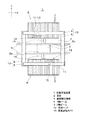
まず図1及び図2を参照して、本発明の一実施の形態における部品実装装置について説明する。部品実装装置1は基板2に部品3(図2)を実装する機能を有し、図示しない通信ネットワークを介して接続される他装置やホストコンピュータとともに部品実装システムを構成する。以下、基板2の搬送方向と平行な方向をX軸方向(第1の方向)、X軸方向と水平面内において直交する方向をY軸方向(第2の方向)、XY平面に対して直交する方向をZ軸方向と定義する。   First, a component mounting apparatus according to an embodiment of the present invention will be described with reference to FIGS. The component mounting apparatus 1 has a function of mounting the component 3 (FIG. 2) on the board 2, and constitutes a component mounting system together with other devices and a host computer connected via a communication network (not shown). Hereinafter, the direction parallel to the transport direction of the substrate 2 is the X-axis direction (first direction), the direction orthogonal to the X-axis direction in the horizontal plane is the Y-axis direction (second direction), and is orthogonal to the XY plane. The direction is defined as the Z-axis direction.

基台4のY軸方向の略中央には、基板搬送機構5が配置されている。基板搬送機構5はX軸方向に並行して延びた一対の搬送レールを備えており、基板2をX軸方向に搬送して所定の作業位置に位置決めする。基板搬送機構5のY軸方向における両側には、それぞれ部品供給部6が配置されている。部品供給部6には、複数のテープフィーダ7がX軸方向に並列して配置されている。テープフィーダ7は、キャリアテープに保持された部品3を間欠送りして、後述する実装ヘッド12による部品取り出し位置まで供給する。   A substrate transport mechanism 5 is disposed in the approximate center of the base 4 in the Y-axis direction. The substrate transport mechanism 5 includes a pair of transport rails extending in parallel with the X-axis direction, and transports the substrate 2 in the X-axis direction and positions it at a predetermined work position. On both sides of the substrate transport mechanism 5 in the Y-axis direction, component supply units 6 are respectively arranged. In the component supply unit 6, a plurality of tape feeders 7 are arranged in parallel in the X-axis direction. The tape feeder 7 intermittently feeds the component 3 held on the carrier tape and supplies it to a component take-out position by a mounting head 12 to be described later.

基台4のX軸方向における両端部には、Y軸方向に延びた長尺のY軸ビーム(第2のビーム)8がそれぞれ設けられている。このY軸ビーム8には、X軸方向に延びた2基のX軸ビーム(第1のビーム)9がY軸方向に移動自在に架設されている。2基のX軸ビーム9にはX方向に移動自在なL字状のヘッド取り付け部材11がそれぞれ装着されており、ヘッド取り付け部材11には実装ヘッド12が取り付けられている。Y軸ビーム8はX軸ビーム9をY方向に移動させ、また、X軸ビーム9は実装ヘッド12をヘッド取り付け部材11とともにX軸方向に移動させる。Y軸ビーム8とX軸ビーム9は、実装ヘッド12を水平方向に移動させるヘッド移動機構10を構成する。   A long Y-axis beam (second beam) 8 extending in the Y-axis direction is provided at both ends in the X-axis direction of the base 4. Two Y-axis beams (first beams) 9 extending in the X-axis direction are installed on the Y-axis beam 8 so as to be movable in the Y-axis direction. An L-shaped head mounting member 11 that is movable in the X direction is mounted on each of the two X-axis beams 9, and a mounting head 12 is mounted on the head mounting member 11. The Y-axis beam 8 moves the X-axis beam 9 in the Y direction, and the X-axis beam 9 moves the mounting head 12 together with the head mounting member 11 in the X-axis direction. The Y-axis beam 8 and the X-axis beam 9 constitute a head moving mechanism 10 that moves the mounting head 12 in the horizontal direction.

実装ヘッド12は複数の単位実装ヘッドから構成される。図2において、単位実装ヘッドの下端部には部品3を吸着可能な吸着ノズル13が装着されている。吸着ノズル13は、実装ヘッド12に内蔵されたノズル昇降機構14(図3)の駆動によってZ軸方向に移動、すなわち昇降する。ヘッド移動機構10とノズル昇降機構14を駆動させることにより、実装ヘッド12はテープフィーダ7により供給される部品3を吸着ノズル13によって吸着して取り出し、所定の作業位置に位置決めされた基板2に部品3を実装する。   The mounting head 12 is composed of a plurality of unit mounting heads. In FIG. 2, a suction nozzle 13 capable of sucking the component 3 is attached to the lower end of the unit mounting head. The suction nozzle 13 moves, that is, moves up and down in the Z-axis direction by driving a nozzle lifting mechanism 14 (FIG. 3) built in the mounting head 12. By driving the head moving mechanism 10 and the nozzle lifting / lowering mechanism 14, the mounting head 12 sucks and takes out the component 3 supplied by the tape feeder 7 by the suction nozzle 13, and puts the component on the substrate 2 positioned at a predetermined work position. 3 is implemented.

図1及び図2において、ヘッド取り付け部材11の下面には、作業位置に位置決めされた基板2側である下方に撮像視野を向けた基板認識カメラ(撮像手段)15が設けられている。基板認識カメラ15は、X軸ビーム9の駆動によって、実装ヘッド12とともに移動自在となっている。基板認識カメラ15は、作業位置に位置決めされた基板2に形成された一対の基板マーク2a(図1)等を撮像する。基板搬送機構5とテープフィーダ7の間には部品認識カメラ16が配設されている。テープフィーダ7により供給された部品3を取り出した実装ヘッド12が部品認識カメラ16の上方に移動することで、部品認識カメラ16は吸着ノズル13に吸着された部品3を下方から撮像する。基板2と部品3の撮像データは、部品実装時に実装ヘッド12の位置を補正する際に用いられる。   1 and 2, a substrate recognition camera (imaging means) 15 is provided on the lower surface of the head mounting member 11 so that the imaging field of view is directed downward on the side of the substrate 2 positioned at the work position. The substrate recognition camera 15 is movable with the mounting head 12 by driving the X-axis beam 9. The substrate recognition camera 15 images a pair of substrate marks 2a (FIG. 1) formed on the substrate 2 positioned at the work position. A component recognition camera 16 is disposed between the substrate transport mechanism 5 and the tape feeder 7. When the mounting head 12 that has taken out the component 3 supplied by the tape feeder 7 moves above the component recognition camera 16, the component recognition camera 16 images the component 3 sucked by the suction nozzle 13 from below. The imaging data of the substrate 2 and the component 3 is used when correcting the position of the mounting head 12 during component mounting.

次に図3を参照して、制御系の構成について説明する。部品実装装置1が備える制御部20は、記憶部21、機構駆動部22、認識処理部23、キャリブレーション実行部24を含んで構成される。また、制御部20は、基板搬送機構5、テープフィーダ7、ヘッド移動機構10、実装ヘッド12、ノズル昇降機構14、基板認識カメラ15、部品認識カメラ16等と接続されている。   Next, the configuration of the control system will be described with reference to FIG. The control unit 20 included in the component mounting apparatus 1 includes a storage unit 21, a mechanism drive unit 22, a recognition processing unit 23, and a calibration execution unit 24. The control unit 20 is connected to the substrate transport mechanism 5, the tape feeder 7, the head moving mechanism 10, the mounting head 12, the nozzle lifting mechanism 14, the substrate recognition camera 15, the component recognition camera 16, and the like.

記憶部21は、部品3が実装された基板2の生産に必要な生産データ等を記憶する。この生産データには、実装ヘッド12の移動制御に必要な制御データ(制御パラメータ)21aが含まれている。制御データ21aは、X軸ビーム9に沿った実装ヘッド12の移動制御と、Y軸ビーム8に沿ったX軸ビーム9の移動制御を組み合わせたデータである。   The storage unit 21 stores production data and the like necessary for production of the board 2 on which the component 3 is mounted. This production data includes control data (control parameters) 21 a necessary for movement control of the mounting head 12. The control data 21 a is data that combines movement control of the mounting head 12 along the X-axis beam 9 and movement control of the X-axis beam 9 along the Y-axis beam 8.

機構駆動部22は、制御部20によって制御されて、基板搬送機構5、テープフィーダ7、ヘッド移動機構10、実装ヘッド12、ノズル昇降機構14を駆動する。これにより、基板2の搬送動作、部品3の実装動作が実行される。なお、ヘッド移動機構10は、制御データ21aに基づいて駆動され、実装ヘッド12を水平方向に移動させる。これにより、実装ヘッド12はテープフィーダ7から部品3を取り出して、所定の作業位置に位置決めされた基板2に実装する。このように部品実装装置1は、制御データ21aに基づいて実装ヘッド12を移動させることで、実装ヘッド12が保持した部品3を基板2に実装する。   The mechanism driving unit 22 is controlled by the control unit 20 to drive the substrate transport mechanism 5, the tape feeder 7, the head moving mechanism 10, the mounting head 12, and the nozzle lifting / lowering mechanism 14. Thereby, the board | substrate 2 conveyance operation | movement and the mounting operation | movement of the components 3 are performed. The head moving mechanism 10 is driven based on the control data 21a and moves the mounting head 12 in the horizontal direction. Thus, the mounting head 12 takes out the component 3 from the tape feeder 7 and mounts it on the substrate 2 positioned at a predetermined work position. In this way, the component mounting apparatus 1 mounts the component 3 held by the mounting head 12 on the substrate 2 by moving the mounting head 12 based on the control data 21a.

認識処理部23は、基板認識カメラ15、部品認識カメラ16によって取得した撮像データを認識処理することで、作業位置に位置決めされた基板2や実装ヘッド12に保持された部品3を検出する。基板2と部品3の検出結果は、部品3の実装時に実装ヘッド12を基板2に対して位置合わせする際に用いられる。   The recognition processing unit 23 recognizes the imaging data acquired by the substrate recognition camera 15 and the component recognition camera 16 to detect the substrate 2 positioned at the work position and the component 3 held by the mounting head 12. The detection results of the substrate 2 and the component 3 are used when the mounting head 12 is aligned with the substrate 2 when the component 3 is mounted.

キャリブレーション実行部24は、部品実装装置1を構成する各種部材に応じたキャリブレーションを実行し、内部処理機構として実測値取得部24a、第1の算出部24b、第2の算出部24c、ビーム形状導出部24d、校正値演算部24eを含んで構成されている。キャリブレーションとは、部品実装装置1を構成する各種部材の固有のばらつきや取り付け誤差等を是正するための校正作業を指し、設備の製造時、据付時、もしくはメンテナンス時等で実施される。   The calibration execution unit 24 executes calibration according to various members constituting the component mounting apparatus 1, and as an internal processing mechanism, an actual measurement value acquisition unit 24a, a first calculation unit 24b, a second calculation unit 24c, a beam The configuration includes a shape deriving unit 24d and a calibration value calculating unit 24e. Calibration refers to a calibration operation for correcting inherent variations and attachment errors of various members constituting the component mounting apparatus 1, and is performed at the time of manufacturing, installing, or maintaining the equipment.

例えば、Y軸ビーム8とX軸ビーム9は長尺の部材であるため、加工精度や各種部品の組み付けによって、歪みが生じる場合がある。ここで、制御部20が実装ヘッド12を制御する際に把握している実装ヘッド12の位置は、制御データ21a上で規定する位置である。したがって、Y軸ビーム8やX軸ビーム9が歪んでいる場合、制御データ21a上での実装ヘッド12の位置と、機械座標系で示される実装ヘッド12の実際の位置との間で誤差が生じる。そのため部品3の実装を正確に行うためには、当該誤差がキャンセルされるように、制御データ21aの校正(キャリブレーション)を行う必要がある。キャリブレーション実行部24は、Y軸ビーム8やX軸ビーム9の形状に基づいて、制御データ21aの校正値を取得するために必要な演算を行う。   For example, since the Y-axis beam 8 and the X-axis beam 9 are long members, distortion may occur due to processing accuracy and assembly of various parts. Here, the position of the mounting head 12 grasped when the control unit 20 controls the mounting head 12 is a position defined on the control data 21a. Therefore, when the Y-axis beam 8 or the X-axis beam 9 is distorted, an error occurs between the position of the mounting head 12 on the control data 21a and the actual position of the mounting head 12 shown in the machine coordinate system. . Therefore, in order to accurately mount the component 3, it is necessary to calibrate the control data 21a so that the error is canceled. The calibration execution unit 24 performs a calculation necessary for obtaining a calibration value of the control data 21a based on the shape of the Y-axis beam 8 or the X-axis beam 9.

次に図4を参照して、X軸ビーム9の形状と傾きについて詳しく説明する。図4は、所定のy座標ごとに実装ヘッド12をX軸方向に移動させたときの軌跡(曲線R)とその軌跡(曲線R)を一次近似した直線Lのイメージ図である。曲線RはX軸ビーム9とY軸ビーム8との歪みの影響を受けた形状であり、直線Lは曲線Rを一次近似(直線に)しているためY軸ビーム8の歪みのみの影響を受けた形状である。ここで、図4の各曲線Rを直線Lにあわせて重ね合わせると各曲線Rの形状は略一致する。すなわち、X軸ビーム9の形状はY軸ビーム8の歪みの影響を受けていなければ、形状が変化しない傾向にあり、X軸ビーム9の形状はY軸ビーム8の歪みのみの影響を受けた形状(直線L)とX軸ビーム9の歪みのみの影響を受けた形状(各曲線Rを直線Lにあわせて重ね合わせた曲線R)に分離することが出来る。なお、破線で示す直線Lは、対応するX軸ビーム9が作業位置に位置決めされた基板2の上方から外れた位置にあることを示している。ここで、上述した課題を解決するために当該X軸ビーム9を移動する基板認識カメラ15のみを用いて制御データ21aの校正を行う場合、以下の問題点が生じる。X軸ビーム9を移動する実装ヘッド12が基板2に部品3を実装する領域の中には、当該X軸ビーム9を移動する基板認識カメラ15では撮像できない領域が存在し、そのような領域においてはX軸ビーム9の形状を取得することができない。そこで、発明者はこうした状況下、上述した曲線Rと直線Lとの関係性に基づき、X軸ビーム9を移動する基板認識カメラ15で撮像できない領域も含めて制御データ21aのキャリブレーションを行う方法に思い至った。   Next, the shape and inclination of the X-axis beam 9 will be described in detail with reference to FIG. FIG. 4 is an image diagram of a locus (curve R) when the mounting head 12 is moved in the X-axis direction for each predetermined y coordinate and a straight line L obtained by linear approximation of the locus (curve R). The curve R is a shape affected by the distortion of the X-axis beam 9 and the Y-axis beam 8, and the straight line L is a linear approximation of the curve R, so that only the distortion of the Y-axis beam 8 is affected. Received shape. Here, when the curves R in FIG. 4 are overlapped with the straight line L, the shapes of the curves R substantially match. That is, if the shape of the X-axis beam 9 is not affected by the distortion of the Y-axis beam 8, the shape tends not to change, and the shape of the X-axis beam 9 is affected only by the distortion of the Y-axis beam 8. The shape (straight line L) and the shape affected by only the distortion of the X-axis beam 9 (curves R obtained by superimposing the curves R in accordance with the straight lines L) can be separated. A straight line L indicated by a broken line indicates that the corresponding X-axis beam 9 is at a position deviated from above the substrate 2 positioned at the working position. Here, when the control data 21a is calibrated using only the substrate recognition camera 15 that moves the X-axis beam 9 in order to solve the above-described problems, the following problems arise. In the region where the mounting head 12 that moves the X-axis beam 9 mounts the component 3 on the substrate 2, there is a region that cannot be imaged by the substrate recognition camera 15 that moves the X-axis beam 9. Cannot acquire the shape of the X-axis beam 9. Therefore, the inventor calibrates the control data 21a including the region that cannot be imaged by the substrate recognition camera 15 that moves the X-axis beam 9 based on the relationship between the curve R and the straight line L described above. I came up with it.

キャリブレーションを実行して制御データ21aの校正値を取得する際には、図5に示す校正用基板17が用いられる。校正用基板17は、基板搬送機構5によって搬送可能であって、基板2と同様の外径形状を有する板状部材である。校正用基板17の上面には、複数の校正用マークMがX軸方向、Y軸方向にそれぞれピッチpx,pyの格子配列で設けられている。便宜上、基板2の搬送方向(X軸方向)と平行な方向を列方向、列方向と水平面内において直交する方向(Y軸方向)を行方向と定義する。また、図5において紙面左側から順に第1列、第2列・・・第12列と定義し、図5において紙面下側から順に第1行、第2行・・・第6行と定義する。キャリブレーション実行時には、校正用基板17は基板搬送機構5によって所定の位置に搬送し、位置決めされ、その後、基板認識カメラ15によって個々の校正用マークMが順次撮像される。なお、校正用基板17は作業者によって所定の位置に設置されてもよい。また、校正用基板17のサイズは基板搬送機構5で位置決めできる最大サイズが好ましいが、最大サイズでなくても本発明のキャリブレーションを行うことで校正用基板17の外方領域もキャリブレーションすることができる。   When the calibration is executed to obtain the calibration value of the control data 21a, the calibration substrate 17 shown in FIG. 5 is used. The calibration substrate 17 can be transported by the substrate transport mechanism 5 and is a plate-like member having the same outer diameter shape as the substrate 2. On the upper surface of the calibration substrate 17, a plurality of calibration marks M are provided in a lattice arrangement with pitches px and py in the X-axis direction and Y-axis direction, respectively. For convenience, a direction parallel to the transport direction (X-axis direction) of the substrate 2 is defined as a column direction, and a direction (Y-axis direction) orthogonal to the column direction in the horizontal plane is defined as a row direction. Further, in FIG. 5, the first column, the second column,..., The twelfth column are defined in order from the left side of the page, and in FIG. 5, the first row, the second row,. . When calibration is performed, the calibration substrate 17 is transported to a predetermined position and positioned by the substrate transport mechanism 5, and then individual calibration marks M are sequentially imaged by the substrate recognition camera 15. The calibration substrate 17 may be installed at a predetermined position by the operator. Further, the size of the calibration substrate 17 is preferably the maximum size that can be positioned by the substrate transport mechanism 5, but even if it is not the maximum size, the outer region of the calibration substrate 17 can be calibrated by performing the calibration of the present invention. Can do.

実測値取得部24aは、基板認識カメラ15によって撮像した校正用マークMの画像を取得する。第1の算出部24bは、実測値取得部24aが取得した実測値に基づいて、校正用マークMの中心の値と実測値とに生じる誤差である変位量(Δx,Δy)を求める。第2の算出部24cは、第1の算出部24bが算出した変位量Δxと各列の値から行ごとのX軸ビーム9の近似直線の傾きとその切片(以下、傾きm、切片bとする)を算出する。ビーム形状導出部24dは、第1の算出部24bが算出した変位量Δxと各列の値とから行ごとのX軸ビーム9の平均形状を導出する。校正値演算部24eは、変位量Δxの近似直線とX軸ビーム9の平均形状とに基づいて、実装ヘッド12の制御データ21aの校正値を演算する。これら各部の詳細は後述する。   The actual measurement value acquisition unit 24 a acquires an image of the calibration mark M captured by the board recognition camera 15. The first calculation unit 24b obtains a displacement amount (Δx, Δy) that is an error between the center value of the calibration mark M and the actual measurement value based on the actual measurement value acquired by the actual measurement value acquisition unit 24a. The second calculation unit 24c calculates the inclination of the approximate straight line of the X-axis beam 9 for each row and its intercept (hereinafter referred to as the inclination m, intercept b, and the like) from the displacement amount Δx calculated by the first calculation unit 24b and the value of each column. Calculate). The beam shape deriving unit 24d derives the average shape of the X-axis beam 9 for each row from the displacement amount Δx calculated by the first calculating unit 24b and the value of each column. The calibration value calculation unit 24e calculates the calibration value of the control data 21a of the mounting head 12 based on the approximate straight line of the displacement amount Δx and the average shape of the X-axis beam 9. Details of these parts will be described later.

本実施の形態における部品実装装置1は以上のように構成される。次に図6のフローチャートに従って、制御データ21aの校正値を取得するための部品実装装置1のキャリブレーション方法について説明する。オペレータによりキャリブレーションの実行が指示されると、キャリブレーション実行部24は当該操作を検知して、基板搬送機構5を制御する。これにより図7(a)に示すように、基板搬送機構5は校正用基板17を搬送し(矢印a)、所定の作業位置に位置決めする(ST1:校正用基板位置決め工程)。すなわち(ST1)では、複数の校正用マークMが第1の方向(X軸方向)及び第2の方向(Y軸方向)に沿って格子状に設けられた校正用基板17を基板搬送機構5によって位置決めする。   The component mounting apparatus 1 in the present embodiment is configured as described above. Next, a calibration method of the component mounting apparatus 1 for obtaining the calibration value of the control data 21a will be described according to the flowchart of FIG. When the execution of calibration is instructed by the operator, the calibration execution unit 24 detects the operation and controls the substrate transport mechanism 5. Accordingly, as shown in FIG. 7A, the substrate transport mechanism 5 transports the calibration substrate 17 (arrow a) and positions it at a predetermined work position (ST1: calibration substrate positioning step). That is, in (ST1), a plurality of calibration marks M are provided in a lattice shape along the first direction (X-axis direction) and the second direction (Y-axis direction). Position by.

次いで、校正用マークMの位置における実装ヘッド12の実測値を取得するための処理が実行される(ST2:実測値取得工程)。すなわち図7(b)に示すように、実装ヘッド12は制御データ21aに基づいて、所定の作業位置(行と列)に位置決めされた校正用基板17の上方を移動する。このとき、実装ヘッド12は、一体となって移動する基板認識カメラ15の撮像視野の中心が個々の校正用マークMの中心αに移動制御される。これにより、基板認識カメラ15は、複数の校正用マークMを個別に順次撮像する。実測値取得部24aは個々の校正用マークMの中心αを取得する。校正用マークMの撮像順序は任意である。本実施の形態では、図8に示すように、基板認識カメラ15は行ごとにX軸方向に沿って移動しながら(矢印b)、校正用マークMを順次撮像する。   Next, processing for acquiring the actual measurement value of the mounting head 12 at the position of the calibration mark M is executed (ST2: actual measurement value acquisition step). That is, as shown in FIG. 7B, the mounting head 12 moves above the calibration substrate 17 positioned at a predetermined work position (row and column) based on the control data 21a. At this time, the mounting head 12 is controlled to move so that the center of the imaging field of the substrate recognition camera 15 that moves together is the center α of each calibration mark M. As a result, the substrate recognition camera 15 sequentially captures a plurality of calibration marks M individually. The actual measurement value acquisition unit 24a acquires the center α of each calibration mark M. The imaging order of the calibration mark M is arbitrary. In the present embodiment, as shown in FIG. 8, the substrate recognition camera 15 sequentially images the calibration mark M while moving along the X-axis direction for each row (arrow b).

図9は、基板認識カメラ15が所定の校正用マークMの上方まで移動したときの撮像視野15aを例示したものである。Y軸ビーム8やX軸ビーム9に歪みが生じているとき、撮像視野15aの中心βと校正用マークMの中心αとには誤差が生じる。第1の算出部24bは、この誤差を変位量(Δx,Δy)として算出する(ST3:第1の算出工程)。   FIG. 9 illustrates the imaging field 15a when the substrate recognition camera 15 moves above a predetermined calibration mark M. FIG. When the Y-axis beam 8 or the X-axis beam 9 is distorted, an error occurs between the center β of the imaging field 15a and the center α of the calibration mark M. The first calculation unit 24b calculates this error as a displacement amount (Δx, Δy) (ST3: first calculation step).

次いで、第2の算出部24cは、第1の算出部24bが算出した行ごとの変位量Δxと各列の値とで形成される曲線を一時近似することで得られる近似直線から傾きmと切片bを算出する(ST4:第2の算出工程)。傾きmと切片bは、図10に示すように、校正用基板17の面内において校正用マークMが設けられた領域である面内領域E1を対象として算出される。また、面内領域E1よりも外方(X軸ビーム9の長手方向と直交するY軸方向)に設定された領域である面外領域E2を含む領域での傾きmと切片bは推定値が算出される。なお、複数の基板を並列に搬送する構成の場合は、一対の搬送レーンごとに校正用基板17を用いて傾きmと切片bが算出される。すなわち、この場合における面外領域E2は複数の校正用基板17の間にも存在する。   Next, the second calculation unit 24c calculates the slope m from the approximate straight line obtained by temporarily approximating the curve formed by the displacement amount Δx for each row calculated by the first calculation unit 24b and the value of each column. The intercept b is calculated (ST4: second calculation step). As shown in FIG. 10, the inclination m and the intercept b are calculated with respect to an in-plane region E1, which is a region where the calibration mark M is provided in the plane of the calibration substrate 17. Further, the inclination m and the intercept b in the region including the out-of-plane region E2, which is a region set outside (in the Y-axis direction orthogonal to the longitudinal direction of the X-axis beam 9) from the in-plane region E1, are estimated values. Calculated. In the case of a configuration in which a plurality of substrates are transported in parallel, the inclination m and the intercept b are calculated using the calibration substrate 17 for each pair of transport lanes. That is, the out-of-plane region E2 in this case also exists between the plurality of calibration substrates 17.

ここで、第2の算出部24cが算出する近似直線の算出方法の一例を示す。まず図11に示すように、第2の算出部24cは、第1の算出部24bが算出した所定の行(同図では第1行)の個々の撮像視野15aの中心β(β1,β2,・・・β12)と個々の校正用マークMの中心α(α1,α2・・・α12)との誤差である各変位量Δx1,Δx2・・・Δx12と各列の値を用いて近似直線を算出する。算出方法としては、全ての変位量を用いて近似直線を算出してもよいし、簡易な算出方法としてΔx1とΔx12の左右両端だけで近似直線を算出してもよい。そして、第2の算出部24cは、当該近似直線から傾きmと切片bを算出する。第2の算出部24cは、第2行、第3行・・・第6行に対応する近似直線の傾きmと切片bも同様の方法で算出する。   Here, an example of an approximate straight line calculation method calculated by the second calculation unit 24c will be described. First, as shown in FIG. 11, the second calculation unit 24 c is configured such that the center β (β1, β2, β2) of each imaging field of view 15 a in a predetermined row (first row in the figure) calculated by the first calculation unit 24 b. ... Β12) and the displacements Δx1, Δx2... Δx12, which are errors between the center α of each calibration mark M (α1, α2. calculate. As a calculation method, an approximate straight line may be calculated using all the displacement amounts, or as a simple calculation method, an approximate straight line may be calculated only at both right and left ends of Δx1 and Δx12. Then, the second calculation unit 24c calculates the slope m and the intercept b from the approximate straight line. The second calculation unit 24c calculates the slope m and the intercept b of the approximate line corresponding to the second row, the third row,.

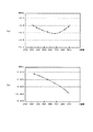
第2の算出部24cは、さらに行ごとに算出した傾きmと切片bに基づいて、面外領域E2における傾きmと切片bの推定値を算出する。先ず、面内領域E1における傾きmのn次近似式と切片bのn次近似式を算出する。図12(a)は、行ごとに求めた傾きmの分布を示す図であり、横軸に各行の値、縦軸に傾きmをとっている。第2の算出部24cは、傾きmの分布からいわゆる内挿法(補間法)により面内領域E1における行と傾きmの相関を表すn次近似式を求める(図12(a)で示す実線の曲線を参照)。また、図12(b)は、行ごとに求めた切片bの分布を示す図であり、横軸に各行の値、縦軸に切片bをとっている。第2の算出部24cは、切片bの分布から同じく内挿法により面内領域E1における行と切片bの相関を表すn次近似式を求める(図12(b)で示す実線の曲線を参照)。   The second calculation unit 24c further calculates an estimated value of the slope m and the intercept b in the out-of-plane region E2 based on the slope m and the intercept b calculated for each row. First, an n-order approximate expression of the slope m and an n-order approximate expression of the intercept b in the in-plane region E1 are calculated. FIG. 12A is a diagram showing the distribution of the slope m obtained for each row, with the horizontal axis representing the value of each row and the vertical axis representing the slope m. The second calculation unit 24c obtains an nth-order approximation expression representing the correlation between the row and the inclination m in the in-plane region E1 from the distribution of the inclination m by a so-called interpolation method (interpolation method) (solid line shown in FIG. 12A). See the curve). FIG. 12B is a diagram showing the distribution of the intercept b obtained for each row, with the horizontal axis representing the value of each row and the vertical axis representing the intercept b. The second calculation unit 24c obtains an nth-order approximate expression representing the correlation between the row and the intercept b in the in-plane region E1 from the distribution of the intercept b by the same interpolation method (see the solid curve shown in FIG. 12B). ).

次いで、面外領域E2における傾きmと切片bの推定値を算出する。すなわち、第2の算出部24cは、図12(a)で示す面内領域E1における行と傾きmの相関を表すn次近似式に基づいて、いわゆる外挿法(補間法)により面外領域E2の行における傾きmを求める(図12(a)で示す破線の曲線を参照)。また、第2の算出部24cは、図12(b)で示す面内領域E1における各行の値と切片bの相関を表すn次近似式に基づいて、外挿法により面外領域E2の行における切片bを求める(図12(b)で示す破線の曲線を参照)。第2の算出部24cは、面内領域E1における行と傾きmの相関を表すn次近似式から面外領域E2の行における傾きmを推定し、面内領域E1における行と切片bの相関を表すn次近似式から面外領域E2の行における切片bを推定する。これにより、第2の算出部24cからは面外領域E2の行における傾きmと切片bから形成される直線、すなわち、面外領域E2を含めたY軸ビーム8の歪みのみの影響を受けたX軸ビーム9の形状が得られる。このように(ST4)において、第2の算出部24cは変位量Δxとその行の値に基づいて、X軸ビーム9の形状を一次近似した近似直線の傾きmと切片bを、面外領域E2を含めて各行(Y軸ビーム8に対するX軸ビーム9の位置)ごとに算出する。なお、上述の面外領域E2における傾きmと切片bの推定値の算出方法は例示であって、その他にも例えば面外領域E2に隣接する面内領域E1の複数の値の変化量から推定値を算出してもよい。   Next, estimated values of the slope m and the intercept b in the out-of-plane region E2 are calculated. That is, the second calculation unit 24c performs an out-of-plane region by a so-called extrapolation method (interpolation method) based on an nth-order approximation expression that represents the correlation between the row and the slope m in the in-plane region E1 illustrated in FIG. The slope m in the row E2 is obtained (see the dashed curve shown in FIG. 12A). Further, the second calculation unit 24c uses the extrapolation method to calculate the row of the out-of-plane region E2 based on the nth-order approximation expression that represents the correlation between the value of each row in the in-plane region E1 and the intercept b in FIG. Is obtained (see the dashed curve shown in FIG. 12B). The second calculation unit 24c estimates the slope m in the row in the out-of-plane region E2 from the n-th order approximation expression representing the correlation between the row in the in-plane region E1 and the slope m, and correlates the row and the intercept b in the in-plane region E1. The intercept b in the row of the out-of-plane region E2 is estimated from the n-th order approximation formula representing Thereby, the second calculation unit 24c was affected only by the straight line formed from the slope m and the intercept b in the row of the out-of-plane region E2, that is, the distortion of the Y-axis beam 8 including the out-of-plane region E2. The shape of the X-axis beam 9 is obtained. As described above, in (ST4), the second calculation unit 24c calculates the inclination m and the intercept b of the approximate straight line obtained by linearly approximating the shape of the X-axis beam 9 based on the displacement amount Δx and the value of the row. The calculation is performed for each row (the position of the X-axis beam 9 with respect to the Y-axis beam 8) including E2. Note that the above-described method for calculating the estimated values of the slope m and the intercept b in the out-of-plane region E2 is merely an example. A value may be calculated.

次いで、ビーム形状導出部24dは面外領域E2を含めたX軸ビーム9の形状を導出する(ST5:ビーム形状導出工程)。面外領域E2を含めたX軸ビーム9の形状は、第1の算出部24bが算出した行ごとの変位量Δxと各列の値で形成される曲線から第2の算出部24cで算出した近似直線を差し引くことで導出することができる。図13(a)は、所定行における変位量Δxと各列の値との関係を示す図である。図13(b)は、所定行における算出した差分量と各列の値との関係を示す図である。まず、所定の行(ここでは第1行)における変位量Δxと各列の値で形成される曲線の形状を導出する。図13(a)において、ビーム形状導出部24dは、第2の算出部24cで算出した近似直線における各列の変位量Δxと、第1の算出部24bで算出した第1行の各列の変位量Δxとの差分量を算出する。算出した差分量と列の値との関係を図13(b)に示す。図13(b)に示すように、算出した差分量と列の値との関係は、第2の算出部24cで算出した近似直線の傾きmと切片bの影響が取り除かれた状態になっており、この差分量で形成される形状は面内領域E1の第1行におけるY軸ビーム8の歪みのみの影響を受けていないX軸ビーム9の形状である。言い換えれば、X軸ビーム9の歪みの影響のみを受けたX軸ビーム9の形状である。次に同様の算出を他の行に対しても導出し、全ての行に対してX軸ビーム9の形状を導出した後、列ごとに算出した差分量の平均値を算出する。これが、面内領域E1のX軸ビーム9の歪みの影響を受けたX軸ビーム9の形状の基準となる。さらに、この基準のX軸ビーム9の形状はY軸ビーム8の歪みの影響を受けていないため、面外領域E2においても同じ形状が適用できる。   Next, the beam shape deriving unit 24d derives the shape of the X-axis beam 9 including the out-of-plane region E2 (ST5: beam shape deriving step). The shape of the X-axis beam 9 including the out-of-plane region E2 was calculated by the second calculation unit 24c from the curve formed by the displacement amount Δx for each row calculated by the first calculation unit 24b and the value of each column. It can be derived by subtracting the approximate line. FIG. 13A is a diagram illustrating the relationship between the displacement amount Δx in a predetermined row and the value of each column. FIG. 13B is a diagram illustrating a relationship between the calculated difference amount in a predetermined row and the value of each column. First, the shape of a curve formed by the displacement amount Δx and the value of each column in a predetermined row (here, the first row) is derived. In FIG. 13A, the beam shape deriving unit 24d includes the displacement amount Δx of each column in the approximate straight line calculated by the second calculating unit 24c and the column of the first row calculated by the first calculating unit 24b. A difference amount from the displacement amount Δx is calculated. FIG. 13B shows the relationship between the calculated difference amount and the column value. As shown in FIG. 13B, the relationship between the calculated difference amount and the column value is in a state in which the influence of the inclination m of the approximate straight line calculated by the second calculation unit 24c and the intercept b is removed. The shape formed by this difference amount is the shape of the X-axis beam 9 that is not affected by only the distortion of the Y-axis beam 8 in the first row of the in-plane region E1. In other words, the shape of the X-axis beam 9 is only affected by the distortion of the X-axis beam 9. Next, the same calculation is derived for other rows, and the shape of the X-axis beam 9 is derived for all rows, and then the average value of the difference amounts calculated for each column is calculated. This is a reference for the shape of the X-axis beam 9 affected by the distortion of the X-axis beam 9 in the in-plane region E1. Further, since the shape of the reference X-axis beam 9 is not affected by the distortion of the Y-axis beam 8, the same shape can be applied to the out-of-plane region E2.

次いで、ビーム形状導出部24dは、第2の算出工程(ST4)で算出された面外領域E2の傾きmと切片bの一次直線の変位量Δxとビーム形状導出工程(ST5)で導出されたX軸ビーム9の基準の形状の変位量Δxとを列ごとに合成することで、面外領域E2の行ごとの変位量Δxが算出される。校正値演算部24eはこの変位量を各座標点において相殺する値を演算し、その演算した値が校正値となる(ST6:校正値演算工程)。以上の工程(ST1)〜(ST5)は、変位量Δyでも実行され、さらに個々のX軸ビーム9ごとに実行される。   Next, the beam shape deriving unit 24d is derived in the slope m of the out-of-plane region E2 calculated in the second calculation step (ST4), the displacement amount Δx of the primary straight line of the intercept b, and the beam shape deriving step (ST5). By combining the displacement amount Δx of the reference shape of the X-axis beam 9 for each column, the displacement amount Δx for each row of the out-of-plane region E2 is calculated. The calibration value calculation unit 24e calculates a value that cancels out this displacement amount at each coordinate point, and the calculated value becomes a calibration value (ST6: calibration value calculation step). The above steps (ST1) to (ST5) are also executed for the displacement amount Δy, and further executed for each individual X-axis beam 9.

制御データ21aの校正値を演算したならば、その後、基板2に部品3を実装する実装動作が実行される。すなわち、実装ヘッド12は、テープフィーダ7によって供給された部品3を取り出し、所定の作業位置に位置決めされた基板2に実装する。この実装動作においては、制御データ21aの校正値に基づいて実装ヘッド12の移動制御がなされる。これにより、Y軸ビーム8やX軸ビーム9に歪み等が生じている場合でも、基板2に実装されるべき位置に部品3を精度良く実装することができる。   If the calibration value of the control data 21a is calculated, then a mounting operation for mounting the component 3 on the board 2 is executed. That is, the mounting head 12 takes out the component 3 supplied by the tape feeder 7 and mounts it on the substrate 2 positioned at a predetermined work position. In this mounting operation, movement control of the mounting head 12 is performed based on the calibration value of the control data 21a. As a result, even when the Y-axis beam 8 and the X-axis beam 9 are distorted, the component 3 can be accurately mounted at the position where it should be mounted on the substrate 2.

以上説明したように、本実施の形態によれば、校正用基板17の校正用マークMが設けられた面内領域E1のみならず、面内領域E1の外方に設定された面外領域E2に対応する実装ヘッド12の制御データ21aを正確に校正することができる。また、複数のX軸ビーム9にそれぞれ設けられた基板認識カメラ15を使用する必要がないため、信頼性の高い校正値を取得することができる。   As described above, according to the present embodiment, not only the in-plane region E1 provided with the calibration mark M of the calibration substrate 17, but also the out-of-plane region E2 set outside the in-plane region E1. It is possible to accurately calibrate the control data 21a of the mounting head 12 corresponding to the above. In addition, since it is not necessary to use the substrate recognition camera 15 provided for each of the plurality of X-axis beams 9, a highly reliable calibration value can be acquired.

上述したキャリブレーション方法によって取得可能な実装ヘッド12の制御データ21aの校正値は、図10に示すように、X軸ビーム9の形状が導出される面内領域E1及び面外領域E2の幅Wに限られる。以下に説明するその他のキャリブレーション方法は、図14に示すように、面内領域E1及び面外領域E2の幅WからさらにX軸ビーム9の長手方向(X軸方向)に拡張した領域に設定された面外領域E3における実装ヘッド12の制御データ21aの校正値を取得することができる。   As shown in FIG. 10, the calibration value of the control data 21a of the mounting head 12 that can be obtained by the above-described calibration method is the width W of the in-plane region E1 and the out-of-plane region E2 from which the shape of the X-axis beam 9 is derived. Limited to. In the other calibration methods described below, as shown in FIG. 14, an area that is further extended in the longitudinal direction (X-axis direction) of the X-axis beam 9 from the width W of the in-plane area E1 and the out-of-plane area E2 is set. The calibration value of the control data 21a of the mounting head 12 in the out-of-plane region E3 can be acquired.

以下、その他のキャリブレーション方法について説明するが、既に説明した工程と重複する工程については簡略する。まず、基板搬送機構5は校正用基板17を搬送し、所定の作業位置に位置決めする(ST11:基板搬送工程)。次いで、実測値取得部24aは基板認識カメラ15によって撮像した校正用マークMの撮像を取得する(ST12:実測値取得工程)。そして、第1の算出部24bは、実測値取得部24aが取得した実測値に基づいて、変位量(Δx,Δy)を算出する(ST13:第1の算出工程)。第2の算出部24cは、第1の算出部24bが算出した所定行の各変位量Δxを用いて算出された近似直線の傾きmと切片bを所定行ごとに算出する(ST14:第2の算出工程)。   Hereinafter, other calibration methods will be described, but the steps that are already described will be simplified. First, the substrate transport mechanism 5 transports the calibration substrate 17 and positions it at a predetermined work position (ST11: substrate transport process). Next, the actual measurement value acquisition unit 24a acquires an image of the calibration mark M captured by the board recognition camera 15 (ST12: actual measurement value acquisition step). And the 1st calculation part 24b calculates displacement amount ((DELTA) x, (DELTA) y) based on the actual value acquired by the actual value acquisition part 24a (ST13: 1st calculation process). The second calculation unit 24c calculates the slope m and the intercept b of the approximate straight line calculated using each displacement amount Δx of the predetermined row calculated by the first calculation unit 24b for each predetermined row (ST14: second). Calculation step).

次いで、ビーム形状導出部24dはX軸ビーム9の形状を導出する(ST15)。ここでは、面内領域E1のみならず、面外領域E3におけるX軸ビーム9の形状も導出される。面内領域E1においてX軸ビーム9の形状を導出する具体的な方法は前述のとおりであるため説明を省略する。   Next, the beam shape deriving unit 24d derives the shape of the X-axis beam 9 (ST15). Here, not only the in-plane region E1 but also the shape of the X-axis beam 9 in the out-of-plane region E3 is derived. Since the specific method for deriving the shape of the X-axis beam 9 in the in-plane region E1 is as described above, the description thereof is omitted.

面外領域E3に対応するX軸ビーム9の形状を導出する方法について説明する。ここでは、図14で示す紙面左側の面外領域E3に対応するX軸ビーム9の形状を導出する場合について説明する。面外領域E3に対応するX軸ビーム9の形状は、面内領域E1において導出したY軸ビーム8の歪みのみの影響を受けていないX軸ビーム9の形状から推定する。図15(a)は、変位量Δx(平均値)の分布をx座標ごとに示す図であり、横軸にx座標、縦軸に変位量Δxをとっている。ビーム形状導出部24dは当該図から、第1列の変位量Δx(平均値)を示すデータ点P1と、第1列に隣接する第2列の変位量Δx(平均値)を示すデータ点P2との間の変化量(P1−P2)を求める。そして、ビーム形状導出部24dはデータ点P1が示す変位量Δxに変化量を加算することで、データ点P1に隣接し、面外領域E3に位置するデータ点P0を求める(PO=P1+(P1−P2))。   A method for deriving the shape of the X-axis beam 9 corresponding to the out-of-plane region E3 will be described. Here, a case will be described in which the shape of the X-axis beam 9 corresponding to the out-of-plane region E3 on the left side in FIG. 14 is derived. The shape of the X-axis beam 9 corresponding to the out-of-plane region E3 is estimated from the shape of the X-axis beam 9 that is not affected by only the distortion of the Y-axis beam 8 derived in the in-plane region E1. FIG. 15A is a diagram showing the distribution of the displacement amount Δx (average value) for each x coordinate. The horizontal axis represents the x coordinate, and the vertical axis represents the displacement amount Δx. From the figure, the beam shape deriving unit 24d shows the data point P1 indicating the displacement amount Δx (average value) in the first row and the data point P2 indicating the displacement amount Δx (average value) in the second row adjacent to the first row. The amount of change between (P1-P2) is obtained. The beam shape deriving unit 24d adds the change amount to the displacement amount Δx indicated by the data point P1, thereby obtaining the data point P0 adjacent to the data point P1 and located in the out-of-plane region E3 (PO = P1 + (P1 -P2)).

図14で示す紙面右側の面外領域E3におけるデータ点も同様の方法で導出する。そして、ビーム形状導出部24dは、第2の算出工程(ST14)で算出された近似直線の変位量Δxとビーム形状導出工程(ST15)で導出された面外領域E3を含んだX軸ビーム9の平均形状の変位量Δxとを列ごとに合成することで、面外領域E3を含んだ行ごとの変位量Δxが算出される。以上のとおり、ビーム形状導出部24dは、面内領域E1の幅WからさらにX軸ビーム9の長手方向に延びて設定された面外領域E3を含めたX軸ビーム9の形状を導出することができる。   Data points in the out-of-plane region E3 on the right side of the page shown in FIG. 14 are derived by the same method. Then, the beam shape deriving unit 24d includes the X-axis beam 9 including the approximate straight line displacement Δx calculated in the second calculation step (ST14) and the out-of-plane region E3 derived in the beam shape deriving step (ST15). The displacement amount Δx for each row including the out-of-plane region E3 is calculated by combining the average shape displacement amount Δx for each column. As described above, the beam shape deriving unit 24d derives the shape of the X-axis beam 9 including the out-of-plane region E3 set by extending in the longitudinal direction of the X-axis beam 9 from the width W of the in-plane region E1. Can do.

校正値演算部24eは、この変位量Δxを各座標点において相殺する値を演算し、その演算した値が校正値となる。   The calibration value calculator 24e calculates a value that cancels out the displacement Δx at each coordinate point, and the calculated value becomes the calibration value.

本発明の部品実装装置のキャリブレーション方法及び部品実装装置は本実施の形態に限定されず、発明の趣旨を変更しない範囲で変更することができる。例えば、X軸ビーム9の形状は、一つの行に属する実測値のみに基づいて導出してもよい。X軸ビーム9の形状は、Y軸方向に移動しても殆ど変わらないと考えられるためである。なお、行ごとにおけるX軸ビーム9の傾きm、切片bは、校正用基板17上の両端に位置する校正用マークMに対する実装ヘッド12の機械座標系の位置βnに基づいて求める。   The component mounting apparatus calibration method and the component mounting apparatus according to the present invention are not limited to the present embodiment, and can be changed without changing the gist of the invention. For example, the shape of the X-axis beam 9 may be derived based only on actually measured values belonging to one row. This is because the shape of the X-axis beam 9 is considered to be almost unchanged even when moved in the Y-axis direction. The inclination m and the intercept b of the X-axis beam 9 for each row are obtained based on the machine coordinate system position βn of the mounting head 12 with respect to the calibration marks M located at both ends on the calibration substrate 17.

図16を例示して説明すると、基板認識カメラ15は第1行に属する全ての校正用マークM1,M2・・・M12を順次撮像し、その一方で第2行、第3行・・・第6行については、基板認識カメラ15は両端に位置する校正用マークM13,M24,M25,M36,M37,M48,M49,M60,M61,M72のみを撮像する。X軸ビーム9の形状は、校正用マークM1,M2・・・M12の実測値、すなわち機械座標系の位置β1,β2・・・β12から導出する。また、X軸ビーム9の傾きmと切片bは、各行の両端に位置する校正用マークMに対応する実測値(機械座標系の位置β13,β24,β25,β36,β37,β48,β49,β60,β61,β72)に基づいて算出する。   Referring to FIG. 16, the board recognition camera 15 sequentially images all the calibration marks M1, M2,... M12 belonging to the first row, while the second row, the third row,. For six rows, the substrate recognition camera 15 images only the calibration marks M13, M24, M25, M36, M37, M48, M49, M60, M61, and M72 located at both ends. The shape of the X-axis beam 9 is derived from the actually measured values of the calibration marks M1, M2,... M12, that is, the positions β1, β2,. Further, the inclination m and intercept b of the X-axis beam 9 are measured values corresponding to the calibration marks M located at both ends of each row (machine coordinate system positions β13, β24, β25, β36, β37, β48, β49, β60). , Β61, β72).

すなわち、実測値取得工程(ST2(12))において、Y軸方向(第2の方向)における少なくとも一つのy座標が共通する複数の校正用マークMを基板認識カメラ15によって順次撮像することで、実装ヘッド12の位置の実測値を取得し、ビーム形状導出工程(ST5(15))において、一つのy座標が共通する複数の校正用マークMを撮像して取得した実測値に基づいて、第1のビームの形状を導出するようにしてもよい。これによれば、校正用マークMの撮像数を減らしてキャリブレーションに要する時間を短縮させることができる。   That is, in the actual measurement value acquisition step (ST2 (12)), the substrate recognition camera 15 sequentially images a plurality of calibration marks M having at least one y coordinate in the Y-axis direction (second direction). An actual measurement value of the position of the mounting head 12 is acquired, and in the beam shape deriving step (ST5 (15)), based on the actual measurement value acquired by imaging a plurality of calibration marks M having a common y coordinate. The shape of one beam may be derived. According to this, it is possible to reduce the number of times the calibration mark M is captured and to shorten the time required for calibration.

また、実測値のデータを取得した後、以下に示す工程を新たに加えてもよい。すなわち図17(a)に示すように、制御部20は、個々の校正用マークMに対応する実装ヘッド12の機械座標系の位置βnに基づいてn次近似式を求めることにより、X軸ビーム9の形状を行ごとに導出する。図17(a)では、X軸ビーム9の形状を行ごとに曲線R1,R2・・・R6で表している。そして、制御部20は、X軸ビーム9の傾きmがキャンセルされるようにn次近似式から求められる実装ヘッド12の機械座標系の位置βnを座標変換したうえで、図17(b)に示すように、複数のX軸ビーム9の形状(曲線R1〜R6)を重ね合わせる。そして、制御部20は、X軸ビーム9の形状を重ね合わせた状態において、一定値以上離れた実装ヘッド12の機械座標系の位置Sn*があるか否かを判断する。このような実装ヘッド12の機械座標系の位置Sn*が発生する要因としては、校正用基板17上に付着した埃を校正用マークMと誤って制御部20が認識したような場合が挙げられる。この場合、制御部20は当該位置Sn*に対応する校正用マークMの撮像をやり直す等の措置をとる。若しくは、制御部20は、当該位置Sn*に対応する校正用マークMに属する列の変位量Δx,Δyの平均値に基づいて、実装ヘッド12の位置の実測値のデータを修正する。これにより、制御データ21aの校正値をより正確に演算して、実装精度を向上させることができる。   Moreover, after acquiring the data of actual measurement values, the following steps may be newly added. That is, as shown in FIG. 17A, the control unit 20 obtains an n-order approximate expression based on the position βn of the machine coordinate system of the mounting head 12 corresponding to each calibration mark M, thereby obtaining an X-axis beam. 9 shapes are derived for each row. In FIG. 17A, the shape of the X-axis beam 9 is represented by curves R1, R2,... R6 for each row. Then, the control unit 20 performs coordinate conversion on the position βn of the mechanical coordinate system of the mounting head 12 obtained from the nth-order approximation so that the inclination m of the X-axis beam 9 is canceled, and then in FIG. As shown, the shapes of the plurality of X-axis beams 9 (curves R1 to R6) are overlapped. Then, the control unit 20 determines whether or not there is a position Sn * in the machine coordinate system of the mounting head 12 that is separated by a certain value or more in a state where the shapes of the X-axis beams 9 are superimposed. The cause of the position Sn * of the mounting coordinate system 12 of the mounting head 12 includes a case where the control unit 20 mistakenly recognizes dust adhering to the calibration substrate 17 as the calibration mark M. . In this case, the control unit 20 takes measures such as re-imaging the calibration mark M corresponding to the position Sn *. Alternatively, the control unit 20 corrects the data of the actual measurement value of the position of the mounting head 12 based on the average value of the displacement amounts Δx and Δy of the column belonging to the calibration mark M corresponding to the position Sn *. Thereby, the calibration value of the control data 21a can be calculated more accurately, and the mounting accuracy can be improved.

本発明によれば、制御データを正確に校正することができ、部品実装分野において特に有用である。   According to the present invention, control data can be accurately calibrated, which is particularly useful in the field of component mounting.

1 部品実装装置
2 基板
3 部品
5 基板搬送機構
8 Y軸ビーム(第2のビーム)
9 X軸ビーム(第1のビーム)
12 実装ヘッド
15 基板認識カメラ
24a 実測値取得部
24b 第1の算出部
24c 第2の算出部
24d ビーム形状導出部
24e 校正値演算部
DESCRIPTION OF SYMBOLS 1 Component mounting apparatus 2 Board | substrate 3 Components 5 Board | substrate conveyance mechanism 8 Y-axis beam (2nd beam)
9 X-axis beam (first beam)
DESCRIPTION OF SYMBOLS 12 Mounting head 15 Board | substrate recognition camera 24a Actual value acquisition part 24b 1st calculation part 24c 2nd calculation part 24d Beam shape derivation | leading-out part 24e Calibration value calculation part

Claims (6)

作業位置に位置決めされた基板に部品を実装する実装ヘッドと、基板の搬送方向と平行な第1の方向に延び前記実装ヘッドを前記第1の方向に移動させる第1のビームと、前記第1の方向と水平面内で直交する第2の方向に延び前記第1のビームを前記第2の方向に移動させる第2のビームと、前記作業位置に位置決めされた基板を撮像し前記実装ヘッドとともに移動する撮像手段と、を備えた部品実装装置において、
前記第1のビームに沿った前記実装ヘッドの移動制御と前記第2のビームに沿った前記第1のビームの移動制御を組み合わせた制御データを校正する制御データのキャリブレーション方法であって、
校正用基板の前記第1の方向及び第2の方向に沿って設けられた複数の校正用マークを順次撮像して得られる実測値に基づいて、校正用マークの中心と実測値とに生じる誤差である変位量を算出する第1の算出工程と、
前記第1の算出工程で算出した変位量に基づいて、前記校正用基板の面内の領域である面内領域と、前記面内領域よりも外方に設定された領域である面外領域における傾きと切片を算出する第2の算出工程と、
前記第1の算出工程で算出した算出した変位量から形成される形状と前記第2の算出工程で算出した傾きと切片で形成される前記変位量の近似直線とに基づいて、前記第1のビームの形状を導出するビーム形状導出工程と、
前記ビーム形状導出工程において導出した前記第1のビームの形状に基づいて、前記面内領域と、前記面外領域を含めた領域における前記実装ヘッドの制御データの校正値を演算する校正値演算工程と、を含む制御データのキャリブレーション方法。
A mounting head for mounting a component on a substrate positioned at a work position; a first beam extending in a first direction parallel to a substrate transport direction; and moving the mounting head in the first direction; The second beam extending in a second direction orthogonal to the direction of the first direction and moving the first beam in the second direction and the substrate positioned at the working position are imaged and moved together with the mounting head In a component mounting apparatus comprising an imaging means for
A control data calibration method for calibrating control data combining movement control of the mounting head along the first beam and movement control of the first beam along the second beam,
An error occurring between the center of the calibration mark and the actual measurement value based on the actual measurement value obtained by sequentially imaging the plurality of calibration marks provided along the first direction and the second direction of the calibration substrate. A first calculation step of calculating a displacement amount,
Based on the amount of displacement calculated in the first calculation step, in an in-plane area that is an in-plane area of the calibration substrate and an out-of-plane area that is an area set outside the in-plane area. A second calculation step for calculating the slope and intercept;
Based on the shape formed from the calculated displacement calculated in the first calculation step, the slope calculated in the second calculation step, and the approximate straight line of the displacement formed by the intercept, the first A beam shape deriving step for deriving a beam shape;
Calibration value calculation step for calculating a calibration value of control data of the mounting head in the region including the in-plane region and the out-of-plane region based on the shape of the first beam derived in the beam shape deriving step. And a control data calibration method including:
前記ビーム形状導出工程において、前記面内領域に対応する範囲における前記第1のビームの形状に加え、前記面外領域に対応する範囲における前記第1のビームの形状を前記実測値に基づいて導出する、請求項1に記載の制御データのキャリブレーション方法。   In the beam shape deriving step, in addition to the shape of the first beam in the range corresponding to the in-plane region, the shape of the first beam in the range corresponding to the out-of-plane region is derived based on the actually measured value. The control data calibration method according to claim 1. 前記第1の算出工程において、前記第2の方向における少なくとも一つの座標が共通する複数の前記校正用マークを前記撮像手段によって順次撮像することで、前記実装ヘッドの位置の実測値を取得し、
前記ビーム形状導出工程において、前記一つの座標が共通する複数の前記校正用マークを撮像して取得した前記実測値に基づいて、前記第1のビームの形状を導出する、請求項1又は2に記載の制御データのキャリブレーション方法。
In the first calculation step, by sequentially imaging the plurality of calibration marks having at least one coordinate in the second direction by the imaging unit, an actual measurement value of the position of the mounting head is obtained,
3. The shape of the first beam is derived in the beam shape deriving step based on the actual measurement values obtained by imaging the plurality of calibration marks having the same one coordinate. The calibration method of the control data as described.
作業位置に位置決めされた基板に部品を実装する実装ヘッドと、基板の搬送方向と平行な第1の方向に延び前記実装ヘッドを前記第1の方向に移動させる第1のビームと、前記第1の方向と水平面内で直交する第2の方向に延び前記第1のビームを前記第2の方向に移動させる第2のビームと、前記作業位置に位置決めされた基板側に撮像視野を向け前記実装ヘッドとともに移動自在な撮像手段と、を備え、前記第1のビームに沿った前記実装ヘッドの移動制御と前記第2のビームに沿った前記第1のビームの移動制御を組み合わせた制御データに基づいて前記実装ヘッドを移動させることで、前記実装ヘッドが保持した部品を基板に実装する部品実装装置であって、
校正用基板の前記第1の方向及び第2の方向に沿って設けられた複数の校正用マークを順次撮像して得られる実測値に基づいて、校正用マークの中心と実測値とに生じる誤差である変位量を算出する第1の算出部と、
前記第1の算出部で算出した変位量に基づいて、前記校正用基板の面内の領域である面内領域と、前記面内領域よりも外方に設定された領域である面外領域における傾きと切片を算出する第2の算出部と、
前記第1の算出部で算出した変位量から形成される形状と前記第2の算出部で算出した傾きと切片で形成される前記変位量の近似直線に基づいて、前記第1のビームの形状を導出するビーム形状導出部と、
前記ビーム形状導出部において導出した前記第1のビームの形状に基づいて、前記面内領域と、前記面外領域を含む領域における前記実装ヘッドの制御データの校正値を演算する校正値演算部と、を備えた部品実装装置。
A mounting head for mounting a component on a substrate positioned at a work position; a first beam extending in a first direction parallel to a substrate transport direction; and moving the mounting head in the first direction; A second beam extending in a second direction orthogonal to the direction of the first plane and moving the first beam in the second direction, and an imaging field of view toward the substrate side positioned at the working position. Imaging means that is movable together with the head, and based on control data that combines movement control of the mounting head along the first beam and movement control of the first beam along the second beam. A component mounting apparatus for mounting the component held by the mounting head on a substrate by moving the mounting head.
An error occurring between the center of the calibration mark and the actual measurement value based on the actual measurement value obtained by sequentially imaging the plurality of calibration marks provided along the first direction and the second direction of the calibration substrate. A first calculation unit for calculating a displacement amount,
Based on the amount of displacement calculated by the first calculation unit, an in-plane area that is an in-plane area of the calibration substrate and an out-of-plane area that is an area set outside the in-plane area. A second calculator for calculating the slope and intercept;
The shape of the first beam based on the shape formed from the displacement calculated by the first calculation unit and the approximate straight line of the displacement calculated by the slope and intercept calculated by the second calculation unit. A beam shape deriving unit for deriving
A calibration value calculation unit for calculating a calibration value of control data of the mounting head in the in-plane region and the region including the out-of-plane region based on the shape of the first beam derived in the beam shape deriving unit; , A component mounting apparatus.
前記ビーム形状導出部において、前記面内領域に対応する範囲における前記第1のビームの形状に加え、前記面外領域に対応する範囲における前記第1のビームの形状を前記実測値に基づいて導出する、請求項4に記載の部品実装装置。   In the beam shape deriving unit, in addition to the shape of the first beam in the range corresponding to the in-plane region, the shape of the first beam in the range corresponding to the out-of-plane region is derived based on the actually measured value. The component mounting apparatus according to claim 4. 前記第1の算出部において、前記第2の方向における少なくとも一つの座標が共通する複数の校正用マークを前記撮像手段によって順次撮像することで、前記実装ヘッドの位置の実測値を取得し、
前記ビーム形状導出部において、前記一つの座標が共通する複数の前記校正用マークを撮像して取得した前記実測値に基づいて、前記第1のビームの形状を導出する、請求項4又は5に記載の部品実装装置。
In the first calculation unit, by sequentially capturing a plurality of calibration marks having at least one coordinate in the second direction by the imaging unit, an actual measurement value of the position of the mounting head is obtained,
6. The shape of the first beam is derived in the beam shape deriving unit based on the actually measured values acquired by imaging the plurality of calibration marks having the same one coordinate. 6. The component mounting apparatus described.
JP2016041683A 2016-03-04 2016-03-04 Control data calibration method and component mounting apparatus Active JP6627077B2 (en)

Priority Applications (1)

Application Number Priority Date Filing Date Title
JP2016041683A JP6627077B2 (en) 2016-03-04 2016-03-04 Control data calibration method and component mounting apparatus

Applications Claiming Priority (1)

Application Number Priority Date Filing Date Title
JP2016041683A JP6627077B2 (en) 2016-03-04 2016-03-04 Control data calibration method and component mounting apparatus

Publications (2)

Publication Number Publication Date
JP2017157765A true JP2017157765A (en) 2017-09-07
JP6627077B2 JP6627077B2 (en) 2020-01-08

Family

ID=59810300

Family Applications (1)

Application Number Title Priority Date Filing Date
JP2016041683A Active JP6627077B2 (en) 2016-03-04 2016-03-04 Control data calibration method and component mounting apparatus

Country Status (1)

Country Link
JP (1) JP6627077B2 (en)

Cited By (1)

* Cited by examiner, † Cited by third party
Publication number Priority date Publication date Assignee Title
EP3813502A4 (en) * 2018-06-20 2021-06-09 Fuji Corporation Control method, electronic component mounting device, and correction substrate

Citations (4)

* Cited by examiner, † Cited by third party
Publication number Priority date Publication date Assignee Title
JP2005159110A (en) * 2003-11-27 2005-06-16 Matsushita Electric Ind Co Ltd Component-mounting method and device thereof
JP2006108457A (en) * 2004-10-07 2006-04-20 Juki Corp Mounting error detection method and device of electronic part mounting device
JP5338767B2 (en) * 2010-08-05 2013-11-13 パナソニック株式会社 Calibration method for electronic component mounting apparatus
JP2014053493A (en) * 2012-09-07 2014-03-20 Yamaha Motor Co Ltd Electronic component mounting device and mounting position correction data creation method

Patent Citations (4)

* Cited by examiner, † Cited by third party
Publication number Priority date Publication date Assignee Title
JP2005159110A (en) * 2003-11-27 2005-06-16 Matsushita Electric Ind Co Ltd Component-mounting method and device thereof
JP2006108457A (en) * 2004-10-07 2006-04-20 Juki Corp Mounting error detection method and device of electronic part mounting device
JP5338767B2 (en) * 2010-08-05 2013-11-13 パナソニック株式会社 Calibration method for electronic component mounting apparatus
JP2014053493A (en) * 2012-09-07 2014-03-20 Yamaha Motor Co Ltd Electronic component mounting device and mounting position correction data creation method

Cited By (1)

* Cited by examiner, † Cited by third party
Publication number Priority date Publication date Assignee Title
EP3813502A4 (en) * 2018-06-20 2021-06-09 Fuji Corporation Control method, electronic component mounting device, and correction substrate

Also Published As

Publication number Publication date
JP6627077B2 (en) 2020-01-08

Similar Documents

Publication Publication Date Title
JP6012742B2 (en) Work equipment
JP6277422B2 (en) Component mounting method and component mounting system
JP5779386B2 (en) Electrical component mounting machine
JP6484335B2 (en) Component mounting apparatus and suction position setting method
KR101472434B1 (en) Electronic component mounting apparatus and mounting position correction data creating method
JP4824641B2 (en) Parts transfer device
JP4855347B2 (en) Parts transfer device
EP2931014B1 (en) Apparatus and method for generating mounting data, and substrate manufacturing system
KR102057918B1 (en) Component mounting device
CN110637508B (en) Measurement position determining device
US11653485B2 (en) Component mounting device
JP6627077B2 (en) Control data calibration method and component mounting apparatus
JP5577770B2 (en) Coordinate correction method
JP6277423B2 (en) Component mounting method and component mounting system
CN111869342B (en) Component mounting apparatus
JP2006024957A (en) Method of correcting component mounting position and surface mounting machine
JP2011191307A (en) Correction tool
JP4860366B2 (en) Surface mount equipment
EP3322272B1 (en) Component mounting machine and component mounting assembly line
JP7319264B2 (en) Control method, electronic component mounting device
JP4622970B2 (en) Electronic component mounting system and electronic component mounting method
JP7126036B2 (en) COMPONENT MOUNTING SYSTEM, MOUNTING BOARD MANUFACTURING METHOD, AND CORRECTION VALUE CALCULATION METHOD
CN112385328B (en) Template generating device and component mounting machine
JP2011129710A (en) Apparatus and method for measurement of mounting accuracy of mounting device
JP2010093212A (en) Surface mounting method

Legal Events

Date Code Title Description
RD01 Notification of change of attorney

Free format text: JAPANESE INTERMEDIATE CODE: A7421

Effective date: 20160526

A621 Written request for application examination

Free format text: JAPANESE INTERMEDIATE CODE: A621

Effective date: 20181107

RD01 Notification of change of attorney

Free format text: JAPANESE INTERMEDIATE CODE: A7421

Effective date: 20190116

A977 Report on retrieval

Free format text: JAPANESE INTERMEDIATE CODE: A971007

Effective date: 20190726

A131 Notification of reasons for refusal

Free format text: JAPANESE INTERMEDIATE CODE: A131

Effective date: 20190806

A521 Request for written amendment filed

Free format text: JAPANESE INTERMEDIATE CODE: A523

Effective date: 20190930

TRDD Decision of grant or rejection written
A01 Written decision to grant a patent or to grant a registration (utility model)

Free format text: JAPANESE INTERMEDIATE CODE: A01

Effective date: 20191023

A61 First payment of annual fees (during grant procedure)

Free format text: JAPANESE INTERMEDIATE CODE: A61

Effective date: 20191105

R151 Written notification of patent or utility model registration

Ref document number: 6627077

Country of ref document: JP

Free format text: JAPANESE INTERMEDIATE CODE: R151