JP2017152106A - Lithium ion secondary battery - Google Patents
Lithium ion secondary battery Download PDFInfo
- Publication number
- JP2017152106A JP2017152106A JP2016031418A JP2016031418A JP2017152106A JP 2017152106 A JP2017152106 A JP 2017152106A JP 2016031418 A JP2016031418 A JP 2016031418A JP 2016031418 A JP2016031418 A JP 2016031418A JP 2017152106 A JP2017152106 A JP 2017152106A
- Authority
- JP
- Japan
- Prior art keywords
- negative electrode
- active material
- electrode active
- material layer
- fibrous conductive
- Prior art date
- Legal status (The legal status is an assumption and is not a legal conclusion. Google has not performed a legal analysis and makes no representation as to the accuracy of the status listed.)
- Granted
Links
Images
Classifications
-
- Y—GENERAL TAGGING OF NEW TECHNOLOGICAL DEVELOPMENTS; GENERAL TAGGING OF CROSS-SECTIONAL TECHNOLOGIES SPANNING OVER SEVERAL SECTIONS OF THE IPC; TECHNICAL SUBJECTS COVERED BY FORMER USPC CROSS-REFERENCE ART COLLECTIONS [XRACs] AND DIGESTS
- Y02—TECHNOLOGIES OR APPLICATIONS FOR MITIGATION OR ADAPTATION AGAINST CLIMATE CHANGE
- Y02E—REDUCTION OF GREENHOUSE GAS [GHG] EMISSIONS, RELATED TO ENERGY GENERATION, TRANSMISSION OR DISTRIBUTION
- Y02E60/00—Enabling technologies; Technologies with a potential or indirect contribution to GHG emissions mitigation
- Y02E60/10—Energy storage using batteries
Abstract
Description
本発明は、リチウムイオン二次電池に関する。 The present invention relates to a lithium ion secondary battery.
一般に、リチウムイオン二次電池は、正極、負極及び電解質を備えて構成される。その正極及び負極としては、例えば、電極活物質、導電助剤及びバインダーが配合された組成物が集電体に塗布されて形成された、電極活物質層を有する電極が使用される。リチウムイオン二次電池において電極活物質は電池容量に関わる重要な因子であり、負極活物質としては、例えば黒鉛(グラファイト)、ケイ素、スズ等が使用される。 Generally, a lithium ion secondary battery includes a positive electrode, a negative electrode, and an electrolyte. As the positive electrode and the negative electrode, for example, an electrode having an electrode active material layer formed by applying a composition containing an electrode active material, a conductive additive and a binder to a current collector is used. In the lithium ion secondary battery, the electrode active material is an important factor related to the battery capacity, and as the negative electrode active material, for example, graphite (graphite), silicon, tin or the like is used.
シリコン、スズ等の負極活物質は黒鉛材料と比較して高い理論エネルギー密度を有する利点がある一方、充放電時における膨張収縮が起こるので、負極活物質層の崩壊や層内における導電ネットワークの欠落が発生し、サイクル特性が低下するという問題がある。 Negative electrode active materials such as silicon and tin have the advantage of having a higher theoretical energy density than graphite materials, but expansion and contraction during charging and discharging occur, so the negative electrode active material layer collapses and the conductive network is missing in the layer Occurs and the cycle characteristics deteriorate.
本発明は上記事情を鑑みてなされたものであり、高いサイクル特性を有するリチウムイオン二次電池を提供することを課題とする。 This invention is made | formed in view of the said situation, and makes it a subject to provide the lithium ion secondary battery which has high cycling characteristics.
本発明は、以下の態様を有する。
[1]負極活物質層を有する負極と、正極と、電解質と、を備え、前記負極活物質層の体積密度が1.0g/cm3以下である、リチウムイオン二次電池。
[2]前記負極活物質層が繊維状導電助剤を含み、前記繊維状導電助剤の含有量が、前記負極活物質層の総質量に対し、4質量%以上である、[1]に記載のリチウムイオン二次電池。
[3]前記負極活物質層が繊維状導電助剤及び粒子状の負極活物質を含み、前記繊維状導電助剤は、平均繊維径が2nm以上100nm未満であり、(前記繊維状導電助剤の平均繊維長)/(前記繊維状導電助剤の平均繊維径)で表されるアスペクト比が10〜10000であり、(前記負極活物質の平均粒子径)/(前記繊維状導電助剤の平均繊維長)で表される比が0.2〜10である、[1]又は[2]に記載のリチウムイオン二次電池。
The present invention has the following aspects.
[1] A lithium ion secondary battery comprising a negative electrode having a negative electrode active material layer, a positive electrode, and an electrolyte, wherein the negative electrode active material layer has a volume density of 1.0 g / cm 3 or less.
[2] The negative electrode active material layer includes a fibrous conductive additive, and the content of the fibrous conductive additive is 4% by mass or more based on the total mass of the negative electrode active material layer. The lithium ion secondary battery as described.
[3] The negative electrode active material layer includes a fibrous conductive auxiliary agent and a particulate negative electrode active material, and the fibrous conductive auxiliary agent has an average fiber diameter of 2 nm or more and less than 100 nm, (the fibrous conductive auxiliary agent Average fiber length) / (average fiber diameter of the fibrous conductive additive) is 10 to 10,000, and (average particle diameter of the negative electrode active material) / (of the fibrous conductive assistant) The lithium ion secondary battery according to [1] or [2], wherein a ratio represented by (average fiber length) is 0.2 to 10.
本発明によれば、高いサイクル特性を有するリチウムイオン二次電池を提供することができる。 According to the present invention, a lithium ion secondary battery having high cycle characteristics can be provided.
≪リチウムイオン二次電池≫
本発明のリチウムイオン二次電池は、負極活物質層を有する負極と、正極と、電解質と、を備え、前記負極活物質層の体積密度が1.0g/cm3以下であることを特徴とする。
≪Lithium ion secondary battery≫
The lithium ion secondary battery of the present invention includes a negative electrode having a negative electrode active material layer, a positive electrode, and an electrolyte, and the volume density of the negative electrode active material layer is 1.0 g / cm 3 or less. To do.
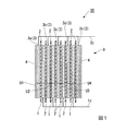
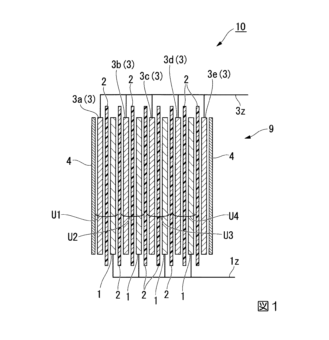
図1は本発明のリチウムイオン二次電池の一例を示す断面模式図である。平面視矩形状の負極3、セパレータ2、正極1が順に積層してなる電極ユニットが複数備えられた電極積層体9の断面を示している。電極積層体9は、負極3/セパレータ2/正極1が順に積層されてなる電極ユニットを4つ、即ち第一電極ユニットU1〜第四電極ユニットU4、を有する。電極積層体9において積層された各電極ユニットの間にはセパレータ2が配置されている。また、第四電極ユニットU4の外部側にはセパレータ2を介してさらに負極3e(3)が積層されている。リチウム金属箔4は、電極積層体9の最外層を構成する負極3a及び負極3eに対して接触するように設置されている。
FIG. 1 is a schematic sectional view showing an example of the lithium ion secondary battery of the present invention. The cross section of the electrode laminated body 9 with which the electrode unit formed by laminating | stacking the
<負極>
負極は、負極集電体として、貫通孔が多数形成された(パンチングされた)金属箔を有し、負極集電体の両面に、負極材から形成される負極活物質層が積層された構成を有することが好ましい。貫通孔を有する集電体を有することにより、負極活物質全体にわたってリチウムイオンが拡散し易くなる。
負極の形状は、平板状であることが好ましい。平板状としては、例えば平面視矩形状、平面視円板状等が挙げられる。
負極集電体の厚さは、例えば、1〜30μmが好ましい。
負極活物質層の厚さは、例えば、5μm〜50μmが好ましい。この範囲の厚さであると、負極活物質層の体積密度を後述の範囲に容易に調整することができる。
<Negative electrode>
The negative electrode has a metal foil having a large number of through holes (punched) as a negative electrode current collector, and a negative electrode active material layer formed of a negative electrode material is laminated on both surfaces of the negative electrode current collector It is preferable to have. By having a current collector having a through hole, lithium ions are easily diffused throughout the negative electrode active material.
The shape of the negative electrode is preferably a flat plate shape. Examples of the flat plate shape include a rectangular shape in plan view and a disk shape in plan view.
The thickness of the negative electrode current collector is preferably, for example, 1 to 30 μm.
The thickness of the negative electrode active material layer is preferably, for example, 5 μm to 50 μm. When the thickness is in this range, the volume density of the negative electrode active material layer can be easily adjusted to the range described later.
負極活物質層の体積密度は1.0g/cm3以下であり、0.7〜0.9g/cm3がより好ましい。負極活物質層の体積密度を上記数値範囲内とすることで、サイクル特性を高められやすくなる。上記下限値以上であると、放電容量を充分に確保することができる。上記下限値(1.0g/cm3)以下であると、リチウムイオンの吸収に伴う負極活物質層の膨張による、負極活物質層自体に対する応力(内部応力)を緩和し、負極の構造的な崩壊を防ぐことができる。
ここで負極活物質層の体積密度とは、リチウムプレドープ前の体積密度を意味する。
Volume density of the negative electrode active material layer has a 1.0 g / cm 3 or less, and more preferably 0.7~0.9g / cm 3. By setting the volume density of the negative electrode active material layer within the above numerical range, the cycle characteristics can be easily improved. When it is at least the above lower limit value, a sufficient discharge capacity can be secured. When the amount is not more than the lower limit (1.0 g / cm 3 ), stress (internal stress) on the negative electrode active material layer itself due to expansion of the negative electrode active material layer accompanying absorption of lithium ions is relieved, and the structure of the negative electrode Collapse can be prevented.
Here, the volume density of the negative electrode active material layer means the volume density before lithium pre-doping.
(体積密度の調整)
体積密度を調整する方法は特に限定されず、例えば、負極活物質の種類、配合量、平均粒子径等を調節することにより調整することができる。また、負極活物質層が形成された負極集電体を有する負極を2枚の平板状冶具の間に挟んで、負極活物質層の全面を厚み方向に均一に加圧する方法でも調整することができる。例えば、前記負極をロールプレス機などで加圧する方法によって負極の体積密度を調整することができる。
(Adjustment of volume density)
The method for adjusting the volume density is not particularly limited, and can be adjusted, for example, by adjusting the type, blending amount, average particle size, and the like of the negative electrode active material. Further, the negative electrode having the negative electrode current collector on which the negative electrode active material layer is formed is sandwiched between two flat jigs, and the entire surface of the negative electrode active material layer is uniformly pressed in the thickness direction. it can. For example, the volume density of the negative electrode can be adjusted by a method of pressurizing the negative electrode with a roll press or the like.
(体積密度の測定方法)
電極を所定の大きさ(例えば、φ16mm)で打ち抜いた測定試料を複数枚準備する。
各測定試料の質量を精密天秤にて秤量し、電極活物質層の質量を測定する。予め測定した負極集電体の質量を測定結果から差し引くことにより、測定試料中の電極活物質層の質量を算出することができる。また、断面出し加工した測定試料をSEMで観察する公知方法によって、電極活物質層の厚みを測定する。各測定値の平均値から下記式(1)に基づいて、電極活物質層の体積密度を算出することができる。
体積密度(g/cm3)=電極活物質層の質量(g)/[(電極活物質の厚み(cm)×打ち抜いた電極の面積(cm2)]・・・(1)
(Measurement method of volume density)
A plurality of measurement samples are prepared by punching electrodes with a predetermined size (for example, φ16 mm).
The mass of each measurement sample is weighed with a precision balance, and the mass of the electrode active material layer is measured. The mass of the electrode active material layer in the measurement sample can be calculated by subtracting the mass of the negative electrode current collector measured in advance from the measurement result. Further, the thickness of the electrode active material layer is measured by a publicly known method of observing a cross-section processed measurement sample with an SEM. Based on the following formula (1), the volume density of the electrode active material layer can be calculated from the average value of the measured values.
Volume density (g / cm 3 ) = Mass (g) of electrode active material layer / [(Thickness of electrode active material (cm) × Punched electrode area (cm 2 )] (1)
[負極材]
前記負極材としては、従来のリチウムイオン二次電池に使用される負極材が適用可能であり、例えば、前記負極活物質、粒子状導電助剤、繊維状導電助剤及びバインダーが配合されてなるものが挙げられる。
前記負極活物質としては、例えば酸化ケイ素、スズ等が挙げられ、酸化ケイ素が好ましい。
[Negative electrode material]
As the negative electrode material, a negative electrode material used in a conventional lithium ion secondary battery can be applied. For example, the negative electrode active material, a particulate conductive auxiliary, a fibrous conductive auxiliary and a binder are blended. Things.
Examples of the negative electrode active material include silicon oxide and tin, and silicon oxide is preferable.
(酸化ケイ素)
前記酸化ケイ素としては、一般式「SiOz(式中、zは0.5〜1.5のいずれかの数である。)」で表されるものが例示できる。ここで酸化ケイ素を「SiO」単位で見た場合、このSiOは、アモルファス状のSiOであるか、又はSi:SiO2のモル比が約1:1となるように、ナノクラスターのSiの周囲にSiO2が存在する、Si及びSiO2の複合物である。SiO2は、充放電時におけるSiの膨張及び収縮に対して緩衝作用を有すると推測される。
(Silicon oxide)
Examples of the silicon oxide include those represented by the general formula “SiO z (wherein z is any number from 0.5 to 1.5)”. Here, when the silicon oxide is viewed in “SiO” units, this SiO is amorphous SiO, or around the Si of the nanocluster so that the molar ratio of Si: SiO 2 is about 1: 1. This is a composite of Si and SiO 2 in which SiO 2 exists. SiO 2 is presumed to have a buffering action against the expansion and contraction of Si during charging and discharging.
前記酸化ケイ素の形状は特に制限されず、例えば、粉末状、粒子状等の酸化ケイ素を使用することができる。 The shape of the silicon oxide is not particularly limited, and for example, silicon oxide such as powder and particles can be used.
負極活物質が粒子状である場合、負極活物質の平均粒子径は、0.2〜20μmであることが好ましく、0.5〜10μmであることがより好ましく、1〜5μmであることがさらに好ましい。
負極活物質の平均粒子径を測定する方法としては、例えば、電子顕微鏡を用いて、負極材に使用する任意の負極活物質の粒子約100個の粒子径を計測し、その平均値を算出して求める方法が挙げられる。
負極活物質の平均粒子径を所望の値に調節する方法として、ボールミル等を用いる公知の手法で粉砕する方法が挙げられる。
When the negative electrode active material is particulate, the average particle diameter of the negative electrode active material is preferably 0.2 to 20 μm, more preferably 0.5 to 10 μm, and further preferably 1 to 5 μm. preferable.
As a method of measuring the average particle diameter of the negative electrode active material, for example, using an electron microscope, the particle diameter of about 100 particles of any negative electrode active material used for the negative electrode material is measured, and the average value is calculated. The method to ask for is mentioned.
Examples of a method for adjusting the average particle diameter of the negative electrode active material to a desired value include a method of pulverizing by a known method using a ball mill or the like.
前記負極材において、負極活物質、粒子状導電助剤、繊維状導電助剤及びバインダーの総配合量に対する、負極活物質の配合量の割合は、例えば、40〜85質量%とすることができる。負極活物質の前記配合量の割合が前記下限値以上であることで、リチウムイオン二次電池の放電容量がより向上し、負極活物質の前記配合量の割合が前記上限値以下であることで、負極構造の安定した維持が容易となる。 In the negative electrode material, the ratio of the amount of the negative electrode active material to the total amount of the negative electrode active material, the particulate conductive auxiliary, the fibrous conductive auxiliary and the binder can be, for example, 40 to 85% by mass. . When the proportion of the compounding amount of the negative electrode active material is not less than the lower limit value, the discharge capacity of the lithium ion secondary battery is further improved, and the proportion of the compounding amount of the negative electrode active material is not more than the upper limit value. Thus, stable maintenance of the negative electrode structure is facilitated.
(粒子状導電助剤)
前記粒子状導電助剤は、導電助剤として機能する粒子状のものであり、好ましいものとしては、アセチレンブラック、ケッチェンブラック等のカーボンブラック;黒鉛(グラファイト);フラーレン等が例示できる。
前記粒子状導電助剤は、一種を単独で用いてもよいし、二種以上を併用してもよい。
(Particulate conductive aid)
The particulate conductive aid is in the form of particles functioning as a conductive aid, and preferred examples include carbon black such as acetylene black and ketjen black; graphite (graphite); fullerene and the like.
The particulate conductive auxiliary may be used alone or in combination of two or more.
前記負極材において、負極活物質、粒子状導電助剤、繊維状導電助剤及びバインダーの総配合量に対する、粒子状導電助剤の配合量の割合は、例えば、3〜30質量%とすることができる。 In the negative electrode material, the ratio of the amount of the particulate conductive aid to the total amount of the negative electrode active material, the particulate conductive aid, the fibrous conductive aid and the binder is, for example, 3 to 30% by mass. Can do.
(繊維状導電助剤)
前記繊維状導電助剤は、導電助剤として機能する繊維状のものであり、好ましいものとしては、カーボンナノチューブ、カーボンナノホーンが例示できる。
(Fibrous conductive aid)
The fibrous conductive assistant is a fibrous substance that functions as a conductive assistant, and preferred examples include carbon nanotubes and carbon nanohorns.
繊維状導電助剤は、後述する負極活物質層中において、好ましくは負極活物質層全体に、網目構造を形成することで、負極活物質層の構造安定化に寄与すると共に、負極活物質層中に導電ネットワークを形成して、導電性の向上に寄与している推測される。
前記繊維状導電助剤は、一種を単独で用いてもよいし、二種以上を併用してもよい。
The fibrous conductive auxiliary agent contributes to the structural stabilization of the negative electrode active material layer by forming a network structure in the entire negative electrode active material layer, preferably in the negative electrode active material layer described later, and the negative electrode active material layer. It is presumed that a conductive network is formed therein and contributes to improvement of conductivity.
The said fibrous conductive support agent may be used individually by 1 type, and may use 2 or more types together.
繊維状導電助剤の平均繊維径は、2nm以上100nm未満であることが好ましく、5nm以上50nm以下であることがより好ましく、10nm以上30nm以下であることがさらに好ましい。
繊維状導電助剤の平均繊維径が2nm以上であると、負極材において繊維状炭素としての形態を維持可能な程度の剛性を有する。繊維状導電助剤の平均繊維径が100nm未満であると、添加量(重量)が少なくても、近傍にある負極活物質との接触確率をより高められる。
ここで、「平均繊維径」とは、導電助剤の長手方向に対して直交する断面における平均の外径を意味する。
The average fiber diameter of the fibrous conductive additive is preferably 2 nm or more and less than 100 nm, more preferably 5 nm or more and 50 nm or less, and further preferably 10 nm or more and 30 nm or less.
When the average fiber diameter of the fibrous conductive additive is 2 nm or more, the negative electrode material has rigidity sufficient to maintain the form of fibrous carbon. When the average fiber diameter of the fibrous conductive additive is less than 100 nm, even if the addition amount (weight) is small, the contact probability with the negative electrode active material in the vicinity can be further increased.
Here, the “average fiber diameter” means an average outer diameter in a cross section perpendicular to the longitudinal direction of the conductive additive.
繊維状導電助剤の平均繊維長は、0.1μm〜30μmであることが好ましく、0.5μm〜20μmであることがより好ましい。
繊維状導電助剤の長さが0.1μm以上であると、比較的長距離の導通に寄与する長さを維持するための剛性が得られ易い。繊維状導電助剤の長さが30μm以下であると、負極内における活物質や導電助剤等の分布の均一性を高められる。
ここで「平均繊維長」とは、長手方向における平均の長さを意味する。
The average fiber length of the fibrous conductive additive is preferably 0.1 μm to 30 μm, and more preferably 0.5 μm to 20 μm.
When the length of the fibrous conductive additive is 0.1 μm or more, it is easy to obtain rigidity for maintaining a length that contributes to relatively long-distance conduction. When the length of the fibrous conductive additive is 30 μm or less, the uniformity of the distribution of the active material, conductive additive and the like in the negative electrode can be improved.
Here, the “average fiber length” means an average length in the longitudinal direction.
繊維状導電助剤の平均繊維径を測定する方法としては、例えば、電子顕微鏡を用いて、負極材に使用する任意の導電助剤約100本について繊維径を計測し、その平均値を算出して求める方法が挙げられる。同様に、繊維状導電助剤の平均繊維長を測定する方法としては、例えば、電子顕微鏡を用いて、負極材に使用する任意の導電助剤約100本について繊維長を計測し、その平均値を算出する方法が挙げられる。 As a method of measuring the average fiber diameter of the fibrous conductive auxiliary, for example, using an electron microscope, the fiber diameter is measured for about 100 arbitrary conductive auxiliary agents used for the negative electrode material, and the average value is calculated. The method to ask for is mentioned. Similarly, as a method of measuring the average fiber length of the fibrous conductive additive, for example, using an electron microscope, the fiber length is measured for about 100 arbitrary conductive assistants used for the negative electrode material, and the average value is obtained. The method of calculating is mentioned.
繊維状導電助剤の長さ(平均繊維長)/直径(平均繊維径)で表されるアスペクト比(A)は、10〜10000が好ましく、100〜1000がさらに好ましい。
アスペクト比(A)が10以上であると、繊維状導電助剤と他の導電材や活物質との接触効率が高まり、負極材の導電性が向上する。アスペクト比(A)が10000以下であると、繊維状導電助剤の負極材における分散性が高まり、負極材の導電性がより向上する。
The aspect ratio (A) represented by the length (average fiber length) / diameter (average fiber diameter) of the fibrous conductive additive is preferably 10 to 10,000, and more preferably 100 to 1,000.
When the aspect ratio (A) is 10 or more, the contact efficiency between the fibrous conductive additive and the other conductive material or active material is increased, and the conductivity of the negative electrode material is improved. When the aspect ratio (A) is 10,000 or less, the dispersibility of the fibrous conductive additive in the negative electrode material is increased, and the conductivity of the negative electrode material is further improved.
前記負極材において、負極活物質、粒子状導電助剤、繊維状導電助剤及びバインダーの総配合量に対する、繊維状導電助剤の配合量の割合は、例えば、4〜25質量%とすることができる。繊維状導電助剤の前記配合量の割合が前記下限値以上であることで、繊維状導電助剤を用いたことによる効果がより顕著に得られ、繊維状導電助剤の前記配合量の割合が前記上限値以下であることで、粒子状導電助剤との併用による導電性向上の効果がより顕著に得られる。 In the negative electrode material, the ratio of the amount of the fibrous conductive additive to the total amount of the negative electrode active material, the particulate conductive additive, the fibrous conductive additive and the binder is, for example, 4 to 25% by mass. Can do. The ratio of the blending amount of the fibrous conductive additive is more prominently obtained by using the fibrous conductive additive because the ratio of the blending amount of the fibrous conductive assistant is not less than the lower limit. Is not more than the above upper limit value, the effect of improving the conductivity by the combined use with the particulate conductive additive can be obtained more remarkably.
前記負極材において、「粒子状導電助剤:繊維状導電助剤」の配合量の質量比率(配合質量比)は、例えば、90:10〜30:70とすることができる。粒子状導電助剤及び繊維状導電助剤の配合質量比がこのような範囲であることで、粒子状導電助剤及び繊維状導電助剤の併用により、導電性が向上する効果がより顕著に得られる。 In the negative electrode material, the mass ratio (blending mass ratio) of the blending amount of “particulate conduction aid: fibrous conduction aid” can be, for example, 90:10 to 30:70. When the blending mass ratio of the particulate conductive additive and the fibrous conductive additive is within such a range, the combined use of the particulate conductive additive and the fibrous conductive additive can more significantly improve the conductivity. can get.
負極活物質層において、繊維状導電助剤の含有量は、負極活物質層の総質量に対し、4質量%以上が好ましく、5〜8質量%がより好ましい。
負極活物質層における繊維状導電助剤の含有量が上記数値範囲内であることで、サイクル特性が高められやすくなる。
In the negative electrode active material layer, the content of the fibrous conductive additive is preferably 4% by mass or more, and more preferably 5 to 8% by mass with respect to the total mass of the negative electrode active material layer.
When the content of the fibrous conductive additive in the negative electrode active material layer is within the above numerical range, the cycle characteristics are easily improved.
(負極活物質の平均粒子径)/(繊維状導電助剤の平均繊維長)で表される比γは、0.2〜10が好ましく、0.5〜5がより好ましい。比γを上記数値範囲内とすることにより、負極活物質層内の導電経路(ネットワーク)が強靭となり、充放電に伴う膨張収縮による劣化が低減され、サイクル特性が向上しやすくなる。 The ratio γ expressed by (average particle diameter of the negative electrode active material) / (average fiber length of the fibrous conductive additive) is preferably 0.2 to 10, and more preferably 0.5 to 5. By setting the ratio γ within the above numerical range, the conductive path (network) in the negative electrode active material layer becomes tough, deterioration due to expansion / contraction due to charge / discharge is reduced, and the cycle characteristics are easily improved.
(バインダー)
前記バインダーは公知のものでよく、好ましいものとしては、ポリアクリル酸(PAA)、ポリアクリル酸リチウム(PAALi)、ポリフッ化ビニリデン(PVDF)、ポリフッ化ビニリデン−六フッ化プロピレン共重合体(PVDF−HFP)、スチレンブタジエンゴム(SBR)、ポリビニルアルコール(PVA)、ポリエチレンオキサイド(PEO)、ポリエチレングリコール(PEG)、カルボキシメチルセルロース(CMC)、ポリアクリルニトリル(PAN)、ポリイミド(PI)等が例示できる。
前記バインダーは、一種を単独で用いてもよいし、二種以上を併用してもよく、二種以上を併用する場合には、その組み合わせ及び比率は目的に応じて適宜選択すればよい。
(binder)
The binder may be a known one, and preferable examples thereof include polyacrylic acid (PAA), lithium polyacrylate (PAALi), polyvinylidene fluoride (PVDF), polyvinylidene fluoride-hexafluoropropylene copolymer (PVDF- Examples thereof include HFP), styrene butadiene rubber (SBR), polyvinyl alcohol (PVA), polyethylene oxide (PEO), polyethylene glycol (PEG), carboxymethyl cellulose (CMC), polyacrylonitrile (PAN), and polyimide (PI).
The binder may be used alone or in combination of two or more. When two or more are used in combination, the combination and ratio may be appropriately selected according to the purpose.
前記負極材において、負極活物質、粒子状導電助剤、繊維状導電助剤及びバインダーの総配合量に対する、バインダーの配合量の割合は、例えば、3〜30質量%とすることができる。バインダーの前記配合量の割合が前記下限値以上であることで、負極構造がより安定して維持され、バインダーの前記配合量の割合が前記上限値以下であることで、放電容量がより向上する。 In the negative electrode material, the ratio of the amount of the binder to the total amount of the negative electrode active material, the particulate conductive auxiliary, the fibrous conductive auxiliary and the binder can be, for example, 3 to 30% by mass. When the proportion of the blending amount of the binder is equal to or higher than the lower limit value, the negative electrode structure is more stably maintained, and when the proportion of the blending amount of the binder is equal to or lower than the upper limit value, the discharge capacity is further improved. .
(その他の成分)
前記負極材には、負極活物質、粒子状導電助剤、繊維状導電助剤及びバインダー以外に、これらに該当しないその他の成分がさらに配合されていてもよい。
前記その他の成分は、目的に応じて任意に選択でき、好ましいものとしては、前記配合成分(負極活物質、粒子状導電助剤、繊維状導電助剤、バインダー)を溶解又は分散させるための溶媒が例示できる。
このような、さらに溶媒が配合されてなる負極材は、使用時において流動性を有する液状組成物であることが好ましい。
(Other ingredients)
In addition to the negative electrode active material, the particulate conductive aid, the fibrous conductive aid and the binder, other components not corresponding to these may be further blended in the negative electrode material.
The other components can be arbitrarily selected according to the purpose, and as a preferable one, a solvent for dissolving or dispersing the compounding components (negative electrode active material, particulate conductive assistant, fibrous conductive assistant, binder). Can be illustrated.
Such a negative electrode material further mixed with a solvent is preferably a liquid composition having fluidity at the time of use.
前記溶媒は、前記配合成分の種類に応じて任意に選択でき、好ましいものとしては、水、有機溶媒が例示できる。
前記有機溶媒で好ましいものとしては、メタノール、エタノール、1−プロパノール、2−プロパノール等のアルコール;N−メチルピロリドン(NMP)、N,N−ジメチルホルムアミド(DMF)等の鎖状又は環状アミド;アセトン等のケトンが例示できる。
前記溶媒は、一種を単独で用いてもよいし、二種以上を併用してもよく、二種以上を併用する場合には、その組み合わせ及び比率は目的に応じて適宜選択すればよい。
The said solvent can be arbitrarily selected according to the kind of said mixing | blending component, As a preferable thing, water and an organic solvent can be illustrated.
Preferred examples of the organic solvent include alcohols such as methanol, ethanol, 1-propanol and 2-propanol; linear or cyclic amides such as N-methylpyrrolidone (NMP) and N, N-dimethylformamide (DMF); acetone And the like.
The solvents may be used alone or in combination of two or more, and when two or more are used in combination, the combination and ratio may be appropriately selected according to the purpose.
負極材における前記溶媒の配合量は、特に限定されず、目的に応じて適宜調節すればよい。例えば、溶媒が配合された液状組成物である負極材を塗工及び乾燥させて負極活物質層を形成する場合には、この液状組成物が塗工に適した粘度となるように、溶媒の配合量を調節すればよい。具体的には、負極材において、配合成分の総量に対する、溶媒以外の配合成分の総量の割合が、好ましくは5〜60質量%、より好ましくは10〜35質量%となるように、溶媒の配合量を調節するとよい。 The amount of the solvent in the negative electrode material is not particularly limited, and may be adjusted as appropriate according to the purpose. For example, when a negative electrode material that is a liquid composition containing a solvent is applied and dried to form a negative electrode active material layer, the solvent composition is adjusted so that the liquid composition has a viscosity suitable for coating. What is necessary is just to adjust a compounding quantity. Specifically, in the negative electrode material, the blending of the solvent so that the ratio of the total amount of the blending components other than the solvent to the total amount of the blending components is preferably 5 to 60% by mass, more preferably 10 to 35% by mass. Adjust the amount.
前記その他の成分として、前記溶媒以外の成分(その他の固体成分)を配合する場合、前記負極材において、溶媒以外の配合成分の総量に対する、その他の固体成分の配合量の割合は、10質量%以下であることが好ましく、5質量%以下であることがより好ましい。 When a component other than the solvent (other solid component) is blended as the other component, the proportion of the blended amount of the other solid component with respect to the total amount of the blended component other than the solvent in the negative electrode material is 10% by mass. Or less, more preferably 5% by mass or less.
前記負極材は、前記負極活物質、粒子状導電助剤、繊維状導電助剤、バインダー、及び必要に応じてその他の成分を配合することで製造できる。 The said negative electrode material can be manufactured by mix | blending the said negative electrode active material, a particulate-form conductive support agent, a fibrous conductive support agent, a binder, and another component as needed.
負極活物質層が形成される負極集電体の材料として、例えば、銅(Cu)、チタン(Ti)、ニッケル(Ni)、ステンレス鋼等が挙げられる。
<正極>
正極は、正極集電体として、貫通孔が多数形成された(パンチングされた)アルミ箔を有し、正極集電体の両面に、正極材から形成される正極活物質層が積層された構成を有することが好ましい。正極活物質全体にわたってリチウムイオンが拡散し易くなるからである。
正極の形状は、平板状であることが好ましい。平板状としては、例えば平面視矩形状、平面視円板状等が挙げられる。
正極集電体の厚さは、例えば、1〜30μmが好ましい。
正極活物質層の厚さは、例えば、5μm〜80μmが好ましい。
Examples of the material of the negative electrode current collector on which the negative electrode active material layer is formed include copper (Cu), titanium (Ti), nickel (Ni), and stainless steel.
<Positive electrode>
The positive electrode has, as a positive electrode current collector, an aluminum foil having a number of through holes (punched), and a positive electrode active material layer formed from a positive electrode material is laminated on both surfaces of the positive electrode current collector It is preferable to have. This is because lithium ions easily diffuse throughout the positive electrode active material.
The shape of the positive electrode is preferably a flat plate shape. Examples of the flat plate shape include a rectangular shape in plan view and a disk shape in plan view.
The thickness of the positive electrode current collector is preferably, for example, 1 to 30 μm.
The thickness of the positive electrode active material layer is preferably 5 μm to 80 μm, for example.
[正極材]
前記正極材としては、従来のリチウムイオン二次電池に使用される正極材が適用可能であり、例えば、正極活物質、バインダー及び溶媒、並びに必要に応じて導電助剤等が配合されてなる正極材が挙げられる。
[Positive electrode material]
As the positive electrode material, a positive electrode material used in a conventional lithium ion secondary battery can be applied. For example, a positive electrode in which a positive electrode active material, a binder and a solvent, and a conductive additive or the like are blended as necessary. Materials.
正極活物質としては、一般式「LiMxOy(式中、Mは金属であり;x及びyは、金属Mと酸素Oとの組成比である。)」で表される金属酸リチウム化合物が例示できる。
このような金属酸リチウム化合物としては、コバルト酸リチウム(LiCoO2)、ニッケル酸リチウム(LiNiO2)、マンガン酸リチウム(LiMn2O4)等が例示でき、類似の組成であるオリビン型リン酸鉄リチウム(LiFePO4)を用いることもできる。
前記金属酸リチウム化合物は、前記一般式において、Mが複数種のものであってもよく、このような金属酸リチウム化合物としては、一般式「LiM1 pM2 qM3 rOy(式中、M1、M2及びM3は互いに異なる種類の金属であり;p、q、r及びyは、金属M1、M2及びM3と酸素Oとの組成比である。)」で表されるものが例示できる。ここで、p+q+r=xである。このような金属酸リチウム化合物としては、LiNi0.33Mn0.33Co0.33O2等が例示できる。
正極活物質は、一種を単独で用いてもよいし、二種以上を併用してもよい。
As the positive electrode active material, a lithium metal acid compound represented by the general formula “LiM x O y (wherein M is a metal; x and y are composition ratios of metal M and oxygen O)” Can be illustrated.
Examples of such a metal acid lithium compound include lithium cobaltate (LiCoO 2 ), lithium nickelate (LiNiO 2 ), lithium manganate (LiMn 2 O 4 ), and the like, and olivine iron phosphate having a similar composition. Lithium (LiFePO 4 ) can also be used.
In the above general formula, M may be a plurality of types of the lithium metal acid compound. As such a metal acid lithium compound, the general formula “LiM 1 p M 2 q M 3 r O y (formula Where M 1 , M 2 and M 3 are different types of metals; p, q, r and y are the composition ratios of the metals M 1 , M 2 and M 3 and oxygen O). What is represented can be exemplified. Here, p + q + r = x. Examples of such a metal acid lithium compound include LiNi 0.33 Mn 0.33 Co 0.33 O 2 .
A positive electrode active material may be used individually by 1 type, and may use 2 or more types together.
正極における導電助剤としては、例えば、黒鉛(グラファイト);ケッチェンブラック、アセチレンブラック等のカーボンブラック;カーボンナノチューブ;カーボンナノホーン;グラフェン;フラーレン等が挙げられる。
正極における前記導電助剤は、一種を単独で用いてもよいし、二種以上を併用してもよい。
Examples of the conductive additive in the positive electrode include graphite (graphite); carbon black such as ketjen black and acetylene black; carbon nanotube; carbon nanohorn; graphene; fullerene.
The said conductive support agent in a positive electrode may be used individually by 1 type, and may use 2 or more types together.
正極におけるバインダー、溶媒及び集電体は、いずれも負極におけるバインダー、溶媒及び集電体と同様のものでよい。 The binder, solvent and current collector in the positive electrode may all be the same as the binder, solvent and current collector in the negative electrode.
前記正極材における、配合成分の総量に対する、前記正極活物質、バインダー、溶媒、及び導電助剤のそれぞれの配合量の割合は、前記負極材における、配合成分の総量に対する、前記負極活物質、バインダー、溶媒、及び導電助剤のそれぞれの配合量の割合と同様とすることができる。 The ratio of the amount of each of the positive electrode active material, the binder, the solvent, and the conductive additive to the total amount of the compounding components in the positive electrode material is the ratio of the negative electrode active material and the binder to the total amount of the compounding components in the negative electrode material. , The solvent, and the proportion of each of the conductive additives can be the same.
<電解質>
本発明に備えられる前記電解質は特に限定されず、例えば、公知のリチウムイオン二次電池で使用されるリチウム塩が挙げられる。前記電解質は、有機溶媒中に溶解された電解液の状態で備えられてもよいし、さらに前記電解液がゲルポリマー中に保持されたゲル電解質の状態で備えられていてもよい。
前記電解液は特に限定されず、例えば、公知のリチウムイオン二次電池で使用される公知の電解液等が適用可能である。電解液としては、有機溶媒に電解質塩を溶解した混合溶液が例示できる。有機溶媒としては、高電圧に対する耐性を有するものが好ましく、例えば、エチレンカーボネート、プロピレンカーボネート、ジメチルカーボネート、γ−ブチロラクトン、スルホラン、ジメチルスルホキシド、アセトニトリル、ジメチルホルムアミド、ジメチルアセトアミド、1,2−ジメトキシエタン、1,2−ジエトキシエタン、テトロヒドラフラン、2−メチルテトラヒドロフラン、ジオキソラン、メチルアセテートなどの極性溶媒、又はこれら溶媒の2種類以上の混合物が挙げられる。電解質塩としては、LiClO4、LiPF6、LiBF4、LiAsF6、LiCF6、LiCF3CO2、LiPF6SO3、LiN(SO3CF3)2、Li(SO2CF2CF3)2、LiN(COCF3)2及びLiN(COCF2CF3)2等のリチウムを含む塩、又はこれら塩の2種以上の混合物が挙げられる。
<Electrolyte>
The said electrolyte with which this invention is equipped is not specifically limited, For example, the lithium salt used with a well-known lithium ion secondary battery is mentioned. The electrolyte may be provided in a state of an electrolytic solution dissolved in an organic solvent, or may be provided in a state of a gel electrolyte in which the electrolytic solution is held in a gel polymer.
The said electrolyte solution is not specifically limited, For example, the well-known electrolyte solution etc. which are used with a well-known lithium ion secondary battery are applicable. Examples of the electrolytic solution include a mixed solution in which an electrolyte salt is dissolved in an organic solvent. As the organic solvent, those having resistance against high voltage are preferable, for example, ethylene carbonate, propylene carbonate, dimethyl carbonate, γ-butyrolactone, sulfolane, dimethyl sulfoxide, acetonitrile, dimethylformamide, dimethylacetamide, 1,2-dimethoxyethane, Examples include polar solvents such as 1,2-diethoxyethane, tetrohydrafuran, 2-methyltetrahydrofuran, dioxolane, and methyl acetate, or a mixture of two or more of these solvents. Examples of the electrolyte salt include LiClO 4 , LiPF 6 , LiBF 4 , LiAsF 6 , LiCF 6 , LiCF 3 CO 2 , LiPF 6 SO 3 , LiN (SO 3 CF 3 ) 2 , Li (SO 2 CF 2 CF 3 ) 2 , Examples thereof include salts containing lithium such as LiN (COCF 3 ) 2 and LiN (COCF 2 CF 3 ) 2 , or a mixture of two or more of these salts.
<セパレータ>
正極と負極の間には、これらの短絡を防止するセパレータが配置されていることが好ましい。
セパレータの材料としては、例えば、多孔性樹脂膜、不織布、ガラスファイバー等が挙げられる。
また、前記セパレータとして、正極活物質層の表面又は負極活物質層の表面に形成され、正極と負極を絶縁し、電解液を保持及び透過させることが可能な多孔性絶縁層も適用可能である。多孔性絶縁層は、例えば、絶縁性無機粒子及びバインダー樹脂を含む組成物を負極又は正極の表面に塗工して乾燥させる公知方法によって形成される。
セパレータの形状は、平板状であることが好ましい。平板状としては、例えば平面視矩形状、平面視円板状等が挙げられる。
セパレータの厚みは、0.5μm〜50μmが好ましい。
<Separator>
It is preferable that the separator which prevents these short circuits is arrange | positioned between the positive electrode and the negative electrode.
Examples of the material for the separator include a porous resin film, a nonwoven fabric, and glass fiber.
Further, as the separator, a porous insulating layer that is formed on the surface of the positive electrode active material layer or the surface of the negative electrode active material layer and that can insulate the positive electrode and the negative electrode and hold and transmit the electrolytic solution is also applicable. . The porous insulating layer is formed, for example, by a known method in which a composition containing insulating inorganic particles and a binder resin is applied to the surface of the negative electrode or the positive electrode and dried.
The shape of the separator is preferably a flat plate shape. Examples of the flat plate shape include a rectangular shape in plan view and a disk shape in plan view.
The thickness of the separator is preferably 0.5 μm to 50 μm.
<リチウム金属箔>
リチウム金属箔は、リチウムプレドープ処理におけるリチウムの供給源となる。
リチウム金属箔の厚さは、例えば、10μm〜500μmが好ましい。
例えば、電極積層体及び電解液を外装体に封入したセルを得て、所定温度において放置することによってリチウムプレドープを自然に進行させてもよいし、セルを加圧しながらリチウムプレドープを行ってもよい。セルを加圧する方法は特に限定されず、例えば、セルを2枚の平板状冶具の間に挟んで、セルの全面を厚み方向に均一に加圧する方法が挙げられる。リチウムプレドープ中のセルの加圧は必須ではないが、プレドープの進行に伴って負極活物質層が膨れる傾向があるため、加圧によってこの膨れを抑制することが好ましい。また、リチウムプレドープ時にセルを冶具に挟んで体積一定を保持することは、その保持と、負極活物質層及びセルの内圧の上昇との拮抗によって、セルを加圧することになる。したがって、リチウムプレドープ時の加圧の方法として、積極的に外部から圧力を加える方法、及びセルの体積を一定に保ってセルの内圧の上昇をセルの加圧に転換する方法、の少なくとも一方を採用することができる。
<Lithium metal foil>
The lithium metal foil serves as a lithium supply source in the lithium pre-doping process.
As for the thickness of lithium metal foil, 10 micrometers-500 micrometers are preferable, for example.
For example, a cell in which an electrode laminate and an electrolyte solution are enclosed in an outer package is obtained, and the lithium pre-doping may be allowed to proceed naturally by leaving it at a predetermined temperature, or by performing lithium pre-doping while pressurizing the cell. Also good. The method for pressurizing the cell is not particularly limited, and examples thereof include a method in which the cell is sandwiched between two flat jigs and the entire surface of the cell is uniformly pressed in the thickness direction. Although pressurization of the cell during lithium pre-doping is not essential, since the negative electrode active material layer tends to swell as the pre-doping progresses, it is preferable to suppress this swell by pressurization. Also, holding the cell constant by holding the cell between the jigs during lithium pre-doping pressurizes the cell by antagonizing the holding and the increase in the internal pressure of the negative electrode active material layer and the cell. Therefore, at least one of a method of positively applying pressure from the outside and a method of converting the increase in the internal pressure of the cell to the pressurization of the cell while keeping the volume of the cell constant as a method of pressurization during lithium pre-doping Can be adopted.
リチウムプレドープ工程においてセルを加圧する程度としては、負極を構成する負極材の種類にもよるが、負極の厚み方向に対して、5kgf/cm2以上12kgf/cm2の圧力にて加圧することが好ましい。ここで、1kgf=9.8Nである。
5kgf/cm2未満であると、セルの膨れを防止する効果が得られない場合がある。12kgf/cm2超であると、セルの膨れを防止できるが、負極活物質層及び正極活物質層を物理的に押しつぶす恐れがある。
The extent of pressurizing the cell in a lithium pre-doping process, depending on the kind of the negative electrode material constituting the negative electrode, the thickness direction of the negative electrode, be pressurized at a pressure of 5 kgf / cm 2 or more 12 kgf / cm 2 Is preferred. Here, 1 kgf = 9.8 N.
If it is less than 5 kgf / cm 2 , the effect of preventing cell swelling may not be obtained. If it exceeds 12 kgf / cm 2 , cell swelling can be prevented, but the negative electrode active material layer and the positive electrode active material layer may be physically crushed.
≪リチウムイオン二次電池の製造方法≫
本発明のリチウムイオン二次電池の製造方法としては、以下の3つの工程を含むことが好ましい。
工程(1)負極、正極が離間した状態(即ち、短絡しないように絶縁された状態)で配置された電極ユニットを形成する。
工程(2)電極ユニットを外装体の内側に配置する。
工程(3)電解質を外装体の内側に封入する。
工程(1)においては、負極と正極の間にセパレータを設けた電極ユニットとしてもよい。
工程(1)においては電極ユニットを複数設置して電極積層体としてもよい。
工程(1)の後に、電極ユニット(又は電極積層体)の最外層に、リチウム金属箔を載置してもよい。
≪Method for manufacturing lithium ion secondary battery≫
The method for producing a lithium ion secondary battery of the present invention preferably includes the following three steps.
Step (1) An electrode unit arranged in a state where the negative electrode and the positive electrode are separated (ie, insulated so as not to be short-circuited) is formed.
Process (2) An electrode unit is arrange | positioned inside an exterior body.
Step (3) The electrolyte is sealed inside the outer package.
In the step (1), an electrode unit in which a separator is provided between the negative electrode and the positive electrode may be used.
In the step (1), a plurality of electrode units may be installed to form an electrode laminate.
After the step (1), a lithium metal foil may be placed on the outermost layer of the electrode unit (or electrode laminate).
負極の作製方法としては、例えば、パンチングされた板状負極集電体の第一面に負極材を塗工して負極活物質層を設け、第二面にも必要に応じて負極活物質層を設ける方法が挙げられる。その後、負極活物質層の体積密度を調整するために前記プレス処理を行うことが好ましい。
同様に、正極の作製方法としては、例えば、パンチングされた板状正極集電体の第一面に正極材を塗工して正極活物質層を設け、第二面にも必要に応じて正極活物質層を設ける方法が挙げられる。
As a method for producing the negative electrode, for example, a negative electrode material is applied to the first surface of the punched plate-shaped negative electrode current collector to provide a negative electrode active material layer, and the negative electrode active material layer is also provided on the second surface as necessary. The method of providing is mentioned. Then, it is preferable to perform the said press process in order to adjust the volume density of a negative electrode active material layer.
Similarly, as a method for producing the positive electrode, for example, a positive electrode material is applied to the first surface of the punched plate-shaped positive electrode current collector to provide a positive electrode active material layer, and the positive electrode is formed on the second surface as necessary. The method of providing an active material layer is mentioned.
以下、実施例を示して本発明についてさらに詳しく説明する。ただし、本発明は以下に示す実施例に何ら限定されない。 Hereinafter, the present invention will be described in more detail with reference to examples. However, the present invention is not limited to the following examples.
本実施例で使用した原料を以下に示す。
(負極活物質)
・一酸化ケイ素粒子(平均粒子径1μm)
(導電助剤)
・アセチレンブラック(電気化学工業社製、商品名HS−100、平均粒子径48nm)
・カーボンナノチューブA(Swent社製、商品名SMW、平均繊維径10nm、平均繊維長4.5μm)
・カーボンナノチューブB(丸紅情報システムズ株式会社製、商品名Flotube、平均繊維径10〜15nm、平均繊維長10μm)
(バインダー)
・スチレン−ブタジエン樹脂(以下、「SBR」と略記する)(JSR社製)
(有機溶媒)
・エチレンカーボネート(以下、「EC」と略記する)(キシダ化学社製)
・プロピレンカーボネート(以下、「PC」と略記する)(キシダ化学社製)
The raw materials used in this example are shown below.
(Negative electrode active material)
・ Silicon monoxide particles (average particle size 1μm)
(Conductive aid)
Acetylene black (manufactured by Denki Kagaku Kogyo Co., Ltd., trade name HS-100, average particle size 48 nm)
Carbon nanotube A (manufactured by Swen, trade name SMW,
Carbon nanotube B (manufactured by Marubeni Information Systems Co., Ltd., trade name: Flotube, average fiber diameter: 10-15 nm, average fiber length: 10 μm)
(binder)
Styrene-butadiene resin (hereinafter abbreviated as “SBR”) (manufactured by JSR)
(Organic solvent)
・ Ethylene carbonate (hereinafter abbreviated as “EC”) (manufactured by Kishida Chemical Co., Ltd.)
Propylene carbonate (hereinafter abbreviated as “PC”) (Kishida Chemical Co., Ltd.)
[実施例1]
(負極材の製造)
一酸化ケイ素(SiO、平均粒子径1μm、69質量部)、アセチレンブラック(10質量部)、カーボンナノチューブA(4質量部)、ポリアクリル酸リチウム(全酸基の30モル%がリチウム塩とされたもの、以下、「PAALi」と略記することがある、13質量部)、及びSBR(4質量部)を試薬瓶に入れ、さらにここに蒸留水を添加して濃度調整した後、ディスパーを用いて、この濃度調整したものを3000rpmで90分間混合した。次いで、超音波ホモジナイザーを用いてこの混合物を10分間分散処理した後、再度、自公転ミキサーを用いてこの分散物を2000rpmで3分間混合することにより、負極材を得た。ここまでの操作は、すべて25℃で行った。
[Example 1]
(Manufacture of negative electrode materials)
Silicon monoxide (SiO, average particle diameter of 1 μm, 69 parts by mass), acetylene black (10 parts by mass), carbon nanotube A (4 parts by mass), lithium polyacrylate (30 mol% of all acid groups are lithium salts) In the following, 13 parts by mass), which may be abbreviated as “PAALi”, and SBR (4 parts by mass) are placed in a reagent bottle, and distilled water is added thereto to adjust the concentration. Then, this adjusted concentration was mixed for 90 minutes at 3000 rpm. Next, this mixture was subjected to a dispersion treatment for 10 minutes using an ultrasonic homogenizer, and then this dispersion was again mixed for 3 minutes at 2000 rpm using a self-revolving mixer to obtain a negative electrode material. All the operations so far were performed at 25 ° C.
(負極の製造)
ダイヘッドが装着された塗工機を用いて、厚さ10μmのパンチング銅箔(穴径0.3mm、空孔率16.7%、福田金属箔粉工業社製)の両面に、上記で得られた負極材を塗布した。この際の条件は、塗工速度2m/min、乾燥温度100℃であった。その後、ロールプレス機を用いて、表1の体積密度となるような加圧条件でプレスすることによって、集電体である銅箔上の両面に厚さ、それぞれ25μmの負極活物質層を形成して、負極を得た。得られた負極は、負極活物質層部分(104×62mm)と、未塗工部分(タブ部分、2×2cm)の寸法であった。
前述した方法によって求めた負極活物質層の体積密度は0.8g/cm3であった。
また、負極活物質層の総質量に対する繊維状導電助剤の含有量は4質量%、前記アスペクト比=450(=4.5μm/0.01μm)、前記γ比=0.22(=1μm/4.5μm)であった。
(Manufacture of negative electrode)
Using a coating machine equipped with a die head, the above is obtained on both sides of a 10 μm-thick punched copper foil (hole diameter: 0.3 mm, porosity: 16.7%, manufactured by Fukuda Metal Foil Powder Co., Ltd.) A negative electrode material was applied. The conditions at this time were a coating speed of 2 m / min and a drying temperature of 100 ° C. Thereafter, using a roll press machine, the negative electrode active material layer having a thickness of 25 μm is formed on both sides of the copper foil as the current collector by pressing under pressure conditions such that the volume density shown in Table 1 is achieved. Thus, a negative electrode was obtained. The obtained negative electrode had dimensions of a negative electrode active material layer portion (104 × 62 mm) and an uncoated portion (tab portion, 2 × 2 cm).
The volume density of the negative electrode active material layer determined by the method described above was 0.8 g / cm 3 .
Further, the content of the fibrous conductive additive relative to the total mass of the negative electrode active material layer is 4% by mass, the aspect ratio = 450 (= 4.5 μm / 0.01 μm), and the γ ratio = 0.22 (= 1 μm / 4.5 μm).
(正極材の製造)
ニッケル・コバルト・マンガン酸リチウム(Ni:Co:Mn=1:1:1、LiNMC)(93質量部)と、ポリフッ化ビニリデン(PVDF)(4質量部)と、導電助剤であるカーボンブラック(3質量部)とを混合して正極混合材を調製し、これをN−メチルピロリドン(NMP)中に分散させて、正極材(スラリー)を得た。
(Manufacture of positive electrode material)
Nickel, cobalt, lithium manganate (Ni: Co: Mn = 1: 1: 1, LiNMC) (93 parts by mass), polyvinylidene fluoride (PVDF) (4 parts by mass), and carbon black ( 3 parts by mass) was mixed to prepare a positive electrode mixed material, which was dispersed in N-methylpyrrolidone (NMP) to obtain a positive electrode material (slurry).
(正極の製造)
負極の製造工程と同様に、ダイヘッドが装着された塗工機を用いて、厚さ15μmのパンチングAl箔(穴径0.3mm、空孔率16.7%、福田金属箔粉工業社製)の両面に、上記で得られた正極材を塗布した。この際の条件は、塗工速度2m/min、乾燥温度140℃であった。その後、ロールプレス機を用いてプレスすることによって、集電体である銅箔上の両面に厚さ、それぞれ60μmの正極活物質層を形成して、正極を得た。得られた正極は、正極活物質層部分(102×60mm)と、未塗工部分(タブ部分、2×2cm)の寸法であった。
(Manufacture of positive electrode)
Similar to the negative electrode manufacturing process, using a coating machine equipped with a die head, a 15 μm-thick punched Al foil (hole diameter 0.3 mm, porosity 16.7%, manufactured by Fukuda Metal Foil Powder Industry Co., Ltd.) The positive electrode material obtained above was applied to both sides of the above. The conditions at this time were a coating speed of 2 m / min and a drying temperature of 140 ° C. Then, by pressing using a roll press machine, a positive electrode active material layer having a thickness of 60 μm was formed on both surfaces of a copper foil as a current collector to obtain a positive electrode. The obtained positive electrode had dimensions of a positive electrode active material layer portion (102 × 60 mm) and an uncoated portion (tab portion, 2 × 2 cm).
(電解液の製造)
有機溶媒として、EC及びPCの混合溶媒(EC:PC=30:70(体積比))をポリ容器に量り取り、ここにシュウ酸リチウム−三フッ化ホウ素錯体を加えて、シュウ酸リチウム−三フッ化ホウ素錯体中のリチウム原子の濃度が1.0モル/kgとなるようにし、23℃で混合することにより、電解液を得た。
(Manufacture of electrolyte)
As an organic solvent, a mixed solvent of EC and PC (EC: PC = 30: 70 (volume ratio)) is weighed into a plastic container, to which a lithium oxalate-boron trifluoride complex is added, and lithium oxalate-3 The concentration of lithium atoms in the boron fluoride complex was adjusted to 1.0 mol / kg and mixed at 23 ° C. to obtain an electrolytic solution.
(リチウムイオン二次電池の製造)
図1に示す電極積層体9を備えたリチウムイオン二次電池10を以下の方法で製造した。上記で作製した負極3及び正極1の間に厚さ25μm、表面積42cm×57cmのセパレータ2(積水化学工業(株)社製)を配置して積層した電極ユニット(負極/セパレータ/正極)を得た。この電極ユニットを4つ準備し、隣接するユニット同士の正極1と負極3とを向い合せて、その間にセパレータ2を配置して第一から第四電極ユニットU1〜U4を積層した。この積層体の最外層は、第一ユニットU1の負極3aと第四ユニットU4の正極1である。最外層の第四ユニットU4の正極1の外部側の表面にセパレータ2を介して別の負極3eを設置し、電極積層体9を得た。
電極積層体9の最外層の両面に、パンチング銅箔とほぼ同面積の厚み100μmのリチウム金属箔4をそれぞれ載置して、リチウム金属箔4が最外層に設置された電極積層体9を得た(図1参照)。
(Manufacture of lithium ion secondary batteries)
A lithium ion
On both surfaces of the outermost layer of the electrode laminate 9, a
(リチウムプレドープ工程)
上記で得られた電極積層体の負極及び正極から突出させた前記端子用タブが外部へ突出するように、アルミニウムラミネートフィルムを配置し、電極積層体に電解液を注液後、このフィルムの外周をラミネート加工して電極積層体を真空封止した。その後、得られたセルを加圧治具にセットし、セルを3.3kg/cm2の力で加圧状態とし、25℃の恒温槽中にて、48h静置することによりリチウムプレドープ処理を行い、ラミネートセルを製造した。作製した電池の定格容量は1000mAhである。
この後、製造したラミネートセルの初回充電を行う際にも、セルを3.3kg/cm2の力で加圧状態とした。
(Lithium pre-doping process)
An aluminum laminate film is arranged so that the terminal tabs projected from the negative electrode and the positive electrode of the electrode laminate obtained above are projected to the outside, and an electrolyte is poured into the electrode laminate, and then the outer periphery of this film Was laminated to vacuum seal the electrode laminate. Thereafter, the obtained cell was set in a pressure jig, the cell was brought into a pressurized state with a force of 3.3 kg / cm 2 , and left in a constant temperature bath at 25 ° C. for 48 hours to perform lithium pre-doping treatment. The laminate cell was manufactured. The rated capacity of the manufactured battery is 1000 mAh.
Thereafter, when the manufactured laminate cell was charged for the first time, the cell was put into a pressurized state with a force of 3.3 kg / cm 2 .
[実施例2]
負極材の製造において、カーボンナノチューブAの量を3質量部に変更した以外は、実施例1と同様にラミネートセルを製造した。
前述した方法によって求めた負極活物質層の体積密度は0.8g/cm3であった。
また、負極活物質層の総質量に対する繊維状導電助剤の含有量は3質量%、前記アスペクト比=450(=4.5μm/0.01μm)、前記γ比=0.22(=1μm/4.5μm)であった。
[Example 2]
In the production of the negative electrode material, a laminate cell was produced in the same manner as in Example 1 except that the amount of the carbon nanotube A was changed to 3 parts by mass.
The volume density of the negative electrode active material layer determined by the method described above was 0.8 g / cm 3 .
Further, the content of the fibrous conductive additive relative to the total mass of the negative electrode active material layer is 3% by mass, the aspect ratio = 450 (= 4.5 μm / 0.01 μm), and the γ ratio = 0.22 (= 1 μm / 4.5 μm).
[実施例3]
負極材の製造において、カーボンナノチューブAをカーボンナノチューブBに変更した以外は、実施例2と同様にラミネートセルを製造した。
前述した方法によって求めた負極活物質層の体積密度は0.8g/cm3であった。
また、負極活物質層の総質量に対する繊維状導電助剤の含有量は3質量%、前記アスペクト比=667〜1000{=(10μm/0.015μm)〜(10μm/0.01μm)}、前記γ比=0.10(=1μm/10μm)であった。
[Example 3]
A laminate cell was produced in the same manner as in Example 2 except that the carbon nanotube A was changed to the carbon nanotube B in the production of the negative electrode material.
The volume density of the negative electrode active material layer determined by the method described above was 0.8 g / cm 3 .
In addition, the content of the fibrous conductive additive relative to the total mass of the negative electrode active material layer is 3% by mass, the aspect ratio = 667 to 1000 {= (10 μm / 0.015 μm) to (10 μm / 0.01 μm)}, The γ ratio was 0.10 (= 1 μm / 10 μm).
[比較例1]
負極の製造において、負極作製時のプレスによる加圧条件を適宜変更した以外は、実施例1と同様にラミネートセルを製造した。
前述した方法によって求めた負極活物質層の体積密度は1.1g/cm3であった。
また、負極活物質層の総質量に対する繊維状導電助剤の含有量は4質量%、前記アスペクト比=450(=4.5μm/0.01μm)、前記γ比=0.22(=1μm/4.5μm)であった。
[Comparative Example 1]
In the production of the negative electrode, a laminate cell was produced in the same manner as in Example 1 except that the pressurizing conditions by pressing during the production of the negative electrode were appropriately changed.
The volume density of the negative electrode active material layer determined by the method described above was 1.1 g / cm 3 .
Further, the content of the fibrous conductive additive relative to the total mass of the negative electrode active material layer is 4% by mass, the aspect ratio = 450 (= 4.5 μm / 0.01 μm), and the γ ratio = 0.22 (= 1 μm / 4.5 μm).
[比較例2]
負極の製造において、カーボンナノチューブAをカーボンナノチューブBに変更し、且つ、負極作製時のプレスによる加圧条件を適宜変更した以外は、実施例1と同様にラミネートセルを製造した。
前述した方法によって求めた負極活物質層の体積密度は1.1g/cm3であった。
また、負極活物質層の総質量に対する繊維状導電助剤の含有量は4質量%、前記アスペクト比=667〜1000{=(10μm/0.015μm)〜(10μm/0.01μm)}、前記γ比=0.10(=1μm/10μm)であった。
[Comparative Example 2]
In the production of the negative electrode, a laminate cell was produced in the same manner as in Example 1 except that the carbon nanotube A was changed to the carbon nanotube B, and the pressurizing condition by pressing during the production of the negative electrode was appropriately changed.
The volume density of the negative electrode active material layer determined by the method described above was 1.1 g / cm 3 .
In addition, the content of the fibrous conductive additive relative to the total mass of the negative electrode active material layer is 4% by mass, the aspect ratio = 667 to 1000 {= (10 μm / 0.015 μm) to (10 μm / 0.01 μm)}, The γ ratio was 0.10 (= 1 μm / 10 μm).
(リチウムイオン二次電池のサイクル特性の評価)
作製した各リチウムイオン二次電池について、25℃において0.1Cの定電流定電圧充電を、上限電圧4.2Vとして電流値が0.05Cに収束するまで行った後、0.1Cの定電流放電を2.5Vまで行った。次いで、充放電電流を0.5Cとして同様の方法で、充放電サイクルを3回繰り返し行い、リチウムイオン二次電池の状態を安定させた。次いで、充放電電流を0.2Cとして同様の方法で、充放電を行い、容量発現率({[1サイクル目の放電容量(mAh)]/[定格容量(mAh)]}×100)(%)、充放電電流を1Cとして同様の方法で、充放電サイクルを繰り返し行い200サイクルでの容量維持率({[200サイクル目の放電容量(mAh)]/[1サイクル目の放電容量(mAh)]}×100)(%)を算出した。この結果を表1に示す。
(Evaluation of cycle characteristics of lithium ion secondary batteries)
About each produced lithium ion secondary battery, after performing constant-current constant-voltage charge of 0.1C at 25 degreeC until the electric current value converges to 0.05C as upper limit voltage 4.2V, 0.1C constant-current Discharging was performed up to 2.5V. Subsequently, the charge / discharge current was set to 0.5 C, and the charge / discharge cycle was repeated three times in the same manner to stabilize the state of the lithium ion secondary battery. Next, charging / discharging was performed in the same manner with a charging / discharging current of 0.2 C, and a capacity expression rate ({[discharge capacity (mAh) of the first cycle) / [rated capacity (mAh)]} × 100) (% ), Charge / discharge current was set to 1C, charge / discharge cycle was repeated in the same manner, and capacity retention rate at 200 cycles ({[discharge capacity at 200th cycle (mAh)] / [discharge capacity at 1st cycle (mAh)] ]} × 100) (%) was calculated. The results are shown in Table 1.
上記の結果から、本発明を適用した実施例1〜3は、高いサイクル特性を示した。
負極活物質層の体積密度が1.0g/cm3超である比較例1及び2は、サイクル特性が低下した。
From the above results, Examples 1 to 3 to which the present invention was applied showed high cycle characteristics.
In Comparative Examples 1 and 2 in which the volume density of the negative electrode active material layer was more than 1.0 g / cm 3 , the cycle characteristics were deteriorated.
10…リチウムイオン二次電池、1…正極、1z…リードタブ、2…セパレータ、3,3a〜3e…負極、3z…リードタブ、4…リチウム金属箔、U1〜U4…電極ユニット、9…電極積層体
DESCRIPTION OF
Claims (3)
前記負極活物質層の体積密度が1.0g/cm3以下である、リチウムイオン二次電池。 A negative electrode having a negative electrode active material layer, a positive electrode, and an electrolyte;
A lithium ion secondary battery, wherein the negative electrode active material layer has a volume density of 1.0 g / cm 3 or less.
前記繊維状導電助剤の含有量が、前記負極活物質層の総質量に対し、4質量%以上である、請求項1に記載のリチウムイオン二次電池。 The negative electrode active material layer contains a fibrous conductive additive,
2. The lithium ion secondary battery according to claim 1, wherein a content of the fibrous conductive additive is 4% by mass or more based on a total mass of the negative electrode active material layer.
前記繊維状導電助剤は、平均繊維径が2nm以上100nm未満であり、
(前記繊維状導電助剤の平均繊維長)/(前記繊維状導電助剤の平均繊維径)で表されるアスペクト比が10〜10000であり、
(前記負極活物質の平均粒子径)/(前記繊維状導電助剤の平均繊維長)で表される比が0.2〜10である、請求項1又は2に記載のリチウムイオン二次電池。 The negative electrode active material layer includes a fibrous conductive additive and a particulate negative electrode active material,
The fibrous conductive additive has an average fiber diameter of 2 nm or more and less than 100 nm,
The aspect ratio represented by (average fiber length of the fibrous conductive assistant) / (average fiber diameter of the fibrous conductive assistant) is 10 to 10,000.
The lithium ion secondary battery according to claim 1 or 2, wherein a ratio represented by (average particle diameter of the negative electrode active material) / (average fiber length of the fibrous conductive additive) is 0.2 to 10. .
Priority Applications (1)
| Application Number | Priority Date | Filing Date | Title |
|---|---|---|---|
| JP2016031418A JP6698374B2 (en) | 2016-02-22 | 2016-02-22 | Lithium ion secondary battery |
Applications Claiming Priority (1)
| Application Number | Priority Date | Filing Date | Title |
|---|---|---|---|
| JP2016031418A JP6698374B2 (en) | 2016-02-22 | 2016-02-22 | Lithium ion secondary battery |
Publications (2)
| Publication Number | Publication Date |
|---|---|
| JP2017152106A true JP2017152106A (en) | 2017-08-31 |
| JP6698374B2 JP6698374B2 (en) | 2020-05-27 |
Family
ID=59739168
Family Applications (1)
| Application Number | Title | Priority Date | Filing Date |
|---|---|---|---|
| JP2016031418A Active JP6698374B2 (en) | 2016-02-22 | 2016-02-22 | Lithium ion secondary battery |
Country Status (1)
| Country | Link |
|---|---|
| JP (1) | JP6698374B2 (en) |
Cited By (3)
| Publication number | Priority date | Publication date | Assignee | Title |
|---|---|---|---|---|
| JP2019220357A (en) * | 2018-06-20 | 2019-12-26 | 積水化学工業株式会社 | Electrode for lithium ion secondary battery, and lithium ion secondary battery |
| JPWO2021039539A1 (en) * | 2019-08-30 | 2021-03-04 | ||
| CN114725312A (en) * | 2022-04-29 | 2022-07-08 | 三一技术装备有限公司 | Dry-process pole piece and preparation method thereof |
Citations (2)
| Publication number | Priority date | Publication date | Assignee | Title |
|---|---|---|---|---|
| JP2007188864A (en) * | 2005-12-13 | 2007-07-26 | Matsushita Electric Ind Co Ltd | Negative electrode for nonaqueous electrolyte secondary battery and nonaqueous electrolyte secondary battery using it |
| JP2015165482A (en) * | 2014-02-07 | 2015-09-17 | 信越化学工業株式会社 | Negative electrode for nonaqueous electrolyte secondary batteries and nonaqueous electrolyte secondary battery |
-
2016
- 2016-02-22 JP JP2016031418A patent/JP6698374B2/en active Active
Patent Citations (2)
| Publication number | Priority date | Publication date | Assignee | Title |
|---|---|---|---|---|
| JP2007188864A (en) * | 2005-12-13 | 2007-07-26 | Matsushita Electric Ind Co Ltd | Negative electrode for nonaqueous electrolyte secondary battery and nonaqueous electrolyte secondary battery using it |
| JP2015165482A (en) * | 2014-02-07 | 2015-09-17 | 信越化学工業株式会社 | Negative electrode for nonaqueous electrolyte secondary batteries and nonaqueous electrolyte secondary battery |
Cited By (6)
| Publication number | Priority date | Publication date | Assignee | Title |
|---|---|---|---|---|
| JP2019220357A (en) * | 2018-06-20 | 2019-12-26 | 積水化学工業株式会社 | Electrode for lithium ion secondary battery, and lithium ion secondary battery |
| JP7160573B2 (en) | 2018-06-20 | 2022-10-25 | 積水化学工業株式会社 | Electrode for lithium ion secondary battery, and lithium ion secondary battery |
| JPWO2021039539A1 (en) * | 2019-08-30 | 2021-03-04 | ||
| CN114342106A (en) * | 2019-08-30 | 2022-04-12 | 株式会社村田制作所 | Secondary battery |
| JP7392727B2 (en) | 2019-08-30 | 2023-12-06 | 株式会社村田製作所 | secondary battery |
| CN114725312A (en) * | 2022-04-29 | 2022-07-08 | 三一技术装备有限公司 | Dry-process pole piece and preparation method thereof |
Also Published As
| Publication number | Publication date |
|---|---|
| JP6698374B2 (en) | 2020-05-27 |
Similar Documents
| Publication | Publication Date | Title |
|---|---|---|
| US20180366729A1 (en) | Electric storage device and positive electrode | |
| JP5684226B2 (en) | Fluorinated binder composites and carbon nanotubes for lithium battery positive electrodes | |
| US10727489B2 (en) | Anode slurry for lithium ion battery | |
| KR20150021033A (en) | Lithium-ion secondary battery and method of producing same | |
| JP6871167B2 (en) | Negative electrode material, negative electrode and lithium ion secondary battery | |
| JP5928591B2 (en) | Lithium ion secondary battery | |
| JP2019175657A (en) | Lithium ion secondary battery | |
| JP6698374B2 (en) | Lithium ion secondary battery | |
| KR20140126586A (en) | Positive electrode active material and method of manufacturing the same, and rechargeable lithium battery including the positive electrode active material | |
| WO2017188021A1 (en) | Electrochemical element electrode and lithium ion secondary battery | |
| JP6725261B2 (en) | Lithium ion secondary battery | |
| JP2012033438A (en) | Cathode for lithium ion secondary battery and lithium ion secondary battery using the same | |
| JP2018160379A (en) | Negative electrode for lithium ion secondary battery and lithium ion secondary battery | |
| US10243204B2 (en) | Negative electrode active material, and negative electrode and lithium ion secondary battery using the negative electrode active material | |
| JP2017098141A (en) | Lithium ion secondary battery | |
| US20170250402A1 (en) | Positive electrode active material for lithium ion secondary battery, lithium ion secondary battery positive electrode using the same, and lithium ion secondary battery | |
| JP5418828B2 (en) | Lithium secondary battery and manufacturing method thereof | |
| WO2017094526A1 (en) | Electrode for electrochemical elements and lithium ion secondary battery | |
| WO2020137403A1 (en) | Carbon material dispersion liquid for secondary battery electrodes, slurry composition for secondary battery electrodes, electrode for secondary batteries, and secondary battery | |
| JP6128228B2 (en) | Negative electrode active material, negative electrode using the same, and lithium ion secondary battery | |
| JP2014220074A (en) | Positive electrode for nonaqueous electrolyte secondary battery, nonaqueous electrolyte secondary battery and method of manufacturing nonaqueous electrolyte secondary battery | |
| JP2020013702A (en) | All-solid battery | |
| JP7448102B2 (en) | Positive electrode mixture layer, conductive additive, positive electrode mixture, and lithium ion secondary battery | |
| US20230290955A1 (en) | Carbon-based conductive agent, secondary battery, and electrical device | |
| JP2017152363A (en) | Positive electrode active material for lithium ion secondary battery, positive electrode for lithium ion secondary battery using the same, and lithium ion secondary battery |
Legal Events
| Date | Code | Title | Description |
|---|---|---|---|
| A621 | Written request for application examination |
Free format text: JAPANESE INTERMEDIATE CODE: A621 Effective date: 20181016 |
|
| A131 | Notification of reasons for refusal |
Free format text: JAPANESE INTERMEDIATE CODE: A131 Effective date: 20190813 |
|
| A977 | Report on retrieval |
Free format text: JAPANESE INTERMEDIATE CODE: A971007 Effective date: 20190814 |
|
| A601 | Written request for extension of time |
Free format text: JAPANESE INTERMEDIATE CODE: A601 Effective date: 20191011 |
|
| A521 | Request for written amendment filed |
Free format text: JAPANESE INTERMEDIATE CODE: A523 Effective date: 20191212 |
|
| TRDD | Decision of grant or rejection written | ||
| A01 | Written decision to grant a patent or to grant a registration (utility model) |
Free format text: JAPANESE INTERMEDIATE CODE: A01 Effective date: 20200407 |
|
| A61 | First payment of annual fees (during grant procedure) |
Free format text: JAPANESE INTERMEDIATE CODE: A61 Effective date: 20200428 |
|
| R151 | Written notification of patent or utility model registration |
Ref document number: 6698374 Country of ref document: JP Free format text: JAPANESE INTERMEDIATE CODE: R151 |