JP2017151054A - Automated analyzer - Google Patents

Automated analyzer Download PDF

Info

Publication number
JP2017151054A
JP2017151054A JP2016036171A JP2016036171A JP2017151054A JP 2017151054 A JP2017151054 A JP 2017151054A JP 2016036171 A JP2016036171 A JP 2016036171A JP 2016036171 A JP2016036171 A JP 2016036171A JP 2017151054 A JP2017151054 A JP 2017151054A
Authority
JP
Japan
Prior art keywords
sample
dispensing
lane
sample rack
standby
Prior art date
Legal status (The legal status is an assumption and is not a legal conclusion. Google has not performed a legal analysis and makes no representation as to the accuracy of the status listed.)
Granted
Application number
JP2016036171A
Other languages
Japanese (ja)
Other versions
JP6675226B2 (en
Inventor
智司 松本
Tomoji Matsumoto
智司 松本
Current Assignee (The listed assignees may be inaccurate. Google has not performed a legal analysis and makes no representation or warranty as to the accuracy of the list.)
Canon Medical Systems Corp
Original Assignee
Toshiba Medical Systems Corp
Priority date (The priority date is an assumption and is not a legal conclusion. Google has not performed a legal analysis and makes no representation as to the accuracy of the date listed.)
Filing date
Publication date
Application filed by Toshiba Medical Systems Corp filed Critical Toshiba Medical Systems Corp
Priority to JP2016036171A priority Critical patent/JP6675226B2/en
Publication of JP2017151054A publication Critical patent/JP2017151054A/en
Application granted granted Critical
Publication of JP6675226B2 publication Critical patent/JP6675226B2/en
Active legal-status Critical Current
Anticipated expiration legal-status Critical

Links

Images

Abstract

PROBLEM TO BE SOLVED: To provide an automated analyzer of which increase in the size can be prevented.SOLUTION: An automated analyzer comprises: a standby lane 80 that is provided so that a sample rack 12 can be moved onto a dispensation lane 81 where a sample in a sample container held in the sample rack 12 can be dispensed; a first movement mechanism for moving the sample rack 12 on the standby lane 80; and a second movement mechanism for moving the sample rack 12 on one of the standby lane 80 and the dispensation lane 81 to the other. The sample rack 12 placed in a dispensation standby area 801 provided on the standby lane 80 is moved onto the dispensation lane 81, and the sample in the sample container held in the sample rack 12 is dispensed. When analysis data generated by the dispensation of the sample meets a preset re-test condition, the sample rack 12 is moved to a re-dispensation standby area 802 provided on the standby lane 80.SELECTED DRAWING: Figure 3

Description

本発明の実施形態は、試料及び試薬を反応容器に分注し、反応容器に分注された試料及び試薬の混合液を測定する自動分析装置に関する。   Embodiments described herein relate generally to an automatic analyzer that dispenses a sample and a reagent into a reaction container and measures a mixed solution of the sample and the reagent dispensed into the reaction container.

自動分析装置は生化学検査項目や免疫検査項目等を対象とし、被検体から採取された試料と各検査項目の試薬とを反応容器に分注し、反応容器内の試料と試薬の混合液の反応によって生ずる色調や濁りの変化を光学的に測定する。この測定の結果、試料に含まれる各検査項目成分の濃度や酵素の活性等で表される分析データを得る。   The automatic analyzer is intended for biochemical test items, immunological test items, etc., and dispenses the sample collected from the subject and the reagent of each test item into the reaction container, and the mixture of the sample and reagent in the reaction container Changes in color tone and turbidity caused by the reaction are optically measured. As a result of this measurement, analytical data represented by the concentration of each test item component contained in the sample, the activity of the enzyme, etc. are obtained.

検査項目には、得られた分析データが異常な値である場合等の再検査の条件に基づいて再検査を必要とするものがある。このため、再検査を必要とする試料を一時保管場所に搬送し、再検査の必要がある場合に一時保管場所から分注位置へ再送できる再検機能を備えた自動分析装置がある。   Some inspection items require re-examination based on re-examination conditions such as when the analysis data obtained is an abnormal value. For this reason, there is an automatic analyzer equipped with a reinspection function capable of transporting a sample requiring reexamination to a temporary storage location and retransmitting the sample from the temporary storage location to a dispensing position when reexamination is necessary.

特開平5−72215号公報Japanese Patent Laid-Open No. 5-72215

しかしながら、一時保管場所やこの場所に試料を搬送する搬送ラインを設ける必要があるため、自動分析装置が大型化する問題がある。   However, since it is necessary to provide a temporary storage place and a transport line for transporting the sample in this place, there is a problem that the automatic analyzer becomes large.

実施形態は、上記問題点を解決するためになされたもので、大型化を防ぐことができる自動分析装置を提供することを目的とする。   The embodiment has been made to solve the above-described problems, and an object thereof is to provide an automatic analyzer that can prevent an increase in size.

上記目的を達成するために、実施形態の自動分析装置は、試料及び試薬を反応容器に分注して、前記反応容器内の試料及び試薬の混合液を測定する自動分析装置において、試料ラックに保持された試料容器内の試料の分注が可能な分注レーン上へ前記試料ラックを移動可能なように設けた待機レーンと、前記待機レーン上の前記試料ラックを移動する第1の移動機構と、前記待機レーン又は前記分注レーンのいずれか一方のレーン上の前記試料ラックを他方のレーン上へ移動する第2の移動機構と、前記待機レーン上に配設された分注待機エリアに載置される前記試料ラックを前記分注レーン上へ移動させて、当該試料ラックに保持された試料容器内の試料を分注させ、当該試料の分注に係る異常が検出された場合、又は当該試料及び前記試薬の混合液の測定により生成された分析データが予め設定された再検査条件に当てはまるデータである場合、当該試料ラックを前記待機レーン上に配設された再分注待機エリアへ移動させる分析制御部と、を備える。   In order to achieve the above object, an automatic analyzer according to an embodiment dispenses a sample and a reagent into a reaction container, and in the automatic analyzer that measures a mixed solution of the sample and the reagent in the reaction container, A standby lane provided so that the sample rack can be moved onto a dispensing lane capable of dispensing the sample in the held sample container, and a first moving mechanism for moving the sample rack on the standby lane A second moving mechanism for moving the sample rack on one of the waiting lane or the dispensing lane onto the other lane, and a dispensing waiting area disposed on the waiting lane. When the sample rack to be placed is moved onto the dispensing lane, the sample in the sample container held in the sample rack is dispensed, and an abnormality relating to the dispensing of the sample is detected, or The sample and the test When the analysis data generated by the measurement of the mixed liquid is data that meets the preset re-inspection conditions, the analysis control unit moves the sample rack to the re-dispensing standby area arranged on the standby lane And comprising.

実施形態に係る自動分析装置の構成を示すブロック図。The block diagram which shows the structure of the automatic analyzer which concerns on embodiment. 実施形態に係る分析部の構成を示す図。The figure which shows the structure of the analysis part which concerns on embodiment. 実施形態に係るサンプラ部、試料分注プローブ、試料分注アーム及び反応容器の配置を示した平面図。The top view which showed arrangement | positioning of the sampler part which concerns on embodiment, a sample dispensing probe, a sample dispensing arm, and reaction container. 実施形態に係る待機レーン上の分注待機エリアに載置されたN個の試料ラックを示す図。The figure which shows N sample racks mounted in the dispensing standby area on the standby lane which concerns on embodiment. 実施形態に係る待機レーン上から分注レーン上に移動される1番目の試料ラックを示す図。The figure which shows the 1st sample rack moved on the dispensing lane from the waiting lane which concerns on embodiment. 実施形態に係る待機レーン上から分注レーン上に移動される2番目の試料ラックを示す図。The figure which shows the 2nd sample rack moved on the dispensing lane from the waiting lane which concerns on embodiment. 実施形態に係る分注レーン上から待機レーン上の分注待機エリアへ移動される1番目の試料ラックを示す図。The figure which shows the 1st sample rack moved to the dispensing waiting area on a waiting lane from the dispensing lane which concerns on embodiment. 実施形態に係る待機レーン上から分注レーン上へ移動される3番目の試料ラック及び試料容器内の試料の分注終了毎にL4方向へ移動される2番目の試料ラックを示す図。The figure which shows the 2nd sample rack moved to the L4 direction at every completion | finish of dispensing of the sample in the 3rd sample rack and sample container which move from the waiting lane which concerns on embodiment. 実施形態に係る分注レーン上から待機レーン上の載置された位置へ移動される2番目の試料ラックを示す図。The figure which shows the 2nd sample rack moved to the position mounted on the waiting lane from the dispensing lane which concerns on embodiment. 実施形態に係る分注レーン上から待機レーン上の載置された位置へ移動されるN番目の試料ラックを示す図。The figure which shows the Nth sample rack moved to the position mounted on the waiting lane from the dispensing lane which concerns on embodiment. 実施形態に係る再分注待機エリアに移すために待機レーン上から分注レーン上へ移動される3番目の試料ラックを示す図。The figure which shows the 3rd sample rack moved from the waiting lane to the dispensing lane in order to move to the re-dispensing waiting area according to the embodiment. 実施形態に係る分注レーン上から待機レーン上の再分注待機エリアに移動される3番目の試料ラック及び再分注待機エリアに移すために待機レーン上から分注レーン上へ移動される1番目の試料ラックを示す図。The third sample rack moved from the dispensing lane according to the embodiment to the re-dispensing waiting area on the waiting lane and moved from the waiting lane to the dispensing lane in order to move to the re-dispensing waiting area 1 The figure which shows the 2nd sample rack. 実施形態に係る分注レーン上から待機レーン上の再分注待機エリアに移動される1番目の試料ラックを示す図。The figure which shows the 1st sample rack moved from the dispensing lane which concerns on embodiment to the re-dispensing waiting area on a waiting lane. 実施形態に係る待機レーンの再分注開始位置へ移動された1番目及び3番目の試料ラックを示す図。The figure which shows the 1st and 3rd sample rack moved to the re-dispensing start position of the waiting lane which concerns on embodiment. 実施形態に係る待機レーンの再分注終了位置へ移動された1番目及び3番目の試料ラックを示す図。The figure which shows the 1st and 3rd sample rack moved to the re-dispensing completion position of the waiting lane which concerns on embodiment.

以下、図面を参照して実施形態を説明する。   Hereinafter, embodiments will be described with reference to the drawings.

図1は、実施形態に係る自動分析装置の構成を示したブロック図である。この自動分析装置100は、各検査項目の標準試料や被検試料等の試料と各検査項目の試薬とを分注し、試料及び試薬の混合液を測定して標準データや被検データを生成する分析部10を備えている。また、分析部10で生成された標準データや被検データを処理して各検査項目の検量データや分析データを生成するデータ処理部40を備えている。   FIG. 1 is a block diagram illustrating a configuration of an automatic analyzer according to the embodiment. This automatic analyzer 100 dispenses a sample such as a standard sample or test sample for each test item and a reagent for each test item, and measures a sample and reagent mixture to generate standard data and test data. The analysis unit 10 is provided. Moreover, the data processing part 40 which processes the standard data and test data produced | generated by the analysis part 10, and produces | generates the calibration data and analysis data of each test | inspection item is provided.

また、自動分析装置100は、データ処理部40で生成された検量データや分析データを出力する出力部50を備えている。また、分析部10の各種ユニットを駆動する駆動部31と、駆動部31を制御して分析部10の各種ユニットを作動させる分析制御部32とを備えている。   The automatic analyzer 100 further includes an output unit 50 that outputs calibration data and analysis data generated by the data processing unit 40. Moreover, the drive part 31 which drives the various units of the analysis part 10 and the analysis control part 32 which controls the drive part 31 and operates the various units of the analysis part 10 are provided.

また、自動分析装置100は、検査項目毎に分析データを生成させる分析パラメータを設定するための入力、試料毎にこの試料を識別する試料ID及び検査項目を設定して分析データを生成させる検査を行わせるための入力、1回目の検査により生成される分析データに基づいて2回目の検査(再検査)を行わせるか否かを判定する再検査パラメータを設定するための入力、検査項目毎に試薬や検量データの有効期限を設定するための入力等を行う操作部60を備えている。また、分析制御部32、データ処理部40及び出力部50を統括して制御するシステム制御部70を備えている。   The automatic analyzer 100 also performs an input for setting analysis parameters for generating analysis data for each inspection item, a sample ID for identifying each sample and an inspection item for each sample, and generating analysis data. Input for making it to be performed, input for setting a re-inspection parameter for determining whether or not to make a second inspection (re-inspection) based on analysis data generated by the first inspection, for each inspection item An operation unit 60 is provided for performing input and the like for setting expiration dates for reagents and calibration data. In addition, a system control unit 70 that controls the analysis control unit 32, the data processing unit 40, and the output unit 50 in an integrated manner is provided.

図2は、分析部10の構成を示した図である。この分析部10は、各検査項目の標準試料や被検試料などの試料を収容する試料容器11と、試料が収容された複数の試料容器11を一列に保持可能な試料ラック12と、試料容器11を保持する試料ラック12が載置されるサンプラ部13とを備えている。また、試料に含まれる各検査項目の成分と反応する試薬である例えば1試薬系及び2試薬系の第1試薬を収容する試薬容器14と、2試薬系の第1試薬と対をなす第2試薬を収容する試薬容器15とを備えている。   FIG. 2 is a diagram illustrating a configuration of the analysis unit 10. The analysis unit 10 includes a sample container 11 for storing a sample such as a standard sample or a test sample for each inspection item, a sample rack 12 capable of holding a plurality of sample containers 11 in which samples are stored, and a sample container. And a sampler unit 13 on which a sample rack 12 holding 11 is placed. In addition, a reagent container 14 containing, for example, a first reagent and a two reagent system, which are reagents that react with components of each test item included in the sample, and a second reagent paired with a two reagent system first reagent. And a reagent container 15 for containing the reagent.

なお、試料容器11には、この試料容器11内の試料を識別する例えばバーコード等による試料IDが記されている。また、試料ラック12には、この試料ラック12を識別する例えばバーコード等によるラックIDが記されている。   The sample container 11 is provided with a sample ID such as a barcode for identifying the sample in the sample container 11. The sample rack 12 has a rack ID such as a barcode for identifying the sample rack 12.

また、試薬容器14を移動可能に保持する試薬ラック16と、試薬容器15を移動可能に保持する試薬ラック17とを備えている。また、円周上に配置された複数の反応容器18と、この反応容器18を回転移動可能に保持する反応ディスク19とを備えている。また、試料ラック12に保持された試料容器11内の試料を吸引して、反応容器18内に吐出する分注を行う試料分注プローブ20を備えている。また、試料分注プローブ20を移動可能に支持する試料分注アーム21を備えている。   In addition, a reagent rack 16 that holds the reagent container 14 movably and a reagent rack 17 that holds the reagent container 15 movably are provided. In addition, a plurality of reaction vessels 18 arranged on the circumference, and a reaction disk 19 that holds the reaction vessels 18 so as to be rotatable are provided. In addition, a sample dispensing probe 20 is provided for dispensing the sample in the sample container 11 held in the sample rack 12 and discharging the sample into the reaction container 18. Further, a sample dispensing arm 21 that supports the sample dispensing probe 20 so as to be movable is provided.

また、試薬ラック16に保持された試薬容器14内の第1試薬を吸引して、試料が分注された反応容器18内に吐出する分注を行う第1試薬分注プローブ22を備えている。また、第1試薬分注プローブ22を移動可能に支持する第1試薬分注アーム23を備えている。また、試薬ラック17に保持された試薬容器15内の第2試薬を吸引して、第1試薬が分注された反応容器18内に吐出する分注を行う第2試薬分注プローブ24を備えている。また、第2試薬分注プローブ24を移動可能に支持する第2試薬分注アーム25を備えている。   In addition, a first reagent dispensing probe 22 is provided for aspirating the first reagent in the reagent container 14 held in the reagent rack 16 and discharging it into the reaction container 18 into which the sample has been dispensed. . In addition, a first reagent dispensing arm 23 that movably supports the first reagent dispensing probe 22 is provided. In addition, a second reagent dispensing probe 24 is provided for aspirating the second reagent in the reagent container 15 held in the reagent rack 17 and discharging it into the reaction container 18 into which the first reagent has been dispensed. ing. In addition, a second reagent dispensing arm 25 that movably supports the second reagent dispensing probe 24 is provided.

また、反応容器18に分注された試料及び第1試薬の混合液や、試料、第1試薬及び第2試薬の混合液を撹拌する撹拌ユニット26を備えている。また、撹拌ユニット26により撹拌が行われた混合液を収容する反応容器18に光を照射し、反応容器18内の標準試料や被検試料を含む混合液を透過した光を検出して複数の吸光度で示される標準データや被検データを生成する測定部27を備えている。また、測定を終了した反応容器18内を洗浄する洗浄ユニット28を備えている。そして、洗浄ユニット28により洗浄が行われた反応容器18は、再び試料の分注、試薬の分注及び測定に使用される。   In addition, a stirring unit 26 is provided for stirring the mixed solution of the sample and the first reagent dispensed in the reaction vessel 18 and the mixed solution of the sample, the first reagent, and the second reagent. Further, the reaction container 18 containing the mixed liquid stirred by the stirring unit 26 is irradiated with light, and the light transmitted through the mixed liquid containing the standard sample and the test sample in the reaction container 18 is detected to detect a plurality of light. A measurement unit 27 that generates standard data indicated by absorbance and test data is provided. Further, a cleaning unit 28 for cleaning the inside of the reaction vessel 18 for which the measurement has been completed is provided. The reaction vessel 18 cleaned by the cleaning unit 28 is again used for sample dispensing, reagent dispensing and measurement.

なお、図示はしないが、試料を吸引している試料分注プローブ20内の圧力を検出する圧力検出器を備えている。そして、圧力検出器は、試料分注プローブ20が試料容器11内の試料に含まれる例えばフィブリン等により詰まったとき、試料の分注に係る異常として検出する。   Although not shown, a pressure detector that detects the pressure in the sample dispensing probe 20 that sucks the sample is provided. When the sample dispensing probe 20 is clogged with, for example, fibrin contained in the sample in the sample container 11, the pressure detector detects an abnormality related to the sample dispensing.

また、洗浄液が供給されて試料分注プローブ20の洗浄が行われる洗浄槽、及び試料分注プローブ20と試料容器11内の試料や洗浄槽内の洗浄液との接触によりその試料や洗浄液の液面を検出する液面検出器を備えている。そして、液面検出器は、洗浄槽内の洗浄液や試料容器11内の試料が不足しているとき、試料の分注に係る異常として検出する。   In addition, a cleaning tank in which the cleaning liquid is supplied and the sample dispensing probe 20 is cleaned, and the liquid level of the sample and the cleaning liquid by contact between the sample dispensing probe 20 and the sample in the sample container 11 and the cleaning liquid in the cleaning tank. A liquid level detector is provided. When the cleaning liquid in the cleaning tank or the sample in the sample container 11 is insufficient, the liquid level detector detects an abnormality related to the dispensing of the sample.

また、洗浄液が供給されて第1試薬分注プローブ22の洗浄が行われる洗浄槽、及び第1試薬分注プローブ22と試薬容器14内の第1試薬や洗浄槽内の洗浄液との接触により第1試薬や洗浄液の液面を検出する液面検出器を備えている。そして、液面検出器は、洗浄槽内の洗浄液や試薬容器14内の第1試薬試料が不足しているとき、第1試薬の分注に係る異常として検出する。   In addition, a cleaning tank in which the cleaning liquid is supplied and the first reagent dispensing probe 22 is cleaned, and the first reagent dispensing probe 22 is contacted with the first reagent in the reagent container 14 and the cleaning liquid in the cleaning tank. A liquid level detector for detecting the liquid level of one reagent or cleaning liquid is provided. The liquid level detector detects an abnormality related to the dispensing of the first reagent when the cleaning liquid in the cleaning tank or the first reagent sample in the reagent container 14 is insufficient.

また、洗浄液が供給されて第2試薬分注プローブ24の洗浄が行われる洗浄槽、及び第2試薬分注プローブ24と試薬容器15内の第2試薬や洗浄槽内の洗浄液との接触により第2試薬や洗浄液の液面を検出する液面検出器を備えている。そして、液面検出器は、洗浄槽内の洗浄液や試薬容器15内の第2試薬試料が不足しているとき、第2試薬の分注に係る異常として検出する。   In addition, the cleaning tank in which the cleaning liquid is supplied and the second reagent dispensing probe 24 is cleaned, and the second reagent dispensing probe 24 is brought into contact with the second reagent in the reagent container 15 and the cleaning liquid in the cleaning tank. 2 A liquid level detector for detecting the liquid level of the reagent and the cleaning liquid is provided. When the cleaning liquid in the cleaning tank or the second reagent sample in the reagent container 15 is insufficient, the liquid level detector detects an abnormality related to the dispensing of the second reagent.

また、反応容器18が配置され、反応容器18を所定の温度に保つための水等の熱媒体を保持する恒温槽と、恒温槽内の熱媒体の温度を調整する温度調整部とを備えている。そして、温度調整機部は、恒温槽内の熱媒体が予め設定された許容範囲内に入らないとき、反応容器18内の混合液の測定に係る異常を検出する。また、測定部27は、複数の標準データや複数の被検データに予め設定された許容範囲から外れるデータが含まれているとき、反応容器18内の混合液の測定に係る異常を検出する。   In addition, the reaction vessel 18 is disposed, and includes a thermostatic chamber that holds a heat medium such as water for keeping the reaction vessel 18 at a predetermined temperature, and a temperature adjusting unit that adjusts the temperature of the heat medium in the thermostatic bath. Yes. And a temperature regulator part detects the abnormality which concerns on the measurement of the liquid mixture in the reaction container 18, when the heat medium in a thermostat does not enter into the preset allowable range. Further, the measurement unit 27 detects an abnormality related to the measurement of the mixed liquid in the reaction vessel 18 when a plurality of standard data and a plurality of test data include data that is out of a preset allowable range.

図1に示したデータ処理部40は、演算部41及びデータ記憶部42を備えている。そして、演算部41は、分析部10で生成された各検査項目の標準データから検量データを生成し、分析部10で生成された被検データをこの検査項目の検量データを用いて分析データを生成する。そして、再検査パラメータとして設定された閾値を超えている分析データ、有効期限が切れた試薬や検量データを用いて生成された分析データ、分注の異常が検出された試薬を含む混合液の測定により生成された分析データ、及び測定に係る異常が検出された混合液の測定により生成された分析データに対してエラーフラグを付加する。また、データ記憶部42は、演算部41で生成された検量データを検査項目毎に保存し、演算部41生成された各検査項目の分析データを被検試料毎に保存する。   The data processing unit 40 illustrated in FIG. 1 includes a calculation unit 41 and a data storage unit 42. And the calculating part 41 produces | generates calibration data from the standard data of each test | inspection item produced | generated by the analysis part 10, The analysis data is produced | generated for the test data produced | generated by the analysis part 10 using the calibration data of this test | inspection item. Generate. Measurement of mixed liquids including analysis data exceeding the threshold set as retest parameters, analysis data generated using expired reagents and calibration data, and reagents with dispensing errors detected An error flag is added to the analysis data generated by the above and the analysis data generated by the measurement of the mixed liquid in which the abnormality relating to the measurement is detected. The data storage unit 42 stores the calibration data generated by the calculation unit 41 for each inspection item, and stores the analysis data of each inspection item generated by the calculation unit 41 for each test sample.

出力部50は、データ処理部40で生成された標準データや分析データを印刷出力する印刷部51及び表示出力する表示部52を備えている。そして、印刷部51は、プリンタなどを備え、検量データや分析データを予め設定されたフォーマットに従って、プリンタ用紙などに印刷出力する。   The output unit 50 includes a printing unit 51 that prints out the standard data and analysis data generated by the data processing unit 40, and a display unit 52 that displays the data. The printing unit 51 includes a printer or the like, and prints out calibration data and analysis data on printer paper or the like according to a preset format.

また、表示部52は、CRTや液晶パネルなどのモニタを備えている。そして、分析パラメータを検査項目毎に設定するための分析パラメータ設定画面を表示する。また、閾値等の再検査パラメータを検査項目毎に設定するための再検査パラメータ設定画面を表示する。また、試料ID及び検査項目を試料毎に設定するための検査項目設定画面を表示する。   The display unit 52 includes a monitor such as a CRT or a liquid crystal panel. Then, an analysis parameter setting screen for setting analysis parameters for each inspection item is displayed. In addition, a reinspection parameter setting screen for setting reinspection parameters such as a threshold value for each inspection item is displayed. Further, an inspection item setting screen for setting the sample ID and the inspection item for each sample is displayed.

駆動部31は、分析部10のサンプラ部13の下側に配置され、サンプラ部13の試料ラック12を移動する第1及び第2の移動機構311,312を備えている。また、分析部10の試料ラック12以外の各種ユニットやこのユニットを駆動する機構を備えている。そして、試薬ラック16,17をそれぞれ駆動して試薬容器14,15を回動移動する。また、反応ディスク19を駆動して反応容器18を回転移動する。   The drive unit 31 includes first and second moving mechanisms 311 and 312 that are disposed below the sampler unit 13 of the analysis unit 10 and move the sample rack 12 of the sampler unit 13. Further, various units other than the sample rack 12 of the analysis unit 10 and a mechanism for driving the units are provided. Then, the reagent racks 16 and 17 are respectively driven to rotate the reagent containers 14 and 15. Further, the reaction disk 19 is driven to rotate and move the reaction vessel 18.

また、駆動部31は、試料分注アーム21、第1試薬分注アーム23及び第2試薬分注アーム25をそれぞれ駆動して、試料分注プローブ20、第1試薬分注プローブ22、及び第2試薬分注プローブ24を回動移動及び上下移動する。また、撹拌ユニット26及び洗浄ユニット28をそれぞれ上下移動する。   The drive unit 31 drives the sample dispensing arm 21, the first reagent dispensing arm 23, and the second reagent dispensing arm 25, respectively, so that the sample dispensing probe 20, the first reagent dispensing probe 22, and the first reagent dispensing arm 25 are driven. 2 Reagent dispensing probe 24 is rotated and moved up and down. Further, the stirring unit 26 and the cleaning unit 28 are moved up and down, respectively.

分析制御部32は、分析パラメータ、各試料に設定された試料ID及び検査項目等の入力情報等に基づき駆動部31を制御して、分析部10の各種ユニットを作動させる。そして、試料の分注、試薬の分注、混合液の撹拌、測定等を実行させる。また、分析部10の測定部27、圧力検出器、各液面検出器及び温度調整部等の各ユニットによる異常検出や、設定された再検査パラメータの閾値超え及び有効期限切れ等が再検査の条件として設定され、1回目の検査で再検査条件に当てはまると、再検査を実行させる。   The analysis control unit 32 controls the driving unit 31 based on the analysis parameters, the input information such as the sample ID set for each sample and the inspection item, and operates the various units of the analysis unit 10. Then, sample dispensing, reagent dispensing, mixing liquid stirring, measurement, and the like are executed. In addition, abnormality detection by each unit such as the measurement unit 27, the pressure detector, each liquid level detector, and the temperature adjustment unit of the analysis unit 10, exceeding the threshold value of the set reexamination parameter, expiration date, etc. If the re-inspection condition is met in the first inspection, the re-inspection is executed.

そして、再検査パラメータとして設定された閾値を外れている分析データ、有効期限が切れた試薬や検量データを用いて生成された分析データ、分注の異常が検出された試薬を含む混合液の測定により生成された分析データ、測定に係る異常が検出された混合液の測定により生成された分析データにはエラーフラグが付加されて再検査条件に当てはまるデータとなる。従って、再検査では、1回目の検査と同じ試料及び試薬の分注を行わせて2回目の分析データである再検データを生成させる再検査を実行させる。   Measurement of mixed liquids including analysis data that is outside the threshold set as retest parameters, analysis data generated using expired reagents and calibration data, and reagents in which dispensing abnormalities are detected An error flag is added to the analysis data generated by the measurement and the analysis data generated by the measurement of the mixed liquid in which the abnormality relating to the measurement is detected, and the data satisfies the reinspection condition. Therefore, in the retest, the same sample and reagent as in the first test are dispensed, and a retest is performed to generate retest data that is the second analysis data.

また、試料の分注に係る異常が検出された場合、当該試料を分注させることができないため、分注が中断された試料の検査が再検査対象となる。再検査では、中断された試料に設定されている検査項目のうち、1回目の検査で当該試料の分注が中断されたときの検査項目と、当該試料が分注されていない検査項目が再検査の対象となる。   In addition, when an abnormality relating to the dispensing of the sample is detected, the sample cannot be dispensed, so that the examination of the sample for which dispensing has been interrupted becomes a reinspection target. In the re-inspection, among the inspection items set for the suspended sample, the inspection item when the dispensing of the sample is interrupted in the first inspection and the inspection item where the sample is not dispensed are re-displayed. Subject to inspection.

なお、本願の実施形態において、前述の各ユニット以外にも分析部10の各種ユニットにより様々な異常の検出が可能であり、いずれの異常検出を再検査条件としてもよい。   In the embodiment of the present application, various abnormalities can be detected by various units of the analysis unit 10 other than the above-described units, and any abnormality detection may be used as the reinspection condition.

操作部60は、キーボード、マウス、ボタン、タッチキーパネルなどの入力デバイスを備えている。そして、分析パラメータを設定するための入力、再検査パラメータを設定するための入力、試料ID及び検査項目を設定するための入力等を行う。   The operation unit 60 includes input devices such as a keyboard, a mouse, a button, and a touch key panel. Then, an input for setting an analysis parameter, an input for setting a reinspection parameter, an input for setting a sample ID and an inspection item, and the like are performed.

システム制御部70は、CPUと記憶回路を備えている。そして、操作部60から入力される各分析パラメータ、各再検査パラメータ、各試料ID及び検査項目等の入力情報を記憶した後、これらの入力情報に基づいて、分析制御部32、データ処理部40及び出力部50を統括して制御する。   The system control unit 70 includes a CPU and a storage circuit. And after memorize | stored input information, such as each analysis parameter, each reexamination parameter, each sample ID, and test | inspection item which are input from the operation part 60, based on these input information, the analysis control part 32 and the data processing part 40 are stored. The output unit 50 is controlled in an integrated manner.

次に、分析部10におけるサンプラ部13の構成の詳細について説明する。   Next, details of the configuration of the sampler unit 13 in the analysis unit 10 will be described.

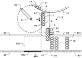
図3は、サンプラ部13、試料分注プローブ20、試料分注アーム21及び反応容器18の配置を示した平面図である。このサンプラ部13は、待機レーン80と、この待機レーン80の長手方向に対して長手方向が垂直になるように配置された分注レーン81とを備えている。   FIG. 3 is a plan view showing the arrangement of the sampler unit 13, the sample dispensing probe 20, the sample dispensing arm 21, and the reaction vessel 18. The sampler unit 13 includes a standby lane 80 and a dispensing lane 81 arranged so that the longitudinal direction is perpendicular to the longitudinal direction of the standby lane 80.

待機レーン80は、試料ラック12に保持された試料容器11内の試料の分注が可能な分注レーン81上へ試料ラック12を移動可能なように設けられている。そして、待機レーン80には、同一面上に分注待機エリア801及びこの分注待機エリア801に対して待機レーン80の長手方向の一方の方向である矢印L1に隣接する再分注待機エリア802が配設されている。   The standby lane 80 is provided so that the sample rack 12 can be moved onto a dispensing lane 81 where the sample in the sample container 11 held in the sample rack 12 can be dispensed. In the standby lane 80, the dispensing standby area 801 on the same plane and the re-dispensing standby area 802 adjacent to the dispensing standby area 801 adjacent to the arrow L 1 that is one of the longitudinal directions of the standby lane 80. Is arranged.

分注待機エリア801には、検査項目毎に1回目の分注が行われる試料が収容された試料容器11を保持する検査対象の試料ラック12が、この試料ラック12の短手方向が待機レーン80の長手方向に平行になるように載置される。また、再分注待機エリア802には、分注待機エリア801に載置された試料ラック12のうち、試料容器11内の試料の1回目の分注が行われた後、再検査のために2回目の分注が行われる試料が収容された試料容器11を保持する再検査対象の試料ラック12が保管される。   In the dispensing standby area 801, the sample rack 12 to be inspected that holds the sample container 11 containing the sample to be dispensed the first time for each inspection item, the short direction of the sample rack 12 is the standby lane. It is mounted so as to be parallel to the longitudinal direction of 80. Further, in the re-dispensing standby area 802, for the re-examination after the first dispensing of the sample in the sample container 11 among the sample racks 12 placed in the dispensing standby area 801 is performed. A sample rack 12 to be re-inspected for holding a sample container 11 containing a sample to be dispensed a second time is stored.

また、サンプラ部13は、待機レーン80上の分注待機エリア801に載置された各試料ラック12の位置を検出する位置検出器82と、待機レーン80上のラックID読み取り位置P1の各試料ラック12に記されているラックIDを読み取るラックIDリーダ83とを備えている。また、分注レーン81上の試料ラック12に保持された試料ID読み取り位置P3の試料容器11に記されている試料IDを読み取る試料IDリーダ84を備えている。また、再分注待機エリア802を識別可能なように点灯する待機レーン80上に配置されたLED85を備えている。そして、LED85のうち、再分注待機エリア802における待機レーン80長手方向の範囲85aが移動可能に点灯する。   The sampler unit 13 also includes a position detector 82 that detects the position of each sample rack 12 placed in the dispensing standby area 801 on the standby lane 80, and each sample at the rack ID reading position P 1 on the standby lane 80. A rack ID reader 83 that reads a rack ID written on the rack 12 is provided. Further, a sample ID reader 84 for reading the sample ID written on the sample container 11 at the sample ID reading position P3 held in the sample rack 12 on the dispensing lane 81 is provided. Moreover, it has LED85 arrange | positioned on the waiting lane 80 which lights so that the re-dispensing waiting area 802 can be identified. And among LED85, the range 85a of the waiting lane 80 longitudinal direction in the re-dispensing waiting area 802 lights so that a movement is possible.

なお、再分注待機エリア802は、保管する試料ラック12の数に応じて操作部60からの入力により範囲85aが変更可能なように配設される。   The re-dispensing standby area 802 is arranged so that the range 85a can be changed by an input from the operation unit 60 according to the number of sample racks 12 to be stored.

そして、待機レーン80上のすべての試料ラック12は、駆動部31の第1の移動機構311により、同じ速度で、同時に同じ方向のL1方向及びL1方向とは反対方向の矢印L2方向に移動される。また、待機レーン80上の引き込み位置P2の試料ラック12は、駆動部31の第2の移動機構312により、待機レーン80上からL1及びL2方向に対して垂直な矢印L3方向の分注レーン81上に移動される。また、分注レーン81上に移動された試料ラック12は、第2の移動機構312により、分注レーン81上でL1方向に移動される。また、分注レーン81上でL1方向に移動された試料ラック12は、第2の移動機構312により、L3方向とは反対方向の矢印L4方向の待機レーン80上に移動される。   Then, all the sample racks 12 on the standby lane 80 are simultaneously moved at the same speed by the first moving mechanism 311 of the driving unit 31 in the L1 direction in the same direction and the arrow L2 direction opposite to the L1 direction. The The sample rack 12 at the pull-in position P2 on the standby lane 80 is dispensed in the direction of the arrow L3 perpendicular to the L1 and L2 directions from the standby lane 80 by the second moving mechanism 312 of the drive unit 31. Moved up. Further, the sample rack 12 moved onto the dispensing lane 81 is moved in the L1 direction on the dispensing lane 81 by the second moving mechanism 312. Further, the sample rack 12 moved in the L1 direction on the dispensing lane 81 is moved by the second moving mechanism 312 onto the standby lane 80 in the direction of the arrow L4 opposite to the L3 direction.

分析制御部32は、予め設定された再検査条件、試料ID及びこの試料IDで識別される試料に設定された検査項目、位置検出器82により検出される各試料ラック12の位置情報、ラックIDリーダ83により読み取られるラックID、試料IDリーダ84により読み取られる試料ID、データ処理部40で生成される分析データ等に基づいて、待機レーン80上や分注レーン81上のすべての試料ラック12の移動を制御する。   The analysis control unit 32 includes a re-inspection condition set in advance, a sample ID, an inspection item set for the sample identified by the sample ID, position information of each sample rack 12 detected by the position detector 82, and a rack ID. Based on the rack ID read by the reader 83, the sample ID read by the sample ID reader 84, the analysis data generated by the data processing unit 40, etc., all the sample racks 12 on the standby lane 80 and the dispensing lane 81 are displayed. Control movement.

そして、待機レーン80上の分注待機エリア801に載置される試料ラック12を分注レーン81上へ移動させて、当該試料ラック12に保持された試料容器11内の試料を分注させ、当該試料ラック12に保持された試料容器11内の試料の分注が終了すると、分注待機エリア801に移動させ、当該試料容器11内の試料及び試薬の混合液の測定により生成された分析データが予め設定された再検査条件に当てはまるデータである場合に当該試料ラック12を分注待機エリア801から分注レーン81を経由させて待機レーン80上の再分注待機エリア802へ移動させる。   Then, the sample rack 12 placed in the dispensing standby area 801 on the standby lane 80 is moved onto the dispensing lane 81 to dispense the sample in the sample container 11 held in the sample rack 12, When dispensing of the sample in the sample container 11 held in the sample rack 12 is completed, the sample is moved to the dispensing standby area 801, and analysis data generated by measuring the mixed solution of the sample and the reagent in the sample container 11 is obtained. Is the data that satisfies the preset re-inspection conditions, the sample rack 12 is moved from the dispensing standby area 801 to the re-dispensing standby area 802 on the standby lane 80 via the dispensing lane 81.

また、待機レーン80上の分注待機エリア801に載置される試料ラック12を分注レーン81上へ移動させて、当該試料ラック12に保持された試料容器11内の試料を分注させ、当該試料の分注に係る異常が検出された場合、当該試料ラック12を分注レーン81から待機レーン80上の再分注待機エリア802へ移動させる。   Further, the sample rack 12 placed in the dispensing standby area 801 on the standby lane 80 is moved onto the dispensing lane 81 so that the sample in the sample container 11 held by the sample rack 12 is dispensed. When an abnormality relating to the dispensing of the sample is detected, the sample rack 12 is moved from the dispensing lane 81 to the re-dispensing waiting area 802 on the waiting lane 80.

以下、図1乃至図15を参照して、自動分析装置100の動作の一例について説明する。   Hereinafter, an example of the operation of the automatic analyzer 100 will be described with reference to FIGS. 1 to 15.

操作部60から検査を行う試料毎に試料IDの入力及び検査項目を設定するための入力が行われた後、検査開始の入力が行われると、システム制御部70は、分析制御部32、データ処理部40及び出力部50に検査開始の指示をする。分析制御部32は、駆動部31を制御して分析部10の各種ユニットを作動させる。   After inputting the sample ID and setting the inspection item for each sample to be inspected from the operation unit 60, the system control unit 70, the analysis control unit 32, the data The processing unit 40 and the output unit 50 are instructed to start inspection. The analysis control unit 32 controls the drive unit 31 to operate various units of the analysis unit 10.

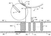
分析部10におけるサンプラ部13のLED85は、図4に示すように、待機レーン80上の例えばラックID読み取り位置P1を端部として分注待機エリア801に隣接する再分注待機エリア802の範囲85aが点灯する。そして、入力された試料IDの試料が収容された試料容器11を保持する検査対象のN個の試料ラック12が待機レーン80上の分注待機エリア801に載置される。   As shown in FIG. 4, the LED 85 of the sampler unit 13 in the analysis unit 10 includes a range 85 a of a re-dispensing standby area 802 adjacent to the dispensing standby area 801 with, for example, a rack ID reading position P1 on the standby lane 80 as an end. Lights up. Then, the N sample racks 12 to be inspected that hold the sample container 11 in which the sample of the input sample ID is stored are placed in the dispensing standby area 801 on the standby lane 80.

位置検出器82は、N個の試料ラック12が載置された分注待機エリア801の位置を検出する。駆動部31の第1の移動機構311は、図4に示すように、位置が検出されたN個の試料ラック12をL1方向に移動する。分析制御部32は、LED85の点灯している範囲85aを、待機レーン80上の各試料ラック12と同じ速度で同じ方向に移動させる。   The position detector 82 detects the position of the dispensing standby area 801 where the N sample racks 12 are placed. As shown in FIG. 4, the first moving mechanism 311 of the drive unit 31 moves the N sample racks 12 whose positions are detected in the L1 direction. The analysis control unit 32 moves the range 85 a in which the LED 85 is lit in the same direction at the same speed as each sample rack 12 on the standby lane 80.

ラックIDリーダ83は、L1方向への移動により、ラックID読み取り位置P1に到達する1番目の試料ラック12のラックIDを読み取る。第1の移動機構311は、ラックIDが読み取られた1番目の試料ラック12が引き込み位置P2に到達するまで分注待機エリア801の各試料ラック12をL1方向に移動する。分析制御部32は、LED85の点灯している範囲85aを、待機レーン80上の各試料ラック12と同じ速度で同じ方向に移動させる。   The rack ID reader 83 reads the rack ID of the first sample rack 12 that reaches the rack ID reading position P1 by moving in the L1 direction. The first moving mechanism 311 moves each sample rack 12 in the dispensing standby area 801 in the L1 direction until the first sample rack 12 whose rack ID has been read reaches the pull-in position P2. The analysis control unit 32 moves the range 85 a in which the LED 85 is lit in the same direction at the same speed as each sample rack 12 on the standby lane 80.

第2の移動機構312は、図5に示すように、引き込み位置P2の1番目の試料ラック12を待機レーン80上から分注レーン81上に移動する。試料IDリーダ84は、待機レーン80上から分注レーン81上に移動されている1番目の試料ラック12に保持された試料ID読み取り位置P3の各試料容器11の試料IDを読み取る。ラックIDリーダ83は、ラックID読み取り位置P1の2番目の試料ラック12のラックIDを読み取る。   As shown in FIG. 5, the second moving mechanism 312 moves the first sample rack 12 at the drawing position P <b> 2 from the standby lane 80 to the dispensing lane 81. The sample ID reader 84 reads the sample ID of each sample container 11 at the sample ID reading position P3 held in the first sample rack 12 moved from the standby lane 80 to the dispensing lane 81. The rack ID reader 83 reads the rack ID of the second sample rack 12 at the rack ID reading position P1.

第2の移動機構312は、試料IDが読み取られた分注レーン81上の1番目の試料ラック12を1個分、分注レーン81上でL1方向に移動する。第1の移動機構311は、分注待機エリア801の(N−1)個の試料ラック12を試料ラック12の1個分、L1方向に移動する。分析制御部32は、LED85の点灯している範囲85aを、待機レーン80上の各試料ラック12と同じ速度で同じ方向に移動させる。   The second moving mechanism 312 moves one first sample rack 12 on the dispensing lane 81 from which the sample ID has been read, on the dispensing lane 81 in the L1 direction. The first moving mechanism 311 moves (N−1) sample racks 12 in the dispensing standby area 801 by one sample rack 12 in the L1 direction. The analysis control unit 32 moves the range 85 a in which the LED 85 is lit in the same direction at the same speed as each sample rack 12 on the standby lane 80.

第2の移動機構312は、図6に示すように、引き込み位置P2の2番目の試料ラック12を待機レーン80上から分注レーン81上に移動する。試料IDリーダ84は、待機レーン80上から分注レーン81上に移動されている2番目の試料ラック12に保持された試料ID読み取り位置P3の各試料容器11の試料IDを読み取る。ラックIDリーダ83は、ラックID読み取り位置P1の3番目の試料ラック12のラックIDを読み取る。   As shown in FIG. 6, the second moving mechanism 312 moves the second sample rack 12 at the pull-in position P <b> 2 from the standby lane 80 to the dispensing lane 81. The sample ID reader 84 reads the sample ID of each sample container 11 at the sample ID reading position P3 held in the second sample rack 12 moved from the standby lane 80 to the dispensing lane 81. The rack ID reader 83 reads the rack ID of the third sample rack 12 at the rack ID reading position P1.

試料分注プローブ20は、分注レーン81上の1番目の試料ラック12に保持される吸引位置P4の試料容器11内の試料を分注する。第2の移動機構312は、吸引位置P4における試料容器11内の試料の分注終了毎に1番目の試料ラック12を試料容器11の1個分、L4方向に移動する。   The sample dispensing probe 20 dispenses the sample in the sample container 11 at the suction position P4 held by the first sample rack 12 on the dispensing lane 81. The second moving mechanism 312 moves the first sample rack 12 by one sample container 11 in the L4 direction every time the dispensing of the sample in the sample container 11 at the suction position P4 is completed.

第2の移動機構312は、1番目の試料ラック12に保持されたすべての試料容器11内の試料の分注が終了すると、図7に示すように、1番目の試料ラック12を分注レーン81上から待機レーン80上の分注待機エリア801における1番目の試料ラック12が載置された位置へ移動する。   When the dispensing of the samples in all the sample containers 11 held in the first sample rack 12 is completed, the second moving mechanism 312 moves the first sample rack 12 into the dispensing lane as shown in FIG. Move from 81 to the position where the first sample rack 12 is placed in the dispensing standby area 801 on the standby lane 80.

第2の移動機構312は、試料IDが読み取られた2番目の試料ラック12を試料ラック12の1個分、分注レーン81上でL1方向に移動する。第1の移動機構311は、待機レーン80上の(N−1)個の試料ラック12を試料ラック12の1個分、L1方向に移動する。分析制御部32は、LED85の点灯している範囲85aを、待機レーン80上の各試料ラック12と同じ速度で同じ方向に移動させる。   The second moving mechanism 312 moves the second sample rack 12 from which the sample ID has been read by one sample rack 12 on the dispensing lane 81 in the L1 direction. The first moving mechanism 311 moves (N−1) sample racks 12 on the standby lane 80 by one sample rack 12 in the L1 direction. The analysis control unit 32 moves the range 85 a in which the LED 85 is lit in the same direction at the same speed as each sample rack 12 on the standby lane 80.

第2の移動機構312は、図8に示すように、引き込み位置P2の3番目の試料ラック12を待機レーン80上から分注レーン81上に移動する。試料IDリーダ84は、待機レーン80上から分注レーン81上に移動されている3番目の試料ラック12に保持された試料ID読み取り位置P3の各試料容器11の試料IDを読み取る。ラックIDリーダ83は、ラックID読み取り位置P1の4番目の試料ラック12のラックIDを読み取る。   As shown in FIG. 8, the second moving mechanism 312 moves the third sample rack 12 at the pull-in position P <b> 2 from the standby lane 80 to the dispensing lane 81. The sample ID reader 84 reads the sample ID of each sample container 11 at the sample ID reading position P3 held in the third sample rack 12 moved from the standby lane 80 to the dispensing lane 81. The rack ID reader 83 reads the rack ID of the fourth sample rack 12 at the rack ID reading position P1.

試料分注プローブ20は、分注レーン81上の2番目の試料ラック12に保持される吸引位置P4の試料容器11内の試料を分注する。第2の移動機構312は、吸引位置P4における試料容器11内の試料の分注終了毎に2番目の試料ラック12を試料容器11の1個分、L4方向に移動する。   The sample dispensing probe 20 dispenses the sample in the sample container 11 at the suction position P4 held by the second sample rack 12 on the dispensing lane 81. The second moving mechanism 312 moves the second sample rack 12 in the L4 direction by one sample container 11 each time the dispensing of the sample in the sample container 11 at the suction position P4 is completed.

第2の移動機構312は、2番目の試料ラック12に保持されたすべての試料容器11内の試料の分注が終了すると、2番目の試料ラック12を、図9に示すように、分注レーン81上から待機レーン80上の載置された位置へ移動する。   When the dispensing of the samples in all the sample containers 11 held by the second sample rack 12 is completed, the second moving mechanism 312 dispenses the second sample rack 12 as shown in FIG. It moves from the lane 81 to the placed position on the standby lane 80.

第2の移動機構312は、試料IDが読み取られた3番目の試料ラック12を1個分、分注レーン81上でL1方向に移動する。第1の移動機構311は、待機レーン80上の各試料ラック12を1個分、L1方向に移動する。分析制御部32は、LED85の点灯している範囲85aを、待機レーン80上の各試料ラック12と同じ速度で同じ方向に移動させる。   The second moving mechanism 312 moves one third sample rack 12 from which the sample ID has been read on the dispensing lane 81 in the L1 direction. The first moving mechanism 311 moves one sample rack 12 on the standby lane 80 by one in the L1 direction. The analysis control unit 32 moves the range 85 a in which the LED 85 is lit in the same direction at the same speed as each sample rack 12 on the standby lane 80.

試料分注プローブ20は、分注レーン81上の3番目の試料ラック12に保持される吸引位置P4の試料容器11内の試料を分注する。第2の移動機構312は、吸引位置P4における試料容器11内の試料の分注終了毎に3番目の試料ラック12を試料容器11の1個分、L4方向に移動する。   The sample dispensing probe 20 dispenses the sample in the sample container 11 at the suction position P4 held by the third sample rack 12 on the dispensing lane 81. The second moving mechanism 312 moves the third sample rack 12 by one sample container 11 in the L4 direction every time the dispensing of the sample in the sample container 11 at the suction position P4 is completed.

第2の移動機構312は、3番目の試料ラック12に保持されたすべての試料容器11内の試料の分注が終了すると、3番目の試料ラック12を待機レーン80上の分注待機エリア801における3番目の試料ラック12が載置された位置へ移動する。   When the dispensing of the samples in all the sample containers 11 held in the third sample rack 12 is completed, the second moving mechanism 312 moves the third sample rack 12 to the dispensing standby area 801 on the standby lane 80. To the position where the third sample rack 12 is placed.

第1及び第2の移動機構311,312は、1乃至3番目の試料ラック12の場合と同様にして4番目以降の(N−3)個の試料ラック12を移動する。また、ラックIDリーダ83は、1乃至3番目の試料ラック12の場合と同様にして4番目以降の(N−3)個の試料ラック12のラックIDを読み取る。また、試料IDリーダ84は、1乃至3番目の試料ラック12の場合と同様にして4番目以降の(N−3)個の試料ラック12に保持された試料容器11の試料IDを読み取る。また、試料分注プローブ20は、1乃至3番目の試料ラック12の場合と同様にして4番目以降の(N−3)個の試料ラック12に保持された試料容器11の試料の分注を行う。   The first and second moving mechanisms 311 and 312 move the fourth and subsequent (N−3) sample racks 12 in the same manner as the first to third sample racks 12. The rack ID reader 83 reads the rack IDs of the fourth and subsequent (N-3) sample racks 12 in the same manner as the first to third sample racks 12. The sample ID reader 84 reads the sample IDs of the sample containers 11 held in the fourth and subsequent (N-3) sample racks 12 in the same manner as the first to third sample racks 12. The sample dispensing probe 20 dispenses the sample in the sample container 11 held in the fourth and subsequent (N-3) sample racks 12 in the same manner as in the first to third sample racks 12. Do.

第2の移動機構312は、N番目の試料ラック12に保持されたすべての試料容器11内の試料の分注が終了すると、図10に示すように、分注レーン81上のN番目の試料ラック12を待機レーン80上の分注待機エリア801におけるN番目の試料ラック12が載置された位置へ移動する。   When the dispensing of the samples in all the sample containers 11 held in the Nth sample rack 12 is completed, the second moving mechanism 312, as shown in FIG. 10, the Nth sample on the dispensing lane 81. The rack 12 is moved to the position where the Nth sample rack 12 is placed in the dispensing standby area 801 on the standby lane 80.

N個の試料ラック12に保持された試料容器11内の試料の分注により、データ処理部40ですべての分析データが生成された後、分析制御部32は、データ処理部40で生成された分析データの中に再検査条件に当てはまる分析データが含まれていない場合、分析部10のすべてのユニットの動作を終了させる。また、データ処理部40で生成された分析データの中に再検査条件に当てはまる分析データが含まれている場合、再検査条件に当てはまる分析データが生成された試料を収容する試料容器11が保持された再検査対象の試料ラック12を、待機レーン80上の分注待機エリア801から再分注待機エリア802に移動させる。   After all the analysis data is generated by the data processing unit 40 by dispensing the samples in the sample containers 11 held in the N sample racks 12, the analysis control unit 32 is generated by the data processing unit 40. If the analysis data does not include analysis data that meets the reinspection conditions, the operation of all the units of the analysis unit 10 is terminated. In addition, when the analysis data generated by the data processing unit 40 includes analysis data that meets the reinspection conditions, the sample container 11 that holds the sample in which the analysis data that meets the reinspection conditions is generated is held. The sample rack 12 to be re-inspected is moved from the dispensing standby area 801 on the standby lane 80 to the re-dispensing standby area 802.

ここで、例えば再検査パラメータとして設定された閾値を外れる分析データが生成された試料を収容する試料容器11が保持された1番目と3番目の試料ラック12を、分注待機エリア801から再分注待機エリア802に移動させる場合の一例について説明する。   Here, for example, the first and third sample racks 12 holding the sample containers 11 that store the samples for which the analysis data that deviates from the threshold value set as the reinspection parameter are redistributed from the dispensing standby area 801. Note An example of moving to the standby area 802 will be described.

N番目の試料ラック12が分注待機エリア801に移動された後、第1の移動機構311は、例えば3番目の試料ラック12が引き込み位置P2に到達するまで分注待機エリア801のN個の試料ラック12をL2方向へ移動する。分析制御部32は、LED85の点灯している範囲85aを、待機レーン80上の各試料ラック12と同じ速度で同じ方向に移動させる。   After the N-th sample rack 12 is moved to the dispensing standby area 801, the first moving mechanism 311 moves the N number of samples in the dispensing standby area 801 until, for example, the third sample rack 12 reaches the drawing position P2. The sample rack 12 is moved in the L2 direction. The analysis control unit 32 moves the range 85 a in which the LED 85 is lit in the same direction at the same speed as each sample rack 12 on the standby lane 80.

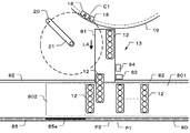
第2の移動機構312は、引き込み位置P2へ移動された3番目の試料ラック12を、図11に示すように、待機レーン80上から分注レーン81上に移動する。次いで、分注レーン81上に移動した試料ラック12を分注レーン81上でL1方向に移動する。第1の移動機構311は、3番目の試料ラック12が分注レーン81上に移動された後、1番目の試料ラック12が引き込み位置P2に到達するまで分注待機エリア801の(N−1)個の試料ラック12をL2方向へ移動する。分析制御部32は、LED85の点灯している範囲85aを、待機レーン80上の各試料ラック12と同じ速度で同じ方向に移動させる。   The second moving mechanism 312 moves the third sample rack 12 moved to the pull-in position P2 from the standby lane 80 to the dispensing lane 81 as shown in FIG. Next, the sample rack 12 that has moved onto the dispensing lane 81 moves on the dispensing lane 81 in the L1 direction. After the third sample rack 12 has been moved onto the dispensing lane 81, the first moving mechanism 311 has (N−1) in the dispensing standby area 801 until the first sample rack 12 reaches the drawing position P2. ) Move the sample racks 12 in the L2 direction. The analysis control unit 32 moves the range 85 a in which the LED 85 is lit in the same direction at the same speed as each sample rack 12 on the standby lane 80.

第2の移動機構312は、分注レーン81上でL1方向に移動した3番目の試料ラック12を、図12に示すように、分注レーン81上から待機レーン80上の再分注待機エリア802に移動する。また、引き込み位置P2の1番目の試料ラック12を、待機レーン80上から分注レーン81上のへ移動する。次いで、分注レーン81上でL1方向に移動する。   The second moving mechanism 312 moves the third sample rack 12 moved in the L1 direction on the dispensing lane 81 from the dispensing lane 81 to the re-dispensing waiting area on the waiting lane 80 as shown in FIG. Move to 802. Further, the first sample rack 12 at the pull-in position P2 is moved from the waiting lane 80 to the dispensing lane 81. Subsequently, it moves in the L1 direction on the dispensing lane 81.

なお、分注レーン81上の再検査対象の試料を収容する試料容器11が吸引位置P4に到達する位置で3番目の試料ラック12を停止させ、試料分注プローブ20により、再検査対象の検査項目の試料を分注させるように実施してもよい。   The third sample rack 12 is stopped at the position where the sample container 11 containing the sample to be reinspected on the dispensing lane 81 reaches the suction position P4, and the sample to be reinspected is inspected by the sample dispensing probe 20. You may carry out so that the sample of an item may be dispensed.

第2の移動機構312は、分注レーン81上に移動した1番目の試料ラック12を分注レーン81上でL1方向に移動する。第1の移動機構311は、待機レーン80上の(N−1)個の試料ラック12を1個分、L2方向に移動する。分析制御部32は、LED85の点灯している範囲85aを、待機レーン80上の各試料ラック12と同じ速度で同じ方向に移動させる。   The second moving mechanism 312 moves the first sample rack 12 moved onto the dispensing lane 81 in the L1 direction on the dispensing lane 81. The first moving mechanism 311 moves (N−1) sample racks 12 on the standby lane 80 by one in the L2 direction. The analysis control unit 32 moves the range 85 a in which the LED 85 is lit in the same direction at the same speed as each sample rack 12 on the standby lane 80.

第2の移動機構312は、分注レーン81上でL1方向に移動した1番目の試料ラック12を、図13に示すように、分注レーン81上から待機レーン80上の再分注待機エリア802に移動する。   The second moving mechanism 312 moves the first sample rack 12 moved in the L1 direction on the dispensing lane 81 from the dispensing lane 81 to the re-dispensing waiting area on the waiting lane 80 as shown in FIG. Move to 802.

なお、分注レーン81上の再検査対象の試料を収容する試料容器11が吸引位置P4に到達する位置で1番目の試料ラック12を停止させ、試料分注プローブ20により、再検査対象の検査項目の試料を分注させるように実施してもよい。   The first sample rack 12 is stopped at the position where the sample container 11 containing the sample to be reinspected on the dispensing lane 81 reaches the suction position P4, and the sample to be reinspected is inspected by the sample dispensing probe 20. You may carry out so that the sample of an item may be dispensed.

第1の移動機構311は、待機レーン80上の再分注待機エリア802に保管された1番目及び3番目の試料ラック12並びに分注待機エリア801の(N−2)個の試料ラック12をL2方向に移動し、図14に示すように、再分注開始位置である例えば1番目の試料ラック12がラックID読み取り位置P1に到達する位置で停止させる。分析制御部32は、LED85の点灯している範囲85aを待機レーン80上の各試料ラック12と同じ速度で同じ方向に移動させる。分析制御部32は、LED85の点灯している範囲85aを、待機レーン80上の各試料ラック12と同じ速度で同じ方向に移動させ、待機レーン80上の各試料ラック12が停止するタイミングで停止させる。   The first moving mechanism 311 stores the first and third sample racks 12 stored in the re-dispensing standby area 802 on the standby lane 80 and the (N-2) sample racks 12 in the dispensing standby area 801. As shown in FIG. 14, the sample is moved in the L2 direction and stopped at a position where the re-dispensing start position, for example, the first sample rack 12 reaches the rack ID reading position P1. The analysis control unit 32 moves the range 85 a in which the LED 85 is lit in the same direction at the same speed as each sample rack 12 on the standby lane 80. The analysis control unit 32 moves the range 85a in which the LED 85 is lit in the same direction as each sample rack 12 on the standby lane 80 in the same direction, and stops when each sample rack 12 on the standby lane 80 stops. Let

このように、再検査対象の試料ラック12を、この試料ラック12が載置された待機レーン80上の分注待機エリア801から、待機レーン80上の再分注待機エリア802に移動させることができる。また、再分注待機エリア802の範囲85aを点灯させることにより、再分注待機エリア802に移動された再検査対象の試料ラック12を容易に見分けることができる。   In this way, the sample rack 12 to be re-inspected can be moved from the dispensing standby area 801 on the standby lane 80 where the sample rack 12 is placed to the re-dispensing standby area 802 on the standby lane 80. it can. In addition, by lighting the range 85a of the re-dispensing standby area 802, the sample rack 12 to be re-inspected that has been moved to the re-dispensing standby area 802 can be easily identified.

ここで、操作部60から再検開始の入力が行われると、第1の移動機構311は、再分注開始位置から1番目の試料ラック12が引き込み位置P2に到達する位置まで待機レーン80上のN個の試料ラック12をL1方向に移動する。第2の移動機構312は、1番目の試料ラック12を待機レーン80上から分注レーン81上の再検査対象の試料を収容する試料容器11が吸引位置P4に到達する位置まで移動する。試料分注プローブ20は、吸引位置P4の試料容器11内の再検査対象の検査項目の試料を分注する。再検査の試料の分注が終了すると、1番目の試料ラック12を分注レーン81上から待機レーン80上の再分注待機エリア802における最初に移動された位置へ移動する。   Here, when the retest start is input from the operation unit 60, the first moving mechanism 311 moves on the standby lane 80 from the redispensing start position to the position where the first sample rack 12 reaches the drawing position P2. The N sample racks 12 are moved in the L1 direction. The second moving mechanism 312 moves the first sample rack 12 from the standby lane 80 to a position where the sample container 11 containing the sample to be retested on the dispensing lane 81 reaches the suction position P4. The sample dispensing probe 20 dispenses the sample of the inspection item to be reinspected in the sample container 11 at the suction position P4. When dispensing of the sample for reinspection is completed, the first sample rack 12 is moved from the dispensing lane 81 to the first moved position in the redispensing waiting area 802 on the waiting lane 80.

また、第1の移動機構311は、3番目の試料ラック12が引き込み位置P2に到達する位置まで待機レーン80上のN個の試料ラック12をL1方向に移動する。第2の移動機構312は、3番目の試料ラック12を待機レーン80上から、分注レーン81上の再検査対象の試料を収容する試料容器11が吸引位置P4に到達する位置まで移動する。試料分注プローブ20は、吸引位置P4の試料容器11内の再検査対象の検査項目の試料を分注する。   The first moving mechanism 311 moves the N sample racks 12 on the standby lane 80 in the L1 direction to a position where the third sample rack 12 reaches the pull-in position P2. The second moving mechanism 312 moves the third sample rack 12 from the standby lane 80 to a position where the sample container 11 containing the sample to be retested on the dispensing lane 81 reaches the suction position P4. The sample dispensing probe 20 dispenses the sample of the inspection item to be reinspected in the sample container 11 at the suction position P4.

再検査対象の試料の分注が終了すると、3番目の試料ラック12を分注レーン81上から待機レーン80上の再分注待機エリア802における最初に移動された位置へ移動する。第1の移動機構311は、待機レーン80上の再分注待機エリア802に戻された1番目及び3番目の試料ラック12並びに分注待機エリア801の(N−2)個の試料ラック12を1個分、L1方向に移動した再分注終了位置で停止させる。分析制御部32は、LED85の点灯している範囲85aを、待機レーン80上の各試料ラック12と同じ速度で同じ方向に移動させ、待機レーン80上の各試料ラック12が停止するタイミングで停止させる。   When the dispensing of the sample to be retested is completed, the third sample rack 12 is moved from the dispensing lane 81 to the first moved position in the redispensing waiting area 802 on the waiting lane 80. The first moving mechanism 311 moves the first and third sample racks 12 returned to the re-dispensing waiting area 802 on the waiting lane 80 and the (N−2) sample racks 12 in the dispensing waiting area 801. Stop at the re-dispensing end position moved by one in the L1 direction. The analysis control unit 32 moves the range 85a in which the LED 85 is lit in the same direction as each sample rack 12 on the standby lane 80 in the same direction, and stops when each sample rack 12 on the standby lane 80 stops. Let

そして、2回目の試料の分注により、データ処理部40で再検データが生成され、出力部50から出力されると、システム制御部70が分析制御部32、データ処理部40及び出力部50に検査終了の指示をすることにより、自動分析装置100は動作を終了する。   Then, when the retest data is generated by the data processing unit 40 and output from the output unit 50 by the second sample dispensing, the system control unit 70 sends the analysis control unit 32, the data processing unit 40, and the output unit 50. By instructing the end of the inspection, the automatic analyzer 100 ends the operation.

以上述べた実施形態によれば、検査対象の試料ラック12を分注レーン81に移動可能なように設けた待機レーン80上に、再検査対象の試料ラック12を保管可能な再分注待機エリア802を設けることにより、1回目の試料の分注を終えた再検査の可能性がある試料ラック12を一時的に保管する保管場所を設ける必要がないため、分析部10の大型化を防ぐことができる。また、一時保管場所まで搬送する搬送ラインを必要としないため分析部10の大型化を防ぐことができる。   According to the embodiment described above, the redispensing standby area in which the sample rack 12 to be retested can be stored on the standby lane 80 provided so that the sample rack 12 to be tested can be moved to the dispensing lane 81. By providing 802, it is not necessary to provide a storage place for temporarily storing the sample rack 12 that may be re-inspected after the first sample is dispensed. Can do. Moreover, since the conveyance line which conveys to a temporary storage place is not required, the enlargement of the analysis part 10 can be prevented.

本発明のいくつかの実施形態を説明したが、これらの実施形態は、例として提示したものであり、発明の範囲を限定することを意図していない。これら新規な実施形態は、その他の様々な形態で実施されることが可能であり、発明の要旨を逸脱しない範囲で、種々の省略、置き換え、変更を行うことができる。これら実施形態やその変形は、発明の範囲や要旨に含まれると共に、特許請求の範囲に記載された発明とその均等の範囲に含まれる。   Although several embodiments of the present invention have been described, these embodiments are presented by way of example and are not intended to limit the scope of the invention. These novel embodiments can be implemented in various other forms, and various omissions, replacements, and changes can be made without departing from the scope of the invention. These embodiments and modifications thereof are included in the scope and gist of the invention, and are included in the invention described in the claims and the equivalents thereof.

11 試料容器
12 試料ラック
13 サンプラ部
18 反応容器
20 試料分注プローブ
32 分析制御部
80 待機レーン
81 分注レーン
311 第1の移動機構
312 第2の移動機構
801 分注待機エリア
802 再分注待機エリア
11 Sample container 12 Sample rack 13 Sampler unit 18 Reaction vessel 20 Sample dispensing probe 32 Analysis control unit 80 Standby lane 81 Dispensing lane 311 First moving mechanism 312 Second moving mechanism 801 Dispensing standby area 802 Redispensing standby area

Claims (10)

試料及び試薬を反応容器に分注して、前記反応容器内の試料及び試薬の混合液を測定する自動分析装置において、
試料ラックに保持された試料容器内の試料の分注が可能な分注レーン上へ前記試料ラックを移動可能なように設けた待機レーンと、
前記待機レーン上の前記試料ラックを移動する第1の移動機構と、
前記待機レーン又は前記分注レーンのいずれか一方のレーン上の前記試料ラックを他方のレーン上へ移動する第2の移動機構と、
前記待機レーン上に配設された分注待機エリアに載置される前記試料ラックを前記分注レーン上へ移動させて、当該試料ラックに保持された試料容器内の試料を分注させ、当該試料の分注に係る異常が検出された場合、又は当該試料及び前記試薬の混合液の測定により生成された分析データが予め設定された再検査条件に当てはまるデータである場合、当該試料ラックを前記待機レーン上に配設された再分注待機エリアへ移動させる分析制御部と、
を備える自動分析装置。
In an automatic analyzer that dispenses a sample and a reagent into a reaction container and measures a mixed solution of the sample and the reagent in the reaction container,
A standby lane provided so that the sample rack can be moved onto a dispensing lane capable of dispensing the sample in the sample container held in the sample rack;
A first moving mechanism for moving the sample rack on the waiting lane;
A second moving mechanism for moving the sample rack on one of the waiting lane or the dispensing lane onto the other lane;
The sample rack placed in the dispensing standby area arranged on the waiting lane is moved onto the dispensing lane, and the sample in the sample container held in the sample rack is dispensed, and the When abnormality relating to the dispensing of the sample is detected, or when the analysis data generated by the measurement of the mixed solution of the sample and the reagent is data that meets preset retest conditions, the sample rack is An analysis control unit that moves to a re-dispensing waiting area arranged on the waiting lane;
An automatic analyzer comprising:
前記再分注待機エリアは、前記分注待機エリアに対して前記待機レーンの長手方向における一方の方向に配設され、
前記第1の移動機構は、前記待機レーン上の前記試料ラックを前記長手方向に移動する請求項1に記載の自動分析装置。
The re-dispensing standby area is disposed in one direction in the longitudinal direction of the standby lane with respect to the dispensing standby area,
The automatic analyzer according to claim 1, wherein the first moving mechanism moves the sample rack on the waiting lane in the longitudinal direction.
前記第1の移動機構は、前記待機レーン上のすべての前記試料ラックを同じ速度で同じ方向に移動する請求項1又は請求項2に記載の自動分析装置。   The automatic analyzer according to claim 1, wherein the first moving mechanism moves all the sample racks on the waiting lane in the same direction at the same speed. 前記再分注待機エリア及び前記分注待機エリアは、前記待機レーンの同一面上に配設されている請求項1乃至請求項3のいずれかに記載の自動分析装置。   The automatic analyzer according to any one of claims 1 to 3, wherein the re-dispensing standby area and the dispensing standby area are disposed on the same surface of the standby lane. 前記再分注待機エリアは、前記待機レーンの長手方向における範囲が識別可能に配設されている請求項1乃至請求項4のいずれかに記載の自動分析装置。   The automatic analyzer according to any one of claims 1 to 4, wherein the re-dispensing standby area is disposed so that a range in a longitudinal direction of the standby lane can be identified. 前記再分注待機エリアは、前記待機レーンの長手方向における範囲が変更可能に配設されている請求項1乃至請求項5のいずれかに記載の自動分析装置。   The automatic analyzer according to any one of claims 1 to 5, wherein the re-dispensing standby area is arranged such that a range in a longitudinal direction of the standby lane can be changed. 前記分析制御部は、前記分注待機エリアに載置される前記試料ラックを前記分注レーン上へ移動させて、当該試料ラックに保持された試料容器内の試料の分注が終了すると前記分注待機エリアに移動させ、当該試料容器内の試料及び前記試薬の混合液の測定により生成された分析データが予め設定された再検査条件に当てはまるデータである場合、当該試料ラックを前記分注待機エリアから前記分注レーン上に移動させ、前記分注レーン上に移動させた当該試料ラックを前記再分注待機エリアへ移動させる請求項1乃至請求項6のいずれかに記載の自動分析装置。   The analysis control unit moves the sample rack placed in the dispensing standby area onto the dispensing lane, and finishes dispensing the sample in the sample container held in the sample rack. When the analysis data generated by measuring the sample in the sample container and the mixed solution of the reagent is the data that meets the preset re-inspection conditions, move the sample rack to the dispensing standby area. The automatic analyzer according to any one of claims 1 to 6, wherein the sample rack moved from an area onto the dispensing lane and moved onto the dispensing lane is moved to the re-dispensing standby area. 前記分析制御部は、前記分注待機エリアに載置される前記試料ラックを前記分注レーン上へ移動させて、当該試料ラックに保持された試料容器内の試料を分注させ、当該試料及び前記試薬の混合液の測定により生成された分析データが予め設定された閾値を超えている場合、当該試料ラックを前記再分注待機エリアへ移動させる請求項1乃至請求項7のいずれかに記載の自動分析装置。   The analysis control unit moves the sample rack placed in the dispensing standby area onto the dispensing lane, dispenses the sample in the sample container held in the sample rack, 8. The sample rack is moved to the re-dispensing standby area when analysis data generated by measurement of the reagent mixture exceeds a preset threshold value. 9. Automatic analyzer. 前記分析制御部は、前記分注待機エリアに載置される前記試料ラックを前記分注レーン上へ移動させて、当該試料ラックに保持された試料容器内の試料の分注が終了すると前記分注待機エリアに移動させ、当該試料及び前記試薬の混合液の測定により生成された分析データが予め設定された閾値を超えている場合、当該試料ラックを前記分注待機エリアから前記再分注待機エリアへ移動させる請求項8に記載の自動分析装置。   The analysis control unit moves the sample rack placed in the dispensing standby area onto the dispensing lane, and finishes dispensing the sample in the sample container held in the sample rack. When the analysis data generated by moving the sample to the injection standby area and measuring the mixed solution of the sample and the reagent exceeds a preset threshold, the sample rack is moved from the dispensing standby area to the re-dispense standby. The automatic analyzer according to claim 8, which is moved to an area. 前記分析制御部は、前記分注待機エリアに載置される前記試料ラックを前記分注レーン上へ移動させて、当該試料ラックに保持された試料容器内の試料を分注させ、当該試料の分注に係る異常が検出された場合、当該試料ラックを前記分注レーンから前記再分注待機エリアへ移動させる請求項1に記載の自動分析装置。   The analysis control unit moves the sample rack placed in the dispensing standby area onto the dispensing lane, causes the sample in the sample container held in the sample rack to be dispensed, and The automatic analyzer according to claim 1, wherein when an abnormality related to dispensing is detected, the sample rack is moved from the dispensing lane to the re-dispensing standby area.
JP2016036171A 2016-02-26 2016-02-26 Automatic analyzer Active JP6675226B2 (en)

Priority Applications (1)

Application Number Priority Date Filing Date Title
JP2016036171A JP6675226B2 (en) 2016-02-26 2016-02-26 Automatic analyzer

Applications Claiming Priority (1)

Application Number Priority Date Filing Date Title
JP2016036171A JP6675226B2 (en) 2016-02-26 2016-02-26 Automatic analyzer

Publications (2)

Publication Number Publication Date
JP2017151054A true JP2017151054A (en) 2017-08-31
JP6675226B2 JP6675226B2 (en) 2020-04-01

Family

ID=59739701

Family Applications (1)

Application Number Title Priority Date Filing Date
JP2016036171A Active JP6675226B2 (en) 2016-02-26 2016-02-26 Automatic analyzer

Country Status (1)

Country Link
JP (1) JP6675226B2 (en)

Cited By (1)

* Cited by examiner, † Cited by third party
Publication number Priority date Publication date Assignee Title
US20210255210A1 (en) * 2018-10-23 2021-08-19 Sekisui Medical Co., Ltd. Autosampler, automatic analysis device, sampling method, and automatic inspection method

Citations (7)

* Cited by examiner, † Cited by third party
Publication number Priority date Publication date Assignee Title
JPH0572215A (en) * 1991-09-13 1993-03-23 Toshiba Corp Automatic apparatus for chemical analysis
JPH09196926A (en) * 1996-01-19 1997-07-31 Toshiba Corp Automatic analyser
US6521183B1 (en) * 1999-05-14 2003-02-18 Roche Diagnostics Corporation Automatic analyzer system
JP2008003010A (en) * 2006-06-23 2008-01-10 Olympus Corp Autoanalyzer
JP2010008372A (en) * 2008-06-30 2010-01-14 Olympus Corp Automatic analysis apparatus
JP2010151569A (en) * 2008-12-25 2010-07-08 Hitachi High-Technologies Corp Automatic analyzer
JP2014089072A (en) * 2012-10-29 2014-05-15 Shimadzu Corp Auto-sampler, analyzer having the same, and program for auto-sampler

Patent Citations (7)

* Cited by examiner, † Cited by third party
Publication number Priority date Publication date Assignee Title
JPH0572215A (en) * 1991-09-13 1993-03-23 Toshiba Corp Automatic apparatus for chemical analysis
JPH09196926A (en) * 1996-01-19 1997-07-31 Toshiba Corp Automatic analyser
US6521183B1 (en) * 1999-05-14 2003-02-18 Roche Diagnostics Corporation Automatic analyzer system
JP2008003010A (en) * 2006-06-23 2008-01-10 Olympus Corp Autoanalyzer
JP2010008372A (en) * 2008-06-30 2010-01-14 Olympus Corp Automatic analysis apparatus
JP2010151569A (en) * 2008-12-25 2010-07-08 Hitachi High-Technologies Corp Automatic analyzer
JP2014089072A (en) * 2012-10-29 2014-05-15 Shimadzu Corp Auto-sampler, analyzer having the same, and program for auto-sampler

Cited By (1)

* Cited by examiner, † Cited by third party
Publication number Priority date Publication date Assignee Title
US20210255210A1 (en) * 2018-10-23 2021-08-19 Sekisui Medical Co., Ltd. Autosampler, automatic analysis device, sampling method, and automatic inspection method

Also Published As

Publication number Publication date
JP6675226B2 (en) 2020-04-01

Similar Documents

Publication Publication Date Title
US20080310999A1 (en) Automatic analyzer
WO2009154049A1 (en) Automatic analyzer
EP2667182A1 (en) Automatic analysis device
JP4734145B2 (en) Automatic analyzer
CN110291405A (en) Wiper mechanism in automatic analysing apparatus and automatic analysing apparatus
JP5097466B2 (en) Automatic analyzer
JP6494914B2 (en) Automatic analyzer
WO2007119785A1 (en) Method for controlling quality of analysis support liquid for automatic analyzer, and automatic analyzer
JP2015021943A (en) Automatic analyzer
JP5739236B2 (en) Automatic analyzer
JP2017151054A (en) Automated analyzer
JP2015078965A (en) Automatic analysis apparatus
JP2007322246A (en) Autoanalyzer
JP6675162B2 (en) Automatic analyzer
JP6338898B2 (en) Automatic analyzer
JPH06281656A (en) Analyzer
JP2016125879A (en) Automatic analysis device
JP6758821B2 (en) Automatic analyzer
JP6165555B2 (en) Automatic analyzer and its dispensing performance confirmation method
JP7179928B2 (en) automatic analyzer
JP5808473B2 (en) Automatic analyzer
US10908174B2 (en) Automatic analyzing apparatus
JP6944016B2 (en) Automatic analyzer
JP2017096764A (en) Automatic analyzer
JP6976781B2 (en) Automatic analyzer

Legal Events

Date Code Title Description
RD01 Notification of change of attorney

Free format text: JAPANESE INTERMEDIATE CODE: A7421

Effective date: 20160519

A711 Notification of change in applicant

Free format text: JAPANESE INTERMEDIATE CODE: A711

Effective date: 20160520

RD02 Notification of acceptance of power of attorney

Free format text: JAPANESE INTERMEDIATE CODE: A7422

Effective date: 20160929

RD04 Notification of resignation of power of attorney

Free format text: JAPANESE INTERMEDIATE CODE: A7424

Effective date: 20161021

A621 Written request for application examination

Free format text: JAPANESE INTERMEDIATE CODE: A621

Effective date: 20181121

A977 Report on retrieval

Free format text: JAPANESE INTERMEDIATE CODE: A971007

Effective date: 20191120

A131 Notification of reasons for refusal

Free format text: JAPANESE INTERMEDIATE CODE: A131

Effective date: 20191126

A521 Request for written amendment filed

Free format text: JAPANESE INTERMEDIATE CODE: A523

Effective date: 20200123

TRDD Decision of grant or rejection written
A01 Written decision to grant a patent or to grant a registration (utility model)

Free format text: JAPANESE INTERMEDIATE CODE: A01

Effective date: 20200212

A61 First payment of annual fees (during grant procedure)

Free format text: JAPANESE INTERMEDIATE CODE: A61

Effective date: 20200310

R150 Certificate of patent or registration of utility model

Ref document number: 6675226

Country of ref document: JP

Free format text: JAPANESE INTERMEDIATE CODE: R150