JP2017149497A - Passenger conveyor maintenance/inspection system - Google Patents
Passenger conveyor maintenance/inspection system Download PDFInfo
- Publication number
- JP2017149497A JP2017149497A JP2016030798A JP2016030798A JP2017149497A JP 2017149497 A JP2017149497 A JP 2017149497A JP 2016030798 A JP2016030798 A JP 2016030798A JP 2016030798 A JP2016030798 A JP 2016030798A JP 2017149497 A JP2017149497 A JP 2017149497A
- Authority
- JP
- Japan
- Prior art keywords
- maintenance
- passenger conveyor
- terminal
- inspection system
- control panel
- Prior art date
- Legal status (The legal status is an assumption and is not a legal conclusion. Google has not performed a legal analysis and makes no representation as to the accuracy of the status listed.)
- Pending
Links
Images


Classifications
-
- B—PERFORMING OPERATIONS; TRANSPORTING
- B66—HOISTING; LIFTING; HAULING
- B66B—ELEVATORS; ESCALATORS OR MOVING WALKWAYS
- B66B25/00—Control of escalators or moving walkways
- B66B25/006—Monitoring for maintenance or repair
Abstract
Description
本発明の実施形態は、乗客コンベアの保守点検システムに関する。 Embodiments described herein relate generally to a passenger conveyor maintenance inspection system.
エスカレータやオートロード(動く歩道)といった乗客コンベアの保守点検作業の1つに、稼働データやエラーデータといった保守データを制御盤から収集する作業がある。保守データは、保守点検作業を行う保守員が所持する保守点検用の端末を制御盤に接続することによって収集される。 One of the maintenance and inspection operations for passenger conveyors such as escalators and auto roads (moving sidewalks) is to collect maintenance data such as operation data and error data from the control panel. Maintenance data is collected by connecting a maintenance / inspection terminal possessed by a maintenance person who performs maintenance / inspection work to the control panel.
一般的に、乗客コンベアの制御盤は、乗降板の下方に設けられる機械室内に設置されている。このため、保守データを収集するために保守点検用の端末を制御盤に接続するには、保守員は、乗降板を取り外して機械室内に降りる必要がある。しかしながら、乗降板を取り外してしまうと、乗客が乗客コンベアを利用することができなくなってしまうという不都合が生じる。 Generally, the control panel of a passenger conveyor is installed in a machine room provided below the boarding board. For this reason, in order to connect a maintenance / inspection terminal to the control panel in order to collect maintenance data, the maintenance staff needs to remove the boarding / alighting board and get down into the machine room. However, if the boarding / alighting board is removed, there arises a disadvantage that the passenger cannot use the passenger conveyor.
このため、制御盤に無線通信機能を持たせることで、乗降板を取り外さなくても、保守データを収集可能な保守点検システムが考案されている。これによれば、乗降板を取り外す必要がないので、上記した不都合は解消され、乗客コンベアを停止させることなく、保守データを収集することができる。 For this reason, a maintenance inspection system has been devised in which maintenance data can be collected without removing the boarding / alighting board by giving the control panel a wireless communication function. According to this, since it is not necessary to remove the boarding / alighting board, the inconveniences described above are eliminated, and maintenance data can be collected without stopping the passenger conveyor.
一方で、制御盤に無線通信機能を持たせたとしても、機械室内は電波感度が悪く、制御盤と保守点検用の端末との間で安定して無線通信を行うことができないという不都合がある。すなわち、安定して保守データを収集することができないという不都合がある。 On the other hand, even if the control panel is provided with a wireless communication function, there is a problem in that the radio sensitivity in the machine room is poor and stable wireless communication cannot be performed between the control panel and the maintenance / inspection terminal. . That is, there is an inconvenience that maintenance data cannot be collected stably.
本発明が解決しようとする課題は、乗客コンベアの乗降板を取り外さなくても、安定して保守データを収集可能な乗客コンベアの保守点検システムを提供することである。 The problem to be solved by the present invention is to provide a passenger conveyor maintenance and inspection system that can stably collect maintenance data without removing the passenger conveyor board.
一実施形態に係る乗客コンベアの保守点検システムは、乗客コンベアの乗降板の下方に設けられる機械室内に設置される制御盤と、前記機械室外に設けられ、前記制御盤と有線接続される端末接続部とを具備し、前記端末接続部は、前記乗客コンベアの保守点検作業時に使用される外部端末を接続するための接続ポートを有することを特徴とする。 A passenger conveyor maintenance and inspection system according to an embodiment includes a control panel installed in a machine room provided below a boarding board of a passenger conveyor, and a terminal connection provided outside the machine room and connected to the control board by wire. The terminal connection unit has a connection port for connecting an external terminal used during maintenance inspection work of the passenger conveyor.
以下、図面を参照して実施形態を説明する。
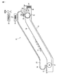
図1は、一実施形態に係る乗客コンベアの保守点検システムの概略構成例を示す。なお、本実施形態では、乗客コンベアがエスカレータである場合を想定して説明するが、これに限定されず、乗客コンベアはオートロード(動く歩道)などであっても良い。図中の10は、エスカレータ全体を示す。
Hereinafter, embodiments will be described with reference to the drawings.
FIG. 1 shows a schematic configuration example of a passenger conveyor maintenance and inspection system according to an embodiment. In addition, although this embodiment demonstrates and assumes the case where a passenger conveyor is an escalator, it is not limited to this, A passenger conveyor may be an auto road (moving sidewalk) etc. 10 in the figure indicates the entire escalator.
エスカレータ10は、例えば、建物の上階と下階との間に傾斜して設置される。このエスカレータ10は、隙間なく連結された多数の踏段(ステップ)11を上部機械室12の乗降口と下部機械室13の乗降口との間で循環移動させることで、踏段11上に搭乗した乗客を搬送する。
For example, the
各踏段11は、無端状の連結チェーン14によって連結されており、建物の床下に設置されたトラス15内に配置されている。トラス15の内部には、上部スプロケット16と下部スプロケット17が配置されており、これらの間に連結チェーン14が巻き掛けられている。 Each step 11 is connected by an endless connection chain 14 and is arranged in a truss 15 installed under the floor of the building. Inside the truss 15, an upper sprocket 16 and a lower sprocket 17 are arranged, and a connecting chain 14 is wound around them.
上部スプロケット16と下部スプロケット17のいずれか一方(この例では上部スプロケット16)には、モータや減速機などを有する駆動装置18が連結されている。この駆動装置18により、スプロケット16,17が回転し、スプロケット16,17に噛み合う連結チェーン14を介して複数の踏段11が図示しない案内レールにガイドされながら上部機械室12の乗降口と下部機械室13の乗降口との間を循環移動する。
A
また、トラス15の上部には、各踏段11の両側面と対向するように一対の図示しないスカートガードが踏段11の移動方向に沿って設置されている。この一対のスカートガード上にそれぞれ欄干19が立設されている。この欄干19の周囲にはベルト状のハンドレール20が装着されている。ハンドレール20は、踏段11に搭乗している乗客が把持する手摺であり、例えば駆動装置18の駆動力が伝達されることで、踏段11の移動と同期して周回する。
A pair of skirt guards (not shown) are installed on the truss 15 along the moving direction of the steps 11 so as to face both side surfaces of each step 11. A
上部機械室12及び下部機械室13の乗降口には、乗降板がそれぞれ設置される。乗降板は、乗客がエスカレータ10の乗降時にその上を通行するものである。乗客がエスカレータ10の乗降時に通行する通路は、複数の乗降板によって構成され、各乗降板は個別に取り外し可能に設置される。上部機械室12及び下部機械室13は、この乗降板の下方にそれぞれ設けられている。すなわち、乗降板は、上部機械室12及び下部機械室13の天井にも相当する。
A boarding / alighting board is respectively installed in the entrance / exit of the upper machine room 12 and the
上部機械室12には、駆動装置18の他に、エスカレータ10の運行制御を行う制御盤21が設置されている。この制御盤21は、エスカレータ10の運行制御を行うと共に、当該エスカレータ10の稼働履歴を示す稼働データや、当該エスカレータ10に生じた異常や故障を示すエラーデータなどの保守データを図示されない内部メモリに格納している。この保守データは、保守点検作業時に保守員によって収集され、エスカレータ10の保守点検(例えば、エスカレータ10を構成する部品の交換時期の推定など)に利用される。
In the upper machine room 12, in addition to the
上部機械室12外であって、上部機械室12の乗降口近傍には端末接続部22が設けられる。端末接続部22は、第1信号線(ケーブル)23を介して制御盤21に有線接続される。第1信号線23は、制御盤21に格納される保守データの受け渡しに利用される。端末接続部22は、保守点検作業時に使用される外部端末24を接続するための接続ポート22aを備えている。この接続ポート22aには、例えば、保守員が所持する保守点検用の端末(以下、保守員端末と表記する)25と近距離無線通信を行う機能を有した外部端末24が接続される。
A
なお、接続ポート22aのバス規格(換言すると、外部端末24を接続ポート22aに接続する方式)としては、例えば、USB(Universal Serial Bus)規格などが一例として挙げられる。但し、上記したバス規格はあくまで一例であり、これに限られるものでない。例えば、外部端末24は光ケーブルを介して接続ポート22aに接続されても良い。また、図1中では、接続ポート22aが端末接続部22に1つだけ設けられている場合を例示しているが、これに限られず、接続ポート22aは端末接続部22に任意の数だけ設けられていても良い。
An example of the bus standard for the
保守員端末25は、例えば、接続ポート22aに接続される外部端末24と近距離無線通信を行い、制御盤21内の内部メモリに格納された保守データを収集する。具体的には、保守員端末25は、次のようにして保守データを収集する。
The
まず、保守員端末25は、接続ポート22aに接続された外部端末24とペアリングを行う。これによれば、保守員端末25と外部端末24との間において近距離無線通信を行う環境が整えられる。次に、保守員端末25は、保守員の操作に応じて、保守データの収集を要求する旨の指示信号を近距離無線通信により外部端末24に送出する。該指示信号は、外部端末24及び第1信号線23を介して制御盤21に入力される。制御盤21は、この指示信号の入力に応じて、内部メモリに格納された保守データを読み出し、該保守データを外部端末24に送出する。この保守データは、第1信号線23及び外部端末24を介して、近距離無線通信により保守員端末25に入力される。以上のようにして、保守員端末25は保守データを収集する。
First, the
なお、外部端末24と保守員端末25との間で行う近距離無線通信の規格としては、例えば、Wi−Fi(登録商標)やBluetooth(登録商標)などが一例として挙げられる。但し、本実施形態に係る乗客コンベアの保守点検システムにおいては、近距離無線通信の規格として、Wi−FiよりもBluetoothが利用される方が好ましい。これは、Bluetoothの方がWi−Fiよりも通信距離が短いためである。
Note that examples of short-range wireless communication standards performed between the external terminal 24 and the
一般的に、Bluetoothの通信距離はおよそ10メートルとされている。一方、Wi−Fiの通信距離はおよそ100メートルとされている。近距離無線通信の規格としてWi−Fiが利用される場合、通信距離が長いので、他の階に設置される別のエスカレータに接続される外部端末や、エスカレータ近傍に設けられる他の電子機器と電波干渉を起こす可能性が高くなる。つまり、外部端末24と保守員端末25との間で安定した無線通信を行うことができない恐れが生じてしまう。一方、近距離無線通信の規格としてBluetoothが利用される場合、通信距離が短いので、他の電子機器と電波干渉を起こす可能性は低く、外部端末24と保守員端末25との間で安定した無線通信を行うことができる。
Generally, the communication distance of Bluetooth is about 10 meters. On the other hand, the communication distance of Wi-Fi is about 100 meters. When Wi-Fi is used as a short-range wireless communication standard, since the communication distance is long, an external terminal connected to another escalator installed on another floor and other electronic devices provided near the escalator The possibility of causing radio wave interference increases. That is, there is a possibility that stable wireless communication cannot be performed between the external terminal 24 and the
なお、上記した近距離無線通信の規格はあくまで一例であり、これに限られるものでない。 The short-range wireless communication standard described above is merely an example, and the present invention is not limited to this.
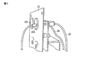
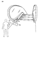
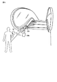
次に、図2乃至図4を参照して、端末接続部22について詳細に説明する。
端末接続部22は、例えば図2乃至図4に示すように、エスカレータ10の乗降口近傍に設けられる操作盤であっても良い。なお、ここでは、端末接続部22が操作盤である場合を例示しているが、これに限られず、端末接続部22は操作盤とは別に設けられても良い。例えば、端末接続部22は、図5に示すように、上部機械室12の乗降口近傍であって、欄干19の内デッキの任意の場所に、操作盤とは別に設けられても良い。或いは、端末接続部22は、図6に示すように、上部機械室12の乗降口近傍であって、欄干19の外デッキの任意の場所に、操作盤とは別に設けられても良い。図6に示すように、端末接続部22が欄干19の外デッキの任意の場所に設けられることで、保守員は、乗客の通行を妨げることなく保守データの収集を行うことができる。以下では、端末接続部22を、操作盤22とも表記して説明する。
Next, the
For example, as shown in FIGS. 2 to 4, the
操作盤22には、図2乃至図4に示すように、接続ポート22aの他に、非常停止ボタン22bが設けられている。操作盤22は、図3に示すように、第1信号線23とは別に、第2信号線26を介しても制御盤21に有線接続されている。第2信号線26は、エスカレータ10の運行制御に関する制御信号の受け渡しに利用される。具体的には、第2信号線26は、非常停止ボタン22bが乗客などによって押下された際に、該非常停止ボタン22bが押下されたことを示す信号や、該信号に応じて制御盤21から送出されるエスカレータ10を緊急停止させるための制御信号などの受け渡しに利用される。
As shown in FIGS. 2 to 4, the
なお、本実施形態においては、保守データの受け渡しに利用される第1信号線23と、制御信号の受け渡しに利用される第2信号線26とが別々に制御盤21に有線接続されている構成を例示したが、第1信号線23と第2信号線26の両方の機能を兼ね備えた1本の信号線が制御盤21に有線接続される構成であっても良い。
In the present embodiment, the
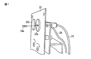
図2乃至図4においては、外部端末24として、保守員端末25と近距離無線通信を行う機能を有した通信アダプタ24aが接続ポート22aに接続された場合を例示している。この通信アダプタ24aは、電池またはAC電源からの電力によって駆動する。なお、通信アダプタ24aの形態は、図2乃至図4に示した形態に限られず、例えば図7に示すように、小型化された形態であっても良い。通信アダプタ24aは、図2乃至図4に示す形態の場合、乗客への安全面を考慮して、保守点検作業時のみ接続される方が好ましい。一方で、通信アダプタ24aは、図7に示す形態の場合、保守点検作業時のみ接続されても良いし、常時接続されたままでも良い。保守点検作業時のみ接続される場合、通信アダプタ24aが接続されていない時は、接続ポート22aを埃などの異物から保護するための保護キャップ(カバー)が取り付けられる。一方、常時接続されたままの場合、通信アダプタ24a自身を悪戯などから保護するための保護キャップ(カバー)が取り付けられる。
2 to 4 exemplify a case where a
図2乃至図4においては、通信アダプタ24aが端末接続部22の接続ポート22aに取り外し可能に接続される(外付けされる)場合を例示したが、これに限られず、例えば図8に示すように、通信アダプタ24aは、容易に取り外しできないように、エスカレータ10に内蔵されていても良い。これによれば、保守員は保守点検作業の度に接続ポート22aに通信アダプタ24aを接続する必要がなくなるので、保守員の作業効率を向上させることができるという利点を得ることができる。また、外的要因(例えば、悪戯など)によって、通信アダプタ24aが故障する可能性を低くすることができる。
2 to 4 exemplify the case where the
以上説明した一実施形態によれば、乗客コンベアの保守点検システムは、上部機械室12外であって、上部機械室12の乗降口近傍に保守員端末25と近距離無線通信を行う機能を有した外部端末24を接続可能な接続ポート22aを備えている。このため、保守員は、保守点検作業の度に、乗降板を取り外して上部機械室12内に降り、制御盤21に保守員端末25を接続しなくても、保守データを収集することができる。
According to the embodiment described above, the passenger conveyor maintenance and inspection system has a function of performing near field communication with the
また、上述したように、保守データを収集するために乗降板を取り外す必要がないので、エスカレータ10の運転を停止させることなく、保守データを収集することができる。すなわち、乗客へのサービスを低下させることなく、保守データを収集することができる。
Further, as described above, since it is not necessary to remove the boarding / alighting plate in order to collect the maintenance data, the maintenance data can be collected without stopping the operation of the
さらに、上述したように、保守データを収集するために乗降板を取り外す必要がないので、保守データを収集するにあたって必要とされる保守員の数を減らすことができる。一般的に、乗降板は1枚あたり10数キログラムの重さを有しており、従来であれば、保守データを収集するにあたって乗降板を取り外すために、少なくとも2人の保守員が必要であった。しかしながら、本実施形態によれば、保守データを収集するにあたって乗降板を取り外す必要がないので、保守データを収集するために必要な保守員の数を減らすことができる。 Furthermore, as described above, since it is not necessary to remove the boarding board in order to collect maintenance data, the number of maintenance personnel required to collect maintenance data can be reduced. In general, each board has a weight of more than 10 kilograms, and conventionally, at least two maintenance personnel are required to remove the board to collect the maintenance data. It was. However, according to the present embodiment, since it is not necessary to remove the boarding / alighting board when collecting maintenance data, the number of maintenance personnel necessary for collecting maintenance data can be reduced.
さらに、接続ポート22aが、一般的に電波感度が悪いとされる上部機械室12の外に設けられているので、外部端末24と保守員端末25との間で安定した無線通信を行うことができる。
Furthermore, since the
なお、本実施形態においては、接続ポート22aには、保守員端末25と近距離無線通信を行う機能を有した外部端末24が接続されるとしたが、図9に示すように、接続ポート22aには保守員端末25が有線接続されても良い。この場合であっても、上部機械室12の天井に相当する乗降板を取り外す必要がないので、上述と同様な効果を得ることができる。
In the present embodiment, the
なお、本発明のいくつかの実施形態を説明したが、これらの実施形態は、例として提示したものであり、発明の範囲を限定することは意図していない。これら新規な実施形態は、その他の様々な形態で実施されることが可能であり、発明の要旨を逸脱しない範囲で、種々の省略、置き換え、変更を行うことができる。これら実施形態やその変形は、発明の範囲や要旨に含まれるとともに、特許請求の範囲に記載された発明とその均等の範囲に含まれる。 In addition, although some embodiment of this invention was described, these embodiment is shown as an example and is not intending limiting the range of invention. These novel embodiments can be implemented in various other forms, and various omissions, replacements, and changes can be made without departing from the scope of the invention. These embodiments and modifications thereof are included in the scope and gist of the invention, and are included in the invention described in the claims and the equivalents thereof.
10…エスカレータ、11…踏段、12…上部機械室、13…下部機械室、14…連結チェーン、15…トラス、16…上部スプロケット、17…下部スプロケット、18…駆動装置、19…欄干、20…ハンドレール、21…制御盤、22…端末接続部、22a…接続ポート、22b…非常停止ボタン、23…第1信号線、24…外部端末、24a…通信アダプタ、25…保守員端末、26…第2信号線。
DESCRIPTION OF
Claims (9)
前記機械室外に設けられ、前記制御盤と有線接続される端末接続部と
を具備し、
前記端末接続部は、
前記乗客コンベアの保守点検作業時に使用される外部端末を接続するための接続ポートを有することを特徴とする乗客コンベアの保守点検システム。 A control panel installed in the machine room provided below the passenger conveyor boarding board;
A terminal connection unit provided outside the machine room and connected to the control panel by wire;
The terminal connection unit is
A passenger conveyor maintenance / inspection system comprising a connection port for connecting an external terminal used during maintenance / inspection work of the passenger conveyor.
保守員が所持する保守点検用の端末と近距離無線通信を行う機能を備えていることを特徴とする請求項1に記載の乗客コンベアの保守点検システム。 The external terminal is
The passenger conveyor maintenance and inspection system according to claim 1, further comprising a function of performing short-range wireless communication with a maintenance and inspection terminal owned by a maintenance staff.
前記外部端末との近距離無線通信によって前記制御盤に格納される保守データを収集することを特徴とする請求項2に記載の乗客コンベアの保守点検システム。 The terminal for maintenance inspection is
The maintenance inspection system for a passenger conveyor according to claim 2, wherein maintenance data stored in the control panel is collected by short-range wireless communication with the external terminal.
保守員が所持する保守点検用の端末であることを特徴とする請求項1に記載の乗客コンベアの保守点検システム。 The external terminal is
2. The passenger conveyor maintenance inspection system according to claim 1, which is a maintenance inspection terminal possessed by a maintenance staff.
前記端末接続部に有線接続されることによって前記制御盤に格納される保守データを収集することを特徴とする請求項4に記載の乗客コンベアの保守点検システム。 The terminal for maintenance inspection is
The maintenance inspection system for a passenger conveyor according to claim 4, wherein maintenance data stored in the control panel is collected by wire connection to the terminal connection unit.
前記乗客コンベアに設置される一対の欄干の内デッキに設けられることを特徴とする請求項1に記載の乗客コンベアの保守点検システム。 The terminal connection unit is
2. The passenger conveyor maintenance inspection system according to claim 1, wherein the passenger conveyor maintenance inspection system is provided on an inner deck of a pair of balustrades installed on the passenger conveyor.
前記内デッキに設置される非常停止ボタンを含む操作盤に設けられることを特徴とする請求項6に記載の乗客コンベアの保守点検システム。 The terminal connection unit is
The passenger conveyor maintenance and inspection system according to claim 6, wherein the passenger conveyor maintenance inspection system is provided on an operation panel including an emergency stop button installed on the inner deck.
前記乗客コンベアに設置される一対の欄干の外デッキに設けられることを特徴とする請求項1に記載の乗客コンベアの保守点検システム。 The terminal connection unit is
2. The passenger conveyor maintenance inspection system according to claim 1, wherein the passenger conveyor maintenance inspection system is provided on an outer deck of a pair of balustrades installed on the passenger conveyor.
前記機械室外に設けられ、前記制御盤と有線接続される通信端末と
を具備し、
前記通信端末は、
前記乗客コンベアの保守点検作業に保守員が所持する保守点検用の端末に対して、前記制御盤に格納される保守データを近距離無線通信によって送信することを特徴とする乗客コンベアの保守点検システム。 A control panel installed in the machine room provided below the passenger conveyor boarding board;
A communication terminal provided outside the machine room and connected to the control panel by wire;
The communication terminal is
Maintenance and inspection system for passenger conveyor, wherein maintenance data stored in the control panel is transmitted by short-range wireless communication to a maintenance and inspection terminal possessed by maintenance personnel for maintenance and inspection work of the passenger conveyor .
Priority Applications (2)
| Application Number | Priority Date | Filing Date | Title |
|---|---|---|---|
| JP2016030798A JP2017149497A (en) | 2016-02-22 | 2016-02-22 | Passenger conveyor maintenance/inspection system |
| CN201610298052.0A CN107098254A (en) | 2016-02-22 | 2016-05-06 | The maintenance inspection system of passenger conveyors |
Applications Claiming Priority (1)
| Application Number | Priority Date | Filing Date | Title |
|---|---|---|---|
| JP2016030798A JP2017149497A (en) | 2016-02-22 | 2016-02-22 | Passenger conveyor maintenance/inspection system |
Publications (1)
| Publication Number | Publication Date |
|---|---|
| JP2017149497A true JP2017149497A (en) | 2017-08-31 |
Family
ID=59658493
Family Applications (1)
| Application Number | Title | Priority Date | Filing Date |
|---|---|---|---|
| JP2016030798A Pending JP2017149497A (en) | 2016-02-22 | 2016-02-22 | Passenger conveyor maintenance/inspection system |
Country Status (2)
| Country | Link |
|---|---|
| JP (1) | JP2017149497A (en) |
| CN (1) | CN107098254A (en) |
Families Citing this family (2)
| Publication number | Priority date | Publication date | Assignee | Title |
|---|---|---|---|---|
| WO2021250747A1 (en) * | 2020-06-08 | 2021-12-16 | 三菱電機ビルテクノサービス株式会社 | Passenger conveyor renewal tool and passenger conveyor renewal method |
| DE202022100139U1 (en) | 2022-01-12 | 2023-04-14 | Norman Nieland | Device for controlling escalators or moving walks |
Citations (4)
| Publication number | Priority date | Publication date | Assignee | Title |
|---|---|---|---|---|
| JP2004224560A (en) * | 2003-01-27 | 2004-08-12 | Hitachi Building Systems Co Ltd | Monitoring device of passenger conveyor |
| JP2004224558A (en) * | 2003-01-27 | 2004-08-12 | Hitachi Building Systems Co Ltd | Monitoring device of passenger conveyor |
| JP2006151670A (en) * | 2004-12-01 | 2006-06-15 | Mitsubishi Electric Building Techno Service Co Ltd | Man conveyor remote monitoring system |
| JP2007169023A (en) * | 2005-12-26 | 2007-07-05 | Mitsubishi Electric Corp | Portable display device of passenger conveyor |
Family Cites Families (3)
| Publication number | Priority date | Publication date | Assignee | Title |
|---|---|---|---|---|
| TWI243793B (en) * | 2000-08-30 | 2005-11-21 | Hitachi Ltd | Communication device for passenger conveying device |
| CN201272651Y (en) * | 2008-03-13 | 2009-07-15 | 上海爱登堡电梯有限公司 | Terminal with human-computer conversation display interface used for escalator |
| JP4937373B2 (en) * | 2010-03-30 | 2012-05-23 | 株式会社東芝 | Data collection system |
-
2016
- 2016-02-22 JP JP2016030798A patent/JP2017149497A/en active Pending
- 2016-05-06 CN CN201610298052.0A patent/CN107098254A/en active Pending
Patent Citations (4)
| Publication number | Priority date | Publication date | Assignee | Title |
|---|---|---|---|---|
| JP2004224560A (en) * | 2003-01-27 | 2004-08-12 | Hitachi Building Systems Co Ltd | Monitoring device of passenger conveyor |
| JP2004224558A (en) * | 2003-01-27 | 2004-08-12 | Hitachi Building Systems Co Ltd | Monitoring device of passenger conveyor |
| JP2006151670A (en) * | 2004-12-01 | 2006-06-15 | Mitsubishi Electric Building Techno Service Co Ltd | Man conveyor remote monitoring system |
| JP2007169023A (en) * | 2005-12-26 | 2007-07-05 | Mitsubishi Electric Corp | Portable display device of passenger conveyor |
Also Published As
| Publication number | Publication date |
|---|---|
| CN107098254A (en) | 2017-08-29 |
Similar Documents
| Publication | Publication Date | Title |
|---|---|---|
| JP5081751B2 (en) | Elevator maintenance safety device | |
| CN103764532A (en) | Electronically controlled elevator | |
| JP6522203B1 (en) | Passenger conveyor anomaly detection system | |
| US10519007B2 (en) | Passenger conveyor | |
| JP5795088B2 (en) | Passenger conveyor | |
| JP7234335B1 (en) | PASSENGER CONVEYOR SYSTEM, PASSENGER CONVEYOR AND MOVEMENT USED THEREOF | |
| CN114040883B (en) | Point inspection indicating device of mobile auxiliary device | |
| JP5945023B1 (en) | Passenger conveyor | |
| JP6453424B1 (en) | Passenger conveyor | |
| JP2017149497A (en) | Passenger conveyor maintenance/inspection system | |
| JP2013249166A (en) | Passenger detecting device of passenger conveyor | |
| JP2012144328A (en) | Elevator | |
| US20170240380A1 (en) | Evacuation concept for elevator systems | |
| CN110921480A (en) | Escalator accident detection system | |
| JP2017007799A (en) | Passenger conveyor program update system | |
| JP6591615B1 (en) | Abnormality diagnosis system for passenger conveyor | |
| CN106276553A (en) | Automatic speed regulation staircase and method of work thereof | |
| CN112875484B (en) | Chain slack detection device for passenger conveyor | |
| JP5920680B1 (en) | Passenger conveyor | |
| JP6013558B1 (en) | Passenger conveyor | |
| JP2013129524A (en) | Safety device for passenger conveyor | |
| JP7309970B1 (en) | Passenger conveyor system and passenger conveyor | |
| JP2019199353A (en) | Passenger conveyor | |
| JP6641035B1 (en) | Passenger conveyor | |
| CN210150556U (en) | Passenger conveyor |
Legal Events
| Date | Code | Title | Description |
|---|---|---|---|
| A02 | Decision of refusal |
Free format text: JAPANESE INTERMEDIATE CODE: A02 Effective date: 20170606 |