JP2017149332A - Vehicular wire harness structure - Google Patents
Vehicular wire harness structure Download PDFInfo
- Publication number
- JP2017149332A JP2017149332A JP2016034820A JP2016034820A JP2017149332A JP 2017149332 A JP2017149332 A JP 2017149332A JP 2016034820 A JP2016034820 A JP 2016034820A JP 2016034820 A JP2016034820 A JP 2016034820A JP 2017149332 A JP2017149332 A JP 2017149332A
- Authority
- JP
- Japan
- Prior art keywords
- function
- wire harness
- vehicle
- module
- connector
- Prior art date
- Legal status (The legal status is an assumption and is not a legal conclusion. Google has not performed a legal analysis and makes no representation as to the accuracy of the status listed.)
- Granted
Links
Images


Classifications
-
- B—PERFORMING OPERATIONS; TRANSPORTING
- B60—VEHICLES IN GENERAL
- B60R—VEHICLES, VEHICLE FITTINGS, OR VEHICLE PARTS, NOT OTHERWISE PROVIDED FOR
- B60R16/00—Electric or fluid circuits specially adapted for vehicles and not otherwise provided for; Arrangement of elements of electric or fluid circuits specially adapted for vehicles and not otherwise provided for
- B60R16/02—Electric or fluid circuits specially adapted for vehicles and not otherwise provided for; Arrangement of elements of electric or fluid circuits specially adapted for vehicles and not otherwise provided for electric constitutive elements
- B60R16/03—Electric or fluid circuits specially adapted for vehicles and not otherwise provided for; Arrangement of elements of electric or fluid circuits specially adapted for vehicles and not otherwise provided for electric constitutive elements for supply of electrical power to vehicle subsystems or for
-
- B—PERFORMING OPERATIONS; TRANSPORTING
- B60—VEHICLES IN GENERAL
- B60R—VEHICLES, VEHICLE FITTINGS, OR VEHICLE PARTS, NOT OTHERWISE PROVIDED FOR
- B60R16/00—Electric or fluid circuits specially adapted for vehicles and not otherwise provided for; Arrangement of elements of electric or fluid circuits specially adapted for vehicles and not otherwise provided for
- B60R16/02—Electric or fluid circuits specially adapted for vehicles and not otherwise provided for; Arrangement of elements of electric or fluid circuits specially adapted for vehicles and not otherwise provided for electric constitutive elements
- B60R16/0207—Wire harnesses
- B60R16/0215—Protecting, fastening and routing means therefor
-
- H—ELECTRICITY
- H01—ELECTRIC ELEMENTS
- H01B—CABLES; CONDUCTORS; INSULATORS; SELECTION OF MATERIALS FOR THEIR CONDUCTIVE, INSULATING OR DIELECTRIC PROPERTIES
- H01B7/00—Insulated conductors or cables characterised by their form
Abstract
Description
本発明は車両用ワイヤハーネス構造に関する。 The present invention relates to a vehicle wiring harness structure.
自動車などの車両には、車両の走行と直接関係のある機器の他に様々な補助的な機器(補機:アクセサリ)が搭載されている。例えば、エアコン、ワイパー、パワーウインドゥ、電動シート、各種灯具、ドアロック装置、シートヒータ、霜取り用熱線のような電装品が補機として車両に搭載される。 In vehicles such as automobiles, various auxiliary devices (auxiliary equipment: accessories) are mounted in addition to devices directly related to the traveling of the vehicle. For example, electrical components such as air conditioners, wipers, power windows, electric seats, various lamps, door lock devices, seat heaters, and defrosting heat wires are mounted on the vehicle as auxiliary equipment.
補機に属する様々な電装品については、全ての車両に搭載される標準的な電装品もあるし、車両の種類、グレード、仕向地、ユーザの選択などに応じて選択的に搭載の有無が決定されるオプション電装品もある。また、当該車両の設計当初には想定していなかった新たな機能を実現する電装品が追加的に搭載される場合もある。 There are standard electrical components that are mounted on all vehicles for various electrical components belonging to the auxiliary machinery, and whether or not they are selectively mounted according to the vehicle type, grade, destination, user's choice, etc. Some optional electrical components are determined. In addition, an electrical component that realizes a new function that was not assumed at the initial design of the vehicle may be additionally installed.
このような車両に搭載される様々な電装品は、それぞれを適切に制御する必要があるので、一般的には電子制御ユニット(ECU)と各電装品とが車両に搭載したワイヤハーネスを介して接続される。 Since various electrical components mounted on such a vehicle need to be appropriately controlled, generally, an electronic control unit (ECU) and each electrical component are connected via a wire harness mounted on the vehicle. Connected.
例えば、特許文献1に示された電子機器制御システムにおいては、1つの電子制御ユニットの内部に、標準の電子機器を制御するための制御手段と、オプションの電子機器を制御するための制御手段とを設けてある。また、前記電子制御ユニットと標準の電子機器との間をワイヤハーネスに含まれる標準回路で接続し、前記電子制御ユニットとオプションの電子機器との間を前記ワイヤハーネスに含まれるオプション回路で接続している。また、前記オプション回路には、通信コネクタが設けてある。
For example, in the electronic device control system disclosed in
また、特許文献2に示されたワイヤハーネス構造体においては、一端を電子制御ユニットと接続した1つのワイヤハーネスの他端にジョイントコネクタを接続し、このジョイントコネクタに標準回路のワイヤハーネスとオプション回路のワイヤハーネスを接続している。また、ジョイントコネクタにCPUとドライバを内蔵した通信回路を設けている。
Further, in the wire harness structure disclosed in
また、特許文献3に示されたワイヤハーネスにおいては、電子機器毎に独立したECU(電子制御ユニット)を設けている。また、特許文献4に示された車載システムにおいては、それぞれが複数の電子機器を制御する複数のECU(電子制御ユニット)を異なるコネクタにそれぞれ接続している。
Further, in the wire harness disclosed in
前述のように、実際の車両においては補機に属するものとして、標準の電装品とオプションの電装品とが存在し、オプションの電装品は実装される場合と実装されない場合とがある。したがって、これらを制御する電子制御ユニットについては、通常は標準の電装品を制御する機能だけを搭載しているが、処理能力に十分な余力を持たせてある。そして、オプションの電装品を実装する場合には、これを制御する機能も例えば特許文献1のように標準の機能と同じ電子制御ユニットに実装する。
As described above, in an actual vehicle, there are standard electrical components and optional electrical components as belonging to an auxiliary machine, and optional electrical components may or may not be mounted. Therefore, the electronic control unit for controlling these components is usually equipped with only a function for controlling standard electrical components, but has sufficient capacity for processing capability. And when mounting an optional electrical component, the function which controls this is also mounted in the same electronic control unit as the standard function as in
一方、車両の設計時に想定していなかった新たな機能や新たな電装品を車載システムに追加したい場合もある。このような場合には、図8に示すように新たな機能や電装品を制御するための特別な機能を追加した標準電子制御ユニットECU−Bを新たに設計し、標準電子制御ユニットECU−Aの置き換えを行うのが一般的である。あるいは、新たな機能や電装品を制御するために、標準電子制御ユニットECU−Aとは別体の電子制御ユニットECU−Cを追加して、追加した電子制御ユニットECU−Cに新たな電装品をワイヤハーネスを経由して接続する。 On the other hand, there is a case where it is desired to add a new function or a new electrical component that was not assumed at the time of designing the vehicle to the in-vehicle system. In such a case, a standard electronic control unit ECU-B to which a new function and a special function for controlling electrical components are added as shown in FIG. 8 is newly designed, and the standard electronic control unit ECU-A is designed. Is generally replaced. Alternatively, in order to control new functions and electrical components, an electronic control unit ECU-C that is separate from the standard electronic control unit ECU-A is added, and new electrical components are added to the added electronic control unit ECU-C. Is connected via a wire harness.
しかしながら、図8のように標準電子制御ユニットECU−Aの他に、別体の電子制御ユニットECU−Cを追加する場合には、部品数の大幅な増加により高価なシステムになってしまう。また、標準電子制御ユニットECU−Bのように1つの電子制御ユニットだけで様々な機能の追加に対応可能にするためには、標準電子制御ユニットの能力に十分な余裕を持たせなければならず、高価になってしまう。つまり、オプションの電装品を接続しない場合や、機能の追加をしない場合には、必要以上の能力を標準電子制御ユニットに持たせることになるため、実際に実行する機能に比べて標準電子制御ユニットの部品コストが割高になるのは避けられない。 However, when a separate electronic control unit ECU-C is added in addition to the standard electronic control unit ECU-A as shown in FIG. 8, the system becomes expensive due to a significant increase in the number of parts. In addition, in order to be able to cope with the addition of various functions with only one electronic control unit, such as the standard electronic control unit ECU-B, it is necessary to provide sufficient capacity for the standard electronic control unit. It becomes expensive. In other words, when optional electrical components are not connected or when functions are not added, the standard electronic control unit will have more capacity than necessary, so the standard electronic control unit is more than the function actually executed. It is inevitable that the cost of parts will be expensive.
しかし、車載システムに新たな機能や新たな電装品を追加する可能性がある場合であっても、追加する機能や電装品の仕様は最初の設計時には未知であるため、標準電子制御ユニットの余力を最適化することはできない。 However, even if there is a possibility of adding new functions or new electrical components to the in-vehicle system, the specifications of the functions and electrical components to be added are unknown at the time of the initial design. Cannot be optimized.
本発明は、上述した事情に鑑みてなされたものであり、その目的は、追加する機能や追加する電装品の仕様に合わせてシステム構成を最適化するために役立つ車両用ワイヤハーネス構造を提供することにある。 The present invention has been made in view of the above-described circumstances, and an object of the present invention is to provide a vehicle wire harness structure that is useful for optimizing a system configuration in accordance with the specifications of functions to be added and electrical components to be added. There is.
前述した目的を達成するために、本発明に係る車両用ワイヤハーネス構造は、下記(1)〜(5)を特徴としている。 In order to achieve the above-described object, the vehicle wire harness structure according to the present invention is characterized by the following (1) to (5).
(1) 車両に取付けられる第1電装品と、前記第1電装品を制御する主制御機能部と、を接続する第1ワイヤハーネスと、
前記主制御機能部に一端が接続される第2ワイヤハーネスと、を備え、
前記第2ワイヤハーネスは、前記車両に取付けられる第2電装品を制御する副制御機能部を他端に有する、
ことを特徴とする車両用ワイヤハーネス構造。
(1) a first wire harness that connects a first electrical component attached to a vehicle and a main control function unit that controls the first electrical component;
A second wire harness having one end connected to the main control function unit,
The second wire harness has, at the other end, a sub-control function unit that controls a second electrical component attached to the vehicle.
A vehicle wire harness structure characterized by the above.
上記(1)の構成の車両用ワイヤハーネス構造によれば、前記第2電装品を追加する場合に、前記第2電装品の処理を前記主制御機能部が受け持つ必要がなくなるため、前記主制御機能部に必要以上の能力を持たせる必要がない。また、前記第2電装品の仕様に合わせて前記副制御機能部の処理能力を調整できるので、前記副制御機能部の部品コストの上昇を抑制可能である。 According to the vehicle wiring harness structure having the configuration (1), when the second electrical component is added, it is not necessary for the main control function unit to handle the processing of the second electrical component. It is not necessary to give the functional part more than necessary. Moreover, since the processing capability of the sub-control function unit can be adjusted according to the specifications of the second electrical component, it is possible to suppress an increase in the component cost of the sub-control function unit.
(2) 前記第2ワイヤハーネスの副制御機能部は、複数種類ある前記第2電装品のいずれか1つを制御する単機能を有する、
ことを特徴とする上記(1)に記載の車両用ワイヤハーネス構造。
(2) The sub-control function unit of the second wire harness has a single function of controlling any one of the plurality of second electrical components.
The wire harness structure for a vehicle according to the above (1), characterized in that:
上記(2)の構成の車両用ワイヤハーネス構造によれば、実際に接続する前記第2電装品の種類に適合する特定の単機能のみを前記副制御機能部に持たせることが可能であり、前記副制御機能部の部品コストを抑制するように、その構成を最適化できる。 According to the vehicle wire harness structure of the configuration (2), it is possible to give the sub-control function unit only a specific single function that matches the type of the second electrical component to be actually connected, The configuration can be optimized so as to reduce the component cost of the sub-control function unit.
(3) 前記副制御機能部は、複数種類ある前記第2電装品のうち少なくとも2つを制御する複数機能を有し、該副制御機能部に接続された前記第2電装品を制御する、
ことを特徴とする上記(1)に記載の車両用ワイヤハーネス構造。
(3) The sub-control function unit has a plurality of functions for controlling at least two of the plurality of types of the second electrical component, and controls the second electrical component connected to the sub-control function unit.
The wire harness structure for a vehicle according to the above (1), characterized in that:
上記(3)の構成の車両用ワイヤハーネス構造によれば、前記副制御機能部を1つ設けるだけで複数種類の前記第2電装品を制御できるので、ワイヤハーネス全体の構成やシステムの構成が複雑になるのを避けることが可能である。 According to the vehicular wire harness structure having the configuration of (3) above, a plurality of types of the second electrical components can be controlled by providing only one sub-control function unit. It is possible to avoid complications.
(4) 前記第2ワイヤハーネスを複数備え、
複数の前記第2ワイヤハーネスが前記第1ワイヤハーネスにそれぞれ接続される、
ことを特徴とする上記(1)乃至(3)のいずれかに記載の車両用ワイヤハーネス構造。
(4) A plurality of the second wire harnesses are provided,
A plurality of the second wire harnesses are respectively connected to the first wire harnesses.
The vehicle wiring harness structure according to any one of the above (1) to (3).
上記(4)の構成の車両用ワイヤハーネス構造によれば、新たな電装品や機能を追加する場合であっても、ワイヤハーネス全体を作り直したり取り替える必要がなく、前記第1ワイヤハーネスが既に車両上に配索されている状態で、追加する前記第2ワイヤハーネスを前記第1ワイヤハーネスに対して後付けすることができる。したがって、システム構成の変更に伴う作業の負担や作業コストを大幅に軽減できる。 According to the vehicle wire harness structure having the configuration (4), even when a new electrical component or function is added, there is no need to recreate or replace the entire wire harness, and the first wire harness is already in the vehicle. The second wire harness to be added can be retrofitted to the first wire harness while being routed above. Therefore, it is possible to greatly reduce the work burden and work cost associated with the change in the system configuration.
(5) 前記第2ワイヤハーネスに一端が接続される第3ワイヤハーネスを備え、
前記第3ワイヤハーネスは、前記車両に取付けられる第3電装品を制御する副制御機能部を他端に有する、
ことを特徴とする上記(1)乃至(4)のいずれかに記載の車両用ワイヤハーネス構造。
(5) comprising a third wire harness having one end connected to the second wire harness;
The third wire harness has a sub-control function unit for controlling a third electrical component attached to the vehicle at the other end,
The vehicle wiring harness structure according to any one of the above (1) to (4).
上記(5)の構成の車両用ワイヤハーネス構造によれば、前記第3電装品を追加する場合に、前記第3電装品の処理を前記主制御機能部が受け持つ必要がなくなるため、前記主制御機能部に必要以上の能力を持たせる必要がない。また、前記第3電装品の仕様に合わせて前記副制御機能部の処理能力を調整できるので、前記副制御機能部の部品コストの上昇を抑制可能である。また、前記第3電装品を追加する場合であっても、ワイヤハーネス全体を作り直したり取り替える必要がなく、前記第2ワイヤハーネスが既に車両上に配索されている状態で、追加する前記第3ワイヤハーネスを前記第2ワイヤハーネスに対して後付けすることができる。したがって、システム構成の変更に伴う作業の負担や作業コストを大幅に軽減できる。 According to the vehicular wire harness structure having the configuration (5), when the third electrical component is added, the main control function unit does not have to take charge of the processing of the third electrical component. It is not necessary to give the functional part more than necessary. Moreover, since the processing capability of the sub-control function unit can be adjusted according to the specifications of the third electrical component, it is possible to suppress an increase in the component cost of the sub-control function unit. Further, even when the third electrical component is added, there is no need to recreate or replace the entire wire harness, and the third electrical component is added while the second wire harness is already routed on the vehicle. A wire harness can be retrofitted to the second wire harness. Therefore, it is possible to greatly reduce the work burden and work cost associated with the change in the system configuration.
本発明の車両用ワイヤハーネス構造によれば、追加する機能や追加する電装品の仕様に合わせてシステム構成を最適化するために役立つ。すなわち、前記第2電装品を追加する場合に、前記第2電装品の処理を前記主制御機能部が受け持つ必要がなくなるため、前記主制御機能部に必要以上の能力を持たせる必要がない。また、前記第2電装品の仕様に合わせて前記副制御機能部の処理能力を調整できるので、前記副制御機能部の部品コストの上昇を抑制可能である。 The vehicular wire harness structure of the present invention is useful for optimizing the system configuration in accordance with the function to be added and the specifications of the electrical component to be added. That is, when the second electrical component is added, it is not necessary for the main control function unit to handle the processing of the second electrical component, and therefore it is not necessary to give the main control function unit an unnecessarily high capability. Moreover, since the processing capability of the sub-control function unit can be adjusted according to the specifications of the second electrical component, it is possible to suppress an increase in the component cost of the sub-control function unit.
以上、本発明について簡潔に説明した。更に、以下に説明される発明を実施するための形態(以下、「実施形態」という。)を添付の図面を参照して通読することにより、本発明の詳細は更に明確化されるであろう。 The present invention has been briefly described above. Further, the details of the present invention will be further clarified by reading through a mode for carrying out the invention described below (hereinafter referred to as “embodiment”) with reference to the accompanying drawings. .
本発明に関する具体的な実施形態について、各図を参照しながら以下に説明する。 Specific embodiments relating to the present invention will be described below with reference to the drawings.
(第1実施形態)
<車載システムの構成例>
本発明の実施形態の車両用ワイヤハーネス構造を含む車載システムの構成例(1)を図1に示す。
(First embodiment)
<In-vehicle system configuration example>
A configuration example (1) of an in-vehicle system including a vehicle wire harness structure according to an embodiment of the present invention is shown in FIG.
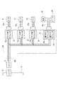
図1に示した車載システムは、制御対象として標準車載電子機器10、オプション車載電子機器30、および追加機能車載電子機器40を含んでいる。標準車載電子機器10は、車種やグレードの区別などと関係なく全ての車両に標準的に搭載される電子機器である。図1の例では、標準車載電子機器10はスイッチ11、センサ12、負荷13、およびリレー14を内蔵している。現実の車両においては、1台の車両上に多数の標準車載電子機器10が搭載される。
The in-vehicle system shown in FIG. 1 includes a standard in-vehicle
オプション車載電子機器30は、車種の違い、グレードの違い、仕向地の違い、ユーザの選択などに応じて選択的に車両に搭載される電子機器である。図1の例では、オプション車載電子機器30はスイッチ31、センサ32、および負荷33を内蔵している。現実の車両においては、1台の車両上に複数のオプション車載電子機器30が搭載される場合もあるし、オプション車載電子機器30が搭載されない場合もある。
The optional in-vehicle
追加機能車載電子機器40は、例えば車両メーカにおける改良や仕様変更などに伴って、必要に応じて各車両に追加的に搭載される電子機器である。図1の例では、追加機能車載電子機器40はスイッチ41、センサ42、および負荷43を内蔵している。現実の車両においては、1台の車両上に複数の追加機能車載電子機器40が搭載される場合もあるし、追加機能車載電子機器40が搭載されない場合もある。
The additional function on-vehicle
図1に示した主制御ユニット(ECU)20は、車種の違い等とは無関係に全ての車両に標準的に搭載される制御部であり、標準車載電子機器10のように標準的に搭載される電装品のみを制御対象として制御する標準処理機能21を備えている。また、図1に示した車載システムにはオプション車載電子機器30および追加機能車載電子機器40が含まれているが、主制御ユニット20は、オプション車載電子機器30を制御するための機能、および追加機能車載電子機器40を制御するための機能を有していない。
The main control unit (ECU) 20 shown in FIG. 1 is a control unit that is standardly mounted on all vehicles regardless of the difference in vehicle type, and is standardly mounted like the standard in-vehicle
主制御ユニット20は、2つのコネクタ22および23を備えている。また、第1ワイヤハーネスWH1が、主制御ユニット20の一方のコネクタ22と標準車載電子機器10との間を電気的に接続している。
The
第1ワイヤハーネスWH1は、基本的には複数の電線の集合体であって端部にコネクタが装着されている。図示しないが、第1ワイヤハーネスWH1は、電源を供給する電線の他に、多重データ通信が可能な通信線を備えている。なお、第1ワイヤハーネスWH1は、多重データ通信が可能な通信線の代わりに、あるいは当該通信線に加え、スイッチ11やセンサ12などから出力された信号を主制御ユニット20に直接入力する通信線(ジカ線)を備えていてもよい。また、第1ワイヤハーネスWH1は、アース(グランド)線を備えていてもよい。
The first wire harness WH1 is basically an assembly of a plurality of electric wires, and a connector is attached to an end thereof. Although not shown, the first wire harness WH1 includes a communication line capable of multiplex data communication in addition to the electric wire for supplying power. The first wire harness WH1 is a communication line that directly inputs a signal output from the
主制御ユニット20の標準処理機能21は、第1ワイヤハーネスWH1の通信線を介して標準車載電子機器10との間で通信を行いながら、組み込まれたプログラムの内容および状況に応じて標準車載電子機器10を制御する。例えば、標準処理機能21は、標準車載電子機器10におけるスイッチ11の状態やセンサ12の出力信号を読み取り、負荷13の通電のオンオフ、デューティ等を制御したり、リレー14のオンオフを制御する。
The
一方、主制御ユニット20のコネクタ23と、オプション車載電子機器30との間が、第2ワイヤハーネスWH2を介して電気的に接続されている。第2ワイヤハーネスWH2も、基本的には複数の電線の集合体であって端部にコネクタを装着してある。図1に示した第2ワイヤハーネスWH2においては、電線群55の一端にコネクタWH2aが接続され、電線群55の他端側は3つに分岐されてそれぞれの端部にコネクタWH2b、WH2c、およびWH2dが接続されている。
On the other hand, the
そして、第2ワイヤハーネスWH2のコネクタWH2aが主制御ユニット20のコネクタ23と接続されている。また、第2ワイヤハーネスWH2のコネクタWH2b、WH2c、およびWH2dは、それぞれオプション車載電子機器30のコネクタ30a、30b、および30cと接続されている。
The connector WH2a of the second wire harness WH2 is connected to the
また、コネクタWH2b、WH2c、およびWH2dの内部にはそれぞれ単機能スレーブ電子モジュールMD(1)、MD(2)、およびMD(3)が1つずつ備わっている。ここで、3つの単機能スレーブ電子モジュールMD(1)、MD(2)、およびMD(3)はそれぞれ種類が異なる。 Each of the connectors WH2b, WH2c, and WH2d includes one single-function slave electronic module MD (1), MD (2), and MD (3). Here, the three single-function slave electronic modules MD (1), MD (2), and MD (3) are different in type.
すなわち、コネクタWH2bに内蔵された単機能スレーブ電子モジュールMD(1)については、コネクタ30aに接続されたオプション車載電子機器30内のスイッチ31を制御するために必要な最小限の機能のみを実現するためにモジュール化された電子回路が選択的に用いられる。したがって、オプション車載電子機器30のスイッチ31を制御する機能を主制御ユニット20に搭載する必要はない。但し、主制御ユニット20にはマスターとして単機能スレーブ電子モジュールMD(1)との間でデータ通信するための機能が標準処理機能21として搭載されている。
That is, for the single-function slave electronic module MD (1) built in the connector WH2b, only a minimum function necessary for controlling the
また、コネクタWH2cに内蔵された単機能スレーブ電子モジュールMD(2)については、コネクタ30bに接続されたオプション車載電子機器30内のセンサ32を制御するために必要な最小限の機能のみを実現するためにモジュール化された電子回路が選択的に用いられる。したがって、オプション車載電子機器30のセンサ32を制御する機能を主制御ユニット20に搭載する必要はない。但し、主制御ユニット20にはマスターとして単機能スレーブ電子モジュールMD(2)との間でデータ通信するための機能が標準処理機能21として搭載されている。
Further, the single-function slave electronic module MD (2) built in the connector WH2c realizes only the minimum functions necessary for controlling the
また、コネクタWH2dに内蔵された単機能スレーブ電子モジュールMD(3)については、コネクタ30cに接続されたオプション車載電子機器30内の負荷33を制御するために必要な最小限の機能のみを実現するためにモジュール化された電子回路が選択的に用いられる。したがって、オプション車載電子機器30の負荷33を制御する機能を主制御ユニット20に搭載する必要はない。但し、主制御ユニット20にはマスターとして単機能スレーブ電子モジュールMD(3)との間でデータ通信するための機能が標準処理機能21として搭載されている。
Further, the single-function slave electronic module MD (3) built in the connector WH2d realizes only the minimum functions necessary for controlling the
一方、図1の車載システムは、追加機能車載電子機器40を接続するために、第3ワイヤハーネスWH3を備えている。第3ワイヤハーネスWH3も、基本的には複数の電線の集合体であって端部にコネクタを装着してある。図1に示した第3ワイヤハーネスWH3においては、電線群57の一端にコネクタWH3aが接続され、電線群57の他端側は3つに分岐されてそれぞれの端部にコネクタWH3b、WH3c、およびWH3dが接続されている。
On the other hand, the in-vehicle system of FIG. 1 includes a third wire harness WH3 in order to connect the additional function in-vehicle
そして、第3ワイヤハーネスWH3のコネクタWH3aは、第2ワイヤハーネスWH2を構成する電線群55の途中に接続されている。また、第3ワイヤハーネスWH3のコネクタWH3b、WH3c、およびWH3dは、それぞれ追加機能車載電子機器40のコネクタ40a、40b、および40cと接続されている。
And connector WH3a of 3rd wire harness WH3 is connected to the middle of
また、コネクタWH3b、WH3c、およびWH3dの内部にはそれぞれ単機能スレーブ電子モジュールMD(4)、MD(5)、およびMD(6)が1つずつ備わっている。ここで、3つの単機能スレーブ電子モジュールMD(4)、MD(5)、およびMD(6)はそれぞれ種類が異なる。 Each of the connectors WH3b, WH3c, and WH3d includes one single-function slave electronic module MD (4), MD (5), and MD (6). Here, the three single-function slave electronic modules MD (4), MD (5), and MD (6) are different in type.
すなわち、コネクタWH3bに内蔵された単機能スレーブ電子モジュールMD(4)には、コネクタ40aに接続された追加機能車載電子機器40内のスイッチ41を制御するために必要な最小限の機能のみを実現するためにモジュール化された電子回路が選択的に用いられる。したがって、追加機能車載電子機器40のスイッチ41を制御する機能を主制御ユニット20に搭載する必要はない。なお、主制御ユニット20にはマスターとして単機能スレーブ電子モジュールMD(4)との間でデータ通信するための機能が標準処理機能21として搭載されている。
In other words, the single function slave electronic module MD (4) built in the connector WH3b realizes only the minimum functions necessary for controlling the
また、コネクタWH3cに内蔵された単機能スレーブ電子モジュールMD(5)には、コネクタ40bに接続された追加機能車載電子機器40内のセンサ42を制御するために必要な最小限の機能のみを実現するためにモジュール化された電子回路が選択的に用いられる。したがって、追加機能車載電子機器40のセンサ42を制御する機能を主制御ユニット20に搭載する必要はない。また、主制御ユニット20の標準処理機能21は、マスターとして単機能スレーブ電子モジュールMD(5)との間でデータ通信するための機能を有している。
In addition, the single function slave electronic module MD (5) built in the connector WH3c realizes only the minimum functions necessary for controlling the
また、コネクタWH3dに内蔵された単機能スレーブ電子モジュールMD(6)には、コネクタ40cに接続された追加機能車載電子機器40内の負荷43を制御するために必要な最小限の機能のみを実現するためにモジュール化された電子回路が選択的に用いられる。したがって、追加機能車載電子機器40の負荷43を制御する機能を主制御ユニット20に搭載する必要はない。また、主制御ユニット20の標準処理機能21は、マスターとして単機能スレーブ電子モジュールMD(6)との間でデータ通信するための機能を有している。
In addition, the single function slave electronic module MD (6) built in the connector WH3d realizes only the minimum functions necessary for controlling the
<単機能スレーブ電子モジュールMDの仕様の具体例>
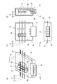
互いに種類が異なる6種類の単機能スレーブ電子モジュールMDの端子仕様を図2(A)〜図2(F)に、それぞれ示す。
<Specific example of specification of single function slave electronic module MD>
Terminal specifications of six types of single-function slave electronic modules MD of different types are shown in FIGS. 2 (A) to 2 (F), respectively.
図2(A)に示した単機能スレーブ電子モジュールMD(A)は、電気モータを制御する機能に限定してスレーブとしての機能を実現するための最小化した電子回路をモジュール化したものである。例えば、図1に示したオプション車載電子機器30内の負荷33が電気モータである場合には、コネクタWH2d内の単機能スレーブ電子モジュールMD(3)として、この単機能スレーブ電子モジュールMD(A)を選択的に採用できる。
The single-function slave electronic module MD (A) shown in FIG. 2 (A) is a module in which a minimized electronic circuit for realizing a function as a slave is limited to a function for controlling an electric motor. . For example, when the
図2(A)に示したように、単機能スレーブ電子モジュールMD(A)は、通信用の端子(最大で2つ)と、出力用の端子(最大で2つ)と、入力用の端子(最大で3つ)と、センサ用の端子(最大で3つ)と、電源用の端子(最大で2つ)と、アース(GND)用の端子(最大で2つ)とを備えることができる。つまり、単機能スレーブ電子モジュールMD(A)の最大の端子数は14である。 As shown in FIG. 2A, the single-function slave electronic module MD (A) includes a communication terminal (maximum of two), an output terminal (maximum of two), and an input terminal. (Maximum 3), sensor terminals (maximum 3), power supply terminals (maximum 2), and ground (GND) terminals (maximum 2). it can. That is, the maximum number of terminals of the single function slave electronic module MD (A) is 14.
図2(B)に示した単機能スレーブ電子モジュールMD(B)は、ヒータを制御する機能に限定してスレーブとしての機能を実現するための最小化した電子回路をモジュール化したものである。例えば、図1に示した追加機能車載電子機器40内の負荷43がヒータである場合には、コネクタWH3d内の単機能スレーブ電子モジュールMD(6)として、この単機能スレーブ電子モジュールMD(B)を選択的に採用する。
The single-function slave electronic module MD (B) shown in FIG. 2 (B) is a module obtained by modularizing a minimized electronic circuit for realizing the function as a slave only for the function of controlling the heater. For example, when the
図2(B)に示したように、単機能スレーブ電子モジュールMD(B)は、通信用の端子(最大で2つ)と、出力用の端子(最大で2つ)と、入力用の端子(最大で2つ)と、電源用の端子(最大で2つ)と、アース(GND)用の端子(最大で2つ)とを備えることができる。つまり、単機能スレーブ電子モジュールMD(B)の最大の端子数は10である。 As shown in FIG. 2B, the single-function slave electronic module MD (B) includes communication terminals (maximum of two), output terminals (maximum of two), and input terminals. (Maximum two), power supply terminals (maximum two), and ground (GND) terminals (maximum two). That is, the maximum number of terminals of the single function slave electronic module MD (B) is ten.
図2(C)に示した単機能スレーブ電子モジュールMD(C)は、ランプを制御する機能に限定してスレーブとしての機能を実現するための最小化した電子回路をモジュール化したものである。例えば、図1に示した追加機能車載電子機器40内の負荷43がランプである場合には、コネクタWH3d内の単機能スレーブ電子モジュールMD(6)として、この単機能スレーブ電子モジュールMD(C)を選択的に採用する。
The single-function slave electronic module MD (C) shown in FIG. 2C is a module obtained by modularizing a minimized electronic circuit for realizing a function as a slave only for the function of controlling the lamp. For example, when the
図2(C)に示したように、単機能スレーブ電子モジュールMD(C)は、通信用の端子(最大で2つ)と、出力用の端子(最大で2つ)と、入力用の端子(最大で2つ)と、センサ用の端子(最大で2つ)と、電源用の端子(最大で2つ)と、アース(GND)用の端子(最大で2つ)とを備えることができる。つまり、単機能スレーブ電子モジュールMD(C)の最大の端子数は12である。 As shown in FIG. 2C, the single-function slave electronic module MD (C) includes a communication terminal (maximum of two), an output terminal (maximum of two), and an input terminal. (Up to two), a sensor terminal (up to two), a power supply terminal (up to two), and a ground (GND) terminal (up to two). it can. That is, the maximum number of terminals of the single function slave electronic module MD (C) is 12.
図2(D)に示した単機能スレーブ電子モジュールMD(D)は、LED(発光ダイオード)を制御する機能に限定してスレーブとしての機能を実現するための最小化した電子回路をモジュール化したものである。例えば、図1に示した追加機能車載電子機器40内の負荷43がLEDである場合には、コネクタWH3d内の単機能スレーブ電子モジュールMD(6)として、この単機能スレーブ電子モジュールMD(D)を選択的に採用する。
The single-function slave electronic module MD (D) shown in FIG. 2 (D) is a module of a minimized electronic circuit for realizing a function as a slave limited to a function of controlling an LED (light emitting diode). Is. For example, when the
図2(D)に示したように、単機能スレーブ電子モジュールMD(D)は、通信用の端子(最大で2つ)と、出力用の端子(最大で6つ)と、入力用の端子(最大で4つ)と、電源用の端子(最大で2つ)と、アース(GND)用の端子(最大で2つ)とを備えることができる。つまり、単機能スレーブ電子モジュールMD(D)の最大の端子数は16である。 As shown in FIG. 2D, the single-function slave electronic module MD (D) includes communication terminals (maximum of two), output terminals (maximum of six), and input terminals. (Up to four), power supply terminals (up to two), and ground (GND) terminals (up to two). That is, the maximum number of terminals of the single function slave electronic module MD (D) is 16.
図2(E)に示した単機能スレーブ電子モジュールMD(E)は、信号出力のための最小機能に限定してスレーブとしての機能を実現するための電子回路をモジュール化したものである。例えば、図1に示した追加機能車載電子機器40内の負荷43が非常に単純でかつ電力をほとんど消費しないような出力要素である場合に、コネクタWH3d内の単機能スレーブ電子モジュールMD(6)として、この単機能スレーブ電子モジュールMD(E)を選択的に採用する。
The single-function slave electronic module MD (E) shown in FIG. 2 (E) is a module in which an electronic circuit for realizing a function as a slave is limited to a minimum function for signal output. For example, when the
図2(E)に示したように、単機能スレーブ電子モジュールMD(E)は、通信用の端子(最大で1つ)と、出力用の端子(最大で1つ)と、電源用の端子(最大で1つ)と、アース(GND)用の端子(最大で1つ)とを備えることができる。つまり、単機能スレーブ電子モジュールMD(E)の最大の端子数は4である。 As shown in FIG. 2E, the single-function slave electronic module MD (E) includes a communication terminal (maximum one), an output terminal (maximum one), and a power supply terminal. (Maximum one) and a ground (GND) terminal (maximum one). That is, the maximum number of terminals of the single function slave electronic module MD (E) is four.
図2(F)に示した単機能スレーブ電子モジュールMD(F)は信号入力のための最小機能に限定してスレーブとしての機能を実現するための電子回路をモジュール化したものである。例えば、図1に示した追加機能車載電子機器40内のスイッチ41の状態を読み取ってその情報を通信により必要とする制御要素に対して伝達するために、コネクタWH3b内の単機能スレーブ電子モジュールMD(4)として、この単機能スレーブ電子モジュールMD(F)を選択的に採用する。
The single-function slave electronic module MD (F) shown in FIG. 2 (F) is a module in which an electronic circuit for realizing a function as a slave is limited to a minimum function for signal input. For example, the single function slave electronic module MD in the connector WH3b is used to read the state of the
<単機能スレーブ電子モジュールMDの構成例>
制御対象の電装品が電気モータに限定された用途で使用される単機能スレーブ電子モジュールの構成例を図3に示す。つまり、図2(A)に示した仕様と一致する単機能スレーブ電子モジュールMD(A)の具体的な構成例を図3に示している。
<Configuration example of single-function slave electronic module MD>
FIG. 3 shows a configuration example of a single-function slave electronic module used in an application in which the electrical component to be controlled is limited to an electric motor. That is, FIG. 3 shows a specific configuration example of the single function slave electronic module MD (A) that matches the specification shown in FIG.
図3に示した単機能スレーブ電子モジュールMD(A)は、スレーブ制御部71、通信回路72、出力用ドライバ73、入力信号処理回路74、センサ信号処理回路75、パワー用電源回路76、ロジック用電源回路77、および接続用端子群78を備えている。
The single-function slave electronic module MD (A) shown in FIG. 3 includes a
スレーブ制御部71は、マイクロコンピュータで構成されており、このモジュール内の各回路およびこれに負荷として接続される電気モータを制御するために必要な機能、すなわちプログラムを予め内蔵している。
The
通信回路72は、スレーブ制御部71がワイヤハーネス上の通信線を介してデータの送信および受信を行うために必要な多重通信機能を備えている。このモジュールの外部と接続するために、通信回路72はデータ送信用の端子と、データ受信用の端子とを備えている。なお、LIN(Local Interconnect Network)通信やCXPI(Clock Extension Peripheral Interface)通信など、単線で双方向通信が行われる規格が採用される場合には、通信回路72は、データ送受信用の端子を備えるようにしてもよい。
The
出力用ドライバ73は、負荷として接続される制御対象の電気モータの通電/非通電の切換を行うための制御信号を出力する回路である。出力用ドライバ73は、このモジュールの外部に接続される電気モータの駆動方向の正転/逆転の切り替えを可能にするために、2つの出力端子を有している。
The
入力信号処理回路74は、このモジュールの外側から入力される3つの信号をそれぞれ異なる端子から入力し、スレーブ制御部71の処理に適した信号に変換し、スレーブ制御部71に与えることができる。
The input
センサ信号処理回路75は、モータの位置を検出するためのセンサに対して電源電力を供給して当該センサからの信号を入力し、スレーブ制御部71が必要とする位置情報をスレーブ制御部71に与えるための機能を有している。
The sensor
パワー用電源回路76は、モジュール内のパワー系の各回路に対して適切な電力を供給するための機能を有している。ロジック用電源回路77は、モジュール内のロジック系の各回路に対して適切な電力を供給するための機能を有している。
The
図3に示したモジュールの接続用端子群78については、図2(A)に示した単機能スレーブ電子モジュールMD(A)の端子仕様と一致するように、14個の端子を備えている。
The module
なお、図示しないが、図2に示した各単機能スレーブ電子モジュールMD(B)〜MD(F)のそれぞれについても、図3のスレーブ制御部71と同様に、それぞれの制御対象を制御する機能を備えた制御部を有している。また、単純な機能だけを実行する単機能スレーブ電子モジュールMD(E)、MD(F)等の制御部については、必ずしもマイクココンピュータを採用する必要はなく、単純な処理を行うロジック回路だけで構成することもできる。
In addition, although not shown in figure, also about each of the single function slave electronic modules MD (B) -MD (F) shown in FIG. 2, the function which controls each control object similarly to the
<ワイヤハーネスの各コネクタとモジュールとの関係>
したがって、例えば図1に示した車載システムの追加機能車載電子機器40において、負荷43が電気モータである場合には、コネクタWH3d内に、単機能スレーブ電子モジュールMD(6)として、図2に示した6種類の単機能スレーブ電子モジュールMD(A)〜MD(F)の中から、図2(A)および図3に示したモジュールMD(A)を選択して装備する。
<Relationship between each connector of wire harness and module>
Therefore, for example, in the in-vehicle
このように、6種類の単機能スレーブ電子モジュールMD(A)〜MD(F)の1つを選択して第2ワイヤハーネスWH2および第3ワイヤハーネスWH3の各コネクタに装備することにより、機能や能力を必要最小限に最適化したモジュールだけで、制御対象の単一の電装品を制御できる。 As described above, by selecting one of the six types of single-function slave electronic modules MD (A) to MD (F) and installing them in the connectors of the second wire harness WH2 and the third wire harness WH3, the functions and A single electrical component to be controlled can be controlled with only a module whose capacity is optimized to the minimum necessary.
第2ワイヤハーネスWH2の各コネクタWH2b、WH2c、WH2dと接続先の各コネクタ30a、30b、および30cとを接続する箇所の端子数については、全てのコネクタの端子数を共通にすることが可能である。第3ワイヤハーネスWH3の各コネクタWH3b、WH3c、WH3dと接続先の各コネクタ40a、40b、および40cとを接続する箇所の端子数についても同様である。
Regarding the number of terminals at the location where each connector WH2b, WH2c, WH2d of the second wire harness WH2 is connected to each of the
例えば、図2に示した6種類の単機能スレーブ電子モジュールMD(A)〜MD(F)の中では、端子数が4〜16の範囲内で変化し、最大の端子数が16である。したがって、各コネクタWH2b、WH2c、WH2d、WH3b、WH3c、WH3d、30a、30b、30c、40a、40b、および40cの全ての端子数を16に定めれば、各コネクタの形状や大きさを共通化し、部品コストの削減などが可能になる。 For example, in the six types of single function slave electronic modules MD (A) to MD (F) shown in FIG. 2, the number of terminals varies within a range of 4 to 16, and the maximum number of terminals is 16. Therefore, if the number of terminals of each connector WH2b, WH2c, WH2d, WH3b, WH3c, WH3d, 30a, 30b, 30c, 40a, 40b, and 40c is set to 16, the shape and size of each connector can be shared. This makes it possible to reduce component costs.
勿論、端子数を統一せずに、コネクタ毎に端子数を最適化してもよい。例えば、図1に示した追加機能車載電子機器40内の負荷43が電気モータであり、この負荷43と実際に接続される電線の数が10本である場合には、コネクタ40cの端子総数を10個に定め、これに合わせてコネクタWH3dについても端子総数を10個に定めることが想定される。
Of course, the number of terminals may be optimized for each connector without unifying the number of terminals. For example, if the
なお、図1に示した車載システムにおいては、単一の第2ワイヤハーネスWH2を主制御ユニット20と接続してあるが、例えば複数のオプション車載電子機器30が車両上の異なる部位に存在するような場合には、複数の第2ワイヤハーネスWH2を設けてこれらの一端をそれぞれ主制御ユニット20と接続してもよい。更に、複数の第3ワイヤハーネスWH3を設けてこれらの一端をそれぞれ主制御ユニット20または第2ワイヤハーネスWH2と接続してもよい。
In the in-vehicle system shown in FIG. 1, a single second wire harness WH2 is connected to the
<第1実施形態の車両用ワイヤハーネス構造の利点>
図1に示した車載システムにおいては、オプション車載電子機器30や追加機能車載電子機器40を接続する場合であっても、主制御ユニット20に標準処理機能21だけを搭載しているので、主制御ユニット20に必要以上の能力を持たせる必要がなくなり、部品コストの低減が可能になる。
<Advantages of Wire Harness Structure for Vehicle of First Embodiment>
In the in-vehicle system shown in FIG. 1, even when the optional in-vehicle
また、追加機能車載電子機器40のように車両の設計当初に想定していなかった電装品や機能を追加する場合であっても、第3ワイヤハーネスWH3の各コネクタWH3b、WH3c、WH3dに装備する単機能スレーブ電子モジュールMDの種類を適切に選択するだけで、追加機能車載電子機器40の仕様に合わせて、制御に必要な機能を最適化できる。つまり、追加する機能に合わせてフレキシブル・スケーラブルに最適な車載システムを構築することが可能になる。
Further, even when an electrical component or function that was not assumed at the beginning of the vehicle design, such as the additional function on-vehicle
また、追加機能車載電子機器40を使用しない場合は第3ワイヤハーネスWH3を省略してワイヤハーネス全体の構成を簡素化することができる。また、オプション車載電子機器30を使用しない場合には第2ワイヤハーネスWH2を省略してワイヤハーネス全体の構成を簡素化することができる。
Moreover, when the additional function vehicle-mounted
(第2実施形態)
本発明の実施形態の車両用ワイヤハーネス構造を含む車載システムの構成例(2)を図4に示す。図4に示した車載システムは、図1に示した車載システムの変形例である。また、図4に示すワイヤハーネス50は、図1中の第2ワイヤハーネスWH2または第3ワイヤハーネスWH3に相当する。
(Second Embodiment)
FIG. 4 shows a configuration example (2) of the in-vehicle system including the vehicle wire harness structure according to the embodiment of the present invention. The in-vehicle system shown in FIG. 4 is a modification of the in-vehicle system shown in FIG. Further, the
図4に示した車載システムは、オプションの車載電装品、または追加する車載電装品として、モータ61、ヒータ62、およびランプ63を標準車載電子機器10に接続する場合を想定している。つまり、標準車載電子機器10のコネクタ23と、車載電装品であるモータ61、ヒータ62、およびランプ63との間をワイヤハーネス50を用いて接続している。
The vehicle-mounted system shown in FIG. 4 assumes a case where a
ワイヤハーネス50は、複数の電線の集合体である電線群55を主体として構成されている。また、電線群55の一端にコネクタ51が装着され、電線群55の他端側は3系統に分岐され、各々の端部にコネクタ52、53、および54が装着されている。
The
コネクタ52の内部にはモータ用モジュール52aが実装され、コネクタ53の内部にはヒータ用モジュール53aが実装され、コネクタ54の内部にはランプ用モジュール54aが実装されている。ここで、モータ用モジュール52aは図2(A)に示した単機能スレーブ電子モジュールMD(A)に相当し、ヒータ用モジュール53aは図2(B)に示した単機能スレーブ電子モジュールMD(B)に相当し、ランプ用モジュール54aは図2(C)に示した単機能スレーブ電子モジュールMD(C)に相当する。
A
なお、ワイヤハーネス50を構成する電線群55については、少なくとも電源電力供給用の1本の電線と、通信用の1本の電線とを含んでいる。また、電線群55がアース線を含む場合もある。更に、必要に応じて他の1本以上の電線が電線群55に追加されてもよい。
In addition, about the
図4に示すように、ワイヤハーネス50のコネクタ52は、電装品接続用サブハーネス61aを介してモータ61と接続される。また、コネクタ53は電装品接続用サブハーネス62aを介してヒータ62と接続される。また、コネクタ54は電装品接続用サブハーネス63aを介してランプ63と接続される。
As shown in FIG. 4, the
したがって、図4に示した車載システムにおいては、モータ用モジュール52a内のスレーブ制御部71がモータ61を制御し、ヒータ用モジュール53a内の制御部がヒータ62を制御し、ランプ用モジュール54a内の制御部がランプ63を制御する。
Therefore, in the in-vehicle system shown in FIG. 4, the
(第3実施形態)
本発明の実施形態の車両用ワイヤハーネス構造を含む車載システムの構成例(3)を図5に示す。図5に示した車載システムは、図4に示した車載システムの変形例である。また、図5に示すワイヤハーネス50は、図1中の第2ワイヤハーネスWH2または第3ワイヤハーネスWH3に相当する。
(Third embodiment)
FIG. 5 shows a configuration example (3) of the in-vehicle system including the vehicle wire harness structure according to the embodiment of the present invention. The in-vehicle system shown in FIG. 5 is a modification of the in-vehicle system shown in FIG. A
図5に示した車載システムは、オプションの車載電装品、または追加する車載電装品として、モータ61、ヒータ62、ランプ63、負荷64、およびスイッチ65を標準車載電子機器10に接続する場合を想定している。つまり、標準車載電子機器10のコネクタ23と、車載電装品であるモータ61、ヒータ62、ランプ63、負荷64、およびスイッチ65との間をワイヤハーネス50Bを用いて接続している。
The vehicle-mounted system shown in FIG. 5 assumes a case where the
ワイヤハーネス50Bは、複数の電線の集合体である電線群55Bを主体として構成されている。また、電線群55Bの一端にコネクタ51が装着され、電線群55Bの他端側は4系統に分岐され、各々の端部にコネクタ52、53、54、および56が装着されている。
The
コネクタ52の内部にはモータ用モジュール52aが実装され、コネクタ53の内部にはヒータ用モジュール53aが実装され、コネクタ54の内部にはランプ用モジュール54aが実装されている。また、コネクタ56の内部には、2つのモジュール、すなわち最小出力モジュール56aおよび最小入力モジュール56bが実装されている。
A
ここで、モータ用モジュール52aは図2(A)に示した単機能スレーブ電子モジュールMD(A)に相当し、ヒータ用モジュール53aは図2(B)に示した単機能スレーブ電子モジュールMD(B)に相当し、ランプ用モジュール54aは図2(C)に示した単機能スレーブ電子モジュールMD(C)に相当する。また、最小出力モジュール56aは図2(E)に示した単機能スレーブ電子モジュールMD(E)に相当し、最小入力モジュール56bは図2(F)に示した単機能スレーブ電子モジュールMD(F)に相当する。
Here, the
なお、ワイヤハーネス50Bを構成する電線群55Bについては、少なくとも電源電力供給用の1本の電線と、通信用の1本の電線とを含んでいる。また、電線群55Bがアース線を含む場合もある。更に、必要に応じて他の1本以上の電線が電線群55Bに追加されてもよい。
The
図5に示すように、ワイヤハーネス50Bのコネクタ52は、電装品接続用サブハーネス61aを介してモータ61と接続される。また、コネクタ53は電装品接続用サブハーネス62aを介してヒータ62と接続される。また、コネクタ54は電装品接続用サブハーネス63aを介してランプ63と接続される。また、コネクタ56は電装品接続用サブハーネス64aを介して負荷64およびスイッチ65と接続される。
As shown in FIG. 5, the
したがって、図5に示した車載システムにおいては、モータ用モジュール52a内のスレーブ制御部71がモータ61を制御し、ヒータ用モジュール53a内の制御部がヒータ62を制御し、ランプ用モジュール54a内の制御部がランプ63を制御する。また、最小出力モジュール56a内の制御部が負荷64を制御し、最小入力モジュール56b内の制御部がスイッチ65を制御する。
Therefore, in the in-vehicle system shown in FIG. 5, the
図2に示した単機能スレーブ電子モジュールMD(E)およびMD(F)は、いずれも最大端子数が4であるので、図5に示したコネクタ56内に2つのモジュール、つまり最小出力モジュール56aと最小入力モジュール56bとを内蔵しても、これらの端子の総数が単機能スレーブ電子モジュールMD(A)〜MD(F)の最大端子数である16を超えることはない。
Since each of the single function slave electronic modules MD (E) and MD (F) shown in FIG. 2 has a maximum number of terminals of 4, there are two modules in the
すなわち、単機能スレーブ電子モジュールMD(E)およびMD(F)のように端子数の少ないモジュールを用いる場合には、1つのコネクタ内に複数のモジュールを実装しても、コネクタの端子総数を増やす必要がない。したがって、コネクタの仕様を変更することなく、各々のコネクタに複数のモジュールを実装できる。 That is, when a module having a small number of terminals such as the single function slave electronic modules MD (E) and MD (F) is used, the total number of terminals of the connector is increased even if a plurality of modules are mounted in one connector. There is no need. Therefore, a plurality of modules can be mounted on each connector without changing the connector specifications.
(第4実施形態)
本発明の実施形態の車両用ワイヤハーネス構造を含む車載システムの構成例(4)を図6に示す。図6に示した車載システムは、図1に示した車載システムの変形例である。また、図6に示す第2ワイヤハーネスWH2Bは、図1中の第2ワイヤハーネスWH2の変形例に相当する。
(Fourth embodiment)
FIG. 6 shows a configuration example (4) of the in-vehicle system including the vehicle wire harness structure according to the embodiment of the present invention. The in-vehicle system shown in FIG. 6 is a modification of the in-vehicle system shown in FIG. Moreover, 2nd wire harness WH2B shown in FIG. 6 is corresponded to the modification of 2nd wire harness WH2 in FIG.
図6に示した車載システムにおいては、標準車載電子機器10と主制御ユニット20との間を第1ワイヤハーネスWH1で接続し、第2ワイヤハーネスWH2Bの一端に設けた接続部23Bを、第1ワイヤハーネスWH1の中間部と接続している。接続部23B以外の第2ワイヤハーネスWH2Bおよび第3ワイヤハーネスWH3の構成は図1の車載システムと同様である。
In the in-vehicle system shown in FIG. 6, the standard in-vehicle
図6のように第2ワイヤハーネスWH2の接続部23Bを第1ワイヤハーネスWH1の中間部と接続する場合には、第2ワイヤハーネスWH2Bおよび第3ワイヤハーネスWH3を必要に応じて後付けすることができるし、主制御ユニット20上のコネクタの数を削減できる。
When connecting the connecting
第1ワイヤハーネスWH1に第2ワイヤハーネスWH2Bの接続部23Bを後付けする場合の具体例を図7(a)〜図7(d)に示す。図7(a)はハーネス分岐接続機構の部分破断斜視図、図7(b)は図7(a)に示したハーネス分岐接続機構の上ケースを開けた状態の平面図、図7(c)は、図7(a)に示したハーネス分岐接続機構の正面図、図7(d)は、図7(a)に示したハーネス分岐接続機構のA−A断面図である。
Specific examples in the case where the connecting
例えば、図6に示した第2ワイヤハーネスWH2Bの一端の接続部23Bを、図7に示した基板実装コネクタ91と接続する。これにより、第2ワイヤハーネスWH2はハーネス分岐接続機構85を介して、第1ワイヤハーネスWH1の電線群58に含まれる基本ハーネス81の任意位置に分岐接続される。
For example, the connecting
図7に示したハーネス分岐接続機構85は、接続部23Bの導体に接続されて基本ハーネス81の導体に圧接接続される圧接部86を有する。圧接部86は、例えば一対からなる複数の圧接刃87を起立して構成され、回路基板88の所定の回路に接続される。回路基板88は、上ケース89と下ケース90とによって構成された絶縁樹脂製のケース内に収容される。上ケース89及び下ケース90は、例えば薄肉ヒンジ(図示略)によって開閉自在に連結される。
The harness
このハーネス分岐接続機構85は、上ケース89及び下ケース90によって基本ハーネス81に含まれる電源線82、通信線83、およびアース線84をそれぞれ個別に挟み込む。これにより、各電線の絶縁被覆を圧接刃87が切り裂き、各電線の導体に圧接部86が圧接接続される。基本ハーネス81の電源線82、通信線83、およびアース線84を挟んだハーネス分岐接続機構85は、上ケース89及び下ケース90がロックされることで、基本ハーネス81の任意位置に固定される。基本ハーネス81と接続されたハーネス分岐接続機構85の回路は、回路基板88に設けられた基板実装コネクタ91を介して
第2ワイヤハーネスWH2の接続部23Bと接続される。
The harness
図7に示したような接続構造を採用する場合には、既に第1ワイヤハーネスWH1が車体上に装備されている状態で、第1ワイヤハーネスWH1上の任意の箇所に、後から第2ワイヤハーネスWH2の接続部23Bを付加的に接続することが容易になる。
When the connection structure as shown in FIG. 7 is adopted, the second wire is later placed at an arbitrary position on the first wire harness WH1 with the first wire harness WH1 already mounted on the vehicle body. It becomes easy to additionally connect the connecting
なお、車体のアースを利用する場合には、基本ハーネス81中のアース線84を省略することも可能である。また、図7に示したように圧接により接続する代わりに、例えば半田付けなどの別の方法を用いて接続することも可能である。
When using the ground of the vehicle body, the
また、例えば図1に示した第3ワイヤハーネスWH3のコネクタWH3aを第2ワイヤハーネスWH2と接続する箇所の接続構造に関しても、図7に示したハーネス分岐接続機構85を用いて後付けすることが可能である。第3ワイヤハーネスWH3のコネクタWH3aを第2ワイヤハーネスWH2と接続することにより、主制御ユニット20に実装するコネクタの数を削減できる。したがって、オプション車載電子機器30や追加機能車載電子機器40を車両に実装しない場合の部品コストを低減できる。
Further, for example, the connection structure of the portion where the connector WH3a of the third wire harness WH3 shown in FIG. 1 is connected to the second wire harness WH2 can be retrofitted using the harness
ここで、上述した本発明に係る車両用ワイヤハーネス構造の実施形態の特徴をそれぞれ以下[1]〜[5]に簡潔に纏めて列記する。
[1] 車両に取付けられる第1電装品(標準車載電子機器10)と、前記第1電装品を制御する主制御機能部(主制御ユニット20)と、を接続する第1ワイヤハーネス(WH1)と、
前記主制御機能部に一端が接続される第2ワイヤハーネス(WH2)と、を備え、
前記第2ワイヤハーネス(WH2)は、前記車両に取付けられる第2電装品(オプション車載電子機器30または追加機能車載電子機器40)を制御する副制御機能部(単機能スレーブ電子モジュールMD)を他端(コネクタWH2b、WH2c、WH2d)に有する、
ことを特徴とする車両用ワイヤハーネス構造。
Here, the characteristics of the above-described embodiment of the vehicle wire harness structure according to the present invention will be briefly summarized and listed in the following [1] to [5], respectively.
[1] A first wire harness (WH1) that connects a first electrical component (standard on-vehicle electronic device 10) attached to a vehicle and a main control function unit (main control unit 20) that controls the first electrical component. When,
A second wire harness (WH2) having one end connected to the main control function unit,
The second wire harness (WH2) includes a sub-control function unit (single-function slave electronic module MD) for controlling a second electrical component (the optional in-vehicle
A vehicle wire harness structure characterized by the above.
[2] 前記第2ワイヤハーネスの副制御機能部は、複数種類ある前記第2電装品のいずれか1つを制御する単機能を有する(図2参照)、
ことを特徴とする上記[1]に記載の車両用ワイヤハーネス構造。
[2] The sub-control function unit of the second wire harness has a single function of controlling any one of a plurality of types of the second electrical component (see FIG. 2).
The wire harness structure for a vehicle according to the above [1], wherein
[3] 前記副制御機能部は、複数種類ある前記第2電装品のうち少なくとも2つ(負荷64およびスイッチ65)を制御する複数機能を有し(図5中のコネクタ56)、該副制御機能部に接続された前記第2電装品を制御する、
ことを特徴とする上記[1]に記載の車両用ワイヤハーネス構造。
[3] The sub-control function unit has a plurality of functions (a
The wire harness structure for a vehicle according to the above [1], wherein
[4] 前記第2ワイヤハーネスを複数備え、
複数の前記第2ワイヤハーネスが前記第1ワイヤハーネスにそれぞれ接続される、
ことを特徴とする上記[1]乃至[3]のいずれかに記載の車両用ワイヤハーネス構造。
[4] A plurality of the second wire harnesses are provided,
A plurality of the second wire harnesses are respectively connected to the first wire harnesses.
The vehicular wire harness structure according to any one of [1] to [3] above.
[5] 前記第2ワイヤハーネスに一端が接続される第3ワイヤハーネス(WH3)を備え、
前記第3ワイヤハーネスは、前記車両に取付けられる第3電装品を制御する副制御機能部(単機能スレーブ電子モジュールMD)を他端(コネクタWH3b、WH3c、WH3d)に有する(図1参照)、
ことを特徴とする上記[1]乃至[4]のいずれかに記載の車両用ワイヤハーネス構造。
[5] A third wire harness (WH3) having one end connected to the second wire harness,
The third wire harness has a sub-control function unit (single-function slave electronic module MD) for controlling a third electrical component attached to the vehicle at the other end (connectors WH3b, WH3c, WH3d) (see FIG. 1).
The vehicular wire harness structure according to any one of [1] to [4] above.
10 標準車載電子機器
11,31,41,65 スイッチ
12,32,42 センサ
13,33,43,64 負荷
14 リレー
20 主制御ユニット
21 標準処理機能
22,23 コネクタ
23B 接続部
30 オプション車載電子機器
30a,30b,30c,40a,40b,40c コネクタ
40 追加機能車載電子機器
50 ワイヤハーネス
51,52,53,54,56 コネクタ
52a モータ用モジュール
53a ヒータ用モジュール
54a ランプ用モジュール
55,55B,57,58 電線群
56a 最小出力モジュール
56b 最小入力モジュール
61 モータ
61a,62a,63a,64a 電装品接続用サブハーネス
62 ヒータ
63 ランプ
71 スレーブ制御部
72 通信回路
73 出力用ドライバ
74 入力信号処理回路
75 センサ信号処理回路
76 パワー用電源回路
77 ロジック用電源回路
78 接続用端子群
81 基本ハーネス
MD 単機能スレーブ電子モジュール
WH1 第1ワイヤハーネス
WH2,WH2B 第2ワイヤハーネス
WH2a,WH2b,WH2c,WH2d コネクタ
WH3 第3ワイヤハーネス
WH3a,WH3b,WH3c,WH3d コネクタ
DESCRIPTION OF
Claims (5)
前記主制御機能部に一端が接続される第2ワイヤハーネスと、を備え、
前記第2ワイヤハーネスは、前記車両に取付けられる第2電装品を制御する副制御機能部を他端に有する、
ことを特徴とする車両用ワイヤハーネス構造。 A first wire harness that connects a first electrical component attached to a vehicle and a main control function unit that controls the first electrical component;
A second wire harness having one end connected to the main control function unit,
The second wire harness has, at the other end, a sub-control function unit that controls a second electrical component attached to the vehicle.
A vehicle wire harness structure characterized by the above.
ことを特徴とする請求項1に記載の車両用ワイヤハーネス構造。 The sub-control function unit of the second wire harness has a single function of controlling any one of the plurality of types of the second electrical component.
The vehicular wire harness structure according to claim 1.
ことを特徴とする請求項1に記載の車両用ワイヤハーネス構造。 The sub-control function unit has a plurality of functions for controlling at least two of the plurality of types of the second electrical components, and controls the second electrical components connected to the sub-control function unit.
The vehicular wire harness structure according to claim 1.
複数の前記第2ワイヤハーネスが前記第1ワイヤハーネスにそれぞれ接続される、
ことを特徴とする請求項1乃至3のいずれか1項に記載の車両用ワイヤハーネス構造。 A plurality of the second wire harnesses;
A plurality of the second wire harnesses are respectively connected to the first wire harnesses.
The vehicular wire harness structure according to any one of claims 1 to 3.
前記第3ワイヤハーネスは、前記車両に取付けられる第3電装品を制御する副制御機能部を他端に有する、
ことを特徴とする請求項1乃至4のいずれか1項に記載の車両用ワイヤハーネス構造。 A third wire harness having one end connected to the second wire harness;
The third wire harness has a sub-control function unit for controlling a third electrical component attached to the vehicle at the other end,
The vehicular wire harness structure according to any one of claims 1 to 4, wherein the vehicular wire harness structure is provided.
Priority Applications (5)
| Application Number | Priority Date | Filing Date | Title |
|---|---|---|---|
| JP2016034820A JP6374897B2 (en) | 2016-02-25 | 2016-02-25 | Wire harness structure for vehicles |
| DE112017001003.9T DE112017001003T5 (en) | 2016-02-25 | 2017-02-24 | Vehicle wire harness structure |
| PCT/JP2017/007095 WO2017146208A1 (en) | 2016-02-25 | 2017-02-24 | Vehicular wire harness structure |
| CN201780013757.6A CN108712977A (en) | 2016-02-25 | 2017-02-24 | Vehicle harness structure |
| US16/050,607 US20180334117A1 (en) | 2016-02-25 | 2018-07-31 | Vehicular wire harness structure |
Applications Claiming Priority (1)
| Application Number | Priority Date | Filing Date | Title |
|---|---|---|---|
| JP2016034820A JP6374897B2 (en) | 2016-02-25 | 2016-02-25 | Wire harness structure for vehicles |
Publications (3)
| Publication Number | Publication Date |
|---|---|
| JP2017149332A true JP2017149332A (en) | 2017-08-31 |
| JP2017149332A5 JP2017149332A5 (en) | 2018-03-01 |
| JP6374897B2 JP6374897B2 (en) | 2018-08-15 |
Family
ID=59686225
Family Applications (1)
| Application Number | Title | Priority Date | Filing Date |
|---|---|---|---|
| JP2016034820A Expired - Fee Related JP6374897B2 (en) | 2016-02-25 | 2016-02-25 | Wire harness structure for vehicles |
Country Status (5)
| Country | Link |
|---|---|
| US (1) | US20180334117A1 (en) |
| JP (1) | JP6374897B2 (en) |
| CN (1) | CN108712977A (en) |
| DE (1) | DE112017001003T5 (en) |
| WO (1) | WO2017146208A1 (en) |
Cited By (3)
| Publication number | Priority date | Publication date | Assignee | Title |
|---|---|---|---|---|
| JP2022063636A (en) * | 2020-10-12 | 2022-04-22 | 矢崎総業株式会社 | Switch module, master switch unit, and slave switch unit |
| JP2022071554A (en) * | 2020-10-28 | 2022-05-16 | 矢崎総業株式会社 | Connection method and electrical unit |
| WO2023136124A1 (en) * | 2022-01-14 | 2023-07-20 | 株式会社オートネットワーク技術研究所 | Wiring system |
Families Citing this family (9)
| Publication number | Priority date | Publication date | Assignee | Title |
|---|---|---|---|---|
| JP6731902B2 (en) * | 2017-11-27 | 2020-07-29 | 矢崎総業株式会社 | Power supply system |
| JP6842451B2 (en) * | 2018-10-03 | 2021-03-17 | 矢崎総業株式会社 | Wire harness |
| WO2020121390A1 (en) * | 2018-12-11 | 2020-06-18 | 株式会社オートネットワーク技術研究所 | Joint connector |
| CN111017086B (en) * | 2019-12-04 | 2021-09-28 | 深圳市班玛智行科技有限公司 | Intelligent scooter system with expandable functions, system platform and method |
| US11542745B1 (en) * | 2020-10-09 | 2023-01-03 | Katherine J. Kelley | Vehicle window control unit |
| DE102022002189A1 (en) | 2022-06-16 | 2023-12-21 | Voss Automotive Gmbh | Thermal management arrangement and vehicle with at least one such thermal management arrangement |
| EP4292841A2 (en) | 2022-06-16 | 2023-12-20 | Voss Automotive GmbH | Thermal management assembly and vehicle having at least one such thermal management assembly |
| EP4292840A2 (en) | 2022-06-16 | 2023-12-20 | Voss Automotive GmbH | Thermal management assembly and vehicle having at least one such thermal management assembly |
| DE102022002190A1 (en) | 2022-06-16 | 2023-12-21 | Voss Automotive Gmbh | Thermal management arrangement and vehicle with at least one such thermal management arrangement |
Citations (12)
| Publication number | Priority date | Publication date | Assignee | Title |
|---|---|---|---|---|
| JPH0879841A (en) * | 1994-09-02 | 1996-03-22 | Nippondenso Co Ltd | Communication connector for vehicle use electronic controller |
| JP2002368766A (en) * | 2001-06-05 | 2002-12-20 | Auto Network Gijutsu Kenkyusho:Kk | Wire harness system |
| JP2004306848A (en) * | 2003-04-09 | 2004-11-04 | Yazaki Corp | Front electrical equipment system |
| JP2007253742A (en) * | 2006-03-22 | 2007-10-04 | Auto Network Gijutsu Kenkyusho:Kk | Electronic control unit, connector for specifying vehicle and vehicle specifying method |
| WO2011052608A1 (en) * | 2009-10-28 | 2011-05-05 | 矢崎総業株式会社 | Wiring harness and electronic device control system |
| JP2013015987A (en) * | 2011-07-04 | 2013-01-24 | Yazaki Corp | Wire harness structure and electronic control unit |
| JP2015020579A (en) * | 2013-07-18 | 2015-02-02 | 矢崎総業株式会社 | Electric system |
| WO2015041277A1 (en) * | 2013-09-18 | 2015-03-26 | 矢崎総業株式会社 | Seat control system and wire harness structure |
| WO2015186837A1 (en) * | 2014-06-06 | 2015-12-10 | 矢崎総業株式会社 | Wire harness-routing structure |
| JP2015230873A (en) * | 2014-06-06 | 2015-12-21 | 矢崎総業株式会社 | Wire harness |
| JP2016015809A (en) * | 2014-07-01 | 2016-01-28 | 矢崎総業株式会社 | Vehicle harness structure |
| JP2016022826A (en) * | 2014-07-18 | 2016-02-08 | 矢崎総業株式会社 | Electrical equipment connection system for vehicle |
Family Cites Families (3)
| Publication number | Priority date | Publication date | Assignee | Title |
|---|---|---|---|---|
| JP2001184951A (en) * | 1999-12-27 | 2001-07-06 | Honda Motor Co Ltd | Wire harness for vehicle, and vehicle mounting the wire harness |
| JP5875098B2 (en) * | 2011-06-30 | 2016-03-02 | 矢崎総業株式会社 | Wire harness structure and electronic device control system |
| CN105313801B (en) * | 2014-05-30 | 2018-01-16 | 矢崎总业株式会社 | Vehicle harness constructs and additional connection member |
-
2016
- 2016-02-25 JP JP2016034820A patent/JP6374897B2/en not_active Expired - Fee Related
-
2017
- 2017-02-24 DE DE112017001003.9T patent/DE112017001003T5/en not_active Withdrawn
- 2017-02-24 WO PCT/JP2017/007095 patent/WO2017146208A1/en active Application Filing
- 2017-02-24 CN CN201780013757.6A patent/CN108712977A/en active Pending
-
2018
- 2018-07-31 US US16/050,607 patent/US20180334117A1/en not_active Abandoned
Patent Citations (12)
| Publication number | Priority date | Publication date | Assignee | Title |
|---|---|---|---|---|
| JPH0879841A (en) * | 1994-09-02 | 1996-03-22 | Nippondenso Co Ltd | Communication connector for vehicle use electronic controller |
| JP2002368766A (en) * | 2001-06-05 | 2002-12-20 | Auto Network Gijutsu Kenkyusho:Kk | Wire harness system |
| JP2004306848A (en) * | 2003-04-09 | 2004-11-04 | Yazaki Corp | Front electrical equipment system |
| JP2007253742A (en) * | 2006-03-22 | 2007-10-04 | Auto Network Gijutsu Kenkyusho:Kk | Electronic control unit, connector for specifying vehicle and vehicle specifying method |
| WO2011052608A1 (en) * | 2009-10-28 | 2011-05-05 | 矢崎総業株式会社 | Wiring harness and electronic device control system |
| JP2013015987A (en) * | 2011-07-04 | 2013-01-24 | Yazaki Corp | Wire harness structure and electronic control unit |
| JP2015020579A (en) * | 2013-07-18 | 2015-02-02 | 矢崎総業株式会社 | Electric system |
| WO2015041277A1 (en) * | 2013-09-18 | 2015-03-26 | 矢崎総業株式会社 | Seat control system and wire harness structure |
| WO2015186837A1 (en) * | 2014-06-06 | 2015-12-10 | 矢崎総業株式会社 | Wire harness-routing structure |
| JP2015230873A (en) * | 2014-06-06 | 2015-12-21 | 矢崎総業株式会社 | Wire harness |
| JP2016015809A (en) * | 2014-07-01 | 2016-01-28 | 矢崎総業株式会社 | Vehicle harness structure |
| JP2016022826A (en) * | 2014-07-18 | 2016-02-08 | 矢崎総業株式会社 | Electrical equipment connection system for vehicle |
Cited By (6)
| Publication number | Priority date | Publication date | Assignee | Title |
|---|---|---|---|---|
| JP2022063636A (en) * | 2020-10-12 | 2022-04-22 | 矢崎総業株式会社 | Switch module, master switch unit, and slave switch unit |
| JP7212021B2 (en) | 2020-10-12 | 2023-01-24 | 矢崎総業株式会社 | switch module |
| JP2022071554A (en) * | 2020-10-28 | 2022-05-16 | 矢崎総業株式会社 | Connection method and electrical unit |
| JP7261208B2 (en) | 2020-10-28 | 2023-04-19 | 矢崎総業株式会社 | Connection method and electrical unit |
| JP7261208B6 (en) | 2020-10-28 | 2023-05-10 | 矢崎総業株式会社 | Connection method and electrical unit |
| WO2023136124A1 (en) * | 2022-01-14 | 2023-07-20 | 株式会社オートネットワーク技術研究所 | Wiring system |
Also Published As
| Publication number | Publication date |
|---|---|
| CN108712977A (en) | 2018-10-26 |
| DE112017001003T5 (en) | 2018-11-15 |
| US20180334117A1 (en) | 2018-11-22 |
| JP6374897B2 (en) | 2018-08-15 |
| WO2017146208A1 (en) | 2017-08-31 |
Similar Documents
| Publication | Publication Date | Title |
|---|---|---|
| JP6374897B2 (en) | Wire harness structure for vehicles | |
| CN109415024B (en) | Vehicle circuit body | |
| US10266130B2 (en) | Circuit for vehicle | |
| US10676051B2 (en) | Circuit for vehicle | |
| CN109415026B (en) | Vehicle circuit body | |
| US20190173240A1 (en) | In-vehicle control system and wire harness | |
| EP1458075B1 (en) | Integrated vehicle power distribution and gateway | |
| US20160288739A1 (en) | Electrical system | |
| JP2019102305A (en) | Circuit body for vehicle | |
| JP2019102303A (en) | Circuit body for vehicle | |
| JP2019102304A (en) | Circuit body for vehicle | |
| JP2009286288A (en) | Automobile wiring structure | |
| JP2019098979A (en) | Circuit body for vehicle and manufacturing method of circuit body for vehicle | |
| EP3653447B1 (en) | Power supply trunk line routing structure for vehicle and vehicle | |
| US7983050B2 (en) | Pluggable system for reading inputs, controlling outputs and communicating with another module for power distribution unit | |
| JP2019196052A (en) | Wiring harness, component module for wiring harness, and vehicle component | |
| JP2019160422A (en) | Manufacturing method of wire harness and wire harness | |
| CN112078508B (en) | Electric junction box | |
| JP2023157967A (en) | On-vehicle system | |
| JP2010049815A (en) | On-vehicle electric component control unit and control component | |
| WO2020070993A1 (en) | Automobile wiring system | |
| US11772585B2 (en) | Wiring system for automobile | |
| JP2000211444A (en) | Load control system for vehicle |
Legal Events
| Date | Code | Title | Description |
|---|---|---|---|
| A521 | Request for written amendment filed |
Free format text: JAPANESE INTERMEDIATE CODE: A523 Effective date: 20180118 |
|
| A131 | Notification of reasons for refusal |
Free format text: JAPANESE INTERMEDIATE CODE: A131 Effective date: 20180306 |
|
| A521 | Request for written amendment filed |
Free format text: JAPANESE INTERMEDIATE CODE: A523 Effective date: 20180427 |
|
| TRDD | Decision of grant or rejection written | ||
| A01 | Written decision to grant a patent or to grant a registration (utility model) |
Free format text: JAPANESE INTERMEDIATE CODE: A01 Effective date: 20180626 |
|
| A61 | First payment of annual fees (during grant procedure) |
Free format text: JAPANESE INTERMEDIATE CODE: A61 Effective date: 20180720 |
|
| R150 | Certificate of patent or registration of utility model |
Ref document number: 6374897 Country of ref document: JP Free format text: JAPANESE INTERMEDIATE CODE: R150 |
|
| R250 | Receipt of annual fees |
Free format text: JAPANESE INTERMEDIATE CODE: R250 |
|
| LAPS | Cancellation because of no payment of annual fees |