JP2017145986A - Heat utilization system - Google Patents
Heat utilization system Download PDFInfo
- Publication number
- JP2017145986A JP2017145986A JP2016026935A JP2016026935A JP2017145986A JP 2017145986 A JP2017145986 A JP 2017145986A JP 2016026935 A JP2016026935 A JP 2016026935A JP 2016026935 A JP2016026935 A JP 2016026935A JP 2017145986 A JP2017145986 A JP 2017145986A
- Authority
- JP
- Japan
- Prior art keywords
- heat source
- heat
- source water
- utilization
- unit
- Prior art date
- Legal status (The legal status is an assumption and is not a legal conclusion. Google has not performed a legal analysis and makes no representation as to the accuracy of the status listed.)
- Granted
Links
Images

Landscapes
- Other Air-Conditioning Systems (AREA)
- Air Conditioning Control Device (AREA)
Abstract
Description
本発明は、複数の熱利用部を備えた熱利用システムに関する。 The present invention relates to a heat utilization system including a plurality of heat utilization units.
上記熱利用システムは、熱源部からの熱源水を複数の熱利用部の夫々に供給して、複数の熱利用部の夫々にて、熱源水が有する熱を利用して暖房運転や冷房運転等の空調運転を行っている(特許文献1参照。)。 The heat utilization system supplies the heat source water from the heat source section to each of the plurality of heat utilization sections, and uses the heat of the heat source water in each of the plurality of heat utilization sections to perform heating operation, cooling operation, etc. The air conditioning operation is performed (see Patent Document 1).
特許文献1に記載のシステムでは、複数の熱利用部の夫々に高温の熱源水を供給自在な高温系統と、複数の熱利用部の夫々に低温の熱源水を供給自在な低温系統とが備えられている。熱利用部が暖房運転する場合に、高温系統の熱源水を取り込んでその熱源水を温熱源として利用して暖房し、利用後の熱源水を低温系統に供給している。また、熱利用部が冷房運転する場合に、低温系統の熱源水を取り込んでその熱源水を冷熱源として利用して冷房し、利用後の熱源水を高温系統に供給している。 The system described in Patent Document 1 includes a high-temperature system that can supply high-temperature heat source water to each of the plurality of heat utilization units, and a low-temperature system that can supply low-temperature heat source water to each of the plurality of heat utilization units. It has been. When the heat utilization unit performs a heating operation, the heat source water of the high temperature system is taken in and heated using the heat source water as a heat source, and the heat source water after use is supplied to the low temperature system. Further, when the heat utilization unit performs a cooling operation, the heat source water of the low-temperature system is taken in, is cooled using the heat source water as a cooling heat source, and the used heat source water is supplied to the high-temperature system.
これにより、例えば、暖房運転する熱利用部と冷房運転する熱利用部とが混在する場合には、暖房運転する熱利用部にて利用後の熱源水が、冷房運転する熱利用部にて利用され、冷房運転する熱利用部にて利用後の熱源水が、暖房運転する熱利用部にて利用される。よって、一度、熱利用部にて利用された熱源水を、別の熱利用部にて利用しながら、複数の熱利用部での空調運転を行うことができ、省エネルギー化を図ることができる。 Thereby, for example, when a heat utilization part for heating operation and a heat utilization part for cooling operation coexist, the heat source water after use in the heat utilization part for heating operation is used in the heat utilization part for cooling operation. Then, the heat source water after use in the heat utilization unit that performs cooling operation is used in the heat utilization unit that performs heating operation. Therefore, while using the heat source water used in the heat utilization unit once in another heat utilization unit, the air conditioning operation can be performed in the plurality of heat utilization units, and energy saving can be achieved.
上記特許文献1に記載のシステムでは、高温系統と低温系統とを繋ぐバイパス配管を備え、高温系統と低温系統との間でバイパス配管を通して熱源水が流通可能となっている。 The system described in Patent Document 1 includes a bypass pipe that connects the high-temperature system and the low-temperature system, and heat source water can flow between the high-temperature system and the low-temperature system through the bypass pipe.
複数の熱利用部において冷房負荷よりも暖房負荷が大きい場合には、高温系統の熱源水が多く利用されるので、低温系統からバイパス配管を通して高温系統に熱源水が流通する。そして、バイパス配管における熱源水の温度が低下して低下側所定温度に達すると、暖房負荷を賄うために、熱源部にて低温系統側の熱源水を加熱して高温系統側に供給する加熱作動を行う。 When the heating load is larger than the cooling load in the plurality of heat utilization units, the heat source water of the high temperature system is used a lot, and thus the heat source water flows from the low temperature system to the high temperature system through the bypass pipe. Then, when the temperature of the heat source water in the bypass pipe drops and reaches a predetermined temperature on the lower side, heating operation for heating the heat source water on the low temperature system side and supplying it to the high temperature system side to cover the heating load I do.
逆に、複数の熱利用部において暖房負荷よりも冷房負荷が大きい場合には、低温系統の熱源水が多く利用されるので、高温系統からバイパス配管を通して低温系統に熱源水が流通する。そして、バイパス配管における熱源水の温度が上昇して上昇側所定温度に達すると、冷房負荷を賄うために、熱源部にて高温系統側の熱源水を冷却して低温系統側に供給する冷却作動を行う。 On the contrary, when the cooling load is larger than the heating load in the plurality of heat utilization units, the heat source water of the low temperature system is often used, so that the heat source water flows from the high temperature system to the low temperature system through the bypass pipe. Then, when the temperature of the heat source water in the bypass pipe rises and reaches a predetermined temperature on the rising side, a cooling operation for cooling the heat source water on the high temperature system side and supplying it to the low temperature system side to cover the cooling load I do.
しかしながら、上記特許文献1に記載のシステムでは、バイパス配管における熱源水の温度を検出するために、最低流量の熱源水をバイパス配管を通して流通させており、この熱源水の流通によって、常時、高温系統の熱源水と低温系統の熱源水とが混合する。この混合によって、高温系統の熱源水は温度低下してしまい、逆に、低温系統の熱源水は温度上昇してしまい、エネルギーロスを生じる。 However, in the system described in Patent Document 1, in order to detect the temperature of the heat source water in the bypass pipe, the heat source water having the lowest flow rate is circulated through the bypass pipe. The heat source water of the low temperature system and the heat source water of the low temperature system are mixed. As a result of this mixing, the temperature of the heat source water in the high-temperature system decreases, and conversely, the temperature of the heat source water in the low-temperature system increases, resulting in energy loss.
この実情に鑑み、本発明の主たる課題は、高温系統と低温系統との間での熱源水の混合を抑制して、エネルギーロスを低減し、更なる省エネルギー化を図ることができる熱利用システムを提供する点にある。 In view of this situation, the main problem of the present invention is to provide a heat utilization system that can suppress mixing of heat source water between a high-temperature system and a low-temperature system, reduce energy loss, and achieve further energy saving. The point is to provide.
本発明の第1特徴構成は、複数の熱利用部を備えた熱利用システムにおいて、
前記複数の熱利用部の夫々に高温の熱源水を供給自在な高温系統と、
前記複数の熱利用部の夫々に低温の熱源水を供給自在な低温系統と、
前記高温系統側から供給される熱源水を冷却して前記低温系統側に供給する冷却作動、及び、前記低温系統側から供給される熱源水を加熱して前記高温系統側に供給する加熱作動を実行可能な熱源部とが備えられ、
前記複数の熱利用部の夫々は、前記高温系統の熱源水を利用して、利用後の熱源水を前記低温系統に供給する高温利用状態と、前記低温系統の熱源水を利用して、利用後の熱源水を前記高温系統に供給する低温利用状態とに切換自在に構成され、
前記高温系統側又は前記低温系統側から熱源水が前記熱源部に供給される熱源部側に配置され、その熱源水の一部を分岐流通させて前記低温系統側又は前記高温系統側に供給する分岐路と、
前記分岐路における熱源水の流通状態を検出する熱源水流通状態検出部と、
前記熱源水流通状態検出部の検出情報に基づいて、前記熱源部の作動状態を制御する制御部とが備えられている点にある。
The first characteristic configuration of the present invention is a heat utilization system including a plurality of heat utilization sections.
A high-temperature system capable of supplying high-temperature heat source water to each of the plurality of heat utilization units;
A low-temperature system capable of supplying low-temperature heat source water to each of the plurality of heat utilization units;
A cooling operation for cooling the heat source water supplied from the high temperature system side and supplying it to the low temperature system side, and a heating operation for heating the heat source water supplied from the low temperature system side and supplying it to the high temperature system side A feasible heat source,
Each of the plurality of heat use units uses the heat source water of the high temperature system, uses the heat source water after use to the low temperature system, and uses the heat source water of the low temperature system. It is configured to be switchable to a low temperature use state that supplies the heat source water to the high temperature system,
Heat source water is arranged from the high temperature system side or the low temperature system side to the heat source part side to be supplied to the heat source part, and a part of the heat source water is branched and supplied to the low temperature system side or the high temperature system side. A fork,
A heat source water flow state detection unit for detecting a flow state of the heat source water in the branch path;
And a control unit that controls an operating state of the heat source unit based on detection information of the heat source water circulation state detection unit.
本構成によれば、高温利用状態の熱利用部と低温利用状態の熱利用部とが混在する場合には、高温利用状態の熱利用部にて利用された利用後の熱源水を、低温利用状態の熱利用部にて利用することができるとともに、低温利用状態の熱利用部にて利用された利用後の熱源水を、高温利用状態の熱利用部にて利用することができる。 According to this configuration, when the heat utilization part in the high temperature utilization state and the heat utilization part in the low temperature utilization state coexist, the heat source water used in the heat utilization part in the high temperature utilization state is used at the low temperature. It can be used in the heat utilization section in the state, and the heat source water after utilization utilized in the heat utilization section in the low temperature utilization state can be utilized in the heat utilization section in the high temperature utilization state.
そして、例えば、高温利用状態の熱利用部が低温利用状態の熱利用部よりも多くなり、暖房負荷が冷房負荷よりも大きくなると、低温系統の熱源水の量が増加して、高温系統の熱源水の量が減少する。これにより、熱源水が低温系統側から分岐路に流通して熱源部に供給され、熱源部を通過した熱源水が分岐路にて高温系統側に供給される。逆に、低温利用状態の熱利用部が高温利用状態の熱利用部よりも多くなり、冷房負荷が暖房負荷よりも大きくなると、高温系統の熱源水の量が増加して、低温系統の熱源水の量が減少するので、熱源水が高温系統側から分岐路に流通して熱源部に供給され、熱源部を通過した熱源水が分岐路にて低温系統側に供給される。また、高温利用状態の熱利用部と低温利用状態の熱利用部とが同数であり、暖房負荷と冷房負荷とが同じ又は略同じであると、高温系統及び低温系統の両系統の熱源水の量が変化せず、分岐路及び熱源部に熱源水が流通しない状態となる。 And, for example, when the heat utilization part in the high temperature utilization state becomes larger than the heat utilization part in the low temperature utilization state and the heating load becomes larger than the cooling load, the amount of the heat source water in the low temperature system increases and the heat source in the high temperature system The amount of water is reduced. As a result, the heat source water flows from the low temperature system side to the branch path and is supplied to the heat source section, and the heat source water that has passed through the heat source section is supplied to the high temperature system side through the branch path. Conversely, if the heat utilization part in the low temperature utilization state becomes larger than the heat utilization part in the high temperature utilization state, and the cooling load becomes larger than the heating load, the amount of the heat source water in the high temperature system increases, and the heat source water in the low temperature system Therefore, the heat source water flows from the high temperature system side to the branch path and is supplied to the heat source section, and the heat source water that has passed through the heat source section is supplied to the low temperature system side through the branch path. Further, if the number of heat utilization parts in the high temperature utilization state and the number of heat utilization parts in the low temperature utilization state are the same, and the heating load and the cooling load are the same or substantially the same, the heat source water of both the high temperature system and the low temperature system The amount does not change, and the heat source water does not flow through the branch path and the heat source unit.
このように、複数の熱利用部における熱の利用状況によって、分岐路における熱源水の流通の有無及びその流通方向が変化するので、熱源水流通状態検出部にて分岐路における熱源水の流通状態を検出することで、複数の熱利用部における熱の利用状況を把握できる。よって、制御部は、熱源水流通状態検出部の検出情報に基づいて、熱源部の作動状態を制御することで、例えば、暖房負荷と冷房負荷とが同じ又は略同じであるときには、熱源部を作動停止させる等、複数の熱利用部における熱の利用状況に応じて、熱源部を適切に加熱作動及び冷却作動させることができる。よって、高温利用状態の熱利用部と低温利用状態の熱利用部との両方で熱源水を利用することができながら、無駄に熱源部を加熱作動又は冷却作動させることなく、省エネルギー化を効果的に図ることができる。 In this way, the presence / absence and distribution direction of the heat source water in the branch path change depending on the heat utilization status in the plurality of heat utilization sections, so the heat source water distribution state in the branch path in the heat source water distribution state detection unit By detecting this, it is possible to grasp the heat utilization status in the plurality of heat utilization units. Therefore, the control unit controls the operation state of the heat source unit based on the detection information of the heat source water flow state detection unit, for example, when the heating load and the cooling load are the same or substantially the same, The heat source part can be appropriately heated and cooled according to the heat utilization state in the plurality of heat utilization parts, such as operation stop. Therefore, it is possible to use the heat source water in both the heat utilization part in the high temperature utilization state and the heat utilization part in the low temperature utilization state, but it is effective to save energy without wastefully heating or cooling the heat source part. Can be aimed at.
しかも、分岐路に熱源水が流通する場合は、低温系統側から熱源水が流通するか、高温系統側から熱源水が流通するかのいずれかであるので、高温系統の熱源水と低温系統の熱源水とが混合することなく、エネルギーロスを抑制しながら、分岐路における熱源水の流通状態によって、複数の熱利用部における熱の利用状況を把握できる。 In addition, when the heat source water flows through the branch path, either the heat source water circulates from the low temperature system side or the heat source water circulates from the high temperature system side. The heat utilization state in the plurality of heat utilization units can be grasped by the distribution state of the heat source water in the branch path while suppressing energy loss without mixing with the heat source water.
本発明の第2特徴構成は、前記熱利用部での熱負荷の大きさに応じて、前記熱利用部に供給する熱源水の流量を調整する流量調整部が備えられている点にある。 The second characteristic configuration of the present invention is that a flow rate adjusting unit is provided for adjusting the flow rate of the heat source water supplied to the heat using unit according to the size of the heat load in the heat using unit.
本構成によれば、熱負荷の大きな熱利用部には多量の熱源水が供給され、熱負荷の小さな熱利用部には少量の熱源水が供給される。これにより、複数の熱利用部における暖房負荷と冷房負荷との間に大小の差が生じると、その熱負荷の差が高温系統と低温系統との間での熱源水の量の差として生じ、その熱源水の量の差によって分岐路における熱源水の流通が生じることになる。よって、熱源水流通状態検出部にて分岐路における熱源水の流通状態を検出するだけで、複数の熱利用部における熱の利用状況を適切に把握できる。 According to this configuration, a large amount of heat source water is supplied to a heat utilization part with a large heat load, and a small amount of heat source water is supplied to a heat utilization part with a small heat load. Thereby, when a large or small difference occurs between the heating load and the cooling load in the plurality of heat utilization units, the difference in the heat load occurs as a difference in the amount of heat source water between the high temperature system and the low temperature system, Due to the difference in the amount of the heat source water, the heat source water flows in the branch path. Therefore, the heat utilization state in the plurality of heat utilization units can be appropriately grasped only by detecting the circulation state of the heat source water in the branch path by the heat source water circulation state detection unit.
本発明の第3特徴構成は、前記熱源部における熱源として、未利用エネルギーを用いる未利用エネルギー熱源と補助熱源とが備えられ、前記分岐路における熱源水の温度を検出する熱源水温度検出部が備えられ、前記制御部は、前記熱源水温度検出部の検出情報に基づいて、前記未利用エネルギー熱源を前記補助熱源よりも優先して利用する形態で、前記熱源部の作動状態を制御する点にある。 The third characteristic configuration of the present invention includes an unused energy heat source that uses unused energy and an auxiliary heat source as a heat source in the heat source unit, and a heat source water temperature detection unit that detects the temperature of the heat source water in the branch path. The control unit is configured to control the operating state of the heat source unit in a form in which the unused energy heat source is used with priority over the auxiliary heat source based on detection information of the heat source water temperature detection unit. It is in.
本構成によれば、未利用エネルギー熱源と補助熱源とを備えて、未利用エネルギー熱源を補助熱源よりも優先して利用するので、できるだけ未利用エネルギー熱源を利用して、省エネルギー化を図りながら、例えば、熱負荷が大きな場合であっても、補助熱源を利用してその熱負荷を十分に賄うことができる。 According to this configuration, the unused energy heat source and the auxiliary heat source are provided, and the unused energy heat source is used in preference to the auxiliary heat source. Therefore, the unused energy heat source is used as much as possible to save energy. For example, even when the heat load is large, the heat load can be sufficiently covered by using the auxiliary heat source.
本発明の第4特徴構成は、前記熱源部は、熱源から循環供給される熱搬送体と熱源水とを熱交換させる熱源用熱交換部を備えている点にある。 According to a fourth characteristic configuration of the present invention, the heat source unit includes a heat source heat exchanging unit for exchanging heat between the heat transfer body circulated and supplied from the heat source and the heat source water.
本構成によれば、高温系統及び低温系統の熱源水が流通する系統側と、熱搬送体が流通する熱源部側とに分離することができる。これにより、熱搬送体の流量の変化等、熱搬送体の流通状態の変化に伴って、熱源部側にて圧力変化が生じても、その影響が系統側に及ぶことが無い。よって、系統側では、熱源部側の熱搬送体の流通状態とは無関係に、熱源水が流通されるので、複数の熱利用部における熱の利用状況に応じて熱源水の流通状態が適切に変化することになり、複数の熱利用部における熱の利用状況をより一層適切に把握できる。 According to this structure, it can isolate | separate into the system | strain side through which the heat source water of a high temperature system | strain and a low temperature system | strain distribute | circulates, and the heat source part side with which a heat carrier body distribute | circulates. Thereby, even if a pressure change arises in the heat source part side with the change of the distribution | circulation state of a heat carrier, such as the change of the flow volume of a heat carrier, the influence does not reach the system | strain side. Therefore, on the system side, the heat source water is circulated regardless of the distribution state of the heat carrier on the heat source unit side, so the distribution state of the heat source water is appropriately set according to the heat utilization state in the plurality of heat utilization units. It will change, and it can grasp | ascertain the utilization condition of the heat in several heat utilization parts more appropriately.
本発明の第5特徴構成は、前記分岐路における熱源水の流量を検出する熱源水流量検出部と、その熱源水流量検出部の検出情報に基づいて、前記熱源から前記熱源用熱交換部に循環供給する熱搬送体の流量を調整する熱搬送体流量調整部とが備えられている点にある。 A fifth characteristic configuration of the present invention is a heat source water flow rate detection unit that detects a flow rate of the heat source water in the branch path, and from the heat source to the heat source heat exchange unit based on detection information of the heat source water flow rate detection unit. It is in the point provided with the heat conveyance body flow volume adjustment part which adjusts the flow volume of the heat conveyance body supplied in circulation.
本構成によれば、分岐路における熱源水の流量に応じて、熱源から熱源用熱交換部に循環供給する熱搬送体の流量を調整することで、分岐路により熱源用熱交換部に流通する熱源水の流量に対して、熱交換するのに十分な流量の熱搬送体を過不足なく熱源用熱交換部に供給でき、熱源用熱交換部における熱交換を適切に行える。 According to this configuration, by adjusting the flow rate of the heat carrier that circulates and supplies from the heat source to the heat source heat exchanging unit according to the flow rate of the heat source water in the branch channel, the heat source flows through the branch channel to the heat source heat exchanging unit. A heat carrier having a flow rate sufficient to exchange heat with respect to the flow rate of the heat source water can be supplied to the heat source heat exchange unit without excess or deficiency, and heat exchange in the heat source heat exchange unit can be performed appropriately.
本発明に係る熱利用システムの実施形態を図面に基づいて説明する。
図1〜図5は、熱利用システムの全体概略構成を示しており、熱源水や熱搬送体が流通する部位が異なるだけである。
An embodiment of a heat utilization system according to the present invention will be described with reference to the drawings.
FIGS. 1-5 has shown the whole schematic structure of the heat utilization system, and only the site | parts through which heat source water and a heat transfer body distribute | circulate differ.
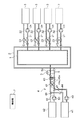
まずは、図1に基づいて熱利用システムの全体構成を説明する。
この熱利用システムは、複数の熱利用部3と、複数の熱利用部3の夫々に高温の熱源水(高温用設定温度の熱源水)を供給自在な高温系統1と、複数の熱利用部3の夫々に低温の熱源水(低温用設定温度の熱源水)を供給自在な低温系統2と、高温系統1及び低温系統2の熱源水を温調自在な熱源部4とを備えている。
First, the overall configuration of the heat utilization system will be described with reference to FIG.
The heat utilization system includes a plurality of heat utilization units 3, a high temperature system 1 capable of supplying high-temperature heat source water (heat source water having a high temperature setting temperature) to each of the plurality of heat utilization units 3, and a plurality of heat utilization units. 3 includes a low-temperature system 2 that can supply low-temperature heat source water (heat source water having a low temperature setting temperature) to each of the three, and a heat source unit 4 that can adjust the temperature of the heat source water of the high-temperature system 1 and the low-temperature system 2.
熱利用部3は、例えば、建物に設置される空調装置にて構成されており、1つの空調装置を熱利用部3として構成したり、建物全体又はある領域における複数の空調装置を熱利用部3として構成することができる。高温系統1には、複数の熱利用部3が並列的に接続され、ループ状に形成された高温系統1の熱源水を全ての熱利用部3に対して供給自在に構成されている。同様に、低温系統2には、複数の熱利用部3が並列的に接続され、ループ状に形成された低温系統2の熱源水を全ての熱利用部3に対して供給自在に構成されている。 The heat utilization unit 3 is constituted by, for example, an air conditioner installed in a building, and one air conditioner is configured as the heat utilization unit 3, or a plurality of air conditioners in a whole building or a certain area are used as the heat utilization unit. 3 can be configured. A plurality of heat utilization units 3 are connected to the high temperature system 1 in parallel, and the heat source water of the high temperature system 1 formed in a loop shape can be supplied to all the heat utilization units 3. Similarly, a plurality of heat utilization units 3 are connected to the low temperature system 2 in parallel, and the heat source water of the low temperature system 2 formed in a loop shape is configured to be freely supplied to all the heat utilization units 3. Yes.
複数の熱利用部3の夫々は、高温系統1の熱源水を高温系統1から取り込んで熱利用し、利用後の熱源水を低温系統2に供給する高温利用状態と、低温系統2の熱源水を低温系統2から取り込んで熱利用し、利用後の熱源水を高温系統1に供給する低温利用状態とに切換自在に構成されている。例えば、熱利用部3は、高温利用状態において、高温系統1の熱源水を温熱源として利用する暖房運転を行い、低温利用状態において、低温系統2の熱源水を冷熱源として利用する冷房運転を行う。 Each of the plurality of heat utilization units 3 takes in the heat source water of the high temperature system 1 from the high temperature system 1 and uses the heat, and uses the heat source water after utilization to the low temperature system 2 and the heat source water of the low temperature system 2 Can be switched from the low temperature system 2 to the low temperature utilization state in which the heat source water after utilization is supplied to the high temperature system 1. For example, the heat utilization unit 3 performs a heating operation using the heat source water of the high temperature system 1 as a heat source in the high temperature utilization state, and performs a cooling operation using the heat source water of the low temperature system 2 as the cooling heat source in the low temperature utilization state. Do.
複数の熱利用部3の夫々において、高温系統1及び低温系統2の系統からの熱源水を熱利用部3に供給する往路31と、熱利用部3にて熱利用後の熱源水を高温系統1及び低温系統2の系統に戻す復路32と、高温系統1及び低温系統2の系統に対する往路31及び復路32の接続状態を切り換える熱利用側切換弁33と、熱利用部3に供給する熱源水の流量を調整する流量調整ポンプ34(流量調整部に相当する)とが備えられている。
In each of the plurality of heat utilization units 3, the
熱利用側切換弁33は、往路31を高温系統1に接続し且つ復路32を低温系統2に接続する高温供給状態と、往路31を低温系統2に接続し且つ復路32を高温系統1に接続する低温供給状態とに切換自在に構成されている。そして、熱利用部3を高温利用状態に切り換える場合には、熱利用側切換弁33を高温供給状態に切り換え、熱利用部3を低温利用状態に切り換える場合には、熱利用側切換弁33を低温供給状態に切り換えている。
The heat utilization
流量調整ポンプ34は、例えば、その出力を調整することで、熱利用部3に供給する熱源水の流量を調整自在に構成されている。そして、流量調整ポンプ34は、熱利用部3での熱負荷の大きさに応じて、熱利用部3に供給する熱源水の流量を調整するように構成されている。つまり、流量調整ポンプ34は、熱利用部3の熱負荷が大きい程、熱利用部3に供給する熱源水の流量を増大させている。
The flow
熱源部4は、高温系統1側の熱源水を冷却して低温系統2側に供給する冷却作動、及び、低温系統2側の熱源水を加熱して高温系統1側に供給する加熱作動を実行可能に構成されている。 The heat source unit 4 performs a cooling operation for cooling the heat source water on the high temperature system 1 side and supplying it to the low temperature system 2 side, and a heating operation for heating the heat source water on the low temperature system 2 side and supplying it to the high temperature system 1 side It is configured to be possible.
高温系統1又は低温系統2の熱源水を熱源部4に供給するために、一端側が高温系統1に接続され且つ他端側が低温系統2に接続された分岐路5が備えられ、その分岐路5における熱源水の流通状態、熱源水の温度、及び、熱源水の流量を検出する熱源水検出部6(熱源水流通状態検出部、熱源水温度検出部、及び、熱源水流量検出部に相当する)が備えられている。
In order to supply the heat source water of the high temperature system 1 or the low temperature system 2 to the heat source unit 4, a
分岐路5は、高温系統1側又は低温系統2側から熱源水が熱源部4に供給される熱源部4側に配置され、その熱源水の一部を分岐流通させて低温系統2側又は高温系統1側に供給するように構成されている。熱源水が高温系統1側から分岐路5に流通する場合には、分岐路5が、その熱源水を熱源部4に供給し、熱源部4を通過した熱源水を低温系統2側に供給する。逆に、熱源水が低温系統2側から分岐路5に流通する場合には、分岐路5が、その熱源水を熱源部4に供給し、熱源部4を通過した熱源水を高温系統1側に供給する。
The
熱源水検出部6は、例えば、熱量計にて構成されており、一端部が分岐路5の一方側に接続され且つ他端部が分岐路5の他方側に接続された検出用流路6aにおける熱源水の温度、及び、熱源水の流量に加えて、熱源水の流通状態として、分岐路5における熱源水の流れの有無、及び、その流れ方向等を検出している。ちなみに、熱源水検出部6は、熱量計に限らず、熱源水の流通状態を検出する流通状態用の検出センサと、熱源水の温度を検出する温度用の検出センサと、熱源水の流量を検出する流量用の検出センサとを各別に備えて構成することもできる。
The heat source water detection unit 6 is configured by, for example, a calorimeter, and has a detection flow path 6 a in which one end is connected to one side of the
熱源部4は、熱源として、未利用エネルギーを用いる未利用エネルギー熱源41と補助熱源42とが備えられている。未利用エネルギーは、例えば、地中熱、河川水熱、下水熱、温度の低い外気から冷却塔等により生成される冷熱等、これまで使用されていなかった各種の熱を適用することができる。ちなみに、未利用エネルギー熱源41として、複数の熱源が存在する場合には、複数の熱源のうち、どの熱源を利用するかを選択自在に構成されており、例えば、熱搬送体をどのような温度に加熱又は冷却させるかによって、どの熱源を利用するかを選択できる。
The heat source unit 4 includes an unused
熱源部4は、熱源から循環供給される熱搬送体と熱源水とを熱交換させる熱源用熱交換部43と、未利用エネルギー熱源41から熱源用熱交換部43に熱搬送体を循環供給させる未利用側循環供給路44と、補助熱源42から熱源用熱交換部43に熱搬送体を循環供給させる補助側循環供給路45とを備えている。
The heat source unit 4 circulates and supplies the heat carrier to the heat source
未利用エネルギー熱源41及び補助熱源42は、冷却作動において、低温の熱搬送体にて冷熱を熱源用熱交換部43に供給する冷熱供給状態に切り換えられ、加熱作動において、高温の熱搬送体にて温熱を熱源用熱交換部43に供給する温熱供給状態に切り換えられる。
In the cooling operation, the unused
熱源用熱交換部43は、一方側が高温系統1に接続され、他方側が低温系統2に接続されている。高温系統1側から熱源用熱交換部43に熱源水が流通する場合には、その熱源水を熱源用熱交換部43にて熱交換し、熱交換後の熱源水を低温系統2側に供給する。逆に、低温系統2側から熱源用熱交換部43に熱源水が流通する場合には、その熱源水を熱源用熱交換部43にて熱交換し、熱交換後の熱源水を高温系統1側に供給する。
The heat source
未利用側循環供給路44には、未利用エネルギー熱源41から熱源用熱交換部43に循環供給する熱搬送体の流量を調整する未利用側流量調整ポンプ49(熱搬送体流量調整部に相当する)が備えられている。補助側循環供給路45には、補助熱源42から熱源用熱交換部43に循環供給する熱搬送体の流量を調整する補助側流量調整ポンプ50(熱搬送体流量調整部に相当する)が備えられている。
In the unused side
未利用側循環供給路44と補助側循環供給路45とは、熱源用熱交換部43に接続される流路部位が兼用の接続流路部位44a、45aにて構成されている。そして、兼用の接続流路部位44a、45aの端部には、第1三方弁46、第2三方弁47が備えられている。この第1三方弁46及び第2三方弁47によって、未利用側循環供給路44にて未利用エネルギー熱源41から熱源用熱交換部43に熱搬送体を循環供給させる未利用側供給状態と、補助側循環供給路45にて補助熱源42から熱源用熱交換部43に熱搬送体を循環供給させる補助側供給状態と、未利用側循環供給路44にて未利用エネルギー熱源41から熱源用熱交換部43に熱搬送体を循環供給させるとともに、補助側循環供給路45にて補助熱源42から熱源用熱交換部43に熱搬送体を循環供給させる併用利用状態とに切換自在に構成されている。
The unused-side
兼用の接続流路部位44a、45aには、熱源用熱交換部43における熱搬送体の流通方向を切り換える熱源側切換弁48が備えられている。この熱源側切換弁48によって熱搬送体の流通方向を切り換えることで、熱源用熱交換部43において、未利用エネルギー熱源41及び補助熱源42から供給される熱搬送体と熱源水とが対向して流通する状態で熱交換するように構成されている。
The shared connection
以下、熱利用システムの運転形態について説明する。
熱利用システムには、熱源部4等の作動状態を制御する制御部7が備えられている。
複数の熱利用部3の夫々は、暖房要求があると高温利用状態に切り換えて暖房負荷を賄うように運転し、冷房要求があると低温利用状態に切り換えて冷房負荷を賄うように運転している。制御部7は、複数の熱利用部3において暖房負荷と冷房負荷のどちらが大きいかやその熱負荷の大きさ等、複数の熱利用部3の全体での熱の利用状況がどのような状況となっているかを把握して、熱源部4の作動状態を制御している。熱の利用状況が異なる図1〜図5に基づいて説明する。
Hereinafter, the operation mode of the heat utilization system will be described.
The heat utilization system includes a control unit 7 that controls the operating state of the heat source unit 4 and the like.
When there is a heating request, each of the plurality of heat utilization units 3 is operated so as to cover the heating load by switching to the high temperature utilization state, and is operated so as to cover the cooling load by switching to the low temperature utilization state when there is a cooling request. Yes. The control unit 7 determines the state of heat utilization in the plurality of heat utilization units 3 such as which one of the heating load and the cooling load is larger in the plurality of heat utilization units 3 and the size of the heat load. The operation state of the heat source unit 4 is controlled by grasping whether or not it is. It demonstrates based on FIGS. 1-5 from which the utilization condition of heat differs.
夏期及び冬期を除く、中間期等では、ある箇所では暖房要求があり、別の箇所では冷房要求があるように、暖房要求と冷房要求とが混在している場合がある。まずは、暖房要求と冷房要求とが混在している場合について、図1〜図3に基づいて説明する。 In intermediate periods other than summer and winter, there are cases where heating requests and cooling requests are mixed so that there is a heating request in one place and a cooling request in another place. First, the case where a heating request | requirement and a cooling request | requirement are mixed is demonstrated based on FIGS. 1-3.
高温利用状態の熱利用部3では、熱利用側切換弁33を高温供給状態に切り換え、流量調整ポンプ34を作動させて、高温系統1の熱源水を取り込んで熱利用し、利用後の熱源水を低温系統2に供給する。このとき、流量調整ポンプ34は、その熱利用部3の熱負荷が大きい程、その熱利用部3に供給する熱源水の流量を増大させる形態で、熱利用部3での熱負荷の大きさに応じて、熱利用部3に供給する熱源水の流量を調整している。
In the heat utilization part 3 in the high temperature utilization state, the heat utilization
逆に、低温利用状態の熱利用部3では、熱利用側切換弁33を低温供給状態に切り換え、流量調整ポンプ34を作動させて、低温系統2の熱源水を取り込んで熱利用し、利用後の熱源水を高温系統1に供給する。このとき、流量調整ポンプ34は、その熱利用部3の熱負荷が大きい程、その熱利用部3に供給する熱源水の流量を増大させる形態で、熱利用部3での熱負荷の大きさに応じて、熱利用部3に供給する熱源水の流量を調整している。
On the other hand, in the heat utilization section 3 in the low temperature utilization state, the heat utilization
ここで、図1では、低温利用状態の熱利用部3(図中上方側に位置する3つの熱利用部3)と高温利用状態の熱利用部3(図中一番下方側に位置する1つの熱利用部3)とが混在して、冷房負荷が暖房負荷よりも大きい場合を示している。 Here, in FIG. 1, the heat utilization part 3 (three heat utilization parts 3 located in the upper side in the figure) in the low temperature utilization state and the heat utilization part 3 (one located in the lowermost part in the figure) in the high temperature utilization state. It shows a case where two heat utilization units 3) are mixed and the cooling load is larger than the heating load.
この場合には、冷房負荷が暖房負荷よりも大きいので、低温系統2から低温利用状態の熱利用部3に取り込まれて高温系統1に供給される熱源水の量が、高温系統1から高温利用状態の熱利用部3に取り込まれて低温系統2に供給される熱源水の量よりも多くなる。これにより、高温系統1の熱源水の量が増加し、低温系統2の熱源水の量が減少するので、分岐路5に対して、高温系統1側から低温系統2側に向けて熱源水が流通し、高温系統1の熱源水が分岐路5にて熱源部4の熱源用熱交換部43に供給される。そこで、熱源水検出部6が、高温系統1側から低温系統2側へ熱源水が流通していることを検出すると、制御部7は、熱源41、42を冷熱供給状態に切り換えて、熱源部4を冷却作動させる。
In this case, since the cooling load is larger than the heating load, the amount of heat source water taken from the low temperature system 2 into the heat utilization unit 3 in the low temperature utilization state and supplied to the high temperature system 1 is utilized from the high temperature system 1 at a high temperature. It becomes larger than the amount of heat source water taken into the heat utilization unit 3 in the state and supplied to the low temperature system 2. As a result, the amount of heat source water in the high temperature system 1 increases and the amount of heat source water in the low temperature system 2 decreases, so that the heat source water flows from the high temperature system 1 side to the low temperature system 2 side with respect to the
制御部7は、熱源部4を冷却作動させるに当たり、熱源水検出部6にて検出する熱源水の温度に基づいて、未利用エネルギー熱源41を補助熱源42よりも優先して利用する形態で、熱源部4の作動状態を制御する。図1では、未利用エネルギー熱源41を利用して、熱源部4を冷却作動させた場合を示している。
The control unit 7 uses the unused
未利用エネルギー熱源41では、各種の条件によって、その熱源の温度がどのような温度となっているかが変化する場合があることから、温度検出部等を用いて、熱源の温度等の熱情報が管理されている。そこで、制御部7は、未利用エネルギー熱源41の熱情報を取得し、その熱情報と熱源水検出部6にて検出する熱源水の温度とを比較して、未利用エネルギー熱源41を利用できるか否かを判別している。
In the unused
制御部7は、例えば、未利用エネルギー熱源41の温度が熱源水検出部6にて検出する熱源水の温度未満であれば、未利用エネルギー熱源41を利用できると判別して、第1三方弁46及び第2三方弁47により未利用側供給状態に切り換える。この未利用側供給状態では、未利用側流量調整ポンプ49を作動させ、未利用側循環供給路44にて未利用エネルギー熱源41から熱源用熱交換部43に熱搬送体を循環供給させて、熱源用熱交換部43において未利用エネルギー熱源41の冷熱を有する熱搬送体にて熱源水を冷却する。
For example, if the temperature of the unused
また、制御部7は、例えば、未利用エネルギー熱源41の温度が熱源水検出部6にて検出する熱源水の温度以上であれば、未利用エネルギー熱源41を利用できないと判別して、第1三方弁46及び第2三方弁47により補助側供給状態に切り換える。この補助側供給状態では、補助側流量調整ポンプ50を作動させ、補助側循環供給路45にて補助熱源42から熱源用熱交換部43に熱搬送体を循環供給させて、熱源用熱交換部43において補助熱源42の冷熱を有する熱搬送体にて熱源水を冷却する。
For example, if the temperature of the unused
制御部7は、熱源水検出部6にて高温系統1側から低温系統2側へ熱源水が流通していることを検出した当初だけでなく、その後、設定周期が経過するごとに、未利用エネルギー熱源41の熱情報と熱源水検出部6にて検出する熱源水の温度とを比較して、未利用エネルギー熱源41を利用できるか否かを判別する処理を繰り返し行うこともできる。この繰り返しによって、補助熱源42を利用している状態のときに未利用エネルギー熱源41を利用できる状態に変化すると、その状態変化に応じて、未利用エネルギー熱源41を利用する状態に切り換えることができる。
Not only at the beginning when the heat source water detection unit 6 detects that the heat source water is circulating from the high temperature system 1 side to the low temperature system 2 side, but the controller 7 is not used every time the set cycle elapses. The process of determining whether or not the unused
上述の如く、未利用エネルギー熱源41のみを利用する単独利用状態と補助熱源42のみを利用する単独利用状態とに切り換えるものに限らず、例えば、未利用エネルギー熱源41を利用できる場合に、未利用エネルギー熱源41と補助熱源42とを利用する併用利用状態とすることもできる。この場合には、制御部7が、未利用側流量調整ポンプ49及び補助側流量調整ポンプ50を制御して、未利用エネルギー熱源41から熱源用熱交換部43に循環供給する熱搬送体の流量を、補助熱源42から熱源用熱交換部43に循環供給する熱搬送体の流量よりも多くすることで、未利用エネルギー熱源41を補助熱源42よりも優先して利用できる。
As described above, the present invention is not limited to the single use state in which only the unused
制御部7は、熱源部4を冷却作動させるに当たり、熱源水検出部6にて検出する熱源水の流量に基づいて、熱源41、42から熱源用熱交換部43に循環供給する熱搬送体の流量を調整するように未利用側流量調整ポンプ49及び補助側流量調整ポンプ50を制御している。
When the heat source unit 4 is cooled, the control unit 7 circulates heat from the
熱源水検出部6にて検出する熱源水の流量が多くなる程、熱源用熱交換部43に流通する熱源水も多くなるので、未利用エネルギー熱源41を利用している場合には、制御部7が、未利用側流量調整ポンプ49の出力を増大させて、未利用エネルギー熱源41から熱源用熱交換部43に循環供給する熱搬送体の流量を増加させる。補助熱源42を利用している場合には、制御部7が、補助側流量調整ポンプ50の出力を増大させて、補助熱源42から熱源用熱交換部43に循環供給する熱搬送体の流量を増加させている。このように、熱源用熱交換部43には、流通する熱源水の流量に対して、熱交換するのに十分な流量の熱搬送体を過不足なく供給でき、熱源水と熱搬送体との熱交換を適切に行える。
As the flow rate of the heat source water detected by the heat source water detection unit 6 increases, the heat source water flowing through the heat source
また、制御部7は、熱源部4を冷却作動させるに当たり、熱源側切換弁48によって熱源用熱交換部43における熱搬送体の流通方向を調整している。制御部7は、熱源用熱交換部43における高温系統1側から低温系統2側への熱源水の流通方向に対して、熱源41、42からの熱搬送体の流通方向が対向するように、熱源側切換弁48を切り換えている。
In addition, when the heat source unit 4 is cooled, the control unit 7 adjusts the flow direction of the heat transfer body in the heat source
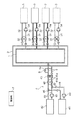
図2では、高温利用状態の熱利用部3(図中上方側に位置する3つの熱利用部3)と低温利用状態の熱利用部3(図中一番下方側に位置する1つの熱利用部3)とが混在して、暖房負荷が冷房負荷よりも大きい場合を示している。このときの熱利用部3の動作については上述の動作と同様である。 In FIG. 2, the heat utilization part 3 in the high temperature utilization state (three heat utilization parts 3 located on the upper side in the figure) and the heat utilization part 3 in the low temperature utilization state (one heat utilization located on the lowermost side in the figure) Part 3) is mixed and the heating load is larger than the cooling load. The operation of the heat utilization unit 3 at this time is the same as that described above.
この場合には、暖房負荷が冷房負荷よりも大きいので、高温系統1から高温利用状態の熱利用部3に取り込まれて低温系統2に供給される熱源水の量が、低温系統2から低温利用状態の熱利用部3に取り込まれて高温系統1に供給される熱源水の量よりも多くなる。これにより、低温系統2の熱源水の量が増加し、高温系統1の熱源水の量が減少するので、分岐路5に対して、低温系統2側から高温系統1側に向けて熱源水が流通し、低温系統1の熱源水が分岐路5にて熱源部4の熱源用熱交換部43に供給される。そこで、熱源水検出部6が、低温系統2側から高温系統1側へ熱源水が流通していることを検出すると、制御部7は、熱源41、42を温熱供給状態に切り換えて、熱源部4を加熱作動させる。
In this case, since the heating load is larger than the cooling load, the amount of heat source water taken from the high temperature system 1 into the heat utilization unit 3 in the high temperature utilization state and supplied to the low temperature system 2 is low temperature utilization from the low temperature system 2. It becomes larger than the amount of heat source water taken into the heat utilization unit 3 in the state and supplied to the high temperature system 1. As a result, the amount of heat source water in the low temperature system 2 increases and the amount of heat source water in the high temperature system 1 decreases, so that the heat source water flows from the low temperature system 2 side to the high temperature system 1 side with respect to the
制御部7は、冷却作動と同様に、熱源部4を加熱作動させるに当たり、熱源水検出部6にて検出する熱源水の温度に基づいて、未利用エネルギー熱源41を補助熱源42よりも優先して利用する形態で、熱源部4の作動状態を制御するとともに、熱源水検出部6にて検出する熱源水の流量に基づいて、熱源41、42から熱源用熱交換部43に循環供給する熱搬送体の流量を調整するように未利用側流量調整ポンプ49及び補助側流量調整ポンプ50を制御している。図2では、未利用エネルギー熱源41を利用して、熱源部4を加熱作動させた場合を示している。
Similar to the cooling operation, the control unit 7 prioritizes the unused
また、制御部7は、熱源部4を加熱作動させるに当たり、熱源用熱交換部43における熱源41、42からの熱搬送体の流通方向が冷却作動させる場合とは反対方向となるように、熱源側切換弁48を切り換えている。これにより、熱源部4を加熱作動させる場合も、熱源用熱交換部43における低温系統2側から高温系統1側への熱源水の流通方向に対して、熱源41、42からの熱搬送体の流通方向が対向するようにしている。
In addition, when the control unit 7 performs the heating operation of the heat source unit 4, the heat source
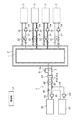
図3では、高温利用状態の熱利用部3(図中上方側から2番目と一番下方側に位置する2つの熱利用部3)と低温利用状態の熱利用部3(図中一番上方側と上方側から3番目に位置する2つの熱利用部3)とが混在して、冷房負荷と暖房負荷とが同じ又は略同じ場合を示している。このときの熱利用部3の動作については上述の動作と同様である。 In FIG. 3, the heat utilization part 3 in the high temperature utilization state (the two heat utilization parts 3 located second and lowest on the upper side in the figure) and the heat utilization part 3 in the low temperature utilization state (the uppermost part in the figure) The case where two heat utilization parts 3) located third from the side and the upper side are mixed and the cooling load and the heating load are the same or substantially the same is shown. The operation of the heat utilization unit 3 at this time is the same as that described above.
この場合には、冷房負荷と暖房負荷とが同じ又は略同じであるので、低温系統2から低温利用状態の熱利用部3に取り込まれて高温系統1に供給される熱源水の量と、高温系統1から高温利用状態の熱利用部3に取り込まれて低温系統2に供給される熱源水の量とが同じ又は略同じになる。これにより、高温系統1及び低温系統2の両系統とも熱源水の量が変化しないので、分岐路5に対して、熱源水の流通が無い状態となる。そこで、熱源水検出部6が、熱源水の流通が無い状態を検出していると、制御部7は、熱源部4を作動停止させたままとする。よって、熱源部4を作動させないことから、消費エネルギーの低減を図ることができ、省エネルギー化を図ることができる。
In this case, since the cooling load and the heating load are the same or substantially the same, the amount of heat source water taken into the heat utilization unit 3 in the low temperature utilization state from the low temperature system 2 and supplied to the high temperature system 1 and the high temperature The amount of heat source water taken from the system 1 into the heat utilization unit 3 in the high temperature utilization state and supplied to the low temperature system 2 is the same or substantially the same. Thereby, since the quantity of heat source water does not change in both the high temperature system 1 and the low temperature system 2, the heat source water does not flow through the
この場合には、熱源水の流れとして、高温系統1から高温利用状態の熱利用部3に熱源水が取り込まれ、利用後の熱源水が低温系統2に供給され、その利用後の熱源水が低温系統2から低温利用状態の熱利用部3に取り込まれるだけの流れとなる。つまり、熱源水は、熱源部4に供給されることなく、高温系統1、高温利用状態の熱利用部3、低温系統2、低温利用状態の熱利用部3、高温系統1の順に循環される。 In this case, as the heat source water flow, the heat source water is taken from the high temperature system 1 into the heat utilization unit 3 in the high temperature utilization state, the utilized heat source water is supplied to the low temperature system 2, and the heat source water after utilization is The flow is merely taken from the low-temperature system 2 into the heat utilization unit 3 in the low-temperature utilization state. That is, the heat source water is circulated in the order of the high temperature system 1, the high temperature utilization state heat utilization unit 3, the low temperature utilization state 2, the low temperature utilization state heat utilization unit 3, and the high temperature system 1 without being supplied to the heat source unit 4. .
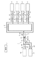
例えば、夏期には、空調要求としては冷房要求だけとなる。図4では、高温利用状態の熱利用部3が無く、低温利用状態の熱利用部3のみが存在する場合を示している。このときの低温利用状態の熱利用部3の動作については上述の動作と同様である。 For example, in the summer, the air conditioning request is only the cooling request. FIG. 4 shows a case where there is no heat utilization unit 3 in the high temperature utilization state and only the heat utilization unit 3 in the low temperature utilization state. The operation of the heat utilization unit 3 in the low temperature utilization state at this time is the same as the above-described operation.
この場合には、低温利用状態の熱利用部3と高温利用状態の熱利用部3とが混在して冷房負荷が暖房負荷よりも大きい場合を示す図1と同様に、分岐路5に対して、高温系統1側から低温系統2側に向けて熱源水が流通し、高温系統1の熱源水が分岐路5にて熱源用熱交換部43に供給される。そこで、熱源水検出部6が、高温系統1側から低温系統2側へ熱源水が流通していることを検出すると、制御部7は、熱源41、42を冷熱供給状態に切り換えて、熱源部4を冷却作動させる。熱源部4の冷却作動については、図1における動作と同様である。
In this case, with respect to the
例えば、冬期には、空調要求としては暖房要求だけとなる場合がある。図5では、低温利用状態の熱利用部3が無く、高温利用状態の熱利用部3のみが存在する場合を示している。このときの高温利用状態の熱利用部3の動作については上述の動作と同様である。 For example, in winter, there may be only a heating request as an air conditioning request. FIG. 5 shows a case where there is no heat utilization unit 3 in the low temperature utilization state and only the heat utilization unit 3 in the high temperature utilization state. The operation of the heat utilization unit 3 in the high temperature utilization state at this time is the same as the above-described operation.
この場合には、低温利用状態の熱利用部3と高温利用状態の熱利用部3とが混在して暖房負荷が冷房負荷よりも大きい場合を示す図2と同様に、分岐路5に対して、低温系統2側から高温系統1側に向けて熱源水が流通し、低温系統2の熱源水が分岐路5にて熱源用熱交換部43に供給される。そこで、熱源水検出部6が、低温系統2側から高温系統1側へ熱源水が流通していることを検出すると、制御部7は、熱源41、42を温熱供給状態に切り換えて、熱源部4を加熱作動させる。熱源部4の加熱作動については、図2における動作と同様である。
In this case, as with FIG. 2 showing a case where the heat utilization unit 3 in the low temperature utilization state and the heat utilization unit 3 in the high temperature utilization state are mixed and the heating load is larger than the cooling load, The heat source water flows from the low temperature system 2 side to the high temperature system 1 side, and the heat source water of the low temperature system 2 is supplied to the heat source
図1〜図5に示すように、複数の熱利用部3の全体において、暖房負荷と冷房負荷とのどちらかが大きい場合には、分岐路5において熱源水の流通が生じ、暖房負荷と冷房負荷とが同じ又は略同じ場合には、分岐路5において熱源水の流通が無い。また、暖房負荷と冷房負荷とのどちらが大きいかによって、分岐路5において、高温系統1側から低温系統2側に向かう流通方向の熱源水の流通が生じるのか、低温系統2側から高温系統1側に向かう流通方向の熱源水の流通が生じるのかが変化する。よって、分岐路5及び熱源水検出部6を備えることで、熱源用熱交換部43における熱源水の流通の有無、及び、その流通方向を適切に検出することができる。制御部7は、熱源水検出部6の検出情報に基づいて、熱源部4の作動状態を制御することで、無駄に熱源部4を作動させることもなく、省エネルギー化を図りながら、熱源部4の作動状態を適切に制御できる。
As shown in FIGS. 1 to 5, when one of the heating load and the cooling load is large in the whole of the plurality of heat utilization units 3, the heat source water flows in the
高温系統1と低温系統2とは、熱源部4における熱源用熱交換部43を挟んで分離されているので、高温系統1の熱源水と低温系統2の熱源水とが混合して温度が変化するミキシングロスを抑制でき、省エネルギー化を図ることができる。
Since the high temperature system 1 and the low temperature system 2 are separated with the heat source
ここで、熱源部4を冷却作動させる場合に、制御部7が、熱源水が低温用設定温度になるように熱源部4の作動状態を制御できる。また、熱源部4を加熱作動させる場合に、制御部7が、熱源水が高温用設定温度になるように熱源部4の作動状態を制御できる。このように、熱源部4の冷却作動によって、熱源水を低温用設定温度に冷却させると、低温系統2の熱源水の温度を低温用設定温度に調整することができ、熱源部4の加熱作動によって、熱源水を高温用設定温度に加熱させると、高温系統1の熱源水の温度を高温用設定温度に調整することができる。よって、高温利用状態の熱利用部3には、高温用設定温度の熱源水を供給することができ、高温利用状態の熱利用部3における熱利用を安定して行えるとともに、低温利用状態の熱利用部3には、低温用設定温度の熱源水を供給することができ、低温利用状態の熱利用部3における熱利用を安定して行える。 Here, when the heat source unit 4 is cooled, the control unit 7 can control the operation state of the heat source unit 4 so that the heat source water becomes the set temperature for low temperature. Further, when the heat source unit 4 is heated and operated, the control unit 7 can control the operation state of the heat source unit 4 so that the heat source water becomes the set temperature for high temperature. As described above, when the heat source water is cooled to the low temperature set temperature by the cooling operation of the heat source unit 4, the temperature of the heat source water of the low temperature system 2 can be adjusted to the low temperature set temperature, and the heat source unit 4 is heated. Thus, when the heat source water is heated to the set temperature for high temperature, the temperature of the heat source water of the high temperature system 1 can be adjusted to the set temperature for high temperature. Therefore, the heat utilization part 3 in the high temperature utilization state can be supplied with the heat source water at the set temperature for high temperature, the heat utilization in the heat utilization part 3 in the high temperature utilization state can be stably performed, and the heat in the low temperature utilization state The utilization unit 3 can be supplied with heat source water having a set temperature for low temperature, and the heat utilization in the heat utilization unit 3 in a low temperature utilization state can be stably performed.
そして、高温用設定温度及び低温用設定温度をどのような温度に設定するかは適宜変更が可能であり、高温用設定温度は、高温利用状態の熱利用部3にて温熱を熱利用するに当たり、効率の向上を図れる温度に設定することができ、低温用設定温度は、低温利用状態の熱利用部3にて温熱を熱利用するに当たり、効率の向上を図れる温度に設定することができる。 And what kind of temperature is set to the set temperature for high temperature and the set temperature for low temperature can be changed as appropriate. The set temperature for high temperature is used when heat is utilized in the heat utilization unit 3 in the high temperature utilization state. The temperature can be set to a temperature at which the efficiency can be improved, and the set temperature for low temperature can be set to a temperature at which the efficiency can be improved when the heat is used in the heat using unit 3 in the low temperature use state.
図1に示すように、暖房負荷と冷房負荷とが混合して冷房負荷が暖房負荷よりも大きい場合には、多数の低温利用状態の熱利用部3に対して冷却用設定温度の熱源水を供給することができる。よって、多数の低温利用状態の熱利用部3において効率が向上するので、システムの全体としても、効率の向上を図ることができる。また、図4に示すように、全ての熱利用部3が低温利用状態となる場合は、全ての熱利用部3において効率が向上するので、システムの全体として、効率の向上を図ることができる。 As shown in FIG. 1, when the heating load and the cooling load are mixed and the cooling load is larger than the heating load, the heat source water at the set temperature for cooling is supplied to the heat utilization units 3 in the low temperature utilization state. Can be supplied. Therefore, since the efficiency is improved in a large number of low-temperature utilization states, the efficiency of the entire system can be improved. Moreover, as shown in FIG. 4, when all the heat utilization parts 3 will be in a low temperature utilization state, since efficiency will improve in all the heat utilization parts 3, efficiency improvement can be aimed at as the whole system. .
図2に示すように、暖房負荷と冷房負荷とが混合して暖房負荷が冷房負荷よりも大きい場合には、多数の高温利用状態の熱利用部3に対して加熱用設定温度の熱源水を供給することができる。よって、多数の高温利用状態の熱利用部3において効率が向上するので、システムの全体としても、効率の向上を図ることができる。また、図5に示すように、全ての熱利用部3が高温利用状態となる場合は、全ての熱利用部3において効率が向上するので、システムの全体として、効率の向上を図ることができる。 As shown in FIG. 2, when the heating load and the cooling load are mixed and the heating load is larger than the cooling load, the heat source water at the set temperature for heating is supplied to the heat utilization units 3 in a high temperature utilization state. Can be supplied. Therefore, since efficiency improves in the heat utilization part 3 of many high temperature utilization states, improvement of efficiency can be aimed at also as the whole system. Moreover, as shown in FIG. 5, when all the heat utilization parts 3 will be in a high temperature utilization state, since efficiency improves in all the heat utilization parts 3, the efficiency of the whole system can be improved. .
高温用設定温度及び低温用設定温度は、常時、一定の温度に設定しておく必要はない。例えば、中間期には、高温用設定温度を第1温度、低温用設定温度を第2温度に設定し、冬期には、高温用設定温度を第1温度よりも高温の温度に設定し、夏期には、低温用設定温度を第2温度よりも低温の温度に設定することができる。このように、季節や複数の熱利用部3の全体における熱の利用状況等に応じて、変更設定することもできる。 The set temperature for high temperature and the set temperature for low temperature need not always be set to a constant temperature. For example, in the intermediate period, the high temperature set temperature is set to the first temperature and the low temperature set temperature is set to the second temperature. In the winter period, the high temperature set temperature is set to a temperature higher than the first temperature, and the summer period is set. In this case, the set temperature for low temperature can be set to a temperature lower than the second temperature. In this way, the setting can be changed according to the season and the heat utilization status of the plurality of heat utilization units 3 as a whole.
また、例えば、未利用エネルギー熱源41を利用するときの高温用設定温度を第1温度とし、補助熱源42を利用するときの高温用設定温度を第1温度よりも高温の温度に設定することもできる。このように、未利用エネルギー熱源41を利用するときの高温用設定温度と、補助熱源42を利用するときの高温用設定温度とを異なる温度に設定することもできる。そして、未利用エネルギー熱源41を利用するときの低温用設定温度と補助熱源42を利用するときの低温用設定温度とについても、高温用設定温度と同様に、必ずしも同じ温度に設定する必要はなく、未利用エネルギー熱源41を利用するときよりも補助熱源42を利用するときの方が低温の温度になるように設定する等、異なる温度を設定することもできる。
Further, for example, the set temperature for high temperature when using the unused
〔別実施形態〕
(1)上記実施形態では、熱源部4を冷却作動及び加熱作動させる場合に、常時、未利用エネルギー熱源41を利用する状態と補助熱源42を利用する状態とに切り換えているが、例えば、夏季や冬季には、補助熱源42のみを利用する状態とする等、季節や複数の熱利用部3における熱の利用状況等によって、未利用エネルギー熱源41を利用する状態と補助熱源42を利用する状態とに切り換えるときと、補助熱源42のみを利用するときとに場合分けすることもできる。
[Another embodiment]
(1) In the above embodiment, when the heat source unit 4 is cooled and heated, the state is always switched between the state of using the unused
(2)上記実施形態において、熱利用部3の数については、4つに限るものではなく、適宜変更が可能である。 (2) In the said embodiment, about the number of the heat utilization parts 3, it is not restricted to four, It can change suitably.
(3)上記実施形態では、熱源用熱交換部43を備えた例を示したが、この熱源用熱交換部43を備えずに、例えば、未利用エネルギー熱源41や補助熱源42にて熱源水を直接加熱又は冷却することもできる。
(3) In the above-described embodiment, an example in which the heat source
(4)上記実施形態では、分岐路5に備えた検出用流路6aに、熱源水検出部6としての熱量計を設けることで、分岐路5における熱源水の流通状態、熱源水の温度、熱源水の流量を検出している。これに代えて、例えば、分岐路5の一方側と他方側との両側に、熱源水の温度を検出する熱源水温度検出部を備えるとともに、分岐路5の一方側と他方側の少なくとも一方に、熱源水の流れの有無、及び、その流れ方向等の熱源水の流通状態と熱源水の流量とを検出する熱源水流通状態・熱源水流量検出部を備えることもできる。よって、検出用流路6aを備えずに、分岐路5において、直接、熱源水の流通状態、熱源水の温度、及び、熱源水の流量を検出することもできる。
(4) In the above embodiment, by providing a calorimeter as the heat source water detection unit 6 in the detection flow path 6a provided in the
1 高温系統
2 低温系統
3 熱利用部
4 熱源部
5 分岐路
6 熱源水検出部(熱源水流通状態検出部、熱源水温度検出部、熱源水流量検出部)
7 制御部
34 流量調整ポンプ(流量調整部)
41 未利用エネルギー熱源
42 補助熱源
43 熱源用熱交換部
49 未利用側流量調整ポンプ(熱搬送体流量調整部)
50 補助側流量調整ポンプ(熱搬送体流量調整部)
DESCRIPTION OF SYMBOLS 1 High temperature system 2 Low temperature system 3 Heat utilization part 4
7
41 Unused
50 Auxiliary flow rate adjustment pump (heat carrier flow rate adjustment part)
Claims (5)
前記複数の熱利用部の夫々に高温の熱源水を供給自在な高温系統と、
前記複数の熱利用部の夫々に低温の熱源水を供給自在な低温系統と、
前記高温系統側から供給される熱源水を冷却して前記低温系統側に供給する冷却作動、及び、前記低温系統側から供給される熱源水を加熱して前記高温系統側に供給する加熱作動を実行可能な熱源部とが備えられ、
前記複数の熱利用部の夫々は、前記高温系統の熱源水を利用して、利用後の熱源水を前記低温系統に供給する高温利用状態と、前記低温系統の熱源水を利用して、利用後の熱源水を前記高温系統に供給する低温利用状態とに切換自在に構成され、
前記高温系統側又は前記低温系統側から熱源水が前記熱源部に供給される熱源部側に配置され、その熱源水の一部を分岐流通させて前記低温系統側又は前記高温系統側に供給する分岐路と、
前記分岐路における熱源水の流通状態を検出する熱源水流通状態検出部と、
前記熱源水流通状態検出部の検出情報に基づいて、前記熱源部の作動状態を制御する制御部とが備えられている熱利用システム。 A heat utilization system having a plurality of heat utilization sections,
A high-temperature system capable of supplying high-temperature heat source water to each of the plurality of heat utilization units;
A low-temperature system capable of supplying low-temperature heat source water to each of the plurality of heat utilization units;
A cooling operation for cooling the heat source water supplied from the high temperature system side and supplying it to the low temperature system side, and a heating operation for heating the heat source water supplied from the low temperature system side and supplying it to the high temperature system side A feasible heat source,
Each of the plurality of heat use units uses the heat source water of the high temperature system, uses the heat source water after use to the low temperature system, and uses the heat source water of the low temperature system. It is configured to be switchable to a low temperature use state that supplies the heat source water to the high temperature system,
Heat source water is arranged from the high temperature system side or the low temperature system side to the heat source part side to be supplied to the heat source part, and a part of the heat source water is branched and supplied to the low temperature system side or the high temperature system side. A fork,
A heat source water flow state detection unit for detecting a flow state of the heat source water in the branch path;
The heat utilization system provided with the control part which controls the operating state of the said heat-source part based on the detection information of the said heat-source water circulation state detection part.
Priority Applications (1)
| Application Number | Priority Date | Filing Date | Title |
|---|---|---|---|
| JP2016026935A JP6697891B2 (en) | 2016-02-16 | 2016-02-16 | Heat utilization system |
Applications Claiming Priority (1)
| Application Number | Priority Date | Filing Date | Title |
|---|---|---|---|
| JP2016026935A JP6697891B2 (en) | 2016-02-16 | 2016-02-16 | Heat utilization system |
Publications (2)
| Publication Number | Publication Date |
|---|---|
| JP2017145986A true JP2017145986A (en) | 2017-08-24 |
| JP6697891B2 JP6697891B2 (en) | 2020-05-27 |
Family
ID=59681310
Family Applications (1)
| Application Number | Title | Priority Date | Filing Date |
|---|---|---|---|
| JP2016026935A Active JP6697891B2 (en) | 2016-02-16 | 2016-02-16 | Heat utilization system |
Country Status (1)
| Country | Link |
|---|---|
| JP (1) | JP6697891B2 (en) |
Citations (7)
| Publication number | Priority date | Publication date | Assignee | Title |
|---|---|---|---|---|
| JPH04113139A (en) * | 1990-09-04 | 1992-04-14 | Ebara Corp | District cooling/heating system |
| JP2000257938A (en) * | 1999-03-09 | 2000-09-22 | Dai-Dan Co Ltd | Controller for operating number of heat source |
| JP2002162087A (en) * | 2000-11-22 | 2002-06-07 | Dai-Dan Co Ltd | Variable flow control system for exhaust heat recovery and heat source |
| JP2006275323A (en) * | 2005-03-28 | 2006-10-12 | Sanki Eng Co Ltd | Heat source system optimal operation control method and device |
| JP2012530237A (en) * | 2009-06-16 | 2012-11-29 | ディーイーシー デザイン メカニカル コンサルタンツ リミテッド | Community energy sharing system |
| JP2014102025A (en) * | 2012-11-19 | 2014-06-05 | Osaka City Univ | Heat energy transport system, heat interchanging system, and heat energy transport method |
| JP2014190619A (en) * | 2013-03-27 | 2014-10-06 | Mitsubishi Heavy Ind Ltd | Heat source system, control device thereof and control method therefor |
-
2016
- 2016-02-16 JP JP2016026935A patent/JP6697891B2/en active Active
Patent Citations (7)
| Publication number | Priority date | Publication date | Assignee | Title |
|---|---|---|---|---|
| JPH04113139A (en) * | 1990-09-04 | 1992-04-14 | Ebara Corp | District cooling/heating system |
| JP2000257938A (en) * | 1999-03-09 | 2000-09-22 | Dai-Dan Co Ltd | Controller for operating number of heat source |
| JP2002162087A (en) * | 2000-11-22 | 2002-06-07 | Dai-Dan Co Ltd | Variable flow control system for exhaust heat recovery and heat source |
| JP2006275323A (en) * | 2005-03-28 | 2006-10-12 | Sanki Eng Co Ltd | Heat source system optimal operation control method and device |
| JP2012530237A (en) * | 2009-06-16 | 2012-11-29 | ディーイーシー デザイン メカニカル コンサルタンツ リミテッド | Community energy sharing system |
| JP2014102025A (en) * | 2012-11-19 | 2014-06-05 | Osaka City Univ | Heat energy transport system, heat interchanging system, and heat energy transport method |
| JP2014190619A (en) * | 2013-03-27 | 2014-10-06 | Mitsubishi Heavy Ind Ltd | Heat source system, control device thereof and control method therefor |
Also Published As
| Publication number | Publication date |
|---|---|
| JP6697891B2 (en) | 2020-05-27 |
Similar Documents
| Publication | Publication Date | Title |
|---|---|---|
| US10525787B2 (en) | Electric vehicle thermal management system with series and parallel structure | |
| JP5174950B2 (en) | Temperature adjusting device, fluid supply system, heating system, temperature adjusting device mounting method, and fluid supply method | |
| US9395249B2 (en) | Wide range temperature control system for semiconductor manufacturing equipment using thermoelectric element | |
| CN104748308A (en) | Control method for loading and load shedding of optimized module machine system | |
| KR20140139425A (en) | Heating system | |
| JP2011043321A (en) | Heating medium supply device | |
| RU2013122264A (en) | SOURCE OF HEAT | |
| JP4934009B2 (en) | Heat source water supply system | |
| CA2757677C (en) | Control device for a heating system and heating system | |
| JP2016075425A (en) | Hot water supply system and operation control method of the same | |
| JP2007315621A (en) | Water cooled heat pump type air conditioning heat source device | |
| JP2016166718A (en) | Heat pump hot water supply heating system | |
| JP6570874B2 (en) | Heat storage system | |
| JP6663740B2 (en) | Heat utilization system | |
| EP2722596B1 (en) | Heating installation and method related thereto | |
| JP2017145986A (en) | Heat utilization system | |
| JP5192778B2 (en) | Hot water heater | |
| JP7008347B2 (en) | Hot water and energy storage | |
| JP2009236369A (en) | Absorption chiller/heater | |
| JP6109776B2 (en) | Electric instantaneous water heater system | |
| JP6668070B2 (en) | Heat utilization system | |
| KR101016717B1 (en) | Triple effect heat pump system | |
| JP7186121B2 (en) | heat source system | |
| CN101288036B (en) | Method for controlling and/or regulating room temperature in a building | |
| JP2019124396A (en) | Air conditioning system |
Legal Events
| Date | Code | Title | Description |
|---|---|---|---|
| A621 | Written request for application examination |
Free format text: JAPANESE INTERMEDIATE CODE: A621 Effective date: 20181220 |
|
| A977 | Report on retrieval |
Free format text: JAPANESE INTERMEDIATE CODE: A971007 Effective date: 20190926 |
|
| A131 | Notification of reasons for refusal |
Free format text: JAPANESE INTERMEDIATE CODE: A131 Effective date: 20191023 |
|
| A521 | Request for written amendment filed |
Free format text: JAPANESE INTERMEDIATE CODE: A523 Effective date: 20191213 |
|
| TRDD | Decision of grant or rejection written | ||
| A01 | Written decision to grant a patent or to grant a registration (utility model) |
Free format text: JAPANESE INTERMEDIATE CODE: A01 Effective date: 20200422 |
|
| A61 | First payment of annual fees (during grant procedure) |
Free format text: JAPANESE INTERMEDIATE CODE: A61 Effective date: 20200427 |
|
| R150 | Certificate of patent or registration of utility model |
Ref document number: 6697891 Country of ref document: JP Free format text: JAPANESE INTERMEDIATE CODE: R150 |