JP2017136143A - Game machine - Google Patents
Game machine Download PDFInfo
- Publication number
- JP2017136143A JP2017136143A JP2016017841A JP2016017841A JP2017136143A JP 2017136143 A JP2017136143 A JP 2017136143A JP 2016017841 A JP2016017841 A JP 2016017841A JP 2016017841 A JP2016017841 A JP 2016017841A JP 2017136143 A JP2017136143 A JP 2017136143A
- Authority
- JP
- Japan
- Prior art keywords
- effect
- button
- image
- special
- variable display
- Prior art date
- Legal status (The legal status is an assumption and is not a legal conclusion. Google has not performed a legal analysis and makes no representation as to the accuracy of the status listed.)
- Granted
Links
Images


Abstract
Description
本発明は、パチンコ遊技機等の遊技機に関する。 The present invention relates to a gaming machine such as a pachinko gaming machine.
遊技機として、遊技球などの遊技媒体を発射装置によって遊技領域に発射し、遊技領域に設けられている所定の入賞領域(始動入賞口)に遊技媒体が入賞する(始動条件が成立する)と識別情報を可変表示(「変動」ともいう)可能な可変表示装置が設けられ、可変表示装置において識別情報の可変表示の表示結果が特定表示結果(大当り図柄)となった場合に遊技者にとって有利な有利状態(特定遊技状態)に制御可能に構成されたものがある。 As a gaming machine, when a game medium such as a game ball is launched into a game area by a launching device, and the game medium wins in a predetermined prize area (start prize opening) provided in the game area (a start condition is satisfied). A variable display device capable of variably displaying the identification information (also referred to as “fluctuation”) is provided, and it is advantageous for the player when the display result of the variable display of the identification information in the variable display device becomes a specific display result (big hit symbol) Some advantageous states (specific game states) can be controlled.
このような遊技機として、画像表示装置の表示領域にボタン画像を重ねて表示し、表示されたボタン画像に対応した操作ボタンへの連打を遊技者に促す促進演出を実行する遊技機がある(例えば特許文献1)。 As such a gaming machine, there is a gaming machine that displays a button image superimposed on a display area of an image display device, and executes a promotion effect that prompts the player to hit the operation button corresponding to the displayed button image ( For example, Patent Document 1).
しかしながら、特許文献1に記載の遊技機では、同じ大きさのボタン画像を重ねて表示したり、異なる大きさのボタン画像を重ねて表示したりするだけであるので、演出効果に乏しいという問題があった。
However, in the gaming machine described in
この発明は、上記実状に鑑みてなされたものであり、演出効果を向上させることができる遊技機の提供を目的とする。 This invention is made in view of the said actual condition, and aims at provision of the gaming machine which can improve a production effect.
(1)上記目的を達成するため、本願発明に係る遊技機は、
遊技が可能な遊技機(例えば、パチンコ遊技機1など)であって、
動作促進画像(例えば、ボタン画像やレバー画像など)を表示する画像表示手段(例えば、画像表示装置5など)を備え、
前記動作促進画像は、遊技者の第1動作(例えば、押下操作など)を促す第1促進画像(例えば、ボタン画像など)と、該第1促進画像とは異なる画像であって遊技者の第2動作(例えば、傾倒操作など)を促す第2促進画像(例えば、レバー画像など)と、を含み、
前記画像表示手段は、複数の前記第1促進画像と、前記第2促進画像と、を重ねて表示する(例えば、レバー画像の上に4つのボタン画像を被せて表示するなど、図21、図22を参照)、
ことを特徴とする。
(1) In order to achieve the above object, a gaming machine according to the present invention provides:
A gaming machine capable of playing a game (for example, pachinko gaming machine 1),
Image display means (for example, the
The action promotion image is an image different from the first promotion image (for example, button image) that prompts the player's first action (for example, pressing operation) and the first promotion image, and is the player's first action image. A second promotion image (for example, a lever image) that prompts two actions (for example, tilting operation)
The image display means displays a plurality of the first promotion images and the second promotion images so as to overlap each other (for example, display four button images on the lever image, etc.). 22),
It is characterized by that.
このような構成によれば、演出効果を向上させることができる。 According to such a configuration, it is possible to improve the effect.
(2)上記(1)の遊技機において、
前記画像表示手段は、前記第2促進画像を視認可能に表示した後に、複数の前記第1促進画像を表示する(例えば、図18、図21、図22を参照)、
ことを特徴とする。
(2) In the gaming machine of (1) above,
The image display means displays the plurality of first promotion images after displaying the second promotion images so as to be visible (see, for example, FIGS. 18, 21, and 22).
It is characterized by that.
このような構成によれば、演出効果を向上させることができる。 According to such a configuration, it is possible to improve the effect.
(3)上記(1)または(2)の遊技機において、
前記第1動作と前記第2動作とを検出可能な検出手段(例えば、プッシュボタン31B及びスティックコントローラ31Aなど)をさらに備え、
前記第1動作の検出を有効とした後に、前記第2動作の検出を有効とする(例えば、ステップS623にてプッシュボタン31Bの操作有効期間を開始させるための設定を行った後、ステップS625〜S636の処理を行い、ステップS604にてスティックコントローラ31Aの操作有効期間を開始させるための設定を行う)、
ことを特徴とする。
(3) In the above gaming machine (1) or (2),
It further comprises detection means (for example, a
After the detection of the first action is enabled, the detection of the second action is enabled (for example, after setting for starting the operation valid period of the
It is characterized by that.
このような構成によれば、演出効果を向上させることができる。 According to such a configuration, it is possible to improve the effect.
(4)上記(3)の遊技機において、
前記第1動作が検出されたことにもとづいて、前記第1促進画像を消去可能であり(例えば、ステップS626にてボタン操作の検出ありと判定されたことにもとづいて、ステップS631の処理(画像表示装置5からボタン画像を1つ消去する処理)を実行可能である)、
複数の前記第1促進画像が消去されたときに、前記第2動作の検出を有効とする(例えば、ステップS633にてボタン操作カウンタのカウント値が「0」であると判定された場合に、ステップS634〜S636の処理を行い、ステップS604にてスティックコントローラ31Aの操作有効期間を開始させるための設定を行う)、
ことを特徴とする。
(4) In the gaming machine of (3) above,
The first accelerated image can be erased based on the detection of the first action (for example, the process of step S631 (image based on the determination that button operation is detected in step S626). Processing to delete one button image from the display device 5),
When the plurality of first promotion images are erased, the detection of the second action is enabled (for example, when it is determined in step S633 that the count value of the button operation counter is “0”, Steps S634 to S636 are performed, and setting for starting the operation valid period of the
It is characterized by that.
このような構成によれば、演出効果を向上させることができる。 According to such a configuration, it is possible to improve the effect.
(5)上記(1)から(4)のいずれかの遊技機において、
前記画像表示手段は、前記動作促進画像として、前記第2促進画像を単独で表示することもあり(例えば、操作演出Bなど、図20を参照)、
前記動作促進画像として、前記第2促進画像が単独で表示されるときと、前記第1促進画像と前記第2促進画像とが重ねられて表示されるときとで、期待度が異なる(例えば、操作演出Cが実行されたときに大当り期待度が最も高く、操作演出Bが実行されたときに大当り期待度が次に高くなる、図11(B)を参照)、
ことを特徴とする。
(5) In any of the above gaming machines (1) to (4),
The image display means may display the second promotion image alone as the operation promotion image (for example, operation effect B, see FIG. 20),
As the motion promotion image, the degree of expectation differs between when the second promotion image is displayed alone and when the first promotion image and the second promotion image are superimposed and displayed (for example, When the operation effect C is executed, the jackpot expectation is the highest, and when the operation effect B is executed, the jackpot expectation is the next highest (see FIG. 11B).
It is characterized by that.
このような構成によれば、演出効果を向上させることができる。 According to such a configuration, it is possible to improve the effect.
(6)上記(1)から(5)のいずれかの遊技機において、
前記第2動作を検出可能な検出手段(例えば、スティックコントローラ31Aなど)と、
前記第2動作の検出を有効とするか否かを決定する決定手段(例えば、ステップS502の処理を行うことにより、レバー操作を有効とするか無効とするかを決定する演出制御用CPU120など)と、をさらに備え、
前記決定手段の決定結果に応じて、前記第1促進画像の消去を制御する(例えば、レバー操作を有効とすること(操作演出C2)に決定された場合、抽選テーブルTBL1−1〜TBL1−4を用いてボタン画像を消去するための抽選を行うのに対し、レバー操作を無効とすること(操作演出C1)に決定された場合、抽選テーブルTBL2−1〜TBL2−3を用いてボタン画像を消去するための抽選を行う)、
ことを特徴とする。
(6) In any of the above gaming machines (1) to (5),
Detection means (for example, a
Determining means for determining whether or not the detection of the second action is valid (for example, the
According to the determination result of the determination means, the erasure of the first promotion image is controlled (for example, when it is determined to enable the lever operation (operation effect C2), the lottery tables TBL1-1 to TBL1-4 When it is determined that the lever operation is invalidated (operation effect C1), the button image is deleted using the lottery tables TBL2-1 to TBL2-3. Lottery to erase),
It is characterized by that.
このような構成によれば、演出効果を向上させることができる。 According to such a configuration, it is possible to improve the effect.
(7)上記(1)から(6)のいずれかの遊技機において、
遊技者の動作を検出可能な検出手段(例えば、プッシュボタン31Bなど)と、
前記検出手段によって検出有効期間(例えば、操作演出におけるボタンの操作有効期間など)に連続して複数回の遊技者の動作が検出されたときに(例えば、プッシュボタン31Bの連打が検出されたときに)、所定演出(例えば、可変表示結果報知演出など)を実行する所定演出実行手段(例えば、ステップS610の処理を実行する演出制御用CPU120など)と、をさらに備え、
前記所定演出実行手段は、前記検出手段によって検出有効期間に遊技者の一の動作が継続して検出された場合にも(例えば、プッシュボタン31Bの長押しが検出された場合にも)、連続して複数回の遊技者の動作が検出されたものとして所定演出を実行可能であり(例えば、オート連打による操作の検出を行い、可変表示結果報知演出を実行可能である。)、
検出有効期間よりも前から前記検出手段が遊技者の一の動作を継続して検出していたときには、該動作の検出を無効とする無効手段(例えば、図23(B)に示すボタン予告演出の操作有効期間が開始したときに既にプッシュボタン31Bが押下操作されていたときに、プッシュボタン31Bの長押操作が行われていたとしてもオート連打の機能による操作の検出を行わない演出制御用CPU120など)をさらに備える、
ことを特徴とする。
(7) In any of the above gaming machines (1) to (6),
A detection means (for example,
When the player's action is detected a plurality of times in succession for a detection effective period (for example, a button operation effective period in the operation effect) by the detecting means (for example, when a continuous hit of the
The predetermined effect execution means is continuous even when one action of the player is continuously detected during the detection valid period by the detection means (for example, when a long press of the
When the detection means has continuously detected one action of the player from before the detection valid period, invalid means for invalidating the detection of the action (for example, the button notice effect shown in FIG. 23B) Even if the
It is characterized by that.
このような構成によれば、適切に遊技者の所定演出への参加を促すことができる。 According to such a configuration, it is possible to appropriately encourage the player to participate in the predetermined performance.
(8)上記(1)から(7)のいずれかの遊技機において、
遊技者の動作を検出可能な検出手段(例えば、プッシュボタン31Bなど)と、
遊技者の動作を促すための促進報知(例えば、ボタン画像の表示など)を実行可能な促進報知手段(例えば、ステップS453の処理を実行する演出制御用CPU120など)と、
前記検出手段によって遊技者の動作が検出されたことにもとづいて、所定演出(例えば、セリフA画像(第1連打ボタン演出画像)の表示や、セリフB画像(第2連打ボタン演出画像)の表示など)を実行可能な所定演出実行手段(例えば、ステップS453の処理を実行する演出制御用CPU120など)と、を備え、
前記促進報知手段は、一の動作を促すための促進報知を、少なくとも第1画像(例えば、第1操作促進画像など)を表示する第1パターンと、第1画像に加えて第2画像(例えば、第2操作促進画像など)を表示する第2パターンとにより実行可能であり、
前記第1パターンと前記第2パターンとのいずれにより促進報知が実行されたかに応じて期待度が異なる(例えば、25(C)参照)、
ことを特徴とする。
(8) In any of the above gaming machines (1) to (7),
A detection means (for example,
A promotion notification means (for example, an
Based on the detection of the player's movement by the detecting means, display of a predetermined effect (for example, a serif A image (first continuous button effect image) or a serif B image (second continuous button effect image)). Etc.) and a predetermined effect execution means (for example, an
The promotion notification means transmits a second notification (for example, a first pattern for displaying at least a first image (for example, a first operation promotion image) and a second image (for example, a first operation promotion image) for prompting one operation. , And the second pattern for displaying the second operation promotion image)
The degree of expectation differs depending on whether the first pattern or the second pattern is used for the promotion notification (see, for example, 25 (C)),
It is characterized by that.
このような構成によれば、遊技者に分かりやすく期待度を示すことができる。 According to such a configuration, the degree of expectation can be shown to the player in an easily understandable manner.
(9)上記(1)から(8)のいずれかの遊技機において、
遊技者の複数種類の動作(例えば、押下操作及び傾倒操作など)を検出可能な検出手段(例えば、プッシュボタン31B及びスティックコントローラ31Aなど)と、
特定タイミング(例えば、スーパーリーチのリーチ終盤など)において前記検出手段を用いた動作演出(例えば、操作演出Aや操作演出Bなど)を実行可能な動作演出実行手段(例えば、ステップS453の処理を実行する演出制御用CPU120など)と、
前記特定タイミングとなる前(例えば、変動開始直後やリーチ直後など)に、前記動作演出における動作態様を報知可能な動作態様報知手段(例えば、ステップS172の可変表示中演出処理において操作態様報知演出動作制御処理を実行する演出制御用CPU120など)と、を備え、
前記動作態様が報知されるタイミングに応じて期待度が異なる(例えば、変動開始直後のタイミングにおいて操作態様が報知(操作態様報知演出が実行)されたときには、リーチ直後のタイミングにおいて操作態様が報知(操作態様報知演出が実行)されたときに比べて、大当り期待度が高い。図28参照)、
ことを特徴とする。
(9) In any of the above gaming machines (1) to (8),
Detection means (for example, a
Operation effect execution means (for example, the processing of step S453) that can execute an operation effect (for example, operation effect A, operation effect B, etc.) using the detection means at a specific timing (for example, the end of reach of super reach).
Before the specific timing (for example, immediately after the start of change or immediately after reach), the operation mode notification means (for example, the operation mode notification effect operation in the variable display effect processing in step S172) that can notify the operation mode in the operation effect.
The degree of expectation varies depending on the timing at which the operation mode is notified (for example, when the operation mode is notified at the timing immediately after the start of change (the operation mode notification effect is executed), the operation mode is notified at the timing immediately after reach ( The big hit expectation is higher than when the operation mode notification effect is executed (see FIG. 28).
It is characterized by that.
このような構成によれば、動作演出が実行される特定タイミングとなる前から遊技者に期待感を持たせることができ、遊技の興趣を向上させることができる。 According to such a configuration, it is possible to give the player a sense of expectation before the specific timing at which the operation effect is executed, and to improve the interest of the game.
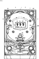
以下、図面を参照しつつ、本発明の一実施形態を詳細に説明する。図1は、本実施の形態におけるパチンコ遊技機の正面図であり、主要部材の配置レイアウトを示す。パチンコ遊技機(遊技機)1は、大別して、遊技盤面を構成する遊技盤(ゲージ盤)2と、遊技盤2を支持固定する遊技機用枠(台枠)3とから構成されている。遊技盤2には、ガイドレールによって囲まれた、ほぼ円形状の遊技領域が形成されている。この遊技領域には、遊技媒体としての遊技球が、所定の打球発射装置から発射されて打ち込まれる。
Hereinafter, an embodiment of the present invention will be described in detail with reference to the drawings. FIG. 1 is a front view of a pachinko gaming machine according to the present embodiment and shows an arrangement layout of main members. The pachinko gaming machine (gaming machine) 1 is roughly composed of a gaming board (gauge board) 2 constituting a gaming board surface and a gaming machine frame (base frame) 3 for supporting and fixing the
遊技盤2の所定位置(図1に示す例では、遊技領域の右側方)には、第1特別図柄表示装置4Aと、第2特別図柄表示装置4Bとが設けられている。第1特別図柄表示装置4Aと第2特別図柄表示装置4Bはそれぞれ、例えば7セグメントやドットマトリクスのLED(発光ダイオード)等から構成され、可変表示ゲームの一例となる特図ゲームにおいて、各々を識別可能な複数種類の識別情報(特別識別情報)である特別図柄(「特図」ともいう)が、変動可能に表示(可変表示)される。例えば、第1特別図柄表示装置4Aと第2特別図柄表示装置4Bはそれぞれ、「0」〜「9」を示す数字や「−」を示す記号等から構成される複数種類の特別図柄を可変表示する。
A first special
なお、第1特別図柄表示装置4Aや第2特別図柄表示装置4Bにおいて表示される特別図柄は、「0」〜「9」を示す数字や「−」を示す記号等から構成されるものに限定されず、例えば7セグメントのLEDにおいて点灯させるものと消灯させるものとの組合せを異ならせた複数種類の点灯パターンが、複数種類の特別図柄として予め設定されていればよい。以下では、第1特別図柄表示装置4Aにおいて可変表示される特別図柄を「第1特図」ともいい、第2特別図柄表示装置4Bにおいて可変表示される特別図柄を「第2特図」ともいう。
The special symbols displayed on the first special
遊技盤2における遊技領域の中央付近には、画像表示装置5が設けられている。画像表示装置5は、例えばLCD(液晶表示装置)等から構成され、各種の演出画像を表示する表示領域を形成している。画像表示装置5の表示領域では、特図ゲームにおける第1特別図柄表示装置4Aによる第1特図の可変表示や第2特別図柄表示装置4Bによる第2特図の可変表示のそれぞれに対応して、例えば3つといった複数の可変表示部となる飾り図柄表示エリアにて、各々を識別可能な複数種類の識別情報(装飾識別情報)である飾り図柄が可変表示される。この飾り図柄の可変表示も、可変表示ゲームに含まれる。
An
一例として、画像表示装置5の表示領域には、「左」、「中」、「右」の飾り図柄表示エリアが配置されている。そして、特図ゲームにおいて第1特別図柄表示装置4Aにおける第1特図の変動と第2特別図柄表示装置4Bにおける第2特図の変動のうち、いずれかが開始されることに対応して、「左」、「中」、「右」の各飾り図柄表示エリアにおいて飾り図柄の変動(例えば上下方向のスクロール表示)が開始される。その後、特図ゲームにおける可変表示結果として確定特別図柄が停止表示されるときに、画像表示装置5における「左」、「中」、「右」の各飾り図柄表示エリアにて、飾り図柄の可変表示結果となる確定飾り図柄(最終停止図柄)が停止表示される。
As an example, “left”, “middle”, and “right” decorative symbol display areas are arranged in the display area of the
このように、画像表示装置5の表示領域では、第1特別図柄表示装置4Aにおける第1特図を用いた特図ゲーム、または、第2特別図柄表示装置4Bにおける第2特図を用いた特図ゲームと同期して、各々が識別可能な複数種類の飾り図柄の可変表示を行い、可変表示結果となる確定飾り図柄を導出表示(あるいは単に「導出」ともいう)する。なお、例えば特別図柄や飾り図柄といった、各種の表示図柄を導出表示するとは、飾り図柄等の識別情報を停止表示(完全停止表示や最終停止表示ともいう)して可変表示を終了させることである。これに対して、飾り図柄の可変表示を開始してから可変表示結果となる確定飾り図柄が導出表示されるまでの可変表示中には、飾り図柄の変動速度が「0」となって、飾り図柄が停留して表示され、例えば微少な揺れや伸縮などを生じさせる表示状態となることがある。このような表示状態は、仮停止表示ともいい、可変表示における表示結果が確定的に表示されていないものの、スクロール表示や更新表示による飾り図柄の変動が進行していないことを遊技者が認識可能となる。なお、仮停止表示には、微少な揺れや伸縮なども生じさせず、所定時間(例えば1秒間)よりも短い時間だけ、飾り図柄を完全停止表示することなどが含まれてもよい。
As described above, in the display area of the
画像表示装置5の画面上には、始動入賞記憶表示エリア5Hが配置されている。始動入賞記憶表示エリア5Hでは、特図ゲームに対応した可変表示の保留数(特図保留記憶数)を特定可能に表示する保留記憶表示が行われる。ここで、特図ゲームに対応した可変表示の保留は、普通入賞球装置6Aが形成する第1始動入賞口や、普通可変入賞球装置6Bが形成する第2始動入賞口を、遊技球が通過(進入)することによる始動入賞に基づいて発生する。すなわち、特図ゲームや飾り図柄の可変表示といった可変表示ゲームを実行するための始動条件(「実行条件」ともいう)は成立したが、先に成立した開始条件に基づく可変表示ゲームが実行中であることやパチンコ遊技機1が大当り遊技状態に制御されていることなどにより、可変表示ゲームの開始を許容する開始条件が成立していないときに、成立した始動条件に対応する可変表示の保留が行われる。
On the screen of the
例えば、第1始動入賞口を遊技球が通過(進入)する第1始動入賞の発生により、第1特別図柄表示装置4Aによる第1特図を用いた特図ゲームの始動条件(第1始動条件)が成立したときに、当該第1始動条件の成立に基づく第1特図を用いた特図ゲームを開始するための第1開始条件が成立しなければ、第1特図保留記憶数が1加算(インクリメント)され、第1特図を用いた特図ゲームの実行が保留される。また、第2始動入賞口を遊技球が通過(進入)する第2始動入賞の発生により、第2特別図柄表示装置4Bによる第2特図を用いた特図ゲームの始動条件(第2始動条件)が成立したときに、当該第2始動条件の成立に基づく第2特図を用いた特図ゲームを開始するための第2開始条件が成立しなければ、第2特図保留記憶数が1加算(インクリメント)され、第2特図を用いた特図ゲームの実行が保留される。これに対して、第1特図を用いた特図ゲームの実行が開始されるときには、第1特図保留記憶数が1減算(デクリメント)され、第2特図を用いた特図ゲームの実行が開始されるときには、第2特図保留記憶数が1減算(デクリメント)される。
For example, a special game start condition (first start condition) using the first special figure by the first special
第1特図保留記憶数と第2特図保留記憶数とを加算した可変表示の保留記憶数は、特に、合計保留記憶数ともいう。単に「特図保留記憶数」というときには、通常、第1特図保留記憶数、第2特図保留記憶数及び合計保留記憶数のいずれも含む概念を指すが、特に、これらの一部(例えば第1特図保留記憶数と第2特図保留記憶数を含む一方で合計保留記憶数は除く概念)を指すこともあるものとする。 The variable display hold memory number obtained by adding the first special figure hold memory number and the second special figure hold memory number is also referred to as a total hold memory number. When simply referring to the “number of special figure hold memory”, it usually refers to a concept including any of the first special figure hold memory number, the second special figure hold memory number, and the total hold memory number. It may refer to a concept that includes the first special figure reserved memory number and the second special figure reserved memory number but excludes the total reserved memory number).
始動入賞記憶表示エリア5Hとともに、あるいは始動入賞記憶表示5Hエリアに代えて、特図保留記憶数を表示する表示器を設けるようにしてもよい。図1に示す例では、始動入賞記憶表示エリア5Hとともに、第1特別図柄表示装置4A及び第2特別図柄表示装置4Bの上部に、特図保留記憶数を特定可能に表示するための第1保留表示器25Aと第2保留表示器25Bとが設けられている。第1保留表示器25Aは、第1特図保留記憶数を特定可能に表示する。第2保留表示器25Bは、第2特図保留記憶数を特定可能に表示する。第1保留表示器25Aと第2保留表示器25Bはそれぞれ、例えば第1特図保留記憶数と第2特図保留記憶数のそれぞれにおける上限値(例えば「4」)に対応した個数(例えば4個)のLEDを含んで構成されている。
A display for displaying the number of reserved special figure memories may be provided together with the start winning
画像表示装置5の下方には、普通入賞球装置6Aと、普通可変入賞球装置6Bとが設けられている。普通入賞球装置6Aは、例えば所定の玉受部材によって常に一定の開放状態に保たれる始動領域(第1始動領域)としての第1始動入賞口を形成する。普通可変入賞球装置6Bは、図2に示す普通電動役物用のソレノイド81によって垂直位置となる閉鎖状態と傾動位置となる開放状態とに変化する一対の可動翼片を有する電動チューリップ型役物(普通電動役物)を備え、第2始動入賞口を形成する。
Below the
一例として、普通可変入賞球装置6Bでは、普通電動役物用のソレノイド81がオフ状態であるときに可動翼片が垂直位置となることにより、遊技球が第2始動入賞口に進入しない閉鎖状態となる。その一方で、普通可変入賞球装置6Bでは、普通電動役物用のソレノイド81がオン状態であるときに可動翼片が傾動位置となることにより、遊技球が第2始動入賞口に進入する開放状態(第1状態)となる。なお、普通可変入賞球装置6Bは、閉鎖状態(第2状態)であるときでも、第2始動入賞口には遊技球が進入可能であるものの、開放状態であるときよりも遊技球が進入する可能性が低くなるように構成してもよい。このように、遊技領域には、遊技球が進入可能な開放状態(第1状態)と、遊技球が進入不可能または進入困難な閉鎖状態(第2状態)とに変化する第2始動入賞口を形成する普通可変入賞球装置6Bが設けられている。 As an example, in the ordinary variable winning ball apparatus 6B, the movable wing piece is in the vertical position when the solenoid 81 for the ordinary electric accessory is in the off state, so that the game ball does not enter the second start winning opening. It becomes. On the other hand, in the ordinary variable winning ball apparatus 6B, the movable wing piece is in the tilting position when the solenoid 81 for the ordinary electric accessory is in the on state, so that the game ball enters the second start winning opening. State (first state). In the normal variable winning ball apparatus 6B, although the game ball can enter the second start winning opening even in the closed state (second state), the game ball enters more than in the open state. You may comprise so that possibility may become low. Thus, in the game area, the second starting prize opening that changes between an open state (first state) in which a game ball can enter and a closed state (second state) in which the game ball cannot enter or is difficult to enter. Is provided with an ordinary variable winning ball apparatus 6B.
普通入賞球装置6Aに形成された第1始動入賞口に進入した遊技球は、例えば図2に示す第1始動口スイッチ22Aによって検出される。普通可変入賞球装置6Bに形成された第2始動入賞口に進入した遊技球は、例えば図2に示す第2始動口スイッチ22Bによって検出される。第1始動口スイッチ22Aによって遊技球が検出されたことに基づき、所定個数(例えば3個)の遊技球が賞球(景品遊技媒体)として払い出され、第1保留記憶数が所定の上限値(例えば「4」)以下であれば、第1始動条件が成立する。第2始動口スイッチ22Bによって遊技球が検出されたことに基づき、所定個数(例えば3個)の遊技球が賞球として払い出され、第2保留記憶数が所定の上限値以下であれば、第2始動条件が成立する。
A game ball that has entered the first start winning opening formed in the normal
なお、第1始動口スイッチ22Aによって遊技球が検出されたことに基づいて払い出される賞球の個数と、第2始動口スイッチ22Bによって遊技球が検出されたことに基づいて払い出される賞球の個数は、互いに同一の個数であってもよいし、異なる個数であってもよい。パチンコ遊技機1は、賞球となる遊技球を直接に払い出すものであってもよいし、賞球となる遊技球の個数に対応した得点を付与するものであってもよい。
The number of prize balls to be paid out based on the detection of the game ball by the first
普通入賞球装置6Aと普通可変入賞球装置6Bの下方には、特別可変入賞球装置7が設けられている。特別可変入賞球装置7は、図2に示す大入賞口扉用となるソレノイド82によって開閉駆動される大入賞口扉を備え、その大入賞口扉によって開放状態と閉鎖状態とに変化する特定領域としての大入賞口を形成する。
A special variable winning
一例として、特別可変入賞球装置7では、大入賞口扉用のソレノイド82がオフ状態であるときに大入賞口扉が大入賞口を閉鎖状態として、遊技球が大入賞口を通過(進入)できなくする。その一方で、特別可変入賞球装置7では、大入賞口扉用のソレノイド82がオン状態であるときに大入賞口扉が大入賞口を開放状態として、遊技球が大入賞口を通過(進入)しやすくする。このように、特定領域としての大入賞口は、遊技球が通過(進入)しやすく遊技者にとって有利な開放状態と、遊技球が通過(進入)できず遊技者にとって不利な閉鎖状態とに変化する。なお、遊技球が大入賞口を通過(進入)できない閉鎖状態に代えて、あるいは閉鎖状態の他に、遊技球が大入賞口を通過(進入)しにくい一部開放状態を設けてもよい。
As an example, in the special variable winning
大入賞口を通過(進入)した遊技球は、例えば図2に示すカウントスイッチ23によって検出される。カウントスイッチ23によって遊技球が検出されたことに基づき、所定個数(例えば14個)の遊技球が賞球として払い出される。こうして、特別可変入賞球装置7において開放状態となった大入賞口を遊技球が通過(進入)したときには、例えば第1始動入賞口や第2始動入賞口といった、他の入賞口を遊技球が通過(進入)したときよりも多くの賞球が払い出される。したがって、特別可変入賞球装置7において大入賞口が開放状態となれば、その大入賞口に遊技球が進入可能となり、遊技者にとって有利な第1状態となる。その一方で、特別可変入賞球装置7において大入賞口が閉鎖状態または一部閉鎖状態となれば、大入賞口に遊技球を通過(進入)させて賞球を得ることが不可能または困難になり、遊技者にとって不利な第2状態となる。
The game ball that has passed (entered) through the big prize opening is detected by, for example, the count switch 23 shown in FIG. Based on the detection of game balls by the count switch 23, a predetermined number (for example, 14) of game balls are paid out as prize balls. In this way, when the game ball passes (enters) through the large winning opening opened in the special variable winning
遊技盤2の所定位置(図1に示す例では、遊技領域の左側方)には、普通図柄表示器20が設けられている。一例として、普通図柄表示器20は、第1特別図柄表示装置4Aや第2特別図柄表示装置4Bと同様に7セグメントやドットマトリクスのLED等から構成され、特別図柄とは異なる複数種類の識別情報である普通図柄(「普図」あるいは「普通図」ともいう)を変動可能に表示(可変表示)する。このような普通図柄の可変表示は、普図ゲーム(「普通図ゲーム」ともいう)と称される。普通図柄表示器20の上方には、普図保留表示器25Cが設けられている。普図保留表示器25Cは、例えば4個のLEDを含んで構成され、通過ゲート41を通過した有効通過球数としての普図保留記憶数を表示する。
A
遊技盤2の表面には、上記の構成以外にも、遊技球の流下方向や速度を変化させる風車及び多数の障害釘が設けられている。また、第1始動入賞口、第2始動入賞口及び大入賞口とは異なる入賞口として、例えば所定の玉受部材によって常に一定の開放状態に保たれる単一または複数の一般入賞口が設けられてもよい。この場合には、一般入賞口のいずれかに進入した遊技球が所定の一般入賞球スイッチによって検出されたことに基づき、所定個数(例えば10個)の遊技球が賞球として払い出されればよい。遊技領域の最下方には、いずれの入賞口にも進入しなかった遊技球が取り込まれるアウト口が設けられている。
In addition to the above-described configuration, the surface of the
遊技機用枠3の左右上部位置には、効果音等を再生出力するためのスピーカ8L、8Rが設けられており、さらに遊技領域周辺部には、遊技効果ランプ9が設けられている。パチンコ遊技機1の遊技領域における各構造物(例えば普通入賞球装置6A、普通可変入賞球装置6B、特別可変入賞球装置7等)の周囲には、装飾用LEDが配置されていてもよい。遊技機用枠3の右下部位置には、遊技媒体としての遊技球を遊技領域に向けて発射するために遊技者等によって操作される打球操作ハンドル(操作ノブ)が設けられている。例えば、打球操作ハンドルは、遊技者等による操作量(回転量)に応じて遊技球の弾発力を調整する。
遊技領域の下方における遊技機用枠3の所定位置には、賞球として払い出された遊技球や所定の球貸機により貸し出された遊技球を、打球発射装置へと供給可能に保持(貯留)する上皿(打球供給皿)が設けられている。遊技機用枠3の下部には、上皿から溢れた余剰球などを、パチンコ遊技機1の外部へと排出可能に保持(貯留)する下皿が設けられている。
At a predetermined position of the
下皿を形成する部材には、例えば下皿本体の上面における手前側の所定位置(例えば下皿の中央部分)などに、遊技者が把持して傾倒操作が可能なスティックコントローラ31Aが取り付けられている。スティックコントローラ31Aは、遊技者が把持する操作桿を含み、操作桿の所定位置(例えば遊技者が操作桿を把持したときに操作手の人差し指が掛かる位置など)には、トリガボタンが設けられている。トリガボタンは、遊技者がスティックコントローラ31Aの操作桿を操作手(例えば左手など)で把持した状態において、所定の操作指(例えば人差し指など)で押引操作することなどにより所定の指示操作ができるように構成されていればよい。操作桿の内部には、トリガボタンに対する押引操作などによる所定の指示操作を検知するトリガセンサが内蔵されていればよい。
For example, a
スティックコントローラ31Aの下部における下皿の本体内部などには、操作桿に対する傾倒操作を検知する傾倒方向センサユニットを含むコントローラセンサユニット35Aが設けられていればよい。例えば、傾倒方向センサユニットは、パチンコ遊技機1と正対する遊技者の側からみて操作桿の中心位置よりも左側で遊技盤2の盤面と平行に配置された2つの透過形フォトセンサ(平行センサ対)と、この遊技者の側からみて操作桿の中心位置よりも右側で遊技盤2の盤面と垂直に配置された2つの透過形フォトセンサ(垂直センサ対)とを組み合わせた4つの透過形フォトセンサを含んで構成されていればよい。
A
上皿を形成する部材には、例えば上皿本体の上面における手前側の所定位置(例えばスティックコントローラ31Aの上方)などに、遊技者が押下操作などにより所定の指示操作を可能なプッシュボタン31Bが設けられている。プッシュボタン31Bは、遊技者からの押下操作などによる所定の指示操作を、機械的、電気的、あるいは、電磁的に、検出できるように構成されていればよい。プッシュボタン31Bの設置位置における上皿の本体内部などには、プッシュボタン31Bに対してなされた遊技者の操作行為を検知するプッシュセンサ35Bが設けられていればよい。
The member that forms the upper plate includes, for example, a
パチンコ遊技機1には、例えば図2に示すような主基板11、演出制御基板12、音声制御基板13、ランプ制御基板14といった、各種の制御基板が搭載されている。また、パチンコ遊技機1には、主基板11と演出制御基板12との間で伝送される各種の制御信号を中継するための中継基板15なども搭載されている。その他にも、パチンコ遊技機1における遊技盤などの背面には、例えば払出制御基板、情報端子基板、発射制御基板、インタフェース基板、タッチセンサ基板などといった、各種の基板が配置されている。
Various control boards such as a
主基板11は、メイン側の制御基板であり、パチンコ遊技機1における遊技の進行を制御するための各種回路が搭載されている。主基板11は、主として、特図ゲームにおいて用いる乱数の設定機能、所定位置に配設されたスイッチ等からの信号の入力を行う機能、演出制御基板12などからなるサブ側の制御基板に宛てて、指令情報の一例となる制御コマンドを制御信号として出力して送信する機能、ホールの管理コンピュータに対して各種情報を出力する機能などを備えている。また、主基板11は、第1特別図柄表示装置4Aと第2特別図柄表示装置4Bを構成する各LED(例えばセグメントLED)などの点灯/消灯制御を行って第1特図や第2特図の可変表示を制御することや、普通図柄表示器20の点灯/消灯/発色制御などを行って普通図柄表示器20による普通図柄の可変表示を制御することといった、所定の表示図柄の可変表示を制御する機能も備えている。
The
主基板11には、例えば遊技制御用マイクロコンピュータ100やスイッチ回路110、ソレノイド回路111などが搭載されている。スイッチ回路110は、遊技球検出用の各種スイッチからの検出信号を取り込んで遊技制御用マイクロコンピュータ100に伝送する。ソレノイド回路111は、遊技制御用マイクロコンピュータ100からのソレノイド駆動信号を、普通電動役物用のソレノイド81や大入賞口扉用のソレノイド82に伝送する。
On the
演出制御基板12は、主基板11とは独立したサブ側の制御基板であり、中継基板15を介して主基板11から伝送された制御信号を受信して、画像表示装置5、スピーカ8L、8R及び遊技効果ランプ9や装飾用LEDといった演出用の電気部品による演出動作を制御するための各種回路が搭載されている。すなわち、演出制御基板12は、画像表示装置5における表示動作や、スピーカ8L、8Rからの音声出力動作の全部または一部、遊技効果ランプ9や装飾用LEDなどにおける点灯/消灯動作の全部または一部といった、演出用の電気部品に所定の演出動作を実行させるための制御内容を決定する機能を備えている。
The
音声制御基板13は、演出制御基板12とは別個に設けられた音声出力制御用の制御基板であり、演出制御基板12からの指令や制御データなどに基づき、スピーカ8L、8Rから音声を出力させるための音声信号処理を実行する処理回路などが搭載されている。ランプ制御基板14は、演出制御基板12とは別個に設けられたランプ出力制御用の制御基板であり、演出制御基板12からの指令や制御データなどに基づき、遊技効果ランプ9や装飾用LEDなどにおける点灯/消灯駆動を行うランプドライバ回路などが搭載されている。
The
図2に示すように、主基板11には、ゲートスイッチ21、始動口スイッチ(第1始動口スイッチ22Aおよび第2始動口スイッチ22B)、カウントスイッチ23といった、各種スイッチからの検出信号を伝送する配線が接続されている。なお、各種スイッチは、例えばセンサと称されるものなどのように、遊技媒体としての遊技球を検出できる任意の構成を有するものであればよい。また、主基板11には、第1特別図柄表示装置4A、第2特別図柄表示装置4B、普通図柄表示器20などの表示制御を行うための指令信号を伝送する配線が接続されている。
As shown in FIG. 2, detection signals from various switches such as a
主基板11から演出制御基板12に向けて伝送される制御信号は、中継基板15によって中継される。中継基板15を介して主基板11から演出制御基板12に対して伝送される制御コマンドは、例えば電気信号として送受信される演出制御コマンドである。演出制御コマンドには、例えば画像表示装置5における画像表示動作を制御するために用いられる表示制御コマンドや、スピーカ8L、8Rからの音声出力を制御するために用いられる音声制御コマンド、遊技効果ランプ9や装飾用LEDの点灯動作などを制御するために用いられるランプ制御コマンドが含まれている。これらの演出制御コマンドはいずれも、例えば2バイト構成であり、1バイト目はMODE(コマンドの分類)を示し、2バイト目はEXT(コマンドの種類)を表す。MODEデータの先頭ビット(ビット7)は必ず「1」となり、EXTデータの先頭ビットは「0」となるように、予め設定されていればよい。
A control signal transmitted from the
主基板11に搭載された遊技制御用マイクロコンピュータ100は、例えば1チップのマイクロコンピュータであり、遊技制御用のプログラムや固定データ等を記憶するROM(Read Only Memory)101と、遊技制御用のワークエリアを提供するRAM(Random Access Memory)102と、遊技制御用のプログラムを実行して制御動作を行うCPU(Central Processing Unit)103と、CPU103とは独立して乱数値を示す数値データの更新を行う乱数回路104と、I/O(Input/Output port)105とを備えて構成される。
The
一例として、遊技制御用マイクロコンピュータ100では、CPU103がROM101から読み出したプログラムを実行することにより、パチンコ遊技機1における遊技の進行を制御するための処理が実行される。このときには、CPU103がROM101から固定データを読み出す固定データ読出動作や、CPU103がRAM102に各種の変動データを書き込んで一時記憶させる変動データ書込動作、CPU103がRAM102に一時記憶されている各種の変動データを読み出す変動データ読出動作、CPU103がI/O105を介して遊技制御用マイクロコンピュータ100の外部から各種信号の入力を受け付ける受信動作、CPU103がI/O105を介して遊技制御用マイクロコンピュータ100の外部へと各種信号を出力する送信動作なども行われる。
As an example, in the
なお、遊技制御用マイクロコンピュータ100を構成する1チップのマイクロコンピュータは、少なくともCPU103の他にRAM102が内蔵されていればよく、ROM101や乱数回路104、I/O105などは外付けされてもよい。
Note that the one-chip microcomputer constituting the
遊技制御用マイクロコンピュータ100では、例えば乱数回路104などにより、遊技の進行を制御するために用いられる各種の乱数値を示す数値データが更新可能にカウントされる。遊技の進行を制御するために用いられる乱数は、遊技用乱数ともいう。遊技用乱数は、乱数回路104などのハードウェアによって更新されるものであってもよいし、遊技制御用マイクロコンピュータ100のCPU103が所定のコンピュータプログラムを実行することでソフトウェアによって更新されるものであってもよい。例えば、遊技制御用マイクロコンピュータ100におけるRAM102の所定領域(遊技制御カウンタ設定部など)に設けられたランダムカウンタや、RAM102とは別個の内部レジスタに設けられたランダムカウンタに、所定の乱数値を示す数値データを格納し、CPU103が定期的または不定期的に格納値を更新することで、乱数値の更新が行われるようにしてもよい。
In the
遊技制御用マイクロコンピュータ100が備えるROM101には、ゲーム制御用のプログラムの他にも、遊技の進行を制御するために用いられる各種の選択用データ、テーブルデータなどが格納されている。例えば、ROM101には、CPU103が各種の判定や決定、設定を行うために用意された複数の判定テーブルや決定テーブル、設定テーブルなどを構成するデータが記憶されている。また、ROM101には、CPU103が主基板11から各種の制御コマンドとなる制御信号を送信するために用いられる複数のコマンドテーブルを構成するテーブルデータや、変動パターンを複数種類格納する変動パターンテーブルを構成するテーブルデータなどが、記憶されている。遊技制御用マイクロコンピュータ100が備えるRAM102には、パチンコ遊技機1における遊技の進行などを制御するために用いられる各種データが書換可能に一時記憶される。
In addition to the game control program, the
演出制御基板12には、プログラムに従って制御動作を行う演出制御用CPU120と、演出制御用のプログラムや固定データ等を記憶するROM121と、演出制御用CPU120のワークエリアを提供するRAM122と、画像表示装置5における表示動作の制御内容を決定するための処理などを実行する表示制御部123と、演出制御用CPU120とは独立して乱数値を示す数値データの更新を行う乱数回路124と、I/O125とが搭載されている。
The
一例として、演出制御基板12では、演出制御用CPU120がROM121から読み出した演出制御用のプログラムを実行することにより、演出用の電気部品による演出動作を制御するための処理が実行される。このときには、演出制御用CPU120がROM121から固定データを読み出す固定データ読出動作や、演出制御用CPU120がRAM122に各種の変動データを書き込んで一時記憶させる変動データ書込動作、演出制御用CPU120がRAM122に一時記憶されている各種の変動データを読み出す変動データ読出動作、演出制御用CPU120がI/O125を介して演出制御基板12の外部から各種信号の入力を受け付ける受信動作、演出制御用CPU120がI/O125を介して演出制御基板12の外部へと各種信号を出力する送信動作なども行われる。
As an example, in the
演出制御用CPU120、ROM121、RAM122は、演出制御基板12に搭載された1チップの演出制御用マイクロコンピュータに含まれてもよい。演出制御基板12には、画像表示装置5に対して映像信号を伝送するための配線や、音声制御基板13に対して音番号データを示す情報信号としての効果音信号を伝送するための配線、ランプ制御基板14に対してランプデータを示す情報信号としての電飾信号を伝送するための配線などが接続されている。さらに、演出制御基板12には、スティックコントローラ31Aに対する遊技者の操作行為を検出したことを示す情報信号としての操作検出信号を、コントローラセンサユニット35Aから伝送するための配線や、プッシュボタン31Bに対する遊技者の操作行為を検出したことを示す情報信号としての操作検出信号を、プッシュセンサ35Bから伝送するための配線も接続されている。
The
演出制御基板12では、例えば乱数回路124などにより、演出動作を制御するために用いられる各種の乱数値を示す数値データが更新可能にカウントされる。こうした演出動作を制御するために用いられる乱数は、演出用乱数ともいう。
On the
図2に示す演出制御基板12に搭載されたROM121には、演出制御用のプログラムの他にも、演出動作を制御するために用いられる各種のデータテーブルなどが格納されている。例えば、ROM121には、演出制御用CPU120が各種の判定や決定、設定を行うために用意された複数の判定テーブルや決定テーブルを構成するテーブルデータ、各種の演出制御パターンを構成するパターンデータなどが記憶されている。演出制御基板12に搭載されたRAM122には、演出動作を制御するために用いられる各種データが記憶される。
In addition to the effect control program, the
演出制御基板12に搭載された表示制御部123は、演出制御用CPU120からの表示制御指令などに基づき、画像表示装置5における表示動作の制御内容を決定する。例えば、表示制御部123は、画像表示装置5の表示領域内に表示させる演出画像の切換タイミングを決定することなどにより、飾り図柄の可変表示や各種の演出表示を実行させるための制御を行う。一例として、表示制御部123には、VDP(Video Display Processor)、CGROM(Character Generator ROM)、VRAM(Video RAM)、LCD駆動回路などが搭載されていればよい。なお、VDPは、GPU(Graphics Processing Unit)、GCL(Graphics Controller LSI)、あるいは、より一般的にDSP(Digital Signal Processor)と称される画像処理用のマイクロプロセッサであってもよい。CGROMは、例えば書換不能な半導体メモリであってもよいし、フラッシュメモリなどの書換可能な半導体メモリであってもよく、あるいは、磁気メモリ、光学メモリといった、不揮発性記録媒体のいずれかを用いて構成されたものであればよい。
The
演出制御基板12に搭載されたI/O125は、例えば主基板11などから伝送された演出制御コマンドを取り込むための入力ポートと、演出制御基板12の外部へと各種信号を伝送するための出力ポートとを含んで構成される。例えば、I/O125の出力ポートからは、画像表示装置5へと伝送される映像信号や、音声制御基板13へと伝送される指令(効果音信号)、ランプ制御基板14へと伝送される指令(電飾信号)などが出力される。
The I /
パチンコ遊技機1においては、遊技媒体としての遊技球を用いた所定の遊技が行われ、その遊技結果に基づいて所定の遊技価値が付与可能となる。遊技球を用いた遊技の一例として、パチンコ遊技機1における筐体前面の右下方に設置された打球操作ハンドルが遊技者によって所定操作(例えば回転操作)されたことに基づいて、所定の打球発射装置が備える発射モータなどにより、遊技媒体としての遊技球が遊技領域に向けて発射される。遊技領域を流下した遊技球が、普通入賞球装置6Aに形成された第1始動入賞口(第1始動領域)を通過(進入)すると、図2に示す第1始動口スイッチ22Aによって遊技球が検出されたことなどにより第1始動条件が成立する。その後、例えば前回の特図ゲームや大当り遊技状態が終了したことなどにより第1開始条件が成立したことに基づいて、第1特別図柄表示装置4Aによる第1特図を用いた特図ゲームが開始される。
In the
また、遊技球が普通可変入賞球装置6Bに形成された第2始動入賞口(第2始動領域)を通過(進入)すると、図2に示す第2始動口スイッチ22Bによって遊技球が検出されたことなどにより第2始動条件が成立する。その後、例えば前回の特図ゲームや大当り遊技状態が終了したことなどにより第2開始条件が成立したことに基づいて、第2特別図柄表示装置4Bによる第2特図を用いた特図ゲームが開始される。ただし、普通可変入賞球装置6Bが第2状態としての閉鎖状態であるときには、第2始動入賞口を遊技球が通過困難または通過不可能である。
Further, when the game ball passes (enters) the second start winning opening (second start area) formed in the normal variable winning ball apparatus 6B, the game ball is detected by the second
通過ゲート41を通過した遊技球が図2に示すゲートスイッチ21によって検出されたことに基づいて、普通図柄表示器20にて普通図柄の可変表示を実行するための普図始動条件が成立する。その後、例えば前回の普図ゲームが終了したことといった、普通図柄の可変表示を開始するための普図開始条件が成立したことに基づいて、普通図柄表示器20による普図ゲームが開始される。この普図ゲームでは、普通図柄の変動を開始させた後、所定時間が経過すると、普通図柄の可変表示結果となる確定普通図柄を停止表示(導出表示)する。このとき、確定普通図柄として特定の普通図柄(普図当り図柄)が停止表示されれば、普通図柄の可変表示結果が「普図当り」となる。その一方、確定普通図柄として普図当り図柄以外の普通図柄が停止表示されれば、普通図柄の可変表示結果が「普図ハズレ」となる。普通図柄の可変表示結果が「普図当り」となったことに対応して、普通可変入賞球装置6Bを構成する電動チューリップの可動翼片が傾動位置となる開放制御が行われ、所定時間が経過すると垂直位置に戻る閉鎖制御が行われる。
Based on the fact that the game ball that has passed through the
第1特別図柄表示装置4Aによる第1特図を用いた特図ゲームが開始されるときや、第2特別図柄表示装置4Bによる第2特図を用いた特図ゲームが開始されるときには、特別図柄の可変表示結果を予め定められた特定表示結果としての「大当り」にするか否かが、その可変表示結果を導出表示する以前に決定(事前決定)される。そして、可変表示結果の決定に基づく所定割合で、変動パターンの決定などが行われ、可変表示結果や変動パターンを指定する演出制御コマンドが、図2に示す主基板11の遊技制御用マイクロコンピュータ100から演出制御基板12に向けて伝送される。
When a special symbol game using the first special symbol by the first special
こうした可変表示結果や変動パターンの決定に基づいて特図ゲームが開始された後、例えば変動パターンに対応して予め定められた可変表示時間が経過したときには、可変表示結果となる確定特別図柄が導出表示される。第1特別図柄表示装置4Aや第2特別図柄表示装置4Bによる特別図柄の可変表示に対応して、画像表示装置5の表示領域に配置された「左」、「中」、「右」の飾り図柄表示エリア5L、5C、5Rでは、特別図柄とは異なる飾り図柄(演出図柄)の可変表示が行われる。
After the special figure game is started based on the determination of the variable display result and the variation pattern, for example, when a predetermined variable display time corresponding to the variation pattern elapses, a definite special symbol as a variable display result is derived. Is displayed. Corresponding to the variable display of special symbols by the first special
第1特別図柄表示装置4Aによる第1特図を用いた特図ゲームや、第2特別図柄表示装置4Bによる第2特図を用いた特図ゲームにおいて、特別図柄の可変表示結果となる確定特別図柄が導出表示されるときには、画像表示装置5において飾り図柄の可変表示結果となる確定飾り図柄が導出表示される。特別図柄の可変表示結果として予め定められた大当り図柄が導出表示されたときには、可変表示結果(特図表示結果)が「大当り」(特定表示結果)となり、遊技者にとって有利な特定遊技状態としての大当り遊技状態に制御される。特別図柄の可変表示結果として、大当り図柄が導出表示されず、ハズレ図柄が導出表示されたときには、可変表示結果(特図表示結果)が「ハズレ」となる。
In the special symbol game using the first special symbol by the first special
一例として、「3」や「7」の数字を示す特別図柄を大当り図柄とし、「−」の記号を示す特別図柄をハズレ図柄とする。なお、第1特別図柄表示装置4Aによる特図ゲームにおける大当り図柄やハズレ図柄といった各図柄は、第2特別図柄表示装置4Bによる特図ゲームにおける各図柄とは異なる特別図柄となるようにしてもよいし、双方の特図ゲームにおいて共通の特別図柄が大当り図柄やハズレ図柄となるようにしてもよい。また、数字や記号として特定の意味を有する点灯パターンの特別図柄を大当り図柄やハズレ図柄とするものに限定されず、例えば7セグメントのLEDにおける任意の点灯パターンの特別図柄を、大当り図柄やハズレ図柄としてもよい。
As an example, a special symbol indicating the numbers “3” and “7” is a jackpot symbol, and a special symbol indicating the symbol “−” is a lose symbol. Each symbol such as a jackpot symbol or a lost symbol in the special symbol game by the first special
大当り遊技状態では、大入賞口が開放状態となって特別可変入賞球装置7が遊技者にとって有利な第1状態となる。そして、所定期間(例えば29秒間)あるいは所定個数(例えば9個)の遊技球が大入賞口に進入して入賞球が発生するまでの期間にて、大入賞口を継続して開放状態とするラウンド遊技が実行される。こうしたラウンド遊技の実行期間以外の期間では、大入賞口が閉鎖状態となり、入賞球が発生困難または発生不可能となる。大入賞口に遊技球が進入したときには、カウントスイッチ23により入賞球が検出され、その検出ごとに所定個数(例えば14個)の遊技球が賞球として払い出される。大当り遊技状態におけるラウンド遊技は、所定の上限回数(例えば「15」)に達するまで繰り返し実行される。
In the big hit gaming state, the special winning opening is in an open state, and the special variable winning
特図表示結果が「大当り」となる場合には、大当り種別が「非確変」または「確変」のいずれかとなる場合が含まれている。例えば、特別図柄の可変表示結果として、「3」の数字を示す大当り図柄が導出表示されたときには大当り種別が「非確変」となり、「7」の数字を示す大当り図柄が導出表示されたときには大当り種別が「確変」となる。大当り種別が「非確変」または「確変」となった場合には、大当り遊技状態におけるラウンド遊技として、特別可変入賞球装置7を遊技者にとって有利な第1状態(大入賞口を開放状態)とする上限時間が比較的に長い時間(例えば29秒など)となる通常開放ラウンドが実行される。なお、大当り遊技状態におけるラウンド遊技として、特別可変入賞球装置7を第1状態(大入賞口を開放状態)とする上限時間が比較的に短い時間(例えば0.1秒など)となる短期開放ラウンドが実行される大当り種別(例えば「突確」など)を設けてもよい。
When the special figure display result is “big hit”, the case where the big hit type is “non-probable change” or “probable change” is included. For example, as a result of variable display of a special symbol, when the big hit symbol indicating the number “3” is derived and displayed, the big hit type is “non-probable change”, and when the big hit symbol indicating the number “7” is derived and displayed, The type is “probable change”. When the jackpot type is “non-probability change” or “probability change”, as a round game in the big hit gaming state, the special variable winning
大当り遊技状態が終了した後には、所定の確変制御条件が成立したことに基づいて、可変表示結果が「大当り」となる確率(大当り確率)が通常状態よりも高くなる確変状態に制御されることがある。確変状態は、所定回数の可変表示が実行されること、あるいは次回の大当り遊技状態が開始されることといった、所定の確変終了条件が成立するまで、継続するように制御される。また、大当り遊技状態が終了した後には、平均的な可変表示時間が通常状態よりも短くなる時短状態に制御されることがある。時短状態は、所定回数の可変表示が実行されたことと、次回の大当り遊技状態が開始されたことのうち、いずれか一方の時短終了条件が先に成立するまで、継続するように制御される。一例として、大当り種別が「非確変」である場合に大当り遊技状態が終了した後には、遊技状態が時短状態となる。一方、大当り種別が「確変」である場合に大当り遊技状態が終了した後には、遊技状態が確変状態となる。 After the big hit gaming state is finished, the probability that the variable display result will be “big hit” (hit probability) is controlled to be a positive change state that is higher than the normal state based on the fact that the predetermined probability change control condition is satisfied. There is. The probability change state is controlled so as to continue until a predetermined probability change end condition such as a predetermined number of variable displays is executed or the next big hit gaming state is started. In addition, after the big hit gaming state is ended, the average variable display time may be controlled to a short state when it becomes shorter than the normal state. The short-time state is controlled to continue until one of the short-time end conditions is established first, among the fact that a predetermined number of variable displays have been executed and the next big hit gaming state has been started. . As an example, when the big hit type is “non-probable change”, after the big hit gaming state is ended, the gaming state becomes a short-time state. On the other hand, when the big hit type is “probability change”, after the big hit game state is ended, the game state becomes the probability change state.
確変状態や時短状態では、通常状態よりも第2始動入賞口を遊技球が通過(進入)しやすい有利変化態様で、普通可変入賞球装置6Bを第1状態(開放状態)と第2状態(閉鎖状態)とに変化させる。例えば、普通図柄表示器20による普図ゲームにおける普通図柄の変動時間(普図変動時間)を通常状態のときよりも短くする制御や、各回の普図ゲームで普通図柄の可変表示結果が「普図当り」となる確率を通常状態のときよりも向上させる制御、可変表示結果が「普図当り」となったことに基づく普通可変入賞球装置6Bにおける可動翼片の傾動制御を行う傾動制御時間を通常状態のときよりも長くする制御、その傾動回数を通常状態のときよりも増加させる制御により、普通可変入賞球装置6Bを有利変化態様で第1状態と第2状態とに変化させればよい。なお、これらの制御のいずれか1つが行われるようにしてもよいし、複数の制御が組み合わせられて行われるようにしてもよい。このように、普通可変入賞球装置6Bを有利変化態様で第1状態と第2状態とに変化させる制御は、高開放制御(「高ベース制御」ともいう)と称される。こうした確変状態や時短状態に制御されることにより、次に可変表示結果が「大当り」となるまでの所要時間が短縮され、通常状態よりも遊技者にとって有利な特別遊技状態となる。
In the probability change state and the short time state, the normally variable winning ball apparatus 6B is in the first state (open state) and the second state (in an advantageous change mode in which the game ball easily passes (enters) through the second start winning opening than the normal state. Closed). For example, the normal
パチンコ遊技機1において遊技媒体として用いられる遊技球や、その個数に対応して付与される得点の記録情報は、例えば数量に応じて特殊景品や一般景品に交換可能な有価価値を有するものであればよい。あるいは、これらの遊技球や得点の記録情報は、特殊景品や一般景品には交換できないものの、パチンコ遊技機1で再度の遊技に使用可能な有価価値を有するものであってもよい。
The game ball used as a game medium in the
画像表示装置5に設けられた「左」、「中」、「右」の飾り図柄表示エリア5L、5C、5Rでは、第1特別図柄表示装置4Aにおける第1特図を用いた特図ゲームと、第2特別図柄表示装置4Bにおける第2特図を用いた特図ゲームとのうち、いずれかの特図ゲームが開始されることに対応して、飾り図柄の可変表示が開始される。そして、飾り図柄の可変表示が開始されてから「左」、「中」、「右」の各飾り図柄表示エリア5L、5C、5Rにおける確定飾り図柄の停止表示により可変表示が終了するまでの期間では、飾り図柄の可変表示態様が所定のリーチ態様(リーチ状態)となることがある。
In the “left”, “middle”, and “right” decorative
ここで、リーチ態様とは、画像表示装置5の表示領域にて停止表示された飾り図柄が大当り組合せの一部を構成しているときに未だ停止表示されていない飾り図柄(「リーチ変動図柄」ともいう)については変動が継続している表示態様、あるいは、全部または一部の飾り図柄が大当り組合せの全部または一部を構成しながら同期して変動している表示態様のことである。具体的には、「左」、「中」、「右」の飾り図柄表示エリア5L、5C、5Rにおける一部(例えば「左」及び「右」の飾り図柄表示エリア5L、5Rなど)では予め定められた大当り組合せを構成する飾り図柄(例えば「7」の英数字を示す飾り図柄)が停止表示されているときに未だ停止表示していない残りの飾り図柄表示エリア(例えば「中」の飾り図柄表示エリア5Cなど)では飾り図柄が変動している表示態様、あるいは、「左」、「中」、「右」の飾り図柄表示エリア5L、5C、5Rにおける全部または一部で飾り図柄が大当り組合せの全部または一部を構成しながら同期して変動している表示態様である。
Here, the reach mode refers to a decorative pattern that has not yet been stopped when the decorative symbol that is stopped and displayed in the display area of the
また、リーチ態様となったことに対応して、飾り図柄の変動速度を低下させたり、画像表示装置5の表示領域に飾り図柄とは異なるキャラクタ画像(人物等を模した演出画像)を表示させたり、背景画像の表示態様を変化させたり、飾り図柄とは異なる動画像を再生表示させたり、飾り図柄の可変表示態様を変化させたりすることで、リーチ態様となる以前とは異なる演出動作が実行される場合がある。このようなキャラクタ画像の表示や背景画像の表示態様の変化、動画像の再生表示、飾り図柄の可変表示態様の変化といった演出動作を、リーチ演出表示(あるいは単にリーチ演出)という。なお、リーチ演出には、画像表示装置5における表示動作のみならず、スピーカ8L、8Rによる音声出力動作や、遊技効果ランプ9などの発光体における点灯動作(点滅動作)などを、リーチ態様となる以前の動作態様とは異なる動作態様とすることが、含まれていてもよい。
Further, in response to the reach mode, the decorative pattern variation speed is reduced, or a character image (an effect image simulating a person) different from the decorative pattern is displayed in the display area of the
リーチ演出における演出動作としては、互いに動作態様(演出態様)が異なる複数種類の演出パターン(「リーチパターン」ともいう)が、予め用意されていればよい。そして、それぞれのリーチ演出における演出態様に応じて、「大当り」となる可能性(「期待度」あるいは「大当り期待度」ともいう)が異なる。すなわち、複数種類のリーチ演出のいずれが実行されるかに応じて、可変表示結果が「大当り」となる可能性を異ならせることができる。この実施の形態では、一例として、ノーマル(ノーマルリーチ)、スーパーA(スーパーリーチA)、スーパーB(スーパーリーチB)、スーパーC(スーパーリーチC)といったリーチ演出が予め設定されている。そして、スーパーAやスーパーB、スーパーCといったスーパーリーチのリーチ演出が実行された場合には、ノーマルのリーチ演出が実行された場合に比べて、可変表示結果が「大当り」となる可能性(大当り期待度)が高くなる。また、スーパーリーチのリーチ演出のうちでも、スーパーCのリーチ演出が実行された場合には、スーパーBのリーチ演出が実行された場合に比べて、大当り期待度が高くなり、スーパーBのリーチ演出が実行された場合には、スーパーAのリーチ演出が実行された場合に比べて、大当り期待度が高くなる。 As an effect operation in the reach effect, a plurality of types of effect patterns (also referred to as “reach patterns”) having different operation modes (effect modes) may be prepared in advance. Then, the possibility of being a “hit” (also referred to as “expectation degree” or “hit expectation degree”) varies depending on the production mode in each reach production. That is, it is possible to vary the possibility that the variable display result will be a “hit” depending on which of the multiple types of reach effects is executed. In this embodiment, as an example, reach effects such as normal (normal reach), super A (super reach A), super B (super reach B), and super C (super reach C) are preset. And, when the reach production of super reach such as Super A, Super B, and Super C is executed, the variable display result may be a “big hit” compared to the case where the normal reach production is executed (big hit) Expectation level) is higher. Also, among the reach productions of Super Reach, when Super C reach production is executed, the big hit expectation is higher than when Super B reach production is executed, and Super B reach production is performed. Is executed, the big hit expectation is higher than that in the case where the reach effect of Super A is executed.
大当り期待度は、例えば、(大当り時にその演出が実行される確率)×(大当りになる確率)/{(大当り時にその演出が実行される確率)×(大当りになる確率)+(大当り時以外にその演出が実行される確率)×(大当りにならない確率)}によって算出される(大当り期待度が「1」になる場合には、可変表示結果は必ず「大当り」になる。以下、大当り期待度について同じ。)。 The expectation degree of jackpot is, for example, (probability that the effect will be executed at the time of the big hit) × (probability of being the jackpot) / {(the probability that the effect will be executed at the time of the big hit) × (probability of being the big hit) + (other than the time of the big hit) (Probability that the effect is executed) × (probability of not winning the jackpot)} (when the big hit expectation is “1”, the variable display result is always “big hit”. Same for degrees).
飾り図柄の可変表示中には、リーチ演出とは異なり、例えば所定の演出画像を表示することや、メッセージとなる画像表示や音声出力、遊技効果ランプ9や装飾用LEDの点灯動作などのように、飾り図柄の可変表示動作とは異なる演出動作により、例えば飾り図柄の可変表示態様がリーチ態様となる可能性があることや、可変表示結果が「大当り」となる可能性があることなどといった、パチンコ遊技機1において実行される遊技の有利度を、遊技者に予め告知(示唆)するための予告演出が実行されることがある。
During the variable display of the decorative pattern, unlike the reach effect, for example, a predetermined effect image is displayed, an image display or sound output as a message, a lighting operation of the
予告演出となる演出動作は、「左」、「中」、「右」の飾り図柄表示エリア5L、5C、5Rの全部にて飾り図柄の可変表示が開始されてから、飾り図柄の可変表示態様がリーチ態様となるより前(「左」及び「右」の飾り図柄表示エリア5L、5Rにて飾り図柄が仮停止表示されるより前)に実行(開始)されるものであればよい。また、可変表示結果が「大当り」となる可能性があることを報知する予告演出には、飾り図柄の可変表示態様がリーチ態様となった後に実行されるものが含まれていてもよい。このように、予告演出は、特別図柄や飾り図柄の可変表示が開始されてから可変表示結果となる確定特別図柄や確定飾り図柄が導出されるまでの所定タイミングにて、大当り遊技状態となる可能性を予告できるものであればよい。こうした予告演出を実行する場合における演出動作の内容(演出態様)に対応して、複数の予告パターンが予め用意されている。予告演出となる演出動作は、それが実行されるか否かによっては特別図柄の可変表示時間に変化が生じないものであればよい。
The effect operation as the notice effect is the variable display mode of the decorative symbols after the decorative symbol variable display is started in all of the “left”, “middle”, and “right” decorative
この実施の形態では、大当り期待度を示唆する予告演出として操作演出が実行可能に設定されている。操作演出は、一例として、可変表示態様がリーチ態様となり、スーパーリーチのリーチ演出が開始された後(例えば、リーチ終盤など)に実行される演出となっている。なお、操作演出は、大当り期待度を示唆する演出に限定されず、例えばリーチ期待度や、確変期待度などといった、パチンコ遊技機1における遊技の有利度を、遊技者に示唆するための演出であってもよい。また、操作演出は、スーパーリーチのリーチ演出中に実行されるものに限定されず、リーチ態様となる前や、大当り中に実行されるものであってもよい。具体的には、リーチ期待度を示唆する操作演出の場合には、当該操作演出は、飾り図柄の可変表示が開始されてから可変表示態様がリーチ態様となる前に実行されればよい。また、確変期待度を示唆する操作演出の場合には、当該操作演出は、可変表示中(飾り図柄の可変表示が開始されてから可変表示結果となる確定飾り図柄が導出されるまで)、あるいは、大当り中(大当り遊技状態中)に実行されればよい。
In this embodiment, an operation effect is set to be executable as a notice effect that suggests the degree of expectation of jackpot. As an example, the operation effect is an effect that is executed after the variable display mode becomes the reach mode and the reach effect of super reach is started (for example, at the end of reach). The operation effect is not limited to the effect that suggests the big hit expectation level, but is an effect for suggesting to the player the advantage of the game in the
操作演出には、例えば、画像表示装置5に動作促進画像としてのボタン画像(第1促進画像)を表示することなどにより、遊技者のプッシュボタン31B(第1検出手段)への押下操作(第1動作)を促進する演出動作や、画像表示装置5に動画促進画像としてのレバー画像(第2促進画像)を表示することなどにより、遊技者のスティックコントローラ31A(第2検出手段)への傾倒操作(第2動作)を促進する演出動作、これらの組合せにより遊技者のプッシュボタン31Bへの押下操作及びスティックコントローラ31Aへの傾倒操作を促進する演出動作が含まれている。そして、遊技者によるプッシュボタン31Bの押下操作やスティックコントローラ31Aの傾倒操作を検出したことに基づいて、可変表示結果を報知する可変表示結果報知演出が含まれている。操作演出において遊技者のプッシュボタン31B(第1検出手段)への押下操作(第1動作)を促進する演出動作を、特にボタン予告演出ともいう。また、操作演出において遊技者のスティックコントローラ31A(第2検出手段)への傾倒操作(第2動作)を促進する演出動作を、特にレバー予告演出ともいう。可変表示結果報知演出は、例えば、画像表示装置5における「中」の飾り図柄表示エリア5Cにて停止表示される確定飾り図柄(最終停止図柄)を報知する報知画像を表示することにより、可変表示結果を報知する演出であればよい。例えば、可変表示結果報知演出には、可変表示結果が「ハズレ」となることを報知するハズレ結果報知演出と、可変表示結果が「大当り」となることを報知する大当り結果報知演出とが含まれていればよい。なお、遊技者による操作を検出したことに基づいて実行される演出は、可変表示結果を報知するものに限定されず、大当り期待度や確変期待度を報知するものであってもよい。
For the operation effect, for example, by displaying a button image (first promotion image) as an operation promotion image on the
この実施の形態では、操作演出として、遊技者のプッシュボタン31Bへの押下操作を促進する演出動作が行われる場合には、画像表示装置5に4つのボタン画像が表示される。そして、プッシュボタン31Bへの押下操作の検出が有効となり、遊技者によるプッシュボタン31Bの押下操作が検出される毎に抽選が行われる。抽選に当選するとボタン画像が1つ消去される。全てのボタン画像が消去されると、可変表示結果報知演出が実行される。また、操作演出として、遊技者のスティックコントローラ31Aへの傾倒操作を促進する演出動作が行われる場合には、画像表示装置5にレバー画像が表示される。そして、スティックコントローラ31Aへの傾倒操作の検出が有効となる。遊技者によるスティックコントローラ31Aの傾倒操作が検出されると、可変表示結果報知演出が実行される。また、操作演出として、遊技者のプッシュボタン31Bへの押下操作及びスティックコントローラ31Aへの傾倒操作を促進する演出動作が行われる場合には、まず画像表示装置5にレバー画像が表示され、その後に当該レバー画像の上に4つのボタン画像が被せて表示される。そして、プッシュボタン31Bへの押下操作の検出が有効となり、遊技者によるプッシュボタン31Bの押下操作が検出される毎に抽選が行われる。抽選に当選するとボタン画像が1つ消去される。全てのボタン画像が消去されると、スティックコントローラ31Aへの傾倒操作の検出が有効となる。遊技者によるスティックコントローラ31Aの傾倒操作が検出されると、可変表示結果報知演出が実行される。
In this embodiment, as an operation effect, four effect buttons are displayed on the
特図ゲームにおける特別図柄の可変表示結果である特図表示結果が「大当り」となるときには、画像表示装置5の表示領域において、予め定められた大当り組合せとなる確定飾り図柄が導出表示される。一例として、大当り種別が「非確変」または「確変」となる場合には、「左」、「中」、「右」の飾り図柄表示エリア5L、5C、5Rにおける所定の有効ライン上に同一の飾り図柄が揃って停止表示されることにより、大当り組合せとなる確定飾り図柄が導出表示されればよい。
When the special figure display result, which is a variable display result of the special symbol in the special figure game, is “big hit”, a definite decorative symbol that is a predetermined big hit combination is derived and displayed in the display area of the
特図表示結果が「ハズレ」となる場合には、飾り図柄の可変表示態様がリーチ態様とならずに、所定の非リーチ組合せを構成する飾り図柄が停止表示されることにより、非特定表示結果となる確定飾り図柄が導出表示されることがある(非リーチ)。また、特図表示結果が「ハズレ」となる場合には、飾り図柄の可変表示態様がリーチ態様となった後に、所定のリーチ組合せ(「リーチハズレ組合せ」ともいう)を構成する飾り図柄が停止表示されることにより、非特定表示結果となる確定飾り図柄が導出表示されることもある(リーチハズレ)。 When the special figure display result is “losing”, the variable display mode of the decorative pattern is not the reach mode, and the decorative pattern constituting the predetermined non-reach combination is stopped and displayed. In some cases, a definite decorative symbol is derived and displayed (non-reach). In addition, when the special figure display result is “losing”, the decorative symbols constituting a predetermined reach combination (also referred to as “reach lose combination”) are stopped and displayed after the decorative symbol variable display mode becomes the reach mode. As a result, a definite decorative symbol that is a non-specific display result may be derived and displayed (reach lose).
次に、本実施の形態におけるパチンコ遊技機1の動作(作用)を説明する。
Next, the operation (action) of the
主基板11では、所定の電源基板からの電力供給が開始されると、遊技制御用マイクロコンピュータ100が起動し、CPU103によって遊技制御メイン処理となる所定の処理が実行される。遊技制御メイン処理を開始すると、CPU103は、割込み禁止に設定した後、必要な初期設定を行う。この初期設定では、例えばRAM101がクリアされる。また、遊技制御用マイクロコンピュータ100に内蔵されたCTC(カウンタ/タイマ回路)のレジスタ設定を行う。これにより、以後、所定時間(例えば、2ミリ秒)ごとにCTCから割込み要求信号がCPU103へ送出され、CPU103は定期的にタイマ割込み処理を実行することができる。初期設定が終了すると、割込みを許可した後、ループ処理に入る。なお、遊技制御メイン処理では、パチンコ遊技機1の内部状態を前回の電力供給停止時における状態に復帰させるための処理を実行してから、ループ処理に入るようにしてもよい。
In the
こうした遊技制御メイン処理を実行したCPU103は、CTCからの割込み要求信号を受信して割込み要求を受け付けると、割込み禁止状態に設定して、所定の遊技制御用タイマ割込み処理を実行する。遊技制御用タイマ割込処理には、例えばスイッチ処理やメイン側エラー処理、情報出力処理、遊技用乱数更新処理、特別図柄プロセス処理、普通図柄プロセス処理、コマンド制御処理といった、パチンコ遊技機1における遊技の進行などを制御するための処理が含まれている。
When the
スイッチ処理は、スイッチ回路110を介してゲートスイッチ21、第1始動口スイッチ22A、第2始動口スイッチ22B、カウントスイッチ23といった各種スイッチから入力される検出信号の状態を判定する処理である。メイン側エラー処理は、パチンコ遊技機1の異常診断を行い、その診断結果に応じて必要ならば警告を発生可能とする処理である。情報出力処理は、例えばパチンコ遊技機1の外部に設置されたホール管理用コンピュータに供給される大当り情報、始動情報、確率変動情報などのデータを出力する処理である。遊技用乱数更新処理は、主基板11の側で用いられる複数種類の遊技用乱数のうち、少なくとも一部をソフトウェアにより更新するための処理である。
The switch processing is processing for determining the state of detection signals input from various switches such as the
一例として、主基板11の側で用いられる遊技用乱数には、特図表示結果決定用の乱数値MR1と、大当り種別決定用の乱数値MR2と、変動パターン決定用の乱数値MR3と、普図表示結果決定用の乱数値MR4とがあればよい。特図表示結果決定用の乱数値MR1は、特図ゲームにおける特別図柄などの可変表示結果を「大当り」として大当り遊技状態に制御するか否かの決定に用いられる乱数値である。大当り種別決定用の乱数値MR2は、可変表示結果を「大当り」とする場合における大当り種別を、例えば「非確変」や「確変」といった複数種別のいずれかに決定するために用いられる乱数値である。変動パターン決定用の乱数値MR3は、特別図柄や飾り図柄の可変表示における変動パターンを、予め用意された複数パターンのいずれかに決定するために用いられる乱数値である。普図表示結果決定用の乱数値MR4は、普通図柄表示器20による普図ゲームにおける可変表示結果を「普図当り」とするか「普図ハズレ」とするかなどの決定を行うために用いられる乱数値である。
As an example, the game random numbers used on the
遊技制御用タイマ割込処理に含まれる特別図柄プロセス処理では、RAM102に設けられた特図プロセスフラグの値をパチンコ遊技機1における遊技の進行状況に応じて更新し、第1特別図柄表示装置4Aや第2特別図柄表示装置4Bにおける表示動作の制御や、特別可変入賞球装置7における大入賞口の開閉動作設定などを、所定の手順で行うために、各種の処理が選択されて実行される。普通図柄プロセス処理は、普通図柄表示器20における表示動作(例えばセグメントLEDの点灯、消灯など)を制御して、普通図柄の可変表示や普通可変入賞球装置6Bにおける可動翼片の傾動動作設定などを可能にする処理である。
In the special symbol process included in the game control timer interrupt processing, the value of the special symbol process flag provided in the
コマンド制御処理は、主基板11から演出制御基板12などのサブ側の制御基板に対して制御コマンドを伝送させる処理である。一例として、コマンド制御処理では、RAM102に設けられた送信コマンドバッファの値によって指定されたコマンド送信テーブルにおける設定に対応して、I/O105に含まれる出力ポートのうち、演出制御基板12に対して演出制御コマンドを送信するための出力ポートに制御データをセットした後、演出制御INT信号の出力ポートに所定の制御データをセットして演出制御INT信号を所定時間にわたりオン状態としてからオフ状態とすることなどにより、コマンド送信テーブルでの設定に基づく演出制御コマンドの伝送を可能にする。コマンド制御処理を実行した後には、割込み許可状態に設定してから、遊技制御用タイマ割込み処理を終了する。
The command control process is a process of transmitting a control command from the
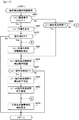
図3は、特別図柄プロセス処理の一例を示すフローチャートである。この特別図柄プロセス処理において、CPU103は、まず、始動入賞判定処理を実行する(ステップS101)。始動入賞判定処理では、第1始動口スイッチ22Aや第2始動口スイッチ22Bがオンであるか否かが判定される。このとき、第1始動口スイッチ22Aがオンであれば、普通入賞球装置6Aに形成された第1始動入賞口を遊技球が通過(進入)したことに基づいて、第1特図を用いた特図ゲームの保留記憶数である第1特図保留記憶数を更新するための第1始動入賞処理が行われる。一方、第2始動口スイッチ22Bがオンであれば、普通可変入賞球装置6Bに形成された第2始動入賞口を遊技球が通過(進入)したことに基づいて、第2特図を用いた特図ゲームの保留記憶数である第2特図保留記憶数を更新するための第2始動入賞処理が行われる。
FIG. 3 is a flowchart showing an example of the special symbol process. In this special symbol process, the
一例として、第1始動入賞処理では、第1特図保留記憶数が所定の上限値(例えば「4」)となっているか否かを判定する。このとき第1特図保留記憶数が上限値に達していれば、第1始動入賞処理を終了する。一方、第1特図保留記憶数が上限値未満であれば、RAM102の所定領域(例えば遊技制御カウンタ設定部)に設けられた第1保留記憶数カウンタの格納値である第1保留記憶数カウント値を1加算する。こうして、第1保留記憶数カウント値は、第1始動入賞口を遊技球が通過(進入)して第1特図を用いた特図ゲームに対応した第1始動条件が成立したときに、1増加(インクリメント)するように更新される。その後、始動入賞の発生に対応した所定の遊技用乱数を抽出して、RAM102の所定領域(例えば第1特図保留記憶部)に保留データ(保留情報)として記憶させる。
As an example, in the first start winning process, it is determined whether or not the first special figure holding memory number is a predetermined upper limit value (for example, “4”). At this time, if the first special figure reservation storage number has reached the upper limit value, the first start winning process is terminated. On the other hand, if the first special figure reserved memory number is less than the upper limit value, the first reserved memory number count that is the stored value of the first reserved memory number counter provided in a predetermined area of the RAM 102 (for example, the game control counter setting unit). Add 1 to the value. Thus, the first reserved memory number count value is 1 when the game ball passes (enters) the first start winning opening and the first start condition corresponding to the special figure game using the first special figure is satisfied. Updated to increase (increment). Thereafter, a predetermined game random number corresponding to the occurrence of the start winning is extracted and stored as hold data (hold information) in a predetermined area (for example, the first special figure hold storage unit) of the
第2始動入賞処理では、第2特図保留記憶数が所定の上限値(例えば「4」)となっているか否かを判定する。このとき第2特図保留記憶数が上限値に達していれば、第2始動入賞処理を終了する。一方、第2特図保留記憶数が上限値未満であれば、RAM102の所定領域(例えば遊技制御カウンタ設定部)に設けられた第2保留記憶数カウンタの格納値である第2保留記憶数カウント値を1加算する。こうして、第2保留記憶数カウント値は、第2始動入賞口を遊技球が通過(進入)して第2特図を用いた特図ゲームに対応した第2始動条件が成立したときに、1増加(インクリメント)するように更新される。その後、始動入賞の発生に対応した所定の遊技用乱数を抽出して、RAM102の所定領域(例えば第2特図保留記憶部)に保留データとして記憶させる。 In the second start winning process, it is determined whether or not the second special figure holding storage number is a predetermined upper limit value (for example, “4”). At this time, if the second special figure reservation storage number has reached the upper limit value, the second start winning process is terminated. On the other hand, if the second special figure reserved memory number is less than the upper limit value, the second reserved memory number count that is the stored value of the second reserved memory number counter provided in a predetermined area of the RAM 102 (for example, the game control counter setting unit). Add 1 to the value. Thus, the second reserved memory number count value is 1 when the game ball passes (enters) the second start winning opening and the second start condition corresponding to the special figure game using the second special figure is satisfied. Updated to increase (increment). Thereafter, a predetermined game random number corresponding to the occurrence of the start winning is extracted and stored as reserved data in a predetermined area of the RAM 102 (for example, the second special figure storage unit).
図3に示すステップS101にて始動入賞判定処理を実行した後、CPU103は、RAM102の所定領域(遊技制御フラグ設定部など)に設けられた特図プロセスフラグの値に応じて、ステップS110〜S117の処理のいずれかを選択して実行する。
After executing the start winning determination process in step S101 shown in FIG. 3, the
ステップS110の特別図柄通常処理は、特図プロセスフラグの値が“0”のときに実行される。この特別図柄通常処理では、第1特図保留記憶部151Aや第2特図保留記憶部151Bに記憶されている保留データの有無などに基づいて、第1特別図柄表示装置4Aや第2特別図柄表示装置4Bによる特図ゲームを開始するか否かの判定が行われる。また、特別図柄通常処理では、特図表示結果決定用の乱数値MR1を示す数値データに基づき、特別図柄や飾り図柄の可変表示結果を「大当り」とするか否かを、その可変表示結果が導出表示される以前に決定(事前決定)する。さらに、特別図柄通常処理では、特図ゲームにおける特別図柄の可変表示結果に対応して、第1特別図柄表示装置4Aや第2特別図柄表示装置4Bによる特図ゲームにおける確定特別図柄(大当り図柄やハズレ図柄のいずれか)が設定される。特別図柄通常処理では、特別図柄や飾り図柄の可変表示結果を事前決定したときに、特図プロセスフラグの値が“1”に更新される。
The special symbol normal process in step S110 is executed when the value of the special symbol process flag is “0”. In this special symbol normal processing, the first special
ステップS111の変動パターン設定処理は、特図プロセスフラグの値が“1”のときに実行される。この変動パターン設定処理には、可変表示結果を「大当り」とするか否かの事前決定結果などに基づいて、変動パターンを複数種類のいずれかに決定する処理などが含まれている。特別図柄や飾り図柄の可変表示時間は、変動パターンに対応して予め設定されている。したがって、変動パターン設定処理にて変動パターンを決定することにより、特別図柄の可変表示を開始してから可変表示結果となる確定特別図柄を導出するまでの可変表示時間が決定される。また、変動パターン設定処理は、可変表示結果が「ハズレ」となる場合に、飾り図柄の可変表示態様を「リーチ」とするか否かを決定する処理を含んでもよい。あるいは、変動パターン設定処理にて可変表示結果が「ハズレ」となる場合の変動パターンを所定割合で決定することにより、飾り図柄の可変表示態様を「リーチ」とするか否かが決定されてもよい。さらに、変動パターン設定処理は、第1特別図柄表示装置4Aや第2特別図柄表示装置4Bにおいて特別図柄の変動を開始させるための設定を行う処理を含んでもよい。変動パターン設定処理が実行されたときには、特図プロセスフラグの値が“2”に更新される。
The variation pattern setting process in step S111 is executed when the value of the special figure process flag is “1”. This variation pattern setting process includes a process of determining a variation pattern as one of a plurality of types based on a result of prior determination as to whether or not the variable display result is “big hit”. The variable display time for special symbols and decorative symbols is set in advance corresponding to the variation pattern. Accordingly, by determining the variation pattern in the variation pattern setting process, the variable display time from the start of variable display of the special symbol to the deriving of the definite special symbol resulting in the variable display result is determined. In addition, the variation pattern setting process may include a process of determining whether or not the variable display mode of the decorative symbol is “reach” when the variable display result is “losing”. Alternatively, even if it is determined whether or not the variable display mode of the decorative symbol is set to “reach” by determining the fluctuation pattern when the variable display result is “lost” in the fluctuation pattern setting process at a predetermined ratio. Good. Furthermore, the variation pattern setting process may include a process of performing setting for starting the variation of the special symbol in the first special
ステップS112の特別図柄変動処理は、特図プロセスフラグの値が“2”のときに実行される。この特別図柄変動処理には、第1特別図柄表示装置4Aや第2特別図柄表示装置4Bにおいて特別図柄を変動させるための設定を行う処理や、その特別図柄が変動を開始してからの経過時間を計測する処理などが含まれている。そして、特別図柄の変動を開始してからの経過時間が特図変動時間に達したときには、特図プロセスフラグの値が“3”に更新される。
The special symbol variation process in step S112 is executed when the value of the special symbol process flag is “2”. The special symbol variation process includes a process for performing setting for varying the special symbol in the first special
ステップS113の特別図柄停止処理は、特図プロセスフラグの値が“3”のときに実行される。この特別図柄停止処理には、第1特別図柄表示装置4Aや第2特別図柄表示装置4Bにて特別図柄の変動を停止させ、特別図柄の可変表示結果となる確定特別図柄を停止表示させるための設定を行う処理が含まれている。そして、RAM102の所定領域(遊技制御フラグ設定部など)に設けられた大当りフラグがオンとなっているか否かの判定などが行われる。大当りフラグがオンである場合には、特図表示結果が「大当り」であることに基づく大当り遊技状態の開始を指定する当り開始指定コマンドの送信設定を行うとともに、特図プロセスフラグの値を“4”に更新する。大当りフラグがオフである場合には、特図プロセスフラグの値を“0”に更新する。
The special symbol stop process in step S113 is executed when the value of the special symbol process flag is “3”. In the special symbol stop process, the first special
ステップS114の大当り開放前処理は、特図プロセスフラグの値が“4”のときに実行される。この大当り開放前処理には、可変表示結果が「大当り」となったことなどに基づき、大当り遊技状態においてラウンド遊技の実行を開始して大入賞口を開放状態とするための設定を行う処理などが含まれている。この処理では、例えば大入賞口を開放状態とする期間の上限を「29秒」に設定することにより、通常開放ラウンドが実行されるようにすればよい。なお、大当り種別に「突確」を設けた場合には、大入賞口を開放状態とする期間の上限を「0.1秒」に設定することにより、短期開放ラウンドが実行されるようにすればよい。大当り開放前処理が実行されたときには、特図プロセスフラグの値が“5”に更新される。 The big hit release pre-processing in step S114 is executed when the value of the special figure process flag is “4”. The pre-opening process for the big hit is based on the fact that the variable display result is “big hit”, etc., and the process for starting the execution of the round game in the big hit gaming state and setting the winning prize opening to the open state, etc. It is included. In this process, for example, the upper limit of the period during which the special winning opening is opened may be set to “29 seconds” so that the normal opening round is executed. In addition, when “surprise” is provided for the big hit type, if the upper limit of the period during which the big winning opening is opened is set to “0.1 second”, the short-term open round is executed. Good. When the big hit release pre-processing is executed, the value of the special figure process flag is updated to “5”.
ステップS115の大当り開放中処理は、特図プロセスフラグの値が“5”のときに実行される。この大当り開放中処理には、大入賞口を開放状態としてからの経過時間を計測する処理や、その計測した経過時間やカウントスイッチ23によって検出された遊技球の個数などに基づいて、大入賞口を開放状態から閉鎖状態に戻すタイミングとなったか否かを判定する処理などが含まれている。そして、大入賞口を閉鎖状態に戻したときには、特図プロセスフラグの値が“6”に更新される。 The big hit release processing in step S115 is executed when the value of the special figure process flag is “5”. In the big hit opening process, the winning prize opening is based on the process of measuring the elapsed time since the big winning opening is in the open state, the measured elapsed time, the number of game balls detected by the count switch 23, and the like. The process etc. which determine whether it became the timing which returns to a closed state from an open state are included. When the special winning opening is returned to the closed state, the value of the special figure process flag is updated to “6”.
ステップS116の大当り開放後処理は、特図プロセスフラグの値が“6”のときに実行される。この大当り開放後処理には、大入賞口を開放状態とするラウンド遊技の実行回数が所定の上限回数に達したか否かを判定する処理や、上限回数に達していない場合に次回のラウンド遊技が開始されるまで待機する処理などが含まれている。そして、次回のラウンド遊技が開始されるときには、特図プロセスフラグの値が“4”に更新される一方、ラウンド遊技の実行回数が上限回数に達したときには、特図プロセスフラグの値が“7”に更新される。 The big hit release post-processing in step S116 is executed when the value of the special figure process flag is “6”. In this post-hit opening process, a process for determining whether or not the number of executions of the round game in which the big winning opening is in an open state has reached a predetermined upper limit number, or the next round game when the upper limit number has not been reached. Processing that waits until the start is included. When the next round game is started, the value of the special figure process flag is updated to “4”, while when the number of executions of the round game reaches the upper limit number, the value of the special figure process flag is “7”. Is updated.
ステップS117の大当り終了処理は、特図プロセスフラグの値が“7”のときに実行される。この大当り終了処理には、画像表示装置5やスピーカ8L、8R、遊技効果ランプ9などといった演出装置により、大当り遊技状態の終了を報知する演出動作としてのエンディング演出が実行される期間に対応した待ち時間が経過するまで待機する処理や、確変制御条件の成否に対応して確変状態や時短状態に制御するための各種の設定を行う処理などが含まれている。例えば、大当り種別が「確変」であるか「非確変」であるかに応じて、確変状態や時短状態に制御するための設定が行われる。その後、特図プロセスフラグの値が“0”に更新される。
The big hit end process in step S117 is executed when the value of the special figure process flag is “7”. In the jackpot end process, a waiting time corresponding to a period in which an ending effect as an effect operation for notifying the end of the jackpot game state is executed by an effect device such as the
図4は、特別図柄通常処理として、図3のステップS110にて実行される処理の一例を示すフローチャートである。図4に示す特別図柄通常処理において、CPU103は、まず、第2特図保留記憶数が「0」であるか否かを判定する(ステップS231)。第2特図保留記憶数は、第2特別図柄表示装置4Bによる第2特図を用いた特図ゲームの保留記憶数である。CPU103は、第2保留記憶数カウント値を読み出し、その読出値が「0」であるか否かを判定すればよい。
FIG. 4 is a flowchart showing an example of the process executed in step S110 of FIG. 3 as the special symbol normal process. In the special symbol normal process shown in FIG. 4, the
ステップS231にて第2特図保留記憶数が「0」以外であるときには(ステップS231;No)、例えば第2特図保留記憶部の先頭領域(例えば保留番号「1」に対応する記憶領域)といった、RAM102の所定領域に記憶されている保留データとして、所定の乱数値を示す数値データを読み出す(ステップS232)。これにより、図3に示すステップS101の始動入賞判定処理で第2始動入賞口における始動入賞(第2始動入賞)の発生に対応して抽出された遊技用乱数が読み出される。このとき読み出された数値データは、例えば変動用乱数バッファなどに格納されて、一時記憶されればよい。 When the second special figure reservation storage number is other than “0” in step S231 (step S231; No), for example, the first area of the second special figure reservation storage unit (for example, the storage area corresponding to the reservation number “1”) The numerical data indicating a predetermined random number value is read as the hold data stored in the predetermined area of the RAM 102 (step S232). Thereby, the game random numbers extracted in response to the occurrence of the start winning (second start winning) at the second start winning opening in the start winning determination process of step S101 shown in FIG. 3 are read. The numerical data read at this time may be temporarily stored, for example, in a random number buffer for variation.
ステップS232の処理に続いて、例えば第2保留記憶数カウント値を1減算して更新することなどにより、第2特図保留記憶数を1減算させるように更新するとともに、第2特図保留記憶部における記憶内容をシフトさせる(ステップS233)。例えば、第2特図保留記憶部にて保留番号「1」より下位の記憶領域(保留番号「2」〜「4」に対応する記憶領域)に記憶された保留データを、1エントリずつ上位にシフトする。また、ステップS233の処理では、合計保留記憶数を1減算するように更新してもよい。そして、RAM102の所定領域(例えば遊技制御バッファ設定部)に設けられた変動特図指定バッファの格納値である変動特図指定バッファ値を、「2」に更新する(ステップS234)。
Subsequent to the processing of step S232, for example, by subtracting and updating the second reserved memory number count value by 1, etc., the second special figure reserved memory number is updated by 1 and the second special figure reserved memory is also updated. The stored contents in the unit are shifted (step S233). For example, the second special figure hold storage unit stores the hold data stored in the storage area lower than the hold number “1” (the storage area corresponding to the hold numbers “2” to “4”) one entry at a time. shift. Further, in the process of step S233, the total number of reserved storages may be updated to be subtracted by one. Then, the variation special figure designation buffer value, which is the stored value of the fluctuation special figure designation buffer provided in a predetermined area (for example, the game control buffer setting unit) of the
ステップS231にて第2特図保留記憶数が「0」であるときには(ステップS231;Yes)、第1特図保留記憶数が「0」であるか否かを判定する(ステップS235)。第1特図保留記憶数は、第1特別図柄表示装置4Aによる第1特図を用いた特図ゲームの保留記憶数である。CPU103は、第1保留記憶数カウント値を読み出し、その読出値が「0」であるか否かを判定すればよい。このように、ステップS235の処理は、ステップS231にて第2特図保留記憶数が「0」であると判定されたときに実行されて、第1特図保留記憶数が「0」であるか否かを判定する。これにより、第2特図を用いた特図ゲームは、第1特図を用いた特図ゲームよりも優先して実行が開始されることになる。
When the second special figure reserved memory number is “0” in step S231 (step S231; Yes), it is determined whether or not the first special figure reserved memory number is “0” (step S235). The first special figure reserved memory number is the reserved memory number of the special figure game using the first special figure by the first special
なお、第2特図を用いた特図ゲームが第1特図を用いた特図ゲームよりも優先して実行されるものに限定されない。すなわち、第1始動入賞口であるか第2始動入賞口であるかにかかわらず、遊技球が始動入賞口を通過(進入)した順番で、特図ゲームが実行されるようにしてもよい。この場合には、第1始動入賞口と第2始動入賞口のいずれを遊技球が通過(進入)したかを示す始動口データを、保留データとともに、あるいは保留データとは別個に、保留番号と対応付けてRAM102の所定領域に記憶させておき、それぞれの保留データに対応する特図ゲームについて、始動条件が成立した順番を特定可能にすればよい。
The special figure game using the second special figure is not limited to the one executed with priority over the special figure game using the first special figure. In other words, the special game may be executed in the order in which the game balls have passed (entered) the start winning opening regardless of the first starting winning opening or the second starting winning opening. In this case, the start opening data indicating whether the game ball has passed (entered) through the first start winning opening or the second starting winning opening is stored with the hold data or separately from the hold data and the hold number. It is possible to store them in a predetermined area of the
ステップS235にて第1特図保留記憶数が「0」以外であるときには(ステップS235;No)、例えば第1特図保留記憶部の先頭領域(例えば保留番号「1」に対応する記憶領域)といった、RAM102の所定領域に記憶されている保留データとして、所定の乱数値を示す数値データを読み出す(ステップS236)。これにより、図3に示すステップS101の始動入賞判定処理で第1始動入賞口における始動入賞(第1始動入賞)の発生に対応して抽出された遊技用乱数が読み出される。このとき読み出された数値データは、例えば変動用乱数バッファなどに格納されて、一時記憶されればよい。 When the first special figure reservation storage number is other than “0” in step S235 (step S235; No), for example, the first area of the first special figure reservation storage unit (for example, the storage area corresponding to the reservation number “1”) The numerical data indicating a predetermined random number value is read as the hold data stored in the predetermined area of the RAM 102 (step S236). Thereby, the game random number extracted in response to the occurrence of the start winning (first start winning) at the first start winning opening in the start winning determination process of step S101 shown in FIG. 3 is read. The numerical data read at this time may be temporarily stored, for example, in a random number buffer for variation.
ステップS236の処理に続いて、例えば第1保留記憶数カウント値を1減算して更新することなどにより、第1特図保留記憶数を1減算させるように更新するとともに、第1特図保留記憶部における記憶内容をシフトさせる(ステップS237)。例えば、第1特図保留記憶部にて保留番号「1」より下位の記憶領域(保留番号「2」〜「4」に対応する記憶領域)に記憶された保留データを、1エントリずつ上位にシフトする。また、ステップS237の処理では、合計保留記憶数を1減算するように更新してもよい。そして、変動特図指定バッファ値を「1」に更新する(ステップS238)。 Subsequent to the process of step S236, for example, by updating the first reserved memory number count value by subtracting 1 and updating the first special figure reserved memory number, the first special figure reserved memory is updated. The stored contents in the unit are shifted (step S237). For example, the first special figure reservation storage unit stores the hold data stored in the storage area lower than the hold number “1” (the storage area corresponding to the hold numbers “2” to “4”) one entry at a time. shift. Further, in the process of step S237, the total number of reserved storages may be updated to be decremented by 1. Then, the variable special figure designation buffer value is updated to “1” (step S238).
ステップS234、S238の処理のいずれかを実行した後には、特別図柄の可変表示結果である特図表示結果を、「大当り」と「ハズレ」のいずれかに決定する(ステップS239)。一例として、ステップS239の処理では、予めROM101の所定領域に記憶するなどして用意された特図表示結果決定テーブルを選択し、特図表示結果を決定するための使用テーブルに設定する。特図表示結果決定テーブルでは、特図表示結果決定用の乱数値MR1と比較される数値(決定値)が、特図表示結果を「大当り」と「ハズレ」のいずれとするかの決定結果に、割り当てられていればよい。CPU103は、変動用乱数バッファから読み出した特図表示結果決定用の乱数値MR1を示す数値データに基づいて、特図表示結果決定テーブルを参照することにより、特図表示結果を決定すればよい。
After executing one of the processes of steps S234 and S238, the special figure display result, which is the special symbol variable display result, is determined as either “big hit” or “losing” (step S239). As an example, in the process of step S239, a special figure display result determination table prepared by storing in a predetermined area of the
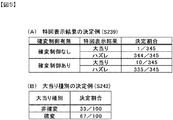
図5(A)は、ステップS239の処理による特図表示結果の決定例を示している。このように、特図表示結果を「大当り」と「ハズレ」のいずれとするかが、特図表示結果決定用の乱数値MR1を示す数値データや特図表示結果決定テーブルを用いて、所定割合で決定されればよい。図5(A)に示す決定例では、確変状態における確変制御の有無に応じて、特図表示結果を「大当り」とするか否かの決定割合を異ならせている。CPU103は、RAM102の所定領域(遊技制御フラグ設定部など)に設けられた確変フラグがオンである場合に、確変制御が行われていると判定すればよい。
FIG. 5A shows an example of determining the special figure display result by the process of step S239. As described above, whether the special figure display result is “big hit” or “losing” is determined by using the numerical data indicating the random value MR1 for determining the special figure display result and the special figure display result determination table. It may be determined by. In the determination example shown in FIG. 5A, the determination ratio of whether or not the special figure display result is “big hit” is varied depending on the presence or absence of probability variation control in the probability variation state. The
図5(A)に示すように、確変状態にて確変制御が行われているときには、通常状態や時短状態にて確変制御が行われていないときよりも高い割合で、特図表示結果が「大当り」に決定される。したがって、例えば図3に示すステップS117の大当り終了処理により、大当り種別が「確変」であった場合に対応して確変フラグがオン状態にセットされたことなどに基づいて、確変制御が行われる確変状態であるときには、通常状態や時短状態にて確変制御が行われていないときよりも、特図表示結果が「大当り」になりやすく、大当り遊技状態になりやすい。 As shown in FIG. 5 (A), when the probability variation control is performed in the probability variation state, the special figure display result is “a higher rate than when the probability variation control is not performed in the normal state or the time reduction state. "Big hit" is decided. Therefore, for example, in the jackpot ending process in step S117 shown in FIG. 3, the probability change in which the probability change control is performed based on the fact that the probability change flag is set to the on state corresponding to the case where the jackpot type is “probability change”. In the state, the special figure display result is more likely to be “big hit” and more likely to be in the big hit gaming state than when the probability variation control is not performed in the normal state or the short time state.
この実施の形態では、第1特別図柄表示装置4Aによる第1特図を用いた特図ゲームであるか、第2特別図柄表示装置4Bによる第2特図を用いた特図ゲームであるかにかかわらず、確変制御の有無に応じた所定割合で特図表示結果が決定される。これに対して、第1特別図柄表示装置4Aによる特図ゲームの場合と、第2特別図柄表示装置4Bによる特図ゲームの場合のそれぞれに対応して、特図表示結果に対する決定値の割当てが異なる決定テーブルを用意してもよい。この場合には、第1特別図柄表示装置4Aによる特図ゲームの場合と、第2特別図柄表示装置4Bによる特図ゲームの場合とでは、所定の特図表示結果に対する決定値の割当てを異ならせてもよい。
In this embodiment, whether the game is a special game using the first special symbol by the first special
その後、CPU103は、ステップS239の処理により決定された特図表示結果が「大当り」であるか否かを判定する(ステップS240)。特図表示結果が「大当り」に決定された場合には(ステップS240;Yes)、RAM102の所定領域(遊技制御フラグ設定部など)に設けられた大当りフラグをオン状態にセットする(ステップS241)。また、大当り種別を複数種類のいずれかに決定する(ステップS242)。一例として、ステップS242の処理では、予めROM101の所定領域に記憶するなどして用意された大当り種別決定テーブルを選択し、大当り種別を決定するための使用テーブルに設定する。大当り種別決定テーブルでは、大当り種別決定用の乱数値と比較される数値(決定値)が、大当り種別を複数種類のいずれとするかの決定結果に、割り当てられていればよい。CPU103は、変動用乱数バッファから読み出した大当り種別決定用の乱数値MR2を示す数値データに基づいて、大当り種別決定テーブルを参照することにより、大当り種別を決定すればよい。
Thereafter, the
図5(B)は、ステップS242の処理による大当り種別の決定例を示している。この決定例では、変動特図が第1特図であるか第2特図であるかにかかわらず、所定割合で大当り種別が「非確変」と「確変」のいずれかに決定される。なお、変動特図が第1特図であるか第2特図であるかに応じて、決定可能な大当り種別を異ならせてもよいし、大当り種別の決定割合を異ならせてもよい。一例として、変動特図が第1特図である場合には所定割合で大当り種別が「突確」に決定可能とする一方、変動特図が第2特図である場合には大当り種別が「突確」には決定されないように設定してもよい。 FIG. 5B shows an example of determining the jackpot type by the process of step S242. In this determination example, regardless of whether the fluctuation special chart is the first special chart or the second special chart, the big hit type is determined to be “non-probable change” or “probability change” at a predetermined rate. Depending on whether the variation special chart is the first special chart or the second special chart, the determinable jackpot type may be varied, or the determination ratio of the jackpot type may be varied. As an example, when the fluctuation special chart is the first special figure, the big hit type can be determined as “surprise” at a predetermined rate, while when the fluctuation special figure is the second special figure, the big hit type is “surprise”. May be set so as not to be determined.
ステップS242の処理を実行した後には、大当り種別を記憶させる(ステップS243)。CPU103は、RAM102の所定領域(遊技制御バッファ設定部など)に設けられた大当り種別バッファに、大当り種別の決定結果を示すデータを格納することにより、大当り種別を記憶させればよい。
After executing the process of step S242, the big hit type is stored (step S243). The
ステップS240にて特図表示結果が「大当り」ではない場合や(ステップS240;No)、ステップS243の処理を実行した後には、特図ゲームにおける特別図柄の可変表示結果となる確定特別図柄を決定する(ステップS244)。一例として、ステップS240にて特図表示結果が「大当り」ではないと判定された場合には、ハズレ図柄として予め定められた「−」の記号を示す特別図柄を、確定特別図柄に決定する。一方、ステップS240にて特図表示結果が「大当り」であると判定された場合には、ステップS242における大当り種別の決定結果に応じて、複数種類の大当り図柄として予め定められた特別図柄のいずれかを確定特別図柄に決定すればよい。より具体的には、大当り種別が「非確変」の場合には「3」の数字を示す特別図柄を、確定特別図柄に決定すればよい。大当り種別が「確変」の場合には「7」の数字を示す特別図柄を、確定特別図柄に決定すればよい。 When the special figure display result is not “big hit” in step S240 (step S240; No), or after executing the process of step S243, a fixed special symbol that becomes a variable display result of the special symbol in the special figure game is determined. (Step S244). As an example, when it is determined in step S240 that the special symbol display result is not “big hit”, the special symbol indicating the symbol “−” predetermined as the lost symbol is determined as the confirmed special symbol. On the other hand, if it is determined in step S240 that the special figure display result is “big hit”, any of the special symbols predetermined as a plurality of types of big hit symbols is determined according to the determination result of the big hit type in step S242. Can be determined as a confirmed special symbol. More specifically, when the jackpot type is “non-probable change”, the special symbol indicating the number “3” may be determined as the confirmed special symbol. When the big hit type is “probability change”, the special symbol indicating the number “7” may be determined as the confirmed special symbol.
ステップS244の処理を実行した後には、特図プロセスフラグの値を“1”に更新してから(ステップS245)、特別図柄通常処理を終了する。ステップS245の処理にて特図プロセスフラグの値が“1”に更新されることにより、次回のタイマ割込みが発生したときには、図3に示すステップS111の変動パターン設定処理が実行される。 After executing the process of step S244, the value of the special figure process flag is updated to “1” (step S245), and then the special symbol normal process is terminated. When the value of the special figure process flag is updated to “1” in the process of step S245, and the next timer interruption occurs, the variation pattern setting process of step S111 shown in FIG. 3 is executed.
ステップS235にて第1特図を用いた特図ゲームの保留記憶数が「0」である場合には(ステップS235;Yes)、所定のデモ表示設定を行ってから(ステップS246)、特別図柄通常処理を終了する。このデモ表示設定では、例えば画像表示装置5において所定の演出画像を表示することなどによるデモンストレーション表示(デモ画面表示)を指定する演出制御コマンド(客待ちデモ指定コマンド)が、主基板11から演出制御基板12に対して送信済みであるか否かを判定する。このとき、送信済みであれば、そのままデモ表示設定を終了する。これに対して、未送信であれば、客待ちデモ指定コマンドを送信するための設定を行ってから、デモ表示設定を終了する。
In step S235, when the number of reserved memories of the special figure game using the first special figure is “0” (step S235; Yes), after performing a predetermined demonstration display setting (step S246), the special symbol is set. End normal processing. In this demonstration display setting, for example, an effect control command (customer waiting demonstration designation command) for designating demonstration display (demonstration screen display) by displaying a predetermined effect image on the
図6(A)は、変動パターン設定処理として、図3のステップS111にて実行される処理の一例を示すフローチャートである。図6(A)に示す変動パターン設定処理において、CPU103は、まず、大当りフラグがオンであるか否かを判定する(ステップS261)。そして、大当りフラグがオンである場合には(ステップS261;Yes)、特図表示結果が「大当り」となる大当り時に対応した変動パターンを決定する(ステップS262)。一方、大当りフラグがオフである場合には(ステップS261;No)、特図表示結果が「ハズレ」となるハズレ時に対応した変動パターンを決定する(ステップS263)。
FIG. 6A is a flowchart illustrating an example of a process executed in step S111 in FIG. 3 as the variation pattern setting process. In the variation pattern setting process shown in FIG. 6A, the
図6(B)は、この実施の形態における変動パターンを示している。この実施の形態では、可変表示結果(特図表示結果)が「ハズレ」となる場合のうち、飾り図柄の可変表示態様がリーチ態様にはならない「非リーチ」である場合とリーチ態様になる「リーチ」である場合のそれぞれに対応して、また、可変表示結果(特図表示結果)が「大当り」となる場合などに対応して、複数の変動パターンが予め用意されている。 FIG. 6B shows the variation pattern in this embodiment. In this embodiment, among the cases where the variable display result (special drawing display result) is “losing”, the decorative display variable display mode is “non-reach” that does not become the reach mode, and the reach mode is “ A plurality of variation patterns are prepared in advance corresponding to each of the cases of “reach” and corresponding to the case where the variable display result (special drawing display result) is “big hit”.
図6(A)に示すステップS262の処理では、例えば予めROM101の所定領域に記憶するなどして用意された大当り変動パターン決定テーブルを用いて、大当り時の変動パターンが決定される。大当り変動パターン決定テーブルでは、大当り種別が「非確変」であるか「確変」であるかに応じて、変動パターン決定用の乱数値MR3と比較される数値(決定値)が、変動パターンの決定結果に、割り当てられていればよい。CPU103は、変動用乱数バッファから読み出した変動パターン決定用の乱数値MR3を示す数値データに基づいて、大当り変動パターン決定テーブルを参照することにより、可変表示結果が「大当り」となる場合に対応した変動パターンを決定すればよい。
In the process of step S262 shown in FIG. 6A, the variation pattern at the time of big hit is determined using a big hit variation pattern determination table prepared by storing in a predetermined area of the
図6(A)に示すステップS263の処理では、遊技状態が通常状態である通常時の場合と、遊技状態が確変状態や時短状態で時短制御が行われる時短中の場合とに対応して、予め用意した複数のハズレ変動パターン決定テーブルのいずれかを用いて、ハズレ時の変動パターンが決定される。複数のハズレ変動パターン決定テーブルでは、通常時であるか時短中であるかや、合計保留記憶数に応じて、変動パターン決定用の乱数値MR3と比較される数値(決定値)が、変動パターンの決定結果に、割り当てられていればよい。CPU103は、変動用乱数バッファから読み出した変動パターン決定用の乱数値MR3を示す数値データに基づいて、通常時と時短中とに応じたハズレ変動パターン決定テーブルのいずれかを参照することにより、可変表示結果が「ハズレ」となる場合に対応した変動パターンを決定すればよい。
In the process of step S263 shown in FIG. 6 (A), corresponding to the normal time when the game state is the normal state and the short time control when the game state is the probability changing state or the short time state, The variation pattern at the time of losing is determined using any of a plurality of losing variation pattern determination tables prepared in advance. In the plurality of loss variation pattern determination tables, a numerical value (determination value) to be compared with the random value MR3 for determining a variation pattern is a variation pattern according to whether it is normal time or short of time, and according to the total number of reserved memories It is only necessary to be assigned to the determination result. The
ハズレ変動パターン決定テーブルでは、合計保留記憶数が所定数(例えば「2」)以上であるときに、所定数未満であるときよりも高い割合で、飾り図柄の可変表示態様が「非リーチ」に決定されるように、決定値が割り当てられていればよい。このように、特図保留記憶数が所定数以上であるときには、所定数未満であるときよりも飾り図柄の可変表示態様がリーチ態様に決定されにくいように設定されていればよい。これにより、特図保留記憶数が比較的に多いときには、比較的に少ないときよりも平均的な可変表示時間を短縮して、無効な始動入賞の発生を抑制することや、遊技者による遊技球の発射停止(いわゆる「止め打ち」)を低減することができる。 In the loss variation pattern determination table, when the total number of reserved memories is equal to or greater than a predetermined number (for example, “2”), the decorative symbol variable display mode is set to “non-reach” at a higher rate than when the total number is less than the predetermined number. It is sufficient that a decision value is assigned so as to be decided. In this way, when the number of special figure reservations stored is equal to or greater than a predetermined number, the decorative symbol variable display mode may be set to be less likely to be determined as the reach mode than when it is less than the predetermined number. As a result, when the number of special figure hold memory is relatively large, the average variable display time can be shortened compared to when the number of special figure storage is relatively small, and the occurrence of invalid start winnings can be suppressed. Can be reduced.
図7(A)は、大当り時における変動パターンの決定例を示している。この決定例では、変動パターンPA3−1といった、ノーマルのリーチ演出が実行される変動パターンの決定割合が、変動パターンPA3−2、PA3−3、PA3−4といったスーパーリーチのリーチ演出が実行される変動パターンの決定割合よりも低くなるように設定されている。 FIG. 7A shows an example of determining a variation pattern at the time of big hit. In this determination example, the determination ratio of the fluctuation pattern in which the normal reach effect such as the fluctuation pattern PA3-1 is executed is the super reach reach effect such as the fluctuation patterns PA3-2, PA3-3, and PA3-4. It is set to be lower than the determination rate of the fluctuation pattern.
図7(B)は、ハズレ時における変動パターンの決定例を示している。この決定例では、変動パターンPA2−1といった、ノーマルのリーチ演出が実行される変動パターンの決定割合が、変動パターンPA2−2、PA2−3、PA2−4といったスーパーリーチのリーチ演出が実行される変動パターンの決定割合よりも高くなるように設定されている。 FIG. 7B shows an example of determining the variation pattern at the time of loss. In this determination example, the determination ratio of the fluctuation pattern in which the normal reach effect is executed, such as the change pattern PA2-1, is executed, and the reach effect of the super reach such as the change patterns PA2-2, PA2-3, PA2-4 is executed. It is set to be higher than the determination rate of the fluctuation pattern.
また、大当り時には、スーパーリーチのリーチ演出が実行される変動パターンの決定割合が、ハズレ時よりも高くなるように設定されている。これにより、スーパーリーチのリーチ演出が実行されてから可変表示結果が導出されるときには、その可変表示結果が「大当り」となる可能性(大当り期待度)が高められる。また、スーパーCのリーチ演出が実行されてから可変表示結果が導出されるときには、スーパーBのリーチ演出が実行されてから可変表示結果が導出されるときと比べて、その可変表示結果が「大当り」となる可能性(大当り期待度)が高められ、スーパーBのリーチ演出が実行されてから可変表示結果が導出されるときには、スーパーAのリーチ演出が実行されてから可変表示結果が導出されるときと比べて、その可変表示結果が「大当り」となる可能性(大当り期待度)が高められる。 Moreover, at the time of big hit, the determination ratio of the fluctuation pattern in which the reach effect of super reach is executed is set to be higher than that at the time of loss. Thereby, when the variable display result is derived after the reach effect of the super reach is executed, the possibility that the variable display result becomes “big hit” (expected degree of big hit) is increased. Also, when the variable display result is derived after the Super C reach effect is executed, the variable display result is “big hit” compared to when the variable B display result is derived after the Super B reach effect is executed. When the variable display result is derived after the Super B reach effect is executed, the variable display result is derived after the Super A reach effect is executed. Compared to the time, the possibility that the variable display result will be a “big hit” (expected degree of big hit) is increased.
図7(A)に示す決定例において、変動パターンPA3−4といった、スーパーCのリーチ演出が実行される変動パターンの決定割合が、変動パターンPA3−3といった、スーパーBのリーチ演出が実行される変動パターンの決定割合よりも高くなるように設定され、変動パターンPA3−3といった、スーパーBのリーチ演出が実行される変動パターンの決定割合が、変動パターンPA3−2といった、スーパーAのリーチ演出が実行される変動パターンの決定割合よりも高くなるように設定されている。一方、図7(B)に示す決定例において、変動パターンPA2−4といった、スーパーCのリーチ演出が実行される変動パターンの決定割合が、変動パターンPA2−3といった、スーパーBのリーチ演出が実行される変動パターンの決定割合よりも低くなるように設定され、変動パターンPA2−3といった、スーパーBのリーチ演出が実行される変動パターンの決定割合が、変動パターンPA2−2といった、スーパーAのリーチ演出が実行される変動パターンの決定割合よりも低くなるように設定されている。また、大当り時には、スーパーリーチのリーチ演出が実行される変動パターンの決定割合が、ハズレ時よりも十分に高くなるように設定されている。したがって、可変表示結果が「大当り」となって遊技状態が大当り遊技状態となる場合には、大当り遊技状態とならない場合よりも高い割合で、スーパーリーチのリーチ演出が実行されてから可変表示結果が導出される。 In the example of determination shown in FIG. 7A, the determination ratio of the fluctuation pattern in which the super C reach effect such as the fluctuation pattern PA3-4 is executed is executed in the super B reach effect such as the fluctuation pattern PA3-3. The determination ratio of the fluctuation pattern that is set to be higher than the determination ratio of the fluctuation pattern and executes the reach effect of Super B such as the fluctuation pattern PA3-3 is the reach effect of Super A such as the fluctuation pattern PA3-2. It is set to be higher than the determination ratio of the variation pattern to be executed. On the other hand, in the example of determination shown in FIG. 7B, the determination ratio of the fluctuation pattern in which the super C reach effect such as the fluctuation pattern PA2-4 is executed is the super B reach effect such as the fluctuation pattern PA2-3. Is set to be lower than the determination ratio of the fluctuation pattern to be performed, and the determination ratio of the fluctuation pattern such as the fluctuation pattern PA2-3 where the super B reach effect is executed is the reach of the super A such as the fluctuation pattern PA2-2. It is set to be lower than the determination ratio of the variation pattern in which the effect is executed. Moreover, at the time of big hit, the determination ratio of the variation pattern in which the reach effect of the super reach is executed is set to be sufficiently higher than that at the time of losing. Therefore, when the variable display result is “big hit” and the gaming state becomes the big hit gaming state, the variable display result is obtained after the reach effect of super reach is executed at a higher rate than when the big hit gaming state is not reached. Derived.
図6(B)に示すように、変動パターンPA2−1〜PA2−4と、変動パターンPA3−1〜PA3−4とでは、特図変動時間や内容が共通している一方で、可変表示結果が「ハズレ」となるか「大当り」となるかが異なっている。図7(A)および(B)に示す決定割合の設定により、スーパーリーチのリーチ演出が実行されたときには、ノーマルのリーチ演出が実行されたときよりも大当り期待度が高められる。また、スーパーCのリーチ演出が実行されたときには、スーパーBのリーチ演出が実行されたときよりも大当り期待度が高められ、スーパーBのリーチ演出が実行されたときには、スーパーAのリーチ演出が実行されたときよりも大当り期待度が高められる。 As shown in FIG. 6B, the variation patterns PA2-1 to PA2-4 and the variation patterns PA3-1 to PA3-4 have the same special diagram variation time and content, but the variable display result. Will be “lost” or “big hit”. With the determination ratio setting shown in FIGS. 7A and 7B, when the super reach reach effect is executed, the big hit expectation is higher than when the normal reach effect is executed. Also, when the Super C reach effect is executed, the big hit expectation is higher than when the Super B reach effect is executed, and when the Super B reach effect is executed, the Super A reach effect is executed. Big hit expectation is higher than when it was done.
ステップS262、S263の処理のいずれかを実行した後には、特別図柄の可変表示時間である特図変動時間を設定する(ステップS264)。特別図柄の可変表示時間となる特図変動時間は、特図ゲームにおいて特別図柄の変動を開始してから可変表示結果(特図表示結果)となる確定特別図柄が導出表示されるまでの所要時間である。特図変動時間は、図6(B)に示すように、予め用意された複数の変動パターンに対応して、予め定められている。CPU103は、特図変動時間を設定することにより、特別図柄や飾り図柄の可変表示結果が導出されるタイミングを設定できる。
After executing one of the processes in steps S262 and S263, a special figure change time which is a variable symbol display time is set (step S264). The special figure change time, which is the variable display time of the special symbol, is the time required from the start of the change of the special symbol in the special figure game until the fixed special symbol that becomes the variable display result (special display result) is derived and displayed. It is. As shown in FIG. 6B, the special figure fluctuation time is determined in advance corresponding to a plurality of fluctuation patterns prepared in advance. The
ステップS264の処理に続いて、第1特別図柄表示装置4Aにおける第1特図を用いた特図ゲームと、第2特別図柄表示装置4Bにおける第2特図を用いた特図ゲームのうち、開始条件が成立したいずれかの特図ゲームを開始させるように、特別図柄の変動を開始させるための設定を行う(ステップS265)。一例として、変動特図指定バッファ値が「1」であれば、第1特別図柄表示装置4Aにおける第1特図の表示を更新させる駆動信号を送信するための設定を行う。一方、変動特図指定バッファ値が「2」であれば、第2特別図柄表示装置4Bにおける第2特図の表示を更新させる駆動信号を送信するための設定を行う。
Following the process of step S264, a special game using the first special figure in the first special
ステップS265の処理を実行した後には、特別図柄の変動開始時におけるコマンドの送信設定が行われる(ステップS266)。例えば、変動特図指定バッファ値が「1」である場合に、CPU103は、主基板11から演出制御基板12に対して第1変動開始コマンド、変動パターン指定コマンド、可変表示結果通知コマンド、第1保留記憶数通知コマンドを順次に送信するために、予め用意された第1変動開始用コマンドテーブルのROM101における記憶アドレス(先頭アドレス)を指定する。他方、変動特図指定バッファ値が「2」である場合に、CPU103は、主基板11から演出制御基板12に対して第2変動開始コマンド、変動パターン指定コマンド、可変表示結果通知コマンド、第2保留記憶数通知コマンドを順次に送信するために、予め用意された第2変動開始用コマンドテーブルのROM101における記憶アドレスを指定する。
After the process of step S265 is executed, a command transmission setting at the time of starting the change of the special symbol is performed (step S266). For example, when the variation special figure designation buffer value is “1”, the
第1変動開始コマンドや第2変動開始コマンドは、第1特別図柄表示装置4Aにおける第1特図を用いた特図ゲームにおける変動開始や、第2特別図柄表示装置4Bにおける第2特図を用いた特図ゲームにおける変動開始を、指定する演出制御コマンドである。変動パターン指定コマンドは、特図ゲームにおける特別図柄の可変表示に対応して画像表示装置5における「左」、「中」、「右」の各飾り図柄表示エリア5L、5C、5Rで可変表示される飾り図柄などの変動パターンを指定する演出制御コマンドである。可変表示結果通知コマンドは、特別図柄や飾り図柄などの可変表示結果を指定する演出制御コマンドである。
The first variation start command and the second variation start command use the variation start in the special symbol game using the first special symbol in the first special
ステップS266の処理を実行した後には、特図プロセスフラグの値を“2”に更新してから(ステップS267)、変動パターン設定処理を終了する。ステップS267にて特図プロセスフラグの値が“2”に更新されることにより、次回のタイマ割込みが発生したときには、図3に示すステップS112の特別図柄変動処理が実行される。 After executing the process of step S266, the value of the special figure process flag is updated to “2” (step S267), and the variation pattern setting process is terminated. When the value of the special figure process flag is updated to “2” in step S267, when the next timer interruption occurs, the special symbol variation process in step S112 shown in FIG. 3 is executed.
次に、演出制御基板12における動作を説明する。
Next, the operation in the
演出制御基板12では、電源基板等から電源電圧の供給を受けると、演出制御用CPU120が起動して、所定の演出制御メイン処理を実行する。演出制御メイン処理において、演出制御用CPU120は、まず、所定の初期化処理を実行して、RAM122のクリアや各種初期値の設定、また演出制御基板12に搭載されたCTC(カウンタ/タイマ回路)のレジスタ設定等を行う。その後、タイマ割込みフラグがオンとなっているか否かの判定を行う。タイマ割込みフラグは、例えばCTCのレジスタ設定に基づき、所定時間(例えば2ミリ秒)が経過するごとにオン状態にセットされる。このとき、タイマ割込みフラグがオフであれば、待機する。
In the
また、演出制御基板12の側では、所定時間が経過するごとに発生するタイマ割込みとは別に、主基板11から演出制御コマンドを受信するための割込みが発生する。この割込みは、例えば主基板11からの演出制御INT信号がオン状態となることにより発生する割込みである。演出制御INT信号がオン状態となることによる割込みが発生すると、演出制御用CPU120は、自動的に割込み禁止に設定するが、自動的に割込み禁止状態にならないCPUを用いている場合には、割込み禁止命令(DI命令)を発行することが望ましい。演出制御用CPU120は、演出制御INT信号がオン状態となることによる割込みに対応して、例えば所定のコマンド受信割込み処理を実行する。このコマンド受信割込み処理では、I/O125に含まれる入力ポートのうちで、中継基板15を介して主基板11から送信された制御信号を受信する所定の入力ポートより、演出制御コマンドとなる制御信号を取り込む。このとき取り込まれた演出制御コマンドは、例えばRAM122に設けられた演出制御コマンド受信用バッファに格納する。その後、演出制御用CPU120は、割込み許可に設定してから、コマンド受信割込み処理を終了する。
On the side of the
タイマ割込みフラグがオンである場合には、タイマ割込みフラグをクリアしてオフ状態にするとともに、コマンド解析処理を実行する。コマンド解析処理では、例えば主基板11の遊技制御用マイクロコンピュータ100から送信されて演出制御コマンド受信用バッファに格納されている各種の演出制御コマンドを読み出した後に、その読み出された演出制御コマンドに対応した設定や制御などが行われる。
If the timer interrupt flag is on, the timer interrupt flag is cleared and turned off, and command analysis processing is executed. In the command analysis processing, for example, after reading various effect control commands transmitted from the
コマンド解析処理を実行した後には、演出制御プロセス処理を実行する。演出制御プロセス処理では、例えば画像表示装置5の表示領域における演出画像の表示動作、スピーカ8L、8Rからの音声出力動作、遊技効果ランプ9および装飾用LEDなどの発光体における点灯動作といった、各種の演出装置を用いた演出動作の制御内容について、主基板11から送信された演出制御コマンド等に応じた判定や決定、設定などが行われる。演出制御プロセス処理に続いて、演出用乱数更新処理が実行され、演出制御に用いる各種の乱数値として、RAM122のランダムカウンタによってカウントされる演出用乱数を示す数値データを、ソフトウェアにより更新する。
After executing the command analysis process, the effect control process is executed. In the effect control process, for example, various operations such as a display operation of an effect image in the display area of the
図8は、演出制御プロセス処理の一例を示すフローチャートである。図8に示す演出制御プロセス処理において、演出制御用CPU120は、RAM122の所定領域(例えば演出制御フラグ設定部)に設けられた演出プロセスフラグの値に応じて、以下のようなステップS170〜S176の処理のいずれかを選択して実行する。
FIG. 8 is a flowchart illustrating an example of the effect control process. In the effect control process shown in FIG. 8, the
ステップS170の可変表示開始待ち処理は、演出プロセスフラグの値が“0”のときに実行される処理である。この可変表示開始待ち処理は、主基板11から伝送される第1変動開始コマンドあるいは第2変動開始コマンドなどを受信したか否かに基づき、画像表示装置5の画面上における飾り図柄の可変表示を開始するか否かを判定する処理などを含んでいる。第1変動開始コマンドは、第1特別図柄表示装置4Aによる第1特図を用いた特図ゲームが開始されることを通知する演出制御コマンドである。第2変動開始コマンドは、第2特別図柄表示装置4Bによる第2特図を用いた特図ゲームが開始されることを通知する演出制御コマンドである。このような第1変動開始コマンドまたは第2変動開始コマンドのいずれかを受信したときには、演出プロセスフラグの値が“1”に更新される。
The variable display start waiting process in step S170 is a process executed when the value of the effect process flag is “0”. The variable display start waiting process performs variable display of decorative symbols on the screen of the
ステップS171の可変表示開始設定処理は、演出プロセスフラグの値が“1”のときに実行される処理である。この可変表示開始設定処理は、第1特別図柄表示装置4Aや第2特別図柄表示装置4Bによる特図ゲームにおいて特別図柄の可変表示が開始されることに対応して、画像表示装置5の画面上における飾り図柄の可変表示や、その他の各種演出動作を行うために、特別図柄の変動パターンや表示結果の種類などに応じた確定飾り図柄や各種の演出制御パターンを決定する処理などを含んでいる。可変表示開始設定処理が実行されたときには、演出プロセスフラグの値が“2”に更新される。
The variable display start setting process in step S171 is a process executed when the value of the effect process flag is “1”. This variable display start setting process is performed on the screen of the
ステップS172の可変表示中演出処理は、演出プロセスフラグの値が“2”のときに実行される処理である。この可変表示中演出処理において、演出制御用CPU120は、RAM122の所定領域(演出制御タイマ設定部など)に設けられた演出制御プロセスタイマにおけるタイマ値に対応して、演出制御パターンから各種の制御データを読み出し、飾り図柄の可変表示中における各種の演出制御を行うための処理が含まれている。また、可変表示中演出処理には、主基板11から伝送される図柄確定コマンドを受信したことなどに対応して、飾り図柄の可変表示結果となる最終停止図柄としての確定飾り図柄を完全停止表示(導出表示)させる処理が含まれている。なお、所定の演出制御パターンから終了コードが読み出されたことに対応して、確定飾り図柄を完全停止表示(導出表示)させるようにしてもよい。この場合には、変動パターン指定コマンドにより指定された変動パターンに対応する可変表示時間が経過したときに、主基板11からの演出制御コマンドによらなくても、演出制御基板12の側で自律的に確定飾り図柄を導出表示して可変表示結果を確定させることができる。こうした演出制御などを行った後に、演出プロセスフラグの値が“3”に更新される。
The variable display effect process in step S172 is a process executed when the value of the effect process flag is “2”. In the effect processing during variable display, the
ステップS173の可変表示停止処理は、演出プロセスフラグの値が“3”のときに実行される処理である。可変表示停止処理は、可変表示結果通知コマンドにより通知された可変表示結果や、主基板11から伝送された大当り開始指定コマンドを受信したか否かの判定結果などに基づいて、大当り遊技状態が開始されるか否かを判定する処理を含んでいる。そして、可変表示結果が「大当り」に対応して大当り遊技状態が開始される場合には、演出プロセスフラグの値が“4”に更新される一方で、可変表示結果が「ハズレ」に対応して大当り遊技状態が開始されない場合には、演出プロセスフラグがクリアされて、その値が“0”に初期化される。
The variable display stop process in step S173 is a process executed when the value of the effect process flag is “3”. In the variable display stop process, the jackpot gaming state starts based on the variable display result notified by the variable display result notification command, the determination result of whether or not the jackpot start designation command transmitted from the
ステップS174の大当り表示処理は、演出プロセスフラグの値が“4”のときに実行される処理である。この大当り表示処理は、主基板11から伝送された大当り開始指定コマンドを受信したことなどに基づいて、大当り遊技状態の開始を報知する大当り報知演出(ファンファーレ演出)を実行するための処理を含んでいる。そして、大当り報知演出の実行が終了するときには、演出プロセスフラグの値が“5”に更新される。
The jackpot display process of step S174 is a process executed when the value of the effect process flag is “4”. This jackpot display process includes a process for executing a jackpot notification effect (fanfare effect) for notifying the start of the jackpot gaming state based on the reception of the jackpot start designation command transmitted from the
ステップS175の大当り中演出処理は、演出プロセスフラグの値が“5”のときに実行される処理である。この大当り中演出処理において、演出制御用CPU120は、例えば大当り遊技状態における演出内容に対応した演出制御パターン等を設定し、その設定内容に基づく演出画像を画像表示装置5の画面上に表示させることや、音声制御基板13に対する指令(効果音信号)の出力によりスピーカ8L、8Rから音声や効果音を出力させること、ランプ制御基板14に対する指令(電飾信号)の出力により遊技効果ランプ9や装飾用LEDを点灯/消灯/点滅させることといった、大当り遊技状態における各種の演出制御を実行する。また、大当り中演出処理では、例えば主基板11から伝送される大当り終了指定コマンドを受信したことなどに対応して、演出制御プロセスフラグの値が“6”に更新される。
The big hit effect process in step S175 is a process executed when the value of the effect process flag is “5”. In the jackpot effect processing, the
ステップS176の大当り終了演出処理は、演出プロセスフラグの値が“6”のときに実行される処理である。この大当り終了演出処理において、演出制御用CPU120は、例えば大当り遊技状態の終了などに対応した演出制御パターン等を設定し、その設定内容に基づく演出画像を画像表示装置5の画面上に表示させることや、音声制御基板13に対する指令(効果音信号)の出力によりスピーカ8L、8Rから音声や効果音を出力させること、ランプ制御基板14に対する指令(電飾信号)の出力により遊技効果ランプ9や装飾用LEDを点灯/消灯/点滅させることといった、大当り遊技状態の終了時における各種の演出制御を実行する。その後、演出プロセスフラグをクリアして、その値を“0”に初期化する。
The big hit end effect process in step S176 is a process executed when the value of the effect process flag is “6”. In the jackpot end effect process, the
図9(A)は、図8のステップS171にて実行される可変表示開始設定処理の一例を示すフローチャートである。図9(A)に示す可変表示開始設定処理において、演出制御用CPU120は、まず、飾り図柄の可変表示結果としての確定飾り図柄となる最終停止図柄などを決定する(ステップS401)。このとき、演出制御用CPU120は、主基板11から伝送された変動パターン指定コマンドで示された変動パターンや、可変表示結果通知コマンドで示された可変表示結果といった、変動開始時決定内容に基づいて、最終停止図柄を決定する。この実施の形態では、変動パターンや可変表示結果の組合せに応じた変動開始時決定内容として、「非リーチ(ハズレ)」、「リーチ(ハズレ)」、「非確変(大当り)」、「確変(大当り)」がある。
FIG. 9A is a flowchart showing an example of the variable display start setting process executed in step S171 of FIG. In the variable display start setting process shown in FIG. 9A, the
図9(B)は、ステップS401の処理における最終停止図柄となる飾り図柄の決定例を示している。この例では、変動開始時決定内容が「非リーチ(ハズレ)」である場合に、「左」及び「右」の飾り図柄表示エリア5L、5Rにて異なる(不一致の)飾り図柄を最終停止図柄に決定する。演出制御用CPU120は、乱数回路124またはRAM122の所定領域(演出制御カウンタ設定部など)に設けられた演出用ランダムカウンタ等により更新される左確定図柄決定用の乱数値を示す数値データを抽出し、ROM121に予め記憶されて用意された左確定図柄決定テーブルを参照することなどにより、確定飾り図柄のうち画像表示装置5の表示領域における「左」の飾り図柄表示エリア5Lに停止表示される左確定飾り図柄を決定する。次に、乱数回路124または演出用ランダムカウンタ等により更新される右確定図柄決定用の乱数値を示す数値データを抽出し、ROM121に予め記憶されて用意された右確定図柄決定テーブルを参照することなどにより、確定飾り図柄のうち画像表示装置5の表示領域における「右」の飾り図柄表示エリア5Rに停止表示される右確定飾り図柄を決定する。このときには、右確定図柄決定テーブルにおける設定などにより、右確定飾り図柄の図柄番号が左確定飾り図柄の図柄番号とは異なるように、決定されるとよい。続いて、乱数回路124または演出用ランダムカウンタ等により更新される中確定図柄決定用の乱数値を示す数値データを抽出し、ROM121に予め記憶されて用意された中確定図柄決定テーブルを参照することなどにより、確定飾り図柄のうち画像表示装置5の表示領域における「中」の飾り図柄表示エリア5Cに停止表示される中確定飾り図柄を決定する。
FIG. 9B shows an example of determining a decorative symbol that will be the final stop symbol in the process of step S401. In this example, when the change start determination content is “non-reach (losing)”, different (unmatched) decorative symbols in the “left” and “right” decorative
変動開始時決定内容が「リーチ(ハズレ)」である場合には、「左」及び「右」の飾り図柄表示エリア5L、5Rにて同一の(一致する)飾り図柄を最終停止図柄に決定する。演出制御用CPU120は、乱数回路124または演出用ランダムカウンタ等により更新される左右確定図柄決定用の乱数値を示す数値データを抽出し、ROM121に予め記憶されて用意された左右確定図柄決定テーブルを参照することなどにより、確定飾り図柄のうち画像表示装置5の表示領域における「左」と「右」の飾り図柄表示エリア5L、5Rにて揃って停止表示される図柄番号が同一の飾り図柄を決定する。さらに、乱数回路124または演出用ランダムカウンタ等により更新される中確定図柄決定用の乱数値を示す数値データを抽出し、ROM121に予め記憶されて用意された中確定図柄決定テーブルを参照することなどにより、確定飾り図柄のうち画像表示装置5の表示領域における「中」の飾り図柄表示エリア5Cにて停止表示される中確定飾り図柄を決定する。ここで、例えば中確定飾り図柄の図柄番号が左確定飾り図柄及び右確定飾り図柄の図柄番号と同一になる場合のように、確定飾り図柄が大当り組合せとなってしまう場合には、任意の値(例えば「1」)を中確定飾り図柄の図柄番号に加算または減算することなどにより、確定飾り図柄が大当り組合せとはならずにリーチ組合せとなるようにすればよい。あるいは、中確定飾り図柄を決定するときには、左確定飾り図柄及び右確定飾り図柄の図柄番号との差分(図柄差)を決定し、その図柄差に対応する中確定飾り図柄を設定してもよい。
When the variation start determination content is “reach (losing)”, the same (matching) decorative symbol is determined as the final stop symbol in the “left” and “right” decorative
変動開始時決定内容が「非確変(大当り)」や「確変(大当り)」である場合には、「左」、「中」、「右」の飾り図柄表示エリア5L、5C、5Rにて同一の(一致する)飾り図柄を最終停止図柄に決定する。演出制御用CPU120は、乱数回路124または演出用ランダムカウンタ等により更新される大当り確定図柄決定用の乱数値を示す数値データを抽出する。続いて、ROM121に予め記憶されて用意された大当り確定図柄決定テーブルを参照することなどにより、画像表示装置5の表示領域における「左」、「中」、「右」の飾り図柄表示エリア5L、5C、5Rに揃って停止表示される図柄番号が同一の飾り図柄を決定する。このときには、大当り種別が「非確変」と「確変」のいずれであるかや、大当り中昇格演出が実行されるか否かなどに応じて、通常図柄と確変図柄のいずれを確定飾り図柄とするかが決定されればよい。具体的には、大当り種別が「非確変」である場合には、複数種類の通常図柄のうちから、確定飾り図柄となるものを決定する。また、大当り種別が「確変」で大当り中昇格演出を実行しないと決定されたときには、複数種類の確変図柄のうちから、確定飾り図柄となるものを決定する。これに対して、大当り種別が「確変」であっても大当り中昇格演出を実行すると決定されたときには、複数種類の通常図柄のうちから、確定飾り図柄となるものを決定する。これにより、確定飾り図柄として確変図柄が揃って導出表示されたにもかかわらず、大当り中昇格演出が実行されてしまうことを防止して、遊技者に不信感を与えないようにすればよい。
If the content of the decision at the start of fluctuation is “non-probable change (big hit)” or “probable change (big hit)”, it is the same in the “left”, “middle” and “right” decorative
ステップS401の処理では、変動開始時決定内容が「非確変(大当り)」または「確変(大当り)」である場合に、再抽選演出や大当り中昇格演出といった確変昇格演出を実行するか否かが決定されてもよい。再抽選演出では、飾り図柄の可変表示中に同一の通常図柄からなる非確変大当り組合せの飾り図柄が一旦表示されることによって、確変状態に制御されることを一旦は認識困難または認識不能とし、飾り図柄を再び可変表示(再変動)させて同一の確変図柄からなる確変大当り組合せの飾り図柄が停止表示されることによって確変状態に制御されることを報知できる。なお、再抽選演出にて飾り図柄を再変動させた後に非確変大当り組合せの飾り図柄が停止表示されることにより、確変状態に制御されることを報知しない場合もある。また、大当り遊技状態中や大当り遊技状態の終了時に大当り中昇格演出を実行することによって確変状態に制御されることを報知できればよい。ステップS401の処理にて再抽選演出を実行すると決定された場合には、再抽選演出の実行前に仮停止表示する飾り図柄の組合せなどを決定すればよい。 In the process of step S401, whether or not to execute a probability change promotion effect, such as a re-lottery effect or a jackpot promotion effect, when the determination content at the start of variation is “non-probability change (big hit)” or “probability change (big hit)”. It may be determined. In the redraw lottery effect, once the decorative symbol of the non-probable variable big hit combination consisting of the same normal symbol is displayed during variable display of the decorative symbol, it is once difficult to recognize or impossible to recognize that it is controlled to the probabilistic state, It is possible to notify that the control is changed to the probability variation state by variably displaying (revariing) the decoration symbol again and stopping and displaying the decorative symbol of the probability variation big hit combination comprising the same probability variation symbol. Note that there is a case in which the control of the probability variation state is not notified when the decoration symbol of the non-probable variation big hit combination is stopped and displayed after the decoration symbol is re-variable in the re-lottery effect. Moreover, what is necessary is just to be able to alert | report that it is controlled to a probability change state by performing promotion effect during a big hit at the time of a big hit game state or completion | finish of a big hit game state. If it is determined in step S401 that the re-lottery effect is to be executed, a combination of decorative symbols to be temporarily stopped and displayed may be determined before the re-lottery effect is executed.
ステップS401における最終停止図柄などの決定に続いて、演出制御用CPU120は、操作演出決定処理を行う(ステップS402)。ステップS402の処理を実行した後、演出制御用CPU120は、演出制御パターンを予め用意された複数パターンのいずれかに決定する(ステップS407)。例えば、演出制御用CPU120は、変動パターン指定コマンドで示された変動パターン、及び、ステップS402の処理で決定した各種演出などに対応して、複数用意された特図変動時演出制御パターンのいずれかを選択し、使用パターンとしてセットする。なお、ステップS402の処理で決定された内容に対応して選択された演出制御パターンでは、操作演出においてレバー画像やボタン画像を表示させるタイミングが予め定められている。
Following the determination of the final stop symbol and the like in step S401, the
ステップS407の処理を実行した後には、例えば変動パターン指定コマンドにより指定された変動パターンに対応して、RAM122の所定領域(演出制御タイマ設定部など)に設けられた演出制御プロセスタイマの初期値を設定する(ステップS408)。そして、画像表示装置5における飾り図柄などの変動を開始させるための設定を行う(ステップS409)。このときには、例えばステップS407にて使用パターンとして決定された演出制御パターンに含まれる表示制御データが指定する表示制御指令を表示制御部123のVDP等に対して伝送させることなどにより、画像表示装置5の表示画面に設けられた「左」、「中」、「右」の各飾り図柄表示エリア5L、5C、5Rにて飾り図柄の変動を開始させればよい。
After executing the process of step S407, for example, the initial value of the effect control process timer provided in a predetermined area (such as the effect control timer setting unit) of the
ステップS409の処理に続き、飾り図柄の可変表示が開始されることに対応して、始動入賞記憶表示エリア5Hにおける保留記憶表示を更新するための設定を行う(ステップS410)。例えば、始動入賞記憶表示エリア5Hにおいて保留番号が「1」に対応した表示部位を消去するとともに、全体の表示部位を1つずつ左方向に移動させればよい。その後、演出プロセスフラグの値を可変表示中演出処理に対応した値である“2”に更新してから(ステップS411)、可変表示開始設定処理を終了する。
Following the process of step S409, in response to the start of variable display of decorative symbols, settings are made to update the hold storage display in the start winning
図10は、図9(A)のステップS402にて実行される操作演出決定処理の一例を示すフローチャートである。図10に示す操作演出決定処理において、演出制御用CPU120は、まず、主基板11から伝送された変動パターン指定コマンドで示された変動パターンが、スーパーリーチの変動パターン(スーパーリーチ(スーパーA〜C)のリーチ演出が実行される変動パターンPA2−2〜PA2−4、PA3−2〜PA3−4)であるか否かを判定する(ステップS501)。ステップS501にてスーパーリーチの変動パターンであると判定されたとき(ステップS501;Yes)、演出制御用CPU120は、操作演出を決定する(ステップS502)。なお、この実施の形態では、ステップS501にてスーパーリーチの変動パターンであるときに操作演出を実行可能としているが、スーパーリーチの変動パターン以外の変動パターンであるときに操作演出を実行可能としてもよい。例えば、ステップS501では、ノーマルリーチの変動パターン(PA2−1、PA3−1)を含めて、リーチ演出が実行される変動パターンであるか否かを判定してもよい。このようにすれば、ノーマルリーチのリーチ演出が開始された後にも操作演出が実行可能となる。
FIG. 10 is a flowchart illustrating an example of the operation effect determination process executed in step S402 of FIG. In the operation effect determining process shown in FIG. 10, the
この実施の形態では、操作演出として、図11(A)に示す操作演出A、B、C1、C2といった4種類の操作演出が予め用意されている。操作演出Aは、遊技者のプッシュボタン31Bへの押下操作を促すボタン画像の単独表示を行う演出となっている。具体的には、操作演出Aは、画像表示装置5に4つのボタン画像のみを表示して遊技者のプッシュボタン31Bへの押下操作を促進する演出となっている。操作演出Aでは、ボタン操作が有効(プッシュボタン31Bへの押下操作の検出が有効)となるように設定されている。操作演出Bは、遊技者のスティックコントローラ31Aへの傾倒操作を促すレバー画像の単独表示を行う演出となっている。具体的には、操作演出Bは、画像表示装置5に1つのレバー画像のみを表示して遊技者のスティックコントローラ31Aへの傾倒操作を促進する演出となっている。操作演出Bでは、レバー操作が有効(スティックコントローラ31Aへの傾倒操作の検出が有効)となるように設定されている。
In this embodiment, four types of operation effects such as operation effects A, B, C1, and C2 shown in FIG. The operation effect A is an effect of performing a single display of a button image that prompts the player to press the
操作演出C1は、ボタン画像とレバー画像の複合表示を行う演出となっている。具体的には、操作演出C1は、画像表示装置5に1つのレバー画像を表示した後に、当該レバー画像の上に4つのボタン画像を被せて表示して、遊技者のスティックコントローラ31Aへの傾倒操作、及び、プッシュボタン31Bへの押下操作を促進する演出となっている。操作演出C1では、ボタン操作が有効(プッシュボタン31Bへの押下操作の検出が有効)となるが、レバー操作が無効(スティックコントローラ31Aへの傾倒操作の検出が無効)となるように設定されている。また、操作演出C2は、操作演出C1と同様に、ボタン画像とレバー画像の複合表示を行う演出となっている。なお、操作演出C2では、ボタン操作が有効(プッシュボタン31Bへの押下操作の検出が有効)となり、レバー操作も有効(スティックコントローラ31Aへの傾倒操作の検出が有効)となるように設定されている。このように、操作演出C1と操作演出C2とは、レバー操作を有効とするか否かが異なるだけで、ボタン画像及びレバー画像の表示態様が共通の演出(ボタン画像とレバー画像の複合表示を行う演出)となっている。操作演出C1と操作演出C2とを、ボタン画像とレバー画像の複合表示を行う演出という意味で、単に「操作演出C」ともいう。
The operation effect C1 is an effect of performing a composite display of a button image and a lever image. Specifically, the operation effect C1 displays one lever image on the
図10に示すステップS502では、演出制御用CPU120は、乱数回路124または演出用ランダムカウンタなどにより更新される操作演出決定用の乱数値を示す数値データを抽出し、ROM121に予め記憶されて用意された操作演出決定テーブルを参照することなどにより、操作演出として、操作演出A、B、C1、C2のいずれかに決定すればよい。
In step S502 shown in FIG. 10, the
図11(B)は、ステップS502にて使用される操作演出決定テーブルの構成例を示している。図11(B)に示す操作演出決定テーブルでは、変動パターンに応じて、操作演出決定用の乱数値と比較される数値(決定値)が、操作演出A、B、C1、C2のいずれかの決定結果に割り当てられている。 FIG. 11B shows a configuration example of the operation effect determination table used in step S502. In the operation effect determination table shown in FIG. 11B, the numerical value (determination value) to be compared with the random number value for determining the operation effect is one of the operation effects A, B, C1, and C2 according to the variation pattern. Assigned to the decision result.
操作演出決定テーブルでは、図11(B)に示すように、変動パターンがPA2−2〜PA2−4(可変表示結果が「ハズレ」)の場合、操作演出A、B、C1のいずれかに決定され、操作演出C2には決定されないように設定されている。また、変動パターンPA3−2〜PA3−4(可変表示結果が「大当り」)の場合、操作演出A、B、C2のいずれかに決定され、操作演出C1には決定されないように設定されている。これにより、可変表示結果が「大当り」となる可変表示において操作演出C(ボタン画像とレバー画像の複合表示)を実行する場合には、レバー操作を有効とする操作演出C2に決定され、可変表示結果が「ハズレ」となる可変表示において操作演出C(ボタン画像とレバー画像の複合表示)を実行する場合には、レバー操作を無効とする操作演出C1に決定されることとなる。 In the operation effect determination table, as shown in FIG. 11B, when the variation pattern is PA2-2 to PA2-4 (the variable display result is “losing”), it is determined as one of the operation effects A, B, and C1. The operation effect C2 is set so as not to be determined. In the case of the variation patterns PA3-2 to PA3-4 (the variable display result is “big hit”), it is determined to be one of the operation effects A, B, C2 and not to be determined as the operation effect C1. . As a result, when the operation effect C (combination display of the button image and the lever image) is executed in the variable display in which the variable display result is “big hit”, the operation effect C2 that enables the lever operation is determined and the variable display is performed. When the operation effect C (combination display of the button image and the lever image) is executed in the variable display where the result is “losing”, the operation effect C1 is determined to invalidate the lever operation.
また、図11(B)に示すように、可変表示結果が「ハズレ」となる変動パターンPA2−2〜PA2−4の場合には、操作演出Aの決定割合が最も高く、操作演出Bの決定割合が次に高く、操作演出C(操作演出C1)の決定割合が最も低くなるように設定されている。一方、可変表示結果が「大当り」となる変動パターンPA3−2〜PA3−4の場合には、操作演出C(操作演出C2)の決定割合が最も高く、操作演出Bの決定割合が次に高く、操作演出Aの決定割合が最も低くなるように設定されている。また、操作演出C(操作演出C1及びC2)の決定割合は、スーパーリーチCのリーチ演出が実行される変動パターンPA2−4及びPA3−4、スーパーリーチBのリーチ演出が実行される変動パターンPA2−3及びPA3−3、スーパーリーチAのリーチ演出が実行される変動パターンPA2−2及びPA3−2の順に高くなっている。こうした設定により、操作演出Cが実行されたときに大当り期待度が最も高く、操作演出Bが実行されたときに大当り期待度が次に高く、操作演出Aが実行されたときに大当り期待度が最も低くなる。 Further, as shown in FIG. 11B, in the case of the variation patterns PA2-2 to PA2-4 in which the variable display result is “losing”, the determination ratio of the operation effect A is the highest, and the determination of the operation effect B is performed. The ratio is set to be the next highest, and the determination ratio of the operation effect C (operation effect C1) is the lowest. On the other hand, in the case of the variation patterns PA3-2 to PA3-4 in which the variable display result is “big hit”, the determination ratio of the operation effect C (operation effect C2) is the highest, and the determination ratio of the operation effect B is the next highest. The determination ratio of the operation effect A is set to be the lowest. In addition, the determination ratio of the operation effects C (operation effects C1 and C2) includes the variation patterns PA2-4 and PA3-4 in which the reach effect of super reach C is executed, and the change pattern PA2 in which the reach effect of super reach B is executed. −3 and PA3-3, and the variation patterns PA2-2 and PA3-2 in which the reach effect of Super Reach A is executed are higher in this order. With such a setting, when the operation effect C is executed, the jackpot expectation is the highest, when the operation effect B is executed, the jackpot expectation is the second highest, and when the operation effect A is executed, the jackpot expectation is high. The lowest.
なお、変動パターンがPA2−2〜PA2−4(可変表示結果が「ハズレ」)の場合にも、操作演出C2に決定可能とし、変動パターンPA3−2〜PA3−4(可変表示結果が「大当り」)の場合にも、操作演出C1に決定可能としてもよい。この場合には、操作演出Cのうちでも、操作演出C2が実行された場合に、操作演出C1が実行された場合と比べて、大当り期待度が高くなるようにするのが好ましい。 Even when the variation pattern is PA2-2 to PA2-4 (variable display result is “losing”), the operation effect C2 can be determined, and the variation pattern PA3-2 to PA3-4 (variable display result is “big hit”). In the case of ")", the operation effect C1 may be determined. In this case, among the operation effects C, it is preferable that the degree of jackpot expectation is higher when the operation effect C2 is executed than when the operation effect C1 is executed.
図10に示すステップS502の処理を実行した後、演出制御用CPU120は、ステップS502の決定結果に応じて、RAM122の所定領域(例えば演出制御フラグ設定部)に設けられた各操作演出フラグ(各操作演出に対応したフラグ)をオン状態とする(ステップS503)。ステップS503では、例えば、ステップS502にて操作演出Aに決定された場合、操作演出Aフラグをオン状態とし、操作演出Bに決定された場合、操作演出Bフラグをオン状態とし、操作演出C1に決定された場合、操作演出C1フラグをオン状態とし、操作演出C2に決定された場合、操作演出C2フラグをオン状態とすればよい。これにより、ステップS502での決定結果を記憶することができる。なお、これらの操作演出フラグは、操作演出が終了したときにオフ状態にされる。
After performing the process of step S502 shown in FIG. 10, the
ステップS503の処理を実行した後、演出制御用CPU120は、操作演出A、C1、C2のいずれかに決定されたか否かを判定する(ステップS504)。ステップS504にて操作演出A、C1、C2のいずれかに決定されたと判定されたとき(ステップS504;Yes)、演出制御用CPU120は、RAM122の所定領域(演出制御カウンタ設定部など)に設けられたボタン操作カウンタに、カウント値の「4」を設定する(ステップS505)。
After performing the process of step S503, the
ステップS505の処理を実行した後や、ステップS501にてスーパーリーチの変動パターンでないと判定されたとき(ステップS501;No)、ステップS504にて操作演出A、C1、C2のいずれかに決定されなかった(操作演出Bに決定された)と判定されたとき(ステップS504;No)、演出制御用CPU120は、操作演出決定処理を終了する。
After executing the process of step S505, or when it is determined in step S501 that the pattern is not a super reach variation pattern (step S501; No), it is not determined as any of the operation effects A, C1, and C2 in step S504. When it is determined that the operation effect B has been determined (step S504; No), the
図12は、図8のステップS172にて実行される可変表示中演出処理の一例を示すフローチャートである。図12に示す可変表示中演出処理において、演出制御用CPU120は、まず、例えば演出制御プロセスタイマ値などに基づいて、変動パターンに対応した可変表示時間が経過したか否かを判定する(ステップS451)。一例として、ステップS451の処理では、演出制御プロセスタイマ値を更新(例えば1減算)し、更新後の演出制御プロセスタイマ値に対応して所定の演出制御パターン(例えば特図変動時演出制御パターン)から終了コードが読み出されたときなどに、可変表示時間が経過したと判定すればよい。
FIG. 12 is a flowchart illustrating an example of the variable display effect process executed in step S172 of FIG. In the variable display effect process shown in FIG. 12, the
ステップ451にて可変表示時間が経過していない場合には(ステップS451;No)、演出制御用CPU120は、操作演出実行期間であるか否かを判定する(ステップS452)。操作演出実行期間は、例えば変動パターンなどに応じて使用パターンに決定された演出制御パターンにおいて、予め定められていればよい。ステップS452にて操作演出実行期間であると判定された場合(ステップS452;Yes)、演出制御用CPU120は、操作演出を実行するための操作演出動作制御処理を実行する(ステップS453)。
If the variable display time has not elapsed in step 451 (step S451; No), the
ステップS453の処理を実行した後や、ステップS452にて操作演出実行期間でないと判定された場合(ステップS452;No)、演出制御用CPU120は、リーチ演出を実行するためのリーチ演出実行期間であるか否かを判定する(ステップS460)。リーチ演出実行期間は、例えば変動パターンに応じて使用パターンに決定された演出制御パターン(例えば特図変動時演出制御パターン)において、予め定められていればよい。ステップS460にてリーチ演出実行期間であると判定された場合(ステップS460;Yes)、演出制御用CPU120は、リーチ演出を実行するための演出動作制御を行う(ステップS461)。例えば、ステップS461の処理では、演出制御パターンなどから読み出した演出制御実行データ(例えば表示制御データまたはランプ制御データなど)に応じて、所定の演出態様によるリーチ演出を実行するために、各種指令を作成して表示制御部123や音声制御基板13、ランプ制御基板14などに対して伝送させればよい。これにより、画像表示装置5の画面上に所定の演出画像を表示させることや、スピーカ8L、8Rから所定の効果音を出力させること、遊技効果ランプ9および装飾用LEDを点灯または点滅または消灯させること、演出用模型を動作させること、あるいは、これらの一部または全部を組み合わせることで、所定の演出装置にてリーチ演出を実行できればよい。
After executing the process of step S453 or when it is determined in step S452 that it is not the operation effect execution period (step S452; No), the
ステップS460にてリーチ演出実行期間でないと判定された場合や(ステップS460;No)、ステップS461の処理を実行した後、演出制御用CPU120は、例えば変動パターンに対応して選択された演出制御パターンにおける設定などに基づいて、その他、飾り図柄の可変表示動作を含めた演出動作制御を行ってから(ステップS462)、可変表示中演出処理を終了する。
When it is determined in step S460 that it is not the reach effect execution period (step S460; No), after executing the process of step S461, the
また、ステップS451にて可変表示時間が経過した場合には(ステップS451;Yes)、主基板11から伝送される図柄確定コマンドの受信があったか否かを判定する(ステップS471)。このとき、図柄確定コマンドの受信がなければ(ステップS471;No)、可変表示中演出処理を終了して待機する。なお、可変表示時間が経過した後、図柄確定コマンドを受信することなく所定時間が経過した場合には、図柄確定コマンドを正常に受信できなかったことに対応して、所定のエラー処理が実行されるようにしてもよい。
When the variable display time has elapsed in step S451 (step S451; Yes), it is determined whether or not a symbol confirmation command transmitted from the
ステップS471にて図柄確定コマンドの受信があった場合には(ステップS471;Yes)、例えば表示制御部123のVDP等に対して所定の表示制御指令を伝送させることといった、飾り図柄の可変表示において表示結果となる最終停止図柄(確定飾り図柄)を導出表示させる制御を行う(ステップS472)。また、当り開始指定コマンド受信待ち時間として予め定められた一定時間を設定する(ステップS473)。そして、演出プロセスフラグの値を可変表示停止処理に対応した値である“3”に更新してから(ステップS474)、可変表示中演出処理を終了する。
When a symbol confirmation command is received in step S471 (step S471; Yes), for example, in a variable display of decorative symbols such as transmitting a predetermined display control command to the VDP or the like of the
図13、図14は、図12のステップS453にて実行される操作演出動作制御処理の一例を示すフローチャートである。図13に示す操作演出動作制御処理において、演出制御用CPU120は、まず、画像表示装置5にレバー画像を表示するタイミング(レバー画像の表示タイミング)であるか否かを判定する(ステップS601)。レバー画像の表示タイミングは、例えば変動パターンなどに応じて使用パターンに決定された演出制御パターンにおいて、予め定められていればよい。ステップS601にてレバー画像の表示タイミングであると判定された場合(ステップS601;Yes)、画像表示装置5にレバー画像を表示してから(ステップS602)、今回実行している操作演出が操作演出Bであるか否かを判定する(ステップS603)。ステップS603にて操作演出Bであると判定された場合(ステップS603;Yes)、スティックコントローラ31A(レバー)の操作有効期間を開始させるための設定を行う(ステップS604)。このように、操作演出Bが実行される場合には、レバー画像を表示した後に、レバーの操作有効期間を開始させて、スティックコントローラ31Aの傾倒操作を有効に検出可能とする。ステップS601にてレバー画像の表示タイミングではないと判定されたときには(ステップS601;No)、レバーの操作有効期間であるか否かを判定する(ステップS605)。
13 and 14 are flowcharts showing an example of the operation effect operation control process executed in step S453 of FIG. In the operation effect operation control process shown in FIG. 13, the
ステップS604の処理を実行した後や、ステップS605にてレバーの操作有効期間であると判定されたときには(ステップS605;Yes)、レバー操作有効期間中演出を実行するための演出動作制御を行う(ステップS606)。ステップS606では、例えば、レバー画像を点滅表示したり、レバー画像と共に「引け!」というメッセージ画像を表示したり、スピーカ8L、8Rから「引け!」といった音声を出力したりすればよい。
After performing the process of step S604 or when it is determined in step S605 that the lever operation is effective (step S605; Yes), the effect operation control for executing the effect during the lever operation effective period is performed ( Step S606). In step S606, for example, the lever image may be displayed blinking, a message image “Close!” May be displayed together with the lever image, or a sound such as “Close!” May be output from the
ステップS606の処理を実行した後には、遊技者によるスティックコントローラ31Aの傾倒操作といったレバー操作の検出ありか否かを判定する(ステップS607)。このとき、レバー操作の検出ありと判定されたときには(ステップS607;Yes)、レバー操作有効期間中演出を終了するための制御を行う(ステップS608)。ステップS608の処理では、例えば、レバー画像や「引け!」というメッセージ画像を消去すればよい。ステップS608の処理を実行した後には、スティックコントローラ31A(レバー)の操作有効期間を終了させるための設定を行う(ステップS609)。そして、可変表示結果報知演出を実行するための設定を行う(ステップS610)。ステップS610の処理では、可変表示結果が「大当り」となる場合、大当り組合せを構成する確定飾り図柄を報知する報知画像を表示するための設定を行う。また、可変表示結果が「ハズレ」となる場合、ハズレ組合せを構成する確定飾り図柄を報知する報知画像を表示するための設定を行う。具体的には、ステップS401にて決定された「中」の飾り図柄表示エリア5Cにて停止表示する確定飾り図柄と同じ図柄を、報知画像として画像表示装置5に表示する。
After executing the processing of step S606, it is determined whether or not a lever operation such as a tilting operation of the
ステップS610の処理を実行した後や、ステップS603にて操作演出Bでないと判定されたとき(ステップS603;No)、ステップS607にてレバー操作の検出なしと判定されたときには(ステップS607;No)、操作演出動作制御処理を終了する。 After executing the process of step S610, when it is determined that the operation effect B is not the operation effect B at step S603 (step S603; No), and when it is determined that the lever operation is not detected at step S607 (step S607; No). Then, the operation effect operation control process is terminated.
また、ステップS605にてレバーの操作有効期間でないと判定されたときには(ステップS605;No)、図14に示すように画像表示装置5にボタン画像を表示するタイミング(ボタン画像の表示タイミング)であるか否かを判定する(ステップS621)。ボタン画像の表示タイミングは、例えば変動パターンなどに応じて使用パターンに決定された演出制御パターンにおいて、予め定められていればよい。ステップS621にてボタン画像の表示タイミングであると判定された場合(ステップS621;Yes)、画像表示装置5に4つのボタン画像を表示してから(ステップS622)、プッシュボタン31B(ボタン)の操作有効期間を開始させるための設定を行う(ステップS623)。このように、ボタン画像を表示する操作演出(操作演出A、C1、C2)が実行される場合には、ボタン画像を表示した後に、ボタンの操作有効期間を開始させて、プッシュボタン31Bの押下操作を有効に検出可能とする。ステップS621にてボタン画像の表示タイミングではないと判定されたときには(ステップS621;No)、ボタンの操作有効期間であるか否かを判定する(ステップS624)。ステップS624にてボタンの操作有効期間でないと判定されたときには(ステップS624;No)、操作演出動作制御処理を終了する。
When it is determined in step S605 that it is not the lever operation effective period (step S605; No), it is the timing for displaying the button image on the
ステップS623の処理を実行した後や、ステップS624にてボタンの操作有効期間であると判定されたときには(ステップS624;Yes)、ボタン操作有効期間中演出を実行するための演出動作制御を行う(ステップS625)。ステップS625では、例えば、消去対象となるボタン画像(例えば一番手前(上)のボタン画像など)を点滅表示したり、ボタン画像と共に「連打!」というメッセージ画像を表示したり、スピーカ8L、8Rから「連打!」といった音声を出力したりすればよい。
After performing the process of step S623 or when it is determined in step S624 that the button operation is effective (step S624; Yes), the effect operation control for executing the effect during the button operation effective period is performed ( Step S625). In step S625, for example, a button image to be erased (for example, the front (upper) button image or the like) is displayed in a blinking manner, a message image of “continuous hit!” Is displayed together with the button image, or the
ステップS625の処理を実行した後には、遊技者によるプッシュボタン31Bの押下操作といったボタン操作の検出ありか否かを判定する(ステップS626)。このとき、ボタン操作の検出ありと判定された場合(ステップS626;Yes)、ボタン操作カウンタのカウント値に応じた抽選テーブルを選択する(ステップS627)。この実施の形態では、上述したようにステップS505にてボタン操作カウンタにカウント値として「4」が設定される。そして、ボタン操作演出においてボタン画像が1つ消去される毎に、後述するステップS632の処理が実行されてボタン操作カウンタのカウント値が1減算される。
After executing the process of step S625, it is determined whether or not a button operation such as a push operation of the
図15は、ステップS627にて選択する抽選テーブルの選択例を示している。この実施の形態では、図15に示すように操作演出とボタン操作カウンタのカウント値とに応じて、選択される抽選テーブルが異なっている。ステップS627では、操作演出A、C2の場合、ボタン操作カウンタのカウント値が「4」のときには抽選テーブルTBL1−1が選択され、ボタン操作カウンタのカウント値が「3」のときには抽選テーブルTBL1−2が選択され、ボタン操作カウンタのカウント値が「2」のときには抽選テーブルTBL1−3が選択され、ボタン操作カウンタのカウント値が「1」のときには抽選テーブルTBL1−4が選択される。また、操作演出C1の場合、ボタン操作カウンタのカウント値が「4」のときには抽選テーブルTBL2−1が選択され、ボタン操作カウンタのカウント値が「3」のときには抽選テーブルTBL2−2が選択され、ボタン操作カウンタのカウント値が「2」のときには抽選テーブルTBL2−3が選択され、ボタン操作カウンタのカウント値が「1」のときには抽選テーブルが選択されない。なお、抽選テーブルTBL1−1〜1−4、2−1〜2−3は、ROM121に予め記憶されて用意されている。
FIG. 15 shows a selection example of the lottery table selected in step S627. In this embodiment, as shown in FIG. 15, the lottery table to be selected differs depending on the operation effect and the count value of the button operation counter. In step S627, in the case of operation effects A and C2, the lottery table TBL1-1 is selected when the count value of the button operation counter is “4”, and the lottery table TBL1-2 when the count value of the button operation counter is “3”. Is selected, the lottery table TBL1-3 is selected when the count value of the button operation counter is “2”, and the lottery table TBL1-4 is selected when the count value of the button operation counter is “1”. In the case of the operation effect C1, the lottery table TBL2-1 is selected when the count value of the button operation counter is “4”, and the lottery table TBL2-2 is selected when the count value of the button operation counter is “3”. When the count value of the button operation counter is “2”, the lottery table TBL2-3 is selected, and when the count value of the button operation counter is “1”, the lottery table is not selected. The lottery tables TBL1-1 to 1-4 and 2-1 to 2-3 are stored and prepared in the
ステップS627にて抽選テーブルを選択した後、抽選テーブルが選択されたか否かを判定する(ステップS628)。ここで、操作演出C1でボタン操作カウンタのカウント値が「1」のとき、抽選テーブルが選択されないので、ステップS628では抽選テーブルが選択されていないと判定され、後述するステップ629以降の処理が実行されないこととなる。ステップS628にて抽選テーブルが選択されたと判定された場合(ステップS628:Yes)、ボタン操作の結果を決定する(ステップS629)。ステップS629では、演出制御用CPU120は、乱数回路124または演出用ランダムカウンタなどにより更新されるボタン操作の結果決定用の乱数値を示す数値データを抽出し、ステップS627にて選択された抽選テーブルを参照することなどにより、ボタン操作の結果を決定すればよい。
After selecting the lottery table in step S627, it is determined whether the lottery table has been selected (step S628). Here, when the count value of the button operation counter is “1” in the operation effect C1, since the lottery table is not selected, it is determined in step S628 that the lottery table is not selected, and the processing after
図16は、抽選テーブルの構成例を示している。図16に示す抽選テーブルでは、ボタン操作の結果決定用の乱数値と比較される数値(決定値)が、ボタン操作の結果を「当り」と「ハズレ」のいずれとするかの抽選結果に、割り当てられている。図16(A)は、抽選テーブルTBL1−1の構成例を示し、「当り」の決定割合は「1/3」となっている。図16(B)は、抽選テーブルTBL1−2の構成例を示し、「当り」の決定割合は「1/5」となっている。図16(C)は、抽選テーブルTBL1−3の構成を示し、「当り」の決定割合は「1/7」となっている。図16(D)は、抽選テーブルTBL1−4の構成例を示し、「当り」の決定割合は「1/10」となっている。また、図16(E)は、抽選テーブルTBL2−1の構成例を示し、「当り」の決定割合は「1/3」となっている。図16(F)は、抽選テーブルTBL2−2の構成例を示し、「当り」の決定割合は「1/6」となっている。図16(G)は、抽選テーブルTBL2−3の構成を示し、「当り」の決定割合は「1/9」となっている。 FIG. 16 shows a configuration example of the lottery table. In the lottery table shown in FIG. 16, a numerical value (decision value) to be compared with a random value for determining the result of button operation is a lottery result indicating whether the result of the button operation is “winning” or “losing”. Assigned. FIG. 16A shows a configuration example of the lottery table TBL1-1, and the determination ratio of “win” is “1/3”. FIG. 16B shows a configuration example of the lottery table TBL1-2, and the determination ratio of “win” is “1/5”. FIG. 16C shows the configuration of the lottery tables TBL1-3, and the determination ratio of “win” is “1/7”. FIG. 16D shows a configuration example of the lottery tables TBL1-4, and the determination ratio of “win” is “1/10”. FIG. 16E shows a configuration example of the lottery table TBL2-1, and the determination ratio of “win” is “1/3”. FIG. 16F shows a configuration example of the lottery table TBL2-2, and the determination ratio of “win” is “1/6”. FIG. 16G shows the configuration of the lottery table TBL2-3, and the determination ratio of “win” is “1/9”.
従って、ボタン操作カウンタのカウント値が少なくなるほど、ボタン操作の結果として「当り」に決定される割合が低くなっている。即ち、ボタン画像の数が少なくなるほど、ボタン画像が消去され難くなっている。また、抽選テーブルTBL1−2よりも抽選テーブルTBL2−2、抽選テーブルTBL1−3よりも抽選テーブルTBL2−3の方が、「当り」の決定割合が低くなっている。従って、操作演出A、C2よりも操作演出C1の方が、ボタン画像が消去され難くなっている。 Therefore, the smaller the count value of the button operation counter, the lower the percentage determined as “win” as a result of the button operation. That is, the smaller the number of button images, the more difficult it is to delete the button images. Further, the lottery table TBL2-2 and the lottery table TBL2-3 have a lower “win” determination ratio than the lottery table TBL1-2. Accordingly, it is more difficult for the operation effect C1 to delete the button image than the operation effects A and C2.
ステップS629の処理を実行した後、ボタン操作の結果は「当り」であるか否かを判定する(ステップS630)。ステップS630にて「当り」であると判定された場合(ステップS630:Yes)、画像表示装置5からボタン画像を1つ消去した後(ステップS631)、ボタン操作カウンタのカウント値を1減算する(ステップS632)。そして、ボタン操作カウンタのカウント値が「0」であるか否かを判定する(ステップS633)。ステップS633にてボタン操作カウンタのカウント値が「0」であると判定された場合(ステップS633;Yes)、即ち、ボタン画像が全て消去された場合、ボタン操作有効期間中演出を終了するための制御を行う(ステップS634)。ステップS634の処理では、例えば、「連打!」というメッセージ画像を消去すればよい。ステップS634の処理を実行した後には、プッシュボタン31B(ボタン)の操作有効期間を終了させるための設定を行う(ステップS635)。
After executing the process of step S629, it is determined whether or not the result of the button operation is “win” (step S630). If it is determined in step S630 that it is “winning” (step S630: Yes), after deleting one button image from the image display device 5 (step S631), the count value of the button operation counter is decremented by 1 (step S631). Step S632). Then, it is determined whether or not the count value of the button operation counter is “0” (step S633). When it is determined in step S633 that the count value of the button operation counter is “0” (step S633; Yes), that is, when all the button images are deleted, the effect for ending the effect during the button operation effective period is ended. Control is performed (step S634). In the process of step S634, for example, the message image “continuous hit!” May be deleted. After performing the process of step S634, the setting for ending the operation valid period of the
ステップS635の処理を実行した後、今回実行している操作演出が操作演出C2であるか否かを判定する(ステップS636)。ステップS636にて操作演出C2であると判定された場合(ステップS636;Yes)、図13のステップS604に進み、レバーの操作有効期間を開始させて、スティックコントローラ31Aの傾倒操作を有効に検出可能とする。また、ステップS636にて操作演出C2でないと判定された場合(ステップS636;No)、即ち、操作演出Aであると判定された場合、図13のステップS610に進み、可変表示結果報知演出を実行するための設定を行う。
After executing the process of step S635, it is determined whether or not the operation effect currently being executed is the operation effect C2 (step S636). When it is determined in step S636 that the operation effect is C2 (step S636; Yes), the process proceeds to step S604 in FIG. 13 to start the lever operation effective period, and the tilt operation of the
また、ボタン操作の検出ありと判定された場合や(ステップS626;No)、ステップS628にて抽選テーブルが選択されていないと判定された場合(ステップS628:No)、ステップS633にてボタン操作カウンタのカウント値が「0」でないと判定された場合(ステップS633;No)、操作演出動作制御処理を終了する。 If it is determined that button operation is detected (step S626; No), or if it is determined in step S628 that the lottery table is not selected (step S628: No), the button operation counter is determined in step S633. When it is determined that the count value is not “0” (step S633; No), the operation effect operation control process is terminated.
次に、操作演出の実行タイミングについて図17、図18を参照して説明する。 Next, the execution timing of the operation effect will be described with reference to FIGS.
図17(A)は、操作演出Aの実行タイミングの例を示す。操作演出Aでは、図17(A)に示すように、スーパーリーチのリーチ演出の実行中であるタイミングT1にて4つのボタン画像が表示される。これによりボタン画像が視認可能となる。また、ボタンの操作有効期間が開始される。タイミングT2にて遊技者によるプッシュボタン31Bの押下操作が検出され、かつ、抽選に当選すると、ボタン画像が1つ消去され、表示されているボタン画像が3つとなる。さらに、タイミングT3にて遊技者によるプッシュボタン31Bの押下操作が検出され、かつ、抽選に当選すると、ボタン画像が1つ消去され、表示されているボタン画像が2つとなる。さらに、タイミングT4にて遊技者によるプッシュボタン31Bの押下操作が検出され、かつ、抽選に当選すると、ボタン画像が1つ消去され、表示されているボタン画像が1つとなる。そして、タイミングT5にて遊技者によるプッシュボタン31Bの押下操作が検出され、かつ、抽選に当選すると、ボタン画像が1つ消去され、表示されているボタン画像が0となるとともに、ボタンの操作有効期間が終了し、可変表示結果報知演出が開始される。なお、図17(A)では、遊技者によるプッシュボタン31Bの押下操作が検出されたが、抽選に当選しなかった例(例えば、タイミングT3とタイミングT4との間や、タイミングT4とタイミングT5との間などにおいて遊技者によるプッシュボタン31Bの押下操作が検出された例)も示している。そして、タイミングT6にてスーパーリーチのリーチ演出が終了するとともに可変表示が終了する。可変表示が終了するタイミングT6においては、飾り図柄の可変表示結果となる最終停止図柄が停止表示される(後述する図19(J)参照)。なお、ボタン画像が1つの状態において、遊技者によるプッシュボタン31Bの押下操作が検出されたにもかかわらず、いつまでたっても抽選に当選しない場合は、可変表示が終了するときまでボタンの操作有効期間を継続してもよい。あるいは、可変表示が終了する前のタイミングにおいてボタンの操作有効期間を強制的に終了してもよい。そして、ボタンの操作有効期間が終了した後、かつ、可変表示が終了する前のタイミングにおいて、可変表示結果報知演出を強制的に実行してもよい。
FIG. 17A shows an example of the execution timing of the operation effect A. In the operation effect A, as shown in FIG. 17A, four button images are displayed at the timing T1 during the execution of the super reach reach effect. Thereby, the button image becomes visible. Also, the button operation valid period is started. When the push operation of the
図17(B)は、操作演出Bの実行タイミングの例を示す。操作演出Bでは、図17(B)に示すように、スーパーリーチのリーチ演出の実行中であるタイミングT1にてレバー画像の表示が開始される。これによりレバー画像が視認可能となる。また、レバーの操作有効期間が開始される。タイミングT2にて遊技者によるスティックコントローラ31Aの傾倒操作が検出されると、レバー画像が消去されるとともに、レバーの操作有効期間が終了し、可変表示結果報知演出が開始される。そして、タイミングT3にてスーパーリーチのリーチ演出が終了するとともに可変表示が終了する。可変表示が終了するタイミングT3においては、飾り図柄の可変表示結果となる最終停止図柄が停止表示される(後述する図20(G)参照)。なお、遊技者によるスティックコントローラ31Aの傾倒操作が検出されない場合は、可変表示が終了するときまでレバーの操作有効期間を継続してもよい。あるいは、可変表示が終了する前のタイミングにおいてレバーの操作有効期間を強制的に終了してもよい。そして、レバーの操作有効期間が終了した後、かつ、可変表示が終了する前のタイミングにおいて、可変表示結果報知演出を強制的に実行してもよい。
FIG. 17B shows an example of the execution timing of the operation effect B. In the operation effect B, as shown in FIG. 17B, the display of the lever image is started at the timing T1 when the reach effect of the super reach is being executed. Thereby, the lever image becomes visible. Also, the lever operation effective period is started. When the tilt operation of the
図18(A)は、操作演出C1の実行タイミングの例を示す。操作演出C1では、図18(A)に示すように、スーパーリーチのリーチ演出の実行中であるタイミングT1にてレバー画像の表示が開始される。これによりレバー画像が視認可能となる。その後、タイミングT2にて4つのボタン画像が表示される。これによりボタン画像が視認可能となる。また、ボタンの操作有効期間が開始される。タイミングT3にて遊技者によるプッシュボタン31Bの押下操作が検出され、かつ、抽選に当選すると、ボタン画像が1つ消去され、表示されているボタン画像が3つとなる。さらに、タイミングT4にて遊技者によるプッシュボタン31Bの押下操作が検出され、かつ、抽選に当選すると、ボタン画像が1つ消去され、表示されているボタン画像が2つとなる。さらに、タイミングT5にて遊技者によるプッシュボタン31Bの押下操作が検出され、かつ、抽選に当選すると、ボタン画像が1つ消去され、表示されているボタン画像が1つとなる。なお、図18(A)では、遊技者によるプッシュボタン31Bの押下操作が検出されたが、抽選に当選しなかった例(例えば、タイミングT3とタイミングT4との間や、タイミングT4とタイミングT5との間などにおいて遊技者によるプッシュボタン31Bの押下操作が検出された例)も示している。そして、タイミングT6にてスーパーリーチのリーチ演出が終了するとともに、可変表示が終了する。可変表示が終了するタイミングT6においては、飾り図柄の可変表示結果となる最終停止図柄が停止表示される(後述する図21(J)参照)。
FIG. 18A shows an example of the execution timing of the operation effect C1. In the operation effect C1, as shown in FIG. 18A, the display of the lever image is started at a timing T1 when the reach effect of the super reach is being executed. Thereby, the lever image becomes visible. Thereafter, four button images are displayed at timing T2. Thereby, the button image becomes visible. Also, the button operation valid period is started. When a push operation of the
なお、操作演出C1は、可変表示が終了するときに強制的に終了させられる。具体的には、タイミングT6にてスーパーリーチのリーチ演出が終了するときに、レバー画像及びボタン画像が強制的に消去され、ボタンの操作有効期間が終了する。操作演出C1では、ボタン画像が1つとなった後、遊技者によるプッシュボタン31Bの押下操作が検出されても抽選が行われないので、可変表示が終了するときまでボタン画像が全て消去されることがない。従って、図18(A)に示すようにレバーの操作有効期間が開始されず、遊技者によるスティックコントローラ31Aの傾倒操作が検出されることがない。よって、可変表示結果報知演出が開始されることもない。なお、可変表示が終了する前のタイミング(例えば、T5とT6との間のタイミング)においてボタンの操作有効期間を強制的に終了してもよい。このときには、ボタンの操作有効期間の終了とともに、ボタン画像及びレバー画像を消去してもよい。また、ボタンの操作有効期間が終了した後、かつ、可変表示が終了する前のタイミングにおいて、可変表示結果報知演出を強制的に実行してもよい。
The operation effect C1 is forcibly ended when the variable display ends. Specifically, when the reach effect of super reach ends at timing T6, the lever image and the button image are forcibly deleted, and the button operation effective period ends. In the operation effect C1, after the button image becomes one, even if the push operation of the
図18(B)は、操作演出C2の実行タイミングの例を示す。操作演出C2では、図18(B)に示すように、スーパーリーチのリーチ演出の実行中であるタイミングT1にてレバー画像の表示が開始される。これによりレバー画像が視認可能となる。その後、タイミングT2にて4つのボタン画像が表示される。これによりボタン画像が視認可能となる。また、ボタンの操作有効期間が開始される。タイミングT3にて遊技者によるプッシュボタン31Bの押下操作が検出され、かつ、抽選に当選すると、ボタン画像が1つ消去され、表示されているボタン画像が3つとなる。さらに、タイミングT4にて遊技者によるプッシュボタン31Bの押下操作が検出され、かつ、抽選に当選すると、ボタン画像が1つ消去され、表示されているボタン画像が2つとなる。さらに、タイミングT5にて遊技者によるプッシュボタン31Bの押下操作が検出され、かつ、抽選に当選すると、ボタン画像が1つ消去され、表示されているボタン画像が1つとなる。そして、タイミングT6にて遊技者によるプッシュボタン31Bの押下操作が検出され、かつ、抽選に当選すると、ボタン画像が1つ消去され、表示されているボタン画像が0となるとともに、ボタンの操作有効期間が終了し、レバーの操作有効期間が開始される。なお、図18(B)では、遊技者によるプッシュボタン31Bの押下操作が検出されたが、抽選に当選しなかった例(例えば、タイミングT4とタイミングT5との間や、タイミングT5とタイミングT6との間などにおいて遊技者によるプッシュボタン31Bの押下操作が検出された例)も示している。タイミングT7にて遊技者によるスティックコントローラ31Aの傾倒操作が検出されると、レバー画像が消去されるとともに、レバーの操作有効期間が終了し、可変表示結果報知演出が開始される。そして、タイミングT8にてスーパーリーチのリーチ演出が終了するとともに可変表示が終了する。可変表示が終了するタイミングT8においては、飾り図柄の可変表示結果となる最終停止図柄が停止表示される(後述する図22(K)参照)。
FIG. 18B shows an example of the execution timing of the operation effect C2. In the operation effect C2, as shown in FIG. 18B, the display of the lever image is started at the timing T1 when the reach effect of the super reach is being executed. Thereby, the lever image becomes visible. Thereafter, four button images are displayed at timing T2. Thereby, the button image becomes visible. Also, the button operation valid period is started. When a push operation of the
なお、操作演出C2は、全てのボタン画像が消去されなかった場合や、全てのボタン画像が消去されたが、遊技者によるスティックコントローラ31Aの傾倒操作が検出されなかった場合、可変表示が終了するときに強制的に終了させられる。具体的には、ボタン画像が表示されている状態において、遊技者によるプッシュボタン31Bの押下操作が検出されたにもかかわらず、いつまでたっても抽選に当選しない場合には、タイミングT8にてスーパーリーチのリーチ演出が終了するときに、レバー画像及びボタン画像が強制的に消去され、ボタンの操作有効期間が終了する。また、レバー画像のみが表示されている状態において、遊技者によるスティックコントローラ31Aの傾倒操作が検出されない場合には、タイミングT8にてスーパーリーチのリーチ演出が終了するときに、レバー画像が強制的に消去され、レバーの操作有効期間が終了する。なお、可変表示が終了する前のタイミングにおいてボタンの操作有効期間やレバーの操作有効期間を強制的に終了してもよい。そして、ボタンの操作有効期間やレバーの操作有効期間が終了した後、かつ、可変表示が終了する前のタイミングにおいて、可変表示結果報知演出を強制的に実行してもよい。
In the operation effect C2, the variable display ends when all the button images are not deleted or when all the button images are deleted but no tilting operation of the
なお、この実施の形態では、ボタンの操作有効期間は、操作演出が開始されてからリーチ演出が終了するときまで(抽選に当選して最後のボタン画像が消去されるときにはそのときまで)となっている。しかし、ボタンの操作有効期間は、上記期間に限定されない。例えば、ボタンの操作有効期間は、1つ目のボタン画像に対して2秒、2つ目のボタン画像に対して3秒、3つ目のボタン画像に対して4秒、4つ目のボタン画像に対して5秒といったように、当選確率に合わせてボタン画像毎に設定されていてもよいし、1つ目から4つ目のボタン画像に対してそれぞれ3秒ずつ(合計12秒)に設定されていてもよい。この場合、抽選に当選してボタン画像が消去されたときに、対応する操作有効期間が終了し、その後、予め定められたタイミングで次のボタン画像に対応する操作有効期間が開始されればよい。また、ボタンの操作有効期間は、4つのボタン画像に対して予め定められた1つの期間(例えば、12秒)に設定されていてもよい。 In this embodiment, the button operation effective period is from when the operation effect is started until when the reach effect ends (until when the last button image is deleted after winning the lottery). ing. However, the button operation effective period is not limited to the above period. For example, the button operation valid period is 2 seconds for the first button image, 3 seconds for the second button image, 4 seconds for the third button image, and the fourth button It may be set for each button image in accordance with the winning probability, such as 5 seconds for the image, or 3 seconds for each of the first to fourth button images (12 seconds in total). It may be set. In this case, when the lottery is won and the button image is erased, the corresponding operation effective period ends, and then the operation effective period corresponding to the next button image may be started at a predetermined timing. . The button operation effective period may be set to one period (for example, 12 seconds) determined in advance for the four button images.
この実施の形態では、図17(A)、(B)に示すように、操作演出Aと操作演出Bとを、異なるタイミングで実行する。具体的には、操作演出Aでは、複数のボタン画像が表示され、遊技者によるプッシュボタン31Bの押下操作が検出された後、抽選に当選することがボタン画像の消去条件としているのに対し、操作演出Bでは、1つのレバー画像が表示され、遊技者によるスティックコントローラ31Aの傾倒操作が検出されることがレバー画像の消去条件としていることにより、操作演出Aの実行タイミングを、操作演出Bの実行タイミングよりも早いタイミングとしている。しかしながら、操作演出Aと操作演出Bとが異なるタイミングで実行されると、実行タイミングによっていずれが実行されたかを遊技者に気づかれてしまうおそれがある。そこで、操作演出Aと操作演出Bとを、同じタイミングで実行するようにしてもよい。この場合には、操作演出Bの実行タイミングを早めた分、可変表示結果報知演出の実行期間を増やして調整すればよい。
In this embodiment, as shown in FIGS. 17A and 17B, the operation effect A and the operation effect B are executed at different timings. Specifically, in the operation effect A, a plurality of button images are displayed, and after the player's pressing operation of the
次に、操作演出を実行したときの主な演出画面について図19〜図22を参照して説明する。 Next, a main effect screen when an operation effect is executed will be described with reference to FIGS.
図19は、操作演出Aが実行され、可変表示結果が「ハズレ」となる場合の演出画面を示す。なお、図19では可変表示結果が「ハズレ」となる場合を示しているが、操作演出Aが実行されて可変表示結果が「大当り」となる場合もある。図19(A)に示すように、画像表示装置5の表示画面に設けられた「左」、「中」、「右」の各飾り図柄表示エリア5L、5C、5Rにて飾り図柄の可変表示が開始された後、図19(B)に示すように「左」の飾り図柄表示エリア5Lと「右」の飾り図柄表示エリア5Rとにおいて「7」を示す飾り図柄が停止表示されてリーチ態様となる。そして、図19(C)に示すように、スーパーリーチCのリーチ演出が開始される(例えば、「スーパーリーチ」といった文字が表示されるとともに、期待度3の表示(星3つの表示)が行われる)。なお、このときリーチ態様の飾り図柄は、表示画面の左上部分に移動して縮小表示される。その後、図19(D)に示すように積み重なった4つのボタン画像が上方から落ちてきて表示された後、図19(E)に示すように4つのボタン画像のうちの一番上にあるボタン画像が点滅するとともに、「連打!」というメッセージ画像が表示される。こうした演出態様により、プッシュボタン31Bに対する押下操作が遊技者に促される。なお、ボタン画像が点滅しなくてもよいし、「連打!」というメッセージ画像が表示されなくてもよい。
FIG. 19 shows an effect screen when the operation effect A is executed and the variable display result is “losing”. Although FIG. 19 shows the case where the variable display result is “lost”, the operation effect A is executed and the variable display result may be “big hit”. As shown in FIG. 19A, the decorative symbols are variably displayed in the “left”, “middle”, and “right” decorative
そして、プッシュボタン31Bに対する押下操作がなされたときには、一番上にあったボタン画像が消去されて、図19(F)に示すようにボタン画像が3つになり、3つのボタン画像のうちの一番上にあるボタン画像が点滅する。さらに、プッシュボタン31Bに対する押下操作がなされたときには、一番上にあったボタン画像が消去されて、図19(G)に示すようにボタン画像が2つになり、2つのボタン画像のうちの一番上にあるボタン画像が点滅する。なお、プッシュボタン31Bに対する押下操作がなされたが、ボタン画像が消去されない場合もある。さらに、プッシュボタン31Bに対する押下操作がなされたときには、一番上にあったボタン画像が消去されて、図19(H)に示すようにボタン画像が1つになり、最後に残ったボタン画像が点滅する。そして、プッシュボタン31Bに対する押下操作がなされ、最後のボタン画像が消去されると、可変表示結果報知演出が実行される。この可変表示結果報知演出では、図19(I)に示すように「3」を示す報知画像が表示される。なお、可変表示結果報知演出は、図17(A)に示すようにボタン画像が全て消去されたときから可変表示が終了するときまで継続して実行される。そして、図19(J)に示すように「中」の飾り図柄表示エリア5Cにおいて「3」を示す飾り図柄が停止表示されて、可変表示が終了する。なお、報知画像と「中」の飾り図柄表示エリア5Cにおいて停止表示される飾り図柄とは、「3」を示すものに限定されない。図19に示すように可変表示結果が「ハズレ」となる場合には、報知画像と「中」の飾り図柄表示エリア5Cにおいて停止表示される飾り図柄とは、「1」〜「6」、「8」〜「9」のいずれかを示すものであればよい。また、「連打!」というメッセージ画像は、ボタン画像が消去されるとともに消去され、ボタン画像が点滅するときに再度表示されてもよいし、ボタン画像が消去されるととも1段下に移動して、最後のボタン画像が消去されるときに消去されてもよい。なお、ボタン画像が表示されている状態で、所定のタイミング(可変表示終了の2秒前のタイミングなど)となったときに、可変表示結果報知演出を強制的に実行するようにしてもよい。
When a push operation is performed on the
図20は、操作演出Bが実行され、可変表示結果が「大当り」となる場合の演出画面を示す。なお、図20では可変表示結果が「大当り」となる場合を示しているが、操作演出Bが実行されて可変表示結果が「ハズレ」となる場合もある。図20(A)に示すように、画像表示装置5の表示画面に設けられた「左」、「中」、「右」の各飾り図柄表示エリア5L、5C、5Rにて飾り図柄の可変表示が開始された後、図20(B)に示すように「左」の飾り図柄表示エリア5Lと「右」の飾り図柄表示エリア5Rとにおいて「7」を示す飾り図柄が停止表示されてリーチ態様となる。そして、図20(C)に示すように、スーパーリーチCのリーチ演出が開始される。なお、このときリーチ態様の飾り図柄は、表示画面の左上部分に移動して縮小表示される。その後、図20(D)に示すようにレバー画像が表示された後、図20(E)に示すようにレバー画像が点滅するとともに、「引け!」というメッセージ画像が表示される。こうした演出態様により、スティックコントローラ31Aに対する傾倒操作が遊技者に促される。なお、レバー画像が点滅しなくてもよいし、「引け!」というメッセージ画像が表示されなくてもよい。そして、スティックコントローラ31Aに対する傾倒操作がなされたときには、レバー画像が消去され、可変表示結果報知演出が実行される。この可変表示結果報知演出では、図20(F)に示すように「7」を示す報知画像が表示される。なお、可変表示結果報知演出は、図17(B)に示すようにレバー画像が消去されたときから可変表示が終了するときまで継続して実行される。そして、図20(G)に示すように「中」の飾り図柄表示エリア5Cにおいて「7」を示す飾り図柄が停止表示されて、可変表示が終了する。なお、レバー画像が表示されている状態で、所定のタイミング(可変表示終了の2秒前のタイミングなど)となったときに、可変表示結果報知演出を強制的に実行するようにしてもよい。
FIG. 20 shows an effect screen when the operation effect B is executed and the variable display result is “big hit”. Note that FIG. 20 shows a case where the variable display result is “big hit”, but there are also cases where the operation display B is executed and the variable display result becomes “lost”. As shown in FIG. 20A, the decorative symbols are variably displayed in the “left”, “middle”, and “right” decorative
図21は、操作演出C1が実行される場合の演出画面を示す。なお、操作演出C1が実行されるときには、可変表示結果は必ず「ハズレ」となる。図21(A)に示すように、画像表示装置5の表示画面に設けられた「左」、「中」、「右」の各飾り図柄表示エリア5L、5C、5Rにて飾り図柄の可変表示が開始された後、図21(B)に示すように「左」の飾り図柄表示エリア5Lと「右」の飾り図柄表示エリア5Rとにおいて「7」を示す飾り図柄が停止表示されてリーチ態様となる。そして、図21(C)に示すように、スーパーリーチCのリーチ演出が開始される。なお、このときリーチ態様の飾り図柄は、表示画面の左上部分に移動して縮小表示される。その後、図21(D)に示すようにレバー画像が表示された後、図21(E)に示すように積み重なった4つのボタン画像が上方から落ちてきてレバー画像の上に被せて表示される。そして、図21(F)に示すように4つのボタン画像のうちの一番上にあるボタン画像が点滅するとともに、「連打!」というメッセージ画像が表示される。こうした演出態様により、プッシュボタン31Bに対する押下操作が遊技者に促される。
FIG. 21 shows an effect screen when the operation effect C1 is executed. When the operation effect C1 is executed, the variable display result is always “lost”. As shown in FIG. 21A, the decorative symbols are variably displayed in the “left”, “middle”, and “right” decorative
そして、プッシュボタン31Bに対する押下操作がなされたときには、一番上にあったボタン画像が消去されて、図21(G)に示すようにボタン画像が3つになり、3つのボタン画像のうちの一番上にあるボタン画像が点滅する。さらに、プッシュボタン31Bに対する押下操作が複数回なされ、図21(H)に示すようにボタン画像が1つになり、最後に残ったボタン画像が点滅する。その後、さらにプッシュボタン31Bに対する押下操作がなされたとしても、図21(I)に示すように最後のボタン画像が消去されることがなく、図21(J)に示すように「中」の飾り図柄表示エリア5Cにおいて「3」を示す飾り図柄が停止表示されて、可変表示が終了する。このように操作演出C1では、最後のボタン画像が消去されないので、レバー画像の全てが露出されることがない。そして、レバー画像も消去されることがないので、図18(A)に示すように可変表示結果報知演出が実行されることがない。なお、操作演出C1でも、可変表示結果報知演出を実行するようにしてもよい。例えば、ボタン画像及びレバー画像が表示されている状態で、所定のタイミング(可変表示終了の2秒前のタイミングなど)となったときに、可変表示結果報知演出を強制的に実行するようにしてもよい。
When the
図22は、操作演出C2が実行される場合の演出画面を示す。なお、操作演出C2が実行されるときには、可変表示結果は必ず「大当り」となる。操作演出C2と操作演出C1とでは、4つのボタン画像のうちの一番下(最後)のボタン画像が消去されてレバー操作が有効となるか、4つのボタン画像のうちの一番下(最後)のボタン画像が消去されずにレバー操作が有効とならないかが異なるだけであり、ボタン画像が1つになり、最後に残ったボタン画像が点滅するところまでは共通の演出となっている。なお、操作演出C1では、操作演出C2と比べてボタン画像が消去され難くなっている。図22(A)〜(H)は、図21(A)〜(H)と共通であるため、図22(A)〜(H)については説明を省略する。 FIG. 22 shows an effect screen when the operation effect C2 is executed. When the operation effect C2 is executed, the variable display result is always “big hit”. In the operation effect C2 and the operation effect C1, the bottom (last) button image of the four button images is deleted and the lever operation becomes valid, or the bottom (last) of the four button images. ) Is not erased and the lever operation is not valid. The only difference is that there is only one button image and the last remaining button image flashes. In the operation effect C1, the button image is less likely to be deleted than in the operation effect C2. Since FIGS. 22A to 22H are common to FIGS. 21A to 21H, the description of FIGS. 22A to 22H is omitted.
図22(H)に示す状態において、プッシュボタン31Bに対する押下操作がなされ、最後のボタン画像が消去されると、図22(I)に示すようにレバー画像が点滅するとともに、「引け!」というメッセージ画像が表示される。こうした演出態様により、スティックコントローラ31Aに対する傾倒操作が遊技者に促される。そして、スティックコントローラ31Aに対する傾倒操作がなされたときには、レバー画像が消去され、可変表示結果報知演出が実行される。この可変表示結果報知演出では、図22(J)に示すように「7」を示す報知画像が表示される。なお、可変表示結果報知演出は、図18(B)に示すようにレバー画像が消去されたときから可変表示が終了するときまで継続して実行される。そして、図22(K)に示すように「中」の飾り図柄表示エリア5Cにおいて「7」を示す飾り図柄が停止表示されて、可変表示が終了する。なお、ボタン画像やレバー画像が表示されている状態で、所定のタイミング(可変表示終了の2秒前のタイミングなど)となったときに、可変表示結果報知演出を強制的に実行するようにしてもよい。
In the state shown in FIG. 22 (H), when the
以上説明したように、上記実施の形態に係るパチンコ遊技機1によれば、操作演出が実行可能に設定されており、操作演出には、例えば、画像表示装置5に動作促進画像としてのボタン画像(第1促進画像)を表示することなどにより、遊技者のプッシュボタン31B(第1検出手段)への押下操作(第1動作)を促進する演出動作(操作演出A)や、画像表示装置5に動画促進画像としてのレバー画像(第2促進画像)を表示することなどにより、遊技者のスティックコントローラ31A(第2検出手段)への傾倒操作(第2動作)を促進する演出動作(操作演出B)、これらの組合せにより遊技者のプッシュボタン31Bへの押下操作及びスティックコントローラ31Aへの傾倒操作を促進する演出動作(操作演出C)が含まれている。操作演出として、遊技者のプッシュボタン31Bへの押下操作及びスティックコントローラ31Aへの傾倒操作を促進する演出動作(操作演出C)が行われる場合には、まず画像表示装置5にレバー画像が表示され、その後に当該レバー画像の上に4つのボタン画像が被せて表示される。例えば、図21(C)に示すようにスーパーリーチCのリーチ演出が開始された後、図21(D)に示すようにレバー画像が表示され、その後、図21(E)に示すように積み重なった4つのボタン画像が上方から落ちてきてレバー画像の上に被せて表示される。このように複数のボタン画像とレバー画像とを重ねて表示するので、演出効果を向上させることができる。
As described above, according to the
また、遊技者の押下操作を検出可能なプッシュボタン31Bと、遊技者の傾倒操作を検出可能なスティックコントローラ31Aとを備えており、スティックコントローラ31Aの傾倒操作を促すレバー画像の上に、プッシュボタン31Bの押下操作を促すボタン画像を被せて表示する。このようにボタン画像とレバー画像とを重ねて表示するので、演出効果を向上させることができる。
The
なお、「ボタン画像とレバー画像とを重ねて表示する」には、上記したようにレバー画像の上にボタン画像を被せて表示することの他、レバー画像の下にボタン画像を潜らせて表示することも含まれる。例えば、画像表示装置5にレバー画像を表示した後に、当該レバー画像の下に4つのボタン画像を潜らせて表示してもよい。また、上記実施の形態において、ボタン画像、押下操作及びプッシュボタン31Bと、レバー画像、傾倒操作及びスティックコントローラ31Aとを入れ替えて構成してもよい。例えば、画像表示装置5にボタン画像を表示した後に、当該ボタン画像の上に4つのレバー画像を被らせて表示、あるいは、潜らせて表示してもよい。
Note that “button image and lever image are displayed in an overlapping manner” means that the button image is displayed over the lever image as described above, and the button image is displayed under the lever image. To include. For example, after a lever image is displayed on the
上記実施の形態に係るパチンコ遊技機1によれば、図18に示すようにスーパーリーチのリーチ演出の実行中であるタイミングT1にてレバー画像の表示が開始されることによりレバー画像が視認可能となり、その後、タイミングT2にて4つのボタン画像が表示されることにより、ボタン画像が視認可能となる。例えば、図21(D)、図22(D)に示すようにレバー画像が表示された後、図21(E)、図22(E)に示すように積み重なった4つのボタン画像が上方から落ちてきてレバー画像の上に被せて表示される。このようにレバー画像を視認可能に表示した後に、複数のボタン画像を表示するので、演出効果を向上させることができる。
According to the
上記実施の形態に係るパチンコ遊技機1によれば、ステップS623にてプッシュボタン31Bの操作有効期間を開始させるための設定を行った後、ステップS625〜S636の処理を行い、ステップS604にてスティックコントローラ31Aの操作有効期間を開始させるための設定を行う。このようにプッシュボタン31Bに対する押下操作の検出を有効とした後に、スティックコントローラ31Aに対する傾倒操作の検出を有効とするので、演出効果を向上させることができる。
According to the
上記実施の形態に係るパチンコ遊技機1によれば、ステップS626にてボタン操作の検出ありと判定された場合(ステップS626;Yes)、ボタン操作カウンタのカウント値に応じた抽選テーブルを選択する(ステップS627)。図15に示すように操作演出とボタン操作カウンタのカウント値とに応じて、選択される抽選テーブルが異なっている。ステップS627にて選択された抽選テーブルを参照することなどにより、ボタン操作の結果を決定し(ステップS629)、ボタン操作の結果が「当り」である場合(ステップS630:Yes)、画像表示装置5からボタン画像を1つ消去する(ステップS631)。そして、ステップS632の処理を行い、ステップS633にてボタン操作カウンタのカウント値が「0」であると判定された場合(ステップS633;Yes)、ステップS634〜S636の処理を行う。ステップS636にて操作演出C2であると判定された場合(ステップS636;Yes)、図13のステップS604に進み、レバーの操作有効期間を開始させて、スティックコントローラ31Aの傾倒操作を有効に検出可能とする。このようにプッシュボタン31Bに対する押下操作が検出されたことにもとづいて、ボタン画像が消去可能であり、4つのボタン画像が消去されたとき(最後のボタン画像が消去されたとき)に、スティックコントローラ31Aに対する傾倒操作の検出を有効とするので、演出効果を向上させることができる。
According to the
上記実施の形態に係るパチンコ遊技機1によれば、操作演出Bは、画像表示装置5に1つのレバー画像のみを表示して、遊技者のスティックコントローラ31Aへの傾倒操作を促進する演出となっている。また、操作演出C(C1、C2)は、画像表示装置5に1つのレバー画像を表示した後に、当該レバー画像の上に4つのボタン画像を被せて表示して、遊技者のスティックコントローラ31Aへの傾倒操作、及び、プッシュボタン31Bへの押下操作を促進する演出となっている。そして、操作演出Cが実行されたときに大当り期待度が最も高く、操作演出Bが実行されたときに大当り期待度が次に高くなる。これにより、演出効果を向上させることができる。
According to the
上記実施の形態に係るパチンコ遊技機1によれば、ステップS502の処理を行うことにより、レバー操作を有効とするか無効とするかを決定し、レバー操作を有効とすること(操作演出C2)に決定された場合、抽選テーブルTBL1−1〜TBL1−4を用いてボタン画像を消去するための抽選を行うのに対し、レバー操作を無効とすること(操作演出C1)に決定された場合、抽選テーブルTBL2−1〜TBL2−3を用いてボタン画像を消去するための抽選を行う。このようにレバー操作を有効とするか無効とするかの決定結果に応じて、異なる抽選テーブルを用いて抽選を行い、ボタン画像の消去を制御するので、演出効果を向上させることができる。
According to the
なお、上記実施の形態では、遊技者の第1動作をプッシュボタン31Bの押下操作とし、第1促進画像をボタン画像とした。また、遊技者の第2動作をスティックコントローラ31Aの傾倒操作とし、第2促進画像をレバー画像とした。しかし、第1動作、第1促進画像、第2動作及び第2促進画像は、上記の組合せに限定されない。例えば、遊技者の第1動作をプッシュボタン31Bの押下操作(あるいは、所定時間内にプッシュボタン31Bの1回の押下操作)とし、第1促進画像をボタン画像とし、遊技者の第2動作をプッシュボタン31Bの長押操作(あるいは、所定時間内にプッシュボタン31Bの複数回の押下操作)とし、第2促進画像をボタン画像としてもよい。この場合には、第1促進画像としてのボタン画像(以下、ボタン画像Aという。)と第2促進画像としてのボタン画像(以下、ボタン画像Bという。)とは、異なる態様の画像であればよい。例えば、ボタン画像Bは、ボタン画像Aよりも大きいサイズの画像であったり、ボタン画像Aとは異なる色の画像であったり、ボタン画像Aとは異なる形状の画像であったりすればよい。このように、第1促進画像が遊技者の第1動作を促す画像であり、第2促進画像が第1促進画像とは異なる画像であって遊技者の第2動作を促す画像であれば、第1動作、第1促進画像、第2動作及び第2促進画像を、どのような動作や画像を組み合わせて構成してもよい。
In the above embodiment, the player's first action is the push operation of the
また、上記実施の形態では、第1検出手段をプッシュボタン31Bとし、第2検出手段をスティックコントローラ31Aとした。しかし、第1検出手段及び第2検出手段は、上記の組合せに限定されない。例えば、第1検出手段をプッシュボタン31Bとし、第2検出手段をプッシュボタン31Bとは異なるプッシュボタンとしてもよい。この場合には、遊技者の第1動作をプッシュボタン31Bの押下操作とし、第1促進画像をボタン画像とし、遊技者の第2動作をプッシュボタン31Bとは異なるプッシュボタンの押下操作とし、第2促進画像をボタン画像としてもよい。この場合にも、ボタン画像Aとボタン画像Bとが異なる態様の画像であれば、第1動作、第1促進画像、第2動作及び第2促進画像を、どのような動作や画像を組み合わせて構成してもよい。
In the above embodiment, the first detection means is the
なお、ボタン画像Aに対応する動作を促すときと、ボタン画像Bに対応する動作を促すときとで、操作感触を異ならせてもよい。例えば、プッシュボタン31Bが振動しているか否かや、プッシュボタン31Bが飛び出しているか否か、プッシュボタン31Bが押しづらくなっているか否かといったように異ならせてもよい。この場合には、ボタン画像Aとボタン画像Bとが、異なる態様の画像であってもよく、同じ態様の画像であってもよい。
It should be noted that the operation feeling may be different between when the operation corresponding to the button image A is urged and when the operation corresponding to the button image B is urged. For example, it may be varied such as whether the
上記実施の形態では、遊技者の第1動作や第2動作を、プッシュボタン31Bへの押下操作やスティックコントローラ31Aへの傾倒操作として説明した。しかしながら、遊技者の動作は、上記のものに限定されない。例えば、検出手段として遊技者の動作を検出するカメラやタッチパネル、近接センサ(赤外線センサなど)、十字キー、マイクロフォンなどを設けた場合には、遊技者の動作は、カメラ前での所定動作やタッチパネルへの接触、近接センサへの接近、十字キーの操作、マイクロフォンに向かって発生などであってもよい。このように、「遊技者の動作」には、プッシュボタン31Bやスティックコントローラ31Aといった検出手段に対して接触して行う操作以外にも、検出手段に対して接触しないで行う動作が含まれる。そして、各動作に対応した画像を動作促進画像とすればよい。また、例えばプッシュボタン31B及びスティックコントローラ31Aに加えてさらに検出手段を設けるなどして、検出手段を3つ以上としてもよい。そして、3つ以上の検出手段に対応する促進画像を重ねて表示してもよい。この場合には、いずれの促進画像の上にいずれの促進画像が被せて表示されるかや、一番下(最後)の促進画像がいずれであるか、特定の促進画像がどれだけ表示されたかなどに応じて、大当り期待度やリーチ期待度、確変期待度などといった期待度を異ならせてもよい。
In the above-described embodiment, the first operation and the second operation of the player have been described as a push operation to the
上記実施の形態では、操作演出として、遊技者のプッシュボタン31Bへの押下操作を促進する演出動作(操作演出A、C1、C2)が行われる場合には、画像表示装置5に4つのボタン画像が表示されるものとして説明した。しかし、表示されるボタン画像の数は4つに限定されない。例えば、ボタン画像の数を1つ、2つあるいは3つとしてもよく、また、5つ以上としてもよい。また、期待度に応じて、表示されるボタン画像の数を異ならせてもよい。例えば、期待度が高いときにはボタン画像の数を多く(例えば、4つや3つ)、期待度が低いときにはボタン画像の数を少なく(例えば、1つや2つ)すればよい。あるいは、期待度が高いときにはボタン画像の数を少なく(例えば、1つや2つ)、期待度が低いときにはボタン画像の数を多く(例えば、4つや3つ)すればよい。また、複数のボタン画像を表示するときには、複数のボタン画像どうしが重ならないように(積み重ならないように)してもよい。ボタン画像の数を1つとした場合には、レバー画像が表示された後、ボタン画像が上方から落ちてきて、当該ボタン画像がレバー画像の上に被せて表示されればよい。このようにしても、レバー画像を視認可能に表示した後に、ボタン画像を表示するので、演出効果を向上させることができる。
In the above embodiment, when an effect operation (operation effects A, C1, C2) that promotes the pressing operation of the player on the
また、ボタン画像の数を1つとした場合には、1つのボタン画像を表示するとともに「押せ!」というメッセージ画像を表示してもよい。さらに、これに代えて、あるいは、これに加えて、1つのボタン画像を表示するとともに「連打!」というメッセージ画像を表示したり、1つのボタン画像を表示するとともに「長押!」というメッセージ画像を表示したりしてもよい。また、ボタン画像のサイズとして、大、中、小などがあってもよい。例えば、メッセージ画像やボタン画像のサイズは、大当り期待度に応じて異ならせればよい。このようにメッセージ画像やボタン画像のサイズを、大当り期待度などに応じて異ならせることにより、遊技の興趣を向上させることができる。 Further, when the number of button images is one, one button image may be displayed and a message image “Press!” May be displayed. Further, instead of this, or in addition to this, one button image is displayed and a message image “continuous hit!” Is displayed, or one button image is displayed and a message image “long press!” Is displayed. Or may be displayed. The button image size may be large, medium, or small. For example, the size of the message image and the button image may be varied according to the big hit expectation. In this way, the interest of the game can be improved by changing the size of the message image or the button image according to the degree of expectation of jackpot.
上記実施の形態では、図19(D)、図21(E)、図22(E)に示すように積み重なった4つのボタン画像が上方から落ちてきて表示されたが、ボタン画像が1つずつ上方から落ちてきて順番に重なり、最終的に4つのボタン画像が表示されるようにしてもよい。この場合には、1つ目のボタン画像が表示されたとき、2つ目のボタン画像が表示されたとき、3つ目のボタン画像が表示されたときのいずれのタイミングにおいてレバー画像が表示されてもよい。このようなタイミングにおいてレバー画像が表示されれば、レバー画像の少なくとも一部が視認可能となった後に残りのボタン画像が表示されることとなる。このように、レバー画像が視認可能となるタイミングは、ボタン画像が全て表示される前のいずれのタイミングであってもよい。このようにすれば、遊技の興趣を向上させることができる。 In the above embodiment, as shown in FIGS. 19D, 21E, and 22E, four stacked button images are displayed by dropping from above, but one button image is displayed at a time. It may fall from above and overlap in order, and finally four button images may be displayed. In this case, the lever image is displayed at any timing when the first button image is displayed, when the second button image is displayed, or when the third button image is displayed. May be. If the lever image is displayed at such timing, the remaining button image is displayed after at least a part of the lever image becomes visible. As described above, the timing at which the lever image can be visually recognized may be any timing before all the button images are displayed. In this way, the interest of the game can be improved.
上記実施の形態では、操作演出C(C1又はC2)が実行された場合、図21(E)又は図22(E)に示すように、レバー画像の上に4つのボタン画像が被せて表示されている状態において、レバー画像の一部が視認可能となっている。これにより、操作演出Cは、操作演出Cと同じく4つのボタン画像を表示する操作演出A(図19(D))とは見た目が異なる演出となっている。従って、操作演出Cと操作演出Aとのいずれが実行されているかを認識することができる。 In the above embodiment, when the operation effect C (C1 or C2) is executed, four button images are displayed on the lever image as shown in FIG. 21 (E) or FIG. 22 (E). In this state, a part of the lever image is visible. As a result, the operation effect C is an effect that looks different from the operation effect A (FIG. 19D) that displays four button images in the same manner as the operation effect C. Therefore, it is possible to recognize which of the operation effect C and the operation effect A is being executed.
なお、操作演出Cが実行された場合、レバー画像の上に4つのボタン画像が被せて表示されている状態では、レバー画像が一部も視認できないようにしてもよい。また、操作演出Cでは、レバー画像が視認可能となる前に、ボタン画像を表示してもよい。例えば、4つのボタン画像を表示した後に、当該4つのボタン画像の下にレバー画像を潜らせて表示する。そして、最初のボタン画像が消去されたときに、レバー画像の一部が視認可能となるようにしてもよい。このようにすれば、最初のボタン画像が消去されてレバー画像の一部が表示されれば操作演出Cが実行されていると判別でき、最初のボタン画像が消去されてレバー画像が表示されなければ操作演出Aが実行されていると判別できる。このように最初のボタン画像が消去されるまで、操作演出Cと操作演出Aとのいずれが実行されているかを判別することが不可能あるいは困難となるようにしてもよい。また、操作演出Cにおいて、ボタン画像が消去されて視認可能となるレバー画像には、赤や緑、青などといった異なる態様(色)のレバー画像があってもよい。さらに、大当り期待度やリーチ期待度、確変期待度などといった期待度に応じて、ボタン画像が消去されて視認可能となるレバー画像の態様が異なっていてもよい。このようにすれば、ボタン画像が消去されて視認可能となるレバー画像の態様に注目させることができる。また、操作演出Cにおいて、ボタン画像が消去されて視認可能となる画像には、タッチパネル画像や十字キー画像などといった、レバー画像とは異なる画像が含まれていてもよい。さらに、大当り期待度やリーチ期待度、確変期待度などといった期待度に応じて、ボタン画像が消去されて視認可能となる画像が異なっていてもよい。このようにすれば、ボタン画像が消去されて視認可能となる画像に注目させることができる。 When the operation effect C is executed, a part of the lever image may not be visible when four button images are displayed on the lever image. Further, in the operation effect C, a button image may be displayed before the lever image becomes visible. For example, after displaying four button images, a lever image is displayed under the four button images. Then, when the first button image is deleted, a part of the lever image may be visible. In this way, if the first button image is deleted and a part of the lever image is displayed, it can be determined that the operation effect C is being executed, and the first button image must be deleted and the lever image displayed. Thus, it can be determined that the operation effect A is being executed. Thus, it may be impossible or difficult to determine which operation effect C or operation effect A is being executed until the first button image is deleted. In the operation effect C, the lever image that can be viewed after the button image is erased may include lever images of different modes (colors) such as red, green, and blue. Furthermore, depending on the degree of expectation such as the jackpot expectation degree, the reach expectation degree, the probability variation expectation degree, etc., the mode of the lever image that can be viewed after the button image is erased may be different. In this way, attention can be paid to the aspect of the lever image that can be viewed after the button image is erased. Further, in the operation effect C, the image that can be viewed after the button image is erased may include an image different from the lever image, such as a touch panel image or a cross key image. Furthermore, the images that can be viewed after the button image is erased may be different depending on the expectation such as the big hit expectation, the reach expectation, and the probability variation expectation. In this way, it is possible to focus attention on an image that can be viewed after the button image is erased.
また、1つ1つのボタン画像の表示態様(形状や、模様、色、大きさなど)が異なっていてもよい。例えば、青、黄、緑、赤といったように全てのボタン画像の色が異なっていたり、白のボタン画像(通常のボタン画像)の中に赤のボタン画像(特殊なボタン画像)が混じっているといったように一部のボタン画像の色が異なっていたりしてもよい。また、例えば亀裂が入っているボタン画像(特殊なボタン画像)が混じっていることにより、当該特殊なボタン画像については簡単に消えそうという印象を与えるようにしてもよい。このような特殊なボタン画像に対しては、通常のボタン画像に対して割り当てられた抽選テーブルとは異なる専用の抽選テーブルを割り当ててもよい。例えば、特殊なボタン画像に対して、「当り」の決定割合が「1/1」(100%)となっている抽選テーブルを割り当ててもよい。このようにすれば、遊技の興趣を向上させることができる。 Moreover, the display mode (shape, pattern, color, size, etc.) of each button image may be different. For example, the color of all button images such as blue, yellow, green, and red is different, or a red button image (special button image) is mixed in a white button image (normal button image). For example, the color of some button images may be different. Further, for example, when a button image having a crack (special button image) is mixed, the special button image may be easily erased. A special lottery table different from the lottery table assigned to a normal button image may be assigned to such a special button image. For example, a lottery table in which the determination ratio of “win” is “1/1” (100%) may be assigned to a special button image. In this way, the interest of the game can be improved.
上記実施の形態では、操作演出C1の場合、図15に示すようにボタン操作カウンタのカウント値が「1」のときには抽選テーブルが選択されないこととし、図18(A)や図21に示すように最後のボタン画像が消去されることがないようにした。なお、操作演出C1の場合でも、ボタン操作カウンタのカウント値が「1」のときに所定の抽選テーブルが選択され、最後のボタン画像が消去されるようにしてもよい。この場合には、操作演出C1における最後のボタン画像についても、操作演出C2における最後のボタン画像と比べて消去され難くなっているのが好ましい。また、操作演出C1の場合、ボタン操作カウンタのカウント値が「4」や「3」、「2」のときに、抽選テーブルが選択されないようにしてもよい。このようにすれば、ボタン画像が4つのままや、ボタン画像が3つ、2つとなった後には、ボタン画像が消去されないようになる。 In the above embodiment, in the case of the operation effect C1, the lottery table is not selected when the count value of the button operation counter is “1” as shown in FIG. 15, and as shown in FIG. 18A and FIG. The last button image is not deleted. Even in the case of the operation effect C1, a predetermined lottery table may be selected and the last button image may be deleted when the count value of the button operation counter is “1”. In this case, it is preferable that the last button image in the operation effect C1 is less likely to be erased than the last button image in the operation effect C2. In the case of the operation effect C1, the lottery table may not be selected when the count value of the button operation counter is “4”, “3”, or “2”. In this way, the button image is not erased after the button image remains four, or after the button image becomes three or two.
また、大当り期待度に応じて、抽選テーブルが選択されないボタン操作カウンタのカウント値を決定することにより、ボタン画像を消去できない個数を決定してもよい。例えば、スーパーリーチCのリーチ演出が実行されるときに、抽選テーブルが選択されないボタン操作カウンタのカウント値として小さい値(例えば「1」や「2」)に決定される割合が高く、スーパーリーチAのリーチ演出が実行されるときに、抽選テーブルが選択されないボタン操作カウンタのカウント値として大きい値(例えば「4」や「3」)に決定される割合が高ければよい。例えば、抽選テーブルが選択されないボタン操作カウンタのカウント値として「2」に決定された場合には、ボタン画像を消去できない個数は2となり、ボタン画像が消去されていっても最終的に2つ残ることとなる。抽選テーブルが選択されないボタン操作カウンタのカウント値として「3」に決定された場合には、ボタン画像を消去できない個数は3となり、ボタン画像が消去されていっても最終的に3つ残ることとなる。また、抽選テーブルが選択されないボタン操作カウンタのカウント値として「4」に決定された場合には、ボタン画像を消去できない個数は4となり、ボタン画像が1つも消去されないで4つ残ることとなる。このようにボタン画像の消去を制御しても、演出効果を向上させることができる。 Further, the number of button images that cannot be erased may be determined by determining the count value of the button operation counter for which the lottery table is not selected according to the degree of jackpot expectation. For example, when the reach effect of Super Reach C is executed, the ratio determined to a small value (for example, “1” or “2”) as the count value of the button operation counter for which the lottery table is not selected is high, and Super Reach A When the reach effect is executed, it is only necessary that the ratio determined to a large value (for example, “4” or “3”) as the count value of the button operation counter for which the lottery table is not selected is high. For example, if the count value of the button operation counter for which the lottery table is not selected is determined to be “2”, the number of button images that cannot be erased is 2, and finally two remain even if the button images are erased. It will be. When the count value of the button operation counter for which the lottery table is not selected is determined to be “3”, the number of button images that cannot be erased is 3, and even if the button images are erased, three are finally left. Become. When the count value of the button operation counter for which no lottery table is selected is determined to be “4”, the number of button images that cannot be deleted is 4, and four button images remain without being deleted. Even if the erasure of the button image is controlled in this way, it is possible to improve the effect.
上記実施の形態では、図15に示すようにボタン操作カウンタのカウント値に応じて、選択される抽選テーブルを異ならせた。しかしながら、この発明はこれに限定されず、例えば、ボタンの操作有効期間の残り時間に応じて、選択される抽選テーブルを異ならせてもよい。また、ボタンの操作有効期間の残り時間が少なくなるほど、ボタン画像が消去され難く、あるいは消去され易くなってもよい。例えば、操作演出A、C2で、ボタンの操作有効期間が10秒である場合、ボタンの操作有効期間の残り時間が10秒〜7秒のときには抽選テーブルTBL1−1が選択され、ボタンの操作有効期間の残り時間が7秒〜4秒のときには抽選テーブルTBL1−2が選択され、ボタンの操作有効期間の残り時間が4秒〜2秒のときには抽選テーブルTBL1−3が選択され、ボタンの操作有効期間の残り時間が2秒〜0秒のときには抽選テーブルTBL1−4が選択されるようにしてもよい。このように抽選テーブルが選択されることにより、ボタンの操作有効期間の残り時間が少なくなるほど、ボタン画像が消去され難くなる。また、ボタンの操作有効期間の残り時間が10秒〜7秒のときには抽選テーブルTBL1−4が選択され、ボタンの操作有効期間の残り時間が7秒〜4秒のときには抽選テーブルTBL1−3が選択され、ボタンの操作有効期間の残り時間が4秒〜2秒のときには抽選テーブルTBL1−2が選択され、ボタンの操作有効期間の残り時間が2秒〜0秒のときには抽選テーブルTBL1−1が選択されるようにしてもよい。このように抽選テーブルが選択されることにより、ボタンの操作有効期間の残り時間が少なくなるほど、ボタン画像が消去され易くなる。 In the above embodiment, as shown in FIG. 15, the lottery table to be selected is varied according to the count value of the button operation counter. However, the present invention is not limited to this. For example, the lottery table to be selected may be varied depending on the remaining time of the button operation effective period. Further, as the remaining time of the button operation effective period decreases, the button image may be less likely to be erased or may be easily erased. For example, in the operation effects A and C2, when the button operation effective period is 10 seconds, when the remaining time of the button operation effective period is 10 seconds to 7 seconds, the lottery table TBL1-1 is selected, and the button operation is enabled. When the remaining time of the period is 7 to 4 seconds, the lottery table TBL1-2 is selected, and when the remaining time of the button operation effective period is 4 to 2 seconds, the lottery table TBL1-3 is selected and the button operation is enabled. When the remaining time of the period is 2 seconds to 0 seconds, the lottery tables TBL1-4 may be selected. By selecting the lottery table in this way, the button image becomes more difficult to erase as the remaining time of the button operation effective period decreases. In addition, when the remaining time of the button operation effective period is 10 seconds to 7 seconds, the lottery table TBL1-4 is selected, and when the remaining time of the button operation effective period is 7 seconds to 4 seconds, the lottery table TBL1-3 is selected. The lottery table TBL1-2 is selected when the remaining time of the button operation effective period is 4 seconds to 2 seconds, and the lottery table TBL1-1 is selected when the remaining time of the button operation effective period is 2 seconds to 0 seconds. You may be made to do. By selecting the lottery table in this way, the button image is more easily deleted as the remaining time of the button operation effective period decreases.
上記実施の形態では、1の可変表示において操作演出を1回実行可能に設定したが、1の可変表示において操作演出を複数回実行可能に設定してもよい。例えば、ステップS502にて、まず、操作演出の実行回数を決定し、実行回数に応じて操作演出を決定してもよい。具体的には、操作演出の実行回数を3と決定したときには、1回目の操作演出として操作演出A、2回目の操作演出として操作演出B及び3回目の操作演出として操作演出C2や、1回目の操作演出として操作演出A、2回目の操作演出として操作演出A及び3回目の操作演出として操作演出C1、1回目の操作演出として操作演出C1、2回目の操作演出として操作演出C1及び3回目の操作演出として操作演出C2などといったように、遅い回ほど期待度の高い操作演出が実行されるように、3回の操作演出を決定すればよい。また、可変表示が開始されてから表示結果が導出表示されるまでに、全ての飾り図柄を一旦仮停止した後、全ての飾り図柄を再変動(再可変表示)させる擬似連の可変表示演出(あるいは単に「擬似連」ともいう)が実行可能である場合には、初回変動を含む可変表示毎に操作演出を実行してもよい。このようにすれば、複数回の操作演出に注目させることができ、遊技の興趣を向上させることができる。 In the above embodiment, the operation effect is set to be executable once in one variable display, but the operation effect may be set to be executable a plurality of times in one variable display. For example, in step S502, first, the number of executions of operation effects may be determined, and the operation effects may be determined according to the number of executions. Specifically, when the number of executions of the operation effect is determined to be 3, the operation effect A as the first operation effect, the operation effect B as the second operation effect, the operation effect C2 as the third operation effect, and the first time Operation effect A as the second operation effect, Operation effect A as the second operation effect, Operation effect C1 as the third operation effect, Operation effect C1 as the first operation effect, Operation effect C1 and the third operation effect as the first operation effect For example, the operation effect C3 may be determined three times so that the operation effect with a higher expectation level is executed later as the operation effect C2. Also, after the variable display is started and until the display result is derived and displayed, all the decorative symbols are temporarily stopped and then all the decorative symbols are re-variable (revariable display). Alternatively, the operation effect may be executed for each variable display including the first time fluctuation. In this way, attention can be paid to a plurality of operation effects, and the entertainment of the game can be improved.
上記実施の形態では、操作演出において、プッシュボタン31Bの押下操作が検出される毎に抽選が行われ、抽選に当選するとボタン画像が1つ消去されることとした。しかし、操作演出において、抽選によらずにボタン画像が消去されてもよい。例えば、プッシュボタン31Bの押下操作が予め定められている回数検出されると、ボタン画像が1つ、あるいは、複数消去されるようにしてもよい。また、プッシュボタン31Bの押下操作が1回検出されると、ボタン画像が複数消去されるようにしてもよい。また、プッシュボタン31Bの長押操作による後述するオート連打が検出されると、ボタン画像が1つ、あるいは、複数消去されるようにしてもよい。
In the above-described embodiment, in the operation effect, lottery is performed every time the
なお、この発明は、上記実施の形態に限定されず、様々な変形及び応用が可能である。例えばパチンコ遊技機1は、上記実施の形態で示した全ての技術的特徴を備えるものでなくてもよく、従来技術における少なくとも1つの課題を解決できるように、上記実施の形態で説明した一部の構成を備えたものであってもよい。
In addition, this invention is not limited to the said embodiment, A various deformation | transformation and application are possible. For example, the
(変形例1)
例えば、実際には遊技者によってプッシュボタン31Bが継続して押下されている(長押しされている)のであるが、恰もプッシュボタン31Bが複数回連続して押下されている(連打されている(プッシュボタン31Bが押されている状態と押されていない状態とが複数回繰り返されている状態))ものとして判定する機能、いわゆる「オート連打」を備えていてもよい。上記実施の形態では、操作演出においてボタン画像が表示されているときに、プッシュボタン31Bへの連打を検出し、全てのボタン画像が消去されたときに、可変表示結果報知演出が実行可能となるのであるが、オート連打の機能が有効に設定されている場合には、操作演出においてプッシュボタン31Bへの長押しが検出されると、プッシュボタン31Bが連打されているものとみなし(判定し)、全てのボタン画像が消去されたときに、可変表示結果報知演出が実行可能となってもよい。オート連打の処理は、演出制御用CPU120によって実行されればよい。
(Modification 1)
For example, the
図23は、変形例1におけるオート連打による操作の検出が行われるときの操作の検出タイミングを示している。図23(A)は、例えば上記実施の形態の操作演出Aにおけるボタン予告演出(以下、ボタン予告演出Aという。)が実行されるとき、及び、上記実施の形態の操作演出C2におけるボタン予告演出(以下、ボタン予告演出Bという。)が実行されるときの操作の検出タイミングを示している。
FIG. 23 shows the operation detection timing when the operation detection by the automatic continuous hit in
図23(A)に示すように飾り図柄の可変表示中にボタン予告演出A、Bにおけるボタンの操作有効期間が開始した後、遊技者がプッシュボタン31Bの長押操作を開始すると、プッシュボタン31Bの長押操作が開始された時点で、まず1回目の押下操作が行われたものとして判定される。次いで、プッシュボタン31Bの長押操作が継続されたまま所定時間が経過すると、オート連打の機能による操作の検出が開始される。ボタン予告演出としてボタン予告演出Aが実行される場合であれば、例えばプッシュボタン31Bの長押操作が4秒間継続されたことにもとづいてオート連打の機能による操作の検出が開始される。また、ボタン予告演出としてボタン予告演出Bが実行される場合であれば、プッシュボタン31Bの長押操作が2秒間継続されたことにもとづいてオート連打の機能による操作の検出が開始される。
As shown in FIG. 23A, after the button operation effective period of the button notice effects A and B starts during the variable display of the decorative symbols, when the player starts the long press operation of the
そして、オート連打の機能による操作の検出中にプッシュボタン31Bの長押操作が継続されていれば、所定時間が経過するごとに操作回数を1つずつカウントして、恰もプッシュボタン31Bの連打が行われているものとして判定される。この場合、ボタン予告演出Aが実行される場合であれば、例えば1.0秒が経過するごとに操作回数を1つずつカウントして、恰もプッシュボタン31Bの連打が行われているものとして判定される。また、ボタン予告演出Bが実行される場合であれば、例えば0.5秒が経過するごとに操作回数を1つずつカウントして、恰もプッシュボタン31Bの連打が行われているものとして判定される。
If the long press operation of the
図23(B)は、ボタン予告演出の開始時に既にプッシュボタン31Bが押下操作されていたときの操作の検出タイミングを示している。飾り図柄の可変表示中にボタン予告演出の操作有効期間が開始したときに既にプッシュボタン31Bが押下操作されていたときには、たとえプッシュボタン31Bの長押操作が行われていたとしてもオート連打の機能による操作の検出は行われず、プッシュボタンの31Bの押下操作を一旦止めるまでは、それまでの操作は無効(検出無効)とされる。そして、プッシュボタン31Bの押下操作を一旦止めた後、再びプッシュボタン31Bの長押操作が開始されると、その長押操作が継続されたまま所定時間が経過したことによりオート連打の機能による操作の検出が開始され、オート連打の機能による操作の検出中にプッシュボタン31Bの長押操作が継続されていれば、所定時間が経過するごとに操作回数を1つずつカウントして、恰もプッシュボタン31Bの連打が行われているものとして判定される。オート連打を無効とする処理は、演出制御用CPU120によって実行されればよい。
FIG. 23B shows the operation detection timing when the
図23(B)に示す例では、ボタン予告演出Aが実行される場合が示されており、プッシュボタン31Bの長押操作が4秒間継続されたことにもとづいてオート連打の機能による操作の検出が開始され、1.0秒が経過するごとに操作回数を1つずつカウントして、恰もプッシュボタン31Bの連打が行われているものとして判定される場合が示されている。なお、ボタン予告演出Bが実行される場合、プッシュボタン31Bの長押操作が2秒間継続されたことにもとづいてオート連打の機能による操作の検出が開始され、0.5秒が経過するごとに操作回数を1つずつカウントして、恰もプッシュボタン31Bの連打が行われているものとして判定されることになる。
In the example shown in FIG. 23B, the case where the button notice effect A is executed is shown. Based on the fact that the long press operation of the
例えば、遊技者が偶然プッシュボタン31Bなどの検出手段の上に手を置いたまま遊技をしていた場合や、検出手段の上に荷物を置いていたなどの理由により、ボタン予告演出における操作有効期間の開始前から検出手段が継続してオン状態となっていたような場合にまでオート連打による検出を行ってしまった場合には、遊技者が操作への参加意欲がない場合であるにもかかわらず連打としての判定が行われることになり適切ではない。そこで、操作有効期間の開始前から検出手段による検出が行われていた場合には、その検出を無効とすることにより、適切に遊技者の演出への参加を促すことができる。
For example, if the player accidentally plays a game with his hand on the detection means such as the
この変形例1によれば、検出有効期間(例えば、ボタン予告演出における操作有効期間など)に遊技者の動作を検出可能な検出手段(例えば、プッシュボタン31Bなど)を備え、検出手段によって検出有効期間に連続して複数回の遊技者の動作が検出された場合に(本例では、プッシュボタン31Bの連打が検出された場合に)、所定演出(例えば、可変表示結果報知演出など)を実行する。また、検出手段によって検出有効期間に遊技者の一の動作が継続して検出された場合にも(例えば、プッシュボタン31Bの長押しが検出された場合にも)、連続して複数回の遊技者の動作が検出されたものとして所定演出を実行可能である。そして、検出有効期間よりも前から検出手段が遊技者の一の動作を継続して検出していた場合には、該動作の検出を無効とする(図23(B)参照)。そのため、適切に遊技者の所定演出への参加を促すことができる。
According to the first modification, the detection means (for example, the
なお、この変形例1において、「遊技者の一の動作が継続」している状態とは、遊技者がプッシュボタン31Bなどの検出手段の押下操作などを途中で途切れることなく継続している状態であり、いわゆる長押操作などが該当し、いわゆる連打操作などは含まれない。
In the first modification, the state in which “one operation of the player is continuing” refers to a state in which the player continues the pressing operation of the detection means such as the
また、この変形例1では、検出手段としてプッシュボタン31Bを用いる場合を示したが、そのような態様にかぎられない。例えば、検出手段として、スティックコントローラ31Aの継続した傾倒操作を検出する場合にオート連打の機能を用いてもよいし、スティックコントローラ31Aのトリガボタンに対する継続した押引操作を検出する場合にオート連打の機能を用いてもよい。そのように様々な検出手段を用いる場合にオート連打の機能を適用することができる。
Moreover, in this
この変形例1では、検出手段によって検出有効期間に遊技者の一の動作が継続して検出された場合に、状況に応じて異なる間隔により連続して複数回の遊技者の動作が行われたものとして判定される(本例では、ボタン予告演出Aの場合には、オート連打による検出中は1.0秒が経過するごとにプッシュボタン31Bによる操作回数が1回ずつ増加したものとして扱われ、ボタン予告演出Bの場合には、オート連打による検出中は0.5秒が経過するごとにプッシュボタン31Bによる操作回数が1回ずつ増加したものとして扱われる)。従って、状況にあわせた所定演出を行うことができる。なお、状況に応じてオート連打による検出を開始するまでの時間やオート連打における連打の判定間隔(操作の検出間隔)を異ならせる態様としては、ボタン予告演出の種類に応じてオート連打による検出を開始するまでの時間や判定間隔を異ならせる態様にかぎられない。例えば、遊技状態が確変状態や時短状態、高ベース状態であるか否かに応じてオート連打による検出を開始するまでの時間やオート連打における連打の判定間隔を異ならせる態様としてもよい。
In the first modification, when one operation of the player is continuously detected during the detection valid period by the detecting means, the player's operation is continuously performed a plurality of times at different intervals depending on the situation. (In this example, in the case of the button notice effect A, in the case of detection by automatic continuous hitting, it is treated that the number of operations by the
例えば、平均的な可変表示時間が短くなる時短状態に制御されているときに、オート連打による検出が開始されるまでの時間を短くし、オート連打による連打の判定間隔を短くすればよい。このようにすれば、遊技状態に応じた適切なオート連打による検出を実現することができる。特に、遊技状態が通常状態である場合と時短状態である場合との両方で実行可能な予告演出が設けられているような場合には、平均的な可変表示時間が短い時短状態でも、その予告演出において適切にオート連打による検出を行えるので、通常状態である場合と時短状態である場合との両方で実行可能な予告演出を適切に実行することができる。 For example, when the average variable display time is controlled to be in a short time state, it is only necessary to shorten the time until the detection by the automatic continuous hit is started and shorten the determination interval of the continuous hit by the automatic continuous hit. In this way, it is possible to realize detection by automatic continuous hitting appropriate for the gaming state. In particular, when there is a notice effect that can be executed in both the normal state and the short time state, the advance notice is provided even in the short state where the average variable display time is short. Since it is possible to appropriately detect by automatic repeated hitting in the production, it is possible to appropriately execute the notice production that can be executed in both the normal state and the short time state.
なお、予告演出の種類に応じてオート連打による検出を開始するまでの時間やオート連打における連打の判定間隔を異ならせる態様と、遊技状態に応じてオート連打による検出を開始するまでの時間やオート連打における連打の判定間隔を異ならせる態様とは適宜組み合わせて構成するようにしてもよい。 It should be noted that depending on the type of the notice effect, the time until the start of detection by auto-strike and the determination interval of repeated hits in auto-strike are different, the time to start detection by auto-strike according to the gaming state, and auto You may make it comprise suitably combining with the aspect which changes the determination interval of the continuous hit in continuous hit.
また、状況に応じてオート連打による検出を開始するまでの時間やオート連打における連打の判定間隔を異ならせる他の例として、例えば、ボタン予告演出の操作有効期間中における長押操作を開始したタイミングに応じて、オート連打による検出を開始するまでの時間やオート連打における連打の判定間隔を異ならせるようにしてもよい。例えば、操作有効期間中の早い段階で長押操作を開始した場合には、オート連打による検出を開始するまでの時間を長くするとともにオート連打による連打の判定間隔を長くする一方で、操作有効期間中の遅い段階で長押操作を開始した場合には、オート連打による検出を開始するまでの時間を短くするとともにオート連打による連打の判定間隔を短くするようにしてもよい。そのように構成すれば、操作有効期間中の遅いタイミングで長押操作を開始した場合であっても、オート連打による検出を適切に行うことができる。 Also, as another example of changing the time until the detection by the automatic continuous hit or the determination interval of the continuous hit in the automatic continuous hit according to the situation, for example, at the timing when the long press operation is started during the operation effective period of the button warning effect Accordingly, the time until the detection by the automatic continuous hit or the determination interval of the continuous hit in the automatic continuous hit may be varied. For example, if a long press operation is started at an early stage during the operation effective period, the time until the detection by automatic continuous hitting is lengthened and the determination interval of continuous hits by automatic continuous hitting is increased while the operation effective period is in progress. When the long press operation is started at a later stage, the time until the detection by the automatic continuous hit is started may be shortened and the determination interval of the continuous hit by the automatic continuous hit may be shortened. If comprised in that way, even if it is a case where long press operation is started at the late timing in the operation effective period, the detection by automatic continuous hitting can be performed appropriately.
オート連打の機能を有効とするか無効とするかは、例えば飾り図柄の可変表示中でない期間(客待ちデモンストレーション表示中である期間)にプッシュボタン31Bなどが操作されたことにより表示された設定メニュー画面において、設定可能であればよい。この設定処理は、例えば図8に示すステップS170の可変表示開始待ち処理において実行されればよい。
The setting menu displayed when the
例えば、図8に示すステップS170の可変表示開始待ち処理において、演出制御用CPU120は、変動パターン指定コマンドなどを受信していないときに、プッシュボタン31Bの押下操作を検出したことに基づいて、オート連打の機能を有効とするか無効とするかを設定するための設定メニュー画面を表示する。そして、演出制御用CPU120は、再度プッシュボタン31Bの押下操作を検出したことに基づいて、オート連打機能の有効無効を切り替える(オート連打機能が無効であった場合には有効とし、オート連打機能が有効であった場合には、無効とする)。なお、この設定処理においては、プッシュボタン31Bの押下操作が行われた場合、プッシュボタン31Bの押下操作が一旦解除されたことを検出しないと、次のプッシュボタン31Bの押下操作を検出しないようにすればよい。具体的には、飾り図柄の可変表示中でない期間にプッシュボタン31Bの最初の操作が行われると、設定メニュー画面の表示が開始されてオート連打の機能の設定が可能となるのであるが、その後、プッシュボタン31Bの操作を一旦止めて、改めてプッシュボタン31Bを操作しなければ、オート連打機能の有効無効を切り替えることができないようにすればよい。このように、飾り図柄の可変表示中でない期間に、例えば遊技者によるプッシュボタン31Bへの長押操作といった遊技者の一の動作が継続したとしても、オート連打が行われないようにすればよい。
For example, in the variable display start waiting process of step S170 shown in FIG. 8, the
なお、飾り図柄の可変表示中や大当り遊技中の所定の期間であっても、オート連打の機能を有効とするか無効とするかの設定を可能に構成してもよい。また、例えば、遊技店の店員などにより、パチンコ遊技機の裏面側のディップスイッチなどの各種設定スイッチを切り替え操作することによって、オート連打の機能を有効とするか無効とするかの設定を行うように構成してもよい。 Note that it may be configured to enable or disable the automatic continuous hitting function even during a predetermined period during decorative display variable display or a big hit game. In addition, for example, a store clerk at a game store or the like switches between various setting switches such as a dip switch on the back side of the pachinko gaming machine to set whether to enable or disable the automatic continuous hitting function. You may comprise.
(変形例2)
上記実施の形態では、操作演出をスーパーリーチのリーチ演出が開始された後(例えば、リーチ終盤など)に実行可能に設定した。しかし、操作演出の実行タイミングはリーチ終盤などのタイミングに限定されない。例えば、操作演出を、高速変動時やリーチ成立時、当否煽り時などといった複数のタイミングにおいて実行可能としてもよい。
(Modification 2)
In the above embodiment, the operation effect is set to be executable after the reach effect of the super reach is started (for example, at the end of reach). However, the execution timing of the operation effect is not limited to the timing such as the end of reach. For example, the operation effect may be executed at a plurality of timings, such as when a high-speed change occurs, when reach is established, or when hit or miss.
図24は、変形例2における各ボタン演出(上記実施の形態におけるボタン予告演出に相当)の実行タイミングの一例を示している。なお、図24では、ボタン演出の例を示しているが、レバー演出(上記実施の形態におけるレバー予告演出に相当)についても同様である。
FIG. 24 shows an example of the execution timing of each button effect (corresponding to the button notice effect in the above embodiment) in
図24に示すように、ボタン演出として、例えば高速変動時ボタン演出、リーチ成立時ボタン演出、当否煽り時ボタン演出、連打ボタン演出、長押しボタン演出などがあってもよい。また、ボタン演出としては、例えば1つのボタン画像を表示したり、ボタン画像とともに「押せ」や「長押」、「連打」などのメッセージ画像を表示したり、大、中または小のボタン画像を表示したりする演出であってもよい。高速変動時ボタン演出は、例えば、変動開始時からリーチ成立までの期間内において飾り図柄が高速変動するときに実行されるボタン演出である。リーチ成立時ボタン演出は、例えば、リーチ態様が成立したときに実行されるボタン演出である。当否煽りボタン演出は、例えば、飾り図柄の停止表示の直前に実行され、飾り図柄が大当り組合せとなるか否かの当否煽り演出のときに実行されるボタン演出である。連打ボタン演出は、例えば、スーパーリーチAやスーパーリーチBの実行期間中で当否煽り演出よりも前の連打操作期間のときに実行されるボタン演出である。長押しボタン演出は、例えば、スーパーリーチCの実行期間中で当否煽り演出よりも前の長押し操作期間のときに実行されるボタン演出である。これらのボタン演出の実行は、例えば、上記実施の形態におけるステップS402の操作演出決定処理において、ROM121に予め記憶されて用意された各ボタン演出設定テーブルを参照することなどにより、決定されればよい。そして、上記実施の形態におけるステップS453の操作演出動作制御処理において、各ボタン演出を実行すればよい。
As shown in FIG. 24, the button effects may include, for example, a button effect at the time of high-speed fluctuation, a button effect at the time of reach establishment, a button effect at the time of hitting, a repeated button effect, a long press button effect, and the like. In addition, as a button effect, for example, one button image is displayed, a message image such as “press”, “long press”, “continuous hit”, etc. is displayed together with the button image, and a large, medium or small button image is displayed. It may be an effect to do. The high-speed change button effect is, for example, a button effect that is executed when the decorative symbol changes at a high speed within the period from the start of change until the reach is established. The reach effect button effect is, for example, a button effect that is executed when the reach mode is established. The success / failure button effect is, for example, a button effect that is executed immediately before the stop display of the decorative symbol and executed when the decorative symbol effect is determined whether or not the decorative symbol is a jackpot combination. The repeated hit button effect is, for example, a button effect that is executed during the consecutive hit operation period before the success / failure effect during the execution period of Super Reach A or Super Reach B. The long press button effect is, for example, a button effect that is executed during a long press operation period before the success / failure effect during the execution period of Super Reach C. The execution of these button effects may be determined, for example, by referring to each button effect setting table prepared in advance stored in the
図25(A)〜(C)及び図26(A)、(B)は、変形例2における各ボタン演出設定テーブルの一例を示す図である。また、図27は、変形例2における促進報知の一例を示す図である。 FIGS. 25A to 25C and FIGS. 26A and 26B are diagrams illustrating an example of each button effect setting table in the second modification. FIG. 27 is a diagram illustrating an example of the promotion notification in the second modification.
例えば、ステップS402では、図25(A)に示す高速変動時ボタン演出設定テーブルを用いて、高速変動時ボタン演出を実行するか否かや、実行する場合の演出態様を決定する(「演出なし」、「第1演出態様」、「第2演出態様」および「第3演出態様」のいずれかに決定する)ようにすればよい。なお、「演出なし」に決定するということは、高速変動時ボタン演出を実行しないと決定することであり、「第1演出態様」、「第2演出態様」および「第3演出態様」のいずれかに決定するということは、「第1演出態様」、「第2演出態様」または「第3演出態様」の演出態様で高速変動時ボタン演出を実行すると決定することである。 For example, in step S402, using the high-speed fluctuation button effect setting table shown in FIG. 25A, whether or not to execute the high-speed change button effect setting and the effect mode in the case of execution are determined ("No effect" ”,“ First effect mode ”,“ second effect mode ”and“ third effect mode ”). Note that the determination of “no effect” means that the button effect is not executed at the time of high-speed fluctuation, and any one of the “first effect mode”, the “second effect mode”, and the “third effect mode”. Deciding to do is to decide to execute the button effect at the time of high speed variation in the “first effect mode”, “second effect mode”, or “third effect mode” effect mode.
図25(A)に示す高速変動時ボタン演出設定テーブルには、変動パターンごとに決定事項(「演出なし」、「第1演出態様」、「第2演出態様」および「第3演出態様」)に対応する判定値が割り当てられているが、図25(A)では、説明を簡略化するために、割り当てられた判定値の割合が示されている。演出制御用CPU120は、例えば、高速変動時ボタン演出設定用の乱数を抽出し、抽出した乱数に一致する判定値が割り当てられている決定事項に決定する。したがって、図25(A)では、各変動パターンにおける決定事項(「演出なし」、「第1演出態様」、「第2演出態様」および「第3演出態様」)に対応する数値は、各決定事項が選択される割合(%)を示している。
In the high speed change button effect setting table shown in FIG. 25 (A), the determination items (“No effect”, “First effect mode”, “Second effect mode”, and “Third effect mode”) are set for each change pattern. In FIG. 25A, the ratio of the assigned determination values is shown in order to simplify the description. For example, the
図25(A)に示す変形例2では、スーパーリーチを含まない変動パターンの場合には、90%の割合で高速変動時ボタン演出を実行しないように決定され、10%の割合で高速変動時ボタン演出を「第1演出態様」で実行すると決定される。また、スーパーリーチはずれの場合には、30%の割合で高速変動時ボタン演出を実行しないように決定され、40%の割合で高速変動時ボタン演出を「第1演出態様」で実行すると決定され、25%の割合で高速変動時ボタン演出を「第2演出態様」で実行すると決定され、5%の割合で高速変動時ボタン演出を「第3演出態様」で実行すると決定される。また、スーパーリーチ大当りの場合には、15%の割合で高速変動時ボタン演出を実行しないように決定され、20%の割合で高速変動時ボタン演出を「第1演出態様」で実行すると決定され、50%の割合で高速変動時ボタン演出を「第2演出態様」で実行すると決定され、15%の割合で高速変動時ボタン演出を「第3演出態様」で実行すると決定される。
In
また、図25(B)に示すリーチ成立時ボタン演出設定テーブル、図25(C)に示す当否煽り時ボタン演出設定テーブル、図26(A)に示す連打ボタン演出設定テーブルおよび図26(B)に示す長押しボタン演出設定テーブルについても、図25(A)に示す高速変動時ボタン演出設定テーブルと同様に、変動パターンごとに決定事項(「演出なし」、「第1演出態様」、「第2演出態様」および「第3演出態様」)に対応する判定値が割り当てられている。なお、図25(B)、図25(C)、図26(A)および図26(B)でも、説明を簡略化するために、割り当てられた判定値の割合が示されている。 Also, the reach establishment button effect setting table shown in FIG. 25 (B), the hit / fail button effect setting table shown in FIG. 25 (C), the repeated hit button effect setting table shown in FIG. 26 (A), and FIG. As with the high-speed change button effect setting table shown in FIG. 25A, the long press button effect setting table shown in FIG. 25 is determined for each change pattern (“No effect”, “First effect mode”, “No. Determination values corresponding to “2 effect modes” and “third effect modes”) are assigned. Note that, in FIG. 25B, FIG. 25C, FIG. 26A, and FIG. 26B, the ratio of the assigned determination value is also shown to simplify the description.
図25(A)に示すように、高速変動時ボタン演出を「第1演出態様」、「第2演出態様」または「第3演出態様」の演出態様で実行可能である。高速変動時ボタン演出では、いずれの演出態様であっても、遊技者のプッシュボタン31Bへの押下操作を促すための促進報知として、プッシュボタン31Bの外観を模した第1操作促進画像(ボタン画像)のうちの小型サイズの小ボタン画像(以下、第1操作促進画像(小)ともいう)が表示される(図27(A)の第1操作促進画像(小)参照)。また、操作有効期間内に操作が検出された場合には、「第1演出態様」では「・・・」の文字を示す第1高速変動時ボタン演出画像(所定演出)が表示され、「第2演出態様」では「?」の文字を示す第2高速変動時ボタン演出画像(所定演出)が表示され、「第3演出態様」では「!」の文字を示す第3高速変動時ボタン演出画像(所定演出)が表示される。
As shown in FIG. 25 (A), the button effect at the time of high-speed fluctuation can be executed in the “first effect mode”, “second effect mode”, or “third effect mode” effect mode. In the high-speed fluctuating button effect, the first operation promotion image (button image) simulating the appearance of the
また、図25(B)に示すように、リーチ成立時ボタン演出では、「第1演出態様」、「第2演出態様」または「第3演出態様」の演出態様で実行可能である。リーチ成立時ボタン演出では、いずれの演出態様であっても、促進報知として、プッシュボタン31Bの外観を模した第1操作促進画像のうちの中型サイズの中ボタン画像(以下、第1操作促進画像(中)ともいう)が表示される(図27(B)の第1操作促進画像(中)参照)。また、操作有効期間内に操作が検出された場合には、「第1演出態様」では「チャンス!」の文字を示す第1リーチ成立時ボタン演出画像(所定演出)が表示され、「第2演出態様」では「好機!」の文字を示す第2リーチ成立時ボタン演出画像(所定演出)が表示され、「第3演出態様」では「激熱!」の文字を示す第3リーチ成立時ボタン演出画像(所定演出)が表示される。
In addition, as shown in FIG. 25B, the reach effect button effect can be executed in the “first effect mode”, “second effect mode”, or “third effect mode” effect mode. In the reach button establishment, the medium-sized medium button image (hereinafter referred to as the first operation promotion image) of the first operation promotion images simulating the appearance of the
また、図25(C)に示すように、当否煽り時ボタン演出では、「第1演出態様」、「第2演出態様」または「第3演出態様」の演出態様で実行可能である。当否煽り時ボタン演出の「第1演出態様」では、促進報知として、中ボタン画像(第1操作促進画像(中))が表示され(図27(B)参照)、「第2演出態様」では、促進報知として、プッシュボタン31Bの外観を模した第1操作促進画像のうちの大型サイズの大ボタン画像(以下、第1操作促進画像(大)ともいう)と、所定の文字を示す第2操作促進画像のうちの「押せ」の文字を示す第2操作促進画像(押せ)とが表示され(図27(C)の第1操作促進画像(大),第2操作促進画像(押せ)参照)、「第3演出態様」では、促進報知として、大ボタン画像(第1操作促進画像(大))と、所定の文字を示す第2操作促進画像のうちの「一撃」の文字を示す第2操作促進画像(一撃)とが表示される(図27(D)の第1操作促進画像(大),第2操作促進画像(一撃)参照)。また、操作有効期間内に操作が検出された場合には、変動表示の表示結果に応じた文字を示す当否煽り時ボタン演出画像(所定演出)が表示される。
In addition, as shown in FIG. 25 (C), the button effect at the time of success / failure can be executed in the “first effect mode”, “second effect mode”, or “third effect mode” effect mode. In the “first effect mode” of the button effect at the time of success or failure, a middle button image (first operation promotion image (middle)) is displayed as a promotion notification (see FIG. 27B), and in the “second effect mode” As a promotion notification, a large button image (hereinafter also referred to as a first operation promotion image (large)) of the first operation promotion images simulating the appearance of the
また、図26(A)に示すように、連打ボタン演出では、「第1演出態様」、「第2演出態様」または「第3演出態様」の演出態様で実行可能である。連打ボタン演出では、いずれの演出態様であっても、促進報知として、小ボタン画像(第1操作促進画像(小))と、所定の文字を示す第2操作促進画像のうちの「連打」の文字を示す第2操作促進画像(連打)とが表示される(図27(E)の第1操作促進画像(小),第2操作促進画像(連打)参照)。また、操作有効期間内に連打操作が検出された場合には、「所定演出」として、「第1演出態様」ではセリフA画像(第1連打ボタン演出画像)が表示され、「第2演出態様」ではセリフB画像(第2連打ボタン演出画像)が表示され、「第3演出態様」ではセリフC画像(第3連打ボタン演出画像)が表示される。 In addition, as shown in FIG. 26 (A), the continuous hit button effect can be executed in the “first effect mode”, “second effect mode”, or “third effect mode” effect mode. In any of the direct-action button effects, “progressive hit” among the small-button image (first operation-promoting image (small)) and the second operation-promoting image indicating a predetermined character is used as the promotion notification in any effect mode. A second operation promotion image (sequential hitting) indicating characters is displayed (see first operation promotion image (small), second operation promotion image (sequential hitting) in FIG. 27E). Further, when a continuous hitting operation is detected within the operation valid period, a “first effect mode” is displayed as a “predetermined effect”, and a line A image (first repeated button effect image) is displayed. "Displays a serif B image (second consecutive hit button effect image), and" third effect mode "displays a serif C image (third consecutive hit button effect image).
また、図26(B)に示すように、長押しボタン演出では、「第1演出態様」、「第2演出態様」または「第3演出態様」の演出態様で実行可能である。長押しボタン演出では、いずれの演出態様であっても、促進報知として、小ボタン画像(第1操作促進画像(小))と、所定の文字を示す第2操作促進画像のうちの「長押し」の文字を示す第2操作促進画像(長押し)とが表示される(図27(F)の第1操作促進画像(小),第2操作促進画像(長押し)参照)。また、操作有効期間内に長押し操作が検出された場合には、「所定演出」として、「第1演出態様」ではアイテムA画像(第1長押しボタン演出画像)が表示され、「第2演出態様」ではアイテムB画像(第2長押しボタン演出画像)が表示され、「第3演出態様」ではアイテムC画像(第3長押しボタン演出画像)が表示される。 Further, as shown in FIG. 26 (B), the long press button effect can be executed in the effect mode of “first effect mode”, “second effect mode”, or “third effect mode”. In the long press button effect, in any effect mode, as a promotion notification, the “long press” of the small button image (first operation promotion image (small)) and the second operation promotion image indicating a predetermined character is displayed. The second operation promotion image (long press) indicating the characters “is displayed (see the first operation promotion image (small) and the second operation promotion image (long press) in FIG. 27F)). When a long press operation is detected within the operation effective period, the item A image (first long press button effect image) is displayed in the “first effect mode” as the “predetermined effect”, and the “second effect” In the “effect mode”, the item B image (second long press button effect image) is displayed, and in the “third effect mode”, the item C image (third long press button effect image) is displayed.
図25(A)〜(C)に示す各ボタン演出設定テーブルでは、スーパーリーチを含まない変動パターンよりもスーパーリーチを含む変動パターンである方が、また、表示結果がはずれよりも大当りである方が、「第1演出態様」、「第2演出態様」または「第3演出態様」と決定される割合が高く、「演出なし」と決定される割合が低くなるように判定値が設定されている。さらに、表示結果がはずれよりも大当りである方が、「第1演出態様」よりも「第2演出態様」、「第2演出態様」よりも「第3演出態様」と決定される割合が高くなるように判定値が設定されている。このような特徴を備えていることによって、ボタン演出が実行されないときよりも、ボタン演出が実行されたときの方が、さらに、「第1演出態様」よりも「第2演出態様」、「第2演出態様」よりも「第3演出態様」で実行されたときの方が、有利な飾り図柄の可変表示態様(例えば、スーパーリーチに発展する)となる割合を高くすることや、表示結果が大当りとなる割合を高くすることができる。つまり、「第1演出態様」よりも「第2演出態様」、「第2演出態様」よりも「第3演出態様」の方が、期待度が高い演出態様となる。したがって、高速変動時ボタン演出、リーチ成立時ボタン演出および当否煽り時ボタン演出が実行されることに対して遊技者に期待感を持たせることができるとともに、いずれの演出態様で実行されるかについて注目させることができる。なお、期待度は、大当り期待度に限定されず、例えばリーチ期待度や確変期待度などであってもよい。 In each of the button effect setting tables shown in FIGS. 25A to 25C, the variation pattern including the super reach than the variation pattern not including the super reach, and the display result is the big hit rather than the deviation. However, the determination value is set so that the ratio determined as “first effect mode”, “second effect mode” or “third effect mode” is high and the rate determined as “no effect” is low. Yes. Furthermore, the ratio of the display result that is a big hit rather than the loss is higher than the “first effect mode” and the “second effect mode” and the “third effect mode” are determined to be higher. The judgment value is set so that By having such a feature, when the button effect is executed, the “second effect mode”, “the first effect mode” are more effective than when the button effect is executed, than when the button effect is not executed. When it is executed in the “third effect mode” rather than “the second effect mode”, the ratio of an advantageous decorative variable display mode (for example, the development to super reach) is increased, and the display result is increased. The ratio of big hits can be increased. That is, the “second effect mode” and the “third effect mode” are more effective than the “first effect mode”. Therefore, it is possible to give the player a sense of expectation for the button effect at the time of high-speed fluctuation, the button effect at the time of reaching reach, and the button effect at the time of success / failure, and in which effect mode is executed It can be noticed. Note that the degree of expectation is not limited to the jackpot expectation degree, and may be, for example, a reach expectation degree or a probability change expectation degree.
また、図26(A)、(B)に示す連打ボタン演出設定テーブルおよび長押しボタン演出設定テーブルでは、表示結果がはずれよりも大当りである方が、「第1演出態様」よりも「第2演出態様」、「第2演出態様」よりも「第3演出態様」と決定される割合が高くなるように判定値が設定されている。このような特徴を備えていることによって、「第1演出態様」よりも「第2演出態様」、「第2演出態様」よりも「第3演出態様」で実行されたときの方が、表示結果が大当りとなる割合を高くすることができる。つまり、「第1演出態様」よりも「第2演出態様」、「第2演出態様」よりも「第3演出態様」の方が、期待度が高い演出態様となる。したがって、連打ボタン演出および長押しボタン演出が、いずれの演出態様で実行されるかについて注目させることができる。 Further, in the repeated hit button effect setting table and the long press button effect setting table shown in FIGS. 26A and 26B, the display result is a big hit rather than a disappointment, rather than the “first effect mode”. The determination value is set so that the ratio determined as the “third effect mode” is higher than the “effect mode” and the “second effect mode”. By having such a feature, the display is performed when the “second effect mode” is executed rather than the “second effect mode” than the “first effect mode”. The rate at which the result is a big hit can be increased. That is, the “second effect mode” and the “third effect mode” are more effective than the “first effect mode”. Therefore, attention can be paid to which aspect of the continuous hit button effect and the long press button effect is executed.
また、促進報知として第1操作促進画像を表示するパターン(第1パターン)と第1操作促進画像に第2操作促進画像を加えて表示するパターン場合(第2パターン)とがあり、促進報知として第1パターンよりも第2パターンで行われる方が、期待度が高くなることになる。例えば、図25(C)に示すように、「第1演出態様」よりも「第2演出態様」の方が、期待度が高い演出態様となっている。このように構成することによって、第1パターンと第2パターンとのいずれにより促進報知が行われるかについて着目させることができる。また、第1パターンによる促進報知では、第1操作促進画像のみが表示され、第2パターンによる促進報知では、第1操作促進画像および第2操作促進画像が表示されるため、表示される画像が多くなると期待度が高くなることになり、遊技者に分かりやすく期待度を示すことができる。なお、第2パターンにより促進報知が行われるよりも第1パターンにより促進報知が行われる方が、期待度が高くなるように構成してもよい。 Further, there are a pattern (first pattern) for displaying the first operation promotion image as the promotion notification and a pattern case (second pattern) in which the second operation promotion image is added to the first operation promotion image (second pattern). The degree of expectation is higher when the second pattern is performed than the first pattern. For example, as shown in FIG. 25C, the “second effect mode” is a higher effect mode than the “first effect mode”. By comprising in this way, it can be made to pay attention to which of the 1st pattern and the 2nd pattern performs promotion information. Further, in the promotion notification using the first pattern, only the first operation promotion image is displayed, and in the promotion notification using the second pattern, the first operation promotion image and the second operation promotion image are displayed. As the number increases, the degree of expectation increases, and the degree of expectation can be shown to the player in an easily understandable manner. Note that the degree of expectation may be higher when the promotion notification is performed using the first pattern than when the promotion notification is performed using the second pattern.
また、上記変形例2では、図27(C)〜(F)に示すように、促進報知として、ボタン画像と、所定の文字(図27では「押せ」、「一撃」、「連打」、「長押し」)などを示す画像とを表示したが、レバー演出の場合には、促進報知として、例えばレバー画像と、所定の文字(例えば「押せ」、「引け」、「前後」)などを示す画像とを表示してもよい。また、第1操作促進画像(ボタン画像、レバー画像など)に、第2操作促進画像としてボタン画像やレバー画像などを加えた態様としてもよい。即ち、第2操作促進画像は、図27に示す所定の文字を示す画像に限定されず、例えば遊技者の動作を促す画像(ボタン画像、レバー画像など)であってもよい。また、第1操作促進画像は、遊技者の動作を促す画像(ボタン画像、レバー画像など)に限定されず、例えば所定の文字を示す画像であってもよい。
Moreover, in the said
(変形例3)
上記実施の形態では、可変表示が開始され、可変表示態様がリーチ態様となり、リーチ終盤などの特定タイミングにおいて操作演出を実行可能に設定した。なお、例えば、操作演出が実行される特定タイミングとなる前に、当該操作演出における遊技者の操作態様を報知する操作態様報知演出を実行可能としてもよい。操作態様報知演出の実行は、例えば、上記実施の形態におけるステップS402の操作演出決定処理の後などに、ROM121に予め記憶されて用意された操作態様報知演出決定テーブルを参照することなどにより、決定されればよい。そして、上記実施の形態におけるステップS172の可変表示中演出処理において、演出制御用CPU120は、操作態様報知演出実行期間であるか否かを判定し、操作態様報知演出実行期間であると判定された場合、操作態様報知演出を実行するための操作態様報知演出動作制御処理を実行すればよい。
(Modification 3)
In the above embodiment, the variable display is started, the variable display mode becomes the reach mode, and the operation effect is set to be executable at a specific timing such as the end of the reach. Note that, for example, an operation mode notification effect for notifying the player's operation mode in the operation effect may be executable before the specific timing at which the operation effect is executed. The execution of the operation mode notification effect is determined, for example, by referring to the operation mode notification effect determination table prepared and stored in advance in the
図28は、変形例3における操作態様報知演出決定テーブルの一例を示している。図28に示す操作態様報知演出決定テーブルでは、可変表示結果が「大当り」であるか「ハズレ」であるか、操作演出における操作態様がレバーであるか(上記実施の形態において、操作演出Bが実行されるか)ボタンであるか(上記実施の形態において、操作演出Aが実行されるか)に応じて、操作態様報知演出を実行するか否か、操作態様報知演出を実行する場合に実行開始タイミングとして変動開始直後とリーチ直後(リーチ態様となった直後)とのいずれとするか、予告操作態様としてレバーとボタンとのいずれとするかの決定割合が異なっている。予告操作態様としてレバーに決定されたときには、操作態様報知演出においてレバー報知画像が表示されることにより操作演出における操作態様がレバーであることが予告される。また、予告操作態様としてボタンに決定されたときには、操作態様報知演出においてボタン報知画像が表示されることにより操作演出における操作態様がボタンであることが予告される。 FIG. 28 shows an example of the operation mode notification effect determination table in the third modification. In the operation mode notification effect determination table shown in FIG. 28, whether the variable display result is “big hit” or “lost”, or whether the operation mode in the operation effect is a lever (in the above embodiment, the operation effect B is Whether to execute the operation mode notification effect, or whether to execute the operation mode notification effect, depending on whether it is a button (in the above embodiment, whether the operation effect A is executed). The determination ratio of whether the start timing is immediately after the start of fluctuation or immediately after reach (immediately after reaching the reach mode), or the lever or button as the advance operation mode is different. When the lever is determined as the advance operation mode, a lever notification image is displayed in the operation mode notification effect, thereby notifying that the operation mode in the operation effect is the lever. Further, when the button is determined as the notice operation mode, the button notice image is displayed in the operation form notice effect, thereby notifying that the operation form in the operation effect is a button.
例えば、図10に示すステップS402の操作演出決定処理において、スーパーリーチの変動パターンが選択されており(ステップS501;Yes)、ステップS502にて決定された操作演出が操作演出B(操作態様がレバー)で、かつ、可変表示結果が「大当り」である場合、15%の割合で、変動開始直後に予告操作態様がレバーである操作態様報知演出(真の報知、後述の図29参照)を実行することに決定され、5%の割合で、変動開始直後に予告操作態様がボタンである操作態様報知演出(ガセ報知)を実行することに決定され、20%の割合で、リーチ直後に予告操作態様がレバーである操作態様報知演出(真の報知)を実行することに決定され、10%の割合で、リーチ直後に予告操作態様がボタンである操作態様報知演出(ガセ報知)を実行することに決定され、50%の割合で、操作態様報知演出を実行しないことに決定される。 For example, in the operation effect determining process in step S402 shown in FIG. 10, the super reach variation pattern is selected (step S501; Yes), and the operation effect determined in step S502 is the operation effect B (the operation mode is lever). ) And the variable display result is “big hit”, the operation mode notification effect (true notification, see FIG. 29 to be described later) is executed at a rate of 15% immediately after the start of the fluctuation. It is decided to execute an operation mode notification effect (gase notification) in which the notification operation mode is a button immediately after the start of fluctuation at a rate of 5%, and a notification operation immediately after reach at a rate of 20%. An operation mode notification performance in which the operation mode notification effect (true notification) in which the mode is a lever is determined and a notice operation mode is a button immediately after reach at a rate of 10%. Is determined to performing (Gase notification), at a rate of 50%, it is determined not to perform the operation mode notification effect.
また、図10に示すステップS402の操作演出決定処理において、スーパーリーチの変動パターンが選択されており(ステップS501;Yes)、ステップS502にて決定された操作演出が操作演出B(操作態様がレバー)で、かつ、可変表示結果が「ハズレ」である場合、5%の割合で、変動開始直後に予告操作態様がレバーである操作態様報知演出(真の報知)を実行することに決定され、5%の割合で、変動開始直後に予告操作態様がボタンである操作態様報知演出(ガセ報知)を実行することに決定され、5%の割合で、リーチ直後に予告操作態様がレバーである操作態様報知演出(真の報知)を実行することに決定され、5%の割合で、リーチ直後に予告操作態様がボタンである操作態様報知演出(ガセ報知)を実行することに決定され、80%の割合で、操作態様報知演出を実行しないことにと決定される。 Further, in the operation effect determining process in step S402 shown in FIG. 10, the super reach variation pattern is selected (step S501; Yes), and the operation effect determined in step S502 is the operation effect B (the operation mode is lever). ) And the variable display result is “losing”, it is decided to perform the operation mode notification effect (true notification) in which the notice operation mode is a lever immediately after the start of the change at a rate of 5%. An operation in which the operation mode notification effect (gase notification) in which the notification operation mode is a button is executed immediately after the start of fluctuation is performed at a rate of 5%, and the operation in which the notification operation mode is a lever immediately after reach at a rate of 5%. It is determined to execute the mode notification effect (true notification), and the operation mode notification effect (gase notification) in which the notice operation mode is a button immediately after reach is executed at a rate of 5%. Is determined to be, at the rate of 80%, it is determined not to perform the operation mode notification effect.
また、図10に示すステップS402の操作演出決定処理において、スーパーリーチの変動パターンが選択されており(ステップS501;Yes)、ステップS502にて決定された操作演出が操作演出A(操作態様がボタン)で、かつ、可変表示結果が「大当り」である場合、10%の割合で、変動開始直後に予告操作態様がボタンである操作態様報知演出(真の報知)を実行することに決定され、20%の割合で、リーチ直後に予告操作態様がボタンである操作態様報知演出(真の報知)を実行することに決定され、70%の割合で、操作態様報知演出を実行しないことに決定される。 Further, in the operation effect determining process in step S402 shown in FIG. 10, the super reach variation pattern is selected (step S501; Yes), and the operation effect determined in step S502 is the operation effect A (the operation mode is a button). ) And the variable display result is “big hit”, it is decided to execute the operation mode notification effect (true notification) in which the notice operation mode is a button immediately after the start of the change at a rate of 10%. It is decided to execute the operation mode notification effect (true notification) in which the notice operation mode is a button immediately after reach at a rate of 20%, and not to execute the operation mode notification effect at a rate of 70%. The
また、図10に示すステップS402の操作演出決定処理において、スーパーリーチの変動パターンが選択されており(ステップS501;Yes)、ステップS502にて決定された操作演出が操作演出A(操作態様がボタン)で、かつ、可変表示結果が「ハズレ」である場合、10%の割合で、変動開始直後に予告操作態様がボタンである操作態様報知演出(真の報知)を実行することに決定され、10%の割合で、リーチ直後に予告操作態様がボタンである操作態様報知演出(真の報知)を実行することに決定され、80%の割合で、操作態様報知演出を実行しないことに決定される。 Further, in the operation effect determining process in step S402 shown in FIG. 10, the super reach variation pattern is selected (step S501; Yes), and the operation effect determined in step S502 is the operation effect A (the operation mode is a button). ), And the variable display result is “losing”, it is determined to execute the operation mode notification effect (true notification) in which the notice operation mode is a button immediately after the start of the change at a rate of 10%. It is decided to execute the operation mode notification effect (true notification) in which the notice operation mode is a button immediately after reach at a rate of 10%, and not to execute the operation mode notification effect at a rate of 80%. The
こうした設定により、変動開始直後のタイミングにおいて操作態様が報知(操作態様報知演出が実行)されたときには、リーチ直後のタイミングにおいて操作態様が報知(操作態様報知演出が実行)されたときに比べて、大当り期待度が高くなっている。このように操作態様が報知されるタイミングに応じて大当り期待度が異なっている。なお、リーチ直後のタイミングにおいて操作態様が報知されたときに、変動開始直後のタイミングにおいて操作態様が報知されたときと比べて、大当り期待度が高くなっていてもよい。また、操作態様が報知されるタイミングに応じて異なる期待度は、大当り期待度に限定されず、例えばリーチ期待度や確変期待度などであってもよい。なお、操作態様が報知されるタイミングは、変動開始直後のタイミングやリーチ直後のタイミングに限定されず、前記特定タイミングとなる前のタイミングであればいずれのタイミングであってもよい。操作態様が報知されるタイミングは、例えば、変動が開始してから所定時間経過したタイミングや、「左」の飾り図柄表示エリア5Lにおいて確定飾り図柄が停止表示されるタイミング、特定の演出が実行されるタイミング、リーチ演出の開始タイミングなどであってもよい。
With this setting, when the operation mode is notified at the timing immediately after the start of the change (the operation mode notification effect is executed), compared to when the operation mode is notified at the timing immediately after the reach (the operation mode notification effect is executed), Expectation of big hit is high. Thus, the big hit expectation differs depending on the timing at which the operation mode is notified. Note that when the operation mode is notified at the timing immediately after reach, the big hit expectation may be higher than when the operation mode is notified at the timing immediately after the start of fluctuation. Also, the expectation level that differs depending on the timing at which the operation mode is notified is not limited to the jackpot expectation level, and may be, for example, a reach expectation level or a probability change expectation level. The timing at which the operation mode is notified is not limited to the timing immediately after the start of fluctuation or the timing immediately after reach, and may be any timing as long as it is the timing before the specific timing. The timing at which the operation mode is notified includes, for example, the timing at which a predetermined time has elapsed since the start of fluctuation, the timing at which the fixed decorative symbol is stopped and displayed in the “left” decorative
図29は、操作態様報知演出を実行したときの演出画面の一例を示す図である。図29(A)、(B)に示すように、画像表示装置5の表示画面のたとえば左上部において、操作態様報知演出が実行される。なお、図29(A)、(B)では、リーチ直後に操作態様報知演出が実行された場面を示している。操作態様報知演出においては、上述したようにレバー報知画像とボタン報知画像とのいずれかが表示されることにより、操作演出における操作態様が報知(予告)される。ただし、この報知は、前述したように真の報知である場合とガセ報知である場合とがある。例えば、操作演出における操作態様がレバーの場合(操作演出Bの場合)に、操作態様報知演出による報知がガセ報知であるときには、図29(A)に示すように画像表示装置5の表示画面の左上部に、プッシュボタン31Bの外観を模したボタン報知画像が表示される。また、操作演出における操作態様がレバーの場合(操作演出Bの場合)に、操作態様報知演出による報知が真の報知であるときには、図29(B)に示すように画像表示装置5の表示画面の左上部に、スティックコントローラ31Aの外観を模したレバー報知画像が表示される。また、操作演出における操作態様がボタンの場合(操作演出Aの場合)には、操作態様報知演出による報知が真の報知だけであるので、図29(A)に示すように画像表示装置5の表示画面の左上部に、プッシュボタン31Bの外観を模したボタン報知画像が表示される。
FIG. 29 is a diagram illustrating an example of an effect screen when an operation mode notification effect is executed. As shown in FIGS. 29A and 29B, an operation mode notification effect is executed, for example, in the upper left part of the display screen of the
この変形例3では、操作演出が実行される特定タイミング(例えば、スーパーリーチのリーチ演出が開始されてリーチの終盤)となる前に、操作演出における操作態様が報知される。その結果、操作演出が実行される特定タイミングとなる前から遊技者に期待感を持たせることができ、遊技の興趣を向上させることができる。また、操作態様が報知されるタイミングに応じて大当り期待度が異なっているので、操作演出における操作態様を報知するタイミングに遊技者を注目させることができ、遊技の興趣を向上させることができる。 In the third modification, the operation mode in the operation effect is notified before the specific timing at which the operation effect is executed (for example, the reach effect of the super reach is started and the end of the reach). As a result, it is possible to give the player a sense of expectation before the specific timing at which the operation effect is executed, and to improve the interest of the game. Moreover, since the big hit expectation degree differs according to the timing at which the operation mode is notified, the player can be focused on the timing at which the operation mode in the operation effect is notified, and the interest of the game can be improved.
なお、上記変形例3では、操作態様報知演出において、プッシュボタン31Bの外観を模したボタン報知画像と、スティックコントローラ31Aの外観を模したレバー報知画像とを表示可能に設定したが、例えば、プッシュボタン31Bの外観を模したボタン報知画像とスティックコントローラ31Aの外観を模したレバー報知画像とを組み合わたボタンレバー報知画像を表示可能に設定してもよい。そして、上記実施の形態において操作演出Cが実行される場合に、操作態様報知演出において、上記ボタンレバー報知画像を表示可能に設定してもよい。
In the third modification, in the operation mode notification effect, the button notification image simulating the appearance of the
上記実施の形態では、図4に示すステップS242の処理にて決定される大当り種別に「確変」が含まれており、大当り種別の決定結果が「確変」であることに基づいて確変制御条件が成立し、大当り遊技状態の終了後には確変状態に制御されるものとして説明した。しかしながら、この発明はこれに限定されず、遊技領域における所定位置に設けられた確変アタッカーにおいて大入賞口(第2大入賞口)に入賞(進入)した遊技球が確変検出スイッチによって検出されたことに基づいて確変制御条件が成立し、大当り遊技状態の終了後における遊技状態を確変状態に制御してもよい。確変アタッカーの大入賞口(第2大入賞口)は、大当り遊技状態におけるラウンド遊技の実行回数が所定回数(例えば「15」)であるときに、閉鎖状態から開放状態に変化可能であり、ラウンド遊技の実行回数が所定回数以外であるときには、閉鎖状態のまま開放状態には変化不能であるとしてもよい。このように、パチンコ遊技機1は、遊技領域に設けられた特別可変入賞装置の一例となるアタッカー内にて遊技球が特定領域を通過したことに基づいて、確変制御条件を成立させることが可能となるように構成されてもよい。
In the above embodiment, the jackpot type determined in the process of step S242 shown in FIG. 4 includes “probability variation”, and the probability variation control condition is determined based on the determination result of the jackpot type being “probability variation”. It has been described that it is established and controlled to a probable change state after the end of the big hit gaming state. However, the present invention is not limited to this, and a game ball that has won (entered) a big winning opening (second large winning opening) in the probability changing attacker provided at a predetermined position in the gaming area has been detected by the probability changing detection switch. Based on the above, the probability variation control condition may be established, and the gaming state after the end of the big hit gaming state may be controlled to the probability variation state. The winning prize opening (second winning prize opening) of the probability variation attacker can change from a closed state to an open state when the number of round games executed in the big hit gaming state is a predetermined number of times (for example, “15”). When the number of times of execution of the game is other than the predetermined number, it may not be possible to change to the open state in the closed state. As described above, the
特別図柄や飾り図柄は、複数種類の識別情報として可変表示されるものに限定されない。例えば第1特別図柄表示装置4Aや第2特別図柄表示装置4Bは、複数のLEDを用いて構成され、特別図柄の可変表示中には、複数のLEDのうちで特定(単一)のLEDのみが点灯と消灯とを繰り返し、他のLEDは消灯された状態を維持する。そして、可変表示結果が「ハズレ」となる場合には、点灯と消灯とを繰り返したLEDが所定の発光色で発光(点灯)した状態を維持すること、あるいは消灯した状態を維持することで、特別図柄を停止表示する。このとき、他のLEDは消灯された状態を維持する。これに対し、可変表示結果が「大当り」となる場合には、複数のLEDのうちで一部または全部のLEDが点灯する所定の点灯パターンとなることで、特別図柄を停止表示する。このように、特別図柄や飾り図柄の可変表示中には、特定(単一)の図柄が表示と非表示とに切り替えられる一方、他の図柄は非表示の状態が維持されるようにしてもよい。そして、特別図柄や飾り図柄の可変表示結果となる最終停止図柄(確定特別図柄や確定飾り図柄)として、複数種類の図柄のいずれかが導出表示(停止表示)されるものであってもよい。また、例えば第1特別図柄表示装置4Aや第2特別図柄表示装置4Bは、7セグメントLEDを用いて構成され、特別図柄の可変表示中には、「−」を示す記号の表示(点灯)と非表示(消灯)とを繰り返し、他の数字や記号は表示されないようにしてもよい。そして、特別図柄の可変表示結果としては、「−」を示す記号が停止表示されることはなく、「1」〜「9」を示す数字や、その他の記号などを含む所定の点灯パターンとなることで、特別図柄を停止表示する。このように、特別図柄や飾り図柄の可変表示中には、可変表示結果としては停止表示されない図柄が表示と非表示とに切り替えられる一方、他の図柄は非表示の状態が維持されるようにしてもよい。
The special symbols and decorative symbols are not limited to those variably displayed as a plurality of types of identification information. For example, the first special
上記実施の形態において、各種の決定が行われる「割合」や「確率」は、例えば70:30といった、各決定結果となる可能性が0%(決定されることがない)や100%(必ず決定される)にはならないように設定されてもよいし、少なくともいずれかの決定結果となる可能性が0%(決定されることがない)や100%(必ず決定される)となるように設定されてもよい。例えば、各種の決定を行う場合において、複数の決定結果のうちいずれか1の決定結果とする割合が、他の決定結果とする割合よりも高くなることには、1の決定結果とする割合が100%となることが含まれてもよいし、他の決定結果とする割合が0%となることが含まれてもよい。1の決定結果とする割合が100%となるときには、他の決定結果とする割合が0%となる。また、他の決定結果とする割合が0%となるときには、1の決定結果とする割合が100%以外でも0%でない所定割合であれば、1の決定結果とする割合が、他の決定結果とする割合よりも高くなる。 In the above-described embodiment, the “ratio” and “probability” at which various decisions are made may be 0% (not decided) or 100% (not necessarily decided), such as 70:30, for example. So that the possibility of at least one of the determination results is 0% (not determined) or 100% (always determined) It may be set. For example, in the case of making various decisions, the ratio of the determination result of any one of the plurality of determination results is higher than the ratio of the determination result of other determination results. It may be included to be 100%, or it may be included that the ratio of other determination results is 0%. When the ratio of the determination result of 1 is 100%, the ratio of the other determination result is 0%. Further, when the ratio as the other determination result is 0%, if the ratio as the determination result of 1 is a predetermined ratio other than 100% and not 0%, the ratio as the determination result of 1 is the other determination result. It will be higher than the ratio.
上記実施の形態においては、飾り図柄の可変表示時間およびリーチ演出の種類等の可変表示態様を示す変動パターンを演出制御用CPU120に通知するために、可変表示を開始するときに1つの変動パターン指定コマンドを送信する例を示したが、2つ乃至それ以上のコマンドにより変動パターンを演出制御用CPU120に通知するようにしてもよい。具体的には、2つのコマンドにより通知する場合、遊技制御用マイクロコンピュータ100では、1つ目のコマンドとして、「滑り」や「擬似連」といった可変表示演出の有無等、リーチとなる以前(リーチとならない場合には、いわゆる第2停止の前)の可変表示時間や可変表示態様を示すコマンドを送信し、2つ目のコマンドとして、リーチの種類や再抽選演出の有無等、リーチとなった以降(リーチとならない場合には、いわゆる第2停止の後)の可変表示時間や可変表示態様を示すコマンドを送信するようにしてもよい。この場合、演出制御用CPU120は2つのコマンドから導かれる可変表示時間に基づいて可変表示における演出制御を行うようにすればよい。なお、遊技制御用マイクロコンピュータ100(具体的には、CPU103)の方では2つのコマンドのそれぞれにより可変表示時間を通知し、それぞれのタイミングで実行される具体的な可変表示態様については演出制御用CPU120の方で選択を行うようにしてもよい。2つのコマンドを送る場合、同一のタイマ割込み内で2つのコマンドを送信するようにしてもよいし、1つ目のコマンドを送信した後、所定時間が経過してから(例えば次のタイマ割込みにおいて)2つ目のコマンドを送信するようにしてもよい。また、それぞれのコマンドで示される可変表示態様はこの例に限定されるものではなく、送信する順序についても適宜変更可能である。このように2つ乃至それ以上のコマンドにより変動パターンを通知することで、変動パターン指定コマンドとして予め記憶して用意すべきデータ量を削減することができる。
In the above embodiment, in order to notify the
本発明は、パチンコ遊技機1に限らずスロットマシンなどにも適用できる。スロットマシンは、例えば複数種類の識別情報となる図柄の可変表示といった所定の遊技を行い、その遊技結果に基づいて所定の遊技価値を付与可能となる任意の遊技機であり、より具体的には、1ゲームに対して所定の賭数(メダル枚数またはクレジット数)を設定することによりゲームが開始可能になるとともに、各々が識別可能な複数種類の識別情報(図柄)を可変表示する可変表示装置(例えば複数のリールなど)の表示結果が導出表示されることにより1ゲームが終了し、その表示結果に応じて入賞(例えばチェリー入賞、スイカ入賞、ベル入賞、リプレイ入賞、BB入賞、RB入賞など)が発生可能とされた遊技機である。このようなスロットマシンにおいて、スロットマシンの画像表示装置を含めたハードウェア資源と、所定の処理を行うソフトウェアとが協働することにより、上記実施の形態で示されたパチンコ遊技機1が有する特徴の全部または一部を備えるように構成されていればよい。
The present invention is applicable not only to the
その他にも、遊技機の装置構成やデータ構成、フローチャートで示した処理、画像表示装置における画像表示動作やスピーカにおける音声出力動作さらには遊技効果ランプや装飾用LEDにおける点灯動作を含めた各種の演出動作などは、本発明の趣旨を逸脱しない範囲で、任意に変更および修正が可能である。加えて、本発明の遊技機は、入賞の発生に基づいて所定数の遊技媒体を景品として払い出す払出式遊技機に限定されるものではなく、遊技媒体を封入し入賞の発生に基づいて得点を付与する封入式遊技機にも適用することができる。スロットマシンは、遊技用価値としてメダル並びにクレジットを用いて賭数が設定されるものに限定されず、遊技用価値として遊技球を用いて賭数を設定するスロットマシンや、遊技用価値としてクレジットのみを使用して賭数を設定する完全クレジット式のスロットマシンであってもよい。遊技球を遊技媒体として用いる場合は、例えば、メダル1枚分を遊技球5個分に対応させることができ、例えば賭数として3を設定する場合は、15個の遊技球を用いて賭数を設定するものに相当する。パチンコ遊技機1やスロットマシンは、メダルおよび遊技球等の複数種類の遊技用価値のうちのいずれか一種類のみを用いるものに限定されるものではなく、例えばメダルおよび遊技球等の複数種類の遊技用価値を併用できるものであってもよい。例えばスロットマシンは、メダルおよび遊技球等の複数種類の遊技用価値のいずれを用いても賭数を設定してゲームを行うことが可能であり、かつ入賞の発生によってメダルおよび遊技球等の複数種類の遊技用価値のいずれをも払い出し得るものであってもよい。
In addition, various effects including the device configuration and data configuration of the gaming machine, the processing shown in the flowchart, the image display operation of the image display device, the sound output operation of the speaker, and the lighting operation of the game effect lamp and decoration LED The operation and the like can be arbitrarily changed and modified without departing from the spirit of the present invention. In addition, the gaming machine of the present invention is not limited to a payout type gaming machine that pays out a predetermined number of gaming media as prizes based on the occurrence of winnings, and is scored based on the occurrence of winnings by enclosing gaming media It can also be applied to an enclosed game machine that gives Slot machines are not limited to those where bets are set using medals and credits as gaming values, but only slot machines that set betting numbers using gaming balls as gaming values, or only credits as gaming values. It may be a full credit type slot machine that sets the number of bets using. When game balls are used as game media, for example, one medal can correspond to five game balls. For example, when 3 is set as the bet number, the number of bets using 15 game balls is used. Is equivalent to setting The
本発明を実現するためのプログラムおよびデータは、例えばパチンコ遊技機1やスロットマシンといった、遊技機に含まれるコンピュータ装置などに対して、着脱自在の記録媒体により配布・提供される形態に限定されるものではなく、予めコンピュータ装置などの有する記憶装置にプリインストールしておくことで配布される形態を採っても構わない。さらに、本発明を実現するためのプログラムおよびデータは、通信処理部を設けておくことにより、通信回線等を介して接続されたネットワーク上の、他の機器からダウンロードすることによって配布する形態を採っても構わない。
The program and data for realizing the present invention are limited to a form distributed and provided by a detachable recording medium to a computer device included in a gaming machine such as a
そして、ゲームの実行形態も、着脱自在の記録媒体を装着することにより実行するものだけではなく、通信回線等を介してダウンロードしたプログラムおよびデータを、内部メモリ等に一旦格納することにより実行可能とする形態、通信回線等を介して接続されたネットワーク上における、他の機器側のハードウェア資源を用いて直接実行する形態としてもよい。さらには、他のコンピュータ装置等とネットワークを介してデータの交換を行うことによりゲームを実行するような形態とすることもできる。 The game execution mode is not only executed by attaching a removable recording medium, but can also be executed by temporarily storing a program and data downloaded via a communication line or the like in an internal memory or the like. It is also possible to execute directly using hardware resources on the other device side on a network connected via a communication line or the like. Furthermore, the game can be executed by exchanging data with other computer devices or the like via a network.
1 … パチンコ遊技機
2 … 遊技盤
3 … 遊技機用枠
4A、4B … 特別図柄表示装置
5 … 画像表示装置
5H … 始動入賞記憶表示エリア
5L、5C、5R … 図柄表示エリア
6A … 普通入賞球装置
6B … 普通可変入賞球装置
7 … 特別可変入賞球装置
8L、8R … スピーカ
9 … 遊技効果ランプ
11 … 主基板
12 … 演出制御基板
13 … 音声制御基板
14 … ランプ制御基板
15 … 中継基板
20 … 普通図柄表示器
21 … ゲートスイッチ
22A、22B … 始動口スイッチ
23 … カウントスイッチ
25A、25B、25C … 保留表示器
31A … スティックコントローラ
31B … プッシュボタン
35A … コントローラセンサユニット
35B … プッシュセンサ
41 … 通過ゲート
81、82 … ソレノイド
100 … 遊技制御用マイクロコンピュータ
101、121 … ROM
102、122 … RAM
103 … CPU
104、124 … 乱数回路
105、125 … I/O
110 … スイッチ回路
111 … ソレノイド回路
120 … 演出制御用CPU
123 … 表示制御部
DESCRIPTION OF
102, 122 ... RAM
103 ... CPU
104, 124 ...
110 ...
123 ... Display control unit
Claims (1)
動作促進画像を表示する画像表示手段を備え、
前記動作促進画像は、遊技者の第1動作を促す第1促進画像と、該第1促進画像とは異なる画像であって遊技者の第2動作を促す第2促進画像と、を含み、
前記画像表示手段は、複数の前記第1促進画像と、前記第2促進画像と、を重ねて表示する、
ことを特徴とする遊技機。 A gaming machine capable of playing games,
Comprising image display means for displaying an action promoting image;
The motion promotion image includes a first promotion image that prompts the player's first action, and a second promotion image that is different from the first promotion image and prompts the player's second action,
The image display means displays a plurality of the first promotion images and the second promotion images in an overlapping manner.
A gaming machine characterized by that.
Priority Applications (1)
| Application Number | Priority Date | Filing Date | Title |
|---|---|---|---|
| JP2016017841A JP6535615B2 (en) | 2016-02-02 | 2016-02-02 | Gaming machine |
Applications Claiming Priority (1)
| Application Number | Priority Date | Filing Date | Title |
|---|---|---|---|
| JP2016017841A JP6535615B2 (en) | 2016-02-02 | 2016-02-02 | Gaming machine |
Publications (2)
| Publication Number | Publication Date |
|---|---|
| JP2017136143A true JP2017136143A (en) | 2017-08-10 |
| JP6535615B2 JP6535615B2 (en) | 2019-06-26 |
Family
ID=59565357
Family Applications (1)
| Application Number | Title | Priority Date | Filing Date |
|---|---|---|---|
| JP2016017841A Active JP6535615B2 (en) | 2016-02-02 | 2016-02-02 | Gaming machine |
Country Status (1)
| Country | Link |
|---|---|
| JP (1) | JP6535615B2 (en) |
Cited By (54)
| Publication number | Priority date | Publication date | Assignee | Title |
|---|---|---|---|---|
| JP2017136144A (en) * | 2016-02-02 | 2017-08-10 | 株式会社三共 | Game machine |
| JP2018175954A (en) * | 2018-08-23 | 2018-11-15 | 株式会社サンセイアールアンドディ | Game machine |
| JP2020124373A (en) * | 2019-02-05 | 2020-08-20 | サミー株式会社 | Pinball game machine |
| JP2020124372A (en) * | 2019-02-05 | 2020-08-20 | サミー株式会社 | Pinball game machine |
| JP2021016565A (en) * | 2019-07-19 | 2021-02-15 | 株式会社大一商会 | Game machine |
| JP2021016571A (en) * | 2019-07-19 | 2021-02-15 | 株式会社大一商会 | Game machine |
| JP2021016566A (en) * | 2019-07-19 | 2021-02-15 | 株式会社大一商会 | Game machine |
| JP2021016567A (en) * | 2019-07-19 | 2021-02-15 | 株式会社大一商会 | Game machine |
| JP2021016569A (en) * | 2019-07-19 | 2021-02-15 | 株式会社大一商会 | Game machine |
| JP2021016570A (en) * | 2019-07-19 | 2021-02-15 | 株式会社大一商会 | Game machine |
| JP2021016568A (en) * | 2019-07-19 | 2021-02-15 | 株式会社大一商会 | Game machine |
| JP2021100540A (en) * | 2019-12-24 | 2021-07-08 | 株式会社大一商会 | Game machine |
| JP2021100537A (en) * | 2019-12-24 | 2021-07-08 | 株式会社大一商会 | Game machine |
| JP2021100541A (en) * | 2019-12-24 | 2021-07-08 | 株式会社大一商会 | Game machine |
| JP2021100536A (en) * | 2019-12-24 | 2021-07-08 | 株式会社大一商会 | Game machine |
| JP2021101844A (en) * | 2019-12-25 | 2021-07-15 | 株式会社大一商会 | Game machine |
| JP2021101821A (en) * | 2019-12-25 | 2021-07-15 | 株式会社大一商会 | Game machine |
| JP2021101842A (en) * | 2019-12-25 | 2021-07-15 | 株式会社大一商会 | Game machine |
| JP2021101839A (en) * | 2019-12-25 | 2021-07-15 | 株式会社大一商会 | Game machine |
| JP2021101837A (en) * | 2019-12-25 | 2021-07-15 | 株式会社大一商会 | Game machine |
| JP2021101840A (en) * | 2019-12-25 | 2021-07-15 | 株式会社大一商会 | Game machine |
| JP2021101838A (en) * | 2019-12-25 | 2021-07-15 | 株式会社大一商会 | Game machine |
| JP2021101843A (en) * | 2019-12-25 | 2021-07-15 | 株式会社大一商会 | Game machine |
| JP2021101841A (en) * | 2019-12-25 | 2021-07-15 | 株式会社大一商会 | Game machine |
| JP2021108718A (en) * | 2020-01-06 | 2021-08-02 | 株式会社大一商会 | Game machine |
| JP2021115034A (en) * | 2020-01-22 | 2021-08-10 | 株式会社大一商会 | Game machine |
| JP2021115019A (en) * | 2020-01-22 | 2021-08-10 | 株式会社大一商会 | Game machine |
| JP2021115031A (en) * | 2020-01-22 | 2021-08-10 | 株式会社大一商会 | Game machine |
| JP2021115021A (en) * | 2020-01-22 | 2021-08-10 | 株式会社大一商会 | Game machine |
| JP2021115018A (en) * | 2020-01-22 | 2021-08-10 | 株式会社大一商会 | Game machine |
| JP2021115026A (en) * | 2020-01-22 | 2021-08-10 | 株式会社大一商会 | Game machine |
| JP2021115032A (en) * | 2020-01-22 | 2021-08-10 | 株式会社大一商会 | Game machine |
| JP2021115025A (en) * | 2020-01-22 | 2021-08-10 | 株式会社大一商会 | Game machine |
| JP2021115022A (en) * | 2020-01-22 | 2021-08-10 | 株式会社大一商会 | Game machine |
| JP2021115033A (en) * | 2020-01-22 | 2021-08-10 | 株式会社大一商会 | Game machine |
| JP2021115016A (en) * | 2020-01-22 | 2021-08-10 | 株式会社大一商会 | Game machine |
| JP2021115030A (en) * | 2020-01-22 | 2021-08-10 | 株式会社大一商会 | Game machine |
| JP2021115020A (en) * | 2020-01-22 | 2021-08-10 | 株式会社大一商会 | Game machine |
| JP2021115036A (en) * | 2020-01-22 | 2021-08-10 | 株式会社大一商会 | Game machine |
| JP2021115024A (en) * | 2020-01-22 | 2021-08-10 | 株式会社大一商会 | Game machine |
| JP2021115035A (en) * | 2020-01-22 | 2021-08-10 | 株式会社大一商会 | Game machine |
| JP2021115023A (en) * | 2020-01-22 | 2021-08-10 | 株式会社大一商会 | Game machine |
| JP2021115027A (en) * | 2020-01-22 | 2021-08-10 | 株式会社大一商会 | Game machine |
| JP2021115028A (en) * | 2020-01-22 | 2021-08-10 | 株式会社大一商会 | Game machine |
| JP2021115029A (en) * | 2020-01-22 | 2021-08-10 | 株式会社大一商会 | Game machine |
| JP2021115017A (en) * | 2020-01-22 | 2021-08-10 | 株式会社大一商会 | Game machine |
| JP2021182970A (en) * | 2020-05-20 | 2021-12-02 | 株式会社大一商会 | Game machine |
| JP2021182971A (en) * | 2020-05-20 | 2021-12-02 | 株式会社大一商会 | Game machine |
| JP2022016616A (en) * | 2019-03-27 | 2022-01-21 | 株式会社ニューギン | Game machine |
| JP2022079658A (en) * | 2019-06-28 | 2022-05-26 | 京楽産業.株式会社 | Game machine |
| JP2022134444A (en) * | 2021-03-03 | 2022-09-15 | 株式会社三共 | game machine |
| JP2022134446A (en) * | 2021-03-03 | 2022-09-15 | 株式会社三共 | game machine |
| JP2022134445A (en) * | 2021-03-03 | 2022-09-15 | 株式会社三共 | game machine |
| JP2023054246A (en) * | 2021-11-25 | 2023-04-13 | 株式会社ニューギン | game machine |
Citations (6)
| Publication number | Priority date | Publication date | Assignee | Title |
|---|---|---|---|---|
| JP2007300999A (en) * | 2006-05-09 | 2007-11-22 | Abilit Corp | Game machine |
| JP2013183997A (en) * | 2012-03-09 | 2013-09-19 | Taiyo Elec Co Ltd | Game machine |
| JP2013248016A (en) * | 2012-05-30 | 2013-12-12 | Sankyo Co Ltd | Game machine |
| JP2013252273A (en) * | 2012-06-07 | 2013-12-19 | Fujishoji Co Ltd | Game machine |
| JP2014104104A (en) * | 2012-11-27 | 2014-06-09 | Daito Giken:Kk | Game machine |
| JP2017136144A (en) * | 2016-02-02 | 2017-08-10 | 株式会社三共 | Game machine |
-
2016
- 2016-02-02 JP JP2016017841A patent/JP6535615B2/en active Active
Patent Citations (6)
| Publication number | Priority date | Publication date | Assignee | Title |
|---|---|---|---|---|
| JP2007300999A (en) * | 2006-05-09 | 2007-11-22 | Abilit Corp | Game machine |
| JP2013183997A (en) * | 2012-03-09 | 2013-09-19 | Taiyo Elec Co Ltd | Game machine |
| JP2013248016A (en) * | 2012-05-30 | 2013-12-12 | Sankyo Co Ltd | Game machine |
| JP2013252273A (en) * | 2012-06-07 | 2013-12-19 | Fujishoji Co Ltd | Game machine |
| JP2014104104A (en) * | 2012-11-27 | 2014-06-09 | Daito Giken:Kk | Game machine |
| JP2017136144A (en) * | 2016-02-02 | 2017-08-10 | 株式会社三共 | Game machine |
Cited By (106)
| Publication number | Priority date | Publication date | Assignee | Title |
|---|---|---|---|---|
| JP2017136144A (en) * | 2016-02-02 | 2017-08-10 | 株式会社三共 | Game machine |
| JP2018175954A (en) * | 2018-08-23 | 2018-11-15 | 株式会社サンセイアールアンドディ | Game machine |
| JP2020124373A (en) * | 2019-02-05 | 2020-08-20 | サミー株式会社 | Pinball game machine |
| JP2020124372A (en) * | 2019-02-05 | 2020-08-20 | サミー株式会社 | Pinball game machine |
| JP7128417B2 (en) | 2019-02-05 | 2022-08-31 | サミー株式会社 | ball game machine |
| JP7128416B2 (en) | 2019-02-05 | 2022-08-31 | サミー株式会社 | ball game machine |
| JP7239212B2 (en) | 2019-03-27 | 2023-03-14 | 株式会社ニューギン | game machine |
| JP2022016616A (en) * | 2019-03-27 | 2022-01-21 | 株式会社ニューギン | Game machine |
| JP7432951B2 (en) | 2019-06-28 | 2024-02-19 | 京楽産業.株式会社 | gaming machine |
| JP2022079658A (en) * | 2019-06-28 | 2022-05-26 | 京楽産業.株式会社 | Game machine |
| JP7085283B2 (en) | 2019-07-19 | 2022-06-16 | 株式会社大一商会 | Pachinko machine |
| JP7085277B2 (en) | 2019-07-19 | 2022-06-16 | 株式会社大一商会 | Pachinko machine |
| JP2021016568A (en) * | 2019-07-19 | 2021-02-15 | 株式会社大一商会 | Game machine |
| JP7085279B2 (en) | 2019-07-19 | 2022-06-16 | 株式会社大一商会 | Pachinko machine |
| JP2021016570A (en) * | 2019-07-19 | 2021-02-15 | 株式会社大一商会 | Game machine |
| JP2021016569A (en) * | 2019-07-19 | 2021-02-15 | 株式会社大一商会 | Game machine |
| JP7085280B2 (en) | 2019-07-19 | 2022-06-16 | 株式会社大一商会 | Pachinko machine |
| JP7085282B2 (en) | 2019-07-19 | 2022-06-16 | 株式会社大一商会 | Pachinko machine |
| JP7085281B2 (en) | 2019-07-19 | 2022-06-16 | 株式会社大一商会 | Pachinko machine |
| JP7085278B2 (en) | 2019-07-19 | 2022-06-16 | 株式会社大一商会 | Pachinko machine |
| JP2021016567A (en) * | 2019-07-19 | 2021-02-15 | 株式会社大一商会 | Game machine |
| JP2021016566A (en) * | 2019-07-19 | 2021-02-15 | 株式会社大一商会 | Game machine |
| JP2021016571A (en) * | 2019-07-19 | 2021-02-15 | 株式会社大一商会 | Game machine |
| JP2021016565A (en) * | 2019-07-19 | 2021-02-15 | 株式会社大一商会 | Game machine |
| JP2021100541A (en) * | 2019-12-24 | 2021-07-08 | 株式会社大一商会 | Game machine |
| JP2021100536A (en) * | 2019-12-24 | 2021-07-08 | 株式会社大一商会 | Game machine |
| JP2021100540A (en) * | 2019-12-24 | 2021-07-08 | 株式会社大一商会 | Game machine |
| JP7258304B2 (en) | 2019-12-24 | 2023-04-17 | 株式会社大一商会 | game machine |
| JP7258305B2 (en) | 2019-12-24 | 2023-04-17 | 株式会社大一商会 | game machine |
| JP2021100537A (en) * | 2019-12-24 | 2021-07-08 | 株式会社大一商会 | Game machine |
| JP7258306B2 (en) | 2019-12-24 | 2023-04-17 | 株式会社大一商会 | game machine |
| JP7258307B2 (en) | 2019-12-24 | 2023-04-17 | 株式会社大一商会 | game machine |
| JP7166562B2 (en) | 2019-12-25 | 2022-11-08 | 株式会社大一商会 | game machine |
| JP2021101839A (en) * | 2019-12-25 | 2021-07-15 | 株式会社大一商会 | Game machine |
| JP7166563B2 (en) | 2019-12-25 | 2022-11-08 | 株式会社大一商会 | game machine |
| JP7166558B2 (en) | 2019-12-25 | 2022-11-08 | 株式会社大一商会 | game machine |
| JP7166560B2 (en) | 2019-12-25 | 2022-11-08 | 株式会社大一商会 | game machine |
| JP2021101841A (en) * | 2019-12-25 | 2021-07-15 | 株式会社大一商会 | Game machine |
| JP7166565B2 (en) | 2019-12-25 | 2022-11-08 | 株式会社大一商会 | game machine |
| JP7166561B2 (en) | 2019-12-25 | 2022-11-08 | 株式会社大一商会 | game machine |
| JP7166559B2 (en) | 2019-12-25 | 2022-11-08 | 株式会社大一商会 | game machine |
| JP2021101838A (en) * | 2019-12-25 | 2021-07-15 | 株式会社大一商会 | Game machine |
| JP2021101840A (en) * | 2019-12-25 | 2021-07-15 | 株式会社大一商会 | Game machine |
| JP7258308B2 (en) | 2019-12-25 | 2023-04-17 | 株式会社大一商会 | game machine |
| JP2021101837A (en) * | 2019-12-25 | 2021-07-15 | 株式会社大一商会 | Game machine |
| JP7166564B2 (en) | 2019-12-25 | 2022-11-08 | 株式会社大一商会 | game machine |
| JP2021101842A (en) * | 2019-12-25 | 2021-07-15 | 株式会社大一商会 | Game machine |
| JP2021101821A (en) * | 2019-12-25 | 2021-07-15 | 株式会社大一商会 | Game machine |
| JP2021101844A (en) * | 2019-12-25 | 2021-07-15 | 株式会社大一商会 | Game machine |
| JP2021101843A (en) * | 2019-12-25 | 2021-07-15 | 株式会社大一商会 | Game machine |
| JP7090110B2 (en) | 2020-01-06 | 2022-06-23 | 株式会社大一商会 | Pachinko machine |
| JP2021108718A (en) * | 2020-01-06 | 2021-08-02 | 株式会社大一商会 | Game machine |
| JP2021115019A (en) * | 2020-01-22 | 2021-08-10 | 株式会社大一商会 | Game machine |
| JP7236092B2 (en) | 2020-01-22 | 2023-03-09 | 株式会社大一商会 | game machine |
| JP2021115034A (en) * | 2020-01-22 | 2021-08-10 | 株式会社大一商会 | Game machine |
| JP2021115017A (en) * | 2020-01-22 | 2021-08-10 | 株式会社大一商会 | Game machine |
| JP2021115029A (en) * | 2020-01-22 | 2021-08-10 | 株式会社大一商会 | Game machine |
| JP2021115028A (en) * | 2020-01-22 | 2021-08-10 | 株式会社大一商会 | Game machine |
| JP2021115027A (en) * | 2020-01-22 | 2021-08-10 | 株式会社大一商会 | Game machine |
| JP2021115023A (en) * | 2020-01-22 | 2021-08-10 | 株式会社大一商会 | Game machine |
| JP2021115031A (en) * | 2020-01-22 | 2021-08-10 | 株式会社大一商会 | Game machine |
| JP2021115021A (en) * | 2020-01-22 | 2021-08-10 | 株式会社大一商会 | Game machine |
| JP2021115018A (en) * | 2020-01-22 | 2021-08-10 | 株式会社大一商会 | Game machine |
| JP2021115035A (en) * | 2020-01-22 | 2021-08-10 | 株式会社大一商会 | Game machine |
| JP2021115024A (en) * | 2020-01-22 | 2021-08-10 | 株式会社大一商会 | Game machine |
| JP2021115036A (en) * | 2020-01-22 | 2021-08-10 | 株式会社大一商会 | Game machine |
| JP2021115020A (en) * | 2020-01-22 | 2021-08-10 | 株式会社大一商会 | Game machine |
| JP2021115030A (en) * | 2020-01-22 | 2021-08-10 | 株式会社大一商会 | Game machine |
| JP2021115016A (en) * | 2020-01-22 | 2021-08-10 | 株式会社大一商会 | Game machine |
| JP2021115033A (en) * | 2020-01-22 | 2021-08-10 | 株式会社大一商会 | Game machine |
| JP2021115022A (en) * | 2020-01-22 | 2021-08-10 | 株式会社大一商会 | Game machine |
| JP2021115026A (en) * | 2020-01-22 | 2021-08-10 | 株式会社大一商会 | Game machine |
| JP2021115032A (en) * | 2020-01-22 | 2021-08-10 | 株式会社大一商会 | Game machine |
| JP7236087B2 (en) | 2020-01-22 | 2023-03-09 | 株式会社大一商会 | game machine |
| JP7236095B2 (en) | 2020-01-22 | 2023-03-09 | 株式会社大一商会 | game machine |
| JP7236088B2 (en) | 2020-01-22 | 2023-03-09 | 株式会社大一商会 | game machine |
| JP7236093B2 (en) | 2020-01-22 | 2023-03-09 | 株式会社大一商会 | game machine |
| JP7236089B2 (en) | 2020-01-22 | 2023-03-09 | 株式会社大一商会 | game machine |
| JP7236100B2 (en) | 2020-01-22 | 2023-03-09 | 株式会社大一商会 | game machine |
| JP7244858B2 (en) | 2020-01-22 | 2023-03-23 | 株式会社大一商会 | game machine |
| JP7236091B2 (en) | 2020-01-22 | 2023-03-09 | 株式会社大一商会 | game machine |
| JP7236090B2 (en) | 2020-01-22 | 2023-03-09 | 株式会社大一商会 | game machine |
| JP7236094B2 (en) | 2020-01-22 | 2023-03-09 | 株式会社大一商会 | game machine |
| JP7236098B2 (en) | 2020-01-22 | 2023-03-09 | 株式会社大一商会 | game machine |
| JP7236099B2 (en) | 2020-01-22 | 2023-03-09 | 株式会社大一商会 | game machine |
| JP7236096B2 (en) | 2020-01-22 | 2023-03-09 | 株式会社大一商会 | game machine |
| JP7236097B2 (en) | 2020-01-22 | 2023-03-09 | 株式会社大一商会 | game machine |
| JP2021115025A (en) * | 2020-01-22 | 2021-08-10 | 株式会社大一商会 | Game machine |
| JP7244855B2 (en) | 2020-01-22 | 2023-03-23 | 株式会社大一商会 | game machine |
| JP7244853B2 (en) | 2020-01-22 | 2023-03-23 | 株式会社大一商会 | game machine |
| JP7244857B2 (en) | 2020-01-22 | 2023-03-23 | 株式会社大一商会 | game machine |
| JP7244856B2 (en) | 2020-01-22 | 2023-03-23 | 株式会社大一商会 | game machine |
| JP7244859B2 (en) | 2020-01-22 | 2023-03-23 | 株式会社大一商会 | game machine |
| JP7244854B2 (en) | 2020-01-22 | 2023-03-23 | 株式会社大一商会 | game machine |
| JP2021182971A (en) * | 2020-05-20 | 2021-12-02 | 株式会社大一商会 | Game machine |
| JP7197195B2 (en) | 2020-05-20 | 2022-12-27 | 株式会社大一商会 | game machine |
| JP7197196B2 (en) | 2020-05-20 | 2022-12-27 | 株式会社大一商会 | game machine |
| JP2021182970A (en) * | 2020-05-20 | 2021-12-02 | 株式会社大一商会 | Game machine |
| JP7249369B2 (en) | 2021-03-03 | 2023-03-30 | 株式会社三共 | game machine |
| JP7249370B2 (en) | 2021-03-03 | 2023-03-30 | 株式会社三共 | game machine |
| JP7249368B2 (en) | 2021-03-03 | 2023-03-30 | 株式会社三共 | game machine |
| JP2022134445A (en) * | 2021-03-03 | 2022-09-15 | 株式会社三共 | game machine |
| JP2022134446A (en) * | 2021-03-03 | 2022-09-15 | 株式会社三共 | game machine |
| JP2022134444A (en) * | 2021-03-03 | 2022-09-15 | 株式会社三共 | game machine |
| JP2023054246A (en) * | 2021-11-25 | 2023-04-13 | 株式会社ニューギン | game machine |
| JP7402572B2 (en) | 2021-11-25 | 2023-12-21 | 株式会社ニューギン | gaming machine |
Also Published As
| Publication number | Publication date |
|---|---|
| JP6535615B2 (en) | 2019-06-26 |
Similar Documents
| Publication | Publication Date | Title |
|---|---|---|
| JP6420265B2 (en) | Game machine | |
| JP6535615B2 (en) | Gaming machine | |
| JP6420264B2 (en) | Game machine | |
| JP6585877B2 (en) | Game machine | |
| JP2019005014A (en) | Game machine | |
| JP2018187153A (en) | Game machine | |
| JP2017164281A (en) | Game machine | |
| JP2017196126A (en) | Game machine | |
| JP2016019881A (en) | Game machine | |
| JP6398094B2 (en) | Game machine | |
| JP2017158954A (en) | Game machine | |
| JP2018198895A (en) | Game machine | |
| JP2015146905A (en) | Game machine | |
| JP6535616B2 (en) | Gaming machine | |
| JP6290587B2 (en) | Game machine | |
| JP6290586B2 (en) | Game machine | |
| JP6490749B2 (en) | Game machine | |
| JP2016174648A (en) | Game machine | |
| JP6124635B2 (en) | Game machine | |
| JP2017158953A (en) | Game machine | |
| JP2014171605A (en) | Game machine | |
| JP6129757B2 (en) | Game machine | |
| JP2015000151A (en) | Game machine | |
| JP5856014B2 (en) | Game machine | |
| JP2017154026A (en) | Game machine |
Legal Events
| Date | Code | Title | Description |
|---|---|---|---|
| A977 | Report on retrieval |
Free format text: JAPANESE INTERMEDIATE CODE: A971007 Effective date: 20171225 |
|
| A131 | Notification of reasons for refusal |
Free format text: JAPANESE INTERMEDIATE CODE: A131 Effective date: 20180109 |
|
| A521 | Request for written amendment filed |
Free format text: JAPANESE INTERMEDIATE CODE: A523 Effective date: 20180222 |
|
| A131 | Notification of reasons for refusal |
Free format text: JAPANESE INTERMEDIATE CODE: A132 Effective date: 20180703 |
|
| A521 | Request for written amendment filed |
Free format text: JAPANESE INTERMEDIATE CODE: A523 Effective date: 20180720 |
|
| A131 | Notification of reasons for refusal |
Free format text: JAPANESE INTERMEDIATE CODE: A131 Effective date: 20181120 |
|
| A521 | Request for written amendment filed |
Free format text: JAPANESE INTERMEDIATE CODE: A523 Effective date: 20181228 |
|
| TRDD | Decision of grant or rejection written | ||
| A01 | Written decision to grant a patent or to grant a registration (utility model) |
Free format text: JAPANESE INTERMEDIATE CODE: A01 Effective date: 20190528 |
|
| A61 | First payment of annual fees (during grant procedure) |
Free format text: JAPANESE INTERMEDIATE CODE: A61 Effective date: 20190603 |
|
| R150 | Certificate of patent or registration of utility model |
Ref document number: 6535615 Country of ref document: JP Free format text: JAPANESE INTERMEDIATE CODE: R150 |
|
| R250 | Receipt of annual fees |
Free format text: JAPANESE INTERMEDIATE CODE: R250 |
|
| R250 | Receipt of annual fees |
Free format text: JAPANESE INTERMEDIATE CODE: R250 |