JP2017134669A - Paper sheets handling device and paper sheets handling method - Google Patents

Paper sheets handling device and paper sheets handling method Download PDF

Info

Publication number
JP2017134669A
JP2017134669A JP2016014568A JP2016014568A JP2017134669A JP 2017134669 A JP2017134669 A JP 2017134669A JP 2016014568 A JP2016014568 A JP 2016014568A JP 2016014568 A JP2016014568 A JP 2016014568A JP 2017134669 A JP2017134669 A JP 2017134669A
Authority
JP
Japan
Prior art keywords
path
discharge
mark card
roller
paper sheet
Prior art date
Legal status (The legal status is an assumption and is not a legal conclusion. Google has not performed a legal analysis and makes no representation as to the accuracy of the status listed.)
Pending
Application number
JP2016014568A
Other languages
Japanese (ja)
Inventor
亮太 嶋
Ryota Shima
亮太 嶋
寺島 健太郎
Kentaro Terajima
健太郎 寺島
蝶名林 孝二
Koji Chonabayashi
孝二 蝶名林
Current Assignee (The listed assignees may be inaccurate. Google has not performed a legal analysis and makes no representation or warranty as to the accuracy of the list.)
Fujitsu Frontech Ltd
Original Assignee
Fujitsu Frontech Ltd
Priority date (The priority date is an assumption and is not a legal conclusion. Google has not performed a legal analysis and makes no representation as to the accuracy of the date listed.)
Filing date
Publication date
Application filed by Fujitsu Frontech Ltd filed Critical Fujitsu Frontech Ltd
Priority to JP2016014568A priority Critical patent/JP2017134669A/en
Publication of JP2017134669A publication Critical patent/JP2017134669A/en
Pending legal-status Critical Current

Links

Images

Abstract

PROBLEM TO BE SOLVED: To downsize a paper sheets handling device.SOLUTION: The paper sheets handling device comprises: a feed path including an insertion port through which paper sheets are inserted, for feeding paper sheets that are inserted from the insertion port, in one direction; a reader provided in the feed path for reading paper sheets that are fed in one direction; and an U-shaped discharge path including a discharge port for discharging paper sheets that are fed by the feed path, to the outside for feeding paper sheets that pass the reader, upwards and reversely to the one direction. The discharge path includes: a first roller that is disposed at a middle position between one end of the discharge path closer to the feed path and the discharge port; a second roller that is disposed in the discharge port; and a single drive source for driving the first roller and the second roller. Paper sheets are discharged by the first roller and the second roller that are disposed only at the middle position and in the discharge port.SELECTED DRAWING: Figure 2

Description

本発明は、紙葉類取扱装置及び紙葉類取扱方法に関する。   The present invention relates to a paper sheet handling apparatus and a paper sheet handling method.

例えば、投票券や宝くじを購入するためのマークカードを読み取る紙葉類取扱装置が知られている。この種の紙葉類取扱装置は、挿入されたマークカードを搬送する搬送路と、搬送路に設けられてマークカードを読み取る読取り部と、読取り部を通過した紙葉類を排出する排出路と、を備えるものがある。   For example, a paper sheet handling device that reads a mark card for purchasing a voting ticket or a lottery ticket is known. This type of paper sheet handling apparatus includes a conveyance path that conveys an inserted mark card, a reading section that is provided in the conveyance path and reads the mark card, and a discharge path that discharges the paper sheet that has passed through the reading section. There is a thing provided with.

関連技術の紙葉類取扱装置としては、例えば、読取り部によってマークカードを読み取った後、搬送路に沿ってマークカードを搬送方向と逆方向に搬送し、マークカードを排出路から排出する技術が知られている。   As a related-art paper sheet handling device, for example, after reading a mark card by a reading unit, the mark card is transported in a direction opposite to the transport direction along the transport path, and the mark card is discharged from the discharge path. Are known.

特開2013−156851号公報JP 2013-156851 A

ところで、マークカードとしては、長辺の長さが200mmを超えるものが知られている。このような長尺のマークカードを読取り部で読み取る場合、読取り部が配置された搬送路の全長が長くなることで、紙葉類取扱装置が大型化する問題がある。例えば、紙葉類取扱装置を机上等の限られたスペースで使用する場合には、紙葉類取扱装置の設置が困難になる不都合があった。   By the way, as a mark card, a card whose long side exceeds 200 mm is known. When such a long mark card is read by the reading unit, there is a problem in that the length of the conveyance path in which the reading unit is arranged becomes long, resulting in an increase in the size of the paper sheet handling apparatus. For example, when the paper sheet handling apparatus is used in a limited space such as a desk, there is a disadvantage that it is difficult to install the paper sheet handling apparatus.

開示の技術は、上記に鑑みてなされたものであって、装置全体を小型化することができる紙葉類取扱装置及び紙葉類取扱方法を提供することを目的とする。   The disclosed technology has been made in view of the above, and an object thereof is to provide a paper sheet handling apparatus and a paper sheet handling method capable of downsizing the entire apparatus.

本願の開示する紙葉類取扱装置の一態様は、紙葉類が挿入される挿入口を有し、前記挿入口から挿入された前記紙葉類を一方向に沿って搬送する搬送路と、前記搬送路に設けられ、前記一方向に沿って搬送される前記紙葉類を読み取る読取り部と、前記搬送路によって搬送された前記紙葉類を外部へ排出する排出口を有し、前記読取り部を通過した前記紙葉類を上方へ送ると共に前記一方向と逆方向へ送るU字状の排出路と、を備える。前記排出路は、前記排出路における前記搬送路側の一端と前記排出口との間の中途位置に配置された第1のローラと、前記排出口に配置された第2のローラと、前記第1のローラ及び前記第2のローラをそれぞれ駆動する単一の駆動源と、を有し、前記中途位置と前記排出口のみに配置された前記第1のローラ及び前記第2のローラによって前記紙葉類を排出する。   One aspect of the paper sheet handling apparatus disclosed in the present application has an insertion port into which a paper sheet is inserted, and a conveyance path that conveys the paper sheet inserted from the insertion port along one direction, A reading unit provided in the conveyance path and configured to read the paper sheets conveyed along the one direction; and a discharge port for discharging the paper sheets conveyed by the conveyance path to the outside. A U-shaped discharge path that sends the paper sheets that have passed through the section upward and sends them in the opposite direction to the one direction. The discharge path includes a first roller disposed at an intermediate position between one end of the discharge path on the transport path side and the discharge port, a second roller disposed at the discharge port, and the first roller And a single drive source for driving each of the second roller and the paper sheet by the first roller and the second roller disposed only at the midway position and the discharge port. Discharge.

本願の開示する紙葉類取扱装置の一態様によれば、装置全体を小型化することができる。   According to one aspect of the paper sheet handling apparatus disclosed in the present application, the entire apparatus can be reduced in size.

図1は、実施例のマークカード取扱装置を示す模式図である。FIG. 1 is a schematic diagram illustrating a mark card handling apparatus according to an embodiment. 図2は、実施例のマークカード取扱装置を示す透視側面図である。FIG. 2 is a perspective side view showing the mark card handling device of the embodiment. 図3は、実施例のマークカード取扱装置を示す平面図である。FIG. 3 is a plan view showing the mark card handling device of the embodiment. 図4は、実施例のマークカード取扱装置の搬送路を開いた状態を示す透視側面図である。FIG. 4 is a perspective side view showing a state in which the conveyance path of the mark card handling device of the embodiment is opened. 図5Aは、実施例のマークカード取扱装置において、挿入口からマークカードが挿入される状態を示す透視側面図である。FIG. 5A is a perspective side view illustrating a state in which a mark card is inserted from an insertion port in the mark card handling device of the embodiment. 図5Bは、実施例のマークカード取扱装置において、第1及び第2の読取り部によってマークカードが読み取られる状態を示す透視側面図である。FIG. 5B is a perspective side view illustrating a state in which the mark card is read by the first and second reading units in the mark card handling device of the embodiment. 図5Cは、実施例のマークカード取扱装置において、マークカードが排出路へ送られる状態を示す透視側面図である。FIG. 5C is a perspective side view illustrating a state in which the mark card is sent to the discharge path in the mark card handling device of the embodiment. 図5Dは、実施例のマークカード取扱装置において、マークカードが排出口から排出される状態を示す透視側面図である。FIG. 5D is a perspective side view illustrating a state in which the mark card is discharged from the discharge port in the mark card handling device of the embodiment. 図6は、変形例のマークカード取扱装置を模式的に示す側面図である。FIG. 6 is a side view schematically showing a modified mark card handling apparatus. 図7は、変形例のマークカード取扱装置を説明するためのフローチャートである。FIG. 7 is a flowchart for explaining a modified mark card handling apparatus.

以下に、本願の開示する紙葉類取扱装置及び紙葉類取扱方法の実施例を図面に基づいて詳細に説明する。なお、以下の実施例によって、本願の開示する紙葉類取扱装置及び紙葉類取扱方法が限定されるものではない。   Hereinafter, embodiments of a paper sheet handling apparatus and a paper sheet handling method disclosed in the present application will be described in detail with reference to the drawings. The paper handling apparatus and the paper handling method disclosed in the present application are not limited by the following embodiments.

(マークカード取扱装置の構成)
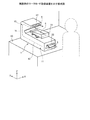
図1は、実施例のマークカード取扱装置を示す模式図である。図2は、実施例のマークカード取扱装置を示す透視側面図である。図3は、実施例のマークカード取扱装置を示す平面図である。
(Configuration of mark card handling equipment)
FIG. 1 is a schematic diagram illustrating a mark card handling apparatus according to an embodiment. FIG. 2 is a perspective side view showing the mark card handling device of the embodiment. FIG. 3 is a plan view showing the mark card handling device of the embodiment.

図1に示すように、実施例のマークカード取扱装置1は、例えば、机上等に載置した状態のように、マークカード取扱装置1の奥行方向に対して制限された環境での使用に適している。マークカード取扱装置1において、机上等の載置面10上にマークカード取扱装置1を載置した状態で、マークカード取扱装置1においてマークカード5を搬送する搬送方向をY方向とし、搬送方向に直交し、かつ載置面10に平行な方向をX方向とする。また、マークカード取扱装置1において、挿入されて搬送されるマークカード5の厚み方向(マークカード取扱装置1の高さ方向)をZ方向とする。   As shown in FIG. 1, the mark card handling device 1 of the embodiment is suitable for use in an environment restricted in the depth direction of the mark card handling device 1, for example, in a state of being placed on a desk or the like. ing. In the mark card handling device 1, in the state where the mark card handling device 1 is placed on the placement surface 10 such as a desk, the transport direction in which the mark card 5 is transported in the mark card handling device 1 is defined as the Y direction. A direction perpendicular to and parallel to the placement surface 10 is defined as an X direction. In the mark card handling device 1, the thickness direction of the mark card 5 inserted and conveyed (the height direction of the mark card handling device 1) is defined as the Z direction.

図2及び図3に示すように、実施例のマークカード取扱装置1は、挿入されたマークカード5を一方向に搬送する搬送路12を構成する搬送機構11と、搬送機構11によって搬送されるマークカード5の表面(おもて面)側のマーク箇所を読み取る第1の読取り部13と、マークカード5の裏面側のマーク箇所を読み取る第2の読取り部14と、を備える。また、マークカード取扱装置1は、搬送機構11によって搬送されたマークカード5を排出する排出路16を構成する排出機構15と、搬送機構11、第1の読取り部13及び第2の読取り部14、排出機構15をそれぞれ制御する制御部18と、を備える。   As shown in FIGS. 2 and 3, the mark card handling device 1 of the embodiment is transported by a transport mechanism 11 that constitutes a transport path 12 that transports the inserted mark card 5 in one direction, and the transport mechanism 11. A first reading unit 13 that reads a mark portion on the front surface (front surface) side of the mark card 5 and a second reading unit 14 that reads a mark portion on the back side of the mark card 5 are provided. Further, the mark card handling device 1 includes a discharge mechanism 15 that constitutes a discharge path 16 for discharging the mark card 5 conveyed by the conveyance mechanism 11, a conveyance mechanism 11, a first reading unit 13, and a second reading unit 14. , And a control unit 18 for controlling the discharge mechanism 15.

マークカード5としては、矩形状に形成されており、短辺の長さが82.5mm程度、長辺の長さが例えば、149.3mm程度、178mm程度、201mm程度である異なる3種類のマークカード5が使用される。実施例のマークカード取扱装置1は、例えば149mm程度から201mm程度までの複数種類のマークカード5を読み取るために用いられる。なお、紙葉類としては、マークカード5に限定されるものではない。本願に係る紙葉類取扱装置としては、マークカード5に加えて各種の投票券、宝くじを取り扱う取扱装置として構成されてもよい。また、紙葉類としては、紙幣が適用されてもよい。   The mark card 5 is formed in a rectangular shape and has three different types of marks having a short side length of about 82.5 mm and a long side length of, for example, about 149.3 mm, about 178 mm, and about 201 mm. Card 5 is used. The mark card handling device 1 of the embodiment is used for reading a plurality of types of mark cards 5 from about 149 mm to about 201 mm, for example. The paper sheets are not limited to the mark card 5. The paper sheet handling apparatus according to the present application may be configured as a handling apparatus that handles various voting tickets and lotteries in addition to the mark card 5. Moreover, a banknote may be applied as paper sheets.

(搬送機構の構成)
図1、図2及び図3に示すように、搬送機構11は、マークカード5が挿入される挿入口22を有するトレイ部材21と、挿入口22から挿入されたマークカード5を装置内部へ取り込む取込みローラ24と、取込みローラ24を駆動する取込み機構25と、を有する。
(Configuration of transport mechanism)
As shown in FIGS. 1, 2, and 3, the transport mechanism 11 takes the tray member 21 having the insertion port 22 into which the mark card 5 is inserted and the mark card 5 inserted from the insertion port 22 into the apparatus. The take-in roller 24 and the take-in mechanism 25 that drives the take-in roller 24 are provided.

トレイ部材21は、マークカード取扱装置1の前面に取り付けられている。トレイ部材21は、複数枚のマークカード5が重ねられた束を積載可能な積載部21aを有する。挿入口22は、X方向に延びるスリット状に形成されている。マークカード5は、搬送路12に対して、挿入口22から長辺方向に沿って挿入される。   The tray member 21 is attached to the front surface of the mark card handling device 1. The tray member 21 has a stacking portion 21a that can stack a bundle in which a plurality of mark cards 5 are stacked. The insertion port 22 is formed in a slit shape extending in the X direction. The mark card 5 is inserted into the transport path 12 from the insertion port 22 along the long side direction.

図3に示すように、取込み機構25は、取込みローラ24を支持する回転軸26と、回転軸26を回転させる駆動モータ27と、駆動モータ27の駆動力を回転軸26に伝える駆動ベルト28と、を有する。   As shown in FIG. 3, the take-in mechanism 25 includes a rotary shaft 26 that supports the take-in roller 24, a drive motor 27 that rotates the rotary shaft 26, and a drive belt 28 that transmits the driving force of the drive motor 27 to the rotary shaft 26. Have.

搬送路12は、挿入口22から、搬送方向が一方向(Y方向)に沿って直線状に延びており、排出路16に連続して設けられている。搬送路12は、取込みローラ24によって取り込まれたマークカード5を、搬送路12に沿って搬送する複数の搬送ローラ群30を有する。搬送路12は、複数の搬送ローラ群30によってマークカード5を長辺方向に沿って搬送する。本実施例における複数の搬送ローラ群30は、第1の搬送ローラ群30A、第2の搬送ローラ群30B、第3の搬送ローラ群30C、第4の搬送ローラ群30D及び第5の搬送ローラ群30Eを含む。   The conveyance path 12 extends from the insertion port 22 in a straight line in the conveyance direction along one direction (Y direction), and is provided continuously to the discharge path 16. The conveyance path 12 includes a plurality of conveyance roller groups 30 that convey the mark card 5 taken in by the take-in roller 24 along the conveyance path 12. The conveyance path 12 conveys the mark card 5 along the long side direction by a plurality of conveyance roller groups 30. In the present embodiment, the plurality of transport roller groups 30 include a first transport roller group 30A, a second transport roller group 30B, a third transport roller group 30C, a fourth transport roller group 30D, and a fifth transport roller group. 30E included.

第1の搬送ローラ群30Aないし第5の搬送ローラ群30Eは、搬送路12を間に挟んで互いに対向して配置された複数の搬送ローラ31及び複数のピンチローラ32を有する。複数の搬送ローラ31は、搬送路12の下方に配置された回転軸33に支持されている。複数のピンチローラ32は、搬送路12の上方に配置された回転軸34に支持されている。   The first conveyance roller group 30A to the fifth conveyance roller group 30E include a plurality of conveyance rollers 31 and a plurality of pinch rollers 32 that are arranged to face each other with the conveyance path 12 therebetween. The plurality of transport rollers 31 are supported by a rotating shaft 33 disposed below the transport path 12. The plurality of pinch rollers 32 are supported by a rotating shaft 34 disposed above the conveyance path 12.

第1の搬送ローラ群30Aは、取込みローラ24の下流に配置されている。第2の搬送ローラ群30Bは、取込みローラ24と、第1の読取り部13との間に配置されている。第3の搬送ローラ30Cは、第1の読取り部13と第2の読取り部14との間に配置されている。第4の搬送ローラ群30Dは、第2の読取り部14の下流側に第2の読取り部14に隣接して配置されている。第5の搬送ローラ群30Eは、搬送路12と排出路16との連結位置近傍の上流に配置されている。   The first transport roller group 30 </ b> A is disposed downstream of the take-in roller 24. The second transport roller group 30 </ b> B is disposed between the take-in roller 24 and the first reading unit 13. The third transport roller 30 </ b> C is disposed between the first reading unit 13 and the second reading unit 14. The fourth transport roller group 30 </ b> D is disposed adjacent to the second reading unit 14 on the downstream side of the second reading unit 14. The fifth transport roller group 30 </ b> E is disposed upstream in the vicinity of the connection position between the transport path 12 and the discharge path 16.

また、搬送機構11は、第1の搬送ローラ群30Aないし第5の搬送ローラ群30Eの各搬送ローラ31の回転軸33を駆動する搬送用の駆動機構36を有する。搬送用の駆動機構36は、回転軸33を回転させる駆動モータ37と、駆動モータ37の駆動力を回転軸33に伝える駆動ベルト38と、を有する。第1の搬送ローラ群30Aないし第5の搬送ローラ群30Eは、搬送用の駆動機構36によって、それぞれ等しい速度で回転される。   Further, the transport mechanism 11 has a transport drive mechanism 36 that drives the rotation shaft 33 of each transport roller 31 of the first transport roller group 30A to the fifth transport roller group 30E. The transport drive mechanism 36 includes a drive motor 37 that rotates the rotary shaft 33, and a drive belt 38 that transmits the drive force of the drive motor 37 to the rotary shaft 33. The first transport roller group 30A to the fifth transport roller group 30E are rotated at equal speeds by the transport drive mechanism 36, respectively.

図4は、実施例のマークカード取扱装置1の搬送路12を開いた状態を示す透視側面図である。また、マークカード取扱装置1は、図2及び図4に示すように、マークカード5が搬送路12内に詰まった場合(以下、ジャムと称する)等に搬送路12のメンテナンス作業を行うために、搬送路12に沿って分離可能に構成されている。実施例のマークカード取扱装置1は、下側シャーシ41と、下側シャーシ41に対して回動される第1の上側シャーシ43及び第2の上側シャーシ44と、を有する。第1の開閉部材としての第1の上側シャーシ43は、搬送路12における挿入口22側(図面の紙面上における搬送路12の右側)を開閉可能に設けられている。第2の開閉部材としての第2の上側シャーシ44は、搬送路12における排出路16側(図面の紙面上における搬送路12の左側)を開閉可能に設けられている。   FIG. 4 is a perspective side view showing a state in which the conveyance path 12 of the mark card handling apparatus 1 of the embodiment is opened. Further, as shown in FIGS. 2 and 4, the mark card handling device 1 performs maintenance work on the transport path 12 when the mark card 5 is jammed in the transport path 12 (hereinafter referred to as jam). , And can be separated along the transport path 12. The mark card handling apparatus 1 according to the embodiment includes a lower chassis 41, and a first upper chassis 43 and a second upper chassis 44 that are rotated with respect to the lower chassis 41. The first upper chassis 43 serving as a first opening / closing member is provided so as to be able to open and close the insertion port 22 side in the transport path 12 (the right side of the transport path 12 on the drawing sheet). The second upper chassis 44 as the second opening / closing member is provided so as to be able to open and close the discharge path 16 side (the left side of the transport path 12 on the paper surface of the drawing) in the transport path 12.

下側シャーシ41には、第1の搬送ローラ群30Aないし第5の搬送ローラ群30Eの各搬送ローラ31が設けられている。第1の上側シャーシ43には、第1の搬送ローラ群30Aのピンチローラ32が設けられている。第1の上側シャーシ43は、下側シャーシ41に設けられた回動軸46を介して、下側シャーシ41に対して回動可能に支持されている。第2の上側シャーシ44には、第2の搬送ローラ群30Bないし第5の搬送ローラ30Eの各ピンチローラ32が設けられている。第2の上側シャーシ44は、下側シャーシ41に設けられた図示しない回動軸を介して、下側シャーシ41に対して回動可能に支持されている。   The lower chassis 41 is provided with the respective transport rollers 31 of the first transport roller group 30A to the fifth transport roller group 30E. The first upper chassis 43 is provided with the pinch rollers 32 of the first transport roller group 30A. The first upper chassis 43 is supported so as to be rotatable with respect to the lower chassis 41 via a rotation shaft 46 provided in the lower chassis 41. The second upper chassis 44 is provided with the respective pinch rollers 32 of the second transport roller group 30B to the fifth transport roller 30E. The second upper chassis 44 is supported so as to be rotatable with respect to the lower chassis 41 via a rotation shaft (not shown) provided in the lower chassis 41.

また、第2の上側シャーシ44には、図4に示すように、第2の上側シャーシ44を支えるための支軸48が設けられている。第2の上側シャーシ44は、下側シャーシ41に対して回動されて搬送路12を開いたときに、回動軸46まわりに回動されて搬送路12を開いた第1の上側シャーシ43によって、支軸48が支えられる。これにより、第2の上側シャーシ44は、搬送路12を開いた姿勢で保たれ、搬送路12のメンテナンス作業をスムースに行うことが可能となる。   Further, as shown in FIG. 4, the second upper chassis 44 is provided with a support shaft 48 for supporting the second upper chassis 44. When the second upper chassis 44 is rotated with respect to the lower chassis 41 to open the conveyance path 12, the second upper chassis 43 is rotated around the rotation shaft 46 to open the conveyance path 12. Thus, the support shaft 48 is supported. As a result, the second upper chassis 44 is maintained in the posture in which the transport path 12 is opened, and the maintenance work of the transport path 12 can be performed smoothly.

(第1の読取り部及び第2の読取り部の構成)
マークカード取扱装置1の第1の読取り部13及び第2の読取り部14は、マークカード5の画像を読み取るイメージセンサ(ラインセンサ)を有する。第1の読取り部13は、搬送路12の上方に、搬送路12の幅方向(X方向)に沿って配置されている。第2の読取り部14は、搬送路12の下方に、搬送路12の幅方向に沿って配置されている。また、第1の読取り部13及び第2の読取り部14は、制御部18と接続されており、マークカード5の読取結果を制御部18へ送信する。
(Configuration of first reading unit and second reading unit)
The first reading unit 13 and the second reading unit 14 of the mark card handling device 1 have an image sensor (line sensor) that reads an image of the mark card 5. The first reading unit 13 is disposed above the transport path 12 along the width direction (X direction) of the transport path 12. The second reading unit 14 is disposed below the transport path 12 along the width direction of the transport path 12. Further, the first reading unit 13 and the second reading unit 14 are connected to the control unit 18 and transmit the reading result of the mark card 5 to the control unit 18.

また、マークカード取扱装置1の搬送路12には、搬送路12に沿って搬送されるマークカード5を検知する複数の位置センサ50を備える。位置センサ50は、検知光を発する発光部51と、発光部51が発した検知光を受光する受光部52と、を有しており、マークカード5が検知光を遮る状態によってマークカード5の通過を検知する。本実施例における複数の位置センサ50は、搬送路12に沿って所定の位置に配置された第1の位置センサ50A、第2の位置センサ50B、第3の位置センサ50C、第4の位置センサ50D、第5の位置センサ50E及び第6の位置センサ50Fを含む。   The conveyance path 12 of the mark card handling apparatus 1 includes a plurality of position sensors 50 that detect the mark card 5 conveyed along the conveyance path 12. The position sensor 50 includes a light emitting unit 51 that emits detection light, and a light receiving unit 52 that receives the detection light emitted from the light emitting unit 51. The position of the mark card 5 depends on the state of the mark card 5 blocking the detection light. Detect passage. In the present embodiment, the plurality of position sensors 50 include a first position sensor 50A, a second position sensor 50B, a third position sensor 50C, and a fourth position sensor arranged at predetermined positions along the conveyance path 12. 50D, the 5th position sensor 50E, and the 6th position sensor 50F are included.

図2に示すように、第1の位置センサ50Aは、挿入口22の近傍に配置されており、挿入口22から挿入されたマークカード5を検知する。第2の位置センサ50Bは、取込みローラ24がマークカード3を取込み始める位置に配置されており、取込みローラ24へ進入するマークカード5を検知する。第3の位置センサ50Cは、第1の搬送ローラ群30Aに対して搬送方向の下流側における第1の搬送ローラ群30Aの近傍に配置されており、第1の搬送ローラ群30Aを通過したマークカード5を検知する。   As shown in FIG. 2, the first position sensor 50 </ b> A is disposed in the vicinity of the insertion slot 22 and detects the mark card 5 inserted from the insertion slot 22. The second position sensor 50 </ b> B is disposed at a position where the take-in roller 24 starts taking in the mark card 3, and detects the mark card 5 entering the take-in roller 24. The third position sensor 50C is arranged in the vicinity of the first conveyance roller group 30A on the downstream side in the conveyance direction with respect to the first conveyance roller group 30A, and the mark that has passed through the first conveyance roller group 30A. Card 5 is detected.

第4の位置センサ50Dは、第2の搬送ローラ群30Bと第1の読取り部13との間における第2の搬送ローラ群30Bの近傍に配置されており、第1の読取り部13へ進入するマークカード5を検知する。第5の位置センサ50Eは、第4の搬送ローラ群30Dの下流側における第4の搬送ローラ群30Dの近傍に配置されており、第2の読取り部14を通って第4の搬送ローラ群30Dを通過したマークカード5を検知する。第6の位置センサ50Fは、第5の搬送ローラ群30Eの近傍に配置されており、第5の搬送ローラ群30Eへ進入するマークカード5を検知する。   The fourth position sensor 50 </ b> D is disposed in the vicinity of the second conveyance roller group 30 </ b> B between the second conveyance roller group 30 </ b> B and the first reading unit 13, and enters the first reading unit 13. The mark card 5 is detected. The fifth position sensor 50E is disposed in the vicinity of the fourth conveyance roller group 30D on the downstream side of the fourth conveyance roller group 30D, passes through the second reading unit 14, and is disposed in the fourth conveyance roller group 30D. The mark card 5 that has passed through is detected. The sixth position sensor 50F is arranged in the vicinity of the fifth transport roller group 30E and detects the mark card 5 entering the fifth transport roller group 30E.

また、第2の読取り部14の下流には、第4の搬送ローラ群30Dの搬送ローラ31間に、搬送路12を搬送されるマークカード5の厚みを検知する厚みセンサ54が配置されている。厚みセンサ54は、図示しないが、マークカード5に接する検知ローラと、マークカード5の厚みに応じて移動する変位部材と、変位部材の変位量を検知する検知部と、を有する。   Further, a thickness sensor 54 that detects the thickness of the mark card 5 that is transported through the transport path 12 is disposed between the transport rollers 31 of the fourth transport roller group 30D downstream of the second reading unit 14. . Although not shown, the thickness sensor 54 includes a detection roller that is in contact with the mark card 5, a displacement member that moves according to the thickness of the mark card 5, and a detection unit that detects the amount of displacement of the displacement member.

(排出機構の構成)
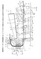
図2に示すように、排出機構15の排出路16は、搬送路12によって搬送されたマークカード5を排出する排出口17を有する。排出路16は、第2の読取り部14を通過したマークカード5を上方へ送ると共に、搬送路12の搬送方向(一方向)と逆方向へ送るU字状に形成されている。
(Configuration of discharge mechanism)
As shown in FIG. 2, the discharge path 16 of the discharge mechanism 15 has a discharge port 17 through which the mark card 5 conveyed by the conveyance path 12 is discharged. The discharge path 16 is formed in a U-shape that sends the mark card 5 that has passed through the second reading unit 14 upward and sends it in the direction opposite to the conveyance direction (one direction) of the conveyance path 12.

排出路16は、搬送路12から送られたマークカード5の搬送方向を上方へ曲げる第1の湾曲路16aと、第1の湾曲路16aを通ったマークカード5を上方へ送る直線路16bと、直線路16bを通ったマークカード5の搬送方向を一方向と逆方向へ曲げる第2の湾曲路16cと、を有する。   The discharge path 16 includes a first curved path 16a that bends the transport direction of the mark card 5 sent from the transport path 12, and a straight path 16b that feeds the mark card 5 that has passed through the first curved path 16a upward. And a second curved path 16c that bends the conveying direction of the mark card 5 through the straight path 16b in a direction opposite to the one direction.

また、第1の湾曲路16aは、第1の湾曲路16aに沿って送られるマークカード5の厚み方向(Z方向)において、図2に示すように、搬送路12側の一端の間隔Aが搬送路12の間隔Cよりも広げられている。また、第1の湾曲路16aは、搬送路12側の一端の間隔Aが、直線路16b側の間隔Bへ向かって徐々に小さくなっている。このように、第1の湾曲路16aは、マークカード5の送り方向において、直線路16bに向かって間隔が狭くされたテーパ状に形成されている。排出路16は、第1の湾曲路16aの間隔Aが搬送路12よりも広げられることで、搬送路12から排出路16内へ進入するマークカード5が第1の湾曲路16aに沿ってスムースに導かれる。これにより、第1の湾曲路16aでマークカード5にジャムが発生することが抑えられる。   Further, in the first curved path 16a, as shown in FIG. 2, in the thickness direction (Z direction) of the mark card 5 sent along the first curved path 16a, an interval A at one end on the conveying path 12 side is set. It is wider than the interval C of the conveyance path 12. In the first curved path 16a, the interval A at one end on the conveyance path 12 side gradually decreases toward the interval B on the straight path 16b side. Thus, the 1st curved path 16a is formed in the taper shape by which the space | interval was narrowed toward the straight path 16b in the feed direction of the mark card | curd 5. FIG. In the discharge path 16, the interval A between the first curved paths 16 a is wider than the transport path 12, so that the mark card 5 entering the discharge path 16 from the transport path 12 is smoothly along the first curved path 16 a. Led to. As a result, the occurrence of jam in the mark card 5 on the first curved path 16a is suppressed.

排出機構15は、搬送路12の第5の搬送ローラ群30E等によって搬送されたマークカード5を、排出路16に沿って送る第1の排出ローラ群60A及び第2の排出ローラ群60Bを有する。第1の排出ローラ群60A及び第2の排出ローラ群60Bは、排出路16を間に挟んで互いに対向して配置された複数の排出ローラ61及び複数のピンチローラ62を有する。   The discharge mechanism 15 includes a first discharge roller group 60A and a second discharge roller group 60B that send the mark card 5 conveyed by the fifth conveyance roller group 30E and the like of the conveyance path 12 along the discharge path 16. . The first discharge roller group 60 </ b> A and the second discharge roller group 60 </ b> B include a plurality of discharge rollers 61 and a plurality of pinch rollers 62 that are disposed to face each other with the discharge path 16 interposed therebetween.

第1のローラとしての第1の排出ローラ群60Aの排出ローラ61は、排出路16の第1の湾曲路16aにおける搬送路12側の一端と排出口17との間の中途位置にある直線路16bに配置されている。第1の排出ローラ群60Aの排出ローラ61は、排出路16の直線路16bにおける装置前方側に設けられた回転軸63に支持されている。本実施例は、第1のローラとしての排出ローラ61を、排出路16の直線路16bに配置する構成に限定するものではない。第1のローラとしての排出ローラ61は、排出条件等の必要に応じて、第1の湾曲路16aまたは第2の湾曲路16cにおける所望の位置に配置されてもよい。   The discharge roller 61 of the first discharge roller group 60 </ b> A as the first roller is a straight path between the one end of the first curved path 16 a of the discharge path 16 on the conveyance path 12 side and the discharge port 17. 16b. The discharge roller 61 of the first discharge roller group 60 </ b> A is supported by a rotating shaft 63 provided on the front side of the apparatus in the straight path 16 b of the discharge path 16. In the present embodiment, the discharge roller 61 as the first roller is not limited to the configuration in which the discharge roller 61 is disposed on the straight path 16b of the discharge path 16. The discharge roller 61 as the first roller may be disposed at a desired position in the first curved path 16a or the second curved path 16c, depending on the discharge conditions and the like.

第2のローラとしての第2の排出ローラ群60Bの排出ローラ61は、排出口17に配置されている。第2の排出ローラ群60Bの排出ローラ61は、排出口17に配置された回転軸63に支持されている。本実施例では、第2の排出ローラ群60Bが排出口17に配置されたが、排出口17の近傍に配置されてもよく、排出条件等の必要に応じて排出口17から所定の距離だけ離間して配置されもよい。   The discharge roller 61 of the second discharge roller group 60 </ b> B as the second roller is disposed in the discharge port 17. The discharge roller 61 of the second discharge roller group 60 </ b> B is supported by a rotating shaft 63 disposed at the discharge port 17. In the present embodiment, the second discharge roller group 60B is disposed at the discharge port 17. However, it may be disposed near the discharge port 17, and only a predetermined distance from the discharge port 17 according to the discharge conditions and the like. They may be spaced apart.

ピンチローラ62は、第1及び第2の排出ローラ群60A、60Bの排出ローラ61に対向して配置されており、排出路16を挟んで回転軸63に対向して配置された回転軸64に支持されている。また、ピンチローラ62の回転軸64は、軸受け部材66に支持されている。軸受け部材66は、搖動軸67まわりに搖動可能に支持されており、コイルバネ等の付勢部材68の付勢力によって、排出ローラ61に対してピンチローラ62を所定の圧接力で押圧している。   The pinch roller 62 is disposed to face the discharge roller 61 of the first and second discharge roller groups 60A and 60B, and is connected to the rotation shaft 64 that is disposed to face the rotation shaft 63 across the discharge path 16. It is supported. The rotating shaft 64 of the pinch roller 62 is supported by a bearing member 66. The bearing member 66 is supported so as to be swingable around the swing shaft 67, and presses the pinch roller 62 against the discharge roller 61 with a predetermined pressure contact force by a biasing force of a biasing member 68 such as a coil spring.

排出機構15は、第1の排出ローラ群60A及び第2の排出ローラ群60Bの各排出ローラ61の回転軸63を駆動する排出用の駆動機構70を有する。排出用の駆動機構70は、上述した搬送用の駆動機構36の駆動モータ37によって回転される駆動ギア71と、駆動ギア71によって駆動されるローラギア72と、を有する。また、排出用の駆動機構70は、駆動モータ37の駆動力を駆動ギア71へ伝える第1の駆動ベルト73と、ローラギア72の駆動力を第2の排出ローラ群60Bの回転軸63へ伝える第2の駆動ベルト74と、駆動ギア71を支持する回転軸75と、を有する。   The discharge mechanism 15 includes a drive mechanism 70 for discharge that drives the rotation shaft 63 of each discharge roller 61 of the first discharge roller group 60A and the second discharge roller group 60B. The discharge drive mechanism 70 includes a drive gear 71 rotated by the drive motor 37 of the transport drive mechanism 36 described above, and a roller gear 72 driven by the drive gear 71. The discharge drive mechanism 70 also transmits a first drive belt 73 that transmits the drive force of the drive motor 37 to the drive gear 71, and a first drive belt 73 that transmits the drive force of the roller gear 72 to the rotation shaft 63 of the second discharge roller group 60B. Two drive belts 74 and a rotating shaft 75 that supports the drive gear 71.

第1の排出ローラ群60A及び第2の排出ローラ群60Bの各排出ローラ61は、単一の駆動源である駆動モータ37によってそれぞれ駆動されるので、排出用の駆動機構70全体が簡素化される。また、排出機構15は、排出路16の中途位置である直線路16bと排出口17とにのみに配置された第1の排出ローラ群60A及び第2の排出ローラ群60Bによってマークカード5を排出する。つまり、排出路16の送り方向における2箇所のみに各排出ローラ群60A、60Bを配置することで、マークカード5を送るための排出ローラ群の配置位置が必要最小限に抑えられるので、排出路16及び排出機構15全体の小型化が図られる。   Since each discharge roller 61 of the first discharge roller group 60A and the second discharge roller group 60B is driven by a drive motor 37 that is a single drive source, the entire discharge drive mechanism 70 is simplified. The Further, the discharge mechanism 15 discharges the mark card 5 by the first discharge roller group 60A and the second discharge roller group 60B arranged only in the straight path 16b and the discharge port 17 which are in the middle of the discharge path 16. To do. That is, by disposing the discharge roller groups 60A and 60B only at two places in the feed direction of the discharge path 16, the arrangement position of the discharge roller group for feeding the mark card 5 can be suppressed to the minimum necessary. 16 and the discharge mechanism 15 as a whole can be reduced in size.

以上のように構成された排出用の駆動機構70により、排出路16の第1及び第2の排出ローラ群60A、60Bの排出ローラ61と、搬送路12の第1ないし第5の搬送ローラ群30A〜30Eの搬送ローラ31とは、それぞれ等しい速度で駆動される。このため、搬送路12及び排出路16に沿ってマークカード5が均一の速度で送られるので、搬送路12内及び排出路16内でマークカード5のジャムが生じることが抑えられる。   By the discharge driving mechanism 70 configured as described above, the discharge rollers 61 of the first and second discharge roller groups 60A and 60B of the discharge path 16 and the first to fifth transfer roller groups of the transfer path 12 are provided. The conveyance rollers 31 of 30A to 30E are driven at the same speed. For this reason, since the mark card 5 is sent along the transport path 12 and the discharge path 16 at a uniform speed, it is possible to suppress the jam of the mark card 5 in the transport path 12 and the discharge path 16.

なお、排出用の駆動機構70は、上述した構成に限定されるものではなく、駆動モータ37によって駆動される図示しない駆動力伝達部材を介して、第1の排出ローラ群60A及び第2の排出ローラ群60Bの各排出ローラ61が駆動されるように構成されてもよい。また、第1の排出ローラ群60A及び第2の排出ローラ群60Bの各排出ローラ61は、駆動モータ37とは別に設けられた図示しない共通の駆動モータによって駆動されるように構成されてもよい。   The discharge drive mechanism 70 is not limited to the above-described configuration, and the first discharge roller group 60 </ b> A and the second discharge are connected via a driving force transmission member (not shown) driven by the drive motor 37. The discharge rollers 61 of the roller group 60B may be driven. The discharge rollers 61 of the first discharge roller group 60 </ b> A and the second discharge roller group 60 </ b> B may be configured to be driven by a common drive motor (not shown) provided separately from the drive motor 37. .

また、マークカード取扱装置1の上部には、排出路16の排出口17から排出されたマークカード5が進入して収容される収容部材としてのスタッカ77が設けられている。スタッカ77は、マークカード5が積載される集積面77aを有しており、集積面77aが、水平面(X−Y平面)に対して所定の傾斜角で傾斜された姿勢で、上述した第2の上側シャーシ44上に固定されている。集積面77aは、水平面に対する傾斜角が例えば15度程度で傾斜されており、周壁によって包囲されている。   In addition, a stacker 77 is provided at the upper portion of the mark card handling device 1 as an accommodation member for accommodating the mark card 5 discharged from the discharge port 17 of the discharge path 16 and receiving it. The stacker 77 has an accumulation surface 77a on which the mark card 5 is stacked. The accumulation surface 77a is inclined at a predetermined inclination angle with respect to a horizontal plane (XY plane), and the second stack described above. The upper chassis 44 is fixed to the upper chassis 44. The accumulation surface 77a is inclined at an inclination angle of, for example, about 15 degrees with respect to the horizontal plane, and is surrounded by the peripheral wall.

スタッカ77は、例えば、排出口17から排出されるマークカード5の排出速度、排出口17から排出される方向(角度)や、スタッカ77の集積面77aの傾斜角、集積面77aの大きさ等が適正に設定されており、排出口17から排出されたマークカード5が集積面77a上に集積される。スタッカ77は、図4に示すように、第2の上側シャーシ44の回動量及び集積面77aの傾斜角が適正に設定されることで、第2の上側シャーシ44が上方へ回動された場合であっても集積面77aが適正な傾斜角に保たれている。これにより、集積面77a上に載置されたマークカード5がスタッカ77内から脱落することを抑えられている。また、スタッカ77は、第2の上側シャーシ44が上方へ回動された姿勢においても、排出路16を構成する装置本体と干渉することが抑えられている。   The stacker 77 is, for example, the discharge speed of the mark card 5 discharged from the discharge port 17, the direction (angle) discharged from the discharge port 17, the inclination angle of the stacking surface 77a of the stacker 77, the size of the stacking surface 77a, etc. Is set appropriately, and the mark cards 5 discharged from the discharge port 17 are stacked on the stacking surface 77a. As shown in FIG. 4, the stacker 77 is configured so that the second upper chassis 44 is rotated upward by setting the rotation amount of the second upper chassis 44 and the inclination angle of the stacking surface 77a appropriately. Even so, the accumulation surface 77a is maintained at an appropriate inclination angle. This prevents the mark card 5 placed on the stacking surface 77a from dropping out of the stacker 77. Further, the stacker 77 is prevented from interfering with the apparatus main body constituting the discharge path 16 even in the posture in which the second upper chassis 44 is rotated upward.

(マークカードの取扱動作)
以上のように構成された実施例のマークカード取扱装置1について、マークカード5の取扱動作を説明する。
(Mark card handling)
About the mark card handling apparatus 1 of the Example comprised as mentioned above, the handling operation of the mark card 5 is demonstrated.

図5Aは、実施例のマークカード取扱装置1において、挿入口22からマークカード5が挿入される状態を示す透視側面図である。図5Bは、実施例のマークカード取扱装置1において、第1及び第2の読取り部13、14によってマークカード5が読み取られる状態を示す透視側面図である。図5Cは、実施例のマークカード取扱装置1において、マークカード5が排出路16へ送られる状態を示す透視側面図である。図5Dは、実施例のマークカード取扱装置1において、マークカード5が排出口17から排出される状態を示す透視側面図である。   FIG. 5A is a perspective side view showing a state in which the mark card 5 is inserted from the insertion port 22 in the mark card handling apparatus 1 of the embodiment. FIG. 5B is a perspective side view showing a state in which the mark card 5 is read by the first and second reading units 13 and 14 in the mark card handling apparatus 1 of the embodiment. FIG. 5C is a perspective side view showing a state in which the mark card 5 is sent to the discharge path 16 in the mark card handling apparatus 1 of the embodiment. FIG. 5D is a perspective side view showing a state in which the mark card 5 is discharged from the discharge port 17 in the mark card handling apparatus 1 of the embodiment.

図5Aに示すように、トレイ21の積載面21a上に積載された複数のマークカード5は、取込みローラ24が回転することで挿入口22から1枚ずつ取り込まれる。あるいは、挿入口22から1枚ずつ挿入されたマークカード5は、取込みローラ24が回転することで挿入口22から取り込まれる。取込みローラ24によって取り込まれたマークカード5は、各搬送ローラ群30によって搬送路12に沿って搬送される。   As shown in FIG. 5A, the plurality of mark cards 5 stacked on the stacking surface 21a of the tray 21 are taken in one by one from the insertion slot 22 as the take-in roller 24 rotates. Alternatively, the mark cards 5 inserted one by one from the insertion port 22 are taken from the insertion port 22 as the take-in roller 24 rotates. The mark card 5 taken in by the take-in roller 24 is transported along the transport path 12 by each transport roller group 30.

搬送路12に沿って搬送されたマークカード5は、図5Bに示すように、搬送方向における前端が第1の読取り部13へ進入する。マークカード5は、搬送路12に沿って搬送されながら、第1の読取り部13によって、マークカード5の表面側のマーク箇所が読み取られる。続いて、第1の読取り部13から搬送されたマークカード5は、前端が第2の読取り部14へ進入する。マークカード5は、搬送路12に沿って搬送されながら、第2の読取り部14によって、マークカード5の裏面側のマーク箇所が読み取られる。   As shown in FIG. 5B, the front end of the mark card 5 conveyed along the conveyance path 12 enters the first reading unit 13 as shown in FIG. 5B. While the mark card 5 is conveyed along the conveyance path 12, the mark portion on the front side of the mark card 5 is read by the first reading unit 13. Subsequently, the front end of the mark card 5 conveyed from the first reading unit 13 enters the second reading unit 14. While the mark card 5 is conveyed along the conveyance path 12, the mark portion on the back side of the mark card 5 is read by the second reading unit 14.

図5Cに示すように、マークカード5は、第2の読取り部14によって読み取られながら、マークカード5の前端が排出路16に沿って排出される。例えば、長辺が201mm程度の長さが200mmを超える長尺のマークカード5、及び長辺が149mm程度のマークカード5を使用する場合において、第2の読取り部14で読取り中のマークカード5は、搬送方向における前端側が、U字状の排出路16内に進入している。このように、搬送路12内で読取り中のマークカード5の前端が、排出路16の第1の湾曲路16a内へ進入する程度まで、排出路16をコンパクトに構成することにより、マークカード取扱装置1の奥行方向(Y方向)に対して小型化が図られている。   As shown in FIG. 5C, the front end of the mark card 5 is discharged along the discharge path 16 while being read by the second reading unit 14. For example, when using a long mark card 5 having a long side of about 201 mm and a long side exceeding 200 mm, and a mark card 5 having a long side of about 149 mm, the mark card 5 being read by the second reading unit 14 is used. The front end side in the transport direction enters the U-shaped discharge path 16. Thus, the mark card is handled by making the discharge path 16 compact so that the front end of the mark card 5 being read in the transport path 12 enters the first curved path 16a of the discharge path 16. Miniaturization is achieved with respect to the depth direction (Y direction) of the device 1.

第2の読取り部14を通過したマークカード5は、搬送路12から排出路16の第1の湾曲路16a内へ進入する。第1の湾曲路16aの一端の間隔Aが、搬送路12の間隔Cよりも広くされたことで(図2)、マークカード5が第1の湾曲路16a内へ進入するときに、マークカード5の前端が第1の湾曲路16aに沿ってスムースに送られる。   The mark card 5 that has passed through the second reading unit 14 enters the first curved path 16 a of the discharge path 16 from the transport path 12. When the interval A at one end of the first curved path 16a is made wider than the interval C of the conveying path 12 (FIG. 2), when the mark card 5 enters the first curved path 16a, the mark card The front end of 5 is smoothly fed along the first curved path 16a.

図5Dに示すように、搬送路12から排出路16へ送られたマークカード5は、第1の排出ローラ群60A及び第2の排出ローラ群60Bによって、第1の湾曲路16a、直線路16b及び第2の湾曲路16cに沿って送られる。排出路16に沿って送られたマークカード5は、排出口17から排出されると共に、スタッカ77内に収容される。   As shown in FIG. 5D, the mark card 5 sent from the conveyance path 12 to the discharge path 16 is first curved path 16a and straight path 16b by the first discharge roller group 60A and the second discharge roller group 60B. And along the second curved path 16c. The mark card 5 sent along the discharge path 16 is discharged from the discharge port 17 and accommodated in the stacker 77.

なお、本実施例では、排出口17から排出されたマークカード5がスタッカ77内へ収容されたが、排出動作を限定するものではない。例えば、制御部18によって排出機構15を制御することで、マークカード5を第2の排出ローラ群60Bに一時的に保持させてもよい。マークカード5を第2の排出ローラ群60Bに一時的に保持させることにより、ユーザは、マークカード5を排出路16の排出口17から抜き取ることが可能になる。例えば、制御部18は、第1及び第2の読取り部13、14の読取り結果に応じて排出機構15を制御し、第1及び第2の読取り部13、14によって正常に読み取られた場合のみ、マークカード5をスタッカ77へ収容するように構成されてもよい。この場合、制御部18は、第1及び第2の読取り部13、14で読取りエラーが生じた場合に、マークカード5を、第2の排出ローラ群60Bで一時的に保持させる。これにより、例えば、読取りエラーが生じたマークカード5をスタッカ77内から探すことなく、マークカード取扱装置1から容易に取り出すことが可能になる。   In the present embodiment, the mark card 5 discharged from the discharge port 17 is accommodated in the stacker 77, but the discharge operation is not limited. For example, the control unit 18 may control the discharge mechanism 15 to temporarily hold the mark card 5 in the second discharge roller group 60B. By temporarily holding the mark card 5 on the second discharge roller group 60 </ b> B, the user can remove the mark card 5 from the discharge port 17 of the discharge path 16. For example, the control unit 18 controls the discharge mechanism 15 according to the reading results of the first and second reading units 13 and 14, and only when the reading is normally performed by the first and second reading units 13 and 14. The mark card 5 may be accommodated in the stacker 77. In this case, when a reading error occurs in the first and second reading units 13 and 14, the control unit 18 temporarily holds the mark card 5 by the second discharge roller group 60B. Thereby, for example, the mark card 5 in which the reading error has occurred can be easily taken out from the mark card handling apparatus 1 without searching the stacker 77.

(マークカード取扱方法)
以上のように構成されたマークカード取扱装置1におけるマークカード取扱方法は、挿入口22から挿入されたマークカード5を一方向に沿って搬送路12を搬送し、搬送路12に設けられた第1及び第2の読取り部13、14によってマークカード5を読み取る。また、マークカード取扱方法は、第1及び第2の読取り部13、14を通過したマークカード5を上方へ送ると共に一方向と逆方向へ送ることで、搬送路12によって搬送されたマークカード5を、U字状の排出路16の排出口17から排出する。マークカード取扱方法は、排出路16によってマークカード5を排出するときに、排出路16における搬送路12側の一端と排出口17との間の中途位置に配置された第1の排出ローラ群60Aの排出ローラ61と、排出口17に配置された第2の排出ローラ群60Bの排出ローラ61とを、単一の駆動モータ37で回転する。これにより、中途位置と排出口17のみに配置された第1の排出ローラ群60Aの排出ローラ61及び第2の排出ローラ群60Bの排出ローラ61によってマークカード5を排出する。
(Mark card handling method)
The mark card handling method in the mark card handling apparatus 1 configured as described above is such that the mark card 5 inserted from the insertion port 22 is conveyed along the conveyance path 12 along one direction, and is provided in the conveyance path 12. The mark card 5 is read by the first and second reading units 13 and 14. The mark card handling method is such that the mark card 5 that has passed through the first and second reading units 13 and 14 is sent upward and sent in one direction and in the opposite direction, so that the mark card 5 conveyed by the conveyance path 12 is transferred. Is discharged from the discharge port 17 of the U-shaped discharge path 16. In the mark card handling method, when the mark card 5 is discharged by the discharge path 16, the first discharge roller group 60 </ b> A disposed at a midway position between one end of the discharge path 16 on the conveyance path 12 side and the discharge port 17. The discharge roller 61 and the discharge roller 61 of the second discharge roller group 60 </ b> B disposed at the discharge port 17 are rotated by a single drive motor 37. As a result, the mark card 5 is discharged by the discharge roller 61 of the first discharge roller group 60A and the discharge roller 61 of the second discharge roller group 60B disposed only in the middle position and the discharge port 17.

実施例のマークカード取扱装置1は、第1及び第2の読取り部13、14を通過したマークカード5を上方へ送ると共に搬送路12の搬送方向(一方向)と逆方向へ送るU字状の排出路16を備える。排出路16は、排出路16における中途位置に配置された第1の排出ローラ群60Aの排出ローラ61と、排出口17に配置された第2の排出ローラ群60Bの排出ローラ61と、第1の排出ローラ群60Aの排出ローラ61及び第2の排出ローラ群60Bの排出ローラ61をそれぞれ駆動する単一の駆動モータ37と、を有する。排出路16は、中途位置と排出口17のみに配置された各排出ローラ61によってマークカード5を排出する。これにより、排出路16に沿って配置される複数の排出ローラ群60A、60Bを、共通の駆動モータ37を用いて駆動することによって、排出機構15を小型化することができる。また、排出路16に沿った複数の排出ローラ群の配置位置が必要最小限に抑えられるので、排出機構15を小型化することができる。   The mark card handling device 1 of the embodiment is U-shaped to send the mark card 5 that has passed through the first and second reading units 13 and 14 upward and to send the mark card 5 in the direction opposite to the conveyance direction (one direction) of the conveyance path 12. The discharge path 16 is provided. The discharge path 16 includes a discharge roller 61 of the first discharge roller group 60 </ b> A disposed at an intermediate position in the discharge path 16, a discharge roller 61 of the second discharge roller group 60 </ b> B disposed at the discharge port 17, A single drive motor 37 that drives the discharge roller 61 of the discharge roller group 60A and the discharge roller 61 of the second discharge roller group 60B. The discharge path 16 discharges the mark card 5 by the discharge rollers 61 arranged only at the midway position and the discharge port 17. Accordingly, the discharge mechanism 15 can be reduced in size by driving the plurality of discharge roller groups 60 </ b> A and 60 </ b> B disposed along the discharge path 16 using the common drive motor 37. In addition, since the arrangement positions of the plurality of discharge roller groups along the discharge path 16 can be minimized, the discharge mechanism 15 can be reduced in size.

また、マークカード取扱装置1によれば、例えば、長辺の長さが149mm程度から、201mm程度の長尺のマークカード5を取り扱うことができる。マークカード取扱装置1によれば、上述のような長尺のマークカード5を取り扱うことができると共に、奥行方向(Y方向)に対して小型化することができる。したがって、マークカード取扱装置1は、例えば、周囲が壁で包囲された机上の載置面10に載置して使用する場合等のように、机上の奥行方向に対して制限された環境で使用する場合に適している。   Further, according to the mark card handling apparatus 1, for example, a long mark card 5 having a long side length of about 149 mm to about 201 mm can be handled. According to the mark card handling apparatus 1, the long mark card 5 as described above can be handled, and the size can be reduced with respect to the depth direction (Y direction). Therefore, the mark card handling device 1 is used in an environment restricted with respect to the depth direction on the desk, for example, when it is used by being placed on the desk surface 10 surrounded by a wall. Suitable for you.

また、マークカード取扱装置1が有する第1の排出ローラ群60Aの排出ローラ61は、マークカード5の搬送方向における後端側が第2の読取り部14で読み取られているときに、第1の排出ローラ群60Aの排出ローラ61がマークカード5の前端側を送り可能な位置に配置されている。このように、第2の読取り部14で読取り中のマークカード5の後端が排出路16内に進入する程度まで排出路16をコンパクトに構成することで、マークカード取扱装置1の奥行方向(Y方向)に対して小型化することができる。   Further, the discharge rollers 61 of the first discharge roller group 60 </ b> A included in the mark card handling device 1 are configured to perform the first discharge when the rear end side in the conveyance direction of the mark card 5 is read by the second reading unit 14. The discharge roller 61 of the roller group 60A is arranged at a position where the front end side of the mark card 5 can be fed. In this way, by forming the discharge path 16 compactly to the extent that the rear end of the mark card 5 being read by the second reading unit 14 enters the discharge path 16, the depth direction of the mark card handling device 1 ( The size can be reduced with respect to (Y direction).

また、マークカード取扱装置1が有する排出路16は、マークカード5の搬送方向を上方へ曲げる第1の湾曲路16aと、第1の湾曲路16aを通ったマークカード5を上方へ送る直線路16bと、直線路16bを通ったマークカード5の搬送方向を逆方向へ曲げる第2の湾曲路16cと、を有する。第1の排出ローラ群60Aの排出ローラ61は、直線路16bに配置されている。これにより、第1の排出ローラ群60Aの排出ローラ61は、第1の湾曲路16aから進入するマークカード5を送ると共に、第2の湾曲路16cに沿って排出口17からマークカード5を排出することが可能になる。その結果、排出路16に沿った排出ローラ群の配置位置が必要最小限に抑えられ、排出路16及び排出機構15を小型化することができる。   Further, the discharge path 16 of the mark card handling device 1 includes a first curved path 16a that bends the conveying direction of the mark card 5 upward, and a straight path that sends the mark card 5 that has passed through the first curved path 16a upward. 16b and a second curved path 16c that bends the conveying direction of the mark card 5 that has passed through the straight path 16b in the reverse direction. The discharge rollers 61 of the first discharge roller group 60A are arranged in the straight path 16b. Thereby, the discharge roller 61 of the first discharge roller group 60A sends the mark card 5 entering from the first curved path 16a and discharges the mark card 5 from the discharge port 17 along the second curved path 16c. It becomes possible to do. As a result, the arrangement position of the discharge roller group along the discharge path 16 is minimized, and the discharge path 16 and the discharge mechanism 15 can be downsized.

また、マークカード取扱装置1が有する排出路16の第1の湾曲路16aは、第1の湾曲路16aを送られるマークカード5の厚み方向において、搬送路12側の一端の間隔Aが搬送路12の終端の間隔Cよりも広げられると共に、間隔Aが直線路16b側へ向かって徐々に小さくされている。これにより、搬送路12から排出路16内へ進入するマークカード5が第1の湾曲路16aに沿ってスムースに導かれるので、第1の湾曲路16aでマークカード5のジャムが発生することを抑えられる。   Further, the first curved path 16a of the discharge path 16 included in the mark card handling apparatus 1 is such that the distance A between the one ends on the transport path 12 side in the thickness direction of the mark card 5 fed through the first curved path 16a is the transport path. 12 and the distance A is gradually reduced toward the straight path 16b. As a result, the mark card 5 entering the discharge path 16 from the transport path 12 is smoothly guided along the first curved path 16a, so that the jam of the mark card 5 occurs in the first curved path 16a. It can be suppressed.

また、実施例におけるマークカード取扱装置1は、排出路16の排出口17から排出されたマークカード5が進入して収容されるスタッカ77を備える。これにより、排出路16から排出されたマークカード5をスタッカ77内に集積して収容することが可能になり、マークカード5の取扱時の作業性を高めることができる。   Further, the mark card handling apparatus 1 in the embodiment includes a stacker 77 in which the mark card 5 discharged from the discharge port 17 of the discharge path 16 enters and is stored. As a result, the mark card 5 discharged from the discharge path 16 can be collected and stored in the stacker 77, and the workability at the time of handling the mark card 5 can be improved.

また、実施例におけるマークカード取扱装置1は、搬送路12における挿入口22側を開閉可能に設けられた第1の上側シャーシ43と、搬送路12における排出路16側を開閉可能に設けられた第2の上側シャーシ44と、を備える。第2の上側シャーシ44は、搬送路12を開いた姿勢で、搬送路12を開いた第1の上側シャーシ43によって支持される。これにより、第2の上側シャーシ44を第1の上側シャーシ43によって支持することで、搬送路12のジャム時にメンテナンスを行うときの作業性を高めることが可能になる。また、2つに分割された第1の上側シャーシ43と第2の上側シャーシ44とによって搬送路12が開かれるので、ジャムが発生しやすい搬送路12の挿入口22側を大きく開放することが可能になり、メンテナンスの作業性を高めることができる。   Further, the mark card handling device 1 in the embodiment is provided so that the first upper chassis 43 provided to be able to open and close the insertion port 22 side in the conveyance path 12 and the discharge path 16 side in the conveyance path 12 can be opened and closed. A second upper chassis 44. The second upper chassis 44 is supported by the first upper chassis 43 that opens the transport path 12 in a posture in which the transport path 12 is opened. Thus, by supporting the second upper chassis 44 by the first upper chassis 43, it is possible to improve workability when performing maintenance when the conveyance path 12 is jammed. Further, since the conveyance path 12 is opened by the first upper chassis 43 and the second upper chassis 44 divided into two, it is possible to greatly open the insertion port 22 side of the conveyance path 12 where jamming is likely to occur. This makes it possible to improve the workability of maintenance.

以下、変形例について図面を参照して説明する。変形例において、実施例と同一の構成部材には、便宜上、実施例と同一の符号を付して説明を省略する。変形例は、排出路16から排出されるマークカード5及び投票券を分離して排出する点が、実施例と異なる。   Hereinafter, modified examples will be described with reference to the drawings. In the modification, the same components as those in the embodiment are denoted by the same reference numerals as those in the embodiment, and the description thereof is omitted for the sake of convenience. The modification differs from the embodiment in that the mark card 5 and the voting ticket discharged from the discharge path 16 are separated and discharged.

<変形例>
図6は、変形例のマークカード取扱装置を模式的に示す側面図である。図6に示すように、変形例のマークカード取扱装置2は、挿入口22から挿入されたマークカード5及び投票券を搬送する搬送路12と、搬送路12に沿って搬送されるマークカード5及び投票券を読み取る第1の読取り部13及び第2の読取り部14と、第1及び第2の読取り部13、14を通過したマークカード5及び投票券を外部へ排出する排出路16と、を備える。マークカード取扱装置2において、投票券は、当たり、はずれ等の投票結果の確認が行われる。
<Modification>
FIG. 6 is a side view schematically showing a modified mark card handling apparatus. As shown in FIG. 6, the mark card handling device 2 according to the modified example includes a mark card 5 inserted from the insertion port 22 and a conveyance path 12 that conveys the voting ticket, and a mark card 5 that is conveyed along the conveyance path 12. A first reading unit 13 and a second reading unit 14 that read the voting ticket, a discharge path 16 that discharges the mark card 5 and the voting ticket that have passed through the first and second reading units 13 and 14 to the outside, Is provided. In the mark card handling device 2, the voting ticket is checked for voting results such as hit and miss.

また、変形例のマークカード取扱装置2は、排出するマークカード5及び投票券が分類されてそれぞれ収容される第1のスタッカ81a、第2のスタッカ81b及び第3のスタッカ81cと、排出路16から排出されるマークカード5及び投票券の排出方向、すなわち排出路16の端部の分岐路を切り替える切り換え機構83と、を有する。   Further, the mark card handling device 2 of the modified example includes a first stacker 81a, a second stacker 81b, and a third stacker 81c in which the mark card 5 and voting tickets to be discharged are classified and accommodated, and the discharge path 16. And a switching mechanism 83 that switches the discharge direction of the voting ticket, that is, the branch path at the end of the discharge path 16.

第1、第2及び第3のスタッカ81a、81b、81cは、マークカード取扱装置2の上部に積み重ねて配置されている。切り換え機構83は、制御部18によって制御されることで、移動可能に設けられており、排出路16から排出されるマークカード5及び投票券の位置が切り替えられる。制御部18は、第1及び第2の読取り部13、14の各読取り結果に応じて、切り換え機構83を選択的に制御することで、排出路16から排出されるマークカード5及び投票券を、第1、第2及び第3のスタッカ81a、81b、81cに分類して収容する。   The first, second, and third stackers 81a, 81b, 81c are stacked on the upper part of the mark card handling device 2. The switching mechanism 83 is movably provided by being controlled by the control unit 18, and the positions of the mark card 5 and the voting ticket discharged from the discharge path 16 are switched. The control unit 18 selectively controls the switching mechanism 83 according to the reading results of the first and second reading units 13 and 14, so that the mark card 5 and the voting ticket discharged from the discharge path 16 can be selected. The first, second and third stackers 81a, 81b and 81c are classified and accommodated.

図7は、変形例のマークカード取扱装置2を説明するためのフローチャートである。図7に示すように、マークカード取扱装置2は、第1の読取り部13及び第2の読取り部14によってマークカード5及び投票券を読み取る(ステップS1)。制御部18は、第1の読取り部13及び第2の読取り部14の各読取り結果に基づいて、マークカード5及び投票券が正常に読み取れたか否かを判定する(ステップS2)。ステップS2において、制御部18は、マークカード5及び投票券が正常に読み取れたと判断した場合、第1の読取り部13及び第2の読取り部14の各読取り結果に基づいて、読み取ったものが投票券であるか否かを判定する(ステップS3)。   FIG. 7 is a flowchart for explaining a modified example of the mark card handling apparatus 2. As shown in FIG. 7, the mark card handling apparatus 2 reads the mark card 5 and the voting ticket by the first reading unit 13 and the second reading unit 14 (step S1). The control unit 18 determines whether or not the mark card 5 and the voting ticket are normally read based on the reading results of the first reading unit 13 and the second reading unit 14 (step S2). In step S <b> 2, when the control unit 18 determines that the mark card 5 and the voting ticket have been normally read, the reading unit votes based on the reading results of the first reading unit 13 and the second reading unit 14. It is determined whether it is a ticket (step S3).

ステップS2において、制御部18は、マークカード5及び投票券が正常に読み取れないと判断した場合、切り換え機構83を制御することで、マークカード5及び投票券を第1のスタッカ81aへ排出する(ステップS4)。正常に読み取れないマークカード5には、マーク箇所の記入間違い等を含むマークカード5に加え、マークカード取扱装置2で取扱い対象外となるマークカード5を含む。ステップS3において、制御部18は、投票券ではないと判定した場合、切り換え機構83を制御することで、マークカード5を第2のスタッカ81bへ排出する(ステップS5)。また、ステップS3において、制御部18は、投票券であると判定した場合、切り換え機構83を制御することで、投票券を第3のスタッカ81cへ排出する(ステップS6)。   In step S2, when it is determined that the mark card 5 and the voting ticket cannot be read normally, the control unit 18 controls the switching mechanism 83 to discharge the mark card 5 and the voting ticket to the first stacker 81a ( Step S4). The mark card 5 that cannot be read normally includes the mark card 5 that is not handled by the mark card handling device 2 in addition to the mark card 5 that includes an erroneous entry of the mark location. In step S3, when it determines with the control part 18 not being a voting ticket, it controls the switching mechanism 83 and discharges | emits the mark card 5 to the 2nd stacker 81b (step S5). In step S3, when it is determined that the ticket is a voting ticket, the control unit 18 controls the switching mechanism 83 to discharge the voting ticket to the third stacker 81c (step S6).

上述のように制御することで、制御部18は、読取りエラーが生じたマークカード5及び投票券を第1のスタッカ81a内に収容し、正常に読み取れたマークカード5を第2のスタッカ81b内に収容し、正常に読み取れた投票券を第3のスタッカ81c内に収容する。したがって、マークカード取扱装置2によれば、読取り結果や、マークカード5と投票券とに応じて、第1、第2及び第3のスタッカ81a、81b、81cへ分類して収容することができる。これにより、読み取り後のマークカード5の処理取扱い(正常読み取り、読み取りエラー、取扱い対象外マークカード等)の分類が容易になる。なお、変形例は、スタッカの個数を3つに限定するものではなく、取り扱うマークカード5の種類や、投票券の種類に応じて、更にスタッカを備えて構成されてもよい。   By controlling as described above, the control unit 18 stores the mark card 5 and the voting ticket in which the reading error has occurred in the first stacker 81a, and the normally read mark card 5 in the second stacker 81b. The voting ticket that is normally read and accommodated is accommodated in the third stacker 81c. Therefore, according to the mark card handling device 2, the first, second and third stackers 81a, 81b and 81c can be classified and accommodated according to the reading result and the mark card 5 and the voting ticket. . This facilitates the classification of the handling of the mark card 5 after reading (normal reading, reading error, mark card not to be handled, etc.). In the modified example, the number of stackers is not limited to three, and may be further provided with stackers according to the types of mark cards 5 to be handled and the types of voting tickets.

変形例のマークカード取扱装置2においても、実施例のマークカード取扱装置1と同様に、装置全体の小型化を図ることができる。   Also in the mark card handling device 2 of the modified example, as with the mark card handling device 1 of the embodiment, the overall size of the device can be reduced.

1 マークカード取扱装置
5 マークカード
11 搬送機構
12 搬送路
13 第1の読取り部
14 第2の読取り部
15 排出機構
16 排出路
16a 第1の湾曲路
16b 直線路
16c 第2の湾曲路
17 排出口
18 制御部
22 挿入口
30(30A〜30E) 搬送ローラ群
43 第1の上側シャーシ
44 第2の上側シャーシ
60A 第1の排出ローラ群
60B 第2の排出ローラ群
61 排出ローラ
62 ピンチローラ
77 スタッカ
DESCRIPTION OF SYMBOLS 1 Mark card handling apparatus 5 Mark card 11 Conveyance mechanism 12 Conveyance path 13 1st reading part 14 2nd reading part 15 Discharge mechanism 16 Discharge path 16a 1st curved path 16b Straight path 16c 2nd curved path 17 Discharge port 18 Control Unit 22 Insertion Port 30 (30A-30E) Transport Roller Group 43 First Upper Chassis 44 Second Upper Chassis 60A First Discharge Roller Group 60B Second Discharge Roller Group 61 Discharge Roller 62 Pinch Roller 77 Stacker

Claims (7)

紙葉類が挿入される挿入口を有し、前記挿入口から挿入された前記紙葉類を一方向に沿って搬送する搬送路と、
前記搬送路に設けられ、前記一方向に沿って搬送される前記紙葉類を読み取る読取り部と、
前記搬送路によって搬送された前記紙葉類を外部へ排出する排出口を有し、前記読取り部を通過した前記紙葉類を上方へ送ると共に前記一方向と逆方向へ送るU字状の排出路と、を備え、
前記排出路は、前記排出路における前記搬送路側の一端と前記排出口との間の中途位置に配置された第1のローラと、前記排出口に配置された第2のローラと、前記第1のローラ及び前記第2のローラをそれぞれ駆動する単一の駆動源と、を有し、前記中途位置と前記排出口のみに配置された前記第1のローラ及び前記第2のローラによって前記紙葉類を排出する、紙葉類取扱装置。
A conveyance path that has an insertion slot into which a paper sheet is inserted, and conveys the paper sheet inserted from the insertion slot along one direction;
A reading unit that is provided in the conveyance path and reads the paper sheets conveyed along the one direction;
A U-shaped discharge having a discharge port for discharging the paper sheets conveyed by the conveyance path to the outside, and sending the paper sheets that have passed through the reading unit upward and in the opposite direction to the one direction. Road, and
The discharge path includes a first roller disposed at an intermediate position between one end of the discharge path on the transport path side and the discharge port, a second roller disposed at the discharge port, and the first roller And a single drive source for driving each of the second roller and the paper sheet by the first roller and the second roller disposed only at the midway position and the discharge port. Paper sheet handling device that discharges paper.
前記第1のローラは、前記紙葉類の搬送方向における後端側が前記読取り部によって読み取られているときに、前記第1のローラが前記紙葉類の前端側を送り可能な位置に配置されている、請求項1に記載の紙葉類取扱装置。   The first roller is disposed at a position where the first roller can feed the front end side of the paper sheet when the rear end side in the conveyance direction of the paper sheet is read by the reading unit. The paper sheet handling apparatus according to claim 1. 前記排出路は、前記搬送路に連結されて前記紙葉類の搬送方向を上方へ曲げる第1の湾曲路と、前記第1の湾曲路を通った前記紙葉類を上方へ送る直線路と、前記直線路を通った前記紙葉類の搬送方向を前記逆方向へ曲げる第2の湾曲路と、を有し、
前記第1のローラは、前記直線路に配置されている、請求項1または2に記載の紙葉類取扱装置。
The discharge path is connected to the transport path and bends the transport direction of the paper sheets upward, and a straight path that sends the paper sheets passing through the first curved path upwards A second curved path that bends the conveying direction of the paper sheets passing through the straight path in the opposite direction;
The paper sheet handling apparatus according to claim 1, wherein the first roller is disposed in the straight path.
前記排出路の前記第1の湾曲路は、前記第1の湾曲路に沿って送られる前記紙葉類の厚み方向において、前記搬送路側の一端の間隔が前記搬送路よりも広げられると共に、前記間隔が前記直線路側へ向かって徐々に小さくなるテーパ状に形成されている、請求項3に記載の紙葉類取扱装置。   In the thickness direction of the paper sheet fed along the first curved path, the first curved path of the discharge path is wider than one end of the transport path side than the transport path, and The paper sheet handling apparatus according to claim 3, wherein the paper sheet handling device is formed in a tapered shape in which the interval gradually decreases toward the straight road. 前記排出路の前記排出口から排出された前記紙葉類が進入して収容される収容部材を更に備える、請求項1ないし4のいずれか1項に記載の紙葉類取扱装置。   5. The paper sheet handling apparatus according to claim 1, further comprising a storage member that receives and stores the paper sheet discharged from the discharge port of the discharge path. 前記搬送路における前記挿入口側を開閉可能に設けられた第1の開閉部材と、前記搬送路における前記排出路側を開閉可能に設けられた第2の開閉部材と、を更に備え、
前記第2の開閉部材は、前記搬送路を開いた姿勢で、前記搬送路を開いた前記第1の開閉部材によって支持される、請求項1ないし5のいずれか1項に記載の紙葉類取扱装置。
A first opening / closing member provided to be able to open and close the insertion port side in the transport path; and a second opening / closing member provided to be able to open and close the discharge path side in the transport path,
The paper sheet according to any one of claims 1 to 5, wherein the second opening / closing member is supported by the first opening / closing member that opens the conveyance path in a posture in which the conveyance path is open. Handling equipment.
挿入口から挿入された紙葉類を一方向に沿って搬送路を搬送し、
前記搬送路に設けられた読取り部によって前記紙葉類を読み取り、
前記読取り部を通過した前記紙葉類を上方へ送ると共に一方向と逆方向へ送ることで、前記搬送路によって搬送された前記紙葉類を、U字状の排出路の排出口から排出し、
前記排出路によって前記紙葉類を排出するときに、前記排出路における前記搬送路側の一端と前記排出口との間の中途位置に配置された第1のローラと、前記排出口に配置された第2のローラとを、単一の駆動源で回転することにより、前記中途位置と前記排出口のみに配置された前記第1のローラ及び前記第2のローラによって前記紙葉類を排出する、紙葉類取扱方法。
The paper sheet inserted from the insertion port is transported along the transport path along one direction,
Read the paper sheet by a reading unit provided in the conveyance path,
By sending the paper sheets that have passed through the reading unit upward and in the opposite direction, the paper sheets conveyed by the conveyance path are discharged from the discharge port of the U-shaped discharge path. ,
When discharging the paper sheets by the discharge path, the first roller disposed at a midway position between the one end of the discharge path on the transport path side and the discharge port, and disposed at the discharge port By rotating the second roller with a single drive source, the paper sheets are discharged by the first roller and the second roller disposed only at the midway position and the discharge port, How to handle paper sheets.
JP2016014568A 2016-01-28 2016-01-28 Paper sheets handling device and paper sheets handling method Pending JP2017134669A (en)

Priority Applications (1)

Application Number Priority Date Filing Date Title
JP2016014568A JP2017134669A (en) 2016-01-28 2016-01-28 Paper sheets handling device and paper sheets handling method

Applications Claiming Priority (1)

Application Number Priority Date Filing Date Title
JP2016014568A JP2017134669A (en) 2016-01-28 2016-01-28 Paper sheets handling device and paper sheets handling method

Publications (1)

Publication Number Publication Date
JP2017134669A true JP2017134669A (en) 2017-08-03

Family

ID=59504453

Family Applications (1)

Application Number Title Priority Date Filing Date
JP2016014568A Pending JP2017134669A (en) 2016-01-28 2016-01-28 Paper sheets handling device and paper sheets handling method

Country Status (1)

Country Link
JP (1) JP2017134669A (en)

Citations (7)

* Cited by examiner, † Cited by third party
Publication number Priority date Publication date Assignee Title
JPS5584790U (en) * 1978-12-05 1980-06-11
JPH08123920A (en) * 1994-10-25 1996-05-17 Tamura Electric Works Ltd Card storage structure for magnetic card reader
JP2001222737A (en) * 2000-02-08 2001-08-17 Sanyo Electric Co Ltd Device for discriminating paper money
JP2002260059A (en) * 2001-02-28 2002-09-13 Glory Ltd Paper money dispencing machine
JP2003034058A (en) * 2001-07-25 2003-02-04 Toshiba Corp Passbook processor and method of processing passbook
US20060181018A1 (en) * 2004-11-25 2006-08-17 Oce-Technologies B.V. Sheet handling device
JP2010163248A (en) * 2009-01-15 2010-07-29 Murata Machinery Ltd Relay unit

Patent Citations (7)

* Cited by examiner, † Cited by third party
Publication number Priority date Publication date Assignee Title
JPS5584790U (en) * 1978-12-05 1980-06-11
JPH08123920A (en) * 1994-10-25 1996-05-17 Tamura Electric Works Ltd Card storage structure for magnetic card reader
JP2001222737A (en) * 2000-02-08 2001-08-17 Sanyo Electric Co Ltd Device for discriminating paper money
JP2002260059A (en) * 2001-02-28 2002-09-13 Glory Ltd Paper money dispencing machine
JP2003034058A (en) * 2001-07-25 2003-02-04 Toshiba Corp Passbook processor and method of processing passbook
US20060181018A1 (en) * 2004-11-25 2006-08-17 Oce-Technologies B.V. Sheet handling device
JP2010163248A (en) * 2009-01-15 2010-07-29 Murata Machinery Ltd Relay unit

Similar Documents

Publication Publication Date Title
US8708327B2 (en) Paper sheet handling machine
JP6189124B2 (en) Paper sheet stacking mechanism and paper sheet processing apparatus
WO2016147838A1 (en) Paper sheet transporting device
EP2843631B1 (en) Sheet discriminating device and sheet processing apparatus
EP2724964B1 (en) Sheet sorting/conveying apparatus
WO2018003325A1 (en) Front-back reversing device, paper sheet processor, and front-back reversing method
JP2018140862A (en) Surface and rear surface turnover device and paper sheet processor
JP2017134669A (en) Paper sheets handling device and paper sheets handling method
KR101414754B1 (en) Paper sheet feeding device and paper sheet processing apparatus
US20180033230A1 (en) Paper sheet handling apparatus
CN105492355A (en) Paper sheet stacking device and paper sheet handling device
JP6198929B2 (en) Paper sheet processing equipment
JP4296299B2 (en) Banknote transport device, inter-bank bill transport device and island banknote transport device
JP2007308233A (en) Paper sheet handling apparatus
US8757356B2 (en) Media depository
JPWO2015133392A1 (en) Paper sheet processing equipment
CN112573275B (en) Paper discharge device, control method for paper discharge device, processing device, and recording system
EP2423138B1 (en) Media transport module
US20200339368A1 (en) Paper sheet stacking device and method for controlling paper sheet stacking device
JP6353137B2 (en) Paper sheet processing equipment
WO2009122508A1 (en) Paper note handling unit, paper note handling method, and paper note handling machine
JP4461070B2 (en) Conveyor belt correction device and paper sheet processing device
JP3822036B2 (en) Medium transport device
JP3848662B2 (en) Paper sheet processing equipment
JP5245514B2 (en) Paper sheet storage and stacking device

Legal Events

Date Code Title Description
A621 Written request for application examination

Free format text: JAPANESE INTERMEDIATE CODE: A621

Effective date: 20180322

A131 Notification of reasons for refusal

Free format text: JAPANESE INTERMEDIATE CODE: A131

Effective date: 20181204

A977 Report on retrieval

Free format text: JAPANESE INTERMEDIATE CODE: A971007

Effective date: 20181130

A02 Decision of refusal

Free format text: JAPANESE INTERMEDIATE CODE: A02

Effective date: 20190604