JP2017129018A - Propeller fan and heat source unit - Google Patents
Propeller fan and heat source unit Download PDFInfo
- Publication number
- JP2017129018A JP2017129018A JP2016006977A JP2016006977A JP2017129018A JP 2017129018 A JP2017129018 A JP 2017129018A JP 2016006977 A JP2016006977 A JP 2016006977A JP 2016006977 A JP2016006977 A JP 2016006977A JP 2017129018 A JP2017129018 A JP 2017129018A
- Authority
- JP
- Japan
- Prior art keywords
- propeller fan
- blade
- thick
- hub
- groove
- Prior art date
- Legal status (The legal status is an assumption and is not a legal conclusion. Google has not performed a legal analysis and makes no representation as to the accuracy of the status listed.)
- Granted
Links
Images


Landscapes
- Structures Of Non-Positive Displacement Pumps (AREA)
- Other Air-Conditioning Systems (AREA)
Abstract
Description
本発明に係る実施形態は、プロペラファンおよび熱源ユニットに関する。 Embodiments according to the present invention relate to a propeller fan and a heat source unit.
正圧面側から負圧面側へ巻き込まれる流れによって発生する渦を安定させるため、翼の外周縁に沿って負圧面側に設けられる略山型断面の厚肉部を備えるプロペラファンが知られている。この厚肉部は、山幅(プロペラファンの径方向におけるリブの寸法)の中央よりも内周側(ハブ側)に最大高さ、つまり頂上を有している。 In order to stabilize the vortex generated by the flow that is drawn from the pressure surface side to the suction surface side, there is known a propeller fan that includes a thick portion having a substantially chevron-shaped cross section provided on the suction surface side along the outer peripheral edge of the blade. . This thick part has the maximum height, that is, the top, on the inner peripheral side (hub side) from the center of the peak width (the dimension of the rib in the radial direction of the propeller fan).
従来のプロペラファンは、厚肉部が翼の外周縁に沿って一様な形状を有しているので、厚肉部の高さ(翼の負圧面を基準とする厚肉部の突出高さ)を相応に高くしなければ、正圧面側から負圧面側に巻き込まれる流れによって発生する渦を、厚肉部の内周側(ハブ側)に寄せることができず、ひいては渦の発生を安定化させることができない。 In the conventional propeller fan, the thick part has a uniform shape along the outer peripheral edge of the blade, so the height of the thick part (the protruding height of the thick part with respect to the suction surface of the blade) ) Cannot be raised to the inner peripheral side (hub side) of the thick-walled part, and the vortex generation is stable. It cannot be made.
また、翼の外周縁に厚肉部が配置されているため、樹脂成形のプロペラファンにおいて厚肉部を高くすることは、樹脂の充填不足や肉ひけなどの成形不良のリスクを高める。 In addition, since the thick wall portion is disposed on the outer peripheral edge of the blade, increasing the thick wall portion in a resin-molded propeller fan increases the risk of molding defects such as insufficient filling of the resin and sink marks.
そこで、本発明は、翼の正圧面側から負圧面側に巻き込まれる流れを整流し、渦の抑制を図る一方で、厚肉部の高さを抑え、ひいては成形不良を抑制可能なプロペラファンおよび熱源ユニットを提案する。 Accordingly, the present invention rectifies the flow that is drawn from the pressure surface side of the blade to the suction surface side, and suppresses vortices, while suppressing the height of the thick wall portion, and thus can suppress molding defects, and A heat source unit is proposed.
前記の課題を解決するため本発明の実施形態に係るプロペラファンは、中央に配置されるハブと、前記ハブの周囲に設けられる複数の翼と、前記翼の外周縁部に沿って負圧面側に設けられる厚肉部と、を備え、前記厚肉部は、前記翼の外周に向かって開く複数の溝部を有している。 In order to solve the above problems, a propeller fan according to an embodiment of the present invention includes a hub disposed in the center, a plurality of blades provided around the hub, and a suction surface side along an outer peripheral edge of the blade. A thick portion provided on the blade, and the thick portion has a plurality of groove portions that open toward the outer periphery of the blade.
また、本発明の実施形態に係る熱源ユニットは、前記プロペラファンと、前記プロペラファンによって流動する空気と熱交換する熱交換器と、を備えている。 The heat source unit according to the embodiment of the present invention includes the propeller fan and a heat exchanger that exchanges heat with the air flowing by the propeller fan.
本発明に係るプロペラファンおよび熱源ユニットである空気調和機の室外機の実施形態について、図1から図8を参照して説明する。 An embodiment of an outdoor unit of an air conditioner that is a propeller fan and a heat source unit according to the present invention will be described with reference to FIGS. 1 to 8.
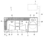
図1は、本発明の実施形態に係る空気調和機の室外機の概略的な平面図である。 FIG. 1 is a schematic plan view of an outdoor unit of an air conditioner according to an embodiment of the present invention.
図1に示すように、空気調和機1は、室外機2と室内機3とを含んでいる。空気調和機1の室外機2は、筐体11と、平面形状が略L字状の室外熱交換器12と、プロペラファン13およびプロペラファン13を回転駆動させる電動機15を含む送風機16と、圧縮機17と、四方弁18と、インバータ等の制御器19と、を備えている。室外熱交換器12、送風機16、圧縮機17、四方弁18、および制御器19は筐体11内に納められている。
As shown in FIG. 1, the
筐体11は、室外熱交換器12、送風機16、圧縮機17、四方弁18、および制御器19を支える底板21と、底板21を覆う本体カバー22と、を備えている。
The housing 11 includes an
筐体11内には、仕切板23が設けられている。仕切板23は、筐体11内に室外熱交換器12と送風機16を収容する熱交換室25と、圧縮機17、四方弁18、制御器19を収容する機械室26とを区画している。筐体11の背面および一方の側面は、熱交換室25に通じる空気の吸込口(図示省略)を有している。
A
筐体11の前面は、吹出口27を有している。吹出口27の周囲には、ベルマウス28が設けられている。ベルマウス28は、筐体11の前面の裏面から熱交換室25内に突出する所定の長さを有している。
The front surface of the housing 11 has an
送風機16は、吹出口27に対向している。送風機16のプロペラファン13は、ベルマウス28によって囲まれており、プロペラファン13が生じさせる空気の流れは、ベルマウス28に案内されて吹出口27から筐体11外へ吹き出す。筐体11の前面には、吹出口27の全面を覆うファンガード(図示省略)が設けられていて、安全性が確保されている。送風機16の電動機15は、筐体11の底板21に設けられるモータ固定板29にネジなどの固定具(図示省略)で固定されている。
The
室外機2は、冷媒配管31を介して室内機3に接続されている。冷凍サイクルの運転が開始されると圧縮機17が駆動される。駆動する圧縮機17は、冷媒配管に冷媒を流通させて室外熱交換器12へ導く。同時に送風機16の運転が開始される。電動機15はプロペラファン13を回転駆動させる。
The
外気は筐体11の背面と側面の吸込口から熱交換室25に導かれ、室外熱交換器12を通過して、室外熱交換器12内の冷媒と熱交換する。室外熱交換器12で熱交換した空気は、送風機16を介してベルマウス28に案内され、筐体11の前面の吹出口27から外部へ排出される。
The outside air is led to the
次に、プロペラファン13について詳細に説明する。
Next, the
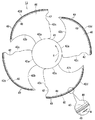
図2は、本発明の実施形態に係るプロペラファンの背面図である。 FIG. 2 is a rear view of the propeller fan according to the embodiment of the present invention.
図3は、本発明の実施形態に係るプロペラファンの径方向における厚肉部の断面図である。 FIG. 3 is a cross-sectional view of the thick portion in the radial direction of the propeller fan according to the embodiment of the present invention.
なお、プロペラファン13は、筐体11の正面にプロペラファン13の正面を向けた状態で筐体11に納められている。
The
図2および図3に示すように、本実施形態に係るプロペラファン13は、中央に配置されるハブ41と、ハブ41の周囲に設けられる複数の翼としてのブレード42と、を備えている。なお、プロペラファン13の正面は翼の正圧面45であり、背面は翼の負圧面46である。プロペラファン13が回転駆動されると、翼の負圧面46側から翼の正圧面45側へ、回転軸に沿って送風される。
As shown in FIGS. 2 and 3, the
円筒状のハブ41はプロペラファン13の中心部に設けられている。ハブ41の中心は、プロペラファン13の回転中心に相当する。
The
複数のブレード42、例えば4つのブレード42、42、42、42は、ハブ41の周囲に等間隔に配置されて、ハブ41に一体に設けられている。それぞれのブレード42は、回転軸の軸芯方向に対して斜めに捩られている。なお、ブレード42は複数あれば良い。
A plurality of
ここで、ブレード42のハブ41と一体に連設される部分を根元部42aと呼び、プロペラファン13の回転方向(図2中の実線矢印R)前側を翼前縁部42bと呼び、回転方向後側を翼後縁部42cと呼び、翼前縁部42b外周端と翼後縁部42c外周端とを結ぶ端部を翼外周縁部42dと呼ぶ。
Here, the portion of the
プロペラファン13の回転にともなうブレード42上の空気の流れを基準にすると、翼前縁部42bは空気の流入側であり、翼後縁部42cは空気の流出側である。
Based on the air flow on the
翼前縁部42bの輪郭線は、根元部42a側よりも翼外周縁部42d側の方が回転方向(図2中の実線矢印R)へ大きく突き出している。
The outline of the blade leading
また、それぞれのブレード42は、翼外周縁部42d(つまり、ブレード42の外周縁)に沿って負圧面46側に設けられる厚肉部48を備えている。
Each
厚肉部48は、ブレード42の負圧面46から突出している。厚肉部48は、円弧、山形、矩形、および多角形を含む任意の形状で良い。また、厚肉部48の頂点あるいは頂上(つまり、ブレード42の負圧面46から最も離れている箇所)は、プロペラファン13の径方向において厚肉部48の中央にあっても良いし、ブレード42の根元部42a側に偏倚していても良いし、ブレード42の翼外周縁部42d側に偏倚していても良い。
The
また、厚肉部48は、ブレード42の外周に向かって開く複数の溝部49を有している。
The
溝部49は、厚肉部48の全長に渡って、円周方向に略等間隔に設けられている。なお、溝部49は、厚肉部48の一部、例えば翼前縁部42bに近い部分のみに設けられていても良いし、翼後縁部42cに近い部分のみに設けられていても良いし、翼前縁部42bおよび翼後縁部42cのいずれからも離れ、翼外周縁部42dの途中部分にのみ設けられていても良い。
The
厚肉部48は、ブレード42の負圧面46を基準とする突出高さhを有している。
The
プロペラファン13の溝部49は、厚肉部48の途中からプロペラファン13の径方向外側へ向かって延び、ブレード42の外周において開放されている。溝部49は、プロペラファン13の径方向に長さLを有し、プロペラファン13の周方向に幅Wを有し、プロペラファン13の回転中心に平行な方向に深さdを有している。
The
なお、溝部49の長さL、幅W、および深さdは、いずれも当該箇所における最大寸法を指し、一様な寸法でなくとも良く、例えば厚肉部48の形状に依拠して変化していても良いし、樹脂成形における抜き勾配を考慮して変化していても良い。本実施形態のように、円弧状の厚肉部48に設けられる溝部49は、厚肉部48の頂部を起点とする場合、または厚肉部48の頂部を横切る場合には、厚肉部48の頂部において最大寸法の深さdを顕現させる。なお、溝部49の幅Wは、隣り合う溝部49間の厚肉部の幅よりも小さいことが好ましい。
Note that the length L, the width W, and the depth d of the
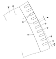
図4および図5は、本発明の実施形態に係るプロペラファンの厚肉部の拡大図である。 4 and 5 are enlarged views of the thick portion of the propeller fan according to the embodiment of the present invention.
図4に示すように、本実施形態に係るプロペラファン13の溝部49は、翼外周縁部42dの接線に垂直な方向へ向かって延びていても良い。
As shown in FIG. 4, the
また、図5に示すように、本実施形態に係るプロペラファン13の溝部49は、プロペラファン13の径方向に対して傾斜していても良い。すなわち、溝部49は、翼外周縁部42dの接線に垂直な方向に対して傾斜していても良い。図5は溝部49の翼外周縁部42d側の端部49aが、厚肉部48の途中にある端部49bに対し、プロペラファン13の回転方向(図5中の実線矢印R)、換言すると翼後縁部42c側へ位置するように傾斜させたものである。
As shown in FIG. 5, the
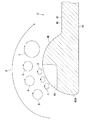
図6は、本発明の実施形態に係るプロペラファンの厚肉部における空気の流れを模式的に示す図である。 FIG. 6 is a diagram schematically showing the air flow in the thick portion of the propeller fan according to the embodiment of the present invention.
図7は、比較例のプロペラファンの厚肉部における空気の流れを模式的に示す図である。 FIG. 7 is a diagram schematically illustrating the air flow in the thick portion of the propeller fan of the comparative example.
図7の比較例のプロペラファン101は、溝部49のない一様な断面形状の厚肉部102をブレード103の負圧面106の翼外周縁部103dに備えている。
The
先ず、図7に示すように、比較例のプロペラファン101は、厚肉部102によってブレード103の正圧面105側から負圧面106側に巻き込まれる流れF2によって発生する渦S2を、ブレード103の根元側(ハブ側)に寄った位置で安定させる。
First, as shown in FIG. 7, the
他方、図6に示すように、本発明の実施形態に係るプロペラファン13は、厚肉部48に設けられる溝部49によって、比較例のプロペラファン101に生じる渦S2よりも小さい渦Sを生じさせ、ブレード42の正圧面45側から負圧面46側に巻き込まれる流れFがブレード42から剥離することを抑制し、風量性能をさらに向上させ、騒音をさらに低減させる。
On the other hand, as shown in FIG. 6, the
ところで、溝部49に生じる小さい渦Sは、溝部49の深さdに依存する。
By the way, the small vortex S generated in the
そこで、発明者は、ブレード42の負圧面46を基準とする厚肉部48の突出高さhに対し、溝部の深さdを0.2h以上かつ0.9h以下の範囲に設定することで、ブレード42の正圧面105側から負圧面106側に巻き込まれる流れFがブレード42から剥離することを抑制し、風量性能を向上させ、騒音を低減させることを見出した。
Therefore, the inventor sets the depth d of the groove to a range of 0.2 h or more and 0.9 h or less with respect to the protrusion height h of the
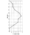
図8は、本実施形態に係るプロペラファンの送風性能測定実験の実験データを示す図である。 FIG. 8 is a diagram showing experimental data of a blowing performance measurement experiment of the propeller fan according to the present embodiment.
図8は、本実施形態に係るプロペラファン13の送風騒音の低減効果を示している。図8は、溝部49の深さdを横軸に取り、プロペラファン13回転時の騒音の低減割合を縦軸に取って、その相関関係を示している。
FIG. 8 shows the effect of reducing the blowing noise of the
なお、溝部49の深さdは、厚肉部48の突出高さhに対する比率で示され、0.1hから1hの範囲に設定した。
In addition, the depth d of the
また、プロペラファン13回転時の騒音の低減割合は、溝部49の深さdが0h、つまり、溝部49のない比較例のプロペラファン101を基準にした。
Further, the reduction ratio of the noise when the
図8から、溝部49の深さdを0.2h以上かつ0.9h以下の範囲に設定することで、プロペラファン13の送風騒音を低減できることが分かる。
From FIG. 8, it can be seen that the blowing noise of the
また、樹脂製のプロペラファン13において、厚肉部48および溝部49の成形性を考慮すると、溝部49の深さdは、0.9h以下に設定されていることが好ましい。
Further, in the
本実施形態に係るプロペラファン13および熱源ユニットである室外機2は、厚肉部48に、ブレード42の外周に向かって開く複数の溝部49を有することによって、従来のプロペラファンよりも小さい渦Sを生じさせ、ブレード42の正圧面105側から負圧面106側に巻き込まれる流れFがブレード42から剥離することを抑制し、風量性能をさらに向上させ、騒音をさらに低減させる。
The
また、本実施形態に係るプロペラファン13および熱源ユニットである室外機2は、厚肉部48に、ブレード42の外周に向かって開く複数の溝部49を有することによって、風量性能を向上させ、騒音を低減できるので、厚肉部48の突出高さhを従来のプロペラファンよりも低めに抑えても同等の整流効果、騒音低減効果を得ることが可能であり、ひいては、樹脂製のプロペラファン13における成形性を高め、成形不良を抑制できる。
In addition, the
さらに、本実施形態に係るプロペラファン13および熱源ユニットである室外機2は、溝部49の深さdを0.2h以上かつ0.9h以下の範囲に設定することで、風量性能の向上効果、騒音の低減効果、および成形性の向上効果を確実に得ることができる。
Furthermore, the
したがって、本実施形態のプロペラファン13および熱源ユニットである空気調和機1の室外機2によれば、ブレード42の正圧面45側から負圧面46側に巻き込まれる流れFを整流し、渦Sの抑制を図る一方で、厚肉部48の高さを抑え、ひいては成形不良を抑制することができる。
Therefore, according to the
本発明のいくつかの実施形態を説明したが、これらの実施形態は、例として提示したものであり、発明の範囲を限定することは意図していない。これら新規な実施形態は、その他の様々な形態で実施されることが可能であり、発明の要旨を逸脱しない範囲で、種々の省略、置き換え、変更を行うことができる。これら実施形態やその変形は、発明の範囲や要旨に含まれるとともに、特許請求の範囲に記載された発明とその均等の範囲に含まれる。 Although several embodiments of the present invention have been described, these embodiments are presented by way of example and are not intended to limit the scope of the invention. These novel embodiments can be implemented in various other forms, and various omissions, replacements, and changes can be made without departing from the scope of the invention. These embodiments and modifications thereof are included in the scope and gist of the invention, and are included in the invention described in the claims and the equivalents thereof.
1…空気調和機、2…室外機、3…室内機、11…筐体、12…室外熱交換器、13…プロペラファン、15…電動機、16…送風機、17…圧縮機、18…四方弁、19…制御器、21…底板、22…本体カバー、23…仕切板、25…熱交換室、26…機械室、27…吹出口、28…ベルマウス、29…モータ固定板、31…冷媒配管、41…ハブ、42…ブレード、42a…根元部、42b…翼前縁部、42c…翼後縁部、42d…翼外周縁部、45…正圧面、46…負圧面、48…厚肉部、49…溝部、49a…端部、49b…端部、101…プロペラファン、102…厚肉部、103…ブレード、103d…翼外周縁部、105…正圧面、106…負圧面。
DESCRIPTION OF
Claims (3)
前記ハブの周囲に設けられる複数の翼と、
前記翼の外周縁部に沿って負圧面側に設けられる厚肉部と、を備え、
前記厚肉部は、前記翼の外周に向かって開く複数の溝部を有するプロペラファン。 A hub located in the center;
A plurality of wings provided around the hub;
A thick portion provided on the suction surface side along the outer peripheral edge of the wing, and
The thick-walled portion is a propeller fan having a plurality of grooves that open toward the outer periphery of the blade.
前記プロペラファンによって流動する空気と熱交換する熱交換器と、を備える熱源ユニット。 The propeller fan according to claim 1 or 2,
A heat source unit comprising: a heat exchanger that exchanges heat with air flowing by the propeller fan.
Priority Applications (1)
| Application Number | Priority Date | Filing Date | Title |
|---|---|---|---|
| JP2016006977A JP6588833B2 (en) | 2016-01-18 | 2016-01-18 | Propeller fan and heat source unit |
Applications Claiming Priority (1)
| Application Number | Priority Date | Filing Date | Title |
|---|---|---|---|
| JP2016006977A JP6588833B2 (en) | 2016-01-18 | 2016-01-18 | Propeller fan and heat source unit |
Publications (2)
| Publication Number | Publication Date |
|---|---|
| JP2017129018A true JP2017129018A (en) | 2017-07-27 |
| JP6588833B2 JP6588833B2 (en) | 2019-10-09 |
Family
ID=59396611
Family Applications (1)
| Application Number | Title | Priority Date | Filing Date |
|---|---|---|---|
| JP2016006977A Active JP6588833B2 (en) | 2016-01-18 | 2016-01-18 | Propeller fan and heat source unit |
Country Status (1)
| Country | Link |
|---|---|
| JP (1) | JP6588833B2 (en) |
Cited By (1)
| Publication number | Priority date | Publication date | Assignee | Title |
|---|---|---|---|---|
| CN113236602A (en) * | 2021-06-15 | 2021-08-10 | 珠海格力电器股份有限公司 | Axial flow fan blade, axial flow fan and air conditioner |
Families Citing this family (1)
| Publication number | Priority date | Publication date | Assignee | Title |
|---|---|---|---|---|
| KR102495315B1 (en) * | 2022-01-27 | 2023-02-06 | 김윤성 | An axial flow impeller having a self-balancing function by a balancing groove and an axial flow pump having the same |
Citations (3)
| Publication number | Priority date | Publication date | Assignee | Title |
|---|---|---|---|---|
| JP2005248770A (en) * | 2004-03-03 | 2005-09-15 | Matsushita Electric Ind Co Ltd | Blower |
| JP2009036187A (en) * | 2007-07-11 | 2009-02-19 | Daikin Ind Ltd | Propeller fan |
| JP2013213420A (en) * | 2012-04-02 | 2013-10-17 | Panasonic Corp | Fan and outside unit using the same |
-
2016
- 2016-01-18 JP JP2016006977A patent/JP6588833B2/en active Active
Patent Citations (3)
| Publication number | Priority date | Publication date | Assignee | Title |
|---|---|---|---|---|
| JP2005248770A (en) * | 2004-03-03 | 2005-09-15 | Matsushita Electric Ind Co Ltd | Blower |
| JP2009036187A (en) * | 2007-07-11 | 2009-02-19 | Daikin Ind Ltd | Propeller fan |
| JP2013213420A (en) * | 2012-04-02 | 2013-10-17 | Panasonic Corp | Fan and outside unit using the same |
Cited By (1)
| Publication number | Priority date | Publication date | Assignee | Title |
|---|---|---|---|---|
| CN113236602A (en) * | 2021-06-15 | 2021-08-10 | 珠海格力电器股份有限公司 | Axial flow fan blade, axial flow fan and air conditioner |
Also Published As
| Publication number | Publication date |
|---|---|
| JP6588833B2 (en) | 2019-10-09 |
Similar Documents
| Publication | Publication Date | Title |
|---|---|---|
| KR100934556B1 (en) | Centrifugal fan and air conditioner using it | |
| JP6019391B2 (en) | Centrifugal blower and clothes dryer having the same | |
| WO2016006217A1 (en) | Propeller fan and blower unit | |
| JP2007170331A (en) | Indoor unit of turbo fan and air conditioner using the same | |
| US11674520B2 (en) | Centrifugal fan and air-conditioning apparatus | |
| JPH1144432A (en) | Air conditioner | |
| JP6592358B2 (en) | Propeller fan and heat source unit | |
| WO2016071948A1 (en) | Propeller fan, propeller fan device, and outdoor equipment for air-conditioning device | |
| JP6611676B2 (en) | Outdoor unit for blower and refrigeration cycle equipment | |
| CN110506164B (en) | Propeller fans and outdoor units for air conditioners | |
| AU2007234497A1 (en) | Multiblade centrifugal blower | |
| WO2019030868A1 (en) | Propeller fan, blower device, and refrigeration cycle device | |
| JP6588833B2 (en) | Propeller fan and heat source unit | |
| KR101996052B1 (en) | Air conditioner | |
| JP2004353510A (en) | Centrifugal blower and air conditioner equipped with centrifugal blower | |
| JP2007205268A (en) | Centrifugal fan | |
| JP6710337B2 (en) | Air conditioner | |
| JP6625213B2 (en) | Multi-blade fan and air conditioner | |
| CN205503552U (en) | Propeller type fan and heat source unit | |
| JP2016017458A (en) | Fan housing and blower unit | |
| JP2007198280A (en) | Centrifugal fan | |
| JP6692456B2 (en) | Outdoor unit of propeller fan and air conditioner | |
| JP5962712B2 (en) | Propeller fan and blower unit | |
| CN116848323A (en) | Fans and indoor units | |
| JP2016037884A (en) | Blower |
Legal Events
| Date | Code | Title | Description |
|---|---|---|---|
| A621 | Written request for application examination |
Free format text: JAPANESE INTERMEDIATE CODE: A621 Effective date: 20180801 |
|
| A977 | Report on retrieval |
Free format text: JAPANESE INTERMEDIATE CODE: A971007 Effective date: 20190530 |
|
| A131 | Notification of reasons for refusal |
Free format text: JAPANESE INTERMEDIATE CODE: A131 Effective date: 20190618 |
|
| A521 | Request for written amendment filed |
Free format text: JAPANESE INTERMEDIATE CODE: A523 Effective date: 20190710 |
|
| A131 | Notification of reasons for refusal |
Free format text: JAPANESE INTERMEDIATE CODE: A131 Effective date: 20190723 |
|
| A521 | Request for written amendment filed |
Free format text: JAPANESE INTERMEDIATE CODE: A523 Effective date: 20190819 |
|
| TRDD | Decision of grant or rejection written | ||
| A01 | Written decision to grant a patent or to grant a registration (utility model) |
Free format text: JAPANESE INTERMEDIATE CODE: A01 Effective date: 20190827 |
|
| A61 | First payment of annual fees (during grant procedure) |
Free format text: JAPANESE INTERMEDIATE CODE: A61 Effective date: 20190913 |
|
| R150 | Certificate of patent or registration of utility model |
Ref document number: 6588833 Country of ref document: JP Free format text: JAPANESE INTERMEDIATE CODE: R150 |