CN113236602A - Axial flow fan blade, axial flow fan and air conditioner - Google Patents
Axial flow fan blade, axial flow fan and air conditioner Download PDFInfo
- Publication number
- CN113236602A CN113236602A CN202110661022.2A CN202110661022A CN113236602A CN 113236602 A CN113236602 A CN 113236602A CN 202110661022 A CN202110661022 A CN 202110661022A CN 113236602 A CN113236602 A CN 113236602A
- Authority
- CN
- China
- Prior art keywords
- axial
- flow fan
- fan blade
- radial
- blade according
- Prior art date
- Legal status (The legal status is an assumption and is not a legal conclusion. Google has not performed a legal analysis and makes no representation as to the accuracy of the status listed.)
- Pending
Links
Images


Classifications
-
- F—MECHANICAL ENGINEERING; LIGHTING; HEATING; WEAPONS; BLASTING
- F04—POSITIVE - DISPLACEMENT MACHINES FOR LIQUIDS; PUMPS FOR LIQUIDS OR ELASTIC FLUIDS
- F04D—NON-POSITIVE-DISPLACEMENT PUMPS
- F04D29/00—Details, component parts, or accessories
- F04D29/26—Rotors specially for elastic fluids
- F04D29/32—Rotors specially for elastic fluids for axial flow pumps
- F04D29/325—Rotors specially for elastic fluids for axial flow pumps for axial flow fans
-
- F—MECHANICAL ENGINEERING; LIGHTING; HEATING; WEAPONS; BLASTING
- F04—POSITIVE - DISPLACEMENT MACHINES FOR LIQUIDS; PUMPS FOR LIQUIDS OR ELASTIC FLUIDS
- F04D—NON-POSITIVE-DISPLACEMENT PUMPS
- F04D29/00—Details, component parts, or accessories
- F04D29/26—Rotors specially for elastic fluids
- F04D29/32—Rotors specially for elastic fluids for axial flow pumps
- F04D29/38—Blades
- F04D29/388—Blades characterised by construction
-
- F—MECHANICAL ENGINEERING; LIGHTING; HEATING; WEAPONS; BLASTING
- F04—POSITIVE - DISPLACEMENT MACHINES FOR LIQUIDS; PUMPS FOR LIQUIDS OR ELASTIC FLUIDS
- F04D—NON-POSITIVE-DISPLACEMENT PUMPS
- F04D29/00—Details, component parts, or accessories
- F04D29/66—Combating cavitation, whirls, noise, vibration or the like; Balancing
- F04D29/661—Combating cavitation, whirls, noise, vibration or the like; Balancing especially adapted for elastic fluid pumps
- F04D29/666—Combating cavitation, whirls, noise, vibration or the like; Balancing especially adapted for elastic fluid pumps by means of rotor construction or layout, e.g. unequal distribution of blades or vanes
-
- F—MECHANICAL ENGINEERING; LIGHTING; HEATING; WEAPONS; BLASTING
- F04—POSITIVE - DISPLACEMENT MACHINES FOR LIQUIDS; PUMPS FOR LIQUIDS OR ELASTIC FLUIDS
- F04D—NON-POSITIVE-DISPLACEMENT PUMPS
- F04D29/00—Details, component parts, or accessories
- F04D29/66—Combating cavitation, whirls, noise, vibration or the like; Balancing
- F04D29/661—Combating cavitation, whirls, noise, vibration or the like; Balancing especially adapted for elastic fluid pumps
- F04D29/667—Combating cavitation, whirls, noise, vibration or the like; Balancing especially adapted for elastic fluid pumps by influencing the flow pattern, e.g. suppression of turbulence
Landscapes
- Engineering & Computer Science (AREA)
- Mechanical Engineering (AREA)
- General Engineering & Computer Science (AREA)
- Structures Of Non-Positive Displacement Pumps (AREA)
Abstract
The application provides an axial fan blade, axial fan and air conditioner, including wheel hub portion and blade body, the blade body is followed the circumference of wheel hub portion arranges, the blade body includes the pressure surface, be provided with the matte section on the pressure surface, the matte section is followed the pressure surface is kept away from the edge setting of the one end of wheel hub portion. The application provides an axial fan blade, axial fan and air conditioner can restrain apex leakage vortex's intensity, promotes the acting efficiency of fan blade, reduces the aerodynamic noise when the fan operates.
Description
Technical Field
The application belongs to the technical field of air conditioning, and particularly relates to an axial flow fan blade, an axial flow fan and an air conditioner.
Background
The tip leakage vortex of the axial-flow fan blade is one of the key factors influencing the aerodynamic characteristics and the wind noise level of the fan blade all the time, the tip leakage vortex is arranged at the outermost edge of the axial-flow fan blade, the axial-flow fan blade is generally matched with a flow guide ring for use, and a gap exists between the tip of the fan blade and the flow guide ring. Pressure difference exists between the pressure surface and the suction surface of the blade, and fluid flows along the action direction of the pressure difference. When the airflow turns over the pressure surface and flows to the suction surface, the airflow is separated because the airflow cannot completely adhere to the surface of the blade to flow under the action of viscous force and inertia force. The part of the airflow which is subjected to flow shedding can develop to form vortex, and the vortex is continuously enhanced until the viscous force among the airflow can not restrict the airflow, the vortex is shed, the work capacity of the fan blade can be reduced due to vortex shedding, the efficiency is reduced, and the vortex shedding is equivalent to that part of high-pressure fluid which is acted by the fan blade flows back to the low-pressure side of the air inlet again to generate flow leakage. Especially, the axial flow fan blade applied to the field of air conditioners adopts a semi-open type air supply structure, leakage vortex is obviously existed at the outer edge of the axial flow fan blade, the acting efficiency of the fan blade is reduced, the pneumatic noise of the fan during operation is greatly increased, and how to effectively control the strength and the scale of the blade tip leakage vortex becomes one of key technology brakes for improving the pneumatic performance of the axial flow fan blade and reducing the noise level.
Disclosure of Invention
Therefore, the technical problem to be solved by the application is to provide an axial flow fan blade, an axial flow fan and an air conditioner, which can inhibit the leakage vortex strength of the blade tip, improve the work efficiency of the fan blade and reduce the pneumatic noise when the fan operates.
In order to solve the problem, the application provides an axial flow fan blade, including wheel hub portion and blade body, the blade body is followed the circumference of wheel hub portion arranges, the blade body includes the pressure surface, be provided with the matte section on the pressure surface, the matte section is followed the pressure surface is kept away from the edge setting of the one end of wheel hub portion.
Optionally, the roughened surface section extends to an edge of an end of the pressure surface remote from the hub portion.
Optionally, the area of the rough surface section accounts for 5% -25% of the area of the pressure surface.
Optionally, the roughened surface section comprises grooves and/or protrusions.
Optionally, the rough surface section includes a radial groove, and the radial groove is arranged on the pressure surface along the radial direction of the axial flow fan blade.
Optionally, the radial slots extend along a curved line or a straight line.
Optionally, when a plurality of radial slots are provided, the distance between adjacent radial slots is a, and a is greater than or equal to 1.5mm and less than or equal to 5 mm.
Optionally, the radial groove penetrates through the rough surface section along the radial direction of the axial flow fan blade.
Optionally, the rough surface section includes a circumferential groove, and the circumferential groove is arranged on the pressure surface along the circumferential direction of the axial flow fan blade.
Optionally, the circumferential groove extends along a curve.
Optionally, when a plurality of circumferential grooves are provided, the distance between adjacent circumferential grooves is a, and a is greater than or equal to 1.5mm and less than or equal to 5 mm.
Optionally, the circumferential groove penetrates through the rough surface section along the circumferential direction of the axial-flow fan blade.
Optionally, an included angle formed by the radial groove and the circumferential groove is b, and b is more than or equal to 15 degrees and less than or equal to 35 degrees.
Optionally, the cross section of the radial groove and/or the circumferential groove is triangular, trapezoidal or rectangular.
Optionally, the cross section of the radial groove and/or the circumferential groove is an isosceles triangle, the height of the isosceles triangle is h, the length of the base is L, the angle of the base angle is c, h is greater than or equal to 0.2mm and less than or equal to 2mm, L is greater than or equal to 1mm and less than or equal to 5mm, and c is greater than or equal to 5 degrees and less than or equal to 45 degrees.
Another aspect of the present application provides an axial flow fan, including the axial flow fan blade as above.
In another aspect of the present application, an air conditioner is provided, which includes the above axial flow fan blade.
Advantageous effects
The axial flow fan blade, the axial flow fan and the air conditioner provided by the embodiment of the invention can inhibit the leakage vortex strength of the blade tip, improve the acting efficiency of the fan blade and reduce the pneumatic noise of the fan during operation.
Drawings
Fig. 1 is a schematic perspective view of an axial-flow fan blade according to an embodiment of the present application;
FIG. 2 is a front view of an axial flow fan according to an embodiment of the present application;
FIG. 3 is a schematic structural view of a blade body according to an embodiment of the present application;
FIG. 4 is an enlarged view taken at A in FIG. 3;
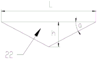
fig. 5 is a schematic structural diagram of a radial groove according to an embodiment of the present application.
The reference numerals are represented as:
1. a hub portion; 2. a blade body; 21. a radial slot; 22. a circumferential groove.
Detailed Description
With reference to fig. 1 to 5, according to an embodiment of the present application, an axial flow fan blade includes a hub portion 1 and a blade body 2, the blade body 2 is arranged along a circumferential direction of the hub portion 1, the blade body 2 includes a pressure surface, the pressure surface is provided with a rough surface section, the rough surface section is arranged along an edge of one end of the pressure surface far away from the hub portion 1, and by arranging the rough surface section, a tip leakage vortex can be inhibited from dropping, an outer edge acting efficiency is improved, a power consumption with an air volume is reduced, and a pneumatic performance of a fan is improved. The radial channeling of the air flow at one end of the pressure surface, which is far away from the hub part 1, along the pressure surface to the suction surface is restrained, the tip leakage vortex size is reduced, the pneumatic noise during operation is reduced, and the tone quality is improved.
Further, the axial flow fan blade includes at least two blade bodies 2, and the blade bodies 2 are arranged along the circumference of the hub portion 1.
Further, the blade body 2 comprises a pressure side and a suction side, the suction side being located at a backside of the pressure side.
Further, blade body 2 includes apex and root, and the root meets with hub portion 1, and the apex is the one end of blade body 2 keeping away from hub portion 1 promptly, and the matte section sets up along the apex promptly, and extends along the apex.
Further, as shown in fig. 1 to 3, the rough surface section extends from one circumferential side to the other circumferential side of the blade body 2.
Further, the surface of the rough surface section is a rough surface, i.e. a non-smooth surface.
The rough surface section extends to the edge of one end of the pressure surface far away from the hub part, so that the good effect of inhibiting the blade tip leakage vortex from falling off can be ensured.
The area of the rough surface section accounts for 5% -25% of the area of the pressure surface, and the good effect of inhibiting the blade tip leakage vortex from falling off can be ensured.
Further, the width of the rough surface section, i.e. the length of the rough surface section along the radial direction of the hub part 1, may be equal or different, but the total area accounts for 5% -25% of the area of the pressure surface.
Specifically, the width of the rough surface section is equal.
The rough surface section comprises grooves and/or protrusions which can form unsmooth surfaces, and the good effect of inhibiting the blade tip leakage vortex from falling off is guaranteed.
Furthermore, a groove can be formed on the pressure surface along the thickness direction of the blade body 2 to form a rough surface section. The pressure surface can also be provided with bulges, namely convex ribs, along the thickness direction of the blade body 2, and grooves or rough surface sections are formed between two adjacent convex ribs.
Specifically, a groove is formed in the pressure surface along the thickness direction of the blade body 2 to form a rough surface section.
The rough surface section comprises a radial groove 21, the radial groove 21 is arranged on the pressure surface along the radial direction of the axial flow fan blade, and the radial groove 21 is arranged, so that the blade tip leakage vortex can be effectively inhibited from falling off, the outer edge work efficiency is improved, the same air volume power consumption is reduced, and the pneumatic performance of the fan is improved. The radial channeling of the air flow at one end of the pressure surface, which is far away from the hub part 1, along the pressure surface to the suction surface is restrained, the tip leakage vortex size is reduced, the pneumatic noise during operation is reduced, and the tone quality is improved.
The radial groove 21 extends along a curved line or a straight line, and can further ensure a good effect of suppressing the tip leakage vortex from falling off.
In particular, the radial slots 21 extend along a curved line.
When a plurality of radial grooves 21 are provided, the distance between adjacent radial grooves 21 is a, and a is more than or equal to 1.5mm and less than or equal to 5mm, so that the radial grooves 21 can sufficiently restrain tip leakage vortexes.
Further, when the radial grooves 21 are plural, the plural radial grooves 21 are arranged equidistantly or non-equidistantly in the circumferential direction of the hub portion 1.
Specifically, in the present embodiment, when the number of the radial grooves 21 is plural, the radial grooves 21 are uniformly arranged on the pressure surface in the circumferential direction of the hub portion 1.
The radial groove 21 penetrates through the rough surface section along the radial direction of the axial flow fan blade, and the radial groove 21 is guaranteed to fully restrain tip leakage vortex.
The rough surface section comprises a circumferential groove 22, the circumferential groove 22 is formed in the pressure surface along the circumferential direction of the axial flow fan blade, and the circumferential groove 22 can effectively restrain blade tip leakage vortex from falling off, improves outer edge work efficiency, reduces power consumption with the air volume, and improves the pneumatic performance of the fan. The radial channeling of the air flow at one end of the pressure surface, which is far away from the hub part 1, along the pressure surface to the suction surface is restrained, the tip leakage vortex size is reduced, the pneumatic noise during operation is reduced, and the tone quality is improved.
The circumferential groove 22 extends along a curve, and can largely suppress the range of tip leakage vortex, thereby improving the suppression effect.
Further, the circumferential groove 22 extends in an arc shape.
Specifically, the arc of the circumferential groove 22 is the same as the arc of the blade tip.
Further, when the circumferential groove 22 is plural, the plural circumferential grooves 22 are arranged in the radial direction of the hub portion 1 at equal intervals or at non-equal intervals.
Specifically, in the present embodiment, when the circumferential groove 22 is plural, the plural circumferential grooves 22 are arranged at equal intervals in the radial direction of the hub portion 1. The distance between adjacent circumferential grooves 22 is a, and a is more than or equal to 1.5mm and less than or equal to 5mm, so that the radial grooves 21 can fully restrain tip leakage vortex.
The circumferential groove 22 penetrates through the rough surface section along the circumferential direction of the axial flow fan blade, so that the range of inhibiting tip leakage vortex to the maximum is ensured, and the inhibiting effect is improved.
Further, the circumferential groove 22 is provided to intersect with the radial groove 21.
The included angle between the radial groove 21 and the circumferential groove 22 is b, and b is more than or equal to 15 degrees and less than or equal to 35 degrees.
The circumferential grooves 22 and the radial grooves 21 are arranged on the outer edge of the pressure surface in a crossed mode to form a net-shaped rough surface section, the rough surface section is matched with appropriate size parameters, the flow energy of outer edge radial cross flow can be effectively consumed, outer edge flow leakage is reduced, and the acting efficiency of the axial flow fan blade is improved. Meanwhile, the rough surface section can inhibit the forming of large scale vortexes at the outer edge, energy is dispersed to small scale vortex groups in the rough surface section, the scale and the intensity of the large vortexes are inhibited, noise radiation can be carried out on the vortexes of different scales in a wider frequency range, and tone quality modulation is achieved.
The cross section of the radial groove 21 and/or the circumferential groove 22 is triangular, trapezoidal or rectangular, so that the radial groove 21 and/or the circumferential groove 22 has a good tip leakage vortex suppression effect and a good noise reduction effect.
Specifically, the radial grooves 21 and the circumferential grooves 22 are triangular in cross section.
The cross section of the radial groove 21 and/or the circumferential groove 22 is an isosceles triangle, the height of the isosceles triangle is h, the length of the base is L, the angle of the base angle is c, h is more than or equal to 0.2mm and less than or equal to 2mm, L is more than or equal to 1mm and less than or equal to 5mm, and c is more than or equal to 5 degrees and less than or equal to 45 degrees.
The simulation comparison data is shown in table 1 below.
TABLE 1
| Blade | Rotational speed 1-air volume | Rotational speed 1-power |
| Prior Art | 5677.02 | 243.5 |
| Example 1 | 5701.98 | 240.51 |
| Example 2 | 5697.17 | 241.56 |
The fan blades in the embodiment 1 and the embodiment 2 are the same as the fan blades in the prior art except that the rough surface sections are arranged. The number of the circumferential grooves, the depth/angle of the circumferential grooves, the width of the circumferential grooves, the included angle between the circumferential grooves and the radial grooves, the depth of the radial grooves, the included angle between the radial grooves, and the width of the radial grooves in the embodiment 1 are the same as those in the embodiment 2, the distances between the adjacent radial grooves in the embodiment 1 are different from each other, the distance between the adjacent radial grooves in the embodiment 1 is 2.5mm, and the distance between the adjacent radial grooves in the embodiment 2 is 4 mm. In the prior art, the air volume is 5677.02 and the power is 243.5w at the rotating speed of 1. In the embodiment 1, the air volume is 5701.98 and the power is 240.51w at the rotating speed of 1, compared with the prior art, the air volume change range is 0.44% at the same rotating speed, and the power change range is-2.56% at the same air volume. In the embodiment 2, the air volume is 5697.17 and the power is 241.56w at the rotating speed 1, compared with the prior art, the air volume change range is 0.35% at the same rotating speed, and the power change range is-1.89% at the same air volume.
In another aspect of this embodiment, an axial flow fan is provided, including the above axial flow fan blade.
In another aspect of this embodiment, an air conditioner is provided, which includes the above axial-flow fan blade.
The axial flow fan blade, the axial flow fan and the air conditioner provided by the embodiment of the invention can inhibit the leakage vortex strength of the blade tip, improve the acting efficiency of the fan blade and reduce the pneumatic noise of the fan during operation.
It is readily understood by a person skilled in the art that the advantageous ways described above can be freely combined, superimposed without conflict.
The present invention is not intended to be limited to the particular embodiments shown and described, but is to be accorded the widest scope consistent with the principles and novel features herein disclosed. The foregoing is only a preferred embodiment of the present application, and it should be noted that, for those skilled in the art, several modifications and variations can be made without departing from the technical principle of the present application, and these modifications and variations should also be considered as the protection scope of the present application.
Claims (17)
1. The axial flow fan blade is characterized by comprising a hub part (1) and a blade body (2), wherein the blade body (2) is arranged along the circumferential direction of the hub part (1), the blade body (2) comprises a pressure surface, a rough surface section is arranged on the pressure surface, and the rough surface section is arranged along the edge of one end, far away from the hub part (1), of the pressure surface.
2. The axial fan blade according to claim 1, wherein the rough surface section extends to the edge of the end of the pressure surface remote from the hub portion (1).
3. The axial-flow fan blade according to claim 1, wherein the area of the rough surface section accounts for 5% -25% of the area of the pressure surface.
4. The axial flow fan blade according to claim 1, wherein the roughened surface section comprises grooves and/or protrusions.
5. The axial-flow fan blade according to claim 1, wherein the rough surface section comprises a radial groove (21), and the radial groove (21) is arranged on the pressure surface along the radial direction of the axial-flow fan blade.
6. The axial-flow blade according to claim 5, characterized in that said radial slots (21) extend along a curved or rectilinear line.
7. The axial-flow fan blade according to claim 5, wherein when the radial slots (21) are multiple, the distance between adjacent radial slots (21) is a, and a is more than or equal to 1.5mm and less than or equal to 5 mm.
8. The axial-flow blade according to claim 5, characterized in that said radial slots (21) penetrate said rough surface section in the radial direction of said axial-flow blade.
9. The axial flow blade of claim 5, wherein said rough surface section comprises a circumferential groove (22), said circumferential groove (22) being disposed on a pressure surface in a circumferential direction of said axial flow blade.
10. The axial fan blade according to claim 9, characterized in that said circumferential groove (22) extends along a curve.
11. The axial-flow fan blade according to claim 9, wherein when the circumferential grooves (22) are multiple, the distance between adjacent circumferential grooves (22) is a, and a is greater than or equal to 1.5mm and less than or equal to 5 mm.
12. The axial-flow blade according to claim 9, wherein the circumferential groove (22) penetrates the rough-surface section in the circumferential direction of the axial-flow blade.
13. The axial-flow fan blade according to claim 9, characterized in that the angle between the radial slots (21) and the circumferential slots (22) is b, b being greater than or equal to 15 ° and less than or equal to 35 °.
14. The axial-flow blade according to claim 9, characterized in that the cross section of said radial slots (21) and/or of said circumferential slots (22) is triangular or trapezoidal or rectangular.
15. The axial-flow fan blade according to claim 9, wherein the cross section of the radial groove (21) and/or the circumferential groove (22) is an isosceles triangle, the height of the isosceles triangle is h, the base length is L, the angle of the base angle is c, 0.2mm < h < 2mm, 1mm < L < 5mm, and 5 ° < c < 45 °.
16. An axial flow fan comprising the axial flow fan blade according to any one of claims 1 to 15.
17. An air conditioner characterized by comprising the axial-flow fan blade as claimed in any one of claims 1 to 15.
Priority Applications (1)
| Application Number | Priority Date | Filing Date | Title |
|---|---|---|---|
| CN202110661022.2A CN113236602A (en) | 2021-06-15 | 2021-06-15 | Axial flow fan blade, axial flow fan and air conditioner |
Applications Claiming Priority (1)
| Application Number | Priority Date | Filing Date | Title |
|---|---|---|---|
| CN202110661022.2A CN113236602A (en) | 2021-06-15 | 2021-06-15 | Axial flow fan blade, axial flow fan and air conditioner |
Publications (1)
| Publication Number | Publication Date |
|---|---|
| CN113236602A true CN113236602A (en) | 2021-08-10 |
Family
ID=77139808
Family Applications (1)
| Application Number | Title | Priority Date | Filing Date |
|---|---|---|---|
| CN202110661022.2A Pending CN113236602A (en) | 2021-06-15 | 2021-06-15 | Axial flow fan blade, axial flow fan and air conditioner |
Country Status (1)
| Country | Link |
|---|---|
| CN (1) | CN113236602A (en) |
Cited By (1)
| Publication number | Priority date | Publication date | Assignee | Title |
|---|---|---|---|---|
| CN119146090A (en) * | 2024-10-29 | 2024-12-17 | 珠海格力电器股份有限公司 | Axial fan blade and axial fan with same |
Citations (8)
| Publication number | Priority date | Publication date | Assignee | Title |
|---|---|---|---|---|
| JP2000130396A (en) * | 1998-10-28 | 2000-05-12 | Sanyo Electric Co Ltd | Axial flow fan |
| US20120100001A1 (en) * | 2010-10-20 | 2012-04-26 | Zaward Corporation | Fan structure |
| WO2016164533A1 (en) * | 2015-04-08 | 2016-10-13 | Horton, Inc. | Fan blade surface features |
| JP2017129018A (en) * | 2016-01-18 | 2017-07-27 | 東芝キヤリア株式会社 | Propeller fan and heat source unit |
| CN107313979A (en) * | 2017-08-31 | 2017-11-03 | 广东美的制冷设备有限公司 | Axial-flow windwheel and the air conditioner with it |
| US20190301471A1 (en) * | 2018-02-07 | 2019-10-03 | Gd Midea Air-Conditioning Equipment Co., Ltd. | Axial flow wind wheel and air conditioner |
| CN111441977A (en) * | 2020-04-26 | 2020-07-24 | 宁波奥克斯电气股份有限公司 | Axial flow fan blade, fan assembly and air conditioner thereof |
| CN215486804U (en) * | 2021-06-15 | 2022-01-11 | 珠海格力电器股份有限公司 | Axial flow fan blade, axial flow fan and air conditioner |
-
2021
- 2021-06-15 CN CN202110661022.2A patent/CN113236602A/en active Pending
Patent Citations (8)
| Publication number | Priority date | Publication date | Assignee | Title |
|---|---|---|---|---|
| JP2000130396A (en) * | 1998-10-28 | 2000-05-12 | Sanyo Electric Co Ltd | Axial flow fan |
| US20120100001A1 (en) * | 2010-10-20 | 2012-04-26 | Zaward Corporation | Fan structure |
| WO2016164533A1 (en) * | 2015-04-08 | 2016-10-13 | Horton, Inc. | Fan blade surface features |
| JP2017129018A (en) * | 2016-01-18 | 2017-07-27 | 東芝キヤリア株式会社 | Propeller fan and heat source unit |
| CN107313979A (en) * | 2017-08-31 | 2017-11-03 | 广东美的制冷设备有限公司 | Axial-flow windwheel and the air conditioner with it |
| US20190301471A1 (en) * | 2018-02-07 | 2019-10-03 | Gd Midea Air-Conditioning Equipment Co., Ltd. | Axial flow wind wheel and air conditioner |
| CN111441977A (en) * | 2020-04-26 | 2020-07-24 | 宁波奥克斯电气股份有限公司 | Axial flow fan blade, fan assembly and air conditioner thereof |
| CN215486804U (en) * | 2021-06-15 | 2022-01-11 | 珠海格力电器股份有限公司 | Axial flow fan blade, axial flow fan and air conditioner |
Cited By (1)
| Publication number | Priority date | Publication date | Assignee | Title |
|---|---|---|---|---|
| CN119146090A (en) * | 2024-10-29 | 2024-12-17 | 珠海格力电器股份有限公司 | Axial fan blade and axial fan with same |
Similar Documents
| Publication | Publication Date | Title |
|---|---|---|
| CN204572556U (en) | Air conditioner outdoor machine and air conditioner | |
| US11078921B2 (en) | Blade, impeller and fan | |
| CN201574972U (en) | Axial flow wind wheel | |
| CN107313977B (en) | Centrifugal fan blade, centrifugal fan and air conditioner | |
| CN112283154A (en) | Axial Fans and Air Conditioners | |
| CN105275875A (en) | Centrifugal fan blade and centrifugal fan | |
| CN215486804U (en) | Axial flow fan blade, axial flow fan and air conditioner | |
| CN216241479U (en) | Blade for fan, axial flow fan and air treatment equipment | |
| CN113236602A (en) | Axial flow fan blade, axial flow fan and air conditioner | |
| CN103486081B (en) | Axial flow fan blade, fan and air conditioner outdoor unit | |
| CN102536900A (en) | Axial flow wind wheel | |
| CN103967839B (en) | Axial flow fan blade and air conditioner with same | |
| CN202628612U (en) | Axial flow fan blade, fan and air conditioner outdoor unit | |
| CN204610370U (en) | A kind of centrifugal impeller of blade trailing edge perforation | |
| WO2020125128A1 (en) | Axial flow fan blade, ventilation device and air conditioner | |
| CN206816552U (en) | Axial-flow windwheel and air conditioner | |
| CN213839013U (en) | Axial flow fan blade and air conditioner | |
| CN107355424B (en) | Axial flow fan blade and fan and air conditioner outdoor unit with same | |
| CN204493271U (en) | A kind of centrifugal blower fan blade wheel | |
| CN204553344U (en) | Double-sucking type centrifugal blower | |
| CN219139458U (en) | Backward centrifugal blade, courtyard machine fan blade and embedded air conditioner | |
| CN216343023U (en) | Locally-raised wave-shaped blade, centrifugal impeller and centrifugal ventilator | |
| CN216895054U (en) | Axial flow fan blade, axial flow fan and air conditioner | |
| CN214196763U (en) | Fan wheel subassembly, fan subassembly and fan | |
| CN104279188A (en) | Centrifugal fan and air conditioner with same |
Legal Events
| Date | Code | Title | Description |
|---|---|---|---|
| PB01 | Publication | ||
| PB01 | Publication | ||
| SE01 | Entry into force of request for substantive examination | ||
| SE01 | Entry into force of request for substantive examination | ||
| RJ01 | Rejection of invention patent application after publication |
Application publication date: 20210810 |
|
| RJ01 | Rejection of invention patent application after publication |