JP2017128267A - Pneumatic tire - Google Patents
Pneumatic tire Download PDFInfo
- Publication number
- JP2017128267A JP2017128267A JP2016009929A JP2016009929A JP2017128267A JP 2017128267 A JP2017128267 A JP 2017128267A JP 2016009929 A JP2016009929 A JP 2016009929A JP 2016009929 A JP2016009929 A JP 2016009929A JP 2017128267 A JP2017128267 A JP 2017128267A
- Authority
- JP
- Japan
- Prior art keywords
- tire
- protrusion
- radial direction
- circumferential direction
- length
- Prior art date
- Legal status (The legal status is an assumption and is not a legal conclusion. Google has not performed a legal analysis and makes no representation as to the accuracy of the status listed.)
- Granted
Links
Images
Classifications
-
- B—PERFORMING OPERATIONS; TRANSPORTING
- B60—VEHICLES IN GENERAL
- B60C—VEHICLE TYRES; TYRE INFLATION; TYRE CHANGING; CONNECTING VALVES TO INFLATABLE ELASTIC BODIES IN GENERAL; DEVICES OR ARRANGEMENTS RELATED TO TYRES
- B60C13/00—Tyre sidewalls; Protecting, decorating, marking, or the like, thereof
- B60C13/02—Arrangement of grooves or ribs
-
- B—PERFORMING OPERATIONS; TRANSPORTING
- B60—VEHICLES IN GENERAL
- B60C—VEHICLE TYRES; TYRE INFLATION; TYRE CHANGING; CONNECTING VALVES TO INFLATABLE ELASTIC BODIES IN GENERAL; DEVICES OR ARRANGEMENTS RELATED TO TYRES
- B60C11/00—Tyre tread bands; Tread patterns; Anti-skid inserts
- B60C11/01—Shape of the shoulders between tread and sidewall, e.g. rounded, stepped or cantilevered
-
- B—PERFORMING OPERATIONS; TRANSPORTING
- B60—VEHICLES IN GENERAL
- B60C—VEHICLE TYRES; TYRE INFLATION; TYRE CHANGING; CONNECTING VALVES TO INFLATABLE ELASTIC BODIES IN GENERAL; DEVICES OR ARRANGEMENTS RELATED TO TYRES
- B60C13/00—Tyre sidewalls; Protecting, decorating, marking, or the like, thereof
- B60C13/002—Protection against exterior elements
Abstract
Description
本発明は、サイドウォール部の外面にタイヤ軸方向外側に隆起するプロテクタを有する空気入りタイヤに関する。 The present invention relates to a pneumatic tire having a protector that protrudes outward in the tire axial direction on the outer surface of a sidewall portion.
従来、サイドウォール部の外面にタイヤ軸方向外側に隆起するプロテクタを有する空気入りタイヤが知られている。この種の空気入りタイヤは、例えば、悪路走行時に、鋭利な石等がサイドウォール部に衝突しても、プロテクタによって、サイドウォール部にカット傷が生じることが防止される。 Conventionally, a pneumatic tire having a protector that protrudes outward in the tire axial direction on the outer surface of the sidewall portion is known. In this type of pneumatic tire, for example, even when sharp stones or the like collide with the sidewall portion when traveling on a rough road, the protector prevents the sidewall portion from being cut.
例えば、下記特許文献1は、サイドウォール部のプロテクタの形状及び配設位置を限定することで、マッド性能と耐カット性能とを向上させた空気入りタイヤを提案している。 For example, the following Patent Document 1 proposes a pneumatic tire that improves the mud performance and the cut-proof performance by limiting the shape and arrangement position of the protector in the sidewall portion.
上記特許文献1は、サイドウォール部のプロテクタの隆起厚さを大きくすることで、耐カット性能を向上させることができる。しかしながら、サイドウォール部のプロテクタの隆起厚さが大きくなると、サイドウォール部が蓄熱し易くなり、その結果、空気入りタイヤの耐久性が低下するという問題があった。 Patent Document 1 can improve cut resistance by increasing the thickness of the protector in the side wall. However, when the raised thickness of the protector in the sidewall portion increases, the sidewall portion easily stores heat, and as a result, there is a problem in that the durability of the pneumatic tire decreases.
本発明は、以上のような実状に鑑み案出されたもので、プロテクタの単位隆起模様の形状を改善することを基本として、耐久性を向上させ得る空気入りタイヤを提供することを主たる目的としている。 The present invention has been devised in view of the actual situation as described above, and has as its main object to provide a pneumatic tire capable of improving durability on the basis of improving the shape of the unit raised pattern of the protector. Yes.
本発明は、少なくとも一方のサイドウォール部の外面に、タイヤ軸方向外側に隆起するプロテクタを有する空気入りタイヤであって、前記プロテクタは、複数の単位隆起模様がタイヤ周方向に離間して配されており、前記各単位隆起模様は、タイヤ周方向に離間して配されかつタイヤ半径方向にのびる第1突部及び第2突部と、前記第1突部及び前記第2突部をタイヤ周方向に連結する第3突部とを含み、前記第1突部のタイヤ半径方向長さは、前記第2突部のタイヤ半径方向長さよりも大きいことを特徴とする。 The present invention is a pneumatic tire having a protector that protrudes outward in the tire axial direction on an outer surface of at least one sidewall portion, wherein the protector has a plurality of unit raised patterns spaced apart in the tire circumferential direction. Each of the unit raised patterns includes a first protrusion and a second protrusion that are spaced apart from each other in the tire circumferential direction and extend in the tire radial direction, and the first protrusion and the second protrusion. And a length of the first protrusion in the tire radial direction is greater than a length of the second protrusion in the tire radial direction.
本発明に係る空気入りタイヤにおいて、前記第3突部は、前記第1突部のタイヤ半径方向の端部からタイヤ半径方向に離れた位置に連結されるのが望ましい。 In the pneumatic tire according to the present invention, it is desirable that the third protrusion is connected to a position away from the end in the tire radial direction of the first protrusion in the tire radial direction.
本発明に係る空気入りタイヤにおいて、前記第3突部は、前記第2突部のタイヤ半径方向の端部からタイヤ半径方向に離れた位置に連結されるのが望ましい。 In the pneumatic tire according to the present invention, it is desirable that the third protrusion is connected to a position away from an end of the second protrusion in the tire radial direction.
本発明に係る空気入りタイヤにおいて、前記第3突部は、前記第1突部及び前記第2突部のタイヤ半径方向の内端側に連結されるのが望ましい。 In the pneumatic tire according to the present invention, it is preferable that the third protrusion is connected to inner ends of the first protrusion and the second protrusion in the tire radial direction.
本発明に係る空気入りタイヤにおいて、前記第3突部は、タイヤ周方向に対して傾斜しているのが望ましい。 In the pneumatic tire according to the present invention, it is preferable that the third protrusion is inclined with respect to the tire circumferential direction.
本発明に係る空気入りタイヤにおいて、前記第1突部のタイヤ周方向長さは、前記第2突部のタイヤ周方向長さに等しいのが望ましい。 In the pneumatic tire according to the present invention, it is preferable that a tire circumferential length of the first protrusion is equal to a tire circumferential length of the second protrusion.
本発明に係る空気入りタイヤにおいて、前記第1突部のタイヤ半径方向の外端の高さは、前記第2突部のタイヤ半径方向の外端の高さに等しいのが望ましい。 In the pneumatic tire according to the present invention, it is preferable that the height of the outer end of the first protrusion in the tire radial direction is equal to the height of the outer end of the second protrusion in the tire radial direction.
本発明に係る空気入りタイヤにおいて、前記プロテクタは、ビードベースラインからタイヤ断面高さの0.5〜0.9倍の範囲内の位置に設けられるのが望ましい。 In the pneumatic tire according to the present invention, it is desirable that the protector is provided at a position within a range of 0.5 to 0.9 times the tire cross-sectional height from the bead base line.
本発明の空気入りタイヤのプロテクタは、複数の単位隆起模様がタイヤ周方向に離間して配されている。このようなプロテクタは、単位隆起模様間に隆起しない部位を設けることができるので、耐カット性能を維持しつつ空隙率を高くすることができ、サイドウォール部が、蓄熱しにくくなる。また、単位隆起模様と隆起しない部位との凹凸構造は、タイヤ走行時に周囲の空気をかき乱して乱流を発生させることができるので、サイドウォール部の放熱性を向上させることができる。その結果、サイドウォール部は、温度上昇が抑制され、空気入りタイヤの耐久性が向上する。 In the protector for a pneumatic tire according to the present invention, a plurality of unit raised patterns are spaced apart in the tire circumferential direction. Since such a protector can provide the site | part which does not protrude between unit protruding patterns, it can make a porosity high, maintaining cut-proof performance, and a side wall part becomes difficult to heat-store. In addition, the uneven structure of the unit raised pattern and the non-lifted portion can disturb the surrounding air when the tire is running and generate a turbulent flow, so that the heat dissipation of the sidewall portion can be improved. As a result, the sidewall portion is prevented from rising in temperature, and the durability of the pneumatic tire is improved.
また、前記各単位隆起模様は、タイヤ周方向に離間して配されかつタイヤ半径方向にのびる第1突部及び第2突部と、前記第1突部及び前記第2突部をタイヤ周方向に連結する第3突部とを含んでいる。このような単位隆起模様は、第3突部によりタイヤ周方向の剛性を向上させることができる。このため、第3突部は、空気入りタイヤのトレッド端の動きを抑制し、トレッド部の耐偏摩耗性能を向上させ、その結果、空気入りタイヤの耐久性を向上させ得る。 In addition, each unit raised pattern includes a first protrusion and a second protrusion that are spaced apart from each other in the tire circumferential direction and extend in the tire radial direction, and the first protrusion and the second protrusion are arranged in the tire circumferential direction. And a third protrusion connected to the. Such a unit raised pattern can improve the rigidity in the tire circumferential direction by the third protrusion. For this reason, a 3rd protrusion can suppress the motion of the tread end of a pneumatic tire, and can improve the uneven wear-proof performance of a tread part, As a result, the durability of a pneumatic tire can be improved.
また、前記第1突部のタイヤ半径方向長さは、前記第2突部のタイヤ半径方向長さよりも大きい。このような単位隆起模様は、第1突部と第2突部とのタイヤ半径方向長さの差により、タイヤ走行時に渦流を発生させることができる。その結果、サイドウォール部は、より優れた放熱性を発揮し、空気入りタイヤの耐久性をより向上させることができる。 The length of the first protrusion in the tire radial direction is greater than the length of the second protrusion in the tire radial direction. Such a unit raised pattern can generate an eddy current when the tire travels due to a difference in length in the tire radial direction between the first protrusion and the second protrusion. As a result, the sidewall portion exhibits more excellent heat dissipation and can further improve the durability of the pneumatic tire.
以下、本発明の実施の一形態が図面に基づき説明される。
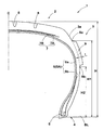
図1は、本実施形態の正規状態の空気入りタイヤ(以下、単に「タイヤ」ということがある。)1の断面図である。前記「正規状態」は、タイヤ1が正規リムRにリム組みされ、かつ、正規内圧が充填された無負荷の状態である。本明細書では、特に断りがない限り、タイヤ1の各部の寸法は、正規状態で測定された値である。
Hereinafter, an embodiment of the present invention will be described with reference to the drawings.
FIG. 1 is a cross-sectional view of a pneumatic tire (hereinafter simply referred to as “tire”) 1 in a normal state according to this embodiment. The “normal state” is a no-load state in which the tire 1 is assembled on the normal rim R and filled with the normal internal pressure. In this specification, unless otherwise specified, the dimensions of each part of the tire 1 are values measured in a normal state.
前記「正規リム」Rとは、タイヤ1が基づいている規格を含む規格体系において、当該規格がタイヤ毎に定めるリムであり、例えばJATMAであれば "標準リム" 、TRAであれば "Design Rim" 、ETRTOであれば "Measuring Rim" である。 The “regular rim” R is a rim determined for each tire in the standard system including the standard on which the tire 1 is based. For example, “Standard Rim” for JATMA, “Design Rim” for TRA. "If it is ETRTO, it is" Measuring Rim ".
前記「正規内圧」とは、タイヤ1が基づいている規格を含む規格体系において、各規格がタイヤ毎に定めている空気圧であり、JATMAであれば "最高空気圧" 、TRAであれば表 "TIRE LOAD LIMITS AT VARIOUS COLD INFLATION PRESSURES" に記載の最大値、ETRTOであれば "INFLATION PRESSURE" である。 以下、本発明の実施の一形態が図面に基づき説明される。 The “regular internal pressure” is the air pressure defined by each standard for each tire in the standard system including the standard on which the tire 1 is based, and is “maximum air pressure” for JATMA, and “TIRE” for TRA. The maximum value described in “LOAD LIMITS AT VARIOUS COLD INFLATION PRESSURES”, “INFLATION PRESSURE” in the case of ETRTO. Hereinafter, an embodiment of the present invention will be described with reference to the drawings.
図1に示されるように、本実施形態のタイヤ1は、トレッド部2からサイドウォール部3を経てビード部4のビードコア5に至るカーカス6と、このカーカス6の半径方向外側かつトレッド部2の内部に配されるベルト層7とを備えている。なお、トレッド部2には、適宜排水用又は排泥用の溝8が設けられている。
As shown in FIG. 1, the tire 1 of the present embodiment includes a
カーカス6は、1枚以上、本実施形態では1枚のカーカスプライ6Aからなる。カーカスプライ6Aは、カーカスコードの層であって、例えば、本体部6aと折り返し部6bとを含んでいる。本体部6aは、一対のビード部4,4間を、トロイド状にのびている。折り返し部6bは、本体部6aに連なりビードコア5の周囲を、タイヤ軸方向の内側から外側に折り返されている。
The
上述のカーカスコードは、例えば、タイヤ赤道Cに対して例えば75〜90°の角度で配列されている。カーカスコードには、例えば、ナイロン、ポリエステル、レーヨン等の有機繊維コードが好適に使用される。 The carcass cords described above are arranged at an angle of, for example, 75 to 90 ° with respect to the tire equator C. For the carcass cord, for example, an organic fiber cord such as nylon, polyester, or rayon is preferably used.
ベルト層7は、例えば、ベルトコードをタイヤ赤道Cに対して、15〜35°以下の角度で配列された少なくとも2枚、本実施形態では2枚のベルトプライ7A,7Bからなる。2枚のベルトプライ7A,7Bは、例えば、前記ベルトコードが互いに交差する向きに重ね合わせて構成される。前記ベルトコードとしては、高弾性コード、とりわけスチールコードが望ましい。
The belt layer 7 includes, for example, at least two
本実施形態のタイヤ1は、少なくとも一方のサイドウォール部3の外面3aに、タイヤ軸方向外側に隆起するプロテクタ9を有している。プロテクタ9は、例えば、ゴムで形成され、本実施形態では、両方のサイドウォール部3にそれぞれ設けられている。
The tire 1 of this embodiment has a
プロテクタ9は、ビードベースラインBLからタイヤ断面高さHの0.5〜0.9倍の範囲内の位置に設けられるのが望ましい。ここで、タイヤ断面高さHは、ビードベースラインBLから、タイヤ赤道Cにおけるトレッド部2の接地面までの距離である。このようなプロテクタ9は、サイドウォール部3の耐カット性能を向上させることができる。
The
より好ましい態様として、プロテクタ9のタイヤ半径方向の外端9aのビードベースラインBLからの高さH1は、タイヤ断面高さHの0.75〜0.85倍である。プロテクタ9の外端9aのビードベースラインBLからの高さH1が、タイヤ断面高さHの0.85倍を超えると、プロテクタ9の外端9aが泥濘地のような悪路以外の路面でも容易に接触し、乗り心地の悪化やプロテクタ9の早期摩耗が生じるおそれがある。逆に、高さH1がタイヤ断面高さHの0.75倍未満であると、カット傷が生じやすい領域の保護ができず、耐カット性能が向上しないおそれがある。
As a more preferable aspect, the height H1 of the
また、プロテクタ9のタイヤ半径方向の内端9bのビードベースラインBLからの高さH2は、タイヤ断面高さHの0.5〜0.6倍であるのが好ましい。プロテクタ9の内端9bのビードベースラインBLからの高さH2がタイヤ断面高さHの0.6倍を超えると、プロテクタ9による保護領域が小さくなり、耐カット性能が向上しないおそれがある。逆に、高さH2がタイヤ断面高さHの0.5倍未満であると、プロテクタ9が過剰に大きくなり、タイヤ重量の増加を招くとともに、蓄熱し易くなるおそれがある。
The height H2 of the
プロテクタ9の隆起厚さtは、好ましくは2mm以上、より好ましくは4mm以上である。隆起厚さtが小さくなると、サイドウォール部3の保護効果が低下するため耐カット性能が向上しないおそれがある。逆に、隆起厚さtが大きくなると、タイヤ重量が増加するとともに、蓄熱し易くなるので、プロテクタ9の隆起厚さLは、好ましくは15mm以下、より好ましくは12mm以下である。
The raised thickness t of the
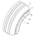
図2は、プロテクタ9の斜視図である。図2に示されるように、本実施形態のプロテクタ9は、複数の単位隆起模様9Aがタイヤ周方向に離間して配されている。本実施形態では、各単位隆起模様9Aは、同一の形状を有し、同一の向きで配されている。各単位隆起模様9Aは、タイヤ半径方向の略同一の高さに位置するのが望ましい。
FIG. 2 is a perspective view of the
このようなプロテクタ9は、単位隆起模様9A間に隆起しない部位を設けることができるので、耐カット性能を維持しつつ空隙率を高くすることができ、サイドウォール部3が、蓄熱しにくくなる。また、単位隆起模様9Aと隆起しない部位との凹凸構造は、タイヤ走行時に周囲の空気をかき乱して乱流を発生させることができるので、サイドウォール部3の放熱性を向上させることができる。その結果、サイドウォール部3は、温度上昇が抑制され、タイヤ1の耐久性が向上する。
Since such a
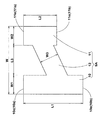
図3は、単位隆起模様9Aの側面図である。図3に示されるように、本実施形態の各単位隆起模様9Aは、タイヤ半径方向にのびる第1突部10及び第2突部11を含んでいる。第1突部10と第2突部11とは、タイヤ周方向に離間して配されている。
FIG. 3 is a side view of the unit raised
第1突部10は、例えば、所定のタイヤ半径方向長さL1とタイヤ周方向長さW1とを有する略矩形状である。第1突部10のタイヤ半径方向長さL1は、第1突部10のタイヤ周方向長さW1よりも大きい縦長形状であるのが望ましい。
For example, the
第1突部10のタイヤ周方向長さW1は、好ましくは、単位隆起模様9Aのタイヤ周方向長さWの0.15〜0.3倍である。第1突部10のタイヤ周方向長さW1が単位隆起模様9Aのタイヤ周方向長さWの0.15倍未満であると、サイドウォール部3の保護効果が低下するため耐カット性能が向上しないおそれがある。逆に、第1突部10のタイヤ周方向長さW1が単位隆起模様9Aのタイヤ周方向長さWの0.3倍より大きくなると、タイヤ重量が増加するとともに、蓄熱し易くなるおそれがある。
The tire circumferential direction length W1 of the
第2突部11は、例えば、所定のタイヤ半径方向長さL2とタイヤ周方向長さW2とを有する略矩形状である。第2突部11のタイヤ半径方向長さL2は、第2突部11のタイヤ周方向長さW2よりも大きいのが望ましい。
The
第2突部11のタイヤ周方向長さW2は、好ましくは、単位隆起模様9Aのタイヤ周方向長さWの0.15〜0.3倍である。第2突部11のタイヤ周方向長さW2が単位隆起模様9Aのタイヤ周方向長さWの0.15倍未満であると、サイドウォール部3の保護効果が低下するため耐カット性能が向上しないおそれがある。逆に、第2突部11のタイヤ周方向長さW2が単位隆起模様9Aのタイヤ周方向長さWの0.3倍より大きくなると、タイヤ重量が増加するとともに、蓄熱し易くなるおそれがある。
The tire circumferential direction length W2 of the
本実施形態では、第1突部10のタイヤ半径方向長さL1は、第2突部11のタイヤ半径方向長さL2よりも大きい。このような第1突部10及び第2突部11を含む単位隆起模様9Aは、第1突部10と第2突部11とのタイヤ半径方向長さL1,L2の差により、タイヤ走行時に渦流を発生させることができる。その結果、サイドウォール部3は、より優れた放熱性を発揮し、タイヤ1の耐久性をより向上させることができる。
In the present embodiment, the length L1 of the
第1突部10は、例えば、第1突部10のタイヤ半径方向長さL1を既定する1対のタイヤ半径方向の端部10eを有している。第1突部10の端部10eは、タイヤ半径方向外側の外端10aとタイヤ半径方向内側の内端10bとを含んでいる。また、第2突部11は、例えば、第2突部11のタイヤ半径方向長さL2を既定する1対のタイヤ半径方向の端部11eを有している。第2突部11の端部11eは、タイヤ半径方向外側の外端11aとタイヤ半径方向内側の内端11bとを含んでいる。
The
第1突部10のタイヤ半径方向の外端10aの高さは、第2突部11のタイヤ半径方向の外端11aの高さに略等しいのが望ましい。この場合、第2突部11の内端11bの高さが、第1突部10の内端10bの高さよりも、タイヤ半径方向の外側に位置する。このため、第2突部11の内端11bのタイヤ半径方向の内側に、広範囲の隆起しない部位を設けることができるので、タイヤ走行時により大きな渦流を発生させることができる。
The height of the
第1突部10のタイヤ周方向長さW1は、第2突部11のタイヤ周方向長さW2に略等しいのが望ましい。このような第1突部10及び第2突部11を含む単位隆起模様9Aは、タイヤ周方向の剛性の不均衡が抑制され、乗り心地の悪化が抑制されるとともに、タイヤ1の偏摩耗を抑制することができる。
It is desirable that the tire circumferential direction length W1 of the
第1突部10と第2突部11とのタイヤ周方向の離間距離L3は、第1突部10のタイヤ周方向長さW1及び第2突部11のタイヤ周方向長さW2よりも大きいのが望ましい。離間距離L3を大きくすることで、サイドウォール部3は、より蓄熱しにくい構造にすることができる。
The separation distance L3 in the tire circumferential direction between the
本実施形態の各単位隆起模様9Aは、さらに、第1突部10及び第2突部11をタイヤ周方向に連結する第3突部12を含んでいる。このような単位隆起模様9Aは、第3突部12によりタイヤ周方向の剛性を向上させることができる。このため、第3突部12は、タイヤ1のトレッド端の動きを抑制し、トレッド部2の耐偏摩耗性能を向上させ、その結果、タイヤ1の耐久性を向上させ得る。
Each unit raised
第3突部12は、第1突部10のタイヤ半径方向の端部10eからタイヤ半径方向に離れた位置に連結されるのが望ましい。このため、第1突部10は、タイヤ走行時に端部10e付近で乱流が発生し易く、サイドウォール部3の放熱性をより向上させることができる。
The
第3突部12は、第2突部11のタイヤ半径方向の端部11eからタイヤ半径方向に離れた位置に連結されるのが望ましい。このため、第2突部11は、タイヤ走行時に端部11e付近で乱流が発生し易く、サイドウォール部3の放熱性をより向上させることができる。
The
第3突部12は、第1突部10のタイヤ半径方向の内端10b側に連結されるとともに、第2突部11のタイヤ半径方向の内端11b側に連結されるのが望ましい。このため、第1突部10及び第2突部11のタイヤ半径方向の外端10a,11a側は、例えば、タイヤ1が泥濘地を走行する時に、泥等と接触し、駆動力を伝達することができる。
The
第3突部12は、タイヤ周方向に対して傾斜しているのが望ましい。このような第3突部12は、サイドウォール部3のタイヤ周方向の剛性を向上させるとともに、タイヤ半径方向の剛性も向上させることができる。
The
第3突部12の長手方向に直交する長さW3は、第1突部10のタイヤ周方向長さW1又は第2突部11のタイヤ周方向長さW2と略等しいのが望ましい。このため、第1突部10、第2突部11及び第3突部12を含む単位隆起模様9Aは、局所的な剛性の不均衡が抑制され、乗り心地の悪化が抑制されるとともに、タイヤ1の偏摩耗を抑制することができる。
The length W3 orthogonal to the longitudinal direction of the
第1突部10のタイヤ半径方向長さL1と単位隆起模様9Aのタイヤ周方向長さWとで既定される略矩形状の単位隆起模様領域において、第1突部10、第2突部11及び第3突部12の占める割合は、40%〜60%であるのが好ましい。当該割合が40%未満であると、サイドウォール部3の保護効果が低下するため耐カット性能が向上しないおそれがある。逆に、当該割合が60%より大きくなると、タイヤ重量が増加するとともに、蓄熱し易くなるおそれがある。
In the substantially rectangular unit raised pattern area defined by the tire radial direction length L1 of the first protruding
以上、本発明の特に好ましい実施形態について詳述したが、本発明は、上記実施形態に限定されることなく、種々の態様に変形して実施し得る。 As mentioned above, although especially preferable embodiment of this invention was explained in full detail, this invention is not limited to the said embodiment, It can deform | transform and implement in a various aspect.
図1の基本構造を有し、かつ表1の仕様のプロテクタを有する空気入りタイヤ(サイズ:265/70R17)が製造され、それらの耐カット性能、放熱性及び耐偏摩耗性能がテストされた。
テスト方法は、次の通りである。
Pneumatic tires (size: 265 / 70R17) having the basic structure shown in FIG. 1 and the protectors having the specifications shown in Table 1 were manufactured, and their cut resistance, heat dissipation, and uneven wear resistance were tested.
The test method is as follows.
<耐カット性能>
テストタイヤを全輪に装着した四輪駆動車にて、瓦礫等が散乱する悪路をドライバー1名乗車で約1500km走行したときのサイドウォール部に生じたカット傷(長さ×深さ)の合計値が測定された。結果は、比較例1の値の逆数を100とする指数で表示され、数値が大きいほど耐カット性能に優れることを示す。
<Cut resistance>
Cut scratches (length x depth) that occurred on the side wall of a four-wheel drive vehicle with test tires mounted on all wheels when traveling about 1,500 km on a rough road where rubble, etc. scatters. The total value was measured. A result is displayed by the index | exponent which makes the reciprocal number of the value of the comparative example 1 100, and it shows that it is excellent in cut-proof performance, so that a numerical value is large.
<放熱性>
テストタイヤを台上試験機にセットし、100km/hで24時間走行させたときのサイドウォール部の温度が測定された。結果は、比較例1の値の逆数を100とする指数であり、数値が大きいほど蓄熱しにくく放熱性に優れることを示す。
<Heat dissipation>
The temperature of the sidewall was measured when the test tire was set on a bench test machine and run at 100 km / h for 24 hours. A result is an index | exponent which makes the reciprocal number of the value of the comparative example 1 100, and shows that it is hard to accumulate heat and is excellent in heat dissipation, so that a numerical value is large.
<耐偏摩耗性能>
テストタイヤを台上試験機にセットし、100km/hで24時間走行させたときのトレッド部の摩耗量のバラつきが測定された。結果は、比較例1の値の逆数を100とする指数であり、数値が大きいほど耐偏摩耗性能に優れることを示す。
テストの結果を表1に示す。
<Uneven wear resistance>
When the test tire was set on a bench test machine and run at 100 km / h for 24 hours, the variation in wear amount of the tread portion was measured. A result is an index | exponent which makes the reciprocal number of the value of the comparative example 1 100, and shows that it is excellent in uneven wear-proof performance, so that a numerical value is large.
The test results are shown in Table 1.

テストの結果、実施例のタイヤは、比較例に比べて同等の耐カット性能を維持しつつ、放熱性と耐偏摩耗性能とを向上していることが確認された。 As a result of the test, it was confirmed that the tires of the examples improved heat dissipation and uneven wear resistance while maintaining equivalent cut resistance performance compared to the comparative example.
1 空気入りタイヤ
3 サイドウォール部
3a サイドウォール部の外面
9 プロテクタ
9A 単位隆起模様
10 第1突部
11 第2突部
12 第3突部
DESCRIPTION OF SYMBOLS 1
Claims (8)
前記プロテクタは、複数の単位隆起模様がタイヤ周方向に離間して配されており、
前記各単位隆起模様は、タイヤ周方向に離間して配されかつタイヤ半径方向にのびる第1突部及び第2突部と、前記第1突部及び前記第2突部をタイヤ周方向に連結する第3突部とを含み、
前記第1突部のタイヤ半径方向長さは、前記第2突部のタイヤ半径方向長さよりも大きいことを特徴とする空気入りタイヤ。 A pneumatic tire having a protector that protrudes outward in the tire axial direction on the outer surface of at least one sidewall portion,
The protector is provided with a plurality of unit raised patterns spaced apart in the tire circumferential direction,
Each unit raised pattern is spaced apart in the tire circumferential direction and extends in the tire radial direction, and connects the first and second protrusions in the tire circumferential direction. And a third protrusion that
A pneumatic tire characterized in that a length of the first protrusion in the tire radial direction is larger than a length of the second protrusion in the tire radial direction.
Priority Applications (4)
| Application Number | Priority Date | Filing Date | Title |
|---|---|---|---|
| JP2016009929A JP6699192B2 (en) | 2016-01-21 | 2016-01-21 | Pneumatic tire |
| CN201611235420.3A CN107020895B (en) | 2016-01-21 | 2016-12-28 | Pneumatic tire |
| EP17151298.1A EP3196054B1 (en) | 2016-01-21 | 2017-01-13 | Pneumatic tire |
| US15/409,668 US10427473B2 (en) | 2016-01-21 | 2017-01-19 | Pneumatic tire |
Applications Claiming Priority (1)
| Application Number | Priority Date | Filing Date | Title |
|---|---|---|---|
| JP2016009929A JP6699192B2 (en) | 2016-01-21 | 2016-01-21 | Pneumatic tire |
Publications (2)
| Publication Number | Publication Date |
|---|---|
| JP2017128267A true JP2017128267A (en) | 2017-07-27 |
| JP6699192B2 JP6699192B2 (en) | 2020-05-27 |
Family
ID=57796224
Family Applications (1)
| Application Number | Title | Priority Date | Filing Date |
|---|---|---|---|
| JP2016009929A Active JP6699192B2 (en) | 2016-01-21 | 2016-01-21 | Pneumatic tire |
Country Status (4)
| Country | Link |
|---|---|
| US (1) | US10427473B2 (en) |
| EP (1) | EP3196054B1 (en) |
| JP (1) | JP6699192B2 (en) |
| CN (1) | CN107020895B (en) |
Cited By (4)
| Publication number | Priority date | Publication date | Assignee | Title |
|---|---|---|---|---|
| JP2019048502A (en) * | 2017-09-08 | 2019-03-28 | Toyo Tire株式会社 | Pneumatic tire |
| JP2020001658A (en) * | 2018-07-02 | 2020-01-09 | 横浜ゴム株式会社 | Pneumatic tire |
| EP3613613A1 (en) | 2018-08-21 | 2020-02-26 | Sumitomo Rubber Industries, Ltd. | Pneumatic tire |
| US11633992B2 (en) | 2020-07-17 | 2023-04-25 | Toyo Tire Corporation | Tire |
Families Citing this family (10)
| Publication number | Priority date | Publication date | Assignee | Title |
|---|---|---|---|---|
| JP6686446B2 (en) * | 2016-01-07 | 2020-04-22 | 住友ゴム工業株式会社 | Pneumatic tire |
| JP6728801B2 (en) * | 2016-03-14 | 2020-07-22 | 住友ゴム工業株式会社 | Pneumatic tire |
| JP6898176B2 (en) * | 2017-08-17 | 2021-07-07 | Toyo Tire株式会社 | Pneumatic tires |
| JP7095244B2 (en) * | 2017-09-21 | 2022-07-05 | 住友ゴム工業株式会社 | Pneumatic tires |
| JP6890086B2 (en) * | 2017-12-12 | 2021-06-18 | 株式会社ブリヂストン | Heavy load tires |
| JP7119634B2 (en) * | 2018-06-21 | 2022-08-17 | 住友ゴム工業株式会社 | pneumatic tire |
| JP7091942B2 (en) * | 2018-08-28 | 2022-06-28 | 住友ゴム工業株式会社 | Pneumatic tires |
| JP2021095109A (en) * | 2019-12-19 | 2021-06-24 | 住友ゴム工業株式会社 | Pneumatic tire |
| JP7443764B2 (en) * | 2019-12-25 | 2024-03-06 | 住友ゴム工業株式会社 | pneumatic tires |
| CN114312163B (en) * | 2020-09-30 | 2024-01-02 | 通伊欧轮胎株式会社 | Tire with a tire body |
Citations (7)
| Publication number | Priority date | Publication date | Assignee | Title |
|---|---|---|---|---|
| JP2009029383A (en) * | 2007-07-30 | 2009-02-12 | Bridgestone Corp | Pneumatic tire |
| JP2009149181A (en) * | 2007-12-20 | 2009-07-09 | Toyo Tire & Rubber Co Ltd | Pneumatic tire |
| JP2010264962A (en) * | 2009-05-18 | 2010-11-25 | Toyo Tire & Rubber Co Ltd | Pneumatic tire |
| JP2012166605A (en) * | 2011-02-10 | 2012-09-06 | Toyo Tire & Rubber Co Ltd | Pneumatic tire and method for manufacturing the same |
| JP2012179964A (en) * | 2011-02-28 | 2012-09-20 | Sumitomo Rubber Ind Ltd | Pneumatic tire |
| EP2711202A1 (en) * | 2012-09-21 | 2014-03-26 | Continental Reifen Deutschland GmbH | Pneumatic tyres for a vehicle |
| WO2016121874A1 (en) * | 2015-01-29 | 2016-08-04 | 横浜ゴム株式会社 | Pneumatic tire |
Family Cites Families (14)
| Publication number | Priority date | Publication date | Assignee | Title |
|---|---|---|---|---|
| JPS5442705A (en) * | 1977-09-07 | 1979-04-04 | Bridgestone Corp | Pneumatic tyre having protective ribs on both side walls |
| US6938657B1 (en) * | 1999-08-05 | 2005-09-06 | Pirelli Pneumatici S.P.A. | Tire for a vehicle wheel capable of withstanding the load at low pressure or zero pressure |
| US20040007303A1 (en) * | 2002-07-10 | 2004-01-15 | Jordan Fishman | Tire with enhanced sidewall |
| JP5374362B2 (en) * | 2007-03-12 | 2013-12-25 | 株式会社ブリヂストン | Pneumatic tire |
| JP5081477B2 (en) * | 2007-03-12 | 2012-11-28 | 株式会社ブリヂストン | Pneumatic tire |
| EP2287017B1 (en) * | 2008-05-20 | 2014-01-22 | Bridgestone Corporation | Pneumatic tire |
| JP5160345B2 (en) * | 2008-08-26 | 2013-03-13 | 東洋ゴム工業株式会社 | Pneumatic tire |
| ES2562638T3 (en) * | 2009-04-28 | 2016-03-07 | Bridgestone Corporation | Tire |
| JP5452388B2 (en) | 2010-06-23 | 2014-03-26 | 住友ゴム工業株式会社 | Pneumatic tire |
| JP5066240B2 (en) * | 2010-09-24 | 2012-11-07 | 住友ゴム工業株式会社 | Pneumatic tire |
| JP5391243B2 (en) * | 2011-07-29 | 2014-01-15 | 住友ゴム工業株式会社 | Pneumatic tire |
| JP5391249B2 (en) * | 2011-09-15 | 2014-01-15 | 住友ゴム工業株式会社 | Pneumatic tire |
| JP6778557B2 (en) * | 2016-09-07 | 2020-11-04 | Toyo Tire株式会社 | Pneumatic tires |
| JP6774307B2 (en) * | 2016-11-09 | 2020-10-21 | Toyo Tire株式会社 | Pneumatic tires |
-
2016
- 2016-01-21 JP JP2016009929A patent/JP6699192B2/en active Active
- 2016-12-28 CN CN201611235420.3A patent/CN107020895B/en active Active
-
2017
- 2017-01-13 EP EP17151298.1A patent/EP3196054B1/en active Active
- 2017-01-19 US US15/409,668 patent/US10427473B2/en active Active
Patent Citations (7)
| Publication number | Priority date | Publication date | Assignee | Title |
|---|---|---|---|---|
| JP2009029383A (en) * | 2007-07-30 | 2009-02-12 | Bridgestone Corp | Pneumatic tire |
| JP2009149181A (en) * | 2007-12-20 | 2009-07-09 | Toyo Tire & Rubber Co Ltd | Pneumatic tire |
| JP2010264962A (en) * | 2009-05-18 | 2010-11-25 | Toyo Tire & Rubber Co Ltd | Pneumatic tire |
| JP2012166605A (en) * | 2011-02-10 | 2012-09-06 | Toyo Tire & Rubber Co Ltd | Pneumatic tire and method for manufacturing the same |
| JP2012179964A (en) * | 2011-02-28 | 2012-09-20 | Sumitomo Rubber Ind Ltd | Pneumatic tire |
| EP2711202A1 (en) * | 2012-09-21 | 2014-03-26 | Continental Reifen Deutschland GmbH | Pneumatic tyres for a vehicle |
| WO2016121874A1 (en) * | 2015-01-29 | 2016-08-04 | 横浜ゴム株式会社 | Pneumatic tire |
Cited By (7)
| Publication number | Priority date | Publication date | Assignee | Title |
|---|---|---|---|---|
| JP2019048502A (en) * | 2017-09-08 | 2019-03-28 | Toyo Tire株式会社 | Pneumatic tire |
| JP2020001658A (en) * | 2018-07-02 | 2020-01-09 | 横浜ゴム株式会社 | Pneumatic tire |
| WO2020008699A1 (en) * | 2018-07-02 | 2020-01-09 | 横浜ゴム株式会社 | Pneumatic tire |
| JP7115074B2 (en) | 2018-07-02 | 2022-08-09 | 横浜ゴム株式会社 | pneumatic tire |
| EP3613613A1 (en) | 2018-08-21 | 2020-02-26 | Sumitomo Rubber Industries, Ltd. | Pneumatic tire |
| US11667160B2 (en) | 2018-08-21 | 2023-06-06 | Sumitomo Rubber Industries, Ltd. | Pneumatic tire |
| US11633992B2 (en) | 2020-07-17 | 2023-04-25 | Toyo Tire Corporation | Tire |
Also Published As
| Publication number | Publication date |
|---|---|
| JP6699192B2 (en) | 2020-05-27 |
| EP3196054A1 (en) | 2017-07-26 |
| CN107020895B (en) | 2020-10-27 |
| EP3196054B1 (en) | 2019-12-04 |
| US10427473B2 (en) | 2019-10-01 |
| CN107020895A (en) | 2017-08-08 |
| US20170210182A1 (en) | 2017-07-27 |
Similar Documents
| Publication | Publication Date | Title |
|---|---|---|
| JP2017128267A (en) | Pneumatic tire | |
| JP5457484B2 (en) | Heavy duty pneumatic tire | |
| JP2017170937A (en) | Pneumatic tire | |
| JP6867115B2 (en) | Pneumatic tires | |
| JP6728801B2 (en) | Pneumatic tire | |
| JP2017121876A (en) | Pneumatic tire | |
| JP7095244B2 (en) | Pneumatic tires | |
| JP6450320B2 (en) | Pneumatic tire | |
| JP2018095042A (en) | Pneumatic tire | |
| JP2007076594A (en) | Pneumatic tire | |
| JP2018095185A (en) | Pneumatic tire | |
| JP6013759B2 (en) | Pneumatic tire | |
| JP6214443B2 (en) | Pneumatic tire | |
| JP6624231B2 (en) | Pneumatic tire | |
| JP6245003B2 (en) | Pneumatic tire | |
| JP5405992B2 (en) | Heavy duty pneumatic radial tire | |
| JP4380871B2 (en) | Heavy duty radial tire | |
| JP2016196218A (en) | Pneumatic tire | |
| JP2016002983A (en) | Pneumatic tire | |
| JP6141178B2 (en) | Pneumatic tire | |
| JP2013063676A (en) | Pneumatic tire | |
| JP6186756B2 (en) | Pneumatic tire | |
| JP5453157B2 (en) | Pneumatic tire | |
| JP7155806B2 (en) | pneumatic tire | |
| JP2018058535A (en) | Pneumatic tire |
Legal Events
| Date | Code | Title | Description |
|---|---|---|---|
| A621 | Written request for application examination |
Free format text: JAPANESE INTERMEDIATE CODE: A621 Effective date: 20181102 |
|
| A131 | Notification of reasons for refusal |
Free format text: JAPANESE INTERMEDIATE CODE: A131 Effective date: 20190827 |
|
| A977 | Report on retrieval |
Free format text: JAPANESE INTERMEDIATE CODE: A971007 Effective date: 20190830 |
|
| A521 | Request for written amendment filed |
Free format text: JAPANESE INTERMEDIATE CODE: A523 Effective date: 20191002 |
|
| TRDD | Decision of grant or rejection written | ||
| A01 | Written decision to grant a patent or to grant a registration (utility model) |
Free format text: JAPANESE INTERMEDIATE CODE: A01 Effective date: 20200331 |
|
| A61 | First payment of annual fees (during grant procedure) |
Free format text: JAPANESE INTERMEDIATE CODE: A61 Effective date: 20200413 |
|
| R150 | Certificate of patent or registration of utility model |
Ref document number: 6699192 Country of ref document: JP Free format text: JAPANESE INTERMEDIATE CODE: R150 |
|
| R250 | Receipt of annual fees |
Free format text: JAPANESE INTERMEDIATE CODE: R250 |