JP2017123786A - Humidification bag and incubator with humidification bag - Google Patents
Humidification bag and incubator with humidification bag Download PDFInfo
- Publication number
- JP2017123786A JP2017123786A JP2016003263A JP2016003263A JP2017123786A JP 2017123786 A JP2017123786 A JP 2017123786A JP 2016003263 A JP2016003263 A JP 2016003263A JP 2016003263 A JP2016003263 A JP 2016003263A JP 2017123786 A JP2017123786 A JP 2017123786A
- Authority
- JP
- Japan
- Prior art keywords
- bag
- humidifying
- gas
- gas permeable
- liquid
- Prior art date
- Legal status (The legal status is an assumption and is not a legal conclusion. Google has not performed a legal analysis and makes no representation as to the accuracy of the status listed.)
- Granted
Links
Images


Landscapes
- Apparatus Associated With Microorganisms And Enzymes (AREA)
Abstract
【課題】培養室のような装置の内部で水のような液体の零れを全く無くすことで取り扱いやすく、装置の内部を容易に加湿することができる加湿用バッグおよび加湿用バッグを備えるインキュベータを提供する。【解決手段】加湿用バッグ1(1S)は、装置の内部を加湿するための加湿用バッグであり、開口部4を有し、液体(例えば滅菌水W)を封入するためのバッグ本体2と、バック本体2の開口部4を閉じるようにバッグ本体2に配置されて、バッグ本体2内の液体は通さずに液体のガス(例えば水蒸気)を通して装置の内部を加湿するガス透過性部材3と、ガス透過性部材3を覆うことで、ガス透過性部材3からガスがバッグ本体2の外に出るのを防ぎ、装置の内部を加湿する際には外して、ガス透過性部材3を露出させるガス透過防止シート5を備える。【選択図】図6PROBLEM TO BE SOLVED: To provide an incubator including a humidifying bag and a humidifying bag which are easy to handle by completely eliminating spillage of a liquid such as water inside an apparatus such as a culture chamber and can easily humidify the inside of the apparatus. do. A humidifying bag 1 (1S) is a humidifying bag for humidifying the inside of an apparatus, has an opening 4, and has a bag main body 2 for enclosing a liquid (for example, sterile water W). A gas permeable member 3 arranged in the bag body 2 so as to close the opening 4 of the back body 2 and humidifying the inside of the device through a liquid gas (for example, water vapor) without passing the liquid in the bag body 2. By covering the gas permeable member 3, gas is prevented from coming out of the bag body 2 from the gas permeable member 3, and when the inside of the device is humidified, it is removed to expose the gas permeable member 3. A gas permeation prevention sheet 5 is provided. [Selection diagram] Fig. 6
Description
本発明は、細胞等の培養物を培養するための装置である例えばインキュベータの培養室内に配置されて、培養環境を加湿する加湿用バッグおよび加湿用バッグを備えるインキュベータに関する。 The present invention relates to an incubator provided with a humidifying bag and a humidifying bag that are arranged in a culture chamber of an incubator, for example, an apparatus for culturing a culture of cells and the like, and humidify a culture environment.
培養物を培養するための装置である例えばインキュベータは、人間の細胞または動物の細胞等の培養物を培養するのに用いられる。インキュベータの例として、培養室内に二酸化炭素(CO2)ガスを供給するCO2インキュベータが、特許文献1に開示されている。
An incubator, which is an apparatus for culturing a culture, is used for culturing a culture such as human cells or animal cells. As an example of the incubator,
CO2インキュベータの培養室内では、培養物を培養するために、90%以上の湿度環境が必要である。培養室内で90%以上の湿度環境を得るために、通常、上蓋の無いトレイ式の加湿バットを用意して、この加湿バットに水を入れて、水の入った加湿バットをCO2インキュベータの培養室内に入れる。これにより、培養室内は、水蒸気の発生により加湿して、90%以上の湿度環境を得ることができる。 In the culture chamber of the CO2 incubator, a humidity environment of 90% or more is necessary for culturing the culture. In order to obtain a humidity environment of 90% or higher in the culture chamber, a tray-type humidified bat without a top cover is usually prepared, and water is put into the humidified bat. Put in. Thereby, the inside of a culture room can be humidified by generation | occurrence | production of water vapor | steam, and a 90% or more humidity environment can be obtained.
ところで、作業者が、上蓋の無いトレイ式の加湿バットに水を入れた状態で加湿バットを運ぶと、加湿バット内から水が零れ易いので、取り扱いが難しい。また、水の入った加湿バットを培養室内に入れた状態では、例えば地震等の外力がCO2インキュベータに加わった時に、加湿バットから培養室内で水が零れてしまう等の問題がある。 By the way, when an operator carries a humidifying bat in a state where water is put in a tray-type humidifying bat without an upper lid, it is difficult to handle because water easily spills from the humidifying bat. In addition, when a humidified bat containing water is placed in the culture chamber, there is a problem that when an external force such as an earthquake is applied to the CO2 incubator, water spills from the humidified bat into the culture chamber.
本発明は、上記に鑑みてなされたもので、その目的とするところは、培養室のような装置の内部で水のような液体の零れを全く無くすことで取り扱いやすく、装置の内部を容易に加湿することができる加湿用バッグおよび加湿用バッグを備えるインキュベータを提供することにある。 The present invention has been made in view of the above, and an object of the present invention is to make it easy to handle by eliminating the spillage of liquid such as water inside the apparatus such as a culture chamber, and to easily make the inside of the apparatus easy. An object of the present invention is to provide a humidifying bag that can be humidified and an incubator including the humidifying bag.
上記課題を達成するため、請求項1に記載の加湿用バッグは、装置の内部を加湿するための加湿用バッグであって、開口部を有し、液体を封入するためのバッグ本体と、前記バック本体の前記開口部を閉じるように前記バッグ本体に配置されて、前記バッグ本体内の前記液体は通さずに前記液体のガスを通して前記装置の内部を加湿するガス透過性部材と、前記ガス透過性部材を覆うことで、前記ガス透過性部材から前記ガスが前記バッグ本体の外に出るのを防ぎ、前記装置の内部を加湿する際には外して、前記ガス透過性部材を露出させるガス透過防止シートと、を備えることを特徴とする。
In order to achieve the above object, the humidifying bag according to
請求項1に記載の加湿用バッグでは、バッグ本体が液体を封入した状態では、ガス透過性部材は液体を通さずないので、液体が開口部から漏れることは無い。しかも、ガス透過防止シートは、ガス透過性部材から液体のガスが漏れるのを防ぐことができる。 In the humidifying bag according to the first aspect, in a state where the bag main body encloses the liquid, the gas permeable member does not allow the liquid to pass therethrough, so that the liquid does not leak from the opening. Moreover, the gas permeation prevention sheet can prevent liquid gas from leaking from the gas permeable member.
このため、加湿用バッグは、装置の内部で、水のような液体が零れることを全く無くすことで取扱いが容易になり、ガス透過防止シートを取り除けば、ガス透過性部材から液体のガスが漏れるので、その液体のガスにより装置の内部を容易に加湿することができる。 For this reason, the humidifying bag is easy to handle by eliminating the spilling of liquid such as water inside the device, and if the gas permeation prevention sheet is removed, the liquid gas leaks from the gas permeable member. Therefore, the inside of the apparatus can be easily humidified by the liquid gas.
請求項2に記載の加湿用バッグでは、前記ガス透過防止シート上に粘着され、前記加湿する際には剥がすことで、前記ガス透過防止シートを前記ガス透過性部材から取り除くための被覆シートを有していることを特徴とする。
The humidifying bag according to
請求項2に記載の加湿用バッグでは、装置の内部を加湿する際には、被覆シートを剥がすことで、被覆シートとともにガス透過防止シートを、簡単にしかも確実にガス透過性部材から取り除くことができる。
In the humidifying bag according to
請求項3に記載の加湿用バッグでは、前記ガス透過防止シートは、切り込み部分を有し、前記切り込み部分は、前記被覆シートを剥がす際に前記ガス透過性部材から取り除かれる剥離部分と、前記バッグ本体側に残る残存部分と、を分けていることを特徴とする。
4. The humidifying bag according to
請求項3に記載の加湿用バッグでは、装置の内部を加湿する際には、被覆シートを剥がすことで、被覆シートとともにガス透過防止シートの剥離部分だけをガス透過性部材から、簡単にしかも確実に取り除くことができる。
In the humidifying bag according to
請求項4に記載の加湿用バッグでは、前記バッグ本体は、前記液体を注入するための注入部を有することを特徴とする。
In the humidifying bag according to
請求項4に記載の加湿用バッグでは、作業者が、装置の内部を加湿する際に、加湿用バッグ内に後から、加湿に必要する任意の液体を注入することができる。 In the humidifying bag according to the fourth aspect, when the inside of the apparatus is humidified, the operator can inject any liquid necessary for humidification later into the humidifying bag.
請求項5に記載の加湿用バッグを備えたインキュベータは、内部を所定の湿度環境にするインキュベータであって、開口部を有し、液体を封入するためのバッグ本体と、前記バック本体の前記開口部を閉じるように前記バッグ本体に配置されて、前記バッグ本体内の前記液体は通さずに前記液体のガスを通して前記インキュベータの内部を加湿するガス透過性部材と、前記ガス透過性部材を覆うことで、前記ガス透過性部材から前記ガスが前記バッグ本体の外に出るのを防ぎ、前記インキュベータの内部を加湿する際には外して、前記ガス透過性部材を露出させるガス透過防止シートと、を有する加湿用バッグを、備える。
An incubator provided with the humidifying bag according to
請求項5に記載の加湿用バッグを備えたインキュベータでは、バッグ本体が液体を封入した状態では、ガス透過性部材は液体を通さずないので、液体が開口部から漏れることは無い。しかも、ガス透過防止シートは、ガス透過性部材から液体のガスが漏れるのを防ぐことができる。 In the incubator provided with the humidifying bag according to the fifth aspect, in the state where the bag body encloses the liquid, the gas permeable member does not pass the liquid, and therefore the liquid does not leak from the opening. Moreover, the gas permeation prevention sheet can prevent liquid gas from leaking from the gas permeable member.
このため、加湿用バッグは、装置の内部であるインキュベータの培養室内で、水のような液体が零れることを全く無くすことで取扱いが容易になり、ガス透過防止シートを取り除けば、ガス透過性部材から液体のガスが漏れるので、その液体のガスによりインキュベータの培養室内を容易に加湿することができる。 For this reason, the humidifying bag can be handled easily by completely eliminating the spilling of liquid such as water in the incubator culture chamber inside the apparatus. If the gas permeation prevention sheet is removed, the gas permeable member Since liquid gas leaks from the inside, the incubator culture chamber can be easily humidified by the liquid gas.
本発明によれば、培養室のような装置の内部で水のような液体の零れを全く無くすことで取り扱いやすく、装置の内部を容易に加湿することができる加湿用バッグおよび加湿用バッグを備えるインキュベータを提供できる。 According to the present invention, there is provided a humidifying bag and a humidifying bag that are easy to handle by eliminating any spillage of liquid such as water inside an apparatus such as a culture chamber and can easily humidify the inside of the apparatus. Incubator can be provided.
以下、図面を用いて、本発明を実施するための形態(以下、実施形態と称する)を説明する。 DESCRIPTION OF EMBODIMENTS Hereinafter, embodiments for carrying out the present invention (hereinafter referred to as embodiments) will be described with reference to the drawings.
<第1実施形態>
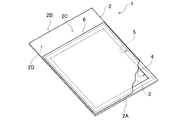
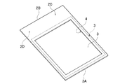
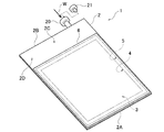
図1は、本発明の好ましい加湿用バッグの第1実施形態の外観を示す斜視図である。図2は、図1に示す加湿用バッグ1のバッグ本体2と、ガス透過性を有するガス透過フィルム3と、バッグ本体2の開口部4の形状例を示す斜視図である。
<First Embodiment>
FIG. 1 is a perspective view showing an appearance of a first preferred embodiment of a humidifying bag according to the present invention. FIG. 2 is a perspective view showing an example of the shape of the
図1と図2に示す加湿用バッグ1は、処理装置の内部、例えばCO2インキュベータの培養室内に、あるいはマルチインキュベータの培養室内に配置されることで、培養室内を加湿するための液体封入バッグである。
A humidifying
この加湿用バッグ1のバッグ本体2は、滅菌水のような液体を封入している。加湿用バッグ1は、その少なくとも一部分には、ガス透過性を有する材質のガス透過性フィルム3が配置されている。このガス透過性フィルム3は、バッグ本体2の開口部3を覆うようにして配置されている。
The
インキュベータでは、人間の細胞または動物の細胞等の培養物を培養するのに用いられる。インキュベータの培養室内では、培養物の培養のために90%以上の湿度環境が必要であることから、加湿用バッグ1が培養室内に配置される。これにより、加湿用バッグ1内の滅菌水の水蒸気は、ガス透過性を有する材質のガス透過性フィルム3を通じて、加湿用バッグ1のバッグ本体2内から培養室内を加湿できる。ただし、ガス透過性フィルム3は、液体である滅菌水を通さないので、液体の滅菌水自体が加湿用バッグ1内からガス透過性フィルム3を通じて漏れることは無い。
In an incubator, it is used for culturing cultures such as human cells or animal cells. Since a humidity environment of 90% or more is necessary for culturing the culture in the incubator culture chamber, the
次に、加湿用バッグ1の好ましい構造例を、さらに説明する。
Next, a preferable structural example of the humidifying
図1と図2に示す加湿用バッグ1は、バッグ本体2を有する。このバッグ本体2は、例えば、耐熱性を有するプラスチック製の袋状の部材である。バッグ本体2は、内部に入れる液体が漏れない、例えば透明な材質、ポリエチレンフィルムやビニールフィルム等により作られている。バッグ本体2は、透明なフィルムに限らず、半透明あるいは不透明なフィルムにより作ることもでき、特に材質には限定されない。
A humidifying
バッグ本体2を作成する素材は、例えば筒状に予め形成されていることにより、バッグ本体2の一端部2Aと他端部2Bは、それぞれ開口部を有している。バッグ本体2の一端部2Aは、ヒートシールにより封じることで、一端部2Aの開口部は予め閉じる。
The material for creating the
例えば、バッグ本体2の内部には、バッグ本体2の他端部2Bの開口部から滅菌水を充填して、その後にバッグ本体2の他端部2Bを、ヒートシールにより封じることで、バッグ本体2内には、滅菌水を封入する。これにより、このバッグ本体2の内部には、加湿用の水蒸気を発生させるための液体としての滅菌水が漏れないように封入されている。
For example, the
図1と図2に示すように、バッグ本体2は、例えば長方形の袋状の部材であるが、バッグ本体2は、第1面部2Cと、第1面部2Cとは反対側の第2面部2Dを有する。バッグ本体2の第1面部2Cには、例えば長方形状あるいは正方形状の開口部4が設けられている。この開口部4の面積は、第1面部2Cにおいて、要求される滅菌水の水蒸気量に応じて、任意に設定することができる。
As shown in FIGS. 1 and 2, the
図2に示すように、ガス透過性フィルム3はガス透過性部材の例である。ガス透過性フィルム3の4辺部は、バッグ本体2の第1面部2Cの内面側において、第1面部2Cの内面に対して、例えばヒートシールにより密着して固定されている。ガス透過性フィルム3は、開口部4の形状に合わせて、長方形状あるいは正方形状に形成されており、ガス透過性フィルム3の縦方向の寸法と横方向の寸法は、開口部4を確実に覆うことができるように、開口部4の縦方向の寸法と横方向の寸法に比べて、大きく設定されている。
As shown in FIG. 2, the gas
これにより、ガス透過性フィルム3は、開口部4を、第1面部2Cの内面側から密着して覆っている。このため、バッグ本体2内の滅菌水が、ガス透過性フィルム3とバッグ本体2の第1面部2Cの内面との間から、バッグ本体2の外部に漏れることは全くない。
Thus, the gas
このガス透過性フィルム3は、例えば滅菌水W(液体)の水蒸気(気体)は通すことができるガス透過性を有するが、液体は通さない性質を有する材質、例えば高密度ポリエチレン不織布を用いている。ガス透過性フィルム3は、気体は通すが液体は通さない微小な孔を有する有孔フィルム、とも呼ぶことができる。
The gas
次に、図3と図1を参照する。 Reference is now made to FIGS.
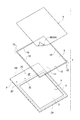
図3は、図1に示す加湿用バッグ1のバッグ本体2と、ガス透過フィルム3と、水蒸気透過防止シート5と、被覆シート6を示す分解斜視図である。
FIG. 3 is an exploded perspective view showing the
図3に示すように、加湿用バッグ1は、バッグ本体2とガス透過フィルム3に加えて、好ましくは水蒸気透過防止シート5と被覆シート6を有している。水蒸気透過防止シート5はガス透過防止シートの例である。
As shown in FIG. 3, the
水蒸気透過防止シート5は、バッグ本体2の開口部4の形状に合わせて、長方形状あるいは正方形状に形成されている。この水蒸気透過防止シート5の縦方向の寸法と横方向の寸法は、開口部4とガス透過フィルム3を確実に覆うことができるように、開口部4の縦方向の寸法と横方向の寸法に比べて、大きく設定されている。この水蒸気透過防止シート5は、水蒸気を通さない例えばプラスチック製の薄いフィルムである。被覆シート6は、水蒸気透過防止シート5を、例えば上から完全に覆うことができるような寸法を有する長方形状あるいは正方形状のシートである。
The water vapor
この被覆シート6の裏面6Aの全面には、粘着部6Bが形成されており、被覆シート6は、水蒸気透過防止シート5を完全に覆うようにして、水蒸気透過防止シート5の外面とバッグ本体2の第1面部2Cの外面に対して貼り付ける。これにより、被覆シート6は、水蒸気透過防止シート5とガス透過フィルム3を完全に覆うことができる。
An
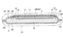
図4は、図1と図3に示す加湿用バッグ1の断面構造例を示す模式図である。図5は、図4に示す加湿用バッグ1を外装袋13で包装した状態を示す模式図である。
FIG. 4 is a schematic diagram showing an example of a cross-sectional structure of the
図4に示すように、ガス透過性フィルム3は、バッグ本体2の開口部4に対応するようにして、バッグ本体2の第1面部2Cの内面2E側に密着して固定されている。一方、水蒸気透過防止シート5は、バッグ本体2の開口部4を覆うようにして、バッグ本体2の第1面部2Cの外面2F側に密着して固定されている。
As shown in FIG. 4, the gas
ガス透過性フィルム3と水蒸気透過防止シート5を、バッグ本体2の第1面部2Cに対して固定する方法としては、好ましくは次のように行う。例えば、バッグ本体2の一端部2Aの開口部と他端部2Bの開口部を閉じる前に、バッグ本体2内にヒートシール用の加熱部材を入れるとともに、バッグ本体2の外側には、対応する別の加熱部材を対応して配置させる。この状態で、ガス透過性フィルム3の4辺部の接着剤と水蒸気透過防止シート5の4辺部の接着剤は、第1面部2Cの内面2Eと第1面部2Cの外面2Fに対してそれぞれ圧着することにより、同時に固定されている。
As a method for fixing the gas
これにより、ガス透過性フィルム3と水蒸気透過防止シート5は、一度のヒートシール作業で、ガス透過性フィルム3と水蒸気透過防止シート5が、バッグ本体2の第1面部2Cに対して、第1面部2Cの内面2Eと外面2F側において密着して固定できる。すなわち、一度のヒートシール作業により、ガス透過性フィルム3は、バッグ本体2の開口部4に対応するようにして、バッグ本体2の第1面部2Cの内面側に固定されるとともに、水蒸気透過防止シート5は、バッグ本体2の開口部4に対応するようにして、バッグ本体2の第1面部2Cの外面2F側に固定される。
As a result, the gas
図4と図5に示すように、好ましくは、水蒸気透過防止シート5は、その4辺部において、例えば連続した切り込み部分10が、予め形成されている。この切り込み部分10は、水蒸気透過防止シート5の外面側から、水蒸気透過防止シート5の肉厚の途中位置まで形成されているハーフカットの溝である。この切り込み部分10は、連続して形成されていても、断続的に形成されていても良い。
As shown in FIGS. 4 and 5, preferably, the water vapor
これにより、水蒸気透過防止シート5は、切り込み部分10を境にして、切り込み部分10の内側の領域である長方形状あるいは正方形状の剥離部分11と、切り込み部分10の外側の領域である枠型の残存部分12と、に区分されている。この切り込み部分10は、図3にも示している。
As a result, the water vapor
この剥離部分11の寸法は、バッグ本体2の開口部4の寸法と同じか、開口部4の寸法よりやや大きい。これは、培養室内を加湿する時に剥離部分11を剥離した場合に、開口部4の全部を露出させるためである。枠型の残存部分12は、バッグ本体2の第1面部2Cの外面2Fにおいて、開口部4の外側の位置に残す部分である。
The size of the peeling
図4と図5に示すように、バッグ本体2の一端部2Aの開口部と他端部2Bの開口部は、例えばヒートシールにより封止されており、バッグ本体2の内部には、液体としての滅菌水Wが充填されている。このように滅菌水Wが充填された状態では、バッグ本体2の開口部4は、ガス透過性フィルム3により完全に封鎖されているので、バッグ本体2内の滅菌水Wが開口部4から、バッグ本体2の外側に漏れ出ることを確実に防いでいる。
As shown in FIG. 4 and FIG. 5, the opening of the one
しかも、水蒸気透過防止シート5が、バッグ本体2の開口部4を外側から塞いでいるので、加湿用バッグ1の未使用時には、水蒸気透過防止シート5は、滅菌水Wの水蒸気が、ガス透過性フィルム3を通じて外部に放出されてしまうのを、確実に防ぐことができる。
図5に例示する最終的な製品の状態では、図4に示す加湿用バッグ1は、外装袋13により包装されている。従って、加湿用バッグ1は、未使用時には図5に示す外装袋13により保護され、しかも水蒸気がバッグ本体2から漏れ出ることはない。
Moreover, since the water vapor permeation
In the final product state illustrated in FIG. 5, the
加湿用バッグ1がインキュベータの培養室内を加湿する際には、図6に示すように、作業者は被覆シート6を剥離することで、水蒸気透過防止シート5の剥離部分11を剥離シート6と一緒に除去できるようになっている。
When the
次に、上述した加湿用バッグ1が配置されるインキュベータの好ましい例として、図7を参照して、CO2インキュベータ100を説明する。
Next, a
CO2インキュベータ100は、CO2インキュベータ100の培養室101の庫内温度とCO2濃度を制御して、高いCO2濃度を必要する培養細胞等を培養するのに用いられる。CO2インキュベータ100は、図示しないが動物細胞培養室に設置されており、動物細胞培養室は、その室内には殺菌灯を備える。動物細胞培養室の隣には、クリーンベンチが置かれ、無菌操作後、すぐに培養することができる環境にある。
The
CO2インキュベータ100を用いて培養細胞を行う場合には、例えばCO2の濃度は5%である。このように、培養細胞を行う場合に、所定のCO2濃度、例えば5%濃度のCO2を用いるのは、次の理由からである。
When cultured cells are used using the
(1)pHの維持
細胞を培養して時間が経つと、培養液中のpHは酸性側に傾き易い。そこで、培養液中に炭酸水素ナトリウムを混ぜて、インキュベータに薄い炭酸ガスを存在させると、緩衝作用が生じてpHが変動しにくくなる。なお、培養液が酸性になると、色の変化する物質を混ぜておき、色が変化したら培養液の交換をする必要がある。
(1) Maintenance of pH When cells are cultured and time passes, the pH in the culture solution tends to be inclined toward the acidic side. Therefore, when sodium hydrogen carbonate is mixed in the culture medium and a thin carbon dioxide gas is present in the incubator, a buffering action is generated and the pH is hardly changed. In addition, when a culture solution becomes acidic, it is necessary to mix a substance that changes color, and to change the culture solution when the color changes.
(2)二酸化炭素の要求性
光合成細菌の全部ではないが、代表的な光合成細菌には、二酸化炭素を炭素原として要求するものがある。
(2) Requirement for carbon dioxide Some, but not all, photosynthetic bacteria require carbon dioxide as a carbon source.
(3)動脈血の二酸化炭素分圧
二酸化炭素が大気中に5%存在すると、大気圧760mmHgの5%なので、二酸化炭素の分圧は、38mmHgになり、これは動脈血二酸化炭素分圧と等しい。
(3) Carbon dioxide partial pressure of arterial blood If carbon dioxide is present in the atmosphere at 5%, the atmospheric pressure is 5% of 760 mmHg, so the partial pressure of carbon dioxide is 38 mmHg, which is equal to the arterial blood carbon dioxide partial pressure.
次に、上述した加湿用バッグ1が適用されるCO2インキュベータの好ましい構造例を、図7を参照して説明する。
Next, a preferred structural example of a
図7は、上述した加湿用バッグ1が適用されるCO2インキュベータの好ましい実施形態を示す縦方向の断面図である。
FIG. 7 is a longitudinal sectional view showing a preferred embodiment of a
図7に示すCO2インキュベータ100は、内部に直方体状の培養室101を有する。この培養室101は、いわゆるウォータージャケット方式の加熱方式を採用することにより、培養室101の槽内の壁面温度を均一に制御可能である。また、培養室101では、上下気流による微風循環方式により、雑菌の温床となる槽内の壁面の結露を最小限に抑えることができる。
A
図7に示すように、CO2インキュベータ100は、本体部102と、扉103を有している。本体部102と扉103は、金属製の直方体の箱体を構成しており、その内部には培養室101が設けられている。本体部102は、前面開口部104を有する。扉103は、ヒンジにより本体部102に取り付けられており、扉103は、前面開口部104を開閉可能である。扉103内には、ヒータ105と断熱材(図示せず)が配置されている。扉103の前面には、タッチパネル式の操作部106が配置されている。
As shown in FIG. 7, the
本体部102は、ウォータージャケット107を備える。ウォータージャケット107は、培養室101の天面、底面、左右側面、背面に配置されている。また、ヒータHが、底面のウォータージャケット107(符号107Aで表示)に配置されている。これにより、培養室101は、いわゆるウォータージャケット方式の採用により、槽内の壁面温度を均一に制御可能である。
The
本体部102の背部には、シロッコファン108と、CO2供給口109が設けられている。シロッコファン108が、制御部の指令により動作することで、培養室101内の雰囲気では、矢印Rで示すように、上下気流による微風循環方式により、雑菌の温床となる槽内の壁面の結露を最小限に抑えることができる。CO2供給口109は、外部から培養室101内に、二酸化炭素を供給することで、培養室101内のCO2濃度を、例えば5%に設定する。
A
図7に示すように、底面のウォータージャケット107Aは、加湿用バッグ1を位置決めするための位置決め用凹部120を有している。位置決め用凹部120が形成されている深さは、例えば1mm〜2mm程度である。
As shown in FIG. 7, the
この位置決め用凹部120は、加湿用バッグ1を、培養室101の底部において、位置ずれしないように、位置決めして配置するために設けられている。
The
このヒータHが発生する熱は、位置決め用凹部120において位置決めされた加湿用バッグ1を加熱することで、加湿用バッグ1から滅菌水の水蒸気Vを、ガス透過性フィルム3を通過させて、培養室101内に放出すのを促進させる。
The heat generated by the heater H heats the
次に、作業者が、上述した加湿用バッグ1を、図7に示すCO2インキュベータ100の培養室101内に配置して、滅菌水Wの水蒸気Vを用いて、培養室101内を加湿する例について説明する。
Next, an example in which the operator places the above-described
図6は、バッグ本体2から被覆シート6を剥して、水蒸気透過防止シート5の剥離部分11を被覆シート6とともに取り除くことで、バッグ本体2のガス透過性フィルム3を露出させた状態を示す模式図である。
FIG. 6 is a schematic view showing a state in which the gas
図5に示すように、使用前の加湿用バッグ1では、バッグ本体2の一端部2Aの開口部と他端部2Bの開口部は、すでに例えばヒートシールにより封止されており、バッグ本体2の内部には、滅菌水Wが予め充填されている。バッグ本体2の開口部4は、ガス透過性フィルム3による封鎖されているので、バッグ本体2内の滅菌水Wが、開口部4から漏れ出ることを確実に防いでいる。
As shown in FIG. 5, in the
しかも、使用前の加湿用バッグ1では、水蒸気透過防止シート5が、バッグ本体2の開口部4に露出したガス透過性フィルム3を外側から塞いでいるので、滅菌水Wの水蒸気が、ガス透過性フィルム3を通じて外部に放出されてしまうのを防いでいる。バッグ本体2内は、滅菌水Wにより完全滅菌されている。加湿用バッグ1は、外装袋13で包装されている。
Moreover, in the
そこで、作業者は、加湿用バッグ1を、図7に示すCO2インキュベータ100の培養室101内に配置する際には、この外装袋13を破って加湿用バッグ1を取り出す。
Therefore, when placing the
その後、図6に示すように、作業者は、被覆シート6を指で持って持ち上げてバッグ本体2の第1面部2Cの外面2Fから剥がして、加湿用バッグ1を、図7に示すCO2インキュベータ100の培養室101内の位置決め用凹部120内に、位置決めして置く。
Thereafter, as shown in FIG. 6, the operator lifts the
このように、図6に示す被覆シート6を、バッグ本体2の第1面部2Cの外面2F側から剥がすことで、被覆シート6の粘着部6Bは、水蒸気透過防止シート5の剥離部分11だけを、一緒に持ち上げることで、切り込み部分10から切り離して、ガス透過性フィルム3から取り除くことができる。このように、剥離部分11は、バッグ本体2の開口部4の上から取り除くことができことから、バッグ本体2の開口部4を覆っているガス透過性フィルム3を露出させることができる。
6 is peeled off from the
図6に示すように、バッグ本体2の開口部4を覆っているガス透過性フィルム3が露出されると、バッグ本体2内の滅菌水Wは、図6と図7に示すヒータHの発熱により滅菌水Wの水蒸気化が促進されて水蒸気Vとなる。この水蒸気Vが、ガス透過性フィルム3を通過して、図7に示す培養室101内に供給される。
As shown in FIG. 6, when the gas
そして、水蒸気Vは、図7に示すように、培養室101内の雰囲気では、矢印Rで示すように、上下気流による微風循環方式により循環されることで、人間の細胞または動物の細胞等の培養物を培養するために、培養室101内は90%以上の湿度環境に保持される。
Then, as shown in FIG. 7, the water vapor V is circulated in the atmosphere in the
ところで、加湿用バッグ1を、図7に示すCO2インキュベータ100の培養室101内の位置決め用凹部120内に置くことができるので、作業者は、培養室101内で加湿用バッグ1を容易に位置決めできる。しかも、位置決め用凹部120が、培養室101の底部に設けられていることから、作業者は、加湿用バッグ1を培養室101内のどこに置くべきかを判別し易いメリットがある。
By the way, the
上述した構成の加湿用バッグ1を用いることで、従来の加湿バットを用いる場合に比べて、インキュベータ100の培養室101内で水のような液体Wが零れることが全く無くなる。このことから、培養室101内の湿度環境を得ようとする場合に、取扱いが容易になり、培養室101内を容易に加湿することができる。このため、インキュベータ100による細胞培養作業の作業性を上げることができる。
By using the
また、例えば地震等の外力がCO2インキュベータ100に加わっても、加湿用バッグ1を用いることで、水が零れてしまうといった不都合は無くなる。
In addition, even when an external force such as an earthquake is applied to the
<第2実施形態>
次に、図8は、本発明の加湿用バッグの第2実施形態を示す斜視図である。
Second Embodiment
Next, FIG. 8 is a perspective view showing a second embodiment of the humidifying bag of the present invention.
図8に示す加湿用バッグ1は、図1と図5に示す第1実施形態の加湿用バッグ1とほぼ同じ構造を有しているが、次の点が異なる。
The
図1と図5に示す第1実施形態の滅菌水Wが既に封入されている加湿用バッグ1では、図5に示すように、バッグ本体2の内部は滅菌水Wが予め充填されている。この加湿バッグ1は、予め滅菌水Wを充填した製品となっていることから、作業者は、加湿用バッグ1を培養室101内に配置すれば、培養室101内の加湿処理は直ぐに行える。
In the
これに対して、図8に示す第2実施形態の加湿用バッグ1の場合には、バッグ本体2の一端部2Aと他端部2Bは、共に封止されており、しかもバッグ本体2の他端部2Bに、滅菌水を注入して充填するための注入部20を備えている。この加湿用バッグ1は、バッグ本体2内には予め滅菌水は充填されておらず、空状態である。
On the other hand, in the case of the
これにより、図8に示す第2実施形態の加湿用バッグ1の場合には、作業者は、加湿用バッグ1のバッグ本体2内に、後から注入部20を通じて、必要とする液体、例えば滅菌水Wを充填することができる。この後、注入部20は栓21により閉じれば、加湿用バッグ1は滅菌水Wを漏れないように封入できる。
Thereby, in the case of the
<第3実施形態>
次に、図9は、本発明の加湿用バッグの第3実施形態を示す正面図である。
<Third Embodiment>
Next, FIG. 9 is a front view showing a third embodiment of the humidifying bag of the present invention.
図9に示す第3実施形態の加湿用バッグ1Sが、図1と図5に示す第1実施形態の加湿用バッグ1は、ほぼ同じ構造を有しているが、次の点が異なる。
Although the humidifying bag 1S of the third embodiment shown in FIG. 9 has substantially the same structure as the
この加湿用バッグ1Sは、上端部に延長部1Tを有している。この延長部1Tには、孔1Hが形成されている。培養室内には支持棒Pが配置されている。延長部1Tは、フック1Rを用いてこの支持棒Pに対して着脱可能に吊り下げることができる。このようにすることで、加湿用バッグ1Sは、培養室内に吊り下げるようにして、培養室の中間位置から加湿することができる。もちろん、加湿用バッグ1Sは、吊り下げないで、培養室の底部に置いてよい。 The humidifying bag 1S has an extension 1T at the upper end. The extension 1T is formed with a hole 1H. A support rod P is disposed in the culture chamber. The extension 1T can be detachably suspended from the support bar P using the hook 1R. In this way, the humidifying bag 1S can be humidified from the middle position of the culture chamber so as to be suspended in the culture chamber. Of course, the humidifying bag 1S may be placed at the bottom of the culture chamber without being suspended.
上述したように、本発明の実施形態の加湿用バッグ1(1S)は、インキュベータ100のような処理装置の内部を加湿するための加湿用バッグである。
As described above, the humidifying bag 1 (1S) according to the embodiment of the present invention is a humidifying bag for humidifying the inside of a processing apparatus such as the
加湿用バッグ1(1S)は、開口部4を有し、液体(例えば滅菌水W)を封入するためのバッグ本体2と、バック本体2の開口部4を閉じるようにバッグ本体2に配置されて、バッグ本体2内の液体は通さずに液体のガス(滅菌水Wの水蒸気)を通して、装置の内部の例であるインキュベータ100の培養室101を加湿するガス透過性部材3と、ガス透過性部材3を覆うことで、ガス透過性部材3からガスがバッグ本体2の外に出るのを防ぎ、インキュベータ100の培養室101を加湿する際には外して、ガス透過性部材3を露出させるガス透過防止シート5を備える。
The humidifying bag 1 (1S) has an
これにより、加湿用バッグ1(1S)では、バッグ本体2が液体を封入した状態で、ガス透過性部材3は液体を通さずに、ガス透過防止シート5は、ガス透過性部材3から液体のガスがインキュベータ100の培養室101内に漏れるのを防ぐことができる。
Thus, in the humidifying bag 1 (1S), the gas
このため、加湿用バッグ1は、インキュベータ100の培養室101内で水のような液体が零れることが全く無くなるので、従来の加湿バットを用いるのに比べて、取り扱いが容易である。しかも、ガス透過防止シート5を取り除けば、ガス透過性部材3から液体のガスが漏れるので、その液体のガスにより培養室101内を容易に加湿することができる。
For this reason, the
加湿用バッグ1(1S)では、ガス透過防止シート5上に粘着により配置され、インキュベータ100の培養室101内を加湿する際には、剥がすことで、ガス透過防止シート5をガス透過性部材3から取り除くための被覆シート6を有している。
In the humidifying bag 1 (1S), the gas permeation
これにより、被覆シート6を剥がすことで、被覆シートと6ともにガス透過防止シート5を、容易にしかも確実にガス透過性部材3から取り除くことができる。
Thereby, by peeling off the
加湿用バッグ1では、ガス透過防止シート5は、切り込み部分10を有し、切り込み部分10は、被覆シート6を剥がす際にガス透過性部材3から取り除かれる剥離部分11と、バッグ本体2側に残る残存部分12と、を分けている。これにより、インキュベータ100の培養室101内を加湿する際には被覆シート6を剥がすことで、被覆シート6とともにガス透過防止シート5の剥離部分11だけをガス透過性部材3から、容易にしかも確実に取り除くことができる。
In the
請求項4に記載の加湿用バッグでは、バッグ本体は、液体を入れるための注入部を有する。これにより、作業者は、インキュベータ100の培養室101内を加湿する際には、加湿用バッグ1内に、後から、加湿に必要する任意の液体を注入することができる。
In the humidifying bag according to
請求項5に記載の加湿用バッグを備えたインキュベータは、内部を所定の湿度環境にするインキュベータであって、開口部を有し、液体を封入するためのバッグ本体と、バック本体の開口部を閉じるようにバッグ本体に配置されて、バッグ本体内の液体は通さずに液体のガスを通してインキュベータの内部を加湿するガス透過性部材と、ガス透過性部材を覆うことで、ガス透過性部材からガスがバッグ本体の外に出るのを防ぎ、インキュベータの内部を加湿する際には外して、ガス透過性部材を露出させるガス透過防止シートと、を有する加湿用バッグを、備える。
An incubator provided with the humidifying bag according to
これにより、加湿用バッグ1(1S)を備えたインキュベータ100では、加湿用バッグ1(1S)のバッグ本体2が液体を封入した状態で、ガス透過性部材3は液体を通さずに、ガス透過防止シート5は、ガス透過性部材3から液体のガスがインキュベータ100の培養室101内に漏れるのを防ぐことができる。
Thereby, in the
このため、加湿用バッグ1は、インキュベータ100の培養室101内で水のような液体が零れることが全く無くなるので、従来の加湿バットを用いるのに比べて、取り扱いが容易である。しかも、ガス透過防止シート5を取り除けば、ガス透過性部材3から液体のガスが漏れるので、その液体のガスにより培養室101内を容易に加湿することができる。
For this reason, the
以上、実施形態を挙げて本発明を説明したが、各実施形態は一例であり、特許請求の範囲に記載される発明の範囲は、発明の要旨を逸脱しない範囲内で種々変更できるものである。 The present invention has been described with reference to the embodiments. However, each embodiment is an example, and the scope of the invention described in the claims can be variously modified without departing from the scope of the invention. .
本発明の実施形態の加湿用バッグが用いられるインキュベータとしては、CO2インキュベータを用いているが、これに限らずにマルチガスインキュベータであっても良い。
As the incubator in which the humidifying bag according to the embodiment of the present invention is used, a
図示したインキュベータ100では、加熱方式としては、底面に配置されたヒータと、側面と天面と背面に配置されたウォータージャケットを用いて、培養室内を加熱するウォータージャケット方式を採用している。
In the
しかしこれに限らず、インキュベータにおける別の加熱方式としては、底面に配置されたヒータと、側面と天面と背面に配置されたパネルヒータを用いて、培養室内を加熱するダイレクトヒートジャケット方式を採用しても良い。 However, not limited to this, another heating method in the incubator employs a direct heat jacket method that heats the culture chamber using a heater placed on the bottom and panel heaters placed on the side, top, and back. You may do it.
図7に示すように、底面のウォータージャケット107Aでは、位置決め用凹部120が、加湿用バッグ1を、培養室101の底部において、位置ずれしないように配置するために設けられている。しかしこれに限らず、底面のウォータージャケット107Aは、位置決め用凹部120を設けずに、平坦であっても良い。
As shown in FIG. 7, in the
上述した図4から図6に示すように、加湿用バッグ1(1S)では、バッグ本体2の第1面部2C側だけに開口部4が形成され、その開口部4はガス透過性フィルム3により覆うようにして閉鎖されている。しかし、本発明の実施形態の加湿用バッグ1(1S)では、バッグ本体2の第1面部2Cと第2面部2Dの両方に開口部が形成され、これらの開口部はそれぞれガス透過性フィルム3により覆うようにして閉鎖する構造を採用しても良い。
As shown in FIGS. 4 to 6 described above, in the humidifying bag 1 (1S), the
インキュベータの種類や培養室の大小や、インキュベータによる培養実験内容に応じて、開口部4は、バッグ本体2の第1面部2Cと第2面部2Dの少なくとも一方に設け、その開口部4の面積を設定すれば良い。インキュベータの種類や培養室の大小や、インキュベータによる培養実験内容に応じて、小さいサイズのバッグ本体2に対して大きな開口部4を設けたり、大きいサイズのバッグ本体2に対して小さい開口部4を設けることもできる。
The
加湿用バッグ1(1S)の形状は、図示した長方形状や正方形状のものに限らず、円形形状などの他の形状であっても良く、特に限定されない。 The shape of the humidifying bag 1 (1S) is not limited to the illustrated rectangular shape or square shape, and may be other shapes such as a circular shape, and is not particularly limited.
加湿用バッグ1(1S)に形成されている開口部4の形状は、図示した長方形状や正方形状に限らず、円形形状などの他の形状であっても良く、特に限定されない。
The shape of the
加湿用バッグ1(1S)に封入される液体としては、培養室101内を90%以上の湿度環境にするために滅菌水Wを用いているが、これに限らず、他の種類の水や、水とは異なる種類の液体であっても良い。 As the liquid sealed in the humidifying bag 1 (1S), the sterilized water W is used in order to make the inside of the culture chamber 101 a humidity environment of 90% or more. However, the present invention is not limited to this. The liquid may be a different type from water.
また、加湿用バッグ1は、培養室101において、従来用いられている上蓋の無いトレイ式のバット内に配置しても良い。
Further, the
1 加湿用バッグ
1S 加湿用バッグ
2 バッグ本体
3 ガス透過性フィルム(ガス透過性部材)
4 開口部
5 水蒸気透過防止シート(ガス透過防止シート)
6 被覆シート
11 水蒸気透過防止シートの剥離部分
12 水蒸気透過防止シートの残存部分
100 インキュベータ
101 培養室
H ヒータ
DESCRIPTION OF
4
6
Claims (5)
開口部を有し、液体を封入するためのバッグ本体と、
前記バック本体の前記開口部を閉じるように前記バッグ本体に配置されて、前記バッグ本体内の前記液体は通さずに前記液体のガスを通して前記装置の内部を加湿するガス透過性部材と、
前記ガス透過性部材を覆うことで、前記ガス透過性部材から前記ガスが前記バッグ本体の外に出るのを防ぎ、前記装置の内部を加湿する際には外して、前記ガス透過性部材を露出させるガス透過防止シートと、を備えることを特徴とする加湿用バッグ。 A humidifying bag for humidifying the inside of the device,
A bag body having an opening and enclosing a liquid;
A gas permeable member disposed in the bag body so as to close the opening of the back body, and humidifying the inside of the device through the liquid gas without passing the liquid in the bag body;
Covering the gas permeable member prevents the gas from coming out of the bag body from the gas permeable member, and removes the gas permeable member when the interior of the device is humidified. A humidifying bag comprising: a gas permeation preventing sheet.
開口部を有し、液体を封入するためのバッグ本体と、
前記バック本体の前記開口部を閉じるように前記バッグ本体に配置されて、前記バッグ本体内の前記液体は通さずに前記液体のガスを通して前記インキュベータの内部を加湿するガス透過性部材と、
前記ガス透過性部材を覆うことで、前記ガス透過性部材から前記ガスが前記バッグ本体の外に出るのを防ぎ、前記インキュベータの内部を加湿する際には外して、前記ガス透過性部材を露出させるガス透過防止シートと、を有する加湿用バッグを、
備えることを特徴とする加湿用バッグを備えたインキュベータ。 An incubator that keeps the interior at a predetermined humidity environment
A bag body having an opening and enclosing a liquid;
A gas permeable member disposed in the bag body so as to close the opening of the back body, and humidifying the interior of the incubator through the liquid gas without passing the liquid in the bag body;
Covering the gas permeable member prevents the gas from coming out of the bag body from the gas permeable member, and removes the gas permeable member when humidifying the inside of the incubator. A humidifying bag having a gas permeation preventing sheet,
An incubator provided with a humidifying bag.
Priority Applications (1)
| Application Number | Priority Date | Filing Date | Title |
|---|---|---|---|
| JP2016003263A JP6668080B2 (en) | 2016-01-12 | 2016-01-12 | Humidifying bag and incubator with humidifying bag |
Applications Claiming Priority (1)
| Application Number | Priority Date | Filing Date | Title |
|---|---|---|---|
| JP2016003263A JP6668080B2 (en) | 2016-01-12 | 2016-01-12 | Humidifying bag and incubator with humidifying bag |
Publications (2)
| Publication Number | Publication Date |
|---|---|
| JP2017123786A true JP2017123786A (en) | 2017-07-20 |
| JP6668080B2 JP6668080B2 (en) | 2020-03-18 |
Family
ID=59363324
Family Applications (1)
| Application Number | Title | Priority Date | Filing Date |
|---|---|---|---|
| JP2016003263A Active JP6668080B2 (en) | 2016-01-12 | 2016-01-12 | Humidifying bag and incubator with humidifying bag |
Country Status (1)
| Country | Link |
|---|---|
| JP (1) | JP6668080B2 (en) |
Cited By (4)
| Publication number | Priority date | Publication date | Assignee | Title |
|---|---|---|---|---|
| JP2019005239A (en) * | 2017-06-25 | 2019-01-17 | 株式会社大一商会 | Game machine |
| JP2019005240A (en) * | 2017-06-25 | 2019-01-17 | 株式会社大一商会 | Game machine |
| EP3778853A1 (en) | 2019-08-12 | 2021-02-17 | Adolf Kühner AG | Water bath for humidifying an interior of an incubator |
| CN115418318A (en) * | 2022-09-02 | 2022-12-02 | 广州市华粤行医疗科技有限公司 | Temperature-adjustable condensation-preventing culture device and flow control method for wet culture |
Citations (6)
| Publication number | Priority date | Publication date | Assignee | Title |
|---|---|---|---|---|
| JPH03124578A (en) * | 1989-09-28 | 1991-05-28 | Terumo Corp | Cell preservation container |
| JPH10337178A (en) * | 1997-03-19 | 1998-12-22 | Becton Dickinson & Co | Culture container assembly, lid used for the same, and cell culture method using the same |
| WO2003104387A1 (en) * | 2002-06-06 | 2003-12-18 | 和研薬株式会社 | Tissue culture apparatus |
| JP2005295825A (en) * | 2004-04-07 | 2005-10-27 | Wakenyaku Kk | Bag-shaped humidity supply vessel |
| JP3129610U (en) * | 2006-12-07 | 2007-03-01 | 和研薬株式会社 | Bag-like humidity supply container |
| JP2016101095A (en) * | 2014-11-27 | 2016-06-02 | 大日本印刷株式会社 | Cell culture vessel, cell culture vessel filled with culture medium, and culture method of cell |
-
2016
- 2016-01-12 JP JP2016003263A patent/JP6668080B2/en active Active
Patent Citations (7)
| Publication number | Priority date | Publication date | Assignee | Title |
|---|---|---|---|---|
| JPH03124578A (en) * | 1989-09-28 | 1991-05-28 | Terumo Corp | Cell preservation container |
| JPH10337178A (en) * | 1997-03-19 | 1998-12-22 | Becton Dickinson & Co | Culture container assembly, lid used for the same, and cell culture method using the same |
| US5863792A (en) * | 1997-03-19 | 1999-01-26 | Becton Dickson And Company | Culture vessel assembly |
| WO2003104387A1 (en) * | 2002-06-06 | 2003-12-18 | 和研薬株式会社 | Tissue culture apparatus |
| JP2005295825A (en) * | 2004-04-07 | 2005-10-27 | Wakenyaku Kk | Bag-shaped humidity supply vessel |
| JP3129610U (en) * | 2006-12-07 | 2007-03-01 | 和研薬株式会社 | Bag-like humidity supply container |
| JP2016101095A (en) * | 2014-11-27 | 2016-06-02 | 大日本印刷株式会社 | Cell culture vessel, cell culture vessel filled with culture medium, and culture method of cell |
Cited By (6)
| Publication number | Priority date | Publication date | Assignee | Title |
|---|---|---|---|---|
| JP2019005239A (en) * | 2017-06-25 | 2019-01-17 | 株式会社大一商会 | Game machine |
| JP2019005240A (en) * | 2017-06-25 | 2019-01-17 | 株式会社大一商会 | Game machine |
| EP3778853A1 (en) | 2019-08-12 | 2021-02-17 | Adolf Kühner AG | Water bath for humidifying an interior of an incubator |
| US11365384B2 (en) | 2019-08-12 | 2022-06-21 | Adolf Kühner Ag | Water bath for humidifying an interior of an incubator |
| CN115418318A (en) * | 2022-09-02 | 2022-12-02 | 广州市华粤行医疗科技有限公司 | Temperature-adjustable condensation-preventing culture device and flow control method for wet culture |
| CN115418318B (en) * | 2022-09-02 | 2024-04-19 | 广州市华粤行医疗科技有限公司 | Temperature-adjustable condensation-prevention culture device and flow control method for wet culture |
Also Published As
| Publication number | Publication date |
|---|---|
| JP6668080B2 (en) | 2020-03-18 |
Similar Documents
| Publication | Publication Date | Title |
|---|---|---|
| CN1329501C (en) | Culture dish and bioreactor system | |
| JP6668080B2 (en) | Humidifying bag and incubator with humidifying bag | |
| EP2573163A1 (en) | Culture apparatus having heaters | |
| US5736355A (en) | Self contained biological indicator | |
| CN101410504B (en) | Culture apparatus | |
| JP5662927B2 (en) | Packaging container | |
| US5160700A (en) | Sterilizing system and method | |
| JPH11226095A (en) | Container monitoring system | |
| KR101920126B1 (en) | Cell culture container and container in which cell culture has been accommodated | |
| JP2005095097A (en) | Incubator | |
| EP3260529B1 (en) | Incubator | |
| JP2013128458A (en) | Packaging container | |
| JPWO2016159226A1 (en) | Incubator and incubator system with clean bench function | |
| US3283743A (en) | Environmental control chamber | |
| CN104293657A (en) | Sealed culture dish | |
| CN204237788U (en) | A kind of closed culture dish | |
| KR101824143B1 (en) | Ethylene oxide gas sterilizer | |
| CN103773683B (en) | Layer-stepping Tissue Culture Plate | |
| ES2843694T3 (en) | Incubator | |
| JP2009524417A (en) | Cell culture apparatus and method | |
| TWM338547U (en) | Apparatus for cultivating mushroom | |
| JP4761213B2 (en) | Microorganism culture equipment | |
| JP2005087029A (en) | Culture apparatus and culture kit | |
| US5143617A (en) | In-line moisture filter usable in an improved packaging system for a sterilizable calibratable medical device | |
| JP2005295825A (en) | Bag-shaped humidity supply vessel |
Legal Events
| Date | Code | Title | Description |
|---|---|---|---|
| A621 | Written request for application examination |
Free format text: JAPANESE INTERMEDIATE CODE: A621 Effective date: 20181211 |
|
| A977 | Report on retrieval |
Free format text: JAPANESE INTERMEDIATE CODE: A971007 Effective date: 20190918 |
|
| A131 | Notification of reasons for refusal |
Free format text: JAPANESE INTERMEDIATE CODE: A131 Effective date: 20190924 |
|
| A521 | Request for written amendment filed |
Free format text: JAPANESE INTERMEDIATE CODE: A523 Effective date: 20191106 |
|
| TRDD | Decision of grant or rejection written | ||
| A01 | Written decision to grant a patent or to grant a registration (utility model) |
Free format text: JAPANESE INTERMEDIATE CODE: A01 Effective date: 20200204 |
|
| A61 | First payment of annual fees (during grant procedure) |
Free format text: JAPANESE INTERMEDIATE CODE: A61 Effective date: 20200226 |
|
| R150 | Certificate of patent or registration of utility model |
Ref document number: 6668080 Country of ref document: JP Free format text: JAPANESE INTERMEDIATE CODE: R150 |
|
| R250 | Receipt of annual fees |
Free format text: JAPANESE INTERMEDIATE CODE: R250 |
|
| R250 | Receipt of annual fees |
Free format text: JAPANESE INTERMEDIATE CODE: R250 |
|
| R250 | Receipt of annual fees |
Free format text: JAPANESE INTERMEDIATE CODE: R250 |
|
| R250 | Receipt of annual fees |
Free format text: JAPANESE INTERMEDIATE CODE: R250 |